JP7158397B2 - Hybrid induction motor with self-regulating hybrid induction/permanent magnet rotor - Google Patents
Hybrid induction motor with self-regulating hybrid induction/permanent magnet rotor Download PDFInfo
- Publication number
- JP7158397B2 JP7158397B2 JP2019544851A JP2019544851A JP7158397B2 JP 7158397 B2 JP7158397 B2 JP 7158397B2 JP 2019544851 A JP2019544851 A JP 2019544851A JP 2019544851 A JP2019544851 A JP 2019544851A JP 7158397 B2 JP7158397 B2 JP 7158397B2
- Authority
- JP
- Japan
- Prior art keywords
- squirrel cage
- rotor
- motor
- bars
- cage bars
- Prior art date
- Legal status (The legal status is an assumption and is not a legal conclusion. Google has not performed a legal analysis and makes no representation as to the accuracy of the status listed.)
- Active
Links
- 230000006698 induction Effects 0.000 title description 33
- 241000555745 Sciuridae Species 0.000 claims description 78
- 230000001360 synchronised effect Effects 0.000 claims description 31
- 230000004907 flux Effects 0.000 claims description 22
- 230000004888 barrier function Effects 0.000 claims description 15
- 230000001939 inductive effect Effects 0.000 claims description 15
- 230000008878 coupling Effects 0.000 claims description 8
- 238000010168 coupling process Methods 0.000 claims description 8
- 238000005859 coupling reaction Methods 0.000 claims description 8
- 239000000463 material Substances 0.000 description 11
- RYGMFSIKBFXOCR-UHFFFAOYSA-N Copper Chemical compound [Cu] RYGMFSIKBFXOCR-UHFFFAOYSA-N 0.000 description 10
- 229910052802 copper Inorganic materials 0.000 description 10
- 239000010949 copper Substances 0.000 description 10
- 238000000034 method Methods 0.000 description 7
- 239000004020 conductor Substances 0.000 description 5
- 238000004804 winding Methods 0.000 description 5
- CWYNVVGOOAEACU-UHFFFAOYSA-N Fe2+ Chemical compound [Fe+2] CWYNVVGOOAEACU-UHFFFAOYSA-N 0.000 description 4
- 230000000694 effects Effects 0.000 description 4
- XAGFODPZIPBFFR-UHFFFAOYSA-N aluminium Chemical compound [Al] XAGFODPZIPBFFR-UHFFFAOYSA-N 0.000 description 3
- 229910052782 aluminium Inorganic materials 0.000 description 3
- XEEYBQQBJWHFJM-UHFFFAOYSA-N Iron Chemical compound [Fe] XEEYBQQBJWHFJM-UHFFFAOYSA-N 0.000 description 2
- 229910000831 Steel Inorganic materials 0.000 description 2
- 230000001133 acceleration Effects 0.000 description 2
- 239000010941 cobalt Substances 0.000 description 2
- 229910017052 cobalt Inorganic materials 0.000 description 2
- GUTLYIVDDKVIGB-UHFFFAOYSA-N cobalt atom Chemical compound [Co] GUTLYIVDDKVIGB-UHFFFAOYSA-N 0.000 description 2
- 239000002131 composite material Substances 0.000 description 2
- 238000003475 lamination Methods 0.000 description 2
- 239000003562 lightweight material Substances 0.000 description 2
- 229910052709 silver Inorganic materials 0.000 description 2
- 239000004332 silver Substances 0.000 description 2
- 229910001220 stainless steel Inorganic materials 0.000 description 2
- 239000010959 steel Substances 0.000 description 2
- 239000011800 void material Substances 0.000 description 2
- 229910000906 Bronze Inorganic materials 0.000 description 1
- 241000699800 Cricetinae Species 0.000 description 1
- 229920000271 Kevlar® Polymers 0.000 description 1
- 229910000596 Oilite Inorganic materials 0.000 description 1
- 230000004913 activation Effects 0.000 description 1
- 238000013459 approach Methods 0.000 description 1
- 239000010974 bronze Substances 0.000 description 1
- 230000008859 change Effects 0.000 description 1
- KUNSUQLRTQLHQQ-UHFFFAOYSA-N copper tin Chemical compound [Cu].[Sn] KUNSUQLRTQLHQQ-UHFFFAOYSA-N 0.000 description 1
- 230000005674 electromagnetic induction Effects 0.000 description 1
- 229910052742 iron Inorganic materials 0.000 description 1
- 238000012986 modification Methods 0.000 description 1
- 230000004048 modification Effects 0.000 description 1
- 229910001172 neodymium magnet Inorganic materials 0.000 description 1
- 229910052761 rare earth metal Inorganic materials 0.000 description 1
- 150000002910 rare earth metals Chemical class 0.000 description 1
- 238000009987 spinning Methods 0.000 description 1
Images


Classifications
-
- H—ELECTRICITY
- H02—GENERATION; CONVERSION OR DISTRIBUTION OF ELECTRIC POWER
- H02K—DYNAMO-ELECTRIC MACHINES
- H02K17/00—Asynchronous induction motors; Asynchronous induction generators
- H02K17/02—Asynchronous induction motors
- H02K17/26—Asynchronous induction motors having rotors or stators designed to permit synchronous operation
-
- H—ELECTRICITY
- H02—GENERATION; CONVERSION OR DISTRIBUTION OF ELECTRIC POWER
- H02K—DYNAMO-ELECTRIC MACHINES
- H02K1/00—Details of the magnetic circuit
- H02K1/06—Details of the magnetic circuit characterised by the shape, form or construction
- H02K1/12—Stationary parts of the magnetic circuit
- H02K1/14—Stator cores with salient poles
- H02K1/146—Stator cores with salient poles consisting of a generally annular yoke with salient poles
-
- H—ELECTRICITY
- H02—GENERATION; CONVERSION OR DISTRIBUTION OF ELECTRIC POWER
- H02K—DYNAMO-ELECTRIC MACHINES
- H02K1/00—Details of the magnetic circuit
- H02K1/06—Details of the magnetic circuit characterised by the shape, form or construction
- H02K1/22—Rotating parts of the magnetic circuit
- H02K1/223—Rotor cores with windings and permanent magnets
-
- H—ELECTRICITY
- H02—GENERATION; CONVERSION OR DISTRIBUTION OF ELECTRIC POWER
- H02K—DYNAMO-ELECTRIC MACHINES
- H02K1/00—Details of the magnetic circuit
- H02K1/06—Details of the magnetic circuit characterised by the shape, form or construction
- H02K1/22—Rotating parts of the magnetic circuit
- H02K1/24—Rotor cores with salient poles ; Variable reluctance rotors
- H02K1/246—Variable reluctance rotors
-
- H—ELECTRICITY
- H02—GENERATION; CONVERSION OR DISTRIBUTION OF ELECTRIC POWER
- H02K—DYNAMO-ELECTRIC MACHINES
- H02K16/00—Machines with more than one rotor or stator
- H02K16/02—Machines with one stator and two or more rotors
-
- H—ELECTRICITY
- H02—GENERATION; CONVERSION OR DISTRIBUTION OF ELECTRIC POWER
- H02K—DYNAMO-ELECTRIC MACHINES
- H02K17/00—Asynchronous induction motors; Asynchronous induction generators
- H02K17/02—Asynchronous induction motors
- H02K17/16—Asynchronous induction motors having rotors with internally short-circuited windings, e.g. cage rotors
- H02K17/165—Asynchronous induction motors having rotors with internally short-circuited windings, e.g. cage rotors characterised by the squirrel-cage or other short-circuited windings
-
- H—ELECTRICITY
- H02—GENERATION; CONVERSION OR DISTRIBUTION OF ELECTRIC POWER
- H02K—DYNAMO-ELECTRIC MACHINES
- H02K17/00—Asynchronous induction motors; Asynchronous induction generators
- H02K17/02—Asynchronous induction motors
- H02K17/16—Asynchronous induction motors having rotors with internally short-circuited windings, e.g. cage rotors
- H02K17/20—Asynchronous induction motors having rotors with internally short-circuited windings, e.g. cage rotors having deep-bar rotors
-
- H—ELECTRICITY
- H02—GENERATION; CONVERSION OR DISTRIBUTION OF ELECTRIC POWER
- H02K—DYNAMO-ELECTRIC MACHINES
- H02K19/00—Synchronous motors or generators
- H02K19/02—Synchronous motors
- H02K19/10—Synchronous motors for multi-phase current
- H02K19/103—Motors having windings on the stator and a variable reluctance soft-iron rotor without windings
-
- H—ELECTRICITY
- H02—GENERATION; CONVERSION OR DISTRIBUTION OF ELECTRIC POWER
- H02K—DYNAMO-ELECTRIC MACHINES
- H02K19/00—Synchronous motors or generators
- H02K19/02—Synchronous motors
- H02K19/14—Synchronous motors having additional short-circuited windings for starting as asynchronous motors
-
- H—ELECTRICITY
- H02—GENERATION; CONVERSION OR DISTRIBUTION OF ELECTRIC POWER
- H02K—DYNAMO-ELECTRIC MACHINES
- H02K21/00—Synchronous motors having permanent magnets; Synchronous generators having permanent magnets
- H02K21/46—Motors having additional short-circuited winding for starting as an asynchronous motor
-
- H—ELECTRICITY
- H02—GENERATION; CONVERSION OR DISTRIBUTION OF ELECTRIC POWER
- H02K—DYNAMO-ELECTRIC MACHINES
- H02K5/00—Casings; Enclosures; Supports
- H02K5/04—Casings or enclosures characterised by the shape, form or construction thereof
- H02K5/16—Means for supporting bearings, e.g. insulating supports or means for fitting bearings in the bearing-shields
- H02K5/173—Means for supporting bearings, e.g. insulating supports or means for fitting bearings in the bearing-shields using bearings with rolling contact, e.g. ball bearings
- H02K5/1732—Means for supporting bearings, e.g. insulating supports or means for fitting bearings in the bearing-shields using bearings with rolling contact, e.g. ball bearings radially supporting the rotary shaft at both ends of the rotor
Landscapes
- Engineering & Computer Science (AREA)
- Power Engineering (AREA)
- Permanent Magnet Type Synchronous Machine (AREA)
- Permanent Field Magnets Of Synchronous Machinery (AREA)
- Induction Machinery (AREA)
- Reciprocating, Oscillating Or Vibrating Motors (AREA)
- Iron Core Of Rotating Electric Machines (AREA)
Description
本出願は、2017年2月21日に出願された米国特許出願第15/438,023号の優先権を主張する。同米国特許出願は全体が参照により本明細書に包含される。 This application claims priority to U.S. Patent Application Serial No. 15/438,023, filed February 21, 2017. That US patent application is incorporated herein by reference in its entirety.
本発明は電気モータに関し、特に、誘導ロータに可変的に結合した独立回転式永久磁石ロータを有する誘導モータであって、起動時の非同期誘導動作から起動後の同期動作にモータを再設定して効率的な動作を行う誘導モータに関する。 FIELD OF THE INVENTION This invention relates to electric motors, and more particularly to induction motors having an independently rotating permanent magnet rotor variably coupled to an induction rotor for reconfiguring the motor from asynchronous induction operation at start-up to synchronous operation after start-up. The present invention relates to induction motors with efficient operation.
電気モータの好ましい形態としてブラシレスAC誘導モータがある。誘導モータのロータは、ステータの内側で回転するケージ(すなわち、「ハムスター回し車」に類似したリスかご型ケージ(squirrel cage))を備えている。このケージは、軸方向に延びかつロータの外周上で角度離間した複数のバーを有する。ステータにAC電流が供給されると回転ステータ磁界がロータの内側に生じ、この回転磁界により複数のバーに誘導的に電流が誘起される。バーに電流が誘起されると誘導磁界が生じ、この誘導磁界とステータ磁界との協働によりトルクが生じてロータが回転する。 A preferred form of electric motor is a brushless AC induction motor. The rotor of an induction motor comprises a cage (ie, a squirrel cage similar to a "hamster wheel") that rotates inside the stator. The cage has a plurality of axially extending bars angularly spaced on the outer circumference of the rotor. When the stator is supplied with AC current, a rotating stator magnetic field is produced inside the rotor which inductively induces currents in the bars. When a current is induced in the bar, an induced magnetic field is produced, and the cooperation of this induced magnetic field and the stator magnetic field produces a torque that rotates the rotor.
バーに電流を誘起するには、バーが回転ステータ磁界に同期して動くことがない(回転しない)ことが必要である。これは、電磁誘導には磁場と当該磁場中の導体との相対運動(スリップと呼ばれる)が必要なためである。したがって、トルク発生のためには、ロータが回転ステータ磁界に対してスリップしてバーに電流を誘起する必要がある。このため誘導モータは非同期モータと呼ばれる。 Inducing a current in the bar requires that the bar not move (rotate) in synchronism with the rotating stator magnetic field. This is because electromagnetic induction requires relative motion (called slip) between a magnetic field and a conductor in the magnetic field. Therefore, torque generation requires the rotor to slip relative to the rotating stator magnetic field to induce current in the bars. For this reason, induction motors are called asynchronous motors.
低電力誘導モータの場合は、設計動作速度での効率が高くなく、低負荷時には効率はさらに落ちるという問題がある。これは、低負荷時でもステータで消費される電力量は一定のままであるためである。 A problem with low power induction motors is that they are not very efficient at their designed operating speeds and are even less efficient at low loads. This is because the amount of power consumed by the stator remains constant even at low loads.
誘導モータの効率を改善する方法の1つとして、ロータに永久磁石を付加することが行われてきた。このモータは、最初は通常の誘導モータと同様に起動するが、所定の動作速度に達するとステータ磁界と永久磁石との協働により同期動作を行うようになる。これにより、ステータと永久磁石(PM)ケージロータとの磁極の向きが変化するために、同期が起きるまで永久磁石は一時的な制動トルクと望ましくない磁気異常とを発生させるという問題がある。さらに、永久磁石が大き過ぎるとステータ磁束に過度の電力が与えられてモータがうまく起動しないため、永久磁石の大きさには制限がある。このように大きさに制限があるために永久磁石の付加によって得られる効果が制約される。 One method of improving the efficiency of induction motors has been to add permanent magnets to the rotor. This motor initially starts like a normal induction motor, but when it reaches a predetermined operating speed, the stator magnetic field and the permanent magnets cooperate to perform synchronous operation. This presents the problem that due to the change in the orientation of the magnetic poles of the stator and permanent magnet (PM) cage rotor, the permanent magnets generate temporary braking torques and undesirable magnetic anomalies until synchronization occurs. In addition, there is a limit to the size of the permanent magnets because if the magnets are too large, too much power will be applied to the stator flux and the motor will not start well. This limited size limits the effectiveness of the addition of permanent magnets.
本出願人により申請された2014年1月9日出願の米国特許出願第14/151,333号は、アウタステータと、複数のバーを含み、モータシャフトに固定されたインナロータと、複数の永久磁石および複数のバーを含み、インナロータとステータとの間に設けられる自由回転型アウタロータとを備える電気モータを開示している。モータが起動すると、回転ステータ磁界が自由回転型アウタロータを加速する。この加速に次いで、自由回転型アウタロータの永久磁石がインナロータを加速し、これに固定されて、効率のよい永久磁石動作が得られる。 U.S. Patent Application No. 14/151,333, filed Jan. 9, 2014, filed by the present applicant discloses an outer stator, an inner rotor including a plurality of bars and fixed to a motor shaft, and a plurality of permanent magnets. and a free-rotating outer rotor provided between the inner rotor and the stator, including a plurality of bars. When the motor starts, the rotating stator magnetic field accelerates the free-spinning outer rotor. Subsequent to this acceleration, the permanent magnets of the free-running outer rotor accelerate the inner rotor and are clamped thereto for efficient permanent magnet operation.
この米国特許出願第14/151,333出願の設計思想が適しているモータデザインもあるが、モータデザインによってはインナロータ表面に及ぼす表面効果によってインナロータと回転磁界との結合が弱められるものもある。 While the design concepts of this US patent application Ser. No. 14/151,333 are suitable for some motor designs, surface effects on the inner rotor surface weaken the coupling between the inner rotor and the rotating magnetic field in some motor designs.
本発明は、固定式ステータと、独立回転式アウタロータと、モータシャフトに固定されたインナロータとを備えたハイブリッド誘導モータを提供することにより上記およびその他のニーズに対処する。前記アウタロータは小さい慣性モーメントを有するように設計され、その内面上に角度離間した複数の第1バーと永久磁石とを備えている。前記インナロータは角度離間した複数の第2バーと、これらの第2バーに位置整合した複数の内部磁束バリアとを備えている。前記アウタロータは、最初は回転ステータ磁界と前記第1バーとの協働により加速される。前記アウタロータが同期毎分回転数(RPM)に向かって加速されるのに伴い、前記永久磁石の回転磁界が前記インナロータの前記第2バーと協働して前記インナロータを加速する。同期速度付近で前記回転ステータ磁界は前記アウタロータを貫通して前記インナロータに達する。これによりこれら2種のロータが結合して、効率のよい永久磁石動作が行われる。 The present invention addresses these and other needs by providing a hybrid induction motor with a stationary stator, an independently rotating outer rotor, and an inner rotor fixed to the motor shaft. The outer rotor is designed to have a small moment of inertia and has a plurality of angularly spaced first bars and permanent magnets on its inner surface. The inner rotor includes a plurality of angularly spaced secondary bars and a plurality of internal flux barriers aligned with the secondary bars. The outer rotor is initially accelerated by the cooperation of the rotating stator magnetic field and the first bar. As the outer rotor accelerates toward synchronous revolutions per minute (RPM), the rotating magnetic field of the permanent magnet cooperates with the second bar of the inner rotor to accelerate the inner rotor. Near synchronous speed, the rotating stator magnetic field penetrates the outer rotor and reaches the inner rotor. This couples the two rotors for efficient permanent magnet operation.
本発明の一態様により、固定式ステータと、独立回転式ハイブリッド永久磁石/リスかご型ケージ(Hybrid Permanent Magnet/Squirrel Cage:HPMSC)アウタロータと、モータシャフトに固定されたリスかご型ケージ(SC)インナロータとを備えたハイブリッド誘導モータが提供される。前記HPMSCアウタロータは、角度離間した複数の第1バーを外面近傍に備えると共に、複数の永久磁石を内面上に備えている。前記SCインナロータは、角度離間した複数の第2バーを外面近傍に備えると共に、これらの第2バーと位置整合した複数の磁束バリアをロータラミネート内に備えている。前記磁束バリアは、同期速度において前記HPMSCアウタロータと前記SCインナロータとを貫通するステータ磁束線を形成し、これにより前記HPMSCアウタロータと前記SCインナロータとが磁気結合する。 According to one aspect of the invention, a stationary stator, an independently rotating Hybrid Permanent Magnet/Squirrel Cage (HPMSC) outer rotor, and a squirrel cage (SC) inner rotor fixed to the motor shaft. and a hybrid induction motor. The HPMSC outer rotor includes a plurality of angularly spaced first bars near the outer surface and a plurality of permanent magnets on the inner surface. The SC inner rotor includes a plurality of angularly spaced secondary bars near the outer surface and a plurality of flux barriers in the rotor laminations aligned with the secondary bars. The flux barrier creates stator flux lines that pass through the HPMSC outer rotor and the SC inner rotor at synchronous speed, thereby magnetically coupling the HPMSC outer rotor and the SC inner rotor.
前記HPMSCアウタロータは、最初は前記回転ステータ磁界と前記第1バーとの協働により加速される。前記HPMSCアウタロータが回転すると、前記永久磁石が前記SCインナロータ内に回転磁界を生成し、この回転磁界が前記第2バーと協働して前記SCインナロータを加速する。前記HPMSCアウタロータが同期RPMに向かって加速されるのに伴い、前記ステータ磁界が前記HPMSCアウタロータを貫通して前記永久磁石と協働しつつ前記SCインナロータに達し、前記HPMSCアウタロータと前記SCインナロータとを結合する。これにより動作は同期動作に移行する。 The HPMSC outer rotor is initially accelerated by the cooperation of the rotating stator magnetic field and the first bar. As the HPMSC outer rotor rotates, the permanent magnets produce a rotating magnetic field within the SC inner rotor, which cooperates with the second bar to accelerate the SC inner rotor. As the HPMSC outer rotor is accelerated toward synchronous RPM, the stator magnetic field penetrates the HPMSC outer rotor and reaches the SC inner rotor in cooperation with the permanent magnets, separating the HPMSC outer rotor and the SC inner rotor. Join. This shifts the operation to synchronous operation.
本発明の別の態様により、公知のラインスタート型永久磁石(Line Start Permanent Magnet:LSPM)より強力な永久磁石を備えるモータが提供される。公知のLSPMモータは、前記永久磁石に起因する制動トルクおよび脈動トルクにより制約を受ける。前記HPMSCアウタロータの前記第1バーと前記磁石とは軽量である。また、前記HPMSCアウタロータは起動時に前記モータシャフトおよび負荷から分離される。これらにより公知のLSPMモータの永久磁石より強力な永久磁石が実現する。この強力な永久磁石により効率が改善される。 According to another aspect of the present invention, a motor is provided with permanent magnets that are stronger than known Line Start Permanent Magnets (LSPM). Known LSPM motors are limited by braking and pulsating torques due to the permanent magnets. The first bar and magnets of the HPMSC outer rotor are lightweight. Also, the HPMSC outer rotor is isolated from the motor shaft and load at start-up. These provide permanent magnets that are stronger than those of known LSPM motors. This powerful permanent magnet improves efficiency.
さらに本発明の別の態様により、HPMSCアウタロータの複数のアウタバーであって、SCインナロータの複数のインナバーに位置整合したアウタバーを有するモータが提供される。同期速度において、前記回転ステータ磁界の磁力線は整列したバーの間を通って前記SCインナロータ内に入り、前記HPMSCアウタロータと前記SCインナロータとを結合する。 Yet another aspect of the invention provides a motor having a plurality of outer bars of an HPMSC outer rotor, the outer bars aligned with a plurality of inner bars of an SC inner rotor. At synchronous speed, the field lines of the rotating stator magnetic field enter the SC inner rotor through between the aligned bars, coupling the HPMSC outer rotor and the SC inner rotor.
さらに本発明の別の態様により、前記HPMSCアウタロータにおいて、複数の小形リスかご型ケージバーと併存した複数の大形リスかご型ケージバーを備えたモータが提供される。この大型バーにより前記HPMSCアウタロータの構造強度が向上する。 Yet another aspect of the present invention provides a motor with a plurality of large squirrel cage bars coexisting with a plurality of small squirrel cage bars in the HPMSC outer rotor. This large bar increases the structural strength of the HPMSC outer rotor.
本発明の別の態様により、本発明に係る方法が提供される。この方法は、ステータへの電流の供給と、回転ステータ磁界の発生とを含む。前記回転ステータ磁界は、HPMSCアウタロータのリスかご型ケージと誘導的に協働する。また、前記回転ステータ磁界は前記HPMSCアウタロータを加速する。前記HPMSCアウタロータの永久磁石が回転永久磁石磁界を生成する。前記回転永久磁石磁界は、SCインナロータのリスかご型ケージと誘導的に協働する。前記回転ステータ磁界により前記SCインナロータが加速される。前記HPMSCアウタロータと前記SCインナロータとは同期速度に向かって加速され、同期速度で磁気結合する。 Another aspect of the invention provides a method according to the invention. The method includes supplying current to the stator and generating a rotating stator magnetic field. The rotating stator magnetic field inductively cooperates with the squirrel cage of the HPMSC outer rotor. The rotating stator magnetic field also accelerates the HPMSC outer rotor. Permanent magnets in the HPMSC outer rotor produce a rotating permanent magnet magnetic field. Said rotating permanent magnetic field cooperates inductively with the squirrel cage of the SC inner rotor. The SC inner rotor is accelerated by the rotating stator magnetic field. The HPMSC outer rotor and the SC inner rotor are accelerated toward synchronous speed and magnetically coupled at synchronous speed.
さらに本発明の別の態様により、ハイブリッド永久磁石ヒステリシス(Hybrid Permanent Magnet Hysteresis:HPMH)アウタロータを備えた、本発明に係るハイブリッド誘導モータが提供される。渦電流リング(またはヒステリシス)誘導型起動素子を前記HPMSCアウタロータのリスかご型ケージに置き換えて、初期の起動トルクを与える。前記HPMHアウタロータが同期速度に達すると、前記誘導型起動素子はモータ動作に影響を及ぼさなくなる。前記渦電流リングは、起動素子用材料となり得る任意の導電材料からなる。この材料は、通常は硬質クロム鋼またはコバルト鋼であるが、任意の非鉄材料であってもよい。本発明のHPMHアウタロータリングの好適な材料は銅である。銅は導電性が高いために効率がよい。銀は銅よりも導電性が高くいくらか性能が優っている。アルミニウムは銅よりも導電性が低く性能が劣っている。最新のナノテクノロジや新種の高導電材料を用いることで銅よりも優れた性能が得られる可能性がある。 According to yet another aspect of the invention, there is provided a hybrid induction motor according to the invention having a Hybrid Permanent Magnet Hysteresis (HPMH) outer rotor. An eddy current ring (or hysteresis) inductive starting element replaces the squirrel cage cage of the HPMSC outer rotor to provide initial starting torque. When the HPMH outer rotor reaches synchronous speed, the inductive starting element has no effect on motor operation. The eddy current ring is made of any conductive material that can be the starting element material. This material is usually hard chromium steel or cobalt steel, but can be any non-ferrous material. A preferred material for the HPMH outer rotor ring of the present invention is copper. Copper is efficient due to its high electrical conductivity. Silver is more conductive and has somewhat better performance than copper. Aluminum is less conductive and performs worse than copper. Advanced nanotechnology and a new class of highly conductive materials may offer better performance than copper.
上記およびその他の本発明の態様、特徴、および効果は、下記の諸図と関連付けられた以下の詳細な説明によってより明らかになる。 The above and other aspects, features, and advantages of the present invention will become more apparent from the following detailed description in conjunction with the following figures.
上記諸図の内の一部において同一の参照記号は同一の構成要素を表す。 Identical reference symbols denote identical elements in some of the figures.
以下、本発明を実施するための最良の形態について説明する。この説明は発明を限定するものではなく、専ら本発明の1つ以上の好適な実施形態を説明するために行うものである。本発明の範囲は特許請求の範囲に基づいて決定されるものである。 BEST MODE FOR CARRYING OUT THE INVENTION The best mode for carrying out the present invention will be described below. This description is not intended to limit the invention, but is provided solely to illustrate one or more preferred embodiments of the invention. The scope of the invention should be determined based on the claims that follow.
本明細書において「機械的に結合していない」という語句は、ベアリングを介した第1構造と第2構造との接続であって、それ以外には第1、第2の構造間に一切機械的接続や材料接続が存在しない接続状態を述べる場合に用いる。ただし、これらの構造は磁気的に結合していてもよく、本特許出願においては磁気結合を機械的結合とは見なさない。 As used herein, the phrase "not mechanically coupled" refers to the connection between the first structure and the second structure through bearings and no other mechanical connection between the first and second structures. It is used to describe a state of connection where there is no physical connection or material connection. However, these structures may be magnetically coupled, and magnetic coupling is not considered mechanical coupling for purposes of this patent application.
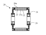
本発明に係る、独立回転式ハイブリッド永久磁石/リスかご型ケージ(Hybrid Permanent Magnet/Squirrel Cage:HPMSC)アウタロータ20と、モータシャフト14に固定結合されたリスかご型ケージ(SC)インナロータ30とを備えた電気モータ10の端面図を図1Aに示し、同側面図を図1Bに示す。電気モータ10の、図1Bの線2-2に沿った断面図を図2に示し、図1Aの線3-3に沿った断面図を図3に示す。電気モータ10は、ハウジング12と、ハウジング12に固定結合されたステータ部16と、ベアリング29に支持された(図7参照)独立回転式HPMSCアウタロータ20と、モータシャフト14に固定されたSCインナロータ30とを備える。HPMSCアウタロータ20はベアリングを介してモータシャフト14に装着され、モータシャフト14に機械的に結合せず、これと共に回転しない。
An independently rotating Hybrid Permanent Magnet/Squirrel Cage (HPMSC)
電気モータ10のハウジング12および固定式ステータ部16の、図1Bの線2-2に沿った断面図を図4に示し、図4の線5-5に沿った断面図を図5に示す。複数の固定式ステータ巻線18がステータコア19内に備わっている。ステータ巻線18は、交流(AC)信号を入力されると回転ステータ磁界を生成する。ハウジング12内に複数のベアリング13が設けられ、これがシャフト14を支えている。
A cross-sectional view of
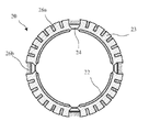
独立回転式HPMSCアウタロータ20の、図1Bの線2-2に沿った断面図を図6に示し、図6の線7-7に沿った断面図を図7に示す。HPMSCアウタロータ20は、その内面上に角度離間した複数の永久磁石22を有すると共に、外面近傍においてコア(ラミネート)23に埋め込まれた複数の角度離間した第1バー26a、26bを有する。HPMSCアウタロータ20は、例えば2、4、6、8等の、あらゆる偶数個の永久磁石22を含み得る(図12A~12D参照)。ロータコア23は永久磁石22同士の間に鉄を含まないボイド24を有する。ボイド24は、磁束バリアとなる空隙または非鉄材料からなる。永久磁石22同士の間に鉄系材料が存在すると、磁束は磁石22内にカールバックし、大半の磁束線が短絡して磁石22内に戻ってしまう。コア23は積層コアであることが好ましいが、コア23を形成する複数の薄板23aによって磁束漏れが生じることがある。薄板23aの厚さは、ロータコアラミネート23の力学的状態を保ちつつ磁束漏れが最小になるように最適化することが好ましい。バー26a、26bはそれぞれ均等に角度離間されることが好ましい。好適には永久磁石22はロータコア23の内面に接合されたネオジム磁石である。
A cross-sectional view of the independently rotating HPMSC
HPMSCアウタロータ20は小バー26aのみを備えてもよいが、構造強度をもたらす大バー26bも併せて備えることが好ましい。好適には、大バー26bは永久磁石22同士の間に角度を付けて設けられる(すなわち、放射状に配置される)。また、大バー26bの数は磁石22の数に等しいことが好ましい。好適にはボイド24は大バー26bの下方に位置する。バー26a、26bは、例えばアルミニウムなどの軽量材料で作製されることが好ましい。磁石22も軽量材料で作製されることが好ましく、好適には所定の磁力を持ちつつ軽量化が可能な希土類磁石である。バー26a、26bと永久磁石22との軽量化によりHPMSCアウタロータ20の慣性モーメントが低下して、HPMSCアウタロータ20が永久磁石22によって生じる制動トルクおよび脈動トルクに打ち勝つことができる。これによりLSPMモータよりも強力な永久磁石22とより高い効率とが得られる。バー26a、26bの抵抗とロータコア23の飽和とのバランスを最適化することで、バー26a、26bの形状、数、および寸法が例えばモータの起動などの性能に大きな影響を与えるようにすることができる。
Although the HPMSC
ロータ端キャップ28がHPMSCアウタロータ20の対向する両端に取り付けられている。端キャップ28内にはベアリング29が含まれ、このベアリングによってHPMSCアウタロータ20がモータシャフト14の周囲を自由に回転できるようになっている。ベアリング29は低摩擦ベアリング(例えば、ボールベアリングやローラベアリング)であることが好ましいが、単なるブッシング(例えば、ブロンズブッシング、オイライトブッシング、Kevlar(登録商標)ブッシングなど)であってもよい。HPMSCアウタロータ20がSCインナロータ30やモータシャフト14と機械的に結合せず、これらと共に回転しない。
Rotor end caps 28 are attached to opposite ends of the HPMSC
電気モータ10におけるSCインナロータ30の、図1Bの線2-2に沿った断面図を図8に示し、図8の線9-9に沿った断面図を図9に示す。SCインナロータ30はモータシャフト14に固定され、HPMSCアウタロータ20と協働してHPMSCアウタロータ20をモータシャフト14に同期速度で磁気結合させる。複数の第2小バー32aと複数の第2大バー32bとが第2ロータコア(ラミネート)36内に存在する。バー32a、32bは等間隔で角度離間されることが好ましいが、これは必須ではない。大バー32bはSCインナロータ30に構造強度を付与すると共に、磁束線50の指向性を助長する(図11B参照)。
A cross-sectional view of SC
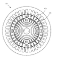
モータ10の詳細な断面図を図10に示す。また、モータ10におけるステータ16の断面図を図10Aに示し、HPMSCアウタロータ20の断面図を図10Bに示し、SCインナロータ30の断面図を図10Cに示す。ステータ16のラミネート19内には、回転ステータ磁界を生成する複数のステータ巻線18が含まれている。
A detailed cross-sectional view of
HPMSCアウタロータ20はベアリング29を通じてモータシャフトに回転式に結合しており(図7参照)、ラミネート23に埋め込まれた、小リスかご型ケージバー26aと大リスかご型ケージバー26bとを有している。永久磁石24がHPMSCアウタロータ20の内面上に設けられている。この内面はSCインナロータ30に対面している。
HPMSC
SCインナロータ30は、小バー32aと大バー32bとを備えている。磁束バリア38がラミネート36中の凹型経路に沿って延びている。磁束バリア38の外端は小バー32aにほぼ位置整合している。小バー32aと大バー32bとは共にラミネート36中にわずかに後退している。
The SC
起動時のステータ巻線18とバー26a、26bとの間の磁力線42a、および起動直後のモータ10の永久磁石22とバー32a、32bとの間の磁力線42bを図11Aに示す。磁力線42aは回転ステータ磁界に対するバー26a、26bのスリップによって生じる。磁力線42aは起動すると直ちに現れる。この理由は、HPMSCアウタロータ20は起動時には静止しており、この静止したHPMSCアウタロータ20と回転ステータ磁界との間にスリップが生じるためである。このスリップにより磁気誘導を通じてバー26に電流が発生し、この電流によりHPMSCアウタロータ20にトルクがかかってHPMSCアウタロータ20が加速される。
FIG. 11A shows the
起動のほぼ直後に、HPMSCアウタロータ20が回転を始めると、HPMSCアウタロータ20の永久磁石22とSCインナロータ30のバー32a、32bとの間のスリップが進展し、磁力線42bが形成される。磁力線42bは起動時に直ぐには現れない。これは、この磁力線によってHPMSCアウタロータ20がSCインナロータに回転式に結合して、HPMSCアウタロータ20の加速に対する抵抗が生じるためである。このことはモータ10の重要な特徴である。公知のLSPMモータでは、この抵抗は、HPMSCアウタロータ20が永久磁石による制動トルクおよび脈動トルクに打ち勝つことを妨げて、永久磁石22の磁力を制限する。このためにモータ10の効率に限界が生じている。このためモータ10は自己調整を行うが、HPMSCアウタロータ20が制動トルクおよび脈動トルクに打ち勝った後に、HPMSCアウタロータ20をSCインナロータ30とモータシャフト14とに結合するだけである。
Almost immediately after start-up, as the HPMSC
ステータ巻線18と永久磁石22との間の磁力線50であって、同期速度においてモータ10のSCインナロータ30まで入り込む磁力線50を図11Bに示す。同期速度においては、回転ステータ磁界と各バー26a、26b、32a、32bとの間のスリップは生じないため、回転ステータ磁界と各バー26a、26b、32a、32bとの電気的協働は生じない。この段階で回転ステータ磁界は永久磁石22と完全に協働し、磁束バリア38によってSCインナロータ内をガイドされる。
The
ステータ16を除いた2極形態のモータ10の磁力線を図12Aに示し、ステータ16を除いた4極形態のモータ10の磁力線を図12Bに示し、ステータ16を除いた6極形態のモータ10の磁力線を図12Cに示し、ステータ16を除いた8極形態のモータ10の磁力線を図12Dに示す。
FIG. 12A shows magnetic force lines of the 2-
本発明に係る方法を図13に示す。この方法は次の各ステップを含む。すなわち、ステップ100でステータに電流を供給し、ステップ102で回転ステータ磁界を生成し、ステップ104で回転ステータ磁界がHPMSCアウタロータのリスかご型ケージと誘導的に協働し、ステップ106で回転ステータ磁界がHPMSCアウタロータを加速し、ステップ108でHPMSCアウタロータの永久磁石が回転永久磁石磁界を生成し、ステップ110でこの永久磁石磁界が回転ステータ磁界と結合して複合回転磁界が生じ、ステップ112でこの複合回転磁界がSCインナロータのリスかご型ケージと誘導的に協働し、ステップ114で複合回転磁界がSCインナロータを加速し、ステップ116でSCインナロータが同期速度に近づき、ステップ118で、同期速度においてHPMSCアウタロータとSCインナロータとが磁気結合する。この方法の重要な特徴は、HPMSCアウタロータは回転するまでSCインナロータと結合しないため、LSPMモータにおいて永久磁石の磁力を制限する制動トルクおよび脈動トルクに打ち勝つことができることである。
A method according to the invention is shown in FIG. This method includes the following steps. Step 100 supplies current to the stator; Step 102 produces a rotating stator magnetic field; Step 104 the rotating stator magnetic field inductively cooperates with the squirrel cage of the HPMSC outer rotor; accelerates the HPMSC outer rotor, the permanent magnets of the HPMSC outer rotor produce a rotating permanent magnet magnetic field at
HPMSCアウタロータとSCインナロータとを備えたハイブリッド電気モータについて述べる。HPMSCアウタロータは、第1ロータコアに埋め込まれた複数の第1導電性リスかご型ケージバーと第2ロータコアの内面上の複数の永久磁石とを有している。また、HPMSCアウタロータはステータとSCインナロータとの間でかつモータシャフトと同軸上に設けられ、如何なる動作においてもモータシャフトと機械的に結合せず、これと共に回転しない。SCインナロータはモータシャフトに固定されかつモータシャフトと同軸に位置し、第2ロータコアと、第2ロータコアに埋め込まれた複数の第2導電性リスかご型ケージバーと、同期速度において回転ステータ磁界をSCインナロータ中でガイドする磁束バリアとを有している。当業者であれば、磁石、バー、および磁束バリアの数が本明細書記載の数と異なるが、本明細書記載の原理に基づく他の実施形態があり得ることがわかるであろう。それらの実施形態は全て本発明の範囲に包含されるものとする。 A hybrid electric motor with an HPMSC outer rotor and an SC inner rotor is described. The HPMSC outer rotor has a plurality of first conductive squirrel cage bars embedded in the first rotor core and a plurality of permanent magnets on the inner surface of the second rotor core. Also, the HPMSC outer rotor is mounted between the stator and the SC inner rotor and coaxially with the motor shaft, and is not mechanically coupled to or rotates with the motor shaft during any operation. The SC inner rotor is fixed to and coaxial with the motor shaft and has a second rotor core and a plurality of second electrically conductive squirrel cage bars embedded in the second rotor core to direct the rotating stator magnetic field to the SC inner rotor at synchronous speed. and a magnetic flux barrier guiding therein. Those skilled in the art will recognize that the number of magnets, bars, and flux barriers may vary from those described herein, but that there are other embodiments based on the principles described herein. All such embodiments are intended to be included within the scope of the present invention.
ステータ磁界と、HPMSCアウタロータ磁界と、SCインナロータ磁界との回転のタイムラインを図14に示す。 A timeline of the rotation of the stator magnetic field, the HPMSC outer rotor magnetic field and the SC inner rotor magnetic field is shown in FIG.
ハイブリッド永久磁石ヒステリシス(HPMH)アウタロータ20'を備えた、本発明の第2ハイブリッド誘導モータ10'の断面図を図15に示す。誘導型起動素子は渦電流(すなわちヒステリシス)リング60(図17参照)からなり、このリング60をHPMSCアウタロータ20のリスかご型ケージ26a、26b(図6参照)に置き換えて初期の起動トルクを与える。SCインナロータにおいて大リスかご型ケージバー32bは不要であり、ハイブリッド誘導モータ10'には図示されていない。その他の点については、ハイブリッド誘導モータ10'はハイブリッド誘導モータ10と同様である。
A cross-sectional view of a second hybrid induction motor 10' of the present invention with a hybrid permanent magnet hysteresis (HPMH) outer rotor 20' is shown in FIG. The inductive starting element consists of an eddy current (or hysteresis) ring 60 (see FIG. 17) which replaces the
HPMHアウタロータを備えたハイブリッド誘導モータ10'の側断面図を図16Aに示し、分解側断面図を図16Bに示す。 A cross-sectional side view of a hybrid induction motor 10' with an HPMH outer rotor is shown in FIG. 16A and an exploded cross-sectional view is shown in FIG. 16B.
本発明に係るHPMHアウタロータの側断面図であって渦電流リング60を示す側断面図を図17に示す。HPMHアウタロータ20'が同期速度に達すると、渦電流リング60はモータ動作に影響を及ぼさなくなる。渦電流リング60は起動素子用材料となり得る任意の導電材料からなる。この材料は、通常は硬質クロム鋼またはコバルト鋼であるが、任意の非鉄材料であってもよい。本発明のHPMHアウタロータリングの好適な材料は銅である。銅は導電性が高いために効率がよい。銀は銅よりも導電性が高くいくらか性能が優っている。アルミニウムは銅よりも導電性が低く性能が劣っている。最新のナノテクノロジや新種の高導電材料を用いることで銅よりも優れた性能が得られる可能性がある。
A cross-sectional side view of the HPMH outer rotor according to the present invention showing the
第2SCインナロータ30'の側断面図を図18に示す。SCインナロータ30'は大リスかご型ケージバー32bを有してもよいが必須ではなく、図には示されていない。その他の点については、SCインナロータ30'はSCインナロータ30と同様である。
A side sectional view of the second SC inner rotor 30' is shown in FIG. The SC inner rotor 30' may have squirrel cage bars 32b, but this is not required and is not shown in the figures. SC
本発明は電気モータの分野に産業上の利用可能性を見出している。 The present invention finds industrial applicability in the field of electric motors.
本開示の発明を特定の実施形態およびその応用を用いて説明したが、特許請求の範囲で述べた発明の範囲内で多くの修正や変形を当業者によって実施し得る。
Although the invention of the present disclosure has been described with particular embodiments and applications thereof, many modifications and variations can be made by those skilled in the art within the scope of the invention as set forth in the claims.
Claims (17)
モータハウジングと、
前記モータハウジングに固定されて回転ステータ磁界を生成するステータと、
前記モータハウジングに回転可能に接続されて、前記モータハウジングの少なくとも1つの連結用端部から負荷まで延びたモータシャフトと、
前記モータシャフトに回転式に固定されかつ前記モータシャフトと同軸上に設けられる第2ロータと、
前記ステータと前記第2ロータとの間に、かつ前記モータシャフトと同軸上に設けられ、前記モータシャフトに回転可能に機械的結合せず前記モータシャフトと共に回転しない第1ロータと、
を備え、前記第2ロータは、
第2ロータコアと、
前記第2ロータコアに埋め込まれた複数の第2リスかご型ケージバーであって、導電性で、互いに周方向に間隔を空けて設けられた複数の第2リスかご型ケージバーと、
を備え、前記第1ロータは、
第1ロータコアと、
起動時に回転ステータ磁界と協働してトルクを生成するように構成された少なくとも1つの誘導素子と、
前記少なくとも1つの誘導素子から前記第2ロータの方に径方向に離間して配される永久磁石であって、前記少なくとも1つの誘導素子と、周方向におけるある角度で、径方向に重なる永久磁石と、
を備え、前記少なくとも1つの誘導素子は前記永久磁石と前記ステータとの径方向の間に位置し、
前記第1ロータと前記第2ロータは同期動作中磁気的に結合可能である、
モータ。 A hybrid squirrel cage cage and permanent magnet motor, comprising:
a motor housing;
a stator fixed to the motor housing to generate a rotating stator magnetic field;
a motor shaft rotatably connected to the motor housing and extending from at least one coupling end of the motor housing to a load;
a second rotor rotatably fixed to and coaxial with the motor shaft;
a first rotor provided between the stator and the second rotor and coaxial with the motor shaft, not rotatably mechanically coupled to the motor shaft and not rotating with the motor shaft;
wherein the second rotor comprises
a second rotor core;
a plurality of second squirrel cage cage bars embedded in the second rotor core, the plurality of electrically conductive, circumferentially spaced second squirrel cage bars;
wherein the first rotor comprises
a first rotor core;
at least one inductive element configured to cooperate with a rotating stator magnetic field to produce a torque during start-up;
a permanent magnet radially spaced from the at least one inductive element toward the second rotor, the permanent magnet radially overlapping the at least one inductive element at an angle in the circumferential direction; When,
wherein said at least one inductive element is positioned radially between said permanent magnet and said stator;
the first rotor and the second rotor are magnetically coupleable during synchronous operation;
motor.
前記第1のグループは、周方向に間隔を空けて設けられたN個の第1大リスかご型ケージバーによって周方向に分離され、前記第1大リスかご型ケージバーは、連続する前記第1グループを分離する、
請求項1に記載のモータ。 The at least one inductive element has a plurality of circumferentially-spaced first mini-squirrel cage cage bars, the plurality of first mini-squirrel cage cage bars being divided into N first groups. and each of the first groups includes a plurality of consecutive first squirrel cage cage bars;
The first groups are circumferentially separated by N first circumferentially-spaced large squirrel cage cage bars, the first large squirrel cage cage bars being arranged in series with the first group. separate the
A motor according to claim 1.
前記第2ロータはインナーロータであり、
前記第1ロータは、前記インナーロータと前記ステータの間に位置するアウターロータである、
請求項1に記載のモータ。 The stator is positioned outside the first rotor and the second rotor,
the second rotor is an inner rotor,
The first rotor is an outer rotor positioned between the inner rotor and the stator,
A motor according to claim 1.
同期速度において、
・ 前記複数の第1リスかご型ケージバーは前記複数の第2リスかご型ケージバーに角度的に位置が合い、
・ 前記ステータから、前記複数の第1リスかご型ケージバーの間を通り、前記永久磁石を通って、前記複数の第2リスかご型ケージバーの間へと磁力線が通過する、
請求項8に記載のモータ。 said at least one inductive element comprising a plurality of first squirrel cage bars;
At synchronous speed,
- said plurality of first squirrel cage cage bars are angularly aligned with said plurality of second squirrel cage cage bars;
- magnetic field lines pass from the stator, between the plurality of first squirrel cage bars, through the permanent magnet, and between the plurality of second squirrel cage bars;
A motor according to claim 8 .
前記少なくとも1つの誘導素子は、前記第1ロータコアに埋め込まれた導電性の複数の第1小リスかご型ケージバーからなる第1グループをN個含み、前記N個の第1グループはそれぞれ、前記N個の永久磁石のうちの1つと角度的に位置が合っており、
前記少なくとも1つの誘導素子は更に、前記第1ロータコアの埋め込まれた導電性の第1大リスかご型ケージバーをN個含み、前記第1大リスかご型ケージバーはいずれも、前記第1小リスかご型ケージバーのどれよりも大きな断面を有し、前記第1大リスかご型ケージバーは、前記N個の永久磁石の間の間隙に角度的に位置が合っており、
前記N個の第1大リスかご型ケージバーはそれぞれ、前記N個の第1グループを周方向に分離している、
請求項1に記載のモータ。 the permanent magnet comprises N circumferentially spaced permanent magnets;
The at least one inductive element includes N first groups of a plurality of electrically conductive first squirrel cage cage bars embedded in the first rotor core, each of the N first groups being associated with the N angularly aligned with one of the permanent magnets,
The at least one inductive element further includes N conductive first large squirrel cage bars embedded in the first rotor core, each of the first large squirrel cage cage bars being associated with the first small squirrel cage. said first large squirrel cage cage bar being angularly aligned with the gap between said N permanent magnets;
each of the N first large squirrel cage bars circumferentially separates the N first groups;
A motor according to claim 1.
同期動作の間、前記第2小リスかご型ケージバーは、個々に前記第1小リスかご型ケージバーと位置が合い、前記第2大リスかご型ケージバーは、個々に前記第1大リスかご型ケージバーと位置が合う、
請求項10に記載のモータ。 the second squirrel cage cage bars include N groups of a plurality of second small squirrel cage cage bars and N second large squirrel cage cage bars;
During synchronous operation, the second small squirrel cage cage bars are individually aligned with the first small squirrel cage cage bars and the second large squirrel cage cage bars are individually aligned with the first large squirrel cage cage bars. aligned with
11. Motor according to claim 10 .
同期動作の間、前記複数の第2リスかご型ケージバーの各々は、前記複数の第1リスかご型ケージバーのいずれかと位置が合う、
請求項1に記載のモータ。 said at least one inductive element comprising a plurality of first squirrel cage bars;
each of the plurality of second squirrel cage cage bars aligns with one of the plurality of first squirrel cage bars during a synchronizing operation;
A motor according to claim 1.
前記N個の第1グループのそれぞれは、前記N個の永久磁石のいずれかに径方向に重なって位置する、
請求項5に記載のモータ。 the permanent magnet comprises N circumferentially spaced permanent magnets;
each of the N first groups radially overlaps one of the N permanent magnets;
A motor according to claim 5.
モータハウジングと、
前記モータハウジングに固定されて回転ステータ磁界を生成するステータと、
前記モータハウジングに回転可能に接続されて、前記モータハウジングの少なくとも1つの連結用端部から負荷まで延びたモータシャフトと、
前記モータシャフトに回転式に固定されかつ前記モータシャフトと同軸上に設けられる第2ロータと、
前記ステータと前記第2ロータとの間に、かつ前記モータシャフトと同軸上に設けられ、前記モータシャフトに回転可能に機械的結合せず如何なる動作中も前記モータシャフトと共に回転しない第1ロータとを備え、
を備え、前記第2ロータは、
第2ロータコアと、
前記第2ロータコアに埋め込まれた複数の第2リスかご型ケージバーであって、導電性で、互いに周方向に間隔を空けて設けられた複数の第2リスかご型ケージバーと、
を備え、前記第1ロータは、
第1ロータコアと、
前記第1ロータコアに埋め込まれた複数の第1リスかご型ケージバーであって、導電性で、互いに周方向に間隔を空けて設けられた複数の第1リスかご型ケージバーと、
前記第1ロータコア内に位置する複数の永久磁石であって、前記複数の第1リスかご型ケージバーから前記第2ロータの方に径方向に離れて位置し、前記複数の第1リスかご型ケージバーに、周方向におけるある角度で、径方向に重なる複数の永久磁石と、
を備え、
前記複数の第1リスかご型ケージバーは回転ステータ磁場と協働して始動時のトルクを提供するように構成され、同期動作の間、前記複数の第1リスかご型ケージバーは前記複数の第2リスかご型ケージバーに同時に角度的に位置が合うことができ、
前記複数の第1リスかご型ケージバーは前記複数の永久磁石と前記ステータの径方向の間に位置する、
モータ。 A hybrid squirrel cage cage and permanent magnet motor, comprising:
a motor housing;
a stator fixed to the motor housing to generate a rotating stator magnetic field;
a motor shaft rotatably connected to the motor housing and extending from at least one coupling end of the motor housing to a load;
a second rotor rotatably fixed to and coaxial with the motor shaft;
a first rotor disposed between said stator and said second rotor and coaxial with said motor shaft and not rotatably mechanically coupled to said motor shaft and not rotating with said motor shaft during any operation; prepared,
wherein the second rotor comprises
a second rotor core;
a plurality of second squirrel cage cage bars embedded in the second rotor core, the plurality of electrically conductive, circumferentially spaced second squirrel cage bars;
wherein the first rotor comprises
a first rotor core;
a plurality of first squirrel cage cage bars embedded in the first rotor core, the plurality of first squirrel cage cage bars being electrically conductive and circumferentially spaced from one another;
a plurality of permanent magnets located within the first rotor core, radially spaced from the plurality of first squirrel cage bars toward the second rotor, the plurality of first squirrel cage bars; a plurality of permanent magnets radially overlapping at an angle in the circumferential direction ;
with
The plurality of first squirrel cage bars are configured to cooperate with a rotating stator magnetic field to provide a starting torque, and during synchronous operation, the plurality of first squirrel cage bars are adapted to cooperate with the plurality of second squirrel cage bars. It can be angularly aligned with the squirrel cage bar at the same time,
the plurality of first squirrel cage bars are positioned radially between the plurality of permanent magnets and the stator;
motor.
前記永久磁石はN個の永久磁石からなり、
前記第1リスかご型ケージバーは複数の第1小リスかご型ケージバーを有し、前記複数の第1小リスかご型ケージバーはN個の第1グループに分割され、前記第1グループのそれぞれは、連続した前記第1小リスかご型ケージバーを複数含み、
前記第1リスかご型ケージバーの前記第1グループのそれぞれは、前記N個の永久磁石のいずれかに径方向に重なって位置する、
モータ。 15. The motor of claim 14 , wherein
The permanent magnet consists of N permanent magnets,
The first squirrel cage cage bars have a plurality of first mini squirrel cage cage bars, the plurality of first mini squirrel cage cage bars are divided into N first groups, each of the first groups comprising: including a plurality of the continuous first squirrel cage cage bars,
each of said first group of said first squirrel cage bars radially overlapping one of said N permanent magnets;
motor.
モータハウジングと、
前記モータハウジングに固定されて回転ステータ磁界を生成するステータと、
前記モータハウジングに回転可能に接続されて、前記モータハウジングの少なくとも1つの連結用端部から負荷まで延びたモータシャフトと、
前記モータシャフトに回転式に固定されかつ前記モータシャフトと同軸上に設けられる第2ロータと、
前記ステータと前記第2ロータとの間に、かつ前記モータシャフトと同軸上に設けられ、前記モータシャフトに回転可能に機械的結合せず前記モータシャフトと共に回転しない第1ロータと、
を備え、前記第2ロータは、
第2ロータコアと、
前記第2ロータコアに埋め込まれた複数の第2リスかご型ケージバーであって、導電性で、互いに周方向に間隔を空けて設けられた複数の第2リスかご型ケージバーと、
を備え、前記第1ロータは、
第1ロータコアと、
前記第1ロータコアに埋め込まれた複数の第1リスかご型ケージバーであって、導電性で互いに周方向に間隔を空けて設けられし、回転ステータ磁場と協働して始動時のトルクを提供するように構成される、第1リスかご型ケージバーと、
前記第1リスかご型ケージバーの下で、前記第2ロータに向いた前記第1ロータコアの面の上に位置する永久磁石と、
を備え、同期動作の間、ステータ磁力線は、前記複数の第1リスかご型ケージバーのうちの連続する前記第1リスかご型ケージバーの間、及び、前記複数の第2リスかご型ケージバーのうちの連続する前記第2リスかご型ケージバーの間を通過する、モータ。 A hybrid squirrel cage cage and permanent magnet motor, comprising:
a motor housing;
a stator fixed to the motor housing to generate a rotating stator magnetic field;
a motor shaft rotatably connected to the motor housing and extending from at least one coupling end of the motor housing to a load;
a second rotor rotatably fixed to and coaxial with the motor shaft;
a first rotor provided between the stator and the second rotor and coaxial with the motor shaft, not rotatably mechanically coupled to the motor shaft and not rotating with the motor shaft;
wherein the second rotor comprises
a second rotor core;
a plurality of second squirrel cage cage bars embedded in the second rotor core, the plurality of electrically conductive, circumferentially spaced second squirrel cage bars;
wherein the first rotor comprises
a first rotor core;
A plurality of first squirrel cage bars embedded in the first rotor core, electrically conductive and circumferentially spaced from one another, for cooperating with rotating stator magnetic fields to provide torque at start-up. a first squirrel cage cage bar configured to:
permanent magnets positioned below the first squirrel cage bars and on a face of the first rotor core facing the second rotor;
and during synchronous operation, the stator magnetic field lines are distributed between successive first squirrel cage bars of the plurality of first squirrel cage bars and among the second squirrel cage bars of the plurality of A motor that passes between successive said second squirrel cage bars.
Applications Claiming Priority (3)
| Application Number | Priority Date | Filing Date | Title |
|---|---|---|---|
| US15/438,023 | 2017-02-21 | ||
| US15/438,023 US10998802B2 (en) | 2017-02-21 | 2017-02-21 | Hybrid induction motor with self aligning hybrid induction/permanent magnet rotor |
| PCT/US2018/018956 WO2018156582A1 (en) | 2017-02-21 | 2018-02-21 | Hybrid induction motor with self aligning hybrid induction/permanent magnet rotor |
Publications (3)
| Publication Number | Publication Date |
|---|---|
| JP2020508631A JP2020508631A (en) | 2020-03-19 |
| JP2020508631A5 JP2020508631A5 (en) | 2021-04-15 |
| JP7158397B2 true JP7158397B2 (en) | 2022-10-21 |
Family
ID=62490424
Family Applications (1)
| Application Number | Title | Priority Date | Filing Date |
|---|---|---|---|
| JP2019544851A Active JP7158397B2 (en) | 2017-02-21 | 2018-02-21 | Hybrid induction motor with self-regulating hybrid induction/permanent magnet rotor |
Country Status (14)
| Country | Link |
|---|---|
| US (1) | US10998802B2 (en) |
| EP (1) | EP3586433A4 (en) |
| JP (1) | JP7158397B2 (en) |
| KR (1) | KR102630362B1 (en) |
| CN (1) | CN108462349B (en) |
| AR (1) | AR111384A1 (en) |
| AU (1) | AU2018225543A1 (en) |
| BR (1) | BR112019017362B1 (en) |
| CA (1) | CA3053913A1 (en) |
| HK (1) | HK1258540A1 (en) |
| MX (1) | MX2019009933A (en) |
| RU (1) | RU2755208C2 (en) |
| TW (1) | TWI785008B (en) |
| WO (1) | WO2018156582A1 (en) |
Families Citing this family (8)
| Publication number | Priority date | Publication date | Assignee | Title |
|---|---|---|---|---|
| US20190068044A1 (en) * | 2010-01-25 | 2019-02-28 | Svetozar B. Petrovich | In Evolution of Gravity Fields |
| US10998802B2 (en) * | 2017-02-21 | 2021-05-04 | Louis J. Finkle | Hybrid induction motor with self aligning hybrid induction/permanent magnet rotor |
| JP6709712B2 (en) * | 2016-10-07 | 2020-06-17 | 東芝産業機器システム株式会社 | Synchronous reluctance type rotating electric machine |
| PT3588753T (en) * | 2018-06-29 | 2021-05-14 | Abb Schweiz Ag | An electric induction machine |
| CN110492710B (en) * | 2019-09-20 | 2021-02-26 | 齐鲁工业大学 | Double-rotor generator and control method thereof |
| KR102509568B1 (en) * | 2020-11-26 | 2023-03-10 | 한양대학교 산학협력단 | Rotor of line start synchronous reluctacne motor with q-axis slot structure for improving power characteristic |
| KR102547221B1 (en) * | 2021-07-08 | 2023-06-23 | 에스제이글로벌 주식회사 | rotor for line start permanent magnet assisted synchronous reluctance motor, and manufacturing method for thereof |
| CN113691093B (en) * | 2021-07-30 | 2022-12-09 | 齐鲁工业大学 | Outer rotor permanent magnet induction motor and working method |
Citations (1)
| Publication number | Priority date | Publication date | Assignee | Title |
|---|---|---|---|---|
| US20130278096A1 (en) | 2012-04-20 | 2013-10-24 | Louis J. Finkle | Hybrid Induction Motor with Self Aligning Permanent Magnet Inner Rotor |
Family Cites Families (84)
| Publication number | Priority date | Publication date | Assignee | Title |
|---|---|---|---|---|
| GB495813A (en) | 1936-05-27 | 1938-11-21 | Jakob Bohli | Magneto electric machines |
| US2209558A (en) | 1937-04-22 | 1940-07-30 | Karl Otto Goettsch | Magnetic clamping appliance |
| US2243616A (en) | 1937-12-08 | 1941-05-27 | Bing Julius | Lifting magnet |
| US2287286A (en) | 1938-08-13 | 1942-06-23 | Karl Otto Goettsch | Magnetic chuck |
| US2558540A (en) | 1948-03-23 | 1951-06-26 | Bell Telephone Labor Inc | Electromagnetic motor |
| US2864017A (en) * | 1955-11-28 | 1958-12-09 | Waltscheff Dimo Dimitroff | Inducto-motive power apparatus with a plurality of rotors |
| US3445699A (en) | 1965-08-31 | 1969-05-20 | Reuland Electric Co | Multirotor induction motor |
| US3459981A (en) | 1966-06-01 | 1969-08-05 | Mallory & Co Inc P R | Shaded pole synchronous motor |
| US3758800A (en) * | 1972-01-24 | 1973-09-11 | Gen Electric | Reluctance synchronous motors and rotors for same |
| JPS572692B2 (en) | 1972-02-23 | 1982-01-18 | ||
| US4151431A (en) | 1973-12-06 | 1979-04-24 | Johnson Howard R | Permanent magnet motor |
| JPS5147208A (en) | 1974-10-21 | 1976-04-22 | Nippon Telegraph & Telephone | PARUSUMOOTATEISHIJINO SHINDOKYUSHUSOCHI |
| IT1108126B (en) | 1977-11-30 | 1985-12-02 | Fischer Ag Georg | ALLOY FOR NON MAGENTIZABLE AUSTENITIC STEEL JETS |
| YU41934B (en) | 1979-08-03 | 1988-02-29 | Baermann Max | Switehing-in permanent - magnetbrake |
| US4508998A (en) | 1981-02-09 | 1985-04-02 | David H. Rush | Brushless disc-type DC motor or generator |
| US4578609A (en) | 1982-09-29 | 1986-03-25 | The Garrett Corporation | Permanent magnet dynamoelectric machine |
| JPS62117558A (en) | 1985-11-18 | 1987-05-29 | 東邦機工株式会社 | Wheelchair freely rising and falling along upstairs |
| WO1988005976A1 (en) | 1987-02-04 | 1988-08-11 | Franklin's Magnetic Generator Corp. | Dynamomagnetic machine |
| SU1631672A1 (en) * | 1987-08-24 | 1991-02-28 | Томский политехнический институт им.С.М.Кирова | Synchronous electric motor with permanent magnets |
| US4829205A (en) | 1987-12-04 | 1989-05-09 | Lindgren Theodore D | Dual-rotary induction motor with stationary field winding |
| US5508576A (en) | 1990-07-12 | 1996-04-16 | Seiko Epson Corporation | Rotor for brushless electromotor |
| FR2675299B1 (en) | 1991-04-10 | 1994-09-16 | Braillon Cie | MAGNETIC CARRIER WITH PERMANENT MAGNETS. |
| JPH04331445A (en) | 1991-05-01 | 1992-11-19 | Honda Motor Co Ltd | Induction motor |
| JP3033621B2 (en) | 1991-08-28 | 2000-04-17 | 株式会社佐竹製作所 | Brushless induction synchronous motor |
| JP2968918B2 (en) | 1993-09-16 | 1999-11-02 | 弘平 湊 | Magnetic rotating device |
| JPH07203644A (en) | 1993-12-29 | 1995-08-04 | Tokai Rubber Ind Ltd | Rotary device |
| DE4421594A1 (en) | 1994-06-21 | 1996-01-04 | Bernhard Kraser | Air-gap induction variation device for rotary or linear electrical machine |
| JP3269346B2 (en) | 1995-08-24 | 2002-03-25 | トヨタ自動車株式会社 | Permanent magnet motor |
| US5861700A (en) * | 1996-04-30 | 1999-01-19 | Samsung Electronics Co., Ltd. | Rotor for an induction motor |
| RU2153755C2 (en) * | 1997-08-12 | 2000-07-27 | Общество с ограниченной ответственностью "Веста-Электрон" | Synchronous-asynchronous electric motor with short- circuited winding of rotor |
| JPH11146645A (en) | 1997-11-07 | 1999-05-28 | Toshiba Tec Corp | Power supply equipment |
| JPH11146615A (en) | 1997-11-11 | 1999-05-28 | Matsushita Electric Ind Co Ltd | Reluctance motor |
| US5886443A (en) | 1997-12-03 | 1999-03-23 | General Electric Canada Inc. | Spark suppression of induction type rotors of dynamoelectric machines |
| JPH11178298A (en) | 1997-12-15 | 1999-07-02 | Toshiba Corp | Stator core for permanent magnet-type motor and permanent magnet-type motor |
| JPH11341757A (en) | 1998-05-21 | 1999-12-10 | Toyota Motor Corp | Motor, power transmission apparatus, and hybrid vehicle |
| EP2276154A1 (en) | 1999-07-16 | 2011-01-19 | Panasonic Corporation | Permanent magnet synchronous motor |
| US6376959B1 (en) | 1999-10-21 | 2002-04-23 | The United States Of America As Represented By The Secretary Of The Army | Mangle magnetic structure |
| JP3879412B2 (en) | 2001-02-28 | 2007-02-14 | 株式会社日立製作所 | Power generation system |
| JP2002272067A (en) | 2001-03-15 | 2002-09-20 | Techno Takatsuki Co Ltd | Squirrel-cage rotor and motor using the squirrel-cage rotor |
| JP3695344B2 (en) | 2001-04-16 | 2005-09-14 | 日産自動車株式会社 | Rotating electric machine |
| JP4619585B2 (en) | 2001-09-06 | 2011-01-26 | 株式会社東芝 | Reluctance type rotating electrical machine |
| US20040041481A1 (en) | 2002-08-27 | 2004-03-04 | Jin-Hu Kuo | Magnetism driven power machine |
| JP4120347B2 (en) | 2002-10-08 | 2008-07-16 | 日産自動車株式会社 | Rotating electric machine |
| JP2004140978A (en) | 2002-10-21 | 2004-05-13 | Mitsubishi Heavy Ind Ltd | Squirrel cage induction rotor, and its manufacturing method |
| CN1726629B (en) | 2002-12-12 | 2010-11-03 | Lg电子株式会社 | Rotor for line-start reluctance motor |
| WO2004088817A2 (en) | 2003-03-28 | 2004-10-14 | John Bates | Improved efficiency magnetic motor |
| US6864773B2 (en) | 2003-04-04 | 2005-03-08 | Applied Materials, Inc. | Variable field magnet apparatus |
| JP4069796B2 (en) | 2003-05-08 | 2008-04-02 | 日産自動車株式会社 | Magnetic circuit controller for multi-axis multilayer motor |
| GB0312486D0 (en) | 2003-05-30 | 2003-07-09 | Univ Bath | Improvements in or relating to electromotive machines |
| KR100545694B1 (en) | 2003-07-23 | 2006-01-24 | 가부시키가이샤 야스기 세이사쿠쇼 | Punching device for printing discs |
| KR100565220B1 (en) | 2003-10-14 | 2006-03-30 | 엘지전자 주식회사 | Reluctance motor |
| US7088011B2 (en) | 2003-11-21 | 2006-08-08 | Smith Raymond W | Motor-generator system with a current control feedback loop |
| JP2005210826A (en) | 2004-01-22 | 2005-08-04 | Fujitsu General Ltd | Electric motor |
| JP3996919B2 (en) | 2004-08-20 | 2007-10-24 | 信越化学工業株式会社 | Permanent magnet motor |
| KR100631551B1 (en) * | 2004-12-21 | 2006-10-09 | 엘지전자 주식회사 | Twin magnet hybride induction motor |
| KR100619769B1 (en) | 2005-02-04 | 2006-09-11 | 엘지전자 주식회사 | Hybrid type induction motor with function of reverse rotation prevention |
| JP2006288183A (en) | 2005-03-09 | 2006-10-19 | Nissan Motor Co Ltd | Dynamo-electric motor |
| JP4434045B2 (en) | 2005-03-14 | 2010-03-17 | 株式会社日立製作所 | Rotating electric machine and wind power generation system |
| KR100652596B1 (en) * | 2005-04-11 | 2006-12-01 | 엘지전자 주식회사 | Twin magnet hybride induction motor |
| JP4969064B2 (en) | 2005-06-14 | 2012-07-04 | 日立アプライアンス株式会社 | Electric motor rotor and electric motor |
| KR100690700B1 (en) * | 2006-01-23 | 2007-03-12 | 엘지전자 주식회사 | Single phase induction motor capable of controling variable speed |
| JP4882715B2 (en) | 2006-12-11 | 2012-02-22 | ダイキン工業株式会社 | Electric motor and control method thereof |
| DE102006060986A1 (en) | 2006-12-20 | 2008-06-26 | Robert Bosch Gmbh | Magnetic torque limiter |
| JP5157182B2 (en) | 2007-01-30 | 2013-03-06 | 日産自動車株式会社 | Reluctance motor rotor and reluctance motor including the same |
| US7923881B2 (en) | 2007-05-04 | 2011-04-12 | A.O. Smith Corporation | Interior permanent magnet motor and rotor |
| US7851962B1 (en) | 2007-06-14 | 2010-12-14 | Williams Kevin R | Induction motor utilizing dual stators and a double squirrel cage motor |
| GB0810096D0 (en) | 2008-06-03 | 2008-07-09 | Magnomatics Ltd | Electrical machines |
| WO2009155467A2 (en) | 2008-06-18 | 2009-12-23 | Duffey Christopher K | Variable speed synchronous generator |
| GB0817046D0 (en) | 2008-09-18 | 2008-10-22 | Rolls Royce Plc | Magnectic Gear Arrangement |
| JP2011061933A (en) | 2009-09-08 | 2011-03-24 | Toshiba Corp | Permanent magnet type rotary electric machine |
| US8156697B2 (en) | 2009-10-15 | 2012-04-17 | Sunlink Corporation | Photovoltaic module mounting system |
| US8288908B2 (en) | 2009-10-30 | 2012-10-16 | Finkle Louis J | Reconfigurable inductive to synchronous motor |
| US8390162B2 (en) | 2009-10-30 | 2013-03-05 | Louis J. Finkle | Reconfigurable inductive to synchronous motor |
| US8097993B2 (en) | 2009-10-30 | 2012-01-17 | Finkle Louis J | Electric motor and/or generator with mechanically tuneable permanent magnetic field |
| US8072108B2 (en) | 2009-10-30 | 2011-12-06 | Finkle Louis J | Electric motor or generator with mechanically tuneable permanent magnetic field |
| JP5835215B2 (en) | 2010-05-17 | 2015-12-24 | 日立金属株式会社 | Coupling device |
| CN102868268A (en) | 2011-07-03 | 2013-01-09 | 余虹锦 | Novel air gap magnetic field electromagnetic modulation permanent magnet motor with double squirrel cage structure |
| KR101310529B1 (en) | 2011-09-01 | 2013-09-23 | 삼성전기주식회사 | Switched reluctance motor |
| JP5702692B2 (en) | 2011-09-13 | 2015-04-15 | 日本信号株式会社 | Tipping machine |
| JP5712882B2 (en) * | 2011-09-28 | 2015-05-07 | 株式会社豊田自動織機 | Electric motor for electric compressor |
| DE102013102184A1 (en) | 2012-03-09 | 2013-09-12 | Denso Corporation | Magnetic modulation motor and electrical transmission |
| US9923440B2 (en) | 2014-01-09 | 2018-03-20 | Motor Generator Technology, Inc. | Hybrid electric motor with self aligning permanent magnet and squirrel cage rotors |
| US9923439B2 (en) * | 2014-01-09 | 2018-03-20 | Motor Generator Technology, Inc. | Hybrid electric motor with self aligning permanent magnet and squirrel cage rotors |
| US10998802B2 (en) * | 2017-02-21 | 2021-05-04 | Louis J. Finkle | Hybrid induction motor with self aligning hybrid induction/permanent magnet rotor |
-
2017
- 2017-02-21 US US15/438,023 patent/US10998802B2/en active Active
-
2018
- 2018-02-13 CN CN201810150855.0A patent/CN108462349B/en active Active
- 2018-02-14 AR ARP180100340A patent/AR111384A1/en active IP Right Grant
- 2018-02-14 TW TW107105446A patent/TWI785008B/en active
- 2018-02-21 KR KR1020197027190A patent/KR102630362B1/en active IP Right Grant
- 2018-02-21 JP JP2019544851A patent/JP7158397B2/en active Active
- 2018-02-21 EP EP18756698.9A patent/EP3586433A4/en active Pending
- 2018-02-21 RU RU2019129732A patent/RU2755208C2/en active
- 2018-02-21 MX MX2019009933A patent/MX2019009933A/en unknown
- 2018-02-21 CA CA3053913A patent/CA3053913A1/en active Pending
- 2018-02-21 AU AU2018225543A patent/AU2018225543A1/en not_active Abandoned
- 2018-02-21 WO PCT/US2018/018956 patent/WO2018156582A1/en unknown
- 2018-02-21 BR BR112019017362-5A patent/BR112019017362B1/en active IP Right Grant
-
2019
- 2019-01-18 HK HK19100895.5A patent/HK1258540A1/en unknown
Patent Citations (1)
| Publication number | Priority date | Publication date | Assignee | Title |
|---|---|---|---|---|
| US20130278096A1 (en) | 2012-04-20 | 2013-10-24 | Louis J. Finkle | Hybrid Induction Motor with Self Aligning Permanent Magnet Inner Rotor |
Also Published As
| Publication number | Publication date |
|---|---|
| KR20190115086A (en) | 2019-10-10 |
| TWI785008B (en) | 2022-12-01 |
| CN108462349B (en) | 2021-08-27 |
| US10998802B2 (en) | 2021-05-04 |
| RU2019129732A (en) | 2021-03-24 |
| EP3586433A1 (en) | 2020-01-01 |
| BR112019017362B1 (en) | 2023-11-21 |
| KR102630362B1 (en) | 2024-01-26 |
| RU2019129732A3 (en) | 2021-07-06 |
| TW201832453A (en) | 2018-09-01 |
| MX2019009933A (en) | 2020-07-14 |
| BR112019017362A2 (en) | 2020-03-31 |
| EP3586433A4 (en) | 2020-12-09 |
| CN108462349A (en) | 2018-08-28 |
| US20180166959A1 (en) | 2018-06-14 |
| HK1258540A1 (en) | 2019-11-15 |
| JP2020508631A (en) | 2020-03-19 |
| CA3053913A1 (en) | 2018-08-30 |
| RU2755208C2 (en) | 2021-09-14 |
| WO2018156582A1 (en) | 2018-08-30 |
| AR111384A1 (en) | 2019-07-10 |
| AU2018225543A1 (en) | 2019-09-05 |
Similar Documents
| Publication | Publication Date | Title |
|---|---|---|
| JP7158397B2 (en) | Hybrid induction motor with self-regulating hybrid induction/permanent magnet rotor | |
| US10749390B2 (en) | Line-start synchronous reluctance motor with improved performance | |
| EP1675250B1 (en) | Hybrid induction motor | |
| JP6596002B2 (en) | Hybrid electric motor with self-aligning permanent magnet saddle rotor | |
| US10476363B2 (en) | Hybrid electric motor with self aligning permanent magnet and squirrel cage dual rotors magnetically coupled with permeant magnets and bars at synchronous speed | |
| EP1713161A1 (en) | Hybrid induction motor | |
| CN212462910U (en) | Rotor for an electric machine with asymmetrical poles and transverse magnets | |
| US9923439B2 (en) | Hybrid electric motor with self aligning permanent magnet and squirrel cage rotors | |
| US10651764B2 (en) | End ring and rotor bar for line start permanent magnet motor | |
| EP3208918A1 (en) | Double stator-type rotary machine | |
| US20220200375A1 (en) | Four-pole synchronous reluctance motor | |
| US9620999B2 (en) | High conductivity rotor cage for line start permanent magnet motor | |
| GB2494898A (en) | Field weakening in permanent magnet rotor | |
| US20210257893A1 (en) | Hybrid Induction Eddy Current Ring Motor with Self Aligning Hybrid Induction/Permanent Magnet Rotor | |
| JP6661960B2 (en) | Self-starting permanent magnet motor | |
| WO2016080192A1 (en) | Interior magnet rotary electric machine | |
| JP2007020322A (en) | Axial-gap rotary electric machine |
Legal Events
| Date | Code | Title | Description |
|---|---|---|---|
| A621 | Written request for application examination |
Free format text: JAPANESE INTERMEDIATE CODE: A621 Effective date: 20210215 |
|
| A521 | Request for written amendment filed |
Free format text: JAPANESE INTERMEDIATE CODE: A523 Effective date: 20210225 |
|
| A131 | Notification of reasons for refusal |
Free format text: JAPANESE INTERMEDIATE CODE: A131 Effective date: 20220316 |
|
| A521 | Request for written amendment filed |
Free format text: JAPANESE INTERMEDIATE CODE: A523 Effective date: 20220530 |
|
| TRDD | Decision of grant or rejection written | ||
| A01 | Written decision to grant a patent or to grant a registration (utility model) |
Free format text: JAPANESE INTERMEDIATE CODE: A01 Effective date: 20220901 |
|
| A601 | Written request for extension of time |
Free format text: JAPANESE INTERMEDIATE CODE: A601 Effective date: 20220902 |
|
| A61 | First payment of annual fees (during grant procedure) |
Free format text: JAPANESE INTERMEDIATE CODE: A61 Effective date: 20221011 |
|
| R150 | Certificate of patent or registration of utility model |
Ref document number: 7158397 Country of ref document: JP Free format text: JAPANESE INTERMEDIATE CODE: R150 |