JP7158395B2 - Variable focus imaging device based on polarization conversion - Google Patents
Variable focus imaging device based on polarization conversion Download PDFInfo
- Publication number
- JP7158395B2 JP7158395B2 JP2019543946A JP2019543946A JP7158395B2 JP 7158395 B2 JP7158395 B2 JP 7158395B2 JP 2019543946 A JP2019543946 A JP 2019543946A JP 2019543946 A JP2019543946 A JP 2019543946A JP 7158395 B2 JP7158395 B2 JP 7158395B2
- Authority
- JP
- Japan
- Prior art keywords
- polarization
- light
- waveguide
- notch reflector
- display device
- Prior art date
- Legal status (The legal status is an assumption and is not a legal conclusion. Google has not performed a legal analysis and makes no representation as to the accuracy of the status listed.)
- Active
Links
- 230000010287 polarization Effects 0.000 title claims description 368
- 238000003384 imaging method Methods 0.000 title description 22
- 238000006243 chemical reaction Methods 0.000 title description 17
- 239000004986 Cholesteric liquid crystals (ChLC) Substances 0.000 claims description 319
- 230000003287 optical effect Effects 0.000 claims description 256
- 239000004973 liquid crystal related substance Substances 0.000 claims description 166
- 238000010168 coupling process Methods 0.000 claims description 46
- 238000005859 coupling reaction Methods 0.000 claims description 46
- 230000008878 coupling Effects 0.000 claims description 14
- 230000001965 increasing effect Effects 0.000 claims description 8
- 210000001508 eye Anatomy 0.000 description 159
- 239000011295 pitch Substances 0.000 description 71
- 239000000463 material Substances 0.000 description 38
- 230000000694 effects Effects 0.000 description 25
- 230000001902 propagating effect Effects 0.000 description 20
- 238000012545 processing Methods 0.000 description 19
- 150000001875 compounds Chemical class 0.000 description 18
- 239000000758 substrate Substances 0.000 description 16
- 230000003190 augmentative effect Effects 0.000 description 15
- 239000003086 colorant Substances 0.000 description 15
- 238000000034 method Methods 0.000 description 13
- 230000008859 change Effects 0.000 description 11
- 239000000835 fiber Substances 0.000 description 10
- 230000004308 accommodation Effects 0.000 description 9
- 230000005684 electric field Effects 0.000 description 9
- 230000006870 function Effects 0.000 description 9
- 238000004891 communication Methods 0.000 description 8
- 239000011521 glass Substances 0.000 description 8
- 210000001747 pupil Anatomy 0.000 description 8
- 230000000712 assembly Effects 0.000 description 7
- 238000000429 assembly Methods 0.000 description 7
- 230000008901 benefit Effects 0.000 description 7
- 238000006116 polymerization reaction Methods 0.000 description 7
- 239000004990 Smectic liquid crystal Substances 0.000 description 6
- 230000003098 cholesteric effect Effects 0.000 description 6
- 230000007423 decrease Effects 0.000 description 6
- 230000003247 decreasing effect Effects 0.000 description 6
- 230000008447 perception Effects 0.000 description 6
- 125000004386 diacrylate group Chemical group 0.000 description 5
- 238000005516 engineering process Methods 0.000 description 5
- 238000000605 extraction Methods 0.000 description 5
- 230000033001 locomotion Effects 0.000 description 5
- 229920000307 polymer substrate Polymers 0.000 description 5
- 230000004044 response Effects 0.000 description 5
- 238000009281 ultraviolet germicidal irradiation Methods 0.000 description 5
- 230000000007 visual effect Effects 0.000 description 5
- 101100232265 Candida albicans (strain SC5314 / ATCC MYA-2876) HWP2 gene Proteins 0.000 description 4
- 210000004556 brain Anatomy 0.000 description 4
- 238000005253 cladding Methods 0.000 description 4
- 238000000576 coating method Methods 0.000 description 4
- 239000000203 mixture Substances 0.000 description 4
- 230000035790 physiological processes and functions Effects 0.000 description 4
- 229920000642 polymer Polymers 0.000 description 4
- 230000008569 process Effects 0.000 description 4
- 239000007787 solid Substances 0.000 description 4
- 238000001228 spectrum Methods 0.000 description 4
- 101100126085 Escherichia coli incB gene Proteins 0.000 description 3
- 241000976924 Inca Species 0.000 description 3
- 230000004075 alteration Effects 0.000 description 3
- 238000013459 approach Methods 0.000 description 3
- 230000003542 behavioural effect Effects 0.000 description 3
- 230000002996 emotional effect Effects 0.000 description 3
- 230000007613 environmental effect Effects 0.000 description 3
- 210000000720 eyelash Anatomy 0.000 description 3
- 230000004438 eyesight Effects 0.000 description 3
- 238000010438 heat treatment Methods 0.000 description 3
- 101150001870 incC gene Proteins 0.000 description 3
- 238000002347 injection Methods 0.000 description 3
- 239000007924 injection Substances 0.000 description 3
- 239000007788 liquid Substances 0.000 description 3
- 238000002156 mixing Methods 0.000 description 3
- 239000000178 monomer Substances 0.000 description 3
- 230000003595 spectral effect Effects 0.000 description 3
- 230000003068 static effect Effects 0.000 description 3
- 241000473391 Archosargus rhomboidalis Species 0.000 description 2
- 238000003491 array Methods 0.000 description 2
- 230000005540 biological transmission Effects 0.000 description 2
- 238000009826 distribution Methods 0.000 description 2
- 210000000613 ear canal Anatomy 0.000 description 2
- 230000001747 exhibiting effect Effects 0.000 description 2
- 239000000284 extract Substances 0.000 description 2
- 210000000744 eyelid Anatomy 0.000 description 2
- 239000012530 fluid Substances 0.000 description 2
- 210000003128 head Anatomy 0.000 description 2
- 208000013057 hereditary mucoepithelial dysplasia Diseases 0.000 description 2
- 101150064356 incD gene Proteins 0.000 description 2
- 238000010348 incorporation Methods 0.000 description 2
- 238000004519 manufacturing process Methods 0.000 description 2
- 238000005259 measurement Methods 0.000 description 2
- 239000013307 optical fiber Substances 0.000 description 2
- 230000000737 periodic effect Effects 0.000 description 2
- 230000002093 peripheral effect Effects 0.000 description 2
- 230000002829 reductive effect Effects 0.000 description 2
- 230000011514 reflex Effects 0.000 description 2
- 210000001525 retina Anatomy 0.000 description 2
- 230000002441 reversible effect Effects 0.000 description 2
- 238000004088 simulation Methods 0.000 description 2
- 239000000126 substance Substances 0.000 description 2
- 230000001131 transforming effect Effects 0.000 description 2
- 241000256837 Apidae Species 0.000 description 1
- 206010027646 Miosis Diseases 0.000 description 1
- 208000006550 Mydriasis Diseases 0.000 description 1
- 239000004988 Nematic liquid crystal Substances 0.000 description 1
- 239000004983 Polymer Dispersed Liquid Crystal Substances 0.000 description 1
- XUIMIQQOPSSXEZ-UHFFFAOYSA-N Silicon Chemical compound [Si] XUIMIQQOPSSXEZ-UHFFFAOYSA-N 0.000 description 1
- 241000153282 Theope Species 0.000 description 1
- 239000004974 Thermotropic liquid crystal Substances 0.000 description 1
- 206010047571 Visual impairment Diseases 0.000 description 1
- 238000010521 absorption reaction Methods 0.000 description 1
- 238000004364 calculation method Methods 0.000 description 1
- 239000013626 chemical specie Substances 0.000 description 1
- 239000011248 coating agent Substances 0.000 description 1
- 230000001186 cumulative effect Effects 0.000 description 1
- 238000013500 data storage Methods 0.000 description 1
- 230000001419 dependent effect Effects 0.000 description 1
- 238000001514 detection method Methods 0.000 description 1
- 238000011161 development Methods 0.000 description 1
- 238000009792 diffusion process Methods 0.000 description 1
- 239000006185 dispersion Substances 0.000 description 1
- 210000000887 face Anatomy 0.000 description 1
- 230000008921 facial expression Effects 0.000 description 1
- 239000010408 film Substances 0.000 description 1
- 238000005286 illumination Methods 0.000 description 1
- 230000008676 import Effects 0.000 description 1
- 238000011065 in-situ storage Methods 0.000 description 1
- 230000001939 inductive effect Effects 0.000 description 1
- 238000002329 infrared spectrum Methods 0.000 description 1
- 238000002955 isolation Methods 0.000 description 1
- 230000002535 lyotropic effect Effects 0.000 description 1
- 239000012528 membrane Substances 0.000 description 1
- 230000003547 miosis Effects 0.000 description 1
- 238000012986 modification Methods 0.000 description 1
- 230000004048 modification Effects 0.000 description 1
- 230000006855 networking Effects 0.000 description 1
- 210000001331 nose Anatomy 0.000 description 1
- 238000012856 packing Methods 0.000 description 1
- 230000036961 partial effect Effects 0.000 description 1
- 230000000704 physical effect Effects 0.000 description 1
- 230000004962 physiological condition Effects 0.000 description 1
- 229920000515 polycarbonate Polymers 0.000 description 1
- 239000004417 polycarbonate Substances 0.000 description 1
- 230000005855 radiation Effects 0.000 description 1
- 230000009467 reduction Effects 0.000 description 1
- 238000002310 reflectometry Methods 0.000 description 1
- 230000029058 respiratory gaseous exchange Effects 0.000 description 1
- 229910052594 sapphire Inorganic materials 0.000 description 1
- 239000010980 sapphire Substances 0.000 description 1
- 229910052710 silicon Inorganic materials 0.000 description 1
- 239000010703 silicon Substances 0.000 description 1
- 125000006850 spacer group Chemical group 0.000 description 1
- 230000000638 stimulation Effects 0.000 description 1
- 238000006467 substitution reaction Methods 0.000 description 1
- 238000002560 therapeutic procedure Methods 0.000 description 1
- 239000010409 thin film Substances 0.000 description 1
- 230000001052 transient effect Effects 0.000 description 1
- 238000001429 visible spectrum Methods 0.000 description 1
- 230000016776 visual perception Effects 0.000 description 1
- 238000012800 visualization Methods 0.000 description 1
Images


Classifications
-
- G—PHYSICS
- G02—OPTICS
- G02B—OPTICAL ELEMENTS, SYSTEMS OR APPARATUS
- G02B26/00—Optical devices or arrangements for the control of light using movable or deformable optical elements
- G02B26/08—Optical devices or arrangements for the control of light using movable or deformable optical elements for controlling the direction of light
- G02B26/0816—Optical devices or arrangements for the control of light using movable or deformable optical elements for controlling the direction of light by means of one or more reflecting elements
- G02B26/0825—Optical devices or arrangements for the control of light using movable or deformable optical elements for controlling the direction of light by means of one or more reflecting elements the reflecting element being a flexible sheet or membrane, e.g. for varying the focus
-
- G—PHYSICS
- G02—OPTICS
- G02B—OPTICAL ELEMENTS, SYSTEMS OR APPARATUS
- G02B27/00—Optical systems or apparatus not provided for by any of the groups G02B1/00 - G02B26/00, G02B30/00
- G02B27/01—Head-up displays
- G02B27/017—Head mounted
- G02B27/0172—Head mounted characterised by optical features
-
- G—PHYSICS
- G02—OPTICS
- G02B—OPTICAL ELEMENTS, SYSTEMS OR APPARATUS
- G02B30/00—Optical systems or apparatus for producing three-dimensional [3D] effects, e.g. stereoscopic images
-
- G—PHYSICS
- G02—OPTICS
- G02B—OPTICAL ELEMENTS, SYSTEMS OR APPARATUS
- G02B5/00—Optical elements other than lenses
- G02B5/20—Filters
-
- G—PHYSICS
- G02—OPTICS
- G02B—OPTICAL ELEMENTS, SYSTEMS OR APPARATUS
- G02B5/00—Optical elements other than lenses
- G02B5/30—Polarising elements
-
- G—PHYSICS
- G02—OPTICS
- G02B—OPTICAL ELEMENTS, SYSTEMS OR APPARATUS
- G02B6/00—Light guides; Structural details of arrangements comprising light guides and other optical elements, e.g. couplings
- G02B6/0001—Light guides; Structural details of arrangements comprising light guides and other optical elements, e.g. couplings specially adapted for lighting devices or systems
- G02B6/0011—Light guides; Structural details of arrangements comprising light guides and other optical elements, e.g. couplings specially adapted for lighting devices or systems the light guides being planar or of plate-like form
- G02B6/0013—Means for improving the coupling-in of light from the light source into the light guide
- G02B6/0023—Means for improving the coupling-in of light from the light source into the light guide provided by one optical element, or plurality thereof, placed between the light guide and the light source, or around the light source
- G02B6/0026—Wavelength selective element, sheet or layer, e.g. filter or grating
-
- G—PHYSICS
- G02—OPTICS
- G02B—OPTICAL ELEMENTS, SYSTEMS OR APPARATUS
- G02B6/00—Light guides; Structural details of arrangements comprising light guides and other optical elements, e.g. couplings
- G02B6/0001—Light guides; Structural details of arrangements comprising light guides and other optical elements, e.g. couplings specially adapted for lighting devices or systems
- G02B6/0011—Light guides; Structural details of arrangements comprising light guides and other optical elements, e.g. couplings specially adapted for lighting devices or systems the light guides being planar or of plate-like form
- G02B6/0033—Means for improving the coupling-out of light from the light guide
- G02B6/005—Means for improving the coupling-out of light from the light guide provided by one optical element, or plurality thereof, placed on the light output side of the light guide
- G02B6/0055—Reflecting element, sheet or layer
-
- G—PHYSICS
- G02—OPTICS
- G02B—OPTICAL ELEMENTS, SYSTEMS OR APPARATUS
- G02B6/00—Light guides; Structural details of arrangements comprising light guides and other optical elements, e.g. couplings
- G02B6/0001—Light guides; Structural details of arrangements comprising light guides and other optical elements, e.g. couplings specially adapted for lighting devices or systems
- G02B6/0011—Light guides; Structural details of arrangements comprising light guides and other optical elements, e.g. couplings specially adapted for lighting devices or systems the light guides being planar or of plate-like form
- G02B6/0033—Means for improving the coupling-out of light from the light guide
- G02B6/0056—Means for improving the coupling-out of light from the light guide for producing polarisation effects, e.g. by a surface with polarizing properties or by an additional polarizing elements
-
- G—PHYSICS
- G02—OPTICS
- G02B—OPTICAL ELEMENTS, SYSTEMS OR APPARATUS
- G02B6/00—Light guides; Structural details of arrangements comprising light guides and other optical elements, e.g. couplings
- G02B6/0001—Light guides; Structural details of arrangements comprising light guides and other optical elements, e.g. couplings specially adapted for lighting devices or systems
- G02B6/0011—Light guides; Structural details of arrangements comprising light guides and other optical elements, e.g. couplings specially adapted for lighting devices or systems the light guides being planar or of plate-like form
- G02B6/0075—Arrangements of multiple light guides
- G02B6/0076—Stacked arrangements of multiple light guides of the same or different cross-sectional area
-
- G—PHYSICS
- G02—OPTICS
- G02B—OPTICAL ELEMENTS, SYSTEMS OR APPARATUS
- G02B6/00—Light guides; Structural details of arrangements comprising light guides and other optical elements, e.g. couplings
- G02B6/0001—Light guides; Structural details of arrangements comprising light guides and other optical elements, e.g. couplings specially adapted for lighting devices or systems
- G02B6/0011—Light guides; Structural details of arrangements comprising light guides and other optical elements, e.g. couplings specially adapted for lighting devices or systems the light guides being planar or of plate-like form
- G02B6/0081—Mechanical or electrical aspects of the light guide and light source in the lighting device peculiar to the adaptation to planar light guides, e.g. concerning packaging
- G02B6/0086—Positioning aspects
- G02B6/0088—Positioning aspects of the light guide or other optical sheets in the package
-
- G—PHYSICS
- G02—OPTICS
- G02F—OPTICAL DEVICES OR ARRANGEMENTS FOR THE CONTROL OF LIGHT BY MODIFICATION OF THE OPTICAL PROPERTIES OF THE MEDIA OF THE ELEMENTS INVOLVED THEREIN; NON-LINEAR OPTICS; FREQUENCY-CHANGING OF LIGHT; OPTICAL LOGIC ELEMENTS; OPTICAL ANALOGUE/DIGITAL CONVERTERS
- G02F1/00—Devices or arrangements for the control of the intensity, colour, phase, polarisation or direction of light arriving from an independent light source, e.g. switching, gating or modulating; Non-linear optics
- G02F1/01—Devices or arrangements for the control of the intensity, colour, phase, polarisation or direction of light arriving from an independent light source, e.g. switching, gating or modulating; Non-linear optics for the control of the intensity, phase, polarisation or colour
- G02F1/13—Devices or arrangements for the control of the intensity, colour, phase, polarisation or direction of light arriving from an independent light source, e.g. switching, gating or modulating; Non-linear optics for the control of the intensity, phase, polarisation or colour based on liquid crystals, e.g. single liquid crystal display cells
- G02F1/133—Constructional arrangements; Operation of liquid crystal cells; Circuit arrangements
- G02F1/13306—Circuit arrangements or driving methods for the control of single liquid crystal cells
-
- G—PHYSICS
- G02—OPTICS
- G02F—OPTICAL DEVICES OR ARRANGEMENTS FOR THE CONTROL OF LIGHT BY MODIFICATION OF THE OPTICAL PROPERTIES OF THE MEDIA OF THE ELEMENTS INVOLVED THEREIN; NON-LINEAR OPTICS; FREQUENCY-CHANGING OF LIGHT; OPTICAL LOGIC ELEMENTS; OPTICAL ANALOGUE/DIGITAL CONVERTERS
- G02F1/00—Devices or arrangements for the control of the intensity, colour, phase, polarisation or direction of light arriving from an independent light source, e.g. switching, gating or modulating; Non-linear optics
- G02F1/01—Devices or arrangements for the control of the intensity, colour, phase, polarisation or direction of light arriving from an independent light source, e.g. switching, gating or modulating; Non-linear optics for the control of the intensity, phase, polarisation or colour
- G02F1/13—Devices or arrangements for the control of the intensity, colour, phase, polarisation or direction of light arriving from an independent light source, e.g. switching, gating or modulating; Non-linear optics for the control of the intensity, phase, polarisation or colour based on liquid crystals, e.g. single liquid crystal display cells
- G02F1/137—Devices or arrangements for the control of the intensity, colour, phase, polarisation or direction of light arriving from an independent light source, e.g. switching, gating or modulating; Non-linear optics for the control of the intensity, phase, polarisation or colour based on liquid crystals, e.g. single liquid crystal display cells characterised by the electro-optical or magneto-optical effect, e.g. field-induced phase transition, orientation effect, guest-host interaction or dynamic scattering
- G02F1/13718—Devices or arrangements for the control of the intensity, colour, phase, polarisation or direction of light arriving from an independent light source, e.g. switching, gating or modulating; Non-linear optics for the control of the intensity, phase, polarisation or colour based on liquid crystals, e.g. single liquid crystal display cells characterised by the electro-optical or magneto-optical effect, e.g. field-induced phase transition, orientation effect, guest-host interaction or dynamic scattering based on a change of the texture state of a cholesteric liquid crystal
-
- G—PHYSICS
- G02—OPTICS
- G02F—OPTICAL DEVICES OR ARRANGEMENTS FOR THE CONTROL OF LIGHT BY MODIFICATION OF THE OPTICAL PROPERTIES OF THE MEDIA OF THE ELEMENTS INVOLVED THEREIN; NON-LINEAR OPTICS; FREQUENCY-CHANGING OF LIGHT; OPTICAL LOGIC ELEMENTS; OPTICAL ANALOGUE/DIGITAL CONVERTERS
- G02F1/00—Devices or arrangements for the control of the intensity, colour, phase, polarisation or direction of light arriving from an independent light source, e.g. switching, gating or modulating; Non-linear optics
- G02F1/29—Devices or arrangements for the control of the intensity, colour, phase, polarisation or direction of light arriving from an independent light source, e.g. switching, gating or modulating; Non-linear optics for the control of the position or the direction of light beams, i.e. deflection
-
- G—PHYSICS
- G02—OPTICS
- G02F—OPTICAL DEVICES OR ARRANGEMENTS FOR THE CONTROL OF LIGHT BY MODIFICATION OF THE OPTICAL PROPERTIES OF THE MEDIA OF THE ELEMENTS INVOLVED THEREIN; NON-LINEAR OPTICS; FREQUENCY-CHANGING OF LIGHT; OPTICAL LOGIC ELEMENTS; OPTICAL ANALOGUE/DIGITAL CONVERTERS
- G02F2203/00—Function characteristic
- G02F2203/07—Polarisation dependent
Description
(参照による援用)
本願は、2017年2月23日に出願され“VARIABLE-FOCUS VIRTUAL IMAGE DEVICES”と題された米国仮特許出願第62/462,850号の利益を主張するものであり、該米国仮特許出願は、その全体が参照により本明細書中に援用される。この仮特許出願は、以下のセクションを含み、これらの両方が、参照により援用され、本願の一部を形成している。
1.セクションI:“DISPLAY SYSTEM WITH VARIABLE POWER REFLECTOR”(「可変屈折力反射体を有するディスプレイシステム」)と題された出願の部分に対する明細書および図面
2.セクションII:“VARIABLE-FOCUS VIRTUAL IMAGE DEVICES BASED ON POLARIZATION CONVERSION”(「偏光変換に基づく可変焦点仮想画像デバイス」)と題された明細書および図面
(INCORPORATION BY REFERENCE)
This application claims the benefit of U.S. Provisional Patent Application No. 62/462,850, filed February 23, 2017, entitled "VARIABLE-FOCUS VIRTUAL IMAGE DEVICES," which U.S. Provisional Patent Application , which is incorporated herein by reference in its entirety. This provisional patent application contains the following sections, both of which are incorporated by reference and form part of this application.
1. Section I: Specification and Drawings for the portion of the application entitled "DISPLAY SYSTEM WITH VARIABLE POWER REFLECTOR"2. Section II: Specification and Drawings Entitled "VARIABLE-FOCUS VIRTUAL IMAGE DEVICES BASED ON POLARIZATION CONVERSION"
セクションIおよびセクションIIの両方は、可変焦点または可変屈折力デバイスおよびこれらのデバイスに関連付けられた特徴を議論しており、両セクションは、本願の議論の一部を等しく形成している。したがって、セクションIに議論されている種々の特徴、要素、構造、方法等は、任意の組み合わせにおいて、セクションIIに議論されている特徴、要素、構造、方法等とともに用いられ得、組み合わされ得、組み込まれ得、または、別様にこれらと両立し得る。同様に、セクションIIに議論されている種々の特徴、要素、構造、方法等は、任意の組み合わせにおいて、セクションIにおいて議論されている特徴、要素、構造、方法等とともに用いられ得、組み合わされ得、組み込まれ得、または、別様に両立し得る。 Both Section I and Section II discuss variable focus or variable power devices and features associated with these devices, and both sections equally form part of the discussion of this application. Thus, the various features, elements, structures, methods, etc. discussed in Section I can be used and combined in any combination with the features, elements, structures, methods, etc. discussed in Section II; may be incorporated or otherwise compatible with them. Similarly, the various features, elements, structures, methods, etc. discussed in Section II can be used and combined with the features, elements, structures, methods, etc. discussed in Section I in any combination. , may be incorporated, or otherwise compatible.
本願はまた、以下の特許出願の各々の全体を参照により援用するものである:米国出願第14/555,585号(出願日2014年11月27日);米国出願第14/690,401号(出願日2015年4月18日);米国出願第14/212,961号(出願日2014年3月14日);および米国出願第14/331,218号(出願日2014年7月14日)。 This application also incorporates by reference in its entirety each of the following patent applications: U.S. Application No. 14/555,585 (filed Nov. 27, 2014); U.S. Application No. 14/690,401; (filed April 18, 2015); U.S. Application No. 14/212,961 (filed March 14, 2014); and U.S. Application No. 14/331,218 (filed July 14, 2014). ).
(分野)
本開示は、ディスプレイシステムに関し、より具体的には、少なくとも部分的に偏光変換に基づく回折デバイス備える、拡張現実ディスプレイシステムに関する。
(field)
The present disclosure relates to display systems, and more particularly to augmented reality display systems comprising diffraction devices based at least in part on polarization conversion.
現代のコンピューティングおよびディスプレイ技術は、いわゆる「仮想現実」または「拡張現実」体験のためのシステムの開発を促進しており、デジタル的に再現された画像またはその一部が、現実であるように見える、またはそのように知覚され得る様式でユーザに提示される。仮想現実、すなわち、「VR」シナリオは、典型的には、他の実際の実世界の視覚的入力に対する透過性を伴わずに、デジタルまたは仮想画像情報の提示を伴い、拡張現実または「AR」シナリオは、典型的には、ユーザの周囲の実際の世界の可視化に対する拡張としてのデジタルまたは仮想画像情報の提示を伴う。複合現実または「MR」シナリオは、一種のARシナリオであって、典型的には、自然世界の中に統合され、それに応答する、仮想オブジェクトを伴う。例えば、MRシナリオでは、AR画像コンテンツは、実世界内のオブジェクトによってブロックされて見える、または別様にそれと相互作用するように知覚され得る。 Modern computing and display technologies are spurring the development of systems for so-called "virtual reality" or "augmented reality" experiences, in which digitally reproduced images, or portions thereof, appear as if they were real. Presented to the user in a manner that can be seen or perceived as such. Virtual Reality, or “VR” scenarios typically involve the presentation of digital or virtual image information without transparency to other real-world visual inputs, augmented reality or “AR” Scenarios typically involve the presentation of digital or virtual image information as an extension to the visualization of the real world around the user. A mixed reality or "MR" scenario is a type of AR scenario that typically involves virtual objects integrated into and responsive to the natural world. For example, in MR scenarios, AR image content may be perceived as being blocked by or otherwise interacting with objects in the real world.
図1を参照すると、拡張現実場面1が、描写され、AR技術のユーザには、人々、木々、背景における建物、およびコンクリートプラットフォーム1120を特徴とする、実世界公園状設定1100が見える。これらのアイテムに加え、AR技術のユーザはまた、これらの要素1130、1110が実世界内に存在しないにもかかわらず、実世界プラットフォーム1120上に立っているロボット像1110と、マルハナバチの擬人化のように見える、飛んでいる漫画のようなアバタキャラクタ1130等の「仮想コンテンツ」を「見ている」と知覚する。ヒトの視知覚系は、複雑であって、他の仮想または実世界画像要素間における仮想画像要素の快適で、自然のような感覚で、かつ豊かな提示を促進する、AR技術の生産は、困難である。
Referring to FIG. 1, an augmented
本明細書に開示されるシステムおよび方法は、ARまたはVR技術に関連する種々の課題に対処する。 The systems and methods disclosed herein address various challenges associated with AR or VR technology.
本願は、可変屈折力を提供するために採用され得る、システムおよび方法の議論を含む。可変焦点または可変屈折力デバイスは、画像が異なる深度から生じた場合のように画像を投影する、特定の頭部搭載型ディスプレイデバイスにおいて用途を見出し得る。頭部搭載型ディスプレイデバイス内の光学要素の屈折力を変化させることによって、頭部搭載型ディスプレイデバイスの装着者に提示される画像は、装着者から異なる距離に位置した場合のように見える。可変焦点または可変屈折力光学デバイスは、したがって、画像コンテンツがユーザに対して異なる場所に位置する場合のように、異なる画像コンテンツを表示させるように変調されることができる。いくつかの可変屈折力要素は、可動膜を備える、反射体を備える。他の可変屈折力要素は、切替可能液晶要素を使用して屈折力レベルを切り替え得る、液晶切替可能デバイスを備える。本明細書に説明されるいくつかの可変焦点デバイスは、光の偏光性質を利用し、1つの焦点から別の焦点に切り替わることを促進する。 This application includes a discussion of systems and methods that can be employed to provide variable optical power. Variable focus or variable power devices may find use in certain head mounted display devices that project images as if they originated from different depths. By varying the refractive power of the optical elements within the head mounted display device, the images presented to the wearer of the head mounted display device appear as if they were positioned at different distances from the wearer. A variable focus or variable power optical device can thus be modulated to display different image content, such as when the image content is located at different locations relative to the user. Some variable power elements comprise reflectors comprising movable membranes. Other variable power elements comprise liquid crystal switchable devices that can switch power levels using switchable liquid crystal elements. Some variable focus devices described herein take advantage of the polarizing properties of light to facilitate switching from one focus to another.
ある側面では、ディスプレイデバイスは、導波管の主要表面と平行方向に全内部反射下で可視光を伝搬するように構成される、導波管と、導波管上に形成され、導波管の主要表面に対する法線の方向に可視光の一部を外部結合するように構成される、外部結合要素とを備える。ディスプレイデバイスは、加えて、導波管の第1の側に配置され、第2の偏光を有する可視光の一部を透過させながら、第1の偏光を有する可視光を反射させるように構成される、偏光選択的ノッチ反射体を備える。ディスプレイデバイスはさらに、導波管の第2の側に配置され、第1の偏光を有する可視光および第2の偏光を有する可視光を反射させるように構成される、偏光無依存ノッチ反射体を備え、偏光無依存ノッチ反射体は、そこから反射する可視光の偏光を変換するように構成される。 In one aspect, a display device comprises a waveguide configured to propagate visible light under total internal reflection in a direction parallel to a major surface of the waveguide; an out-coupling element configured to out-couple a portion of the visible light in a direction normal to the major surface of the. The display device is additionally arranged on the first side of the waveguide and configured to reflect visible light having the first polarization while transmitting a portion of the visible light having the second polarization. a polarization selective notch reflector. The display device further includes a polarization independent notch reflector disposed on a second side of the waveguide and configured to reflect visible light having the first polarization and visible light having the second polarization. The polarization independent notch reflector is configured to convert the polarization of visible light reflected therefrom.
別の側面では、ディスプレイデバイスは、第1の切替可能レンズと第2の切替可能レンズとの間に介在される導波デバイスを備え、導波デバイスは、それぞれ、複数のキラル構造を備える、1つ以上のコレステリック液晶(CLC)層を備え、各キラル構造は、層深度方向に延在し、第1の回転方向に連続的に回転される、複数の液晶分子を備え、キラル構造の液晶分子の配列は、1つ以上のCLC層が入射光をブラッグ反射させるように構成されるように、層深度方向と垂直な側方方向に周期的に変動する。導波デバイスは、加えて、1つ以上のCLC層にわたって形成され、導波管の主要表面と平行方向に全内部反射(TIR)下で可視光を伝搬するように、かつ可視光を、1つ以上のCLC層に、またはそこから光学的に結合するように構成される、1つ以上の導波管を含む。 In another aspect, a display device comprises a waveguide device interposed between a first switchable lens and a second switchable lens, each waveguide device comprising a plurality of chiral structures. comprising one or more cholesteric liquid crystal (CLC) layers, each chiral structure comprising a plurality of liquid crystal molecules extending in a layer depth direction and continuously rotated in a first rotation direction, the liquid crystal molecules of the chiral structure varies periodically in the lateral direction perpendicular to the layer depth direction such that one or more CLC layers are configured to Bragg reflect incident light. The waveguide device is additionally formed over one or more CLC layers to propagate visible light under total internal reflection (TIR) in a direction parallel to the major surface of the waveguide, and to transmit visible light to 1 It includes one or more waveguides configured to optically couple to or from one or more CLC layers.
別の側面では、画像をユーザの眼に表示するように構成されるディスプレイデバイスは、光学ディスプレイを備える。光学ディスプレイは、前方側と、後方側とを有し、後方側は、前方側よりもユーザの眼に近い。光学ディスプレイは、後方側に向かって波長範囲を有する光を出力するように構成される。第1のノッチ反射体は、光学ディスプレイの後方に配置され、第1のノッチ反射体は、光学ディスプレイから出力される、波長範囲を有する光を反射させるように構成される。第2のノッチ反射体は、光学ディスプレイの前方に配置され、第2のノッチ反射体は、波長範囲を有する光を反射させるように構成される。第1のノッチ反射体は、第1の偏光を有する光を実質的に透過させ、第1の偏光と異なる第2の偏光を有する光を実質的に反射させるように構成される。第2のノッチ反射体は、第2の偏光を有する、後方面上に入射する光を、第1の偏光に変換するように、かつ光を後方に再指向するように構成される。 In another aspect, a display device configured to display an image to a user's eye comprises an optical display. The optical display has a front side and a rear side, the rear side being closer to the user's eyes than the front side. The optical display is configured to output light having a wavelength range towards the rear side. A first notch reflector is positioned behind the optical display, the first notch reflector configured to reflect light having a wavelength range output from the optical display. A second notch reflector is positioned in front of the optical display, the second notch reflector configured to reflect light having a wavelength range. The first notch reflector is configured to substantially transmit light having a first polarization and substantially reflect light having a second polarization different from the first polarization. The second notch reflector is configured to convert light having a second polarization incident on the rear surface to the first polarization and redirect the light rearward.
別の側面では、動的集束ディスプレイシステムは、第1の円偏光状態で円偏光を出力するように構成される、ディスプレイを備える。ディスプレイは、光学軸に沿って配置され、前方側と、後方側とを有し、後方側は、前方側よりもユーザの眼に近く、光学ディスプレイは、後方側に向かって波長範囲を有する光を出力するように構成される。第1の切替可能光学要素は、光学軸に沿って配置され、第1の切替可能光学要素は、第1の切替可能光学要素を通して透過される光の円偏光状態を、第1の円偏光状態から第2の異なる円偏光状態に変化させるように構成される。第1のコレステリック液晶(CLC)レンズは、光学軸に沿って第1の切替可能光学要素の前方に配置される。第2の切替可能光学要素は、光学軸に沿って第1のCLCレンズの前方に配置され、第2の切替可能光学要素は、第2の切替可能光学要素を通して透過される光の円偏光状態を、第1の円偏光状態から第2の異なる円偏光状態に変化させるように構成される。第2のCLCレンズは、光学軸に沿って第2の切替可能光学要素の前方に配置される。コントローラは、第1および第2の切替可能光学要素の状態を電子的に切り替え、第1のCLCレンズまたは第2のCLCレンズのいずれかを動的に選択するように構成される。 In another aspect, a dynamic focusing display system comprises a display configured to output circularly polarized light in a first circular polarization state. The display is positioned along the optical axis and has a front side and a rear side, the rear side being closer to the user's eye than the front side, the optical display directing light having a wavelength range towards the rear side. is configured to output A first switchable optical element is disposed along the optical axis, the first switchable optical element converting the circular polarization state of light transmitted through the first switchable optical element to a first circular polarization state to a second different circular polarization state. A first cholesteric liquid crystal (CLC) lens is positioned in front of the first switchable optical element along the optical axis. A second switchable optical element is positioned in front of the first CLC lens along the optical axis, the second switchable optical element adjusting the circular polarization state of light transmitted through the second switchable optical element. from a first circular polarization state to a second different circular polarization state. A second CLC lens is positioned in front of the second switchable optical element along the optical axis. A controller is configured to electronically switch states of the first and second switchable optical elements to dynamically select either the first CLC lens or the second CLC lens.
別の側面では、ウェアラブル拡張現実頭部搭載型ディスプレイシステムは、頭部搭載型システムを装着した装着者の前方の世界から装着者の眼の中に光を通過させるように構成される。ウェアラブル拡張現実頭部搭載型ディスプレイシステムは、光を出力し、画像を形成するように構成される、光学ディスプレイと、該ディスプレイから該光を受光するように配置される、1つ以上の導波管と、該1つ以上の導波管が、前方側と、後方側とを有し、該後方側が、該前方側よりも該眼に近いように、該眼の前方に導波管を配置するように構成される、フレームと、該1つ以上の導波管の該前方側に配置される、コレステリック液晶(CLC)反射体であって、該CLC反射体は、電気信号の印加に応じて調節可能である、屈折力または焦点深度を有するように構成される、CLC反射体と、1つ以上の導波管から光を抽出し、該導波管内で伝搬する該光の少なくとも一部をCLC反射体に指向するように、該1つ以上の導波管に対して配置される、1つ以上の外部結合要素であって、該光は、ディスプレイからの画像を装着者の眼の中に提示するように、該CLC反射体から該導波管を通して戻るように、かつ該眼の中に指向される、1つ以上の外部結合要素とを備える。 In another aspect, a wearable augmented reality head-mounted display system is configured to pass light from the world in front of the wearer wearing the head-mounted system into the wearer's eyes. A wearable augmented reality head mounted display system comprises an optical display configured to output light and form an image, and one or more waveguides arranged to receive the light from the display. Placing a waveguide in front of the eye such that the tube and the one or more waveguides have an anterior side and a posterior side, the posterior side being closer to the eye than the anterior side. and a cholesteric liquid crystal (CLC) reflector disposed on the front side of the one or more waveguides, the CLC reflector responsive to the application of an electrical signal to and a CLC reflector configured to have a refractive power or depth of focus that is adjustable by the optical fiber and at least a portion of the light that extracts light from one or more waveguides and propagates within the waveguides. one or more out-coupling elements positioned relative to the one or more waveguides to direct light to the CLC reflector, the light directing the image from the display to the wearer's eye. and one or more outcoupling elements directed from the CLC reflector back through the waveguide and into the eye, as shown in.
別の側面では、ディスプレイデバイスは、導波管の主要表面と平行方向に全内部反射下で可視光を伝搬するように、かつ主要表面に対する法線の方向に可視光を外部結合するように構成される、導波管を備える。ノッチ反射体は、第1の偏光を有する可視光を反射させるように構成され、ノッチ反射体は、1つ以上のコレステリック液晶(CLC)層を備え、CLC層はそれぞれ、複数のキラル構造を備え、キラル構造はそれぞれ、層深度方向に延在し、第1の回転方向に連続的に回転される、複数の液晶分子を備え、キラル構造の液晶分子の配列は、1つ以上のCLC層が入射光をブラッグ反射させるように構成されるように、層深度方向と垂直な側方方向に周期的に変動する。 In another aspect, the display device is configured to propagate visible light under total internal reflection in a direction parallel to a major surface of the waveguide and to outcouple visible light in a direction normal to the major surface. and a waveguide. The notch reflector is configured to reflect visible light having a first polarization, the notch reflector comprising one or more cholesteric liquid crystal (CLC) layers, each CLC layer comprising a plurality of chiral structures. , the chiral structure comprises a plurality of liquid crystal molecules each extending in the layer depth direction and continuously rotated in the first rotation direction, wherein the alignment of the liquid crystal molecules in the chiral structure is such that the one or more CLC layers are It varies periodically in the lateral direction perpendicular to the layer depth direction so as to be configured to Bragg reflect incident light.
本明細書に説明される主題の1つ以上の実装の詳細は、付随の図面および下記の説明に記載される。他の特徴、側面、および利点は、説明、図面、および請求項から明白となるであろう。本概要または以下の詳細な説明のいずれも、本発明主題の範囲を定義または限定することを主張するものではない。
本発明は、例えば、以下を提供する。
(項目1)
ディスプレイデバイスであって、
導波管の主要表面と平行方向に全内部反射下で可視光を伝搬するように構成される導波管と、
外部結合要素であって、前記外部結合要素は、前記導波管上に形成され、前記導波管の主要表面に対する法線の方向に前記可視光の一部を外部結合するように構成される、外部結合要素と、
偏光選択的ノッチ反射体であって、前記偏光選択的ノッチ反射体は、前記導波管の第1の側に配置され、第2の偏光を有する可視光を透過させながら、第1の偏光を有する可視光を反射させるように構成される、偏光選択的ノッチ反射体と、
偏光無依存ノッチ反射体であって、前記偏光無依存ノッチ反射体は、前記導波管の第2の側に配置され、前記第1の偏光を有する可視光および前記第2の偏光を有する可視光を反射させるように構成され、前記偏光無依存ノッチ反射体は、そこから反射する可視光の偏光を変換するように構成される、偏光無依存ノッチ反射体と
を備える、ディスプレイデバイス。
(項目2)
前記偏光選択的ノッチ反射体および前記偏光無依存ノッチ反射体はそれぞれ、波長範囲外の波長を有する光を透過させながら、赤色、緑色、または青色光のうちの1つに対応する波長範囲内の波長を有する可視光を反射させるように構成される、項目1に記載のディスプレイデバイス。
(項目3)
前記偏光選択的ノッチ反射体は、1つ以上のコレステリック液晶(CLC)層を備える、項目1に記載のディスプレイデバイス。
(項目4)
前記1つ以上のCLC層はそれぞれ、複数のキラル構造を備え、
前記キラル構造はそれぞれ、複数の液晶分子を備え、前記複数の液晶分子は、少なくとも螺旋ピッチによって、層深度方向に延在し、第1の回転方向に連続的に回転され、
前記螺旋ピッチは、前記第1の回転方向における完全1回転による前記キラル構造の液晶分子の正味回転角度に対応する前記層深度方向における長さであり、
前記キラル構造の液晶分子の配列は、前記層深度方向と垂直な側方方向に周期的に変動する、
項目3に記載のディスプレイデバイス。
(項目5)
前記第1の偏光は、第1の円偏光であり、前記第2の偏光は、第2の円偏光である、項目3に記載のディスプレイデバイス。
(項目6)
第1の4分の1波長板と、第2の4分の1波長板とをさらに備え、前記偏光無依存ノッチ反射体は、前記第1の4分の1波長板と前記導波管との間に介在され、前記偏光選択的ノッチ反射体は、前記導波管と前記第2の4分の1波長板との間に介在される、項目1に記載のディスプレイデバイス。
(項目7)
第1の線形偏光レンズと、第2の線形偏光レンズとをさらに備え、前記第1の4分の1波長板は、前記第1の線形偏光レンズと前記偏光無依存ノッチ反射体との間に介在され、前記第2の4分の1波長板は、前記偏光選択的ノッチ反射体と前記第2の線形偏光レンズとの間に介在される、項目6に記載のディスプレイデバイス。
(項目8)
前記偏光無依存ノッチ反射体および前記偏光選択的ノッチ反射体の外側に配置される、第1のパンチャラトナムベリー(PB)レンズと、第2のパンチャラトナムベリー(PB)レンズとをさらに備える、項目1に記載のディスプレイデバイス。
(項目9)
前記偏光無依存ノッチ反射体と前記導波管との間に介在される第1の4分の1波長板をさらに備える、項目1に記載のディスプレイデバイス。
(項目10)
第2の4分の1波長板をさらに備え、前記偏光無依存ノッチ反射体は、前記第1の4分の1波長板と前記第2の4分の1波長板との間に介在される、項目9に記載のディスプレイデバイス。
(項目11)
第1の線形偏光レンズと、第2の線形偏光レンズとをさらに備え、前記第1の4分の1波長板は、前記第1の線形偏光レンズと前記偏光無依存ノッチ反射体との間に介在され、前記偏光選択的ノッチ反射体は、前記導波管と前記第2の線形偏光レンズとの間に介在される、項目10に記載のディスプレイデバイス。
(項目12)
前記偏光無依存ノッチ反射体および前記偏光選択的ノッチ反射体の外側に配置される第1のパンチャラトナムベリー(PB)レンズと、第2のパンチャラトナムベリー(PB)レンズと、前記第2のPBレンズと前記偏光選択的ノッチ反射体との間に介在される第2の4分の1波長板とをさらに備える、項目9に記載のディスプレイデバイス。
(項目13)
画像をユーザの眼に表示するように構成されるディスプレイデバイスであって、前記ディスプレイデバイスは、
光学ディスプレイであって、前記光学ディスプレイは、前方側と、後方側とを備え、前記後方側は、前記前方側よりも前記ユーザの眼に近く、前記光学ディスプレイは、前記後方側に向かって波長範囲を有する光を出力するように構成される、光学ディスプレイと、
前記光学ディスプレイの後方に配置される第1のノッチ反射体であって、前記第1のノッチ反射体は、前記光学ディスプレイから出力される前記波長範囲を有する光を反射させるように構成される、第1のノッチ反射体と、
前記光学ディスプレイの前方に配置される第2のノッチ反射体であって、前記第2のノッチ反射体は、前記波長範囲を有する光を反射させるように構成される、第2のノッチ反射体と
を備え、
前記第1のノッチ反射体は、第1の偏光を有する光を実質的に透過させ、前記第1の偏光と異なる第2の偏光を有する光を実質的に反射させるように構成され、
前記第2のノッチ反射体は、前記第2の偏光を有する後方面上に入射する光を前記第1の偏光に変換するように、かつ、前記光を後方に再指向するように構成される、
ディスプレイデバイス。
(項目14)
前記第1のノッチ反射体は、コレステリック液晶(CLC)格子(CLCG)を備える、項目13に記載のディスプレイデバイス。
(項目15)
前記第1のノッチ反射体は、多層を備え、前記第2のノッチ反射体は、非偏光ノッチ反射体と、4分の1波長板とを備える、項目23に記載のディスプレイデバイス。
(項目16)
前記第1のノッチ反射体の後方に配置される第1の可変焦点レンズと、前記第2のノッチ反射体の前方に配置される第2の可変焦点レンズとをさらに備え、前記第2の可変焦点レンズの第2の光学特性は、前記第1の可変焦点レンズの第1の光学特性を補償する、項目13に記載のディスプレイデバイス。
(項目17)
前記第1の可変焦点レンズおよび前記第2の可変焦点レンズはそれぞれ、線形偏光レンズを備える、項目16に記載のディスプレイデバイス。
(項目18)
前記第1の可変焦点レンズおよび前記第2の可変焦点レンズはそれぞれ、パンチャラトナムベリー(PB)位相レンズを備える、項目16に記載のディスプレイデバイス。
(項目19)
前記PB位相レンズによって導入される空間オフセットを補償するように構成される空間オフセット補償器をさらに備える、項目18に記載のディスプレイデバイス。
(項目20)
ディスプレイデバイスであって、
導波管であって、前記導波管は、前記導波管の主要表面と平行方向に全内部反射下で可視光を伝搬するように、かつ、前記主要表面に対する法線の方向に前記可視光を外部結合するように構成される、導波管と、
第1の偏光を有する可視光を反射させるように構成されるノッチ反射体であって、前記ノッチ反射体は、1つ以上のコレステリック液晶(CLC)層を備え、前記CLC層はそれぞれ、複数のキラル構造を備え、前記キラル構造はそれぞれ、複数の液晶分子を備え、前記複数の液晶分子は、層深度方向に延在し、第1の回転方向に連続的に回転され、前記キラル構造の液晶分子の配列は、前記1つ以上のCLC層が入射光をブラッグ反射させるように構成されるように、前記層深度方向と垂直な側方方向に周期的に変動する、ノッチ反射体と
を備える、ディスプレイデバイス。
(項目21)
前記導波管は、選択的に前記ノッチ反射体に向かって前記可視光を外部結合するように構成される、項目20に記載のディスプレイデバイス。
(項目22)
前記ノッチ反射体は、変形可能ミラーを備え、前記変形可能ミラーは、その上に形成された前記1つ以上のCLC層を有する、項目20に記載のディスプレイデバイス。
(項目23)
前記1つ以上のCLC層のうちの異なるものは、波長範囲外の波長を有する光を透過させるように構成されながら、赤色、緑色、または青色光のうちの異なるものに対応する波長範囲内の波長を有する可視光を反射させるように構成される、項目20に記載のディスプレイデバイス。
(項目24)
前記CLC層のキラル構造はそれぞれ、少なくとも螺旋ピッチによって、層深度方向に延在する複数の液晶分子を備え、前記1つ以上のCLC層のうちの異なるものは、異なる螺旋ピッチを有する、項目20に記載のディスプレイデバイス。
(項目25)
前記1つ以上のCLC層のうちの異なるものは、実質的に同一の屈折力を有する、項目20に記載のディスプレイデバイス。
(項目26)
前記ディスプレイデバイスは、複数のノッチ反射体を備え、前記ノッチ反射体はそれぞれ、第1の偏光を有する可視光を反射させるように構成され、前記ノッチ反射体はそれぞれ、1つ以上のコレステリック液晶(CLC)層を備え、前記CLC層はそれぞれ、複数のキラル構造を備え、前記キラル構造はそれぞれ、複数の液晶分子を備え、前記複数の液晶分子は、層深度方向に延在し、第1の回転方向に連続的に回転され、前記キラル構造の液晶分子の配列は、1つ以上のCLC層が入射光をブラッグ反射させるように構成されるように、前記層深度方向と垂直な側方方向に周期的に変動する、項目20に記載のディスプレイデバイス。
(項目27)
前記複数のノッチ反射体のうちの異なるものは、異なる屈折力を有する、項目26に記載のディスプレイデバイス。
(項目28)
前記複数のノッチ反射体のうちのそれぞれに対応する2分の1波長板をさらに備える、項目26に記載のディスプレイデバイス。
Details of one or more implementations of the subject matter described in this specification are set forth in the accompanying drawings and the description below. Other features, aspects, and advantages will be apparent from the description, drawings, and claims. Neither this summary nor the following detailed description is intended to define or limit the scope of the inventive subject matter.
The present invention provides, for example, the following.
(Item 1)
a display device,
a waveguide configured to propagate visible light under total internal reflection in a direction parallel to a major surface of the waveguide;
An out-coupling element formed on the waveguide and configured to out-couple a portion of the visible light in a direction normal to a major surface of the waveguide. , the outer coupling element, and
A polarization-selective notch reflector, said polarization-selective notch reflector disposed on a first side of said waveguide to transmit a first polarization while transmitting visible light having a second polarization. a polarization selective notch reflector configured to reflect visible light comprising:
A polarization independent notch reflector, said polarization independent notch reflector disposed on a second side of said waveguide for visible light having said first polarization and visible light having said second polarization. a polarization independent notch reflector configured to reflect light, said polarization independent notch reflector configured to convert the polarization of visible light reflected therefrom;
A display device comprising:
(Item 2)
The polarization-selective notch reflector and the polarization-independent notch reflector each transmit light having a wavelength outside the wavelength range, while transmitting light having a wavelength outside the wavelength range. 2. The display device of
(Item 3)
2. The display device of
(Item 4)
each of the one or more CLC layers comprises a plurality of chiral structures;
each of said chiral structures comprising a plurality of liquid crystal molecules, said plurality of liquid crystal molecules extending in a layer depth direction by at least a helical pitch and continuously rotated in a first rotational direction;
the helical pitch is the length in the layer depth direction corresponding to the net rotation angle of the chiral structure liquid crystal molecules by one complete rotation in the first rotation direction;
The alignment of the liquid crystal molecules with the chiral structure varies periodically in a lateral direction perpendicular to the layer depth direction.
A display device according to
(Item 5)
4. The display device of
(Item 6)
Further comprising a first quarter-wave plate and a second quarter-wave plate, wherein the polarization independent notch reflector is integrated with the first quarter-wave plate and the waveguide. 2, wherein the polarization-selective notch reflector is interposed between the waveguide and the second quarter-wave plate.
(Item 7)
further comprising a first linearly polarizing lens and a second linearly polarizing lens, wherein the first quarter-wave plate is between the first linearly polarizing lens and the polarization independent notch reflector; 7. The display device of item 6, wherein said second quarter-wave plate is interposed between said polarization-selective notch reflector and said second linearly polarized lens.
(Item 8)
Further comprising a first Pancharatnamberry (PB) lens and a second Pancharatnamberry (PB) lens positioned outside the polarization independent notch reflector and the polarization selective notch reflector. ,
(Item 9)
2. The display device of
(Item 10)
further comprising a second quarter-wave plate, wherein the polarization independent notch reflector is interposed between the first quarter-wave plate and the second quarter-wave plate , item 9.
(Item 11)
further comprising a first linearly polarizing lens and a second linearly polarizing lens, wherein the first quarter-wave plate is between the first linearly polarizing lens and the polarization independent notch reflector; 11. The display device of item 10, wherein the polarization selective notch reflector is interposed between the waveguide and the second linear polarizing lens.
(Item 12)
a first pancharatnamberry (PB) lens positioned outside said polarization independent notch reflector and said polarization selective notch reflector; a second pancharatnamberry (PB) lens; 10. The display device of item 9, further comprising a second quarter-wave plate interposed between the PB lens of and said polarization selective notch reflector.
(Item 13)
A display device configured to display an image to a user's eye, said display device comprising:
An optical display, the optical display comprising a front side and a rear side, the rear side being closer to the user's eye than the front side, the optical display increasing in wavelength toward the rear side. an optical display configured to output light having a range;
a first notch reflector positioned behind the optical display, the first notch reflector configured to reflect light having the wavelength range output from the optical display; a first notch reflector;
a second notch reflector positioned in front of the optical display, the second notch reflector configured to reflect light having the wavelength range;
with
the first notch reflector is configured to substantially transmit light having a first polarization and substantially reflect light having a second polarization different from the first polarization;
The second notch reflector is configured to convert light incident on a rear surface having the second polarization to the first polarization and to redirect the light rearward. ,
display device.
(Item 14)
14. The display device of
(Item 15)
24. The display device of
(Item 16)
further comprising a first variable focus lens positioned behind the first notch reflector and a second variable focus lens positioned in front of the second notch reflector; 14. The display device of
(Item 17)
17. The display device of item 16, wherein said first variable focus lens and said second variable focus lens each comprise a linearly polarized lens.
(Item 18)
17. The display device of item 16, wherein the first variable focus lens and the second variable focus lens each comprise a Pancharatnambury (PB) phase lens.
(Item 19)
19. The display device of item 18, further comprising a spatial offset compensator configured to compensate for spatial offset introduced by said PB phase lens.
(Item 20)
a display device,
A waveguide, said waveguide propagating visible light under total internal reflection in a direction parallel to a major surface of said waveguide, and said visible light in a direction normal to said major surface. a waveguide configured to outcouple light;
A notch reflector configured to reflect visible light having a first polarization, the notch reflector comprising one or more cholesteric liquid crystal (CLC) layers, each of the CLC layers comprising a plurality of a chiral structure, each of the chiral structures comprising a plurality of liquid crystal molecules, the plurality of liquid crystal molecules extending in a layer depth direction and continuously rotated in a first rotation direction; a notched reflector, wherein the arrangement of molecules varies periodically in a lateral direction perpendicular to the layer depth direction such that the one or more CLC layers are configured to Bragg reflect incident light;
A display device comprising:
(Item 21)
21. The display device of item 20, wherein the waveguide is configured to selectively outcouple the visible light towards the notch reflector.
(Item 22)
21. The display device of item 20, wherein said notch reflector comprises a deformable mirror, said deformable mirror having said one or more CLC layers formed thereon.
(Item 23)
Different ones of the one or more CLC layers are configured to transmit light having wavelengths outside the wavelength range, while different ones within the wavelength range corresponding to different ones of red, green, or blue light. 21. The display device of item 20, configured to reflect visible light having a wavelength.
(Item 24)
Item 20, wherein the chiral structure of said CLC layers each comprises a plurality of liquid crystal molecules extending in the layer depth direction by at least a helical pitch, different ones of said one or more CLC layers having different helical pitches. The display device described in .
(Item 25)
21. The display device of item 20, wherein different ones of said one or more CLC layers have substantially the same refractive power.
(Item 26)
The display device comprises a plurality of notch reflectors, each of the notch reflectors configured to reflect visible light having a first polarization, each of the notch reflectors comprising one or more cholesteric liquid crystals ( CLC) layers, each of the CLC layers comprising a plurality of chiral structures, each of the chiral structures comprising a plurality of liquid crystal molecules, the plurality of liquid crystal molecules extending in a layer depth direction, the first Rotated continuously in the direction of rotation, the orientation of the chiral structured liquid crystal molecules is aligned in a lateral direction perpendicular to the layer depth direction such that the one or more CLC layers are configured to Bragg-reflect incident light. 21. The display device of item 20, wherein the display device of item 20 periodically varies to .
(Item 27)
27. The display device of item 26, wherein different ones of the plurality of notch reflectors have different refractive powers.
(Item 28)
27. The display device of item 26, further comprising a half-wave plate corresponding to each of said plurality of notched reflectors.
図面全体を通して、参照番号は、参照される要素間の対応を示すために再利用され得る。図面は、本明細書に説明される例示的実施形態を図示するために提供され、本開示の範囲を限定することを意図するものではない。 Throughout the drawings, reference numbers may be reused to indicate correspondence between referenced elements. The drawings are provided to illustrate exemplary embodiments described herein and are not intended to limit the scope of the disclosure.
ARシステムは、依然として、ユーザがその周囲の世界を見えることを可能にしながら、仮想コンテンツをユーザまたは視認者に表示し得る。好ましくは、本コンテンツは、例えば、アイウェアの一部として、画像情報をユーザの眼に投影する、頭部搭載型ディスプレイ上に表示される。加えて、ディスプレイはまた、周囲環境からの光をユーザの眼に透過し、その周囲環境のビューをもたらしてもよい。本明細書で使用されるように、「頭部搭載型」ディスプレイは、視認者の頭部上に搭載され得る、ディスプレイであることを理解されたい。 AR systems can display virtual content to a user or viewer while still allowing the user to see the world around them. Preferably, the content is displayed on a head-mounted display that projects image information into the user's eyes, for example as part of eyewear. Additionally, the display may also transmit light from the surrounding environment to the user's eye, providing a view of the surrounding environment. As used herein, a "head-mounted" display is understood to be a display that can be mounted on the viewer's head.
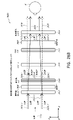
図2は、ウェアラブルディスプレイシステム80の実施例を図示する。ディスプレイシステム80は、ディスプレイ62と、ディスプレイ62の機能をサポートするための種々の機械的および電子的モジュールおよびシステムとを含む。ディスプレイ62は、フレーム64に結合されてもよく、これは、ディスプレイシステムユーザまたは視認者60によって装着可能であって、ディスプレイ62をユーザ60の眼の正面に位置付けるように構成される。ディスプレイ62は、いくつかの実施形態では、アイウェアと見なされ得る。いくつかの実施形態では、スピーカ66が、フレーム64に結合され、ユーザ60の外耳道に隣接して位置付けられる(いくつかの実施形態では、示されない別のスピーカが、ユーザの他方の外耳道に隣接して位置付けられ、ステレオ/調節可能音制御を提供する)。いくつかの実施形態では、ディスプレイシステムはまた、1つ以上のマイクロホン67または他のデバイスを含み、音を検出してもよい。いくつかの実施形態では、マイクロホンは、ユーザが、入力またはコマンド(例えば、音声メニューコマンドの選択、自然言語質問等)をシステム80に提供することを可能にするように構成され、および/または他の人物(例えば、類似ディスプレイシステムの他のユーザ)とのオーディオ通信を可能にしてもよい。マイクロホンはさらに、周辺センサとして構成され、オーディオデータを持続的に収集してもよい(例えば、ユーザおよび/または環境から受動的に収集するため)。そのようなオーディオデータは、荒い息づかい等のユーザ音または近傍イベントを示す大騒動等の環境音を含んでもよい。ディスプレイシステムはまた、周辺センサ30aを含んでもよく、これは、フレーム64と別個であって、ユーザ60の身体(例えば、ユーザ60の頭部、胴体、四肢等上)に取り付けられてもよい。周辺センサ30aは、本明細書にさらに説明されるように、いくつかの実施形態では、ユーザ60の生理学的状態を特性評価するデータを入手するように構成されてもよい。例えば、センサ30aは、電極であってもよい。
FIG. 2 illustrates an example of a
図2を継続して参照すると、ディスプレイ62は、有線導線または無線コネクティビティ等の通信リンク68によって、ローカルデータ処理モジュール70に動作可能に結合され、これは、フレーム64に固定して取り付けられる、ユーザによって装着されるヘルメットまたは帽子に固定して取り付けられる、ヘッドホンに内蔵される、または別様にユーザ60に除去可能に取り付けられる(例えば、リュック式構成において、ベルト結合式構成において)等、種々の構成において搭載されてもよい。同様に、センサ30aは、通信リンク30b、例えば、有線導線または無線コネクティビティによって、ローカルプロセッサおよびデータモジュール70に動作可能に結合されてもよい。ローカル処理およびデータモジュール70は、ハードウェアプロセッサおよび不揮発性メモリ(例えば、フラッシュメモリまたはハードディスクドライブ)等のデジタルメモリとを備えてもよく、その両方とも、データの処理、キャッシュ、および記憶を補助するために利用され得る。データは、a)画像捕捉デバイス(カメラ等)、マイクロホン、慣性測定ユニット、加速度計、コンパス、GPSユニット、無線デバイス、ジャイロスコープ、および/または本明細書に開示される他のセンサ等のセンサ(例えば、フレーム64に動作可能に結合される、または別様にユーザ60に取り付けられてもよい)から捕捉され、および/またはb)場合によっては、処理または読出後にディスプレイ62の通過のために、遠隔処理モジュール72および/または遠隔データリポジトリ74(仮想コンテンツに関連するデータを含む)を使用して入手および/または処理される、データを含む。ローカル処理およびデータモジュール70は、これらの遠隔モジュール72、74が、相互に動作可能に結合され、ローカル処理およびデータモジュール70へのリソースとして利用可能であるように、有線または無線通信リンク等を介して、通信リンク76、78によって、遠隔処理モジュール72および遠隔データリポジトリ74に動作可能に結合されてもよい。いくつかの実施形態では、ローカル処理およびデータモジュール70は、画像捕捉デバイス、マイクロホン、慣性測定ユニット、加速度計、コンパス、GPSユニット、無線デバイス、および/またはジャイロスコープ等のうちの1つ以上のものを含んでもよい。いくつかの他の実施形態では、これらのセンサのうちの1つ以上のものは、フレーム64に取り付けられてもよい、または有線または無線通信経路によってローカル処理およびデータモジュール70と通信する、独立型構造であってもよい。
With continued reference to FIG. 2, the
図2を継続して参照すると、いくつかの実施形態では、遠隔処理モジュール72は、データおよび/または画像情報を分析および処理するように構成される、1つ以上のプロセッサを備えてもよい。いくつかの実施形態では、遠隔データリポジトリ74は、デジタルデータ記憶設備を備え得、これは、インターネットまたは「クラウド」リソース構成における他のネットワーキング構成を通して利用可能であってもよい。いくつかの実施形態では、遠隔データリポジトリ74は、1つ以上の遠隔サーバを含んでもよく、これは、情報、例えば、拡張現実コンテンツを生成するための情報をローカル処理およびデータモジュール70および/または遠隔処理モジュール72に提供する。いくつかの実施形態では、全てのデータが、記憶され、全ての算出が、ローカル処理およびデータモジュールにおいて実施され、遠隔モジュールからの完全に自律的な使用を可能にする。
With continued reference to FIG. 2, in some embodiments,
「3次元」または「3-D」であるような画像の知覚は、画像の若干異なる提示を視認者の各眼に提供することによって達成されてもよい。図3は、ユーザのための3次元画像をシミュレートするための従来のディスプレイシステムを図示する。眼4、6毎に1つの2つの明確に異なる画像5、7が、ユーザに出力される。画像5、7は、視認者の視線と平行な光学またはz-軸に沿って、距離10だけ眼4、6から離間される。画像5、7は、平坦であって、眼4、6は、単一遠近調節状態をとることによって、画像に合焦させ得る。そのようなシステムは、ヒト視覚系が、画像5、7を組み合わせ、組み合わせられた画像のための深度および/またはスケールの知覚を提供することに依拠する。
Perception of an image as being "three-dimensional" or "3-D" may be achieved by providing each eye of the viewer with a slightly different presentation of the image. FIG. 3 illustrates a conventional display system for simulating a 3D image for a user. Two
しかしながら、ヒト視覚系は、より複雑であって、深度の現実的知覚を提供することは、より困難であることを理解されるであろう。例えば、従来の「3-D」ディスプレイシステムの多くの視認者は、そのようなシステムを不快であると見出す、または深度の感覚を全く知覚しない場合がある。理論によって限定されるわけではないが、オブジェクトの視認者は、輻輳・開散(vergence)と遠近調節(accmmodation)の組み合わせに起因して、オブジェクトを「3次元」として知覚し得ると考えられる。相互に対する2つの眼の輻輳・開散運動(すなわち、瞳孔が、相互に向かって、またはそこから離れるように移動し、眼の視線を収束させ、オブジェクトを固視するような眼の回転)は、眼のレンズおよび瞳孔の合焦(または「遠近調節」)と緊密に関連付けられる。通常条件下、焦点を1つのオブジェクトから異なる距離における別のオブジェクトに変化させるための眼のレンズの焦点の変化または眼の遠近調節は、「遠近調節-輻輳・開散運動反射」および散瞳または縮瞳として知られる関係下、輻輳・開散運動の整合変化を自動的に同一距離に生じさせるであろう。同様に、輻輳・開散運動の変化は、通常条件下、レンズ形状および瞳孔サイズの遠近調節の整合変化を誘起するであろう。本明細書に記載されるように、多くの立体視、すなわち、「3-D」ディスプレイシステムは、3次元視点がヒト視覚系によって知覚されるように、若干異なる提示(したがって、若干異なる画像)を使用して、場面を各眼に表示する。しかしながら、そのようなシステムは、それらが、とりわけ、単に、場面の異なる提示を提供するが、眼が全ての画像情報を単一遠近調節状態で視認する状態では、「遠近調節-輻輳・開散運動反射」に反発するため、多くの視認者にとって不快である。遠近調節と輻輳・開散運動との間のより良好な整合を提供するディスプレイシステムは、3次元画像のより現実的かつ快適なシミュレーションを形成し、増加された持続時間の装着、ひいては、診断および療法プロトコルへのコンプライアンスに寄与し得る。 However, it will be appreciated that the human visual system is more complex and providing a realistic perception of depth is more difficult. For example, many viewers of conventional "3-D" display systems may find such systems uncomfortable or may not perceive depth perception at all. Without being limited by theory, it is believed that a viewer of an object may perceive the object as "three dimensional" due to a combination of vergence and accommodation. The convergence-divergence movement of the two eyes relative to each other (i.e., the rotation of the eyes such that the pupils move toward or away from each other, converge the eye's line of sight, and fixate on an object) , is closely related to the focusing (or “accommodation”) of the eye lens and pupil. Changes in the focus of the lens of the eye or accommodation of the eye to change the focus from one object to another at different distances under normal conditions are referred to as the "accommodation-convergence-divergence kinetic reflex" and mydriasis or Under a relationship known as miosis, it will automatically produce matching changes in convergence-divergence movements at the same distance. Similarly, changes in convergence-divergence motion will induce matching changes in accommodation of lens shape and pupil size under normal conditions. As described herein, many stereoscopic, or "3-D" display systems provide slightly different presentations (and thus slightly different images) such that the three-dimensional viewpoint is perceived by the human visual system. to display the scene to each eye. However, such systems, among other things, simply provide a different presentation of the scene, while the eye sees all image information in a single accommodation state. It is uncomfortable for many viewers because it repels the 'motor reflex'. A display system that provides a better match between accommodation and convergence-divergence movements would produce a more realistic and comfortable simulation of three-dimensional images and be worn for increased duration, thus leading to diagnostic and May contribute to compliance with therapy protocols.
図4は、複数の深度平面を使用して3次元画像をシミュレートするためのアプローチの側面を図示する。図4を参照すると、z-軸上の眼4、6から種々の距離におけるオブジェクトは、それらのオブジェクトが合焦するように、眼4、6によって遠近調節される。眼(4および6)は、特定の遠近調節された状態をとり、オブジェクトをz-軸に沿った異なる距離に合焦させる。その結果、特定の遠近調節された状態は、特定の深度平面におけるオブジェクトまたはオブジェクトの一部が、眼がその深度平面に対して遠近調節された状態にあるとき、合焦するように、関連付けられた焦点距離を有する、深度平面14の特定のうちの1つと関連付けられると言え得る。いくつかの実施形態では、3次元画像は、眼4、6毎に、画像の異なる提示を提供することによって、また、深度平面のそれぞれに対応する画像の異なる提示を提供することによって、シミュレートされてもよい。例証を明確にするために、別個であるように示されるが、眼4、6の視野は、例えば、z-軸に沿った距離が増加するにつれて、重複し得ることを理解されたい。加えて、例証を容易にするために、平坦であるように示されるが、深度平面の輪郭は、深度平面内の全ての特徴が特定の遠近調節された状態における眼と合焦するように、物理的空間内で湾曲されてもよいことを理解されるであろう。
FIG. 4 illustrates aspects of an approach for simulating a three-dimensional image using multiple depth planes. Referring to FIG. 4, objects at various distances from the
オブジェクトと眼4または6との間の距離もまた、その眼によって視認されるように、オブジェクトからの光の発射量を変化させ得る。図5A-5Cは、距離と光線の発散との間の関係を図示する。オブジェクトと眼4との間の距離は、減少距離R1、R2、およびR3の順序で表される。図5A-5Cに示されるように、光線は、オブジェクトまでの距離が減少するにつれてより発散する。距離が増加するにつれて、光線は、よりコリメートされる。換言すると、点(オブジェクトまたはオブジェクトの一部)によって生成されるライトフィールドは、点がユーザの眼から離れている距離の関数である、球状波面曲率を有すると言え得る。曲率が増加すると、オブジェクトと眼4の間の距離が減少する。その結果、異なる深度平面では、光線の発散の程度もまたは、異なり、発散の程度は、深度平面と視認者の眼4との間の距離の減少に伴って増加する。単眼4のみが、図5A-5Cおよび本明細書における他の図では、例証を明確にするために図示されるが、眼4に関する議論は、視認者の両眼4および6に適用され得ることを理解されるであろう。
The distance between the object and the
理論によって限定されるわけではないが、ヒトの眼は、典型的には、有限数の深度平面を解釈し、深度知覚を提供することができると考えられる。その結果、知覚された深度の高度に真実味のあるシミュレーションが、眼にこれらの限定数の深度平面のそれぞれに対応する画像の異なる提示を提供することによって達成され得る。異なる提示は、視認者の眼によって別個に合焦され、それによって、異なる深度平面上に位置する場面のための異なる画像特徴に合焦させるために要求される眼の遠近調節に基づいて、および/または焦点外にある異なる深度平面上の異なる画像特徴の観察に基づいて、ユーザに深度キューを提供することに役立ち得る。 Without being limited by theory, it is believed that the human eye can typically interpret a finite number of depth planes to provide depth perception. As a result, a highly believable simulation of perceived depth can be achieved by presenting the eye with different presentations of images corresponding to each of these limited number of depth planes. Different presentations are focused differently by the viewer's eye, and are based on the accommodation required to focus different image features for scenes located on different depth planes; and /or It may help to provide depth cues to the user based on observation of different image features on different out-of-focus depth planes.
図6は、画像情報をユーザに出力するための導波管スタックの実施例を図示する。ディスプレイシステム1000は、複数の導波管1182、1184、1186、1188、1190を使用して3次元知覚を眼/脳に提供するために利用され得る、導波管のスタックまたはスタックされた導波管アセンブリ1178を含む。いくつかの実施形態では、ディスプレイシステム1000は、図2のシステム80であって、図6は、そのシステム80のいくつかの部分をより詳細に図式的に示す。例えば、導波管アセンブリ1178は、図2のディスプレイ62の一部であってもよい。ディスプレイシステム1000は、いくつかの実施形態では、ライトフィールドディスプレイと見なされ得ることを理解されるであろう。
FIG. 6 illustrates an example waveguide stack for outputting image information to a user. The
図6を継続して参照すると、導波管アセンブリ1178はまた、複数の特徴1198、1196、1194、1192を導波管間に含んでもよい。いくつかの実施形態では、特徴1198、1196、1194、1192は、1つ以上のレンズであってもよい。導波管1182、1184、1186、1188、1190および/または複数のレンズ1198、1196、1194、1192は、種々のレベルの波面曲率または光線発散を用いて画像情報を眼に送信するように構成されてもよい。各導波管レベルは、特定の深度平面と関連付けられてもよく、その深度平面に対応する画像情報を出力するように構成されてもよい。画像投入デバイス1200、1202、1204、1206、1208は、導波管のための光源として機能してもよく、画像情報を導波管1182、1184、1186、1188、1190の中に投入するために利用されてもよく、それぞれ、本明細書に説明されるように、眼4に向かって出力のために各個別の導波管を横断して入射光を分散させるように構成されてもよい。光は、画像投入デバイス1200、1202、1204、1206、1208の出力表面1300、1302、1304、1306、1308から出射し、導波管1182、1184、1186、1188、1190の対応する入力表面1382、1384、1386、1388、1390の中に投入される。いくつかの実施形態では、入力表面1382、1384、1386、1388、1390はそれぞれ、対応する導波管の縁であってもよい、または対応する導波管の主要表面の一部(すなわち、世界1144または視認者の眼4に直接面する導波管表面のうちの1つ)であってもよい。いくつかの実施形態では、光の単一ビーム(例えば、コリメートされたビーム)が、各導波管の中に投入され、クローン化されたコリメートビームの全体場を出力してもよく、これは、特定の導波管と関連付けられた深度平面に対応する特定の角度(および発散量)において眼4に向かって指向される。いくつかの実施形態では、画像投入デバイス1200、1202、1204、1206、1208のうちの単一の1つは、複数(例えば、3つ)の導波管1182、1184、1186、1188、1190と関連付けられ、その中に光を投入してもよい。
With continued reference to FIG. 6,
いくつかの実施形態では、画像投入デバイス1200、1202、1204、1206、1208はそれぞれ、それぞれ対応する導波管1182、1184、1186、1188、1190の中への投入のための画像情報を生成する、離散ディスプレイである。いくつかの他の実施形態では、画像投入デバイス1200、1202、1204、1206、1208は、例えば、画像情報を1つ以上の光学導管(光ファイバケーブル等)を介して、画像投入デバイス1200、1202、1204、1206、1208のそれぞれに送り得る、単一の多重化されたディスプレイの出力端である。画像投入デバイス1200、1202、1204、1206、1208によって提供される画像情報は、異なる波長または色(例えば、本明細書に議論されるように、異なる原色)の光を含んでもよいことを理解されたい。
In some embodiments,
いくつかの実施形態では、導波管1182、1184、1186、1188、1190の中に投入される光は、光プロジェクタシステム2000によって提供され、これは、光モジュール2040を備え、これは、発光ダイオード(LED)等の光エミッタを含んでもよい。光モジュール2040からの光は、ビームスプリッタ2050を介して、光変調器2030、例えば、空間光変調器によって指向および修正されてもよい。光変調器2030は、導波管1182、1184、1186、1188、1190の中に投入される光の知覚される強度を変化させるように構成されてもよい。光変調器2030は、導波管1182、1184、1186、1188、1190の中に投入される光の知覚される強度を変化させるように構成されてもよい。空間光変調器の実施例は、シリコン上液晶(LCOS)ディスプレイを含む、液晶ディスプレイ(LCD)を含む。
In some embodiments, light injected into
いくつかの実施形態では、ディスプレイシステム1000は、光を種々のパターン(例えば、ラスタ走査、螺旋走査、リサジューパターン等)で1つ以上の導波管1182、1184、1186、1188、1190の中に、最終的には、視認者の眼4に投影するように構成される、1つ以上の走査ファイバを備える、走査ファイバディスプレイであってもよい。いくつかの実施形態では、図示される画像投入デバイス1200、1202、1204、1206、1208は、光を1つまたは複数の導波管1182、1184、1186、1188、1190の中に投入するように構成される、単一走査ファイバまたは走査ファイバの束を図式的に表し得る。いくつかの他の実施形態では、図示される画像投入デバイス1200、1202、1204、1206、1208は、複数の走査ファイバまたは走査ファイバの複数の束を図式的に表し得、それぞれ、光を導波管1182、1184、1186、1188、1190のうちの関連付けられた1つの中に投入するように構成される。1つ以上の光ファイバは、光を光モジュール2040から1つ以上の導波管1182、1184、1186、1188、1190に透過するように構成されてもよいことを理解されたい。1つ以上の介在光学構造が、走査ファイバまたは複数のファイバと、1つ以上の導波管1182、1184、1186、1188、1190との間に提供され、例えば、走査ファイバから出射する光を1つ以上の導波管1182、1184、1186、1188、1190の中に再指向してもよいことを理解されたい。
In some embodiments,
コントローラ1210は、画像投入デバイス1200、1202、1204、1206、1208、光源2040、および光変調器2030の動作を含む、スタックされた導波管アセンブリ1178のうちの1つ以上のものの動作を制御する。いくつかの実施形態では、コントローラ1210は、ローカルデータ処理モジュール70の一部である。コントローラ1210は、例えば、本明細書に開示される種々のスキームのいずれかに従って、導波管1182、1184、1186、1188、1190への画像情報のタイミングおよび提供を調整する、プログラミング(例えば、非一過性媒体内の命令)を含む。いくつかの実施形態では、コントローラは、単一一体型デバイスまたは有線または無線通信チャネルによって接続される分散型システムであってもよい。コントローラ1210は、いくつかの実施形態では、処理モジュール70または72(図1)の一部であってもよい。
図6を継続して参照すると、導波管1182、1184、1186、1188、1190は、全内部反射(TIR)によって各個別の導波管内で光を伝搬するように構成されてもよい。導波管1182、1184、1186、1188、1190はそれぞれ、主要な上部および底部表面およびそれらの主要上部表面と底部表面との間に延在する縁を伴う、平面である、または別の形状(例えば、湾曲)を有してもよい。図示される構成では、導波管1182、1184、1186、1188、1190はそれぞれ、各個別の導波管内で伝搬する光を導波管から再指向し、画像情報を眼4に出力することによって、光を導波管から抽出するように構成される、外部結合光学要素1282、1284、1286、1288、1290を含んでもよい。抽出された光はまた、外部結合光と称され得、外部結合光学要素光はまた、光抽出光学要素と称され得る。抽出された光のビームは、導波管によって、導波管内で伝搬する光が光抽出光学要素に衝打する場所において出力される。外部結合光学要素1282、1284、1286、1288、1290は、例えば、本明細書にさらに議論されるような回折光学特徴を含む、格子であってもよい。説明の容易性および図面の明確性のために、導波管1182、1184、1186、1188、1190の底部主要表面に配置されて図示されるが、いくつかの実施形態では、外部結合光学要素1282、1284、1286、1288、1290は、本明細書にさらに議論されるように、上部および/または底部主要表面に配置されてもよく、および/または導波管1182、1184、1186、1188、1190の容積内に直接配置されてもよい。いくつかの実施形態では、外部結合光学要素1282、1284、1286、1288、1290は、透明基板に取り付けられ、導波管1182、1184、1186、1188、1190を形成する、材料の層内に形成されてもよい。いくつかの他の実施形態では、導波管1182、1184、1186、1188、1190は、モノリシック材料部品であってもよく、外部結合光学要素1282、1284、1286、1288、1290は、その材料部品の表面上および/または内部に形成されてもよい。
With continued reference to FIG. 6,
図6を継続して参照すると、本明細書に議論されるように、各導波管1182、1184、1186、1188、1190は、光を出力し、特定の深度平面に対応する画像を形成するように構成される。例えば、眼の最近傍の導波管1182は、眼4にコリメートされた光(そのような導波管1182の中に投入された)を送達するように構成されてもよい。コリメートされた光は、光学無限遠焦点面を表し得る。次の上方の導波管1184は、眼4に到達し得る前に、第1のレンズ1192(例えば、負のレンズ)を通して通過する、コリメートされた光を送出するように構成されてもよい。そのような第1のレンズ1192は、眼/脳が、その次の上方の導波管1184から生じる光を光学無限遠から眼4に向かって内向きにより近い第1の焦点面から生じるように解釈するように、若干の凸面波面曲率を生成するように構成されてもよい。同様に、第3の上方の導波管1186は、眼4に到達する前に、その出力光を第1の1192および第2の1194レンズの両方を通して通過させる。第1の1192および第2の1194レンズの組み合わせられた屈折力は、眼/脳が、第3の上方の導波管1186から生じる光が次の導波管1184からの光であった光学無限遠から人物に向かって内向きにさらに近い第2の焦点面から生じるように解釈するように、別の漸増量の波面曲率を生成するように構成されてもよい。
With continued reference to FIG. 6, each
他の導波管層1188、1190およびレンズ1196、1198も同様に構成され、スタック内の最高導波管1190は、人物に最も近い焦点面を表す集約焦点力のために、その出力をそれと眼との間のレンズの全てを通して送出する。スタックされた導波管アセンブリ1178の他側の世界1144から生じる光を視認/解釈するとき、レンズ1198、1196、1194、1192のスタックを補償するために、補償レンズ層1180が、スタックの上部に配置され、下方のレンズスタック1198、1196、1194、1192の集約力を補償してもよい。そのような構成は、利用可能な導波管/レンズ対と同じ数の知覚される焦点面を提供する。導波管の外部結合光学要素およびレンズの集束側面は両方とも、静的であってもよい(すなわち、動的または電気活性ではない)。いくつかの代替実施形態では、一方または両方とも、電気活性特徴を使用して動的であってもよい。
The
いくつかの実施形態では、導波管1182、1184、1186、1188、1190のうちの2つ以上のものは、同一の関連付けられた深度平面を有してもよい。例えば、複数の導波管1182、1184、1186、1188、1190が、同一深度平面に設定される画像を出力するように構成されてもよい、または導波管1182、1184、1186、1188、1190の複数のサブセットが、深度平面毎に1つのセットを伴う、同一の複数の深度平面に設定される画像を出力するように構成されてもよい。これは、それらの深度平面において拡張された視野を提供するようにタイル化された画像を形成する利点を提供し得る。
In some embodiments, two or more of
図6を継続して参照すると、外部結合光学要素1282、1284、1286、1288、1290は、導波管と関連付けられた特定の深度平面のために、光をその個別の導波管から再指向し、かつ本光を適切な量の発散またはコリメーションを伴って出力するように構成されてもよい。その結果、異なる関連付けられた深度平面を有する導波管は、外部結合光学要素1282、1284、1286、1288、1290の異なる構成を有してもよく、これは、関連付けられた深度平面に応じて、異なる量の発散を伴う光を出力する。いくつかの実施形態では、光抽出光学要素1282、1284、1286、1288、1290は、体積または表面特徴であってもよく、これは、具体的角度で光を出力するように構成されてもよい。例えば、光抽出光学要素1282、1284、1286、1288、1290は、体積ホログラム、表面ホログラム、および/または回折格子であってもよい。いくつかの実施形態では、特徴1198、1196、1194、1192は、レンズではなくてもよい。むしろ、それらは、単に、スペーサであってもよい(例えば、クラッディング層および/または空隙を形成するための構造)。
With continued reference to FIG. 6, out-coupling
いくつかの実施形態では、外部結合光学要素1282、1284、1286、1288、1290は、回折パターンまたは「回折光学要素」(また、本明細書では、「DOE」とも称される)を形成する、回折特徴である。好ましくは、DOEは、ビームの光の一部のみがDOEの各交差点を用いて眼4に向かって偏向される一方、残りが、全内部反射を介して、導波管を通して移動し続けるように、十分に低回折効率(回折されるビーム強度と入射ビーム強度の比率)を有する。画像情報を搬送する光は、したがって、様々な場所において導波管から出射する、いくつかの関連出射ビームに分割され、その結果、導波管内でバウンスする本特定のコリメートされたビームに関して、眼4に向かって非常に均一なパターンの出射放出となる。
In some embodiments, the out-coupling
いくつかの実施形態では、1つ以上のDOEは、能動的に回折する「オン」状態と有意に回折しない「オフ」状態との間で切替可能であってもよい。例えば、切替可能なDOEは、ポリマー分散液晶の層を備えてもよく、その中で微小液滴は、ホスト媒体中に回折パターンを備え、微小液滴の屈折率は、ホスト材料の屈折率に実質的に整合するように切り替えられてもよい(その場合、パターンは、入射光を著しく回折させない)、または微小液滴は、ホスト媒体のものに整合しない屈折率に切り替えられてもよい(その場合、パターンは、入射光を能動的に回折させる)。 In some embodiments, one or more of the DOEs may be switchable between an actively diffracting "on" state and a non-significantly diffracting "off" state. For example, a switchable DOE may comprise a layer of polymer-dispersed liquid crystal in which the microdroplets comprise a diffraction pattern in the host medium, and the refractive index of the microdroplets matches the refractive index of the host material. It may be switched to substantially match (in which case the pattern does not significantly diffract the incident light) or the microdroplet may be switched to a refractive index that does not match that of the host medium (its pattern actively diffracts incident light).
いくつかの実施形態では、カメラアセンブリ500(例えば、可視光および赤外線光カメラを含む、デジタルカメラ)が、提供され、眼4および/または眼4の周囲の組織の画像を捕捉し、例えば、ユーザ入力を検出し、および/またはユーザの生理学的状態を監視してもよい。本明細書で使用されるように、カメラは、任意の画像捕捉デバイスであってもよい。いくつかの実施形態では、カメラアセンブリ500は、画像捕捉デバイスと、光(例えば、赤外線光)を眼に投影し、次いで、眼によって反射され、画像捕捉デバイスによって検出され得る、光源とを含んでもよい。いくつかの実施形態では、カメラアセンブ500は、フレーム64(図2)に取り付けられてもよく、カメラアセンブリ500からの画像情報を処理し、例えば、本明細書に議論されるように、ユーザの生理学的状態に関する種々の決定を行い得る、処理モジュール70および/または72と電気通信してもよい。ユーザの生理学的状態に関する情報は、ユーザの挙動または感情状態を決定するために使用されてもよいことを理解されたい。そのような情報の実施例は、ユーザの移動および/またはユーザの顔の表情を含む。ユーザの挙動または感情状態は、次いで、挙動または感情状態、生理学的状態、および環境または仮想コンテンツデータ間の関係を決定するように、収集された環境および/または仮想コンテンツデータで三角測量されてもよい。いくつかの実施形態では、1つのカメラアセンブリ500が、眼毎に利用され、各眼を別個に監視してもよい。
In some embodiments, a camera assembly 500 (eg, a digital camera, including visible light and infrared light cameras) is provided to capture images of the
ここで図7を参照すると、導波管によって出力された出射ビームの実施例が、示される。1つの導波管が図示されるが、導波管アセンブリ1178(図6)内の他の導波管も同様に機能し得、導波管アセンブリ1178は、複数の導波管を含むことを理解されたい。光400が、導波管1182の入力表面1382において導波管1182の中に投入され、TIRによって導波管1182内を伝搬する。光400がDOE1282上に衝突する点では、光の一部は、導波管から出射ビーム402として出射する。出射ビーム402は、略平行として図示されるが、本明細書に議論されるように、また、導波管1182と関連付けられた深度平面に応じて、ある角度(例えば、発散出射ビーム形成)において眼4に伝搬するように再指向されてもよい。略平行出射ビームは、眼4からの遠距離(例えば、光学無限遠)における深度平面に設定されるように現れる画像を形成するように光を外部結合する、外部結合光学要素を伴う導波管を示し得ることを理解されたい。他の導波管または他の外部結合光学要素のセットは、より発散する、出射ビームパターンを出力してもよく、これは、眼4がより近い距離に遠近調節し、網膜に合焦させることを要求し、光学無限遠より眼4に近い距離からの光として脳によって解釈されるであろう。
Referring now to FIG. 7, an example of an output beam output by a waveguide is shown. Although one waveguide is shown, other waveguides in waveguide assembly 1178 (FIG. 6) may function similarly, and
いくつかの実施形態では、フルカラー画像が、原色、例えば、3つ以上の原色のそれぞれに画像をオーバーレイすることによって、各深度平面において形成されてもよい。図8は、スタックされた導波管アセンブリの実施例を図示し、各深度平面は、複数の異なる原色を使用して形成される画像を含む。図示される実施形態は、深度平面14a-14fを示すが、より多いまたはより少ない深度もまた、検討される。各深度平面は、第1の色Gの第1の画像、第2の色Rの第2の画像、および第3の色Bの第3の画像と関連付けられた3つ以上の原色画像を有してもよい。異なる深度平面は、文字G、R、およびBに続くジオプタ(dpt)に関する異なる数字によって図に示される。単なる実施例として、これらの文字のそれぞれに続く数字は、ジオプタ(1/m)、すなわち、視認者からの深度平面の逆距離を示し、図中の各ボックスは、個々の原色画像を表す。いくつかの実施形態では、異なる波長の光の眼の集束における差異を考慮するために、異なる原色に関する深度平面の正確な場所は、変動してもよい。例えば、所与の深度平面に関する異なる原色画像は、ユーザからの異なる距離に対応する深度平面上に設置されてもよい。そのような配列は、視力およびユーザ快適性を増加させ得、および/または色収差を減少させ得る。
In some embodiments, a full-color image may be formed in each depth plane by overlaying an image on each of the primary colors, eg, three or more primary colors. FIG. 8 illustrates an example of a stacked waveguide assembly, with each depth plane containing images formed using multiple different primary colors. Although the illustrated embodiment shows
いくつかの実施形態では、各原色の光は、単一専用導波管によって出力されてもよく、その結果、各深度平面は、それと関連付けられた複数の導波管を有してもよい。そのような実施形態では、文字G、R、またはBを含む、図中の各ボックスは、個々の導波管を表すものと理解され得、3つの導波管は、深度平面毎に提供されてもよく、3つの原色画像が、深度平面毎に提供される。各深度平面と関連付けられた導波管は、本図面では、説明を容易にするために相互に隣接して示されるが、物理的デバイスでは、導波管は全て、レベル毎に1つの導波管を伴うスタックで配列されてもよいことを理解されたい。いくつかの他の実施形態では、複数の原色が、例えば、単一導波管のみが深度平面毎に提供され得るように、同一導波管によって出力されてもよい。 In some embodiments, each primary color of light may be output by a single dedicated waveguide, such that each depth plane may have multiple waveguides associated with it. In such embodiments, each box in the figure containing the letter G, R, or B can be understood to represent an individual waveguide, three waveguides being provided per depth plane. Alternatively, three primary color images are provided per depth plane. The waveguides associated with each depth plane are shown adjacent to each other in this figure for ease of illustration, but in a physical device the waveguides would all be one waveguide per level. It should be understood that they may be arranged in stacks with tubes. In some other embodiments, multiple primary colors may be output by the same waveguide, such that for example only a single waveguide may be provided per depth plane.
図8を継続して参照すると、いくつかの実施形態では、Gは、緑色であって、Rは、赤色であって、Bは、青色である。いくつかの他の実施形態では、マゼンタ色およびシアン色を含む、光の他の波長と関連付けられた他の色も、赤色、緑色、または青色のうちの1つ以上のものに加えて使用されてもよい、またはそれらに取って代わってもよい。いくつかの実施形態では、特徴198、196、194、および192は、視認者の眼への周囲環境からの光を選択的に遮断するように構成される、能動または受動光学フィルタであってもよい。 With continued reference to FIG. 8, in some embodiments, G is green, R is red, and B is blue. In some other embodiments, other colors associated with other wavelengths of light, including magenta and cyan, are also used in addition to one or more of red, green, or blue. may replace or replace them. In some embodiments, features 198, 196, 194, and 192 may be active or passive optical filters configured to selectively block light from the surrounding environment to the viewer's eyes. good.
本開示全体を通した所与の光の色の言及は、視認者によってその所与の色であるように知覚される、光の波長の範囲内の1つ以上の波長の光を包含するものと理解されるであろうことを認識されたい。例えば、赤色光は、約620~780nmの範囲内の1つ以上の波長の光を含んでもよく、緑色光は、約492~577nmの範囲内の1つ以上の波長の光を含んでもよく、青色光は、約435~493nmの範囲内の1つ以上の波長の光を含んでもよい。 References to a given color of light throughout this disclosure encompass one or more wavelengths of light within the range of wavelengths of light perceived to be that given color by a viewer. It should be recognized that it will be understood that For example, red light may include light of one or more wavelengths within the range of about 620-780 nm, green light may include light of one or more wavelengths within the range of about 492-577 nm, Blue light may include light of one or more wavelengths within the range of approximately 435-493 nm.
いくつかの実施形態では、光源2040(図6)は、視認者の視覚的知覚範囲外の1つ以上の波長、例えば、赤外線および/または紫外線波長の光を放出するように構成されてもよい。加えて、ディスプレイ1000の導波管の内部結合、外部結合、および他の光再指向構造は、例えば、結像および/またはユーザ刺激用途のために、本光をディスプレイからユーザの眼4に向かって指向および放出するように構成されてもよい
In some embodiments, the light source 2040 (FIG. 6) may be configured to emit light at one or more wavelengths outside the visual perception range of the viewer, e.g., infrared and/or ultraviolet wavelengths. . Additionally, waveguide incoupling, outcoupling, and other light redirecting structures of the
ここで図9Aを参照すると、いくつかの実施形態では、導波管に衝突する光は、その光を導波管の中に内部結合するために再指向される必要があり得る。内部結合光学要素が、光をその対応する導波管の中に再指向および内部結合するために使用されてもよい。図9Aは、それぞれ、内部結合光学要素を含む、複数またはセット1200のスタックされた導波管の実施例の断面側面図を図示する。導波管はそれぞれ、1つ以上の異なる波長または1つ以上の異なる波長範囲の光を出力するように構成されてもよい。スタック1200は、スタック1178(図6)に対応してもよく、スタック1200の図示される導波管は、複数の導波管1182、1184、1186、1188、1190の一部に対応してもよいが、画像投入デバイス1200、1202、1204、1206、1208のうちの1つ以上のものからの光が、光が内部結合のために再指向されることを要求する位置から導波管の中に投入されることを理解されたい。
Referring now to FIG. 9A, in some embodiments, light impinging on the waveguide may need to be redirected to incoupling the light into the waveguide. An in-coupling optical element may be used to redirect and in-couple light into its corresponding waveguide. FIG. 9A illustrates a cross-sectional side view of an embodiment of a plurality or set 1200 of stacked waveguides, each including an incoupling optical element. Each waveguide may be configured to output light of one or more different wavelengths or one or more different wavelength ranges.
スタックされた導波管の図示されるセット1200は、導波管1210、1220、および1230を含む。各導波管は、関連付けられた内部結合光学要素(導波管上の光入力面積とも称され得る)を含み、例えば、内部結合光学要素1212は、導波管1210の主要表面(例えば、上側主要表面)上に配置され、内部結合光学要素1224は、導波管1220の主要表面(例えば、上側主要表面)上に配置され、内部結合光学要素1232は、導波管1230の主要表面(例えば、上側主要表面)上に配置される。いくつかの実施形態では、内部結合光学要素1212、1222、1232のうちの1つ以上のものは、個別の導波管1210、1220、1230の底部主要表面上に配置されてもよい(特に、1つ以上の内部結合光学要素は、反射性偏向光学要素である)。図示されるように、内部結合光学要素1212、1222、1232は、その個別の導波管1210、1220、1230の上側主要表面(または次の下側導波管の上部)上に配置されてもよく、特に、それらの内部結合光学要素は、透過性偏向光学要素である。いくつかの実施形態では、内部結合光学要素1212、1222、1232は、個別の導波管1210、1220、1230の本体内に配置されてもよい。いくつかの実施形態では、本明細書に議論されるように、内部結合光学要素1212、1222、1232は、他の光の波長を透過しながら、1つ以上の光の波長を選択的に再指向するような波長選択的である。その個別の導波管1210、1220、1230の片側または角に図示されるが、内部結合光学要素1212、1222、1232は、いくつかの実施形態では、その個別の導波管1210、1220、1230の他の面積内に配置されてもよいことを理解されたい。
The illustrated set 1200 of stacked waveguides includes
図示されるように、内部結合光学要素1212、1222、1232は、相互から側方にオフセットされてもよい。いくつかの実施形態では、各内部結合光学要素は、その光が別の内部結合光学要素を通して通過せずに、光を受光するようにオフセットされてもよい。例えば、各内部結合光学要素1212、1222、1232は、図6に示されるように、光を異なる画像投入デバイス1200、1202、1204、1206、および1208から受光するように構成されてもよく、光を内部結合光学要素1212、1222、1232の他のものから実質的に受光しないように、他の内部結合光学要素1212、1222、1232から分離されてもよい(例えば、側方に離間される)。
As shown, the incoupling
各導波管はまた、関連付けられた光分散要素を含み、例えば、光分散要素1214は、導波管1210の主要表面(例えば、上部主要表面)上に配置され、光分散要素1224は、導波管1220の主要表面(例えば、上部主要表面)上に配置され、光分散要素1234は、導波管1230の主要表面(例えば、上部主要表面)上に配置される。いくつかの他の実施形態では、光分散要素1214、1224、1234は、それぞれ、関連付けられた導波管1210、1220、1230の底部主要表面上に配置されてもよい。いくつかの他の実施形態では、光分散要素1214、1224、1234は、それぞれ、関連付けられた導波管1210、1220、1230の上部および底部両方の主要表面上に配置されてもよい、または光分散要素1214、1224、1234は、それぞれ、異なる関連付けられた導波管1210、1220、1230内の上部および底部主要表面の異なるもの上に配置されてもよい。
Each waveguide also includes an associated light dispersive element, eg,
導波管1210、1220、1230は、例えば、材料のガス、液体、および/または固体層によって離間および分離されてもよい。例えば、図示されるように、層1218aは、導波管1210および1220を分離してもよく、層1218bは、導波管1220および1230を分離してもよい。いくつかの実施形態では、層1218aおよび1218bは、低屈折率材料(すなわち、導波管1210、1220、1230の直近のものを形成する材料より低い屈折率を有する材料)から形成される。好ましくは、層1218a、1218bを形成する材料の屈折率は、導波管1210、1220、1230を形成する材料の屈折率よりも0.05以上、または0.10以上小さい。有利には、より低い屈折率層1218a、1218bは、導波管1210、1220、1230を通して光の全内部反射(TIR)(例えば、各導波管の上部および底部主要表面間のTIR)を促進する、クラッディング層として機能してもよい。いくつかの実施形態では、層1218a、1218bは、空気から形成される。図示されないが、導波管の図示されるセット1200の上部および底部は、直近クラッディング層を含んでもよいことを理解されたい。
好ましくは、製造および他の考慮点を容易にするために、導波管1210、1220、1230を形成する材料は、類似または同一であって、層1218a、1218bを形成する材料は、類似または同一である。いくつかの実施形態では、導波管1210、1220、1230を形成する材料は、1つ以上の導波管間で異なってもよい、および/または層1218a、1218bを形成する材料は、依然として、前述の種々の屈折率関係を保持しながら、異なってもよい。
Preferably, for ease of manufacture and other considerations, the
図9Aを継続して参照すると、光線1240、1242、1244が、導波管のセット1200に入射する。光線1240、1242、1244は、1つ以上の画像投入デバイス1200、1202、1204、1206、1208(図6)によって導波管1210、1220、1230の中に投入されてもよいことを理解されたい。
With continued reference to FIG. 9A,
いくつかの実施形態では、光線1240、1242、1244は、異なる色に対応し得る、異なる性質、例えば、異なる波長または異なる波長範囲を有する。内部結合光学要素1212、1222、1232はそれぞれ、光がTIRによって導波管1210、122、1230のうちの個別の1つを通して伝搬するように、入射光を偏向させる。
In some embodiments,
例えば、内部結合光学要素1212は、第1の波長または波長範囲を有する、光線1240を偏向させるように構成されてもよい。同様に、透過される光線1242は、第2の波長または波長範囲の光を選択的に偏向させるように構成される、内部結合光学要素1222に衝突し、それによって偏向される。同様に、光線1244は、第3の波長または波長範囲の光を選択的に偏向させるように構成される、内部結合光学要素1232によって偏向される。
For example, incoupling
図9Aを継続して参照すると、偏向された光線1240、1242、1244は、対応する導波管1210、1220、1230を通して伝搬するように偏向される。すなわち、各導波管の内部結合光学要素1212、1222、1232は、光をその対応する導波管1210、1220、1230の中に偏向させ、光を対応する導波管の中に内部結合する。光線1240、1242、1244は、光をTIRによって個別の導波管1210、1220、1230を通して伝搬させる角度で偏向される。光線1240、1242、1244は、導波管の対応する光分散要素1214、1224、1234に衝突するまで、TIRによって個別の導波管1210、1220、1230を通して伝搬する。
With continued reference to FIG. 9A, the deflected
ここで図9Bを参照すると、図9Aの複数のスタックされた導波管の実施例の斜視図が、図示される。前述のように、内部結合された光線1240、1242、1244は、それぞれ、内部結合光学要素1212、1222、1232によって偏向され、次いで、それぞれ、導波管1210、1220、1230内でTIRによって伝搬する。光線1240、1242、1244は、次いで、それぞれ、光分散要素1214、1224、1234に衝突する。光分散要素1214、1224、1234は、それぞれ、外部結合光学要素1250、1252、1254に向かって伝搬するように、光線1240、1242、1244を偏向させる。
Referring now to FIG. 9B, a perspective view of the multiple stacked waveguide embodiment of FIG. 9A is illustrated. As previously described, incoupled
いくつかの実施形態では、光分散要素1214、1224、1234は、直交瞳エクスパンダ(OPE)である。いくつかの実施形態では、OPEは、光を外部結合光学要素1250、1252、1254に偏向または分散させることと、また、外部結合光学要素に伝搬するにつれて、本光のビームまたはスポットサイズを増加させることの両方を行う。いくつかの実施形態では、例えば、ビームサイズがすでに所望のサイズである場合、光分散要素1214、1224、1234は、省略されてもよく、内部結合光学要素1212、1222、1232は、光を直接外部結合光学要素1250、1252、1254に偏向させるように構成されてもよい。例えば、図9Aを参照すると、光分散要素1214、1224、1234は、それぞれ、外部結合光学要素1250、1252、1254と置換されてもよい。いくつかの実施形態では、外部結合光学要素1250、1252、1254は、光を視認者の眼4(図7)内に指向する、射出瞳(EP)または射出瞳エクスパンダ(EPE)である。
In some embodiments, light
故に、図9Aおよび9Bを参照すると、いくつかの実施形態では、導波管のセット1200は、原色毎に、導波管1210、1220、1230と、内部結合光学要素1212、1222、1232と、光分散要素(例えば、OPE)1214、1224、1234と、外部結合光学要素(例えば、EP)1250、1252、1254とを含む。導波管1210、1220、1230は、各1つの間に空隙/クラッディング層を伴ってスタックされてもよい。内部結合光学要素1212、1222、1232は、入射光をその導波管の中に再指向または偏向させる(異なる内部結合光学要素は、異なる波長の光を受光する)。光は、次いで、個別の導波管1210、1220、1230内でTIRをもたらすであろう、角度で伝搬する。示される実施例では、光線1240(例えば、青色光)は、先に説明された様式において、第1の内部結合光学要素1212によって偏向され、次いで、導波管を辿ってバウンスし続け、光分散要素(例えば、OPE)1214、次いで、外部結合光学要素(例えば、EP)1250と相互作用する。光線1242および1244(例えば、それぞれ、緑色および赤色光)は、導波管1210を通して通過し、光線1242は、内部結合光学要素1222に衝突し、それによって偏向されるであろう。光線1242は、次いで、TIRを介して、導波管1220を辿ってバウンスし、その光分散要素(例えば、OPE)1224、次いで、外部結合光学要素(例えば、EP)1252に進む。最後に、光線1244(例えば、赤色光)は、導波管1220を通して通過し、導波管1230の光内部結合光学要素1232に衝突する。光内部結合光学要素1232は、光線が、TIRによって、光分散要素(例えば、OPE)1234に、次いで、TIRによって、外部結合光学要素(例えば、EP)1254に伝搬するように、光線1244を偏向させる。外部結合光学要素1254は、次いで、最後に、光線1244を視認者に外部結合し、視認者はまた、他の導波管1210、1220から外部結合された光も受光する。
9A and 9B, in some embodiments, the set of
図9Cは、図9Aおよび9Bの複数のスタックされた導波管の実施例の上下平面図を図示する。図示されるように、導波管1210、1220、1230は、各導波管の関連付けられた光分散要素1214、1224、1234および関連付けられた外部結合光学要素1250、1252、1254とともに、垂直に整合されてもよい。しかしながら、本明細書に議論されるように、内部結合光学要素1212、1222、1232は、垂直に整合されない。むしろ、内部結合光学要素は、好ましくは、非重複する(例えば、上下図に見られるように、側方に離間される)。本明細書でさらに議論されるように、本非重複空間配列は、1対1ベースで異なるリソースから異なる導波管の中への光の投入を促進し、それによって、具体的光源が具体的導波管に一意に結合されることを可能にする。いくつかの実施形態では、非重複の空間的に分離される内部結合光学要素を含む、配列は、偏移瞳システムと称され得、これらの配列内の内部結合光学要素は、サブ瞳に対応し得る。
(液晶に基づくブラッグ反射構造)
FIG. 9C illustrates a top-down plan view of the multiple stacked waveguide embodiment of FIGS. 9A and 9B. As shown, the
(Bragg reflection structure based on liquid crystal)
概して、液晶は、従来の流体と固体との間の中間であり得る、物理的性質を保有する。液晶は、いくつかの側面では、流体状であるが、大部分の流体と異なり、液晶内の分子の配列は、いくつかの構造秩序を呈する。異なるタイプの液晶は、サーモトロピック、リオトロピック、およびポリマー液晶を含む。本明細書に開示されるサーモトロピック液晶は、ネマチック状態/位相、スメクチック状態/位相、キラルネマチック状態/位相、またはキラルスメクチック状態/位相を含む、種々の物理的状態、例えば、位相に実装されることができる。 Generally, liquid crystals possess physical properties that may be intermediate between those of conventional fluids and solids. Liquid crystals are in some aspects fluid-like, but unlike most fluids, the arrangement of molecules within liquid crystals exhibits some structural order. Different types of liquid crystals include thermotropic, lyotropic, and polymeric liquid crystals. The thermotropic liquid crystals disclosed herein implement various physical states, e.g., phases, including nematic states/phases, smectic states/phases, chiral nematic states/phases, or chiral smectic states/phases. be able to.
本明細書に説明されるように、ネマチック状態または位相における液晶は、比較的に少ない位置秩序を有する一方、その長軸が略平行である状態で長距離指向性秩序を有する、カラミチック(棒形状)またはディスコチック(円板形状)有機分子を有することができる。したがって、有機分子は、依然として、その長距離指向性秩序を維持しながら、その質量中心位置が液体中におけるようにランダムに分散された状態で自由に流動し得る。いくつかの実装では、ネマチック位相における液晶は、一軸性であり得る。すなわち、液晶は、より長くかつ好ましい1つの軸を有し、他の2つは、ほぼ同等である。他の実装では、液晶は、二軸性であり得る。すなわち、その長軸の配向に加え、液晶はまた、二次軸に沿って配向され得る。 As explained herein, liquid crystals in the nematic state or phase have relatively little positional order, while having long-range directional order with their long axes nearly parallel, calamitic (rod-shaped ) or discotic (disk-shaped) organic molecules. Thus, organic molecules can flow freely with their center-of-mass positions randomly distributed as in liquids, while still maintaining their long-range directional order. In some implementations, liquid crystals in nematic phase can be uniaxial. That is, liquid crystals have one axis that is longer and preferred, and the other two are approximately equivalent. In other implementations, the liquid crystal can be biaxial. That is, in addition to aligning its major axis, the liquid crystal can also be oriented along its secondary axis.
本明細書に説明されるように、スメクチック状態または位相における液晶は、相互にわたって摺動し得る比較的に明確に画定された層を形成する、有機分子を有することができる。いくつかの実装では、スメクチック位相における液晶は、1つの方向に沿って位置的に秩序付けられることができる。いくつかの実装では、分子の長軸は、液晶層の平面に対して略法線の方向に沿って配向されることができる一方、他の実装では、分子の長軸は、層の平面に対して略法線の方向に対して傾斜されてもよい。 As described herein, liquid crystals in a smectic state or phase can have organic molecules that form relatively well-defined layers that can slide across each other. In some implementations, liquid crystals in smectic phase can be positionally ordered along one direction. In some implementations, the long axes of the molecules can be oriented along directions that are approximately normal to the plane of the liquid crystal layer, while in other implementations the long axes of the molecules are aligned with the plane of the layer. It may be tilted with respect to the substantially normal direction.
本明細書では、本開示全体を通して、ネマチック液晶は、棒状分子から成り、近傍分子の長軸は、相互に近似的に整合される。本異方性構造を説明するために、配向子と呼ばれる、無次元単位ベクトルnが、液晶分子の好ましい配向の方向を説明するために使用され得る。 As used herein throughout the disclosure, nematic liquid crystals consist of rod-like molecules, with the long axes of neighboring molecules approximately aligned with each other. To describe this anisotropic structure, a dimensionless unit vector n, called the director, can be used to describe the preferred direction of alignment of the liquid crystal molecules.
本明細書では、本開示全体を通して、傾斜角度または事前傾斜角度Φは、液晶層または基板の主要表面(x-y平面)と垂直な平面、例えば、x-z平面において測定され、かつ整合方向と主要表面または主要表面と平行方向、例えば、x-方向との間で測定される、角度を指し得る。 Herein, throughout this disclosure, the tilt angle or pre-tilt angle Φ is measured in a plane perpendicular to the major surface (xy plane) of the liquid crystal layer or substrate, eg, the xz plane, and in the alignment direction may refer to an angle measured between and a major surface or a parallel direction to a major surface, eg, the x-direction.
本明細書では、本開示全体を通して、方位角または回転角度φは、層法線方向または液晶層の主要表面に対して法線の軸を中心とした回転の角度を説明するために使用され、これは、液晶層または基板の主要表面と平行な平面、例えば、x-y平面において測定され、かつ整合方向、例えば、身長方向または配向子の方向と、主要表面と平行方向、例えば、y-方向との間で測定される。 Herein, throughout this disclosure, azimuth or rotation angle φ is used to describe the angle of rotation about the layer normal direction or axis normal to the major surfaces of the liquid crystal layer, It is measured in a plane parallel to the major surfaces of the liquid crystal layer or substrate, eg, the xy plane, and is an alignment direction, eg, the height direction or director direction, and a direction parallel to the major surfaces, eg, the y-plane. Measured between directions.
本明細書では、本開示全体を通して、回転角度φまたは事前傾斜角度Φ等の整合角度が、異なる領域間で実質的に同一であると称されるとき、平均整合角度は、例えば、相互に約1%、約5%、または約10%以内であり得るが、平均整合は、ある場合には、より大きくあり得ることを理解されたい。 Throughout this disclosure, when alignment angles, such as rotation angles φ or pre-tilt angles Φ, are referred to as being substantially the same between different regions, the average alignment angles are, for example, about It should be understood that the average match can be greater in some cases, although it can be within 1%, about 5%, or about 10%.
本明細書では、本明細書全体を通して、デューティサイクルは、例えば、第1の整合方向に整合される液晶分子を有する第1の領域の第1の側方寸法と第1の領域を有するゾーンの格子周期との間の比率を指し得る。適用可能である場合、第1の領域は、液晶の整合が異なるゾーン間で変動しない、領域に対応する。 As used herein and throughout the specification, the duty cycle is, for example, the first lateral dimension of the first region having the liquid crystal molecules aligned in the first alignment direction and the width of the zone having the first region. It can refer to the ratio between the grating period. Where applicable, the first region corresponds to regions where the alignment of the liquid crystal does not vary between different zones.
本明細書に説明されるように、ネマチック状態またはスメクチック状態における液晶はまた、キラリティを呈することができる。そのような液晶は、キラル位相またはコレステリック位相にあると称される。キラルまたはコレステリック位相では、液晶は、配向子と垂直な分子の捻転を呈することができ、分子軸は、配向子と平行である。隣接する分子間の有限捻転角度は、その非対称充塞に起因し、これは、より長距離のキラル秩序をもたらす。 As described herein, liquid crystals in the nematic or smectic state can also exhibit chirality. Such liquid crystals are said to be in a chiral or cholesteric phase. In the chiral or cholesteric phase, the liquid crystal can exhibit molecular twists perpendicular to the director, with the molecular axes parallel to the director. The finite twist angle between adjacent molecules is due to their asymmetric packing, which leads to longer-range chiral order.
本明細書に説明されるように、キラルスメクチック状態または位相における液晶は、液晶分子が位置秩序を層化構造内に有するように構成されることができ、分子は、層法線に対してある有限角度によって傾斜される。加えて、キラリティは、層法線方向における1つの液晶層から次の液晶層へと層法線に対する垂直方向に対して液晶分子の連続方位角捻転を誘発し、それによって、分子軸の螺旋捻転を層法線に沿って生産することができる。 As described herein, liquid crystals in a chiral smectic state or phase can be configured such that the liquid crystal molecules have a positional order within the layered structure, the molecules lying with respect to the layer normal Tilted by a finite angle. In addition, chirality induces a continuous azimuthal twist of the liquid crystal molecules from one liquid crystal layer to the next in the layer normal direction with respect to the direction perpendicular to the layer normal, thereby causing a helical twist of the molecular axis. can be produced along the layer normal.
本明細書に説明されるように、本開示全体を通して、キラル構造は、ある方向、例えば、層深度方向等の配向子と方向垂直に延在し、ある回転方向、例えば、時計回りまたは反時計回りに連続的に回転または捻転される、コレステリック位相における複数の液晶分子を指す。一側面では、キラル構造内の液晶分子の配向子は、ある螺旋ピッチを有する螺旋として特徴付けられることができる。 As described herein, throughout the present disclosure chiral structures extend in a direction, e.g. Refers to multiple liquid crystal molecules in a cholesteric phase that are continuously rotated or twisted about. In one aspect, the director of the liquid crystal molecules in the chiral structure can be characterized as a helix with a certain helical pitch.
本明細書に説明されるように、キラリティを示すコレステリック位相における液晶は、キラルピッチまたは螺旋ピッチ(p)を有するように説明され得、これは、第1の回転方向における完全1回転によるキラル構造の液晶分子の正味回転角度に対応する、層深度方向における長さに対応する。言い換えると、螺旋ピッチは、液晶分子が完全360°捻転を受ける距離を指す。螺旋ピッチ(p)は、例えば、温度が改変されると、または他の分子が液晶ホストに添加されると(アキラル液体ホスト材料は、キラル材料でドープされる場合、キラル位相を形成し得る)、変化し、適宜、所与の材料の螺旋ピッチ(p)が調整されることを可能にし得る。いくつかの液晶システムでは、螺旋ピッチは、可視光の波長と同一秩序である。本明細書に説明されるように、キラリティを示す液晶はまた、捻転角度または回転角度(φ)を有するものとして説明され得、これは、例えば、層法線方向における連続液晶分子間の相対的方位角回転を指し得、かつ正味捻転角度または正味回転角度を有するものとして説明され得、これは、例えば、規定された長さ、例えば、キラル構造の長さまたは液晶層の厚さを横断した最上液晶分子と最下液晶分子との間の相対的方位角回転を指し得る。 As described herein, a liquid crystal in a cholesteric phase exhibiting chirality can be described as having a chiral pitch or helical pitch (p), which is the chiral structure due to one complete rotation in the first rotational direction. Corresponding to the length in the layer depth direction corresponding to the net rotation angle of the liquid crystal molecules. In other words, the helical pitch refers to the distance over which the liquid crystal molecules undergo a full 360° twist. The helical pitch (p) changes, for example, when the temperature is modified, or when other molecules are added to the liquid crystal host (achiral liquid host materials can form chiral phases when doped with chiral materials). , may vary, allowing the helical pitch (p) of a given material to be adjusted accordingly. In some liquid crystal systems, the helical pitch is co-ordered with the wavelength of visible light. As described herein, liquid crystals exhibiting chirality can also be described as having a twist or rotation angle (φ), which is, for example, the relative It can refer to azimuthal rotation and can be described as having a net twist angle or a net rotation angle, which for example traverses a defined length, such as the length of a chiral structure or the thickness of a liquid crystal layer. It can refer to the relative azimuthal rotation between the top and bottom liquid crystal molecules.
本明細書に説明される種々の実施形態によると、上記に説明されるような種々の状態または位相を有する、液晶は、例えば、複屈折、光学異方性、および薄膜プロセスを使用した製造可能性を含む、種々の望ましい材料性質をもたらすように構成されることができる。例えば、液晶層の表面条件を変化させ、および/または異なる液晶材料を混合することによって、空間可変回折性質、例えば、勾配回折効率を呈する、格子構造が、加工されることができる。 According to various embodiments described herein, liquid crystals, having various states or phases as described above, can be manufactured using, for example, birefringence, optical anisotropy, and thin film processes It can be configured to provide a variety of desired material properties, including flexibility. For example, by varying the surface conditions of the liquid crystal layer and/or mixing different liquid crystal materials, grating structures can be fabricated that exhibit spatially variable diffractive properties, eg gradient diffraction efficiencies.
本明細書に説明されるように、「重合化可能液晶」は、重合される、例えば、原位置で光重合され得、また、本明細書では、反応性メソゲン(RM)として説明され得る、液晶材料を指し得る。 As described herein, a "polymerizable liquid crystal" can be polymerized, e.g., photopolymerized in situ, and can also be described herein as a reactive mesogen (RM). It can refer to a liquid crystal material.
液晶分子は、いくつかの実施形態では、重合化可能であり得、いったん重合されると、他の液晶分子と大規模な網状体を形成し得ることを理解されたい。例えば、液晶分子は、化学結合または化学種を他の液晶分子に連結することによって、連結されてもよい。いったんともに継合されると、液晶分子は、ともに連結される前と実質的に同一配向および場所を有する、液晶ドメインを形成し得る。説明を容易にするために、用語「液晶分子」は、本明細書では、重合化前の液晶分子と、重合化後のこれらの分子によって形成される液晶ドメインの両方を指すために使用される。 It should be appreciated that the liquid crystal molecules may, in some embodiments, be polymerizable and, once polymerized, may form large networks with other liquid crystal molecules. For example, liquid crystal molecules may be linked by linking chemical bonds or chemical species to other liquid crystal molecules. Once spliced together, the liquid crystal molecules can form liquid crystal domains that have substantially the same orientation and location as before they were joined together. For ease of explanation, the term "liquid crystal molecules" is used herein to refer both to liquid crystal molecules before polymerization and to liquid crystal domains formed by these molecules after polymerization. .
本明細書に説明される特定の実施形態によると、光重合化可能液晶材料は、ブラッグ反射構造、例えば、回折格子を形成するように構成されることができ、複屈折、キラリティ、および複数のコーティングの容易性を含む、その材料性質は、異なる材料性質、例えば、複屈折、キラリティ、および厚さを伴う回折格子を作成するために利用されることができ、これは、異なる光学性質、例えば、いくつか挙げると、回折効率、波長選択性、および軸外回折角度選択性をもたらし得る。 According to certain embodiments described herein, the photopolymerizable liquid crystal material can be configured to form Bragg reflection structures, e.g., diffraction gratings, with birefringence, chirality and multiple Its material properties, including ease of coating, can be exploited to create diffraction gratings with different material properties, e.g. , can result in diffraction efficiency, wavelength selectivity, and off-axis diffraction angle selectivity, to name a few.
本明細書に説明されるように、「透過」または「透明」構造、例えば、透明基板は、入射光の少なくとも一部、例えば、少なくとも20、30、または50%が、それを通して通過することを可能にし得ることを理解されたい。故に、透明基板は、いくつかの実施形態では、ガラス、サファイア、またはポリマー基板であってもよい。対照的に、「反射」構造、例えば、反射基板は、入射光の少なくとも一部、例えば、少なくとも20、30、50、70、90%、以上のものを反射させ、そこから反射させ得る。 As described herein, a "transmissive" or "transparent" structure, e.g., a transparent substrate, allows at least a portion, e.g., at least 20, 30, or 50%, of incident light to pass through it. It should be understood that this may be possible. Thus, the transparent substrate may be glass, sapphire, or polymer substrate in some embodiments. In contrast, a "reflective" structure, eg, a reflective substrate, may reflect at least a portion, eg, at least 20, 30, 50, 70, 90%, or more, of the incident light to and from it.
格子の光学性質は、格子の物理的構造(例えば、周期性、深度、およびデューティサイクル)および格子の材料性質(例えば、屈折率、吸収率、および複屈折)によって決定される。液晶が、使用されるとき、格子の光学性質は、例えば、液晶材料の分子配向または分布を制御することによって制御されることができる。例えば、格子面積を横断して液晶材料の分子配向または分布を変動させることによって、格子は、段階的な回折効率を呈し得る。そのようなアプローチは、図を参照して以下に説明される。
(コレステリック液晶回折格子(CLCG))
The optical properties of the grating are determined by the grating's physical structure (eg, periodicity, depth, and duty cycle) and the grating's material properties (eg, refractive index, absorption, and birefringence). When liquid crystals are used, the optical properties of the grating can be controlled, for example, by controlling the molecular orientation or distribution of the liquid crystal material. For example, the grating can exhibit graded diffraction efficiency by varying the molecular orientation or distribution of the liquid crystal material across the grating area. Such an approach is described below with reference to figures.
(Cholesteric Liquid Crystal Grating (CLCG))
図6および7を参照して前述で説明されたように、本明細書に説明される種々の実施形態による、ディスプレイシステムは、光学要素、例えば、内部結合光学要素、外部結合光学要素、および光分散要素を含んでもよく、これは、回折格子を含んでもよい。例えば、図7を参照して上記に説明されるように、導波管1182の入力表面1382において導波管1182の中に投入される、光400は、全内部反射(TIR)によって、導波管1182内を伝搬する。光400が外部結合光学要素1282上に衝突する点において、光の一部は、導波管から出射ビーム402として出射する。いくつかの実装では、光学要素1182、1282、または1382のいずれかは、回折格子として構成されることができる。
As described above with reference to FIGS. 6 and 7, display systems according to various embodiments described herein include optical elements such as incoupling optical elements, outcoupling optical elements, and light A dispersive element may be included, which may include a diffraction grating. For example, as described above with reference to FIG. 7, light 400 launched into
光を導波管1182の中に効率的に内部結合させる(またはそこから外部結合させる)ことは、例えば、仮想/拡張/複合現実ディスプレイ用途のための導波管ベースのシースルーディスプレイを設計する際の課題であり得る。これらおよび他の用途に関して、その構造が回折性質を含む、種々の光学性質を最適化するように構成可能な材料から形成される回折格子を有することが望ましい。望ましい回折性質は、他の性質の中でもとりわけ、偏光選択性、スペクトル選択性、角度選択性、高スペクトル帯域幅、および高回折効率を含む。これらおよび他の必要性に対処するために、本明細書に開示される種々の実施形態では、光学要素1282は、コレステリック液晶回折格子(CLCG)として構成される。後述に説明されるように、種々の実施形態によるCLCGは、とりわけ、偏光選択性、帯域幅、位相プロファイル、回折性質の空間変動、スペクトル選択性、および高回折効率を最適化するように構成されることができる。
Efficient incoupling of light into (or out of)
以下では、種々の光学性質のために最適化されたコレステリック液晶(CLC)を備える、反射液晶回折格子として構成される、CLCGの種々の実施形態が、説明される。概して、回折格子は、周期的構造を有し、これは、光を異なる方向に進行するいくつかのビームに分裂および回折させる。これらのビームの方向は、とりわけ、周期的構造の周期および光の波長に依存する。外部結合光学要素1282(図6、7)等のある用途に関して、ある光学性質、例えば、回折効率を最適化するために、CLCの種々の材料性質は、後述に説明されるように、最適化されることができる。 In the following, various embodiments of CLCGs configured as reflective liquid crystal gratings are described, comprising cholesteric liquid crystals (CLCs) optimized for different optical properties. Generally, a diffraction grating has a periodic structure that splits and diffracts light into several beams traveling in different directions. The direction of these beams depends, among other things, on the period of the periodic structure and the wavelength of the light. For certain applications, such as the out-coupling optical element 1282 (FIGS. 6, 7), to optimize certain optical properties, e.g., diffraction efficiency, various material properties of the CLC may be optimized as described below. can be
前述で説明されるように、キラル(ネマチック)位相またはコレステリック位相位おけるコレステリック液晶(CLC)層の液晶分子は、液晶層の法線方向または深度方向における膜の位置の関数として、配向子の連続方位角捻転を有するように配列される、複数の液晶分子によって特徴付けられる。本明細書に説明されるように、連続方位角捻転を有するように配列される、液晶分子は、集合的に、本明細書では、キラル構造と称される。本明細書に説明されるように、方位角捻転または回転の角度(φ)は、前述で説明されるように、層法線と平行な方向に対する液晶分子の配向子間の角度として説明される。キラル構造の液晶分子の空間可変配向子は、螺旋パターンを形成するものとして説明され得、螺旋ピッチ(p)は、上記に説明されるように、配向子が360o回転した距離(例えば、液晶層の層法線方向)として定義される。本明細書に説明されるように、回折格子として構成されるCLC層は、液晶の分子構造が深度方向に対して法線の側方方向に周期的に反復する、側方寸法を有する。側方方向における本周期性は、格子周期(∧)と称される。 As explained above, the liquid crystal molecules of a cholesteric liquid crystal (CLC) layer in a chiral (nematic) phase or cholesteric phase are arranged in a sequence of directors as a function of film position in the normal or depth direction of the liquid crystal layer. It is characterized by a plurality of liquid crystal molecules arranged with an azimuthal twist. Liquid crystal molecules arranged to have continuous azimuthal twist, as described herein, are collectively referred to herein as chiral structures. As described herein, the angle of azimuthal twist or rotation (φ) is described as the angle between the director of the liquid crystal molecules relative to the direction parallel to the layer normal, as previously described. . A spatially variable director of liquid crystal molecules with a chiral structure can be described as forming a helical pattern, and the helical pitch (p) is the distance the director is rotated 360 ° , as described above (e.g., liquid crystal layer normal direction of the layer). As described herein, a CLC layer configured as a diffraction grating has lateral dimensions in which the molecular structure of the liquid crystal repeats periodically laterally of the normal to the depth direction. This periodicity in the lateral direction is called the grating period (∧).
本明細書に説明される種々の実施形態によると、回折格子は、複数のキラル構造を備える、コレステリック液晶(CLC)層を備え、各キラル構造は、少なくともある螺旋ピッチによって、層深度方向に延在し、第1の回転方向に連続的に回転される、複数の液晶分子を備える。螺旋ピッチは、第1の回転方向における完全1回転によるキラル構造の液晶分子の正味回転角度に対応する、層深度方向における長さである。キラル構造の液晶分子の配列は、層深度方向と垂直な側方方向に周期的に変動する。 According to various embodiments described herein, a diffraction grating comprises a cholesteric liquid crystal (CLC) layer comprising a plurality of chiral structures, each chiral structure extending in the layer depth direction by at least some helical pitch. A plurality of liquid crystal molecules are present and continuously rotated in a first rotational direction. The helical pitch is the length in the layer depth direction corresponding to the net rotation angle of the chiral structured liquid crystal molecules through one complete rotation in the first rotation direction. The alignment of the liquid crystal molecules with the chiral structure varies periodically in the lateral direction perpendicular to the layer depth direction.
図10は、複数の均一キラル構造を備える、コレステリック液晶(CLC)層1004の断面側面図を図示する。CLC1004は、複数のキラル構造1012-1、1012-2、...1012-iとして配列される、液晶分子を備える、CLC層1008を備え、各キラル構造は、複数の液晶分子を備え、iは、2を上回る任意の好適な整数である。例えば、キラル構造1012-1は、層法線方向、例えば、図示される実施形態では、z-方向に延在するように配列される、複数の液晶分子1012-1-1、1012-1-2、...1012-1-jを備え、jは、2を上回る任意の好適な整数である。各キラル構造の液晶分子は、第1の回転方向に連続的に回転される。図示される実施形態では、液晶分子は、z-軸の正の方向(すなわち、軸矢印の方向)または入射光ビーム1016-L、1016-Rの伝搬方向において見られると、時計回り方向に連続的に回転される。例えば、図示される実施形態では、キラル構造1012-1の液晶分子1012-1-1、1012-1-2、...1012-1-jは、例えば、正のx-方向に対して、回転角度φ1、φ2、...φjだけ連続的に回転される。図示される実施形態では、例証的目的のために、z-方向における対向端間のキラル構造1012-1、1012-2、...1012-iのそれぞれの複数の液晶分子は、液晶分子の正味回転角度が約360oであるように、完全1回転または旋回分、回転される。その結果、キラル構造1012-1、1012-2、...1012-iは、z-方向に、螺旋ピッチpと同一である長さLを有する。しかしながら、実施形態は、そのように限定されず、キラル構造1012-1、1012-2、...1012-iは、1回を上回るまたはそれ未満の任意の数の完全回転、360oより低いまたはより高い任意の好適な正味回転角度、および/または螺旋ピッチpより短いまたはより長いz-方向における任意の好適な長さLを有することができる。例えば、本明細書に説明される種々の実施形態では、キラル構造の完全旋回の数は、他の数の中でもとりわけ、1~3、2~4、3~5、4~6、5~7、6~8、7~9、または8~10であることができる。
FIG. 10 illustrates a cross-sectional side view of a cholesteric liquid crystal (CLC)
依然として、図10を参照すると、z-方向における隣接する液晶分子間の連続回転角度φ1、φ2、...φjは、いくつかの実施形態によると、同一である、またはいくつかの他の実施形態によると、異なることができる。例証として、図示される実施形態では、キラル構造1012-1、1012-2、...1012-iの長さは、約pであって、正味回転角度は、z-方向における隣接する液晶分子が約360o/(m-1)回転されるように、360oであって、mは、キラル構造内の液晶分子の数である。例えば、例証的目的のために、キラル構造1012-1、1012-2、...1012-iはそれぞれ、z-方向における隣接する液晶分子が相互に対して約30o回転されるように、13の液晶分子を有する。当然ながら、種々の実施形態におけるキラル構造は、任意の好適な数の液晶分子を有することができる。 Still referring to FIG. 10, the continuous rotation angles φ1, φ2, . . . φj can be the same, according to some embodiments, or different, according to some other embodiments. By way of illustration, in the illustrated embodiment, chiral structures 1012-1, 1012-2, . . . The length of 1012-i is approximately p, the net rotation angle is 360 ° such that adjacent liquid crystal molecules in the z-direction are rotated approximately 360 ° /(m−1), and m is the number of liquid crystal molecules in the chiral structure. For example, chiral structures 1012-1, 1012-2, . . . 1012-i each have 13 liquid crystal molecules such that adjacent liquid crystal molecules in the z-direction are rotated about 30 ° relative to each other. Of course, the chiral structure in various embodiments can have any suitable number of liquid crystal molecules.
したがって、依然として、図10を参照すると、側方方向、例えば、x-方向に隣接する、キラル構造は、同様に配列される液晶分子を有する。図示される実施形態では、キラル構造1012-1、1012-2、...1012-iは、ほぼ同一深度における異なるキラル構造の液晶分子、例えば、光入射表面1004Sに最も近い液晶分子が、ほぼ同一深度における同一回転角度、および連続液晶分子の連続回転角度、および各キラル構造の液晶分子の正味回転角度を有するように、同様に構成される。 Thus, still referring to FIG. 10, the chiral structures, adjacent in the lateral direction, eg, the x-direction, have liquid crystal molecules that are similarly aligned. In the illustrated embodiment, chiral structures 1012-1, 1012-2, . . . 1012-i are the liquid crystal molecules of different chiral structures at approximately the same depth, for example, the liquid crystal molecules closest to the light incident surface 1004S have the same rotation angle at approximately the same depth, and the successive rotation angles of the successive liquid crystal molecules and each chiral structure is similarly configured to have a net rotation angle of the liquid crystal molecules of .
以下では、図10に図示されるCLC層1004はさらに、動作時において説明される。説明されるように、CLC層1004は、側方方向、例えば、x-方向に均一配列を有する、キラル構造1012-1、1012-2、...1012-iを備える。動作時、左回り円偏光を有する光ビームと右回り円偏光を有する光ビームの組み合わせを有する、入射光が、ブラッグ反射によって、CLC層1008の表面1004S上に入射すると、円偏光掌性のうちの1つを伴う光は、CLC層1004によって反射される一方、反対偏光掌性を伴う光は、実質的干渉を伴わずに、CLC層1008を通して透過される。本明細書に説明されるように、本開示全体を通して、掌性は、伝搬方向において見られると定義される。実施形態によると、光ビーム1016-L、1016-Rの偏光の方向または偏光の掌性が、キラル構造1012-1、1012-2、...1012-iの液晶分子と回転同一方向を有するように合致されるとき、入射光は、反射される。図示されるように、表面1004S上に入射するのは、左回り円偏光を有する、光ビーム1016-Lと、右回り円偏光を有する、光ビーム1016-Rとである。図示される実施形態では、キラル構造1012-1、1012-2、...1012-iの液晶分子は、入射光ビーム1016-L、1016-Rが進行する方向、すなわち、右回り円偏光を有する光ビーム1016-Rと同一回転方向である、正のx-方向に、時計回り方向に連続的に回転される。その結果、右回り円偏光を有する光ビーム1016-Rは、実質的に反射される一方、左回り円偏光を有する光ビーム1016-Lは、CLC層1004を通して実質的に透過される。
Below, the
任意の理論によって拘束されるわけではないが、ブラッグ反射条件下では、入射光の波長(λ)は、CLC層の代表値または平均値屈折率(n)および螺旋ピッチ(p)に比例し得、いくつかの状況下では、以下の条件を満たすように表され得る。
![]()
![]()
加えて、ブラッグ反射波長の帯域幅(Δλ)は、CLC層1004の複屈折Δn(例えば、光の異なる偏光間の屈折率における差異)および螺旋ピッチ(p)に比例し得、いくつかの状況下では、以下の条件を満たすように表され得る。
Δλ=Δn・p [2]
In addition, the bandwidth of the Bragg reflection wavelength (Δλ) may be proportional to the birefringence Δn (e.g., the difference in refractive index between different polarizations of light) and the helical pitch (p) of the
Δλ=Δn・p [2]
本明細書に説明される種々の実施形態では、帯域幅Δλは、約60nm、約80nm、または約100nmである。 In various embodiments described herein, the bandwidth Δλ is approximately 60 nm, approximately 80 nm, or approximately 100 nm.
種々の実施形態によると、例えば、約390nm~約700nmの可視波長範囲内、または例えば、約700nm~約2500nmの近赤外線波長範囲内のピーク反射強度は、約60%、約70%、約80%、または約90%を超えることができる。加えて、種々の実施形態によると、半値全幅(FWHM)は、約100nm未満、約70nm未満、約50nm未満、または約20nm未満であることができる。 According to various embodiments, the peak reflected intensity within the visible wavelength range, e.g. %, or greater than about 90%. Additionally, the full width at half maximum (FWHM) can be less than about 100 nm, less than about 70 nm, less than about 50 nm, or less than about 20 nm, according to various embodiments.
図11は、側方方向に異なるように配列される、例えば、捻転角度を側方方向に変動させる、キラル構造を有する、CLC格子(CLCG)1150の断面側面図を図示する。図10のCLC層1004と同様に、回折格子1150は、複数のキラル構造1162-1、1162-2、...1162-iとして配列される液晶分子を備える、コレステリック液晶(CLC)層1158を備え、各キラル構造は、複数の液晶分子を備える。例えば、キラル構造1162-1は、図示される実施形態では、z-方向として表される層法線方向に延在するように配列される、複数の液晶分子1162-1-1、1162-1-2、...1162-1-jを備える。各キラル構造の液晶分子は、図10に関して説明される類似様式において、第1の回転方向に連続的に回転される。加えて、長さL、液晶分子によって行われる完全回転の数、およびキラル構造あたり液晶分子の数を含む、キラル構造の種々の他のパラメータは、図10に関して上記で説明されるキラル構造に類似する。
FIG. 11 illustrates a cross-sectional side view of a CLC grating (CLCG) 1150 having a chiral structure that is arranged differently in the lateral direction, eg, varying the twist angle in the lateral direction. Similar to the
しかしながら、図10の図示される実施形態と対照的に、図11の図示される実施形態では、側方方向、例えば、x-方向に隣接するキラル構造は、異なるように配列される液晶分子を有する。キラル構造1162-1、1162-2、...1162-iは、ほぼ同一深度における異なるキラル構造の液晶分子が異なる回転角度を有するように、x-方向に異なるように構成される。例えば、図示される実施形態では、キラル構造1162-1、1162-2、...1162-iの入射表面1158Sに最も近い、液晶分子1162-1-1、1162-2-1、...1162-i-1はそれぞれ、例えば、正のx-方向に対して正のx-軸方向に、回転角度φ1、φ2、...φiだけ連続的に回転される。図示される実施形態では、回折格子1150の周期に対応する、側方長さ∧を横断した、入射表面1158Sに最も近い液晶分子1162-1-1、1162-2-1、...1162-i-1の正味回転角度は、約180oの回転角度である。加えて、ほぼ同一深度レベルに配置される、異なるキラル構造の液晶分子は、個別の表面に最も近い液晶分子に対してほぼ同一回転角度だけ回転される。 However, in contrast to the illustrated embodiment of FIG. 10, in the illustrated embodiment of FIG. 11, adjacent chiral structures in the lateral direction, e.g., the x-direction, cause the liquid crystal molecules to be aligned differently. have. Chiral structures 1162-1, 1162-2, . . . 1162-i are configured differently in the x-direction so that liquid crystal molecules of different chiral structures at approximately the same depth have different rotation angles. For example, in the illustrated embodiment, chiral structures 1162-1, 1162-2, . . . The liquid crystal molecules 1162-1-1, 1162-2-1, . . . 1162-i-1 each rotate at angles φ1, φ2, . . . It is continuously rotated by φi. In the illustrated embodiment, the liquid crystal molecules 1162-1-1, 1162-2-1, . . . The net rotation angle of 1162 -i-1 is approximately 180 degrees of rotation. In addition, liquid crystal molecules of different chiral structures that are placed at approximately the same depth level are rotated by approximately the same rotation angle with respect to the liquid crystal molecules closest to the respective surfaces.
依然として、図11Aを参照すると、周期∧を横断してx-方向に同一深度レベルにある液晶分子の連続回転角度φ1、φ2、...φiは、いくつかの実施形態によると、同一である、またはいくつかの他の実施形態によると、異なることができる。図示される実施形態では、周期∧に関して、正味回転角度が、図示される実施形態におけるように、360oであるとき、x-方向に隣接する液晶分子は、約360o/(m-1)回転され、mは、周期∧によってx-方向に及ぶ、液晶分子の数である。例えば、例証的目的のために、x-方向に同一垂直レベルにおける隣接する液晶分子が、相互に対して約30o回転されるように、周期∧を横断して及ぶ、7つの液晶分子が存在する。当然ながら、種々の実施形態におけるキラル構造は、任意の好適な数の液晶分子を有することができる。 Still referring to FIG. 11A, successive rotation angles φ1, φ2, . . . φi can be the same, according to some embodiments, or different, according to some other embodiments. In the illustrated embodiment, with respect to period ∧, when the net rotation angle is 360 ° , as in the illustrated embodiment, adjacent liquid crystal molecules in the x-direction are about 360 ° /(m−1) Rotated, m is the number of liquid crystal molecules spanned in the x-direction by the period Λ. For example, for illustrative purposes there are 7 liquid crystal molecules spanning across the period Λ such that adjacent liquid crystal molecules at the same vertical level in the x-direction are rotated about 30 ° relative to each other. do. Of course, the chiral structure in various embodiments can have any suitable number of liquid crystal molecules.
例証目的のために、CLC層1158は、1つのみの周期∧を有するように図示されることを理解されたい。当然ながら、実施形態は、そのように限定されず、CLC層1158は、x-方向におけるCLCGの側方寸法によって決定される、任意の好適な数の周期を有することができる。
It should be understood that for illustrative purposes,
CLCG1150によって図示されるように、側方方向、例えば、x-方向におけるキラル構造が、異なるように配列される、例えば、連続的に回転されると、連続的に回転されるキラル構造は、x-方向に沿って反射された光の相対的位相に偏移を誘発する。これは、グラフ1170に関して図示され、これは、x-軸方向に1つの周期∧において回転角度φ1、φ2、...φiだけ連続的に回転されるキラル構造から生じる位相変化φをプロットする。任意の理論によって拘束されるわけではないが、反射された光1018の相対的位相差(ΔΦ)は、ΔΦ(x)=(2πx/Λ)として表され得、式中xは、側方方向に沿った位置であって、∧は、周期である。帯域幅は、Δλ≒Δn・pとして表され得る。
As illustrated by
図10-11および方程式[1]および[2]に戻って参照すると、種々の実施形態によると、ブラッグ反射された波長は、キラル構造の螺旋ピッチpを変動させることによって、変動されることができる。種々の実施形態では、任意の理論によって拘束されるわけではないが、螺旋ピッチpは、上記に説明されるような回転または捻転角度を誘発するためのキラル複合物の能力を指す、螺旋捻転力(HTP)を増減させることによって、変動されることができる。HTPは、順に、キラル複合物の量を非キラル複合物の量に対して変化させることによって、変動されることができる。種々の実施形態では、化学的および/または機械的に、キラル複合物と非キラル複合物、例えば、ネマチック複合物を混合させることによって、ブラッグ反射波長、したがって、色が、キラル複合物の相対的割合と螺旋ピッチとの間の逆関係に基づいて、変動されることができる。本明細書に開示される種々の実施形態では、キラル複合物の量と非キラル複合物の量の比率は、重量比約20:1、10:1、5:1、4:1、3:1、2:1、1:1、1:2、1:3、1:4、1:5、1:10、または約1:20であることができる。 10-11 and equations [1] and [2], according to various embodiments, the Bragg-reflected wavelength can be varied by varying the helical pitch p of the chiral structure. can. In various embodiments, without being bound by any theory, helical pitch p is a helical twisting force that refers to the ability of a chiral compound to induce a rotation or twisting angle as described above. can be varied by increasing or decreasing (HTP). HTP, in turn, can be varied by varying the amount of chiral compound relative to the amount of non-chiral compound. In various embodiments, by chemically and/or mechanically mixing a chiral compound with a non-chiral compound, e.g., a nematic compound, the Bragg reflection wavelength, and thus the color, can be changed relative to the chiral compound. It can be varied based on the inverse relationship between proportion and helical pitch. In various embodiments disclosed herein, the ratio of the amount of chiral compound to the amount of non-chiral compound is about 20:1, 10:1, 5:1, 4:1, 3:1 by weight. It can be 1, 2:1, 1:1, 1:2, 1:3, 1:4, 1:5, 1:10, or about 1:20.
図10および11に関して前述の説明では、入射光ビーム1016-L、1016-Rは、層法線と平行方向に、例えば、z-方向に伝搬するように図示される。しかしながら、種々の用途に関して、例えば、図6および7に関して上記に説明されるように、導波管1182内を伝搬する、例えば、全内部反射(TIR)によって伝搬する光は、外部結合光学要素1282、1284、1286、1288、1290、例えば、回折格子上に、ある軸外角度で衝突する。本明細書に説明されるような回折格子は、下記に説明されるように、そのような構成のために、帯域幅および回折効率を最大限にするように構成されることができる。
In the discussion above with respect to FIGS. 10 and 11, the incident light beams 1016-L, 1016-R are illustrated as propagating in a direction parallel to the layer normal, eg, in the z-direction. However, for various applications, e.g., as described above with respect to FIGS. 6 and 7, light propagating in
図10および11に関して前述の説明では、液晶分子は、事前傾斜されないように図示される。しかしながら、実施形態は、そのように限定されず、液晶分子は、いくつかの実施形態によると、CLCGの主要表面と平行な方向に対して、例えば、x-y平面に対して、約+/-60度~約+/-90度または約+/-65度~約+/-85度、例えば、約+/-75度、約+/-35度~約+/-65度または約+/-40度~約+/-60度、例えば、約+/-50度、約+/-10度~約+/-40度または約+/-15度~約+/-35度、例えば、約+/-25度である、事前傾斜角度Φを有することができる。いくつかの他の実施形態によると、事前傾斜角度Φは、約±15度または約±10度または約±5、例えば、0度であることができる。
(軸外入射角における高帯域幅反射のために構成されるCLCG)
In the discussion above with respect to FIGS. 10 and 11, the liquid crystal molecules are illustrated as not being pre-tilted. However, embodiments are not so limited, and the liquid crystal molecules are, according to some embodiments, approximately +/ -60 degrees to about +/-90 degrees or about +/-65 degrees to about +/-85 degrees, such as about +/-75 degrees, about +/-35 degrees to about +/-65 degrees or about + /−40 degrees to about +/-60 degrees, such as about +/-50 degrees, about +/-10 degrees to about +/-40 degrees, or about +/-15 degrees to about +/-35 degrees, such as , can have a pre-tilt angle Φ that is about +/-25 degrees. According to some other embodiments, the pre-tilt angle Φ can be about ±15 degrees or about ±10 degrees or about ±5, eg, 0 degrees.
(CLCG configured for high bandwidth reflection at off-axis angles of incidence)
図12は、軸外入射角における高反射帯域幅のために構成されるCLC層1158の断面側面図を図示する。本明細書に説明されるように、軸外入射角は、非ゼロ値を有し、反射角度θでブラッグ反射されたビーム1220をもたらす、層法線の方向(例えば、図12では、z-方向)に対する入射ビーム1216の入射角θincを指す。いくつかの状況下では、反射角度は、λ/Λを変動させることによって、限定された程度まで変動されることができる。任意の理論によって限定されるわけではないが、いくつかの状況下では、軸外反射は、以下の関係に基づいて説明され得る。
n・sin(θ)=λ/Λ+sin(θinc) [3]
式中、θincは、層法線θの方向に対する入射角であって、θは、層法線の方向に対する反射角であって、nは、反射されたビームが伝搬する、媒体の反射率である。CLC層1158が、軸外角度において入射ビーム1216で照明されると、反射スペクトルは、より短い波長に向かって偏移され得る。本明細書に開示される種々の実施形態によると、比率λ/Λは、0.5~0.8、0.6~0.9、0.7~1.0、0.8~1.1、0.9~1.2、1.0~1.6、1.1~1.5、または1.2~1.4の値を有することができる。
FIG. 12 illustrates a cross-sectional side view of a
n·sin(θ)=λ/Λ+sin(θ inc ) [3]
where θ inc is the angle of incidence with respect to the direction of the layer normal θ, θ is the angle of reflection with respect to the direction of the layer normal, and n is the reflectance of the medium through which the reflected beam propagates. is. When
任意の理論によって拘束されるわけではないが、CLC層1158が高効率でブラッグ反射するように構成される、軸外角度はまた、キラル構造の螺旋ピッチpに依存し得る。
Without being bound by any theory, the off-axis angle at which the
図13Aおよび13Bは、軸外入射角における反射のために構成されるCLC層の断面側面図を図示する。図13Aを参照すると、第1のコレステリック液晶(CLC)層1358Aは、第1の螺旋ピッチ(p1)を有する、第1の複数のキラル構造を備える。第1のCLC層1358Aは、第1の入射光ビーム1316Aが、CLC層1358Aの入射表面に第1の軸外角度θinc,1で指向され、これが、第1の反射角度θ1における第1の反射された光ビーム1320Aをもたらすとき、ブラッグ反射が最大であるような第1の螺旋ピッチp1を有する。図示されるように、CLC層1358Aはさらに、比較的に高回折効率が取得され得る、第1の範囲1324Aの軸外入射角を有するように構成される。第1の範囲1324Aは、軸外入射角の範囲に対応し得、その外側では、第1の反射された光ビーム1320Aの強度は、例えば、1/eを上回って低下する。例えば、第1の範囲1324Aは、θinc,1±3°、θinc,1±5°、θinc,1±7°、θinc,1±10°、またはθinc,1±20°の値を有することができる。
13A and 13B illustrate cross-sectional side views of CLC layers configured for reflection at off-axis angles of incidence. Referring to FIG. 13A, a first cholesteric liquid crystal (CLC)
図13Bを参照すると、第2のコレステリック液晶(CLC)層1358Bは、第1のCLC層1358Aと異なり、図13Aの第1のCLC層1358Aの第1の螺旋ピッチp1と異なる第2の螺旋ピッチ(p2)を有する、第2の複数のキラル構造を備える。
Referring to FIG. 13B, a second cholesteric liquid crystal (CLC)
図示されるように、第2のCLC層1358Bは、第2の入射光ビーム1316Bが、CLC層1358Bの入射表面に第1の軸外角度θinc,1と異なる第2の軸外角度θinc,2で指向されるとき、第1の反射角度θ1と異なる第2の反射角度θ2を有する、第2の反射された光ビーム1320Bが、生成されるように構成される。図示されるように、CLC層1358Bはさらに、図13Aに関して上記で説明される第1の範囲1324Aに類似する、軸外角度の第2の範囲1324Bを有するように構成される。
As shown, the
図13Cは、複数の軸外入射角および高回折帯域幅でブラッグ反射させるために、異なる螺旋ピッチをスタックされた構成において有する、複数のCLC層を含む、CLCG1358の断面側面図を図示する。CLCG1358は、例えば、スタックされた構成において、および/または相互に接触して、相互にわたって形成される、それぞれ、図13Aおよび13Bに関して上記で説明される、CLC層1358A、1358Bを含む。異なる螺旋ピッチを含む、複数のCLC層1358A、1358Bの種々のパラメータは、CLCG1358が、複数の軸外入射角における効率的反射および1つのみのCLCを使用して取得され得るものより広範囲の軸外角度にわたる高回折効率のために構成されるように、改良または最適化されることができる。例えば、図示される実施形態では、p1およびp2は、結果として生じる第1および第2の範囲1324Aおよび1324Bが、少なくとも部分的に、重複し、第1および第2の範囲1324Aおよび1324Bを含む、連続的波長範囲にわたって、高回折効率を提供するように選択されることができる。しかしながら、他の実施形態では、p1およびp2は、第1および第2の範囲1324Aおよび1324Bが重複しないように選択されることができる。
FIG. 13C illustrates a cross-sectional side view of
動作時、第1および第2のCLC層1358A、1358Bは、第1および第2の軸外角度θinc,1、θinc,2における、第1および第2の入射光ビーム1316A、1316Bが、第1のCLC層1358Aの入射表面に指向されると、第1の入射光ビーム1316Aが、第1の反射角度θ1で第1のCLC層1358Aによって実質的に反射される一方、第2の入射光ビーム1358Bが、第1のCLC層1358Aを通して、第2のCLC層1358Bの入射表面に向かって実質的に透過し、第2の反射角度θ2で第2のCLC層1358Bによって実質的に反射されるように、相互にわたって形成される。明確にするために示されないが、上記に説明される概念は、任意の好適な数のCLC層に拡張されることができることを理解されたい。
In operation, the first and second CLC layers 1358A, 1358B direct the first and second incident light beams 1316A, 1316B at first and second off-axis angles θ inc,1 , θ inc,2 to: When directed at the incident surface of the
本明細書に説明されるように、本明細書全体を通して、層を通して「実質的に透過する」光ビームは、光が層から出射するにつれて、残っている入射光強度の少なくとも20%、30%、50%、70%、または90%を有する光を指し得る。同様に、層によって「実質的に反射された」光ビームは、反射された光に残っている入射光強度の少なくとも20、30、50%、70%、または90%を有する光を指し得る。 As described herein, and throughout the specification, a light beam that is "substantially transmitted" through a layer is defined as at least 20%, 30% of the remaining incident light intensity as the light exits the layer. , 50%, 70%, or 90%. Similarly, a light beam that is "substantially reflected" by a layer can refer to light that has at least 20, 30, 50%, 70%, or 90% of the incident light intensity remaining in the reflected light.
依然として、図13Cを参照すると、種々の実施形態では、第1および第2のCLC層1358A、1358Bの液晶分子は、CLC層1358A、1358Bが、前述で説明されるように、異なる螺旋捻転力(HTP)を有するように、同一キラル複合物を異なる量で含むことができる。例えば、第2のCLC層1358Bは、第1のCLC層1358Aと比較して、より高い相対的量の同一キラル複合物を有してもよい。いくつかの実施形態では、ピッチpは、キラルおよび非キラル複合物を含む、総液晶複合物に対するキラル複合物の割合に反比例してもよい。しかしながら、実施形態は、そのように限定されず、第1および第2のCLC層1358A、1358Bは、異なるキラル複合物を有することができる。
Still referring to FIG. 13C, in various embodiments, the liquid crystal molecules of the first and second CLC layers 1358A, 1358B exhibit different helical twisting forces ( HTP), the same chiral compound can be included in different amounts. For example, the
加えて、種々の実施形態では、第1および第2のCLC層1358A、1358Bの液晶分子は、CLC層1358A、1358Bが、それぞれ、異なる比率λ/Λ1およびλ/Λ2を有し、CLC層1358A、1358Bが、例えば、方程式[3]に従って、異なる入射角θinc,1、θinc,2で高回折効率のために構成され得るように、同一または異なるキラル複合物を含むことができる。
Additionally, in various embodiments, the liquid crystal molecules in the first and second CLC layers 1358A, 1358B are such that the CLC layers 1358A, 1358B have different ratios λ/Λ1 and λ/Λ2, respectively, and the
依然として、図13Cを参照すると、第1および第2のCLC層1358A、1358Bは、いくつかの実施形態によると、直接、相互の上に加工されることができる。例えば、第1のCLC層1358Aは、第1のCLC層1358Aのための整合条件を提供する、整合層上に堆積されることができ、続いて、第2のCLC層1358Bは、第1のCLC層1358B上に堆積されることができる。これらの加工条件下では、第1のCLC層1358Aの表面は、第2のCLC層1358Bのための整合条件を提供することができる。いくつかの他の実施形態では、CLC層1358A、1358Bはそれぞれ、別個の整合層を用いて加工されることができる。例えば、第1のCLC層1358Aは、第1の整合層上に形成されることができ、第2の整合層は、第1のCLC層1358A上に形成されることができ、第2のCLC層1358Bは、第2の整合層上に形成されることができる。隔離層、例えば、薄い酸化物層が、いくつかの実施形態によると、第2の整合層および/または第2のCLC層1358Bを形成することに先立って、第1のCLC層1358A上に形成されてもよい。さらに他の実施形態では、2つのCLC層1358A、1358Bは、個々に、異なる基板上に加工され、続いて、スタックされることができる。種々の実施形態では、中間層が、2つのCLC層1358A、1358B間に形成され、例えば、接着性を向上させることができる。
Still referring to FIG. 13C, the first and second CLC layers 1358A, 1358B can be fabricated directly on top of each other according to some embodiments. For example, a
異なる軸外角度における最適回折効率のために最適化された複数のCLC層を有する、CLCGに関して上記に説明される概念は、他の代替実施形態にも拡張されることができる。特に、いくつかの実施形態では、複数の層を形成する代わりに、単一CLC層は、異なる軸外角度における最適回折効率のために最適化された異なる領域を有するように構成されることができる。 The concept described above for a CLCG, having multiple CLC layers optimized for optimum diffraction efficiency at different off-axis angles, can be extended to other alternative embodiments. In particular, in some embodiments, instead of forming multiple layers, a single CLC layer can be configured with different regions optimized for optimum diffraction efficiency at different off-axis angles. can.
図14は、複数の軸外入射角で高回折帯域幅を伴う異なる垂直領域においてブラッグ反射させるために、深度方向に沿って異なる螺旋ピッチを伴う垂直領域を有する、単一CLC層1404を含む、CLCG1400の断面側面図を図示する。CLC層1404は、高回折効率が、均一ピッチを深度方向に有する1つのみのCLC層を使用して取得され得るものより広範囲の軸外角度にわたって取得され得るように最適化された、異なるパラメータ、例えば、異なる螺旋ピッチを有する、複数の垂直領域を有する。図示される実施形態では、単一CLC層1404は、複数の垂直領域1404A、1404B、1404C、および1404Dを含み、これは、それぞれ、異なる螺旋ピッチp1、p2、p3、およびp4を有することができる。図13Cに関して上記に説明されるものと同様に、螺旋ピッチp1、p2、p3、およびp4は、複数の垂直領域1404A、1404B、1404C、および1404Dが、それぞれ、入射角θincA、θincB、θincC、およびθincDにおける最適回折効率のために構成され、これが、それぞれ、対応する反射角度θA、θB、θC、およびθDで異なる垂直深度に反射された光ビームをもたらすように選択されることができる。さらに、図13Cに関して上記に説明されるように、CLC層1404はさらに、比較的に高回折効率が取得されることができる、個別の範囲の軸外角度を有するように構成される。当然ながら、4つの垂直領域が、明確にするために、図示されるが、任意の好適な数の領域が、CLC層1404内に含まれることができる。加えて、複数のCLC層を有する、図13CのCLCG1358に関して上記に説明される異なる変動も、CLCG1400に適用可能であり得る。
FIG. 14 includes a
図14の図示される実施形態では、螺旋ピッチp1、p2、p3、およびp4の値は、螺旋ピッチの勾配の減少が深度方向(負のz-方向)に作成されるように、入射表面1404Sからの深度の増加に伴って減少する。z-方向における層深度の関数としての螺旋ピッチの減少率が、CLC層の1404の厚さを横断して均一であるとき、深度と螺旋ピッチとの間の線形関係を表すグラフ1408が、取得され得る。しかしながら、実施形態は、そのように限定されない。実施例のために、螺旋ピッチp1、p2、p3、およびp4は、いくつかの他の実施形態によると、任意の深度で増減することができ、層深度の関数として、異なる率で変化することができる。
In the illustrated embodiment of FIG. 14, the values of helical pitches p 1 , p 2 , p 3 , and p 4 are such that a decreasing gradient of helical pitch is created in the depth direction (negative z-direction). , decreases with increasing depth from the incident surface 1404S. When the rate of decrease in helical pitch as a function of layer depth in the z-direction is uniform across the thickness of the
螺旋ピッチの勾配を有する、CLC層1404は、CLC層の異なる深度における液晶分子の螺旋捻転力(HTP)を変動させる、例えば、増減させることによって、加工されることができる。HTPは、順に、キラル複合物の相対的量を変化させることによって、空間的に変動されることができる。種々の実施形態では、異なる垂直深度において、化学的および/または機械的に、キラル複合物と非キラル複合物、例えば、ネマチック複合物を混合させることによって、垂直領域1404A、1404B、1404C、および1404Dの螺旋ピッチは、キラル複合物の相対的割合と螺旋ピッチとの間の逆関係に基づいて、それぞれ、異なる入射角θincA、θincB、θincC、およびθincDにおける最適回折効率のために構成されることができる。例えば、UV照射下において異なる反応率で重合化プロセスを受ける、異なる化学成分(例えば、キラルジアクリレートモノマーおよびネマチック/非キラルモノアクリレートモノマー)の混合物が、使用されることができる。加えて、または代替として、HTPは、CLC層の異なる深度におけるUV照射の暴露強度および/または暴露時間を含む、照射条件を変化させることによって、空間的に変動されることができる。HTPはまた、UV照射の前、後、および/または間、熱処理を含む、UV重合化プロセスの前/後処理を変動させることによって、空間的に変動されることができる。例えば、UV吸収染料が、混合物に添加されると、CLC層の異なる深度におけるUV光の強度勾配が、作成されることができる。例えば、UV強度勾配に起因して、表面の近傍の重合化は、CLC層の底部領域と比較して、より高速で進み得る。例えば、コレステリック成分が、ジアクリレートであるとき、結果として生じるポリマーの中に組み込まれる確率は、ポリマー内に組み込まれるネマチックモノアクリレートの確率よりはるかに高い、例えば、2倍となり得る。いくつかの状況下では、全体的重合化率が、CLC層の表面領域の近傍のキラルジアクリレートの枯渇が、ジアクリレート濃度勾配をCLC層の深度方向に生成するように制御される。これは、ひいては、CLC層の表面領域に向かってジアクリレートの拡散を開始する。完全光重合化後、CLC層の表面領域が、比較的により大量の非キラル複合物を含有する、CLC層の底部領域と比較して、より多くのキラル材料を含有する、したがって、より短い螺旋ピッチを有する結果となり得る。ある他の状況下では、UV照射前/後または間の熱処理が、重合化プロセスに追加され、螺旋ピッチ勾配を制御することができる。したがって、熱処理の有無にかかわらず、2つの異なる液晶モノマー間の比率および/または異なる深度におけるUV照射の用量を制御することによって、螺旋ピッチ勾配が、CLC層の深度方向に沿って達成されることができる。
The
いくつかの用途に関して、層法線方向に直交する側方方向に沿って変動させるために、他のパラメータの中でもとりわけ、オフ角度回折効率、屈折率、波長選択性、偏光選択性、および位相選択性等の回折格子のある光学特性を有することが望ましくあり得る。側方変動は、光が側方方向に伝搬するように、例えば、上記の図6および7に関して図示されるように、例えば、格子が導波管とともにスタックされるとき、所望される。しかしながら、そのような構成下では、光の強度は、導波管(例えば、図7における1182)内で伝搬するにつれて減衰し得る。そのような構成はまた、例えば、光強度を格子(例えば、図7における1282)を横断して意図的に歪曲させ、ヒトの眼と関連付けられた感知効率の空間および/または角度変動に適合させ、ユーザ体験を最大限にするために望ましくあり得る。したがって、空間可変光学特性を有する、光学要素、例えば、回折格子の必要がある。 For some applications, off-angle diffraction efficiency, refractive index, wavelength selectivity, polarization selectivity, and phase selectivity, among other parameters, are varied along the lateral direction orthogonal to the layer normal direction. It may be desirable to have certain optical properties of the grating, such as optical properties. Lateral variation is desired such that light propagates in a lateral direction, eg, when the grating is stacked with a waveguide, eg, as illustrated with respect to FIGS. 6 and 7 above. However, under such a configuration, the intensity of light may attenuate as it propagates within the waveguide (eg, 1182 in FIG. 7). Such configurations also, for example, intentionally distort light intensity across a grating (eg, 1282 in FIG. 7) to accommodate spatial and/or angular variations in sensing efficiency associated with the human eye. , may be desirable to maximize the user experience. Therefore, there is a need for optical elements, such as diffraction gratings, with spatially variable optical properties.
図15は、ブラッグ反射を空間的に変動させるために、側方方向に沿って異なる螺旋ピッチを伴う側方領域を有する、CLC層を含む、CLCGの断面側面図を図示する。CLC層1424は、側方可変性質、例えば、ブラッグ反射のための側方可変軸外入射角が、取得され得るように、異なる液晶材料パラメータ、例えば、螺旋ピッチを有する、複数の側方領域を有する。図示される実施形態では、CLC層1424は、それぞれ、周期∧を有し、個別の螺旋ピッチp1、p2、およびp3を有する、複数の側方領域1424A、1424B、および1424Cを含む。螺旋ピッチp1、p2、およびp3は、複数の垂直領域1424A、1424B、および1404Cが、それぞれ、異なる軸外入射角θincA、θincB、およびθincCにおける最適回折効率のために構成され、これが、それぞれ、対応する反射角度θA、θB、およびθCにおいて反射された光ビームをもたらすように選択されることができる。さらに、図13Cに関して上記に説明されるように、CLC層1424の異なる側方領域はさらに、比較的に高回折効率が取得され得る、類似の個別の範囲の軸外角度を有するように構成される。当然ながら、3つの垂直領域が、明確にするために、図示されるが、任意の好適な数の領域は、CLC層1424内に含まれることができる。
FIG. 15 illustrates a cross-sectional side view of a CLCG including CLC layers having lateral regions with different helical pitches along the lateral direction to spatially vary the Bragg reflection. The
図15の図示される実施形態では、螺旋ピッチp1、p2、およびp3の大きさは、螺旋ピッチの勾配が作成されるように、単調に側方方向に変化することができる。x-方向における螺旋ピッチの変化率が、CLC層1424の幅または長さを横断して均一であるとき、長さまたは幅と螺旋ピッチとの間の線形関係は、グラフ1428に図示されるように、取得されることができる。しかしながら、実施形態は、そのように限定されない。実施例のために、螺旋ピッチp1、p2、およびp3は、任意の側方位置で増減することができ、種々の他の実施形態に従って、長さまたは幅に沿ってx-方向に異なる率で変化することができる。
In the illustrated embodiment of FIG. 15, the magnitudes of helical pitches p 1 , p 2 , and p 3 can vary monotonically laterally such that a gradient of helical pitches is created. When the rate of change of helical pitch in the x-direction is uniform across the width or length of
種々の実施形態によると、CLC層は、例えば、液晶分子の整合特性または他の材料性質を空間的に変動させることによって、側方可変回折特性を有するように加工されることができる。例えば、図14に関して前述で説明される類似様式において、例えば、2つの異なる液晶モノマー間の比率および/または異なる側方領域におけるUV照射の用量を制御することによって、側方螺旋ピッチ勾配が、側方寸法に沿って達成されることができる。
(波長選択的光結合のためにCLCGと結合される導波管)
According to various embodiments, a CLC layer can be engineered to have laterally variable diffractive properties, for example, by spatially varying alignment properties of liquid crystal molecules or other material properties. For example, in a manner similar to that described above with respect to FIG. can be achieved along the lateral dimension.
(Waveguide coupled with CLCG for wavelength selective optical coupling)
前述で説明されるように、光の内部結合および外部結合を含む、種々の用途に関して、導波管デバイスは、全内部反射(TIR)によって、光を伝搬するように構成されることができる。図16は、CLCG1150に結合される導波管1604を備える、光学導波デバイス1600の実施例を図示する。CLCG1150は、図11に関して前述で説明されるキラル構造1162-1、1162-2、...1162-iと類似様式において、複数のキラル構造として配列される液晶分子を備える。導波管1604は、CLCG1150にわたって配置され、CLCG1150に光学的に結合される。楕円/円偏光入射光1016-R/Lが、キラル構造の液晶分子の回転方向に合致する、偏光掌性を有するとき、入射光1016-R/Lは、結合された光が、全内部反射(TIR)によって、側方方向(例えば、x-方向)に進行するような角度で、CLCG1150によってブラッグ反射され、導波管1604の中に結合される。任意の理論によって拘束されるわけではないが、TIR条件は、回折角度θが導波管の臨界角θCを上回るときに満たされ得る。いくつかの状況下では、TIR条件は、以下のように表され得る。
sin(θC)=1/nt [4]
式中、ntは、導波管1604の屈折率である。種々の実施形態によると、ntは、約1~約2、約1.4~約1.8、または約1.5~約1.7であってもよい。例えば、導波管は、ポリカーボネートまたはガラス等のポリマーから成ってもよい。
As explained above, for various applications, including incoupling and outcoupling of light, waveguide devices can be configured to propagate light by total internal reflection (TIR). FIG. 16 illustrates an example
sin(θ C )=1/n t [4]
where n t is the refractive index of
図17Aは、第1のCLCG1750Aに結合され、θ>θc3であるとき、全内部反射(TIR)によって、第3の波長λ3を有する光を伝搬するように構成される、第1の導波管1704Aを備える、第1の光学導波デバイス1700Aを図示する。第1のCLCG1750Aは、第1の周期∧1と、第1の螺旋ピッチp1とを有する。いくつかの実施形態によると、第1の導波デバイス1700Aは、TIRによって、可視スペクトル(例えば、波長約400nm~700nmを伴う)内の光を伝搬するために構成されてもよい。いくつかの他の実施形態によると、第1の導波デバイス1700Aは、TIRによって、赤外線スペクトル(例えば、波長約700nm~1400nmを伴うスペクトルの近赤外線部分内)内の光を伝搬するために構成されてもよい。図10および11に関して上記に説明されるように、ブラッグ反射は、前述の方程式[1]によって表される波長において、前述の方程式[2]によって表される波長Δλの帯域幅内で生じる。例えば、第1のCLCG1750Aは、TIRによって、青色(例えば、約450nm)、緑色(例えば、約550nm)、赤色(例えば、約650nm)、または赤外線のうちの1つ内の第3の波長λ3を有する、第3の入射光1736を結合するために設計されてもよい。図示されるように、Δλが、前述で説明されるように、約60nm、約80nm、または約100nmであるとき、第1および第2の波長λ1、λ2を有する、第1および第2の光1716および1726は、方程式[1]がこれらの色に関して満たされないため、実質的に透過され、これは、方程式[4]が満たされないため、第1の導波管1704の中に結合されない。
FIG. 17A illustrates a first waveguide coupled to a
図17Bは、図17Aに関して上記で図示される第1の光学導波デバイス1700Aと組み合わせられる、第2の光学導波デバイス1700Bを図示する。光学導波デバイス1700Bは、光学導波デバイス1700Aに続いて、光学経路内に配置され、第2のCLCG1750Bに結合され、θ>θc2であるとき、全内部反射(TIR)によって、第2の波長λ2を有する第2の光1726を伝搬するように構成される、第2の導波管1704Bを備える。第2のCLCG1750Bは、第2の周期∧2と、第2の螺旋ピッチp2とを有する。図17Aに関して上記に説明されるように、第1および第2の波長λ1、λ2を有する、第1および第2の光1716および1726は、第1の光学導波デバイス1700Aを通して実質的に透過される。透過される第1および第2の光1716および1726のうち、第2のCLCG1750Bは、θ>θc2であるとき、TIRによって、青色(例えば、約450nm)、緑色(例えば、約550nm)、赤色(例えば、約650nm)、または赤外線のうちの透過されたもの内の第2の波長λ2を有する、第2の入射光1726を結合するために設計されてもよい。したがって、図示されるように、Δλが、前述で説明されるように、約60nm、約80nm、または約100nmであるとき、第1の波長λ1を有する第1の光1716は、第2の導波デバイス1700Bをさらに通して実質的に透過される。
FIG. 17B illustrates a second
図17Cは、図17Bに関して上記に図示される第1および第2の光学導波デバイス1700Aおよび1700Bと組み合わせられる、第3の光学導波デバイス1700Cを図示する。第3の光学導波デバイス1700Cは、第1および第2の光学導波デバイス1700Aおよび1700Bに続いて、光学経路内に配置され、第3のCLCG1750Cに結合され、θ>θc1であるとき、全内部反射(TIR)によって、第1の波長λ2を有する第1の光1716を伝搬するように構成される、第3の導波管1704Cを備える。第3のCLCG1750Cは、第3の周期∧3と、第3の螺旋ピッチp3とを有する。図17Bに関して上記に説明されるように、第1の波長λ1を有する第1の光1716は、第1および第2の導波デバイス1700Aおよび1700Bを通して実質的に透過される。第3のCLCG1750Cは、θ>θc1であるとき、TIRによって、青色(例えば、約450nm)、緑色(例えば、約550nm)、赤色(例えば、約650nm)、または赤外線のうちの透過されたもの内の第1の波長λ1を有する、第1の入射光1716を結合するために設計されてもよい。したがって、図示されるように、Δλが、前述で説明されるように、約60nm、約80nm、または約100nmであるとき、第1の波長λ1を有する第1の光1716は、方程式[4]が満たされるため、第3の導波管1704Cの中に実質的に結合される。
FIG. 17C illustrates a third optical waveguide device 1700C combined with the first and second
したがって、図17A-17Cに関して上記に説明されるように、第1、第2、および第3の光学導波デバイス1700A、1700B、および1700Cのうちの1つ以上のものを同一光学経路内に設置することによって、異なる波長λ1、λ2、およびλ3を有する、第1、第2、および第3の光1716、1726、および1736のうちの1つ以上のものが、それぞれ、第1、第2、および第3の導波管1704A、1704B、および1704Cのうちの1つ内でTIRによって伝搬するように結合されることができる。図17A-17Cのそれぞれでは、第1-第3の光学導波デバイス1704A、1704B、および1704Cはそれぞれ、それぞれ、専用第1-第3の導波管1704A、1704B、および1704Cと、専用第1-第3のCLCG1750A、1750B、および1750Cとを有するが、実施形態は、そのように限定されない。例えば、単一導波管は、TIRによって、図18に関して後述に図示されるように、複数のCLCGのスタックからブラッグ反射された光を結合することができる。加えて、3つを上回る(または3つ未満の)任意の好適な数の光学導波デバイスもまた、ブラッグ反射によってさらに選択的結合するために、組み合わせられることができる。
Accordingly, placing one or more of the first, second, and third
図18は、複数のCLCG1750に結合される共通導波管1704を備える、光学導波デバイス1800を図示する。複数のCLCG1750は、第1-第3のCLCG1750A-1750Cを備える、スタックとして構成され、それぞれ、全内部反射(TIR)によって、第3、第2、および第1の波長λ3、λ2、およびλ1を有する、第3、第2、および第1の光1736、1726、および1716を伝搬するように構成される。TIRは、それぞれ、第3、第2、および第1の光1736、1726、および1716のうちの1つ以上のものが、図17A-17Cに関して上記に説明される類似様式において、それぞれ、条件θ>θc3、θ>θc2、およびθ>θc1を満たすときに生じる。また、類似様式において、第1、第2、および第3のCLCG1750A、1750B、および1750Cは、それぞれ、θ>θc3、θ>θc2、およびθ>θc1であるとき、第3、第2、および第1の光1736、1726、および1716を選択的にブラッグ反射させるように構成される。当然ながら、3つ未満以上の(または3つ未満の)任意の好適な数のCLCGが、ブラッグ反射によってさらに選択的に結合するためにスタックされることができる。したがって、図17Bおよび17Cに関して上記で説明される実施形態と比較して、よりコンパクトな導波デバイス1800が、共通導波管1704を採用することによって取得されることができる。また、3つの明確に異なるCLCG層(図18に示されるように)の代わりに、CLCG層のスタックは、p1~p3の範囲を含む、螺旋ピッチ勾配を有する、単一(または複数の)層として配列され得る。
FIG. 18 illustrates an
図17A-18に関して上記に説明されるように、第1-第3のCLCG1750、1750B、1750Cは、それぞれ、第1-第3の周期∧1、∧2、および∧3と、それぞれ、第1-第3の螺旋ピッチp1、p2、およびp3とを有する。種々の実施形態では、CLCGはそれぞれ、波長/周期比率λ/∧が、約0.3~2.3、約0.8~1.8または約1.1~約1.5、例えば、約1.3であるように構成されることができる。代替として、周期(∧)は、CLCGがブラッグ反射のために構成される個別の波長(λ)より約1nm~250nm小さい、約50nm~200nm小さい、または約80nm~170nm小さいように構成されることができる。例えば、λ1、λ2、およびλ3が、それぞれ、可視範囲、例えば、約620nm~約780nm、例えば、約650nm(赤色)、約492nm~約577nm、例えば550nm(緑色)、および約435nm~約493nm、例えば、約450nm(青色)内であるとき、対応する周期Λ1、Λ2、およびΛ3は、それぞれ、約450nm~約550nm、例えば、約500nm、約373nm~約473nm、例えば、約423nm、および約296nm~約396nm、例えば、約346nmであることができる。代替として、λ1、λ2、およびλ3が、赤外線範囲、例えば、近赤外線範囲約750nm~約1400nm内、例えば、約850nmであるとき、対応する周期Λ1、Λ2、およびΛ3は、約975nm~約1820nm、例えば、約1105nmであることができる。加えて、種々の実施形態では、CLCGはそれぞれ、波長/螺旋ピッチ比率λ/pが、約0.6~2.6、約1.1~2.1、または約1.4~約1.8、例えば、約1.6であるように構成されることができる。代替として、螺旋ピッチ(p)は、CLCGがブラッグ反射のために構成される個別の波長(λ)より約50nm~350nm小さい、約100nm~300nm小さい、または約140nm~280nm小さいように構成されることができる。例えば、λ1、λ2、およびλ3が、それぞれ、約620nm~約780nm、例えば、約650nm(赤色)、約492nm~約577nm、例えば550nm(緑色)、および約435nm~約493nm、例えば、約450nm(青色)であるとき、対応する螺旋ピッチp1、p2、およびp3は、それぞれ、約350nm~約450nm、例えば、約400nm、約290nm~約390nm、例えば、約340nm、約230nm~約330nm、例えば、約280nmであることができる。代替として、λ1、λ2、およびλ3が、赤外線範囲、例えば、近赤外線範囲約750nm~約1400nm内、例えば、約850nmであるとき、対応する周期Λ1、Λ2、およびΛ3は、約1200nm~約2240nm、例えば、約1360nmであることができる。
(波長選択的光結合のためにCLCGおよびミラーと結合される導波管)
As described above with respect to FIGS. 17A-18, the first-
(waveguide coupled with CLCG and mirror for wavelength selective optical coupling)
図19は、図16に関して前述で説明される光学導波デバイスと同様に、CLCG1150に結合される導波管1604を備える、光学導波デバイス1900を図示する。図10および11に関して前述で説明されるように、動作時、楕円形/円偏光入射光の偏光の掌性が、CLCG1150のキラル構造の液晶分子と同一回転方向を有するとき、CLCG1150は、入射光を実質的に反射させる。図示されるように、表面1050S上に入射するのは、左回り円偏光を有する光ビーム1016-Lと、右回り円偏光を有する光ビーム1016-Rとである。図示される実施形態では、キラル構造の液晶分子は、液晶分子の回転方向が右回り円偏光を有する光ビーム1016-Rの掌性に合致するように、入射光ビーム1016-L、1016-Rが進行する方向、すなわち、負のz-方向において見られると、時計回り方向に連続的に回転される。その結果、右回り円偏光を有する光ビーム1016-Rは、CLCG1150によって実質的に反射される一方、左回り円偏光を有する光ビーム1016-Lは、CLCG1150を通して実質的に透過される。
FIG. 19 illustrates an
いくつかの用途に関して、図19に関して上記で説明されるものに類似する導波デバイスの中に結合することに先立って、楕円または円偏光された光の偏光掌性を反転させることが望ましくあり得る。これは、例えば、前述で議論されるように、CLCGが導波管の中に結合するために光をブラッグ反射させるように構成されないように、入射楕円または円偏光の偏光掌性が、CLCG内のキラル構造の回転方向に合致しないときに該当し得る。ある他の用途に関して、入射楕円または円偏光の偏光掌性とCLCG内のキラル構造の回転方向との間の合致の欠如に起因して、CLCGを通して透過される光をリサイクルすることが望ましくあり得る。これらおよび他の必要性に対処するために、以下では、偏光変換反射体を採用し、これらの必要性に対処する、導波デバイスの種々の実施形態が、開示される。 For some applications, it may be desirable to reverse the polarization handedness of elliptically or circularly polarized light prior to coupling into a waveguide device similar to that described above with respect to FIG. . This is because, for example, as discussed above, the polarization handedness of the incident elliptically or circularly polarized light must be within the CLCG so that the CLCG is not configured to Bragg-reflect light for coupling into the waveguide. This may be the case when the direction of rotation of the chiral structure of For certain other applications, it may be desirable to recycle the light transmitted through the CLCG due to the lack of match between the polarization handedness of the incident elliptically or circularly polarized light and the direction of rotation of the chiral structure within the CLCG. . To address these and other needs, various embodiments of waveguide devices employing polarization-converting reflectors to address these needs are disclosed below.
図20は、CLCG1604および偏光変換反射体2004に結合される導波管1150を備える、光学導波デバイス2000を図示し、CLCG1604は、入射光を受光するように構成され、導波管1150は、全内部反射(TIR)によって、CLCGからブラッグ反射された光を伝搬するように構成される。偏光変換反射体2004は、そこからの反射に応じて、入射楕円または円偏光の偏光掌性が、反対偏光掌性(例えば、左回りから右回りまたは右回りから左回り)に反転されるように構成される。導波デバイス2000は、図19に関して上記で説明される、導波デバイス1900に類似するが、最初に、入射光ビームを導波管1150を通して受光するように構成される代わりに、導波デバイス2000は、最初に、例えば、左回り円偏光を有する入射光ビーム2016-LをCLCG1604を通して受光するように構成される。入射光ビーム2016-Lは、CLCG1604によってブラッグ反射されないように、入射光ビーム2016-Lの伝搬方向(負のz-方向)において見られると、CLCG1604内のキラル構造の回転方向に合致しない、偏光掌性を有する。その結果、入射光ビーム2016-Lは、CLCG1604を通して実質的に透過され、続いて、偏光変換反射体2004によって反射される。例えば、右回り円偏光を有する反射された光ビーム2016-Rは、それによって、導波管1150の表面1150S上への入射光ビームとなる。反転された偏光掌性のため、ここで、導波管1150の表面1150S上に入射する、反射された光ビーム2016-Rは、CLCG1604によってブラッグ反射されるように、反射された光ビーム2016-R(正のz-方向)の伝搬方向において見られると、CLCG1604内のキラル構造の回転方向に合致する、偏光掌性を有する。さらに反射されたビーム2018が層法線方向(z-軸)に対して角度θ>θcで反射されるにつれて反射された反射光ビーム2016-Rは、導波管1150に結合し、それを通して側方方向(例えば、x-方向)に進行する。
FIG. 20 illustrates an
図21Aは、入射光ビーム2116が、それぞれ、左回りおよび右回り円偏光成分の両方を含むように処理され得る、線形偏光または非偏光される条件下における、図20に関して上記で説明される、光学導波デバイス2000を図示する。そのような条件下では、入射光ビーム2116は、TIRによって、両側方方向において、導波管の中に結合されることができる。例えば、図20に関して上記に説明されものと同様に、CLCG1604内のキラル構造の回転方向に合致しない、偏光掌性、例えば、左掌性を有する、入射光ビーム2116の成分は、CLCG1604を通して実質的に透過され、続いて、偏光変換反射体2004によって反射され、偏光掌性が反転され、例えば、右掌性に反転され、導波管1150の中に結合され、それを通して第1の側方方向(例えば、正のx-方向)に進行する。他方では、図19に関して上記に説明されるものと同様に、CLCG1604内のキラル構造の回転方向に合致する、偏光掌性、例えば、右掌性を有する、入射光ビーム2116の成分は、CLCG1604によって直接実質的に反射され、続いて、導波管1150の中に結合され、それを通して第1の側方方向と反対の第2の側方方向(例えば、負のx-方向)に進行する。
FIG. 21A is described above with respect to FIG. 20 under linearly polarized or unpolarized conditions where the
図21Bは、入射光が、2つの直交楕円または円偏光ビーム、例えば、左回り円偏光を有する光ビーム1016-Lと、右回り円偏光を有する光ビーム1016-Rとに偏光される条件における、図21Aに関して上記で説明される、光学導波デバイス2000を図示する。そのような条件下では、入射光ビーム1016-L、1016-Rは、前述で図21Aに関して説明される類似様式において、TIRによって、両側方方向に伝搬するように、導波管の中に結合されることができる。例えば、CLCG1604内のキラル構造の回転方向に合致しない、偏光掌性、例えば、左掌性を有する、光ビーム1016-Lは、CLCG1604を通して実質的に透過され、続いて、偏光変換反射体2004によって反射され、偏光掌性が反転され、例えば、右掌性に反転され、導波管1150の中に結合され、それを通して第1の側方方向(例えば、正のx-方向)に進行する。他方では、CLCG1604内のキラル構造の回転方向に合致する、偏光掌性、例えば、右掌性を有する、入射光ビーム1016-Rは、CLCG1604によって直接実質的に反射され、続いて、導波管1150の中に結合され、それを通して第1の側方方向と反対の第2の側方方向(例えば、負のx-方向)に進行する。
FIG. 21B is for a condition in which the incident light is polarized into two orthogonal elliptically or circularly polarized beams, e.g., light beam 1016-L with left-handed circular polarization and light beam 1016-R with right-handed circular polarization. 21B illustrate the
図22Aは、例えば、第1の回転方向を有するキラル構造を有する、第1のCLCG2204と、第1の回転方向と反対の第2の回転方向を有するキラル構造を有する、第2のCLCG2208とを含む、スタックとして配列される、複数のCLCGに結合される共通導波管2204を備える、光学導波デバイス2200を図示する。種々の実施形態に関して前述で説明されるように、動作時、入射光ビームの偏光方向の方向が、CLCGのキラル構造の液晶分子の回転の方向に合致されると、入射光は、反射される。図示される光学導波デバイス2200は、入射光ビーム2116が線形偏光または非偏光される条件下にある。そのような条件下では、入射光ビーム2116は、TIRによって、両側方方向(正のおよび負のx方向)の両方において、導波管の中に結合されることができる。図示される実施形態では、入射光2116が進行する方向、すなわち、負のz-方向において見られると、第1のCLCG2204のキラル構造の液晶分子は、時計回り方向に連続的に回転される一方、第2のCLCG2204のキラル構造の液晶分子は、反対の反時計回り方向に連続的に回転される。
FIG. 22A illustrates, for example, a
依然として、図22Aを参照すると、第1のCLCG2204のキラル構造の回転方向、例えば、時計回り方向に合致する、第1の偏光掌性、例えば、右回り偏光成分を有する、楕円または円形入射光ビーム2116の成分は、第1のCLCG2204によって実質的に反射され、それによって、層法線方向(z-軸)に対して角度θ>θc1における第1の反射されたビーム2118Aをもたらし、共通導波管2204に結合し、それを通して第1の側方方向(例えば、正のx-方向)に進行する。
Still referring to FIG. 22A, an elliptical or circular incident light beam having a first polarization handedness, e.g. The component of 2116 is substantially reflected by the
依然として、図22Aを参照すると、他方では、第1のCLCG2204のキラル構造の回転方向に合致しない、第2の偏光掌性、例えば、左回り偏光成分を有する、楕円または円形入射光ビーム2116の成分は、第1のCLCG2204を通して実質的に透過される。第1のCLCG2204を通して透過された後、第2のCLCG2208のキラル構造の回転方向、例えば、反時計回り方向に合致する、第2の偏光掌性2116を有する、楕円または円形入射光ビーム2116は、第2のCLCG2208によって実質的に反射され、それによって、層法線方向(z-軸)に対して角度θ>θc2における第2の反射されたビーム2118Bをもたらし、共通導波管2204に結合し、それを通して第2の側方方向(例えば、負のx-方向)に進行する。
Still referring to FIG. 22A, on the other hand, the component of the elliptical or circular
図22Bは、入射光が、2つの直交楕円または円偏光ビーム、例えば、左回り楕円形/円偏光を有する、例えば、光ビーム1016-Lと、例えば、右回り楕円形/円偏光を有する、光ビーム1016-Rとに偏光される異なる条件における、図22Aに関して上記で説明される、光学導波デバイス2000を図示する。そのような条件下では、入射光ビーム1016-L、1016-Rは、第1および第2の偏光掌性、例えば、左掌性および右掌性を有する、入射光ビーム1016-L、1016-Rを結合するために、前述で図22Aに関して説明される類似様式において、TIRによって、両側方方向において、共通導波管2204の中に結合されることができる。
FIG. 22B shows that the incident light has two orthogonal elliptical or circularly polarized beams, e.g., left-handed elliptical/circular polarization, e.g., light beam 1016-L and, e.g., right-handed elliptical/circular polarization. 22A illustrates
図21Bおよび22Bに関して上記で説明される実施形態は、特に、例えば、異なる光信号(すなわち、画像)が直交円偏光においてエンコードされる、ある用途において有利であり得る。そのような状況下では、光は、偏光掌性に応じて、反対方向(例えば、正のおよび負のx-方向)に結合されることができる。 The embodiments described above with respect to Figures 21B and 22B may be particularly advantageous in certain applications, for example, where different optical signals (ie, images) are encoded in orthogonal circular polarizations. Under such circumstances, light can be coupled in opposite directions (eg, positive and negative x-direction) depending on the polarization handedness.
図22Cは、例えば、第1の回転方向を有するキラル構造を有する、第1のCLCG2204と、第1の回転方向と反対の第2の回転方向を有するキラル構造を有する、第2のCLCG2208とを含む、スタックとして配列される、複数のCLCGに結合される共通導波管2250を備える、光学導波デバイス2220を図示する。図22Aおよび22Bに関して説明される実施形態と異なり、導波デバイス2220では、共通導波管2250は、第1および第2のCLCG層2204、2208間に介在される。例証目的のために、図示される光学導波デバイス2220は、入射光ビーム2116が線形偏光または非偏光される条件下にある。そのような条件下では、入射光ビーム2116は、TIRによって、両側方方向において、導波管の中に結合されることができる。図示される実施形態では、入射光2116が進行する方向、すなわち、負のz-方向において見られると、第1のCLCG2204のキラル構造の液晶分子は、時計回り方向に連続的に回転される一方、第2のCLCG2204のキラル構造の液晶分子は、反対反時計回り方向に連続的に回転される。当然ながら、反対配列も、可能性として考えられる。
FIG. 22C illustrates, for example, a
依然として、図22Cを参照すると、第1のCLCG2204のキラル構造の回転方向、例えば、時計回り方向に合致する、第1の偏光掌性、例えば、右回り偏光成分を有する、楕円または円形入射光ビーム2116の成分は、第1のCLCG2204によって実質的に反射され、それによって、層法線方向(z-軸)に対して角度θ>θc1における第1の反射されたビーム2118Aをもたらし、これは、順に、TIRによって、共通導波管2250の中に結合し、それを通して第1の側方方向(例えば、負のx-方向)に進行する前に、第1のCLCG2204の外側表面から反射する。
Still referring to FIG. 22C, an elliptical or circular incident light beam having a first polarization handedness, e.g. Component of 2116 is substantially reflected by the
依然として、図22Cを参照すると、他方では、第1のCLCG2204のキラル構造の回転方向、例えば、時計回り方向に合致しない、第2の偏光掌性、例えば、左回り偏光成分を有する、楕円または円形入射光ビーム2116の成分は、第1のCLCG2204を通して、さらに、共通導波管2204を通して実質的に透過され、その後、第2のCLCG2208によって実質的に反射され、それによって、層法線方向(z-軸)に対して角度θ>θc2における第2の反射されたビーム2218Bをもたらし、TIRによって、共通導波管2250に結合し、それを通して第2の側方方向(例えば、正のx-方向)に進行する。
(コレステリック液晶軸外ミラー)
Still referring to FIG. 22C, on the other hand, the elliptical or circular A component of the
(Cholesteric liquid crystal off-axis mirror)
種々の実施形態に関して前述で説明されるように、入射楕円または円偏光の偏光の掌性とCLC層のキラル構造の液晶分子回転方向を合致させることによって、CLC層は、ブラッグ反射体として構成されることができる。さらに、異なる螺旋ピッチを有する、1つ以上のCLC層は、高帯域幅を伴う、波長選択的ブラッグ反射体として構成されることができる。種々の実施形態に関して本明細書に説明される概念に基づいて、CLC層は、第1の範囲の波長、例えば、赤外線波長(例えば、近赤外線)を選択的に反射させる一方、別の範囲の波長、例えば、可視波長を透過させるように構成される、軸外ミラーとして構成されることができる。以下では、眼追跡システム内に実装されるCLC軸外ミラーの種々の実施形態の用途が、開示される。 As described above with respect to various embodiments, the CLC layer is configured as a Bragg reflector by matching the polarization handedness of incident elliptically or circularly polarized light with the liquid crystal molecule rotation direction of the chiral structure of the CLC layer. can Additionally, one or more CLC layers with different helical pitches can be configured as a wavelength selective Bragg reflector with high bandwidth. Based on the concepts described herein with respect to various embodiments, the CLC layer selectively reflects a first range of wavelengths, e.g., infrared wavelengths (e.g., near-infrared), while another range of It can be configured as an off-axis mirror configured to transmit wavelengths, eg, visible wavelengths. In the following, applications of various embodiments of CLC off-axis mirrors implemented in eye tracking systems are disclosed.
図23は、種々の実施形態による、視認者の眼302を結像するように構成される、コレステリック液晶反射体(CLCR)、例えば、波長選択的CLCR1150を採用する、眼追跡システム2300の実施例を図示する。眼追跡は、他の用途の中でもとりわけ、仮想/拡張/複合現実ディスプレイ用途のためのウェアラブルディスプレイ、例えば、図2におけるウェアラブルディスプレイシステム200または図24A-24Hに説明されるシステム700を含む、双方向視覚または制御システムにおける重要な特徴であり得る。良好な眼追跡を達成するために、眼302の画像を低視点角度において取得することが望ましくあり得、そのために、ひいては、眼追跡カメラ702bを視認者の眼の中心位置の近傍に配置することが望ましくあり得る。しかしながら、カメラ702bのそのような位置は、ユーザのビューに干渉し得る。代替として、眼追跡カメラ702bは、より低い位置または側に配置されてもよい。しかしながら、カメラのそのような位置は、眼画像がより急峻な角度で捕捉されるため、ロバストかつ正確な眼追跡を取得することの困難度を増加させ得る。選択的に、赤外線(IR)光2308(例えば、850nmの波長を有する)を眼302から反射させる一方、図4に示されるように世界からの可視光2304を透過させるように、CLCR1150を構成することによって、カメラ702bは、眼画像を法線または低視点角度で捕捉しながら、ユーザのビューから離れるように設置されることができる。そのような構成は、可視光が反射されないため、ユーザのビューに干渉しない。同一CLCR1150はまた、図示されるように、IR照明源2320として構成されることができる。IR照明器の低視点角度は、例えば、睫毛からのオクルージョンを殆どもたらし得ず、その構成は、鏡面反射のよりロバストな検出を可能にし、これは、現代の眼追跡システムにおいて重要な特徴であり得る。
FIG. 23 is an example of an
依然として、図23を参照すると、種々の実施形態によると、CLCR1150は、それぞれ、複数のキラル構造を備える、1つ以上のコレステリック液晶(CLC)層を備え、各キラル構造は、前述で説明されるように、層深度方向(例えば、z-方向)に延在し、第1の回転方向に連続的に回転される、複数の液晶分子を備える。キラル構造の液晶分子の配列は、1つ以上のCLC層が、第1の波長(λ1)を有する第1の入射光を実質的にブラッグ反射させる一方、第2の波長(λ2)を有する第2の入射光を実質的に透過させるように構成されるように、層深度方向と垂直な側方方向に周期的に変動する。本明細書のいずれかに説明されるように、1つ以上のCLC層はそれぞれ、層深度方向において見られると、第1の回転方向と合致される偏光の掌性を有する、楕円または円偏光第1および第2の入射光を実質的にブラッグ反射させるように構成される一方、層深度方向において見られると、第1の回転方向と反対の偏光の掌性を有する、楕円または円偏光第1および第2の入射光を実質的に透過させるように構成される。実施形態によると、側方方向に周期的に変動する液晶分子の配列は、第1の波長と周期との間の比率が約0.5~約2.0であるような周期を側方方向に有するように配列される。実施形態によると、第1の波長は、本明細書のいずれかに説明されるように、近赤外線範囲約600nm~約1.4μm、例えば、約850nm内にあって、第2の波長は、1つ以上の色を有する可視範囲内にある。実施形態によると、キラル構造の液晶分子は、層深度方向に対する法線の方向に対して事前傾斜される。構成されるように、1つ以上のCLC層は、第1の入射光が、層深度方向(z-方向)に対してある角度(θR)で、例えば、前述で説明される方程式[3]に基づいて、層深度方向に対して約50o、約60o、約70o、または約80o度を超えて反射されるように構成される。
Still referring to FIG. 23, according to various embodiments,
図2に戻って参照すると、頭部搭載型ディスプレイ(HMD)(例えば、図2におけるウェアラブルディスプレイシステム200)の装着者の眼は、例えば、ホログラフィック光学要素(HOE)であり得る、反射軸外回折光学要素(DOE)を使用して結像されることができる。結果として生じる画像は、片眼または両眼を追跡し、網膜を結像し、眼形状を3次元で再構築し、バイオメトリック情報を眼(例えば、虹彩識別)から抽出する等のために使用されることができる。 Referring back to FIG. 2, the eyes of a wearer of a head-mounted display (HMD) (e.g., wearable display system 200 in FIG. 2) can be, for example, a holographic optical element (HOE). It can be imaged using a diffractive optical element (DOE). The resulting images are used to track one or both eyes, image the retina, reconstruct the eye shape in three dimensions, extract biometric information from the eye (e.g., iris identification), etc. can be
頭部搭載型ディスプレイ(HMD)が装着者の眼の状態についての情報を使用し得るには、種々の理由が存在する。例えば、本情報は、装着者の視線方向を推定するため、またはバイオメトリック識別のために使用されることができる。しかしながら、本問題は、HMDと装着者の眼との間の短距離のため、困難である。これはさらに、視線追跡が、より大きい視野を要求する一方、バイオメトリック識別が、比較的に高ピクセル数を虹彩上の標的上に要求するという事実によって複雑になる。これらの目的の両方を遂行するように試みるであろう、結像システムに関して、2つのタスクの要件は、主として、衝突する。最後に、両問題は、眼瞼および睫毛によるオクルージョンによってさらに複雑になる。本明細書に説明される結像システムの実施形態は、これらの問題の一部または全部に対処する。図24A-24Fを参照して本明細書に説明される結像システム700の種々の実施形態は、本明細書に説明されるディスプレイデバイス(例えば、図2に示されるウェアラブルディスプレイシステム200および/または図6に示されるディスプレイシステム1000)を含む、HMDと併用されることができる。
There are various reasons why a head mounted display (HMD) can use information about the wearer's eye condition. For example, this information can be used to estimate the wearer's gaze direction or for biometric identification. However, this problem is difficult due to the short distance between the HMD and the wearer's eyes. This is further complicated by the fact that eye tracking requires a larger field of view, while biometric identification requires a relatively high number of pixels on the iris target. For imaging systems that will attempt to accomplish both of these objectives, the requirements of the two tasks are primarily in conflict. Finally, both problems are further complicated by occlusion by eyelids and eyelashes. Embodiments of the imaging system described herein address some or all of these issues. Various embodiments of the
図24Aは、眼304を視認するために使用され、装着者のこめかみに近接して(例えば、ウェアラブルディスプレイシステム200のフレーム64、図2、例えば、耳掛け部上に)搭載される、結像機702bを備える、結像システム700の実施例を図式的に図示する。他の実施形態では、第2の結像機が、各眼が別個に結像されるように、装着者の他方の眼302のために使用される。結像機702bは、赤外線放射に敏感な赤外線デジタルカメラを含むことができる。結像機702bは、後方に面し、眼304に指向される(図6に示されるカメラ500と同様に)のではなく、前方(装着者の視覚の方向)に面するように搭載される。結像機702bを装着者の耳のより近くに配置することによって、結像機702bの重量もまた、耳のより近くとなり、HMDは、結像機が後方に面し、HMDの正面のより近くに(例えば、図2のディスプレイ62に近接して)配置される、HMDと比較して、装着がより容易になり得る。加えて、前向きに面した結像機702bを装着者のこめかみの近傍に設置することによって、装着者の眼304から結像機までの距離は、HMDの正面の近傍に配置される後方に面した結像機と比較して(例えば、図4に示されるカメラ500と比較して)、約2倍となる。画像の被写界深度は、本距離にほぼ比例するため、前向きに面した結像機702bのための被写界深度は、後方に面した結像機と比較して、約2倍となる。結像機702bのためのより大きい被写界深度は、大きいまたは突出した鼻、眉弓等を有する、装着者の眼領域を結像するために有利であり得る。
FIG. 24A shows an imaging device used to view the
結像機702bは、そうでなければ透明な光学要素706の内側表面704を視認するために位置付けられる。光学要素706は、HMDのディスプレイ708(または一対の眼鏡内のレンズ)の一部であることができる。光学要素706は、光学要素上に入射する可視光の少なくとも10%、20%、30%、40%、50%、以上のものに対して透過性であることができる。他の実施形態では、光学要素706は、透明である必要はない(例えば、仮想現実ディスプレイ内において)。光学要素706は、CLC軸外ミラー708を備えることができる。CLC軸外ミラー708は、第1の範囲の波長を反射させる一方、第2の範囲の波長(第1の範囲の波長と異なる)に対して実質的に透過性である、表面であることができる。第1の範囲の波長は、赤外線内であることができ、および第2の範囲の波長は、可視内であることができる。例えば、CLC軸外ミラー708は、ホットミラーを備えることができ、これは、赤外線光を反射させる一方、可視光を透過させる。そのような実施形態では、装着者からの赤外線光710a、712a、714aは、光学要素706に伝搬し、そこから反射し、反射された赤外線光710b、712b、714bをもたらし、これは、結像機702bによって結像されることができる。いくつかの実施形態では、結像機702bは、CLC軸外ミラー708によって反射された第1の範囲の波長の少なくともサブセット(非空サブセットおよび/または全部未満のサブセット等)に敏感である、またはそれを捕捉可能であり得る。例えば、CLC軸外ミラー708は、700nm~1.5μmの範囲内の赤外線光を反射させ得、結像機702bは、波長700nm~900nmにおける近赤外線光に敏感である、またはそれを捕捉可能であり得る。別の実施例として、CLC軸外ミラー708は、700nm~1.5μmの範囲内の赤外線光を反射させ得、結像機702bは、結像機702bが波長700nm~900nmにおける近赤外線光を捕捉し得るように、900nm~1.5μmの範囲内の赤外線光をフィルタリング除去する、フィルタを含んでもよい。
外界(1144、図6)からの可視光は、光学要素706を通して透過され、装着者によって知覚されることができる。事実上、図24Aに示される結像システム700は、装着者の眼304に向かって逆指向される仮想結像機702cが存在するかのように作用する。仮想結像機702cは、装着者の眼704から光学要素706を通して伝搬される仮想赤外線光710c、712c、714c(点線として示される)を結像することができる。ホットミラー(または本明細書に説明される他のDOE)は、光学要素706の内側表面704上に配置され得るが、これは、限定ではない。他の実施形態では、ホットミラーまたはDOEは、光学要素706の外側表面上または光学要素706(例えば、体積HOE)内に配置されることができる。
Visible light from the outside world (1144, FIG. 6) can be transmitted through the
図24Bは、結像システム700の別の実施例を図式的に図示する。本実施形態では、視点歪曲が、視結像機702bを伴う視点制御レンズアセンブリ716b(例えば、偏移レンズアセンブリ、傾斜レンズアセンブリ、または傾斜偏移レンズアセンブリ)の使用によって、低減または排除され得る。いくつかの実施形態では、視点制御レンズアセンブリ716bは、結像機702bのレンズの一部であってもよい。視点制御レンズ716bは、結像機702bに対する法線が、DOE(またはHOE)またはホットミラーを含む、表面704の領域に対する法線と略平行であるように構成されることができる。事実上、図24Bに示される結像システム700は、装着者の眼304に向かって逆指向される仮想視点制御レンズアセンブリ716cを伴う仮想結像機702cであるかのように作用する。
FIG. 24B schematically illustrates another embodiment of
加えて、または代替として、図24Cに図式的に示されるように、光学要素706のCLC軸外ミラー708は、その表面704上に、軸外ホログラフィックミラー(OAHM)を有してもよく、これは、光710a、712a、714aを反射させ、反射された光710b、712b、714bを捕捉する、カメラ結像機702bによる眼304の視認を促進するために使用される。OAHM708は、同様に、屈折力を有してもよく、その場合、これは、図24Dに図式的に示されるように、軸外立体回折光学要素(OAVDOE)であることができる。図24Dに示される実施例では、仮想カメラ702cの効果的場所は、無限遠にある(かつ図24Dに示されない)。
Additionally or alternatively, the CLC off-
いくつかの実施形態では、HOE(例えば、OAHMまたはOAVDOE)は、複数のセグメントに分割されることができる。これらのセグメントはそれぞれ、例えば、セグメントが入射(赤外線)光を反射させる反射角度または屈折力を含む、異なる光学性質または特性を有することができる。セグメントは、光が各セグメントから結像機702bに向かって反射されるように構成されることができる。その結果、結像機702bによって入手された画像もまた、対応する数のセグメントに分割され、それぞれ、眼を異なる角度から効果的に視認する。図24Eは、眼304を異なる角度場所において結像する個別の仮想カメラ702c1、702c2、702c3として作用する、それぞれ、3つのセグメント718a1、718a2、718a3を伴う、OAHMを有する、ディスプレイシステム700の実施例を図式的に図示する。
In some embodiments, the HOE (eg, OAHM or OAVDOE) can be divided into multiple segments. Each of these segments can have different optical properties or properties, including, for example, the angle of reflection or refractive power with which the segments reflect incident (infrared) light. The segments can be configured such that light is reflected from each segment towards
図24Fは、各セグメントが、眼304を異なる角度場所において結像する、無限遠における仮想カメラを生成する、屈折力(例えば、セグメント化されたOAVDOE)を有する、それぞれ、3つのセグメント718a1、718a2、718a3を伴う、OAHMを有する、ディスプレイシステム700の別の実施例を図式的に図示する。3つのセグメントが、図24Eおよび24Fに図式的に図示されるが、これは、例証のためであって、限定ではない。他の実施形態では、2つ、4つ、5つ、6つ、7つ、8つ、9つ、以上のセグメントが、利用されることができる。HOEのこれらのセグメントのいずれも、屈折力を有していない、またはその一部または全部が、屈折力を有することができる。
FIG. 24F shows three segments 718a1, 718a2, respectively, each segment having a refractive power (e.g., a segmented OAVDOE) that creates a virtual camera at infinity that images the
3つのセグメント718a1、718a2、718a3は、図24Eおよび24Fでは、光学要素706を横断して水平に離間されるように示される。他の実施形態では、セグメントは、光学要素706上で垂直に離間されることができる。例えば、図24Gは、2つの垂直に離間されるセグメント718a1および718a2を有する、DOE718を図式的に示し、セグメント718a1は、光を結像機702b(セグメント718a1と同一略水平平面にあってもよい)に向かって反射させるように構成される、CLC軸外ミラーを備え、セグメント718a2は、光を結像機702bに向かって上向きに反射させるように構成される。二焦点レンズと同様に、図24Gに示される配列は、結像システム700が、装着者がHMDの上側部分を通して前方を見ている(実線矢印線を介して図式的に示される)とき、上側セグメント718a1から結像機702bによって入手された反射画像を使用し、装着者がHMDの下側部分を通して下向きに見ている(破線矢印線を介して図式的に示される)とき、下側セグメント718a2からの反射画像を使用することを可能にする際に有利であり得る。
Three segments 718a1, 718a2, 718a3 are shown as horizontally spaced across
水平に離間および垂直に離間されるセグメントの混合が、他の実施形態では、使用されることができる。例えば、図24Hは、それぞれ、CLC軸外ミラーを備える、3×3のセグメントのアレイを伴う、HOE718の別の実施例を示す。結像機702bは、眼領域の異なるエリアおよびそこからの角度方向から生じる光線を表す、これらの9つのセグメントのそれぞれからの反射データを入手することができる。眼領域からHOE718に伝搬し、結像機702bに反射する、2つの例示的光線が、実線および破線として示される。結像システム700(または処理モジュール224または228)は、複数のセグメントからの反射データを分析し、眼の3次元形状または眼の視線方向(例えば、眼姿勢)を多視点的に計算することができる。
A mix of horizontally spaced and vertically spaced segments can be used in other embodiments. For example, FIG. 24H shows another embodiment of
セグメントを利用する光学システム700の実施形態は、複数の利点を有し得る。例えば、セグメントは、特定のタスクに最良の特定のセグメントを選択することによって、個々に使用されることができる、またはそれらは、集合的に使用され、眼の3次元形状または姿勢を多視点的に推定することができる。前者の場合、本選択性は、例えば、少なくとも眼瞼または睫毛によるオクルージョンを有する、装着者の虹彩の画像を選択するために使用されることができる。後者の場合、眼の3次元再構成が、配向(例えば、角膜の傍流の場所の推定によって)または遠近調節状態(例えば、瞳孔の見掛けの場所上のレンズ誘発歪曲の推定によって)を推定するために使用されることができる。
(ノッチ反射体に基づく偏光変換器)
Embodiments of
(polarization converter based on notch reflector)
ライトフィールドディスプレイを実現するために、仮想画像の焦点は、輻輳・開散-遠近調節衝突を解決するように調節されるべきである。可変焦点レンズは、ディスプレイとユーザの眼との間で仮想画像の焦点を変化させるように設置されることができる。しかしながら、可変/切替可能焦点レンズの殆どが、偏光感受性である一方で、投影された仮想画像は、十分に偏光されない場合がある。そのようなディスプレイは、偏光非感受性レンズ(多くの場合、一対のレンズセット)または偏光器(非透過偏光における光の損失に起因して、明度が>50%低減する)を要求し得る。仮想画像偏光の効率的な変換が、コンパクト/光効率的な可変焦点ライトフィールドディスプレイを作製するために所望される。 To realize a light field display, the focus of the virtual image should be adjusted to resolve the convergence-divergence-accommodation conflict. A variable focus lens can be placed to change the focus of the virtual image between the display and the user's eye. However, while most variable/switchable focus lenses are polarization sensitive, the projected virtual image may not be sufficiently polarized. Such displays may require polarization-insensitive lenses (often a pair of lenses) or polarizers (>50% reduction in brightness due to loss of light in non-transmitted polarized light). Efficient conversion of virtual image polarization is desired to create compact/light efficient variable focus light field displays.
拡張現実ディスプレイにおいて仮想画像を生成するために、いくつかの狭帯域源(例えば、赤色、緑色、青色(RBG)LEDまたはレーザ)が、多くの場合、使用される。導波管ベースのディスプレイシステムは、ユーザの眼の中に画像を投影するように、回折光学要素を伴って構築されることができる。投影された画像は、多くの場合、画像の明確に画定された偏光が導波管の中に投入されるときでさえも、偏光純度を保存しない。 Several narrowband sources, such as red, green, blue (RBG) LEDs or lasers, are often used to generate virtual images in augmented reality displays. Waveguide-based display systems can be constructed with diffractive optical elements to project an image into a user's eye. Projected images often do not preserve polarization purity, even when the image's well-defined polarization is injected into the waveguide.
本明細書に説明されるように、ノッチ反射体は、概して、実質的に改変されていない光の殆どの波長を透過させるが、比較的高い効率で具体的な波長の範囲内の光を反射させる、光反射体を指す。光が反射される、具体的な波長の範囲は、「ノッチ」と称される。ノッチ反射体は、時として、狭帯域反射体とも称される。ノッチ内の波長範囲は、例えば、<10nm、<50nm、<100nm、<250nm、またはこれらの値のうちのいずれか2つによって定義される範囲を含む、異なる範囲であってもよい。ノッチ反射体は、複数の誘電体層(多層)、液晶、メタ材料、メタ構造等から形成されることができる。ノッチ反射体は、回折光学要素、表面または体積ホログラム等を含むことができる。ノッチ反射体は、基板材料(例えば、ポリマーまたはガラス)上に積層されることができる。本明細書に説明される実装の多くでは、RGB光を反射させるために、反射体は、複数のノッチ反射体を備え、各反射体内のノッチは、具体的RGB色のうちの1つに同調される(例えば、R-ノッチ反射体、G-ノッチ反射体、およびB-ノッチ反射体を備える、反射体)。故に、各ノッチの波長範囲は、ディスプレイの中に投入される光の波長範囲に合致することができる(例えば、R-ノッチは、赤色LEDまたはレーザによって投入される赤色光の波長範囲に合致され、GおよびBノッチに関しても同様である)。 As described herein, notch reflectors generally transmit most wavelengths of light substantially unaltered, but reflect light within a specific wavelength range with relatively high efficiency. refers to a light reflector that The specific range of wavelengths over which light is reflected is referred to as a "notch." Notch reflectors are sometimes also referred to as narrowband reflectors. The wavelength ranges within the notch may be different ranges, including, for example, ranges defined by <10 nm, <50 nm, <100 nm, <250 nm, or any two of these values. The notch reflector can be formed from multiple dielectric layers (multilayers), liquid crystals, metamaterials, metastructures, and the like. Notch reflectors can include diffractive optical elements, surface or volume holograms, and the like. The notch reflector can be laminated onto a substrate material (eg polymer or glass). In many of the implementations described herein, the reflector comprises a plurality of notched reflectors, with a notch in each reflector tuned to one of the specific RGB colors, to reflect RGB light. (eg, reflectors comprising R-notch reflectors, G-notch reflectors, and B-notch reflectors). Thus, the wavelength range of each notch can be matched to the wavelength range of light injected into the display (e.g., the R-notch is matched to the wavelength range of red light injected by a red LED or laser). , G and B notches).
本明細書に説明される種々の実施形態は、透過性基板、例えば、その上に形成された1つ以上の活性層を有する、研磨ガラスまたはポリマー基板を含む、ノッチ反射体を備える。本明細書に説明されるように、活性層は、本明細書に説明されるノッチ反射特性のうちの1つ以上のものを提供するように構成される、層またはコーティングを備える。1つ以上の活性層は、約50nm、約70nm、約100nm約150nm、またはこれらの値のうちのいずれか未満の範囲内、またはこれらの値のうちのいずれか2つによって定義される範囲内の波長範囲Δλを有する光をノッチ反射させるように構成され、範囲は、約620~780nmの範囲内の1つ以上の波長の光を含む、赤色光、約492~577nmの範囲内の1つ以上の波長の光を含む、緑色光、または約435~493nmの範囲内の1つ以上の波長の光を含む、青色光を中心とする。いくつかの実施形態では、波長範囲Δλは、約620~780nmの赤色光範囲、約492~577nmの緑色光範囲、または約435~493nmの青色光範囲を実質的に網羅し得る。 Various embodiments described herein comprise a notch reflector including a transmissive substrate, such as a polished glass or polymer substrate having one or more active layers formed thereon. As described herein, the active layer comprises layers or coatings configured to provide one or more of the notch reflective properties described herein. The one or more active layers have a thickness of about 50 nm, about 70 nm, about 100 nm, about 150 nm, or within a range less than any of these values, or within a range defined by any two of these values. , the range including one or more wavelengths of light within the range of approximately 620-780 nm, red light, one within the range of approximately 492-577 nm or blue light, including one or more wavelengths within the range of about 435-493 nm. In some embodiments, the wavelength range Δλ can substantially cover a red light range of approximately 620-780 nm, a green light range of approximately 492-577 nm, or a blue light range of approximately 435-493 nm.
本明細書に説明される種々の実施形態は、偏光ノッチ反射体として構成される、ノッチ反射体を備える。ノッチ反射範囲内で、偏光ノッチ反射体は、1つの極性を有する光が、実質的にそれを通して通過することを可能にする一方で、反対の極性を有する光を実質的に反射させる。例えば、ノッチ反射範囲内の左回り偏光(LHCP)および右回り円偏光(RHCP)の両方を有する光が、偏光ノッチ反射体上に入射するとき、ノッチ反射体は、RHCPおよびLHCPのうちの一方を有する光を実質的に反射させる一方で、RHCPおよびLHCPのうちの反対のものを有する光を実質的に通過させることができる。同様に、線形垂直偏光(LVP)および線形水平偏光(LHP)の両方を有する光が、偏光ノッチ反射体上に入射するとき、ノッチ反射体は、LVPおよびLHPのうちの一方を有する光を実質的に反射させる一方で、LVPおよびLHPのうちの反対のものを有する光を実質的に通過させることができる。 Various embodiments described herein comprise a notch reflector configured as a polarizing notch reflector. Within the notch reflection range, a polarizing notch reflector substantially allows light having one polarity to pass therethrough while substantially reflecting light having the opposite polarity. For example, when light having both left-handed circular polarization (LHCP) and right-handed circular polarization (RHCP) within the notch reflection range is incident on a polarizing notch reflector, the notch reflector is one of RHCP and LHCP. can be substantially reflected, while light having the opposite of RHCP and LHCP can be substantially transmitted. Similarly, when light having both linear vertical polarization (LVP) and linear horizontal polarization (LHP) is incident on a polarizing notch reflector, the notch reflector effectively directs light having one of LVP and LHP. light having the opposite of LVP and LHP can be substantially transmitted while being effectively reflected.
本明細書に説明される種々の実施形態は、非偏光ノッチ反射体として構成される、ノッチ反射体を備える。ノッチ反射範囲内で、非偏光ノッチ反射体は、その偏光にかかわらず、その上に入射する光を実質的に反射させる。例えば、ノッチ反射範囲内のLHCPおよびRHCPの両方を有する光が、非偏光ノッチ反射体上に入射するとき、ノッチ反射体は、RHCPおよびLHCPの両方を有する光を実質的に反射させることができる。同様に、LVPおよびLHPの両方を有する光が、偏光ノッチフィルタ上に入射するとき、ノッチフィルタは、LVPおよびLHPの両方を有する光を実質的に反射させることができる。 Various embodiments described herein comprise a notch reflector configured as a non-polarizing notch reflector. Within the notch reflection range, a non-polarizing notch reflector substantially reflects light incident thereon regardless of its polarization. For example, when light with both LHCP and RHCP within the notch reflection range is incident on a non-polarizing notch reflector, the notch reflector can substantially reflect light with both RHCP and LHCP. . Similarly, when light with both LVP and LHP is incident on the polarizing notch filter, the notch filter can substantially reflect light with both LVP and LHP.
本明細書に説明される種々の実施形態では、偏光または非偏光ノッチ反射体として構成されるノッチ反射体はまた、偏光変換ノッチ反射体として独立して構成されることもできる。ノッチ反射範囲内で、偏光を有する光を反射させることに応じて、偏光変換ノッチ反射体は、反射された光の偏光を反対の極性に変換する。例えば、ノッチ反射範囲内のLHCPおよびRHCPのうちの一方を有する光が、偏光変換ノッチ反射体上に入射するとき、ノッチ反射体は、RHCPおよびLHCPのうちの一方をRHCPおよびLHCPのうちの反対のものに変換する。同様に、LVPおよびLHPのうちの一方を有する光が、偏光変換ノッチ反射体上に入射するとき、ノッチ反射体は、LVPおよびLHPのうちの一方をLVPおよびLHPのうちの反対のものに変換する。 In various embodiments described herein, notch reflectors configured as polarizing or non-polarizing notch reflectors can also be independently configured as polarization converting notch reflectors. In response to reflecting light with polarization within the notch reflection range, the polarization converting notch reflector converts the polarization of the reflected light to the opposite polarity. For example, when light having one of LHCP and RHCP within the notch reflection range is incident on a polarization-converting notch reflector, the notch reflector converts one of RHCP and LHCP to the opposite of RHCP and LHCP. convert to that of Similarly, when light having one of LVP and LHP is incident on the polarization converting notch reflector, the notch reflector converts one of LVP and LHP to the opposite of LVP and LHP. do.
本明細書に説明されるように、ノッチ反射範囲(Δλ)内で、1つ以上の偏光を有する光を反射させるように構成されるノッチ反射体は、その上に入射する1つ以上の偏光を有する光の実質的に全てを反射させるように構成されることができる。例えば、ノッチ反射体が、RHCPおよびLHCPの一方または両方を有する光を反射させるように構成されるとき、ノッチ反射体は、例えば、その上に入射するRHCPおよびLHCPの一方または両方を有する光の80%を上回る、90%を上回る、95%を上回る、99%を上回る、99.99%を上回る、99.999%を上回る、または99.9999%を上回るものを反射させてもよい。他方では、ノッチ反射体が、RHCPおよびLHCPのうちの一方を有するが、他方を有していない光を反射させるように構成されるとき、ノッチ反射体は、例えば、その上に入射するRHCPおよびLHCPのうちの一方を有するが、他方を有していない光の80%を上回る、90%を上回る、95%を上回る、99%を上回る、99.99%を上回る、99.999%を上回る、または99.9999%を上回るものを反射させてもよい。逆に、ノッチ反射体は、反射されない光、例えば、ノッチ反射範囲(Δλ)外の波長、またはノッチ反射体が反射させるように構成されていない偏光を有する、光が、実質的に完全に透過される、例えば、その上に入射する光の80%を上回る、90%を上回る、95%を上回る、99%を上回る、99.99%を上回る、99.999%を上回る、または99.9999%を上回るものが透過され得るように、構成される。 As described herein, a notch reflector configured to reflect light having one or more polarizations within a notch reflection range (Δλ) is one or more polarizations incident thereon. can be configured to reflect substantially all of the light having a For example, when the notch reflector is configured to reflect light having one or both of RHCP and LHCP, the notch reflector may, for example, reflect light having one or both of RHCP and LHCP incident thereon. More than 80%, more than 90%, more than 95%, more than 99%, more than 99.99%, more than 99.999%, or more than 99.9999% may be reflected. On the other hand, when the notch reflector is configured to reflect light that has one of RHCP and LHCP but not the other, the notch reflector will, for example, reflect RHCP and LHCP incident thereon. >80% >90% >95% >99% >99.99% >99.999% of light with one but not the other LHCP , or greater than 99.9999%. Conversely, notch reflectors are substantially completely transparent to light that is not reflected, e.g., light having wavelengths outside the notch reflection range (Δλ) or polarizations that the notch reflector is not configured to reflect. e.g., greater than 80%, greater than 90%, greater than 95%, greater than 99%, greater than 99.99%, greater than 99.999%, or 99.9999% of the light incident thereon % can be transmitted.
本明細書に説明される、あるディスプレイデバイスでは、導波管から外部結合される、ある程度の光をリサイクルすることが望ましくあり得る。例えば、導波管が、1つを上回る偏光を有する光を外部結合してもよい一方で、ユーザによって視認されることに先立って、光学機能、例えば、屈折力を外部結合された光に及ぼすように構成される、レンズ、例えば、透過性または反射レンズ等の光学要素は、偏光選択的であり得る。いくつかの状況下で、光学要素が光学機能を及ぼすように構成されていない偏光を有する光は、ユーザによって視認されることなく透過されてもよい。例えば、導波管に結合されるレンズは、屈折力を、偏光、例えば、RHCPまたはLHCPのうちの一方を有する光に及ぼす一方で、入射楕円または円偏光の偏光掌性とCLCG内のキラル構造の回転方向との間の合致の欠如に起因して、別の偏光、例えば、RHCPまたはLHCPのうちの他方を有する光を、それを通して透過させるように構成され得る。これらの状況では、RHCPまたはLHCPのうちの他方を有する光をリサイクルし、より高い明度を伴って視認体験をユーザに送達することが望ましくあり得る。これらおよび他の必要性に対処するために、以下では、1つ以上の偏光変換反射体を採用し、これらの必要性に対処する、導波デバイスの種々の実施形態が、開示される。
(例示的円偏光変換ディスプレイデバイス)
In some display devices described herein, it may be desirable to recycle some of the light that is outcoupled from the waveguide. For example, a waveguide may outcouple light having more than one polarization while exerting an optical function, e.g., refractive power, on the outcoupled light prior to being viewed by a user. An optical element, such as a lens, eg, a transmissive or reflective lens, configured to be polarization selective. Under some circumstances, light having polarizations for which the optical element is not configured to perform an optical function may be transmitted without being seen by the user. For example, a lens coupled to a waveguide exerts refractive power on light having a polarization, e.g., one of RHCP or LHCP, while polarization handedness of incident elliptically or circularly polarized light and chiral structure in CLCG can be configured to transmit light having another polarization, eg, the other of RHCP or LHCP, therethrough. In these situations, it may be desirable to recycle light with the other of RHCP or LHCP to deliver a viewing experience to the user with higher brightness. To address these and other needs, various embodiments of waveguide devices employing one or more polarization-converting reflectors to address these needs are disclosed below.
(Exemplary Circular Polarization Conversion Display Device)
図25Aは、画像情報をユーザに出力するように構成される、ディスプレイデバイス2500Aを図示する。ディスプレイデバイス2500Aは、非偏光ノッチ反射体2508と偏光ノッチ反射体2512との間に介在される、アイピースとも称される導波管アセンブリ2504を備える。種々の実施形態では、導波管アセンブリ2504は、図6に関して上記で説明される導波管アセンブリ1178と類似様式において構成されることができる。図6に関して上記で説明される構成と同様に、動作時、ディスプレイデバイス2500Aは、眼4がディスプレイデバイス2500Aおよび世界1114の両方から光を受光するように、世界1114と眼4との間に配置されるであろう。
Figure 25A illustrates a
特に、本明細書に説明される種々の実施形態では、ディスプレイデバイス2500Aの導波管アセンブリ2504は、x-方向に全内部反射(TIR)によって各個別の導波管内で光を伝搬するようにそれぞれ構成される、1つ以上の導波管(例えば、図6の1182、1184、1186、1188、1190)を備える。略x-方向に伝搬する光は、例えば、各個別の導波管内で伝搬する光を導波管から外へ再指向し、z-方向に画像情報を眼4に出力することによって、光を導波管から抽出するように構成される、外部結合光学要素または光抽出光学要素(例えば、図6の1282、1284、1286、1288、1290)を使用して、出力されてもよい。種々の実施形態では、明確にするために示されないが、導波管アセンブリ2504は、上記に説明されるように、外部結合光学要素として構成される1つ以上のCLC層から形成される、CLCGのうちのいずれかを含んでもよい。上記で説明される導波管アセンブリ2504の種々の他の詳細は、本明細書では省略される。
In particular, in various embodiments described herein,
依然として、図25Aを参照すると、本明細書に説明される種々の実施形態による、非偏光ノッチ反射体2508は、ノッチ反射範囲内で、非偏光ノッチ反射体2508が、その偏光にかかわらず、その上に入射する光を実質的に反射させるように、構成される。さらに、図示される実施形態では、非偏光反射体は、ノッチ反射範囲内で、偏光を有する光を反射させることに応じて、偏光変換ノッチ反射体が反射された光の偏光を反対の極性に変換するように、偏光変換ノッチ反射体として構成される。非偏光ノッチ反射体2508は、透過性基板、例えば、その上に形成された1つ以上の活性層を有する、研磨ガラスまたはポリマー基板を含む。本明細書に説明されるノッチ反射体のいくつかの実施形態では、基板上に形成される1つ以上の活性層は、その組み合わせが、上記で説明される種々のノッチ反射特性を生じさせる、1つ以上の誘電体コーティングを含むことができる。
Still referring to FIG. 25A, within the notch reflection range, the
依然として、図25Aを参照すると、本明細書に説明される種々の実施形態による、偏光ノッチ反射体2512は、ノッチ反射範囲内で、偏光ノッチ反射体2512が偏光選択的様式でその上に入射する光を実質的に反射させるように、構成される。さらに、図示される実施形態では、偏光反射体2512は、非偏光ノッチ反射体2508と異なり、偏光ノッチ反射体2512が偏光変換ノッチ反射体として構成されないため、偏光を有する光を反射させることに応じて、偏光ノッチ反射体2512が反射された光の偏光を反対の極性に変換しないように、構成される。偏光ノッチ反射体2512は、透過性基板、例えば、その上に形成された1つ以上の活性層を有する、研磨ガラスまたはポリマー基板を含む。本明細書に説明されるノッチ反射体のいくつかの実施形態では、基板上に形成される1つ以上の活性層は、1つ以上のコレステリック液晶(CLC)層を含むことができる。基板上に形成される1つ以上の活性層は、上記で説明される種々の実施形態に従って説明される、1つ以上のコレステリック液晶(CLC)層を含むことができる。
Still referring to FIG. 25A, the
依然として、図25Aを参照すると、以下では、ディスプレイデバイス2500Aはさらに、動作について説明される。上記に説明されるように、導波管アセンブリ2504内の1つ以上の導波管内でx-方向に伝搬する光の一部は、z-方向に再指向または外部結合されてもよい。図示される実施形態では、導波管アセンブリ2504から外部結合される光は、LHCPを有する円偏光ビーム2516-Lと、RHCPを有する2516-Rとを含む。LHCPを有する光ビーム2516-LおよびRHCPを有する2516-Rは、ビームが偏光ノッチ反射体2512の表面上に衝突するまで、例えば、正のz-方向に進行する。
Still referring to FIG. 25A, below the
偏光ノッチ反射体2512は、上記で説明されるものに類似するキラル構造、例えば、図10に関して上記で説明されるキラル構造1012-1、1012-2、…1012-iを有する、CLC層1004を備える。動作時、左回り円偏光を有する光ビームおよび右回り円偏光を有する光ビームの組み合わせを有する、入射光が、ブラッグ反射によって、偏光ノッチ反射体2512の表面上に入射するとき、円偏光掌性のうちの1つを伴う光は、CLC層1004によって反射される一方、反対偏光掌性を伴う光は、実質的干渉を伴わずに、CLC層1008を通して透過される。本明細書に説明されるように、本開示全体を通して、掌性は、伝搬方向において見られると定義される。実施形態によると、光ビーム2516-L、2516-Rの偏光の方向または偏光の掌性が、キラル構造1012-1、1012-2、…1012-iの液晶分子と同一の回転方向を有するように合致されるとき、入射光は、反射される。図示されるように、CLC層1004の表面上に入射するのは、左回り円偏光を有する光ビーム2516-Lおよび右回り円偏光を有する光ビーム2516-Rである。図示される実施形態では、キラル構造1012-1、1012-2、…1012-iの液晶分子は、入射光ビーム2516-L、2516-Rが、例えば、左回り円偏光を有する光ビーム1016-Lと同一の回転方向である、正のx-方向に進行する、方向において、連続的に時計回り方向に回転される。その結果、右回り円偏光を有する光ビーム2516-Lが、偏光ノッチ反射体2512から実質的に反射される一方で、右回り円偏光を有する光ビーム2516-Rは、偏光ノッチ反射体2512を通して実質的に透過される。
Polarizing
CLC層1004から外部結合され、LHCPを有する光ビーム2516-Lは、光ビーム2516-Lと同一の偏光を留保する光ビーム2520-Lとして、偏光ノッチ反射体2512によって反射される。結果として生じる光ビーム2520-Lは、LHCPを有する光ビーム2520-Lが、非偏光ノッチ反射体2508の偏光変換特性に起因して、非偏光ノッチ反射体2508によって、反対の偏光掌性、例えば、RHCPを有する、光ビーム2520-Rの中に実質的に反射されるまで、非偏光ノッチ反射体2508に向かって伝搬する。RHCPを有する、結果として生じる光ビーム2520-Rは、眼4に進入するように、CLC層1004を通して、さらに偏光ノッチ反射体2512を通して実質的に透過される。依然として、図25Aを参照して、要約すると、導波管アセンブリ2504とユーザの眼4との間に偏光ノッチ反射体2512(例えば、コレステリック液晶(CLC)ノッチ反射体)を配置することによって、1つの偏光(例えば、右回り円偏光(RHCP))を有する光ビーム2516-Rが、偏光ノッチ反射体2512を通して透過される一方で、直交偏光(例えば、左回り円偏光(LHCP))を有する光2516-Lは、光ビーム2520-Lとして世界1114に向かって反射される。別のノッチ反射体、すなわち、非偏光ノッチ反射体2508(例えば、多層ノッチ反射体)は、世界1114と導波管アセンブリ2504との間に配置され、光ビーム2520-Rとしてユーザの眼に戻るように光ビーム2520-Lを反射させるように構成される。偏光ノッチ反射体2512、例えば、CLCノッチ反射体が、そこから反射される光の偏光を変換しない一方で、非偏光ノッチ反射体、例えば、多層反射体が、そこから反射される光の偏光を変換するため、光ビーム2516-Rはまた、示されるように偏光ノッチ反射体2512を通して透過されることもできる。両方のノッチ反射体2512、2508(例えば、CLCおよび多層)は、仮想画像のための光源のみを反射させ、世界1114への画像の影響を最小限にするように設計され得ることを理解されたい。
(例示的線形偏光変換ディスプレイデバイス)
Light beam 2516-L outcoupled from
(Exemplary Linear Polarization Conversion Display Device)
図25Bは、画像情報をユーザに出力するように構成される、ディスプレイデバイス2500Bを図示する。図25Aに関して上記で図示されるディスプレイデバイス2500Aと同様に、ディスプレイデバイス2500Bは、非偏光ノッチ反射体2508と偏光ノッチ反射体2514、例えば、線形偏光ノッチ反射体との間に介在される、導波管アセンブリ2504を備える。導波管アセンブリ2504および非偏光ノッチ反射体2508は、図25Aに関して上記に説明されるように類似様式において構成され、したがって、本明細書では詳細に説明されない。
Figure 25B illustrates a
依然として、図25Bを参照すると、図25Aに関して上記で説明される偏光ノッチ反射体2512と同様に、偏光ノッチ反射体2514は、図示される実施形態では、ノッチ反射範囲内で、ノッチ反射体2514が偏光選択的様式でその上に入射する光を実質的に反射させるように、構成される。さらに、図示される実施形態では、偏光反射体2514は、非偏光ノッチ反射体2508と異なり、偏光反射体2514が反射された光の偏光を反対の極性に変換しないように、構成される。
Still referring to FIG. 25B, similar to the
しかしながら、図25Aに関して上記で説明される偏光ノッチ反射体2512と異なり、偏光ノッチ反射体2514は、図示される実施形態では、偏光ノッチ反射体2514がCLC層を含まないように構成される。代わりに、偏光ノッチ反射体2514は、透過性基板、例えば、その上に形成された1つ以上の活性層を有する、研磨ガラスまたはポリマー基板を含む。本明細書に説明されるノッチ反射体のいくつかの実施形態では、基板上に形成される1つ以上の活性層は、その組み合わせが、上記で説明される種々のノッチ反射特性を生じさせる、1つ以上の誘電体コーティングを含むことができる。
However, unlike the
依然として、図25Bを参照すると、ディスプレイデバイス2500Bはさらに、非偏光ノッチ反射体2508と導波管アセンブリ2504との間に介在される4分の1波長板2510を備える。
Still referring to FIG. 25B,
依然として、図25Bを参照すると、以下では、ディスプレイデバイス2500Bはさらに、動作について説明される。上記に説明されるように、導波管アセンブリ2504内の1つ以上の導波管内でx-方向に伝搬する光の一部は、z-方向に再指向または外部結合されてもよい。図示される実施形態では、導波管アセンブリ2504から外部結合される光は、LVPを有する線形偏光ビーム2516-Vと、LHPを有する2516-Hとを含む。LVPを有する光ビーム2516-VおよびLHPを有する2516-Hは、ビームが偏光ノッチ反射体2514の表面上に衝突するまで、例えば、正のz-方向に進行する。その上で、LVPを有する光ビーム2516-Vが、偏光ノッチ反射体2514から実質的に反射される一方で、LHPを有する光ビーム2516-Hは、偏光ノッチ反射体2514を通して実質的に透過される。
Still referring to FIG. 25B, below the
導波管アセンブリ2504から外部結合され、LVPを有する、光ビーム2516-Vは、光ビーム2516-Vと同一の偏光を留保する光ビーム2520-Vとして、偏光ノッチ反射体2514によって反射される。LVPを有する、結果として生じる光ビーム2520-Vは、4分の1波長板2510に向かって伝搬し、それを通して透過され、非偏光ノッチ反射体2508から反射され、さらに、非偏光ノッチ反射体2508の偏光変換特性に起因して、反対の偏光掌性、例えば、LHPを有する、光ビーム2520-Hとして、4分の1波長板2510を通して透過される。LHPを有する、結果として生じる光ビーム2520-Hは、偏光ノッチ反射体2514を通して実質的に透過される。
Light beam 2516-V, which is outcoupled from
依然として、図25Bを参照して、要約すると、CLC含有偏光ノッチ反射体2512(図25A)の代わりに、具体的波長のための1つの線形偏光(例えば、線形垂直偏光(LVP))を反射させる、偏光ノッチ反射体2514を配置し、さらに、非偏光ノッチ反射体2508と導波管アセンブリ2504との間に介在される4分の1波長板2510を配置することによって、非偏光ノッチ反射体2508から反射される光の偏光は、示されるように直交(例えば、線形水平偏光(LHP))になる。図25Aに関して上記で説明されるCLC含有ノッチ反射体と同様に、投影された仮想画像の偏光は、効率的な様式(例えば、100%効率に近い)で1つの線形偏光に変換される。
(偏光変換器に基づく可変焦点仮想画像システム)
(例示的線形偏光可変焦点レンズ)
Still referring to FIG. 25B, in summary, instead of the CLC-containing polarizing notch reflector 2512 (FIG. 25A), reflect one linear polarization (e.g., linear vertical polarization (LVP)) for a specific wavelength. , a
(Variable focus virtual imaging system based on polarization converter)
(Exemplary Linearly Polarized Variable Focus Lens)
図26Aおよび26Bは、画像情報をユーザに出力するように構成される、ディスプレイデバイス2600A、2600Bを図示する。ディスプレイデバイス2600Aおよび2600Bは、構造的に同じである。ディスプレイデバイス2600Aが、仮想画像をユーザに出力することを説明するために本明細書で使用される一方で、ディスプレイデバイス2600Bは、実世界画像をユーザに出力することを説明するために本明細書で使用される。
Figures 26A and 26B illustrate
ディスプレイデバイス2600A/2600Bは、図25Aに関して上記で説明されるディスプレイデバイス2500Aの種々のコンポーネントを備え、さらに、そこから出力される光を合焦および変換するための付加的光学コンポーネントを含む。図25Aに関して上記で図示されるディスプレイデバイス2500Aと同様に、ディスプレイデバイス2600A/2600Bは、非偏光ノッチ反射体2508と偏光ノッチ反射体2512との間に介在される導波管アセンブリ2504を備える。導波管アセンブリ2504、非偏光ノッチ反射体2508、および偏光ノッチ反射体2512は、図25Aに関して上記に説明されるように類似様式において構成され、したがって、本明細書ではさらに詳細に説明されない。
ディスプレイデバイス2600A/2600Bは、加えて、非偏光ノッチ反射体2508、例えば、多層ノッチ反射体、および偏光ノッチ反射体2512、例えば、CLCノッチ反射体の外側に形成される、第1の4分の1波長板(QWP1)2604および第2の4分の1波長板(QWP2)2608を含み、さらに、QWP1 2504およびQWP2 2608の外側に形成される、第1の線形偏光レンズ(L1)2612および第2の線形偏光レンズ(L2)2616を含む。種々の実施形態では、L1およびL2の一方または両方は、例えば、電場、電圧、または電流の印加によって切替可能であり得る、切替可能レンズであることができる。さらに、L1およびL2の一方または両方は、可変焦点強度または焦点深度を有することができ、その焦点強度または焦点深度は、例えば、電場、電圧、または電流の印加によって、制御されることができる。
The
図26Aを参照すると、ディスプレイデバイス2600Aは、仮想画像をユーザに出力することを説明するために本明細書で使用される。図25Aに関して上記に説明されるように、導波管アセンブリ2504内の1つ以上の導波管内でx-方向に伝搬する光の一部は、z-方向に再指向または外部結合されてもよい。図示される実施形態では、導波管アセンブリ2504から外部結合される光は、LHCPを有する円偏光ビーム2516-Lと、RHCPを有する2516-Rとを含む。LHCPを有する光ビーム2516-LおよびRHCPを有する2516-Rは、ビームが偏光ノッチ反射体2512の表面上に衝突するまで、例えば、正のz-方向に進行する。偏光ノッチ反射体2512の中に含まれるCLC層1004により、右回り円偏光を有する光ビーム2516-Lが、偏光ノッチ反射体2512から実質的に反射される一方で、右回り円偏光を有する光ビーム2516-Rは、偏光ノッチ反射体2512を通して実質的に透過される。
Referring to FIG. 26A,
CLC層1004から外部結合され、LHCPを有する光ビーム2516-Lは、光ビーム2516-Lと同一の偏光を留保する光ビーム2520-Lとして、偏光ノッチ反射体2512によって反射される。結果として生じる光ビーム2520-Lは、LHCPを有する光ビーム2520-Lが、非偏光ノッチ反射体2508の偏光変換特性に起因して、非偏光ノッチ反射体2508によって、反対の偏光掌性、例えば、RHCPを有する、光ビーム2520-Rの中に実質的に反射されるまで、非偏光ノッチ反射体2508に向かって伝搬する。RHCPを有する、結果として生じる光ビーム2520-Rは、CLC層1004を有する偏光ノッチ反射体2512を通して実質的に透過される。
Light beam 2516-L outcoupled from
偏光ノッチ反射体2512から出射することに応じて、RHCPを有する光ビーム2516-Rおよび2520-Rはさらに、円偏光ビーム2516-Rおよび2520-Rを、それぞれ、線形偏光ビーム2520-Hおよび2516-Hに変換する、QWP2 2608を通して透過される。その後、QWP2 2608から出射することに応じて、光ビーム2520-Hおよび2516-Hはさらに、L2 2616を通して透過される。アクティブ化されたとき、L2 2616は、眼4によって視認されることに先立って、光ビーム2520-Hおよび2516-Hを集束出力光ビーム2620に合焦または合焦解除させる。
Upon exiting
要約すると、図26Aの図示される実施形態は、線形偏光(例えば、図示される実施形態ではLHP)を有する光に作用するように構成される、可変焦点/切替可能レンズを有する導波管ベースの投影ディスプレイの一実施例を示す。したがって、仮想画像の光の偏光は、光が偏光ノッチ反射体2512、例えば、CLCノッチ反射体を通過するにつれて、円偏光のうちの1つ(例えば、図26AのRHCP)を有するように変換され、さらに、QWP2 2608によって線形偏光のうちの1つ(例えば、図26AのLHP)を有するように変換される。仮想画像の焦点は、図26Aに示されるように、L2 2616によって制御される。
In summary, the illustrated embodiment of FIG. 26A is a waveguide-based with variable focus/switchable lens configured to operate on light having linear polarization (e.g., LHP in the illustrated embodiment). 1 shows an embodiment of a projection display of FIG. Thus, the polarization of the light in the virtual image is transformed to have one of circular polarizations (e.g., RHCP in FIG. 26A) as the light passes through the
図26Bを参照すると、ディスプレイデバイス2600Bは、世界1114の画像をユーザに出力することを説明するために本明細書で使用される。図示されるように、それぞれ、LHPおよびLVPを有する、入射光ビーム2632-Hおよび2624-Vは、L1 2612に進入し、それ通して透過される。L1 2612から出射することに応じて、光ビーム2632-Hおよび2624-Vは、個別の光ビームを、それぞれ、RHCPおよびLHCPを有する、光ビーム2632-Rおよび2624-Lに変換する、QWP1 2604を通して通過する。光ビーム2632-Rおよび2624-Lは、続いて、非偏光ノッチ反射体2508、導波管アセンブリ2504、偏光ノッチ反射体2512、およびQWP2 2608を通して透過され、それによって、個別の光ビームを、それぞれ、LHPおよびLVPを有する、光ビーム2636-Hおよび2628-Vに再変換する。その後、光ビーム2636-Hおよび2628-Vは、L2 2616を通して透過され、それによって、それぞれ、個別の光ビーム2636および2628を出力する。
Referring to FIG. 26B,
実世界画像を出力するために、レンズL1 2612およびL2 2616は、線形偏光のうちの一方を有するが、他方を有していない、光に作用するように構成される。その結果、図示される実施形態では、入射光ビーム2632-Hおよび2624-Vのうちの一方、例えば、LHPを有する光ビーム2632-Hは、レンズL1 2612およびL2 2616によって影響されない。
To output real-world images,
L1 2612およびL2 2616は、それを通して通過する光に反対レンズ効果または屈折力を及ぼすように構成されることができる。例えば、L1 2612が合焦レンズ効果を有するよう構成される場合、L2 2616は、反対レンズ効果が相互を無効にするように、合焦効果を有するよう構成されることができる。したがって、入射光ビーム2632-Hおよび2624-Vのうちの他方、例えば、LVPを有する光ビーム2632-Vは、それを通して通過することに応じて、L1 2612による、レンズ効果、例えば、合焦または合焦解除を受ける。しかしながら、LHCPを有する光ビーム2624-Lに変換され、LVPを有する光ビーム2628-Vに戻るように変換された後、L1 2612のレンズ効果は、反対レンズ効果を有するL2 2616によって無効にされる。したがって、その光遅延効果が相互を無効にする、2つの4分の1波長板QWP1 2604、QWP2 2608があるので、そして、そのレンズ効果が相互を無効にする、2つのレンズL1 2612およびL2 2616があるので、眼4によって視認されるような世界1114の画像が、実質的に影響を受け得ない一方で、仮想画像は、図26Bに関して上記に説明されるように、L2 2616によって影響される。
上記に説明されるように、CLC層1004を含む偏光ノッチ反射体2512を有する、ディスプレイデバイス2500A(図25A)を使用して実施されるものに類似する偏光変換はまた、CLC層を含まない偏光ノッチ反射体2514を有する、ディスプレイデバイス2500B(図25B)を使用して実施されることもできる。故に、図26Cおよび26Dは、画像情報をユーザに出力するように構成される、ディスプレイデバイス2600C、2600Dを図示し、ディスプレイデバイス2600C、2600Dは、CLC層を含まない偏光ノッチ反射体2514を有する。ディスプレイデバイス2600Cおよび2600Dは、構造的に同じである。ディスプレイデバイス2600Cが、仮想画像をユーザに出力することを説明するために本明細書で使用される一方で、ディスプレイデバイス2600Dは、実世界画像をユーザに出力することを説明するために本明細書で使用される。
Polarization conversion similar to that implemented using
図25Bに関して上記に図示されるディスプレイデバイス2500Bと同様に、ディスプレイデバイス2600C/2600Dは、非偏光ノッチ反射体2508と偏光ノッチ反射体2514との間に介在される導波管アセンブリ2504を備える。導波管アセンブリ2504および非偏光ノッチ反射体2508は、図25Aに関して上記に説明されるように類似様式において構成され、したがって、本明細書ではさらに詳細に説明されない。
Similar to display
依然として、図26Cを参照すると、図25Bに関して上記で説明されるような類似様式において、偏光ノッチ反射体2514は、図示される実施形態では、ノッチ反射範囲内で、ノッチ反射体2514が偏光選択的様式でその上に入射する光を実質的に反射させるように、構成される。さらに、図示される実施形態では、偏光反射体2514は、非偏光ノッチ反射体2508と異なり、偏光反射体2514が反射された光の偏光を反対の極性に変換しないように、構成される。
Still referring to FIG. 26C, in a similar manner as described above with respect to FIG. 25B, the
依然として、図25Bに関する上記の説明と同様に、ディスプレイデバイス2600C/2600Dの偏光ノッチ反射体2514は、図示される実施形態では、偏光ノッチ反射体2514がCLC層を含まないように構成される。加えて、ディスプレイデバイス2600C/2600Dはさらに、非偏光ノッチ反射体2508と導波管アセンブリ2504との間に介在される第2の4分の1波長板QWP1 2510を備える。
Still similar to the discussion above with respect to FIG. 25B, the
ディスプレイデバイス2600C/2600Dは、加えて、非偏光ノッチ反射体2508、例えば、多層ノッチ反射体の左側(世界1114の側)に形成される、第1の4分の1波長板(QWP1)2604を含み、さらに、それぞれ、QWP1 2504および偏光ノッチ反射体2514の外側に形成される、第1の線形偏光レンズ(L1)2612および第2の線形偏光レンズ(L2)2616を含む。種々の実施形態では、L1およびL2の一方または両方は、例えば、電場、電圧、または電流の印加によって切替可能であり得る、切替可能レンズであることができる。さらに、L1およびL2の一方または両方は、可変焦点強度または焦点深度を有することができ、その焦点強度または焦点深度は、例えば、電場、電圧、または電流の印加によって、制御されることができる。
The
図26Cを参照すると、ディスプレイデバイス2600Cは、仮想画像をユーザに出力することを説明するために本明細書で使用される。図25Bに関して上記に説明されるように、導波管アセンブリ2504内の1つ以上の導波管内でx-方向に伝搬する光の一部は、z-方向に再指向または外部結合されてもよい。図示される実施形態では、導波管アセンブリ2504から外部結合される光は、LVPを有する線形偏光ビーム2516-Vと、LHPを有する2516-Hとを含む。LVPを有する光ビーム2516-VおよびLHPを有する2516-Hは、ビームが偏光ノッチ反射体2514の表面上に衝突するまで、例えば、正のz-方向に進行する。その上で、LVPを有する光ビーム2516-Vが、偏光ノッチ反射体2514から実質的に反射される一方で、LHPを有する光ビーム2516-Hは、偏光ノッチ反射体2514を通して実質的に透過される。
Referring to FIG. 26C,
導波管アセンブリ2504から外部結合され、LVPを有する、光ビーム2516-Vは、光ビーム2516-Vと同一の偏光を留保する光ビーム2520-Vとして、偏光ノッチ反射体2514によって反射される。LVPを有する、結果として生じる光ビーム2520-Vは、QWP2 2510に向かって伝搬し、それを通して透過され、非偏光ノッチ反射体2508から反射され、さらに、非偏光ノッチ反射体2508の偏光変換特性に起因して、反対の偏光掌性、例えば、LHPを有する、光ビーム2520-Hとして、QWP2 2510を通して透過される。LHPを有する、結果として生じる光ビーム2520-Hは、偏光ノッチ反射体2514を通して実質的に透過される。
Light beam 2516-V, which is outcoupled from
偏光ノッチ反射体2514から出射することに応じて、LHPを有する光ビーム2516-Vおよび2516-Hはさらに、L2 2616を通して透過される。アクティブ化されたとき、L2は、眼4によって視認されることに先立って、光ビーム2520-Hおよび2516-Hを集束出力光ビーム2620に合焦または合焦解除させる。
Upon exiting
図26Dを参照すると、ディスプレイデバイス2600Dは、世界1114の画像をユーザに出力することを説明するために本明細書で使用される。図示されるように、それぞれ、LHPおよびLVPを有する、入射光ビーム2632-Hおよび2624-Vは、L1 2612に進入し、それを通して透過される。L1 2612から出射することに応じて、光ビーム2632-Hおよび2624-Vは、個別の光ビームを、それぞれ、RHCPおよびLHCPを有する、光ビームに変換する、QWP1 2604を通して通過する。光ビーム2632-Rおよび2624-Lは、続いて、非偏光ノッチ反射体2508を通して透過され、その後に、RHCPおよびLHCPを有する光ビームを、それぞれ、LHPおよびLVPを有する、光ビーム2636-Hおよび2628-Vに後方変換する、QWP2 2510が続く。その後、光ビーム2636-Hおよび2628-Vは、導波管アセンブリ2504を通して透過され、その後に偏光ノッチ反射体2514が続き、その後にL2 2616が続き、それによって、それぞれ、個別の光ビーム2636および2628を出力する。
Referring to FIG. 26D,
図26A/26Bに関して上記で説明されるディスプレイデバイスと同様に、レンズL1 2612およびL2 2616は、線形偏光のうちの一方を有するが、他方を有していない、光に作用するように構成される。その結果、図示される実施形態では、入射光ビーム2632-Hおよび2624-Vのうちの一方、例えば、LHPを有する光ビーム2632-Hは、レンズL1 2612およびL2 2616によって影響されない。
Similar to the display device described above with respect to FIGS. 26A/26B,
また、図26A/26Bに関して上記で説明されるディスプレイデバイスと同様に、その光遅延効果が相互を無効にする、2つの4分の1波長板QWP1 2604、QWP2 2608があるので、そして、そのレンズ効果が相互を無効にする、2つのレンズL1 2612およびL2 2616があるので、眼4によって視認されるような世界1114の画像が、実質的に影響を受けない一方で、仮想画像は、図26Cに関して上記に説明されるように、L2 2616によって影響される。
Also, similar to the display device described above with respect to FIGS. 26A/26B, since there are two quarter-
要約すると、図26Cおよび26Dに図示される実施形態では、その中にCLC層を備える、偏光ノッチ反射体を有する、ディスプレイデバイス2600A/2600Bを使用して、達成されるものに類似する偏光変換は、図26Cおよび26Dに示されるように、その中にCLC層を有する偏光ノッチ反射体2514(図26A/26B)の代わりに、偏光ノッチ反射体2514、例えば、線形偏光ノッチ反射体を使用して、達成されることができる。仮想画像の偏光を変換するために、QWP2 2510は、非偏光ノッチ反射体2508と導波管アセンブリ2504との間に配置される。偏光ノッチ反射体2514、例えば、線形偏光ノッチ反射体が、仮想画像偏光を線形偏光(例えば、LHP)に変換するため、別の4分の1波長板QWP1 2604が、補償するようにL1 2612と非偏光ノッチ反射体2508との間に配置される。
(例示的円偏光可変焦点レンズ)
In summary, in the embodiments illustrated in FIGS. 26C and 26D, polarization conversion similar to that achieved using
(Exemplary Circularly Polarized Variable Focus Lens)
任意の理論によって拘束されるわけではないが、光ビームが光の偏光状態の空間内で閉鎖サイクルに沿って辿られるとき、累積経路長から、および幾何学的位相から動的位相を入手し得る。幾何学的位相から入手される動的位相は、偏光の局所変化に起因する。対照的に、所望の位相面を形成するための幾何学的位相に基づくいくつかの光学要素は、パンチャラトナムベリー位相光学要素(PBOE)と称され得る。PBOEは、高速軸の配向が波長板要素の空間位置に依存する、波長板要素から構築されてもよい。PBOEの用途は、種々の他の用途の中でもとりわけ、回折格子、例えば、ブレーズド格子、集束レンズ、およびアキシコンを含む。 Without being bound by any theory, the dynamic phase can be obtained from the cumulative path length and from the geometric phase when the light beam is traversed along a closed cycle in the space of the polarization states of the light. . Dynamic phase, obtained from geometric phase, is due to local changes in polarization. In contrast, some optical elements based on geometric phase to form a desired phase front may be referred to as Pancharatnambury Phase Optical Elements (PBOE). A PBOE may be constructed from waveplate elements in which the orientation of the fast axis depends on the spatial position of the waveplate elements. Applications of PBOEs include diffraction gratings such as blazed gratings, focusing lenses, and axicons, among various other applications.
以下では、図27A-27Dに関して、PBレンズの直接変調によって、または静的PBレンズに結合されるLC波長板の変調によって、動的に切り替えられ得る、例えば、パンチャラトナムベリー位相(PB)レンズ要素を含む、切替可能レンズ要素または切替可能レンズアセンブリを採用する、ディスプレイデバイスが、説明される。異なる焦点距離を伴う複数のPBレンズ要素がスタックされるとき、レンズスタックの全体的な焦点は、それらの間に設置されるPBレンズまたはLC波長板を変調させることによって、それらの間で切り替えられることができる。有利には、PBレンズは、円偏光を有する光を合焦または合焦解除させるように構成されることができる。その結果、ディスプレイデバイス、例えば、ディスプレイデバイス2600A、2600Bの一部として含まれる4分の1波長板は、仮想画像偏光がCLC反射体を通して円偏光(例えば、RHCP)に変換されるため、省略されることができる。
27A-27D, which can be dynamically switched by direct modulation of a PB lens or by modulation of an LC waveplate coupled to a static PB lens, e.g., a Pancharatnambury Phase (PB) lens Display devices employing switchable lens elements or switchable lens assemblies including elements are described. When multiple PB lens elements with different focal lengths are stacked, the overall focus of the lens stack is switched between them by modulating the PB lens or LC waveplate placed between them. be able to. Advantageously, the PB lens can be configured to focus or defocus light having circular polarization. As a result, quarter-wave plates included as part of display devices, e.g.,
図27Aおよび27Bは、画像情報をユーザに出力するように構成される、ディスプレイデバイス2700A、2700Bを図示する。ディスプレイデバイス2700Aおよび2700Bは、構造的に同じである。ディスプレイデバイス2700Aが、仮想画像をユーザに出力することを説明するために本明細書で使用される一方で、ディスプレイデバイス2700Bは、実世界画像をユーザに出力することを説明するために本明細書で使用される。
Figures 27A and 27B illustrate
ディスプレイデバイス2700A/2700Bは、図26Aおよび26Bに関して上記で説明されるディスプレイデバイス2600A/2600Bの種々のコンポーネントを備え、さらに、そこから出力される光を集束および変換するための付加的光学コンポーネントを含む。図26Aおよび26Bに関して上記で図示されるディスプレイデバイス2600A/2600Bと同様に、ディスプレイデバイス2700A/2700Bは、非偏光ノッチ反射体2508と偏光ノッチ反射体2512との間に介在される導波管アセンブリ2504を備える。導波管アセンブリ2504、非偏光ノッチ反射体2508、および偏光ノッチ反射体2512は、図26Aおよび26Bに関して上記に説明されるように類似様式において構成され、したがって、本明細書ではさらに詳細に説明されない。
しかしながら、ディスプレイデバイス2600A/2600Bと異なり、ディスプレイデバイス2700A/2700Bでは、非偏光ノッチ反射体2508、例えば、多層ノッチ反射体、および偏光ノッチ反射体2512、例えば、CLCノッチ反射体の外側に形成される4分の1波長板は、省略される。さらに、ディスプレイデバイス2600A/2600Bと異なり、線形偏光レンズの代わりに、ディスプレイデバイス2700A/2700Bは、それぞれ、非偏光ノッチ反射体2508および偏光ノッチ反射体2512の外側に形成される、第1のPBレンズ(PB L1)2712および第2のPBレンズ(PB L2)2716を含む。種々の実施形態では、PB L1 2712およびPB L2 2716の一方または両方は、例えば、電場、電圧、または電流の印加によって切替可能であり得る、切替可能レンズであることができる。さらに、PB L1 2712およびPB L2 2716の一方または両方は、可変焦点強度、屈折力、または焦点深度を有することができ、例えば、電場、電圧、または電流の印加によって、制御されることができる。
However, unlike
図27Aを参照すると、ディスプレイデバイス2700Aは、仮想画像をユーザに出力することを説明するために本明細書で使用される。動作時、図25Aに関して上記に説明されるように、導波管アセンブリ2504内の1つ以上の導波管内でx-方向に伝搬する光の一部は、z-方向に再指向または外部結合されてもよい。LHCPを有する円偏光ビーム2516-LおよびRHCPを有する2516-Rを含む、導波管アセンブリ2504から外部結合される光ビームの経路は、RHCPを有する光ビーム2516-Rおよび2520-Rが、CLC層1004を有する偏光ノッチ反射体2512を通して透過されるまで、図26Aに関して上記で説明されるものと同一である。偏光ノッチ反射体2512から出射することに応じて、RHCPを有する光ビーム2516-Rおよび2520-Rはさらに、PB L2 2716を通して透過される。アクティブ化されたとき、PB L2は、眼4によって視認されることに先立って、光ビーム2520-Hおよび2516-Hを集束出力光ビーム2620に合焦または合焦解除させる。
Referring to FIG. 27A,
図27Bを参照すると、ディスプレイデバイス2700Bは、世界1114の画像をユーザに出力することを説明するために本明細書で使用される。図示されるように、それぞれ、RHCPおよびLHCPを有する、入射光ビーム2632-Rおよび2624-Lは、続いて、非偏光ノッチ反射体2508、導波管アセンブリ2504、偏光ノッチ反射体2512およびPB L2 2716を通して透過される、光ビーム2636-Rおよび2628-Lとして、PB L1 2712を通して透過される。図26Bに関して上記に図示されるディスプレイデバイス2600Bと異なり、ディスプレイデバイス2700の中に4分の1波長板がないため、光ビームは、位相変換および合焦の全体を通して円偏光ビームとして留まる。その後、光ビーム2636-Rおよび2628-Lは、PB L2 2716を通して透過され、それによって、それぞれ、個別の光ビーム2632および2628を出力する。
Referring to FIG. 27B,
実世界画像を出力するために、レンズPB L1 2712およびPB L2 2716は、円偏光のうちの一方を有するが、他方を有していない、光に作用するように構成される。その結果、図示される実施形態では、入射光ビーム2632-Rおよび2624-Lのうちの一方、例えば、LHCPを有する光ビーム2624-Lは、レンズPB L1 2712およびPB L2 2716によって影響されない。
To output real-world images,
PB L1 2712およびPB L2 2716は、それを通して通過する光に反対レンズ効果を及ぼすように構成されることができる。例えば、PB L1 2712が合焦レンズ効果を有するよう構成される場合、PB L2 2716は、反対レンズ効果が相互を無効にするように、合焦解除効果を有するよう構成されることができる。その結果、眼4によって視認されるような世界1114の画像が、実質的に影響を受け得ない一方で、仮想画像は、図27Aに関して上記に説明されるように、PB L2 2716によって影響される。
上記に説明されるように、CLC層1004を含む偏光ノッチ反射体2512を有する、ディスプレイデバイス2500A(図25A)を使用して実施されるものに類似する偏光変換はまた、CLC層を含まない偏光ノッチ反射体2514を有する、ディスプレイデバイス2500B(図25B)を使用して実施されることもできる。故に、図27Cおよび27Dは、画像情報をユーザに出力するように構成される、ディスプレイデバイス2700C、2700Dを図示し、ディスプレイデバイス2700C、2700Dは、CLC層を含まない偏光ノッチ反射体2514を有する。ディスプレイデバイス2600Cおよび2600Dは、構造的に同じである。ディスプレイデバイス2700Cが、仮想画像をユーザに出力することを説明するために本明細書で使用される一方で、ディスプレイデバイス2700Dは、実世界画像をユーザに出力することを説明するために本明細書で使用される。
Polarization conversion similar to that implemented using
図25Bに関して上記に図示されるディスプレイデバイス2500Bと同様に、ディスプレイデバイス2700C/2700Dは、非偏光ノッチ反射体2508と偏光ノッチ反射体2514との間に介在される導波管アセンブリ2504を備える。導波管アセンブリ2504および非偏光ノッチ反射体2508は、図25Aに関して上記に説明されるように類似様式において構成され、したがって、本明細書ではさらに詳細に説明されない。
Similar to display
ディスプレイデバイス2700C/2700Dは、加えて、非偏光ノッチ反射体2508、例えば、多層ノッチ反射体と導波管アセンブリ2504との間に形成される、第1の4分の1波長板(QWP1)2604と、偏光ノッチ反射体2514と第2のPBレンズ(PB L2)2616との間に形成される、第2の4分の1波長板(QWP2)2510とを含む。ディスプレイデバイス2700C/2700Dはさらに、非偏光ノッチ反射体2508の外側に第1のPBレンズ(PB L1)2612を含む。したがって、ディスプレイデバイス2700C/2700Dは、QWP1 2604およびQWP2510の相対位置およびレンズのタイプを除いて、図26Cおよび27Dに関して説明されるディスプレイデバイス2600C/2600Dに類似する。
種々の実施形態では、PB L1 2612およびPB L2 2616の一方または両方は、例えば、電場、電圧、または電流の印加によって切替可能であり得る、切替可能レンズであることができる。さらに、PB L1 2612およびPB L2 2616の一方または両方は、可変焦点強度または焦点深度を有することができ、その焦点強度または焦点深度は、例えば、電場、電圧、または電流の印加によって、制御されることができる。
In various embodiments, one or both of
図27Cを参照すると、ディスプレイデバイス2700Cは、仮想画像をユーザに出力することを説明するために本明細書で使用される。図25Bに関して上記に説明されるように、導波管アセンブリ2504内の1つ以上の導波管内でx-方向に伝搬する光の一部は、z-方向に再指向または外部結合されてもよい。LVPを有する線形偏光ビーム2516-VおよびLHPを有する2516-Hを含む、導波管アセンブリ2504から外部結合される光ビームの経路は、LVPを有する光ビーム2516-Vおよび2520-Vが、偏光ノッチ反射体2514、例えば、線形偏光ノッチ反射体を通して透過されるまで、図26Cに関して上記で説明されるものと同一である。偏光ノッチ反射体2514から出射することに応じて、光ビーム2516-Vおよび2520-Vは、QWP2 2510を通して透過され、それによって、RHCPを有する光ビーム2516-Rおよび2520-Rに変換される。その後、RHCPを有する光ビーム2516-Rおよび2520-Rはさらに、PB L2 2716を通して透過される。アクティブ化されたとき、PB L2は、眼4によって視認されることに先立って、光ビーム2520-Rおよび2516-Rを集束出力光ビーム2620に合焦または合焦解除させる。
Referring to FIG. 27C,
図27Dを参照すると、ディスプレイデバイス2700Dは、世界1114の画像をユーザに出力することを説明するために本明細書で使用される。図示されるように、それぞれ、RHCPおよびLHCPを有する、入射光ビーム2632-Rおよび2624-Lは、PB L1 2712を通して、非偏光ノッチ反射体2508を通して、およびQWP1 2604を通して透過され、それに応じて、光ビームは、線形偏光ビームに変換される。円偏光ビームはさらに、導波管アセンブリ2504、偏光ノッチ反射体2514、例えば、線形偏光ノッチ反射体を通して、およびQWP2 2510を通して透過され、それに応じて、光ビームは、それぞれ、RHCPおよびLHCPを有する、円偏光ビーム2636-Rおよび2628-Lに後方変換される。その後、光ビーム2636-Rおよび2628-Lは、PB L2 2716を通して透過され、それによって、それぞれ、個別の光ビーム2636および2628を出力する。
Referring to FIG. 27D, display device 2700D is used herein to describe outputting an image of
実世界画像を出力するために、レンズPB L1 2712およびPB L2 2716は、円偏光のうちの一方を有するが、他方を有していない、光に作用するように構成される。その結果、図示される実施形態では、入射光ビーム2632-Rおよび2624-Lのうちの一方、例えば、LHCPを有する光ビーム2624-Lは、レンズPB L1 2712およびPB L2 2716によって影響されない。
To output real-world images,
PB L1 2712およびPB L2 2716は、それを通して通過する光に反対レンズ効果を及ぼすように構成されることができる。例えば、PB L1 2712が合焦レンズ効果を有するよう構成される場合、PB L2 2716は、反対レンズ効果が相互を無効にするように、合焦解除効果を有するよう構成されることができる。その結果、眼4によって視認されるような世界1114の画像が、実質的に影響を受け得ない一方で、仮想画像は、図27Cに関して上記に説明されるように、PB L2 2716によって影響される。
(偏光感受性可変焦点レンズのための例示的空間オフセット補償器)
(Exemplary Spatial Offset Compensator for Polarization Sensitive Variable Focus Lens)
PBレンズ等の偏光感受性レンズが使用されるとき、2つの直交偏光画像が、レンズを通した異なる光学通過を受ける。例えば、PBレンズは、世界画像を、(それらの間に空間オフセットを伴う二重画像につながり得る)異なる倍率を有する2つの偏光画像に分割することができる。本効果は、図27Aおよび27Bのディスプレイデバイス2700A/2700Bと同様に構成されるディスプレイデバイス2800Aを図示する、図28Aに図示される。上記に説明されるように、2つのPBレンズは、相互のレンズ効果を無効にするように構成されることができるが、LHCPを有する光ビーム2632によって、およびRHCPを有する光ビーム2628によって形成される、2つの偏光画像のサイズのオフセット2804は、図28Aに図示されるように残留し得る。例えば、図28Aでは、PB L1は、LHCPを有する光ビーム2624-Lに負の屈折力を及ぼす一方で、RHCPを有する光ビーム2632-Rに正の屈折力を及ぼす。以下では、オフセット2804を補償するように構成される種々の配列が、開示される。
When a polarization sensitive lens such as a PB lens is used, two orthogonally polarized images undergo different optical passages through the lens. For example, a PB lens can split the world image into two polarized images with different magnifications (which can lead to double images with a spatial offset between them). This effect is illustrated in Figure 28A, which illustrates a
図28Bは、一対のレンズ2804、2808、例えば、一対のPBレンズを備える、オフセット補償器2800Bを図示する。一対のレンズPB L3 2804およびPB L4 2808は、RHCPおよびLHCPを有する入射光ビームがPB L3上に入射するとき、PB L3が、LHCPを有する光ビームに正の屈折力を及ぼす一方で、RHCPを有する光ビームに負の屈折力を及ぼすように、構成される。したがって、PB L3 2804およびPL4 2808の屈折力は、空間オフセット2812が、方向が反対であり、オフセット補償器2800Bから出力される出力光ビーム2632および2628と比較して大きさが実質的に同一である、ディスプレイデバイス2800A(図28A)から出力される出力光ビーム2632と2628との間に存在するように、それぞれ、PB L1 2612およびPB L2 2716のものと反対である。したがって、図28Aに図示される空間オフセット2804は、図28Bに図示されるものと反対の方向に同一の大きさを有するオフセット2812を生成する、一対のレンズを設置することによって、補償されることができる。
FIG. 28B illustrates an offset
図28Cは、オフセット補償器2800B(図28B)とともにスタックされたディスプレイデバイス2800A(図28A)の組み合わせを図示する。図28Aの光学系で使用されるものと同一タイプの可変焦点レンズが、オフセット補償器を構築するために使用されることができる。静的レンズが、部分補償が容認可能であるときに使用されることができる。図示されるように、オフセットは、ノッチフィルタの前に偏光器(例えば、線形LCレンズ用の線形偏光器またはPBレンズ用の円偏光器)を設置する一方で、世界画像の明度を犠牲にすることによって、回避されることができる。依然として、仮想画像は、影響されない。オフセット補償器2800Bは、(例えば、図28Cに示されるように)アイピースの世界の方に配置されることができる、またはアイピースの眼の方に(例えば、ユーザの眼が位置する右に向かって)配置されることができる。複数のオフセット補償器が、使用されることができる。
FIG. 28C illustrates a combination of
種々のディスプレイデバイスに関して上記に説明されるように、導波管アセンブリ2504内の1つ以上の導波管(例えば、図6の1182、1184、1186、1188、1190)内で、概して、伝搬方向、例えば、x-方向に伝搬する光は、直交方向、例えば、z-方向に画像情報を出力するように、例えば、外部結合光学要素または光抽出光学要素(例えば、図6の1282、1284、1286、1288、1290)を使用して、導波管から出力されてもよい。上記に説明されるように、外部結合光学要素の種々の実施形態は、コレステリック液晶格子(CLCG)を備えてもよい。光が1つ以上の導波管(例えば、図6の1182、1184、1186、1188、1190)内で伝搬すると、CLCG(例えば、図6の1282、1284、1286、1288、1290)は、1つ以上の導波管から外へ光を結合する。CLCGのCLC層のある構成の下で、外部結合された光は、実質的に単一の方向、例えば、z-方向に均一な偏光状態を有することができる。例えば、液晶分子が、同一方向、例えば、時計回りまたは反時計回りに回転される、キラル構造(例えば、図10の1012-1、1012-2、…1012-i)を有するCLCGのCLC層は、実質的に均一な偏光、例えば、LHCPまたはRHCPを有する、光を外部結合してもよい。これらの実施形態では、導波管アセンブリ2504が、実質的に均一な偏光を有する光を外部結合するため、CLCGを備える導波管アセンブリ2504を組み込む、ディスプレイデバイスは、出力光の偏光を変換するための上記で説明される光学要素のうちのいくつかを省略してもよい。
(可変焦点レンズを伴う例示的偏光アイピース)
As described above with respect to various display devices, within one or more waveguides (eg, 1182, 1184, 1186, 1188, 1190 in FIG. 6) within
(Exemplary Polarizing Eyepiece with Variable Focus Lens)
以下では、アイピース1004は、他の方向(例えば、図29では左に、世界に向けて)と比較して、特定の方向に(例えば、図29では右に、眼に向けて)光を優先的に投影してもよい。図29を参照すると、ディスプレイデバイス2900は、導波管アセンブリ2904が、それぞれ、第1および第2のPBレンズ2612および2616の間に介在される、導波管アセンブリ2904を備える。有利には、本実施例では、導波管アセンブリ2904から出力される画像の光ビーム2636-Rがすでに偏光されている(例えば、右回り円偏光またはRHCP)ため、付加的偏光器または偏光変換は、アイピース1004から投影される光が、すでに優先的にレンズ2616によって作用される偏光状態(本実施例ではRHCP)であるため、省略されてもよい。したがって、導波管アセンブリ2904内で、TIR下で伝搬する光の一部は、例えば、円偏光ビーム2636-R(または他の実装では線形偏光ビーム)として、その中に形成されたDOEによって外部結合されてもよい。RHCPを有する光ビーム2636-Rは、眼4によって視認される前に、ビームが偏光ノッチ反射体を通過することなくPB L2 2616上に衝突するまで、例えば、正のz-方向に進行する。アイピース1004は、所望の方向に、(随意に)所望の偏光状態を伴って(例えば、図29では、RHCPを伴って右に)光を非対称に投影するように設計される、DOE、メタ材料、ホログラムを含んでもよい。
(例示的変形可能ミラー可変焦点ディスプレイ)
Below, the
(Exemplary Deformable Mirror Variable Focus Display)
いくつかの実施形態では、変形可能ミラーが、ミラーから反射されるときに仮想画像上に可変焦点効果をもたらすために使用されることができる。図30は、導波管アセンブリ2904および変形可能ミラー3004を使用して、画像情報をユーザに出力するように構成される、ディスプレイデバイス3000を図示する。ディスプレイデバイス3000は、導波管アセンブリ2904が、(屈折力を有するように)湾曲または変形可能ミラー3004と随意のクリーン偏光器3008との間に介在される、導波管アセンブリ2904を備える。図29を参照して説明されるように、アイピース2904は、本実施例では、右(眼に向けて)ではなく左に向かって(世界に向けて)光を非対称に投影するように構成されてもよい。アイピース2904は、所望の非対称方向および/または所望の偏光状態(例えば、線形または円形)で光を優先的に投影し得る、DOE、メタ材料、ホログラムを備えてもよい。例えば、図34に示されるように、アイピース2904は、CLC層またはCLCGを備えてもよい。
In some embodiments, a deformable mirror can be used to create a variable focus effect on the virtual image when reflected from the mirror. FIG. 30 illustrates
動作時、図29に関して上記に説明されるように、導波管アセンブリ2904内の1つ以上の導波管内でx-方向に伝搬する光の一部は、均一な円偏光(例えば、RHCP)を有する光ビーム3012として、z-方向に再指向または外部結合されてもよい。導波管アセンブリ2904は、湾曲または変形可能ミラー3004に向かって(ユーザの眼4の反対側に)仮想画像の光ビーム3012を投影する。いくつかの実施形態では、変形可能ミラー3004は、指定偏光を有する光、例えば、CLCGの外部結合偏光と同一の偏光を有する光を反射させるように、かつ実世界1114からの光が眼4に向かって透過されることを可能にするように、偏光反射層(例えば、多層線形偏光反射体または広帯域コレステリック液晶円偏光反射体)でコーティングされる。いくつかの他の実施形態では、偏光反射層の代わりに、変形可能ミラー3004は、導波管アセンブリ2904からの外部結合された光の仮想画像帯域幅に合致する、狭い帯域幅Δλ内の光を反射させるように設計される、ノッチ反射層またはCLC反射層でコーティングされる。いくつかの実施形態では、クリーンアップ偏光器3008が、随意に、変形可能ミラーを通過することなく任意の残像を排除するように、図30に示されるように設置されることができる。
(コレステリック液晶レンズ)
In operation, as described above with respect to FIG. 29, some of the light propagating in the x-direction within one or more waveguides in
(cholesteric liquid crystal lens)
本明細書の他の場所に説明されるように(例えば、図30および34参照)、いくつかのディスプレイデバイスは、世界に向けて(例えば、世界1114に向かってユーザの眼4から離れるように)光を非対称に投影するように構成される、アイピースと、次いで、ユーザの眼4に向かって戻るように光の方向を(例えば、反射または回折によって)逆転させる、光学構造(例えば、図30の変形可能ミラー3004または図34のCLCレンズ)とを備える。
As described elsewhere herein (see, e.g., FIGS. 30 and 34), some display devices are directed toward the world (e.g., away from the user's
図31Aおよび31Bは、反射回折レンズ3100Aが、透過性PB LCレンズと類似様式において反射偏光ミラーとしての役割を果たすパターン化されたCLC材料から形成される、ディスプレイデバイスの一部として実装され得る反射回折レンズ3100Aを図示する。図31Aは、二元フレネルレンズパターンの上の液晶配向子(矢印)の局所配向を図示する。故に、CLCレンズ3100Aは、(印加される電場等によって調節可能であり得る)屈折力を有するように構成されることができる。CLCレンズ3100Aの実施形態は、図30のディスプレイでは変形可能ミラー3004の代替物として使用されることができる、または(例えば、ミラー3004の表面上にCLCレンズをコーティングまたは積層することを介して、例えば、CLCレンズ3100Aおよびミラー3004を組み合わせることによって)図30のディスプレイでは付加的反射性または屈折力を提供するために使用されることができる。
Figures 31A and 31B show a reflector that can be implemented as part of a display device where the reflective
図31Bを参照すると、レンズ3100Aが、CLCキラリティの掌性(例えば、RHCP)に対応する(例えば、同一の掌性を有する)円偏光を有する、円偏光入射光3012で照明されるとき、反射された光3016は、透過性PBレンズに類似するレンズ効果を呈する。他方では、直交偏光(例えば、LHCP)を伴う光が、干渉を伴わずに透過される。レンズ3100Aは、約10nm未満、約25nm未満、約50nm未満、約100nm未満の範囲、またはある他の範囲内の帯域幅を有するように構成されることができる。
Referring to FIG. 31B, when
図31Cは、複数の反射回折レンズ3100-R、3100-G、および3100-Bを備える、反射回折レンズ3100Cを図示する。図示される実施形態では、反射回折レンズ3100-R、3100-G、および3100-Bは、スタックされた構成にあり、それぞれ、赤色、緑色、および青色スペクトル内の波長Δλの範囲内の光を反射させるように構成される。レンズ3100Cが、CLCキラリティの掌性に対応する円偏光(例えば、RHCP)と、赤色、緑色、および青色スペクトル内の波長Δλの範囲内の波長とを有する、円偏光入射光3012で照明されるとき、反射された光3016は、透過性PBレンズに類似するレンズ効果を呈する。他方では、直交偏光(例えば、LHCP)を伴う光が、干渉を伴わずに透過される。
FIG. 31C illustrates a reflective
回折レンズ(例えば、フレネルレンズ)は、多くの場合、焦点距離3204が光の波長に応じて変動するにつれて、深刻な色収差を被る。これは、レンズ3200Aから異なる距離において集束されている入射赤色、緑色、および青色光を示す、回折レンズ3200Aに関して図32Aに図示される。
Diffractive lenses (eg, Fresnel lenses) often suffer from severe chromatic aberration as the
CLC材料の適度な帯域幅の利益を受けると、レンズのスタックは、異なる色に関して実質的に同一の焦点距離を有するように実装されることができる。図32Bは、図31Cに関して図示される反射回折レンズ3100Cに類似するスタックされた構成において複数の反射回折レンズ3200-R、3200-G、および3200-Bを備える、反射回折レンズ3200Bを図示する。図32Bに示されるように、3つの個々のレンズ3200-R、3200-G、および3200-Bは、それぞれ、赤色、緑色、および青色波長に関して実質的に同一の焦点距離または屈折力を有するように設計される。CLC材料の帯域幅が、多くの実装では約50nm~100nmであるため、3つの波長の間のクロストークが、低減される、または最小限にされることができる。3つのCLC層が示されているが、より少数または多数の層が、レンズ3200B上に入射する光の色に対応して使用されることができる。
(CLCレンズの間の例示的動的切替)
Taking advantage of the moderate bandwidth of CLC materials, a stack of lenses can be implemented with substantially the same focal length for different colors. FIG. 32B illustrates a reflective
(Exemplary dynamic switching between CLC lenses)
図33Aは、異なる焦点距離の間の動的切替のために構成される、反射回折レンズアセンブリ3300を図示する。動的切替は、第1、第2、および第3の多層回折レンズCLC L1、CLC L2、およびCLC L3を備える、複数の反射回折レンズサブアセンブリ3300-1、3300-2、および3300-3をスタックすることによって達成され、多層回折レンズCLC L1、CLC L2、およびCLC L3はそれぞれ、複数のレンズ3100-R、3100-G、および3100-Bを備える。構成されると、反射回折レンズサブアセンブリ3300-1、3300-2、および3300-3は、異なる焦点距離を有するように構成される。複数の反射回折レンズサブアセンブリ3300-1、3300-2、および3300-3は、第1、第2、および第3の切替可能な2分の1波長板HWP1、HWP2、およびHWP3(例えば、切替可能LC2分の1波長板)を含む。図示される実施形態では、反射回折レンズサブアセンブリ3300-1、3300-2、および3300-3は、サブアセンブリ3300-1、3300-2、および3300-3の多層回折レンズCLC L1、CLC L2、およびCLC L3が、サブアセンブリ3300-1、3300-2、および3300-3の切替可能な2分の1波長板(HWP)と交互になるように、スタックされた構成にある。
FIG. 33A illustrates a reflective
図33Bおよび33Cは、それぞれの中に配置されるHWPを変調させることによる、2つの異なる反射回折レンズサブアセンブリ3300-1および3300-2の間の例示的切替動作を図示する。第1のHWP(HWP1)がオフ状態(例えば、遅延なし)であるとき、光が、第1のCLCレンズ(CLC L1)によって反射され、画像焦点が、第1のCLC L1によって決定される。HWP1およびHWP2が両方ともオン状態(例えば、半波遅延)であるとき、その偏光が動作偏光(例えば、RHCP)と直交(例えば、LHCP)になるため、光は、CLC L1から反射されない。偏光状態は、HWP2によって復元され、光は、CLC L2から反射される。画像焦点は、ここで、CLC L2によって決定される。 Figures 33B and 33C illustrate an exemplary switching operation between two different reflective diffractive lens subassemblies 3300-1 and 3300-2 by modulating the HWP disposed within each. When the first HWP (HWP1) is in the off state (eg no delay), light is reflected by the first CLC lens (CLC L1) and the image focus is determined by the first CLC L1. When HWP1 and HWP2 are both in the ON state (eg, half-wave retarded), no light is reflected from CLC L1 because its polarization is orthogonal (eg, LHCP) to the operating polarization (eg, RHCP). The polarization state is restored by HWP2 and light is reflected from CLC L2. Image focus is now determined by CLC L2.
同様に、3つの異なる焦点距離が、図33Dに示されるように、付加的な一対のCLCレンズおよびHWPを追加することによって、実装されることができる。光偏光は、HWP1によって動作偏光(例えば、RHCP)に対する直交偏光(例えば、LCHP)に変換される。HWP2がオフ状態であるため、偏光は、影響されず、光は、干渉を伴わずにCLC L2を通して伝搬する。HWP3の後、偏光は、再び反転され、動作偏光(例えば、RHCP)になり、光は、CLC L3によって反射される。画像焦点は、ここで、図33Dに示されるように、CLC L3によって決定される。 Similarly, three different focal lengths can be implemented by adding an additional pair of CLC lenses and a HWP, as shown in Figure 33D. The light polarization is converted by HWP1 to an orthogonal polarization (eg LCHP) to the operating polarization (eg RHCP). Since HWP2 is in the off state, polarization is unaffected and light propagates through CLC L2 without interference. After HWP3 the polarization is reversed again to the operating polarization (eg RHCP) and the light is reflected by CLC L3. Image focus is now determined by CLC L3, as shown in FIG. 33D.
実施形態では、仮想画像の可変焦点は、図34に図示されるように、導波管アセンブリ3404(およびCLCレンズ3408も)を組み合わせることによって、実装されることができる。CLCレンズ3408は、本明細書に説明されるCLCレンズ3100A、3100C、3200A、3200B、3300の実施形態のうちのいずれかを含むことができる。導波管アセンブリ3404から投影される画像が、均一な円偏光を伴ってCLCレンズに向かって(例えば、世界に向けて、ユーザの眼から離れる方向に)優先的に伝搬するため、画像焦点は、上記に説明されるようなCLCレンズによって制御されることができる。CLCレンズ3408は、複数の深度平面(例えば、図33Aに示されるDoF1-DoF3)を含み、図33B-33Dを参照して説明されるように、動的に切替可能であり得る。色順次ディスプレイが仮想画像を生成するために使用されるとき、CLCレンズ内の波長板は、アイピース3404によって投影される動作色と同期して変調される必要がある。上記に説明されるように、CLCレンズ3408は、仮想画像用の可変焦点ディスプレイデバイスを提供するために、単独で、または変形可能ミラー(例えば、ミラー3004)と組み合わせて、使用されることができる。
(付加的側面)
In an embodiment, variable focus of the virtual image can be implemented by combining a waveguide assembly 3404 (and also a CLC lens 3408) as illustrated in FIG. CLC lens 3408 can include any of the embodiments of
(additional aspects)
第1の側面では、ディスプレイデバイスは、導波管の主要表面と平行方向に全内部反射下で可視光を伝搬するように構成される、導波管を備える。外部結合要素が、導波管上に形成され、導波管の主要表面に対する法線の方向に可視光の一部を外部結合するように構成される。偏光選択的ノッチ反射体が、導波管の第1の側に配置され、第2の偏光を有する可視光の一部を透過させながら、第1の偏光を有する可視光を反射させるように構成される。偏光無依存ノッチ反射体が、導波管の第2の側に配置され、第1の偏光を有する可視光および第2の偏光を有する可視光を反射させるように構成され、偏光無依存ノッチ反射体は、そこから反射する可視光の偏光を変換するように構成される。 In a first aspect, a display device comprises a waveguide configured to propagate visible light under total internal reflection in a direction parallel to a major surface of the waveguide. An out-coupling element is formed on the waveguide and configured to out-couple a portion of the visible light in a direction normal to the major surface of the waveguide. A polarization selective notch reflector is disposed on the first side of the waveguide and configured to reflect visible light having a first polarization while transmitting a portion of visible light having a second polarization. be done. A polarization independent notch reflector is disposed on the second side of the waveguide and configured to reflect visible light having the first polarization and visible light having the second polarization, polarization independent notch reflection The body is configured to convert the polarization of visible light reflected therefrom.
第2の側面では、第1の側面のディスプレイデバイスにおいて、偏光選択的ノッチ反射体および偏光無依存ノッチ反射体はそれぞれ、波長範囲外の波長を有する光を透過させながら、赤色、緑色、または青色光のうちの1つに対応する波長範囲内の波長を有する可視光を反射させるように構成される。 In a second aspect, in the display device of the first aspect, the polarization-selective notch reflector and the polarization-independent notch reflector each transmit light having a wavelength outside the wavelength range while transmitting light having a wavelength outside the wavelength range, while red, green, or blue. It is configured to reflect visible light having a wavelength within a wavelength range corresponding to one of the lights.
第3の側面では、第1から第2の側面のうちのいずれかのディスプレイデバイスにおいて、偏光選択的ノッチ反射体は、1つ以上のコレステリック液晶(CLC)層を備える。 In a third aspect, the display device of any of the first to second aspects, the polarization selective notch reflector comprises one or more cholesteric liquid crystal (CLC) layers.
第4の側面では、第1から第3の側面のうちのいずれかのディスプレイデバイスにおいて、1つ以上のCLC層はそれぞれ、複数のキラル構造を備え、キラル構造はそれぞれ、少なくとも螺旋ピッチによって、層深度方向に延在し、第1の回転方向に連続的に回転される、複数の液晶分子を備える。螺旋ピッチは、第1の回転方向における完全1回転によるキラル構造の液晶分子の正味回転角度に対応する、層深度方向における長さである。キラル構造の液晶分子の配列は、層深度方向と垂直な側方方向に周期的に変動する。 In a fourth aspect, in the display device of any of the first through third aspects, each of the one or more CLC layers comprises a plurality of chiral structures, each chiral structure comprising a layer It comprises a plurality of liquid crystal molecules extending in the depth direction and continuously rotated in a first rotational direction. The helical pitch is the length in the layer depth direction corresponding to the net rotation angle of the chiral structured liquid crystal molecules through one complete rotation in the first rotation direction. The alignment of the liquid crystal molecules with the chiral structure varies periodically in the lateral direction perpendicular to the layer depth direction.
第5の側面では、第1から第4の側面のうちのいずれかのディスプレイデバイスにおいて、第1の偏光は、第1の円偏光であり、第2の偏光は、第2の円偏光である。 In a fifth aspect, in the display device of any of the first through fourth aspects, the first polarization is the first circular polarization and the second polarization is the second circular polarization .
第6の側面では、第1から第5の側面のうちのいずれかのディスプレイデバイスにおいて、ディスプレイデバイスはさらに、第1の4分の1波長板と、第2の4分の1波長板とを備え、偏光無依存ノッチ反射体は、第1の4分の1波長板と導波管との間に介在され、偏光選択的ノッチ反射体は、導波管と第2の4分の1波長板との間に介在される。 In a sixth aspect, the display device of any of the first through fifth aspects, wherein the display device further comprises a first quarter-wave plate and a second quarter-wave plate. a polarization-independent notch reflector interposed between the first quarter-wave plate and the waveguide, and a polarization-selective notch reflector interposed between the waveguide and the second quarter-wave It is interposed between the plates.
第7の側面では、第6の側面のディスプレイデバイスにおいて、ディスプレイデバイスはさらに、第1の線形偏光レンズと、第2の線形偏光レンズとを備え、第1の4分の1波長板は、第1の線形偏光レンズと偏光無依存ノッチ反射体との間に介在され、第2の4分の1波長板は、偏光選択的ノッチ反射体と第2の線形偏光レンズとの間に介在される。 In a seventh aspect, the display device of the sixth aspect, wherein the display device further comprises a first linearly polarized lens and a second linearly polarized lens, wherein the first quarter-wave plate comprises a Interposed between one linear polarizing lens and a polarization independent notch reflector, and a second quarter-wave plate interposed between the polarization selective notch reflector and the second linear polarizing lens. .
第8の側面では、第1から第4の側面のうちのいずれかのディスプレイデバイスにおいて、ディスプレイデバイスはさらに、偏光無依存ノッチ反射体および偏光選択的ノッチ反射体の外側に配置される、第1のパンチャラトナムベリー(PB)レンズと、第2のパンチャラトナムベリー(PB)レンズとを備える。 In an eighth aspect, the display device of any of the first through fourth aspects, wherein the display device further comprises the first Pancharatnamberry (PB) lens and a second Pancharatnamberry (PB) lens.
第9の側面では、第1または第2の側面のうちのいずれかのディスプレイデバイスにおいて、ディスプレイデバイスはさらに、偏光無依存ノッチ反射体と導波管との間に介在される第1の4分の1波長板を備える。 In a ninth aspect, the display device of any of the first or second aspects, wherein the display device further comprises a first quadrant interposed between the polarization independent notch reflector and the waveguide. with a one-wave plate of
第10の側面では、第9の側面のディスプレイデバイスにおいて、ディスプレイデバイスはさらに、第2の4分の1波長板を備え、偏光無依存ノッチ反射体は、第1の4分の1波長板と第2の4分の1波長板との間に介在される。 In the tenth aspect, the display device of the ninth aspect, wherein the display device further comprises a second quarter-wave plate, the polarization independent notch reflector being combined with the first quarter-wave plate It is interposed between the second quarter-wave plate.
第11の側面では、第10の側面のディスプレイデバイスにおいて、ディスプレイデバイスはさらに、第1の線形偏光レンズと、第2の線形偏光レンズとを備え、第1の4分の1波長板は、第1の線形偏光レンズと偏光無依存ノッチ反射体との間に介在され、偏光選択的ノッチ反射体は、導波管と第2の線形偏光レンズとの間に介在される。 In the eleventh aspect, the display device of the tenth aspect, wherein the display device further comprises a first linearly polarized lens and a second linearly polarized lens, wherein the first quarter-wave plate comprises a Interposed between one linearly polarizing lens and a polarization independent notch reflector, and a polarization selective notch reflector is interposed between the waveguide and a second linearly polarizing lens.
第12の側面では、第9の側面のディスプレイデバイスにおいて、ディスプレイデバイスはさらに、偏光無依存ノッチ反射体および偏光選択的ノッチ反射体の外側に配置される、第1のパンチャラトナムベリー(PB)レンズと、第2のパンチャラトナムベリー(PB)レンズと、第2のPBレンズと偏光選択的ノッチ反射体との間に介在される第2の4分の1波長板とを備える。 In a twelfth aspect, the display device of the ninth aspect, wherein the display device further comprises a first Pancharatnamberry (PB) positioned outside the polarization independent notch reflector and the polarization selective notch reflector. a lens, a second Pancharatnamberry (PB) lens, and a second quarter-wave plate interposed between the second PB lens and the polarization selective notch reflector.
第13の側面では、ディスプレイデバイスは、第1の切替可能レンズと第2の切替可能レンズとの間に介在される導波デバイスを備える。導波デバイスは、それぞれ、複数のキラル構造を備える、1つ以上のコレステリック液晶(CLC)層を備え、各キラル構造は、層深度方向に延在し、第1の回転方向に連続的に回転される、複数の液晶分子を備え、キラル構造の液晶分子の配列は、1つ以上のCLC層が入射光をブラッグ反射させるように構成されるように、層深度方向と垂直な側方方向に周期的に変動する。1つ以上の導波管が、1つ以上のCLC層にわたって形成され、導波管の主要表面と平行方向に全内部反射(TIR)下で可視光を伝搬するように、かつ可視光を、1つ以上のCLC層に、またはそこから光学的に結合するように構成される。 In a thirteenth aspect, a display device comprises a waveguide device interposed between a first switchable lens and a second switchable lens. The waveguide device comprises one or more cholesteric liquid crystal (CLC) layers each comprising a plurality of chiral structures, each chiral structure extending in a layer depth direction and continuously rotating in a first rotational direction. The alignment of the liquid crystal molecules in the chiral structure is arranged in a lateral direction perpendicular to the layer depth direction such that the one or more CLC layers are configured to Bragg-reflect incident light. It fluctuates periodically. One or more waveguides are formed across the one or more CLC layers to propagate visible light under total internal reflection (TIR) in a direction parallel to the major surfaces of the waveguides, and to transmit visible light to It is configured to optically couple to or from one or more CLC layers.
第14の側面では、第13の側面のディスプレイデバイスにおいて、1つ以上の導波管は、偏光選択的ノッチ反射体と偏光無依存ノッチ反射体との間に介在され、偏光選択的ノッチ反射体は、第2の偏光を有する可視光を透過させながら、第1の偏光を有する可視光を反射させるように構成され、偏光無依存ノッチ反射体は、第1の偏光を有する可視光および第2の偏光を有する可視光を反射させるように構成される。 In a fourteenth aspect, in the display device of the thirteenth aspect, the one or more waveguides are interposed between the polarization selective notch reflector and the polarization independent notch reflector, the polarization selective notch reflector is configured to reflect visible light having a first polarization while transmitting visible light having a second polarization, and the polarization independent notch reflector transmits visible light having the first polarization and the second is configured to reflect visible light having a polarization of .
第15の側面では、第13の側面のディスプレイデバイスにおいて、1つ以上のCLC層は、偏光選択的ノッチ反射体としての役割を果たす。 In the fifteenth aspect, in the display device of the thirteenth aspect, the one or more CLC layers act as polarization selective notch reflectors.
第16の側面では、第13の側面のディスプレイデバイスにおいて、偏光選択的ノッチ反射体は、1つ以上のコレステリック液晶(CLC)層を備える。 In a sixteenth aspect, in the display device of the thirteenth aspect, the polarization selective notch reflector comprises one or more cholesteric liquid crystal (CLC) layers.
第17の側面では、第16の側面のディスプレイデバイスにおいて、1つ以上のCLC層はそれぞれ、複数のキラル構造を備え、キラル構造はそれぞれ、少なくとも螺旋ピッチによって、層深度方向に延在し、第1の回転方向に連続的に回転される、複数の液晶分子を備える。螺旋ピッチは、第1の回転方向における完全1回転によるキラル構造の液晶分子の正味回転角度に対応する、層深度方向における長さである。キラル構造の液晶分子の配列は、層深度方向と垂直な側方方向に周期的に変動する。 In a seventeenth aspect, in the display device of the sixteenth aspect, each of the one or more CLC layers comprises a plurality of chiral structures, each chiral structure extending in the layer depth direction by at least a helical pitch; It comprises a plurality of liquid crystal molecules that are continuously rotated in one rotational direction. The helical pitch is the length in the layer depth direction corresponding to the net rotation angle of the chiral structured liquid crystal molecules through one complete rotation in the first rotation direction. The alignment of the liquid crystal molecules with the chiral structure varies periodically in the lateral direction perpendicular to the layer depth direction.
第18の側面では、第13から第17の側面のうちのいずれか1つのディスプレイデバイスにおいて、偏光選択的ノッチ反射体は、そこから反射する可視光の偏光を保存するように構成され、偏光無依存ノッチ反射体は、そこから反射する可視光の偏光を変換するように構成される。 In an eighteenth aspect, in the display device of any one of the thirteenth through seventeenth aspects, the polarization selective notch reflector is configured to preserve the polarization of visible light reflected therefrom and is non-polarization The dependent notch reflector is configured to convert the polarization of visible light reflected therefrom.
第19の側面では、第13から第18の側面のうちのいずれか1つのディスプレイデバイスにおいて、第1の切替可能レンズおよび第2の切替可能レンズは、アクティブ化されたときに反対の符号を有する屈折力を有する。 A nineteenth aspect, in the display device of any one of the thirteenth to eighteenth aspects, the first switchable lens and the second switchable lens have opposite signs when activated It has refractive power.
第20の側面では、第13から第19の側面のうちのいずれか1つのディスプレイデバイスにおいて、第1の切替可能レンズは、パンチャラトナムベリー(PB)レンズを備え、第2の切替可能レンズは、第2のパンチャラトナムベリー(PB)レンズを備える。 For a twentieth aspect, the display device of any one of the thirteenth to nineteenth aspects, wherein the first switchable lens comprises a Pancharatnamberry (PB) lens and the second switchable lens comprises , with a second Pancharatnamberry (PB) lens.
第21の側面では、第13から第20の側面のうちのいずれか1つのディスプレイデバイスにおいて、ディスプレイデバイスはさらに、偏光無依存ノッチ反射体と導波管との間に介在される第1の4分の1波長板を備える。 In a twenty-first aspect, the display device of any one of the thirteenth to twentieth aspects, wherein the display device further comprises a first four-point reflector interposed between the polarization independent notch reflector and the waveguide. A quarter wave plate is provided.
第22の側面では、第13から第21の側面のうちのいずれか1つのディスプレイデバイスにおいて、ディスプレイデバイスはさらに、第2の切替可能レンズと偏光選択的ノッチ反射体との間に介在される第2の4分の1波長板を備える。 In a twenty-second aspect, the display device of any one of the thirteenth to twenty-first aspects, the display device further comprises a second switchable lens interposed between the second switchable lens and the polarization selective notch reflector. 2 quarter-wave plates.
第23の側面では、画像をユーザの眼に表示するように構成されるディスプレイデバイスは、前方側と、後方側とを備える、光学ディスプレイであって、後方側は、前方側よりもユーザの眼に近く、後方側に向かって波長範囲を有する光を出力するように構成される、光学ディスプレイを備える。第1のノッチ反射体が、光学ディスプレイの後方に配置され、第1のノッチ反射体は、光学ディスプレイから出力される、波長範囲を有する光を反射させるように構成される。第2のノッチ反射体が、光学ディスプレイの前方に配置され、第2のノッチ反射体は、波長範囲を有する光を反射させるように構成される。第1のノッチ反射体は、第1の偏光を有する光を実質的に透過させ、第1の偏光と異なる第2の偏光を有する光を実質的に反射させるように構成される。第2のノッチ反射体は、第2の偏光を有する、後方面上に入射する光を、第1の偏光に変換するように、かつ光を後方に再指向するように構成される。 In a twenty-third aspect, a display device configured to display an image to a user's eyes is an optical display comprising a front side and a rear side, the rear side being closer to the user's eyes than the front side. an optical display configured to output light having a wavelength range towards the rear side. A first notch reflector is positioned behind the optical display, the first notch reflector configured to reflect light having a wavelength range output from the optical display. A second notch reflector is positioned in front of the optical display, the second notch reflector configured to reflect light having a wavelength range. The first notch reflector is configured to substantially transmit light having a first polarization and substantially reflect light having a second polarization different from the first polarization. The second notch reflector is configured to convert light having a second polarization incident on the rear surface to the first polarization and redirect the light rearward.
第24の側面では、第23の側面のディスプレイデバイスにおいて、第1のノッチ反射体は、コレステリック液晶(CLC)格子(CLCG)を備える。 In a twenty-fourth aspect, the display device of the twenty-third aspect, wherein the first notch reflector comprises a cholesteric liquid crystal (CLC) grating (CLCG).
第25の側面では、第23の側面のディスプレイデバイスにおいて、第1のノッチ反射体は、多層を備え、第2のノッチ反射体は、非偏光ノッチ反射体と、4分の1波長板とを備える。 In a twenty-fifth aspect, in the display device of the twenty-third aspect, the first notch reflector comprises a multilayer and the second notch reflector comprises a non-polarizing notch reflector and a quarter wave plate. Prepare.
第26の側面では、第23から第25の側面のうちのいずれか1つのディスプレイデバイスにおいて、ディスプレイデバイスはさらに、第1のノッチ反射体の後方に配置される、第1の可変焦点レンズと、第2のノッチ反射体の前方に配置される、第2の可変焦点レンズとを備え、第2の可変焦点レンズの第2の光学特性は、第1の可変焦点レンズの第1の光学特性を補償する。 In a twenty-sixth aspect, the display device of any one of the twenty-third through twenty-fifth aspects, wherein the display device further comprises a first variable focus lens positioned behind the first notch reflector; a second variable focus lens positioned in front of the second notch reflector, wherein the second optical property of the second variable focus lens is the first optical property of the first variable focus lens; Compensate.
第27の側面では、第26の側面のディスプレイデバイスにおいて、第1の可変焦点レンズおよび第2の可変焦点レンズはそれぞれ、線形偏光レンズを備える。 According to the twenty-seventh aspect, the display device of the twenty-sixth aspect, the first variable focus lens and the second variable focus lens each comprise a linearly polarized lens.
第28の側面では、第26の側面のディスプレイデバイスにおいて、第1の可変焦点レンズおよび第2の可変焦点レンズはそれぞれ、パンチャラトナムベリー(PB)位相レンズを備える。 According to the twenty-eighth aspect, in the display device of the twenty-sixth aspect, the first variable focus lens and the second variable focus lens each comprise a Pancharatnambury (PB) phase lens.
第29の側面では、第28の側面のディスプレイデバイスにおいて、ディスプレイデバイスはさらに、PB位相レンズによって導入される空間オフセットを補償するように構成される、空間オフセット補償器を備える。 In a twenty-ninth aspect, the display device of the twenty-eighth aspect, wherein the display device further comprises a spatial offset compensator configured to compensate for the spatial offset introduced by the PB phase lens.
第30の側面では、動的集束ディスプレイシステムは、第1の円偏光状態で円偏光を出力するように構成される、ディスプレイを備える。ディスプレイは、光学軸に沿って配置され、前方側と、後方側とを有し、後方側は、前方側よりもユーザの眼に近く、光学ディスプレイは、後方側に向かって波長範囲を有する光を出力するように構成される。第1の切替可能光学要素は、光学軸に沿って第1のCLCレンズの前方に配置され、第1の切替可能光学要素は、第1の切替可能光学要素を通して透過される光の円偏光状態を、第1の円偏光状態から第2の異なる円偏光状態に変化させるように構成される。第1のコレステリック液晶(CLC)レンズは、光学軸に沿って第1の切替可能光学要素の前方に配置される。第2の切替可能光学要素は、光学軸に沿って第1のCLCレンズの前方に配置され、第2の切替可能光学要素は、第2の切替可能光学要素を通して透過される光の円偏光状態を、第1の円偏光状態から第2の異なる円偏光状態に変化させるように構成される。第2のCLCレンズは、光学軸に沿って第2の切替可能光学要素の前方に配置される。コントローラは、第1および第2の切替可能光学要素の状態を電子的に切り替え、第1のCLCレンズまたは第2のCLCレンズのいずれかを動的に選択するように構成される。 In a thirtieth aspect, a dynamic focusing display system comprises a display configured to output circularly polarized light in a first circular polarization state. The display is positioned along the optical axis and has a front side and a rear side, the rear side being closer to the user's eye than the front side, the optical display directing light having a wavelength range towards the rear side. is configured to output A first switchable optical element is positioned in front of the first CLC lens along the optical axis, the first switchable optical element adjusting the circular polarization state of light transmitted through the first switchable optical element. from a first circular polarization state to a second different circular polarization state. A first cholesteric liquid crystal (CLC) lens is positioned in front of the first switchable optical element along the optical axis. A second switchable optical element is positioned in front of the first CLC lens along the optical axis, the second switchable optical element adjusting the circular polarization state of light transmitted through the second switchable optical element. from a first circular polarization state to a second different circular polarization state. A second CLC lens is positioned in front of the second switchable optical element along the optical axis. A controller is configured to electronically switch states of the first and second switchable optical elements to dynamically select either the first CLC lens or the second CLC lens.
第31の側面では、第30の側面の動的集束ディスプレイシステムにおいて、第1のCLCレンズの選択に応答して、第1の切替可能光学要素は、第1の偏光状態を有する光の透過を可能にするように切り替えら得る。第2のCLCレンズの選択に応答して、第1の切替可能光学要素は、光の偏光を第1の円偏光状態から第2の円偏光状態に変化させるように切り替えられ、第2の切替可能光学要素は、光の偏光を第2の円偏光状態から第1の円偏光状態に変化させるように切り替えられる。 In the thirty-first aspect, in the dynamic focus display system of the thirtieth aspect, in response to selecting the first CLC lens, the first switchable optical element directs transmission of light having the first polarization state. Get switched to enable. In response to selecting the second CLC lens, the first switchable optical element is switched to change the polarization of the light from the first circular polarization state to the second circular polarization state; The enabling optical element is switched to change the polarization of the light from the second circular polarization state to the first circular polarization state.
第32の側面では、第30または第31の側面の動的集束ディスプレイデバイスにおいて、第1および第2の切替可能光学要素は、2分の1波長板を備える。 In a thirty-second aspect, the dynamically focusing display device of the thirty-first or thirty-first aspects, wherein the first and second switchable optical elements comprise half-wave plates.
第33の側面では、ウェアラブル拡張現実ディスプレイシステムは、第30から第32の側面のうちのいずれか1つの動的集束ディスプレイシステムを備える。 In a thirty-third aspect, the wearable augmented reality display system comprises the dynamic focus display system of any one of the thirtieth-thirty-second aspects.
第34の側面では、ウェアラブル拡張現実頭部搭載型ディスプレイシステムは、頭部搭載型システムを装着した装着者の前方の世界から装着者の眼の中に光を通過させるように構成される。ウェアラブル拡張現実頭部搭載型ディスプレイシステムは、光を出力し、画像を形成するように構成される、光学ディスプレイと、該ディスプレイから該光を受光するように配置される、1つ以上の導波管と、該1つ以上の導波管が、前方側と、後方側とを有し、該後方側が、該前方側よりも該眼に近いように、該眼の前方に導波管を配置するように構成される、フレームと、該1つ以上の導波管の該前方側に配置される、コレステリック液晶(CLC)反射体であって、電気信号の印加に応じて調節可能である、屈折力または焦点深度を有するように構成される、CLC反射体と、1つ以上の導波管から光を抽出し、該導波管内で伝搬する該光の少なくとも一部をCLC反射体に指向するように、該1つ以上の導波管に対して配置される、1つ以上の外部結合要素であって、該光は、ディスプレイからの画像を装着者の眼の中に提示するように、該CLC反射体から該導波管を通して戻るように、かつ該眼の中に指向される、外部結合要素とを備える。 In a thirty-fourth aspect, the wearable augmented reality head-mounted display system is configured to pass light from the world in front of the wearer wearing the head-mounted system into the wearer's eyes. A wearable augmented reality head mounted display system comprises an optical display configured to output light and form an image, and one or more waveguides arranged to receive the light from the display. Placing a waveguide in front of the eye such that the tube and the one or more waveguides have an anterior side and a posterior side, the posterior side being closer to the eye than the anterior side. and a cholesteric liquid crystal (CLC) reflector disposed on the front side of the one or more waveguides, the cholesteric liquid crystal (CLC) reflector being adjustable in response to the application of an electrical signal; A CLC reflector configured to have refractive power or depth of focus, extracting light from one or more waveguides and directing at least a portion of the light propagating within the waveguides to the CLC reflector one or more outcoupling elements positioned relative to the one or more waveguides such that the light presents an image from the display into the wearer's eye , an outcoupling element directed from the CLC reflector back through the waveguide and into the eye.
第35の側面では、ディスプレイデバイスは、導波管の主要表面と平行方向に全内部反射下で可視光を伝搬するように、かつ主要表面に対する法線の方向に可視光を外部結合するように構成される、導波管を備える。ノッチ反射体は、第1の偏光を有する可視光を反射させるように構成され、ノッチ反射体は、1つ以上のコレステリック液晶(CLC)層を備え、CLC層はそれぞれ、複数のキラル構造を備え、キラル構造はそれぞれ、層深度方向に延在し、第1の回転方向に連続的に回転される、複数の液晶分子を備え、キラル構造の液晶分子の配列は、1つ以上のCLC層が入射光をブラッグ反射させるように構成されるように、層深度方向と垂直な側方方向に周期的に変動する。 In a thirty-fifth aspect, the display device is adapted to propagate visible light under total internal reflection in a direction parallel to a major surface of the waveguide and to outcouple visible light in a direction normal to the major surface. comprising a waveguide. The notch reflector is configured to reflect visible light having a first polarization, the notch reflector comprising one or more cholesteric liquid crystal (CLC) layers, each CLC layer comprising a plurality of chiral structures. , the chiral structure comprises a plurality of liquid crystal molecules each extending in the layer depth direction and continuously rotated in the first rotation direction, wherein the alignment of the liquid crystal molecules in the chiral structure is such that the one or more CLC layers are It varies periodically in the lateral direction perpendicular to the layer depth direction so as to be configured to Bragg reflect incident light.
第36の側面では、第35の側面のディスプレイデバイスにおいて、導波管は、選択的にノッチ反射体に向かって可視光を外部結合するように構成される。 According to a thirty-sixth aspect, in the display device of the thirty-fifth aspect, the waveguide is configured to selectively outcouple visible light toward the notch reflector.
第37の側面では、第35または第36の側面のディスプレイデバイスにおいて、ノッチ反射体は、その上に形成された(または配置された)1つ以上のCLC層を有する、変形可能ミラーを備える。 According to the thirty-seventh aspect, in the display device of the thirty-fifth or thirty-sixth aspects, the notch reflector comprises a deformable mirror having one or more CLC layers formed (or disposed) thereon.
第38の側面では、第35から第37の側面のうちのいずれか1つのディスプレイデバイスにおいて、1つ以上のCLC層のうちの異なるものは、波長範囲外の波長を有する光を透過させるように構成されながら、赤色、緑色、または青色光のうちの異なるものに対応する波長範囲内の波長を有する可視光を反射させるように構成される。 For a thirty-eighth aspect, in the display device of any one of the thirty-fifth to thirty-seventh aspects, different ones of the one or more CLC layers are so transmissive to light having a wavelength outside the wavelength range. While configured, it is configured to reflect visible light having wavelengths within wavelength ranges corresponding to different ones of red, green, or blue light.
第39の側面では、第35から第38の側面のうちのいずれか1つのディスプレイデバイスにおいて、CLC層のキラル構造はそれぞれ、少なくとも螺旋ピッチによって、層深度方向に延在する、複数の液晶分子を備え、1つ以上のCLC層のうちの異なるものは、異なる螺旋ピッチを有する。 In a thirty-ninth aspect, in the display device of any one of the thirty-fifth to thirty-eighth aspects, the chiral structure of the CLC layer each comprises a plurality of liquid crystal molecules extending in the layer depth direction by at least a helical pitch. Different ones of the one or more CLC layers have different helical pitches.
第40の側面では、第38または第39の側面のディスプレイデバイスにおいて、1つ以上のCLC層のうちの異なるものは、実質的に同一の屈折力を有する。 According to the fortieth aspect, in the display device of the thirty-eighth or thirty-ninth aspects, different ones of the one or more CLC layers have substantially the same refractive power.
第41の側面では、第35から第40の側面のうちのいずれか1つのディスプレイデバイスにおいて、ディスプレイデバイスは、複数のノッチ反射体を備え、ノッチ反射体はそれぞれ、第1の偏光を有する可視光を反射させるように構成され、ノッチ反射体はそれぞれ、1つ以上のコレステリック液晶(CLC)層を備え、CLC層はそれぞれ、複数のキラル構造を備え、キラル構造はそれぞれ、層深度方向に延在し、第1の回転方向に連続的に回転される、複数の液晶分子を備え、キラル構造の液晶分子の配列は、1つ以上のCLC層が入射光をブラッグ反射させるように構成されるように、層深度方向と垂直な側方方向に周期的に変動する。 In a 41st aspect, the display device of any one of the 35th through 40th aspects, wherein the display device comprises a plurality of notch reflectors, each notch reflector having a first polarization of visible light each notch reflector comprising one or more cholesteric liquid crystal (CLC) layers, each CLC layer comprising a plurality of chiral structures, each chiral structure extending in the layer depth direction and comprising a plurality of liquid crystal molecules continuously rotated in a first rotational direction, the alignment of the liquid crystal molecules in a chiral structure such that the one or more CLC layers are configured to Bragg reflect incident light. , periodically fluctuates in the lateral direction perpendicular to the layer depth direction.
第42の側面では、第35から第41の側面のうちのいずれか1つのディスプレイデバイスにおいて、複数のノッチ反射体のうちの異なるものは、異なる屈折力を有する。 A forty-second aspect, in the display device of any one of the thirty-fifth to forty-first aspects, different ones of the plurality of notch reflectors have different refractive powers.
第43の側面では、第41または第42の側面のディスプレイデバイスにおいて、ディスプレイデバイスはさらに、ノッチ反射体のうちのそれぞれに対応する2分の1波長板を備える。
(付加的考慮点)
In a forty-third aspect, the display device of the forty-first or forty-second aspects, wherein the display device further comprises a half-wave plate corresponding to each of the notch reflectors.
(Additional considerations)
上記に説明される実施形態では、拡張現実ディスプレイシステム、より具体的には、空間可変回折格子は、特定の実施形態に関連して説明される。しかしながら、実施形態の原理および利点は、空間可変回折格子の必要性を伴う、任意の他のシステム、装置、または方法のために使用されることができることを理解されるであろう。前述では、実施形態のうちの任意の1つの任意の特徴は、実施形態のうちの任意の他の1つの任意の他の特徴と組み合わせられる、および/またはそれで代用されることができることを理解されたい。 In the embodiments described above, augmented reality display systems, and more specifically spatially variable gratings, are described with reference to specific embodiments. However, it will be appreciated that the principles and advantages of the embodiments can be used for any other system, apparatus or method involving the need for spatially variable gratings. In the foregoing, it is understood that any feature of any one of the embodiments may be combined with and/or substituted for any other feature of any other one of the embodiments. sea bream.
文脈によって別様に明確に要求されない限り、説明および請求項全体を通して、単語「~を備える」、「~を備えている」、「~を含む」、「~を含んでいる」、および同等物は、排他的または包括的意味とは対照的に、包含的意味、すなわち、「限定ではないが~を含む」の意味で解釈されるべきである。単語「結合される」は、本明細書で概して使用されるように、直接接続されるか、または1つ以上の中間要素を経由して継続されるかのいずれかであり得る、2つ以上の要素を指す。同様に、単語「接続される」は、本明細書で概して使用されるように、直接接続されるか、または1つ以上の中間要素を経由して継続されるかのいずれかであり得る、2つ以上の要素を指す。加えて、単語「本明細書で」、「上記で」、「下記で」、「後述の」、「前述の」、および類似意味の単語は、本願で使用されるとき、全体として本願を指すものとし、本願の任意の特定の部分を指すものではない。文脈によって許容される場合、単数形または複数形を使用する上記の詳細な説明における単語はまた、それぞれ、複数形または単数形を含んでもよい。単語「または」は、2つ以上のアイテムのリストを参照する場合、本単語は、以下の単語の解釈の全て、すなわち、リスト内のアイテムのいずれか、リスト内のアイテムの全て、およびリスト内のアイテムの1つ以上のアイテムの任意の組み合わせを網羅する。加えて、本願および添付される請求項で使用されるような冠詞「a」、「an」、および「the」は、別様に規定されない限り、「1つ以上の」または「少なくとも1つ」を意味するように解釈されるべきである。 Throughout the description and claims, unless the context clearly requires otherwise, the words "comprising", "comprises", "includes", "contains" and equivalents should be interpreted in an inclusive sense, ie, “including but not limited to,” as opposed to an exclusive or inclusive sense. The word "coupled," as generally used herein, is two or more that can either be directly connected or continued via one or more intermediate elements. refers to an element of Similarly, the word "connected," as generally used herein, can either be directly connected or continued via one or more intermediate elements. Refers to two or more elements. In addition, the words “herein,” “above,” “below,” “below,” “above,” and words of similar import, when used in this application, refer to this application as a whole. and does not refer to any particular portion of this application. Words in the above detailed description that use the singular or plural form may also include the plural or singular form, respectively, where the context permits. When the word "or" refers to a list of more than one item, the word includes all of the following interpretations of the word: any of the items in the list, all of the items in the list, and all of the items in the list. any combination of one or more of the items in Additionally, as used in this application and the appended claims, the articles "a," "an," and "the" refer to "one or more" or "at least one," unless specified otherwise. should be interpreted to mean
本明細書で使用されるように、項目のリスト「~のうちの少なくとも1つ」を指す語句は、単一の要素を含む、それらの項目の任意の組み合わせを指す。ある実施例として、「A、B、またはCのうちの少なくとも1つ」は、A、B、C、AおよびB、AおよびC、BおよびC、およびA、B、およびCを網羅することが意図される。語句「X、Y、およびZのうちの少なくとも1つ」等の接続文は、別様に具体的に記載されない限り、概して、項目、用語等がX、Y、またはZのうちの少なくとも1つであり得ることを伝えるために使用されるような文脈で別様に理解される。したがって、そのような接続文は、概して、ある実施形態が、Xのうちの少なくとも1つ、Yのうちの少なくとも1つ、およびZのうちの少なくとも1つがそれぞれ存在するように要求することを示唆することを意図されない。 As used herein, a phrase referring to “at least one of” a list of items refers to any combination of those items, including single elements. As an example, "at least one of A, B, or C" encompasses A, B, C, A and B, A and C, B and C, and A, B, and C is intended. Conjunctive sentences, such as the phrase "at least one of X, Y, and Z," generally refer to at least one of X, Y, or Z, unless specifically stated otherwise. understood differently in contexts such as those used to convey that a Thus, such conjunctions generally imply that certain embodiments require that at least one of X, at least one of Y, and at least one of Z each be present. not intended to
さらに、とりわけ、「~できる(can)」、「~し得る(could)」、「~し得る(might)」、「~し得る(may)」、「例えば(e.g.)」、「例えば(for example)」、「等(such as)」、および同等物等、本明細書で使用される条件文は、別様に具体的に記載されない限り、または使用されるような文脈内で別様に理解されない限り、概して、ある実施形態がある特徴、要素、および/または状態を含む一方、他の実施形態がそれらを含まないことを伝えることが意図されることを理解されたい。したがって、そのような条件文は、概して、特徴、要素、および/または状態が、1つ以上の実施形態に対していかようにも要求されること、またはこれらの特徴、要素、および/または状態が任意の特定の実施形態において含まれる、または実施されるべきかどうかを示唆することを意図されない。 Further, among others, "can", "could", "might", "may", "e.g.", " Conditional statements used herein, such as "for example", "such as", and the like, unless specifically stated otherwise or within the context in which they are used It should be understood that, generally, it is intended to convey that some embodiments include certain features, elements, and/or states while other embodiments do not, unless understood otherwise. Thus, such conditional statements generally state that the features, elements, and/or states are required in any way for one or more embodiments, or that these features, elements, and/or states are required in any way. is not intended to suggest whether should be included or practiced in any particular embodiment.
ある実施形態が、説明されたが、これらの実施形態は、一例としてのみ提示され、本開示の範囲を限定することを意図するものではない。実際、本明細書に説明される新規装置、方法、およびシステムは、種々の他の形態で具現化されてもよい。さらに、本明細書に説明される方法およびシステムの形態における種々の省略、代用、および変更が、本開示の精神から逸脱することなく成されてもよい。例えば、ブロックが、所与の配列で提示されるが、代替実施形態は、異なるコンポーネントおよび/または回路トポロジを用いて類似機能性を実施してもよく、いくつかのブロックは、削除される、移動される、追加される、細分割される、組み合わせられる、および/または修正されてもよい。これらのブロックはそれぞれ、種々の異なる方法で実装されてもよい。上記に説明される種々の実施形態の要素および作用の任意の好適な組み合わせが、さらなる実施形態を提供するために組み合わせられることができる。上記に説明される種々の特徴およびプロセスは、相互に独立して実装されてもよい、または種々の方法で組み合わせられてもよい。いずれの要素または要素の組み合わせも、すべての実施形態に関して必要または不可欠なわけではない。本開示の特徴の全ての好適な組み合わせおよび副次的組み合わせが、本開示の範囲内であるように意図される。 While certain embodiments have been described, these embodiments are provided by way of example only and are not intended to limit the scope of the disclosure. Indeed, the novel apparatus, methods and systems described herein may be embodied in various other forms. Additionally, various omissions, substitutions, and modifications in the form of the methods and systems described herein may be made without departing from the spirit of the disclosure. For example, although the blocks are presented in a given arrangement, alternative embodiments may implement similar functionality using different components and/or circuit topologies, and some blocks may be deleted. It may be moved, added, subdivided, combined and/or modified. Each of these blocks may be implemented in a variety of different ways. Any suitable combination of the elements and acts of the various embodiments described above can be combined to provide further embodiments. The various features and processes described above may be implemented independently of each other or may be combined in various ways. No single element or combination of elements is necessary or essential for all embodiments. All suitable combinations and subcombinations of the features of the disclosure are intended to be within the scope of the disclosure.
Claims (19)
第1の側と、前記第1の側と反対の第2の側とを備える導波管であって、前記導波管は、前記導波管の主要表面と平行方向に全内部反射下で可視光を伝搬するように構成され、前記導波管の主要表面は、前記第1の側にあり、前記第1の側は、前記第2の側よりも前記ディスプレイデバイスのユーザの眼に近い、導波管と、
外部結合要素であって、前記外部結合要素は、前記導波管上に形成され、前記導波管の主要表面に対する法線の方向に前記可視光の一部を外部結合するように構成される、外部結合要素と、
偏光選択的ノッチ反射体であって、前記偏光選択的ノッチ反射体は、前記導波管の前記第1の側に配置され、第2の偏光を有する可視光を透過させながら、第1の偏光を有する可視光を反射させるように構成される、偏光選択的ノッチ反射体と、
偏光無依存ノッチ反射体であって、前記偏光無依存ノッチ反射体は、前記導波管の前記第2の側に配置され、前記第1の偏光を有する可視光および前記第2の偏光を有する可視光を反射させるように構成され、前記偏光無依存ノッチ反射体は、そこから反射する可視光の偏光を変換するように構成される、偏光無依存ノッチ反射体と
を備える、ディスプレイデバイス。 a display device,
1. A waveguide comprising a first side and a second side opposite said first side, said waveguide under total internal reflection in a direction parallel to a major surface of said waveguide. configured to propagate visible light, the major surface of the waveguide being on the first side, the first side being closer to the eye of a user of the display device than the second side; near , waveguide and
An out-coupling element formed on the waveguide and configured to out-couple a portion of the visible light in a direction normal to a major surface of the waveguide. , the outer coupling element, and
A polarization-selective notch reflector, said polarization-selective notch reflector disposed on said first side of said waveguide for transmitting visible light having a second polarization while transmitting visible light having a first polarization. a polarization selective notch reflector configured to reflect visible light having
A polarization independent notch reflector, said polarization independent notch reflector disposed on said second side of said waveguide for visible light having said first polarization and said second polarization. A display device comprising: a polarization independent notch reflector configured to reflect visible light, said polarization independent notch reflector configured to convert the polarization of visible light reflected therefrom.
前記キラル構造はそれぞれ、複数の液晶分子を備え、前記複数の液晶分子は、少なくとも螺旋ピッチによって、層深度方向に延在し、第1の回転方向に連続的に回転され、
前記螺旋ピッチは、前記第1の回転方向における完全1回転による前記キラル構造の液晶分子の正味回転角度に対応する前記層深度方向における長さであり、
前記キラル構造の液晶分子の配列は、前記層深度方向と垂直な側方方向に周期的に変動する、
請求項3に記載のディスプレイデバイス。 each of the one or more CLC layers comprises a plurality of chiral structures;
each of said chiral structures comprising a plurality of liquid crystal molecules, said plurality of liquid crystal molecules extending in a layer depth direction by at least a helical pitch and continuously rotated in a first rotational direction;
the helical pitch is the length in the layer depth direction corresponding to the net rotation angle of the chiral structure liquid crystal molecules by one complete rotation in the first rotation direction;
The alignment of the liquid crystal molecules with the chiral structure varies periodically in a lateral direction perpendicular to the layer depth direction.
4. The display device of Claim 3.
光学ディスプレイであって、前記光学ディスプレイは、前方側と、後方側とを備え、前記後方側は、前記前方側よりも前記ユーザの眼に近く、前記光学ディスプレイは、前記後方側に向かって波長範囲を有する光を出力するように構成される、光学ディスプレイと、
前記光学ディスプレイの後方に配置される第1のノッチ反射体であって、前記第1のノッチ反射体は、前記光学ディスプレイから出力される前記波長範囲を有する光を反射させるように構成される、第1のノッチ反射体と、
前記光学ディスプレイの前方に配置される第2のノッチ反射体であって、前記第2のノッチ反射体は、前記波長範囲を有する光を反射させるように構成される、第2のノッチ反射体と
を備え、
前記第1のノッチ反射体は、第1の偏光を有する光を実質的に透過させ、前記第1の偏光と異なる第2の偏光を有する光を実質的に反射させるように構成され、
前記第2のノッチ反射体は、前記第2の偏光を有する後方面上に入射する光を前記第1の偏光に変換するように、かつ、前記光を後方に再指向するように構成される、
ディスプレイデバイス。 A display device configured to display an image to a user's eye, said display device comprising:
An optical display, the optical display comprising a front side and a rear side, the rear side being closer to the user's eye than the front side, the optical display increasing in wavelength toward the rear side. an optical display configured to output light having a range;
a first notch reflector positioned behind the optical display, the first notch reflector configured to reflect light having the wavelength range output from the optical display; a first notch reflector;
a second notch reflector positioned in front of the optical display, the second notch reflector configured to reflect light having the wavelength range; with
the first notch reflector is configured to substantially transmit light having a first polarization and substantially reflect light having a second polarization different from the first polarization;
The second notch reflector is configured to convert light incident on a rear surface having the second polarization to the first polarization and to redirect the light rearward. ,
display device.
Priority Applications (1)
| Application Number | Priority Date | Filing Date | Title |
|---|---|---|---|
| JP2022120353A JP2022140589A (en) | 2017-02-23 | 2022-07-28 | Variable-focus image devices based on polarization conversion |
Applications Claiming Priority (3)
| Application Number | Priority Date | Filing Date | Title |
|---|---|---|---|
| US201762462850P | 2017-02-23 | 2017-02-23 | |
| US62/462,850 | 2017-02-23 | ||
| PCT/US2018/019257 WO2018156784A1 (en) | 2017-02-23 | 2018-02-22 | Variable-focus virtual image devices based on polarization conversion |
Related Child Applications (1)
| Application Number | Title | Priority Date | Filing Date |
|---|---|---|---|
| JP2022120353A Division JP2022140589A (en) | 2017-02-23 | 2022-07-28 | Variable-focus image devices based on polarization conversion |
Publications (3)
| Publication Number | Publication Date |
|---|---|
| JP2020510228A JP2020510228A (en) | 2020-04-02 |
| JP2020510228A5 JP2020510228A5 (en) | 2021-04-01 |
| JP7158395B2 true JP7158395B2 (en) | 2022-10-21 |
Family
ID=63167138
Family Applications (5)
| Application Number | Title | Priority Date | Filing Date |
|---|---|---|---|
| JP2019544610A Active JP7158396B2 (en) | 2017-02-23 | 2018-02-22 | Display system with variable power reflector |
| JP2019543946A Active JP7158395B2 (en) | 2017-02-23 | 2018-02-22 | Variable focus imaging device based on polarization conversion |
| JP2022120353A Pending JP2022140589A (en) | 2017-02-23 | 2022-07-28 | Variable-focus image devices based on polarization conversion |
| JP2022135739A Active JP7389871B2 (en) | 2017-02-23 | 2022-08-29 | Display system with variable power reflector |
| JP2023195873A Pending JP2024023330A (en) | 2017-02-23 | 2023-11-17 | Display system with variable power reflector |
Family Applications Before (1)
| Application Number | Title | Priority Date | Filing Date |
|---|---|---|---|
| JP2019544610A Active JP7158396B2 (en) | 2017-02-23 | 2018-02-22 | Display system with variable power reflector |
Family Applications After (3)
| Application Number | Title | Priority Date | Filing Date |
|---|---|---|---|
| JP2022120353A Pending JP2022140589A (en) | 2017-02-23 | 2022-07-28 | Variable-focus image devices based on polarization conversion |
| JP2022135739A Active JP7389871B2 (en) | 2017-02-23 | 2022-08-29 | Display system with variable power reflector |
| JP2023195873A Pending JP2024023330A (en) | 2017-02-23 | 2023-11-17 | Display system with variable power reflector |
Country Status (9)
| Country | Link |
|---|---|
| US (7) | US10962855B2 (en) |
| EP (4) | EP3586176B1 (en) |
| JP (5) | JP7158396B2 (en) |
| KR (6) | KR102483970B1 (en) |
| CN (4) | CN114690429A (en) |
| AU (2) | AU2018224118A1 (en) |
| CA (2) | CA3053571A1 (en) |
| IL (4) | IL268630B2 (en) |
| WO (2) | WO2018156784A1 (en) |
Families Citing this family (121)
| Publication number | Priority date | Publication date | Assignee | Title |
|---|---|---|---|---|
| US9699433B2 (en) * | 2013-01-24 | 2017-07-04 | Yuchen Zhou | Method and apparatus to produce re-focusable vision with detecting re-focusing event from human eye |
| JP6887953B2 (en) | 2015-03-16 | 2021-06-16 | マジック リープ,インコーポレイティド | Methods and systems for diagnosing and treating health-impairing illnesses |
| KR102359038B1 (en) | 2015-06-15 | 2022-02-04 | 매직 립, 인코포레이티드 | Display system with optical elements for in-coupling multiplexed light streams |
| FR3046850B1 (en) * | 2016-01-15 | 2018-01-26 | Universite De Strasbourg | IMPROVED OPTICAL GUIDE AND OPTICAL SYSTEM COMPRISING SUCH AN OPTICAL GUIDE |
| AU2017246901B2 (en) | 2016-04-08 | 2022-06-02 | Magic Leap, Inc. | Augmented reality systems and methods with variable focus lens elements |
| KR20180012057A (en) * | 2016-07-26 | 2018-02-05 | 삼성전자주식회사 | See-through type display apparatus |
| AU2017363078B2 (en) | 2016-11-18 | 2022-09-29 | Magic Leap, Inc. | Waveguide light multiplexer using crossed gratings |
| JP7116058B2 (en) | 2016-11-18 | 2022-08-09 | マジック リープ, インコーポレイテッド | Spatial variable liquid crystal diffraction grating |
| US11067860B2 (en) | 2016-11-18 | 2021-07-20 | Magic Leap, Inc. | Liquid crystal diffractive devices with nano-scale pattern and methods of manufacturing the same |
| KR102506485B1 (en) | 2016-11-18 | 2023-03-03 | 매직 립, 인코포레이티드 | Multilayer Liquid Crystal Diffraction Gratings for Redirecting Light in Wide Incidence Angle Ranges |
| AU2017371047B2 (en) | 2016-12-08 | 2021-10-14 | Magic Leap, Inc. | Diffractive devices based on cholesteric liquid crystal |
| KR102550742B1 (en) | 2016-12-14 | 2023-06-30 | 매직 립, 인코포레이티드 | Patterning of liquid crystals using soft-imprint replication of surface alignment patterns |
| CN110462460B (en) | 2017-01-23 | 2022-10-14 | 奇跃公司 | Eyepiece for virtual, augmented or mixed reality systems |
| WO2018156784A1 (en) | 2017-02-23 | 2018-08-30 | Magic Leap, Inc. | Variable-focus virtual image devices based on polarization conversion |
| TW201839465A (en) * | 2017-03-17 | 2018-11-01 | 美商偉視有限公司 | Using binocular rivalry for expanding color perception |
| WO2018175343A1 (en) | 2017-03-21 | 2018-09-27 | Magic Leap, Inc. | Eye-imaging apparatus using diffractive optical elements |
| CA3056771A1 (en) | 2017-03-21 | 2018-09-27 | Magic Leap, Inc. | Stacked waveguides having different diffraction gratings for combined field of view |
| US11221538B2 (en) * | 2017-05-19 | 2022-01-11 | Kent State University | Achromatic liquid crystal lens with a chiral nematic liquid crystal |
| CA3075096A1 (en) | 2017-09-21 | 2019-03-28 | Magic Leap, Inc. | Augmented reality display with waveguide configured to capture images of eye and/or environment |
| US10788677B2 (en) | 2017-10-03 | 2020-09-29 | Facebook Technologies, Llc | Fresnel assembly for light redirection in eye tracking systems |
| CN111465887A (en) | 2017-10-11 | 2020-07-28 | 奇跃公司 | Augmented reality display including eyepiece with transparent emissive display |
| US10678116B1 (en) * | 2017-11-09 | 2020-06-09 | Facebook Technologies, Llc | Active multi-color PBP elements |
| IL274977B2 (en) | 2017-12-15 | 2023-10-01 | Magic Leap Inc | Eyepieces for augmented reality display system |
| US10845594B1 (en) | 2017-12-21 | 2020-11-24 | Facebook Technologies, Llc | Prism based light redirection system for eye tracking systems |
| US10598928B1 (en) * | 2017-12-21 | 2020-03-24 | Facebook Technologies, Llc | Light redirection structures for eye tracking systems |
| US20190230339A1 (en) * | 2018-01-22 | 2019-07-25 | Kuan-Yu Lu | Image sensor capable of enhancing image recognition and application of the same |
| US11846779B2 (en) | 2018-03-15 | 2023-12-19 | Meta Platforms Technologies, Llc | Display device with varifocal optical assembly |
| US20190285891A1 (en) * | 2018-03-15 | 2019-09-19 | Oculus Vr, Llc | Image quality of pancharatnam berry phase components using polarizers |
| US11175507B2 (en) | 2018-03-15 | 2021-11-16 | Facebook Technologies, Llc | Polarization-sensitive components in optical systems for large pupil acceptance angles |
| US11175508B2 (en) | 2018-03-15 | 2021-11-16 | Facebook Technologies, Llc | Display device with varifocal optical assembly |
| US10606349B1 (en) * | 2018-06-22 | 2020-03-31 | Facebook Technologies, Llc | Infrared transparent backlight device for eye tracking applications |
| US20200018962A1 (en) * | 2018-07-11 | 2020-01-16 | Facebook Technologies, Llc | Adaptive lenses for near-eye displays |
| US10852544B1 (en) | 2018-07-31 | 2020-12-01 | Facebook Technologies, Llc | Two-index selectively coated Fresnel |
| US10845598B1 (en) * | 2018-07-31 | 2020-11-24 | Facebook Technologies, Llc | Multilayer dichroic phase matching for Fresnel optics |
| US11092874B1 (en) | 2018-07-31 | 2021-08-17 | Facebook Technologies, Llc | Phase-shift matched Fresnel layers |
| US11144010B2 (en) * | 2018-08-10 | 2021-10-12 | Samsung Electronics Co., Ltd. | Focus modulation optical system and holographic display device having the same |
| US10545348B1 (en) * | 2018-08-16 | 2020-01-28 | Facebook Technologies, Llc | Transmission improvement for flat lens based AR/VR glasses |
| US10852558B2 (en) * | 2018-08-24 | 2020-12-01 | Facebook Technologies, Llc | Near-eye display (NED) system and method using flexible reflector |
| TWI668471B (en) * | 2018-09-14 | 2019-08-11 | 量子光電股份有限公司 | Head mounted display and optical device thereof |
| CN110618529A (en) * | 2018-09-17 | 2019-12-27 | 武汉美讯半导体有限公司 | Light field display system for augmented reality and augmented reality device |
| WO2020069026A1 (en) | 2018-09-26 | 2020-04-02 | Magic Leap, Inc. | Diffractive optical elements with optical power |
| JP7136911B2 (en) * | 2018-10-12 | 2022-09-13 | 富士フイルム株式会社 | image display device |
| US11347058B2 (en) * | 2018-10-16 | 2022-05-31 | Disney Enterprises, Inc. | Wide field of view occlusion capable augmented reality pancake optics head mounted display |
| JP7187987B2 (en) | 2018-10-31 | 2022-12-13 | セイコーエプソン株式会社 | Display device |
| US10852619B1 (en) * | 2018-11-01 | 2020-12-01 | Facebook Technologies, Llc | Multifocal system using adaptive lenses |
| KR102155329B1 (en) * | 2018-11-09 | 2020-09-11 | 경북대학교 산학협력단 | Light field imaging system |
| US11269180B2 (en) | 2018-11-12 | 2022-03-08 | Magic Leap, Inc. | Multi-depth exit pupil expander |
| EP3884337A4 (en) | 2018-11-20 | 2022-08-17 | Magic Leap, Inc. | Eyepieces for augmented reality display system |
| US11199721B1 (en) * | 2018-12-18 | 2021-12-14 | Facebook Technologies, Llc | Polarization volume hologram lens |
| US10634907B1 (en) * | 2018-12-19 | 2020-04-28 | Facebook Technologies, Llc | Eye tracking based on polarization volume grating |
| CN109856830B (en) * | 2019-01-03 | 2022-03-08 | 京东方科技集团股份有限公司 | Reflective display panel, manufacturing method and driving method thereof, and display device |
| JP2022517207A (en) | 2019-01-11 | 2022-03-07 | マジック リープ, インコーポレイテッド | Time-multiplexed display of virtual content at various depths |
| DE102019102586A1 (en) * | 2019-02-01 | 2020-08-06 | tooz technologies GmbH | Light guide arrangement, imaging optics, head-mounted display and method for improving the imaging quality of an imaging optics |
| CN109613644B (en) * | 2019-02-14 | 2020-08-11 | 京东方科技集团股份有限公司 | Light guide device, manufacturing method thereof and display device |
| FR3093821B1 (en) | 2019-03-14 | 2021-04-16 | Horiba France Sas | Polarization splitter device, differential interferometer and differential contrast optical microscope comprising such a device |
| EP3942228A4 (en) | 2019-03-20 | 2022-12-21 | Magic Leap, Inc. | System for providing illumination of the eye |
| WO2020203595A1 (en) * | 2019-03-29 | 2020-10-08 | 富士フイルム株式会社 | Laminated glass and head-up display |
| US11366260B1 (en) * | 2019-05-20 | 2022-06-21 | Facebook Technologies, Llc | Optical system with polarization volume hologram |
| US11366425B2 (en) * | 2019-05-20 | 2022-06-21 | Facebook Technologies, Llc | Freeform polarization volume hologram |
| US11048087B2 (en) | 2019-06-10 | 2021-06-29 | Facebook Technologies, Llc | Optical assemblies having polarization volume gratings for projecting augmented reality content |
| US11181815B1 (en) | 2019-06-11 | 2021-11-23 | Facebook Technologies, Llc | Optical devices including reflective spatial light modulators for projecting augmented reality content |
| CN114286962A (en) | 2019-06-20 | 2022-04-05 | 奇跃公司 | Eyepiece for augmented reality display system |
| TWI690745B (en) * | 2019-06-26 | 2020-04-11 | 點晶科技股份有限公司 | Multifunctional eyeglasses |
| US11561510B1 (en) * | 2019-07-19 | 2023-01-24 | Meta Platforms Technologies, Llc | Holographic near-eye display having pupil steering |
| EP3999884A4 (en) * | 2019-07-19 | 2023-08-30 | Magic Leap, Inc. | Display device having diffraction gratings with reduced polarization sensitivity |
| US11586024B1 (en) | 2019-08-05 | 2023-02-21 | Meta Platforms Technologies, Llc | Peripheral see-through pancake lens assembly and display device with same |
| US11579425B1 (en) | 2019-08-05 | 2023-02-14 | Meta Platforms Technologies, Llc | Narrow-band peripheral see-through pancake lens assembly and display device with same |
| CN114245875A (en) * | 2019-08-16 | 2022-03-25 | 富士胶片株式会社 | Method for producing optically anisotropic layer, method for producing laminate, method for producing optically anisotropic layer with polarizer, method for producing laminate with polarizer, composition, and optically anisotropic layer |
| US11300791B2 (en) | 2019-08-21 | 2022-04-12 | Magic Leap, Inc. | Flat spectral response gratings using high index materials |
| CN112444969B (en) * | 2019-08-30 | 2022-10-18 | 成都理想境界科技有限公司 | Large-view-field double-layer-depth AR waveguide |
| US11726336B2 (en) | 2019-09-10 | 2023-08-15 | Meta Platforms Technologies, Llc | Active zonal display illumination using a chopped lightguide |
| US11391948B2 (en) | 2019-09-10 | 2022-07-19 | Facebook Technologies, Llc | Display illumination using a grating |
| US11592608B2 (en) | 2019-09-10 | 2023-02-28 | Meta Platforms Technologies, Llc | Switchable polarization retarder array for active zonal illumination of display |
| US11372247B2 (en) | 2019-09-17 | 2022-06-28 | Facebook Technologies, Llc | Display device with diffusive display and see-through lens assembly |
| KR20210035555A (en) * | 2019-09-24 | 2021-04-01 | 삼성전자주식회사 | Augmented reality device and wearable device including the same |
| US11240488B2 (en) * | 2019-09-24 | 2022-02-01 | Facebook Technologies, Llc | Volumetric display including liquid crystal-based lenses |
| WO2021107720A1 (en) * | 2019-11-28 | 2021-06-03 | 삼성전자 주식회사 | Optical device, display apparatus including same, and method for extending length of optical path |
| TWI710805B (en) * | 2019-12-16 | 2020-11-21 | 宏碁股份有限公司 | Near eye display apparatus |
| US11474395B2 (en) * | 2019-12-18 | 2022-10-18 | Meta Platforms Technologies, Llc | Birefringent polymer based surface relief grating |
| WO2021132063A1 (en) * | 2019-12-27 | 2021-07-01 | 富士フイルム株式会社 | Image display apparatus and ar glass |
| KR20220118544A (en) * | 2019-12-30 | 2022-08-25 | 이-비전 스마트 옵틱스, 아이엔씨. | High-speed electroactive lens switching system and method |
| US11360308B2 (en) * | 2020-01-22 | 2022-06-14 | Facebook Technologies, Llc | Optical assembly with holographic optics for folded optical path |
| US11598964B2 (en) * | 2020-01-24 | 2023-03-07 | Meta Platforms Technologies, Llc | Freeform varifocal optical assembly |
| KR20220131330A (en) * | 2020-02-06 | 2022-09-27 | 밸브 코포레이션 | Corrective Polarization Compensation Optics for Display Systems |
| WO2021162781A1 (en) * | 2020-02-11 | 2021-08-19 | Valve Corporation | Polarimetry camera for high fidelity surface characterization measurements |
| JP2023518421A (en) * | 2020-03-20 | 2023-05-01 | マジック リープ, インコーポレイテッド | Systems and methods for retinal imaging and tracking |
| CN115698782A (en) | 2020-03-25 | 2023-02-03 | 奇跃公司 | Optical device with a single-way mirror |
| CN115398283A (en) * | 2020-04-01 | 2022-11-25 | 富士胶片株式会社 | Light guide element |
| JP7427077B2 (en) * | 2020-04-01 | 2024-02-02 | 富士フイルム株式会社 | Optical elements, image display units and head-mounted displays |
| US11835728B2 (en) | 2020-05-11 | 2023-12-05 | Meta Platforms Technologies, Llc | Eye tracking system |
| US11513362B2 (en) * | 2020-05-11 | 2022-11-29 | Meta Platforms Technologies, Llc | Illumination system |
| US20210364808A1 (en) * | 2020-05-22 | 2021-11-25 | Facebook Technologies, Llc | Compact light source |
| CN111784604B (en) * | 2020-06-29 | 2022-02-18 | 北京字节跳动网络技术有限公司 | Image processing method, device, equipment and computer readable storage medium |
| CN111552097B (en) * | 2020-07-13 | 2020-10-16 | 南京微纳科技研究院有限公司 | Glasses, eye imaging method and device, electronic equipment and storage medium |
| JP7463520B2 (en) * | 2020-07-31 | 2024-04-08 | 富士フイルム株式会社 | Optical and light-guiding elements |
| WO2022045707A1 (en) | 2020-08-25 | 2022-03-03 | Samsung Electronics Co., Ltd. | Augmented reality device based on waveguide with holographic diffractive grating structure and apparatus for recording the holographic diffractive grating structure |
| US11314093B2 (en) | 2020-08-27 | 2022-04-26 | Facebook Technologies, Llc | Light guide display assembly for providing expanded field of view |
| WO2022055502A1 (en) * | 2020-09-14 | 2022-03-17 | Hewlett-Packard Development Company, L.P. | Head mounted display with reflective surface |
| CN116235087A (en) * | 2020-09-30 | 2023-06-06 | 奇跃公司 | Bragg grating for augmented reality display system |
| WO2022085873A1 (en) * | 2020-10-21 | 2022-04-28 | 서울대학교산학협력단 | Thin, wide viewing angle, near-eye display device, and method for same |
| CN112711139B (en) * | 2021-01-04 | 2023-04-11 | 业成科技(成都)有限公司 | Near-to-eye display device and optical system thereof |
| CN112946895B (en) * | 2021-02-02 | 2022-09-20 | 业成科技(成都)有限公司 | Head-mounted display device |
| TWI774252B (en) * | 2021-03-02 | 2022-08-11 | 和碩聯合科技股份有限公司 | Near-eye display device and manufacturing method thereof |
| JPWO2022190643A1 (en) * | 2021-03-12 | 2022-09-15 | ||
| CN117280259A (en) * | 2021-05-14 | 2023-12-22 | 富士胶片株式会社 | Optical element, image display device, head-mounted display, sensing device, and eye tracking device |
| US20220365264A1 (en) * | 2021-05-17 | 2022-11-17 | Facebook Technologies, Llc | Apochromatic liquid crystal polarization hologram device |
| WO2022245614A1 (en) * | 2021-05-17 | 2022-11-24 | Meta Platforms Technologies, Llc | Apochromatic liquid crystal polarization hologram device |
| EP4348356A1 (en) * | 2021-06-03 | 2024-04-10 | Magic Leap, Inc. | Method of making holograms using liquid crystal masters |
| KR102563215B1 (en) * | 2021-06-03 | 2023-08-03 | 주식회사 레티널 | Optical device for augmented reality having refractive space |
| US20230017964A1 (en) * | 2021-07-19 | 2023-01-19 | Meta Platforms Technologies, Llc | Balanced switchable configuration for a pancharatnam-berry phase (pbp) lens |
| CN115704958A (en) * | 2021-08-16 | 2023-02-17 | 华为技术有限公司 | Optical imaging system and control method |
| WO2023021847A1 (en) * | 2021-08-17 | 2023-02-23 | 株式会社ジャパンディスプレイ | Liquid crystal optical element |
| US11815746B1 (en) * | 2021-09-30 | 2023-11-14 | Amazon Technologies, Inc. | Method and apparatus for astigmatic correction in electronically tunable prescription glasses |
| CN114028726B (en) * | 2021-11-09 | 2024-03-08 | 固安翌光科技有限公司 | Light-emitting device and wearable phototherapy instrument |
| US20230176377A1 (en) * | 2021-12-06 | 2023-06-08 | Facebook Technologies, Llc | Directional illuminator and display apparatus with switchable diffuser |
| CN114690287B (en) * | 2022-03-01 | 2023-12-12 | 南方科技大学 | Liquid crystal polarized lens group, preparation method and multi-focal-plane display system |
| EP4239394A1 (en) * | 2022-03-03 | 2023-09-06 | Nokia Technologies Oy | An apparatus for projecting images towards a user |
| GB2607672B (en) * | 2022-03-29 | 2023-06-28 | Envisics Ltd | Display system and light control film therefor |
| CN114839778B (en) * | 2022-05-24 | 2023-11-10 | 歌尔光学科技有限公司 | Optical waveguide structure and head-mounted display device |
| KR102524150B1 (en) * | 2022-05-31 | 2023-04-21 | 한국전자기술연구원 | Apparatus and method for providing a large-screen direct-view augmented reality image using a transparent display |
| US11796819B1 (en) | 2022-06-30 | 2023-10-24 | Meta Platforms, Inc. | Liquid crystal based metasurfaces for optical systems, methods, and devices |
Citations (5)
| Publication number | Priority date | Publication date | Assignee | Title |
|---|---|---|---|---|
| JP2000180785A (en) | 1998-12-11 | 2000-06-30 | Agilent Technol Inc | Optical image formation device |
| WO2005088384A1 (en) | 2004-03-12 | 2005-09-22 | Nikon Corporation | Image display optical system and image display apparatus |
| WO2012118573A1 (en) | 2011-02-28 | 2012-09-07 | Osterhout Group, Inc. | Light control in head mounted displays |
| US20140016051A1 (en) | 2010-12-22 | 2014-01-16 | Seereal Technologies S.A. | Combined light modulation device for tracking users |
| JP2017500605A (en) | 2013-11-27 | 2017-01-05 | マジック リープ, インコーポレイテッド | Virtual and augmented reality systems and methods |
Family Cites Families (597)
| Publication number | Priority date | Publication date | Assignee | Title |
|---|---|---|---|---|
| US3309162A (en) | 1963-06-28 | 1967-03-14 | Ibm | Electro-optical high speed adjustable focusing zone plate |
| US3724938A (en) | 1969-11-28 | 1973-04-03 | D Nepela | Variable contrast image projection |
| US4065208A (en) | 1974-10-29 | 1977-12-27 | Currey Thomas A | Ophthalmoscope |
| JPS5576323A (en) | 1978-12-01 | 1980-06-09 | Seiko Epson Corp | Electronic spectacles |
| US4693544A (en) | 1982-12-14 | 1987-09-15 | Nippon Sheet Glass Co., Ltd. | Optical branching device with internal waveguide |
| GB8318863D0 (en) | 1983-07-12 | 1983-08-10 | Secr Defence | Thermochromic liquid crystal displays |
| US4573982A (en) | 1983-11-10 | 1986-03-04 | Merck & Co., Inc. | Eye frame ophthalmic drug delivery device |
| US4601545A (en) | 1984-05-16 | 1986-07-22 | Kern Seymour P | Variable power lens system |
| US4795248A (en) | 1984-08-31 | 1989-01-03 | Olympus Optical Company Ltd. | Liquid crystal eyeglass |
| US4669836A (en) | 1984-09-28 | 1987-06-02 | The United States Of America As Represented By The Administrator Of The National Aeronautics And Space Administration | Photorefractor ocular screening system |
| US4726667A (en) | 1984-10-19 | 1988-02-23 | Asahi Kogaku Kogyo Kabushiki Kaisha | Focusing method in optical lens system with variable focal length |
| US4756605A (en) | 1985-02-01 | 1988-07-12 | Olympus Optical Co., Ltd. | Liquid crystal spectacles |
| US4711512A (en) | 1985-07-12 | 1987-12-08 | Environmental Research Institute Of Michigan | Compact head-up display |
| IT1209106B (en) | 1985-11-05 | 1989-07-10 | Ivano Paolini | AUTOMATIC MACHINE FOR SHAPING THE EXTERNAL PROFILE OF LENSES FOR GLASSES |
| US4826308A (en) | 1985-12-31 | 1989-05-02 | University Of Southern California | Method and system for detecting, characterizing and monitoring optic nerve diseases |
| JPS62269174A (en) | 1986-05-18 | 1987-11-21 | Ricoh Co Ltd | Optical path splitting and color separating optical device in color copying machine |
| US4848898A (en) | 1987-06-30 | 1989-07-18 | Lkc Technologies, Inc. | Apparatus for testing color vision |
| US4981342A (en) | 1987-09-24 | 1991-01-01 | Allergan Inc. | Multifocal birefringent lens system |
| US5050966A (en) | 1988-07-06 | 1991-09-24 | Kaiser Aerospace & Electronics Corporation | Optical combiner collimating apparatus |
| US4968127A (en) | 1988-11-23 | 1990-11-06 | Russell James P | Controllable, variable transmissivity eyewear |
| US4991924A (en) * | 1989-05-19 | 1991-02-12 | Cornell Research Foundation, Inc. | Optical switches using cholesteric or chiral nematic liquid crystals and method of using same |
| JPH0384516A (en) | 1989-08-29 | 1991-04-10 | Fujitsu Ltd | Three-dimensional display device |
| US5082354A (en) | 1989-08-29 | 1992-01-21 | Kaiser Aerospace And Electronics Corporation | Optical switch and color selection assembly |
| GB2249387B (en) | 1990-10-11 | 1995-01-25 | Holtronic Technologies Ltd | Apparatus for and a method of transverse position measurement in proximity lithographic systems |
| US20040130783A1 (en) | 2002-12-02 | 2004-07-08 | Solomon Dennis J | Visual display with full accommodation |
| US8730129B2 (en) | 1990-12-07 | 2014-05-20 | Dennis J Solomon | Advanced immersive visual display system |
| US20060033992A1 (en) | 2002-12-02 | 2006-02-16 | Solomon Dennis J | Advanced integrated scanning focal immersive visual display |
| US5847798A (en) | 1991-05-02 | 1998-12-08 | Kent State University | Polymer stabilized black-white cholesteric reflective display |
| US6234966B1 (en) | 1991-08-31 | 2001-05-22 | Nidek Co., Ltd. | Noncontact type tonometer |
| US5166778A (en) | 1991-09-05 | 1992-11-24 | General Electric Company | Single-lens color video stereoscopic helmet mountable display |
| DE69221102T2 (en) | 1991-12-20 | 1998-01-08 | Fujitsu Ltd | Liquid crystal display device with different divided orientation areas |
| US5223971A (en) | 1991-12-31 | 1993-06-29 | Texas Instruments Incorporated | Light beam steering with deformable membrane device |
| US5583670A (en) | 1992-01-10 | 1996-12-10 | Dia Nippon Printing Co., Ltd. | Polymer dispersed liquid crystal information recording medium with information recording layer comprising acrylic or methacrylic resin having molecular weight of 25,000 to 100,000 and information recording and reproducing method |
| US5293187A (en) | 1992-02-05 | 1994-03-08 | Biocontrol Systems, Inc. | Method and apparatus for eye tracking for convergence and strabismus measurement |
| US6222525B1 (en) | 1992-03-05 | 2001-04-24 | Brad A. Armstrong | Image controllers with sheet connected sensors |
| US6219015B1 (en) | 1992-04-28 | 2001-04-17 | The Board Of Directors Of The Leland Stanford, Junior University | Method and apparatus for using an array of grating light valves to produce multicolor optical images |
| US5359444A (en) | 1992-12-24 | 1994-10-25 | Motorola, Inc. | Auto-focusing optical apparatus |
| DE69421394T2 (en) | 1993-04-07 | 2000-02-10 | Ttp Group Plc | SWITCHABLE LENS |
| FR2707781B1 (en) | 1993-07-16 | 1995-09-01 | Idmatic Sa | Flexible card equipped with a validity control device. |
| US5537162A (en) | 1993-12-17 | 1996-07-16 | Carl Zeiss, Inc. | Method and apparatus for optical coherence tomographic fundus imaging without vignetting |
| AU2242295A (en) * | 1994-04-06 | 1995-10-30 | Minnesota Mining And Manufacturing Company | Polarized light sources |
| US5594563A (en) * | 1994-05-31 | 1997-01-14 | Honeywell Inc. | High resolution subtractive color projection system |
| DE4419239A1 (en) * | 1994-06-01 | 1995-12-07 | Consortium Elektrochem Ind | Optical elements with color and polarization selective reflection containing LC pigments and the production of these elements |
| US5544268A (en) | 1994-09-09 | 1996-08-06 | Deacon Research | Display panel with electrically-controlled waveguide-routing |
| US6015507A (en) | 1994-11-08 | 2000-01-18 | Minolta Co., Ltd. | Liquid crystal element having composite layer |
| JPH08154924A (en) | 1994-12-05 | 1996-06-18 | Konan:Kk | Retinal camera having measuring function |
| US5684497A (en) | 1994-12-21 | 1997-11-04 | Siliscape, Inc. | Twice folded compound magnified virtual image electronic display |
| US6437762B1 (en) | 1995-01-11 | 2002-08-20 | William A. Birdwell | Dynamic diffractive optical transform |
| EP0757806B1 (en) | 1995-02-28 | 2004-04-28 | Philips Electronics N.V. | Electro-optical device |
| US5825448A (en) | 1995-05-19 | 1998-10-20 | Kent State University | Reflective optically active diffractive device |
| US5670988A (en) | 1995-09-05 | 1997-09-23 | Interlink Electronics, Inc. | Trigger operated electronic device |
| US6181386B1 (en) * | 1995-12-29 | 2001-01-30 | Duke University | Projecting images |
| US5654786A (en) | 1996-01-11 | 1997-08-05 | Robert C. Burlingame | Optical lens structure and control system for maintaining a selected constant level of transmitted light at a wearer's eyes |
| US6003991A (en) | 1996-02-17 | 1999-12-21 | Erik Scott Viirre | Eye examination apparatus and method for remote examination of a patient by a health professional |
| DE19781752T1 (en) | 1996-07-01 | 1999-09-02 | Merck Patent Gmbh | Chiral dopants |
| US6386706B1 (en) | 1996-07-31 | 2002-05-14 | Virtual-Eye.Com | Visual function testing with virtual retinal display |
| US6447119B1 (en) | 1996-08-12 | 2002-09-10 | Visionrx, Inc. | Apparatus for visualizing the eye's tear film |
| JP3649818B2 (en) | 1996-09-19 | 2005-05-18 | 富士通ディスプレイテクノロジーズ株式会社 | Liquid crystal display |
| US5915051A (en) | 1997-01-21 | 1999-06-22 | Massascusetts Institute Of Technology | Wavelength-selective optical add/drop switch |
| EP0986327A4 (en) | 1997-04-07 | 2001-02-28 | Teri A Lawton | Methods and apparatus for diagnosing and remediating reading disorders |
| US6626532B1 (en) | 1997-06-10 | 2003-09-30 | Olympus Optical Co., Ltd. | Vari-focal spectacles |
| US5776068A (en) | 1997-06-19 | 1998-07-07 | Cornell Research Foundation | Ultrasonic scanning of the eye using a stationary transducer |
| US6181393B1 (en) | 1997-12-26 | 2001-01-30 | Kabushiki Kaisha Toshiba | Liquid crystal display device and method of manufacturing the same |
| US5997141A (en) | 1998-03-06 | 1999-12-07 | Odyssey Optical Systems, Llc | System for treating the fundus of an eye |
| DE69908232T2 (en) | 1998-03-31 | 2004-04-01 | Nidek Co., Ltd., Gamagori | Laser treatment device |
| US20040108971A1 (en) | 1998-04-09 | 2004-06-10 | Digilens, Inc. | Method of and apparatus for viewing an image |
| JP4081907B2 (en) | 1998-04-15 | 2008-04-30 | コニカミノルタホールディングス株式会社 | Liquid crystal display device and method for driving liquid crystal display element |
| US6251101B1 (en) | 1998-06-26 | 2001-06-26 | Visx, Incorporated | Surgical laser system microscope with separated ocular and objective lenses |
| US6151167A (en) | 1998-08-05 | 2000-11-21 | Microvision, Inc. | Scanned display with dual signal fiber transmission |
| US6188462B1 (en) | 1998-09-02 | 2001-02-13 | Kent State University | Diffraction grating with electrically controlled periodicity |
| US6690845B1 (en) | 1998-10-09 | 2004-02-10 | Fujitsu Limited | Three-dimensional opto-electronic modules with electrical and optical interconnections and methods for making |
| US6785447B2 (en) | 1998-10-09 | 2004-08-31 | Fujitsu Limited | Single and multilayer waveguides and fabrication process |
| US6334960B1 (en) | 1999-03-11 | 2002-01-01 | Board Of Regents, The University Of Texas System | Step and flash imprint lithography |
| US6305804B1 (en) | 1999-03-25 | 2001-10-23 | Fovioptics, Inc. | Non-invasive measurement of blood component using retinal imaging |
| US6491391B1 (en) | 1999-07-02 | 2002-12-10 | E-Vision Llc | System, apparatus, and method for reducing birefringence |
| US6986579B2 (en) | 1999-07-02 | 2006-01-17 | E-Vision, Llc | Method of manufacturing an electro-active lens |
| US6491394B1 (en) | 1999-07-02 | 2002-12-10 | E-Vision, Llc | Method for refracting and dispensing electro-active spectacles |
| US6517203B1 (en) | 1999-07-02 | 2003-02-11 | E-Vision, Llc | System, apparatus, and method for correcting vision using electro-active spectacles |
| US20030210377A1 (en) | 2001-10-05 | 2003-11-13 | Blum Ronald D. | Hybrid electro-active lens |
| US6733130B2 (en) | 1999-07-02 | 2004-05-11 | E-Vision, Llc | Method for refracting and dispensing electro-active spectacles |
| US6857741B2 (en) | 2002-01-16 | 2005-02-22 | E-Vision, Llc | Electro-active multi-focal spectacle lens |
| US6619799B1 (en) | 1999-07-02 | 2003-09-16 | E-Vision, Llc | Optical lens system with electro-active lens having alterably different focal lengths |
| US6871951B2 (en) | 2000-06-23 | 2005-03-29 | E-Vision, Llc | Electro-optic lens with integrated components |
| US7023594B2 (en) | 2000-06-23 | 2006-04-04 | E-Vision, Llc | Electro-optic lens with integrated components |
| US6490319B1 (en) | 1999-06-22 | 2002-12-03 | Intel Corporation | Region of interest video coding |
| US7404636B2 (en) | 1999-07-02 | 2008-07-29 | E-Vision, Llc | Electro-active spectacle employing modal liquid crystal lenses |
| US7264354B2 (en) | 1999-07-02 | 2007-09-04 | E-Vision, Llc | Method and apparatus for correcting vision using an electro-active phoropter |
| US6851805B2 (en) | 1999-07-02 | 2005-02-08 | E-Vision, Llc | Stabilized electro-active contact lens |
| US6723396B1 (en) | 1999-08-17 | 2004-04-20 | Western Washington University | Liquid crystal imprinting |
| CA2385849A1 (en) | 1999-09-23 | 2001-03-29 | Richard G. Nadeau | Medical applications of orthogonal polarization spectral imaging |
| JP2001091715A (en) | 1999-09-27 | 2001-04-06 | Nippon Mitsubishi Oil Corp | Composite diffraction device |
| US6873087B1 (en) | 1999-10-29 | 2005-03-29 | Board Of Regents, The University Of Texas System | High precision orientation alignment and gap control stages for imprint lithography processes |
| US6579235B1 (en) | 1999-11-01 | 2003-06-17 | The Johns Hopkins University | Method for monitoring intraocular pressure using a passive intraocular pressure sensor and patient worn monitoring recorder |
| GB9928126D0 (en) | 1999-11-30 | 2000-01-26 | Secr Defence | Bistable nematic liquid crystal device |
| WO2001047463A1 (en) | 1999-12-27 | 2001-07-05 | Neurovision, Inc. | Systems and methods for improving visual perception |
| US6307682B1 (en) | 2000-02-16 | 2001-10-23 | Silicon Valley Group, Inc. | Zoom illumination system for use in photolithography |
| US6769770B2 (en) | 2000-03-27 | 2004-08-03 | California Institute Of Technology | Computer-based 3D visual field testing with peripheral fixation points |
| US7460200B2 (en) | 2000-03-27 | 2008-12-02 | Helwett-Packard Development Company, L.P. | Liquid crystal alignment |
| EP1274339B1 (en) | 2000-04-17 | 2011-06-08 | The University of Sydney | Method for objective electrophysiological assessment of visual function |
| US6975898B2 (en) | 2000-06-19 | 2005-12-13 | University Of Washington | Medical imaging, diagnosis, and therapy using a scanning single optical fiber system |
| EP1306715B1 (en) | 2000-07-05 | 2008-05-14 | Sony Corporation | Image display element, and image display device |
| IL137625A0 (en) | 2000-08-01 | 2001-10-31 | Sensis Ltd | Detector for an electrophoresis apparatus |
| DE10047237A1 (en) | 2000-09-23 | 2002-04-11 | Physoptics Opto Electronic Gmb | System for recording the retinal reflex image |
| AU2002241777A1 (en) | 2000-11-03 | 2002-06-03 | Actuality Systems, Inc. | Three-dimensional display systems |
| US6856712B2 (en) | 2000-11-27 | 2005-02-15 | University Of Washington | Micro-fabricated optical waveguide for use in scanning fiber displays and scanned fiber image acquisition |
| US6811091B2 (en) | 2000-12-29 | 2004-11-02 | Siemens Automotive Corporation | Modular fuel injector having an integral filter and dynamic adjustment assembly |
| US6795138B2 (en) | 2001-01-11 | 2004-09-21 | Sipix Imaging, Inc. | Transmissive or reflective liquid crystal display and novel process for its manufacture |
| CA2650681A1 (en) | 2001-01-17 | 2002-07-25 | E-Vision, L.L.C. | Electro-optic lens with integrated components |
| EP1227347A1 (en) | 2001-01-29 | 2002-07-31 | Rolic AG | Optical device and method for manufacturing same |
| US20020124843A1 (en) | 2001-02-01 | 2002-09-12 | Skiba Jeffry B. | Eye medication delivery system |
| TWM252023U (en) * | 2001-02-02 | 2004-12-01 | Koninkl Philips Electronics Nv | Head-mounted display |
| US7339090B2 (en) | 2001-02-13 | 2008-03-04 | Avigenics, Inc. | Microinjection devices and methods of use |
| US20080124787A1 (en) | 2001-02-13 | 2008-05-29 | Avigenics, Inc. | Microinjection devices and methods of use |
| WO2002065443A1 (en) | 2001-02-15 | 2002-08-22 | Tveye Inc. | Method and apparatus for low bandwidth transmission of data utilizing of the human eye anatomy |
| US6735224B2 (en) | 2001-03-01 | 2004-05-11 | Applied Optoelectronics, Inc. | Planar lightwave circuit for conditioning tunable laser output |
| GB2374081B (en) | 2001-04-06 | 2004-06-09 | Central Research Lab Ltd | A method of forming a liquid crystal polymer layer |
| KR100701442B1 (en) | 2001-05-10 | 2007-03-30 | 엘지.필립스 엘시디 주식회사 | Application Method of Liquid Crystal using ink jet system |
| US6963118B2 (en) | 2001-05-17 | 2005-11-08 | Sioptical, Inc. | Hybrid active and electronic circuit with evanescent coupling |
| US6927894B2 (en) * | 2001-05-23 | 2005-08-09 | E-Vision, Llc | Mirror assemblies incorporating variable index of refraction materials |
| US6582079B2 (en) | 2001-06-05 | 2003-06-24 | Metrologic Instruments, Inc. | Modular adaptive optical subsystem for integration with a fundus camera body and CCD camera unit and improved fundus camera employing same |
| US6709108B2 (en) | 2001-08-31 | 2004-03-23 | Adaptive Optics Associates, Inc. | Ophthalmic instrument with adaptive optic subsystem that measures aberrations (including higher order aberrations) of a human eye and that provides a view of compensation of such aberrations to the human eye |
| JP2003085269A (en) | 2001-09-12 | 2003-03-20 | Hitachi Ltd | Method and system for inviting/opening solution to problem |
| JP2003085289A (en) | 2001-09-13 | 2003-03-20 | Matsushita Electric Ind Co Ltd | Eating habit improvement supporting device |
| US7019890B2 (en) | 2001-10-05 | 2006-03-28 | E-Vision, Llc | Hybrid electro-active lens |
| US6595636B2 (en) | 2001-10-29 | 2003-07-22 | Comprehensive Neuropsychological Services, Llc | Occluded contact lens with peripheral vision functionality |
| US6542671B1 (en) | 2001-12-12 | 2003-04-01 | Super Light Wave Corp. | Integrated 3-dimensional multi-layer thin-film optical couplers and attenuators |
| US6998196B2 (en) | 2001-12-28 | 2006-02-14 | Wavefront Technology | Diffractive optical element and method of manufacture |
| US20030210378A1 (en) | 2002-01-17 | 2003-11-13 | Riza Nabeel Agha | Optoelectronic eye examination system |
| GB0201132D0 (en) | 2002-01-18 | 2002-03-06 | Epigem Ltd | Method of making patterned retarder |
| KR100447408B1 (en) * | 2002-01-18 | 2004-09-04 | 엘지전자 주식회사 | Projector |
| JP3768901B2 (en) | 2002-02-28 | 2006-04-19 | 松下電器産業株式会社 | Manufacturing method of three-dimensional optical waveguide |
| US7027671B2 (en) | 2002-03-18 | 2006-04-11 | Koninklijke Philips Electronics N.V. | Polarized-light-emitting waveguide, illumination arrangement and display device comprising such |
| US6902577B2 (en) | 2002-03-29 | 2005-06-07 | Isaac Lipshitz | Intraocular lens implant with mirror |
| CN1296732C (en) * | 2002-04-23 | 2007-01-24 | 日东电工株式会社 | Polarizing element, polarizing light source and picture display device using them |
| US20040136570A1 (en) | 2002-04-30 | 2004-07-15 | Shimon Ullman | Method and apparatus for image enhancement for the visually impaired |
| US7598976B2 (en) | 2002-06-13 | 2009-10-06 | I See Tech Ltd. | Method and apparatus for a multisensor imaging and scene interpretation system to aid the visually impaired |
| GB0215153D0 (en) | 2002-07-01 | 2002-08-07 | Univ Hull | Luminescent compositions |
| US6900881B2 (en) | 2002-07-11 | 2005-05-31 | Molecular Imprints, Inc. | Step and repeat imprint lithography systems |
| US7070405B2 (en) | 2002-08-01 | 2006-07-04 | Molecular Imprints, Inc. | Alignment systems for imprint lithography |
| JP4104937B2 (en) | 2002-08-28 | 2008-06-18 | 富士フイルム株式会社 | Moving picture composition method, apparatus, and program |
| US7106509B2 (en) | 2002-09-06 | 2006-09-12 | Colorlink, Inc. | Filter for enhancing vision and/or protecting the eyes and method of making a filter |
| US20080091250A1 (en) | 2002-09-26 | 2008-04-17 | Lumiport, Llc | Light therapy desk lamp |
| US9153074B2 (en) | 2011-07-18 | 2015-10-06 | Dylan T X Zhou | Wearable augmented reality eyeglass communication device including mobile phone and mobile computing via virtual touch screen gesture control and neuron command |
| US6982818B2 (en) * | 2002-10-10 | 2006-01-03 | Nuonics, Inc. | Electronically tunable optical filtering modules |
| WO2004036302A1 (en) | 2002-10-17 | 2004-04-29 | Zbd Displays Ltd. | Liquid crystal alignment layer |
| KR100484174B1 (en) | 2002-11-06 | 2005-04-18 | 삼성전자주식회사 | Head mounted display |
| JP3551187B2 (en) | 2002-11-28 | 2004-08-04 | セイコーエプソン株式会社 | Optical element, illumination device, and projection display device |
| EP1589866A2 (en) | 2003-01-09 | 2005-11-02 | The Regents of the University of California | Implantable devices and methods for measuring intraocular, subconjunctival or subdermal pressure and/or analyte concentration |
| TW556031B (en) | 2003-01-17 | 2003-10-01 | Chunghwa Picture Tubes Ltd | Non-rubbing liquid crystal alignment method |
| EP1592992B1 (en) | 2003-01-24 | 2012-05-30 | University of Washington | Optical beam scanning system for compact image display or image acquisition |
| US7036931B2 (en) | 2003-01-29 | 2006-05-02 | Novartis Ag | Ophthalmic lenses |
| US6736510B1 (en) | 2003-02-04 | 2004-05-18 | Ware Tec Vision Systems, Inc. | Ophthalmic talbot-moire wavefront sensor |
| GB0302659D0 (en) * | 2003-02-05 | 2003-03-12 | Ocuity Ltd | Display apparatus |
| JP2004247947A (en) | 2003-02-13 | 2004-09-02 | Olympus Corp | Optical apparatus |
| US7341348B2 (en) | 2003-03-25 | 2008-03-11 | Bausch & Lomb Incorporated | Moiré aberrometer |
| JP4153341B2 (en) | 2003-03-26 | 2008-09-24 | 三菱電線工業株式会社 | Optical fiber |
| KR100539836B1 (en) * | 2003-03-27 | 2005-12-28 | 엘지.필립스 엘시디 주식회사 | Liquid crystal display device |
| JP2004294854A (en) | 2003-03-27 | 2004-10-21 | Canon Inc | Color separation optical system |
| EP1619648A4 (en) | 2003-03-28 | 2008-08-06 | Sharp Kk | Display device |
| EP2008579B1 (en) | 2003-06-06 | 2016-11-09 | The General Hospital Corporation | Process and apparatus for a wavelength tuned light source |
| TWM249027U (en) | 2003-06-06 | 2004-11-01 | Hon Hai Prec Ind Co Ltd | An aspherical lens |
| WO2004109349A2 (en) | 2003-06-10 | 2004-12-16 | Elop Electro-Optics Industries Ltd. | Method and system for displaying an informative image against a background image |
| JP5002118B2 (en) | 2003-06-18 | 2012-08-15 | コニカミノルタアドバンストレイヤー株式会社 | Optical element for optical pickup device and optical pickup device |
| US8128606B2 (en) | 2003-07-03 | 2012-03-06 | Hewlett-Packard Development Company, L.P. | Ophthalmic apparatus and method for administering agents to the eye |
| US7311723B2 (en) | 2003-07-11 | 2007-12-25 | University Of Washington | Scanning laser device and methods of use |
| AR045370A1 (en) | 2003-08-15 | 2005-10-26 | E Vision Llc | ELECTRO-ACTIVE LENS SYSTEM |
| US7400447B2 (en) | 2003-09-03 | 2008-07-15 | Canon Kabushiki Kaisha | Stereoscopic image display device |
| WO2005024469A2 (en) | 2003-09-04 | 2005-03-17 | Sioptical, Inc. | Interfacing multiple wavelength sources to thin optical waveguides utilizing evanescent coupling |
| JP2007508596A (en) | 2003-10-17 | 2007-04-05 | エクスプレイ リミテッド | Optical system and method for use in a projection system |
| US7122482B2 (en) | 2003-10-27 | 2006-10-17 | Molecular Imprints, Inc. | Methods for fabricating patterned features utilizing imprint lithography |
| US7425067B2 (en) | 2003-11-14 | 2008-09-16 | Ophthonix, Inc. | Ophthalmic diagnostic instrument |
| KR20060104994A (en) | 2003-11-27 | 2006-10-09 | 아사히 가라스 가부시키가이샤 | Optical element using liquid crystal having optical isotropy |
| WO2005057252A2 (en) | 2003-12-02 | 2005-06-23 | Wavetec Vision Systems, Inc. | Interactive refractor incorporating wavefront sensing and adaptive optics |
| DE10357734B4 (en) | 2003-12-05 | 2009-10-01 | Imedos Gmbh | Universal ophthalmological examination device and ophthalmological examination method |
| US7385660B2 (en) | 2003-12-08 | 2008-06-10 | Sharp Kabushiki Kaisha | Liquid crystal display device for transflector having opening in a first electrode for forming a liquid crystal domain and openings at first and second corners of the domain on a second electrode |
| US7430355B2 (en) | 2003-12-08 | 2008-09-30 | University Of Cincinnati | Light emissive signage devices based on lightwave coupling |
| US7857451B2 (en) | 2003-12-12 | 2010-12-28 | Indiana University Research And Technology Corporation | System and method for optimizing clinical optic prescriptions |
| US7149063B2 (en) | 2004-01-20 | 2006-12-12 | Tyco Electronics Corporation | Apparatus, methods and articles of manufacture to minimize arcing in electrical connectors |
| US7706863B2 (en) | 2004-01-21 | 2010-04-27 | University Of Washington | Methods for assessing a physiological state of a mammalian retina |
| GB0401510D0 (en) * | 2004-01-23 | 2004-02-25 | Varintelligent Bvi Ltd | Novel optical configurations in high contrast chiral nematic liquid crystal displays |
| EP1716804A4 (en) | 2004-02-20 | 2009-06-24 | Riken | Retina function optical measuring method and instrument |
| US8076386B2 (en) | 2004-02-23 | 2011-12-13 | Molecular Imprints, Inc. | Materials for imprint lithography |
| GB2411735A (en) | 2004-03-06 | 2005-09-07 | Sharp Kk | Control of liquid crystal alignment in an optical device |
| TWI262330B (en) | 2004-03-11 | 2006-09-21 | Optimax Tech Corp | Method for polarizing plate classification |
| CN1930510A (en) * | 2004-03-12 | 2007-03-14 | 株式会社尼康 | Optical image display system and image display unit |
| EP3462227A3 (en) | 2004-03-29 | 2019-06-19 | Sony Corporation | Optical device, and virtual image display device |
| US20050232530A1 (en) | 2004-04-01 | 2005-10-20 | Jason Kekas | Electronically controlled volume phase grating devices, systems and fabrication methods |
| AU2005234778B2 (en) | 2004-04-20 | 2011-04-21 | Alcon Inc. | Integrated surgical microscope and wavefront sensor |
| US20060159395A1 (en) | 2004-04-20 | 2006-07-20 | Alan Hnatiw | Optical compensator array for dispersive element arrays |
| US20050237485A1 (en) | 2004-04-21 | 2005-10-27 | Blum Ronald D | Method and apparatus for correcting vision |
| US7140861B2 (en) | 2004-04-27 | 2006-11-28 | Molecular Imprints, Inc. | Compliant hard template for UV imprinting |
| JP4631308B2 (en) | 2004-04-30 | 2011-02-16 | ソニー株式会社 | Image display device |
| US20050242771A1 (en) | 2004-04-30 | 2005-11-03 | Blum Ronald D | Method and apparatus for recharging eyeglasses |
| JP2005316314A (en) | 2004-04-30 | 2005-11-10 | Casio Comput Co Ltd | Image pickup device |
| US20050244463A1 (en) | 2004-04-30 | 2005-11-03 | Allergan, Inc. | Sustained release intraocular implants and methods for treating ocular vasculopathies |
| US7724210B2 (en) | 2004-05-07 | 2010-05-25 | Microvision, Inc. | Scanned light display system using large numerical aperture light source, method of using same, and method of making scanning mirror assemblies |
| KR101193918B1 (en) | 2004-06-03 | 2012-10-29 | 몰레큘러 임프린츠 인코퍼레이티드 | Fluid dispensing and drop-on-demand dispensing for nano-scale menufacturing |
| WO2005122872A2 (en) | 2004-06-10 | 2005-12-29 | Optimedica Corporation | Scanning ophthalmic fixation method and apparatus |
| US7387387B2 (en) | 2004-06-17 | 2008-06-17 | Amo Manufacturing Usa, Llc | Correction of presbyopia using adaptive optics and associated methods |
| USD514570S1 (en) | 2004-06-24 | 2006-02-07 | Microsoft Corporation | Region of a fingerprint scanning device with an illuminated ring |
| US7708402B2 (en) | 2004-06-25 | 2010-05-04 | Technion Research And Development Foundation Ltd. | Goggles for improved ocular vision |
| CN1993688B (en) | 2004-08-03 | 2012-01-18 | 西尔弗布鲁克研究有限公司 | Printing shortening starting time |
| US8248458B2 (en) | 2004-08-06 | 2012-08-21 | University Of Washington Through Its Center For Commercialization | Variable fixation viewing distance scanned light displays |
| JP4518077B2 (en) | 2004-09-15 | 2010-08-04 | パナソニック電工株式会社 | Perimeter |
| JPWO2006038662A1 (en) | 2004-10-07 | 2008-05-15 | 株式会社ウエアビジョン | Image display device and electronic glasses |
| JP4692489B2 (en) | 2004-10-19 | 2011-06-01 | 旭硝子株式会社 | Liquid crystal diffractive lens element and optical head device |
| CA2586139C (en) | 2004-11-08 | 2015-07-07 | Optovue, Inc. | Optical apparatus and method for comprehensive eye diagnosis |
| US10413188B2 (en) | 2004-11-17 | 2019-09-17 | Lawrence Livermore National Security, Llc | Assessment of tissue or lesion depth using temporally resolved light scattering spectroscopy |
| US7192144B2 (en) | 2004-11-30 | 2007-03-20 | Northrop Grumman Corporation | Bi-directionally actuated thin membrane mirror |
| JP4720424B2 (en) | 2004-12-03 | 2011-07-13 | コニカミノルタホールディングス株式会社 | Optical device manufacturing method |
| US7594727B2 (en) | 2004-12-03 | 2009-09-29 | Searete Llc | Vision modification with reflected image |
| US9155483B2 (en) | 2004-12-03 | 2015-10-13 | The Invention Science Fund I, Llc | Vision modification with reflected image |
| US7931373B2 (en) | 2004-12-03 | 2011-04-26 | The Invention Science Fund I, Llc | Vision modification with reflected image |
| WO2006064301A1 (en) | 2004-12-13 | 2006-06-22 | Nokia Corporation | System and method for beam expansion with near focus in a display device |
| US7206107B2 (en) | 2004-12-13 | 2007-04-17 | Nokia Corporation | Method and system for beam expansion in a display device |
| US20060152525A1 (en) | 2005-01-13 | 2006-07-13 | Woog Kenneth M | Viewing screen color limiting device and method |
| US7585424B2 (en) | 2005-01-18 | 2009-09-08 | Hewlett-Packard Development Company, L.P. | Pattern reversal process for self aligned imprint lithography and device |
| US7189961B2 (en) | 2005-02-23 | 2007-03-13 | University Of Washington | Scanning beam device with detector assembly |
| US8537310B2 (en) | 2005-03-01 | 2013-09-17 | North Carolina State University | Polarization-independent liquid crystal display devices including multiple polarization grating arrangements and related devices |
| WO2006092758A2 (en) | 2005-03-01 | 2006-09-08 | Dutch Polymer Institute | Polarization gratings in mesogenic films |
| US7573640B2 (en) | 2005-04-04 | 2009-08-11 | Mirage Innovations Ltd. | Multi-plane optical apparatus |
| US20070010748A1 (en) | 2005-07-06 | 2007-01-11 | Rauch Steven D | Ambulatory monitors |
| CA2615705C (en) | 2005-07-29 | 2016-06-28 | Alcon Refractivehorizons, Inc. | Ophthalmic device positioning system and associated methods |
| US20090153796A1 (en) | 2005-09-02 | 2009-06-18 | Arthur Rabner | Multi-functional optometric-ophthalmic system for testing diagnosing, or treating, vision or eyes of a subject, and methodologies thereof |
| US20080043334A1 (en) | 2006-08-18 | 2008-02-21 | Mirage Innovations Ltd. | Diffractive optical relay and method for manufacturing the same |
| US20070081123A1 (en) | 2005-10-07 | 2007-04-12 | Lewis Scott W | Digital eyewear |
| US8696113B2 (en) | 2005-10-07 | 2014-04-15 | Percept Technologies Inc. | Enhanced optical and perceptual digital eyewear |
| US11428937B2 (en) | 2005-10-07 | 2022-08-30 | Percept Technologies | Enhanced optical and perceptual digital eyewear |
| US8956396B1 (en) | 2005-10-24 | 2015-02-17 | Lockheed Martin Corporation | Eye-tracking visual prosthetic and method |
| US20070121120A1 (en) | 2005-11-16 | 2007-05-31 | Schachar Ronald A | Apparatus and method for measuring scleral curvature and velocity of tissues of the eye |
| US8919960B2 (en) | 2005-12-20 | 2014-12-30 | James Waller Lambuth Lewis | Adaptive infrared retinoscopic device for detecting ocular aberrations |
| EP2594585A1 (en) | 2006-01-10 | 2013-05-22 | Zymogenetics, Inc. | Methods of treating pain and inflammation in neuronal tissue using IL-31 antagonists |
| US8668334B2 (en) | 2006-02-27 | 2014-03-11 | Vital Art And Science Incorporated | Vision measurement and training system and method of operation thereof |
| EP1991314A2 (en) | 2006-03-03 | 2008-11-19 | University of Washington | Multi-cladding optical fiber scanner |
| US9423397B2 (en) | 2006-03-10 | 2016-08-23 | Indx Lifecare, Inc. | Waveguide-based detection system with scanning light source |
| JP2007265581A (en) | 2006-03-30 | 2007-10-11 | Fujinon Sano Kk | Diffraction element |
| JP4864516B2 (en) | 2006-04-07 | 2012-02-01 | 株式会社トプコン | Ophthalmic equipment |
| ITTO20060303A1 (en) | 2006-04-26 | 2007-10-27 | Consiglio Nazionale Ricerche | LETTER OF ASSIGNMENT FOLLOWS |
| JP2009536545A (en) | 2006-05-11 | 2009-10-15 | エイラット、エラン | Ophthalmic dispensing device |
| US8968195B2 (en) | 2006-05-12 | 2015-03-03 | Bao Tran | Health monitoring appliance |
| EP1862110A1 (en) | 2006-05-29 | 2007-12-05 | Essilor International (Compagnie Generale D'optique) | Method for optimizing eyeglass lenses |
| US8519135B2 (en) | 2006-07-14 | 2013-08-27 | Chemocentryx, Inc. | Heteroaryl sulfonamides and CCR2/CCR9 |
| US20080043166A1 (en) | 2006-07-28 | 2008-02-21 | Hewlett-Packard Development Company Lp | Multi-level layer |
| US20080213904A1 (en) | 2006-08-24 | 2008-09-04 | Sliwa John W | Monitoring drug compliance, food-intake or toxin-intake using non-invasively-read labels |
| US7620147B2 (en) | 2006-12-13 | 2009-11-17 | Oraya Therapeutics, Inc. | Orthovoltage radiotherapy |
| EP2095171A4 (en) | 2006-12-14 | 2009-12-30 | Nokia Corp | Display device having two operating modes |
| JP2008166969A (en) | 2006-12-27 | 2008-07-17 | Toshiba Corp | Video signal processing circuit, video signal processing apparatus, and video signal processing method |
| US8160411B2 (en) | 2006-12-28 | 2012-04-17 | Nokia Corporation | Device for expanding an exit pupil in two dimensions |
| US20110002143A1 (en) | 2006-12-28 | 2011-01-06 | Nokia Corporation | Light guide plate and a method of manufacturing thereof |
| CN101222009A (en) | 2007-01-12 | 2008-07-16 | 清华大学 | Led |
| US7394841B1 (en) | 2007-01-18 | 2008-07-01 | Epicrystals Oy | Light emitting device for visual applications |
| JP5450377B2 (en) | 2007-03-20 | 2014-03-26 | トプコン・ユーロペ・メディカル・ビーブイ. | Apparatus for observing the eye and OCT module for use in the apparatus |
| KR101506950B1 (en) | 2007-04-16 | 2015-03-30 | 노쓰 캐롤라이나 스테이트 유니버시티 | Multi-layer achromatic liquid crystal polarization gratings and related fabrication methods |
| WO2008130555A1 (en) | 2007-04-16 | 2008-10-30 | North Carolina State University | Low-twist chiral liquid crystal polarization gratings and related fabrication methods |
| US7713730B2 (en) | 2007-04-24 | 2010-05-11 | Pbs Biotech, Inc. | Pneumatic bioreactor |
| US7568802B2 (en) | 2007-05-09 | 2009-08-04 | Honeywell International Inc. | Eye-safe near infra-red imaging illumination method and system |
| GB2449682A (en) * | 2007-06-01 | 2008-12-03 | Sharp Kk | Optical system for converting a flat image to a non-flat image |
| WO2008149341A2 (en) | 2007-06-08 | 2008-12-11 | Svip 4 Llc | Device for monitoring and modifying eating behavior |
| US7771051B2 (en) | 2007-06-13 | 2010-08-10 | Rahim Hirji | Near eye opthalmic device |
| US8314819B2 (en) | 2007-06-14 | 2012-11-20 | Nokia Corporation | Displays with integrated backlighting |
| JP2009028287A (en) | 2007-07-27 | 2009-02-12 | Topcon Corp | Noncontact type tonometer |
| US20090036955A1 (en) | 2007-08-03 | 2009-02-05 | Xiang Simon Han | Method, System and Apparatus For Guaranteeing Laser Shut-Down Time |
| US20140300695A1 (en) | 2007-08-11 | 2014-10-09 | Massachusetts Institute Of Technology | Full-Parallax Acousto-Optic/Electro-Optic Holographic Video Display |
| US7659972B2 (en) | 2007-08-22 | 2010-02-09 | Kld Labs, Inc. | Rail measurement system |
| US8380314B2 (en) | 2007-09-26 | 2013-02-19 | Medtronic, Inc. | Patient directed therapy control |
| AU2008313502A1 (en) | 2007-10-18 | 2009-04-23 | Bae Systems Plc | Improvements in or relating to head mounted display systems |
| US8066372B2 (en) | 2007-10-23 | 2011-11-29 | Mcgill University | Binocular vision assessment and/or therapy |
| JP4557180B2 (en) | 2007-10-29 | 2010-10-06 | 信越化学工業株式会社 | Antifouling condensation-curing organopolysiloxane composition, method for producing the same, and underwater structure |
| US20100069775A1 (en) | 2007-11-13 | 2010-03-18 | Michael Milgramm | EEG-Related Methods |
| JP2009128565A (en) | 2007-11-22 | 2009-06-11 | Toshiba Corp | Display device, display method and head-up display |
| JP4395802B2 (en) | 2007-11-29 | 2010-01-13 | ソニー株式会社 | Image display device |
| WO2009077802A1 (en) | 2007-12-18 | 2009-06-25 | Nokia Corporation | Exit pupil expanders with wide field-of-view |
| JP5169253B2 (en) | 2008-01-29 | 2013-03-27 | ブラザー工業株式会社 | Image display device |
| US8494229B2 (en) | 2008-02-14 | 2013-07-23 | Nokia Corporation | Device and method for determining gaze direction |
| US8664362B2 (en) | 2008-03-03 | 2014-03-04 | NovelMed Therapeutics | Humanized and chimeric anti-properdin antibodies |
| US7731364B2 (en) | 2008-03-11 | 2010-06-08 | Gholam A. Peyman | Ocular centration of visual axis and evaluation of retinal function |
| US8348429B2 (en) | 2008-03-27 | 2013-01-08 | Doheny Eye Institute | Optical coherence tomography device, method, and system |
| WO2009124271A1 (en) | 2008-04-03 | 2009-10-08 | Arcscan, Inc. | Procedures for an ultrasonic arc scanning apparatus |
| US20100149073A1 (en) | 2008-11-02 | 2010-06-17 | David Chaum | Near to Eye Display System and Appliance |
| US8079711B2 (en) | 2008-04-24 | 2011-12-20 | Carl Zeiss Meditec, Inc. | Method for finding the lateral position of the fovea in an SDOCT image volume |
| ES2327704B1 (en) | 2008-04-30 | 2010-08-30 | Universitat Politecnica De Catalunya | METHOD AND SYSTEM FOR THE OBJECTIVE MEASURE OF EYE ACCOMMODATION. |
| JP5410692B2 (en) | 2008-05-03 | 2014-02-05 | 株式会社ニデック | Non-contact ultrasonic tonometer |
| US8092018B2 (en) | 2008-05-03 | 2012-01-10 | Nidek Co., Ltd. | Non-contact ultrasonic tonometer |
| JP2009268778A (en) | 2008-05-09 | 2009-11-19 | Panasonic Corp | Image display apparatus, image display method, program and integrated circuit |
| US8757812B2 (en) | 2008-05-19 | 2014-06-24 | University of Washington UW TechTransfer—Invention Licensing | Scanning laser projection display devices and methods for projecting one or more images onto a surface with a light-scanning optical fiber |
| GB2461038A (en) | 2008-06-17 | 2009-12-23 | Royal Bank Scotland Plc | Financial Management System for Bank Accounts |
| EP3884844A1 (en) | 2008-07-18 | 2021-09-29 | Doheny Eye Institute | Optical coherence tomography-based ophthalmic testing methods, devices and systems |
| WO2010013592A1 (en) | 2008-07-28 | 2010-02-04 | 日本電気株式会社 | Optical unit, control method, and optical information recording/reproducing device |
| US8406859B2 (en) | 2008-08-10 | 2013-03-26 | Board Of Regents, The University Of Texas System | Digital light processing hyperspectral imaging apparatus |
| CN101359098B (en) | 2008-09-09 | 2010-07-07 | 东南大学 | Imaging device of coherent light |
| JP5651595B2 (en) | 2008-10-09 | 2015-01-14 | ノース・キャロライナ・ステイト・ユニヴァーシティ | Polarization-independent liquid crystal display device having a plurality of polarization grating arrangements and related devices |
| US20100245765A1 (en) | 2008-10-28 | 2010-09-30 | Dyer Holdings, Llc | Video infrared ophthalmoscope |
| US8965152B2 (en) | 2008-12-12 | 2015-02-24 | Bae Systems Plc | Waveguides |
| US8896682B2 (en) | 2008-12-19 | 2014-11-25 | The Johns Hopkins University | System and method for automated detection of age related macular degeneration and other retinal abnormalities |
| US9700210B2 (en) | 2009-03-02 | 2017-07-11 | Canon Kabushiki Kaisha | Image processing apparatus and method for controlling the same |
| US8611014B2 (en) | 2009-04-14 | 2013-12-17 | Bae Systems Plc | Optical waveguide and display device |
| KR20150068493A (en) | 2009-05-09 | 2015-06-19 | 바이탈 아트 앤드 사이언스, 엘엘씨. | Shape discrimination vision assessment and tracking system |
| JP2010271565A (en) | 2009-05-22 | 2010-12-02 | Seiko Epson Corp | Head-mounted display device |
| US8178011B2 (en) | 2009-07-29 | 2012-05-15 | Empire Technology Development Llc | Self-assembled nano-lithographic imprint masks |
| JP2011033400A (en) | 2009-07-30 | 2011-02-17 | Weather Service Co Ltd | Environmental information providing apparatus, system, method and program |
| US20120133690A1 (en) | 2009-08-07 | 2012-05-31 | Takashi Katayama | Display element and electrical device |
| AT508113B1 (en) | 2009-08-07 | 2010-11-15 | Levett Rene Dr | METHOD FOR ASSESSING THE HEALTH RISK OF A PROBAND |
| WO2011031486A1 (en) | 2009-08-25 | 2011-03-17 | Lasermax Roll Systems, Inc. | System and method for inline cutting and stacking of sheets for formation of books |
| JP2011071500A (en) | 2009-08-31 | 2011-04-07 | Fujifilm Corp | Pattern transfer apparatus and pattern forming method |
| US20110075257A1 (en) | 2009-09-14 | 2011-03-31 | The Arizona Board Of Regents On Behalf Of The University Of Arizona | 3-Dimensional electro-optical see-through displays |
| US8454165B2 (en) | 2009-09-16 | 2013-06-04 | Cerebral Assessment Systems, Inc. | Method and system for quantitative assessment of visual contrast sensitivity |
| US8233204B1 (en) | 2009-09-30 | 2012-07-31 | Rockwell Collins, Inc. | Optical displays |
| US11320571B2 (en) | 2012-11-16 | 2022-05-03 | Rockwell Collins, Inc. | Transparent waveguide display providing upper and lower fields of view with uniform light extraction |
| JP5059079B2 (en) | 2009-10-21 | 2012-10-24 | キヤノン株式会社 | Laminated diffractive optical element and optical system |
| WO2011060275A2 (en) | 2009-11-13 | 2011-05-19 | Siegel Peter H | Systems and methods for diagnostics, control and treatment of neurological functions and disorders by exposure to electromagnetic waves |
| EP2322123A1 (en) | 2009-11-13 | 2011-05-18 | Carl Zeiss Surgical GmbH | Surgical device |
| EP3611555A1 (en) | 2009-11-19 | 2020-02-19 | eSight Corporation | Image magnification on a head mounted display |
| EP2329761A1 (en) | 2009-12-02 | 2011-06-08 | RetCorr AB | An apparatus and method for establishing and/or improving binocular vision |
| US20110267663A1 (en) | 2009-12-21 | 2011-11-03 | Olympus Corporation | Holographic image projection method and holographic image projection system |
| CN102725027B (en) | 2010-01-21 | 2016-05-18 | 皇家飞利浦电子股份有限公司 | For the illuminator of light therapeutic purposes |
| US20120249797A1 (en) | 2010-02-28 | 2012-10-04 | Osterhout Group, Inc. | Head-worn adaptive display |
| US20120206485A1 (en) | 2010-02-28 | 2012-08-16 | Osterhout Group, Inc. | Ar glasses with event and sensor triggered user movement control of ar eyepiece facilities |
| US20110213664A1 (en) | 2010-02-28 | 2011-09-01 | Osterhout Group, Inc. | Local advertising content on an interactive head-mounted eyepiece |
| US8482859B2 (en) | 2010-02-28 | 2013-07-09 | Osterhout Group, Inc. | See-through near-eye display glasses wherein image light is transmitted to and reflected from an optically flat film |
| US8467133B2 (en) | 2010-02-28 | 2013-06-18 | Osterhout Group, Inc. | See-through display with an optical assembly including a wedge-shaped illumination system |
| JP5631776B2 (en) | 2010-03-03 | 2014-11-26 | 株式会社東芝 | LIGHTING DEVICE AND LIQUID CRYSTAL DISPLAY DEVICE HAVING THE SAME |
| WO2011107831A1 (en) | 2010-03-04 | 2011-09-09 | Nokia Corporation | Optical apparatus and method for expanding an exit pupil |
| US20140186348A1 (en) | 2010-03-10 | 2014-07-03 | Novelmed Therapeutics, Inc. | Humanized and chimeric anti-properdin antibodies |
| US11657606B2 (en) | 2010-03-16 | 2023-05-23 | OMNIQ Corp. | Dynamic image capture and processing |
| DE102010012616A1 (en) | 2010-03-20 | 2011-09-22 | Carl Zeiss Meditec Ag | Ophthalmic laser treatment device and method of operation for such |
| US8721572B1 (en) | 2010-06-10 | 2014-05-13 | Eyedetec Medical, Inc. | Systems, devices, kits and methods for therapy of the eye |
| US8909327B1 (en) | 2010-06-23 | 2014-12-09 | Allergan, Inc. | Instrument and method for diagnosing dry eye in a patient |
| US20120019703A1 (en) | 2010-07-22 | 2012-01-26 | Thorn Karl Ola | Camera system and method of displaying photos |
| US8743023B2 (en) | 2010-07-23 | 2014-06-03 | Biological Illumination, Llc | System for generating non-homogenous biologically-adjusted light and associated methods |
| NL2006747A (en) | 2010-07-26 | 2012-01-30 | Asml Netherlands Bv | Imprint lithography alignment method and apparatus. |
| US8376548B2 (en) * | 2010-09-22 | 2013-02-19 | Vuzix Corporation | Near-eye display with on-axis symmetry |
| US8603014B2 (en) | 2010-10-05 | 2013-12-10 | Cerevast Therapeutics, Inc. | Hands-free operator-independent transcranial ultrasound apparatus and methods |
| US20120089413A1 (en) | 2010-10-06 | 2012-04-12 | Edward Balassanian | Health Tracking and Management |
| US8823856B2 (en) | 2010-10-12 | 2014-09-02 | Blackberry Limited | Convergence feedback indicator, provided when taking a picture in a camera application |
| GB201017637D0 (en) | 2010-10-20 | 2010-12-01 | Univ Dundee | Device for monitoring intraocular pressure |
| US9292973B2 (en) * | 2010-11-08 | 2016-03-22 | Microsoft Technology Licensing, Llc | Automatic variable virtual focus for augmented reality displays |
| US20120147163A1 (en) | 2010-11-08 | 2012-06-14 | DAN KAMINSKY HOLDINGS LLC, a corporation of the State of Delaware | Methods and systems for creating augmented reality for color blindness |
| US9406166B2 (en) | 2010-11-08 | 2016-08-02 | Seereal Technologies S.A. | Display device, in particular a head-mounted display, based on temporal and spatial multiplexing of hologram tiles |
| US9304319B2 (en) | 2010-11-18 | 2016-04-05 | Microsoft Technology Licensing, Llc | Automatic focus improvement for augmented reality displays |
| US8591031B2 (en) | 2010-11-19 | 2013-11-26 | Ziemer Ophthalmic Systems Ag | Device and method for determining the visual field |
| US8602555B2 (en) | 2010-11-22 | 2013-12-10 | The Research Foundation Of State University Of New York | Method and system for treating binocular anomalies |
| US8988463B2 (en) | 2010-12-08 | 2015-03-24 | Microsoft Technology Licensing, Llc | Sympathetic optic adaptation for see-through display |
| KR101997845B1 (en) | 2010-12-24 | 2019-10-01 | 매직 립, 인코포레이티드 | An ergonomic head mounted display device and optical system |
| US10156722B2 (en) | 2010-12-24 | 2018-12-18 | Magic Leap, Inc. | Methods and systems for displaying stereoscopy with a freeform optical system with addressable focus for virtual and augmented reality |
| EP3213724B1 (en) | 2010-12-30 | 2019-09-18 | Amo Wavefront Sciences, LLC | Improved treatment planning method and system for controlling laser refractive surgery |
| CN103328176B (en) | 2011-01-14 | 2015-07-29 | 吉坤日矿日石能源株式会社 | The manufacture method of fine pattern transfer printing mould and use the manufacture method of the diffraction grating of this mould and there is the manufacture method of organic EL element of this diffraction grating |
| US8646917B2 (en) | 2011-01-20 | 2014-02-11 | Disney Enterprises, Inc. | Three dimensional display with multiplane image display elements |
| US8939579B2 (en) | 2011-01-28 | 2015-01-27 | Light Prescriptions Innovators, Llc | Autofocusing eyewear, especially for presbyopia correction |
| EP2667778B1 (en) | 2011-01-28 | 2021-04-28 | Bar Ilan University | Method and system for non-invasively monitoring biological or biochemical parameters of individual |
| JP2012155655A (en) | 2011-01-28 | 2012-08-16 | Sony Corp | Information processing device, notification method, and program |
| EP3527121B1 (en) | 2011-02-09 | 2023-08-23 | Apple Inc. | Gesture detection in a 3d mapping environment |
| KR101764210B1 (en) | 2011-02-14 | 2017-08-14 | 삼성전자 주식회사 | Method and system for remote controlling of mobile terminal |
| US20130321747A1 (en) | 2011-02-15 | 2013-12-05 | Sharp Kabushiki Kaisha | Liquid crystal display device |
| EP2499964B1 (en) | 2011-03-18 | 2015-04-15 | SensoMotoric Instruments Gesellschaft für innovative Sensorik mbH | Optical measuring device and system |
| US8279544B1 (en) | 2011-03-18 | 2012-10-02 | Premier Systems USA, Inc | Selectively attachable and removable lenses for communication devices |
| US9046729B2 (en) | 2011-03-24 | 2015-06-02 | The Hong Kong University Of Science And Technology | Cholesteric liquid crystal structure |
| US9033510B2 (en) | 2011-03-30 | 2015-05-19 | Carl Zeiss Meditec, Inc. | Systems and methods for efficiently obtaining measurements of the human eye using tracking |
| JP5958027B2 (en) | 2011-03-31 | 2016-07-27 | 株式会社ニデック | Ophthalmic laser treatment device |
| US20130245505A1 (en) | 2011-04-08 | 2013-09-19 | The Board of Trustees of the Leland Stanford Junior University | Noninvasive Ultrasound-Based Retinal Stimulator: Ultrasonic Eye |
| US9055892B2 (en) | 2011-04-27 | 2015-06-16 | Carl Zeiss Meditec, Inc. | Systems and methods for improved ophthalmic imaging |
| CN107656615B (en) | 2011-05-06 | 2021-09-14 | 奇跃公司 | Massively simultaneous remote digital presentation of the world |
| US8911087B2 (en) | 2011-05-20 | 2014-12-16 | Eyefluence, Inc. | Systems and methods for measuring reactions of head, eyes, eyelids and pupils |
| US8471967B2 (en) | 2011-07-15 | 2013-06-25 | Google Inc. | Eyepiece for near-to-eye display with multi-reflectors |
| US20150038869A1 (en) | 2011-07-16 | 2015-02-05 | Cerora, Inc. | Systems and methods for the physiological assessment of brain health and the remote quality control of eeg systems |
| US8439434B2 (en) | 2011-07-18 | 2013-05-14 | Honda Motor Co., Ltd. | Roof panels for an automotive vehicle |
| DE102011052002B4 (en) | 2011-07-20 | 2013-04-11 | Telesto GmbH | Laser therapy system with UVA and IR laser light for the directed generation of a dermal collagen matrix |
| CN107254539A (en) | 2011-07-29 | 2017-10-17 | 剑桥表现遗传学有限公司 | Method for detecting nucleotide modification |
| US8226228B2 (en) | 2011-08-16 | 2012-07-24 | Totada R Shantha | Cooling and heating eyeglasses |
| US8548290B2 (en) | 2011-08-23 | 2013-10-01 | Vuzix Corporation | Dynamic apertured waveguide for near-eye display |
| US9462262B1 (en) | 2011-08-29 | 2016-10-04 | Amazon Technologies, Inc. | Augmented reality environment with environmental condition control |
| US9013793B2 (en) | 2011-09-21 | 2015-04-21 | Google Inc. | Lightweight eyepiece for head mounted display |
| WO2013049248A2 (en) | 2011-09-26 | 2013-04-04 | Osterhout Group, Inc. | Video display modification based on sensor input for a see-through near-to-eye display |
| EP2760363A4 (en) | 2011-09-29 | 2015-06-24 | Magic Leap Inc | Tactile glove for human-computer interaction |
| GB201117029D0 (en) | 2011-10-04 | 2011-11-16 | Bae Systems Plc | Optical waveguide and display device |
| GB201117480D0 (en) | 2011-10-10 | 2011-11-23 | Palikaras George | Filter |
| US8885161B2 (en) | 2011-10-12 | 2014-11-11 | Spectroclick, Inc. | Energy dispersion device |
| WO2013059331A1 (en) | 2011-10-17 | 2013-04-25 | Digisight Technologies, Inc. | System and method for providing analysis of visual function using a mobile device with display |
| EP2768382A4 (en) | 2011-10-21 | 2015-07-15 | Vision Assessment Corporation | Functional vision tester |
| JP5160680B1 (en) | 2011-10-26 | 2013-03-13 | 株式会社コナミデジタルエンタテインメント | Image processing apparatus, image processing apparatus control method, and program |
| EP3666352B1 (en) | 2011-10-28 | 2021-12-01 | Magic Leap, Inc. | Method and device for augmented and virtual reality |
| US9170436B2 (en) | 2011-10-31 | 2015-10-27 | Hewlett-Packard Development Company, L.P. | Luminescent stacked waveguide display |
| EP4036862A1 (en) | 2011-11-23 | 2022-08-03 | Magic Leap, Inc. | Three dimensional virtual and augmented reality display system |
| US9459457B2 (en) | 2011-12-01 | 2016-10-04 | Seebright Inc. | Head mounted display with remote control |
| US8824779B1 (en) | 2011-12-20 | 2014-09-02 | Christopher Charles Smyth | Apparatus and method for determining eye gaze from stereo-optic views |
| US9575366B2 (en) | 2011-12-29 | 2017-02-21 | The Hong Kong University Of Science And Technology | Fast switchable and high diffraction efficiency grating ferroelectric liquid crystal cell |
| US9052502B2 (en) | 2011-12-29 | 2015-06-09 | Elwha Llc | Corrective alignment optics for optical device |
| US20130177883A1 (en) | 2012-01-11 | 2013-07-11 | Axio, Inc. | Systems and Methods for Directing Brain Activity |
| KR101647242B1 (en) | 2012-01-19 | 2016-08-09 | 미쓰비시덴키 가부시키가이샤 | Image decoding device, image and coding device, image decoding method, image coding method and storage medium |
| CN104094197B (en) | 2012-02-06 | 2018-05-11 | 索尼爱立信移动通讯股份有限公司 | Watch tracking attentively using projecting apparatus |
| US9060718B2 (en) | 2012-02-13 | 2015-06-23 | Massachusetts Institute Of Technology | Methods and apparatus for retinal imaging |
| EP2815264B1 (en) | 2012-02-16 | 2019-12-04 | University of Washington Through Its Center for Commercialization | Extended depth of focus for high-resolution image scanning |
| JP5957972B2 (en) | 2012-03-07 | 2016-07-27 | セイコーエプソン株式会社 | Virtual image display device |
| US9125724B2 (en) | 2012-03-09 | 2015-09-08 | John Berdahi | Intraocular pressure modification |
| US8970571B1 (en) | 2012-03-13 | 2015-03-03 | Google Inc. | Apparatus and method for display lighting adjustment |
| US8848289B2 (en) | 2012-03-15 | 2014-09-30 | Google Inc. | Near-to-eye display with diffractive lens |
| US9274338B2 (en) | 2012-03-21 | 2016-03-01 | Microsoft Technology Licensing, Llc | Increasing field of view of reflective waveguide |
| US8985803B2 (en) | 2012-03-21 | 2015-03-24 | Microsoft Technology Licensing, Llc | Freeform-prism eyepiece with illumination waveguide |
| US8736963B2 (en) | 2012-03-21 | 2014-05-27 | Microsoft Corporation | Two-dimensional exit-pupil expansion |
| JP2013200467A (en) * | 2012-03-26 | 2013-10-03 | Seiko Epson Corp | Virtual image display device |
| EP2831497A2 (en) | 2012-03-29 | 2015-02-04 | École Polytechnique Fédérale de Lausanne (EPFL) | Methods and apparatus for imaging with multimode optical fibers |
| KR102028732B1 (en) | 2012-04-05 | 2019-10-04 | 매직 립, 인코포레이티드 | Wide-field of view (fov) imaging devices with active foveation capability |
| EP2842003B1 (en) | 2012-04-25 | 2019-02-27 | Rockwell Collins, Inc. | Holographic wide angle display |
| US20130285885A1 (en) | 2012-04-25 | 2013-10-31 | Andreas G. Nowatzyk | Head-mounted light-field display |
| US20130286053A1 (en) | 2012-04-25 | 2013-10-31 | Rod G. Fleck | Direct view augmented reality eyeglass-type display |
| US20140039309A1 (en) | 2012-04-26 | 2014-02-06 | Evena Medical, Inc. | Vein imaging systems and methods |
| US20140046291A1 (en) | 2012-04-26 | 2014-02-13 | Evena Medical, Inc. | Vein imaging systems and methods |
| CN102683803B (en) | 2012-04-28 | 2015-04-22 | 深圳光启高等理工研究院 | Commercial liquid crystal display screen based on metamaterial satellite antenna |
| US9545197B2 (en) | 2012-05-04 | 2017-01-17 | Tearscience, Inc. | Apparatuses and methods for determining tear film break-up time and/or for detecting lid margin contact and blink rates, particulary for diagnosing, measuring, and/or analyzing dry eye conditions and symptoms |
| US20130300635A1 (en) | 2012-05-09 | 2013-11-14 | Nokia Corporation | Method and apparatus for providing focus correction of displayed information |
| WO2013170091A1 (en) | 2012-05-09 | 2013-11-14 | The Schepens Eye Research Institute, Inc. | Rapid measurement of visual sensitivity |
| DE102012213856B4 (en) | 2012-05-10 | 2019-08-08 | Schaeffler Technologies AG & Co. KG | Spindle nut for a ball screw drive and electromechanical brake booster |
| WO2013167864A1 (en) | 2012-05-11 | 2013-11-14 | Milan Momcilo Popovich | Apparatus for eye tracking |
| US10502876B2 (en) | 2012-05-22 | 2019-12-10 | Microsoft Technology Licensing, Llc | Waveguide optics focus elements |
| US20130314765A1 (en) | 2012-05-25 | 2013-11-28 | The Trustees Of Boston College | Metamaterial Devices with Environmentally Responsive Materials |
| US8989535B2 (en) | 2012-06-04 | 2015-03-24 | Microsoft Technology Licensing, Llc | Multiple waveguide imaging structure |
| WO2013188464A1 (en) | 2012-06-11 | 2013-12-19 | Magic Leap, Inc. | Multiple depth plane three-dimensional display using a wave guide reflector array projector |
| US9671566B2 (en) | 2012-06-11 | 2017-06-06 | Magic Leap, Inc. | Planar waveguide apparatus with diffraction element(s) and system employing same |
| US9841537B2 (en) | 2012-07-02 | 2017-12-12 | Nvidia Corporation | Near-eye microlens array displays |
| US9320427B2 (en) | 2012-07-09 | 2016-04-26 | Arcscan, Inc. | Combination optical and ultrasonic imaging of an eye |
| WO2014015378A1 (en) | 2012-07-24 | 2014-01-30 | Nexel Pty Ltd. | A mobile computing device, application server, computer readable storage medium and system for calculating a vitality indicia, detecting an environmental hazard, vision assistance and detecting disease |
| KR102117138B1 (en) | 2012-07-27 | 2020-06-01 | 시리얼 테크놀로지즈 에스.에이. | Polarization gratings for oblique incidence angles |
| US9250445B2 (en) | 2012-08-08 | 2016-02-02 | Carol Ann Tosaya | Multiple-pixel-beam retinal displays |
| WO2014031961A1 (en) | 2012-08-23 | 2014-02-27 | University Of Washington Through Its Center For Commercialization | Methods and systems for determining volumetric properties of a tissue |
| AU2013307201B2 (en) | 2012-08-24 | 2017-02-23 | Ic Inside Ltd | Visual aid projector |
| TWI561216B (en) | 2012-08-25 | 2016-12-11 | Univ Nat Chiao Tung | Stimuli generating methods, devices and control systemsto induce visual evoked potentials using imperceptible flickering multi-color lights |
| US8911080B2 (en) | 2012-08-27 | 2014-12-16 | Johnson & Johnson Vision Care, Inc. | Usage compliance indicator for contact lenses |
| JP2014063151A (en) | 2012-08-29 | 2014-04-10 | Canon Inc | Microscope illumination optical system and microscope having the same |
| JP2014045868A (en) | 2012-08-30 | 2014-03-17 | Canon Inc | Interactive controller |
| US8885997B2 (en) | 2012-08-31 | 2014-11-11 | Microsoft Corporation | NED polarization system for wavelength pass-through |
| KR20140030735A (en) | 2012-09-03 | 2014-03-12 | 삼성전자주식회사 | Apparatus and method for display |
| WO2014037036A1 (en) | 2012-09-05 | 2014-03-13 | Seereal Technologies S.A. | Controllable diffraction device for a light modulator device |
| WO2014043142A1 (en) | 2012-09-11 | 2014-03-20 | Augmented Vision, Inc. | Compact eye imaging and eye tracking apparatus |
| KR20150054967A (en) | 2012-09-11 | 2015-05-20 | 매직 립, 인코포레이티드 | Ergonomic head mounted display device and optical system |
| US9108117B2 (en) | 2012-09-12 | 2015-08-18 | John R. Rinehart | Multi-functional mount |
| DE102012217573A1 (en) | 2012-09-27 | 2014-03-27 | Krones Ag | Operating system for a machine |
| JP6359016B2 (en) | 2012-09-30 | 2018-07-18 | オプティカ アムカ(エー.エー.)リミテッド | Lens with electrically adjustable output and alignment |
| US9968252B2 (en) | 2012-10-02 | 2018-05-15 | University Hospitals Of Cleveland | Apparatus and methods for diagnosis of strabismus |
| US10025089B2 (en) | 2012-10-05 | 2018-07-17 | Microsoft Technology Licensing, Llc | Backlight for viewing three-dimensional images from a display from variable viewing angles |
| US9230062B2 (en) | 2012-11-06 | 2016-01-05 | 20/20 Vision Center, Llc | Systems and methods for enabling customers to obtain vision and eye health examinations |
| CN103135280B (en) * | 2012-11-15 | 2016-05-25 | 中航华东光电有限公司 | A kind of liquid crystal barrier three-dimensional display system |
| US9933684B2 (en) | 2012-11-16 | 2018-04-03 | Rockwell Collins, Inc. | Transparent waveguide display providing upper and lower fields of view having a specific light output aperture configuration |
| WO2014120325A2 (en) | 2012-11-19 | 2014-08-07 | The Arizona Board Of Regents On Behalf Of The Universiy Of Arizona | Optical elements comprising cholesteric liquid crystal polymers |
| EP2929378A1 (en) | 2012-12-10 | 2015-10-14 | BAE Systems PLC | Display comprising an optical waveguide and switchable diffraction gratings and method of producing the same |
| US20140194740A1 (en) | 2013-01-07 | 2014-07-10 | Cerebrosonics, Llc | Emboli detection in the brain using a transcranial doppler photoacoustic device capable of vasculature and perfusion measurement |
| US9395543B2 (en) | 2013-01-12 | 2016-07-19 | Microsoft Technology Licensing, Llc | Wearable behavior-based vision system |
| WO2014113506A1 (en) | 2013-01-15 | 2014-07-24 | Magic Leap, Inc. | Ultra-high resolution scanning fiber display |
| US8873149B2 (en) | 2013-01-28 | 2014-10-28 | David D. Bohn | Projection optical system for coupling image light to a near-eye display |
| US20150262424A1 (en) | 2013-01-31 | 2015-09-17 | Google Inc. | Depth and Focus Discrimination for a Head-mountable device using a Light-Field Display System |
| JP6078370B2 (en) | 2013-02-14 | 2017-02-08 | 本田技研工業株式会社 | Saddle riding vehicle |
| KR102067759B1 (en) | 2013-02-15 | 2020-01-17 | 삼성전자주식회사 | Fiber scanning projector |
| US20140240842A1 (en) | 2013-02-22 | 2014-08-28 | Ian Nguyen | Alignment-insensitive image input coupling |
| CN105188516B (en) | 2013-03-11 | 2017-12-22 | 奇跃公司 | For strengthening the System and method for virtual reality |
| WO2014160275A2 (en) | 2013-03-14 | 2014-10-02 | Battell Memorial Institute | Biomarkers for liver fibrosis |
| WO2014152904A1 (en) | 2013-03-14 | 2014-09-25 | Actuant Corporation | Pipe end seal assembly |
| US10772497B2 (en) | 2014-09-12 | 2020-09-15 | Envision Diagnostics, Inc. | Medical interfaces and other medical devices, systems, and methods for performing eye exams |
| US9226856B2 (en) | 2013-03-14 | 2016-01-05 | Envision Diagnostics, Inc. | Inflatable medical interfaces and other medical devices, systems, and methods |
| US9510748B2 (en) | 2013-03-15 | 2016-12-06 | Amo Groningen B.V. | Wavefront generation for ophthalmic applications |
| KR102271198B1 (en) | 2013-03-15 | 2021-06-29 | 매직 립, 인코포레이티드 | Display system and method |
| CN105142498B (en) | 2013-03-15 | 2022-10-11 | 感知技术有限公司 | Enhanced optical and perceptual digital eyewear |
| US9392129B2 (en) | 2013-03-15 | 2016-07-12 | John Castle Simmons | Light management for image and data control |
| CN103207458B (en) | 2013-03-25 | 2015-04-01 | 李志扬 | Three-dimensional imaging method and device utilizing planar lightwave circuit |
| WO2014155288A2 (en) | 2013-03-25 | 2014-10-02 | Ecole Polytechnique Federale De Lausanne (Epfl) | Method and apparatus for head worn display with multiple exit pupils |
| JP6086148B2 (en) | 2013-03-28 | 2017-03-01 | 富士通株式会社 | Terminal device, position estimation method, position estimation system, and program |
| US9411210B2 (en) | 2013-03-28 | 2016-08-09 | Panasonic Intellectual Property Management Co., Ltd. | Image display device |
| US20150018781A1 (en) | 2013-04-10 | 2015-01-15 | California Institute Of Technology | Systems, devices, and methods for topical drug delivery to the eye |
| WO2014169148A1 (en) | 2013-04-10 | 2014-10-16 | Eyenetra, Inc. | Methods and apparatus for refractive condition assessment |
| US9304594B2 (en) | 2013-04-12 | 2016-04-05 | Microsoft Technology Licensing, Llc | Near-plane segmentation using pulsed light source |
| WO2014172252A1 (en) | 2013-04-15 | 2014-10-23 | Kent State University | Patterned liquid crystal alignment using ink-jet printed nanoparticles and use thereof to produce patterned, electro-optically addressable devices; ink-jet printable compositions |
| US20160106591A1 (en) | 2013-04-19 | 2016-04-21 | Nexxtvision Llc | Methods for preventing or treating posterior capsular opacification |
| US9462945B1 (en) | 2013-04-22 | 2016-10-11 | VisionQuest Biomedical LLC | System and methods for automatic processing of digital retinal images in conjunction with an imaging device |
| WO2014182769A1 (en) | 2013-05-07 | 2014-11-13 | The Johns Hopkins University | Automated and non-mydriatic fundus-perimetry camera for irreversible eye diseases |
| WO2014179857A1 (en) | 2013-05-07 | 2014-11-13 | Ravenni Technology Inc. | Autofocus eyeglass system |
| JP5915590B2 (en) | 2013-05-15 | 2016-05-11 | コニカミノルタ株式会社 | Image forming apparatus |
| JP2014224846A (en) | 2013-05-15 | 2014-12-04 | セイコーエプソン株式会社 | Display device |
| US9519144B2 (en) | 2013-05-17 | 2016-12-13 | Nvidia Corporation | System, method, and computer program product to produce images for a near-eye light field display having a defect |
| DE102013105246B4 (en) | 2013-05-22 | 2017-03-23 | Leonhard Kurz Stiftung & Co. Kg | Optically variable element |
| AU2014274726B2 (en) | 2013-06-06 | 2018-07-19 | Tricord Holdings, L.L.C. | Modular physiologic monitoring systems, kits, and methods |
| EP3005438B1 (en) * | 2013-06-06 | 2019-05-08 | 3M Innovative Properties Company | Antireflective oled construction |
| US9874749B2 (en) * | 2013-11-27 | 2018-01-23 | Magic Leap, Inc. | Virtual and augmented reality systems and methods |
| US10262462B2 (en) | 2014-04-18 | 2019-04-16 | Magic Leap, Inc. | Systems and methods for augmented and virtual reality |
| US9710130B2 (en) | 2013-06-12 | 2017-07-18 | Microsoft Technology Licensing, Llc | User focus controlled directional user input |
| US9498114B2 (en) | 2013-06-18 | 2016-11-22 | Avedro, Inc. | Systems and methods for determining biomechanical properties of the eye for applying treatment |
| US10228561B2 (en) | 2013-06-25 | 2019-03-12 | Microsoft Technology Licensing, Llc | Eye-tracking system using a freeform prism and gaze-detection light |
| US9664905B2 (en) | 2013-06-28 | 2017-05-30 | Microsoft Technology Licensing, Llc | Display efficiency optimization by color filtering |
| US9500165B2 (en) | 2013-07-01 | 2016-11-22 | Ford Global Technologies, Llc | Sealing cap using o-ring for vehicle intake manifold |
| US10295338B2 (en) | 2013-07-12 | 2019-05-21 | Magic Leap, Inc. | Method and system for generating map data from an image |
| WO2015012024A1 (en) | 2013-07-26 | 2015-01-29 | シチズンホールディングス株式会社 | Light source device and projection device |
| US9001316B2 (en) | 2013-07-29 | 2015-04-07 | Bausch & Lomb Incorporated | Use of an optical system simulating behavior of human eye to generate retinal images and an image quality metric to evaluate same |
| US10345903B2 (en) | 2013-07-30 | 2019-07-09 | Microsoft Technology Licensing, Llc | Feedback for optic positioning in display devices |
| KR102089661B1 (en) | 2013-08-27 | 2020-03-17 | 삼성전자주식회사 | Wire grid polarizer and liquid crystal display panel and liquid crystal display device having the same |
| US10520730B2 (en) | 2013-09-04 | 2019-12-31 | Essilor International | Methods and systems for augmented reality |
| US10095833B2 (en) | 2013-09-22 | 2018-10-09 | Ricoh Co., Ltd. | Mobile information gateway for use by medical personnel |
| TWI549649B (en) | 2013-09-24 | 2016-09-21 | 廣達電腦股份有限公司 | Head mounted system |
| EP4321915A3 (en) | 2013-10-16 | 2024-05-01 | Magic Leap, Inc. | Virtual or augmented reality headsets having adjustable interpupillary distance |
| US20150257735A1 (en) | 2013-10-24 | 2015-09-17 | Evena Medical, Inc. | Systems and methods for displaying medical images |
| US9857591B2 (en) | 2014-05-30 | 2018-01-02 | Magic Leap, Inc. | Methods and system for creating focal planes in virtual and augmented reality |
| KR102067229B1 (en) | 2013-11-27 | 2020-02-12 | 엘지디스플레이 주식회사 | Liquid crystal display apparatus and manufacturing method of the same |
| EP3084509B1 (en) | 2013-12-19 | 2018-10-03 | BAE Systems PLC | Improvements in and relating to waveguides |
| JP6228300B2 (en) | 2013-12-24 | 2017-11-08 | ライトロ, インコーポレイテッドLytro, Inc. | Improving the resolution of plenoptic cameras |
| US9459451B2 (en) * | 2013-12-26 | 2016-10-04 | Microsoft Technology Licensing, Llc | Eye tracking apparatus, method and system |
| EP3086703B1 (en) | 2013-12-27 | 2021-03-10 | University Of Washington Through Its Center For Commercialization | Adaptive control of a fiber scanner with piezoelectric sensing |
| US9465237B2 (en) | 2013-12-27 | 2016-10-11 | Intel Corporation | Automatic focus prescription lens eyeglasses |
| CN106455979A (en) | 2013-12-31 | 2017-02-22 | 纪念斯隆-凯特琳癌症中心 | Systems, methods, and apparatus for multichannel imaging of fluorescent sources in real time |
| US9594246B2 (en) * | 2014-01-21 | 2017-03-14 | Osterhout Group, Inc. | See-through computer display systems |
| US9836122B2 (en) | 2014-01-21 | 2017-12-05 | Osterhout Group, Inc. | Eye glint imaging in see-through computer display systems |
| CN110376743B (en) | 2014-01-31 | 2022-03-04 | 奇跃公司 | Multi-focus display system and method |
| KR102207799B1 (en) | 2014-01-31 | 2021-01-26 | 매직 립, 인코포레이티드 | Multi-focal display system and method |
| US20150234188A1 (en) | 2014-02-18 | 2015-08-20 | Aliphcom | Control of adaptive optics |
| EP3114527B1 (en) | 2014-03-05 | 2021-10-20 | Arizona Board of Regents on Behalf of the University of Arizona | Wearable 3d augmented reality display with variable focus and/or object recognition |
| US10203762B2 (en) * | 2014-03-11 | 2019-02-12 | Magic Leap, Inc. | Methods and systems for creating virtual and augmented reality |
| JP6201836B2 (en) * | 2014-03-14 | 2017-09-27 | ソニー株式会社 | Optical device and method for assembling the same, hologram diffraction grating, display device and alignment device |
| CN106104353B (en) * | 2014-03-18 | 2019-12-06 | 3M创新有限公司 | Low profile image combiner for near-eye displays |
| WO2015143053A1 (en) | 2014-03-19 | 2015-09-24 | Copa Animal Health, Llc | Sensory stimulation or monitoring apparatus for the back of neck |
| US9939628B2 (en) | 2014-03-20 | 2018-04-10 | CSEM Centre Suisse d'Electronique et de Microtechnique SA—Recherche et Développement | Imaging system |
| WO2015145119A1 (en) * | 2014-03-24 | 2015-10-01 | Wave Optics Ltd | Display system |
| US9971153B2 (en) | 2014-03-29 | 2018-05-15 | Frimory Technologies Ltd. | Method and apparatus for displaying video data |
| US10642044B2 (en) | 2014-04-09 | 2020-05-05 | 3M Innovative Properties Company | Near-eye display system having a pellicle as a combiner |
| US20150313949A1 (en) | 2014-05-02 | 2015-11-05 | Infinity Health Advisors, LLC | Method for Metabolic Correction |
| AU2015297035B2 (en) | 2014-05-09 | 2018-06-28 | Google Llc | Systems and methods for biomechanically-based eye signals for interacting with real and virtual objects |
| USD759657S1 (en) | 2014-05-19 | 2016-06-21 | Microsoft Corporation | Connector with illumination region |
| KR102193052B1 (en) | 2014-05-30 | 2020-12-18 | 매직 립, 인코포레이티드 | Methods and systems for generating virtual content display with a virtual or augmented reality apparatus |
| AU2015266670B2 (en) * | 2014-05-30 | 2019-05-09 | Magic Leap, Inc. | Methods and systems for displaying stereoscopy with a freeform optical system with addressable focus for virtual and augmented reality |
| USD752529S1 (en) | 2014-06-09 | 2016-03-29 | Comcast Cable Communications, Llc | Electronic housing with illuminated region |
| US9507066B2 (en) | 2014-06-30 | 2016-11-29 | Microsoft Technology Licensing, Llc | Eyepiece for near eye display system |
| CN104090372B (en) | 2014-07-11 | 2017-04-05 | 北京理工大学 | Waveguide type integration imaging three-dimensional display system based on diffraction optical element |
| US9724239B2 (en) | 2014-07-14 | 2017-08-08 | Novartis Ag | Movable wide-angle ophthalmic surgical system |
| US9411105B2 (en) | 2014-07-14 | 2016-08-09 | Cisco Technology, Inc. | Multi-axis graded-index photonic coupling |
| JP6726110B2 (en) | 2014-07-31 | 2020-07-22 | イマジンオプティクス・コーポレイション | Optical element and diffractive optical element |
| US10746994B2 (en) | 2014-08-07 | 2020-08-18 | Microsoft Technology Licensing, Llc | Spherical mirror having a decoupled aspheric |
| EP3180650A4 (en) | 2014-08-13 | 2018-08-08 | 3M Innovative Properties Company | Head-mounted display system and components |
| KR102213662B1 (en) | 2014-08-22 | 2021-02-08 | 삼성전자주식회사 | Acousto-optic element array |
| US20160067087A1 (en) | 2014-09-09 | 2016-03-10 | LumiThera, Inc. | Wearable devices and methods for multi-wavelength photobiomodulation for ocular treatments |
| US20160077338A1 (en) | 2014-09-16 | 2016-03-17 | Steven John Robbins | Compact Projection Light Engine For A Diffractive Waveguide Display |
| US9494799B2 (en) | 2014-09-24 | 2016-11-15 | Microsoft Technology Licensing, Llc | Waveguide eye tracking employing switchable diffraction gratings |
| JP6456085B2 (en) | 2014-09-25 | 2019-01-23 | キヤノン株式会社 | Deformable mirror system, control method thereof, and ophthalmic apparatus |
| AU2015323940B2 (en) | 2014-09-29 | 2021-05-20 | Magic Leap, Inc. | Architectures and methods for outputting different wavelength light out of waveguides |
| US20160097930A1 (en) | 2014-10-06 | 2016-04-07 | Steven John Robbins | Microdisplay optical system having two microlens arrays |
| US9443488B2 (en) | 2014-10-14 | 2016-09-13 | Digital Vision Enhancement Inc | Image transforming vision enhancement device |
| JP2018504719A (en) | 2014-11-02 | 2018-02-15 | エヌゴーグル インコーポレイテッド | Smart audio headphone system |
| US10007333B2 (en) | 2014-11-07 | 2018-06-26 | Eye Labs, LLC | High resolution perception of content in a wide field of view of a head-mounted display |
| US10359686B2 (en) | 2014-11-24 | 2019-07-23 | Lensvector Inc. | Liquid crystal beam control device with improved zone transition and method of manufacture thereof |
| US9493112B2 (en) | 2014-12-08 | 2016-11-15 | The Boeing Company | Ambient lighting system to mitigate the impact of travel across time zones |
| US10571696B2 (en) | 2014-12-26 | 2020-02-25 | Cy Vision Inc. | Near-to-eye display device |
| CN107873086B (en) | 2015-01-12 | 2020-03-20 | 迪吉伦斯公司 | Environmentally isolated waveguide display |
| EP3245551B1 (en) | 2015-01-12 | 2019-09-18 | DigiLens Inc. | Waveguide light field displays |
| CN104656258B (en) * | 2015-02-05 | 2017-06-16 | 上海理湃光晶技术有限公司 | The nearly optics of the eye display device of the adjustable curved surface waveguide of diopter |
| EP3062142B1 (en) | 2015-02-26 | 2018-10-03 | Nokia Technologies OY | Apparatus for a near-eye display |
| WO2016141157A1 (en) | 2015-03-03 | 2016-09-09 | Co-Optical | Non-invasive bioelectric lifestyle management device |
| JP6887953B2 (en) | 2015-03-16 | 2021-06-16 | マジック リープ,インコーポレイティド | Methods and systems for diagnosing and treating health-impairing illnesses |
| US9955862B2 (en) | 2015-03-17 | 2018-05-01 | Raytrx, Llc | System, method, and non-transitory computer-readable storage media related to correction of vision defects using a visual display |
| US10591869B2 (en) | 2015-03-24 | 2020-03-17 | Light Field Lab, Inc. | Tileable, coplanar, flat-panel 3-D display with tactile and audio interfaces |
| GB2536719B (en) | 2015-03-27 | 2018-12-05 | Vitec Group Plc | A Tripod leg |
| CA2981652C (en) | 2015-04-02 | 2023-08-22 | University Of Rochester | Freeform nanostructured surface for virtual and augmented reality near eye display |
| US10251544B2 (en) | 2015-05-07 | 2019-04-09 | Kali Care, Inc. | Head-mounted display for performing ophthalmic examinations |
| WO2016182974A1 (en) | 2015-05-08 | 2016-11-17 | Ngoggle | Head-mounted display eeg device |
| USD758367S1 (en) | 2015-05-14 | 2016-06-07 | Magic Leap, Inc. | Virtual reality headset |
| KR20160147636A (en) * | 2015-06-15 | 2016-12-23 | 삼성전자주식회사 | Head Mounted Display Apparatus |
| KR102359038B1 (en) | 2015-06-15 | 2022-02-04 | 매직 립, 인코포레이티드 | Display system with optical elements for in-coupling multiplexed light streams |
| US10210844B2 (en) * | 2015-06-29 | 2019-02-19 | Microsoft Technology Licensing, Llc | Holographic near-eye display |
| EP3317712B1 (en) | 2015-07-03 | 2020-04-29 | Essilor International | Methods and systems for augmented reality |
| KR102390375B1 (en) | 2015-08-26 | 2022-04-25 | 삼성전자주식회사 | Backlight unit and 3D image display apparatus |
| US9599761B1 (en) | 2015-09-03 | 2017-03-21 | 3M Innovative Properties Company | Thermoformed multilayer reflective polarizer |
| EP3349642B1 (en) | 2015-09-17 | 2020-10-21 | Envision Diagnostics, Inc. | Medical interfaces and other medical devices, systems, and methods for performing eye exams |
| KR20220116375A (en) | 2015-09-23 | 2022-08-22 | 매직 립, 인코포레이티드 | Eye imaging with an off-axis imager |
| US10195076B2 (en) | 2015-10-23 | 2019-02-05 | Eye Labs, LLC | Head-mounted device providing diagnosis and treatment and multisensory experience |
| WO2017079333A1 (en) | 2015-11-04 | 2017-05-11 | Magic Leap, Inc. | Light field display metrology |
| KR102404944B1 (en) | 2015-11-06 | 2022-06-08 | 삼성디스플레이 주식회사 | Display substrate and liquid crystal display comprising the same |
| DE102015122055B4 (en) | 2015-12-17 | 2018-08-30 | Carl Zeiss Ag | Optical system and method for transmitting a source image |
| USD805734S1 (en) | 2016-03-04 | 2017-12-26 | Nike, Inc. | Shirt |
| USD794288S1 (en) | 2016-03-11 | 2017-08-15 | Nike, Inc. | Shoe with illuminable sole light sequence |
| AU2017246901B2 (en) | 2016-04-08 | 2022-06-02 | Magic Leap, Inc. | Augmented reality systems and methods with variable focus lens elements |
| US20170373459A1 (en) | 2016-06-27 | 2017-12-28 | University Of Central Florida Research Foundation, Inc. | Volume polarization grating, methods of making, and applications |
| JP2018004950A (en) | 2016-07-01 | 2018-01-11 | フォーブ インコーポレーテッド | Video display system, video display method, and video display program |
| CN105911697B (en) * | 2016-07-05 | 2018-07-13 | 苏州市齐科光学科技有限公司 | Intelligent glasses based on Pancharatnam-Berry phase liquid crystal lens |
| KR102520143B1 (en) | 2016-07-25 | 2023-04-11 | 매직 립, 인코포레이티드 | Light field processor system |
| US10551622B2 (en) | 2016-10-26 | 2020-02-04 | Microsoft Technology Licensing, Llc | Field of view tiling in waveguide-based near-eye displays |
| AU2017362344B2 (en) | 2016-11-16 | 2023-09-28 | Magic Leap, Inc. | Multi-resolution display assembly for head-mounted display systems |
| JP7116058B2 (en) | 2016-11-18 | 2022-08-09 | マジック リープ, インコーポレイテッド | Spatial variable liquid crystal diffraction grating |
| KR102506485B1 (en) | 2016-11-18 | 2023-03-03 | 매직 립, 인코포레이티드 | Multilayer Liquid Crystal Diffraction Gratings for Redirecting Light in Wide Incidence Angle Ranges |
| US11067860B2 (en) | 2016-11-18 | 2021-07-20 | Magic Leap, Inc. | Liquid crystal diffractive devices with nano-scale pattern and methods of manufacturing the same |
| AU2017363078B2 (en) | 2016-11-18 | 2022-09-29 | Magic Leap, Inc. | Waveguide light multiplexer using crossed gratings |
| AU2017371047B2 (en) | 2016-12-08 | 2021-10-14 | Magic Leap, Inc. | Diffractive devices based on cholesteric liquid crystal |
| EP4148402A1 (en) * | 2016-12-13 | 2023-03-15 | Magic Leap, Inc. | Augmented and virtual reality eyewear, systems, and methods for delivering polarized light and determining glucose levels |
| KR102550742B1 (en) | 2016-12-14 | 2023-06-30 | 매직 립, 인코포레이티드 | Patterning of liquid crystals using soft-imprint replication of surface alignment patterns |
| WO2018123832A1 (en) * | 2016-12-27 | 2018-07-05 | 富士フイルム株式会社 | Optical film and manufacturing method therefor |
| US10746999B2 (en) | 2016-12-28 | 2020-08-18 | Magic Leap, Inc. | Dual depth exit pupil expander |
| US10545346B2 (en) | 2017-01-05 | 2020-01-28 | Digilens Inc. | Wearable heads up displays |
| JP7155129B2 (en) | 2017-01-27 | 2022-10-18 | マジック リープ, インコーポレイテッド | Antireflection coating for metasurfaces |
| US11243450B2 (en) | 2017-01-30 | 2022-02-08 | The Charles Stark Draper Laboratory, Inc. | Saw modulator having optical power component for extended angular redirection of light |
| WO2018156784A1 (en) | 2017-02-23 | 2018-08-30 | Magic Leap, Inc. | Variable-focus virtual image devices based on polarization conversion |
| WO2018175343A1 (en) | 2017-03-21 | 2018-09-27 | Magic Leap, Inc. | Eye-imaging apparatus using diffractive optical elements |
| CA3056771A1 (en) | 2017-03-21 | 2018-09-27 | Magic Leap, Inc. | Stacked waveguides having different diffraction gratings for combined field of view |
| CA3075096A1 (en) * | 2017-09-21 | 2019-03-28 | Magic Leap, Inc. | Augmented reality display with waveguide configured to capture images of eye and/or environment |
| DE102017126908A1 (en) | 2017-11-15 | 2019-05-16 | Carl Zeiss Ag | Optical fiber for an HMD, HMD and method for transmitting an image in an HMD |
| WO2019229906A1 (en) | 2018-05-30 | 2019-12-05 | 株式会社ソニー・インタラクティブエンタテインメント | Image generation device, image display system, image generation method, and computer program |
| US10816804B2 (en) | 2018-08-31 | 2020-10-27 | Google Llc | Near-eye display system with polarization-based optical path folding and variable focus catadioptric lens assembly |
| WO2020069026A1 (en) | 2018-09-26 | 2020-04-02 | Magic Leap, Inc. | Diffractive optical elements with optical power |
-
2018
- 2018-02-22 WO PCT/US2018/019257 patent/WO2018156784A1/en unknown
- 2018-02-22 IL IL268630A patent/IL268630B2/en unknown
- 2018-02-22 CN CN202210368911.4A patent/CN114690429A/en active Pending
- 2018-02-22 KR KR1020197027121A patent/KR102483970B1/en active IP Right Grant
- 2018-02-22 JP JP2019544610A patent/JP7158396B2/en active Active
- 2018-02-22 JP JP2019543946A patent/JP7158395B2/en active Active
- 2018-02-22 EP EP18757992.5A patent/EP3586176B1/en active Active
- 2018-02-22 CN CN201880026217.6A patent/CN110537122B/en active Active
- 2018-02-22 IL IL268427A patent/IL268427B2/en unknown
- 2018-02-22 KR KR1020237025437A patent/KR102601052B1/en active IP Right Grant
- 2018-02-22 EP EP24150809.2A patent/EP4328865A2/en active Pending
- 2018-02-22 WO PCT/US2018/019250 patent/WO2018156779A1/en unknown
- 2018-02-22 US US15/902,814 patent/US10962855B2/en active Active
- 2018-02-22 AU AU2018224118A patent/AU2018224118A1/en not_active Abandoned
- 2018-02-22 CA CA3053571A patent/CA3053571A1/en active Pending
- 2018-02-22 CN CN201880026214.2A patent/CN110546549B/en active Active
- 2018-02-22 EP EP18757396.9A patent/EP3586187B1/en active Active
- 2018-02-22 CA CA3052831A patent/CA3052831A1/en active Pending
- 2018-02-22 KR KR1020237029530A patent/KR20230130760A/en active Application Filing
- 2018-02-22 CN CN202210598147.XA patent/CN114935863A/en active Pending
- 2018-02-22 IL IL301881A patent/IL301881B1/en unknown
- 2018-02-22 US US15/902,927 patent/US11036109B2/en active Active
- 2018-02-22 EP EP23220457.8A patent/EP4345762A2/en active Pending
- 2018-02-22 AU AU2018225146A patent/AU2018225146A1/en not_active Abandoned
- 2018-02-22 IL IL307602A patent/IL307602A/en unknown
- 2018-02-22 KR KR1020227046194A patent/KR102574219B1/en active IP Right Grant
- 2018-02-22 KR KR1020237038248A patent/KR20230157533A/en active Application Filing
- 2018-02-22 KR KR1020197027120A patent/KR102561183B1/en active IP Right Grant
-
2020
- 2020-08-05 US US16/986,106 patent/US11215895B2/en active Active
-
2021
- 2021-02-12 US US17/175,566 patent/US11300844B2/en active Active
- 2021-12-27 US US17/646,094 patent/US11714326B2/en active Active
-
2022
- 2022-03-31 US US17/710,674 patent/US11774823B2/en active Active
- 2022-07-28 JP JP2022120353A patent/JP2022140589A/en active Pending
- 2022-08-29 JP JP2022135739A patent/JP7389871B2/en active Active
-
2023
- 2023-06-08 US US18/207,607 patent/US20230314890A1/en active Pending
- 2023-11-17 JP JP2023195873A patent/JP2024023330A/en active Pending
Patent Citations (5)
| Publication number | Priority date | Publication date | Assignee | Title |
|---|---|---|---|---|
| JP2000180785A (en) | 1998-12-11 | 2000-06-30 | Agilent Technol Inc | Optical image formation device |
| WO2005088384A1 (en) | 2004-03-12 | 2005-09-22 | Nikon Corporation | Image display optical system and image display apparatus |
| US20140016051A1 (en) | 2010-12-22 | 2014-01-16 | Seereal Technologies S.A. | Combined light modulation device for tracking users |
| WO2012118573A1 (en) | 2011-02-28 | 2012-09-07 | Osterhout Group, Inc. | Light control in head mounted displays |
| JP2017500605A (en) | 2013-11-27 | 2017-01-05 | マジック リープ, インコーポレイテッド | Virtual and augmented reality systems and methods |
Also Published As
Similar Documents
| Publication | Publication Date | Title |
|---|---|---|
| JP7158395B2 (en) | Variable focus imaging device based on polarization conversion | |
| CN110249256B (en) | Diffraction device based on cholesteric liquid crystals | |
| JP7407872B2 (en) | Stacked waveguides with different gratings for combined field of view | |
| JP7116058B2 (en) | Spatial variable liquid crystal diffraction grating | |
| US11656462B2 (en) | Adaptive lens assemblies including polarization-selective lens stacks for augmented reality display |
Legal Events
| Date | Code | Title | Description |
|---|---|---|---|
| A521 | Request for written amendment filed |
Free format text: JAPANESE INTERMEDIATE CODE: A523 Effective date: 20210218 |
|
| A621 | Written request for application examination |
Free format text: JAPANESE INTERMEDIATE CODE: A621 Effective date: 20210218 |
|
| A977 | Report on retrieval |
Free format text: JAPANESE INTERMEDIATE CODE: A971007 Effective date: 20211214 |
|
| A131 | Notification of reasons for refusal |
Free format text: JAPANESE INTERMEDIATE CODE: A131 Effective date: 20211222 |
|
| A521 | Request for written amendment filed |
Free format text: JAPANESE INTERMEDIATE CODE: A523 Effective date: 20220317 |
|
| A02 | Decision of refusal |
Free format text: JAPANESE INTERMEDIATE CODE: A02 Effective date: 20220331 |
|
| A521 | Request for written amendment filed |
Free format text: JAPANESE INTERMEDIATE CODE: A523 Effective date: 20220728 |
|
| C60 | Trial request (containing other claim documents, opposition documents) |
Free format text: JAPANESE INTERMEDIATE CODE: C60 Effective date: 20220728 |
|
| A911 | Transfer to examiner for re-examination before appeal (zenchi) |
Free format text: JAPANESE INTERMEDIATE CODE: A911 Effective date: 20220902 |
|
| C21 | Notice of transfer of a case for reconsideration by examiners before appeal proceedings |
Free format text: JAPANESE INTERMEDIATE CODE: C21 Effective date: 20220905 |
|
| TRDD | Decision of grant or rejection written | ||
| A01 | Written decision to grant a patent or to grant a registration (utility model) |
Free format text: JAPANESE INTERMEDIATE CODE: A01 Effective date: 20220912 |
|
| A61 | First payment of annual fees (during grant procedure) |
Free format text: JAPANESE INTERMEDIATE CODE: A61 Effective date: 20221011 |
|
| R150 | Certificate of patent or registration of utility model |
Ref document number: 7158395 Country of ref document: JP Free format text: JAPANESE INTERMEDIATE CODE: R150 |