CN105142498B - Enhanced optical and perceptual digital eyewear - Google Patents
Enhanced optical and perceptual digital eyewear Download PDFInfo
- Publication number
- CN105142498B CN105142498B CN201480019665.5A CN201480019665A CN105142498B CN 105142498 B CN105142498 B CN 105142498B CN 201480019665 A CN201480019665 A CN 201480019665A CN 105142498 B CN105142498 B CN 105142498B
- Authority
- CN
- China
- Prior art keywords
- wearable optics
- optics device
- wearable
- sensor
- sensors
- Prior art date
- Legal status (The legal status is an assumption and is not a legal conclusion. Google has not performed a legal analysis and makes no representation as to the accuracy of the status listed.)
- Active
Links
- 230000003287 optical effect Effects 0.000 title claims description 131
- 238000000034 method Methods 0.000 claims abstract description 96
- 230000004438 eyesight Effects 0.000 claims abstract description 6
- 238000003384 imaging method Methods 0.000 claims abstract 2
- 210000001508 eye Anatomy 0.000 claims description 155
- 210000000695 crystalline len Anatomy 0.000 claims description 104
- 230000003190 augmentative effect Effects 0.000 claims description 85
- 230000007246 mechanism Effects 0.000 claims description 75
- 238000005259 measurement Methods 0.000 claims description 43
- 238000004891 communication Methods 0.000 claims description 33
- 238000005516 engineering process Methods 0.000 claims description 28
- 238000005286 illumination Methods 0.000 claims description 19
- 210000000554 iris Anatomy 0.000 claims description 19
- 239000000463 material Substances 0.000 claims description 19
- 210000000720 eyelash Anatomy 0.000 claims description 18
- 230000033001 locomotion Effects 0.000 claims description 18
- 210000001747 pupil Anatomy 0.000 claims description 18
- 238000001514 detection method Methods 0.000 claims description 17
- 238000013519 translation Methods 0.000 claims description 17
- 210000001525 retina Anatomy 0.000 claims description 16
- 230000008447 perception Effects 0.000 claims description 15
- 210000004087 cornea Anatomy 0.000 claims description 14
- 230000000694 effects Effects 0.000 claims description 13
- 230000001815 facial effect Effects 0.000 claims description 10
- 210000004556 brain Anatomy 0.000 claims description 9
- 230000004424 eye movement Effects 0.000 claims description 9
- 238000001914 filtration Methods 0.000 claims description 9
- 230000004270 retinal projection Effects 0.000 claims description 9
- 230000036772 blood pressure Effects 0.000 claims description 8
- 230000000007 visual effect Effects 0.000 claims description 8
- 230000005684 electric field Effects 0.000 claims description 7
- 230000007613 environmental effect Effects 0.000 claims description 7
- 230000005484 gravity Effects 0.000 claims description 7
- 238000010295 mobile communication Methods 0.000 claims description 7
- 239000000126 substance Substances 0.000 claims description 7
- 230000001413 cellular effect Effects 0.000 claims description 6
- 230000006870 function Effects 0.000 claims description 6
- 230000001149 cognitive effect Effects 0.000 claims description 5
- 238000004458 analytical method Methods 0.000 claims description 4
- 230000004313 glare Effects 0.000 claims description 4
- 230000006855 networking Effects 0.000 claims description 4
- 230000010287 polarization Effects 0.000 claims description 4
- 230000009467 reduction Effects 0.000 claims description 4
- 230000000386 athletic effect Effects 0.000 claims description 3
- 230000000903 blocking effect Effects 0.000 claims description 2
- 230000008921 facial expression Effects 0.000 claims description 2
- 230000035790 physiological processes and functions Effects 0.000 claims description 2
- 230000008569 process Effects 0.000 claims description 2
- 230000002207 retinal effect Effects 0.000 claims description 2
- 210000003205 muscle Anatomy 0.000 claims 11
- 230000001953 sensory effect Effects 0.000 claims 4
- 210000004262 dental pulp cavity Anatomy 0.000 claims 3
- 238000003745 diagnosis Methods 0.000 claims 3
- 238000005553 drilling Methods 0.000 claims 3
- 230000008451 emotion Effects 0.000 claims 3
- 210000004709 eyebrow Anatomy 0.000 claims 3
- 238000012360 testing method Methods 0.000 claims 3
- 238000005406 washing Methods 0.000 claims 3
- LFQSCWFLJHTTHZ-UHFFFAOYSA-N Ethanol Chemical compound CCO LFQSCWFLJHTTHZ-UHFFFAOYSA-N 0.000 claims 2
- 230000007812 deficiency Effects 0.000 claims 2
- 210000000883 ear external Anatomy 0.000 claims 2
- 210000003027 ear inner Anatomy 0.000 claims 2
- 238000000605 extraction Methods 0.000 claims 2
- 230000006698 induction Effects 0.000 claims 2
- 238000002156 mixing Methods 0.000 claims 2
- 208000024891 symptom Diseases 0.000 claims 2
- 238000001429 visible spectrum Methods 0.000 claims 2
- 210000000988 bone and bone Anatomy 0.000 claims 1
- 238000002405 diagnostic procedure Methods 0.000 claims 1
- 238000011049 filling Methods 0.000 claims 1
- 210000001061 forehead Anatomy 0.000 claims 1
- 238000011093 media selection Methods 0.000 claims 1
- 230000036651 mood Effects 0.000 claims 1
- 230000004297 night vision Effects 0.000 claims 1
- 230000005855 radiation Effects 0.000 claims 1
- 210000003625 skull Anatomy 0.000 claims 1
- 238000000527 sonication Methods 0.000 claims 1
- 238000001356 surgical procedure Methods 0.000 claims 1
- 238000012546 transfer Methods 0.000 claims 1
- 230000002708 enhancing effect Effects 0.000 abstract description 3
- 239000011521 glass Substances 0.000 description 13
- 238000010586 diagram Methods 0.000 description 8
- 238000012545 processing Methods 0.000 description 6
- 238000005457 optimization Methods 0.000 description 5
- 239000000758 substrate Substances 0.000 description 4
- 230000008901 benefit Effects 0.000 description 3
- 238000006243 chemical reaction Methods 0.000 description 2
- 210000000744 eyelid Anatomy 0.000 description 2
- 230000036541 health Effects 0.000 description 2
- 239000003550 marker Substances 0.000 description 2
- 238000012986 modification Methods 0.000 description 2
- 230000004048 modification Effects 0.000 description 2
- 229920001690 polydopamine Polymers 0.000 description 2
- 208000004350 Strabismus Diseases 0.000 description 1
- 230000009471 action Effects 0.000 description 1
- 230000006978 adaptation Effects 0.000 description 1
- 238000013459 approach Methods 0.000 description 1
- 230000005540 biological transmission Effects 0.000 description 1
- 230000004397 blinking Effects 0.000 description 1
- JLQUFIHWVLZVTJ-UHFFFAOYSA-N carbosulfan Chemical compound CCCCN(CCCC)SN(C)C(=O)OC1=CC=CC2=C1OC(C)(C)C2 JLQUFIHWVLZVTJ-UHFFFAOYSA-N 0.000 description 1
- 230000008859 change Effects 0.000 description 1
- 150000001875 compounds Chemical class 0.000 description 1
- 230000003750 conditioning effect Effects 0.000 description 1
- 239000013078 crystal Substances 0.000 description 1
- 210000000887 face Anatomy 0.000 description 1
- 230000014509 gene expression Effects 0.000 description 1
- 231100001261 hazardous Toxicity 0.000 description 1
- 210000003128 head Anatomy 0.000 description 1
- 230000006872 improvement Effects 0.000 description 1
- 230000010354 integration Effects 0.000 description 1
- 230000005055 memory storage Effects 0.000 description 1
- 230000003278 mimic effect Effects 0.000 description 1
- 230000001681 protective effect Effects 0.000 description 1
- 230000004478 pupil constriction Effects 0.000 description 1
- 230000001629 suppression Effects 0.000 description 1
- 230000000699 topical effect Effects 0.000 description 1
- 239000012780 transparent material Substances 0.000 description 1
- 238000011282 treatment Methods 0.000 description 1
Images


Classifications
-
- G—PHYSICS
- G06—COMPUTING; CALCULATING OR COUNTING
- G06F—ELECTRIC DIGITAL DATA PROCESSING
- G06F3/00—Input arrangements for transferring data to be processed into a form capable of being handled by the computer; Output arrangements for transferring data from processing unit to output unit, e.g. interface arrangements
- G06F3/01—Input arrangements or combined input and output arrangements for interaction between user and computer
- G06F3/011—Arrangements for interaction with the human body, e.g. for user immersion in virtual reality
- G06F3/013—Eye tracking input arrangements
-
- G—PHYSICS
- G02—OPTICS
- G02B—OPTICAL ELEMENTS, SYSTEMS OR APPARATUS
- G02B27/00—Optical systems or apparatus not provided for by any of the groups G02B1/00 - G02B26/00, G02B30/00
- G02B27/01—Head-up displays
- G02B27/017—Head mounted
-
- G—PHYSICS
- G02—OPTICS
- G02B—OPTICAL ELEMENTS, SYSTEMS OR APPARATUS
- G02B27/00—Optical systems or apparatus not provided for by any of the groups G02B1/00 - G02B26/00, G02B30/00
- G02B27/01—Head-up displays
- G02B27/017—Head mounted
- G02B27/0172—Head mounted characterised by optical features
-
- G—PHYSICS
- G02—OPTICS
- G02B—OPTICAL ELEMENTS, SYSTEMS OR APPARATUS
- G02B5/00—Optical elements other than lenses
- G02B5/30—Polarising elements
-
- G—PHYSICS
- G06—COMPUTING; CALCULATING OR COUNTING
- G06F—ELECTRIC DIGITAL DATA PROCESSING
- G06F1/00—Details not covered by groups G06F3/00 - G06F13/00 and G06F21/00
- G06F1/16—Constructional details or arrangements
- G06F1/1613—Constructional details or arrangements for portable computers
- G06F1/163—Wearable computers, e.g. on a belt
-
- G—PHYSICS
- G02—OPTICS
- G02B—OPTICAL ELEMENTS, SYSTEMS OR APPARATUS
- G02B27/00—Optical systems or apparatus not provided for by any of the groups G02B1/00 - G02B26/00, G02B30/00
- G02B27/01—Head-up displays
- G02B27/0101—Head-up displays characterised by optical features
- G02B2027/0118—Head-up displays characterised by optical features comprising devices for improving the contrast of the display / brillance control visibility
-
- G—PHYSICS
- G02—OPTICS
- G02B—OPTICAL ELEMENTS, SYSTEMS OR APPARATUS
- G02B27/00—Optical systems or apparatus not provided for by any of the groups G02B1/00 - G02B26/00, G02B30/00
- G02B27/01—Head-up displays
- G02B27/0101—Head-up displays characterised by optical features
- G02B2027/0138—Head-up displays characterised by optical features comprising image capture systems, e.g. camera
-
- G—PHYSICS
- G02—OPTICS
- G02B—OPTICAL ELEMENTS, SYSTEMS OR APPARATUS
- G02B27/00—Optical systems or apparatus not provided for by any of the groups G02B1/00 - G02B26/00, G02B30/00
- G02B27/01—Head-up displays
- G02B27/017—Head mounted
- G02B27/0172—Head mounted characterised by optical features
- G02B2027/0174—Head mounted characterised by optical features holographic
-
- G—PHYSICS
- G02—OPTICS
- G02B—OPTICAL ELEMENTS, SYSTEMS OR APPARATUS
- G02B27/00—Optical systems or apparatus not provided for by any of the groups G02B1/00 - G02B26/00, G02B30/00
- G02B27/01—Head-up displays
- G02B27/017—Head mounted
- G02B2027/0178—Eyeglass type
-
- G—PHYSICS
- G02—OPTICS
- G02B—OPTICAL ELEMENTS, SYSTEMS OR APPARATUS
- G02B27/00—Optical systems or apparatus not provided for by any of the groups G02B1/00 - G02B26/00, G02B30/00
- G02B27/01—Head-up displays
- G02B27/0179—Display position adjusting means not related to the information to be displayed
- G02B2027/0187—Display position adjusting means not related to the information to be displayed slaved to motion of at least a part of the body of the user, e.g. head, eye
Abstract
Improved wearable optics are disclosed. The wearable optics include a frame member and a lens. The wearable optics also include circuitry within the frame member for enhancing use of the wearable optics. A system and method according to the present invention is directed to a variety of ways to enhance the use of eyewear. They are: (1) Media focusing, i.e., using the wearable optics for its intended purpose and enhancing the use by using a variety of imaging techniques to improve the vision of the user; (2) Telecommunications enhancements that allow the eyewear to be integrated with telecommunications devices, such as cell phones and the like; and (3) entertainment enhancements that allow the wearable optics to be integrated with devices such as MP3 players, radios, and the like.
Description
Technical Field
The present application is a continuation-in-part application and claiming benefit of priority from U.S. patent application No. 13/739,929 entitled "DIGITAL EYEWEAR (DIGITAL eye wear)" filed on 11.1.2013; U.S. patent application Ser. No. 13/739,929 is a continuation of U.S. patent application Ser. No. 13/078,589 entitled "digital goggles" filed on 1/4/2011, and U.S. patent No. 8,353,594 issued on 5/1/2013; U.S. patent application Ser. No. 13/078,589 is a continuation of U.S. patent application Ser. No. 12/621,423 entitled "digital goggles" filed 11/18/2009, and U.S. patent No. 7,918,556 issued now 5/4/2011; U.S. patent application Ser. No. 12/621,423 is a continuation of U.S. patent application Ser. No. 12/029,068 entitled "digital goggles" filed on 11/2/2008, and U.S. patent No. 7,758,185, now issued on 20/7/2010; U.S. patent application Ser. No. 12/029,068, filed on 7/10/2005, entitled "digital goggles", is a divisional application of U.S. patent application Ser. No. 11/245,756, all of which are incorporated herein by reference.
<xnotran> 2013 3 15 " (ENHANCED OPTICAL AND PERCEPTUAL DIGITAL EYEWEAR)" _______ ( 5266P), . </xnotran>
Technical Field
The present invention relates generally to wearable optics, and more particularly to wearable optics that include additional functionality.
Background
Wearable optics are used for a variety of purposes. Wearable optics are used to improve the vision of people reading glasses and protect people's vision. Oftentimes, protective goggles are used to protect the eyes in hazardous areas. It is desirable to add additional functionality to the eyewear. Such functionality may include a variety of forms that are electronic, mechanical, aesthetic, and the like. Therefore, it is always desirable to provide additional functionality to wearable optics. What is desired is a system and method that will increase the functionality of eyeglasses beyond their ordinary use while still maintaining the use of eyeglasses for their primary use. The present invention addresses this need.
Disclosure of Invention
A wearable optical device and method of use are disclosed. In a first aspect, a method includes using dynamic eye tracking by a wearable optical device; wherein a plurality of parameters personalized to the user may be provided based on the dynamic eye tracking.
In a second aspect, a wearable optical device includes a lens and a dynamic eye tracking mechanism in communication with the lens. A plurality of parameters personalized to the user may be provided based on the dynamic eye tracking.
In a third aspect, a method includes using dynamic eye tracking by a wearable optical device. Perceptual optimization is used based on the dynamic eye tracking.
In a fourth aspect, a wearable optical device includes a lens and a dynamic eye tracking mechanism in communication with the lens. Perceptual optimization is used based on the dynamic eye tracking.
In a fifth aspect, a method includes using dynamic eye tracking by a wearable optical device. Augmented reality overlays are used based on the dynamic eye tracking.
In a sixth aspect, a wearable optical device includes a lens; and a dynamic eye tracking mechanism in communication with the lens. Augmented reality overlays are used based on the dynamic eye tracking.
In a seventh aspect, a method includes using dynamic eye tracking by a wearable optical device. Augmented reality navigation is used based on the dynamic eye tracking.
In an eighth aspect, a wearable optical device includes a lens; and a dynamic eye tracking mechanism in communication with the lens. Augmented reality navigation is used based on the dynamic eye tracking.
Drawings
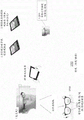
Fig. 1 is a diagram illustrating media focusing.
Fig. 2 includes an information banner on the media-focusing wearable optics.
Fig. 3 is a block diagram of wearable optics used in a music environment, such as an MP3 player.
Fig. 4 is a block diagram showing wearable optics used as a cell phone.
Fig. 5A is a block diagram illustrating the cellular phone circuit of fig. 4.
Fig. 5B illustrates perceptual optimization using optical and perceptual parameters.
Fig. 5C illustrates an enhanced digital goggle architecture.
FIG. 6 illustrates portions of an eye that may be used with an eye tracking mechanism of an embodiment.
Fig. 7 illustrates a social networking application for use with a wearable optical device.
FIG. 8 illustrates a messaging application for use with a wearable optical device according to one embodiment.
FIG. 9 illustrates wearable optics for use by a sporting spectator, according to one embodiment.
FIG. 10 illustrates wearable optics for use by a sports athlete in accordance with one embodiment.
FIG. 11 illustrates an augmented reality information, navigation and advertising application for use with a wearable optical device.
Fig. 12 illustrates an augmented reality information patient data application for use with a wearable optical device for use with a remote device.
Fig. 13 illustrates a shading control application for use with a wearable optical device.
FIG. 14 illustrates an augmented reality application for use with a wearable optical device.
FIG. 15 illustrates one physical gaming application for use with a wearable optical device.
FIG. 16 shows a first embodiment of an online/mobile gaming application for use with a wearable optical device.
FIG. 17 illustrates a second embodiment of an online/mobile gaming application for use with a wearable optical device.
Fig. 18 shows shading control using a wearable optical device.
Fig. 19 shows an optical/perceptual operating system with wearable optics.
Fig. 20 depicts one embodiment of a digital architecture of a wearable optical device.
Fig. 21 shows an embodiment of a system simulator for use by developers of applications and new lenses or promotions for wearable optics.
Fig. 22A to 22F show an embodiment of reverse shading using a wearable optical device.
FIG. 23 illustrates one embodiment of eye tracking illumination and enhanced efficiency using wearable optics.
Fig. 24 illustrates one embodiment of real-time augmented reality overlay using wearable optics.
Detailed Description
The present invention relates generally to wearable optics, and more particularly to wearable optics that include additional functionality. The following description is presented to enable one of ordinary skill in the art to make and use the invention and is provided in the context of a patent application and its requirements. Various modifications to the preferred embodiments and the generic principles and features described herein will be readily apparent to those skilled in the art. Thus, the present invention is not intended to be limited to the embodiments shown, but is to be accorded the widest scope consistent with the principles and features described herein.
A system and method according to the present invention relates to various ways of enhancing the utility of the wearable optics.
To describe the features of the present invention in more detail, reference is now made to the following descriptions taken in conjunction with the accompanying drawings.
1. Media focus 100
Fig. 1 is a diagram illustrating a media focus 100. Media focus 100 includes a message box 102, receiver 104, digital circuitry 106, frame 108, and lenses 110. Media focus 100 allows wearable optics to be enhanced for its primary purpose, e.g., a digital camera may be placed within the wearable optics to allow some of the images to be seen. For example, the circuitry 106 of the media focus 100 can be placed within the frame 108 of the wearable optics. The lens 110 may have a fully reflective surface or a partially reflective surface using an LCD or the like. In fact, the wearable optics may look like see-through glasses, but by using circuitry 106 within the wearable optics, the wearable optics is in fact a media focus. Additionally, the wearable optics may incorporate a camera to project the user onto a second lens to achieve a perspective effect.
In a preferred embodiment, an information banner 102 visible to the user is provided across a portion of the wearable optics. This information field 102 is used to convey various types of information.
Fig. 2 includes an information banner 102' on the media-focusing wearable optics. The information bar 102' may be a stock ticker (stock marker) that rolls across the top portion of the wearable optics, as shown in fig. 2. Although the information banner 102' is shown as displaying a stock ticker, other kinds of information may be displayed in the information banner, such as song title, lyrics, etc. This information column is called E-focal. This information may be provided from the digital receiver by an FM station, by a cellular radio, or by an MP3 player. Further functionality of E-focal will be described in detail with respect to handset enhancements as well as music player enhancements.
One of these key features of the media focus 100 is the use of media focus to enhance the user's primary function, that is, to be able to see objects more accurately and clearly. In such an environment, for example, it is possible to have a zoom feature circuit that allows the wearable optics to be used as binoculars. This would allow the user to see objects closer based on certain activities of the user. For example, there may be a plurality of eyes or pressure sensors on the wearable optics that will activate the binocular circuit of the eyeglasses, which may receive visual data through a camera, CCD receiver, or the like.
In the preferred embodiment, the circuitry 106 would be located somewhere in the frame of the eyewear in order to provide this functionality, and as circuits become smaller and devices become smaller, it is increasingly easier to know that circuitry for such functions would be directly embedded within the device. The circuitry 106 in the device may be, for example, a plurality of eye sensors (which may be pressure sensors), capacitive sensors, or some other type of sensor for allowing eye-directed activity. For example, an eye movement sensor may be used to activate and control binocular glasses. Similarly, a digital camera may be placed on the glasses, which would allow the same kind of technology to take pictures directly by a person.
In a similar state, the glasses may be used as a normal corrective lens glasses using digital imagery, such that, for example, a user has a particular prescription that they clearly view a subject using their normal prescription glasses. When the user's eyes change, the following will be possible: a dispenser will be able to download a new prescription to the wearable optics so as to provide a digital conversion of image information compatible with the new prescription.
Further, in a preferred embodiment, a method for sensing and controlling digital media may be implemented in a variety of ways. For example, an activity of the eyes will itself control the activity of the media focus. Thus, for example, if the idea is to zoom the image, the eye will blink twice. It would also be possible to detect facial and eye movements (e.g., strabismus) as well as changes in the pupils and irises.
In a further embodiment, an eyepiece according to the present invention would likely function within a client/server model or a Bluetooth (Wi-Fi) model. Using the client/server model and bluetooth Wi-Fi will make it possible to display live news or topical reports (such as financial reports) from the internet or similar sources, for example, on the eyepiece. This will also allow parts of the circuitry to be remotely located, thus requiring less circuitry in the wearable optics.
The wearable optics may also include a trademark, for example, law enforcement officers may have their eyeglasses decorated with "Police (Police)", "chief officers (Sheriff)", "MP", etc.; younger people may have their eyepieces decorated with words and images etc. that reflect their favorite actors; sports teams may discount for sale of eyepieces and the like with team assembly patterns. They may also be purchased by a company, decorated with company brands and distributed as retirement gifts, and the like.
2. Music environment
Fig. 3 is a block diagram of wearable optics 300 used in a music environment, such as an MP3 player. Fig. 3 includes wearable optics 300, an information banner 302, MP3 player circuitry 304, storage area 306, frame 308, and one or more lenses 310. Another environment as already described above is a music environment. It would be desirable to provide music glasses in which an MP3 player on an IPod or the like is incorporated into the wearable optics in either a wired environment or a wireless environment. By using this type of system, multiple users can be networked via an MP3 player type environment within a hot zone, or the like, which would allow one to download whatever music is needed through the eyepiece. The system may allow downloadable music to be available that may be selected by the speech recognition system via a scroll bar or the like.
For example, by connecting to a client-server network or a bluetooth Wi-Fi facility, the eyepiece may link to a multimedia network, authorize downloads, and pay for selected music. By this means, access to a plurality of libraries may be provided for selecting music.
It would also be possible to provide access to streaming audio media. Further, access to multimedia libraries and the like may be provided via a client/server model.
Information may be received via a digital client/server model implemented to work with an iPod or MP3 player. Similarly, bluetooth wireless technology may be used to provide access to music and live audio sources.
The wearable optics may also be used in conjunction with wireless technology to allow a user or users to participate in a single or group karaoke performance simultaneously. The wearable optics may specifically be used to display the lyrics, melody, notes, song name or other associated references of a song.
It would also be possible to receive and listen to AM or FM radio signals via one AM/FM radio tuner connected to the wearable optics hardware.
In this type of environment, the headset may be either digital or analog. The user need not have, for example, 10000 songs. They may register in an online song (in-song) virtual network library when entering a hotspot. Thus, the local storage area 306 may be limited. In addition, this will provide location identification information for the person using the network. These songs may be streamed as downloaded. The songs may be purchased using the wearable optics. The system may be scalable; depending on which device is being used.
3. Telecommunications environment
Fig. 4 is a block diagram illustrating wearable optics 400 used as a cell phone. Fig. 4 includes cellular telephone circuitry 402, a microphone 104, a frame 408, and one or more lenses 410. Cell phone wearable optics 400 may be implemented using digital telephone technology. Circuitry 402 within the wearable optics may be used to allow a phone number or other visual information (such as information provided by a multimedia messaging service) to be displayed on lens 410 of the wearable optics, as shown in fig. 3. Fig. 5 is a block diagram illustrating the cellular phone circuit of fig. 4. Fig. 5 includes a noise cancellation circuit 502, a speech recognition circuit 504, a caller ID circuit 506 and a speaker recognition circuit 508, and a media processing circuit 509. The phone number may be activated via digital circuitry 402 as part of media focus 100. In addition, the circuit can be made truly digital via a digital signal processor that is otherwise coupled to a camera in the environment. The above system would allow voice recording through the use of one microphone 104 and would allow voice recognition through the use of the voice recognition circuit 504, which would allow signal conditioning on the handset in a variety of ways.
The handset environment 402 provides a number of areas to be improved using existing technology. First, one of the major annoyances in handset usage is that these users must speak in a loud manner due to background noise, etc. There are a number of reasons for this problem, including the placement of the handset microphone relative to the speaker's mouth (due to the background noise mentioned above) and other problems. By strategically placing the microphone 104 on the wearable optics, such as near the nose or mouth, the user will not have to speak as loudly. The microphone may also be located in a flip-down microphone. In addition, the noise cancellation circuit 502 may be used to remove background noise. Microphone capabilities would include the advantage of using noise suppression techniques. Buttons located on the wearable optics may be used to control features thereon. Finally, the microphone 104 may use otoacoustic techniques so that the speaker will not have to speak as loudly.
In a preferred embodiment, the wearable optics will include a voice recognition circuit 504 and a caller ID circuit 506. In a preferred embodiment, the means for listening and speaking will be conventionally located in the ear pad and nose pad portions of the eyeglasses. Referring back to fig. 3, in a preferred embodiment, the electronics for the handset would be in the frame 308 of the wearable optics. In addition, the wearable optics will include a fully integrated information banner 302. Finally, a speaker recognition algorithm 508 as shown in FIG. 5 will allow only the user's speech to be recognized and the background noise to be eliminated. Thus, the unique characteristics of the speaker are provided via an audible model.
This can be performed using a variety of methods. For example, the user's speech is analyzed and the analysis is combined with noise cancellation. In another example, the user may speak softly and eliminate noise, and may use a directional microphone that takes advantage of the device location.
Similar to the media-focused and MP3 player environment, a digital client/server or bluetooth/wifi model may be adapted to link the wearable optics to external communication devices. Such devices may include digital handsets, PDAs or wifi enabled PCs or other devices. Such embodiments may enable reviewing voice mailboxes, screen-viewed email, text-to-audio email conversion, multimedia messaging services, and other data sources.
Wireless or bluetooth interconnections may also make it possible to use VOIP glasses instead of cell phones. Other features implemented through a wireless link may link the goggles to MP3 devices, ipods, printers, wireless/wired TVs, coupons, etc. Likewise, "PDA glasses" may provide a built-in time display, alarm clock calendar, a speaker, etc. that interfaces with a PC or network source.
As can be seen from the above description, digital goggles is a rapidly evolving area: from early innovations of digital eyewear with eye tracking capabilities by Lewis ('185' submitted in 2.2008), to eyewear with more complex lenses and communication/display capabilities ('556' submitted in 11.2009), to more enhancements and capabilities ('594' submitted in 4.2011). As technology advances to make sensors, cameras, processors and circuits smaller, more and more capabilities become possible to implement using digital goggles. This enhanced digital goggle can be used to address important areas ranging from excellent visual enhancement and mobile advertising to use in dental/medical procedures as well as physical and internet navigation. The application and value of the enhanced eyewear is further enhanced when combined with augmented reality, social networking, messaging, and communications.
With the introduction and use of new materials for lenses and filter integration, new enhancements and capabilities of the digital eyewear can be further realized. In the case of implementations using one or more layers of lens material and based on passive or active display or projection, these materials include OLEDs, LEDs, transparent LEDs, flexible LEDs, crystals, prisms, holographic, polarizing, and semi-transparent materials, etc. to electro-refractive, electro-diffractive, electro-reflective, compound refractive materials, etc.
With these new capabilities, an important new set of optical and perceptual parameters can be measured and used as input, control or feedback elements that further enhance the use and value of the eyewear and lead to important improvements that can be used for teaching, sports, health and improved perception.
Thus, systems and methods according to embodiments are disclosed that provide the enhanced features of wearable optics. For a more detailed description of these features and embodiments, reference is now made to the following descriptions taken in conjunction with the accompanying drawings. One key feature associated with these enhancements is the provision of a variety of perceptual parameters that can be used for the wearable optics. Examples of perceptual parameters include, but are not limited to: optical representation, speech, brain waves, environmental, audio, video, navigational, augmented reality, algorithmic, spatial, cognitive, explanatory.
Fig. 5B illustrates a perceptual optimization system 550. The perception optimization system 550 receives a variety of inputs (including optical parameter measurements, real world inputs, digital media inputs, expression parameter measurements, optical parameter measurement feedback, other parameter measurements) to provide a plurality of wearable optics visual display elements. The plurality of optical parameter measurements include, for example, eyelash, pupil, cornea, lens, iris, eyelid, retina measurements. The plurality of real world inputs may be inputs from one or more microphones or cameras, for example. The digital media input may be, for example, from digital audio, digital video, graphics, images, and augmented reality.
Other perceptual parameters may be, for example, smell, touch, brain waves, temperature/humidity of the user, environmental conditions in the vicinity of the user. The optical feedback may be provided by the received information about the retinal/iris dynamics and/or the lens eyelash dynamics.
Fig. 5C illustrates a wearable optics architecture 560 according to one embodiment. The architecture includes a frame 562 that includes sensors located on different areas thereof. The plurality of biometric sensors includes a blood pressure sensor 617, a temperature sensor 618, EEG sensors 616, and the like. A plurality of environmental sensors 615 are also provided. There are multiple microphone sensors 606, 607, 611 on different areas of the frame. The frame 562 includes rear, front and side cameras 606, 607, 611 for detecting objects. A lens display 601 is located within the lens. A display projector 620 is disposed on the frame to project images on the lens display 601. The lens display 601 may be a single unit or multi-unit lens. On the beam of the architecture 560 there are a plurality of infrared sensors 602 and one directional lighting unit 603. There are face and mouth motion sensors 604 and or cameras located on the lens carrier of the framework 560. There is one speaker and one extendable speaker 610 that is located on the frame when worn. The speaker 610 may be held in place by a headband. A concha speaker// vibrating element 612 is provided on the frame. A control communication unit 608 is used to control the architecture 560. A power supply unit may be used to enable the architecture. Typically, the power supply unit 613 comprises a rechargeable battery. The battery may be charged via a connector such as, but not limited to, a USB connector to a charging device, such as a laptop, tablet or desktop PC. Additionally, the device may be solar powered by a solar cell that is placed on the device or may be placed on an article of clothing (i.e., such as a hat, shirt, or pants) to facilitate charging thereof. The architecture 560 includes a directional lighting unit 603, olfactory sensors 605, and a malleable user microphone 619.
In one embodiment, the sensors may include any one or any combination of the following: a gyroscope, an accelerometer, a torque sensor, a weight sensor, a pressure sensor, a magnetometer, a temperature sensor, a light sensor, a camera and a microphone, a GPS, a wireless detection, an altitude sensor, a blood pressure, a heart rate sensor, a biometric sensor, a Radio Frequency Identification (RFID), a Near Field Communication (NFC), a mobile communication, a Wi-Fi, a strain gauge, a fingerprint sensor, an olfactory sensor, a gas sensor, a chemical sensor, a color sensor, a sound sensor, an acoustic sensor, an ultraviolet sensor, an electric field sensor, a magnetic field sensor, a gravity sensor, a wind speed sensor, a wind direction sensor, a compass sensor, a geo-locator sensor, a polarized light sensor, an infrared emitter sensor.
This architecture can be used with a conventional mobile operating system, such as Android or IOS, or with a new operating system, eye-optics or perception operating system (eyePOS), that incorporates optical and perception parameters for further capabilities and enhanced perception. By using this approach and capability set, a whole new class of custom applications ("apps") can be created using standard mobile operating systems or eyePOS and an eyePOS simulator to add a variety of valuable applications and enhanced awareness on one side that can improve human learning, entertainment, and health to a new navigation system (physically linked and searched for links). To describe these features in more detail, reference is now made to the following description.
According to one embodiment, a method and system include using dynamic eye tracking by a wearable optical device; wherein a plurality of parameters personalized to the user may be provided based on the dynamic eye tracking. The method and system include providing enhancement using objective and subjective quality criteria based on a plurality of perceptual parameters. Such as any one of the following and any combination thereof: optical representation, speech, brain waves, environmental, audio, video, navigational, augmented reality, algorithmic, spatial, cognitive, explanatory. The wearable optical device uses a plurality of perceptual parameters to control any one or any combination of: mimic, amplify or expand a user-perceived physiological function.
The wearable optics may include one or more inserts into the eyepiece. These include four-state eyepieces. Shading control may be used on the wearable optics. The shading control is provided by one or more projectors within the wearable optical device. An occlusion effect may be projected on a lens of the wearable optics. The shading is provided on a lens of the wearable optical device, wherein the surrounding area is blocked or reversed. The light blocking is provided by a polarizing filter. The shading control may be provided by the lenses within the wearable optical device. The shading can be controlled using a plurality of optical parameters. The optical parameters include any one or any combination of the following: eyelash, pupil, cornea, lens, iris, eyelid, and retina measurements. Materials that can electrically control any one or any combination of the following are used for the dynamic eye tracking: the chromaticity, refraction, diffraction, light transmission, reflection properties of the wearable optics. The lens may be any one or any combination of the following: transparent LCD, LED, OLED, flexible LED, flexible OLED, transparent substrate, semi-transparent substrate, prism-based, holographic, electroluminescent, electrically reflective, dynamic filter material.
The wearable optical device includes an electrochromic material. In a system and method according to one embodiment, one or more elements are used within the wearable optics to provide image information into the eye. The one or more elements include any one of a lens projector, a retinal projection, or any combination thereof. The retinal projection or projector plus prism provides the occlusion.
The wearable optics include shading controls for the eyewear. In the wearable optics, portions of an image viewed by the wearable optics may be shaded to control brightness. The lenses of the wearable optical device may be controlled polarization lenses, transparent OLED lenses, or projection and prism lenses.
These parameters may include any one or any combination of the following: a plurality of prescriptions, zoom features, microscope features, magnification features, retinal projection features to improve a user's vision. The wearable optics may be used in a simulator. In one embodiment, the focusing of the wearable optics is used in conjunction with the dynamic eye tracking.
These parameters may include any one or any combination of the following: zoom, microscope, magnification, illumination features; a retinal projection feature. In one embodiment, a 360 degree view may be provided. The 360 degree view may be any one of a left-right translation, an up-down translation, a three-dimensional rotation, or any combination thereof.
In another embodiment, an illumination feature is directed to a particular region based on the dynamic eye tracking mechanism. A wearable optics camera feature can filter certain light waves to obtain multiple controlled views or visual effects. The filtering features may include controlling noise reduction, polarization, and creative effects. The wearable optics feature may include stability controls that control the focus of the face or object. In one embodiment, multiple optical parameters may be used. The optical parameters include any one or any combination of: eyelash, pupil, cornea, retina, lens, iris measurements. One embodiment may include detecting head motion. A sonic mechanism may be used within the wearable optics. An electroencephalogram mechanism may be used within the wearable optical device. A magnetic wave mechanism may be used within the wearable optical device.
The wearable optical device may be used in a variety of environments including, but not limited to, sports, gaming, airborne gaming, education, military, fire fighting, medical dentistry, and the like. For a more detailed description of the features of the present invention, reference is now made to the following descriptions taken in conjunction with the accompanying drawings
FIG. 6 illustrates portions of an eye that may be used with an eye tracking mechanism of an embodiment. In one embodiment, the iris, retina, cornea, pupil, eyelash, and lens may all be used alone or in combination to implement the dynamic eye tracking mechanism.
According to one embodiment, social networks may be advantageously used with the wearable optical device. Fig. 7 illustrates a social networking application 700 for use with a wearable optical device. Com and other networks and the internet are connected to the wearable optical device.
An individual, such as "friends," may be identified by the wearable optics with a high brightness. Information about an individual may be gathered by using the eye used by the wearable optics architecture. In one embodiment, the individual may be selected. The individual may be identified in a variety of ways, such as using facial recognition, targeted individual information, GPS, RFID, NFC, optical information, voice recognition, and mobile location.
Fig. 8 illustrates a messaging application 800 for use with a wearable optical device according to one embodiment. In this embodiment, the information is transmitted via mobile, text, R2R, internet, wi-Fi, facebook messages, twitter's tweets. The wearable optics may communicate using R2R, NFC, wi-Fi, internet. It is possible to speak using one microphone and multiple sensors near the face, chin and nose can be used to provide control of the messaging application. In addition, lip action and lip reading can be used to transmit speech in a silent and confidential manner. An individual may be targeted using a plurality of selected eye movements.
Fig. 9 shows wearable optics 900 for use by an athletic sporting spectator, in accordance with one embodiment. Multiple networks, such as Twitter, facebook, the internet, are connected to the viewer. For example, the spectator may see the person holding the ball and the course of the ball during the game. The person holding the ball and the position of the ball are highlighted. The adaptation information may be overridden from the scores of other games. Information about the position of the american football during the game (line of fight, first line of attack). Video highlighting of the game and augmented reality media may be provided.
FIG. 10 illustrates a wearable optical device 1000 for use by a sports athlete in accordance with one embodiment. Multiple networks such as Twitter, facebook, coach/trainer communication, and other player communications are connected to the player. For example, the viewer may see a curved ball being struck at 102 mph. The trajectory of the ball is highlighted.
Fig. 11 illustrates an augmented reality information, navigation and advertising application 1100 for use with a wearable optics device. In this embodiment, the information is transmitted via mobile, text, R2R, internet, wi-Fi, facebook messages, twitter's tweets. The wearable optics may communicate using mobile, R2R, NFC, wi-Fi, internet. In one example, the wearable optical device is used in a vehicle. In this example, the wearable optics include a speaker microphone and a rear camera located on the headphones and also located, for example, on the rear of a vehicle. Augmented reality real-time information is provided. For example, augmented reality real-time information is provided that the vehicle is traveling at 62 mph.
There may also be augmented reality mirror live video from the rear camera of the car. For a sign read as "Detour 1Mile," the sign is displayed as an emergency augmented reality sign from a state/federal source, which may also provide additional information.
In another example, the next export, "McDonald's Free Coffee," is treated as an augmented reality real-time advertisement. "stager Road 1 Mile" will also be considered as an augmented reality marker, while the voice message "Next turn stager Road 1Mile (rd.1 Mile)" is transmitted to the driver together, thus constituting an augmented reality GPS and navigation system.
Fig. 12 illustrates an augmented reality information patient data application 1200 for use with wearable optics for use with a remote device. In this embodiment, the information is transmitted via mobile, text, R2R, internet, wi-Fi, facebook messages, twitter's tweets. The wearable optics may communicate using mobile, R2R, NFC, wi-Fi, internet.
Patient records and internet technology information are connected to the eyepieces and microphone of the person using the wearable optical device. Medical features are identified using an augmented reality zoom window. Augmented reality patient data is made available to the person via the goggles. There may also be a remote device camera used on the drill of a dentist, for example. The dentist can use the dynamic eye tracking mechanism to focus on the correct tooth, for example.
The coverage of the tooth with x-rays can be seen using augmented reality. An augmented reality overlay of internet searches on dental records and dental treatments is available. The dentist can use one remote bur with augmented reality. Illumination and zooming may also be used with the augmented reality window.
Fig. 13 illustrates a shading control application 1300 for use with a wearable optical device. In this embodiment, the information is transmitted via mobile, text, R2R, internet, wi-Fi, facebook messages, twitter's tweets. The wearable optics may communicate using mobile, R2R, NFC, wi-Fi, internet. The shade setting may be selected automatically via eye movement or by a push button on the goggle frame. The shading may be uniform across the goggle lens, or concentrated in one or more particular regions of the lens.
In one embodiment, one bulb/flash 1302 projects light to the eye 1310. The camera 1306 and eye sensor 1308 pick up the light. The lens 1304 can be any one or any combination of the following: transparent LCD, LED, OLED, flexible LED, flexible OLED, transparent substrate, semi-transparent substrate, prism-based, holographic, electroluminescent, electrically reflective, dynamic filter material.
Light may be blocked in one particular region 1312 using the wearable optics. The camera 1306 determines the position of the light to be occluded (in real time). The eye sensor 1308 determines the position of the eye/pupil/retina (in real time). The camera 1306/eye sensor 1308 determines the line of sight between the light to be occluded and the eye 1310 and the intersection area on the lens 1304 (in real time) or the area where the occlusion is projected from one projector embodiment.
Fig. 14 shows an augmented reality application 1400 for use with wearable optics 1410. In this embodiment, the information is transmitted via mobile, text, R2R, internet, wi-Fi, facebook messages, twitter's tweets. The wearable optics 1410 may communicate using mobile, R2R, NFC, wi-Fi, internet.
In one embodiment, an augmented reality keyboard 1404 appears that is selected by looking at the phone/item and then blinking, etc. An Augmented Reality (AR) keyboard 1404 controlled by the dynamic eye tracking mechanism is used. An infrared camera 1402 is used to sense the position of either hand, hand motion, finger position, finger motion of the user on the AR keyboard, such as key highlighting and key click sounds. There is an augmented reality display 1406 on the lens that is an enlargement of the cell phone display. There is also an augmented reality keyboard shown on the lens.
FIG. 15 shows one physical game application 1500 for use with wearable optics 1510. In this embodiment, the information is transmitted via mobile, text, R2R, internet, wi-Fi, facebook messages, twitter's tweets. The wearable optics 1510 may communicate using mobile, R2R, NFC, wi-Fi, the Internet.
In one embodiment, the person wearing the wearable optics 1510 may analyze game strategy, count cards, determine scores, make analyses (of game statistics), and analyze the faces of other players using an augmented reality overlay 1502 and facial recognition.
FIG. 16 shows a first embodiment of an online/mobile gaming application 1600 for use with wearable optics 1610. In this embodiment, the information is transmitted via mobile, text, R2R, internet, wi-Fi, facebook messages, twitter's tweets. The wearable optics 1610 may communicate using mobile, R2R, NFC, wi-Fi, internet.
The player and opponent have augmented reality cards in them. An augmented reality card game is used. Because of the augmented reality and communication links, these players need not be present at the same location. These AR cards may be lifted by hand motion. There is a physics-adjusted augmented reality card motion and dynamics. In one embodiment, there may be one virtual game board, one background, and one playard.
An infrared camera 1602 is present on the glasses to measure and determine hand and finger position and movement. There is an augmented reality scene or dynamic overlay 1612 that can be seen on the lenses.
FIG. 17 shows a second embodiment of an online/mobile gaming application 1700 for use with wearable optics 1710. In this embodiment, the information is transmitted via mobile, text, R2R, internet, wi-Fi, facebook messages, twitter's tweets. The wearable optics 1710 may communicate using mobile, R2R, NFC, wi-Fi, internet.
The scene seen by the player may be a real-world video game scene. The scene may also be used as an augmented reality video game scene (e.g., in the case of a mobile phone). In addition, the scene may also be used as a full 3-D real-time augmented reality game/battlefield that the player sees. The player may use an augmented reality game controller. An infrared camera is present on the glasses to measure and determine the position and movement of the hand and fingers on the AR game controller. See a multi-augmented reality scene, AR game controller, AR gun, or AR remote control overlay 1712 on the lenses of the glasses.
Fig. 18 shows a shading control mechanism using a wearable optical device. In this embodiment, there are one or more cameras 1806 that measure changes in the eye (e.g., pupil or retina) and send the information to a processing system. Thereafter, the processing system 1802 can control a display on the lens 1804 to provide shading.
Fig. 19 shows an optical/perceptual operating system 1900 with wearable optics. As seen, a number of applications 1902-1910 interface with a processing system. The processing system includes a CPU, memory, computer control, and a CPU update system 1912.
These applications include, but are not limited to: an eye prescription 1902, shading 1904, a glare application 1906, GPS 1908 for navigation of a vehicle, and a medical application 1910. The system will include a perception measurement/generator 1914. These would include, but are not limited to, calibration software, augmented reality software, entertainment software video/audio conferencing software, and external communications/databases. The system will also include one or more device drivers. Including, but not limited to, a display driver 1916, an optical/sensor driver 1918, an operating system driver 1920, a network driver 1922, an external remote object driver 1924, and a game/entertainment driver 1926.
Fig. 20 depicts one embodiment of the digital architecture of a wearable optical device 2000. In this embodiment, the wearable optical device goggles include mobile/smartphone circuitry/external data communication/and circuitry for communicating data via mobile, text, R2R, internet, wi-Fi, facebook messages, twitter's tweets, along with contact with a plurality of external network platforms/data/media sites 2016. The wearable optics comprises a processing system 2002 with memory storage, sensors 2006 for optical and perceptual measurement, circuitry 2004 to control the optical display and perceptual generation needs of the device, and interfaces 2008 to remote devices such as tools, professional video cameras, GPS, mobile phones, wearable devices, etc.
In this embodiment, different types of application software ("apps") 2018 may be running on the wearable optics 2000, including shading control applications, focusing and user eye adjustment prescriptions, and augmented reality applications for games such as american football. An internet browser 2010 may be used that drives internet navigation using optical or perceptual parameters such that eye movements or facial expressions may accelerate the browsing process of desired information. The wearable optical device 2000 includes a system browser 2012 having a file storage area that is accessible on the device or via one of the networks to the device.
The device 2000 may be powered by a separate battery (not shown). The battery may be charged via a connector such as, but not limited to, a USB connector to a charging device, such as a laptop, tablet or desktop PC. Additionally, the device 200 may be solar powered by a solar cell that is placed on the device 2000 or may be placed on an article of clothing (i.e., such as a hat, shirt, or pants) to facilitate charging thereof.
Fig. 21 shows an embodiment of a system simulator 2100 for use by developers of applications and new lenses or promotions for wearable optics. In this embodiment, there is a simulator 2102, a lens simulator 2104, a display 2114 and a goggle simulator 2116 for the operating system. A plurality of optical/perceptual measurements 2106, camera signals and other sensors and measurements are inputs to the simulator. The developer apps or new lens may then be tested for different types of wearable options with different types of systems, including iOS, andriod, and general or optimized optical/perceptual operating systems.
Fig. 22A-22F illustrate one embodiment of reverse shading using a wearable optical device. Fig. 22A illustrates the problem of glare caused by ambient light, which reduces the visibility of the screen of an object, such as a mobile phone or laptop. Fig. 22C depicts iris/pupil constriction due to brightness, which degrades the viewing of a target object, such as a phone screen, by the retina/cornea and brain. In fig. 22E, the screen appears dark because the ambient light is much brighter than the phone screen.
Fig. 22B illustrates the selection of a target object, such as in one phone screen, via eye or by multiple preferences, rules, camera image capture, and object recognition. Fig. 22D illustrates eye detection and capture of the location and image of the object by a camera on the goggle. Fig. 22F illustrates the resulting removal or reduction of glare and increase in visibility of the subject, with an opaque or translucent background that follows the subject's surrounding area in real time, as seen by the user of the wearable optics.
FIG. 23 illustrates one embodiment of eye tracking illumination and enhanced efficiency using wearable optics. Using the eye sensor and the camera, a line of sight and a focal length may be determined and used to control a directional illumination source such that the illumination source illuminates an area corresponding to an area focused by a user of the wearable optical device.
Fig. 24 shows one embodiment of a real-time augmented reality overlay 2400 using wearable optics. In this embodiment, the information is transmitted via mobile, text, R2R, internet, wi-Fi, facebook messages, twitter's tweets. The wearable optics may communicate using mobile, R2R, NFC, wi-Fi, internet. In one example, the wearable optical device is used in a vehicle. In this example, the driver's goggles use augmented reality to cover advertising signs that may be personalized to the user that appear as if they are normal roadside billboards. In this example, a real-time updated augmented reality hazard sign is posted ahead of a road hazard by generating augmented reality signs using information from networks connected to the wearable eyewear device. This example also shows the translation of the navigation warning and the plurality of advertising signs from english to spanish in real time using the enhanced implementation of the wearable optical device.
Thus, systems and methods according to embodiments are disclosed that provide the enhanced features of wearable optics. For a more detailed description of these features and embodiments, reference is now made to the following descriptions taken in conjunction with the accompanying drawings. One key feature associated with these enhancements is the provision of a variety of perceptual parameters that can be used for the wearable optics. Examples of perceptual parameters include, but are not limited to: optical representation, speech, brain waves, environmental, audio, video, navigational, augmented reality, algorithmic, spatial, cognitive, explanatory.
While the invention has been described in terms of the illustrated embodiments, those skilled in the art will readily recognize that there could be variations to the embodiments and those variations would be within the spirit and scope of the present invention. Accordingly, many modifications may be made by one of ordinary skill in the art without departing from the spirit and scope of the appended claims.
Claims (417)
1. A wearable optical device, comprising:
a lens; and
a dynamic eye tracking mechanism in communication with the lens; and
one or more camera components and one or more communication components to provide augmented reality;
wherein a plurality of parameters personalized to the user can be provided based on the dynamic eye tracking, the enhancement being provided using objective and subjective quality criteria based on a plurality of perceptual parameters;
wherein at least one of the used plurality of perception parameters is iris dynamics; and
one or more projectors within the wearable optics provide shading control using a polarizing filter to project shading effects on a lens of the wearable optics.
2. The wearable optics device of claim 1, wherein an acoustic wave mechanism is used within the wearable optics device.
3. The wearable optics device of claim 1, wherein the wearable optics device is used to determine the alcohol concentration of the user.
4. The wearable optics apparatus of claim 1, wherein a digital client-server or bluetooth or wifi model is adapted to link the wearable optics apparatus to external communication devices.
5. The wearable optical device of claim 1, wherein a plurality of sensors are used to provide sensory inputs to the device, wherein said sensors comprise any one or any combination of: a gyroscope, an accelerometer, a pressure sensor, a torque sensor, a weight sensor, a magnetometer, a temperature sensor, a light sensor, a camera and microphone, a GPS, wireless detection, an altitude sensor, blood pressure, a heart rate sensor, a biometric sensor, radio Frequency Identification (RFID), near Field Communication (NFC), mobile communication, wi-Fi, a strain gauge, a fingerprint sensor, an olfactory sensor, a gas sensor, a chemical sensor, a color sensor, a sound sensor, an electric field sensor, a magnetic field sensor, a gravity sensor, a wind speed sensor, a wind direction sensor, a compass sensor, and a geo-locator sensor, and
the sensor includes an earpiece including a speaker including a microphone for canceling noise.
6. The wearable optical device of claim 1, wherein the perception parameters include any one of the following and any combination thereof: optical representation, brain waves, environmental, audio, video, navigational, augmented reality, spatial, cognitive, various facial emotions.
7. The wearable optics device of claim 6, comprising a plurality of sensors located on a plurality of areas on a frame of the wearable optics device, wherein the sensors comprise any one or any combination of: a gyroscope, an accelerometer, a pressure sensor, a torque sensor, a weight sensor, a magnetometer, a temperature sensor, a light sensor, a camera and microphone, a GPS, wireless detection, an altitude sensor, blood pressure, a heart rate sensor, a biometric sensor, radio Frequency Identification (RFID), near Field Communication (NFC), mobile communication, wi-Fi, a strain gauge, a fingerprint sensor, an olfactory sensor, a gas sensor, a chemical sensor, a color sensor, a sound sensor, an electric field sensor, a magnetic field sensor, a gravity sensor, a wind speed sensor, a wind direction sensor, a compass sensor, and a geo-locator sensor.
8. The wearable optics device of claim 1, wherein the wearable optics device is used in conjunction with eye diagnosis, eye examination;
wherein the eye test of the wearer comprises controlled corneal or ocular lens measurements of muscles on the eye muscles, the side of the face, or their equivalent.
9. The wearable optics device of claim 1, wherein the wearable optics device includes filtering certain light waves to obtain a plurality of controlled views or visual effects.
10. The wearable optics of claim 9, wherein the filtering includes controlling illumination noise reduction, polarization, and creative effects.
11. The wearable optics device of claim 1, wherein the wearable optics device is for illumination, wherein illumination is controlled by one or more of: manually, via eye control, via voice control.
12. The wearable optics device of claim 11, wherein shading control is provided by at least one eye sensor and one camera.
13. The wearable optics device of claim 11,
a camera determines a position of light to be occluded, an eye sensor determines a position of an eye, and the camera and the eye sensor determine a line of sight between the light to be occluded and the eye.
14. The wearable optics device of claim 1, wherein the wearable optics device is used to identify who is actually speaking.
15. The wearable optics device of claim 1, wherein the wearable optics device is used in conjunction with a social network or external database to identify characteristics of those or that content viewed by the user.
16. The wearable optics device of claim 1, wherein muscle movement is used as a surrogate for speech; alternatively, the first and second electrodes may be,
where multiple perceptual measurements are used, identity information is provided where the nose can be a voice carrier.
17. The wearable optics device of claim 1, wherein the dynamic eye tracking is used for navigation and multiple fingers are used to make selections.
18. The wearable optics device of claim 17, wherein said wearable optics device comprises a click navigation mechanism using the fingers.
19. The wearable optics device of claim 1 comprising an augmented reality display, the augmented reality display capable of use in conjunction with online procurement.
20. The wearable optics device of claim 19, wherein the augmented reality display can be used in conjunction with RFID communication or NFC communication.
21. The wearable optics device of claim 1, wherein a plurality of algorithms are provided to transform the non-visible spectrum into visible information.
22. The wearable optics device of claim 1, wherein the parameters are medical features related to the user.
23. The wearable optics device of claim 1, wherein the parameter is a plurality of dental characteristics of the patient, wherein a plurality of optical parameters are used, the optical parameters being used to detect pain or a plurality of other dental conditions.
24. The wearable optics device of claim 1, wherein the wearable optics device is used to determine symptoms of sleep deficiency.
25. The wearable optics device of claim 1, wherein the wearable optics device is used in conjunction with a brain wave meter.
26. The wearable optics device of claim 1, wherein the wearable optics device comprises a plurality of sensors located on a plurality of areas on a frame of the wearable optics device, the sensors comprising any one of, or any combination of:
a gyroscope, an accelerometer, a pressure sensor, a torque sensor, a weight sensor, a magnetometer, a temperature sensor, a light sensor, a camera and microphone, a GPS, wireless detection, an altitude sensor, blood pressure, a heart rate sensor, a biometric sensor, radio Frequency Identification (RFID), near Field Communication (NFC), mobile communication, wi-Fi, a strain gauge, a fingerprint sensor, an olfactory sensor, a gas sensor, a chemical sensor, a color sensor, a sound sensor, an electric field sensor, a magnetic field sensor, a gravity sensor, a wind speed sensor, a wind direction sensor, a compass sensor, and a geo-locator sensor.
27. The wearable optics device of claim 26, wherein the sensor comprises an earpiece connected by a wire to a frame or wirelessly.
28. The wearable optics device of claim 27, wherein the ear pieces measure ear muscles.
29. The wearable optics device of claim 1, wherein audio wave technology is used in conjunction with the dynamic eye tracking mechanism.
30. The wearable optics device of claim 29, wherein the audio wave technology comprises audio focusing.
31. The wearable optics device of claim 30, wherein the audio wave technology includes noise cancellation that is selective such that other noises are blocked.
32. The wearable optics device of claim 30, wherein the audio wave technology includes noise cancellation, the noise cancellation being selective, the selectivity being used in conjunction with a real-life application.
33. The wearable optics device of claim 30, wherein the audio wave technology includes noise cancellation, the noise cancellation being selective, the selectivity being such that audio mixing control is provided.
34. The wearable optics device of claim 30, wherein the audio wave technology includes noise cancellation that is selective such that both the sourced audio and the ambient audio are controlled to produce the effects.
35. The wearable optics device of claim 30, wherein the audio wave technology includes noise cancellation that allows for cancellation of certain ranges of sound.
36. The wearable optics device of claim 30, wherein the audio wave technology includes noise cancellation that allows for cancellation of certain sources of sound.
37. The wearable optics device of claim 1, wherein audio wave technology is used in conjunction with the dynamic eye tracking mechanism, wherein vibrations can be used with augmented reality.
38. The wearable optics device of claim 1, wherein audio wave technology is used in conjunction with the dynamic eye tracking mechanism, wherein vibration is used to enhance the use of media.
39. The wearable optical device of claim 1, wherein audio wave technology is used in conjunction with the dynamic eye tracking mechanism;
wherein the audio wave technique includes the use of a vibration detection mechanism.
40. The wearable optical device of claim 1, wherein an advertisement is provided based on a plurality of user parameters; and
wherein the wearable optical device is capable of viewing advertisements to provide viewing information to the vendor.
41. The wearable optics device of claim 1, wherein an advertisement is provided based on a plurality of user parameters.
42. The wearable optics device of claim 1, wherein an advertisement is provided based on the dynamic eye tracking mechanism.
43. The wearable optics device of claim 1, wherein advertisements are provided using any one or any combination of GPS, cellular, or other location-based systems.
44. The wearable optics device of claim 1 comprising a bar code sensor.
45. The wearable optics device of claim 1, wherein language translation is used in conjunction with the dynamic eye tracking mechanism.
46. The wearable optics device of claim 1, wherein the wearable optics device is used in conjunction with demographic information for use with any one of online media, networks, real objects, or a combination thereof; alternatively, the first and second electrodes may be,
wherein the wearable optical device is used in conjunction with demographic information collected based on the channel the user is viewing or the location the user is viewing on a display.
47. The wearable optics device of claim 46, wherein language translation is used in conjunction with the dynamic eye tracking mechanism and an overlay translation is used in an advertising medium; alternatively, the first and second electrodes may be,
wherein augmented reality GPS is used in conjunction with the dynamic eye tracking mechanism and one overlay translation is a translation overlay for a plurality of signposts.
48. The wearable optics device of claim 1, wherein the parameter comprises any one of, or any combination of: zoom feature, microscope feature, illumination feature.
49. The wearable optics device of claim 1, wherein the wearable optics device is used in a gaming environment.
50. The wearable optics device of claim 1, wherein augmented reality is used based on demographics.
51. The wearable optics device of claim 1, wherein the parameter is a plurality of dental features of a patient that can be received by a dentist using the wearable optics device to perform a plurality of dental procedures on the patient with augmented reality.
52. The wearable optical device of claim 51, wherein the dental procedures include any one or any combination of tooth drilling, tooth extraction, tooth washing, and root canal.
53. The wearable optics device of claim 52, wherein results of the dental procedures can be transmitted to one or more third parties.
54. The wearable optics device of claim 1, wherein any one or any combination of light, x-rays, or sound is used for the dynamic eye tracking mechanism.
55. The wearable optics device of claim 1, wherein shading control is used on the lens, the shading being controlled using optical parameters;
wherein the lens comprises any one or more of: transparent LCD, LED, prism-based, holographic, electroluminescent, electrically reflective, dynamically filtering, refractive materials.
56. The wearable optics device of claim 6, wherein the optical representations are images.
57. The wearable optics device of claim 6, wherein the wearable optics device uses perceptual parameters to control any one or any combination of: mimicking, amplifying or expanding a user-perceived physiological function.
58. The wearable optics device of claim 1, wherein the wearable optics device comprises one or more inserts into an eyepiece.
59. The wearable optics device of claim 58, wherein the eyepiece comprises a quad eyepiece.
60. The wearable optics device of claim 1, wherein shading control is used on the lens.
61. The wearable optics device of claim 60, wherein the shading is controlled using optical parameters.
62. The wearable optics device of claim 61, wherein the optical parameters comprise any one of, or any combination of: eyelash, pupil, cornea, retina, lens, iris measurements.
63. The wearable optics device of claim 61, wherein materials that electrically control any one or any combination of the following are used for the dynamic eye tracking: the wearable optics have colorimetric, refractive, diffractive, light transmissive, reflective properties.
64. The wearable optics device of claim 63, wherein portions of an image viewed by the lens are shaded to minimize brightness.
65. The wearable optics device of claim 1, wherein the lens comprises a plurality of controlled refractive lenses.
66. The wearable optics device of claim 1, wherein the lens comprises a polychromatic material.
67. The wearable optics device of claim 1, wherein the wearable optics device comprises an electrochromic material.
68. The wearable optics device of claim 1, wherein one or more elements are used within the wearable optics device to provide image information into the eye.
69. The wearable optics device of claim 68, wherein the one or more elements comprise any one of a lens projector, a retinal projection, or any combination thereof.
70. The wearable optics device of claim 69, wherein shading or blocking is provided by any combination of lens projector, retinal projection.
71. The wearable optics device of claim 1, wherein the wearable optics device comprises an electro-refractive material.
72. The wearable optics device of claim 1, wherein the parameters comprise any one or any combination of: a plurality of prescriptions, zoom features, microscope features, retinal projection features to improve a user's vision.
73. The wearable optics device of claim 72, wherein a plurality of optical parameters are used.
74. The wearable optics device of claim 73, wherein the optical parameters comprise any one or any combination of: eyelash, pupil, cornea, retina, lens, iris measurements.
75. The wearable optics device of claim 1, wherein the parameters comprise any one or any combination of: zoom, microscope, magnification, illumination features; a retinal projection feature.
76. The wearable optics device of claim 75, wherein an illumination feature is directed to a particular area based on the dynamic eye tracking.
77. The wearable optics device of claim 1, wherein the wearable optics device is used in a simulator.
78. The wearable optics device of claim 1, a focal point of the user of the wearable optics device used in conjunction with the dynamic eye tracking.
79. The wearable optics device of claim 1, wherein the parameters comprise any one or any combination of: zoom, microscope, magnification, illumination features; projector features, retinal projection features.
80. The wearable optics device of claim 1, wherein a 360 degree view is provided.
81. The wearable optics device of claim 80, wherein the 360 degree view can be any one of left-right translation, up-down translation, three-dimensional rotation, or any combination thereof.
82. The wearable optics device of claim 1, wherein an illumination feature is directed to a particular area based on the dynamic eye tracking mechanism.
83. The wearable optics device of claim 1, comprising stability control of object focus.
84. The wearable optics device of claim 1, wherein a magnetic wave mechanism is used within the wearable optics device.
85. The wearable optics device of claim 1, wherein the parameters can be transmitted to one or more third parties.
86. The wearable optics device of claim 1, wherein the parameters are motion information related to the user.
87. The wearable optics device of claim 86, wherein a plurality of optical parameters are used.
88. The wearable optics device of claim 87, wherein the optical parameters comprise any one or any combination of: eyelash, pupil, cornea, retina, lens, iris measurements.
89. The wearable optics device of claim 1, wherein the camera component uses any one of the following and any combination thereof: transparent LCD, LED, prism-based, holographic, electroluminescent, electrically reflective, dynamically filtering, refractive materials.
90. The wearable optics device of claim 1, wherein the wearable optics device is used by a participant in conjunction with a sporting event.
91. The wearable optics device of claim 1, wherein the wearable optics device is used by an audience in conjunction with a sporting event.
92. The wearable optics device of claim 1, wherein the parameters include a zoom feature with respect to the camera component to aid in the user's performance in an athletic event.
93. The wearable optics device of claim 1, wherein the parameters are dental features of the patient.
94. The wearable optics device of claim 93, wherein a plurality of optical parameters are used.
95. The wearable optics device of claim 94, wherein the optical parameters comprise any one or any combination of: eyelash, pupil, cornea, retina, lens, iris measurements.
96. The wearable optics device of claim 95, wherein the parameters include a zoom feature to assist a dentist in performing the dental procedures.
97. The wearable optical device of claim 96, wherein the dental procedures comprise any one or any combination of drilling, extracting, washing, and root canal of a tooth.
98. The wearable optics device of claim 1, wherein a plurality of sensors are used to provide a plurality of sensory inputs to the device.
99. The wearable optics device of claim 98, wherein the sensors are wirelessly coupled.
100. The wearable optics device of claim 98, wherein the sensors are coupled via a USB wireless connection.
101. The wearable optics device of claim 98, wherein the sensors are coupled via a bluetooth wireless connection.
102. The wearable optics device of claim 28, wherein the measurement of the auricular muscle is used to adjust acoustic volume or acoustic focus.
103. The wearable optics device of claim 1, wherein the wearable optics device comprises sensors located on areas of a frame of the wearable optics device, wherein the sensor comprises a microphone connected by a wire to the frame or wirelessly connected.
104. The wearable optics device of claim 103, wherein the microphone is used in conjunction with a camera.
105. The wearable optics device of claim 1, wherein one or more distribution networks are used by the wearable optics device.
106. The wearable optics device of claim 1, comprising an input/output (I/O) capability integrated with the wearable optics device.
107. The wearable optics device of claim 1, wherein different media can be overlaid based on the dynamic eye tracking mechanism.
108. The wearable optics device of claim 1, wherein different media can be blended based on the eye tracking mechanism.
109. The wearable optics device of claim 108, comprising a plurality of wireless inputs.
110. The wearable optics device of claim 95, wherein results of a dental procedure can be transmitted to one or more third parties.
111. The wearable optical device of claim 22, wherein the medical features include anatomical features of the patient.
112. The wearable optics device of claim 111, wherein the anatomical features of the patient can be received by a physician who performs medical procedures on the patient using augmented reality using the wearable optics device.
113. The wearable optics device of claim 1, wherein the parameters include a zoom feature to assist a physician in performing a medical procedure.
114. The wearable optical device of claim 113, wherein the medical procedures comprise surgical and/or diagnostic procedures.
115. The wearable optics device of claim 113, wherein the results of the medical procedures can be transmitted to one or more third parties.
116. The wearable optics device of claim 1, wherein an advertising target is determined by any one or any combination of eye movement, wireless position measurement, and a gyroscope.
117. The wearable optics device of claim 1, wherein a product or service of the user proximate the wearable optics device is advertised.
118. The wearable optics device of claim 1, wherein the advertisement can appear on an advertising board visible to a user of the wearable optics device.
119. The wearable optics device of claim 1, wherein the dynamic eye tracking mechanism is used to interface with a user application through the portable device.
120. The wearable optics device of claim 1, wherein an application is run on a processor of the wearable optics device.
121. The wearable optics of claim 1, wherein the dynamic eye tracking mechanism navigates using motion of the pupil of the eye.
122. The wearable optics device of claim 1, wherein the dynamic eye tracking mechanism is used to control an object.
123. The wearable optics device of claim 1, wherein the dynamic eye tracking mechanism incorporates facial recognition technology.
124. The wearable optics device of claim 1, wherein the dynamic eye tracking mechanism incorporates object recognition technology.
125. The wearable optics device of claim 1, wherein the dynamic eye tracking mechanism incorporates voice recognition technology.
126. The wearable optics device of claim 1, comprising goggles, wherein the goggles comprise a plurality of lenses.
127. The wearable optics device of claim 126, wherein the plurality of lenses comprises a plurality of controlled refractive lenses.
128. The wearable optics device of claim 126, wherein the plurality of lenses comprise any one or any combination of a polychromatic material or an electrochromic material.
129. The wearable optics device of claim 126, wherein the plurality of lenses comprise any combination of refractive or diffractive materials.
130. The wearable optics device of claim 126, wherein the plurality of lenses comprises any one of, or any combination of: transparent LCD, LED, prism-based, holographic, electroluminescent, electrically reflective, refractive, dynamic filtering.
131. The wearable optics device of claim 126, wherein the plurality of lenses is a single integrated system.
132. The wearable optics device of claim 126, wherein shading control is used on the plurality of lenses.
133. The wearable optics device of claim 1, wherein the wearable optics device is capable of viewing encoded media.
134. The wearable optics device of claim 1, wherein the wearable optics device is used with a social networking application.
135. The wearable optics device of claim 134, wherein a plurality of optical parameters are used.
136. The wearable optics device of claim 135, wherein the optical parameters comprise any one or any combination of: eyelash, pupil, cornea, retina, lens, iris measurements.
137. The wearable optics device of claim 135, wherein the wearable optics device is capable of viewing any of friends, linked-in related parties, followers, or any combination thereof by highlighting within a field of view.
138. The wearable optics device of claim 86, wherein the motion information can relate to any one of athletics, skiing, baseball, american football, tennis, basketball, and golf.
139. The wearable optics of claim 138, wherein an intended target is highlighted in the american football game.
140. The wearable optics device of claim 139, wherein a particular characteristic of the athlete is highlighted.
141. The wearable optics device of claim 139, wherein augmented reality is provided remotely.
142. The wearable optics device of claim 139, wherein an indication of the geometry of the field is provided.
143. The wearable optics device of claim 139, wherein each athlete is identified.
144. The wearable optics device of claim 139, wherein the football's possession is identified.
145. The wearable optics device of claim 138, wherein a skier using the wearable optics device can access ski movement information; the skiing movement information may include any one or any combination of multiple geological features of speed and location, elevation, and terrain of other skiers.
146. The wearable optics device of claim 138, wherein a desired target is highlighted during baseball.
147. The wearable optics of claim 146, wherein a particular characteristic of the athlete is highlighted.
148. The wearable optics device of claim 146, wherein augmented reality is provided remotely.
149. The wearable optics device of claim 146, wherein an indication of the geometry of the field is provided.
150. The wearable optics device of claim 146, wherein each athlete is identified.
151. The wearable optics of claim 1, wherein the wearable optics can be used as a telescope.
152. The wearable optics device of claim 150, wherein an object to be dilated is identified by eye movement.
153. The wearable optics device of claim 151, wherein in zoom mode, an object is followed based on the dynamic eye tracking.
154. The wearable optics device of claim 151, wherein in zoom mode, the subject is stabilized.
155. The wearable optics device of claim 138, wherein the golf ball information comprises any one of or any combination of club pick-up, topology, wind measurements, and club angle.
156. The wearable optics device of claim 1, wherein the parameters are related to information of the user.
157. The wearable optics device of claim 156, wherein the user is law enforcement personnel.
158. The wearable optics device of claim 157, wherein the information is related to use of a firearm.
159. The wearable optics device of claim 158, wherein the information comprises any one of or any combination of rangefinder information, a plurality of wind measurements, and a plurality of wind adjustment values.
160. The wearable optics device of claim 1, wherein the user is a firefighter.
161. The wearable optics device of claim 160, wherein the information presented to the user is related to use of fire fighting equipment.
162. The wearable optics device of claim 160, wherein the information presented to the user comprises GPS information about the location of a fire.
163. The wearable optics device of claim 160, wherein the information presented to the user is retrieved from a database.
164. The wearable optics device of claim 163, wherein the information includes any one of or any combination of maps, architectural drawings, and wiring schematics.
165. The wearable optics device of claim 160, wherein the firefighter uses augmented reality.
166. The wearable optical device of claim 1, wherein the user is a military personnel.
167. The wearable optics device of claim 166, wherein the information presented to the user is related to use of a firearm.
168. The wearable optics device of claim 167, wherein the information comprises any one of or any combination of rangefinder information, wind measurements, and wind adjustment values.
169. The wearable optics device of claim 168, wherein the information is retrieved from a database.
170. The wearable optics device of claim 169, wherein the information comprises any one of or any combination of maps, architectural drawings, and wiring schematics.
171. The wearable optics device of claim 166, wherein the military personnel use augmented reality.
172. The wearable optics device of claim 1, wherein the user is a security officer.
173. The wearable optics device of claim 1, wherein advertising is provided using any one or any combination of a map database and a building database.
174. The wearable optics device of claim 1, wherein augmented reality is used based on location.
175. The wearable optics device of claim 1, wherein augmented reality is used based on location conditions.
176. The wearable optics device of claim 1, wherein the dynamic eye tracking mechanism is used to control properties of an object.
177. The wearable optics device of claim 1, wherein the dynamic eye tracking mechanism is used in conjunction with radio frequency systems to control properties of a subject.
178. The wearable optics device of claim 1, wherein the dynamic eye tracking mechanism is used in conjunction with wireless systems to control properties of a subject.
179. The wearable optics device of claim 1, wherein the dynamic eye tracking mechanism is used for object recognition.
180. The wearable optics device of claim 179, wherein the properties of the object are stored in a database.
181. The wearable optics device of claim 30, wherein the audio wave technology includes noise cancellation.
182. The wearable optics device of claim 181, wherein the noise cancellation is selective.
183. The wearable optics device of claim 181, wherein the noise cancellation is based on the dynamic eye tracking.
184. The wearable optics device of claim 181, wherein there are multiple classes of noise cancellation.
185. The wearable optics device of claim 181, wherein non-object sounds are eliminated or subtracted.
186. The wearable optics device of claim 181, wherein eye tracking is used to select a person and the sounds from non-selected individuals are eliminated.
187. The wearable optics device of claim 181, wherein a speaker and a microphone are connected to devices on the outer or inner ear on the frames.
188. The wearable optics device of claim 181, wherein a headband is used to secure the speaker and microphone.
189. The wearable optics device of claim 29, wherein the audio wave technology comprises voice recognition.
190. The wearable optics device of claim 39, wherein the vibration detection mechanism is used for warning.
191. The wearable optics device of claim 39, wherein the vibration detection mechanism comprises any one of and any combination of bone conduction of the chin, skull, outer ear, and inner ear.
192. The wearable optics device of claim 29, wherein the vibration is capable of providing a high quality perception of a plurality of sounds.
193. The wearable optics device of claim 1, wherein facial motion is used in conjunction with the dynamic eye tracking mechanism.
194. The wearable optics device of claim 1, wherein a physical display appears as a blurred screen to anyone not using the wearable optics device.
195. The wearable optics device of claim 1, wherein social media features are used in conjunction with the dynamic eye tracking mechanism.
196. The wearable optical device of claim 195, wherein the social media features comprise eye contact messaging.
197. The wearable optical device of claim 195, wherein the social media features comprise real-time communications comprising any one of text transfer, instant messaging, video conferencing, tweeting, or any combination thereof.
198. The wearable optics device of claim 1, wherein virtual reading features are provided based on the dynamic eye tracking mechanism.
199. The wearable optics device of claim 198, wherein zoom control is provided.
200. The wearable optics device of claim 1, wherein a 360 degree view of media is provided based on the dynamic eye tracking mechanism to obtain information.
201. The wearable optics device of claim 1, wherein virtual reality is provided based on the dynamic eye tracking mechanism.
202. The wearable optics device of claim 1 comprising an augmented reality display.
203. The wearable optics device of claim 1, comprising an augmented reality pointing device.
204. The wearable optics device of claim 202, wherein the augmented reality display can be used in a personal computer or a mobile phone.
205. The wearable optics device of claim 1, wherein the augmented reality display is capable of being used in conjunction with a point of sale device.
206. The wearable optics device of claim 205, wherein the augmented reality display can be used in conjunction with RFID or NFC communications.
207. The wearable optics device of claim 1, wherein navigation is used in conjunction with the dynamic eye tracking mechanism.
208. The wearable optics device of claim 1, wherein augmented reality GPS is used in conjunction with the dynamic eye tracking mechanism.
209. The wearable optics device of claim 1, wherein video conferencing is used in conjunction with the dynamic eye tracking mechanism.
210. The wearable optics device of claim 1, wherein audio conferencing is used in conjunction with the dynamic eye tracking mechanism.
211. The wearable optical device of claim 210, wherein the audio conference uses any one of a caller ID name, a telephone number, or a picture, or any combination thereof.
212. The wearable optics device of claim 210, wherein multiple callers are represented by any one of a caller ID name, a phone number, or a picture, or any combination thereof.
213. The wearable optical device of claim 212, wherein an identified caller is more audible than other callers in the plurality of callers.
214. The wearable optics device of claim 1, wherein a plurality of tools are used in conjunction with the dynamic eye tracking mechanism.
215. The wearable optics device of claim 214, wherein the tools are capable of being used with remote sensors.
216. The wearable optics device of claim 215, wherein at least one of the remote sensors is a camera.
217. The wearable optics device of claim 214, wherein the tools are used with augmented reality mechanisms.
218. The wearable optics device of claim 1, wherein enhanced lip reading technology is used.
219. The wearable optics device of claim 208, wherein an overlay translation is an augmented reality overlay.
220. The wearable optics device of claim 208, wherein an overlay translation is provided in the wearable optics device using line of sight or focal distance of the lens of the user to an object to provide an augmented reality overlay.
221. The wearable optics device of claim 1, wherein the wearable optics device is used to determine what the user is viewing at any particular point.
222. The wearable optics device of claim 1, wherein the wearable optics device is used to determine what the user is viewing.
223. The wearable optics device of claim 1, wherein the wearable optics device is used to determine engagement with media.
224. The wearable optics device of claim 49, wherein the gaming environment is used with augmented reality.
225. The wearable optics device of claim 49, wherein the gaming environment is online.
226. The wearable optics device of claim 225, wherein the wearable optics device determines statistics by reference to card analysis.
227. The wearable optics device of claim 225, wherein the wearable optics device analyzes a plurality of facial expressions of a person.
228. The wearable optics device of claim 225, wherein a plurality of optical parameters are used.
229. The wearable optics device of claim 228, wherein the optical parameters comprise any one of, or any combination of: eyelash, pupil, cornea, retina, lens, iris measurements.
230. The wearable optics device of claim 228, wherein the optical parameters are used to assist in determining a strategy based on viewing a plurality of other participants.
231. The wearable optics device of claim 1, wherein the wearable optics device is used in an online environment.
232. The wearable optics device of claim 231, wherein media is incorporated to enhance experience.
233. The wearable optics device of claim 1, wherein the wearable optics device is used for illumination.
234. The wearable optics device of claim 1, wherein the wearable optics device is used for mobile payment.
235. The wearable optics device of claim 234, wherein the mobile payments are controlled by any one of manually, via eye control, voice control, or any combination thereof.
236. The wearable optics device of claim 1, wherein the wearable optics device is used to obtain identity and security information.
237. The wearable optics device of claim 236, wherein a plurality of optical parameters are used.
238. The wearable optics device of claim 237, wherein the optical parameters comprise any one or any combination of: eyelash, pupil, cornea, retina, lens, iris measurements.
239. The wearable optics device of claim 236, wherein the identity and security information is controlled by any one of manually, eye scan, brain wave, facial recognition, fingerprint scan, voice scan, or any combination thereof.
240. The wearable optics device of claim 1, wherein the wearable optics device is used as a prompter.
241. The wearable optics device of claim 1, wherein the wearable optics device is used for infrared detection or motion detection.
242. The wearable optics device of claim 1, wherein the wearable optics device is used in conjunction with demographic information.
243. The wearable optics device of claim 1, wherein the wearable optics device is used for media selection in conjunction with an augmented reality remote control.
244. The wearable optics of claim 1, wherein the wearable optics is used in conjunction with remote sensors, acting as a periscope for the user.
245. The wearable optics device of claim 244, wherein the periscope is used in an extended camera and microphone arrangement.
246. The wearable optics device of claim 1, wherein the wearable optics device comprises a stereoscopic lens.
247. The wearable optics device of claim 1, wherein the lens is in a transparent mode.
248. The wearable optics device of claim 1, wherein the wearable optics device is used with a form-filling pointing device.
249. The wearable optics device of claim 1, wherein eye position is used to activate the wearable optics device.
250. The wearable optics device of claim 1, wherein a password is used in conjunction with a username to enable the wearable optics device.
251. The wearable optics device of claim 1, wherein the wearable optics device creates vibrations around the eyeglasses.
252. The wearable optics device of claim 1, wherein the wearable optics device forms a vibration region around a frame worn by the face of the user.
253. The wearable optics device of claim 1, wherein the wearable optics device is used with a face shield, helmet, face mask, safety goggles.
254. The wearable optics device of claim 1, wherein the wearable optics device is used for glare management.
255. The wearable optics device of claim 254, wherein the wearable optics device can be used to improve a headlamp or spotlight using dimming.
256. The wearable optics device of claim 1, wherein at least one fingerprint is used to activate the wearable optics device.
257. The wearable optics device of claim 1, wherein the wearable optics device is used with windows around the user.
258. The wearable optics device of claim 257, wherein the plurality of windows are controlled by eye movement.
259. The wearable optics device of claim 258, wherein night vision is used to provide a 360 view.
260. The wearable optics device of claim 1, wherein the wearable optics device includes conference call features.
261. The wearable optics device of claim 1, wherein the wearable optics device is used for messaging.
262. The wearable optics device of claim 261, wherein the messaging comprises line-of-sight based or facial and voice recognition based messaging.
263. The wearable optics device of claim 1, wherein the wearable optics device is used in conjunction with a movie.
264. The wearable optics device of claim 263, wherein the movies comprise online movies.
265. The wearable optical device of claim 263, wherein the movies comprise any of 3D or IMAX movies.
266. The wearable optics device of claim 1, wherein the wearable optics device is used to purchase music, games, or movies.
267. The wearable optical device of claim 266, wherein the games comprise text games.
268. The wearable optics device of claim 266, wherein the games comprise any of chess, checkers, single checkers, and tic-tac-toe.
269. The wearable optics device of claim 266, wherein the games comprise physics-based games.
270. The wearable optics of claim 1, wherein the wearable optics is used with compensation algorithms in conjunction with a curved lens.
271. The wearable optics device of claim 270, wherein the curved lens is used to form a perspective view of a spatial or visual map for the user.
272. The wearable optics device of claim 270, wherein the curved lens is used to form a panoramic viewing area using lenses.
273. The wearable optics device of claim 270, wherein the curved lens is used to form a 360 degree viewing area.
274. The wearable optics device of claim 1, wherein the wearable optics device is used in conjunction with eye diagnosis and eye examination.
275. The wearable optics device of claim 1, wherein a plurality of optical parameters are used.
276. The wearable optical device of claim 275, wherein the optical parameters comprise any one or any combination of: eyelash, pupil, cornea, retina, lens, iris measurements.
277. The wearable optics device of claim 275, wherein the wearable optics device is used to control light by iris or pupil detection.
278. The wearable optics device of claim 274, wherein the wearable optics device is used for macular detection.
279. The wearable optics device of claim 1, wherein the wearable optics device uses sound detection to improve audibility.
280. The wearable optics device of claim 1, wherein the wearable optics device is used in conjunction with an ear insert for sonication.
281. The wearable optics device of claim 1, wherein the wearable optics device comprises a contact lens with shading control.
282. The wearable optics device of claim 1, wherein the wearable optics device is used in conjunction with a teslameter.
283. The wearable optics device of claim 1, wherein the wearable optics device is used in conjunction with an operating system.
284. The wearable optics device of claim 283, wherein the dynamic eye tracking is used to control the operating system.
285. The wearable optics device of claim 283, wherein a plurality of applications are used to control communication of a plurality of sensors and the wearable optics device.
286. The wearable optics device of claim 284, wherein lenses are controlled by the operating system.
287. The wearable optics device of claim 286, wherein the lens comprises a plurality of layers.
288. The wearable optics device of claim 283, wherein lens drivers and an eye cursor are controlled by the operating system.
289. The wearable optics device of claim 1, wherein the wearable optics device is used in an educational environment.
290. The wearable optics device of claim 289, wherein the dynamic eye tracking is used with a virtual textbook.
291. The wearable optics device of claim 1, wherein the dynamic eye tracking flips a page of a displayed book.
292. The wearable optics device of claim 290, wherein the dynamic eye tracking allows an instructor to determine the user's position in a given textbook.
293. The wearable optics device of claim 290, wherein the instructor is able to magnify one or more student documents.
294. The wearable optics device of claim 290, wherein a plurality of messages can be picked up by a student from or sent to an instructor.
295. The wearable optics device of claim 294, wherein the instructor is able to magnify and learn characteristics of the student.
296. The wearable optics device of claim 294, wherein the instructor is able to examine notes from one or more students.
297. The wearable optics device of claim 294, wherein the instructor is able to see what one or more students see.
298. The wearable optics device of claim 294, wherein the instructor is able to measure student engagement using optical parameters.
299. The wearable optics device of claim 289, wherein the optical parameters comprise any one or any combination of: eyelash, pupil, cornea, retina, lens, iris measurements.
300. The wearable optics device of claim 294, wherein the instructor is able to present messages and obtain feedback to one or more students in real time.
301. The wearable optics device of claim 1, wherein the wearable optics device is solar powered.
302. The wearable optics device of claim 1, wherein shading control is provided by at least one eye sensor and one camera.
303. The wearable optics device of claim 302, wherein the eye sensor and the camera determine the point at which the eye is looking through the lens.
304. The wearable optics device of claim 302, wherein the eye sensor detects bright areas on the lens.
305. The wearable optics device of claim 302, wherein the eye sensor provides dynamic tracking of each eye.
306. The wearable optics device of claim 44, wherein the barcode includes scanned based product information.
307. The wearable optics device of claim 1, wherein a plurality of applications are executed by dynamic eye tracking using one operating system.
308. The wearable optics device of claim 1, wherein browser information is performed using a browser with dynamic eye tracking.
309. The wearable optics device of claim 1, wherein a plurality of perceptual measurements are used, providing identity information.
310. The wearable optics device of claim 309, wherein muscle measurements are used for perception enhancement.
311. The wearable optics device of claim 309, wherein a central eyebrow arch, nose, eyebrow muscle group are used for focusing and zooming functions.
312. The wearable optics device of claim 1, wherein a plurality of perception parameters are used to convey a plurality of perceptions and emotions of the user.
313. The wearable optics device of claim 1, wherein a plurality of perceptual parameters are used among a plurality of video games.
314. The wearable optical device of claim 1, wherein perceptual parameters are used in a social network environment.
315. The wearable optics device of claim 1, wherein a plurality of perceptual parameters are used to provide a facial image.
316. The wearable optics device of claim 1, wherein an eyebrow, forehead sensor is used to deliver surprise or suspicion.
317. The wearable optics device of claim 1, wherein the user's cheek position is used to indicate happiness.
318. The wearable optics device of claim 1, wherein muscle movement is used as a surrogate for speech.
319. The wearable optics device of claim 309, wherein a nose bridge is used for perception enhancement.
320. The wearable optics device of claim 316, wherein a sensor on the face senses moisture content.
321. The wearable optics device of claim 316, wherein the sensory search uses mood, gaze, or eye movement to determine focus of the search.
322. The wearable optics device of claim 1, wherein an eye of the user appears natural.
323. The wearable optics device of claim 322, natural eye appearance providing the ability to display a representation of a clear view of the eye in real time.
324. The wearable optics device of claim 233, wherein a camera within the wearable optics device is used to provide a natural eye appearance.
325. The wearable optics device of claim 1, wherein a focal length of the lens is determined to improve performance of the device.
326. The wearable optics device of claim 325, wherein a focal length of an image displayed on the device is matched to a varying focal length of the lens of the user.
327. The wearable optics device of claim 1, wherein eyelash measurement is used in conjunction with the dynamic eye tracking.
328. The wearable optics device of claim 327, wherein the eyelash measurement is an active measurement.
329. The wearable optics device of claim 328, wherein the active measurement comprises transmitting infrared radiation into the eye using an infrared transmitter and capturing return information and analyzing the return information.
330. The wearable optics device of claim 327, wherein the eyelash measurement is a passive measurement.
331. The wearable optics device of claim 330, wherein the passive measurement comprises using retinal or corneal imaging and determining focal distance by analysis.
332. The wearable optics device of claim 328, wherein the active measurement uses an auto-compensation feature.
333. The wearable optics device of claim 330, wherein the passive measurement uses an automatic compensation feature.
334. The wearable optics device of claim 328, wherein the active measurement uses a calibration process.
335. The wearable optics device of claim 327, wherein the eyelash measurement adjusts a user's vision and focus requirements.
336. The wearable optics device of claim 327, wherein the lash measurement is both calibrated and operated in real-time using a virtual lens.
337. The wearable optics device of claim 17, wherein the navigation is concurrent with the selection.
338. The wearable optics device of claim 1, further comprising eye cursor control and picture selection.
339. The wearable optics device of claim 1, wherein the identification of information is enhanced.
340. The wearable optics device of claim 1, wherein reverse shading is provided when viewing a display.
341. The wearable optics device of claim 340, wherein reverse shading is provided by the polarizing filter.
342. The wearable optics device of claim 1, wherein algorithms for shading are disposed within the wearable optics device.
343. The wearable optics device of claim 340, wherein the display is used with a portable device.
344. The wearable optics device of claim 343, wherein the background of the display is shaded to allow a subject to be seen.
345. The wearable optics device of claim 340, wherein an object is not occluded but an area outside of the object is occluded.
346. The wearable optics device of claim 340, wherein object recognition is used.
347. The wearable optics device of claim 340, wherein shading occurs if ambient light is above a certain predetermined value.
348. The wearable optics device of claim 340, wherein each lens has its own reverse shading.
349. The wearable optics device of claim 340, wherein a translucent shade is provided for reading material.
350. The wearable optics device of claim 1 comprising a power management mechanism.
351. The wearable optics device of claim 1, comprising a charging mechanism.
352. The wearable optics device of claim 351, wherein the charging mechanism includes a direct electrical connection.
353. The wearable optics device of claim 351, wherein the charging mechanism comprises a solar charging system.
354. The wearable optics device of claim 351, wherein the charging mechanism comprises a magnetic induction system.
355. The wearable optics device of claim 351, wherein the charging mechanism includes a connection to a smartphone.
356. The wearable optics device of claim 355, wherein the connection to the smartphone comprises any of a connection to a USB port, a direct electrical connection, or a connection via magnetic induction, and any combination thereof.
357. The wearable optics device of claim 355, wherein the connector is a connector to a solar sensing pad.
358. The wearable optics device of claim 351, wherein the charging mechanism comprises a connection to a laptop computer.
359. The wearable optics device of claim 351, wherein clothing is used in conjunction with the charging mechanism to charge the wearable optics device.
360. The wearable optics device of claim 1, wherein fast motion coding is used in conjunction with dynamic eye tracking.
361. The wearable optics device of claim 1, wherein a plurality of DVR functions are used in conjunction with dynamic eye tracking.
362. The wearable optics device of claim 361, wherein the DVR functions comprise any one or any combination of play, pause, record, and replay.
363. The wearable optics device of claim 1, wherein the wearable optics device is used for dance and fitness.
364. A method of using a wearable optical device, comprising:
there is provided a wearable optical device for use in a wearable optical device,
wherein the wearable optical device comprises:
a lens;
a dynamic eye tracking mechanism in communication with the lens; and
one or more camera components and one or more communication components to provide augmented reality;
wherein a plurality of parameters personalized to the user can be provided based on the dynamic eye tracking, the enhancement being provided using objective and subjective quality criteria based on a plurality of perceptual parameters; and
wherein at least one of the used plurality of perception parameters is iris dynamics; and
one or more projectors within the wearable optics provide shading control using a polarizing filter to project shading effects on a lens of the wearable optics.
365. The method of claim 364, comprising using a sonic mechanism within the wearable optics device.
366. The method of claim 364, comprising determining the alcohol concentration of the user using the wearable optics.
367. The method of claim 364, comprising adapting a digital client-server or bluetooth or wifi model for linking the wearable optics to external communication devices.
368. The method of claim 364, comprising providing a plurality of sensory inputs to the device using a plurality of sensors, wherein said sensors comprise any one of, or any combination of: a gyroscope, an accelerometer, a pressure sensor, a torque sensor, a weight sensor, a magnetometer, a temperature sensor, a light sensor, a camera and microphone, GPS, wireless detection, an altitude sensor, blood pressure, a heart rate sensor, a biometric sensor, radio Frequency Identification (RFID), near Field Communication (NFC), mobile communication, wi-Fi, a strain gauge, a fingerprint sensor, an olfactory sensor, a gas sensor, a chemical sensor, a color sensor, a sound sensor, an electric field sensor, a magnetic field sensor, a gravity sensor, a wind speed sensor, a wind direction sensor, a compass sensor, and a geolocation sensor, and
the sensor includes an earpiece including a speaker including a microphone for canceling noise.
369. The method of claim 364, wherein the perception parameters comprise any one of the following and any combination thereof: optical representation, brainwaves, environmental, audio, video, navigational, augmented reality, spatial, cognitive, various facial emotions.
370. The method of claim 364, comprising: receiving input from a plurality of sensors located on a plurality of areas on a frame of the wearable optics device, wherein the sensors comprise any one or any combination of:
gyroscopes, accelerometers, pressure sensors, torque sensors, weight sensors, magnetometers, temperature sensors, light sensors, cameras and microphones, GPS, wireless detection, altitude sensors, blood pressure, heart rate sensors, biometric sensors, radio Frequency Identification (RFID), near Field Communication (NFC), mobile communication, wi-Fi, strain gauges, fingerprint sensors, olfactory sensors, gas sensors, chemical sensors, color sensors, sound sensors, electric field sensors, magnetic field sensors, gravity sensors, wind speed sensors, wind direction sensors, compass sensors, and geo-locator sensors.
371. The method of claim 364, wherein the wearable optical device is used in conjunction with eye testing, eye diagnosis;
wherein the eye test of the wearer comprises controlled corneal or ocular lens measurements of muscles on the eye muscles, the sides of the face, or their equivalent positions.
372. The method of claim 364, wherein the wearable optics include filtering of certain light waves to obtain a plurality of controlled views or visual effects.
373. The method of claim 372, wherein the filtering includes controlling illumination noise reduction, polarization, and creative effects.
374. The method of claim 364, comprising illuminating with wearable optics, wherein illumination is controlled by one or more of: manually, via eye control, via voice control.
375. The method of claim 374, wherein the shading control is provided by at least one eye sensor and one camera.
376. The method of claim 364, wherein reverse occlusion is provided in viewing a display, wherein object recognition is used.
377. The method of claim 374,
a camera determines a position of light to be occluded, an eye sensor determines a position of an eye, and the camera and the eye sensor determine a line of sight between the light to be occluded and the eye.
378. The method of claim 364, wherein the wearable optics are used to identify who is actually speaking.
379. The method of claim 364, comprising identifying characteristics of those or that content viewed by the user when the wearable optical device is used in conjunction with a social network or an external database.
380. The method of claim 364, comprising using the dynamic eye tracking for navigation and using multiple fingers for making selections.
381. The method of claim 380, wherein said wearable optics is used using a click navigation mechanism of the fingers.
382. The method of claim 364, wherein the wearable optics device includes an augmented reality display, wherein the augmented reality display is capable of being used in conjunction with online procurement.
383. The method of claim 382, wherein the augmented reality display can be used in conjunction with RFID communication or NFC communication.
384. The method of claim 364, comprising providing a plurality of algorithms to transform the non-visible spectrum into visible information.
385. The method of claim 364, wherein the parameters are medical characteristics related to the user.
386. The method of claim 364, wherein the parameter is a plurality of dental characteristics of the patient, wherein pain or a plurality of other dental conditions are detected using a plurality of optical parameters.
387. The method of claim 364, comprising determining symptoms of sleep deficiency with the wearable optics.
388. The method of claim 364 comprising using the wearable optics device in conjunction with a brain wave meter.
389. The method of claim 364, wherein the wearable optics device comprises a frame, said frame comprising sensors located on areas thereon, wherein the sensors comprise any one or any combination of:
gyroscopes, accelerometers, pressure sensors, torque sensors, weight sensors, magnetometers, temperature sensors, light sensors, cameras and microphones, GPS, wireless detection, altitude sensors, blood pressure, heart rate sensors, biometric sensors, radio Frequency Identification (RFID), near Field Communication (NFC), mobile communication, wi-Fi, strain gauges, fingerprint sensors, olfactory sensors, gas sensors, chemical sensors, color sensors, sound sensors, electric field sensors, magnetic field sensors, gravity sensors, wind speed sensors, wind direction sensors, compass sensors, and geo-locator sensors.
390. The method of claim 389, wherein the sensor comprises an earpiece connected by a wire to a frame or wirelessly connected.
391. The method of claim 390, wherein the earpiece measures an ear muscle.
392. The method of claim 364, wherein audio wave technology is used in conjunction with the dynamic eye tracking mechanism.
393. The method of claim 392, wherein the audio wave technique includes audio focusing.
394. The method of claim 393, wherein the audio wave technique comprises noise cancellation, the noise cancellation being selective such that other noises are blocked.
395. The method of claim 393, wherein the audio wave technique comprises noise cancellation, the noise cancellation being selective, the selectivity being for use in connection with a real-life application.
396. The method of claim 393, wherein the audio wave technique comprises noise cancellation, the noise cancellation being selective, the selectivity being such that audio mixing control is provided.
397. The method of claim 393, wherein the audio wave technique comprises noise cancellation, the noise cancellation being selective such that the sourced audio and the ambient audio are controlled to produce the effects.
398. The method of claim 393, wherein the audio wave technique comprises noise cancellation, the noise cancellation allowing cancellation of certain ranges of sound.
399. The method of claim 393, wherein the audio wave technique includes noise cancellation that allows cancellation of sound of certain sources.
400. The method of claim 364, wherein audio wave technology is used in conjunction with the dynamic eye tracking mechanism, wherein vibration can be used with augmented reality.
401. The method of claim 364, wherein audio wave technology is used in conjunction with the dynamic eye tracking mechanism, wherein vibration is used to enhance the use of media.
402. The method of claim 364, wherein audio wave technology is used in conjunction with the dynamic eye tracking mechanism;
wherein the audio wave technique includes the use of a vibration detection mechanism.
403. The method of claim 364, comprising providing advertisements based on user parameters; and
wherein the wearable optical device is capable of viewing advertisements to provide viewing information to the vendor.
404. The method of claim 364, comprising providing the advertisement based on a plurality of user parameters.
405. The method of claim 364, wherein advertisements are provided based on the dynamic eye tracking mechanism.
406. The method of claim 364, comprising providing advertisements using any one or any combination of GPS, cellular, or other location-based systems.
407. The method of claim 364, wherein language translation is used in conjunction with the dynamic eye tracking mechanism.
408. The method of claim 364, wherein the wearable optical device is used in conjunction with demographic information for use with any one of online media, networks, physical objects, or a combination thereof; alternatively, the first and second electrodes may be,
wherein the wearable optical device is used in conjunction with demographic information collected based on the channel the user is viewing or the location the user is viewing on a display.
409. The method of claim 408, wherein language translation is used in conjunction with the dynamic eye tracking mechanism and an overlay translation is used in an advertising medium,
or
Augmented reality GPS is used in conjunction with the dynamic eye tracking mechanism, and one overlay translation is a translation overlay for multiple signposts.
410. The method of claim 364, wherein the parameters comprise any one of, or any combination of: zoom feature, microscope feature, illumination feature.
411. The method of claim 364, wherein the wearable optical device is used in a gaming environment.
412. The method of claim 364, wherein augmented reality is used based on demographics.
413. The method of claim 364, wherein the parameters are dental features of a patient that can be received by a dentist using the wearable optical device to perform dental procedures on the patient with augmented reality.
414. The method of claim 413, wherein the dental procedures comprise any one of tooth drilling, tooth extraction, tooth washing and root canal or any combination thereof.
415. The method of claim 413 or 414, comprising transmitting results of the dental procedure to one or more third parties.
416. The method of claim 364, comprising using any one or any combination of light, x-rays, or sound for the dynamic eye tracking mechanism.
417. The method of claim 364, wherein shading control is used on the lens, the shading being controlled using a plurality of optical parameters;
wherein the lens comprises any one or more of: transparent LCD, LED, prism-based, holographic, electroluminescent, electrically reflective, dynamically filtering, refractive materials.
Priority Applications (1)
| Application Number | Priority Date | Filing Date | Title |
|---|---|---|---|
| CN202211441297.6A CN115981000A (en) | 2013-03-15 | 2014-03-14 | Enhanced optical and perceptual digital eyewear |
Applications Claiming Priority (3)
| Application Number | Priority Date | Filing Date | Title |
|---|---|---|---|
| US13/841,550 | 2013-03-15 | ||
| US13/841,550 US11428937B2 (en) | 2005-10-07 | 2013-03-15 | Enhanced optical and perceptual digital eyewear |
| PCT/US2014/029553 WO2014144940A2 (en) | 2013-03-15 | 2014-03-14 | Enhanced optical and perceptual digital eyewear |
Related Child Applications (1)
| Application Number | Title | Priority Date | Filing Date |
|---|---|---|---|
| CN202211441297.6A Division CN115981000A (en) | 2013-03-15 | 2014-03-14 | Enhanced optical and perceptual digital eyewear |
Publications (2)
| Publication Number | Publication Date |
|---|---|
| CN105142498A CN105142498A (en) | 2015-12-09 |
| CN105142498B true CN105142498B (en) | 2022-10-11 |
Family
ID=51538398
Family Applications (2)
| Application Number | Title | Priority Date | Filing Date |
|---|---|---|---|
| CN202211441297.6A Pending CN115981000A (en) | 2013-03-15 | 2014-03-14 | Enhanced optical and perceptual digital eyewear |
| CN201480019665.5A Active CN105142498B (en) | 2013-03-15 | 2014-03-14 | Enhanced optical and perceptual digital eyewear |
Family Applications Before (1)
| Application Number | Title | Priority Date | Filing Date |
|---|---|---|---|
| CN202211441297.6A Pending CN115981000A (en) | 2013-03-15 | 2014-03-14 | Enhanced optical and perceptual digital eyewear |
Country Status (6)
| Country | Link |
|---|---|
| EP (2) | EP2967324B1 (en) |
| JP (3) | JP2016515897A (en) |
| KR (1) | KR102391405B1 (en) |
| CN (2) | CN115981000A (en) |
| ES (1) | ES2900423T3 (en) |
| WO (1) | WO2014144940A2 (en) |
Families Citing this family (47)
| Publication number | Priority date | Publication date | Assignee | Title |
|---|---|---|---|---|
| US10617342B2 (en) | 2014-09-05 | 2020-04-14 | Vision Service Plan | Systems, apparatus, and methods for using a wearable device to monitor operator alertness |
| US11918375B2 (en) | 2014-09-05 | 2024-03-05 | Beijing Zitiao Network Technology Co., Ltd. | Wearable environmental pollution monitor computer apparatus, systems, and related methods |
| US10448867B2 (en) | 2014-09-05 | 2019-10-22 | Vision Service Plan | Wearable gait monitoring apparatus, systems, and related methods |
| US10215568B2 (en) | 2015-01-30 | 2019-02-26 | Vision Service Plan | Systems and methods for tracking motion, performance, and other data for an individual such as a winter sports athlete |
| KR102634148B1 (en) | 2015-03-16 | 2024-02-05 | 매직 립, 인코포레이티드 | Methods and system for diagnosing and treating health ailments |
| US10275369B2 (en) | 2015-03-23 | 2019-04-30 | International Business Machines Corporation | Communication mode control for wearable devices |
| KR101756792B1 (en) * | 2015-07-28 | 2017-07-11 | 재단법인대구경북과학기술원 | System for monitoring and controlling head mount display type virtual reality contents |
| TWI571240B (en) * | 2015-09-16 | 2017-02-21 | 國立交通大學 | Device for suppressing noise of brainwave and method for the same |
| CN105427701B (en) * | 2015-11-30 | 2018-11-06 | 武汉华瑞密达科教股份有限公司 | Fire-fighting business operation training system and method |
| CN105511077B (en) * | 2015-12-19 | 2019-02-01 | 祁刚 | Head-wearing type intelligent equipment |
| CN108474963B (en) * | 2015-12-30 | 2021-12-14 | 依视路国际公司 | Method for controlling an ophthalmic system based on measured values and information obtained by an external electronic device |
| CN106214118A (en) * | 2016-01-28 | 2016-12-14 | 北京爱生科贸有限公司 | A kind of ocular movement based on virtual reality monitoring system |
| JP6923552B2 (en) | 2016-04-08 | 2021-08-18 | マジック リープ, インコーポレイテッドMagic Leap,Inc. | Augmented reality systems and methods with varifocal lens elements |
| CN105788390A (en) * | 2016-04-29 | 2016-07-20 | 吉林医药学院 | Medical anatomy auxiliary teaching system based on augmented reality |
| TWI597049B (en) * | 2016-06-01 | 2017-09-01 | 清弘生醫股份有限公司 | Wearable ocular surface temperature monitor apparatus and a system using the same |
| KR102493607B1 (en) * | 2016-06-15 | 2023-02-01 | 삼성전자주식회사 | Electronic device for supporting the fingerprint verification and operating method thereof |
| CN111308714B (en) * | 2016-07-22 | 2023-02-03 | 蔡清来 | Eye-protecting and shading device for intelligent glasses integrating real environments |
| CN106324862A (en) * | 2016-08-22 | 2017-01-11 | 苏州倍声声学技术有限公司 | Intelligentized multifunctional communication glasses |
| WO2018043975A1 (en) * | 2016-09-03 | 2018-03-08 | 정차균 | Golf eyeglasses for assisting directional alignment, and method for operating same |
| JP2018042755A (en) * | 2016-09-14 | 2018-03-22 | 株式会社トプコン | Three-dimensional image presentation apparatus and ophthalmic apparatus |
| CN106878540A (en) * | 2016-11-28 | 2017-06-20 | 苏州花坞信息科技有限公司 | A kind of intelligent glasses and its control method with display function |
| US9711072B1 (en) * | 2016-12-01 | 2017-07-18 | Varjo Technologies Oy | Display apparatus and method of displaying using focus and context displays |
| CN106725280B (en) * | 2016-12-22 | 2018-06-05 | 首都医科大学附属北京同仁医院 | A kind of slant visibility measuring device |
| KR102601052B1 (en) | 2017-02-23 | 2023-11-09 | 매직 립, 인코포레이티드 | Display system with variable power reflector |
| CN106842576A (en) * | 2017-03-23 | 2017-06-13 | 核桃智能科技(常州)有限公司 | It is a kind of to wear intelligent display device with functionality mobile communication |
| US11106274B2 (en) * | 2017-04-10 | 2021-08-31 | Intel Corporation | Adjusting graphics rendering based on facial expression |
| US9910298B1 (en) | 2017-04-17 | 2018-03-06 | Vision Service Plan | Systems and methods for a computerized temple for use with eyewear |
| JP6845072B2 (en) | 2017-04-21 | 2021-03-17 | ファナック株式会社 | Factory equipment maintenance support equipment and maintenance support system |
| US10610179B2 (en) * | 2017-06-05 | 2020-04-07 | Biosense Webster (Israel) Ltd. | Augmented reality goggles having X-ray protection |
| CN107300771B (en) * | 2017-06-21 | 2019-11-29 | 常州快来信息科技有限公司 | Wear the vision optimization method of 3D display equipment |
| CN107238003A (en) * | 2017-07-19 | 2017-10-10 | 广州新诚生物科技有限公司 | Intelligent head lamp |
| CN107544676A (en) * | 2017-09-08 | 2018-01-05 | 北京枭龙科技有限公司 | A kind of input method of AR glasses |
| EP3492965A1 (en) * | 2017-12-04 | 2019-06-05 | Essilor International | Optical device and means for detecting driving conditions |
| KR102570401B1 (en) * | 2018-05-09 | 2023-08-23 | 서강대학교 산학협력단 | METHOD AND WEARABLE DISPLAY APPARATUS FOR PROVIDING eBOOK BASED ON AUGMENTED REALLITY |
| US10722128B2 (en) | 2018-08-01 | 2020-07-28 | Vision Service Plan | Heart rate detection system and method |
| KR102236534B1 (en) * | 2018-11-02 | 2021-04-06 | 주식회사 엘지화학 | Preparation Method of Polarizer |
| CN110200606A (en) * | 2019-05-07 | 2019-09-06 | 谷东科技有限公司 | A kind of environment and vital signs monitoring system based on AR glasses |
| CN111259135A (en) * | 2019-09-02 | 2020-06-09 | 北京佳珥医学科技有限公司 | Text display method, prompter and prompter system |
| JP7170277B2 (en) * | 2019-12-09 | 2022-11-14 | 株式会社辰巳菱機 | Reporting device |
| CA3168826A1 (en) | 2020-01-22 | 2021-07-29 | Photonic Medical Inc. | Open view, multi-modal, calibrated digital loupe with depth sensing |
| KR102322110B1 (en) * | 2020-05-11 | 2021-11-04 | 공주대학교 산학협력단 | Glasses-type wearable device for enhance learning |
| IT202100013811A1 (en) * | 2021-05-27 | 2022-11-27 | Jlg Group S R L | WEARABLE INTEGRATED MICRO CAMERA |
| WO2022261031A2 (en) * | 2021-06-07 | 2022-12-15 | Percept Technologies, Inc. | Dynamic visual optimization |
| US20230108256A1 (en) * | 2021-08-11 | 2023-04-06 | MeetKai, Inc. | Conversational artificial intelligence system in a virtual reality space |
| US11955135B2 (en) * | 2021-08-23 | 2024-04-09 | Snap Inc. | Wearable speech input-based to moving lips display overlay |
| WO2023219236A1 (en) * | 2022-05-10 | 2023-11-16 | 주식회사 비브스튜디오스 | Method for displaying advertisement on smart glasses |
| CN117064343B (en) * | 2023-10-11 | 2023-12-19 | 汉达科技发展集团有限公司 | Intelligent AR polarization detection data processing method capable of detecting vital signs |
Citations (2)
| Publication number | Priority date | Publication date | Assignee | Title |
|---|---|---|---|---|
| CN101000454A (en) * | 2006-01-10 | 2007-07-18 | 明基电通股份有限公司 | Projector with lenshood setted between light source and digital microchip lens driven by motor |
| CN102591016A (en) * | 2010-12-17 | 2012-07-18 | 微软公司 | Optimized focal area for augmented reality displays |
Family Cites Families (27)
| Publication number | Priority date | Publication date | Assignee | Title |
|---|---|---|---|---|
| US4576453A (en) * | 1984-08-03 | 1986-03-18 | Richard Borowsky | Light-occluding contact lens |
| US4659197A (en) * | 1984-09-20 | 1987-04-21 | Weinblatt Lee S | Eyeglass-frame-mounted eye-movement-monitoring apparatus |
| JPH0738848B2 (en) * | 1990-07-16 | 1995-05-01 | 日本電信電話株式会社 | Eye tracer |
| CN2240155Y (en) * | 1995-01-28 | 1996-11-13 | 周仁荣 | Anti-dazzle glasses |
| US5671035A (en) * | 1995-06-07 | 1997-09-23 | Barnes; Elwood E. | Light intensity reduction apparatus and method |
| CN1070614C (en) * | 1996-03-25 | 2001-09-05 | 王盛荣 | Anti-glare glasses |
| CN2293846Y (en) * | 1997-02-25 | 1998-10-07 | 黄加玉 | Multifunction anti-glaring glasses |
| AU6104600A (en) * | 1999-07-20 | 2001-02-05 | Smartspecs, Llc. | Integrated method and system for communication |
| US7500747B2 (en) * | 2003-10-09 | 2009-03-10 | Ipventure, Inc. | Eyeglasses with electrical components |
| WO2004100067A2 (en) * | 2003-04-30 | 2004-11-18 | D3D, L.P. | Intra-oral imaging system |
| CN102670163B (en) * | 2004-04-01 | 2016-04-13 | 威廉·C·托奇 | The system and method for controlling calculation device |
| US20050248722A1 (en) * | 2004-05-04 | 2005-11-10 | Nelis Thomas J | Interactive eye glasses |
| CN101185016A (en) * | 2005-03-30 | 2008-05-21 | 诺瓦维申公司 | Method and device for delivering visual stimuli with head mounted display during vision training |
| JP2006309314A (en) * | 2005-04-26 | 2006-11-09 | Konica Minolta Photo Imaging Inc | Translation device |
| US20070081123A1 (en) * | 2005-10-07 | 2007-04-12 | Lewis Scott W | Digital eyewear |
| JP2009034389A (en) * | 2007-08-02 | 2009-02-19 | Daiichi Shokai Co Ltd | Game machine |
| US20100149073A1 (en) * | 2008-11-02 | 2010-06-17 | David Chaum | Near to Eye Display System and Appliance |
| US9495589B2 (en) * | 2009-01-26 | 2016-11-15 | Tobii Ab | Detection of gaze point assisted by optical reference signal |
| JP2011085829A (en) * | 2009-10-19 | 2011-04-28 | Nikon Corp | Head-mounted display |
| JP5434499B2 (en) * | 2009-11-12 | 2014-03-05 | 大日本印刷株式会社 | Handle pattern visualization apparatus, pattern pattern visualization method, and program |
| US9097891B2 (en) * | 2010-02-28 | 2015-08-04 | Microsoft Technology Licensing, Llc | See-through near-eye display glasses including an auto-brightness control for the display brightness based on the brightness in the environment |
| EP2539759A1 (en) * | 2010-02-28 | 2013-01-02 | Osterhout Group, Inc. | Local advertising content on an interactive head-mounted eyepiece |
| US8964189B2 (en) * | 2010-08-19 | 2015-02-24 | Canon Kabushiki Kaisha | Three-dimensional measurement apparatus, method for three-dimensional measurement, and computer program |
| US20120056993A1 (en) * | 2010-09-08 | 2012-03-08 | Salman Luqman | Dental Field Visualization System with Improved Ergonomics |
| US8941559B2 (en) * | 2010-09-21 | 2015-01-27 | Microsoft Corporation | Opacity filter for display device |
| US8408706B2 (en) * | 2010-12-13 | 2013-04-02 | Microsoft Corporation | 3D gaze tracker |
| US8911087B2 (en) * | 2011-05-20 | 2014-12-16 | Eyefluence, Inc. | Systems and methods for measuring reactions of head, eyes, eyelids and pupils |
-
2014
- 2014-03-14 JP JP2016503135A patent/JP2016515897A/en active Pending
- 2014-03-14 EP EP14763034.7A patent/EP2967324B1/en active Active
- 2014-03-14 EP EP21195364.1A patent/EP3981320A1/en active Pending
- 2014-03-14 ES ES14763034T patent/ES2900423T3/en active Active
- 2014-03-14 WO PCT/US2014/029553 patent/WO2014144940A2/en active Application Filing
- 2014-03-14 KR KR1020157027497A patent/KR102391405B1/en active IP Right Grant
- 2014-03-14 CN CN202211441297.6A patent/CN115981000A/en active Pending
- 2014-03-14 CN CN201480019665.5A patent/CN105142498B/en active Active
-
2020
- 2020-10-27 JP JP2020179840A patent/JP2021051308A/en active Pending
-
2023
- 2023-04-06 JP JP2023062245A patent/JP2023113596A/en active Pending
Patent Citations (2)
| Publication number | Priority date | Publication date | Assignee | Title |
|---|---|---|---|---|
| CN101000454A (en) * | 2006-01-10 | 2007-07-18 | 明基电通股份有限公司 | Projector with lenshood setted between light source and digital microchip lens driven by motor |
| CN102591016A (en) * | 2010-12-17 | 2012-07-18 | 微软公司 | Optimized focal area for augmented reality displays |
Also Published As
| Publication number | Publication date |
|---|---|
| EP3981320A1 (en) | 2022-04-13 |
| KR102391405B1 (en) | 2022-04-27 |
| EP2967324A2 (en) | 2016-01-20 |
| EP2967324A4 (en) | 2016-11-09 |
| JP2021051308A (en) | 2021-04-01 |
| CN115981000A (en) | 2023-04-18 |
| JP2023113596A (en) | 2023-08-16 |
| JP2016515897A (en) | 2016-06-02 |
| WO2014144940A2 (en) | 2014-09-18 |
| ES2900423T3 (en) | 2022-03-16 |
| KR20150140286A (en) | 2015-12-15 |
| CN105142498A (en) | 2015-12-09 |
| WO2014144940A3 (en) | 2014-11-06 |
| EP2967324B1 (en) | 2021-09-08 |
Similar Documents
| Publication | Publication Date | Title |
|---|---|---|
| US11630311B1 (en) | Enhanced optical and perceptual digital eyewear | |
| US20230266590A1 (en) | Enhanced Optical and Perceptual Digital Eyewear | |
| CN105142498B (en) | Enhanced optical and perceptual digital eyewear | |
| US10795183B1 (en) | Enhanced optical and perceptual digital eyewear | |
| US8733927B1 (en) | Enhanced optical and perceptual digital eyewear | |
| WO2014144918A2 (en) | Enhanced optical and perceptual digital eyewear | |
| KR102182605B1 (en) | Systems and methods for gaze-based media selection and editing | |
| CN106133674B (en) | See-through computer display system | |
| US9519640B2 (en) | Intelligent translations in personal see through display | |
| JP2013521576A (en) | Local advertising content on interactive head-mounted eyepieces | |
| JP2015504616A (en) | Video display correction based on sensor input of transmission myopia display | |
| US11954249B1 (en) | Head-mounted systems with sensor for eye monitoring | |
| WO2023244515A1 (en) | Head-mountable device with guidance features | |
| Gupta | Study and Proposal of Wearable Computer Applications | |
| Minocha et al. | APPLICATIONS OF WEARABLE COMPUTERS FOR IMPROVING QUALITY OF LIFE IN INDIAN METRO CITIES |
Legal Events
| Date | Code | Title | Description |
|---|---|---|---|
| C06 | Publication | ||
| PB01 | Publication | ||
| C10 | Entry into substantive examination | ||
| SE01 | Entry into force of request for substantive examination | ||
| GR01 | Patent grant | ||
| GR01 | Patent grant |