JP7156552B2 - Two-layer flow blower for vehicle air conditioner - Google Patents
Two-layer flow blower for vehicle air conditioner Download PDFInfo
- Publication number
- JP7156552B2 JP7156552B2 JP2021558352A JP2021558352A JP7156552B2 JP 7156552 B2 JP7156552 B2 JP 7156552B2 JP 2021558352 A JP2021558352 A JP 2021558352A JP 2021558352 A JP2021558352 A JP 2021558352A JP 7156552 B2 JP7156552 B2 JP 7156552B2
- Authority
- JP
- Japan
- Prior art keywords
- blower
- case
- cooling
- chamber
- duct
- Prior art date
- Legal status (The legal status is an assumption and is not a legal conclusion. Google has not performed a legal analysis and makes no representation as to the accuracy of the status listed.)
- Active
Links
Images


Classifications
-
- B—PERFORMING OPERATIONS; TRANSPORTING
- B60—VEHICLES IN GENERAL
- B60H—ARRANGEMENTS OF HEATING, COOLING, VENTILATING OR OTHER AIR-TREATING DEVICES SPECIALLY ADAPTED FOR PASSENGER OR GOODS SPACES OF VEHICLES
- B60H1/00—Heating, cooling or ventilating devices
- B60H1/00507—Details, e.g. mounting arrangements, desaeration devices
- B60H1/00557—Details of ducts or cables
- B60H1/00564—Details of ducts or cables of air ducts
-
- B—PERFORMING OPERATIONS; TRANSPORTING
- B60—VEHICLES IN GENERAL
- B60H—ARRANGEMENTS OF HEATING, COOLING, VENTILATING OR OTHER AIR-TREATING DEVICES SPECIALLY ADAPTED FOR PASSENGER OR GOODS SPACES OF VEHICLES
- B60H1/00—Heating, cooling or ventilating devices
- B60H1/00007—Combined heating, ventilating, or cooling devices
- B60H1/00021—Air flow details of HVAC devices
- B60H1/00028—Constructional lay-out of the devices in the vehicle
-
- B—PERFORMING OPERATIONS; TRANSPORTING
- B60—VEHICLES IN GENERAL
- B60H—ARRANGEMENTS OF HEATING, COOLING, VENTILATING OR OTHER AIR-TREATING DEVICES SPECIALLY ADAPTED FOR PASSENGER OR GOODS SPACES OF VEHICLES
- B60H1/00—Heating, cooling or ventilating devices
- B60H1/00457—Ventilation unit, e.g. combined with a radiator
- B60H1/00471—The ventilator being of the radial type, i.e. with radial expulsion of the air
-
- B—PERFORMING OPERATIONS; TRANSPORTING
- B60—VEHICLES IN GENERAL
- B60H—ARRANGEMENTS OF HEATING, COOLING, VENTILATING OR OTHER AIR-TREATING DEVICES SPECIALLY ADAPTED FOR PASSENGER OR GOODS SPACES OF VEHICLES
- B60H1/00—Heating, cooling or ventilating devices
- B60H1/00507—Details, e.g. mounting arrangements, desaeration devices
- B60H1/00514—Details of air conditioning housings
- B60H1/00521—Mounting or fastening of components in housings, e.g. heat exchangers, fans, electronic regulators
-
- B—PERFORMING OPERATIONS; TRANSPORTING
- B60—VEHICLES IN GENERAL
- B60H—ARRANGEMENTS OF HEATING, COOLING, VENTILATING OR OTHER AIR-TREATING DEVICES SPECIALLY ADAPTED FOR PASSENGER OR GOODS SPACES OF VEHICLES
- B60H1/00—Heating, cooling or ventilating devices
- B60H1/00007—Combined heating, ventilating, or cooling devices
- B60H1/00021—Air flow details of HVAC devices
- B60H2001/00114—Heating or cooling details
- B60H2001/00135—Deviding walls for separate air flows
-
- B—PERFORMING OPERATIONS; TRANSPORTING
- B60—VEHICLES IN GENERAL
- B60H—ARRANGEMENTS OF HEATING, COOLING, VENTILATING OR OTHER AIR-TREATING DEVICES SPECIALLY ADAPTED FOR PASSENGER OR GOODS SPACES OF VEHICLES
- B60H1/00—Heating, cooling or ventilating devices
- B60H1/00507—Details, e.g. mounting arrangements, desaeration devices
- B60H2001/00614—Cooling of electronic units in air stream
Landscapes
- Physics & Mathematics (AREA)
- Thermal Sciences (AREA)
- Engineering & Computer Science (AREA)
- Mechanical Engineering (AREA)
- Air-Conditioning For Vehicles (AREA)
Description
この出願は、2019年11月21日に大韓民国(KR)に出願された特許出願第10-2019-0150089号を基礎としており、基礎の出願の内容を、全体的に、参照により援用している。 This application is based on Patent Application No. 10-2019-0150089 filed in the Republic of Korea (KR) on November 21, 2019, and the content of the underlying application is incorporated by reference in its entirety. .
この明細書の開示は、車両用空調装置の二層流送風装置に関する。 The disclosure of this specification relates to a two-laminar flow blower for a vehicle air conditioner.
特許文献1、特許文献2、および、特許文献3は、車両用空調装置、ないしは、二層流送風装置を開示する。しかし、送風ファンを回転させるための送風モータの冷却のための構造であって、二層流送風装置に適合した構造が求められている。この場合、単純に冷却ホールを形成してモータケースの冷却流路と連通させる場合には、雨水などの多量の水が外気と共に流入することがある。先行技術文献の記載内容は、この明細書における技術的要素の説明として、参照により援用される。 Patent Literature 1, Patent Literature 2, and Patent Literature 3 disclose a vehicle air conditioner or a two-layer flow blower. However, there is a demand for a structure for cooling a blower motor for rotating a blower fan, which is suitable for a two-layer flow blower. In this case, if a cooling hole is simply formed to communicate with the cooling passage of the motor case, a large amount of water such as rainwater may flow in together with outside air. The contents of the prior art documents are incorporated by reference as descriptions of technical elements in this specification.
上述の観点において、または言及されていない他の観点において、車両用空調装置の二層流送風装置にはさらなる改良が求められている。この明細書の開示のひとつの目的は、二層流を形成する送風装置に適合するように送風モータを冷却するための新たな冷却構造を提供することである。この明細書の開示の他のひとつの目的は、送風モータに多量の水が侵入することを防止することができる車両用空調装置の二層流送風装置を提供することにある。 In view of the above, or in other aspects not mentioned, there is a need for further improvements in dual laminar flow blowers for vehicle air conditioners. One object of the disclosure of this specification is to provide a new cooling structure for cooling a blower motor so as to be compatible with a blower that forms a two-layer flow. Another object of the disclosure of this specification is to provide a two-layer flow blower for a vehicle air conditioner that can prevent a large amount of water from entering the blower motor.
開示は、車両用空調装置の二層流送風装置を提供する。
第1発明は、上部に形成された空気流入口から吸入された内外気が側方向に形成された一対の上部送風ダクト及び下部送風ダクトにそれぞれ送風されるようにスクロール形状を有し、区画板を通じて上下に区画される一対の上部送風ケース(100)及び下部送風ケース(200)と、空気流入口を選択的に開閉するように上部送風ケースの上部に結合されたインテークボックス(300)と、下部送風ケースの下部に結合され、下部送風ダクトの長手方向に沿って下方に向かって傾斜するように排水ダクトが形成された排水ケース(400)と、排水ケースの下部に結合されたモータケース(500)と、上部送風ケース及び下部送風ケースの内部に設置されて内外気を吸入した後に上部送風ダクト及び下部送風ダクトのそれぞれに向かって送風する送風ファン(600)と、モータケースの内部に設置され、送風ファンを回転させる送風モータ(700)と、下部送風ダクトから送風される空気の一部を分岐して冷却チャンバの内部に流入させた後にモータケースの内部に循環させて送風モータを冷却する送風モータ冷却ユニット(800)を備え、送風モータ冷却ユニットの冷却チャンバは、上部送風ケースから連結される上部送風ダクトの一側に延長形成されたチャンバ上板(811)と、下部送風ケースから連結される下部送風ダクトの一側に延長形成されるように上下開放され、開放された上部はチャンバ上板によって密閉され、下部送風ダクトから送風される空気の一部を分岐して流入させるように冷却流入ホールが貫通形成された上部チャンバ(812)と、排水ケースから連結される排水ダクトの一側に延長形成されるように上部が開放され、開放された上部は上部チャンバの下部と連通されるように結合され、内部に下面を貫通して上下に直立する冷却チューブが形成されてモータケースの内部と連通する下部チャンバ(813)を含み、上部チャンバは、下面を密閉する第1下面遮断板が形成され、第1下面遮断板には冷却チューブの上端が貫通挿入されるように第1冷却チューブ挿入ホール(812ba)が貫通形成され、第1下面遮断板の上部に貯水される水を下部送風ダクトに排出するように冷却流入ホールの下方に第1排水ホール(812c)又は第1排水スリット(812d)が貫通形成されている車両用空調装置の二層流送風装置である。
第2発明は、上部に形成された空気流入口から吸入された内外気が側方向に形成された一対の上部送風ダクト及び下部送風ダクトにそれぞれ送風されるようにスクロール形状を有し、区画板を通じて上下に区画される一対の上部送風ケース(100)及び下部送風ケース(200)と、空気流入口を選択的に開閉するように上部送風ケースの上部に結合されたインテークボックス(300)と、下部送風ケースの下部に結合され、下部送風ダクトの長手方向に沿って下方に向かって傾斜するように排水ダクトが形成された排水ケース(400)と、排水ケースの下部に結合されたモータケース(500)と、上部送風ケース及び下部送風ケースの内部に設置されて内外気を吸入した後に上部送風ダクト及び下部送風ダクトのそれぞれに向かって送風する送風ファン(600)と、モータケースの内部に設置され、送風ファンを回転させる送風モータ(700)と、下部送風ダクトから送風される空気の一部を分岐して冷却チャンバの内部に流入させた後にモータケースの内部に循環させて送風モータを冷却する送風モータ冷却ユニット(800)を備え、送風モータ冷却ユニットの冷却チャンバは、上部送風ケースから連結される上部送風ダクトの一側に延長形成されたチャンバ上板(811)と、下部送風ケースから連結される下部送風ダクトの一側に延長形成されるように上下開放され、開放された上部はチャンバ上板によって密閉され、下部送風ダクトから送風される空気の一部を分岐して流入させるように冷却流入ホールが貫通形成された上部チャンバ(812)と、排水ケースから連結される排水ダクトの一側に延長形成されるように上部が開放され、開放された上部は上部チャンバの下部と連通されるように結合され、内部に下面を貫通して上下に直立する冷却チューブが形成されてモータケースの内部と連通する下部チャンバ(813)を含み、下部チャンバは、下面の上部に貯水される水を排水ダクトに排出するように排水ダクトを見る側面を開口させ、下部チャンバの冷却チューブは、上端の高さが下部チャンバの上端の高さより高く形成されており、上部チャンバは、下面を密閉する第2下面遮断板が形成され、第2下面遮断板には冷却チューブの上端が貫通挿入されるように第2冷却チューブ挿入ホール(812ea)が貫通形成され、第2下面遮断板の上部に貯水される水を下方に向かって排出するように第2下面遮断板に第3排水ホール(812eb)又は第3排水スリット(812ec)が上下に貫通形成されている車両用空調装置の二層流送風装置である。
車両用空調装置の二層流送風装置は、上部に形成された空気流入口から吸入された内外気が側方向に形成された一対の上部送風ダクト及び下部送風ダクトにそれぞれ送風されるようにスクロール形状を有し、区画板を通じて上下に区画される一対の上部送風ケース及び下部送風ケースと、空気流入口を選択的に開閉するように上部送風ケースの上部に結合されたインテークボックスと、下部送風ケースの下部に結合され、下部送風ダクトの長手方向に沿って下方に向かって傾斜するように排水ダクトが形成された排水ケースと、排水ケースの下部に結合されたモータケースと、上部送風ケース及び下部送風ケースの内部に設置されて内外気を吸入した後に上部送風ダクト及び下部送風ダクトのそれぞれに向かって送風する送風ファンと、モータケースの内部に設置され、送風ファンを回転させる送風モータと、下部送風ダクトから送風される空気の一部を分岐して冷却チャンバの内部に流入させた後にモータケースの内部に循環させて送風モータを冷却する送風モータ冷却ユニットを含んでなる。
The disclosure provides a dual laminar flow blower for a vehicle air conditioner.
A first aspect of the present invention has a partition plate having a scroll shape so that inside and outside air sucked from an air inlet formed in the upper part is blown to a pair of upper and lower air ducts formed in the lateral direction, respectively. a pair of
The second invention has a scroll shape so that the inside and outside air sucked from the air inlet formed in the upper part is blown to a pair of upper and lower air ducts formed in the lateral direction, respectively, and the partition plate a pair of
A two-layer flow blower for a vehicle air conditioner includes a scroll so that internal and external air sucked from an air inlet formed at an upper portion is blown to a pair of upper and lower blowing ducts formed laterally. A pair of upper and lower blower cases having a shape and vertically partitioned through a partition plate, an intake box coupled to the upper part of the upper blower case to selectively open and close an air inlet, and a lower blower. A drainage case coupled to the lower part of the case and formed with a drainage duct inclined downward along the longitudinal direction of the lower fan duct; a motor case coupled to the lower part of the drainage case; an upper fan case; A blower fan installed inside the lower blower case that sucks inside and outside air and then blows air toward the upper blower duct and the lower blower duct respectively; a blower motor installed inside the motor case that rotates the blower fan; A blower motor cooling unit is provided for cooling the blower motor by branching a part of the air blown from the lower blower duct, flowing it into the cooling chamber, and then circulating it inside the motor case.
また、送風モータ冷却ユニットの第1実施例による冷却チャンバは、上部送風ケースから連結される上部送風ダクトの一側に延長形成されたチャンバ上板と、下部送風ケースから連結される下部送風ダクトの一側に延長形成されるように上下開放され、開放された上部はチャンバ上板によって密閉され、下部送風ダクトから送風される空気の一部を分岐して流入させるように冷却流入ホールが貫通形成された上部チャンバと、排水ケースから連結される排水ダクトの一側に延長形成されるように上部が開放され、開放された上部は上部チャンバの下部と連通されるように結合され、内部に下面を貫通して上下に直立する冷却チューブが形成されてモータケースの内部と連通する下部チャンバを含むことを特徴とする。 Also, the cooling chamber according to the first embodiment of the blower motor cooling unit has a chamber top plate extending from one side of the upper blower duct connected to the upper blower case and a lower blower duct connected to the lower blower case. The top and bottom are opened so as to extend to one side, the open top is sealed by the chamber top plate, and a cooling inflow hole is formed through it so that a part of the air blown from the lower blower duct is branched and inflowed. The upper chamber and the drain duct connected to the drain case have an open upper part so as to extend to one side of the drain duct, and the open upper part is connected to the lower part of the upper chamber so as to communicate with the inner lower surface. It includes a lower chamber communicating with the inside of the motor case through which a vertically standing cooling tube is formed.
また、送風モータ冷却ユニットは、一側がモータケースの内部と連通されるように延長形成され、他側が下部チャンバの冷却チューブの下端と連通されるように結合されるモータ冷却流路をさらに含むことを特徴とする。 In addition, the fan motor cooling unit further includes a motor cooling passage having one side extended to communicate with the inside of the motor case and the other side connected to communicate with the lower end of the cooling tube of the lower chamber. characterized by
車両用空調装置の二層流送風装置における、送風モータ冷却ユニットの第2実施例による上部チャンバは、下面を密閉する第1下面遮断板が形成され、第1下面遮断板には冷却チューブの上端が貫通挿入されるように第1冷却チューブ挿入ホールが貫通形成され、第1下面遮断板の上部に貯水される水を下部送風ダクトに排出するように冷却流入ホールの下方に第1排水ホール又は第1排水スリットが貫通形成されたことを特徴とする。 The upper chamber according to the second embodiment of the blower motor cooling unit in the two-layer flow blower of the vehicle air conditioner is formed with a first lower shielding plate for sealing the lower surface, and the first lower shielding plate is formed with the upper end of the cooling tube. A first cooling tube insertion hole is formed to pass through the first cooling tube insertion hole, and a first drainage hole is formed below the cooling inflow hole to discharge water stored in the upper part of the first lower surface blocking plate to the lower air duct. It is characterized in that a first drainage slit is formed therethrough.
車両用空調装置の二層流送風装置における、送風モータ冷却ユニットの第3実施例による下部チャンバは、下面の上部に貯水される水を排水ダクトに排出するように排水ダクトを見る側面に第2排水ホール又は第2排水スリットが貫通形成され、下部チャンバの冷却チューブは、上端の高さが第2排水ホール又は第2排水スリットの上端の高さより高く形成されることを特徴とする。 The lower chamber according to the third embodiment of the blower motor cooling unit in the two-layer flow blower of the vehicle air conditioner has a second outlet on the side facing the drain duct so as to discharge the water stored in the upper part of the lower surface to the drain duct. A drainage hole or a second drainage slit is formed through the lower chamber, and an upper end of the cooling tube of the lower chamber is formed higher than an upper end of the second drainage hole or the second drainage slit.
車両用空調装置の二層流送風装置における、送風モータ冷却ユニットの第4実施例による下部チャンバは、下面の上部に貯水される水を排水ダクトに排出するように排水ダクトを見る側面を開口させ、下部チャンバの冷却チューブは、上端の高さが下部チャンバの上端の高さより高く形成されることを特徴とする。 The lower chamber according to the fourth embodiment of the blower motor cooling unit in the two-layer flow blower of the vehicle air conditioner has an open side facing the drain duct so as to discharge the water stored in the upper part of the lower surface to the drain duct. , the cooling tube of the lower chamber is characterized in that the height of the upper end is formed higher than the height of the upper end of the lower chamber.
車両用空調装置の二層流送風装置における、送風モータ冷却ユニットの第5実施例による上部チャンバは、下面を密閉する第2下面遮断板が形成され、第2下面遮断板には冷却チューブの上端が貫通挿入されるように第2冷却チューブ挿入ホールが貫通形成され、第2下面遮断板の上部に貯水される水を下方に向かって排出するように第2下面遮断板に第3排水ホール又は第3排水スリットが上下に貫通形成されたことを特徴とする。 The upper chamber according to the fifth embodiment of the blower motor cooling unit in the two-layer flow blower of the vehicle air conditioner is formed with a second lower shielding plate for sealing the lower surface, and the second lower shielding plate is formed with the upper end of the cooling tube. A second cooling tube insertion hole is formed through the second bottom blocking plate so that the second cooling tube insertion hole is inserted through the second bottom blocking plate, and the second bottom blocking plate has a third drain hole or A third drainage slit is vertically formed to penetrate.
この開示は、車両用空調装置の二層流送風装置に適合するように構成された、送風モータを冷却するための新たな冷却構造を有する送風モータ冷却ユニットを提供する。特に、送風モータ冷却ユニットの冷却チャンバの構造をチャンバ上板、上部チャンバ及び下部チャンバで構成しながら冷却流入ホールと冷却チューブによる第1乃至第3排水ホール又は排水スリットを通じて送風モータに多量の水が侵入することを防止することができる効果がある。 This disclosure provides a blower motor cooling unit having a novel cooling structure for cooling the blower motor configured to fit in a two-layer flow blower of a vehicle air conditioner. In particular, the structure of the cooling chamber of the blower motor cooling unit is composed of a chamber upper plate, an upper chamber and a lower chamber, and a large amount of water is supplied to the blower motor through the first to third drain holes or drain slits formed by the cooling inlet hole and the cooling tube. It has the effect of preventing intrusion.
以下では添付された図面を参照しながら、この明細書の開示にかかる車両用空調装置の二層流送風装置の好ましい実施例を詳細に説明する。 Preferred embodiments of the two-layer flow blower of the vehicle air conditioner disclosed in this specification will be described in detail below with reference to the accompanying drawings.
日常生活で人が生活する空間を見ると大きく家、職場そして移動空間の3つに区分することができる。特に、移動空間の殆どを占めるものが車両である。このような車両はエンジン又はモータを通じて動力を生産し、生産された動力で車両の輪を回して動くようになり、人や荷物を運搬するために乗用車又はSUVやトラック等のような多様な種類がある。 When looking at the space in which people live in their daily lives, it can be roughly divided into three types: the home, the workplace, and the mobile space. In particular, vehicles occupy most of the moving space. Such a vehicle produces power through an engine or a motor, rotates the wheels of the vehicle with the produced power, and is used in various types such as passenger cars, SUVs, and trucks to transport people and goods. There is
前述した人が生活する空間である家や職場は勿論、移動空間である車両もやはり快適な環境を造成するために空気調和機が設置され、空気の温度、湿度、気流、換気、清浄度を目的に応じて最適な状態に調整することができなければならない。所謂HVAC(Heating/Ventilaiton/Air Conditioning)と呼ばれ、暖房、換気及び空気調和を意味する。 Air conditioners are installed to create a comfortable environment not only in the homes and workplaces where people live, but also in vehicles, which are moving spaces, and control the temperature, humidity, airflow, ventilation, and cleanliness of the air. It must be possible to adjust it to the optimal state according to the purpose. The so-called HVAC (Heating/Ventilation/Air Conditioning) means heating, ventilation and air conditioning.
このような車両の空調機は送風装置によって送風される外気又は内気の空気が蒸発器を経る冷媒と熱交換されて冷気状態で室内に流入されることによって車両の内部を冷房するようになる。また、エンジンの冷却水がヒータコアを経てエンジンに復帰する過程で送風装置によって送風される外気又は内気の空気がヒータコアを経る冷却水と熱交換されて温気状態で室内に流入されることによって車両の内部を暖房するようになる。 In such a vehicle air conditioner, outside air or inside air blown by a blower is heat-exchanged with refrigerant passing through an evaporator and flowed into the vehicle in a cool state, thereby cooling the inside of the vehicle. In addition, in the process in which the cooling water of the engine returns to the engine through the heater core, the outside air or the inside air blown by the blower exchanges heat with the cooling water passing through the heater core and flows into the vehicle in a warm state. to heat the interior of the
上記のような車両の空調機は大きく、図1に図示されたように外気又は内気の空気を吸入する送風装置10と、送風装置10から吸入された空気の伝達を受けて内部に設置された蒸発器21又はヒータコア22と熱交換した後に車両の内部に排出する空調ユニット20を含んでなる。
As shown in FIG. 1, the air conditioner of the vehicle is large and has a
空調ユニット20は送風装置10から送風される空気が流入されるように入口側に空気流入口23が形成され、出口側にはモードドア24によって開閉される複数の空気吐出口25が形成される。蒸発器21及びヒータコア22は空調ユニット20の内部に空気流動方向に沿って順次に設置され、蒸発器21及びヒータコア22の間には蒸発器21を経た冷気とヒータコア22を経た温気の混合される量を調節して吐出温度を調節するための温度調節ドア26が設置される。
The
送風装置10は図2に図示されたように上部に形成された空気流入口11aから吸入された内外気が側方向に形成された送風ダクト11bに送風されるようにスクロール形状を有した送風ケース11と、空気流入口11aを選択的に開閉するように送風ケース11の上部に結合されたインテークボックス12と、送風ケース11の内部に設置されて内外気を吸入した後に送風ダクト11bに向かって送風する送風ファン13と、送風ファン13を回転させる送風モータ14を含む。
As shown in FIG. 2, the
この時、送風ケース11は送風ダクト11bの一側面に冷却ホール11cが形成され、送風ダクト11bに送風される空気の一部が冷却ホール11cを通じて送風モータ14側に循環しながら送風モータ14を冷却する。ここで送風モータ14はモータケース15によって保護され、モータケース15は送風ケース11の下部に結合されて冷却ホール11cと連通されるように冷却流路15aが形成されている。
At this time, the
一方、前述した車両の空調機に関する説明は車両の単層流空調機用送風装置に関するものであって、外気だけを室内に供給する場合は圧縮機の負荷が大きくなって燃料損失が多く、車両の室内に内気だけを供給する場合は車両の室内空気が汚染されて搭乗者の健康を害する恐れがある。特に冬期の湿度が高い内気を利用した換気時には内気の湿度のためにガラスに発生する霜を効果的に除去することができず、霜を除去するために冬期の低温の外気を流入すると暖房性能が落ちるという問題がある。 On the other hand, the above description of the vehicle air conditioner relates to the blower device for the single layer flow air conditioner of the vehicle. If only inside air is supplied to the interior of the vehicle, the interior air of the vehicle may be polluted, which may endanger the health of passengers. In particular, during ventilation using inside air with high humidity in winter, it is not possible to effectively remove the frost that forms on the glass due to the humidity of the inside air. There is a problem that the
このような短所を解消するために内外気を分離したり又は混合したりして車両室内に送風することができる車両の二層流空調機が提案されている。例えば、KR10-0759425Bの「自動車用空調ユニット」及びKR10-0745077Bの「二層空気流動型自動車用空気調和装置」等がある。このような車両の二層流空調機は区画壁によって送風ケース11及び空調ユニット20の流路を上下に区画して送風ケース11の上部空間及び下部空間にそれぞれ2個の送風ファン13を設置したり、1つの送風ファン13を設置したりしても別途の内気専用流入口を形成することによって送風ファン13を上下二層流に送風させることができるように構成している。
In order to overcome these drawbacks, a two-layer flow air conditioner for a vehicle has been proposed, which separates or mixes the internal and external air and blows the air into the vehicle interior. For example, there are KR10-0759425B "Automotive Air Conditioning Unit" and KR10-0745077B "Double Layer Airflow Type Automotive Air Conditioner". In such a two-layer flow air conditioner for a vehicle, the passages of the
前述した車両の二層流空調機において、送風装置10に2個の送風ファン13を設置する場合は装置の大きさが大きくなって空間活用性が落ち、1つの送風ファン13に別途の内気専用流入口を形成する場合は複雑な構造による製作の便宜性が低下して製造単価が上昇する問題がある。このような問題を解決しようとKR10-0683566Bの「自動車用空調装置のブロアユニット」に提示されたように1つのインテークボックス12から内外気が流入される時にガイド部材を通じて送風ファン13の上下に内外気が分かれて流入された後に送風されることができるように構成している。
In the above-described two-layer flow air conditioner for a vehicle, when two blowing
送風ファン13を回転させるための送風モータ14の冷却のための冷却構造が求められている。特に、車両用空調装置の二層流送風装置に適合した冷却構造が求められている。さらに、単純に冷却ホール11cを形成してモータケース15の冷却流路15aと連通させるだけでは、雨水などの多量の水が外気と共に侵入するおそれがある。なお、この明細書において水の語は液体の代表として述べられており、水は、飲料、冷却水など液体を含む。水は、送風機10の取り扱い対象である空気、すなわち気体と対比される液体の代表例である。
A cooling structure for cooling the
実施形態は、二層流を形成する空調装置用の送風装置に適合するように構成された送風モータを冷却するための新たな冷却構造を提供する。特に送風モータに多量の水が侵入することを防止することができる車両用空調装置の二層流送風装置を提供する。 Embodiments provide a new cooling structure for cooling a blower motor configured to match a blower for an air conditioner that forms a two-layer flow. A two-layer flow blower for a vehicle air conditioner that can prevent a large amount of water from entering a blower motor.
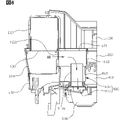
車両用空調装置の二層流送風装置は、図3及び4に図示されたように、上部送風ケース100、下部送風ケース200、インテークボックス300、排水ケース400、モータケース500、送風ファン600、送風モータ700及び送風モータ冷却ユニット800を含んでなる。
As shown in FIGS. 3 and 4, the two-layer flow blower for a vehicle air conditioner includes an
一対の上部送風ケース100及び下部送風ケース200は図3及び4に図示されたように上部に形成された空気流入口101から吸入された内外気が側方向に形成された一対の上部送風ダクト110及び下部送風ダクト120にそれぞれ送風されるようにスクロール形状を有し、区画板150を通じて上下に区画される。即ち、上方の上部送風ケース100と下方の下部送風ケース200が中間の区画板150を基準に上下に分離されて結合される。
As shown in FIGS. 3 and 4, the pair of
この時、上部送風ケース100の側方向に形成された上部送風ダクト110と下部送風ケース200の側方向に形成された下部送風ダクト210にそれぞれ内外気が分離されて送風される。上部送風ダクト110及び下部送風ダクト210によって二層流を形成するようになり、このように二層流が形成されて送風された内外気は図1を参照すると空調ユニットを経て冷気又は温気に変換されて車両の内部に排出される。車両の二層流空調機用空調ユニットは図1に図示された単層流空調機用空調ユニットより複雑な構成を有しており、広く知られているのでその詳細な説明は省略する。
At this time, the internal and external air is separated and blown to the
インテークボックス300は図3に図示されたように上部送風ケース100の上部に結合され、空気流入口101を選択的に開閉する。即ち、インテークボックス300は上部送風ケース100の上部に形成された空気流入口101の上に結合され、内気又は外気や内外気が共に空気流入口101に吸入されるように制御し、インテークボックス300もやはり内外気の吸入制御のための多様な構造を有するのでその詳細な説明は省略する。
The
排水ケース400は図3及び4に図示されたように下部送風ケース200の下部に結合され、下部送風ダクト210の長手方向に沿って下方に向かって傾斜するように排水ダクト410が形成される。このような排水ケース400は空気流入口101から流入された内外気に含まれた水を排水ダクト410を通じて排水するための構成である。
As shown in FIGS. 3 and 4, the
即ち、空気流入口101に流入された内外気は後述する送風ファン600によって回転しながら上部送風ダクト110及び下部送風ダクト210に強制送風される。この時、内外気に含まれた水は送風ファン600の回転による遠心力によって上部送風ケース100及び下部送風ケース200の内側壁に沿って流れ落ちるようになり、このように流れ落ちた水は排水ケース400に集まった後に排水ダクト410を通じて排水される。特に、排水ケース400の排水ダクト410は後述する送風モータ冷却ユニット800の冷却チャンバ810に貯水される水を排水するための機能も共に行われるようになる。
That is, the inside and outside air introduced into the
モータケース500は図3及び4に図示されたように排水ケース400の下部に結合される。このようなモータケース500は名称通り後述する送風モータ700が内部に設置されて外部から送風モータ700を保護するための構成である。
送風ファン600は図4及び5に図示されたように上部送風ケース100及び下部送風ケース200の内部に設置されて内外気を吸入した後に上部送風ダクト110及び下部送風ダクト210のそれぞれに向かって送風する。即ち、インテークボックス300を通じて内気又は外気の吸入を制御して空気流入口101に内外気が吸入される時、送風ファン600の回転によって吸入された内外気を強制的に上部送風ダクト110及び下部送風ダクト210のそれぞれに向かって送風するようになる。この時、送風ファン600は両方向吸入式遠心型多翼ファンであって、中央のハブ及び周りの翼部を含み、上下に区画される二層流の形成のために上下に翼部が分かれて吸入された内外気を分離して上部送風ダクト110及び下部送風ダクト210のそれぞれに向かって送風するようになるものである。
As shown in FIGS. 4 and 5, the blowing
送風モータ700は図4及び5に図示されたようにモータケース500の内部に設置され、送風ファン600を回転させる。送風モータ700は電源の印加によって回転する電気モータであって、特にパワー冷房や暖房時に負荷が上昇するようになると高熱が発生するようになるのでこのような送風モータ700の熱を冷却させる必要がある。このために送風モータ冷却ユニット800が設置されるものである。
The
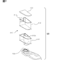
送風モータ冷却ユニット800は図3乃至8に図示されたように下部送風ダクト210から送風される空気(AR)の一部を分岐して冷却チャンバ810の内部に流入させた後にモータケース500の内部に循環させて送風モータ700を冷却する。車両用空調装置の二層流送風装置における送風モータ冷却ユニット800は冷却チャンバ810及びモータ冷却流路820を含む。
As shown in FIGS. 3 to 8, the blower
まず、冷却チャンバ810はチャンバ上板811と共に2個の層で構成される上部チャンバ812及び下部チャンバ813を含む。チャンバ上板811は冷却チャンバ810の天井に該当し、上部送風ケース100から連結される上部送風ダクト110の一側に延長形成される。上部チャンバ812は下部送風ケース200から連結される下部送風ダクト210の一側に延長形成されるように上下開放され、開放された上部はチャンバ上板811によって密閉され、下部送風ダクト210から送風される空気の一部を分岐して流入させるように冷却流入ホール812aが貫通形成される。下部チャンバ813は排水ケース400の一側に延長形成されるように上部が開放され、開放された上部は上部チャンバ812の下部と連通されるように結合され、内部に下面を貫通して上下に直立する冷却チューブ813aが形成されてモータケース500の内部と連通する。
First, the cooling
したがって、空気流入口101に吸入された内外気は送風ファン600の回転によって上部送風ダクト110及び下部送風ダクト210のそれぞれに向かって送風され、下部送風ダクト210に向かって送風される空気のうち一部が分岐して上部チャンバ812の冷却流入ホール812aを通じて上部チャンバ812の内部に流入される。このように冷却流入ホール812aを通じて流入された空気は下部チャンバ813の冷却チューブ813aを経由してモータケース500の内部に循環され、モータケース500の内部に設置された送風モータ700を冷却させた後に再び送風ファン600の回転によって下部送風ダクト210に向かって送風されるようになる。
Therefore, the inside/outside air sucked into the
冷却流入ホール812aを通じて流入された空気が冷却チューブ813aを経由してモータケース500の内部に循環されるために、モータ冷却流路820がモータケース500に形成される。即ち、モータ冷却流路820は一側がモータケース500の内部と連通されるように延長形成され、他側が下部チャンバ813の冷却チューブ813aの下端と連通されるように結合される。したがって、冷却流入ホール812aを通じて流入された空気は冷却チャンバ810の内部に流入された後に冷却チューブ813aを経由してモータ冷却流路820を通じてモータケース500の内部に循環されるものである。
A
冷却チャンバ810を上部チャンバ812及び下部チャンバ813で構成した理由は、第1に下部チャンバ813に一定の高さを有した冷却チューブ813aを形成して冷却流入ホール812aを通じて流入された空気中に含まれた水が冷却チャンバ810の内部に貯水されても十分な時間を確保するためのものであり、第2に冷却チューブ813aの高さが確保された分だけ上部チャンバ812に形成された冷却流入ホール812aの高さもやはり冷却チューブ813aの高さより高く形成されなければモータケース500への空気循環が円滑になされないためである。
The reason why the
即ち、下部チャンバ813に冷却チューブ813aが直立して形成されていることにより、冷却流入ホール812aを通じて流入された空気中に含まれた水が下部チャンバ813の内部の底に少しずつ貯水されても冷却チューブ813aの高さまで一度に満ちず、徐々に密閉された結合面に沿って排水されたり蒸発されたりして消える時間を確保することができるものである。
That is, since the
車両用空調装置の二層流送風装置における送風モータ冷却ユニット800の第1実施例の構造だけでも十分に送風モータ700の冷却及び水侵入防止効果をもたらすことができる。しかしながら、雨天時のように持続的な水の流入が多量に発生する場合における車両運転時には図9に図示されたように冷却チャンバ810の内部に貯水される水(WT)が冷却チューブ813aの高さを超えてモータ冷却流路820を通じてモータケース500の内部に流れることができる。水(WT)は、水の塊、水滴、霧など多様な態様で存在する場合がある。この時、多量の水がモータケース500の内部に突然流れて満ちるようになると送風モータ700が停止したり短絡に繋がる安全事故が発生したりする恐れがある。
The structure of the blower
このような特殊な状況下における問題まで解決するために図10乃至18に図示されたように車両用空調装置の二層流送風装置における送風モータ冷却ユニット800の第2実施例乃至第5実施例を分けて見る。
In order to solve the problem under such a special situation, as shown in FIGS. 10 to 18, the second to fifth embodiments of the fan
まず、図10及び11に図示されたように送風モータ冷却ユニット800の第2実施例は、前述した第1実施例と同一の構成で上部チャンバ812の構造変化を通じて問題点を解決した。即ち、上部チャンバ812は下面を密閉する第1下面遮断板812bが形成され、第1下面遮断板812bには冷却チューブ813aの上端が貫通挿入されるように第1冷却チューブ挿入ホール812baが貫通形成され、第1下面遮断板812bの上部に貯水される水を下部送風ダクト210に排出するように冷却流入ホール812aの下方に第1排水ホール812c又は第1排水スリット812dが貫通形成される。
First, as shown in FIGS. 10 and 11, the second embodiment of the blower
したがって、上部チャンバ812の冷却流入ホール812aを通じて流入された空気は冷却チューブ813aを経由してモータ冷却流路820を通じてモータケース500の内部に循環し、上部チャンバ812の第1下面遮断板812bの上部に水が貯水されても第1排水ホール812c又は第1排水スリット812dを通じて下部送風ダクト210に排出されるようになるので冷却チャンバ810の内部には水が貯水される恐れがないものである。
Therefore, the air introduced through the cooling
もっとも、この場合、上部チャンバ812の底面と冷却チューブ813aの上端の高さまでの差が小さいので傾斜した道路における車両の動きによって誤って冷却チューブ813aに流れ込む恐れがあり、第1排水ホール812c又は第1排水スリット812dを通じて下部送風ダクト210から空気が流入されて排水が円滑ではない可能性がある。これを解決するために、図12及び13に図示されたように送風モータ冷却ユニット800の第3実施例を提示する。
However, in this case, since the height difference between the bottom surface of the
即ち、図12及び13に図示されたように送風モータ冷却ユニット800の第3実施例は、前述した第1実施例と同一の構成で下部チャンバ813の構造変化を通じて問題点まで解決した。下部チャンバ812は下面の上部に貯水される水を排水ダクト410に排出するように排水ダクト410を見る側面に第2排水ホール813b又は第2排水スリット813cが貫通形成される。この時、下部チャンバ813の冷却チューブ813aは上端の高さが少なくとも第2排水ホール813b又は第2排水スリット813cの上端の高さより高く形成されなければならない。
That is, as shown in FIGS. 12 and 13, the third embodiment of the blower
したがって、上部チャンバ812の冷却流入ホール812aを通じて流入された空気は冷却チューブ813aを経由してモータ冷却流路820を通じてモータケース500の内部に循環し、下部チャンバ813の底に水が貯水されても第2排水ホール813b又は第2排水スリット813cを通じて排水ダクト410に排出されるようになるので冷却チャンバ810の内部には水が貯水される恐れがないものである。
Therefore, the air introduced through the cooling
さらに、送風モータ冷却ユニット800の第3実施例は冷却チューブ813aの上端の高さを十分に高く形成することができるので傾斜した道路における車両の動きにも冷却チューブ813aに水が流れ込む恐れがなく、下部送風ダクト210から流入される空気は専ら冷却流入ホール812aだけを通じてなされるので送風モータ700の冷却のための空気の循環もやはり円滑な効果がある。
Furthermore, the third embodiment of the blower
一方、送風モータ冷却ユニット800の第3実施例をより拡張した第4実施例を図14乃至16を参照して見る。即ち、下部チャンバ813は下面の上部に貯水される水を排水ダクト410に排出するように排水ダクト410を見る側面を開口させる。この時、下部チャンバ813の冷却チューブ813aは上端の高さが下部チャンバ813の上端の高さより高く形成されなければならない。
On the other hand, a fourth embodiment, which is a more extended version of the third embodiment of the blower
このような送風モータ冷却ユニット800の第4実施例は第3実施例と比較して側面を完全に開口させたものである。もっとも、第4実施例の場合は冷却チャンバ810の内部に水が貯水されることは確実に解決することができるが、冷却流入ホール812aを通じて流入された空気もやはり排水ダクト410に容易に抜け出るようになって送風モータ700の冷却効率が落ちる恐れがある。これを解決するために、図17及び18に図示されたように送風モータ冷却ユニット800の第5実施例を提示する。
The fourth embodiment of such fan
即ち、図17及び18に図示されたように送風モータ冷却ユニット800の第5実施例は、前述した第4実施例と同一の構成で上部チャンバ812の構造変化を通じて問題点まで解決した。上部チャンバ812は下面を密閉する第2下面遮断板812eが形成され、第2下面遮断板812eには冷却チューブ813aの上端が貫通挿入されるように第2冷却チューブ挿入ホール812eaが貫通形成され、第2下面遮断板812eの上部に貯水される水を下方に向かって排出するように第2下面遮断板812eに第3排水ホール812eb又は第3排水スリット812ecが上下に貫通形成される。
That is, as shown in FIGS. 17 and 18, the blower
したがって、上部チャンバ812の冷却流入ホール812aを通じて流入された空気は冷却チューブ813aを経由してモータ冷却流路820を通じてモータケース500の内部に循環し、上部チャンバ812の第2下面遮断板812eに水が貯水されても第3排水ホール812eb又は第3排水スリット812ecを通じて下方に排出されるようになる。この時、第2下面遮断板812eの下方には下部チャンバ813があり、第2下面遮断板812eの第3排水ホール812eb又は第3排水スリット812ecを通じて下方に排出された水は下部チャンバ813の開口された側面を通じて排水ダクト410に排出されるようになるので冷却チャンバ810の内部には水が貯水される恐れがないものである。
Therefore, the air introduced through the cooling
さらに、送風モータ冷却ユニット800の第5実施例は第2下面遮断板812eに水が貯水されず、常に第3排水ホール812eb又は第3排水スリット812ecを通じて下方に排出されるので傾斜した道路における車両の動きにも冷却チューブ813aに水が流れ込む恐れがなく、下部送風ダクト210から流入される空気もやはり第2下面遮断板812eによって遮られて殆どが冷却チューブ813aに流れながら送風モータ700の冷却のための空気の循環もやはり円滑な効果がある。
Furthermore, in the fifth embodiment of the blower
車両用空調装置の二層流送風装置は、二層流を形成する空調機用送風装置に適合するように送風モータ700を冷却するための新たな冷却構造を有する送風モータ冷却ユニット800を提供する。特に送風モータ冷却ユニット800の冷却チャンバ810の構造をチャンバ上板811、上部チャンバ812及び下部チャンバ813で構成しながら冷却流入ホール812aと冷却チューブ813aによる第1乃至第3排水ホール又は排水スリットを通じて送風モータ700に多量の水が侵入することを防止することができる効果がある。
A two-layer flow blower for vehicle air conditioner provides a blower
複数の実施例は、開示された技術的思想を限定するものと解釈されてはならない。開示の保護範囲は請求の範囲に記載された事項のみによって制限され、開示の技術分野で通常の知識を有した者は技術的思想を多様な形態に改良変更することが可能である。したがって、このような改良及び変更は通常の知識を有した者に自明なものである限り、開示の保護範囲に属するようになるはずである。 The multiple embodiments should not be construed as limiting the disclosed technical ideas. The scope of protection of the disclosure is limited only by the matters described in the claims, and those who have ordinary knowledge in the technical field of the disclosure can improve and change the technical idea into various forms. Therefore, such improvements and modifications should fall within the protection scope of the disclosure as long as they are obvious to those of ordinary skill in the art.
Claims (2)
前記空気流入口を選択的に開閉するように前記上部送風ケースの上部に結合されたインテークボックス(300)と、
前記下部送風ケースの下部に結合され、前記下部送風ダクトの長手方向に沿って下方に向かって傾斜するように排水ダクトが形成された排水ケース(400)と、
前記排水ケースの下部に結合されたモータケース(500)と、
前記上部送風ケース及び下部送風ケースの内部に設置されて内外気を吸入した後に前記上部送風ダクト及び下部送風ダクトのそれぞれに向かって送風する送風ファン(600)と、
前記モータケースの内部に設置され、前記送風ファンを回転させる送風モータ(700)と、
前記下部送風ダクトから送風される空気の一部を分岐して冷却チャンバの内部に流入させた後に前記モータケースの内部に循環させて前記送風モータを冷却する送風モータ冷却ユニット(800)を備え、
前記送風モータ冷却ユニットの冷却チャンバは、
前記上部送風ケースから連結される前記上部送風ダクトの一側に延長形成されたチャンバ上板(811)と、
前記下部送風ケースから連結される前記下部送風ダクトの一側に延長形成されるように上下開放され、開放された上部は前記チャンバ上板によって密閉され、前記下部送風ダクトから送風される空気の一部を分岐して流入させるように冷却流入ホールが貫通形成された上部チャンバ(812)と、
前記排水ケースから連結される前記排水ダクトの一側に延長形成されるように上部が開放され、開放された上部は前記上部チャンバの下部と連通されるように結合され、内部に下面を貫通して上下に直立する冷却チューブが形成されて前記モータケースの内部と連通する下部チャンバ(813)を含み、
前記上部チャンバは、
下面を密閉する第1下面遮断板が形成され、前記第1下面遮断板には前記冷却チューブの上端が貫通挿入されるように第1冷却チューブ挿入ホール(812ba)が貫通形成され、
前記第1下面遮断板の上部に貯水される水を前記下部送風ダクトに排出するように前記冷却流入ホールの下方に第1排水ホール(812c)又は第1排水スリット(812d)が貫通形成されている車両用空調装置の二層流送風装置。 It has a scroll shape so that the inside and outside air sucked from the air inlet formed in the upper part is blown into a pair of upper and lower air ducts formed in the side direction, and is divided vertically through the partition plate. a pair of upper blower case (100) and lower blower case (200);
an intake box (300) coupled to the upper portion of the upper blower case to selectively open and close the air inlet;
a drainage case (400) coupled to the lower portion of the lower blower case and formed with a drain duct inclined downward along the longitudinal direction of the lower blower duct;
a motor case (500) coupled to the bottom of the drainage case;
a blower fan (600) installed inside the upper blower case and the lower blower case, sucking inside and outside air and blowing air toward the upper blower duct and the lower blower duct, respectively;
a blower motor (700) installed inside the motor case to rotate the blower fan;
a blower motor cooling unit (800) for cooling the blower motor by branching a part of the air blown from the lower blower duct and flowing it into the cooling chamber and then circulating it inside the motor case ;
The cooling chamber of the blower motor cooling unit comprises:
a chamber top plate (811) extending from one side of the upper fan duct connected to the upper fan case;
The upper and lower parts are opened so as to extend to one side of the lower fan duct connected to the lower fan case. an upper chamber (812) through which a cooling inlet hole is formed to diverge and enter the part;
The upper part is opened so as to extend to one side of the drainage duct connected to the drainage case, and the opened upper part is connected to the lower part of the upper chamber so as to communicate with the lower part of the upper chamber and penetrates the lower surface thereof. a lower chamber (813) formed with vertically upright cooling tubes communicating with the interior of the motor case;
The upper chamber is
A first lower shielding plate is formed to seal the lower surface, and a first cooling tube insertion hole (812ba) is formed through the first lower shielding plate so that the upper end of the cooling tube is inserted therethrough,
A first drainage hole (812c) or a first drainage slit (812d) is formed below the cooling inflow hole so as to discharge the water stored above the first bottom blocking plate to the lower air duct. two-layer flow blower for vehicle air conditioners.
前記空気流入口を選択的に開閉するように前記上部送風ケースの上部に結合されたインテークボックス(300)と、
前記下部送風ケースの下部に結合され、前記下部送風ダクトの長手方向に沿って下方に向かって傾斜するように排水ダクトが形成された排水ケース(400)と、
前記排水ケースの下部に結合されたモータケース(500)と、
前記上部送風ケース及び下部送風ケースの内部に設置されて内外気を吸入した後に前記上部送風ダクト及び下部送風ダクトのそれぞれに向かって送風する送風ファン(600)と、
前記モータケースの内部に設置され、前記送風ファンを回転させる送風モータ(700)と、
前記下部送風ダクトから送風される空気の一部を分岐して冷却チャンバの内部に流入させた後に前記モータケースの内部に循環させて前記送風モータを冷却する送風モータ冷却ユニット(800)を備え、
前記送風モータ冷却ユニットの冷却チャンバは、
前記上部送風ケースから連結される前記上部送風ダクトの一側に延長形成されたチャンバ上板(811)と、
前記下部送風ケースから連結される前記下部送風ダクトの一側に延長形成されるように上下開放され、開放された上部は前記チャンバ上板によって密閉され、前記下部送風ダクトから送風される空気の一部を分岐して流入させるように冷却流入ホールが貫通形成された上部チャンバ(812)と、
前記排水ケースから連結される前記排水ダクトの一側に延長形成されるように上部が開放され、開放された上部は前記上部チャンバの下部と連通されるように結合され、内部に下面を貫通して上下に直立する冷却チューブが形成されて前記モータケースの内部と連通する下部チャンバ(813)を含み、
前記下部チャンバは、
下面の上部に貯水される水を前記排水ダクトに排出するように前記排水ダクトを見る側面を開口させ、
前記下部チャンバの冷却チューブは、
上端の高さが前記下部チャンバの上端の高さより高く形成されており、
前記上部チャンバは、
下面を密閉する第2下面遮断板が形成され、前記第2下面遮断板には前記冷却チューブの上端が貫通挿入されるように第2冷却チューブ挿入ホール(812ea)が貫通形成され、
前記第2下面遮断板の上部に貯水される水を下方に向かって排出するように前記第2下面遮断板に第3排水ホール(812eb)又は第3排水スリット(812ec)が上下に貫通形成されている車両用空調装置の二層流送風装置。 It has a scroll shape so that the inside and outside air sucked from the air inlet formed in the upper part is blown into a pair of upper and lower air ducts formed in the side direction, and is divided vertically through the partition plate. a pair of upper blower case (100) and lower blower case (200);
an intake box (300) coupled to the upper portion of the upper blower case to selectively open and close the air inlet;
a drainage case (400) coupled to the lower portion of the lower blower case and formed with a drain duct inclined downward along the longitudinal direction of the lower blower duct;
a motor case (500) coupled to the bottom of the drainage case;
a blower fan (600) installed inside the upper blower case and the lower blower case, sucking inside and outside air and blowing air toward the upper blower duct and the lower blower duct, respectively;
a blower motor (700) installed inside the motor case to rotate the blower fan;
a blower motor cooling unit (800) for cooling the blower motor by branching a part of the air blown from the lower blower duct and flowing it into the cooling chamber and then circulating it inside the motor case ;
The cooling chamber of the blower motor cooling unit comprises:
a chamber top plate (811) extending from one side of the upper fan duct connected to the upper fan case;
The upper and lower parts are opened so as to extend to one side of the lower fan duct connected to the lower fan case. an upper chamber (812) through which a cooling inlet hole is formed to diverge and enter the part;
The upper part is opened so as to extend to one side of the drainage duct connected to the drainage case, and the opened upper part is connected to the lower part of the upper chamber so as to communicate with the lower part of the upper chamber and penetrates the lower surface thereof. a lower chamber (813) formed with vertically upright cooling tubes communicating with the interior of the motor case;
The lower chamber is
The side of the drainage duct is opened so that the water stored in the upper part of the lower surface is discharged to the drainage duct,
the cooling tube of the lower chamber,
The height of the upper end is formed higher than the height of the upper end of the lower chamber,
The upper chamber is
A second lower shielding plate is formed to seal the lower surface, and a second cooling tube insertion hole (812ea) is formed through the second lower shielding plate so that the upper end of the cooling tube is inserted therethrough,
A third drain hole (812eb) or a third drain slit (812ec) is formed vertically through the second lower blocking plate so as to discharge water stored in the upper part of the second lower blocking plate downward. Two-layer flow blower for vehicle air conditioners.
Applications Claiming Priority (3)
| Application Number | Priority Date | Filing Date | Title |
|---|---|---|---|
| KR10-2019-0150089 | 2019-11-21 | ||
| KR1020190150089A KR102292952B1 (en) | 2019-11-21 | 2019-11-21 | Blowing apparatus of air conditioner for vehicle with two layer air flow |
| PCT/JP2020/042467 WO2021100629A1 (en) | 2019-11-21 | 2020-11-13 | Two-layer-flow air blowing device for vehicle air conditioner |
Publications (3)
| Publication Number | Publication Date |
|---|---|
| JPWO2021100629A1 JPWO2021100629A1 (en) | 2021-05-27 |
| JPWO2021100629A5 JPWO2021100629A5 (en) | 2022-01-28 |
| JP7156552B2 true JP7156552B2 (en) | 2022-10-19 |
Family
ID=75981251
Family Applications (1)
| Application Number | Title | Priority Date | Filing Date |
|---|---|---|---|
| JP2021558352A Active JP7156552B2 (en) | 2019-11-21 | 2020-11-13 | Two-layer flow blower for vehicle air conditioner |
Country Status (4)
| Country | Link |
|---|---|
| US (1) | US20220274459A1 (en) |
| JP (1) | JP7156552B2 (en) |
| KR (1) | KR102292952B1 (en) |
| WO (1) | WO2021100629A1 (en) |
Citations (4)
| Publication number | Priority date | Publication date | Assignee | Title |
|---|---|---|---|---|
| JP2004231146A (en) | 2003-02-03 | 2004-08-19 | Denso Corp | Vehicle air conditioner |
| JP2017171020A (en) | 2016-03-22 | 2017-09-28 | 株式会社日本クライメイトシステムズ | Ventilator for vehicle air conditioning |
| JP2018167628A (en) | 2017-03-29 | 2018-11-01 | 株式会社日本クライメイトシステムズ | Ventilator for vehicle air conditioning |
| JP2019171980A (en) | 2018-03-27 | 2019-10-10 | 株式会社日本クライメイトシステムズ | Air blower for vehicle air conditioning |
Family Cites Families (11)
| Publication number | Priority date | Publication date | Assignee | Title |
|---|---|---|---|---|
| JP3269467B2 (en) * | 1998-10-28 | 2002-03-25 | 株式会社デンソー | Vehicle air conditioner |
| KR100917579B1 (en) * | 2003-02-26 | 2009-09-15 | 한라공조주식회사 | Drainage Structure of HVAC |
| US7118355B2 (en) * | 2005-02-04 | 2006-10-10 | Delphi Technologies, Inc. | Electric motor driven blower assembly with integral motor cooling duct |
| US20080115518A1 (en) * | 2005-08-03 | 2008-05-22 | Calsonic Kansei Corporation | Vehicular Air Conditioner |
| JP4396738B2 (en) * | 2007-07-23 | 2010-01-13 | 株式会社デンソー | Air conditioner |
| KR102512337B1 (en) * | 2016-01-06 | 2023-03-23 | 한온시스템 주식회사 | Blower unit of air conditioner for vehicle |
| JP6260838B2 (en) * | 2016-02-29 | 2018-01-17 | 株式会社ケーヒン | Blower motor unit for air conditioning |
| JP6873622B2 (en) * | 2016-07-15 | 2021-05-19 | 三菱重工サーマルシステムズ株式会社 | Blower, air conditioner for vehicles |
| JP6562156B2 (en) * | 2016-08-29 | 2019-08-21 | 株式会社デンソー | Blower unit |
| JP6925910B2 (en) * | 2017-08-25 | 2021-08-25 | 株式会社ヴァレオジャパン | Centrifugal blower for vehicle air conditioners |
| JP7195061B2 (en) * | 2018-06-12 | 2022-12-23 | 株式会社日本クライメイトシステムズ | Air blower for vehicle air conditioning |
-
2019
- 2019-11-21 KR KR1020190150089A patent/KR102292952B1/en not_active Expired - Fee Related
-
2020
- 2020-11-13 JP JP2021558352A patent/JP7156552B2/en active Active
- 2020-11-13 WO PCT/JP2020/042467 patent/WO2021100629A1/en not_active Ceased
-
2022
- 2022-05-18 US US17/747,620 patent/US20220274459A1/en not_active Abandoned
Patent Citations (4)
| Publication number | Priority date | Publication date | Assignee | Title |
|---|---|---|---|---|
| JP2004231146A (en) | 2003-02-03 | 2004-08-19 | Denso Corp | Vehicle air conditioner |
| JP2017171020A (en) | 2016-03-22 | 2017-09-28 | 株式会社日本クライメイトシステムズ | Ventilator for vehicle air conditioning |
| JP2018167628A (en) | 2017-03-29 | 2018-11-01 | 株式会社日本クライメイトシステムズ | Ventilator for vehicle air conditioning |
| JP2019171980A (en) | 2018-03-27 | 2019-10-10 | 株式会社日本クライメイトシステムズ | Air blower for vehicle air conditioning |
Also Published As
| Publication number | Publication date |
|---|---|
| KR102292952B1 (en) | 2021-08-23 |
| JPWO2021100629A1 (en) | 2021-05-27 |
| US20220274459A1 (en) | 2022-09-01 |
| WO2021100629A1 (en) | 2021-05-27 |
| KR20210062190A (en) | 2021-05-31 |
Similar Documents
| Publication | Publication Date | Title |
|---|---|---|
| CN108698482B (en) | Air conditioning unit for vehicle | |
| JP4811385B2 (en) | Air conditioner for vehicles | |
| JP5772709B2 (en) | Air conditioner for vehicles | |
| EP3524452A1 (en) | Air conditioning unit for vehicle | |
| WO1999007568A1 (en) | Air conditioner for vehicles | |
| US20180022192A1 (en) | Air-conditioning unit for vehicle | |
| JP6406442B2 (en) | Air conditioning unit for vehicles | |
| JP5353665B2 (en) | Air conditioner for vehicles | |
| JP7156552B2 (en) | Two-layer flow blower for vehicle air conditioner | |
| KR20170072987A (en) | Air conditioner for vehicle | |
| JP7061842B2 (en) | Blower for vehicle air conditioning | |
| JPWO2018123111A1 (en) | Air conditioner | |
| JP2019006160A (en) | Blower for vehicle | |
| JP6540888B2 (en) | Vehicle air conditioning unit | |
| KR102512337B1 (en) | Blower unit of air conditioner for vehicle | |
| JP4482881B2 (en) | Air conditioning unit for vehicles | |
| JP4034049B2 (en) | Air conditioner for vehicles | |
| KR102027763B1 (en) | An intake device for air conditioner of vehicles | |
| JP4467128B2 (en) | Unit drainage structure for vehicle air conditioners | |
| JP2009220761A (en) | Air-conditioner | |
| JP2007090923A (en) | Air conditioning unit for vehicle | |
| KR20240169803A (en) | Air conditioner for vehicle | |
| JPH10244821A (en) | Car air conditioning device | |
| KR100922425B1 (en) | Air conditioning unit with low air flow resistance | |
| JP2009208748A (en) | Vehicular air-conditioner |
Legal Events
| Date | Code | Title | Description |
|---|---|---|---|
| A521 | Request for written amendment filed |
Free format text: JAPANESE INTERMEDIATE CODE: A523 Effective date: 20211025 |
|
| A621 | Written request for application examination |
Free format text: JAPANESE INTERMEDIATE CODE: A621 Effective date: 20211025 |
|
| TRDD | Decision of grant or rejection written | ||
| A01 | Written decision to grant a patent or to grant a registration (utility model) |
Free format text: JAPANESE INTERMEDIATE CODE: A01 Effective date: 20220906 |
|
| A61 | First payment of annual fees (during grant procedure) |
Free format text: JAPANESE INTERMEDIATE CODE: A61 Effective date: 20220919 |
|
| R151 | Written notification of patent or utility model registration |
Ref document number: 7156552 Country of ref document: JP Free format text: JAPANESE INTERMEDIATE CODE: R151 |
|
| R250 | Receipt of annual fees |
Free format text: JAPANESE INTERMEDIATE CODE: R250 |