JP7154751B2 - game machine - Google Patents
game machine Download PDFInfo
- Publication number
- JP7154751B2 JP7154751B2 JP2017226401A JP2017226401A JP7154751B2 JP 7154751 B2 JP7154751 B2 JP 7154751B2 JP 2017226401 A JP2017226401 A JP 2017226401A JP 2017226401 A JP2017226401 A JP 2017226401A JP 7154751 B2 JP7154751 B2 JP 7154751B2
- Authority
- JP
- Japan
- Prior art keywords
- notification
- advantageous section
- advantageous
- game
- lamp
- Prior art date
- Legal status (The legal status is an assumption and is not a legal conclusion. Google has not performed a legal analysis and makes no representation as to the accuracy of the status listed.)
- Active
Links
- 230000007704 transition Effects 0.000 claims description 135
- 230000000694 effects Effects 0.000 claims description 71
- 238000009795 derivation Methods 0.000 claims description 51
- 230000003213 activating effect Effects 0.000 claims description 2
- 241000167854 Bourreria succulenta Species 0.000 description 199
- 235000019693 cherries Nutrition 0.000 description 199
- 238000000034 method Methods 0.000 description 104
- 238000012545 processing Methods 0.000 description 103
- 230000008569 process Effects 0.000 description 80
- 239000004973 liquid crystal related substance Substances 0.000 description 47
- 238000010586 diagram Methods 0.000 description 46
- 230000001276 controlling effect Effects 0.000 description 42
- 230000008859 change Effects 0.000 description 21
- 230000008901 benefit Effects 0.000 description 20
- 230000006870 function Effects 0.000 description 19
- 238000003825 pressing Methods 0.000 description 19
- 238000012986 modification Methods 0.000 description 17
- 230000004048 modification Effects 0.000 description 17
- 238000012790 confirmation Methods 0.000 description 15
- 238000004519 manufacturing process Methods 0.000 description 15
- YAFQFNOUYXZVPZ-UHFFFAOYSA-N liproxstatin-1 Chemical compound ClC1=CC=CC(CNC=2C3(CCNCC3)NC3=CC=CC=C3N=2)=C1 YAFQFNOUYXZVPZ-UHFFFAOYSA-N 0.000 description 14
- 230000008014 freezing Effects 0.000 description 13
- 238000007710 freezing Methods 0.000 description 13
- 230000001976 improved effect Effects 0.000 description 9
- 238000003860 storage Methods 0.000 description 9
- 238000001514 detection method Methods 0.000 description 7
- 230000004044 response Effects 0.000 description 7
- 230000004397 blinking Effects 0.000 description 6
- 241000219109 Citrullus Species 0.000 description 5
- 235000012828 Citrullus lanatus var citroides Nutrition 0.000 description 5
- 230000001174 ascending effect Effects 0.000 description 5
- 230000007423 decrease Effects 0.000 description 5
- 238000013461 design Methods 0.000 description 5
- 239000002243 precursor Substances 0.000 description 5
- 238000012360 testing method Methods 0.000 description 5
- 239000003086 colorant Substances 0.000 description 4
- 230000001960 triggered effect Effects 0.000 description 4
- 230000004913 activation Effects 0.000 description 3
- 230000003111 delayed effect Effects 0.000 description 3
- 230000002349 favourable effect Effects 0.000 description 3
- 230000007257 malfunction Effects 0.000 description 3
- 238000011084 recovery Methods 0.000 description 3
- 230000000630 rising effect Effects 0.000 description 3
- 238000012546 transfer Methods 0.000 description 3
- 238000010200 validation analysis Methods 0.000 description 3
- 230000005856 abnormality Effects 0.000 description 2
- 238000004364 calculation method Methods 0.000 description 2
- 230000000052 comparative effect Effects 0.000 description 2
- 230000006872 improvement Effects 0.000 description 2
- 238000012423 maintenance Methods 0.000 description 2
- 238000012544 monitoring process Methods 0.000 description 2
- 230000002250 progressing effect Effects 0.000 description 2
- 239000000758 substrate Substances 0.000 description 2
- 101000971351 Homo sapiens KRR1 small subunit processome component homolog Proteins 0.000 description 1
- 102100021559 KRR1 small subunit processome component homolog Human genes 0.000 description 1
- OMFRMAHOUUJSGP-IRHGGOMRSA-N bifenthrin Chemical compound C1=CC=C(C=2C=CC=CC=2)C(C)=C1COC(=O)[C@@H]1[C@H](\C=C(/Cl)C(F)(F)F)C1(C)C OMFRMAHOUUJSGP-IRHGGOMRSA-N 0.000 description 1
- 230000002844 continuous effect Effects 0.000 description 1
- 239000013256 coordination polymer Substances 0.000 description 1
- 238000011161 development Methods 0.000 description 1
- 238000003780 insertion Methods 0.000 description 1
- 230000037431 insertion Effects 0.000 description 1
- 230000009467 reduction Effects 0.000 description 1
- 230000000717 retained effect Effects 0.000 description 1
- 239000013589 supplement Substances 0.000 description 1
Images


Landscapes
- Slot Machines And Peripheral Devices (AREA)
- Game Rules And Presentations Of Slot Machines (AREA)
Description
本発明は、各々が識別可能な複数種類の識別情報を変動表示可能な可変表示部を備え、
前記可変表示部を変動表示した後、前記可変表示部の変動表示を停止することで表示結果
を導出し、該表示結果に応じて入賞が発生可能なスロットマシン等の遊技機に関する。
The present invention comprises a variable display unit capable of variably displaying a plurality of types of identification information that are each identifiable,
The present invention relates to a game machine, such as a slot machine, in which a display result is derived by stopping the variable display of the variable display portion after the variable display portion is variably displayed, and winning can occur according to the display result.
従来から、遊技機として、リールを停止させるためのストップスイッチの操作態様を報
知不可能な通常区間と、当該操作態様を報知可能な有利区間とのいずれかに制御可能であ
って、有利区間に制御されていることをセグメントの点灯によって示唆するスロットマシ
ンがあった(たとえば、特許文献1)。
Conventionally, as a game machine, it is possible to control either a normal section in which the operation mode of the stop switch for stopping the reel cannot be notified, or an advantageous section in which the operation mode can be notified. There is a slot machine that indicates that it is being controlled by lighting a segment (for example, Patent Document 1).
上述したスロットマシンでは、操作態様を報知している状況で電断が発生し該電断から
復帰したときにおいて、操作態様の報知が再開される前にストップスイッチへの操作が有
効となると、報知される操作態様とは異なる操作態様つまり誤った操作態様で遊技者がス
トップスイッチを操作してしまう虞があった。
In the slot machine described above, when a power failure occurs while the operation mode is being notified and the power is restored from the power failure, it is notified that the operation of the stop switch becomes effective before the operation mode notification is resumed. There is a risk that the player will operate the stop switch in an operation mode different from the operation mode that is used, that is, in an erroneous operation mode.
この発明は、かかる実情に鑑み考え出されたものであり、その目的は、誤った操作態様
で遊技者が導出操作手段を操作することを防止するスロットマシンを提供することである
。
SUMMARY OF THE INVENTION The present invention has been conceived in view of such circumstances, and its object is to provide a slot machine that prevents a player from operating a lead-out operation means in an erroneous operation mode.
(A) 各々が識別可能な複数種類の識別情報を変動表示可能な可変表示部を備え、
前記可変表示部を変動表示した後、前記可変表示部の変動表示を停止することで表示結果を導出するスロットマシンにおいて、
表示結果を導出させるために操作される導出操作手段と、
通常区間よりも有利な有利区間に移行させる有利区間移行手段と、
遊技者にとって有利な有利操作態様を報知する有利状態に、前記有利区間であるときに制御する有利状態制御手段と、
前記有利区間中に、該有利区間である旨を報知する有利区間報知手段と、
前記有利状態中に、該有利状態である旨を報知する有利状態報知手段と、
前記スロットマシンへの電源供給が停止したときに、電力供給が停止したときの制御状態へ復帰させるためのデータを保持する保持手段と、
複数の発光部からなる特定発光手段を用いて、前記有利操作態様を報知可能な第1操作態様報知手段と、
演出画像を表示可能な演出表示手段を用いて、前記有利操作態様を報知可能な第2操作態様報知手段と、を備え、
前記有利区間中の単位遊技において前記第1操作態様報知手段および前記第2操作態様報知手段により前記有利操作態様を報知しているときに電力供給が停止し、前記保持手段に保持されたデータに基づいて制御状態を復帰させるときに、前記有利区間である旨の報知と前記第1操作態様報知手段による前記有利操作態様の報知とを再開させた後に、前記導出操作手段への操作を有効化し、
前記導出操作手段への操作を有効化した後に、前記有利状態である旨の報知と前記第2操作態様報知手段による前記有利操作態様の報知を再開させ、
前記有利区間の最後の単位遊技で前記有利操作態様を報知させた場合、前記第1操作態様報知手段による前記有利操作態様の報知を終了させた後に、前記有利区間である旨の報知を終了させる。
(1) 各々が識別可能な複数種類の識別情報を変動表示可能な可変表示部を備え、
前記可変表示部を変動表示した後、前記可変表示部の変動表示を停止することで表示結果を導出するスロットマシンにおいて、
表示結果を導出させるために操作される導出操作手段(たとえば、ストップスイッチ)と、
通常区間よりも有利な有利区間(たとえば、有利区間)に移行させる有利区間移行手段(たとえば、メイン制御部41)と、
遊技者にとって有利な有利操作態様を報知する有利状態(たとえば、AT)に、前記有利区間であるときに制御する有利状態制御手段(たとえば、メイン制御部41)と、
前記有利区間中に、該有利区間である旨を報知する報知手段(たとえば、有利区間ランプ19)と、
前記スロットマシンへの電源供給が停止したときに、電源供給が停止したときの制御状態へ復帰させるためのデータ(たとえば、バックアップデータ)を保持する保持手段とを備え、
前記有利区間中の単位遊技において前記有利操作態様を報知しているときに電源供給が停止し、前記保持手段に保持されたデータに基づいて制御状態を復帰させるときに、前記有利区間である旨の報知と前記有利操作態様の報知とを再開させた後に、前記導出操作手段への操作を有効化する(たとえば、図27(A)~図27(C)に示すように、電断から復帰したときにおいて、有利区間ランプ19の発光と、遊技補助表示器12におけるナビ報知とを再開させた後に、ストップスイッチへの操作を有効とする)。
(A) having a variable display section capable of variably displaying a plurality of types of identification information each identifiable,
In a slot machine that derives a display result by stopping the variable display of the variable display unit after variable display of the variable display unit,
derivation operation means operated to derive a display result;
Advantageous section transition means for transitioning to an advantageous section that is more advantageous than a normal section;
Advantageous state control means for controlling when the advantageous section is in an advantageous state for notifying an advantageous operation mode that is advantageous to the player;
Advantageous section notification means for notifying that it is an advantageous section during the advantageous section;
Advantageous state notification means for notifying that the advantageous state exists during the advantageous state;
holding means for holding, when power supply to the slot machine is stopped, data for returning to the control state when the power supply was stopped ;
a first operation mode informing means capable of informing the advantageous operation mode by using a specific light emitting means composed of a plurality of light emitting parts;
a second operation mode informing means capable of informing the advantageous operation mode by using effect display means capable of displaying an effect image ;
In the unit game during the advantageous section, when the advantageous operation mode is being notified by the first operation mode notification means and the second operation mode notification means , the power supply is stopped, and the data held in the holding means When the control state is restored based on the above, after resuming the notification of the advantageous section and the notification of the advantageous operation mode by the first operation mode notification means , the operation to the lead-out operation means is validated. ,
After activating the operation of the lead-out operation means, restarting the notification of the advantageous state and the notification of the advantageous operation mode by the second operation mode notification means ;
When the advantageous operation mode is notified in the last unit game of the advantageous section, the notification of the advantageous section is terminated after the notification of the advantageous operation mode by the first operation mode notification means is terminated. .
(1) Equipped with a variable display unit capable of variably displaying multiple types of identification information, each of which is identifiable,
In a slot machine that derives a display result by stopping the variable display of the variable display unit after variable display of the variable display unit,
derivation operation means (for example, a stop switch) operated to derive a display result;
Advantageous section transition means (e.g., main control unit 41) for transitioning to an advantageous section (e.g., advantageous section) that is more advantageous than a normal section;
Advantageous state control means (for example, main control unit 41) for controlling when the advantageous section is in an advantageous state (for example, AT) for notifying an advantageous operation mode that is advantageous to the player;
a notification means (for example, an advantageous section lamp 19) for notifying that the advantageous section is in the advantageous section;
holding means for holding data (for example, backup data) for returning to the control state when the power supply was stopped when the power supply to the slot machine was stopped,
In the unit game during the advantageous section, when the power supply is stopped while the advantageous operation mode is being notified, and the control state is restored based on the data held in the holding means, the fact that the advantageous section is in effect. and the notification of the advantageous operation mode are resumed, the operation to the lead-out operation means is validated (for example, as shown in FIGS. 27(A) to 27(C), the When this occurs, the light emission of the
このような構成によれば、報知されていた有利操作態様とは異なる操作態様で遊技者が
導出操作手段を操作してしまうことを防止できる。
According to such a configuration, it is possible to prevent the player from operating the withdrawal operation means in an operation mode different from the notified advantageous operation mode.
(2) (1)に記載のスロットマシンであって、
遊技の制御を行う遊技制御手段(たとえば、メイン制御部41)と、
演出の制御を行う演出制御手段(たとえば、サブ制御部91)とをさらに備え、
前記遊技制御手段は、前記有利区間移行手段と、前記報知手段とを含むとともに、前記
有利区間中に前記有利操作態様を報知し(たとえば、メイン制御部41が、有利区間に移
行させ、有利区間ランプ19を発光させるとともに、遊技補助表示器12を用いてナビ報
知を実行し)、
前記演出制御手段は、
前記報知手段による報知に対応して、前記有利区間である旨を報知し(たとえば、C
Zランプ57やATランプ58を用いて、有利区間である旨を報知し)、
前記遊技制御手段による前記有利操作態様の報知に対応して、前記有利操作態様を報
知する(たとえば、液晶表示器51を用いてナビ報知を実行する)。
(2) The slot machine according to (1),
A game control means (for example, the main control unit 41) that controls the game;
It further comprises a production control means (for example, a sub control unit 91) that controls the production,
The game control means includes the advantageous interval transition means and the notification means, and notifies the advantageous operation mode during the advantageous interval (for example, the
The production control means is
In response to the notification by the notification means, the fact that it is the advantageous section is notified (for example, C
using the
In response to the notification of the advantageous operation mode by the game control means, the advantageous operation mode is notified (for example, navigation notification is performed using the liquid crystal display 51).
このような構成によれば、有利区間中に移行されている旨の報知および有利操作態様の
報知を演出制御手段が実行せずに遊技制御手段が実行するスロットマシンと比較して、遊
技制御手段の負担を軽減できるともに、これらの報知を好適に実行することができる。
According to such a configuration, compared with the slot machine executed by the game control means without the performance control means executing the notification that the transition is made to the advantageous section and the notification of the advantageous operation mode, the game control means The burden on the operator can be reduced, and these notifications can be suitably executed.
(3) (1)または(2)に記載のスロットマシンであって、
遊技の制御を行う遊技制御手段(たとえば、メイン制御部41)と、
演出の制御を行う演出制御手段(たとえば、サブ制御部91)とをさらに備え、
前記遊技制御手段は、前記有利区間移行手段と、前記報知手段とを含み(たとえば、メ
イン制御部41が、有利区間に移行させ、有利区間ランプ19を発光させる)、
前記演出制御手段は、前記報知手段による報知に対応して、前記有利区間である旨を、
複数態様のうち前記有利区間における有利度に応じた態様で報知する(たとえば、図13
に示すように、CZ、通常AT、有利AT、および特別ATのいずれであるかを報知する
)。
(3) The slot machine according to (1) or (2),
A game control means (for example, the main control unit 41) that controls the game;
It further comprises a production control means (for example, a sub control unit 91) that controls the production,
The game control means includes the advantageous section transition means and the notification means (for example, the
The effect control means, in response to the notification by the notification means, to the effect that it is the advantageous section,
Notification is made in a manner corresponding to the degree of advantage in the advantageous section among a plurality of manners (for example, FIG. 13
CZ, Normal AT, Favorable AT, and Special AT, as shown in ).
このような構成によれば、有利区間である旨の報知の態様に対して注目を集めることが
できる。
According to such a configuration, it is possible to draw attention to the mode of notification of the advantageous section.
(4) (1)~(3)いずれかに記載のスロットマシンであって、
遊技の制御を行う遊技制御手段(たとえば、メイン制御部41)と、
演出の制御を行う演出制御手段(たとえば、サブ制御部91)とをさらに備え、
前記遊技制御手段は、前記有利区間中に前記有利操作態様を報知し(たとえば、遊技補
助表示器12を用いてナビ報知を実行し)、
前記演出制御手段は、前記遊技制御手段による前記有利操作態様の報知に対応して、前
記有利操作態様を報知し(たとえば、液晶表示器51を用いてナビ報知を実行し)、
前記演出制御手段による前記有利操作態様の報知は、発光手段の発光による第1報知(
たとえば、図27(F)に示すナビランプによるナビ報知)と、表示手段の表示による第
2報知(たとえば、図27(G)に示す液晶表示器51によるナビ報知)とを含み、
前記有利操作態様を報知している前記有利区間中の単位遊技において、発生した電断か
ら復帰したときに、前記第2報知での前記表示手段の復帰状況に関わらず、前記第1報知
を再開させる(たとえば、図27(F)および図27(G)に示すように、液晶表示器5
1でのナビ報知の再開の前に、ナビランプの発光を再開させる。これにより、液晶表示器
51でのナビ報知されるか否かに関わらず、ナビランプの発光を再開させる)。
(4) The slot machine according to any one of (1) to (3),
A game control means (for example, the main control unit 41) that controls the game;
It further comprises a production control means (for example, a sub control unit 91) that controls the production,
The game control means notifies the advantageous operation mode during the advantageous section (for example, executes navigation notification using the game auxiliary display 12),
The effect control means notifies the advantageous operation mode in response to the notification of the advantageous operation mode by the game control means (for example, executes navigation notification using the liquid crystal display 51),
The notification of the advantageous operation mode by the effect control means is the first notification (
For example, navigation information by the navigation lamp shown in FIG.
In the unit game during the advantageous section in which the advantageous operation mode is notified, the first notification is resumed regardless of the restoration status of the display means in the second notification when the power failure occurs. (For example, as shown in FIGS. 27(F) and 27(G), the
Light emission of the navigation lamp is restarted before restarting the navigation notification in 1. As a result, the light emission of the navigation lamp is restarted regardless of whether or not the navigation notification is given on the liquid crystal display 51).
このような構成によれば、演出制御手段による報知のうち一部の報知を再開することで
、報知されていた有利操作態様とは異なる操作態様で遊技者が導出操作手段を操作してし
まうことを防止できる。
According to such a configuration, by restarting part of the notification by the effect control means, the player may operate the derivation operation means in an operation mode different from the notified advantageous operation mode. can be prevented.
(5) (1)~(4)いずれかに記載のスロットマシンであって、
前記導出操作手段の操作が有効化された後に、該導出操作手段の操作を有効化した旨を
報知する有効化報知手段をさらに備える(たとえば、図27(C)および図27(D)に
示すように、ストップスイッチの操作が有効化された後に、ストップスイッチ操作有効ラ
ンプの発光を再開させる)。
(5) The slot machine according to any one of (1) to (4),
After the operation of the lead-out operation means is validated, it further comprises validation notification means for notifying that the operation of the lead-out operation means has been validated (for example, shown in FIGS. 27(C) and 27(D)). light emission of the stop switch operation valid lamp after the operation of the stop switch is validated).
このような構成によれば、導出操作手段の操作を有効化した後に、導出操作手段の操作
を有効化した旨が報知されることから、導出操作手段の操作を遊技者に適切に促すことが
できる。
According to such a configuration, after the operation of the lead-out operation means is validated, the fact that the operation of the lead-out operation means has been validated is reported, so that the player can be appropriately urged to operate the lead-out operation means. can.
本発明に係るスロットマシンを実施するための形態を実施例に基づいて以下に説明する
。以下の実施の形態では、本発明がスロットマシンに適用された場合の一例を説明するが
、場合によっては、本発明がパチンコ遊技機に適用された場合も説明する。
A mode for implementing a slot machine according to the present invention will be described below based on an embodiment. In the following embodiments, an example in which the present invention is applied to a slot machine will be described, but depending on the circumstances, a case in which the present invention is applied to a pachinko game machine will also be described.
[スロットマシンの構成]
図1(a)は、本実施形態に係るスロットマシン1の正面図であり、図1(b)は、ス
ロットマシン1の主な内部構成の一例を示す図である。図2は、リールの図柄配列を示す
図である。
[Slot machine configuration]
FIG. 1(a) is a front view of a
図1(a)に示すように、スロットマシン1は、前面扉1bに液晶表示器51が設けら
れている。前面扉1bにおける液晶表示器51の下方に位置する化粧パネル1cには、透
視窓3が形成されている。遊技者は、この透視窓3を介して筐体1a内部に並設されてい
るリール2L,2C,2Rが視認可能である。図2に示すように、各リールには、各々が
識別可能な複数種類の図柄が所定の順序で配列されている。
As shown in FIG. 1(a), the
図1(a)に示すように、前面扉1bには、遊技媒体(メダル)が投入されるメダル投
入部4と、遊技者所有の遊技用価値(メダル数)として記憶されているクレジットの範囲
内において遊技状態に応じて定められた規定数の賭数を設定する際に操作されるMAXB
ETスイッチ6と、ゲームを開始する際に操作されるスタートスイッチ7と、リールの回
転をそれぞれ停止する際に操作されるストップスイッチ8L,8C,8Rなどが設けられ
ている。
As shown in FIG. 1(a), the
An
MAXBETスイッチ6、スタートスイッチ7、ストップスイッチ8L,8C,8R、
および精算スイッチ10が操作されると、当該操作されたことを検出するための検出信号
がメイン制御部41に入力される。メイン制御部41は、これら各種スイッチからの検出
信号に基づき、これら各種スイッチへの操作を検出する。
And when the
前面扉1bには、遊技に関する情報を報知する遊技用表示部13が設けられている。遊
技用表示部13には、メダルの払出枚数やストップスイッチ8L,8C,8Rの操作態様
に対応する操作情報(後述するナビ情報)などが表示される遊技補助表示器12、および
ランプを点灯することで後述する有利区間である旨を示唆する有利区間ランプ19などが
設けられている。また、遊技補助表示器12は、小役が入賞したときに払出されるメダル
の枚数を表示するペイアウト表示器としても機能する。以下では、遊技補助表示器12を
ペイアウト表示器ともいう。また、本実施形態では、操作態様とは、3つのストップスイ
ッチの押し順を示す概念である。変形例として、操作態様は、「3つのストップスイッチ
の押し順」、および「3つのストップスイッチのうちの少なくとも1の操作タイミング」
のうち少なくとも1を含む概念である。
The
It is a concept including at least one of
ストップスイッチ8L,8C,8Rの操作態様には、ストップスイッチ8L,8C,8
Rを操作する順番(押し順)と、ストップスイッチ8L,8C,8Rを操作するタイミン
グ(操作タイミング)とが含まれる。本実施の形態においては、ストップスイッチ8L,
8C,8Rの操作態様に対応する操作情報として、押し順に対応する数字が、遊技補助表
示器12によって7セグメント表示される。有利区間ランプ19は、有利区間中であると
きには点灯し、有利区間中でないときには消灯する。
The operating modes of the stop switches 8L, 8C, 8R include the stop switches 8L, 8C, 8
The order of operating R (push order) and the timing of operating the stop switches 8L, 8C, and 8R (operation timing) are included. In this embodiment, the
As operation information corresponding to the operation modes of 8C and 8R, numbers corresponding to the pressing order are displayed by the game
化粧パネル1cにおいて、透視窓3の下方には、後述するCZ(チャンスゾーン)中で
ある旨を点灯によって示唆するCZランプ57と、後述するAT(アシストタイム)中で
ある旨を点灯によって示唆するATランプ58とが設けられている。CZランプ57が点
灯することでCZへの制御中である旨を示唆すること、およびATランプ58が点灯する
ことでATへの制御中である旨を示唆することをまとめてサブ報知とも称する。
On the
非CZ中においては、CZランプ57は消灯しているため、「CZ」の文字が浮かび上
がらない。一方、CZ中においては、CZランプ57は点灯しているため、「CZ」の文
字が浮かび上がる。このため、遊技者は、CZランプ57が点灯することで浮かび上がっ
た「CZ」の文字を認識すれば、現在の状態がCZ中であることを認識することができる
。なお、本実施の形態においては、CZランプ57の点灯色は白色である。
Since the
非AT中においては、ATランプ58は消灯しているため、「AT」の文字が浮かび上
がらない。一方、AT中においては、ATランプ58は点灯しているため、「AT」の文
字が浮かび上がる。このため、遊技者は、ATランプ58が点灯することで浮かび上がっ
た「AT」の文字を認識すれば、現在の状態がAT中であることを認識することができる
。
Since the
なお、ATには、3種類のAT(通常AT,有利AT,特別AT)が設けられており、
ATランプ58は、制御中のATの種類に応じた点灯態様で点灯する。具体的には、通常
AT中においては、ATランプ58は白色で点灯する。有利AT中においては、ATラン
プ58は赤色で点灯する。特別AT中においては、ATランプ58は赤色で点滅する。こ
のため、遊技者は、ATランプ58の点灯態様を認識すれば、制御中のATの種類を認識
することができる。
In addition, there are 3 types of AT (normal AT, advantageous AT, special AT),
The
スロットマシン1においてゲームを行う場合、遊技者は、メダルをメダル投入部4に投
入するかMAXBETスイッチ6の操作などにより規定数の賭数を設定する。これにより
、入賞ラインLNが有効となり、かつスタートスイッチ7への操作が有効となり、ゲーム
が開始可能な状態となる。賭数設定済の状態でメダルが投入された場合には、その分はク
レジットとして加算される。
When playing a game on the
入賞ラインとは、リール2L,2C,2Rの透視窓3に表示された図柄組合せが入賞図
柄の組合せであるかを判定するためのラインである。本実施形態では、1本の入賞ライン
LNのみ設けられている例について説明するが、複数の入賞ラインが設けられているもの
であってもよい。また、入賞を構成する図柄組合せが入賞ラインLNに揃ったことを認識
しやすくする無効ラインLM1~LM4が設けられている。
The winning line is a line for judging whether or not the combination of symbols displayed in the see-through
ゲームが開始可能な状態でスタートスイッチ7が操作されると、リール2L,2C,2
Rが回転して図柄が変動表示され、ストップスイッチ8L,8C,8Rが操作されると対
応するリールの回転が停止することで、透視窓3の上中下段に3つの図柄が表示結果とし
て導出表示される。入賞ラインLN上に導出表示される図柄(表示結果)として選択可能
なものは、ストップスイッチ8L,8C,8Rが操作されたときに入賞ラインLN上に表
示されている図柄、およびそこから4コマ先までにある図柄の合計5コマ分の図柄である
。規定数の賭数(たとえば、3)が設定されると、入賞ラインLNが有効化されて、ゲー
ムが開始可能な状態となる。
When the
R rotates to variably display the symbols, and when stop switches 8L, 8C, and 8R are operated, rotation of the corresponding reels stops, so that three symbols are displayed on the upper, middle, and lower stages of the see-through
入賞ラインLN上に入賞図柄の組合せが停止し入賞が発生したときには、入賞に応じて
、所定枚数のメダルが遊技者に対して付与されて、クレジット加算か、クレジットが上限
数(50)に達した場合にはメダル払出口9からメダルが払い出される。メダル払出口9
からメダルが払い出されるときには、メイン制御部41によって制御された図示しないホ
ッパーモータの駆動によって、メダル払出口9からメダルが払い出される。
When the combination of winning symbols stops on the winning line LN and a winning occurs, a predetermined number of medals are given to the player according to the winning, and the credits are added or the credits reach the upper limit (50). If so, the medals are paid out from the medal payout port 9.例文帳に追加
When medals are paid out from the
図1(b)に示すように、スロットマシン1の内部には、遊技の進行を制御する(遊技
を制御するともいえる)とともに遊技の進行に応じて各種コマンドを出力するメイン制御
部41が設けられている。メイン制御部41は、各種処理を実行するメインCPU41a
と、各種データを記憶するRAM41cなどを備える。
As shown in FIG. 1(b), the
and a
メイン制御部41は、外部出力基板1000に接続されている。メイン制御部41は、
外部出力基板1000を介して、有利区間である旨を示す有利区間信号を、スロットマシ
ン1の外部に設けられた図示しないデータ表示器に出力可能である。データ表示器は、有
利区間信号を受信している間において有利区間である旨を示唆する。具体的には、データ
表示器は、メイン制御部41から有利区間信号を受信したときに、7セグメント表示を「
0」から「1」に変更する。そして、データ表示器は、メイン制御部41から有利区間信
号を受信している間、常に7セグメント表示で「1」を示す。一方、データ表示器は、メ
イン制御部41から有利区間信号を受信しなくなったときに、7セグメント表示を「1」
から「0」に変更する。そして、データ表示器は、メイン制御部41から有利区間信号を
受信していない間、常に7セグメント表示で「0」を示す。このように、データ表示器は
、メイン制御部41から有利区間信号を受信している間、常に7セグメント表示で「1」
を示すことで、有利区間である旨を示唆することができる。
The
Through the
change from 0 to 1. While the data display is receiving the advantageous section signal from the
to "0". While the data display does not receive the advantageous section signal from the
By showing, it is possible to suggest that it is an advantageous section.
メイン制御部41は、MAXBETスイッチ6、スタートスイッチ7、またはストップ
スイッチ8L,8C,8Rなどに対する操作を検出する。メイン制御部41は、遊技用表
示部13に含まれる遊技補助表示器12の7セグメント表示、および有利区間ランプ19
の点灯または消灯を制御する。
The
control the lighting or extinguishing of the
スロットマシン1の内部には、メイン制御部41からのコマンドに応じて演出を制御す
るサブ制御部91が設けられている。サブ制御部91は、各種処理を実行するメインCP
U91aと、各種データを記憶するRAM91cなどを備える。サブ制御部91は、演出
用スイッチ56に対する操作を検出する。サブ制御部91は、液晶表示器51の画像表示
、スピーカ53,54の音出力、およびCZランプやATランプの点灯または消灯を制御
する。
Inside the
It includes a U91a, a RAM91c for storing various data, and the like. The sub-controller 91 detects an operation on the
なお、図1(b)は、あくまで一例であり、スロットマシン1の内部にはその他の構成
も設けられている。
It should be noted that FIG. 1B is merely an example, and other configurations are also provided inside the
ここで、スロットマシン1における“ゲーム(単位遊技ともいう。)”とは、狭義には
、スタートスイッチ7が操作されてから全てのリールが停止するまでをいうが、ゲームを
行う際にスタートスイッチ7の操作前の賭数設定や、全てのリールの停止後にメダルの払
い出しや遊技状態の移行も行われるので、これらの付随的な処理も広義には“ゲーム”に
含まれる。
Here, a "game (also referred to as a unit game)" in the
次に、遊技用表示部13について説明する。遊技用表示部13には、クレジット表示器
11、遊技補助表示器12(ペイアウト表示器)、1BETランプ14、2BETランプ
15、3BETランプ16、投入要求ランプ17、スタート有効ランプ18、有利区間ラ
ンプ19、およびリプレイ中ランプ20が設けられている。
Next, the
クレジット表示器11は、クレジットとして記憶されているメダル数を表示する。遊技
補助表示器12は、所定役が入賞したときに払出されるメダルの払出枚数を表示可能であ
る。また、遊技補助表示器12は、ストップスイッチ8L,8C,8Rの操作態様に対応
する操作情報も表示可能である。また、遊技補助表示器12は、エラー発生時にはエラー
コードなどを表示する。
The
1BETランプ14は、1枚のメダルが賭けられたときに発光を開始するランプである
。2BETランプ15は、2枚のメダルが賭けられたときに発光を開始するランプである
。3BETランプ16は、3枚のメダルが賭けられたときに発光を開始するランプである
。また、1BETランプ14、2BETランプ15、および3BETランプ16は、メダ
ルが賭けられたゲームが終了したときに消灯する。また、「発光」を「点灯」という場合
もある。
The
投入要求ランプ17は、メダル投入が可能であることを報知するランプである。投入要
求ランプ17は、ゲームが終了したときに発光を開始する。また、投入要求ランプ17は
、ゲームが開始したときに発光を終了する。
The
スタート有効ランプ18は、スタートスイッチ7の操作によるゲームのスタート操作が
可能であることを報知するランプである。スタート有効ランプ18は、賭数が設定された
ときに発光を開始する。また、スタート有効ランプ18は、ゲームが開始したときに発光
を終了する。有利区間ランプ19は、有利区間であるときに発光するランプである。
The start
リプレイ中ランプ20は、リプレイ入賞によるリプレイゲーム中であるときに発光する
ランプである。リプレイは、入賞することにより再遊技を付与する入賞役である。リプレ
イ中ランプ20は、リプレイが入賞したときに発光を開始する。また、リプレイ中ランプ
20は、リプレイゲームが終了したときに消灯する。
The in-
また、クレジット表示器11、および遊技補助表示器12は2ケタ分の数値を表示可能
であることから、2つの7セグ表示器により構成される。該2つの7セグ表示器とは、1
ケタ目の7セグ表示器と、2ケタ目の7セグ表示器である。
Also, since the
A 7-segment display for the second digit and a 7-segment display for the second digit.
また、本実施形態のスロットマシン1は、遊技情報表示器も備える(図24参照)。遊
技情報表示器は、遊技の履歴に基づく遊技情報を表示する。遊技情報とは、たとえば、所
定期間においてのメダル払出比率である。メダル払出比率は、払出されたメダルの総数を
、消費されたメダルの総数で除算した値である。
The
遊技情報表示器は、4ケタ分の数値を表示可能であることから、4つの7セグ表示器に
より構成される。該4つの7セグ表示器とは、たとえば、1ケタ目の7セグ表示器と、2
ケタ目の7セグ表示器と、3ケタ目の7セグ表示器と、4ケタ目の7セグ表示器である。
Since the game information display can display a four-digit numerical value, it is composed of four 7-segment displays. The four 7-segment indicators are, for example, a 7-segment indicator for the first digit and a 2
A 7-segment display for the digit, a 7-segment display for the 3rd digit, and a 7-segment display for the 4th digit.
遊技情報表示器は、たとえば、3ケタ目の7セグ表示器と、4ケタ目の7セグ表示器と
を用いて、遊技情報の種別を表示し、1ケタ目の7セグ表示器と、2ケタ目の7セグ表示
器とを用いて、遊技情報の値を表示する。
The game information display device displays the type of game information using, for example, a third-digit seven-segment display and a fourth-digit seven-segment display, and a first-digit seven-segment display and a second-digit seven-segment display. The value of the game information is displayed using the digit 7-segment display.
また、メイン制御部41には、電断時(電源供給停止時)においてもバックアップ電源
が供給されており、バックアップ電源が供給されている間は(所定期間中は)、メインC
PU41aによりリフレッシュ動作が行なわれてRAM41cに記憶されているデータの
少なくとも一部(以下、バックアップデータという、)が保持されるようになっている。
In addition, backup power is supplied to the
At least part of the data (hereinafter referred to as backup data) stored in the
また、サブ制御部91にも、停電時においてもバックアップ電源が供給されており、バ
ックアップ電源が供給されている間は(所定期間中は)、サブCPU91aによりリフレ
ッシュ動作が行なわれてRAM41cに記憶されているデータの少なくとも一部が所定記
憶領域で保持されるようになっている。メイン制御部41およびサブ制御部91において
、このバックアップデータが保持される領域を所定記憶領域(たとえば、バックアップ領
域)もいう。
The
[設定値]
本実施の形態のスロットマシン1は、設定値に応じてメダルの払出率(賭数設定に用い
られたメダルの総数と、入賞によって払い出されたメダルの総数との比率)が変わる。具
体的には、内部抽選などにおいて設定値に応じた当選確率(判定値)を用いることにより
、メダルの払出率が変わる。設定値は1~6の6段階からなり、たとえば、6が最も払出
率が高く、5、4、3、2、1の順に値が小さくなるほど払出率が低くなる。すなわち払
出率の点からでは、設定値として6が設定されているときが遊技者にとって最も有利度が
高く、5、4、3、2、1の順に値が小さくなるほど有利度が段階的に低くなる。設定値
に応じて当選確率(判定値)が変化することを設定差あり、設定値に応じて当選確率(判
定値数)が変化しないことを設定差なしともいう。
[Set value]
In the
設定値を変更するためには、スロットマシン1の内部に設けられた図示しない操作部を
管理者が特定操作し、設定値を変更可能な設定変更状態に移行させればよい。また、設定
値を確認するためには、操作部を管理者が所定操作し、設定値を確認可能な設定確認状態
に移行させればよい。
In order to change the setting values, the administrator can specify and operate an operation unit (not shown) provided inside the
また、本実施形態のスロットマシン1は、設定変更状態に制御されているときに、設定
値を表示する設定値表示器も備える(図24参照)。本実施形態では、設定値表示器は、
スロットマシン1の内部に備えられる。しかし、変形例として、設定値表示器は、スロッ
トマシン1の外部に備えるようにしてもよい。また、設定確認状態に制御されているとき
にも、設定値表示器に設定値が表示される。設定値表示器は、1ケタ分の数値(1~6)
を表示可能であることから、1つの7セグ表示器により構成される。
The
It is provided inside the
can be displayed, it is composed of one 7-segment display.
また、本実施形態では、遊技情報表示器は、スロットマシン1の内部に設置されている
。スロットマシン1の前面扉1aが開放されている状態であるか前面扉1aが閉塞してい
る状態であるかに関わらず、4ケタの7セグ表示器が発光することにより遊技情報表示器
は遊技情報を表示する。
Further, in this embodiment, the game information display is installed inside the
また、本実施形態では、クレジット表示器11、遊技補助表示器12、および遊技用表
示部13は、前面扉1aが閉塞状態であるときには、遊技状態に応じたセグメントおよび
ランプが発光する。また、前面扉1aが開放されたときには、前面扉1aが閉塞状態であ
るときのセグメントおよびランプの発光状態が維持される。
Further, in the present embodiment, the
[遊技区間]
メイン制御部41は、遊技状態(RT状態)とは異なる状態の概念として、複数種類の
遊技区間に制御する。遊技区間には、通常区間、有利区間、および待機区間が含まれる。
[Game section]
The
通常区間は、ナビ情報を報知不可能な区間である。有利区間は、ナビ情報を報知可能な
区間であり、ストップスイッチ8L,8C,8Rの操作態様を遊技者に指示する指示機能
に係る性能を持つ区間である。以下では、ナビ情報を報知することをナビ報知ともいう。
有利区間においては、最大払出枚数が得られる入賞が発生するナビ報知が少なくとも1回
実行される。具体的には、後述する押し順ベルに当選したときに、正解手順(有利操作態
様)を報知するナビ報知が実行される。有利区間は、最大払出枚数が得られる入賞が発生
するナビ報知が少なくとも1回実行される点で、通常区間よりも遊技者にとって有利な区
間(状態)である。
A normal section is a section in which navigation information cannot be reported. The advantageous section is a section in which navigation information can be notified, and is a section having performance relating to an instruction function for instructing the player how to operate the stop switches 8L, 8C, 8R. Below, reporting navigation information is also called navigation reporting.
In the advantageous section, navigation notification is performed at least once for winning a prize that allows the maximum number of payouts to be obtained. Specifically, when winning the pressing order bell, which will be described later, the navigation notification for notifying the correct procedure (advantageous operation mode) is executed. The advantageous section is a section (state) that is more advantageous to the player than the normal section in that navigation notification is performed at least once to generate a prize that allows the maximum number of payouts to be obtained.
メイン制御部41は、設定変更後に、まずは通常区間に制御し、有利区間への移行が決
定されたことに基づいて有利区間に制御する。メイン制御部41は、所定の条件が成立し
たときに有利区間への移行を決定する。本実施の形態においては、メイン制御部41は、
通常区間において内部抽選で移行対象役に当選したときに、通常区間から有利区間への移
行を100%決定する。有利区間への移行が決定されることを、有利区間当選ともいう。
移行対象役には、後述する抽選対象役のうち、中段チェリー1,2、強チェリー1、弱チ
ェリー1~4、スイカ1~4、チェリーリプ1,2、およびスイカリプ1,2が含まれる
。また、中段チェリー1,2、および強チェリー1は、BBと同時当選し得る役である。
After the setting change, the
When a winning combination for transition is won in an internal lottery in a normal section, the transition from the normal section to the advantageous section is 100% determined. Determining the transition to the advantageous section is also called winning the advantageous section.
Among the lottery target roles to be described later, the transition target roles include
本実施の形態において、有利区間には、CZ、通常AT、有利AT、および特別ATが
含まれる。通常AT、有利AT、および特別ATを有利状態ともいう。通常区間において
内部抽選で移行対象役に当選すると、基本的にはCZへの移行が決定される。ただし、通
常区間において、中段チェリー1または中段チェリー2に単独当選したとき、またはBB
+中段チェリー1またはBB+中段チェリー2に当選したときには、通常ATへの移行が
決定される。つまり、中段チェリー1,2は、ATの付与が確定する役である。
In this embodiment, advantageous sections include CZ, normal AT, advantageous AT, and special AT. Normal AT, advantageous AT, and special AT are also referred to as advantageous states. If a transition target combination is won in an internal lottery in a normal section, basically transition to CZ is determined. However, in the normal section, when you win alone in
When +
CZは、通常区間よりもATへの制御に関する有利度合いが高い状態である。ATへの
制御に関する有利度合いが高いとは、通常区間よりもATへの移行が決定されやすいこと
、およびATに制御するための権利であるATゲームが通常区間よりも多く付与されるこ
となどが挙げられる。
CZ is a state in which the degree of advantage in controlling the AT is higher than in the normal section. A high degree of advantage in controlling AT means that it is easier to decide to shift to AT than in a normal section, and that more AT games, which are the right to control AT, are given than in a normal section. mentioned.
AT(通常AT、有利AT、および特別AT)は、CZよりも有利度合いが高い状態で
ある。たとえば、ATでは、CZよりもナビ報知が実行され得る期間が長く保障されてい
る。あるいは、ATでは、CZよりもナビ報知が実行され得る回数が多く保障されている
。このように、ATは、CZよりもナビ報知の実行期間が長く保障されているため、たと
えば、押し順ベル当選時に主役を入賞させるゲームを増やすことができ、CZよりも有利
度合いが高くなる。
AT (Normal AT, Favorable AT, and Special AT) are states with a higher degree of favorability than CZ. For example, AT guarantees a longer period during which navigation announcement can be performed than CZ. Alternatively, the AT guarantees a higher number of times that the navigation announcement can be performed than the CZ. In this way, since AT guarantees a longer execution period of navigation notification than CZ, for example, it is possible to increase the number of games in which the main character wins when the winning order of the bell is won, and the degree of advantage is higher than CZ.
通常AT、有利AT、および特別ATは、それぞれATゲーム数の上乗せ確率が異なる
。特別ATは、通常ATおよび有利ATよりもATゲーム数の上乗せ確率が高く、通常A
Tおよび有利ATよりもナビ報知が実行され得る期間が長く保障されている。有利ATは
、通常ATよりもATゲーム数の上乗せ確率が高く、通常ATよりもナビ報知が実行され
得る期間が長く保障されている。有利区間中においては、所定条件が成立することで、C
Zから、通常AT、有利AT、特別ATといった順に段階的にランクが上がる。たとえば
、有利区間中においては、CZ中に行われた内部抽選の結果に基づいて指示機能に係る抽
選が行われ、当該指示機能に係る抽選で当選すると、ATに制御される。
The normal AT, the advantageous AT, and the special AT each have different odds of adding to the number of AT games. Special AT has a higher probability of adding AT games than normal AT and advantageous AT, usually A
A longer period during which navigation announcement can be performed is guaranteed than in T and advantageous AT. The advantageous AT has a higher probability of adding the number of AT games than the normal AT, and is guaranteed a longer period during which the navigation notification can be executed than the normal AT. In the advantageous section, when a predetermined condition is satisfied, C
From Z, the rank rises step by step in the order of normal AT, advantageous AT, and special AT. For example, during the advantageous section, a lottery related to the instruction function is performed based on the result of the internal lottery performed during the CZ, and if the lottery related to the instruction function is won, the player is controlled to AT.
通常区間において、BBに当選した場合、BBに入賞するまで有利区間への制御が待機
される待機区間に制御される。待機区間においては、BBに入賞したときに有利区間に制
御される。
In the normal section, when the BB is won, the control to the advantageous section is controlled to the standby section until the BB is won. In the waiting section, it is controlled to the advantageous section when winning the BB.
有利区間に制御されている場合、所定の終了条件が成立したことに基づいて通常区間に
移行する。所定の終了条件には、有利区間の種類に関わらず当該有利区間中に更新される
数値が規定値に達したときに成立する条件が含まれる。本実施の形態においては、メイン
制御部41は、有利区間中の消化ゲーム数(有利区間G数とも称す)をカウントする。メ
イン制御部41は、有利区間G数が1500ゲームに達すると、有利区間に関するデータ
を全て初期化し、実行中の有利区間を終了することで通常区間に移行する。この場合、た
とえば、実行中の有利区間がCZである場合、CZゲーム数が未だ残っていてもCZが終
了する。また、たとえば、実行中の有利区間が通常ATである場合、ATゲーム数が未だ
残っていてもATが終了する。
When it is controlled in the advantageous section, it shifts to the normal section based on the establishment of the predetermined end condition. The predetermined end condition includes a condition that is satisfied when the numerical value updated during the advantageous section reaches a specified value regardless of the type of the advantageous section. In the present embodiment, the
なお、有利区間G数が1500ゲームに達した場合、有利区間から通常区間に移行する
とともに、設定変更後の初期のRT状態に遊技状態が制御される。本実施の形態において
は、設定変更後の初期のRT状態がRT1であるため、有利区間G数が1500ゲームに
達したときに、遊技状態がRT1に制御される。
Incidentally, when the number of advantageous section G reaches 1500 games, the advantageous section is shifted to the normal section, and the game state is controlled to the initial RT state after the setting change. In this embodiment, since the initial RT state after the setting change is RT1, the game state is controlled to RT1 when the number of advantageous section G reaches 1500 games.
また、所定の終了条件には、有利区間G数が1500ゲームに達する前に成立可能な条
件であって有利区間に制御するための権利がなくなったときに成立する条件が含まれる。
有利区間に制御するための権利としては、CZに制御するためのCZゲーム数、ATに制
御するためのATゲーム数などがある。本実施の形態においては、メイン制御部41は、
CZゲーム数やATゲーム数といった有利区間に制御するためのゲーム数が0に達すると
、実行中の有利区間が終了して通常区間に移行する。
Further, the predetermined end condition includes a condition that can be satisfied before the number of G games in the advantageous interval reaches 1500 games and is satisfied when the right to control in the advantageous interval is lost.
The right to control in the advantageous section includes the number of CZ games for controlling to CZ, the number of AT games for controlling to AT, and the like. In this embodiment, the
When the number of games, such as the number of CZ games or the number of AT games, for controlling the advantageous interval reaches 0, the advantageous interval being executed ends and shifts to the normal interval.
[メイン報知]
有利区間への移行が決定した場合、メイン制御部41は、有利区間ランプ19を点灯さ
せる。なお、変形例として、有利区間への移行が決定した場合、有利区間ランプ19とと
もに、遊技補助表示器12のセグメントDP(図23参照)も点灯させるようにしてもよ
い。また、有利区間への移行が決定した場合、有利区間ランプ19を点灯させずに、遊技
補助表示器12のセグメントDP(図23参照)を点灯させるようにしてもよい。有利区
間ランプ19が点灯することで有利区間である旨を示唆することをメイン報知とも称する
。メイン報知が行われた以降では、有利区間に制御される。メイン報知が行われることに
よって、有利区間である旨が遊技者に示唆される。
[Main notification]
When the transition to the advantageous section is determined, the
メイン報知には、先報知と後報知とがある。先報知は、有利区間への移行が決定したゲ
ーム内で行われる。先報知が行われるタイミングを先報知タイミングとも称する。具体的
には、先報知タイミングは、有利区間への移行が決定してから当該有利区間への移行が決
定したゲームの次のゲームの賭数設定(リプレイ入賞による自動賭数設定も同様)が行わ
れるまでのいずれかのタイミングであればよい。たとえば、先報知タイミングは、有利区
間への移行が決定したゲームの第3停止操作が離されて図柄組合せが導出されたタイミン
グ(たとえば、ストップスイッチ8L,8C,8Rのうちの最終操作されたストップスイ
ッチに対する押下が離されたタイミング)であってもよい。
The main notification includes pre-notification and post-notification. The advance notification is made in the game in which the transition to the advantageous section has been decided. The timing at which the advance notification is performed is also referred to as the advance notification timing. Specifically, the first notification timing is the bet amount setting of the game following the game in which the transition to the advantageous interval is decided after the transition to the advantageous interval is decided (automatic bet amount setting due to replay winning is also the same) It may be any timing until it is performed. For example, the previous notification timing is the timing at which the third stop operation of the game in which the shift to the advantageous section has been determined is released and the symbol combination is derived It may be the timing at which the switch is released from being pressed.
後報知は、有利区間への移行の決定がBB当選とともに行われることで待機区間に制御
された場合に行われ得る報知である。後報知が行われるタイミングを後報知タイミングと
も称する。具体的には、後報知タイミングは、BBの図柄組合せが導出された以降のいず
れかのタイミングであればよい。たとえば、後報知タイミングは、BBの図柄組合せが導
出されてBB入賞したときのタイミングであってもよい。
The post-notification is a notification that can be given when control is made to the standby section by determining the transition to the advantageous section together with the winning of the BB. The timing at which the post-notification is performed is also referred to as the post-notification timing. Specifically, the post-notification timing may be any timing after the BB symbol combination is derived. For example, the post-notification timing may be the timing when the BB symbol combination is derived and the BB wins.
本実施の形態においては、有利区間への移行が決定する一方で内部抽選でBB当選しな
かった場合、当該有利区間移行抽選で当選したゲーム内のタイミング(先報知タイミング
)で先報知が行われる。
In the present embodiment, when the transition to the advantageous section is determined and the BB is not won in the internal lottery, advance notification is performed at the timing (preliminary notification timing) in the game where the winning in the advantageous section transition lottery is won. .
また、本実施の形態においては、有利区間への移行が決定するとともに内部抽選でBB
当選した場合、有利区間への移行の決定契機となった移行対象役の種類に応じて、当該有
利区間への移行が決定したゲーム内のタイミング(先報知タイミング)で先報知が行われ
るときと、BBの図柄組合せが導出された以降のタイミング(後報知タイミング)で後報
知が行われるときとがある。
In addition, in the present embodiment, the transition to the advantageous section is determined and the BB is determined by internal lottery.
If a win is made, depending on the type of role to be transitioned that triggered the decision to move to the advantageous section, advance notification will be made at the timing in the game (preliminary notification timing) at which the transition to the advantageous section is decided. , BB symbol combination is derived (post-notification timing).
先報知が行われた場合、それ以降の内部中では有利区間に制御されて有利区間ランプ1
9が点灯し続ける。内部中における有利区間では、指示機能に係る処理として、ナビ報知
が実行され得る。但し、内部中における有利区間では、指示機能に係る抽選(たとえば、
AT抽選や上乗せ抽選)は実行されない。一方、先報知が行われずに後報知が行われる場
合、内部中は待機区間に制御される。内部中における待機区間では、指示機能に係る処理
が実行されない。つまり、内部中における待機区間では、ナビ報知および指示機能に係る
抽選(たとえば、AT抽選や上乗せ抽選)のいずれも実行されない。その後、BB入賞と
ともに後報知が行われ、それ以降のBB中では有利区間に制御されて有利区間ランプ19
が点灯し続ける。BB中における有利区間では、指示機能に係る処理として、ナビ報知や
指示機能に係る抽選が実行され得る。
When the advance notification is made, the inside after that is controlled to the advantageous section and the
9 stays on. In the advantageous section inside, navigation information can be executed as processing related to the instruction function. However, in the advantageous section in the interior, a lottery related to the instruction function (for example,
AT lottery and additional lottery) are not executed. On the other hand, when the post-notification is performed without the pre-notification, the inside is controlled to the waiting section. In the waiting section in the interior, the processing related to the instruction function is not executed. That is, in the waiting section inside, neither the navigation notification nor the lottery related to the instruction function (for example, the AT lottery or the additional lottery) is executed. After that, a post-notification is performed along with the winning of the BB.
continues to illuminate. In the advantageous section in the BB, navigation notification or lottery related to the instruction function may be executed as processing related to the instruction function.
[ナビ報知]
有利区間中において、メイン制御部41は、遊技補助表示器12を用いて、内部抽選処
理において当選したナビ対象役に応じた正解手順を特定可能なナビ情報(たとえば、押し
順)を報知するための処理を実行する。
[Navigation notification]
During the advantageous section, the
メイン制御部41は、有利区間中においてナビ対象役に当選したときには、当該ナビ対
象役に対応する正解手順を特定可能な押し順コマンドを出力する。サブ制御部91は、押
し順コマンドに基づきナビ報知を実行する。サブ制御部91は、ナビ情報(たとえば、押
し順)を示す画像を液晶表示器51に表示するなど、演出によってナビ報知を実行する。
The
また、サブ制御部91は、ナビランプを用いてナビ報知する。ここで、ナビランプとは
、特に図示しないが、サブ制御部91が制御可能なランプであって、液晶表示器51によ
る報知とは別に、遊技者に有利な操作態様を報知する(ナビ報知を行う)ランプである。
ナビランプは、たとえば、3つのストップスイッチそれぞれに対応付けられて設けられて
いる。たとえば、左ストップスイッチ(左リール)に対応付けられた左ナビランプと、中
ストップスイッチ(中リール)に対応付けられた中ナビランプと、右ストップスイッチ(
右リール)に対応付けられた右ナビランプとが配置されている。そして、有利操作態様に
基づくストップスイッチ(遊技者が操作すべきストップスイッチ)に対応するナビランプ
を点灯させる。これにより、操作すべきストップスイッチを遊技者に報知できる。
Also, the
The navigation lamps are provided, for example, in association with each of the three stop switches. For example, the left navigation lamp associated with the left stop switch (left reel), the middle navigation lamp associated with the middle stop switch (middle reel), and the right stop switch (
A right navigation lamp associated with the right reel) is arranged. Then, the navigation lamp corresponding to the stop switch (stop switch to be operated by the player) based on the advantageous operation mode is lit. As a result, the player can be notified of the stop switch to be operated.
また、これら3つのナビランプそれぞれは、各リールの上に配置させるようにしてもよ
い。また、これら3つのナビランプそれぞれは近接して配置させるようにしてもよい。
Also, each of these three navigation lamps may be arranged above each reel. Also, each of these three navigation lamps may be arranged close to each other.
有利区間中において、サブ制御部91は、液晶表示器51を用いて、押し順コマンドに
応じた正解手順を特定可能なナビ情報(たとえば、押し順)を報知するための処理を実行
する。このように、メイン制御部41およびサブ制御部91双方において、正解手順を特
定可能な情報を報知することによりナビ報知が実行される。
During the advantageous section, the sub-controller 91 uses the
図3(a)は、ナビ対象役の例、正解手順となる押し順、遊技補助表示器12における
ナビ報知の表示例、および液晶表示器51におけるナビ報知の表示例を説明するための図
である。たとえば、後述する左ベル1など、正解手順として左第1停止が定められている
ナビ対象役に当選したときには、遊技補助表示器12において「1-」といった情報が表
示されるとともに、液晶表示器51において「123」または「132」といった情報が
表示される。これにより、左から1番目のリール2Lを第1停止させることを報知できる
。なお、サブ制御部91は、「123」および「132」のいずれでナビ報知を実行する
かを抽選で決定するものであってもよく、また、「123」および「132」のうちのい
ずれか一方のみによりナビ報知を実行するものであってもよい。
FIG. 3(a) is a diagram for explaining an example of a navigation target role, a pressing order as a correct procedure, a display example of a navigation notification on the game
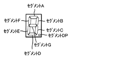
また、ナビ報知を実行する場合には、遊技補助表示器12において数値(図3(b)で
は「8」)を表示するための第1~第7セグメントを正解手順に対応させて点灯制御する
。
Also, when executing the navigation notification, lighting control is performed on the first to seventh segments for displaying a numerical value (“8” in FIG. 3(b)) on the
メイン制御部41は、遊技補助表示器12においてナビ報知を行うためのナビ報知表示
データを設定する。具体的に、図3(a)に示す表示例となるように遊技補助表示器12
の各セグメントを点灯状態とするナビ報知表示データを出力バッファに設定することで、
遊技補助表示器12においてナビ報知を実行するように制御する。一方、ナビ報知を実行
しない場合には、ナビ報知表示データとして出力バッファの初期値を設定、すなわち遊技
補助表示器12の出力バッファを初期化して、遊技補助表示器12のセグメントを全て消
灯状態に設定することで、遊技補助表示器12を非表示に制御する。これにより、遊技補
助表示器12によるナビ報知が実行されない。
The
By setting the navigation notification display data that makes each segment of the lighting state in the output buffer,
The
メイン制御部41は、ゲームが進行して、全てのリール2L,2C,2Rが停止された
ときに、いずれかの役の入賞が発生しているか否かを判定し、払い出しを伴ういずれかの
役(小役)の入賞が発生している場合には、当該入賞の発生により払い出されるメダルの
枚数を払出枚数表示データとして出力バッファに設定して、遊技補助表示器12に払い出
されるメダル枚数を表示させる。
When the game progresses and all the
図3(b)に示すように、払出枚数表示データを出力バッファに設定する際には、メダ
ルの払出枚数を表示させるように遊技補助表示器12の各セグメントを点灯状態とする払
出枚数表示データを出力バッファに設定することで、遊技補助表示器12にメダルの払出
枚数を表示するように制御する。たとえば、8枚のメダルが払い出されるときには、遊技
補助表示器12を構成する左側の表示器と右側の表示器とのうちの右側の表示器の第1~
第7セグメントを点灯させる。これにより、遊技補助表示器12に払い出されるメダルの
枚数を表示させる。
As shown in FIG. 3B, when the payout number display data is set in the output buffer, each segment of the game
Illuminate the seventh segment. As a result, the number of medals to be paid out is displayed on the game
[遊技状態]
図4は、遊技状態の遷移を説明するための図である。図4に示すように、スロットマシ
ン1では、制御可能な遊技状態として、RT0、RT1、RT2、RT3、内部中、およ
びBB(ビッグボーナス)が設けられている。RT0およびRT3は、RT1、RT2、
および内部中よりもリプレイの当選確率が高い遊技状態である。
[Game state]
FIG. 4 is a diagram for explaining the transition of game states. As shown in FIG. 4, in the
And it is a game state in which the winning probability of replay is higher than that in the internal state.
設定変更された後には、まずRT1に制御される。RT1においては、押し順ベルが当
選したときに主役の入賞を取りこぼすと取りこぼし目が導出し、当該取りこぼし目の導出
を条件に、RT0に遊技状態が移行する。RT0においては、転落リプ1が入賞すると、
RT2に遊技状態が移行する。一方、RT0においては、昇格リプが入賞すると、RT3
に遊技状態が移行する。RT2においては、32ゲーム消化すると、RT0に遊技状態が
移行する。RT3においては、押し順ベルが当選したときに主役の入賞を取りこぼすと取
りこぼし目が導出し、当該取りこぼし目の導出を条件に、RT0に遊技状態が移行する。
また、RT3においては、転落リプ2が入賞することによっても、RT0に遊技状態が移
行する。RT0~3のいずれにおいても、BB当選すると、内部中に遊技状態が移行する
。
After the setting is changed, it is first controlled by RT1. In RT1, if the winning prize of the main character is missed when the pushing order bell is won, the missing score is derived, and the game state shifts to RT0 on the condition of deriving the missing score. In RT0, when
The game state shifts to RT2. On the other hand, in RT0, when the promotion reply wins, RT3
The game state shifts to . In RT2, when 32 games are completed, the game state shifts to RT0. In RT3, if the winning prize of the main character is missed when the pushing order bell is won, the missing score is derived, and the game state shifts to RT0 on the condition of deriving the missing score.
In addition, in RT3, the game state shifts to RT0 when the falling
また、RT0およびRT3においては、有利区間G数が1500ゲームに達することで
有利区間が終了すると、有利RTも終了する。ここで、RT1は、設定変更後に移行する
遊技状態であり、かつリプレイの合算確率がRT0やRT3よりも低い遊技状態である。
つまり、RT1は、所謂、遊技状態における初期状態である。有利区間が終了することに
よって、このような初期状態に遊技状態が移行することで、ARTが終了する。
In addition, in RT0 and RT3, when the advantageous interval ends when the number of G in the advantageous interval reaches 1500 games, the advantageous RT also ends. Here, RT1 is a game state to be shifted to after the setting is changed, and is a game state in which the total probability of replay is lower than RT0 and RT3.
That is, RT1 is the initial state in the so-called game state. When the advantageous section ends, the game state shifts to such an initial state, and ART ends.
内部中においては、BB入賞すると、BBに遊技状態が移行する。なお、RT0~3の
いずれかでBB当選したゲームで当該BBに入賞することができれば、内部中を経由する
ことなく、BBに遊技状態が移行する。BBが終了すると、RT1に遊技状態が移行する
。
Inside, when the BB wins, the game state shifts to the BB. Incidentally, if the BB can be won in a game in which the BB is won in any of RT0 to RT3, the game state shifts to the BB without going through the inside. When BB ends, the game state shifts to RT1.
[入賞役]
図5は、特別役および小役を説明するための図である。図5に示すように、入賞役のう
ちの特別役には、BBが含まれる。入賞役のうちの小役には、中段チェリー、右上がりチ
ェリー、下段チェリー、上段スイカ、中段ベル、右下がりベル、上段ベル1~8、および
1枚役1,2が含まれる。上段ベル1~8のそれぞれを構成する中リール2Cの「白BA
R]や「黒BAR」は、中リール2Cにおいて5コマ以内に配置されていない。また、上
段ベル1~8のそれぞれを構成する右リール2Rの「白BAR]や「黒BAR」は、中リ
ール2Cにおいて5コマ以内に配置されていない。このため、内部抽選において上段ベル
1~8に当選していても、中リール2Cや右リール2Rの停止操作を適正なタイミングで
行わなければ、当選している上段ベル1~8を入賞させることができず、上段ベル1~8
の入賞を取りこぼすことになる。このときに導出される出目を取りこぼし目という。各小
役に対応する図柄組合せが導出されると、小役の入賞が発生し、予め決められた枚数分の
メダルが払い出される。
[Winner]
FIG. 5 is a diagram for explaining special wins and minor wins. As shown in FIG. 5, the special combination among the winning combinations includes BB. Small winning combinations include middle cherry, right rising cherry, lower cherry, upper watermelon, middle bell, right falling bell,
R] and "black BAR" are not arranged within 5 frames on the
will miss the prize. The score derived at this time is called a missed score. When the symbol combination corresponding to each minor combination is derived, the minor combination is won, and a predetermined number of medals are paid out.
図6は、再遊技役を説明するための図である。図6に示すように、入賞役のうちの再遊
技役には、通常リプ、制御用リプ1~3、転落リプ1,2、昇格リプ、チェリーリプ、お
よび右下がりスイカリプが含まれる。チェリーリプに対応する図柄組合せのうち、左リー
ル2Lの図柄「チェリー」は、中段チェリーにおける左リール2Lの図柄「チェリー」と
同じである。一方、チェリーリプに対応する図柄組合せのうち、中リール2Cおよび右リ
ール2Rの図柄は、中段チェリーにおける中リール2Cおよび右リール2Rの図柄と異な
る。
FIG. 6 is a diagram for explaining a replay combination. As shown in FIG. 6, the replaying hands among the winning hands include normal lips,
[抽選対象役]
図7は、抽選対象役を説明するための図である。抽選対象役は、スロットマシン1が実
行する内部抽選の対象となる役である。内部抽選は、メイン制御部41によって実行され
、導出を許容する図柄組合せを決定する処理である。なお、内部抽選によって図柄組合せ
の導出が許容されると、当該図柄組合せに対応する役に当選したことになる。
[Lottery target role]
FIG. 7 is a diagram for explaining the lottery target combination. The lottery target combination is a combination that is the target of an internal lottery executed by the
図7に示すように、役番号欄には抽選対象役ごとに割り当てられた役番号1~48が示
され、抽選対象役欄には抽選対象役の名称が示され、遊技状態欄にはRTの種類ごとに丸
印で抽選対象となる抽選対象役が示され、設定差欄には丸印で設定差の有無が示され、有
利区間移行欄には丸印で有利区間当選の有無が示され、メイン報知タイミング欄には丸印
で先報知および後報知のいずれであるかが示されている。
As shown in FIG. 7, the win number column shows
図7に示す抽選テーブルでは、割り当てられた役番号の大きい抽選対象役から順に上か
ら並べられている。メイン制御部41は、賭数設定後、スタートスイッチ7が操作された
ときに、内部抽選を行う。メイン制御部41は、内部抽選処理において、役番号の大きい
抽選対象役から順に当選したか否かを判定する。たとえば、内部抽選処理において、メイ
ン制御部41は、所定範囲内(0~65535)の整数から乱数を取得する。各抽選対象
役には所定範囲内(0~65535)の整数のうちから予めRT状態に応じた判定値数が
割り当てられている。たとえば、中段チェリー1はいずれのRT状態においても6543
2~65535の4個の判定値数が割り当てられている。メイン制御部41は、取得した
乱数に対して、役番号の大きい抽選対象役から順に判定値数を加算していき、加算結果が
オーバーフローした(65535を超えた)ときに、その時点で加算対象となっていた抽
選対象役を当選役に決定する。このように、メイン制御部41は、予め割り当てられた役
番号の大きい順に各抽選対象役に対して内部抽選を行う。
In the lottery table shown in FIG. 7, the lottery target combinations are arranged in descending order of assigned combination number. The
Four decision value numbers from 2 to 65535 are assigned. The
各抽選対象役は、カテゴリごとに区分されて役番号が割り当てられている。本実施の形
態におけるカテゴリとは、抽選対象役の性質や役割、あるいは機能などによって区分され
るグループを意味する。たとえば、本実施の形態におけるカテゴリには、有利区間当選す
るカテゴリ、有利区間当選しないカテゴリ、設定差ありのカテゴリ、設定差なしのカテゴ
リ、メイン報知のタイミングが先報知になるカテゴリ、メイン報知のタイミングが後報知
になり得るカテゴリ、RT状態に応じて当選確率(判定値数)が変化しないカテゴリ、R
T状態に応じて当選確率(判定値数)が変化するカテゴリ、特別役のカテゴリ、小役のカ
テゴリ、再遊技役のカテゴリ、および押し順役のカテゴリが含まれる。有利区間当選する
カテゴリの役は、有利区間当選しないカテゴリの役よりも、数字の大きい役番号が割り当
てられている。具体的には、移行対象役には役番号35~48が割り当てられ、移行対象
役でない役には役番号1~34が割り当てられている。これにより、移行対象役は、移行
対象役でない役よりも優先的に内部抽選が行われる。
Each lottery target combination is classified by category and assigned a combination number. A category in the present embodiment means a group classified according to the nature, role, function, or the like of the lottery target combination. For example, the categories in the present embodiment include a category in which an advantageous section is won, a category in which an advantageous section is not won, a category with a setting difference, a category without a setting difference, a category in which the timing of the main notification is the first notification, and the timing of the main notification. is a category that can be notified later, a category in which the winning probability (number of judgment values) does not change according to the RT state, R
It includes a category in which the probability of winning (the number of judgment values) changes according to the T state, a special combination category, a small combination category, a replay combination category, and a winning combination combination category. Winning category wins in an advantageous interval are assigned larger win numbers than categories winning in an advantageous interval. Specifically, the combination numbers 35 to 48 are assigned to the roles to be transferred, and the
メイン制御部41は、内部抽選で当選した役番号が、移行対象役に割り当てられている
35以上の数であれば、特定の抽選種別1のビットを立てる。このようにして、メイン制
御部41は、移行対象役の当選情報のみを抽選種別1に格納する。そして、メイン制御部
41は、有利区間移行の有無を決定する処理において、抽選種別1に含まれるデータにお
いてビットが立てられているか否かを判定し、ビットが立てられていれば、有利区間への
移行を決定する。抽選種別1においてビットが立てられる契機となる役は、移行対象役に
限られているため、メイン制御部41は、抽選種別1に含まれるデータを参照するだけで
有利区間に移行するか否かを決定することができる。これにより、有利区間に移行するか
否かを決定する際に用いるデータ領域を一元管理することができる。
The
役番号35~48が割り当てられた移行対象役のうち、メイン報知のタイミングが先報
知になるカテゴリの役は、メイン報知のタイミングが後報知になり得るカテゴリの役より
も、数字の大きい役番号が割り当てられている。具体的には、メイン報知のタイミングが
先報知になるカテゴリの役には役番号38~48が割り当てられ、メイン報知のタイミン
グが後報知になり得るカテゴリの役には役番号35~37が割り当てられている。
Of the wins to be transitioned to which win
役番号1~34が割り当てられた移行対象役でない役のうち、遊技状態に応じて当選確
率(判定値数)が変化しないカテゴリの役は、遊技状態に応じて当選確率(判定値数)が
変化するカテゴリの役よりも、数字の大きい役番号が割り当てられている。具体的には、
遊技状態に応じて当選確率(判定値数)が変化しないカテゴリの役には役番号13~31
が割り当てられ、遊技状態に応じて当選確率(判定値数)が変化するカテゴリの役には役
番号1~12が割り当てられている。
Of the non-transferable hands to which the
Winning probability (number of judgment values) does not change according to the game state.
are assigned, and
さらに、上述した役番号の割り当て規則を前提とした上で、特別役のカテゴリ、小役の
カテゴリ、再遊技役のカテゴリの順に、数字の大きい役番号が割り当てられている。なお
、同じ種類の役(たとえば、チェリー、スイカ、押し順ベル、昇転リプ、維持転リプなど
)は、役番号の数字が連続するようにまとめられている。
Furthermore, on the premise of the above-described combination number assignment rule, the combination numbers with the larger numbers are assigned in the order of the special combination category, the small combination category, and the replay combination category. Note that the same type of hands (for example, cherry, watermelon, pushing order bell, ascending roll, sustaining roll, etc.) are grouped so that the numbers of the combination numbers are consecutive.
図7に示すように、設定差なしのカテゴリの役は移行対象役になり得るが、設定差あり
のカテゴリの役は移行対象役にならない。たとえば、役番号46の強チェリー1、および
役番号35のBB+強チェリー1は、設定差なしのカテゴリの役であり、移行対象役に定
められている。一方、役番号33のBB+強チェリー2は、設定差ありのカテゴリの役で
あり、移行対象役に定められていない。その他の設定差のある役についても同様に、移行
対象役に定められていない。なお、設定差なしのカテゴリの役であっても、移行対象役に
定められていない場合もある。たとえば、役番号32のBB+強チェリー3は、設定差な
しのカテゴリの役であるが、移行対象役に定められていない。
As shown in FIG. 7, the wins in the category without setting difference can be transitioned, but the wins in the category with setting difference cannot be transitioned. For example, the
強チェリー1、強チェリー2、および強チェリー3は、いずれも右上がりチェリーの図
柄組合せを導出可能な役であるが、役番号に応じて、BB当選の有無、設定差の有無、お
よび有利区間当選の有無が異なる。たとえば、役番号46の強チェリー1は、BB当選な
し、設定差なし、有利区間当選ありの役である。役番号35のBB+強チェリー1は、B
B当選あり、設定差なし、有利区間当選ありの役である。役番号33のBB+強チェリー
2は、BB当選あり、設定差あり、有利区間当選なしの役である。役番号32のBB+強
チェリー3は、BB当選あり、設定差なし、有利区間当選なしの役である。このように、
右上がりチェリーの図柄組合せを導出可能な強チェリー役は、BB当選および有利区間当
選のいずれかが決定される役である。
It is a combination with B winning, no setting difference, and winning in an advantageous section. The
A strong cherry combination from which a symbol combination of rising cherry can be derived is a combination in which either BB winning or advantageous section winning is determined.
[判定値数のデータ構造]
図8は、判定値数のデータ構造を説明するための図である。図8に示すデータ構造は、
たとえば、RAM41cに格納された遊技進行用のプログラムに含まれるデータ構造であ
る。このデータ構造では、基本的には役番号の数字が大きい順に各抽選対象役に定められ
た判定値のデータが格納されているが、以下で説明するように配置されている。
[Data structure of number of judgment values]
FIG. 8 is a diagram for explaining the data structure of the number of judgment values. The data structure shown in FIG.
For example, it is a data structure included in a game progress program stored in the
具体的には、図8に示すデータ構造では、設定差なしのカテゴリの役に定められた判定
値のデータと、設定差ありのカテゴリの役に定められた判定値のデータとが区分されてい
る。たとえば、設定差ありの役番号14,27,28,30,33,34の抽選対象役の
判定値のデータは、その他の設定差なしの役の判定値のデータと区分されている。このよ
うに、設定差の有無に応じて判定値のデータの配置箇所が分かれている。
Specifically, in the data structure shown in FIG. 8, the data of the judgment value determined for the category with no setting difference and the data of the determination value determined for the category with the setting difference are separated. there is For example, the determination value data for the lottery target combinations with set differences of
設定差なしのカテゴリの役に定められた判定値のデータのうち、1バイトデータに収ま
る判定値のデータ(設定差なし1バイトデータ)と、1バイトデータに収まらないが2バ
イトデータに収まる判定値のデータ(設定差なし2バイトデータ)とで区分されている。
なお、1バイトデータに対応する判定値数は256である。このため、256を超える判
定値数が定められた抽選対象役は、2バイトデータ内に配置される。たとえば、1バイト
データに収まる判定値数「4」の中段チェリー1は、1バイトデータ内に配置されている
。一方、1バイトデータに収まらないが2バイトデータに収まる判定値数「1149」の
左ベル1は、2バイトデータ内に配置されている。このように、設定差の有無およびバイ
トデータの容量に応じて判定値のデータの配置箇所が分かれている。
Of the judgment value data defined for the role of the no set difference category, judgment value data that fits in 1 byte data (1 byte data without set difference) and judgment that does not fit in 1 byte data but fits in 2 byte data It is separated from the value data (2-byte data without setting difference).
Note that the number of determination values corresponding to 1-byte data is 256. Therefore, the lottery winning combination for which the number of judgment values exceeding 256 is determined is arranged in the 2-byte data. For example, the
さらに、設定差なし1バイトデータにおいては、互いに同じ判定値数が定められた抽選
対象役は、判定値のデータがまとめられている。たとえば、互いに同じ判定値数「4」が
定められた中段チェリー1,2は、判定値のデータがまとめられている。さらに、設定差
なし1バイトデータにおいては、役番号の数字が大きい順に各抽選対象役に定められた判
定値のデータが格納されている。たとえば、設定差なし1バイトデータにおいては、役番
号48の中段チェリー1、役番号47の中段チェリー2の順に判定値のデータが配置され
ている。また、設定差なし2バイトデータにおいては、互いに同じ判定値数が定められた
抽選対象役は、判定値のデータがまとめられている。たとえば、互いに同じ判定値数「1
149」が定められた左ベル1~4、中ベル1~4、右ベル1~4は、判定値のデータが
まとめられている。このように、設定差なしの抽選対象役のうち、判定値数が同じ抽選対
象役同士はまとめられている。さらに、設定差なし2バイトデータにおいては、役番号の
数字が大きい順に各抽選対象役に定められた判定値のデータが格納されている。たとえば
、設定差なし2バイトデータにおいては、役番号26の左ベル1、役番号25の左ベル2
の順に判定値のデータが配置されている。
Further, in the 1-byte data with no setting difference, the determination value data is collected for the lottery target combination for which the same number of determination values is determined. For example, the data of the judgment values are grouped together for the
149” are defined, the data of the judgment values are summarized for the
Judgment value data is arranged in the order of .
設定差ありの抽選対象役に定められた判定値のデータのうち、1バイトデータに収まる
判定値のデータ(設定差あり1バイトデータ)と、1バイトデータに収まらないが2バイ
トデータに収まる判定値のデータ(設定差あり2バイトデータ)とが区分されている。た
とえば、1バイトデータに収まる各設定値に対応する判定値数「22」~「69」のBB
は、1バイトデータ内に配置されている。さらに、設定差あり1バイトデータにおいては
、役番号の数字が大きい順に各抽選対象役に定められた判定値のデータが格納されている
。たとえば、設定差あり1バイトデータにおいては、役番号34のBB、役番号33のB
B+強チェリー2の順に判定値のデータが配置されている。また、1バイトデータに収ま
らないが2バイトデータに収まる各設定値に対応する判定値数「3074」~「4254
」のベルは、2バイトデータ内に配置されている。さらに、設定差あり2バイトデータに
おいては、役番号の数字が大きい順に各抽選対象役に定められた判定値のデータが格納さ
れている。たとえば、設定差あり2バイトデータにおいては、役番号27のベル、役番号
14の1枚役の順に判定値のデータが配置されている。このように、設定差ありの抽選対
象役のうち、判定値数が同じ抽選対象役同士はまとめられ、さらに役番号の数字が大きい
順に各抽選対象役に定められ判定値のデータが格納されている。
Among the judgment value data determined for the lottery target role with set difference, the judgment value data that fits in 1 byte data (1 byte data with set difference), and the judgment value that does not fit in 1 byte data but fits in 2 byte data It is separated from value data (2-byte data with setting difference). For example, BB with the number of judgment values "22" to "69" corresponding to each setting value that fits in 1 byte data
is placed within 1-byte data. Further, in the 1-byte data with setting difference, the data of the judgment value determined for each lottery target combination is stored in descending order of the combination number. For example, in the 1-byte data with setting difference, BB of winning
Judgment value data is arranged in the order of B+
” is located within the 2-byte data. Further, in the 2-byte data with setting difference, the data of the determination values determined for each lottery target combination are stored in descending order of the combination numbers. For example, in the 2-byte data with setting difference, the judgment value data are arranged in the order of the bell of the
[抽選対象役により入賞が許容される役の組合せ]
図9は、抽選対象役により入賞が許容される役の組合せについて説明するための図であ
る。図9に示すように、各抽選対象役は、単数あるいは複数の役が組み合わされて抽選対
象となる。
[Combinations of roles for which prizes are allowed depending on the lottery target role]
FIG. 9 is a diagram for explaining a combination of winnings that are permitted according to the lottery target winnings. As shown in FIG. 9, each lottery target combination is a lottery target with a single combination or a combination of a plurality of combinations.
たとえば、中段チェリー1,2のいずれにおいても、中段チェリーが含まれる。このた
め、中段チェリー1,2のいずれに当選したときでも、ストップスイッチ8Lの操作タイ
ミングに応じて左リール2Lの中段にチェリー図柄が停止する。また、チェリーリプ1,
2のいずれにおいても、チェリーリプが含まれる。このため、チェリーリプ1,2のいず
れに当選したときでも、ストップスイッチ8Lの操作タイミングに応じて左リール2Lの
中段にチェリー図柄が停止する。
For example, both
2 includes cherry lips. Therefore, regardless of whether
[押し順役当選時のリール制御]
図10は、押し順ベル当選時のリール制御を説明するための図である。図10に示すよ
うに、押し順ベルは、その種類に応じて正解手順が定められている。たとえば、左ベル1
~4には正解手順として左第1停止が定められ、中ベル1~4には正解手順として中第1
停止が定められ、右ベル1~4には正解手順として右第1停止が定められている。いずれ
かの押し順ベルに当選したときに正解手順でストップスイッチが操作されると、主役であ
る右下がりベルや中段ベルが入賞し、不正解手順でストップスイッチが操作されると、副
役であるいずれかの上段ベルが入賞するか、あるいは入賞を取りこぼして取りこぼし目が
導出される。なお、有利区間中においては、押し順ベル当選時に正解手順がナビ報知によ
って報知され得る。
[Reel control when winning a push order]
FIG. 10 is a diagram for explaining the reel control when the bell is won in the pressing order. As shown in FIG. 10, the correct procedure is determined according to the type of the push order bell. For example,
The correct procedure for 1 to 4 is the left first stop, and the correct procedure for
Stops are defined, and the right first stop is defined as the correct procedure for the right bells 1-4. If the stop switch is operated in the correct order when one of the push order bells is won, the leading bell or middle bell will win a prize, and if the stop switch is operated in the incorrect order, it will be a secondary role. Either one of the upper bells wins, or the winnings are dropped to derive the missing numbers. It should be noted that, during the advantageous section, the correct procedure can be announced by the navigation announcement when the winning order of the bell is won.
図11は、押し順リプ当選時のリール制御を説明するための図である。図11に示すよ
うに、押し順リプは、その種類に応じて正解手順が定められている。たとえば、昇転リプ
1には正解手順として順押し(左、中、右の停止操作順)が定められ、昇転リプ2には正
解手順として挟み押し(左、右、中の停止操作順)が定められ、昇転リプ3には正解手順
として中左押し(中、左、右の停止操作順)が定められている。昇転リプ1~6のいずれ
かに当選したときに正解手順でストップスイッチが操作されると、昇格リプが入賞し、不
正解手順でストップスイッチが操作されると、転落リプ1が入賞する。このように、押し
順リプ当選時においては、遊技者が正解手順を選択したか否かに応じて入賞の発生を異な
らせることができる。なお、有利区間中においては、押し順リプ当選時に正解手順がナビ
報知によって報知され得る。
FIG. 11 is a diagram for explaining the reel control at the time of winning the push order reply. As shown in FIG. 11, the correct procedure is determined according to the type of the push order slip. For example, the correct procedure for ascending
[BB示唆演出]
中段チェリー1,2、および強チェリー1は、単独当選することもあるし、BBと同時
当選することもある。このようなBBと同時当選可能な抽選対象役が当選したときには、
当該抽選対象役が当選したゲーム以降のゲームにおいて、BB当選しているか否かを示唆
するBB示唆演出が実行され得る。
[BB suggestion production]
In the game after the game in which the lottery target role is won, a BB suggesting effect to suggest whether or not the BB is won can be executed.
たとえば、強チェリー1に当選したときには、ストップスイッチの操作タイミングに応
じて右上がりにチェリー図柄が揃う。このとき、遊技者は、強チェリー1に当選したこと
を認識でき、さらにBBにも当選していることを期待する。そこで、強チェリー1に当選
したゲーム以降でBB示唆演出が実行される。
For example, when the
たとえば、BB示唆演出では、キャラクタによるバトル演出が行われ、当該バトル演出
の結果として味方キャラクタが敵キャラクタに勝利すればBB当選確定となる。BB当選
の確定報知では、たとえば、「WIN」の文字画像が液晶表示器51に表示される。そし
て、BB当選が確定すれば、当選を持ち越しているBBを入賞させることができるゲーム
(たとえば、内部抽選でハズレになったゲーム)において、7図柄揃いを促す「7を狙え
」の文字画像が液晶表示器51に表示される。一方、バトル演出の結果として味方キャラ
クタが敵キャラクタに敗北すればBB当選がなかったことになる。なお、BB示唆演出は
、1ゲーム内で完結するものであってもよいし、複数ゲームに亘る連続演出であってもよ
い。
For example, in the BB suggestion effect, a battle effect is performed by the characters, and if the ally character wins the enemy character as a result of the battle effect, the BB win is confirmed. For example, a character image of "WIN" is displayed on the
このように、BBと同時当選可能な抽選対象役が当選した以降のゲームでBB示唆演出
が実行されることにより、BB当選していることに対して遊技者に期待させることができ
、遊技の興趣を向上させることができる。
In this way, by executing the BB suggesting effect in the game after the lottery target combination that can be won simultaneously with the BB is won, the player can be made to expect that the BB is won, and the game progresses. Interest can be improved.
[メイン報知のタイミング]
図12は、メイン報知のタイミングを説明するための図である。図12に示すように、
役番号35~48の各移行対象役には、役の種類ごとにメイン報知のタイミングが定めら
れている。
[Timing of main notification]
FIG. 12 is a diagram for explaining the timing of main notification. As shown in FIG.
The timing of the main notification is determined for each type of combination for each of the combination numbers 35 to 48 to be transferred.
具体的には、BB当選しない移行対象役に当選した場合、先報知が行われる。この場合
の先報知タイミングとしては、スタートスイッチ7によるスタート操作時、ストップスイ
ッチによる第1停止操作時、ストップスイッチによる第2停止操作時、ストップスイッチ
による第3停止操作時、第3停止操作が離されて表示結果が導出されたとき、払出終了時
、およびリプレイ入賞による自動賭数設定の完了時(たとえば、3BET目が完了したと
き)といった各タイミングが設けられている。たとえば、役番号48の中段チェリー1に
当選した場合、第3停止操作が離されて表示結果が導出されたときに、有利区間ランプ1
9の点灯によってメイン報知が行われる。
Specifically, when a win is won for a combination to be transferred that does not win a BB win, advance notification is made. In this case, the timing of prior notification is when the start operation is performed by the
The main notification is performed by the lighting of 9.
BB当選する移行対象役に当選した場合、先報知および後報知のいずれかが行われる。
この場合の先報知タイミングとしては、第3停止操作が離されて表示結果が導出されたタ
イミングが設けられている。後報知タイミングとしては、BBの図柄組合せが導出されて
BB入賞したゲーム内のタイミングが設けられている。メイン制御部41は、BB当選す
る移行対象役に当選したときに、抽選によって先報知および後報知のいずれかに決定する
(本実施の形態においては、先報知50%、後報知50%で、それぞれ決定される)。
When the BB winning transition target combination is won, either the pre-notification or the post-notification is performed.
As the preceding notification timing in this case, the timing at which the third stop operation is released and the display result is derived is provided. As the post notification timing, the timing in the game when the BB symbol combination is derived and the BB is won is provided. The
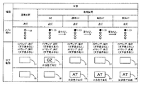
[メイン報知およびサブ報知の点灯態様]
図13を参照しながら、メイン制御部41による有利区間ランプ19の点灯制御によっ
て行われるメイン報知と、サブ制御部91によるCZランプ57およびATランプ58の
点灯制御によって行われるサブ報知とについて説明する。図13は、メイン報知およびサ
ブ報知の態様を説明するための図である。
[Lighting mode of main notification and sub-notification]
13, the main notification performed by controlling the lighting of the
先ず、通常区間におけるメイン報知について説明する。通常区間においては、メイン報
知は行われない。具体的には、図13に示すように、通常区間においては、有利区間ラン
プ19は、消灯したままである。
First, the main notification in the normal section will be described. Main notification is not performed in the normal section. Specifically, as shown in FIG. 13, the
次に、通常区間におけるサブ報知について説明する。通常区間においては、サブ報知は
行われない。具体的には、通常区間においては、CZランプ57およびATランプ58は
、いずれも消灯しており、CZやATの文字が表示されない。
Next, the sub-notification in the normal section will be described. Sub-notification is not performed in the normal section. Specifically, in the normal section, both the
次に、有利区間におけるメイン報知について説明する。有利区間においては、メイン報
知が行われる。しかし、メイン報知は、有利区間の種類に応じてその態様を変化させない
。具体的には、有利区間では、CZ,通常AT、有利AT、特別ATの順に遊技区間が昇
格し得る。先ず、通常区間からCZに移行すると、有利区間ランプ19が白色に点灯する
。その後、CZから通常AT、有利AT、特別ATの順に遊技区間が昇格しても、有利区
間ランプ19は白色に点灯したままである。
Next, the main notification in the advantageous section will be described. The main notification is performed in the advantageous section. However, the main notification does not change its form according to the type of advantageous section. Specifically, in the advantageous section, the game section can be promoted in the order of CZ, normal AT, advantageous AT, and special AT. First, when the normal section shifts to CZ, the
このように、メイン報知では、有利区間の種類に関わらず一定の態様で有利区間の制御
中である旨が示唆される。
In this way, the main notification indicates that the advantageous section is being controlled in a fixed manner regardless of the type of the advantageous section.
なお、メイン報知における有利区間ランプ19の点灯色は、図13に示す例(白色)に
限らず、青色や黄色など他の色であってもよい。また、メイン報知における有利区間ラン
プ19の点灯態様は、図13に示す例(点灯)に限らず、点滅など他の態様であってもよ
い。ただし、いずれの態様を採用したとしても、メイン報知では、有利区間の種類に関わ
らず一定の態様で有利区間の制御中である旨が示唆される。
The lighting color of the
次に、有利区間におけるサブ報知について説明する。有利区間においては、サブ報知が
行われる。さらに、サブ報知は、有利区間の種類に応じてその態様を変化させる。具体的
には、通常区間からCZに移行すると、CZランプ57が白色で点灯する。CZランプ5
7が点灯することで、CZランプ57において「CZ」の文字が表示される。その後、C
Zから通常ATに移行すると、CZランプ57が消灯し、代わりにATランプ58が白色
で点灯する。CZランプ57が消灯することで、CZランプ57において「CZ」の文字
が消えるが、ATランプ58が点灯することで、ATランプ58において「AT」の文字
が表示される。
Next, the sub-notification in the advantageous section will be described. Sub-notification is performed in the advantageous section. Furthermore, the sub-notification changes its aspect according to the type of the advantageous section. Specifically, when the normal section shifts to CZ, the
7 is turned on, the characters “CZ” are displayed on the
When shifting from Z to normal AT, the
その後、通常ATから有利ATに移行すると、ATランプ58が赤色で点灯する。この
ように、通常ATから有利ATに移行すると、ATランプ58の点灯色が変化する。その
後、有利ATから特別ATに移行すると、ATランプ58が点灯から点滅に変わる。この
ように、有利ATから特別ATに移行すると、ATランプ58の点灯態様が変化する。
After that, when the normal AT shifts to the advantageous AT, the
このように、サブ報知では、有利区間の種類に応じた態様で有利区間の制御中である旨
が示唆される。
In this way, the sub-notification indicates that the advantageous section is being controlled in a mode corresponding to the type of the advantageous section.
なお、サブ報知におけるCZランプ57の点灯色は、図13に示す例(白色)に限らず
、青色や黄色など他の色であってもよい。また、サブ報知におけるCZランプ57の点灯
態様は、図13に示す例(点灯)に限らず、点滅など他の態様であってもよい。同様に、
サブ報知におけるATランプ58の点灯色は、図13に示す例(通常ATが白色、有利A
Tおよび特別ATが赤色)に限らない。たとえば、通常AT、有利AT、および特別AT
のそれぞれが異なる点灯色で点灯してもよい。また、サブ報知におけるATランプ58の
点灯態様は、図13に示す例(通常ATおよび有利ATが点灯、特別ATが点滅)に限ら
ない。たとえば、通常AT、有利AT、および特別ATのそれぞれが異なる点灯態様で点
灯してもよい。具体的には、通常ATが点灯、有利ATが遅い点滅、特別ATが早い点滅
であってもよい。
The lighting color of the
The lighting color of the
T and special AT are red). For example, normal AT, favorable AT, and special AT
may be illuminated in different lighting colors. Further, the lighting mode of the
以上、図13に示すように、メイン制御部41による有利区間ランプ19の点灯制御に
よって行われるメイン報知では、有利区間の種類に関わらず一定の態様で有利区間の制御
中である旨が示唆される。一方、サブ制御部91によるCZランプ57およびATランプ
58の点灯制御によって行われるサブ報知では、有利区間の種類に応じた態様で有利区間
の制御中である旨が示唆される。
As described above, as shown in FIG. 13, the main notification performed by controlling the lighting of the
メイン制御部41が備えるRAM41cは、サブ制御部91が備えるRAM91cより
も記憶容量が小さい。このため、メイン報知の態様を、有利区間の種類に関わらず一定に
することで、記憶容量の増大を極力抑えることができる。また、メイン制御部41による
有利区間の制御中である旨の示唆に係る処理負担の増大を極力抑えることもできる。一方
、サブ制御部91が備えるRAM91cでは、サブ報知に必要なデータをある程度記憶さ
せておくことができる。このため、サブ報知の態様を、有利区間の種類に応じて変化させ
ることで、メイン報知による有利区間の制御中である旨の示唆の簡素化を補うことができ
る。
The
具体的には、メイン報知は、通常区間であるか、あるいは有利区間であるかのみを遊技
者に示唆するものであり、有利区間の種類までは示唆することができない。しかし、サブ
報知によって有利区間の種類までは示唆することで、遊技の興趣を向上させることができ
る。
Specifically, the main notification only suggests to the player whether it is a normal section or an advantageous section, and cannot suggest the type of advantageous section. However, by suggesting even the kind of advantageous section by the sub-notification, it is possible to improve the interest of the game.
[メイン報知のタイミングおよびBB示唆演出の有無の一例]
図14~図17は、メイン報知のタイミングおよびBB示唆演出の有無の一例を説明す
るための図である。
[Example of timing of main notification and presence/absence of BB suggestion effect]
14 to 17 are diagrams for explaining an example of the timing of the main notification and the presence/absence of the BB suggestive effect.
図14(a)は、移行対象役がBBと同時当選し、かつ有利区間当選によって先報知が
行われる場合の一例を示す。
FIG. 14(a) shows an example of a case where the transition target combination is won simultaneously with the BB, and advance notification is made by winning an advantageous section.
図14(a)に示すように、タイミングt1で移行対象役がBBと同時当選しかつ有利
区間当選した場合、当該移行対象役が当選したゲーム内のタイミングt2で先報知が行わ
れる。その後、タイミングt3で有利区間に制御される。また、このとき、BB示唆演出
の実行が開始する。
As shown in FIG. 14(a), when the transition target combination wins simultaneously with the BB at timing t1 and wins the advantageous section, advance notification is made at timing t2 in the game when the transition target combination wins. After that, at timing t3, it is controlled to the advantageous section. Also, at this time, the execution of the BB suggestion effect is started.
複数ゲームに亘ってBB示唆演出が実行された後、内部抽選でハズレになったタイミン
グt4でBB当選の確定報知が行われる。たとえば、内部抽選でハズレになったゲームの
スタート操作時に「WIN」の文字画像が液晶表示器51に表示され、その後、7図柄揃
いを促す「7を狙え」の文字画像が液晶表示器51に表示される。タイミングt5におい
てBBが入賞すると、次のゲームのタイミングt6からBBに制御される。それ以降は、
BB中における有利区間となる。
After the BB suggestive effect is executed over a plurality of games, the BB winning confirmation notification is performed at the timing t4 when the internal lottery is lost. For example, a character image of "WIN" is displayed on the
It becomes an advantageous section in BB.
図14(b)は、移行対象役がBBと同時当選し、かつ有利区間当選しなかった場合の
一例を示す。図14(b)に示す例では、図14(a)に示す例と異なり、メイン報知が
行われず有利区間にも制御されない。それ以外の制御については、図14(a)に示す例
と同じである。
FIG. 14(b) shows an example of a case where the transition target combination is won at the same time as the BB and the advantageous zone is not won. In the example shown in FIG. 14(b), unlike the example shown in FIG. 14(a), the main notification is not performed and the advantageous section is not controlled. Other controls are the same as the example shown in FIG.
図15(c)は、移行対象役がBBと同時当選せず、かつ有利区間当選によって先報知
が行われる場合の一例を示す。さらに、図15(c)は、BB示唆演出が実行される場合
の一例である。なお、BB当選していないため、このBB示唆演出は所謂ガセ演出になる
。
FIG. 15(c) shows an example of a case where the transition target combination is not won at the same time as the BB, and advance notification is made by winning an advantageous section. Furthermore, FIG. 15(c) is an example of the case where the BB suggestion effect is executed. In addition, since the BB has not been won, this BB suggestion effect is a so-called fake effect.
図15(c)に示すように、タイミングt1で移行対象役が単独当選しかつ有利区間当
選した場合、当該移行対象役が当選したゲーム内でBBに制御されるか否かを示唆する発
展演出が実行される。そして、当該ゲーム内のタイミングt2で先報知が行われる。その
後、タイミングt3で有利区間に制御される。また、このとき、BB示唆演出の実行が開
始する。
As shown in FIG. 15(c), when a single winning combination for transition is won at timing t1 and an advantageous section is won, a developmental effect indicating whether or not the BB will be controlled in the game in which the winning combination for transition is won. is executed. Then, advance notification is performed at timing t2 in the game. After that, at timing t3, it is controlled to the advantageous section. Also, at this time, the execution of the BB suggestion effect is started.
複数ゲームに亘ってBB示唆演出が実行されている期間では、前兆状態に制御され、B
B示唆演出が実行された後のタイミングt4でBB当選のハズレ報知(たとえば、「LO
SE」の文字画像が液晶表示器51に表示)が行われると、それ以降、BBへは制御され
ないが、CZに制御される。このように、先報知が行われないときに発展演出が実行され
た後にBB示唆演出が実行されると、BBへの制御に対して遊技者に期待させることがで
きる。また、BB当選のハズレ報知が行われてBBに制御されなくとも、それ以降はCZ
に制御されるため、遊技の興趣を向上させることができる。
During the period in which the BB suggestive effect is being executed over a plurality of games, the premonitory state is controlled, and the B
At timing t4 after the B suggestion effect is executed, the BB winning loss notification (for example, "LO
When the character image "SE" is displayed on the liquid crystal display 51), control is not performed to BB, but is controlled to CZ. In this way, if the BB suggesting effect is executed after the development effect is executed when the advance notification is not performed, the player can be expected to control the BB. Also, even if the BB election loss notification is performed and it is not controlled by the BB, after that, the CZ
is controlled, it is possible to improve the amusement of the game.
図15(d)は、移行対象役がBBと同時当選せず、かつ有利区間当選によって先報知
が行われる場合の一例を示す。図15(d)に示す例では、図15(c)に示す例と異な
り、BB示唆演出が実行されない。たとえば、タイミングt1で移行対象役が単独当選し
かつ有利区間当選した場合、当該移行対象役が当選したゲーム内でCZ演出が実行される
。これにより、遊技者に対してCZへの制御を確定報知することができる。その後、先報
知が行われた以降、前兆状態を経由することなくCZに制御される。
FIG. 15(d) shows an example of a case where the transition target combination is not won at the same time as the BB, and advance notification is made by winning an advantageous section. In the example shown in FIG. 15(d), unlike the example shown in FIG. 15(c), the BB suggestion effect is not executed. For example, when a single winning combination for transition is won at timing t1 and an advantage section is won, the CZ effect is executed in the game in which the combination for transition is won. As a result, it is possible to notify the player of the control to the CZ. After that, after the advance notification is performed, the control is performed to CZ without going through the precursor state.
図16(e)は、移行対象役がBBと同時当選せず、かつ有利区間当選しなかった場合
の一例を示す。さらに、図16(e)は、BB示唆演出が実行される場合の一例である。
なお、BB当選していないため、このBB示唆演出は所謂ガセ演出になる。
FIG. 16(e) shows an example of a case where the transition target combination is not won simultaneously with the BB and the advantage section is not won. Furthermore, FIG. 16(e) is an example of the case where the BB suggestion effect is executed.
In addition, since the BB has not been won, this BB suggestion effect is a so-called fake effect.
図16(e)に示すように、タイミングt1で移行対象役が単独当選しかつ有利区間当
選しなかった場合、メイン報知が行われない。次のゲームのタイミングt2でBB示唆演
出の実行が開始する。
As shown in FIG. 16(e), when the transition target combination is single-won at timing t1 and the advantage section is not won, the main notification is not performed. At timing t2 of the next game, the execution of the BB suggestion effect is started.
複数ゲームに亘ってBB示唆演出が実行された後、タイミングt3でBB当選のハズレ
報知が行われる。たとえば、「LOSE」の文字画像が液晶表示器51に表示される。
After the BB suggestive effect is executed over a plurality of games, the BB winning loss notification is performed at timing t3. For example, a character image of “LOSE” is displayed on the
図16(f)は、移行対象役がBBと同時当選せず、かつ有利区間当選しなかった場合
の一例を示す。図16(f)に示す例では、図16(e)に示す例と異なり、BB示唆演
出が実行されない。それ以外の制御については、図16(e)に示す例と同じである。
FIG. 16(f) shows an example of a case where the transition target combination is not won simultaneously with the BB and the advantageous zone is not won. In the example shown in FIG. 16(f), unlike the example shown in FIG. 16(e), the BB suggestion effect is not executed. Other controls are the same as the example shown in FIG.
図17(g)は、移行対象役がBBと同時当選し、かつ有利区間当選によって後報知が
行われる場合の一例を示す。
FIG. 17(g) shows an example of a case where the transition target combination is won at the same time as the BB, and the post-notification is performed by winning the advantageous section.
図17(g)に示すように、タイミングt1で移行対象役がBBと同時当選しかつ有利
区間当選しているが、この例では先報知が行われない。このため、移行対象役に当選した
ゲームの次のゲームのタイミングt2で待機区間に制御される。また、このとき、BB示
唆演出の実行が開始する。
As shown in FIG. 17(g), at timing t1, the transition target combination is won at the same time as BB, and the advantageous section is won, but in this example, advance notification is not performed. Therefore, the game is controlled to the waiting section at the timing t2 of the game following the game in which the transition target role is won. Also, at this time, the execution of the BB suggestion effect is started.
複数ゲームに亘ってBB示唆演出が実行された後、内部抽選でハズレになったタイミン
グt3でBB当選の確定報知が行われる。タイミングt4においてBBが入賞するときに
は、後報知が行われる。その後、次のゲームの賭数設定が可能となったタイミングt5か
らBBに制御されるとともに、有利区間に制御される。それ以降は、BB中における有利
区間となる。
After the BB suggestive effect is executed over a plurality of games, BB winning confirmation notification is performed at timing t3 when the internal lottery is lost. When BB wins at timing t4, post-notification is performed. After that, from the timing t5 when the number of bets for the next game can be set, the game is controlled to BB and also to the advantageous section. After that, it becomes an advantageous section in the BB.
以上、図15(c),(d)に示すように、移行対象役がBBと同時当選せず、かつ有
利区間当選したときには、先報知が行われる。このため、移行対象役が当選したゲーム内
において、有利区間に制御される旨を遊技者に認識させることができる。一方、図14(
b),図16(e),図17(g)に示すように、先報知が行われなかったときには、そ
れ以降のタイミングでBB示唆演出が実行される。このため、移行対象役が当選したゲー
ム内において先報知が行われなかったとしても、BB示唆演出によってBB当選を遊技者
に期待させることができる。これにより、遊技者が注目する有利区間への制御の示唆やB
Bへの制御の示唆について遊技の興趣を向上させることができる。
As described above, as shown in FIGS. 15(c) and 15(d), when the transition target combination is not won at the same time as the BB and the advantageous zone is won, advance notification is made. Therefore, it is possible for the player to recognize that control is performed in the advantageous section in the game in which the transition target combination is won. On the other hand, FIG. 14 (
b), as shown in FIGS. 16(e) and 17(g), when the advance notification is not performed, the BB suggesting effect is executed at the timing after that. Therefore, even if advance notification is not performed in the game in which the transition target role is won, the player can be expected to win the BB by the BB suggesting effect. As a result, it is possible to suggest control to the advantageous section that the player pays attention to and B
Suggestion of control to B can improve amusement of the game.
図14(a),図17(g)に示すように、移行対象役がBBと同時当選し、かつ有利
区間当選したときには、先報知が行われる場合と、後報知が行われる場合とがある。この
ため、先報知タイミングで先報知が行われなかったとしてもBB当選していることが否定
されず、BB当選に対して遊技者に期待させることができる。
As shown in FIGS. 14(a) and 17(g), when the transition target combination wins simultaneously with the BB and wins in the advantageous zone, there are cases in which advance notice is given and cases in which post notice is given. . Therefore, even if the previous notification is not performed at the previous notification timing, the BB winning is not denied, and the player can expect the BB winning.
図12に示すように、移行対象役がBBと同時当選し、かつ有利区間当選したときには
、当選した抽選対象役の種類に応じて異なる割合でメイン報知のタイミングが異なるため
、メイン報知のタイミングが単調なものとならず、遊技の興趣を向上させることができる
。
As shown in FIG. 12, when the transition target role is won simultaneously with the BB and the advantageous section is won, the timing of the main notification differs at different ratios according to the type of the winning lottery target role. It does not become monotonous, and the interest of the game can be improved.
図17(g)に示すように、移行対象役がBBと同時当選し、かつ有利区間当選したと
きには、BB入賞に対応する7図柄揃いが導出された以降で有利区間に制御される。これ
により、移行対象役がBBと同時当選し、かつ有利区間当選したときには、BB入賞に対
応する7図柄揃いが導出された以降において、移行対象役がBBと同時当選せず、かつ有
利区間当選したときと同じように有利区間に制御することができる。
As shown in FIG. 17(g), when the combination to be shifted wins simultaneously with the BB and wins in the advantageous section, the winning section is controlled to the advantageous section after the 7-symbol set corresponding to the BB winning is derived. As a result, when the transition target combination wins simultaneously with the BB and wins in the advantageous section, the transition target combination does not win simultaneously with the BB and wins in the advantageous section after the 7 symbol set corresponding to the BB prize is derived. It is possible to control to the advantageous section in the same way as when
移行対象役の当選を契機に有利区間への移行が決定されるため、有利区間への移行は、
入賞結果に関わらない。よって、図14(a),図15(c),(d)に示すように、当
選した移行対象役が入賞しなくても、先報知が行われる。このため、移行対象役が入賞し
たか否かに応じてメイン報知が行われるか否かが左右されない。したがって、移行対象役
を入賞させることができる遊技者と、入賞させることができない遊技者との間で有利度合
いに差が出ない。
Since the transition to the advantageous section is decided upon winning the transition target role, the transition to the advantageous section is
Irrespective of the winning result. Therefore, as shown in FIGS. 14(a), 15(c) and (d), advance notification is performed even if the winning combination to be shifted does not win. Therefore, whether or not the main notification is performed is not affected by whether or not the transition target combination wins. Therefore, there is no difference in the degree of advantage between the player who can win the transition target role and the player who cannot win the role.
[メイン報知の開始と終了]
図18は、メイン報知の開始について説明するための図である。図18では、BB当選
しかつAT当選する役番号36,37の抽選対象役(BB+中段チェリー1,2)に当選
し、その後、待機区間を経由してBB入賞したゲームにおいてメイン報知が行われる場合
(後報知の場合)についての一例が示されている。たとえば、図18に示すタイミングt
1は、図17(g)に示すタイミングt3に対応し、図18に示すタイミングt4は、図
17(g)に示すタイミングt4に対応する。
[Start and end of main notification]
FIG. 18 is a diagram for explaining the start of main notification. In FIG. 18, the main notification is made in the game in which the lottery target combination (BB+
1 corresponds to timing t3 shown in FIG. 17(g), and timing t4 shown in FIG. 18 corresponds to timing t4 shown in FIG. 17(g).
図18に示すように、タイミングt1で持ち越しているBBに入賞可能なゲームが開始
した後、タイミングt2で第1停止操作が離され、タイミングt3で第2停止操作が離さ
れる。タイミングt4で第3停止操作が離されて7図柄揃いの図柄組合せが導出されると
、BB入賞が発生する。このとき、メイン制御部41によってフリーズが行われ、タイミ
ングt4からタイミングt5まで遊技の進行が遅延する。この例では、次のゲームのため
の賭数設定の有効化が遅延する。
As shown in FIG. 18, after the game in which the BB that is carried over can win a prize starts at timing t1, the first stop operation is released at timing t2, and the second stop operation is released at timing t3. When the third stop operation is released at timing t4 and a symbol combination including 7 symbols is derived, a BB prize is generated. At this time, the
タイミングt4では、「BONUS確定」の文字画像が液晶表示器51に表示され、B
B入賞したことが遊技者に示唆される。フリーズ中においては、「BONUS確定」の文
字画像から「BIG BONUS」の文字画像へと変化し、さらに、「BIG BONU
S」の文字画像から「BIG BONUS +AT」の文字画像へと変化する。これによ
り、フリーズ中において、BBに制御されること、およびATへの移行が確定したことが
遊技者に示唆される。
At timing t4, a character image of "BONUS confirmed" is displayed on the
It is suggested to the player that the B prize has been won. During freezing, the character image of "BONUS confirmed" changes to the character image of "BIG BONUS", and furthermore, the character image of "BIG BONU
The character image of "S" changes to the character image of "BIG BONUS +AT". This suggests to the player that it is controlled by BB and that the transition to AT is confirmed during freeze.
このように、フリーズ中において、AT確定となるBBを示唆する演出が実行される。
なお、ATではなくCZの付与が確定する役番号35の抽選対象役(BB+強チェリー1
)に当選していた場合、「BIG BONUS +AT」の文字画像へと変化することな
く、「BIG BONUS」の文字画像の表示が維持される。また、「BIG BONU
S +AT」の文字画像に限らず、「SUPER BIG BONUS」のように、通常
のBBよりもATが付与された分、遊技者にとって有利であることを示唆する名称でBB
突入を報知してもよい。
In this way, during the freeze, an effect suggesting a BB that will result in an AT determination is executed.
It should be noted that the lottery target combination of combination number 35 (BB +
), the display of the character image of "BIG BONUS" is maintained without changing to the character image of "BIG BONUS +AT". Also, "BIG BONU
S+AT", but also a BB with a name such as "SUPER BIG BONUS" that suggests that the AT is given more than a normal BB, which is advantageous for the player.
Intrusion may be reported.
タイミングt4でBB入賞に対応する7図柄揃いが導出されたときには、メイン報知(
後報知)が行われ、有利区間に制御される。このとき、メイン制御部41によって、外部
出力基板1000を介して、スロットマシン1の外部に設けられたデータ表示器に有利区
間信号が外部出力される。タイミングt5でフリーズが終了すると、次の遊技のための賭
数設定が有効化される。
When a set of 7 symbols corresponding to BB winning is derived at timing t4, the main notification (
Post notification) is performed and controlled to the advantageous section. At this time, the
次に、図19は、メイン報知の終了について説明するための図である。図19では、有
利区間の最終ゲームで押し順ベルに当選した場合についての一例が示されている。
Next, FIG. 19 is a diagram for explaining the termination of the main notification. FIG. 19 shows an example of winning the pushing order bell in the final game of the advantageous section.
図19に示すように、タイミングt1で有利区間の最終ゲームが開始した後、タイミン
グt2で第1停止操作が離され、タイミングt3で第2停止操作が離される。タイミング
t4で第3停止操作が離されて主役である中段ベルの図柄組合せが導出されると、払出が
開始する。タイミングt4では、最終ゲームで表示されていた「LAST」の文字画像が
液晶表示器51に表示されている。
As shown in FIG. 19, after the final game of the advantageous section starts at timing t1, the first stop operation is released at timing t2, and the second stop operation is released at timing t3. When the third stop operation is released at timing t4 and the symbol combination of the middle bell, which is the main character, is derived, the payout starts. At timing t4, the character image "LAST" displayed in the final game is displayed on the
タイミングt5で払出が完了すると、メイン制御部41によってフリーズが行われ、タ
イミングt5からタイミングt6まで遊技の進行が遅延する。この例では、次のゲームの
ための賭数設定の有効化が遅延する。フリーズ中においては、「LAST」の文字画像か
らリザルト画面へと変化する。リザルト画面では、「RESULT」の文字画像と、有利
区間における消化ゲーム数に関する「1000G」の文字画像と、獲得枚数(あるいは払
出枚数)に関する「 枚」(具体的な数字はブランクになっている)の文字画像とが表示
される。なお、獲得枚数はブランクに限らず、複数種類の数字が回転したり、「?」の文
字画像が表示されたりといったように、獲得枚数を遊技者に予想させるような画像が表示
されてもよい。その後、「RESULT 1000G 2000枚」の文字画像が表示さ
れる。このように、フリーズ中にリザルト画面が表示されることで、有利区間における消
化ゲーム数および獲得枚数(あるいは払出枚数)が遊技者に示唆される。
When the payout is completed at timing t5, freezing is performed by the
タイミングt6でフリーズが終了したときには、メイン報知が終了するとともに有利区
間が終了する。このとき、メイン制御部41による有利区間信号の外部出力も終了する。
そして、次のゲームのための賭数設定が有効化される。
When the freeze ends at timing t6, the main notification ends and the advantageous section ends. At this time, the external output of the advantageous interval signal by the
The bet setting for the next game is then activated.
なお、図18に示す例は、BB当選しかつ有利区間当選した場合について示しているが
、BB当選することなくAT当選した場合についても同様の処理が行われてもよい。たと
えば、役番号48の中段チェリーに当選した場合に、タイミングt4で第3停止操作が離
されてチェリー図柄揃いの図柄組合せが導出されたときにフリーズが行われてもよい。そ
して、タイミングt4でチェリー図柄揃いが導出されたときには、メイン報知(先報知)
が行われ、有利区間に制御されるとともに、有利区間信号が外部出力されてもよい。なお
、フリーズやメイン報知は、中段チェリーに当選したことを条件に実行されてもよく、チ
ェリー図柄揃いの図柄組合せが導出されなくても実行されてもよい。
Although the example shown in FIG. 18 shows the case where the BB win is made and the advantageous section win is made, the same processing may be performed for the case where the AT win is made without the BB win. For example, when the middle cherry of
may be performed, controlled to the advantageous interval, and the advantageous interval signal may be output to the outside. Freezing and main notification may be executed on the condition that the middle stage cherry is won, and may be executed even if the symbol combination of the cherry symbol is not derived.
さらに、図19に示す例は、押し順ベルに当選した場合について示しているが、通常区
間から有利区間に移行する場合と同様に役番号48の中段チェリーに当選した場合につい
ても同様の処理が行われてもよい。たとえば、中段チェリーに当選した場合に、タイミン
グt4で第3停止操作が離されてチェリー図柄揃いが導出され、タイミングt5で払出が
完了したときにフリーズが行われてもよい。そして、タイミングt6でフリーズが終了し
たときには、メイン報知が終了するとともに有利区間が終了し、有利区間信号の外部出力
も終了してもよい。
Furthermore, the example shown in FIG. 19 shows the case where the pushing order bell is won, but the same processing is performed when the middle cherry of
[メイン報知およびサブ報知の開始]
図20は、メイン報知およびサブ報知の開始について説明するための図である。図20
では、役番号48の中段チェリー1に当選してATが付与される場合の一例と、役番号4
1のチェリーリプ1に当選してCZが付与される場合の一例とが示されている。たとえば
、図20に示すタイミングt1は、図15(d)に示すタイミングt1に対応し、図20
に示すタイミングt4は、図15(d)に示すタイミングt2に対応する。
[Start of main and sub-notifications]
FIG. 20 is a diagram for explaining the start of main notification and sub-notification. Figure 20
Here is an example of winning the
An example in which CZ is given by winning 1
corresponds to the timing t2 shown in FIG. 15(d).
まず、役番号48の中段チェリー1に当選してATが付与された場合の一例について説
明する。タイミングt1で中段チェリー1に当選したゲームが開始した後、タイミングt
2で第1停止操作が離され、タイミングt3で第2停止操作が離される。タイミングt4
で第3停止操作が離されると、メイン報知(先報知)が行われ、有利区間に制御される。
その後、タイミングt5で次のゲームのための賭数設定が行われ、タイミングt6で賭数
設定が完了すると、サブ報知が行われる。このときのサブ報知では、ATランプ58が点
灯する。
First, an example in which AT is given by winning the
2, the first stop operation is released, and the second stop operation is released at timing t3. timing t4
When the third stop operation is released at , the main notification (prior notification) is performed, and control is performed in the advantageous section.
After that, at timing t5, the bet amount for the next game is set, and when the bet amount setting is completed at timing t6, a sub notification is made. In the sub notification at this time, the
次に、役番号41のチェリーリプ1に当選してCZが付与された場合の一例について説
明する。タイミングt1でチェリーリプ1に当選したゲームが開始した後、タイミングt
2で第1停止操作が離され、タイミングt3で第2停止操作が離される。タイミングt4
で第3停止操作が離されてチェリーリプ1が入賞すると、タイミングt5で次のゲームの
ための賭数設定が自動的に行われる。タイミングt6で賭数設定が完了すると、メイン報
知(先報知)が行われ、有利区間に制御される。その後、タイミングt7で次のゲームの
スタート操作が行われ、タイミングt8でリールが回転開始すると、サブ報知が行われる
。このときのサブ報知では、CZランプ57が点灯する。
Next, an example in which CZ is given by winning
2, the first stop operation is released, and the second stop operation is released at timing t3. timing t4
When the third stop operation is released at and
なお、役番号48の中段チェリー1に当選してATが付与される場合と、役番号41の
チェリーリプ1に当選してCZが付与される場合とで、メイン報知が行われるタイミング
は異なる一方で、サブ報知が行われるタイミングは同じであってもよい。このようにすれ
ば、小役および再遊技役のいずれに当選したのかに関わらず、一定のタイミングでサブ報
知が行われるため、有利区間に制御されたことが遊技者に認識させやすくすることができ
る。また、ATおよびCZのいずれに決定されたのかに関わらず、一定のタイミングでサ
ブ報知が行われるため、有利区間に制御されたことが遊技者に認識させやすくすることが
できる。
It should be noted that the timing of the main notification is different between the case where the
[メイン報知およびサブ報知の終了]
図21は、メイン報知およびサブ報知の終了について説明するための図である。図21
では、有利区間の最終ゲームで押し順ベルに当選した場合の一例と、有利区間の最終ゲー
ムで押し順リプに当選した場合の一例とが示されている。具体的には、有利区間の終了条
件には、有利区間G数が1500ゲームに達することで成立する第1終了条件と、当該第
1終了条件以外の終了条件であって、CZゲーム数やATゲーム数などの有利区間に制御
するための権利が全て消化されることで成立する第2終了条件とが含まれる。図21では
、第1終了条件または第2終了条件が成立する有利区間の最終ゲームで押し順ベルや押し
順リプに当選した場合の一例を説明する。
[End of main and sub-notifications]
FIG. 21 is a diagram for explaining the end of main notification and sub-notification. Figure 21
shows an example of winning the pushing order bell in the final game of the advantageous section and an example of winning the pushing order reply in the final game of the advantageous section. Specifically, the end condition of the advantageous interval includes a first end condition that is established when the number of G advantageous interval G reaches 1500 games, and an end condition other than the first end condition, such as the number of CZ games and AT and a second termination condition that is established when all the rights for controlling the number of games and the like to the advantageous interval are exhausted. FIG. 21 shows an example of winning the push order bell or push order reply in the final game of the advantageous section where the first end condition or the second end condition is satisfied.
まず、有利区間の最終ゲームで押し順ベルに当選した場合の一例について説明する。タ
イミングt1で有利区間の最終ゲームが開始した後、タイミングt2で第1停止操作が離
され、タイミングt3で第2停止操作が離される。さらに、タイミングt1で開始したゲ
ーム中では、押し順ベルに当選しているため、遊技補助表示器12の7セグメントを用い
て正解手順が報知されている。また、有利区間中においては、サブ報知が行われている。
First, an example of winning the pushing order bell in the final game of the advantageous section will be described. After the final game of the advantageous section starts at timing t1, the first stop operation is released at timing t2, and the second stop operation is released at timing t3. Further, during the game started at the timing t1, since the winning order bell is won, the seven segments of the
タイミングt4で第3停止操作が離されて主役である中段ベルの図柄組合せが導出され
ると、払出が開始する。また、遊技補助表示器12の7セグメントを用いたナビ報知が終
了する。
When the third stop operation is released at timing t4 and the symbol combination of the middle bell, which is the main character, is derived, the payout starts. Also, the navigation notification using the seven segments of the game
タイミングt5で払出が完了すると、サブ報知が終了する。そして、メイン制御部41
によってフリーズが行われ、タイミングt5からタイミングt6まで遊技の進行が遅延す
る。この間、遊技補助表示器12の7セグメントでは、払出枚数が表示される。タイミン
グt6でフリーズが終了すると、有利区間ランプ19が消えることでメイン報知が終了す
るとともに有利区間が終了する。
When the payout is completed at timing t5, the sub-notification ends. And the
freezes, delaying the progress of the game from timing t5 to timing t6. During this time, the number of payouts is displayed on the 7 segments of the
なお、遊技補助表示器12の7セグメントを用いたナビ報知は、第3停止操作されたタ
イミングで終了してもよい。また、遊技補助表示器12の7セグメントを用いたナビ報知
は、タイミングt4で第3停止操作が離されて主役である中段ベルの図柄組合せが導出さ
れてからタイミングt5でフリーズが開始するまでに終了してもよい。
Note that the navigation notification using the seven segments of the game
次に、有利区間の最終ゲームで押し順リプに当選した場合の一例について説明する。タ
イミングt1で有利区間の最終ゲームが開始した後、タイミングt2で第1停止操作が離
され、タイミングt3で第2停止操作が離される。有利区間中においては、有利区間ラン
プ19を用いてメイン報知が行われている。さらに、タイミングt1で開始したゲーム中
では、押し順リプに当選しているため、遊技補助表示器12の7セグメントを用いて正解
手順が報知されている。また、有利区間中においては、サブ報知が行われている。
Next, an example of winning the pushing order reply in the final game of the advantageous section will be described. After the final game of the advantageous section starts at timing t1, the first stop operation is released at timing t2, and the second stop operation is released at timing t3. During the advantageous section, the main notification is performed using the
タイミングt4で第3停止操作が離されて押し順リプに対応する図柄組合せが導出され
ると、サブ報知が終了する。そして、タイミングt5でメイン制御部41によってフリー
ズが行われ、タイミングt5からタイミングt6まで遊技の進行が遅延する。また、遊技
補助表示器12の7セグメントを用いたナビ報知が終了する。一方、有利区間ランプ19
は点灯したままである。
When the third stop operation is released at timing t4 and the symbol combination corresponding to the pushing order is derived, the sub-notification ends. At timing t5, the
remains illuminated.
タイミングt6でフリーズが終了し、タイミング7で次のゲームの賭数設定が完了する
までに、有利区間ランプ19が消えることでメイン報知が終了するとともに有利区間が終
了する。
The freeze ends at timing t6, and the
なお、遊技補助表示器12の7セグメントを用いたナビ報知は、第3停止操作されたタ
イミングで終了してもよい。また、遊技補助表示器12の7セグメントを用いたナビ報知
は、タイミングt4で第3停止操作が離されて押し順リプに対応する図柄組合せが導出さ
れてからタイミングt5でフリーズが開始するまでに終了してもよい。
Note that the navigation notification using the seven segments of the game
[7セグ表示器]
次に、クレジット表示器11、ペイアウト表示器、および遊技情報表示器それぞれを構
成する7セグ表示器を図23に示す。図23に示すように、7セグ表示器は、7つのセグ
メントであるセグメントA~セグメントGと、セグメントDP(デシマルポイント)とを
含む。セグメントA~セグメントGは上述の7セグメントに対応し、セグメントDPは上
述の第8セグメントに対応する。たとえば、1の7セグ表示器で「1」を表示する場合に
は、セグメントBとセグメントCとを発光させる。これにより、7セグ表示器で「1」を
表示することができる。また、以下では、7セグメントを構成する1のセグメントと、1
BETランプ14などの1のランプとをまとめて「発光部」ともいう。
[7 segment display]
Next, FIG. 23 shows 7-segment displays constituting the
A single lamp such as the
[メインCPU41aによる制御]
図24を用いて、メインCPU41aによる制御について説明する。まず、デジットに
ついて説明する。「デジット」とは、1以上の発光部から構成されるものである。以下で
は、デジットを「DG」とも示す。また、2以上のDGをDG群ともいう。本実施形態で
は、第1DG群は、DG1~DG6を含む。第2DG群は、第1DG群に含まれるDG1
~DG4それぞれとは異なるDG1~DG4を含む。DGのことを「グループ」という場
合もある。
[Control by
Control by the
to DG4, which are different from each other. A DG is sometimes referred to as a "group".
図24の例では、第1DG群のDG1は、クレジット表示器11の1ケタ目の7セグ表
示器が含む7つのセグメント(セグメントA~セグメントG)と、アノードとを含むDG
である。第1DG群のDG2は、クレジット表示器11の2ケタ目の7セグ表示器が含む
7つのセグメント(セグメントA~セグメントG)と、アノードとを含むDGである。第
1DG群のDG3は、ペイアウト表示器の1ケタ目の7セグ表示器が含む7つのセグメン
ト(セグメントA~セグメントG)と、アノードとを含むDGである。第1DG群のDG
4は、ペイアウト表示器の2ケタ目の7セグ表示器が含む7つのセグメント(セグメント
A~セグメントG)と、アノードとを含むDGである。
In the example of FIG. 24, DG1 of the first DG group includes seven segments (segment A to segment G) included in the first digit 7-segment indicator of the
is. DG2 of the first DG group is a DG including seven segments (segment A to segment G) included in the second-digit seven-segment indicator of the
4 is a DG including seven segments (segment A to segment G) included in the second digit seven-segment display of the payout display and an anode.
第1DG群のDG5は、7個のランプと、アノードとを含むDGである。7個のランプ
は、それぞれ、1BETランプ14、2BETランプ15、3BETランプ16、投入要
求ランプ17、スタート有効ランプ18、有利区間ランプ19、およびリプレイ中ランプ
20である。第1DG群のDG6は、設定値表示器の7セグ表示器が含む7つのセグメン
ト(セグメントA~セグメントG)と、アノードとを含むDGである。
DG5 of the first DG group is a DG containing 7 lamps and an anode. The seven lamps are a
なお、図24では、第1DG群のクレジット表示器の2ケタ目の7セグ表示器(DG2
)と、第2DG群のクレジット表示器の2ケタ目の7セグ表示器(DG4)とについては
、図面簡略化のために、セグメントA~セグメントGをまとめて1つのブロックに記載し
ている。
In addition, in FIG. 24, the second-digit 7-segment display (DG2
) and the second digit 7-segment display (DG4) of the credit display of the second DG group, the segments A to G are collectively described in one block for the sake of drawing simplification.
第2DG群のDG1は、遊技情報表示器の1ケタ目の7セグ表示器が含む8つのセグメ
ント(セグメントA~セグメントGと、セグメントDP)と、アノードとを含むDGであ
る。同様に、第2DG群のDG2~DG4は、遊技情報表示器の2ケタ目~4ケタ目の7
セグ表示器が含む8つのセグメント(セグメントA~セグメントGと、セグメントDP)
と、アノードとを含むDGである。
DG1 of the second DG group is a DG including eight segments (segment A to segment G and segment DP) included in the first digit seven-segment display of the game information display and an anode. Similarly, DG2 to DG4 in the second DG group are the second to fourth digits of the game information display.
Segment indicator contains 8 segments (segment A to segment G and segment DP)
and an anode.
次に、メイン制御基板40について説明する。メイン制御基板40には、メイン制御部
41と、複数の出力ポートとが搭載されている。図24の例では、複数の出力ポートとし
て、第1出力ポート61と、第2出力ポート62と、第3出力ポート63とが記載されて
いるが、実際は、他の出力ポートも存在する。
Next, the
第1出力ポート61と、第2出力ポート62と、第3出力ポート63とは、それぞれ、
8個の出力端子D0~D7を有する。第1出力ポート61の8個の出力端子D0~D7の
うち、7個の出力端子D0~D6それぞれからは発光信号S0~S6が出力される。第2
出力ポート62の8個の出力端子D0~D7のうち、8個の出力端子D0~D7それぞれ
からは発光信号S10~S17が出力される。このように、発光信号S0~S6と、発光
信号S10~S17とは別個に(別の出力ポートから)出力される。第3出力ポート63
の8個の出力端子D0~D7のうち、6個の出力端子D0~D5それぞれからは選択信号
DG1~DG6が出力される。
The
It has eight output terminals D0 to D7. Out of the eight output terminals D0 to D7 of the
Emission signals S10 to S17 are output from eight output terminals D0 to D7 of the eight output terminals D0 to D7 of the
Selection signals DG1 to DG6 are output from six output terminals D0 to D5 out of eight output terminals D0 to D7, respectively.
選択信号DGとは、発光対象となる発光部のDGを選択(指定)するための信号である
。発光信号S0~S6は、第1DG群の6個のDGのうち、選択信号DGにより選択され
たDGに含まれる発光部の発光態様を指定する信号である。発光信号S10~S17は、
第2DG群の4個のDGのうち、選択信号DGにより選択されたDGに含まれる発光部の
発光態様を指定する信号である。
The selection signal DG is a signal for selecting (designating) the DG of the light emitting unit to be lighted. The light emission signals S0 to S6 are signals for designating the light emission modes of the light emission units included in the DG selected by the selection signal DG among the 6 DGs of the first DG group. The light emission signals S10 to S17 are
This signal designates the light emission mode of the light emitting unit included in the DG selected by the selection signal DG from among the four DGs of the second DG group.
まず、第1出力ポート61を説明する。
第1出力ポート61の出力端子D0からの信号線は、第1DG群のDG1~DG4それ
ぞれのセグメントA、DG6のセグメントA、および第1DG群のDG5の1BETラン
プそれぞれに接続されている。発光信号S0は、メインCPU41aの制御により、第1
出力ポート61の出力端子D0から出力される。したがって、発光信号S0は、第1DG
群のDG1~DG4それぞれのセグメントA、DG6のセグメントA、および第1DG群
のDG5の1BETランプそれぞれに入力される。
First, the
A signal line from the output terminal D0 of the
It is output from the output terminal D0 of the
Inputs are made to segment A of each of groups DG1-DG4, segment A of DG6, and 1BET ramp of DG5 of the first DG group, respectively.
第1出力ポート61の出力端子D1からの信号線は、第1DG群のDG1~DG4それ
ぞれのセグメントB、DG6のセグメントB、および第1DG群のDG5の2BETラン
プそれぞれに接続されている。発光信号S1は、メインCPU41aの制御により、第1
出力ポート61の出力端子D1から出力される。したがって、発光信号S1は、第1DG
群のDG1~DG4それぞれのセグメントB、DG6のセグメントB、および第1DG群
のDG5の2BETランプそれぞれに入力される。
A signal line from the output terminal D1 of the
It is output from the output terminal D1 of the
It is input to segment B of each of groups DG1-DG4, segment B of DG6 and 2BET ramp of DG5 of the first DG group respectively.
第1出力ポート61の出力端子D2からの信号線は、第1DG群のDG1~DG4それ
ぞれのセグメントC、DG6のセグメントC、および第1DG群のDG5の3BETラン
プそれぞれに接続されている。発光信号S2は、メインCPU41aの制御により、第1
出力ポート61の出力端子D2から出力される。したがって、発光信号S2は、第1DG
群のDG1~DG4それぞれのセグメントC、DG6のセグメントC、および第1DG群
のDG5の3BETランプそれぞれに入力される。
A signal line from the output terminal D2 of the
It is output from the output terminal D2 of the
It is input to segment C of each of groups DG1-DG4, segment C of DG6, and 3BET ramp of DG5 of the first DG group, respectively.
第1出力ポート61の出力端子D3からの信号線は、第1DG群のDG1~DG4それ
ぞれのセグメントD、DG6のセグメントD、および第1DG群のDG5のリプレイ中ラ
ンプそれぞれに接続されている。発光信号S3は、メインCPU41aの制御により、第
1出力ポート61の出力端子D3から出力される。したがって、発光信号S3は、第1D
G群のDG1~DG4それぞれのセグメントD、DG6のセグメントD、および第1DG
群のDG5のリプレイ中ランプそれぞれに入力される。
A signal line from the output terminal D3 of the
Segment D of each of DG1-DG4 in group G, segment D of DG6, and the first DG
It is input to each lamp during replay of DG5 of the group.
第1出力ポート61の出力端子D4からの信号線は、第1DG群のDG1~DG4それ
ぞれのセグメントE、DG6のセグメントE、および第1DG群のDG5の有利区間ラン
プそれぞれに接続されている。発光信号S4は、メインCPU41aの制御により、第1
出力ポート61の出力端子D4から出力される。したがって、発光信号S4は、第1DG
群のDG1~DG4それぞれのセグメントE、DG6のセグメントE、および第1DG群
のDG5の有利区間ランプそれぞれに入力される。
A signal line from the output terminal D4 of the
It is output from the output terminal D4 of the
It is input to the segment E of each of DG1 to DG4 of the groups, the segment E of DG6, and the advantageous section ramp of DG5 of the first DG group.
第1出力ポート61の出力端子D5からの信号線は、第1DG群のDG1~DG4それ
ぞれのセグメントF、DG6のセグメントF、および第1DG群のDG5のスタート有効
ランプそれぞれに接続されている。発光信号S5は、メインCPU41aの制御により、
第1出力ポート61の出力端子D5から出力される。したがって、発光信号S5は、第1
DG群のDG1~DG4それぞれのセグメントF、DG6のセグメントF、および第1D
G群のDG5のスタート有効ランプそれぞれに入力される。
A signal line from the output terminal D5 of the
It is output from the output terminal D5 of the
segment F of each of DG1-DG4 of the DG group, segment F of DG6, and the first D
It is input to each of the start effective lamps of DG5 of the G group.
第1出力ポート61の出力端子D6からの信号線は、第1DG群のDG1~DG4それ
ぞれのセグメントG、DG6のセグメントG、および第1DG群のDG5の投入要求ラン
プそれぞれに接続されている。発光信号S6は、メインCPU41aの制御により、第1
出力ポート61の出力端子D6から出力される。したがって、発光信号S6は、第1DG
群のDG1~DG4それぞれのセグメントG、DG6のセグメントG、および第1DG群
のDG5の投入要求ランプそれぞれに入力される。
A signal line from the output terminal D6 of the
It is output from the output terminal D6 of the
Input is made to the segment G of each of the groups DG1 to DG4, the segment G of DG6, and the closing request lamp of DG5 of the first DG group.
また、第1出力ポート61の出力端子D7は未使用とされている。
次に、第2出力ポート62について説明する。
Also, the output terminal D7 of the
Next, the
第2出力ポート62の出力端子D0からの信号線は、第2DG群のDG1~DG4それ
ぞれのセグメントAに接続されている。発光信号S10は、メインCPU41aの制御に
より、第2出力ポート62の出力端子D0から出力される。したがって、発光信号S10
は、第2DG群のDG1~DG4それぞれのセグメントAに入力される。
A signal line from the output terminal D0 of the
is input to segment A of each of DG1 to DG4 of the second DG group.
第2出力ポート62の出力端子D1からの信号線は、第2DG群のDG1~DG4それ
ぞれのセグメントBに接続されている。発光信号S11は、メインCPU41aの制御に
より、第2出力ポート62の出力端子D1から出力される。したがって、発光信号S11
は、第2DG群のDG1~DG4それぞれのセグメントBに入力される。
A signal line from the output terminal D1 of the
are input to segments B of each of DG1 to DG4 of the second DG group.
第2出力ポート62の出力端子D2からの信号線は、第2DG群のDG1~DG4それ
ぞれのセグメントCに接続されている。発光信号S12は、メインCPU41aの制御に
より、第2出力ポート62の出力端子D2から出力される。したがって、発光信号S12
は、第2DG群のDG1~DG4それぞれのセグメントCに入力される。
A signal line from the output terminal D2 of the
are input to segments C of each of DG1 to DG4 of the second DG group.
第2出力ポート62の出力端子D3からの信号線は、第2DG群のDG1~DG4それ
ぞれのセグメントDに接続されている。発光信号S13は、メインCPU41aの制御に
より、第2出力ポート62の出力端子D3から出力される。したがって、発光信号S13
は、第2DG群のDG1~DG4それぞれのセグメントDに入力される。
A signal line from the output terminal D3 of the
is input to each segment D of DG1 to DG4 of the second DG group.
第2出力ポート62の出力端子D4からの信号線は、第2DG群のDG1~DG4それ
ぞれのセグメントEに接続されている。発光信号S14は、メインCPU41aの制御に
より、第2出力ポート62の出力端子D4から出力される。したがって、発光信号S14
は、第2DG群のDG1~DG4それぞれのセグメントEに入力される。
A signal line from the output terminal D4 of the
is input to each segment E of DG1 to DG4 of the second DG group.
第2出力ポート62の出力端子D5からの信号線は、第2DG群のDG1~DG4それ
ぞれのセグメントFに接続されている。発光信号S15は、メインCPU41aの制御に
より、第2出力ポート62の出力端子D5から出力される。したがって、発光信号S15
は、第2DG群のDG1~DG4それぞれのセグメントFに入力される。
A signal line from the output terminal D5 of the
are input to segments F of each of DG1 to DG4 of the second DG group.
第2出力ポート62の出力端子D6からの信号線は、第2DG群のDG1~DG4それ
ぞれのセグメントGに接続されている。発光信号S16は、メインCPU41aの制御に
より、第2出力ポート62の出力端子D6から出力される。したがって、発光信号S16
は、第2DG群のDG1~DG4それぞれのセグメントGに入力される。
A signal line from the output terminal D6 of the
is input to each segment G of DG1 to DG4 of the second DG group.
第2出力ポート62の出力端子D7からの信号線は、第2DG群のDG1~DG4それ
ぞれのセグメントDPに接続されている。発光信号S17は、メインCPU41aの制御
により第2出力ポート62の出力端子D7から出力される。したがって、発光信号S17
は、第2DG群のDG1~DG4それぞれのセグメントDPに入力される。
A signal line from the output terminal D7 of the
is input to each segment DP of DG1 to DG4 of the second DG group.
次に、第3出力ポート63について説明する。
第3出力ポート63の出力端子D0からの信号線は、第1DG群のDG1のアノードお
よび第2DG群のDG1のアノードに接続されている。選択信号DG1は、メインCPU
41aの制御により、第3出力ポート63の出力端子D0から出力される。したがって、
選択信号DG1は、第1DG群のDG1のアノードおよび第2DG群のDG1のアノード
に入力される。
Next, the
A signal line from the output terminal D0 of the
Output from the output terminal D0 of the
The selection signal DG1 is input to the anode of DG1 in the first DG group and the anode of DG1 in the second DG group.
第3出力ポート63の出力端子D1からの信号線は、第1DG群のDG2のアノードお
よび第2DG群のDG2のアノードに接続されている。選択信号DG2は、メインCPU
41aの制御により、第3出力ポート63の出力端子D1から出力される。したがって、
選択信号DG2は、第1DG群のDG2のアノードおよび第2DG群のDG2のアノード
に入力される。
A signal line from the output terminal D1 of the
Output from the output terminal D1 of the
The selection signal DG2 is input to the anode of DG2 in the first DG group and the anode of DG2 in the second DG group.
第3出力ポート63の出力端子D2からの信号線は、第1DG群のDG3のアノードお
よび第2DG群のDG3のアノードに接続されている。選択信号DG3は、メインCPU
41aの制御により、第3出力ポート63の出力端子D2から出力される。したがって、
選択信号DG3は、第1DG群のDG3のアノードおよび第2DG群のDG3のアノード
に入力される。
A signal line from the output terminal D2 of the
Output from the output terminal D2 of the
The selection signal DG3 is input to the anode of DG3 in the first DG group and the anode of DG3 in the second DG group.
第3出力ポート63の出力端子D3からの信号線は、第1DG群のDG4のアノードお
よび第2DG群のDG4のアノードに接続されている。選択信号DG4は、メインCPU
41aの制御により、第3出力ポート63の出力端子D3から出力される。したがって、
選択信号DG4は、第1DG群のDG4のアノードおよび第2DG群のDG4のアノード
に入力される。
A signal line from the output terminal D3 of the
Output from the output terminal D3 of the
The selection signal DG4 is input to the anode of DG4 in the first DG group and the anode of DG4 in the second DG group.
第3出力ポート63の出力端子D4からの信号線は、第1DG群のDG5のアノードに
接続されている。選択信号DG5は、メインCPU41aの制御により、第3出力ポート
63の出力端子D4から出力される。したがって、選択信号DG5は、第1DG群のDG
5のアノードに入力される。
A signal line from the output terminal D4 of the
5 anode.
第3出力ポート63の出力端子D5からの信号線は、第1DG群のDG6のアノードに
接続されている。選択信号DG6は、メインCPU41aの制御により、第3出力ポート
63の出力端子D5から出力される。したがって、選択信号DG6は、第1DG群のDG
6のアノードに入力される。
A signal line from the output terminal D5 of the
6 anodes.
第3出力ポート63の出力端子D6および出力端子D7はいずれも未使用とされている
。また、本実施形態では、図24に示すように、選択信号DG1~選択信号DG4は、第
1DG群と第2DG群とで共通化されている。換言すれば、選択信号DG1~選択信号D
G4は、第1DG群と第2DG群とで兼用されている。また、選択信号DG5および選択
信号DG6は、第1DG群で用いられている一方、第2DG群では用いられていない。
Both the output terminal D6 and the output terminal D7 of the
G4 is shared by the first DG group and the second DG group. Also, the selection signal DG5 and the selection signal DG6 are used in the first DG group, but are not used in the second DG group.
また、第1出力ポート61が有する出力端子D0~D6それぞれは、該出力端子D0~
D6それぞれから出力される発光信号が入力される発光部それぞれと対応している。また
、第2出力ポート62が有する出力端子D0~D7それぞれは、該出力端子D0~D7そ
れぞれから出力される発光信号が入力される発光部それぞれと対応している。
Further, the output terminals D0 to D6 of the
D6 corresponds to each light emitting unit to which the light emission signal output from each D6 is input. Further, the output terminals D0 to D7 of the
たとえば、第1出力ポート61の出力端子D0は、第1DG群のDG1のセグメントA
、第1DG群のDG2のセグメントA、第1DG群のDG3のセグメントA、第1DG群
のDG4のセグメントA、第1DG群のDG5の1BETランプ、第1DG群のDG6の
セグメントAそれぞれと対応している。また、第2出力ポート62の出力端子D0は、第
2DG群のDG1のセグメントA、第2DG群のDG2のセグメントA、第2DG群のD
G3のセグメントA、第2DG群のDG4のセグメントAそれぞれと対応している。なお
、図24では、第1出力ポート61の出力端子D0~D6それぞれからの信号線、および
第2出力ポート62の出力端子D0~D7それぞれからの信号線については、図面簡略化
のために省略している。
For example, the output terminal D0 of the
, segment A of DG2 of the first DG group, segment A of DG3 of the first DG group, segment A of DG4 of the first DG group, 1BET ramp of DG5 of the first DG group, and segment A of DG6 of the first DG group. there is The output terminal D0 of the
It corresponds to segment A of G3 and segment A of DG4 of the second DG group. In FIG. 24, signal lines from the output terminals D0 to D6 of the
また、未使用とされている未使用出力端子(NC:Non-Connect)、つまり、第1出力
ポート61のD7、および第3出力ポート63のD6およびD7については、本実施形態
ではグランド接続されている。この未使用出力端子と、発光部とは信号線は配線されてい
ない。
Also, unused output terminals (NC: Non-Connect), that is, D7 of the
各DGのアノードは、該DGに含まれる発光部それぞれのカソードに共通するアノード
コモンである。たとえば、第1DG群のDG1のアノードは、クレジット表示器11の1
ケタ目の各セグメントA~Gそれぞれのカノードに共通するアノードコモンである。
The anode of each DG is a common anode that is common to the cathodes of the light emitting units included in the DG. For example, the anode of DG1 of the first DG group is the 1 of
It is an anode common common to each canode of each segment A to G of the digit.
メインCPU41aは、第1出力ポート61、第2出力ポート62、および第3出力ポ
ート63の制御についてはビット制御(8ビット制御)を実行する。第3出力ポート63
からの出力される選択信号DGについて、たとえば、選択信号DG1を出力する場合には
、「00000001」というビット制御を実行し、選択信号DG3を出力する場合には
、「00000100」というビット制御を実行する。また、8ケタのビットの表記のう
ち、1ケタ目の数値が各出力ポートの出力端子D0への制御に対応し、8ケタ目の数値が
各出力ポートの出力端子D7への制御に対応する。
The
For the selection signal DG output from, for example, the bit control of "00000001" is executed when the selection signal DG1 is output, and the bit control of "00000100" is executed when the selection signal DG3 is output. do. In the 8-digit bit notation, the 1st digit number corresponds to the control of the output terminal D0 of each output port, and the 8th digit number corresponds to the control of the output terminal D7 of each output port. .
また、第1DG群のDG1~DG4、およびDG6のセグメントAを発光させる場合に
は、第1出力ポート61の出力端子D0から発光信号S0を出力させることから、「00
000001」というビット制御を実行する。また、第2DG群のDG1~DG4のセグ
メントAを発光させる場合には、第2出力ポート62の出力端子D0から発光信号S0を
出力させることから、「00000001」というビット制御を実行する。
Further, when DG1 to DG4 of the first DG group and segment A of DG6 are to emit light, the light emission signal S0 is output from the output terminal D0 of the
000001" bit control. When segment A of DG1 to DG4 of the second DG group is to emit light, the light emission signal S0 is output from the output terminal D0 of the
第3出力ポート63から選択信号DGが出力されると、該選択信号DGは、対応するD
Gのアノードに入力される。さらに、第1出力ポート61から発光信号Sが出力されると
、該発光信号Sは、第1DG群のDGのうちの対応する発光部のカソードに入力される。
該発光信号Sが、該発光部のカソードに入力されると、アノードに入力された選択信号D
Gが電流として該カソードに流れることになる。このようにアノードからカソードに電流
が流れることにより、発光信号Sが入力された発光部が発光する。
When the selection signal DG is output from the
input to the G anode. Furthermore, when the light emission signal S is output from the
When the light emission signal S is input to the cathode of the light emission section, the selection signal D input to the anode
G will flow to the cathode as a current. As the current flows from the anode to the cathode in this manner, the light emitting portion to which the light emission signal S is input emits light.
また、第2出力ポート62から発光信号Sが出力されると、該発光信号Sは、第2DG
群のDGのうちの対応する発光部のカソードに入力される。該発光信号Sが、該発光部の
カソードに入力されると、アノードに入力された選択信号DGが電流として該カソードに
流れることになる。このようにアノードからカソードに電流が流れることにより、発光信
号Sが入力された発光部が発光する。
Further, when the light emission signal S is output from the
It is input to the cathode of the corresponding light-emitting portion of the DG of the group. When the light emission signal S is input to the cathode of the light emitting section, the selection signal DG input to the anode flows through the cathode as a current. As the current flows from the anode to the cathode in this manner, the light emitting portion to which the light emission signal S is input emits light.
このように、第3出力ポート63から出力される選択信号DG1~選択信号DG6は、
発光部を発光させるDGを選択(指定)するための信号であるといえる。また、第1出力
ポート61から出力される発光信号S0~発光信号S6、および第2出力ポート62から
出力される発光信号S10~発光信号S17は、選択信号DGにより選択されたDGに含
まれる発光部の発光態様を指定するための信号であるといえる。
In this way, the selection signals DG1 to DG6 output from the
It can be said that this is a signal for selecting (designating) the DG that causes the light emitting unit to emit light. The light emission signals S0 to S6 output from the
また、図24において、それぞれの出力端子と、対応する発光部との信号線については
、直接的に接続させるようにしてもよく、間接的に(たとえば、中継基板などの基板を経
由して)接続させるようにしてもよい。
Further, in FIG. 24, the signal lines between the respective output terminals and the corresponding light emitting units may be directly connected, or indirectly (for example, via a board such as a relay board). You may make it connect.
また、スロットマシン1の状態として、通常状態と、設定変更状態と、設定確認状態と
がある。通常状態とは、遊技中の状態、および遊技待機中の状態(たとえば、デモ画面が
表示されている状態)をいう。以下では、DGの状態として、発光部が発光され可能な状
態(発光され得る状態)を「発光可能状態」といい、発光部が発光され得ない状態を「非
発光状態」という。
The states of the
通常状態では、第1DG群のDG1~DG5、および第2DG群のDG1~DG4が発
光可能状態となり、それ以外のDGが非発光状態となる。設定変更状態および設定確認状
態では、第1DG群のDG6、および第2DG群のDG1~DG4が発光可能状態となり
、それ以外のDGが非発光状態となる。なお、変形例として、設定変更状態および設定確
認状態では、第2DG群のDG1~DG4は非発光状態となるようにしてもよい。また、
設定変更状態および設定確認状態では、第1DG群のDG1~DG5は発光可能状態とな
るようにしてもよい。
In the normal state, DG1 to DG5 of the first DG group and DG1 to DG4 of the second DG group are in a light-emitting state, and the other DGs are in a non-light-emitting state. In the setting change state and the setting confirmation state, DG6 of the first DG group and DG1 to DG4 of the second DG group are in a light-emitting state, and the other DGs are in a non-light-emitting state. As a modification, DG1 to DG4 of the second DG group may be in the non-light emitting state in the setting change state and the setting confirmation state. again,
In the setting change state and the setting confirmation state, DG1 to DG5 in the first DG group may be in a light emission enabled state.
また、第1DG群に含まれるDG1~DG5は全て表示基板に搭載される。該表示基板
は、DG1~DG5に含まれる各発光部が外部(図1に示す遊技用表示部13の箇所参照
)に露出されるように、スロットマシン1の内部に取り付けられる。また、第1DG群に
含まれるDG6は、中継基板に搭載される。第2DG群に含まれるDG1~DG4は、メ
イン制御基板40に搭載される。図24の記載では、第2DG群のDG1~DG4と、メ
イン制御基板40とは分離して記載されているが、実際は、DG1~DG4は、メイン制
御基板40に搭載される。
DG1 to DG5 included in the first DG group are all mounted on the display substrate. The display substrate is mounted inside the
また、スロットマシン1の記憶領域は、遊技の進行に係わる遊技プログラムが記憶され
る遊技プログラム領域と、遊技プログラムが用いる遊技データが記憶される遊技データ領
域と、遊技RAM領域と、遊技の進行に係わらない非遊技プログラムが記憶される非遊技
プログラム領域と、非遊技プログラムが用いる非遊技データが記憶される非遊技データ領
域と、非遊技RAM領域などを含む。また、遊技プログラム領域、遊技データ領域及び遊
技RAM領域をまとめて遊技領域といい、非遊技プログラム領域、非遊技データ領域及び
非遊技RAM領域をまとめて非遊技領域という。
The storage areas of the
遊技プログラムとは、たとえば、賭数設定やクレジット精算・賭数精算するためのBE
T処理、乱数抽選により入賞の発生を許容するか否かを決定(内部抽選)するための内部
抽選処理、リールの回転に係るリール回転処理、およびメダルを払出す払出処理などを実
行するためのプログラムである。また、非遊技プログラムとは、たとえば、試験信号出力
処理、異物検知処理、ドア監視処理、エラー処理などを含む。試験信号出力処理は、遊技
の結果に関連して発生する試験信号を出力するための処理である。異物検知処理は、メダ
ル投入部4から投入されたメダルを検出する投入口センサによるメダル通路内の異物を検
知するための処理である。ドア監視処理は、前面扉1aの開放を検知するための処理であ
る。エラー処理は、エラーが検知された場合に遊技を不能化する処理である。
A game program is, for example, a BE for setting the number of bets, credit settlement, and settlement of the bet amount.
T processing, internal lottery processing for determining whether or not to allow the occurrence of a prize by random number lottery (internal lottery), reel rotation processing related to reel rotation, payout processing for paying out medals, etc. It's a program. The non-game program includes, for example, test signal output processing, foreign object detection processing, door monitoring processing, error processing, and the like. The test signal output process is a process for outputting a test signal generated in relation to the game result. The foreign object detection process is a process for detecting a foreign object in the medal passage by the slot sensor that detects the medal inserted from the
第1DG群のDGに含まれる発光部は、遊技の進行に係わる発光部である。したがって
、第1DG群に対応する出力ポートである第1出力ポート61への処理(第1DG群の発
光信号を作成する処理)は、遊技プログラムにより実行される処理である。以下では、遊
技プログラムにより実行される処理を、「容量内処理」という。
The light-emitting portions included in the DGs of the first DG group are light-emitting portions related to the progress of the game. Therefore, the process for the
一方、第2DG群のDGに含まれる発光部は、遊技の進行に係わらない発光部である。
したがって、第2DG群に対応する出力ポートである第2出力ポート62への処理(第2
DG群の発光信号を作成する処理)は、非遊技プログラムにより実行される処理である。
以下では、非遊技プログラムにより実行される処理を、「容量外処理」という。
On the other hand, the light-emitting portions included in the DGs of the second DG group are light-emitting portions that are not related to the progress of the game.
Therefore, processing to the
The process of creating light emission signals for the DG group) is a process executed by a non-game program.
Below, the processing executed by the non-gaming program is referred to as "out-of-capacity processing".
このように、出力ポートに応じて容量内処理と、容量外処理とを分けることができるこ
とから、1の出力ポートについて容量内処理と、容量外処理とが混在している遊技機と比
較して、処理負担を軽減できる。
In this way, processing within the capacity and processing outside the capacity can be divided according to the output port. , the processing load can be reduced.
[信号切替処理について]
図25は、メインCPU41aにより実行される信号切替処理のフローチャートである
。この信号切替処理は、所定期間(本実施形態では、0.56ms)毎に実行される割り
込み処理で実行される。
[Regarding signal switching processing]
FIG. 25 is a flowchart of signal switching processing executed by the
まず、ST1では、メインCPU41aは、第3出力ポート63からの選択信号DGを
クリアする。ここで、「信号をクリアする」とは、本実施形態では、該信号を出力してい
る出力ポートについて、全てが「0」である「00000000」というビット制御を実
行することである。たとえば、選択信号DGをクリアにするとは、第3出力ポート63に
ついて、「00000000」というビット制御を実行することである。
First, in
次に、ST2において、第1出力ポート61の発光信号(つまり、第1DG群のDGの
発光信号)をクリアする。次に、ST3において、第1出力ポート61の発光信号(つま
り、第1DG群のDGの発光信号)を更新するとともに設定するようなビット制御を第1
出力ポート61について実行する。このST2およびST3については、容量内処理で実
行される。
Next, in ST2, the light emission signal of the first output port 61 (that is, the light emission signal of the DGs of the first DG group) is cleared. Next, in ST3, bit control for updating and setting the light emission signal of the first output port 61 (that is, the light emission signal of the DGs of the first DG group) is performed to the
Execute for
次に、ST4において、第2出力ポート62の発光信号(つまり、第2DG群のDGの
発光信号)をクリアする。次に、ST5において、第2出力ポート62の発光信号(つま
り、第2DG群のDGの発光信号)を更新するとともに設定するようなビット制御を第2
出力ポート62について実行する。このST4およびST5については、容量外処理で実
行される。
Next, in ST4, the light emission signal of the second output port 62 (that is, the light emission signal of the DGs of the second DG group) is cleared. Next, in ST5, the second bit control is performed to update and set the light emission signal of the second output port 62 (that is, the light emission signal of the DG of the second DG group).
Execute for
次に、ST6において、第3出力ポート63からの選択信号DGを更新するととともに
設定するように第3出力ポート63についてビット制御を実行する。このビット制御によ
り、第3出力ポート63からは更新設定された選択信号が出力される。
Next, in ST6, bit control is executed for the
また、次の(0.56ms経過後の)信号切替処理が実行されるまで第1出力ポート6
1からの更新設定された発光信号の出力、第2出力ポート62からの更新設定された発光
信号の出力、および第3出力ポート63からの更新設定された選択信号の出力はそれぞれ
継続する。
Also, until the next signal switching process (after the lapse of 0.56 ms) is executed, the
The output of the updated light emission signal from 1, the output of the updated light emission signal from the
次に、具体例を用いて図25の処理を説明する。この具体例では、通常状態において、
クレジット表示器に「14」を表示し、ペイアウト表示器に「08」を表示し、遊技情報
表示器に「0723」を表示する場合を説明する。ここでは、この場合のうち、クレジッ
ト表示器の「14」の表示と、遊技情報表示器の1ケタ目と2ケタ目の「23」の表示に
ついて説明する。なお、実際は、クレジット表示器、ペイアウト表示器、遊技情報表示器
の他に、遊技状態の状態に応じて状態ランプ(第1DG群のDG5)も発光する。また、
遊技情報表示器については、セグメントDPを発光させる一方、クレジット表示器、ペイ
アウト表示器、および設定値表示器では、セグメントDPを発光させない。
Next, the processing of FIG. 25 will be described using a specific example. In this specific example, in the normal state,
A case will be described where "14" is displayed on the credit display, "08" is displayed on the payout display, and "0723" is displayed on the game information display. In this case, the display of "14" on the credit display and the display of the first and second digits "23" on the game information display will be described. Actually, in addition to the credit indicator, payout indicator, and game information indicator, the status lamp (DG5 of the first DG group) also emits light according to the status of the game. again,
As for the game information display, the segment DP is illuminated, while in the credit display, payout display, and setting value display, the segment DP is not illuminated.
まず、クレジット表示器の1ケタ目(第1DG群のDG1)に「4」を表示するととも
に、遊技情報表示器の1ケタ目(第2DG群のDG1)に「3」を表示するための処理に
ついて説明する。この処理として、まず、第3出力ポート63から選択信号DG1を出力
することにより、第1DG群のDG1と、第2DG群のDG1とを、セグメント(発光部
)を発光させるDGとして選択する。また、第3出力ポート63から選択信号DG1を出
力するためのビット制御は「00000001」となり、該ビット制御が第3出力ポート
63について実行される。
First, processing for displaying "4" in the first digit (DG1 of the first DG group) of the credit indicator and displaying "3" in the first digit (DG1 of the second DG group) of the game information indicator. will be explained. As this process, first, by outputting the selection signal DG1 from the
第3出力ポート63から選択信号DG1を出力している期間において、第1出力ポート
61については、第1DG群のDG1に「4」を表示するための処理、つまり、セグメン
トB、セグメントC、セグメントF、およびセグメントGを発光させる処理を実行する。
これらのセグメントを発光させる処理は、第1出力ポート61から発光信号S1、発光信
号S2、発光信号S6、および発光信号S7を出力し、他の発光信号Sを出力させないよ
うにする。つまり、第1出力ポート61について「01100110」というビット制御
を実行する。
While the selection signal DG1 is being output from the
In the process of causing these segments to emit light, the light emission signal S1, the light emission signal S2, the light emission signal S6, and the light emission signal S7 are output from the
また、第3出力ポート63から選択信号DG1を出力している期間において、第2出力
ポート62については、第2DG群のDG1に「3」を表示するための処理、つまり、セ
グメントA、セグメントB、セグメントC、セグメントD、セグメントG、およびセグメ
ントDPを発光させる処理を実行する。これらのセグメントを発光させる処理は、第2出
力ポート62から発光信号S10、発光信号S11、発光信号S12、発光信号S13、
発光信号S16、および発光信号S17を出力し、他の発光信号Sを出力させないように
する。つまり、第2出力ポート62について「11001111」というビット制御を実
行する。
Further, during the period when the selection signal DG1 is being output from the
The light emission signal S16 and the light emission signal S17 are output, and other light emission signals S are not output. In other words, bit control of "11001111" is executed for the
このように、クレジット表示器の1ケタ目(第1DG群のDG1)に「4」を表示する
とともに、遊技情報表示器の1ケタ目(第2DG群のDG1)に「3」を表示するための
処理として、第1出力ポート61について「01100110」というビット制御を実行
し、第2出力ポート62について「11001111」というビット制御を実行し、第3
出力ポート63について「00000001」というビット制御を実行する。
Thus, in order to display "4" in the first digit (DG1 of the first DG group) of the credit indicator and "3" in the first digit (DG1 of the second DG group) of the game information indicator. As the processing of , the bit control of "01100110" is executed for the
A bit control of “00000001” is executed for the
このような状態が0.56msの間継続したときに、図25に示す信号切替処理を実行
する。ST1において、選択信号DGをクリアする。具体的には、第3出力ポート63に
対する「00000001」というビット制御を「0000000」というビット制御に
変更する。
When such a state continues for 0.56 ms, the signal switching process shown in FIG. 25 is executed. At ST1, the selection signal DG is cleared. Specifically, the bit control of "00000001" for the
次に、ST2において、第1出力ポート61の発光信号をクリアする。具体的には、第
1出力ポート61に対する「01100110」というビット制御を「0000000」
というビット制御に変更する。
Next, in ST2, the light emission signal of the
Change to bit control.
次に、ST3において、第1出力ポート61の発光信号(つまり、第1DG群のDGの
発光信号)を更新設定するように、第1出力ポート61についてビット制御を実行する。
ここでは、第1DG群のDG2に新たに「1」を表示するように、第1出力ポート61の
発光信号を更新設定する処理、つまり、セグメントB、およびセグメントCを発光させる
処理を実行する。これらのセグメントを発光させる処理は、第1出力ポート61から発光
信号S2、および発光信号S3を出力し、他の発光信号Sを出力させないようにする。つ
まり、第1出力ポート61に対するビット制御として、「0000000」から更新して
、「00000110」というビット制御を実行する。
Next, in ST3, bit control is executed for the
Here, a process of updating the light emission signal of the
次に、ST4において、第2出力ポート62の発光信号をクリアする。具体的には、第
2出力ポート62に対する「11001111」というビット制御を「0000000」
というビット制御に変更する。
Next, in ST4, the light emission signal of the
Change to bit control.
次に、ST5において、第2出力ポート62の発光信号(つまり、第2DG群のDGの
発光信号)を更新するとともに設定するように、第2出力ポート62についてビット制御
を実行する。ここでは、第2DG群のDG2に、新たに「2」を表示するための処理を実
行するための処理、つまり、セグメントA、セグメントB、セグメントD、セグメントE
、セグメントG、およびセグメントDPを発光させる処理を実行する。これらのセグメン
トを発光させる処理は、第2出力ポート62から発光信号S10、発光信号S11、発光
信号S13、発光信号S14、発光信号S16、および発光信号S17を出力し、他の発
光信号Sを出力させないようにする。つまり、第2出力ポート62に対するビット制御と
して、「0000000」から更新して、「11011011」というビット制御を実行
する。
Next, in ST5, bit control is executed for the
, segment G, and segment DP. In the process of causing these segments to emit light, the light emission signal S10, light emission signal S11, light emission signal S13, light emission signal S14, light emission signal S16, and light emission signal S17 are output from the
次に、ST6において、選択信号DGを更新するとともに設定するように、第3出力ポ
ート63についてビット制御を実行する。ここでは、第3出力ポート63に対するビット
制御として、「0000000」から更新して、「00000010」というビット制御
を実行する。
Next, in ST6, bit control is performed for the
このような処理を実行することにより、クレジット表示器の1ケタ目に「4」を表示し
、かつ遊技情報表示器の1ケタ目に「3」を表示し、0.56ms経過後に実行される信
号切替処理により、クレジット表示器の1ケタ目の「4」の表示は終了するとともに、ク
レジット表示器の2ケタ目に「1」が表示される。これとともに、遊技情報表示器の1ケ
タ目の「3」の表示は終了するとともに、遊技情報表示器の2ケタ目に「2」が表示され
る。
By executing such processing, "4" is displayed on the first digit of the credit indicator and "3" is displayed on the first digit of the game information indicator, and is executed after 0.56 ms. Due to the signal switching processing, the display of the first digit "4" on the credit indicator ends, and the second digit of the credit indicator displays "1". Along with this, the display of the first digit "3" on the game information display ends, and the second digit "2" is displayed on the game information display.
そして、DG信号の切替処理が開始されたときから0.56ms経過時に次の信号切替
処理が実行される。該信号切替処理では、第1DG群のDG3(ペイアウト表示器の1ケ
タ目の7セグ表示器)、および第2DG群のDG3(遊技情報表示器の3ケタ目の7セグ
表示器)に新たな数値(この場合には、第1DG群のDG3では「8」、第2DG群のD
G4では「7」を表示する。
Then, when 0.56 ms has passed since the switching process of the DG signal was started, the next signal switching process is executed. In the signal switching process, DG3 of the first DG group (1st digit 7-segment display of the payout display) and DG3 of the 2nd DG group (3rd digit 7-segment display of the game information display) are newly added. Numeric value (in this case, "8" for DG3 in the first DG group, D for the second DG group
G4 displays "7".
図26は、選択信号DGの切替を説明するための図である。図26(A)~図26(F
)は、それぞれ、第3出力ポート63の出力端子D0~D5からの選択信号DG1~DG
5の出力を示したものである。
FIG. 26 is a diagram for explaining switching of the selection signal DG. 26(A) to 26(F)
) are the selection signals DG1 to DG from the output terminals D0 to D5 of the
5 shows the output.
図26(A)~図26(F)に示すように、メインCPU41aは、選択信号DG1(
00000001)→選択信号DG2(00000010)→選択信号DG3(0000
0100)→選択信号DG4(00001000)→選択信号DG5(00010000
)→選択信号DG6(00100000)→選択信号DG1(00000001)→選択
信号DG2(00000010)・・・の順序(所定の順序)で、出力する選択信号DG
を切り替える。また、1つの選択信号DGが出力される期間は、所定期間であり、本実施
形態では、0.56msとされる。つまり、メインCPU41aは、0.56ms経過毎
に、出力する選択信号DGを切り替える。たとえば、選択信号DG1が出力されていると
きには、第1DG群のDG1および第2DG群のDG1を選択(指定)していることにな
る。
As shown in FIGS. 26A to 26F, the
00000001)→selection signal DG2 (00000010)→selection signal DG3 (0000
0100)→selection signal DG4 (00001000)→selection signal DG5 (00010000)
)→selection signal DG6 (00100000)→selection signal DG1 (00000001)→selection signal DG2 (00000010) . . . (predetermined order).
switch. Also, the period during which one selection signal DG is output is a predetermined period, which is 0.56 ms in this embodiment. That is, the
なお、図26(A)~図26(F)それぞれにおいて、選択信号を立ち下げる処理は、
図25のST1に対応し、選択信号を立ち上げる処理はST6に対応する。
In addition, in each of FIGS. 26A to 26F, the process for lowering the selection signal is
Corresponding to ST1 in FIG. 25, the process for raising the selection signal corresponds to ST6.
また、メインCPU41aは、第3出力ポート63からの選択信号DGの出力の切替に
同期させて、第1出力ポート61からの発光信号Sの出力を切替えるとともに(ST2お
よびST3)、および第2出力ポート62からの発光信号Sの出力も切替える(ST4お
よびST5)。
In addition, the
第3出力ポート63から選択信号DG1~DG4のいずれかが出力されているときには
、第1DG群のDGのうちの出力されている選択信号DGに対応するDGが発光可能とな
るとともに、第2DG群のDGのうちの出力されている選択信号DGに対応するDGが発
光可能となる。
When one of the selection signals DG1 to DG4 is output from the
また、第3出力ポート63から選択信号DG5、および選択信号DG6については、第
1DG群には、対応するDGとして、DG5およびDG6が存在する。しかしながら、第
2DG群には、対応するDGが存在しない。選択信号DG5または選択信号DG6が出力
されている場合の第2出力ポート62のビット制御について説明する。選択信号DG5ま
たは選択信号DG6が出力されている場合には、第2DG群内のDGのいずれのセグメン
トも発光させない非発光ビット制御が実行される。この非発光ビット制御は、全てが0と
なる「00000000」というビット制御である。したがって、選択信号DG5または
選択信号DG6が出力されている場合には、第2DG群に含まれるセグメントは消灯して
いることになる。
As for the selection signal DG5 and the selection signal DG6 from the
また、通常状態では、第1DGのDG6(設定値表示器)は、非発光状態となる。した
がって、通常状態においては、第3出力ポート63から信号DG6が出力されている期間
では、第1出力ポート61については非発光ビット制御が実行される。
Also, in the normal state, the DG6 (setting value display) of the first DG is in a non-light emitting state. Therefore, in the normal state, while the signal DG6 is being output from the
また、設定確認状態および設定変更状態においては、第1DG群のDG1~DG5は、
非発光状態となる。したがって、設定確認状態および設定変更状態において、第3出力ポ
ート63から信号DG1~DG5が出力されている期間では、第1出力ポート61につい
ては非発光ビット制御が実行される。
In addition, in the setting confirmation state and the setting change state, DG1 to DG5 of the first DG group are
It becomes a non-light emitting state. Therefore, in the setting confirmation state and the setting change state, while the signals DG1 to DG5 are being output from the
図25および図26などで説明したように、発光部を発光させるDGを短時間(0.5
6ms)毎に切替えることにより、実質上、複数のDGを同時発光させているように見せ
る手法を、以下では、「ダイナミック発光」ともいう。仮に、ダイナミック発光を実行す
る構成を採用せずに、全てのDGを同時に発光可能にするには、各DGごと、かつ各発光
部ごとに、それぞれ独立した配線を設ける必要がある。しかし、このように設定すると配
線数が多くなり、コストが増加し、組立負担も増大する。本実施形態では、ダイナミック
発光を実行することにより、このような問題を解決できる。
As described with reference to FIGS.
A method of making it appear that a plurality of DGs are simultaneously emitting light by switching every 6 ms) is hereinafter also referred to as “dynamic light emission”. If all the DGs are to be capable of emitting light simultaneously without adopting a configuration that performs dynamic light emission, it is necessary to provide independent wiring for each DG and each light emitting section. However, this setting increases the number of wires, increases the cost, and increases the assembly load. In this embodiment, such a problem can be solved by performing dynamic light emission.
また、本実施形態のダイナミック発光を実行することにより、短期間(本実施形態では
0.56ms)毎に実行される割込み処理である信号切替処理で発光させるDGを順次切
り替える。これにより、実質上、複数のDGを同時発光させている状態とほとんど変わり
なく(人間の目視では同時発光しているかのように)見せることができる。また、割込み
処理ごとに発光させるランプを異ならせれば、消費電力を抑え、発光部の焼き付きも抑制
することができる。さらに、常時発光しているランプと比較して、点発光を繰り返すこと
により、輝度を高くすることができる。
Further, by executing the dynamic light emission of this embodiment, the DG to be emitted is sequentially switched by signal switching processing, which is interrupt processing executed every short period (0.56 ms in this embodiment). As a result, substantially the same state as when a plurality of DGs are emitting light simultaneously (as if they are emitting light simultaneously to the human eye) can be seen. In addition, if a different lamp is used to emit light for each interrupt process, power consumption can be reduced and burn-in of the light-emitting section can be suppressed. Furthermore, compared to a lamp that emits light all the time, the brightness can be increased by repeating point light emission.
[リール回転中のタイミングチャート]
次に、図27を用いて、3つのリールのうち少なくとも1つのリールの回転中において
、電断が発生したとき(スロットマシンへの電源供給が停止したとき)のタイミングチャ
ートを説明する。図27、後述する図29、および後述の記載において、(A)~(G)
それぞれの括弧書きは、制御する主体を示している。たとえば、図27(A)では、(メ
イン)と記載されていることから、メイン制御部41が、有利区間ランプ19の発光を制
御していることを示す。また、図27および後述する図29などにおいて、タイミングT
0とタイミングT1との期間、およびタイミングT2~タイミングT7の6個のタイミン
グにおいて隣接するタイミング同士の期間は、全て同一であるように記載されているが、
実際は、これらの期間のうち少なくとも1の期間は他の期間とは異なる。
[Timing chart during reel rotation]
Next, with reference to FIG. 27, a timing chart when power failure occurs (power supply to the slot machine is stopped) while at least one of the three reels is rotating will be described. (A) to (G) in FIG. 27, FIG. 29 described later, and descriptions described later
Each parenthesis indicates a controlling entity. For example, in FIG. 27(A), (main) indicates that the
Although the period between 0 and timing T1 and the periods between adjacent timings in the six timings from timing T2 to timing T7 are all the same,
In practice, at least one of these periods is different than the others.
次に電源供給が再開されたときの、バックアップデータに関連する処理について説明す
る。電断が発生し、該電断から復帰したときにおいて(電源が供給されたときにおいて)
、所定演算を実行する。所定演算とは、たとえば、電断復帰時に、RAM41cへのアク
セスを許可し、該RAM41cの全ての格納領域(未使用領域および未使用スタック領域
を含む)のRAMパリティの演算である。そして、メイン制御部41は、このRAMパリ
ティの値が所定値(たとえば、0)であるか否かを判定する。RAMパリティの値が所定
値であると判定された場合には、RAM41cに格納されていたデータは正常であると判
断される。電断から復帰した場合において、RAM41cに格納されていたデータが正常
であると判断された場合には、該RAM41cに格納されていたデータ(バックアップデ
ータ)に基づいて、制御状態を復帰させる。
Next, processing related to backup data when power supply is restarted will be described. When a power failure occurs and recovers from the power failure (when power is supplied)
, performs a predetermined operation. The predetermined calculation is, for example, a calculation of RAM parity of all storage areas (including unused areas and unused stack areas) of the
バックアップデータは、たとえば、有利区間であることを示す情報と、ナビ報知が実行
されていたことを示す情報と、ナビ報知が実行されていた場合には該ナビ報知により報知
されていた報知内容(押し順)を示す情報と、ストップスイッチが有効であるか否か(ス
トップスイッチが有効であるか無効であるか)を示す情報を含む。以下では、これらの情
報を第1所定情報という。
The backup data includes, for example, information indicating that it is an advantageous section, information indicating that the navigation information was being executed, and if the navigation information was being executed, the information that was notified by the navigation information ( and information indicating whether the stop switch is valid (whether the stop switch is valid or invalid). These pieces of information are hereinafter referred to as first predetermined information.
また、メイン制御部41は、後述する特定状態中は、特定状態報知処理を実行する。バ
ックアップデータは、特定状態報知処理を実行していたことを示す情報と、BETランプ
が点灯していたことを示す情報と、リプレイ中ランプが点灯していたことを示す情報など
も含む。以下では、これらの情報を第2所定情報という。
Further, the
また、バックアップデータは、「RAM41cに格納されていたデータが正常であるこ
とを示す情報」を含む。「保持されていたバックアップデータに基づいて制御状態を復帰
させる」という概念は、「第1所定情報および第2所定情報に基づいて制御状態を復帰さ
せる」という概念と、「RAM41cに格納されていたデータが正常であることを示す情
報に基づいて制御状態を復帰させる」という概念との少なくとも一方を含む。
The backup data also includes "information indicating that the data stored in the
なお、電断発生時において、サブ制御部91は、第1所定情報および第2所定情報以外
の情報については、バックアップデータを記憶させる一方、第1所定情報および第2所定
情報の情報については、バックアップデータを保持しない。電断から復帰したときには、
メイン制御部41は電断発生前の状態に復帰し、該復帰後に、該復帰された電断発生前の
状態を示すコマンドをサブ制御部91に対して送信することにより、サブ制御部91は、
電断発生前の状態に復帰させる。
Note that when power failure occurs, the
The
Return to the state before the power failure occurred.
たとえば、有利区間であり、ナビ報知が実行されており、かつストップスイッチが有効
であるときにおいて、電断が発生し、該電断から復帰したときには、メイン制御部41は
、有利区間であることを示すコマンド、ナビ報知が実行されていることおよび報知されて
いた押し順を示すコマンド、かつストップスイッチが有効であることを示すコマンドをサ
ブ制御部91に対して送信する。これらのコマンドは、1つのコマンドとしてまとめて送
信するようにしてもよく、複数のコマンドとして別々に送信するようにしてもよい。
For example, when it is an advantageous section, the navigation notification is being executed, and the stop switch is valid, when a power failure occurs and the power is restored, the
サブ制御部91は、これらのコマンドを受信することにより、電断前では、有利区間で
あることと、ナビ報知が実行されていることと、報知されていた押し順と、ストップスイ
ッチが有効であることを該サブ制御部91は特定できる。サブ制御部91は、該特定した
内容に基づいて処理を再開させる。
By receiving these commands, the
なお、変形例として、電断発生時において、サブ制御部91は、第1所定情報および第
2所定情報に係るバックアップデータ、および第1所定情報および第2所定情報以外の情
報のバックアップデータの双方を保持するようにしてもよい。このような構成であれば、
電断復帰時に、メイン制御部41は、サブ制御部91に対してコマンドを送信する処理を
省略できる。
As a modification, when a power failure occurs, the
The
図27(A)は、有利区間ランプ19の発光を示す。ONは、有利区間ランプ19が発
光していることを示し、OFFは、有利区間ランプ19が消灯していることを示す。図2
7(B)は、遊技補助表示器12によるナビ報知を示す。ONは、ナビ報知を実行してい
ることを示し、OFFは、ナビ報知を実行していないことを示す。
FIG. 27A shows the light emission of the
7(B) shows the navigation notification by the
図27(C)は、ストップスイッチへの操作が有効であるかまたは無効であるかを示す
。「ストップスイッチへの操作が有効である」とは、1以上のリールが回転しているとき
において、該回転しているリールに対応するストップスイッチを遊技者が操作したときに
、該リールが停止することである。
FIG. 27(C) shows whether the operation to the stop switch is valid or invalid. "The operation to the stop switch is valid" means that when one or more reels are rotating and the player operates the stop switch corresponding to the rotating reel, the reel stops. It is to be.
また、「ストップスイッチへの操作が無効である」とは、1以上のリールが回転してい
るときにおいて、該回転しているリールに対応するストップスイッチを遊技者が操作した
としても該リールが停止しないことである。また、「ストップスイッチへの操作が無効で
ある」とは、回転していない(停止している)リールに対応するストップスイッチを遊技
者が操作することも含む。
In addition, "the operation to the stop switch is invalid" means that when one or more reels are rotating, even if the player operates the stop switch corresponding to the rotating reel, the reel is Don't stop. In addition, "the operation of the stop switch is invalid" includes the player's operation of the stop switch corresponding to the non-rotating (stopped) reel.
「ストップスイッチへの操作を無効とする処理」は、たとえば、該ストップスイッチが
操作されたときに、該ストップスイッチから検出信号を送信しない処理としてもよい。ま
た、「ストップスイッチへの操作を無効とする処理」は、たとえば、該ストップスイッチ
が操作されたときに、該ストップスイッチから検出信号がメイン制御部41に対して送信
されるが、メイン制御部41は、該ストップスイッチに対応するリールを停止させる処理
を実行しないとしてもよい。
The "processing for invalidating the operation of the stop switch" may be, for example, processing for not transmitting the detection signal from the stop switch when the stop switch is operated. Further, the "processing to invalidate the operation of the stop switch" is, for example, when the stop switch is operated, a detection signal is transmitted from the stop switch to the
図27(D)は、ストップスイッチ操作有効ランプの発光を示す。ここで、ストップス
イッチ操作有効ランプとは、ストップスイッチ8L,8C,8Rそれぞれに設けられてお
り、ストップスイッチの操作が有効であることを報知するランプである。たとえば、スト
ップスイッチ操作有効ランプが特定色(たとえば、青色)で発光している場合には、該ス
トップスイッチへの操作が有効であることを示す(示唆する)。また、ストップスイッチ
操作有効ランプが消灯していることにより、該ストップスイッチへの操作が無効であるこ
とを示す(示唆する)。ONは、ストップスイッチ操作有効ランプが点灯していることを
示し、OFFは、ストップスイッチ操作有効ランプが消灯していることを示す。なお、ス
トップスイッチへの操作が有効であるか無効であるかを示す手段は、ランプに限られず、
他の手段でもよい。たとえば、液晶表示器51に、各ストップスイッチへの操作が有効で
あるか無効であるかを示すようにしてもよい。
FIG. 27(D) shows light emission of the stop switch operation effective lamp. Here, the effective stop switch operation lamp is a lamp provided for each of the stop switches 8L, 8C, and 8R and notifying that the operation of the stop switch is effective. For example, when the stop switch operation valid lamp emits light in a specific color (for example, blue), it indicates (suggests) that the stop switch operation is valid. In addition, when the stop switch operation valid lamp is extinguished, it indicates (suggests) that the operation of the stop switch is invalid. ON indicates that the stop switch operation effective lamp is lit, and OFF indicates that the stop switch operation effective lamp is extinguished. In addition, the means for indicating whether the operation to the stop switch is valid or invalid is not limited to the lamp,
Other means may be used. For example, the
図27(E)は、サブ制御部91が制御可能な有利区間ランプを示す。本実施形態では
、この有利区間ランプは、本実施形態では、CZランプ57と、ATランプ58を含む。
ONは、有利区間ランプが点灯していることを示し、OFFは、有利区間ランプが消灯し
ていることを示す。
FIG. 27(E) shows advantageous section ramps that can be controlled by the sub-controller 91 . In this embodiment, the advantageous section ramps include a
ON indicates that the advantageous section lamp is on, and OFF indicates that the advantageous section lamp is off.
図27(F)は、ナビランプの発光を示す。ONは、ナビランプが点灯していることを
示し、OFFは、ナビランプが消灯していることを示す。
FIG. 27(F) shows light emission of the navigation lamp. ON indicates that the navigation lamp is on, and OFF indicates that the navigation lamp is off.
図27(G)は、サブ制御部91による液晶表示器51でのナビ報知を示す。ONは、
ナビ報知を実行していることを示し、OFFは、ナビ報知を実行していないことを示す。
FIG. 27G shows navigation notification on the
It shows that the navigation information is being executed, and OFF indicates that the navigation information is not being executed.
図27において、1以上のリールが回転しており、図27(A)、図27(B)、およ
び図27(D)~図27(G)に示す各ランプ、および報知が全てONとなっており、か
つ図27(C)に示すように、回転しているリールに対応するストップスイッチへの操作
が有効であるとする。
In FIG. 27, one or more reels are rotating, and each lamp and notification shown in FIGS. 27A, 27B, and 27D to 27G are all turned ON. and, as shown in FIG. 27(C), the operation of the stop switch corresponding to the rotating reel is effective.
なお、有利区間ランプ19と、有利区間ランプ(サブ)とは対応している(共に有利区
間である旨を報知するものである)。また、有利区間ランプ(サブ)の方が有利区間ラン
プ19よりも、「有利区間である旨」を遊技者に認識させる態様が、該遊技者が特定しや
すい態様となる。また、遊技補助表示器12(ナビ報知)と、ナビランプ(サブ)および
液晶表示器51でのナビ報知とは対応している(共に有利操作態様を報知するものである
)。また、ナビランプ(サブ)でのナビ報知および液晶表示器51でのナビ報知(つまり
、サブ側のナビ報知)の方が、遊技補助表示器12(メイン側のナビ報知)よりも「有利
操作態様」を遊技者に認識させる態様が、該遊技者が特定しやすい態様となる。
Note that the
タイミングT0で電断が発生したとする。該タイミングT0の後のタイミングT1で、
図27(A)、図27(B)、および図27(D)~図27(G)に示す各ランプ、およ
び報知が全てOFFとなり、かつ図27(C)に示すように、回転しているリールに対応
するストップスイッチへの操作が無効となる。なお、該タイミングT1では、液晶表示器
51は、何らの画像が表示されない状態になることで、該液晶表示器51でのナビ報知は
OFFとなる(停止する)。
Assume that a power failure occurs at timing T0. At the timing T1 after the timing T0,
27(A), 27(B), and 27(D) to 27(G), the lamps and the information are all turned OFF, and as shown in FIG. 27(C), the The operation to the stop switch corresponding to the reel is disabled. At the timing T1, the
そして、タイミングT2で電断から復帰したとする。その後、タイミングT3(タイミ
ングT2後のタイミング)で、RAM41cに記憶されていたバックアップデータに基づ
いて有利区間ランプ19の発光と、遊技補助表示器12のナビ報知とが再開される(図2
7(A)、図27(B)参照)。このように、本実施形態では、有利区間ランプ19の発
光と、遊技補助表示器12のナビ報知とが同時に再開される。
Then, it is assumed that the power is restored at timing T2. Thereafter, at timing T3 (timing after timing T2), light emission of the
7(A) and FIG. 27(B)). Thus, in this embodiment, the light emission of the
その後、操作が有効であったが電断発生により操作が無効となったストップスイッチへ
の操作が、RAM41cに記憶されていたバックアップデータに基づいてタイミングT4
(タイミングT3後のタイミング)で有効となる(図27(C)参照)。その後、ストッ
プスイッチ操作有効ランプの発光はRAM41cに記憶されていたバックアップデータに
基づいてタイミングT5(タイミングT4後のタイミング)で再開する(図27(D)参
照)。
After that, the operation of the stop switch, which was valid but was invalid due to the occurrence of a power failure, is performed at timing T4 based on the backup data stored in the
It becomes effective at (timing after timing T3) (see FIG. 27(C)). After that, the light emission of the stop switch operation effective lamp resumes at timing T5 (timing after timing T4) based on the backup data stored in the
また、リールの回転状況は電断前と電断復旧後とで維持される(同一となる)。また、
ストップスイッチ操作有効ランプの発行状況も電断前と電断復帰後とで維持される(同一
となる)。
In addition, the rotation state of the reel is maintained (becomes the same) before power failure and after power failure recovery. again,
The issuance status of the stop switch operation valid lamp is also maintained (becomes the same) before and after the power failure.
たとえば、3つのリール全てが回転している場合において電断が発生したときには、該
3つのリールの回転は停止する。その後、該電断から復帰した場合には、該停止していた
3つのリールが回転した状態で復帰する。また、この場合には、電断前では、該3つのリ
ールそれぞれに対応する3つのストップスイッチ操作有効ランプが発光しているが、電断
が発生したときには、該3つのストップスイッチ操作有効ランプは消灯する。その後、該
電断から復帰した場合には、該消灯していた3つのストップスイッチ操作有効ランプが点
灯した状態で復帰する。
For example, when all three reels are rotating and a power failure occurs, the rotation of the three reels is stopped. After that, when the power supply is restored from the power failure, the three reels that have been stopped are restored in a rotating state. Also, in this case, three stop switch operation effective lamps corresponding to the three reels are illuminated before the power interruption, but when the power interruption occurs, the three stop switch operation effective lamps are illuminated. lights out. After that, when the power is recovered from the power failure, the three stop switch operation effective lamps which had been turned off are turned on.
また、3つのリールのうちの一部のリール(1つのリールまたは2つのリール)が回転
しており、他のリールが停止している場合において電断が発生したときには、該一部のリ
ールの回転は停止する。その後、該電断から復帰した場合には、該一部のリールが回転し
た状態で復帰する。また、この場合には、電断前では、該一部のリールそれぞれに対応す
るストップスイッチ操作有効ランプが発光しているが、電断が発生したときには、該スト
ップスイッチ操作有効ランプは消灯する。その後、該電断から復帰した場合には、該消灯
していたストップスイッチ操作有効ランプが点灯した状態で復帰する。また、電断前に消
灯していたストップスイッチ操作有効ランプは、電断から復旧したとしても該消灯は維持
される。
In addition, when a power failure occurs while some of the three reels (one reel or two reels) are rotating and the other reels are stopped, the part of the reels Rotation stops. After that, when the power is restored from the power failure, the partial reels are restored in a rotated state. Also, in this case, the stop switch operation valid lamps corresponding to the respective reels are illuminated before the power failure, but when the power failure occurs, the stop switch operation valid lamps are extinguished. After that, when the power is recovered from the power failure, the stop switch operation effective lamp, which had been extinguished, is recovered in a state of being illuminated. Further, the stop switch operation effective lamp, which was extinguished before the power failure, remains extinguished even after the power failure is restored.
その後、メイン制御部41により送信されるコマンドに基づいて、有利区間ランプ(サ
ブ)の発光と、ナビランプ(サブ)の発光とがタイミングT6(タイミングT5後のタイ
ミング)で再開する(図27(E)、図27(F)参照)。このように、有利区間ランプ
(サブ)の発光と、ナビランプ(サブ)の発光とが同時のタイミングで再開する。
After that, based on the command transmitted by the
その後、液晶表示器51でのナビ報知の実行が、メイン制御部41により送信されるコ
マンドに基づいて、タイミングT7(タイミングT6後のタイミング)で再開する。ここ
で、「液晶表示器51でのナビ報知の実行が再開する」とは、電断により何ら情報が表示
されていない状態である液晶表示器51に、ナビ画像(ナビ報知により表示される画像)
を表示させることである。また、液晶表示器51でのナビ報知の再開は、電断時に実行さ
れていた該ナビ報知の続きを実行することである。
Thereafter, execution of the navigation notification on the
is to be displayed. Further, resuming the navigation notification on the
また、図27では、3つのリールのうち少なくとも1つのリールの回転中について説明
した。しかしながら、図27で説明した技術事項は、3つのリールが停止している場合に
も適用してもよい。たとえば、3つのリールが停止した直後は、遊技補助表示器12によ
るナビ報知が実行されている場合がある。このように、3つのリールが停止しており、有
利区間ランプ19が点灯しており、かつ遊技補助表示器12によるナビ報知が実行されて
いる状況において電断が発生し、該電断から復帰した場合を説明する。この場合には、図
27(A)および図27(B)に示すように、有利区間ランプ19の点灯と、遊技補助表
示器12によるナビ報知とが同時に再開する。
Also, in FIG. 27, at least one of the three reels is rotating. However, the technical matter described with reference to FIG. 27 may also be applied when three reels are stopped. For example, immediately after the three reels have stopped, the
[特定状態について]
次に、特定状態について説明する。特定状態とは、エラー状態および前述の設定確認状
態のうちのいずれかの状態である。エラー状態とは、エラーが検出されている状態である
。エラーが発生した場合には、本実施形態のスロットマシン1およびパチンコ遊技機など
の遊技機は、エラーを検出することが可能である。ここで、エラーは、たとえば、遊技機
内の装置の故障に基づくエラー、遊技機内の遊技媒体の増減に基づくエラー、遊技者の不
正行為に基づくエラーなどを含む。
[Regarding specific conditions]
Next, the specific state will be explained. The specific state is either an error state or the setting confirmation state described above. An error state is a state in which an error has been detected. When an error occurs, the gaming machines such as the
遊技機内の装置の故障に基づくエラーとは、たとえば、該遊技機が備える可動体(役物
)が適切に動作しないことにより検出されるエラーである。遊技機内の遊技媒体の増減に
基づくエラーとは、たとえば、払出される遊技媒体が貯蔵されている貯蔵タンク内の遊技
媒体が不足することにより検出されるエラーである。遊技媒体とは、たとえば、スロット
マシン1では、メダルであり、パチンコ遊技機では、パチンコ玉である。また、スロット
マシン1では、該貯蔵タンクは、ホッパーとも呼ばれ、遊技機内の遊技媒体の増減に基づ
くエラーは、ホッパーエラーとも呼ばれる。
An error caused by a malfunction of a device in a game machine is, for example, an error detected when a movable body (accessory) provided in the game machine does not operate properly. An error based on an increase or decrease in the amount of game media in the gaming machine is, for example, an error detected due to a shortage of game media in a storage tank in which game media to be paid out are stored. The game media are, for example, medals in the
遊技者の不正行為に基づくエラーとは、たとえば、遊技媒体不正払出エラーである。遊
技媒体不正払出エラーは、遊技媒体が貯蔵されている貯蔵部に対して不正操作を行なうこ
とにより不正に遊技媒体を払出させることにより検出されるエラーである。このように、
エラー状態とは、エラーが検出されている状態である。
An error based on a player's fraudulent act is, for example, an illegal game medium payout error. A game medium fraudulent payout error is an error detected when game media are illegally paid out by performing an illegal operation on a storage unit in which game media are stored. in this way,
An error state is a state in which an error has been detected.
[特定状態に移行したときのタイミングチャート]
次に、図28を用いて、特定状態に移行したときのタイミングチャートを説明する。図
28(A)は、特定状態に移行されたことを報知する特定状態報知処理を示す図である。
ONは、特定状態報知処理が実行されたことを示し、OFFは、特定状態報知処理が実行
されていないことを示す。特定状態報知処理は、液晶表示器51などに特定状態に移行さ
れた旨を特定可能な情報を報知する処理である。図28(B)は、BETランプと、リプ
レイ中ランプと、有利区間ランプとの発光を示す図である。ONは、BETランプと、リ
プレイ中ランプと、有利区間ランプとが発光していることを示し、OFFは、BETラン
プと、リプレイ中ランプと、有利区間ランプとが発光していないことを示す。図28(C
)は、投入要求ランプと、スタート有効ランプとの発光を示す図である。ONは、投入要
求ランプと、スタート有効ランプとが発光していることを示し、OFFは、投入要求ラン
プと、スタート有効ランプとが発光していないことを示す。
[Timing chart when transitioning to a specific state]
Next, with reference to FIG. 28, a timing chart when transitioning to a specific state will be described. FIG. 28A is a diagram showing a specific state notification process for notifying that a specific state has been entered.
ON indicates that the specific state notification process has been performed, and OFF indicates that the specific state notification process has not been performed. The specific state notification process is a process of notifying the
) is a diagram showing the light emission of the closing request lamp and the start effective lamp. ON indicates that the closing request lamp and the start valid lamp are emitting light, and OFF indicates that the closing request lamp and the start valid lamp are not emitting light.
図28(A)に示すように、特定状態に移行されたタイミングT1で、特定状態報知処
理を実行する。また、図28(B)に示すように、該タイミングT1では、BETランプ
と、リプレイ中ランプと、有利区間ランプとの発光は維持される。また、図28(C)に
示すように、該タイミングT1で、投入要求ランプと、スタート有効ランプとは消灯する
。
As shown in FIG. 28(A), at timing T1 when the state is shifted to the specific state, the specific state notification process is executed. Further, as shown in FIG. 28B, at the timing T1, the BET lamp, the in-replay lamp, and the advantageous section lamp are kept emitting light. Further, as shown in FIG. 28(C), at the timing T1, the closing request lamp and the start effective lamp are extinguished.
図28(A)に示すように、特定状態中のタイミングT2で電断が発生したとする。そ
の後のタイミングT3(タイミングT2の後のタイミング)で、該電断に基づいて、特定
状態報知処理は停止する。また、図28(B)に示すように、該タイミングT3で、該電
断に基づいて、BETランプと、リプレイ中ランプと、有利区間ランプとは消灯する。
As shown in FIG. 28A, it is assumed that power failure occurs at timing T2 during the specific state. At subsequent timing T3 (timing after timing T2), the specific state notification process is stopped based on the power failure. Further, as shown in FIG. 28B, at the timing T3, the BET lamp, the in-replay lamp, and the advantageous section lamp are turned off based on the power failure.
その後、タイミングT4で電断が復帰したとする。図28(A)に示すように、タイミ
ングT5(タイミングT4の後のタイミング)で、RAM41cに記憶されていたバック
アップデータに基づいて特定状態報知処理は再開する。また、図28(B)に示すように
、該タイミングT5で、RAM41cに記憶されていたバックアップデータに基づいてB
ETランプと、有利区間ランプと、リプレイ中ランプとの発光が再開する。また、図28
(C)に示すように、タイミングT2~タイミングT5いずれにおいても、投入要求ラン
プと、スタート有効ランプとの消灯は維持される。
After that, it is assumed that the power failure is restored at timing T4. As shown in FIG. 28A, at timing T5 (timing after timing T4), the specific state notification process resumes based on the backup data stored in the
Light emission of the ET lamp, the advantageous zone lamp, and the replaying lamp resumes. Also, FIG.
As shown in (C), the turn-on request lamp and the start valid lamp are kept turned off during any of the timings T2 to T5.
[主な効果]
次に、前述した実施の形態により得られる主な効果を説明する。
[Main effects]
Next, main effects obtained by the above-described embodiment will be described.
(1-1) 図15(c),(d)に示すように、移行対象役がBBと同時当選せず、
かつ有利区間当選したときには、先報知が行われる。一方、図14(a),図17(g)
に示すように、移行対象役がBBと同時当選し、かつ有利区間当選したときには、先報知
が行われる場合と、後報知が行われる場合とがある。これにより、先報知タイミングでメ
イン報知が行われなかったとしてもBB当選していることが否定されず、BB当選に対し
て遊技者に期待させることができる。したがって、遊技者が注目するBB状態や有利区間
への制御の示唆について遊技の興趣を向上させることができる。また、役番号33のBB
+強チェリー2のように、BBとチェリー役との同時当選役であっても、設定差のある抽
選対象役が当選した場合には、有利区間への移行が決定されない。これにより、BBに当
選した場合であっても必ずしも有利区間に移行するものではないので、遊技が多様となり
遊技の興趣を向上させることができる。
(1-1) As shown in FIGS. 15(c) and 15(d), the combination to be shifted is not won at the same time as BB,
In addition, when the advantageous section is won, advance notification is performed. On the other hand, FIGS. 14(a) and 17(g)
As shown in , when the transition target combination wins simultaneously with the BB and wins in the advantageous section, there are cases where the pre-notification is performed and there are cases where the post-notification is performed. Thus, even if the main notification is not performed at the previous notification timing, the BB winning is not denied, and the player can expect the BB winning. Therefore, it is possible to improve the amusement of the game with respect to the BB state that the player pays attention to and the suggestion of the control to the advantageous section. Also, BB with winning
Like +
(1-2) 図7に示すように、役番号46の強チェリー1に当選したときには有利区
間への移行が決定し、役番号35の強チェリー1に当選したときにはBBに当選しかつ有
利区間への移行が決定し、役番号33の強チェリー2または役番号32の強チェリー3に
当選したときにはBBに当選する。このように、強チェリー役に当選したときには有利区
間当選およびBB当選のいずれかとなり、強チェリー役に対応する右上がりチェリーの図
柄組合せが導出されたときには遊技者に何らかの恩恵が与えられるため、遊技の興趣を向
上させることができる。
(1-2) As shown in FIG. 7, when winning the
(1-3) 図7に示すように、抽選対象役の中には、設定差なしかつ有利区間当選あ
りの抽選対象役である役番号46の強チェリー1や役番号35のBB+強チェリー1、設
定差なしかつ有利区間当選なしの抽選対象役である役番号32のBB+強チェリー3、設
定差ありかつ有利区間当選なしの抽選対象役である役番号33のBB+強チェリー2が設
けられている。このように、役番号(抽選対象役)を分けて設定差の有無および有利区間
当選の有無を管理することで、内部抽選に用いる判定値の設計が容易になる。
(1-3) As shown in FIG. 7, the lottery target combinations include
(2-1) 図7に示すように、抽選対象役のそれぞれには役番号が予め定められてい
る。そして、メイン制御部41によって行われる内部抽選では、役番号の大きい抽選対象
役から順に判定値数の加算処理が行われ、役番号の大きい抽選対象役から優先的に当選す
るか否かが判定される。これにより、好適に内部抽選を行うことができる。
(2-1) As shown in FIG. 7, a combination number is predetermined for each lottery target combination. In the internal lottery performed by the
(2-2) 図7に示すように、役番号は、有利区間当選するカテゴリの役(役番号3
5~48)、特別役のカテゴリの役(役番号32~34)、小役のカテゴリの役(役番号
14~31)、再遊技役のカテゴリの役(役番号1~13)の順に大きい数字が割り当て
られるように区分されている。このように、抽選対象役をカテゴリに分けてまとめること
で、内部抽選に用いる判定値の設計が容易になる。
(2-2) As shown in FIG. 7, the combination number is the combination of the winning category in the advantageous section (
5 to 48), special win category wins (win
(2-3) 図7に示すように、役番号は、有利区間当選するカテゴリの役(役番号3
5~48)、有利区間当選しないカテゴリの役(役番号1~34)の順に大きい数字が割
り当てられるように区分されている。このように、抽選対象役を有利区間当選の有無に分
けてまとめることで、有利区間当選の有無に用いる判定値の管理が容易になる。
(2-3) As shown in FIG. 7, the combination number is the combination of the category in which the winning section is won (the
5 to 48), and category wins (win
(2-4) 図7に示すように、有利区間当選しないカテゴリの役の役番号は、遊技状
態(内部中を除くRT状態)に応じて当選確率が変化しないカテゴリの役(役番号13~
34)、遊技状態(内部中を除くRT状態)に応じて当選確率が変化するカテゴリの役(
役番号1~12)の順に大きい数字が割り当てられるように区分されている。このように
、抽選対象役をRT状態に応じて当選確率が変動するか否かに分けてまとめることで、内
部抽選に用いる判定値の設計が容易になる。
(2-4) As shown in FIG. 7, the win numbers of the categories that do not win the advantageous section are the wins of the categories whose winning probabilities do not change according to the game state (RT state excluding internal mode) (win
34), a category role (
The winning
(2-5) 図7および図12に示すように、有利区間当選するカテゴリの役の役番号
は、メイン報知のタイミングが先報知になるカテゴリの役(役番号38~48)、メイン
報知のタイミングが後報知になり得るカテゴリの役(役番号35~37)の順に大きい数
字が割り当てられるように区分されている。このように、抽選対象役をメイン報知のタイ
ミングに分けてまとめることで、内部抽選に用いる判定値の設計が容易になり、またメイ
ン報知に係る処理が容易になる。
(2-5) As shown in FIGS. 7 and 12, the win numbers of the winning category in the advantageous zone are the wins of the categories whose timing of the main notification is the first notification (win
なお、本実施の形態においては、図7に示すように、有利区間当選するカテゴリの役の
うち、メイン報知のタイミングが先報知になるカテゴリの役(役番号38~48)、メイ
ン報知のタイミングが後報知になり得るカテゴリの役(役番号35~37)の順に大きい
数字が割り当てられるように区分されているが、これに限らず、有利区間当選するカテゴ
リの役のうち、特別役のカテゴリの役が最も最上位となるように役番号を付与してもよい
。
In the present embodiment, as shown in FIG. 7, of the winning categories in which the advantageous section is won, the winnings of the categories whose timing of the main notification is the first notification (handing
(2-6) 図8に示すように、RAM41cに格納された遊技進行用のプログラムに
含まれる判定値数のデータ構造においては、設定差なしの抽選対象役に定められた判定値
のデータと、設定差ありの抽選対象役に定められた判定値のデータとが区分されている。
このように、設定差の有無に応じて判定値のデータの配置箇所を分けることで、内部抽選
に用いる判定値の設計が容易になる。
(2-6) As shown in FIG. 8, in the data structure of the number of determination values included in the program for progressing the game stored in the
In this way, by dividing the location of the determination value data according to the presence or absence of the setting difference, it becomes easier to design the determination value used for the internal lottery.
(2-7) 図8に示すように、設定差なしの抽選対象役に定められた判定値のデータ
は、判定値数に対応するバイトデータの容量に応じて1バイトデータと2バイトデータと
に区分されている。そして、判定値数のデータ構造においては、設定差なしでありかつ1
バイトデータ、設定差なしでありかつ2バイトデータ、設定差ありでありかつ1バイトデ
ータ、設定差ありでありかつ2バイトデータの順に配置されている。このように、設定差
の有無およびバイトデータの容量に応じて判定値のデータの配置箇所を分けることで、内
部抽選に用いる判定値の設計が容易になる。
(2-7) As shown in FIG. 8, the judgment value data determined for the lottery winning combination without setting difference is 1-byte data or 2-byte data according to the capacity of the byte data corresponding to the number of judgment values. are divided into In addition, in the data structure of the number of judgment values, there is no setting difference and 1
Byte data, 2-byte data without setting difference, 1-byte data with setting difference and 2-byte data with setting difference are arranged in this order. In this way, by dividing the location of the decision value data according to the presence or absence of the setting difference and the size of the byte data, the decision value used for the internal lottery can be easily designed.
(2-8) 図8に示すように、判定値数のデータ構造においては、判定値数が同じ抽
選対象役同士はまとめられており、役番号の大きい順に配置されている。これにより、判
定値数のデータ構造に含まれるバイトデータの容量を削減することができる。
(2-8) As shown in FIG. 8, in the data structure of the number of determination values, the lottery target combinations with the same number of determination values are grouped together and arranged in descending order of the combination number. This makes it possible to reduce the amount of byte data included in the data structure of the number of judgment values.
(3-1) 図18に示すように、役番号36,37の抽選対象役(BB+中段チェリ
ー1,2)に当選し、待機区間を経由して通常区間から有利区間に移行する場合、タイミ
ングt4で第3停止操作が離されてBB入賞に対応する7図柄揃いが導出された後にフリ
ーズが開始する。そして、メイン報知は、BB入賞に対応する7図柄揃いが導出されたタ
イミングt4で開始する。一方、図19に示すように、有利区間の最終ゲームで押し順ベ
ルに当選し、当該有利区間から通常区間に移行する場合、タイミングt4で第3停止操作
が離されて中段ベルの図柄組合せが導出されてフリーズが開始する。そして、メイン報知
は、フリーズが終了したタイミングt6で終了する。このように、通常区間から有利区間
に移行する場合と、有利区間から通常区間に移行する場合とのそれぞれにおいて、同じよ
うな流れで図柄組合せが導出された後にフリーズが開始するものであるが、メイン報知の
開始タイミングとメイン報知の終了タイミングとは異なる。これにより、通常区間から有
利区間に移行する場合と、有利区間から通常区間に移行する場合とで、状況に応じて好適
に有利区間に制御されていることを示唆することができる。
(3-1) As shown in FIG. 18, when winning the lottery target combination (BB+
(3-2) 図18に示す例において、BB当選することなくAT当選する役番号48
の中段チェリーに当選して通常区間から有利区間に移行する場合、タイミングt4で第3
停止操作が離されてチェリー図柄揃いが導出されたときにフリーズが開始する。そして、
メイン報知は、チェリー図柄揃いが導出されたタイミングt4で開始する。一方、図19
に示す例において、役番号48の中段チェリーに当選して有利区間から通常区間に移行す
る場合、タイミングt4で第3停止操作が離されてチェリー図柄揃いが導出されたときに
フリーズが開始する。そして、メイン報知は、フリーズが終了したタイミングt6で終了
する。このように、通常区間から有利区間に移行する場合と、有利区間から通常区間に移
行する場合とのそれぞれにおいて、同じ役番号48の中段チェリーに当選し、かつ同じよ
うな流れで図柄組合せが導出された後にフリーズが開始するものであるが、メイン報知の
開始タイミングとメイン報知の終了タイミングとは異なる。これにより、通常区間から有
利区間に移行する場合と、有利区間から通常区間に移行する場合とで、状況に応じて好適
に有利区間に制御されていることを示唆することができる。
(3-2) In the example shown in FIG. 18, the
If you win the middle cherry and move from the normal section to the advantageous section, the third at timing t4
Freeze begins when the stop operation is released and the cherry symbol match is derived. and,
The main notification starts at timing t4 at which the cherry symbol matching is derived. On the other hand, FIG.
In the example shown in Fig. 3, when the middle stage cherry of
(3-3) 図18に示すように、タイミングt4で第3停止操作が離されてチェリー
図柄揃いが導出されたときに、フリーズが開始するとともにメイン報知が行われる一方で
、フリーズ中においては、サブ制御部91の制御に基づき液晶表示器51によってAT確
定となるBBを示唆する演出が実行される。これにより、AT確定となるBBを示唆する
演出が実行されるより前にメイン報知が行われるため、メイン報知よりも先に遊技者にA
T確定が認識されてしまうことがない。
(3-3) As shown in FIG. 18, when the third stop operation is released at timing t4 and the cherry pattern alignment is derived, freezing is started and the main notification is performed. , the
The T determination is never recognized.
(3-4) 図19に示すように、メイン報知が終了する前のフリーズ中においてリザ
ルト画面が表示され、有利区間における消化ゲーム数および獲得枚数(あるいは払出枚数
)が遊技者に示唆される。これにより、有利区間における遊技の結果が遊技者に示唆され
た後にメイン報知が終了するため、遊技者が遊技の結果を確認した後に有利区間が終了す
るといったように好適な流れで有利区間に係る処理を行うことができる。
(3-4) As shown in FIG. 19, a result screen is displayed during the freeze before the main notification ends, suggesting to the player the number of games played and the number of wins (or the number of payouts) in the advantageous section. As a result, since the main notification ends after the game result in the advantageous section is suggested to the player, the advantageous section ends after the player confirms the game result. can be processed.
(3-5) 図18に示すように、タイミングt4でBB入賞に対応する7図柄揃いが
導出されたときにメイン報知が開始するとともに有利区間信号の外部出力が開始する。一
方、図19に示すように、フリーズが終了したタイミングt6でメイン報知が終了すると
ともに有利区間信号の外部出力が終了する。このように、有利区間信号が外部出力されて
いる期間と、メイン報知の継続期間とを合わせることにより、有利区間信号に基づくデー
タ表示器における有利区間の示唆期間と、有利区間ランプ19における有利区間の示唆期
間とが合わないことによって遊技者に不満を感じさせることがない。
(3-5) As shown in FIG. 18, when a set of 7 symbols corresponding to BB winning is derived at timing t4, main notification starts and external output of the advantageous interval signal starts. On the other hand, as shown in FIG. 19, at timing t6 when the freeze ends, the main notification ends and the external output of the advantageous interval signal ends. In this way, by combining the period during which the advantageous section signal is externally output and the duration of the main notification, the period for suggesting the advantageous section on the data display based on the advantageous section signal and the advantageous section on the
(4-1) 図20に示すように、役番号48の中段チェリー1に当選してATが付与
された場合、第3停止操作が離されたタイミングt4でメイン報知が開始する。一方、役
番号41のチェリーリプ1に当選してCZが付与された場合、次のゲームのための賭数設
定が完了したタイミングt6でメイン報知が開始する。このように、通常区間から有利区
間に移行する契機となった移行対象役がリプレイであるか否かに応じて、メイン報知の開
始タイミングが異なるため、好適に有利区間に制御されていることを示唆することができ
る。さらに、通常区間から有利区間に移行する契機となった移行対象役がリプレイである
か否かに応じて、メイン報知のタイミングが多様になり、遊技の興趣を向上させることが
できる。
(4-1) As shown in FIG. 20, when the
(4-2) 図20に示すように、役番号41のチェリーリプ1に当選してCZが付与
された場合、次のゲームのための賭数設定が完了したタイミングt6でメイン報知が開始
する。これにより、リプレイ当選によって有利区間に移行する場合に行われる自動賭数設
定を利用したリプレイ特有のタイミングでメイン報知を開始することができる。
(4-2) As shown in FIG. 20, when
(4-3) 図12に示すように、役番号41のチェリーリプ1が当選したことに基づ
いて有利区間に移行する場合、次のゲームのための賭数設定が完了したタイミングでメイ
ン報知が開始する。一方、役番号40のチェリーリプ2が当選したことに基づいて有利区
間に移行する場合、第3停止操作が行われたタイミングでメイン報知が開始する。このよ
うに、同じ再遊技役であっても、当選した再遊技役の種類に応じてメイン報知が開始する
タイミングを異ならせることができ、遊技の興趣を向上させることができる。また、図1
2に示すように、役番号48の中段チェリー1が当選したことに基づいて有利区間に移行
する場合、第3停止操作が離されたタイミングでメイン報知が開始する。一方、役番号4
7の中段チェリー2が当選したことに基づいて有利区間に移行する場合、スタート操作が
行われたタイミングでメイン報知が開始する。このように、同じ小役であっても、当選し
た小役の種類に応じてメイン報知が開始するタイミングを異ならせることができ、遊技の
興趣を向上させることができる。
(4-3) As shown in FIG. 12, in the case of shifting to the advantageous section based on the win of
2, when the transition is made to the advantageous section based on the winning of the
When the transition to the advantageous section is made based on the winning of the
(4-4) 図12に示すように、役番号が割り当てられた抽選対象役ごとに、メイン
報知のタイミングが定められている。これにより、抽選対象役の種類に応じてメイン報知
が開始するタイミングを異ならせることができ、遊技の興趣を向上させることができる。
(4-4) As shown in FIG. 12, the timing of the main notification is determined for each lottery target combination to which a combination number is assigned. As a result, the timing at which the main notification starts can be varied according to the type of the lottery target combination, and the interest in the game can be improved.
(4-5) 図12に示すように、役番号37のBB+中段チェリー1が当選したこと
に基づいて有利区間に移行する場合、50%の確率でBB入賞ゲームでメイン報知が開始
する。このように、BBに当選したときには、小役や再遊技役が単独当選したときとは異
なるタイミングでメイン報知が開始するため、遊技の興趣を向上させることができる。さ
らに、中段チェリー1、中段チェリー2、または強チェリーの場合、BBと同時当選する
か否かに応じてメイン報知が開始するタイミングが異なるため、遊技の興趣を向上させる
ことができる。なお、BBに当選したときには、100%の確率でBB入賞ゲームでメイ
ン報知が開始するようにすれば、小役や再遊技役が単独当選したときと完全に異なるタイ
ミングでメイン報知を開始することができる。
(4-5) As shown in FIG. 12, in the case of shifting to the advantageous section based on winning BB+
(4-6) 役番号41のチェリーリプ1に対応するチェリーリプの図柄組合せ(チェ
リー-ベル/黒BAR/白BAR-リプレイ)と、役番号48の中段チェリー1に対応す
る中段チェリーの図柄組合せ(チェリー-チェリー-チェリー)とでは、ともに左リール
2Lの中段にチェリー図柄が位置する一方で、他の中リール2Cおよび右リール2Rに互
いに異なる図柄が位置する。これにより、役番号41のチェリーリプ1に当選したときと
、役番号48の中段チェリー1に当選したときとで、導出された図柄組合せについて、見
た目上、分かり難くすることができる。したがって、メイン報知が開始するタイミングが
導出された図柄組合せによって遊技者に認識されてしまうことを極力防止することができ
、メイン報知が開始するか否かに対する遊技者の期待感を極力持続させることができる。
(4-6) Cherry Lip pattern combination (cherry-bell/black BAR/white BAR-replay) corresponding to
(5-1) 図20に示すように、通常区間から有利区間に移行する場合、有利区間へ
の移行を制御するメイン制御部41によって有利区間である旨の示唆が最初に行われ、そ
の後、サブ制御部91の制御によって有利区間である旨の示唆が行われる。これにより、
メイン制御部41による有利区間である旨の示唆と、サブ制御部91による有利区間であ
る旨の示唆とを好適に行うことができ、好適に有利区間に制御されていることを示唆する
ことができる。
(5-1) As shown in FIG. 20, when transitioning from a normal section to an advantageous section, the
It is possible to preferably suggest that the
(5-2) 図20に示すように、役番号48の中段チェリー1が当選したことに基づ
いて有利区間に移行する場合、当該中段チェリー1が当選したゲーム中に第3停止操作が
離されてチェリー図柄揃いが導出されたタイミングt4でメイン報知が行われ、その後、
次のゲームの開始のための賭数設定が完了したタイミングt6でサブ報知が行われる。こ
のように、有利区間の移行契機となった移行対象役が当選したゲーム中にメイン報知が行
われるため、移行対象役が当選したことによって有利区間に移行したことを遊技者に認識
させやすくすることができる。
(5-2) As shown in FIG. 20, when the transition to the advantageous section is made based on the winning of
A sub-notification is performed at timing t6 when the bet number setting for the start of the next game is completed. In this way, since the main notification is performed during the game in which the transition target combination that triggered the transition to the advantageous interval is won, the player can easily recognize that the transition to the advantageous interval has occurred due to the winning of the transition target combination. be able to.
(5-3) 図20に示すように、役番号48の中段チェリー1に当選してATが付与
される場合、第3停止操作が離されたタイミングt4でメイン報知が行われる。一方、役
番号41のチェリーリプ1に当選してCZが付与される場合、次のゲームのための賭数設
定が完了したタイミングt6でメイン報知が行われる。このように、有利区間の種類に応
じてメイン報知が開始するタイミングが異なるため、メイン報知が開始するタイミングに
対して遊技者に注目させることができる。
(5-3) As shown in FIG. 20, when the
なお、本実施の形態においては、抽選対象役の種類に応じて予め有利区間の種類が定め
られていたが、同じ役番号の抽選対象役に当選した場合においても抽選によって有利区間
の種類を変化させてもよい。たとえば、役番号48の中段チェリー1に当選した場合、C
ZおよびATのいずれを付与するかを抽選によって決定してもよい。あるいは、番号41
のチェリーリプ1に当選した場合、CZ1およびCZ2(CZ1よりもATへの制御に関
する有利度合いが高い)のいずれを付与するかを抽選によって決定してもよい。この場合
において、抽選で決定された有利区間の種類に応じて、メイン報知が開始するタイミング
を異ならせてもよい。
In the present embodiment, the type of the advantageous section is determined in advance according to the type of the lottery target combination, but even if the lottery combination with the same combination number is won, the type of the advantageous section is changed by lottery. You may let For example, if you win the
A lottery may be used to determine which of Z and AT is awarded. Alternatively,
If
(5-4) 図20に示すように、役番号48の中段チェリー1に当選してATが付与
される場合、次のゲームのための賭数設定が完了したタイミングt6でサブ報知が行われ
る。一方、役番号41のチェリーリプ1に当選してCZが付与される場合、次のゲームを
開始するスタート操作が行われたタイミングt8でサブ報知が行われる。このように、有
利区間の種類に応じてサブ報知が開始するタイミングが異なるため、サブ報知が開始する
タイミングに対して遊技者に注目させることができる。
(5-4) As shown in FIG. 20, when the
なお、本実施の形態においては、抽選対象役の種類に応じて予め有利区間の種類が定め
られていたが、同じ役番号の抽選対象役に当選した場合においても抽選によって有利区間
の種類を変化させてもよい。たとえば、役番号48の中段チェリー1に当選した場合、C
ZおよびATのいずれを付与するかを抽選によって決定してもよい。あるいは、番号41
のチェリーリプ1に当選した場合、CZ1およびCZ2(CZ1よりもATへの制御に関
する有利度合いが高い)のいずれを付与するかを抽選によって決定してもよい。この場合
において、抽選で決定された有利区間の種類に応じて、サブ報知が開始するタイミングを
異ならせてもよい。
In the present embodiment, the type of the advantageous section is determined in advance according to the type of the lottery target combination, but even if the lottery combination with the same combination number is won, the type of the advantageous section is changed by lottery. You may let For example, if you win the
A lottery may be used to determine which of Z and AT is awarded. Alternatively,
If
(6-1) 図21に示すように、有利区間の最終ゲームにおいて、第3停止操作が離
されたタイミングt4で遊技補助表示器12の7セグメントを用いたナビ報知の表示が消
え、その後、フリーズが終了するタイミングt6で有利区間ランプ19の点灯が終了する
。このように、最初にナビ情報の表示が終了し、その後、有利区間ランプ19を用いたメ
イン報知が終了するため、有利区間の終了を遊技者に好適に認識させることができる。
(6-1) As shown in FIG. 21, in the final game of the advantageous section, at timing t4 when the third stop operation is released, the display of the navigation notification using the 7-segment display on the game
なお、変形例として、遊技補助表示器12は、7セグメントを用いてナビ情報を表示し
、第8セグメントのドットを用いて有利区間である旨を示唆するようにしてもよい。この
ように、一の遊技補助表示器12を用いて、ナビ報知の機能と、メイン報知の機能とを実
現することができるため、コストを削減することができる。
As a modification, the
なお、変形例として、有利区間ランプ19および遊技補助表示器12の第8セグメント
の両方を用いてメイン報知が行うようにしてもよい。この場合には、より明確に、メイン
報知を行うことができる。また、遊技補助表示器12の第8セグメントのみを用いてメイ
ン報知が行われてもよい。
As a modification, both the
(6-2) 第3停止操作が行われたタイミングで遊技補助表示器12の7セグメント
を用いたナビ報知の表示が消えてもよい。このようにすれば、遊技補助表示器12におけ
る表示情報が切り替わることを遊技者に認識させやすい。
(6-2) At the timing when the third stop operation is performed, the display of the navigation information using the seven segments of the
(6-3) 図21に示すように、有利区間の最終ゲームにおいて、第3停止操作が離
されたタイミングt4で遊技補助表示器12の7セグメントを用いたナビ報知の表示が消
える。これにより、ナビ報知の表示内容を遊技者に認識させつつ、第3停止操作が離され
ることによって導出された表示結果も遊技者に認識させることができる。
(6-3) As shown in FIG. 21, in the final game of the advantageous section, the display of the navigation notification using the 7 segments of the
(6-4) 図21に示すように、有利区間の最終ゲームで押し順ベルに当選した場合
、タイミングt4で表示結果が導出されてからタイミングt5でフリーズが開始するまで
に遊技補助表示器12のナビ報知の表示が消え、フリーズが終了したタイミングt6で有
利区間ランプ19が消灯する。このように、最初に遊技補助表示器12のナビ報知の表示
が消え、その後、有利区間ランプ19が消灯するため、有利区間が終了したことを遊技者
に好適に認識させることができる。
(6-4) As shown in FIG. 21, when winning the push order bell in the final game of the advantageous section, the display result is derived at timing t4 until the freeze starts at timing t5. display of the navigation information disappears, and the
(6-5) 図21に示すように、有利区間の最終ゲームで押し順リプに当選した場合
、タイミングt4で表示結果が導出されてからタイミングt5でフリーズが開始するまで
に遊技補助表示器12のナビ報知の表示が消え、タイミングt6でフリーズが終了してか
らタイミングt7で次のゲームの賭数設定が完了するまでに有利区間ランプ19が消灯す
る。このように、最初に遊技補助表示器12のナビ報知の表示が消え、その後、有利区間
ランプ19が消灯するため、有利区間が終了したことを遊技者に好適に認識させることが
できる。
(6-5) As shown in FIG. 21, in the case where the pushing order reply is won in the final game of the advantageous section, the game
(7-1) 図28(B)、および図28(C)に示すように、投入要求ランプと、ス
タート有効ランプと、他のランプ(たとえば、BETランプなど)とを含む複数のランプ
が発光している状態において、特定状態に移行したときには、投入要求ランプと、スター
ト有効ランプとは消灯する一方、他のランプの発光については維持される。
(7-1) As shown in FIGS. 28B and 28C, a plurality of lamps including an input request lamp, a start enable lamp, and other lamps (for example, BET lamps) emit light. When the state is shifted to the specific state, the turn-on request lamp and the start valid lamp are extinguished, while the other lamps are maintained to emit light.
また、図24に示すように、第1出力ポート61において、スタート有効ランプに対応
する出力端子D5と、投入要求ランプに対応する出力端子D6とは隣接して設けられてい
る。スタート有効ランプに対応する出力端子とは、スタート有効ランプの発光態様を制御
するための発光信号S5を出力する出力端子D5である。また、投入要求ランプに対応す
る出力端子とは、投入要求ランプの発光態様を制御するための発光信号S6を出力する出
力端子D6である。
Further, as shown in FIG. 24, in the
このように、出力端子D5と出力端子D6とは隣接することから、特定状態に移行され
たときの、発光手段の発光の停止処理の処理負担を軽減できる。たとえば、特定状態に移
行されたときに、第1出力ポート61について実行されるビット制御において、消灯を示
すビットである「0」を連続して設定することができる。したがって、特定状態に移行さ
れたときの、発光手段の消灯処理の処理負担を軽減できる。
As described above, since the output terminal D5 and the output terminal D6 are adjacent to each other, it is possible to reduce the processing load of the processing for stopping the light emission of the light emitting means when the state is shifted to the specific state. For example, in the bit control executed for the
また、仮に、消灯の対象となるランプ(以下、消灯対象ランプともいう。)に対応する
出力端子が離れている(隣接していない)構成を採用している遊技機(第1の比較対象の
遊技機という。)、たとえば、スタート有効ランプに対応する出力端子がD0であり、投
入要求ランプに対応する出力端子がD4である場合について説明する。この場合には、特
定状態に移行して、かつ選択信号DG5が出力されたときにおいて、D0およびD4をそ
れぞれ消灯するビット制御を実行した場合には、ノイズが生じる場合がある。該ノイズが
生じた場合には、D0に隣接する出力端子、たとえば、出力端子D1などにもノイズが生
じてしまい、該出力端子D1についてビット反転が発生してしまう可能性がある。
In addition, hypothetically, a gaming machine (first comparative object) that adopts a configuration in which output terminals corresponding to lamps to be turned off (hereinafter also referred to as lamps to be turned off) are separated (not adjacent) game machine), for example, a case where the output terminal corresponding to the effective start lamp is D0 and the output terminal corresponding to the input request lamp is D4. In this case, noise may occur if bit control is executed to extinguish D0 and D4 when a specific state is entered and selection signal DG5 is output. When the noise is generated, the noise is also generated at an output terminal adjacent to D0, such as the output terminal D1, and there is a possibility that bit inversion occurs in the output terminal D1.
これに対し、スタート有効ランプに対応する出力端子と、投入要求ランプに対応する出
力端子とは隣接している(D5とD6)。したがって、出力端子D5と出力端子D6とに
ついて消灯するビット制御を実行して、ノイズが生じた場合であっても、第1の比較対象
の遊技機と比較して、該ノイズの影響を受け難くすることができる。
On the other hand, the output terminal corresponding to the start effective lamp and the output terminal corresponding to the closing request lamp are adjacent (D5 and D6). Therefore, even if the bit control for turning off the output terminal D5 and the output terminal D6 is executed and noise is generated, it is less likely to be affected by the noise as compared with the gaming machine for the first comparison. can do.
(7-2) 仮に、特定状態に移行されたときの2つの消灯対象ランプが、それぞれ異
なるDGである第1DG、および第2DGそれぞれに含まれている遊技機(以下、第2の
比較対象の遊技機)では、選択信号DGにより第1DGが選択されている場合にも第1出
力ポートについて消灯するためのビット制御を行う必要があり、選択信号DGにより第2
DGが選択されている場合にも第1出力ポートについて消灯するためのビット制御を行う
必要があり、処理が煩雑になってしまう。
(7-2) Suppose that two lamps to be extinguished when transitioned to a specific state are included in a first DG and a second DG, which are different DGs (hereinafter referred to as a second comparison target lamp). game machine), even when the first DG is selected by the selection signal DG, it is necessary to perform bit control for turning off the first output port.
Even when DG is selected, it is necessary to perform bit control for turning off the first output port, which complicates the processing.
これに対し、本実施形態では、特定状態に移行されたときの2つの消灯対象ランプは1
のDG(DG5)に含まれている。したがって、選択信号DGによりDG5が選択されて
いる場合にのみ、第1出力ポートについて消灯するためのビット制御を行えばよいことか
ら、第2の比較対象の遊技機と比較して、ランプを消灯する処理を簡略化できる。
On the other hand, in this embodiment, the number of lamps to be extinguished is one when the transition to the specific state is made.
is included in the DG (DG5) of Therefore, only when DG5 is selected by the selection signal DG, it suffices to perform bit control for turning off the light of the first output port. It simplifies the process of
(7-3) また、2つの消灯対象ランプは、遊技者による操作が有効である旨を示唆
するランプ、つまり、投入要求ランプおよびスタート有効ランプである。特定状態に移行
されたときには、投入要求ランプおよびスタート有効ランプが消灯する。したがって、特
定状態に移行されたときには、遊技者による操作が有効である報知が終了することになる
ことから、遊技者による操作が有効であると誤認させることを防止できる。
(7-3) Also, the two lamps to be turned off are lamps indicating that the player's operation is valid, that is, the input request lamp and the start valid lamp. When the specific state is entered, the closing request lamp and the start valid lamp are extinguished. Therefore, when the transition to the specific state is made, the notification that the player's operation is valid ends, so that it is possible to prevent misunderstanding that the player's operation is valid.
(7-4) 特定状態は、遊技機において異常(エラー)が発生したときに移行される
状態(エラー状態)を含む。また、該エラー状態は、遊技を進行させない状態である。し
たがって、遊技機において異常が発生したときに、特定状態に移行することから、遊技を
進行させないようにすることができる。
(7-4) The specific state includes a state (error state) that is shifted when an abnormality (error) occurs in the gaming machine. Also, the error state is a state in which the game is not progressed. Therefore, when an abnormality occurs in the gaming machine, it is possible to prevent the game from progressing by shifting to the specific state.
(7-5) また、特定状態に移行されたときでも、発光維持の対象となるランプ(以
下、発光維持対象ランプともいう。)は、第1~第3BETランプ、リプレイ中ランプ、
有利区間ランプである。また、該第1~第3BETランプ、リプレイ中ランプ、有利区間
ランプそれぞれに対応する出力端子D0~D4は隣接している(図24参照)。
(7-5) In addition, even when transitioned to the specific state, lamps subject to light emission maintenance (hereinafter also referred to as light emission maintenance target lamps) are the first to third BET lamps, the replaying lamp,
This is the advantageous section ramp. Also, the output terminals D0 to D4 corresponding to the first to third BET lamps, the in-replay lamp, and the advantageous section lamp are adjacent to each other (see FIG. 24).
これにより、特定状態に移行されたときに、第1出力ポート61について実行されるビ
ット制御において、発光を維持するビットを示す「1」を連続して設定することができる
。したがって、特定状態に移行されたときの、発光手段の発光の維持処理の処理負担を軽
減できる。
Accordingly, in the bit control executed for the
仮に、特定状態に移行したときに、消灯させるランプに対応する出力端子が、発光を維
持する2つのランプそれぞれに対応する2つの出力端子には挟まれている構成、たとえば
、消灯させるランプに対応する出力端子がD1であり、発光を維持する2つのランプそれ
ぞれに対応する2つの出力端子がD0およびD2である構成を採用した遊技機(以下、第
3の比較対象の遊技機という。)について説明する。
Suppose that an output terminal corresponding to a lamp to be extinguished when transitioning to a specific state is sandwiched between two output terminals corresponding to two lamps that maintain light emission, for example, corresponding to lamps to be extinguished. A game machine (hereinafter referred to as a third comparison target game machine) having a configuration in which the output terminal D1 is the output terminal for light emission and D0 and D2 are the two output terminals corresponding to the two lamps that maintain light emission. explain.
この遊技機において、特定状態に移行された場合には、D0およびD2については発光
を維持するビット制御、つまり、「1」を設定し、D1については消灯するビット制御、
つまり、「0」を設定するビット制御を実行することになる。そうすると、該ビット制御
の場合に、たとえば、ノイズの発生によるビット反転により、D1について、「1」を設
定するビット制御が実行されてしまうことから、本来消灯すべきランプの発光が維持して
しまう場合がある。
In this game machine, when a transition is made to a specific state, bit control for maintaining light emission for D0 and D2, that is, bit control for setting "1" and extinguishing D1;
That is, bit control for setting "0" is executed. Then, in the case of the bit control, for example, due to bit inversion due to noise generation, bit control for setting "1" is executed for D1, so that the light emission of the lamp that should be extinguished is maintained. Sometimes.
これに対し、本実施形態では、発光を維持する2つのランプそれぞれに対応する2以上
の出力端子は隣接している。したがって、ノイズが発生したとしても、たとえば、本来消
灯すべきランプの発光が維持されてしまうことを、第3の比較対象の遊技機と比較して、
生じ難くすることができる。
In contrast, in this embodiment, the two or more output terminals corresponding to each of the two lamps that maintain light emission are adjacent. Therefore, even if noise occurs, for example, the light emission of the lamp that should be extinguished is maintained as compared with the third comparative gaming machine.
can be made difficult.
また、図24の第1出力ポート61に示すように、発光維持対象ランプに対応する出力
端子D0~D4はそれぞれ隣接している1の端子群であり、消灯対象ランプに対応する出
力端子D5と、出力端子D6ともそれぞれ隣接している1の端子群であるといえる。
Further, as shown in the
(7-6) また、図28(B)に示すように、特定状態に移行されたタイミングT1
において、有利区間ランプの発光は維持される。したがって、特定状態に移行されたとし
ても有利区間に移行されていることを遊技者に示唆できる。
(7-6) Also, as shown in FIG.
, the light emission of the advantageous section lamp is maintained. Therefore, even if the transition to the specific state occurs, it can be suggested to the player that the transition is to the advantageous section.
(7-7) また、図24に示すように、第1出力ポート61は、未使用出力端子であ
る出力端子D7を有する。また、未使用出力端子D7は、消灯対象ランプである投入要求
ランプに対応する出力端子D6と隣接している。また、未使用出力端子D7については、
消灯させるビット制御、つまり「0」を設定する。したがって、特定状態に移行されたと
きには、本来、消灯させるビットである「0」を設定すべき出力端子D6について、誤作
動などにより、「1」が設定されてしまうことを低減できる。
(7-7) Further, as shown in FIG. 24, the
Bit control to turn off, that is, set "0". Therefore, it is possible to reduce the setting of "1" due to a malfunction or the like for the output terminal D6, which should be set to "0", which is the bit to be turned off, when the state is shifted to the specific state.
(8-1) 有利区間に移行されているときには、有利区間ランプが発光する。図28
(A)および図28(B)に示すように、有利区間に移行されているとき、つまり、有利
区間ランプが発光しているときに、特定状態に移行されたときには、特定状態の報知を実
行するとともに、有利区間ランプの発光は継続する。したがって、有利区間ランプの発光
中に特定状態に移行したとしても、特定状態に移行したことを店員および遊技者などに認
識させることができるとともに、有利区間であることを遊技者に認識させることができる
。
(8-1) The advantageous section lamp lights up when the vehicle is shifted to the advantageous section. Figure 28
As shown in (A) and FIG. 28(B), when the transition is made to the advantageous section, that is, when the advantageous section lamp is illuminated and the transition is made to the specific state, the notification of the specific state is executed. At the same time, the advantageous section lamp continues to emit light. Therefore, even if the state shifts to the specific state while the advantageous section lamp is emitting light, it is possible to make the store clerk and the player recognize that the state has shifted to the specific state, and to make the player recognize that it is the advantageous section. can.
(8-2) また、図28(A)~(C)に示すように、特定状態に移行されていると
きに、電断が発生したタイミングT2では特定状態報知処理を終了し、該電断が復旧した
タイミングT3で該終了した特定状態報知処理をRAM41cに記憶されていたバックア
ップデータに基づいて再開する。また、有利区間ランプの発光中に電断が発生したときに
有利区間ランプを消灯し、該電断が復旧したときに該終了した有利区間ランプの発光をR
AM41cに記憶されていたバックアップデータに基づいて再開する。したがって、特定
状態であるときに電断が発生したとしても、電断が復旧したときには、該特定状態である
ことを店員および遊技者などに認識させることができる。また、有利区間に移行されてい
るときに電断が発生したとしても、電断が復旧したときには、該有利区間であることを遊
技者に認識させることができる。
(8-2) Also, as shown in FIGS. 28A to 28C, at timing T2 when a power failure occurs while transitioning to the specific state, the specific state notification process is terminated, and the power failure occurs. is resumed at the timing T3 when is restored based on the backup data stored in the
It resumes based on the backup data stored in the
(9-1) 仮に、1のDGの発光時間が短くなってしまうと、該1のDGが発光した
としても、該発光による輝度が低くなることから、遊技者などからは暗く見えてしまう。
そうすると、DGで報知している情報を遊技者などは認識し難くなってしまう。これに対
し、本実施形態では、図24に示すように、発光部を、第1DG群と第2DG群とに分け
る。したがって、該第1DG群に含まれる発光部、および第2DG群に含まれる発光部そ
れぞれの発光時間を確保することができる。よって、1のDGの発光による輝度を担保で
きる。また、DGをDG群に分ける構成を採用していることにより、たとえば、遊技機の
改良などにより、DGが増加してしまったとしても、該増加したDGの発光による輝度を
担保できる。さらに、第1DG群の数は6個(DG1~DG6)であり、第2DG群の数
は4個(DG1~DG4)であるように、第1DG群の数と、第2DG群の数とが異なる
場合であっても、第1DG群と第2DG群とで選択信号DG1~選択信号DG4とを共通
化できる。換言すれば、第1DG群のDG1~DG4のいずれかと、第2DG群のDG1
~DG4のいずれかとを共通の選択信号により選択できる。したがって、遊技機の改良な
どにより、DGが増加してしまったとしても、選択信号の数が増加し過ぎてしまうことを
防止できる。
(9-1) If the light emission time of one DG is shortened, even if the one DG emits light, the brightness of the light emitted by the light emission will be low, so that it will appear dark to the player or the like.
Then, it becomes difficult for the player or the like to recognize the information notified by the DG. On the other hand, in this embodiment, as shown in FIG. 24, the light emitting units are divided into the first DG group and the second DG group. Therefore, it is possible to ensure the light emission time of each of the light emitting units included in the first DG group and the light emitting units included in the second DG group. Therefore, it is possible to guarantee the brightness by the light emission of 1 DG. In addition, by adopting a configuration in which DGs are divided into DG groups, even if DGs are increased due to improvements in the game machine, for example, the luminance due to the increased DG light emission can be ensured. Further, the number of the first DG group and the number of the second DG group are equal so that the number of the first DG group is six (DG1 to DG6) and the number of the second DG group is four (DG1 to DG4). Even if they are different, the selection signals DG1 to DG4 can be shared between the first DG group and the second DG group. In other words, one of DG1 to DG4 in the first DG group and DG1 in the second DG group
to DG4 can be selected by a common selection signal. Therefore, even if the number of DGs increases due to improvement of the game machine, etc., it is possible to prevent the number of selection signals from increasing excessively.
(9-2) 図24の第1DG群に含まれる発光部は、クレジット表示器を構成する2
つの7セグ表示器それぞれを構成するセグメント、ペイアウト表示器を構成する2つの7
セグ表示器それぞれを構成するセグメント、および状態ランプを含む。つまり、第1DG
群に含まれる発光部は、遊技の進行に応じて(遊技の進行が特定可能となるように)発光
状態を更新する発光部である。
(9-2) The light-emitting units included in the first DG group in FIG.
Segments that make up each of the two 7-segment indicators, and two 7-segment indicators that make up the payout indicator
Includes segments and status lamps that make up each segment indicator. In other words, the 1st DG
The light emitting units included in the group are light emitting units that update the light emitting state according to the progress of the game (so that the progress of the game can be specified).
一方、第2DG群に含まれる発光部は、遊技情報表示器を構成する4つの7セグ表示器
それぞれを構成する発光部(セグメント)を含む。つまり、第2DG群に含まれる発光部
は、第1DG群に含まれる発光部とは異なる発光部である。換言すれば、遊技の進行に応
じて(遊技の進行が特定可能となるように)発光状態を更新する発光部ではない。
On the other hand, the light-emitting units included in the second DG group include light-emitting units (segments) that respectively configure four 7-segment displays that configure the game information display. That is, the light emitting units included in the second DG group are different light emitting units from the light emitting units included in the first DG group. In other words, it is not a light emitting unit that updates the light emitting state according to the progress of the game (so that the progress of the game can be specified).
したがって、発光状態が遊技の進行に応じて更新するか否かにより、第1DG群と第2
DG群とは分けられている。したがって、メインCPU41aのビット制御の処理負担を
軽減できる。
Therefore, depending on whether or not the light emitting state is updated in accordance with the progress of the game,
Separated from the DG group. Therefore, the processing load of bit control of the
(9-3) また、第1DG群と第2DG群とで共通化されていない選択信号DGであ
る、選択信号DG5または選択信号DG6が出力されている場合には、第2DG群内のD
Gのいずれのセグメントも発光させない非発光ビット制御が実行される。したがって、発
光すべきではない第2DG群に含まれる発光部を誤って発光させることを防止できる。
(9-3) In addition, when the selection signal DG5 or the selection signal DG6, which is a selection signal DG that is not shared between the first DG group and the second DG group, is output, the D in the second DG group
A no-light bit control is performed that does not light any segment of G. Therefore, it is possible to prevent the light-emitting units included in the second DG group, which should not emit light, from emitting light by mistake.
また、状態によっては、非発光とされるDGが存在する。たとえば、通常状態であると
きには、第1DG群のDG6は非発光となる。該非発光となるDG6についても、第1出
力ポート61について非発光ビット制御が実行される。このように、非発光ビット制御は
、選択信号DG5または選択信号DG6が出力されている場合における第2DG群のDG
に対するビット制御でも実行され、状態によって非発光とされるDGに対するビット制御
でも実行される。したがって処理を共通化できることから、処理負担を軽減できる。
In addition, depending on the state, there are DGs that are considered to be non-light emitting. For example, in the normal state, DG6 in the first DG group does not emit light. The non-light emitting bit control is also executed for the
, and bit control for DG that is non-emitting depending on the state. Therefore, since the processing can be shared, the processing load can be reduced.
(9-4) また、図25で説明した信号切替処理に示したように、まず、選択信号D
Gをクリアする選択信号DGクリア処理(ST1)を実行する。該選択信号DGクリア処
理が終了した後に、第1出力ポートの発光信号と第2出力ポートの発光信号とを更新する
(ST3、ST5)。その後、選択信号DGを更新設定する(ST6)。このような構成
によれば、選択信号DGをクリアする選択信号DGクリア処理などの実行により、選択す
るDGの誤りなどに起因する誤発光が実行されてしまうことを防止できる。
(9-4) Further, as shown in the signal switching process described with reference to FIG.
A selection signal DG clearing process (ST1) for clearing G is executed. After the selection signal DG clearing process is completed, the light emission signal of the first output port and the light emission signal of the second output port are updated (ST3, ST5). After that, the selection signal DG is updated and set (ST6). According to such a configuration, it is possible to prevent erroneous light emission caused by an error in the selected DG by executing the selection signal DG clearing process for clearing the selection signal DG.
(9-5) また、第1出力ポートの発光信号を更新設定する前のST2において第1
出力ポートの発光信号をクリアする。また、第2出力ポートの発光信号を更新設定する前
のST4において第2出力ポートの発光信号をクリアする。このような構成によれば、第
1出力ポートの発光信号、および第2出力ポートの発光信号をクリアする発光信号クリア
処理などの実行により、選択されたDGに含まれる発光部が誤発光されてしまうことを防
止できる。
(9-5) Further, in ST2 before updating and setting the light emission signal of the first output port, the first
Clear the light emission signal of the output port. Also, the light emission signal of the second output port is cleared in ST4 before the update setting of the light emission signal of the second output port. According to such a configuration, the light emission unit included in the selected DG is erroneously emitted by executing the light emission signal clear processing for clearing the light emission signal of the first output port and the light emission signal of the second output port. You can prevent it from slipping.
また、選択信号DG5または選択信号DG6が出力されているときであっても、選択信
号DG1~選択信号DG4のいずれかが出力されているときと同様に、第2出力ポート6
2の発光信号のクリア処理(ST4)と、第2出力ポート62の発光信号の更新設定処理
(ST5)とは実行される。したがって、選択信号DGの種類に関わらず、信号切替処理
を共通化することができる。
Further, even when the selection signal DG5 or the selection signal DG6 is being output, the
2, the light emission signal clearing process (ST4) and the light emission signal update setting process (ST5) of the
(10-1) また、図24に示すように、第1出力ポート61の8つの出力端子のう
ち、出力端子D7は未使用出力端子とされている。また、第1DG群に含まれる全てのD
Gにおいて、未使用出力端子である出力端子D7に対応する発光部は、いずれも未使用と
されている。該未使用出力端子D7と、該出力端子D7に対応する発光部とは信号線が接
続されていない。換言すれば、第1出力ポート61の8個の出力端子のうち未使用出力端
子D7は、いずれのDG(第1DG群のDG1~DG6)においても対応する発光部が設
けられていない。したがって、第1DG群に含まれる全ての発光部の発行態様を適切に制
御できつつ、第1出力ポート61の出力端子D7から、第1DG群に含まれる各DGそれ
ぞれに対する配線を不要とすることができる。したがって、配線パターンの簡素化を図る
ことができる。
(10-1) As shown in FIG. 24, among the eight output terminals of the
In G, all of the light emitting units corresponding to the output terminal D7, which is an unused output terminal, are unused. No signal line is connected between the unused output terminal D7 and the light emitting section corresponding to the output terminal D7. In other words, among the eight output terminals of the
(10-2) また、第1出力ポート61はメイン制御基板40に搭載され、第1DG
群に含まれるDG1~DG5は表示基板に搭載され、第1DG群に含まれるDG6は中継
基板に搭載される。つまり、メイン制御基板40に搭載されている第1出力ポート61は
、未使用出力端子D7を含み、該未使用出力端子D7は、表示基板および中継基板に搭載
されているDG1~DG6のいずれのDGにおいても対応する発光部が設けられていない
。したがって、メイン制御基板40に搭載されている未使用出力端子D7から、該複数の
DGそれぞれに含まれる発光部への配線パターンを不要とすることができる。よって、メ
イン制御基板40から表示基板への配線パターンを簡略化できるとともに、メイン制御基
板40ら中継基板への配線パターンも簡素化を図ることができる。
(10-2) Further, the
DG1 to DG5 included in the group are mounted on the display board, and DG6 included in the first DG group is mounted on the relay board. That is, the
(10-3) また、第1DG群のDG1~DG4、DG6はそれぞれ数を表示するた
めのDG(7セグ表示器)である。また、第1DG群のDG5は、該DG5を構成する複
数のランプそれぞれが異なる遊技情報を表示するためのDGである。このように、DGの
役割を明確にできることから、メインCPU41aは、役割に応じて、発光部の発光態様
を制御できる。
(10-3) DG1 to DG4 and DG6 in the first DG group are DGs (7-segment displays) for displaying numbers. Further, DG5 in the first DG group is a DG for displaying different game information by a plurality of lamps forming the DG5. Since the role of the DG can be clarified in this way, the
(10-4) また、第1出力ポート61の出力端子のうち、使用される出力端子D0
~D6については、発光させる発光部に応じたビット(0または1)が設定される。また
、選択信号DGによりDG1~DG6のうちのいずれのDGが選択されているかに関わら
ず、第1出力ポート61の未使用出力端子D7に対するビット制御は、発光させないビッ
トである「0」が、設定される。このように、未使用出力端子も含めて、8個全ての出力
端子D0~D7から出力する発光信号Sを生成する。したがって、未使用出力端子からの
信号を生成しない一方未使用出力端子以外の出力端子から出力する発光信号Sを生成する
遊技機と比較して、発光信号Sの生成処理を簡素にできる。
(10-4) Also, among the output terminals of the
Bits (0 or 1) are set for ˜D6 according to the light-emitting unit that emits light. Further, regardless of which one of DG1 to DG6 is selected by the selection signal DG, the bit control for the unused output terminal D7 of the
(10-5) また、未使用出力端子D7は、8個の出力端子の端側に位置する出力端
子である。したがって、配線パターンを不要とする未使用出力端子D7が端側に位置する
ことから、配線パターンを簡素化できる。また、作成した8ケタのビット信号をシフトさ
せつつ検知する検知処理を実行し、8ケタ目のビットを「0」にすることができることか
ら、プログラム上での扱いを容易にできる。
(10-5) The unused output terminal D7 is an output terminal located on the end side of the eight output terminals. Therefore, since the unused output terminal D7, which does not require a wiring pattern, is positioned on the end side, the wiring pattern can be simplified. In addition, since detection processing is performed to detect while shifting the created 8-digit bit signal, and the bit of the 8th digit can be set to "0", handling on the program can be facilitated.
(10-6) また、図24に示すように、第1DG群のDGは全て、未使用となって
いる発光部が存在する一方、第2DG群のDGは全て、未使用となっている発光部が存在
しない。このように、本実施形態では、未使用となっている発光部が存在するか否かで、
DG群を分けている、つまり、出力ポートを分けている。したがって、第1出力ポート6
1へのビット制御は、出力端子D7については常に「0」を設定する一方、第2出力ポー
ト62へのビット制御は、出力端子D7については常に「1」を設定する。したがって、
第1出力ポート61および第2出力ポートのいずれにおいても出力端子D7は設定される
ビット数を固定することができる。したがって、第1出力ポート61へのビット制御、お
よび第2出力ポート62へのビット制御の負担を軽減できる。
(10-6) In addition, as shown in FIG. 24, all DGs of the first DG group have unused light emitting units, while all DGs of the second DG group have unused light emitting units. part does not exist. Thus, in this embodiment, whether or not there is an unused light-emitting unit,
It separates the DG groups, that is, separates the output ports. Therefore, the
A bit control to one always sets a "0" for output terminal D7, while a bit control to
The number of bits set for the output terminal D7 can be fixed in both the
(10-7) また、第1出力ポート61への処理は、容量内処理において実行され、
第2出力ポート62への処理は、容量外処理において実行される。このように、出力ポー
トに応じて容量内処理と、容量外処理とを分けることができることから、1の出力ポート
について容量内処理と、容量外処理とが混在している遊技機と比較して、処理負担を軽減
できる。
(10-7) Further, the processing to the
Processing to the
(10-8) 図25の処理において、出力ポートの発光信号のクリア処理をまとめて
実行し、その後、出力ポートの発光信号の更新設定処理をまとめて実行するフローチャー
トにする、つまり、ST1→ST2→ST4→ST3→ST5→ST6とする遊技機(第
4の比較対象の遊技機)を構成することも考えられる。しかしながら、この構成を採用す
ると、容量内処理(ST2)→容量外処理(ST4)→容量内処理(ST3)→容量外処
理(ST5)という処理の流れになる。つまり、容量内処理と容量外処理とを交互に実行
しなければならなくなってしまうことから処理が煩雑になってしまう。
(10-8) In the processing of FIG. 25, a flow chart is formed in which clear processing of the light emission signals of the output ports is collectively executed, and thereafter, update setting processing of the light emission signals of the output ports is collectively executed, that is, ST1→ST2. →ST4→ST3→ST5→ST6 (fourth comparison target gaming machine). However, if this configuration is adopted, the flow of processing is in-capacity processing (ST2)→out-of-capacity processing (ST4)→in-capacity processing (ST3)→out-capacity processing (ST5). In other words, the in-capacity processing and the out-of-capacity processing must be alternately executed, which complicates the processing.
これに対し、本実施形態では、ST2およびST3を容量内処理で実行し、ST4およ
びST5を容量外処理で実行することから、第4の比較対象の遊技機と比較して、処理を
簡素にすることができる。
On the other hand, in the present embodiment, ST2 and ST3 are executed by the processing within the capacity, and ST4 and ST5 are executed by the processing outside the capacity. can do.
(11-1) また、図27に示すように、有利操作態様を報知している有利区間中の
単位遊技(ゲーム)において電断が発生し、該電断から復帰したときにおいて、バックア
ップデータに基づいて制御状態を復帰させるときに有利区間である旨の報知(有利区間ラ
ンプ19の発光)と該有利操作態様の報知(遊技補助表示器12におけるナビ報知)とを
再開させた後に、導出操作手段(ストップスイッチ)への操作を有効化する。
(11-1) In addition, as shown in FIG. 27, when a power failure occurs in a unit game (game) during an advantageous section in which an advantageous operation mode is notified, and the power is recovered from the power failure, the backup data After resuming the notification of the advantageous section (light emission of the advantageous section lamp 19) and the notification of the advantageous operation mode (navigation notification on the game auxiliary display 12) when returning the control state based on the derivation operation Validate the operation to the means (stop switch).
仮に、ストップスイッチへの操作の有効化が、有利区間ランプ19の発光および遊技補
助表示器12によるナビ報知の再開よりも早い場合には、ナビ報知が実行されていない状
態で、ストップスイッチへの操作が有効化されることになってしまう。そうすると、実際
にナビ報知で報知されていた操作態様とは異なる操作態様(誤った操作態様)でストップ
スイッチが操作される虞がある。本実施形態のように、有利区間ランプ19による有利区
間である旨の報知とメイン制御部41によるナビ報知とを再開させた後に、ストップスイ
ッチへの操作を有効化することから、実際にナビ報知で報知されていた操作態様とは異な
る操作態様(誤った操作態様)でストップスイッチを操作させることを防止できる。
If the activation of the stop switch is earlier than the emission of the
(11-2) また、有利操作態様を報知している有利区間中の単位遊技(ゲーム)に
おいて発生した電断から復帰したときにおいて、バックアップデータに基づいて制御状態
を復帰させるときにRAM41cに記憶されていたバックアップデータに基づいて有利区
間である旨の報知と該有利操作態様の報知とを同時に再開させる(たとえば、図27(A
)、図27(B)に示すように、電断から復帰したときにおいて、有利区間ランプ19の
発光と遊技補助表示器12におけるナビ報知とを同時に再開させる)。
(11-2) In addition, when recovering from a power outage that occurred in a unit game (game) during an advantageous interval in which an advantageous operation mode was notified, when the control state is recovered based on the backup data, it is stored in the
), as shown in FIG. 27(B), when the power is restored from the power outage, the light emission of the
このような構成によれば、有利区間である旨が報知されていないにもかかわらず、有利
操作態様の報知が再開されていることに起因する不信感を遊技者に抱かせないようにする
ことができる。
According to such a configuration, it is possible to prevent the player from feeling distrust caused by the fact that the notification of the advantageous operation mode is resumed even though the fact that it is an advantageous section is not notified. can be done.
(11-3) また、メイン制御部41による有利区間ランプ19の発光、および遊技
補助表示器12によるナビ報知と対応して、サブ制御部91は、CZランプおよびATラ
ンプ(有利区間ランプ)を発光させるとともに、液晶表示器51を用いたナビ報知を実行
することができる。したがって、「メイン制御部41のみの制御により、CZランプおよ
びATランプ(有利区間ランプ)を発光させるとともに、液晶表示器51を用いたナビ報
知を実行するスロットマシン」と比較して、メイン制御部41の負担を軽減できるともに
、これらの報知を好適に実行することができる。
(11-3) In addition, in response to the emission of the
(11-4) また、サブ報知では、メイン制御部41による有利区間ランプ19の発
光に対応して、有利区間である旨を、複数態様のうち有利区間における有利度に応じた態
様で報知する。たとえば、図13に示すように、サブ報知については、有利区間のうちの
相対的に有利度が低いCZであるときには、CZランプを点灯させる。また、CZよりも
有利なATについても有利度に応じた態様(通常AT、有利AT、および特別ATのいず
れかに応じた態様)でATランプを点灯させる。したがって、有利区間である旨の報知の
態様に対して注目を集めることができる。
(11-4) In addition, in the sub-notification, in response to the light emission of the
(11-5) サブ制御部91によるナビ報知は、発光可能な発光手段(ナビランプ)
によるナビ報知(第1報知)と、表示手段(液晶表示器51)の表示によるナビ報知(第
2報知)とを含む。また、ナビ報知している有利区間中の単位遊技において、発生した電
断から復帰したときに、第2報知での表示手段の復帰状況に関わらず、第1報知を再開す
る。
(11-5) The navigation notification by the
navigation notification (first notification) by the display means (liquid crystal display 51) display navigation notification (second notification). In addition, in the unit game during the advantageous section in which the navigation notification is given, the first notification is resumed regardless of the recovery status of the display means in the second notification when the electric power failure occurs.
たとえば、電断から復帰したときにおいて、液晶表示器の表示(ナビ報知によるナビ画
面の表示)を再開させるためには、用いるデータ(画像データ)の容量が多大なため、時
間を要する場合がある。また、スロットマシンの機種によっては、電断から復帰したとき
において、液晶表示器の表示が再開しないものもある。
For example, in order to restart the display of the liquid crystal display (the display of the navigation screen by the navigation notification) when the power is restored, it may take time due to the large amount of data (image data) used. . In addition, depending on the model of the slot machine, there are some that do not restart the display of the liquid crystal display when the power is restored.
このように、液晶表示器の表示が再開されない状況であっても、図27(F)に示すよ
うに、ナビランプによるナビ報知(第1報知)を再開させる。その後、図27(G)に示
すように、液晶表示器51の表示によるナビ報知を可能な機種であれば再開させる。した
がって、サブ制御部によるナビ報知のうち一部の報知を再開することで、報知されていた
有利操作態様とは異なる操作態様で遊技者がストップスイッチを操作してしまうことを防
止できる。
Thus, even in a situation where the display on the liquid crystal display is not resumed, as shown in FIG. 27(F), the navigation notification (first notification) by the navigation lamp is resumed. After that, as shown in FIG. 27(G), if the model is capable of displaying the navigation information on the
(11-6) ストップスイッチの操作が有効化された後に、該導出操作手段の操作を
有効化した旨を報知する有効化報知手段(ストップスイッチ操作有効ランプ)をさらに備
える。たとえば、図27(C)および図27(D)に示すように、ストップスイッチの操
作が有効化された後に、ストップスイッチ操作有効ランプの発光を再開させる。したがっ
て、ストップスイッチの操作を有効化した後に、ストップスイッチの操作を有効化した旨
が報知されることから、ストップスイッチの操作を遊技者に適切に促すことができる。
(11-6) Further provided is validation notification means (stop switch operation validation lamp) for reporting that the operation of the lead-out operation means is validated after the operation of the stop switch is validated. For example, as shown in FIGS. 27(C) and 27(D), after the stop switch operation is validated, the light emission of the stop switch operation valid lamp is resumed. Therefore, after validating the operation of the stop switch, it is notified that the operation of the stop switch has been validated, so that the player can be appropriately urged to operate the stop switch.
(11-7) また、図27(A)~図27(D)に示す処理はメイン制御部41によ
り実行されるものであり、図27(E)~図27(G)に示す処理はサブ制御部91によ
り実行されるものである。このように、電断から復帰したときには、図27(A)~図2
7(D)に示すメイン制御部41による処理が実行されたときに、電断前の状態を示すコ
マンドをメイン制御部41はサブ制御部91に対して送信する。これにより、27(E)
~図27(G)に示すサブ制御部91による処理が実行される。したがって、サブ制御部
91に、バックアップデータについてのバックアップRAMを設けないようにすることが
できるとともに、メイン制御部41からのコマンドによりサブ制御部91は、電断前の状
態を再開できる。
(11-7) Further, the processes shown in FIGS. 27A to 27D are executed by the
7(D), the
The processing by the sub-controller 91 shown in FIG. 27(G) is executed. Therefore, the sub-controller 91 can be prevented from being provided with a backup RAM for backup data, and the sub-controller 91 can resume the state before the power failure in response to a command from the
[変形例]
以上、本発明における主な実施の形態を説明してきたが、本発明は、上記の実施の形態
に限られず、種々の変形、応用が可能である。以下、本発明に適用可能な上記の実施の形
態の変形例について説明する。
[Modification]
Although the main embodiments of the present invention have been described above, the present invention is not limited to the above embodiments, and various modifications and applications are possible. Modifications of the above embodiments applicable to the present invention will be described below.
[リール回転中のタイミングチャートについて]
(1) 図29は、図27で説明したタイミングチャートの変形例を示す図である。図
27と図29とで相違する箇所は、図27では、バックアップデータに基づいて有利区間
ランプ19の発光と、遊技補助表示器12の発光とが同時に再開する一方、図29では、
バックアップデータに基づいて有利区間ランプ19の発光が再開された(タイミングT3
)後に、バックアップデータに基づいて遊技補助表示器12の発光が再開される(タイミ
ングT3の後のタイミングT3’)。つまり、図29においては、有利操作態様を報知し
ている有利区間中の単位遊技(ゲーム)において発生した電断から復帰したときにおいて
、バックアップデータに基づいて制御状態を復帰させるときに有利区間ランプ19の発光
が再開された後に、RAM41cに記憶されていたバックアップデータに基づいて遊技補
助表示器12の発光が再開される。
[Timing chart during reel rotation]
(1) FIG. 29 is a diagram showing a modification of the timing chart described in FIG. The difference between FIG. 27 and FIG. 29 is that in FIG. 27, the light emission of the
Emission of the
), the light emission of the game
このような構成であっても、有利区間である旨が報知されていないにもかかわらず、有
利操作態様の報知が再開されていることに起因する不信感を遊技者に抱かせないようにす
ることができる。また、再開させる処理が集中することを防止できることから、処理負担
を軽減できる。
To prevent a player from feeling distrust caused by resuming notification of an advantageous operation mode despite not being notified that it is an advantageous section, even with such a configuration. be able to. In addition, since it is possible to prevent concentration of processes to be restarted, the processing load can be reduced.
また、図27および図29の例では、メイン制御部41からのコマンドに基づいて有利
区間ランプ(サブ)と、ナビランプとが同時に再開されているが、たとえば、メイン制御
部41からのコマンドに基づいて有利区間ランプ(サブ)の発光が再開された後に、メイ
ン制御部41からのコマンドに基づいてナビランプの発光が再開されるようにしてもよい
。このような構成であっても、前述の不信感を遊技者に抱かせることを防止できる。
In the examples of FIGS. 27 and 29, the advantageous section lamp (sub) and the navigation lamp are restarted at the same time based on the command from the
(2) たとえば、有利区間ランプ19が発光しており、かつスタート有効ランプ18
が発光している場合(3枚BETされた場合、またはリプレイが入賞した場合)において
、電断が発生し、該電断から復帰した場合には、有利区間ランプ19の発光と、スタート
有効ランプ18の発光とを同時に再開させる構成を採用してもよい。
(2) For example, when the
is lit (when 3 bets are placed or when a replay wins), power failure occurs, and when the power failure is restored, the
仮に、スタート有効ランプ18が発光したにも関わらず、有利区間ランプ19が発光し
ていないという特定状況であれば、電断前には有利区間に制御されていたにも関わらず、
電断から復帰したときには有利区間が終了してしまったのかといった不信感を遊技者に抱
かせることになる。このような構成を採用することにより、このような特定状況にはなら
ないことからこのような不信感を遊技者に抱かせることを防止できる。
If there is a specific situation where the
When the power is restored from the power outage, the player will have a sense of disbelief that the advantageous section has ended. By adopting such a configuration, it is possible to prevent the player from having such a sense of distrust because such a specific situation does not occur.
また、該電断から復帰した場合には、有利区間ランプ19の発光を再開させた後に、ス
タート有効ランプ18の発光を再開させる構成を採用してもよい。このような構成を採用
したとしても、このような特定状況にはならないことからこのような不信感を遊技者に抱
かせることを防止できる。
Further, when the power is recovered from the power failure, a configuration may be adopted in which the
[抽選対象役の判定値の一例について]
本実施の形態においては、図7に示すように、役番号が割り当てられた抽選対象役の種
類に応じて、有利区間当選の有無が予め定められていた。しかしながら、これに限らず、
1の抽選対象役に定められた判定値の中に、有利区間当選する判定値と、有利区間当選し
ない判定値とが定められてもよい。また、本実施の形態においては、役番号が割り当てら
れた抽選対象役の種類に応じて、設定差の有無が予め定められていた。しかしながら、こ
れに限らず、1の抽選対象役に定められた判定値の中に、設定変更によって設定された設
定値に応じて差が出る判定値と、設定変更によって設定された設定値に応じて差が出ない
判定値とが定められてもよい。
[Regarding an example of the determination value of the lottery target role]
In the present embodiment, as shown in FIG. 7, the presence or absence of the advantageous zone winning is determined in advance according to the type of lottery target combination to which the combination number is assigned. However, not limited to
Among the determination values determined for one lottery target combination, a determination value for winning an advantageous section and a determination value for not winning an advantageous section may be set. Further, in the present embodiment, whether or not there is a setting difference is determined in advance according to the type of the lottery target combination to which the combination number is assigned. However, not limited to this, among the judgment values determined for one lottery target role, there is a judgment value that differs according to the setting value set by changing the setting, and a judgment value that differs according to the setting value set by changing the setting. A judgment value that does not produce a difference may be determined.
たとえば、図22は、抽選対象役の判定値の一例を説明するための図である。図22(
a)においては、上述した本実施の形態における弱チェリー1~4を一の抽選対象役(弱
チェリー)としたときの例を示す。図8に示すように、弱チェリーの判定値数は、役番号
45の弱チェリー1の判定値数200と、役番号44の弱チェリー2の判定値数200と
、役番号31の弱チェリー3の判定値数100と、役番号30の弱チェリー4の判定値数
50~100とを合算することで算出できる。たとえば、設定値1の場合、合算された判
定値数は650となり、設定値6の場合、合算された判定値数は700となる。合算され
た判定値数のうち、設定値に応じて差が出ない判定値数は、役番号45の弱チェリー1の
判定値数200と、役番号44の弱チェリー2の判定値数200と、役番号31の弱チェ
リー3の判定値数200と、設定値1における役番号30の弱チェリー4の判定値数50
とが合算された判定値数650となる。また、設定値に応じて差が出ない判定値数650
のうち、有利区間当選する判定値数は、役番号45の弱チェリー1の判定値数200と、
役番号44の弱チェリー2の判定値数200とが合算された判定値数400となる。また
、合算された判定値数のうち、設定値に応じて差が出る判定値数は、650~700とな
り、この間の判定値数は、有利区間移行抽選に用いられず、有利区間当選しない判定値数
である。
For example, FIG. 22 is a diagram for explaining an example of determination values for a lottery target combination. Figure 22 (
In a), an example is shown in which
650 is the sum of the number of determination values. In addition, the
Among them, the number of judgment values for winning the advantageous section is 200,
The
このようにすれば、抽選対象役を分けることなく、一の抽選対象役(たとえば、弱チェ
リー)を用いて、設定値に応じて差が出ない判定値、設定値に応じて差が出る判定値、有
利区間当選する判定値、および有利区間当選しない判定値を設けることができる。さらに
、有利区間当選する判定値が、設定値に依存することがない。
In this way, without dividing the lottery target role, one lottery target role (for example, weak cherry) is used, and the determination value that does not differ according to the set value or the determination value that makes a difference according to the set value. value, determination value for winning an advantageous section, and determination value for not winning an advantageous section. Furthermore, the determination value for winning the advantageous section does not depend on the set value.
また、図22(b)においては、上述した本実施の形態におけるBB+強チェリー1~
3を一の抽選対象役(BB+強チェリー)としたときの例を示す。図8に示すように、B
B+強チェリーの判定値数は、役番号35のBB+強チェリー1の判定値数100と、役
番号32のBB+強チェリー3の判定値数100と、役番号33のBB+強チェリー2の
判定値数10~60とを合算することで算出できる。たとえば、設定値1の場合、合算さ
れた判定値数は210となり、設定値6の場合、合算された判定値数は260となる。合
算された判定値数のうち、設定値に応じて差が出ない判定値数は、役番号35のBB+強
チェリー1の判定値数100と、役番号32のBB+強チェリー3の判定値数100と、
設定値1における役番号33のBB+強チェリー2の判定値数10とが合算された判定値
数210となる。また、設定値に応じて差が出ない判定値数210は、有利区間移行抽選
に用いられ、有利区間当選する判定値数である。また、合算された判定値数のうち、設定
値に応じて差が出る判定値数は、210~260となり、この間の判定値数は、有利区間
移行抽選に用いられず、有利区間当選しない判定値数である。
Further, in FIG. 22(b), BB+
An example when 3 is set as one lottery target combination (BB+strong cherry) is shown. As shown in FIG. 8, B
The number of judgment values for B + strong cherry is 100 judgment values for BB +
The
このようにすれば、抽選対象役を分けることなく、一の抽選対象役(たとえば、BB+
強チェリー)を用いて、設定値に応じて差が出ない判定値、設定値に応じて差が出る判定
値、有利区間当選する判定値、および有利区間当選しない判定値を設けることができる。
さらに、有利区間当選する判定値が、設定値に依存することがない。
In this way, one lottery target role (for example, BB+
(strong cherry) can be used to set a judgment value that does not differ according to the set value, a judgment value that makes a difference according to the set value, a judgment value that wins the advantageous section, and a judgment value that does not win the advantageous section.
Furthermore, the determination value for winning the advantageous section does not depend on the set value.
[メイン報知について]
本実施の形態においては、図12に示すように、当選した抽選対象役の種類とメイン報
知のタイミングとが予め紐付けられていた。しかしながら、これに限らず、当選した抽選
対象役の種類に紐付けられることなく、先報知および後報知のうちのいずれにするかを抽
選によって決定してもよい。たとえば、中段チェリー1に当選した場合、複数種類の先報
知タイミングのいずれでメイン報知するかを抽選によって決定してもよい。
[About main notification]
In the present embodiment, as shown in FIG. 12, the type of the winning lottery role and the timing of the main notification are linked in advance. However, the invention is not limited to this, and it may be determined by lottery which of the pre-report and post-report should be performed without being tied to the type of the winning lottery target combination. For example, when the
本実施の形態においては、図12に示すように、BB+中段チェリー1、BB+中段チ
ェリー2、またはBB+強チェリー1に当選した場合、抽選によって先報知および後報知
のいずれかに決定されていた。しかしながら、これに限らず、BB+中段チェリー1、B
B+中段チェリー2、またはBB+強チェリー1に当選した場合、当選した抽選対象役の
種類とメイン報知のタイミングとが予め紐付けられていてもよい。たとえば、BB+中段
チェリー1に当選した場合、先報知が行われ、BB+強チェリー1に当選した場合、後報
知が行われてもよい。
In the present embodiment, as shown in FIG. 12, when BB+
In the case where B+
本実施の形態においては、役番号35~48の抽選対象役に当選した場合、100%の
確率で有利区間への移行が決定するものであった。しかしながら、これに限らず、役番号
35~48の抽選対象役に当選した場合、有利区間移行抽選が行われ、当該有利区間移行
抽選で当選した場合に有利区間への移行が決定するものであってもよい。また、この場合
において、内部抽選での当選確率が高い第1抽選対象役は、内部抽選での当選確率が第1
抽選対象役よりも低い第2抽選対象役よりも、有利区間移行抽選で高い確率で有利区間へ
の移行が決定するものであってもよい。さらに、第2抽選対象役に当選したときには、第
1抽選対象役に当選したときよりも高い確率で先報知に決定するようにしてもよい。この
ようにすれば、後報知よりも頻繁に先報知が行われるようになる。
In the present embodiment, when winning a lottery combination with
The transition to the advantageous section may be decided with a higher probability in the advantageous section transition lottery than the second lottery target combination that is lower than the lottery target combination. Further, when the second lottery target role is won, the pre-announcement may be determined with a higher probability than when the first lottery target role is won. By doing so, the advance notification is performed more frequently than the post-report.
[外部出力について]
本実施の形態においては、メイン制御部41は、メイン報知を行ったときに有利区間信
号を外部出力するものであった。そして、データ表示器は、有利区間信号を受信している
間、常に7セグメント表示で「1」を示すことで有利区間である旨を外部に示唆するもの
であった。しかしながら、外部出力に関する処理は、このようなものに限らない。
[About external output]
In the present embodiment, the
たとえば、メイン制御部41は、有利区間として、前兆状態、CZ、およびATを設け
、通常区間において内部抽選で移行対象役に当選した場合、メイン報知を行ったときに有
利区間信号を外部出力するものであってもよい。その後、メイン制御部41は、まずは前
兆状態に制御してもよい。データ表示器は、有利区間信号を受信したときには、たとえば
7セグメント表示で「1」を示すことで前兆状態である旨を外部に示唆してもよい。また
、メイン制御部41は、前兆状態において、指示機能に係る抽選を行い、その結果として
、CZへの移行を決定するか、ATへの移行を決定するか、あるいはそのまま有利区間が
終了するかを決定してもよい。メイン制御部41は、CZへの移行が決定されたときには
、有利区間信号に加えて、CZである旨を示すCZ信号を外部出力し、ATへの移行が決
定されたときには、有利区間信号に加えて、ATである旨を示すAT信号を外部出力し、
そのまま有利区間が終了するときには、有利区間信号の外部出力を停止してもよい。デー
タ表示器は、有利区間信号に加えてCZ信号を受信したときには、たとえば7セグメント
表示で「2」を示すことでCZである旨を外部に示唆し、有利区間信号に加えてAT信号
を受信したときには、たとえば7セグメント表示で「3」を示すことでATである旨を外
部に示唆してもよい。一方、データ表示器は、有利区間信号、CZ信号、およびAT信号
のいずれも受信していないときには、7セグメント表示で「0」を示すことで通常区間で
ある旨を外部に示唆してもよい。このようにすれば、データ表示器は、メイン制御部41
からの信号に基づき、通常区間、前兆状態、CZ、およびATのいずれの状態であるかを
外部に示唆することができる。なお、データ表示器は、有利区間信号のみを受信しても、
前兆状態である旨を外部に示唆しなくてもよい。
For example, the
When the advantageous interval ends as it is, the external output of the advantageous interval signal may be stopped. When the data indicator receives the CZ signal in addition to the advantageous interval signal, it indicates to the outside that it is CZ by, for example, showing "2" in the 7-segment display, and receives the AT signal in addition to the advantageous interval signal. When it does, it may be suggested to the outside that it is an AT, for example, by showing "3" in the 7-segment display. On the other hand, the data indicator may indicate to the outside that it is a normal section by indicating "0" in the 7-segment display when neither the advantageous section signal, the CZ signal, nor the AT signal is received. . In this way, the data display can be controlled by the
Based on the signal from, it can be suggested externally whether it is in normal interval, precursor state, CZ, or AT state. In addition, even if the data display receives only the advantageous section signal,
It is not necessary to indicate to the outside that it is a precursor state.
さらに、上述した変形例において、メイン制御部41は、メイン報知を行ったときに有
利区間信号を外部出力する一方、データ表示器は、その有利区間信号を受信しなくてもよ
い。この場合、データ表示器は、有利区間信号を受信しなくても、CZ信号を受信したと
きにはCZである旨を外部に示唆し、AT信号を受信したときにはATである旨を外部に
示唆してもよい。また、メイン制御部41によって外部出力された有利区間信号は、たと
えば、有利区間の滞在割合が基準を満たしているか否かを試験するための試験信号として
用いられてもよい。
Furthermore, in the modified example described above, the
[BB示唆演出について]
本実施の形態においては、移行対象役がBBと同時当選しなかった場合、BB示唆演出
が予め決められた所定確率(たとえば、50%)で実行されるものであった。しかし、こ
れに限らず、移行対象役がBBと同時当選しなかった場合、BB示唆演出を実行するか否
かを抽選によって決定してもよい。この場合において、たとえば、BBと同時当選する確
率の高い移行対象役に当選したときには、BBと同時当選する確率の低い移行対象役に当
選したときよりも高い確率でBB示唆演出を実行してもよい。このようにすれば、BBと
同時当選する確率の高い移行対象役に当選したときは、BBと同時当選する確率の低い移
行対象役に当選したときよりも先報知が行われる確率が低いが、その分、BB示唆演出を
高い確率で実行することができる。
[About BB suggestion production]
In the present embodiment, when the transition target role is not won at the same time as BB, the BB suggestion effect is executed with a predetermined probability (for example, 50%). However, the present invention is not limited to this, and it may be decided by a lottery whether or not to execute the BB suggestive effect when the transition target role is not won simultaneously with the BB. In this case, for example, when a transition target role with a high probability of winning simultaneously with BB is won, the BB suggestion performance may be executed at a higher probability than when a transition target role with a low probability of winning simultaneously with BB is won. good. In this way, when a transition target combination with a high probability of winning simultaneously with BB is won, the probability of prior notification being made is lower than when a transition target combination with a low probability of winning simultaneously with BB is won. Accordingly, the BB suggestion effect can be executed with a high probability.
また、移行対象役がBBと同時当選せず、かつCZ当選した場合において、BB示唆演
出を実行する場合、先報知が行われていればBB示唆演出中では有利区間(CZ)に制御
されることになる。このため、このBB示唆演出中にATに当選した場合、BB示唆演出
の結果を利用して、AT当選の確定報知を行ってもよい。
Also, when the transition target role is not won at the same time as the BB and CZ is won, when the BB suggestive performance is executed, if the previous notification is performed, the BB suggestive performance is controlled to the advantageous zone (CZ). It will be. Therefore, when the AT is won during this BB suggestive effect, the result of the BB suggestive effect may be used to inform the determination of the AT win.
[有利区間の制御について]
本実施の形態においては、移行抽選役がBBと同時当選した場合において先報知が行わ
れたときには、内部中における有利区間に制御して、指示機能に係る処理として、ナビ報
知や指示機能に係る抽選(たとえば、AT抽選や上乗せ抽選)が実行されるものであった
。しかし、これに限らず、内部中における有利区間に制御する一方で、このような内部中
における有利区間では、指示機能に係る処理を実行することなく、その後、BB入賞によ
ってBBに制御された以降で指示機能に係る処理を実行してもよい。
[Regarding control of advantageous sections]
In the present embodiment, when the transition lottery combination is won at the same time as the BB, when the advance notification is made, control is performed to the advantageous section in the inside, and the navigation notification and the instruction function are performed as processing related to the instruction function. A lottery (for example, an AT lottery or an additional lottery) was executed. However, without being limited to this, while controlling to an advantageous section within the interior, in such an advantageous section within the interior, processing related to the instruction function is not executed, and after that, after being controlled by BB due to BB winning , the processing related to the instruction function may be executed.
また、移行対象役がBBと同時当選した場合において先報知が行われたときには、その
後の内部中においては有利区間に制御することなく、その後、BB入賞によってBBに制
御された以降で有利区間に制御してもよい。
In addition, when the transition target combination wins simultaneously with the BB, when the previous notification is made, the control is not performed to the advantageous interval within the subsequent period, and after that, the advantageous interval is controlled to the BB due to the BB winning. may be controlled.
また、移行対象役がBBと同時当選した場合において先報知が行われたときには、BB
示唆演出によってBB当選の確定報知が行われた以降で指示機能に係る処理を実行しても
よい。
In addition, when the transition target role is won at the same time as the BB, when the prior notification is made, the BB
After the confirmation of BB winning is announced by the suggestive effect, the processing related to the instruction function may be executed.
[ボーナスと同時当選する役の組合せについて]
本実施の形態においては、図7に示すように、BBを1種類のみ設けていたが、BBを
2種類以上設けてもよい。たとえば、特別役として、BB1とBB2の2種類を設けても
よい。この場合において、中段チェリー1,2や強チェリー1~3などの移行対象役は、
BB1と同時当選する一方で、BB2とも同時当選するものであってもよい。
[Regarding combinations of bonuses and simultaneous wins]
In this embodiment, as shown in FIG. 7, only one type of BB is provided, but two or more types of BB may be provided. For example, two special roles, BB1 and BB2, may be provided. In this case, the transition target roles such as
BB2 may be simultaneously elected while BB1 is simultaneously elected.
具体的には、BB1+中段チェリー1、BB1+中段チェリー2、BB1+強チェリー
1、BB1+強チェリー2、およびBB1+強チェリー3といった、BB1と移行対象役
との同時当選群に加えて、BB2+中段チェリー1、BB2+中段チェリー2、BB2+
強チェリー1、BB2+強チェリー2、およびBB2+強チェリー3といったBB2と移
行対象役との同時当選群を、抽選対象役に含めてもよい。
Specifically, in addition to the simultaneous winning group of BB1 and the transition target role such as BB1 +
Simultaneously winning groups of BB2 and transition target roles such as
さらに、移行対象役がボーナス(BB1またはBB2)と同時当選し、かつ有利区間当
選したときには、当選した同時当選群の種類に応じて異なる割合でメイン報知のタイミン
グを異ならせてもよい。
Furthermore, when the transition target role is won simultaneously with the bonus (BB1 or BB2) and the advantageous section is won, the timing of the main notification may be changed at different ratios according to the types of the simultaneous winning group.
たとえば、BB1+中段チェリー1に当選しかつ有利区間当選したときには先報知が行
われるのに対して、BB2+中段チェリー1に当選しかつ有利区間当選したときには後報
知が行われてもよい。あるいは、BB1+中段チェリー1に当選しかつ有利区間当選した
ときには先報知が行われるのに対して、BB2+強チェリー1に当選しかつ有利区間当選
したときには後報知が行われてもよい。BB1、BB2、および移行対象役がいずれの組
合せであっても、移行対象役がボーナス(BB1またはBB2)と同時当選し、かつ有利
区間当選したときには、当選した同時当選群の種類に応じて異なる割合でメイン報知のタ
イミングを異ならせてもよい。
For example, when BB1+
また、上述した例は、BBであったが、RBなどのBB以外の種類のボーナスにおいて
も、当選した同時当選群の種類に応じて異なる割合でメイン報知のタイミングを異ならせ
てもよい。
In the above example, the BB was used, but for types of bonuses other than BB such as RB, the timing of the main notification may be changed at different rates according to the type of simultaneous winning group.
[サブ報知について]
本実施の形態においては、図13に示すように、CZの種類が1種類で、ATの種類が
3種類であり、その種類に応じた態様でサブ報知が行われるものであった。しかし、CZ
の種類は1種類に限らず、たとえば、ATに制御される確率が段階的に異なる複数種類の
CZを備え、当該CZの種類に応じた態様でサブ報知が行われるものであってもよい。
[About sub-announcement]
In this embodiment, as shown in FIG. 13, there is one type of CZ and three types of AT, and the sub-notification is performed in a mode corresponding to the type. However, CZ
The type of is not limited to one type. For example, a plurality of types of CZs with stepwise different probabilities of being controlled by AT may be provided, and sub-notification may be performed in a manner corresponding to the type of CZ.
本実施の形態においては、前面扉1bにおける化粧パネル1cに設けられたCZランプ
57やATランプ58によってサブ報知が行われるものであった。しかし、化粧パネル1
cに設けられたランプに限らず、有利区間である旨を示唆するものであればいずれの手段
を用いてもよい。たとえば、液晶表示器51の画面に表示される画像(たとえば、CZ中
を示唆する画像,AT中を示唆する画像)によって有利区間への制御中である旨を示唆し
てもよいし、スピーカ53,54による音声(たとえば、CZ中を示唆する音声,AT中
を示唆する音声)によって有利区間への制御中である旨を示唆してもよい。これらの場合
において、CZの種類やATの種類に応じた態様でサブ報知が行われてもよい。
In this embodiment, the sub-notification is performed by the
In addition to the lamp provided at c, any means may be used as long as it suggests that it is an advantageous section. For example, an image displayed on the screen of the liquid crystal display 51 (for example, an image suggesting during CZ, an image suggesting during AT) may indicate that control is in progress for an advantageous section. , 54 (e.g., voice suggesting CZ, voice suggesting AT) may indicate that control to the advantageous section is in progress. In these cases, the sub-notification may be performed in a mode corresponding to the type of CZ or the type of AT.
また、有利区間である旨を、複数態様のうち有利区間における有利度に応じた態様で報
知する者であれば如何なる構成であってもよい。ここで、有利区間における有利度とは、
該有利区間の継続率、または該有利区間から制御される有利状態の継続率としてもよい。
このような構成の場合には、該継続率に応じた態様で、有利区間である旨の報知を実行す
るようにしてもよい。また、有利区間における有利度は、該有利区間から制御される有利
状態の権利(たとえば、ATゲーム数、またはナビストック数)としてもよい。このよう
な構成であっても、有利区間である旨の報知態様に注目を集めることができる。
Also, any configuration may be used as long as it is a person who notifies that it is an advantageous section in a mode corresponding to the degree of advantage in the advantageous section among a plurality of modes. Here, the advantage in the advantageous section is
It may be the continuation rate of the advantageous section or the continuation rate of the advantageous state controlled from the advantageous section.
In the case of such a configuration, the notice of the advantageous section may be executed in a manner corresponding to the continuation rate. Also, the advantage in the advantageous section may be the right of the advantageous state controlled from the advantageous section (for example, the number of AT games or the number of navigation stocks). Even with such a configuration, it is possible to draw attention to the mode of notifying that it is an advantageous section.
[ランプの発光などについて]
(1) 図30は、図28で説明したタイミングチャートの変形例を示した図である。
図28と図30とで異なる点は、有利区間の報知を、メイン制御部41(メイン側)と、
サブ制御部91(サブ側)との双方で実行可能とした点である。図30(D)に示すよう
に、メイン制御部41(メイン側)で行う有利区間の報知を「メイン側有利区間報知」と
いい、図30(E)に示すように、サブ制御部91(サブ側)で行う有利区間の報知を「
サブ側有利区間報知」という。
[Lamp emission, etc.]
(1) FIG. 30 is a diagram showing a modification of the timing chart explained in FIG.
The difference between FIG. 28 and FIG. 30 is that the notification of the advantageous section is performed by the main control unit 41 (main side)
The point is that it can be executed on both sides of the sub control unit 91 (sub side). As shown in FIG. 30(D), the notification of the advantageous section performed by the main control section 41 (main side) is called "main side advantageous section notification", and as shown in FIG. sub side) to notify the advantageous section to
Sub-side advantageous section notification".
メイン側有利区間報知は、有利区間ランプを用いた報知であり、たとえば、有利区間に
移行されているときに、有利区間ランプを発光させる。サブ側有利区間報知は、液晶表示
器51を用いた報知であり、たとえば、有利区間に移行されているときに、液晶表示器5
1に有利区間に移行されている旨を特定可能な情報を表示する。
The main-side advantageous section notification is notification using an advantageous section lamp. For example, the advantageous section lamp is lit when the vehicle is transitioning to an advantageous section. The sub-side advantageous section notification is notification using the
1 displays information that can be specified to the effect that it is being shifted to an advantageous section.
また、表示領域は、液晶表示器51の方が有利区間ランプよりも大きい。したがって、
サブ側有利区間報知の方が、メイン側有利区間報知よりも目立つ態様で、有利区間報知を
実行できる。
Further, the display area of the
The sub-side advantageous section notification can perform the advantageous section notification in a more conspicuous manner than the main-side advantageous section notification.
本変形例では、図30(D)および図30(E)に示すように、特定状態に移行したタ
イミングT1において、遊技者に対してあまり目立たないメイン側有利区間報知を終了す
る一方、遊技者に対して目立つサブ側有利区間報知は維持する。このような構成によれば
、特定状態に移行したとしても、維持されたサブ側有利区間報知により有利区間に移行さ
れていることを遊技者に認識させることができる。
In this modification, as shown in FIGS. 30(D) and 30(E), at the timing T1 when the transition to the specific state is made, the notification of the main-side advantageous section, which is less conspicuous to the player, ends, while the player The sub-side advantageous section notification that stands out against is maintained. According to such a configuration, even if the transition to the specific state occurs, the player can be made to recognize that the transition to the advantageous section has been made by the maintained sub-side advantageous section notification.
また、図30の変形例として、特定状態に移行したタイミングT1において、遊技者に
対して目立つサブ側有利区間報知を終了する一方、遊技者に対してあまり目立たないメイ
ン側有利区間報知を維持するようにしてもよい。このような構成によれば、あまり目立た
ないメイン側有利区間報知が維持されることから、一応は、有利区間に移行されているこ
とを遊技者に認識させることができる。さらに、遊技者に対して目立つサブ側有利区間報
知が終了することから、特定状態の報知(図30(A))を目立たせることができるよう
になる。したがって、遊技者および遊技店の店員に対して、特定状態に移行されたことを
認識させ易くすることができる。
Further, as a modification of FIG. 30, at the timing T1 when the transition to the specific state is made, the notice of the sub-side advantageous section that is conspicuous to the player is ended, while the notice of the main-side advantageous section that is not very conspicuous to the player is maintained. You may do so. According to such a configuration, since the inconspicuous main-side advantageous section notification is maintained, it is possible to make the player recognize that the transition to the advantageous section has been made. Furthermore, since the notice of the sub-advantageous section, which is conspicuous to the player, ends, the notice of the specific state (FIG. 30(A)) can be made conspicuous. Therefore, it is possible to make it easier for the player and the store clerk of the game parlor to recognize that the state has been shifted to the specific state.
(2) また、本実施形態では、図25の信号切替処理において、選択信号DGおよび
発光信号Sをクリアする処理とは、8ビット分の「0」を設定する処理であるとして説明
した。しかしながら、選択信号DGおよび発光信号Sをクリアする処理とは、選択信号D
Gおよび発光信号Sの出力を停止する処理としてもよい。
(2) Further, in the signal switching process of FIG. 25, the process of clearing the selection signal DG and the light emission signal S has been described as the process of setting 8 bits of "0". However, the processing for clearing the selection signal DG and the light emission signal S is the selection signal D
A process of stopping the output of the G and light emission signal S may be performed.
(3) 本実施形態では、第1DG群に含まれるDGの数と、第2DG群に含まれるD
Gの数とは異なるとして説明した。しかしながら、第1DG群に含まれるDGの数と、第
2DG群に含まれるDGの数とは同一としてもよい。このような構成であっても、第1D
G群と第2DG群とで、選択信号DGを共通化できるという有利な効果を奏する。
(3) In the present embodiment, the number of DGs included in the first DG group and the number of Ds included in the second DG group
It was explained as being different from the number of G. However, the number of DGs included in the first DG group and the number of DGs included in the second DG group may be the same. Even with such a configuration, the first D
The G group and the second DG group have the advantageous effect of being able to share the selection signal DG.
(4) また、本実施形態では、有利区間に移行されていることを報知するランプとし
て有利区間ランプを例示した。しかしながら、有利区間として複数種類の有利区間のいず
れかに移行可能であり、かつ、該種類に応じたランプを備えるようにしてもよい。たとえ
ば、有利区間として、CZ(チャンスゾーン)と、AT(アシストタイム)とが存在する
ようにしてもよい。たとえば、有利区間ランプとして、CZに移行されていることを報知
するCZランプと、ATに移行されていることを報知するATランプとを備えるようにし
てもよい。
(4) In addition, in the present embodiment, the advantageous section lamp is exemplified as a lamp for notifying that the vehicle is moving to the advantageous section. However, it is possible to shift to any one of a plurality of types of advantageous sections as the advantageous section, and to provide a lamp corresponding to the type. For example, CZ (chance zone) and AT (assist time) may exist as advantageous sections. For example, as the advantageous section lamps, a CZ lamp that notifies that the shift is to CZ and an AT lamp that notifies that the shift is to AT may be provided.
(5) 図24の例では、第1DG群に含まれる全てのDGについて、8個の発光部の
うち1個が未使用とされている。しかしながら、第1DG群に含まれる全てのDGのうち
少なくとも1のDGについて未使用となるDGが2以上含まれるようにしてもよい。この
ような構成であっても、本実施形態と同様の効果を奏する。
(5) In the example of FIG. 24, one of the eight light emitting units is unused for all the DGs included in the first DG group. However, at least one DG among all DGs included in the first DG group may include two or more unused DGs. Even with such a configuration, the same effects as in the present embodiment can be obtained.
(6) 図28の例では、図28(C)に示すように、消灯対象ランプは、2個である
として説明した。しかしながら、消灯対象ランプは、3個以上としてもよい。この場合に
は、該3個以上の消灯対象ランプに対応する出力端子はそれぞれ隣接していることが好ま
しい。このような構成であっても、本実施形態と同様の効果を奏する。
(6) In the example of FIG. 28, it has been described that there are two lamps to be turned off as shown in FIG. 28(C). However, the number of lamps to be turned off may be three or more. In this case, it is preferable that the output terminals corresponding to the three or more lamps to be turned off are adjacent to each other. Even with such a configuration, the same effects as in the present embodiment can be obtained.
(7) 本実施形態では、図24の第1DG群のDG5に示すように、所定の事象、つ
まり、設定された賭数、リプレイ中であること、有利区間であること、スタート操作が有
効であること、メダル投入が可能であることは全て、ランプの発光により報知するとして
説明した。しかしながら、該所定の事象のうち少なくとも1つの事象については、ランプ
の発光とともに、または、ランプの発光に替えて、他の手段を用いて報知するようにして
もよい。他の手段とは、たとえば、所定情報を表示可能な液晶表示器51と、所定音を出
力可能な音出力手段のうち少なくとも1つである。
(7) In this embodiment, as shown in DG5 in the first DG group in FIG. It has been explained that all of the fact that medals can be inserted is notified by the light emission of the lamp. However, at least one of the predetermined events may be notified using other means together with the light emission of the lamp or instead of the light emission of the lamp. Other means is, for example, at least one of
(8) 本実施形態では、出力ポートが有する出力端子から発光信号を出力することに
より、該出力端子に対応する発光部を発光させ、該出力端子から発光信号を出力しないこ
とにより、該出力端子に対応する発光部を発光させないとして説明した。しかしながら、
他の制御により、発光部の発光および非発光の切替を行うようにしてもよい。たとえば、
出力ポートが有する出力端子から非発光信号を出力しないことにより、該出力端子に対応
する発光部を発光させ、該出力端子から非発光信号を出力することにより、該出力端子に
対応する発光部を発光させないようにしてもよい。
(8) In this embodiment, by outputting a light emission signal from an output terminal of an output port, the light emission unit corresponding to the output terminal is caused to emit light, and by not outputting a light emission signal from the output terminal, the output terminal It has been described that the light-emitting portion corresponding to is not caused to emit light. however,
Light emission and non-light emission of the light emitting unit may be switched by other control. for example,
By not outputting the non-emission signal from the output terminal of the output port, the light-emitting portion corresponding to the output terminal is caused to emit light, and by outputting the non-emission signal from the output terminal, the light-emitting portion corresponding to the output terminal is caused to emit light. It may be arranged not to emit light.
(9) 本実施形態の複数の発光部は全て、発光するか消灯するかのいずれかであると
して説明した。しかしながら、複数の発光部のうち少なくとも1つの発光部の発光態様の
種類は、2以上であるとしてもよい。たとえば、複数の発光部のうち少なくとも1つの発
光部は、複数色のうちいずれの色にも発光可能としてもよい。たとえば、該発光部は、赤
色に発光可能としてもよく、青色に発光可能としてもよい。この場合には、該発光部の発
光態様を指定する発光信号は、発光色を指定する信号としてもよい。
(9) All of the plurality of light emitting units of the present embodiment have been described as either emitting light or extinguishing light. However, at least one of the plurality of light emitting units may have two or more types of light emitting modes. For example, at least one of the multiple light emitting units may be capable of emitting light in any one of multiple colors. For example, the light emitting section may be capable of emitting red light or blue light. In this case, the light emission signal designating the light emission mode of the light emitting section may be a signal designating the light emission color.
[パチンコ遊技機への適用について]
前述した実施の形態では、遊技機の一例であるスロットマシンについて説明した。しか
し、これに限らず、いわゆる遊技球を遊技領域に打込んで遊技を行うパチンコ遊技機に対
して、前述した実施形態を適用してもよい。
[About application to pachinko machines]
In the above-described embodiment, a slot machine, which is an example of a gaming machine, has been described. However, not limited to this, the above-described embodiment may be applied to a pachinko game machine in which a game is played by hitting a so-called game ball into a game area.
たとえば、パチンコ遊技機は、遊技の進行を制御する遊技制御部によって制御されるメ
インランプとして、大当りラウンド中であることを点灯によって示す大当りランプと、遊
技球を右打ちする期間であることを点灯によって示す右打ちランプと、確変中であること
を点灯によって示す確変ランプと、時短中であることを点灯によって示す時短ランプとを
備えていてもよい。さらに、大当りランプについては、16ラウンド大当り、8ラウンド
大当り、4ラウンド大当り、および3ラウンド大当りといったようにラウンド数に応じて
異なるランプを備えていてもよい。さらに、パチンコ遊技機は、大当り図柄停止、大当り
開始演出(たとえば、ファンファーレ演出)、大当りラウンド、大当り終了演出(たとえ
ば、エンディング演出)、確変突入または時短突入といった流れで遊技が行われてもよい
。
For example, a pachinko machine has a main lamp controlled by a game control unit that controls the progress of a game. A right-handed lamp indicated by , a probability variable lamp indicating by lighting that the probability is changing, and a time saving lamp indicating by lighting that it is during the time saving may be provided. Further, the jackpot ramp may have different ramps depending on the number of rounds, such as a 16-round jackpot, an 8-round jackpot, a 4-round jackpot, and a 3-round jackpot. Furthermore, the pachinko game machine may perform a game in the flow of big win symbol stop, big win start performance (for example, fanfare performance), big win round, big win end performance (for example, ending performance), probability variable entry or time reduction entry.
この場合において、大当りランプは、大当りに当選した場合、大当り開始演出が開始し
たタイミングで点灯し、大当り終了演出が終了したタイミングで消灯してもよい。右打ち
ランプは、時短付きの大当りに当選した場合、大当り開始演出が開始したタイミングで点
灯し、時短が終了したタイミングで消灯してもよい。確変ランプは、確変付きの大当りに
当選した場合、確変突入後に点灯し、次の大当りの大当り開始演出が開始したタイミング
で消灯してもよい。時短ランプは、時短付きの大当りに当選した場合、時短突入後に点灯
し、次の大当り開始演出が開始したタイミング、または時短が終了したタイミングで消灯
してもよい。
In this case, when the big win is won, the big win lamp may be turned on at the timing when the big win start performance is started and turned off at the timing when the big win end performance is finished. When a jackpot with time saving is won, the right-handed lamp may be turned on at the timing when the jackpot start performance is started and turned off at the timing when the time saving is finished. The variable probability lamp may be turned on after entering the variable probability when the jackpot with variable probability is won, and may be turned off at the timing when the big win start performance of the next big win is started. The time-saving lamp may be turned on after entering the time-saving when winning a jackpot with time-saving, and may be extinguished at the timing when the next big-win start performance is started or when the time-saving is finished.
また、パチンコ遊技機は、演出を制御する演出制御部によって制御されるサブランプを
備えていてもよい。サブランプは、大当りラウンド中であること、遊技球を右打ちする期
間であること、確変中であること、および時短中であることなどを点灯によって示唆する
ものであってもよい。そして、演出ランプは、上述した遊技制御部によって制御されるメ
インランプが点灯したタイミング、あるいは当該メインランプが点灯した後のタイミング
で点灯してもよい。
Moreover, the pachinko game machine may include a sub-ramp controlled by an effect control section that controls the effect. The sub-lamp may indicate by lighting that it is in the middle of a jackpot round, that it is time to hit the game ball to the right, that it is in the probability variation, that it is in the time saving mode, and the like. And, the production lamp may be lit at the timing when the main lamp controlled by the game control unit described above is lit, or at the timing after the main lamp is lit.
このように、大当り状態などの有利区間への移行を制御する遊技制御部によって有利区
間である旨の示唆が最初に行われ、その後、演出制御部の制御によって有利区間である旨
の示唆が行われるため、遊技制御部による有利区間である旨の示唆と、演出制御部による
有利区間である旨の示唆とを好適に行うことができ、好適に有利区間に制御されているこ
とを示唆することができる。
In this way, the suggestion that it is an advantageous section is first performed by the game control section that controls the transition to the advantageous section such as the jackpot state, and then the suggestion that it is an advantageous section is performed by the control of the effect control section. Therefore, it is possible to preferably suggest that it is an advantageous section by the game control unit and suggest that it is an advantageous section by the effect control unit, and preferably suggest that it is controlled to the advantageous section. can be done.
[その他]
前述した実施形態および変形例を換言すると以下のようになる。
[others]
In other words, the above-described embodiment and modifications are as follows.
(1) 各々が識別可能な複数種類の識別情報を変動表示可能な可変表示部を備え、
前記可変表示部を変動表示した後、前記可変表示部の変動表示を停止することで表示結
果を導出し、該表示結果に応じて入賞が発生可能なスロットマシン(たとえば、スロット
マシン1)において、
特定表示結果(たとえば、強チェリー1~3に対応する右上がりチェリーの図柄組合せ
)と特別表示結果(たとえば、BBの図柄組合せ)とを含む複数種類の表示結果のうちの
いずれかの導出を許容する事前決定手段(たとえば、メイン制御部41による内部抽選を
実行する処理)と、
表示結果を導出させるために操作される導出操作手段(たとえば、ストップスイッチ8
L,8C,8R)と、
前記導出操作手段の操作態様を報知可能な報知状態(たとえば、AT)に制御する報知
状態手段(たとえば、メイン制御部41によるATに制御する処理)と、
前記事前決定手段によって前記特定表示結果の導出が許容されたことに基づき、前記報
知状態への制御が通常状態(たとえば、通常区間)よりも高まる有利状態(たとえば、C
Z)に制御するか否かを決定する有利決定手段(たとえば、メイン制御部41による有利
区間当選の有無を決定する処理)と、
前記特別表示結果が導出されたときに特別状態(たとえば、BB)に制御する特別状態
手段(たとえば、メイン制御部41によるBBに制御する処理)と、
前記有利状態への制御が決定された旨を示唆する有利状態示唆手段(たとえば、メイン
制御部41によるメイン報知を実行する処理)と、
第1設定値(たとえば、設定値1)と第2設定値(たとえば、設定値2)とを含む複数
種類の設定値のうちからいずれかの設定値を設定可能な設定手段(たとえば、メイン制御
部41による設定値を設定する処理)とを備え、
前記事前決定手段の決定結果には、前記特別表示結果の導出が許容されるとともに前記
特定表示結果の導出が許容される同時決定結果(たとえば、役番号35のBB+強チェリ
ー1、役番号33のBB+強チェリー2、役番号32のBB+強チェリー3)と、前記特
別表示結果の導出が許容されることなく前記特定表示結果の導出が許容される非同時決定
結果(たとえば、役番号46の強チェリー1)とが含まれ、
前記有利状態示唆手段は、
前記事前決定手段の決定結果が前記非同時決定結果(たとえば、役番号46の強チェ
リー1)でありかつ前記有利状態への制御が決定されたとき(たとえば、図15(c),
(d)に示すように、移行対象役の単独当選時に有利区間当選したとき)には、第1タイ
ミング(たとえば、有利区間当選してから当該有利区間当選したゲームの次のゲームの賭
数が設定されるまでの先報知タイミング)で当該有利状態への制御が決定された旨を示唆
し、
前記事前決定手段の決定結果が前記同時決定結果(たとえば、役番号35のBB+強
チェリー1)でありかつ前記有利状態への制御が決定されたとき(たとえば、図14(a
),図17(g)に示すように、移行対象役とBBとの同時当選時に有利区間当選したと
き)には、前記第1タイミング(たとえば、先報知タイミング)と当該第1タイミングよ
りも後の第2タイミング(たとえば、BBの図柄組合せが導出された以降のいずれかの後
報知タイミング)とを含む複数種類のタイミングのうちのいずれかで、当該有利状態への
制御が決定された旨を示唆し(たとえば、図12参照)、
前記同時決定結果には、前記第1設定値に設定されたときと前記第2設定値に設定され
たときとで前記事前決定手段によって決定される割合が異なる特定同時決定結果(たとえ
ば、役番号33のBB+強チェリー2)があり、
前記事前決定手段の決定結果が前記特定同時決定結果であるときには、前記有利状態に
制御する旨が決定されない(たとえば、図7に示すように設定差のある役番号33のBB
+強チェリー2は有利区間への移行が決定されない)。
(1) Equipped with a variable display unit capable of variably displaying multiple types of identification information, each of which is identifiable,
In a slot machine (e.g., slot machine 1) in which a display result is derived by stopping the variable display of the variable display unit after the variable display unit is variably displayed, and a prize can be awarded according to the display result,
Permits derivation of any one of a plurality of types of display results including specific display results (for example, symbol combinations of upward-sloping cherries corresponding to
Derivation operation means (for example, stop
L, 8C, 8R) and
Notification state means (for example, a process of controlling to AT by the main control unit 41) for controlling the operation mode of the derivation operation means to a notification state (for example, AT) that can be notified;
Based on the permission of derivation of the specific display result by the pre-determining means, the control to the notification state is in an advantageous state (for example, C
Z) for determining whether or not to control (for example, processing for determining whether or not an advantageous section is won by the main control unit 41);
special state means for controlling to a special state (for example, BB) when the special display result is derived (for example, processing for controlling to BB by the main control unit 41);
Advantageous state suggesting means for suggesting that control to the advantageous state has been determined (for example, processing for executing main notification by the main control unit 41);
Setting means (for example, main control A process of setting the setting value by the unit 41),
The determination results of the pre-determining means include simultaneous determination results that allow derivation of the special display result and allow derivation of the specific display result (for example, BB of
The advantageous state suggesting means includes:
When the decision result of the pre-decision means is the non-simultaneous decision result (for example,
As shown in (d), at the first timing (for example, when winning an advantageous interval when the transition target role is won alone), the number of bets in the game next to the game in which the advantageous interval was won after winning the advantageous interval is increased. Suggesting that the control to the advantageous state has been decided at the previous notification timing until the setting),
When the decision result of the pre-decision means is the simultaneous decision result (for example, BB of
) and, as shown in FIG. At any of a plurality of timings including the second timing (for example, any post-notification timing after the BB symbol combination is derived), the fact that the control to the advantageous state has been determined suggesting (see, for example, FIG. 12),
The simultaneous determination result includes a specific simultaneous determination result (e.g., role) in which the ratio determined by the predetermined determination means differs between when the first set value is set and when the second set value is set. There is
When the decision result of the pre-decision means is the specific simultaneous decision result, it is not decided to control to the advantageous state (for example, as shown in FIG.
+
(2) 各々が識別可能な複数種類の識別情報を変動表示可能な可変表示部を備え、
前記可変表示部を変動表示した後、前記可変表示部の変動表示を停止することで表示結
果を導出し、該表示結果に応じて入賞が発生可能なスロットマシン(たとえば、スロット
マシン1)において、
特定表示結果(たとえば、強チェリー1~3に対応する右上がりチェリーの図柄組合せ
)と特別表示結果(たとえば、BBの図柄組合せ)とを含む複数種類の表示結果のうちの
いずれかの導出を許容する事前決定手段(たとえば、メイン制御部41による内部抽選を
実行する処理)と、
表示結果を導出させるために操作される導出操作手段(たとえば、ストップスイッチ8
L,8C,8R)と、
前記導出操作手段の操作態様を報知可能な報知状態(たとえば、AT)に制御する報知
状態手段(たとえば、メイン制御部41によるATに制御する処理)と、
前記事前決定手段によって前記特定表示結果の導出が許容されたことに基づき、前記報
知状態への制御が通常状態(たとえば、通常区間)よりも高まる有利状態(たとえば、C
Z)に制御するか否かを決定する有利決定手段(たとえば、メイン制御部41による有利
区間当選の有無を決定する処理)と、
前記特別表示結果が導出されたときに特別状態(たとえば、BB)に制御する特別状態
手段(たとえば、メイン制御部41によるBBに制御する処理)と、
前記有利状態への制御が決定された旨を示唆する有利状態示唆手段(たとえば、メイン
制御部41によるメイン報知を実行する処理)とを備え、
前記事前決定手段の決定結果には、前記特別表示結果の導出が許容されるとともに前記
特定表示結果の導出が許容される同時決定結果(たとえば、役番号35のBB+強チェリ
ー1、役番号33のBB+強チェリー2、役番号32のBB+強チェリー3)と、前記特
別表示結果の導出が許容されることなく前記特定表示結果の導出が許容される非同時決定
結果(たとえば、役番号46の強チェリー1)とが含まれ、
前記有利状態示唆手段は、
前記事前決定手段の決定結果が前記非同時決定結果(たとえば、役番号46の強チェ
リー1)でありかつ前記有利状態への制御が決定されたとき(たとえば、図15(c),
(d)に示すように、移行対象役の単独当選時に有利区間当選したとき)には、第1タイ
ミング(たとえば、有利区間当選してから当該有利区間当選したゲームの次のゲームの賭
数が設定されるまでの先報知タイミング)で当該有利状態への制御が決定された旨を示唆
し、
前記事前決定手段の決定結果が前記同時決定結果(たとえば、役番号35のBB+強
チェリー1)でありかつ前記有利状態への制御が決定されたとき(たとえば、図14(a
),図17(g)に示すように、移行対象役とBBとの同時当選時に有利区間当選したと
き)には、前記第1タイミング(たとえば、先報知タイミング)と当該第1タイミングよ
りも後の第2タイミング(たとえば、BBの図柄組合せが導出された以降のいずれかの後
報知タイミング)とを含む複数種類のタイミングのうちのいずれかで、当該有利状態への
制御が決定された旨を示唆し(たとえば、図12参照)、
前記事前決定手段の決定結果に対して予め順番(たとえば、役番号)が定められており
(たとえば、図7参照)、
前記事前決定手段は、前記順番に従って表示結果の導出を許容するか否かを決定する(
たとえば、内部抽選では役番号の大きい抽選対象役から優先的に当選するか否かが判定さ
れる)。
(2) Equipped with a variable display unit capable of variably displaying multiple types of identification information that are each identifiable,
In a slot machine (e.g., slot machine 1) in which a display result is derived by stopping the variable display of the variable display unit after the variable display unit is variably displayed, and a prize can be awarded according to the display result,
Permits derivation of any one of a plurality of types of display results including specific display results (for example, symbol combinations of upward-sloping cherries corresponding to
Derivation operation means (for example, stop
L, 8C, 8R) and
Notification state means (for example, a process of controlling to AT by the main control unit 41) for controlling the operation mode of the derivation operation means to a notification state (for example, AT) that can be notified;
Based on the permission of derivation of the specific display result by the pre-determining means, the control to the notification state is in an advantageous state (for example, C
Z) for determining whether or not to control (for example, processing for determining whether or not an advantageous section is won by the main control unit 41);
special state means for controlling to a special state (for example, BB) when the special display result is derived (for example, processing for controlling to BB by the main control unit 41);
Advantageous state suggesting means for suggesting that control to the advantageous state has been determined (for example, processing for executing main notification by the main control unit 41),
The determination results of the pre-determining means include simultaneous determination results that allow derivation of the special display result and allow derivation of the specific display result (for example, BB of
The advantageous state suggesting means includes:
When the decision result of the pre-decision means is the non-simultaneous decision result (for example,
As shown in (d), at the first timing (for example, when winning an advantageous interval when the transition target role is won alone), the number of bets in the game next to the game in which the advantageous interval was won after winning the advantageous interval is increased. Suggesting that the control to the advantageous state has been decided at the previous notification timing until the setting),
When the decision result of the pre-decision means is the simultaneous decision result (for example, BB of
) and, as shown in FIG. At any of a plurality of timings including the second timing (for example, any post-notification timing after the BB symbol combination is derived), the fact that the control to the advantageous state has been determined suggesting (see, for example, FIG. 12),
An order (for example, winning combination number) is determined in advance for the determination result of the prior determination means (see, for example, FIG. 7),
The pre-determining means determines whether or not to permit the derivation of display results according to the order (
For example, in the internal lottery, it is determined whether or not the lottery target combination with the larger combination number is preferentially won or not).
(3) 各々が識別可能な複数種類の識別情報を変動表示可能な可変表示部を備え、
前記可変表示部を変動表示した後、前記可変表示部の変動表示を停止することで表示結
果を導出し、該表示結果に応じて入賞が発生可能なスロットマシン(たとえば、スロット
マシン1)において、
特定表示結果(たとえば、強チェリー1~3に対応する右上がりチェリーの図柄組合せ
)と特別表示結果(たとえば、BBの図柄組合せ)とを含む複数種類の表示結果のうちの
いずれかの導出を許容する事前決定手段(たとえば、メイン制御部41による内部抽選を
実行する処理)と、
表示結果を導出させるために操作される導出操作手段(たとえば、ストップスイッチ8
L,8C,8R)と、
前記導出操作手段の操作態様を報知可能な報知状態(たとえば、AT)に制御する報知
状態手段(たとえば、メイン制御部41によるATに制御する処理)と、
前記事前決定手段によって前記特定表示結果の導出が許容されたことに基づき、前記報
知状態への制御が通常状態(たとえば、通常区間)よりも高まる有利状態(たとえば、C
Z)に制御するか否かを決定する有利決定手段(たとえば、メイン制御部41による有利
区間当選の有無を決定する処理)と、
前記特別表示結果が導出されたときに特別状態(たとえば、BB)に制御する特別状態
手段(たとえば、メイン制御部41によるBBに制御する処理)と、
前記有利状態への制御が決定された旨を示唆する有利状態示唆手段(たとえば、メイン
制御部41によるメイン報知を実行する処理)とを備え、
前記事前決定手段の決定結果には、前記特別表示結果の導出が許容されるとともに前記
特定表示結果の導出が許容される同時決定結果(たとえば、役番号35のBB+強チェリ
ー1、役番号33のBB+強チェリー2、役番号32のBB+強チェリー3)と、前記特
別表示結果の導出が許容されることなく前記特定表示結果の導出が許容される非同時決定
結果(たとえば、役番号46の強チェリー1)とが含まれ、
前記有利状態示唆手段は、
前記事前決定手段の決定結果が前記非同時決定結果(たとえば、役番号46の強チェ
リー1)でありかつ前記有利状態への制御が決定されたとき(たとえば、図15(c),
(d)に示すように、移行対象役の単独当選時に有利区間当選したとき)には、第1タイ
ミング(たとえば、有利区間当選してから当該有利区間当選したゲームの次のゲームの賭
数が設定されるまでの先報知タイミング)で当該有利状態への制御が決定された旨を示唆
し、
前記事前決定手段の決定結果が前記同時決定結果(たとえば、役番号35のBB+強
チェリー1)でありかつ前記有利状態への制御が決定されたとき(たとえば、図14(a
),図17(g)に示すように、移行対象役とBBとの同時当選時に有利区間当選したと
き)には、前記第1タイミング(たとえば、先報知タイミング)と当該第1タイミングよ
りも後の第2タイミング(たとえば、BBの図柄組合せが導出された以降のいずれかの後
報知タイミング)とを含む複数種類のタイミングのうちのいずれかで、当該有利状態への
制御が決定された旨を示唆し(たとえば、図12参照)、
前記事前決定手段は、予め定められた順番(たとえば、図7に示す役番号)に従って表
示結果の導出を許容するか否かを決定する(たとえば、内部抽選では役番号の大きい抽選
対象役から優先的に当選するか否かが判定される)。
(3) Equipped with a variable display unit capable of variably displaying multiple types of identification information that are each identifiable,
In a slot machine (e.g., slot machine 1) in which a display result is derived by stopping the variable display of the variable display unit after the variable display unit is variably displayed, and a prize can be awarded according to the display result,
Permits derivation of any one of a plurality of types of display results including specific display results (for example, symbol combinations of upward-sloping cherries corresponding to
Derivation operation means (for example, stop
L, 8C, 8R) and
Notification state means (for example, a process of controlling to AT by the main control unit 41) for controlling the operation mode of the derivation operation means to a notification state (for example, AT) that can be notified;
Based on the permission of derivation of the specific display result by the pre-determining means, the control to the notification state is in an advantageous state (for example, C
Z) for determining whether or not to control (for example, processing for determining whether or not an advantageous section is won by the main control unit 41);
special state means for controlling to a special state (for example, BB) when the special display result is derived (for example, processing for controlling to BB by the main control unit 41);
Advantageous state suggesting means for suggesting that control to the advantageous state has been determined (for example, processing for executing main notification by the main control unit 41),
The determination results of the pre-determining means include simultaneous determination results that allow derivation of the special display result and allow derivation of the specific display result (for example, BB of
The advantageous state suggesting means includes:
When the decision result of the pre-decision means is the non-simultaneous decision result (for example,
As shown in (d), at the first timing (for example, when winning an advantageous interval when the transition target role is won alone), the number of bets in the game next to the game in which the advantageous interval was won after winning the advantageous interval is increased. Suggesting that the control to the advantageous state has been decided at the previous notification timing until the setting),
When the decision result of the pre-decision means is the simultaneous decision result (for example, BB of
) and, as shown in FIG. At any of a plurality of timings including the second timing (for example, any post-notification timing after the BB symbol combination is derived), the fact that the control to the advantageous state has been determined suggesting (see, for example, FIG. 12),
The pre-determining means determines whether or not to permit the derivation of the display results in accordance with a predetermined order (for example, the combination numbers shown in FIG. 7). It is decided whether or not to be elected preferentially).
(4) 各々が識別可能な複数種類の識別情報を変動表示可能な可変表示部を備え、
前記可変表示部を変動表示した後、前記可変表示部の変動表示を停止することで表示結
果を導出し、該表示結果に応じて入賞が発生可能なスロットマシン(たとえば、スロット
マシン1)において、
表示結果を導出させるために操作される導出操作手段(たとえば、ストップスイッチ8
L,8C,8R)と、
前記導出操作手段の操作態様に対応する操作情報(たとえば、ナビ情報)を報知不可能
な通常区間と、前記操作情報を報知可能な有利区間とを含む複数種類の区間に制御する区
間制御手段と、
遊技の進行を遅延させる遅延制御(たとえば、フリーズ)を行う遅延制御手段(たとえ
ば、メイン制御部41によるフリーズを行う処理)と、
前記有利区間である旨を示唆する示唆手段(たとえば、有利区間ランプ19によるメイ
ン報知)とを備え、
前記示唆手段は、
前記通常区間中の遊技において表示結果が導出されて前記遅延制御が行われ、当該遊
技の次の遊技から前記有利区間に制御されるときには、当該表示結果が導出されたタイミ
ングで前記有利区間である旨の示唆を開始し(たとえば、図18に示すように、BB入賞
に対応する7図柄揃いが導出されたタイミングt4でメイン報知が開始する)、
前記有利区間において表示結果が導出されて前記遅延制御が行われ、当該遊技の次の
遊技から前記通常区間に制御されるときには、当該遅延制御が終了したタイミングで前記
有利区間である旨の示唆を終了する(たとえば、図19に示すように、フリーズが終了し
たタイミングt6でメイン報知が終了する)。
(4) Equipped with a variable display unit capable of variably displaying multiple types of identification information that can be individually identified,
In a slot machine (e.g., slot machine 1) in which a display result is derived by stopping the variable display of the variable display unit after the variable display unit is variably displayed, and a prize can be awarded according to the display result,
Derivation operation means (for example, stop
L, 8C, 8R) and
section control means for controlling a plurality of types of sections including a normal section in which operation information (for example, navigation information) corresponding to an operation mode of the derivation operation means cannot be reported, and an advantageous section in which the operation information can be reported; ,
Delay control means (for example, processing for freezing by the main control unit 41) that performs delay control (for example, freezing) to delay the progress of the game;
Suggestion means for suggesting that it is the advantageous section (for example, main notification by the advantageous section lamp 19),
The suggesting means is
When the display result is derived in the game during the normal section and the delay control is performed, and the control is performed to the advantageous section from the next game of the game, the advantageous section is reached at the timing when the display result is derived. Start suggesting that (for example, as shown in FIG. 18, the main notification starts at timing t4 when the 7 pattern matching corresponding to the BB winning is derived),
The display result is derived in the advantageous section, the delay control is performed, and when the control is performed to the normal section from the game next to the game, the suggestion that it is the advantageous section is made at the timing when the delay control is finished. (For example, as shown in FIG. 19, the main notification ends at timing t6 when the freeze ends).
(5) 各々が識別可能な複数種類の識別情報を変動表示可能な可変表示部を備え、
前記可変表示部を変動表示した後、前記可変表示部の変動表示を停止することで表示結
果を導出し、該表示結果に応じて入賞が発生可能なスロットマシン(たとえば、スロット
マシン1)において、
遊技用価値を消費することなく次の遊技の賭数を設定可能な再遊技表示結果を含む複数
種類の表示結果のうちのいずれかの導出を許容する事前決定手段(たとえば、メイン制御
部41による内部抽選を実行する処理)と、
表示結果を導出させるために操作される導出操作手段(たとえば、ストップスイッチ8
L,8C,8R)と、
前記事前決定手段の決定結果に基づいて、前記導出操作手段の操作態様に対応する操作
情報(たとえば、ナビ情報)を報知不可能な通常区間から、前記操作情報を報知可能な有
利区間に移行するか否かを決定する有利決定手段(たとえば、メイン制御部41による有
利区間当選の有無を決定する処理)と、
前記有利区間である旨を示唆する示唆手段(たとえば、有利区間ランプ19によるメイ
ン報知)とを備え、
前記示唆手段は、前記事前決定手段が前記再遊技表示結果の導出を許容する第1決定結
果(たとえば、役番号41のチェリーリプ1,役番号40のチェリーリプ2)であること
に基づいて前記通常区間から前記有利区間に移行したときと、前記事前決定手段が前記再
遊技表示結果とは異なる表示結果の導出を許容する第2決定結果(たとえば、役番号48
の中段チェリー1,役番号47の中段チェリー2)であることに基づいて前記通常区間か
ら前記有利区間に移行したときとで、前記有利区間である旨の示唆の開始タイミングを異
ならせる(たとえば、図20に示すように、チェリーリプ1に当選したときには次のゲー
ムのための賭数設定が完了したタイミングt6でメイン報知が開始し、中段チェリー1に
当選したときには第3停止操作が離されたタイミングt4でメイン報知が開始する)。
(5) Equipped with a variable display unit capable of variably displaying multiple types of identification information that can be individually identified,
In a slot machine (e.g., slot machine 1) in which a display result is derived by stopping the variable display of the variable display unit after the variable display unit is variably displayed, and a prize can be awarded according to the display result,
Predetermining means (for example, by the main control unit 41) that allows derivation of any one of a plurality of types of display results including a replay display result that can set the number of bets for the next game without consuming the game value a process of performing an internal lottery);
Derivation operation means (for example, stop
L, 8C, 8R) and
Based on the determination result of the pre-determining means, a transition from a normal section in which operation information (for example, navigation information) corresponding to the operation mode of the derivation operation means cannot be reported to an advantageous section in which the operation information can be reported Advantageous determination means for determining whether to
Suggestion means for suggesting that it is the advantageous section (for example, main notification by the advantageous section lamp 19),
The suggesting means is based on the fact that the pre-determining means permits derivation of the replay display result (for example,
Based on the
(6) 遊技を行う遊技機(たとえば、スロットマシン1,変形例のパチンコ遊技機)
において、
遊技の進行を制御する遊技制御手段(たとえば、メイン制御部41)と、
演出を制御する演出制御手段(たとえば、サブ制御部91)とを備え、
前記遊技制御手段は、
通常区間から当該通常区間よりも有利な有利区間に制御するか否かを決定する有利決
定手段(たとえば、メイン制御部41による有利区間当選の有無を決定する処理)と、
前記有利区間である旨を遊技制御側ランプ(たとえば、有利区間ランプ19)の点灯
によって示唆する遊技制御側示唆手段(たとえば、メイン制御部41によるメイン報知を
行う処理)とを含み、
前記演出制御手段は、前記有利区間である旨を演出制御側ランプ(たとえば、CZラン
プ57やATランプ58)の点灯によって示唆する演出制御側示唆手段(たとえば、サブ
制御部91によるサブ報知を行う処理)を含み、
前記通常区間から前記有利区間への移行が決定した場合、前記遊技制御側ランプが点灯
した後に、前記演出制御側ランプが点灯する(たとえば、図20に示すように、タイミン
グt4でメイン報知が行われた後に、タイミングt6でサブ報知が行われる)。
(6) Gaming machine for playing games (for example,
in
A game control means (for example, the main control unit 41) that controls the progress of the game;
A production control means (for example, a sub control unit 91) that controls the production,
The game control means is
Advantageous determination means for determining whether or not to control from a normal section to an advantageous section that is more advantageous than the normal section (for example, a process for determining whether or not an advantageous section is won by the main control unit 41);
Game control side suggestion means (for example,
The effect control means is the effect control side suggesting means (for example, sub-notification by the sub-control unit 91) that suggests by lighting of the effect control side lamp (for example,
When the transition from the normal section to the advantageous section is determined, after the game control side lamp is lit, the effect control side lamp is lit (for example, as shown in FIG. 20, the main notification is performed at timing t4 sub-notification is performed at timing t6).
(7) 各々が識別可能な複数種類の識別情報を変動表示可能な可変表示部を備え、
前記可変表示部を変動表示した後、前記可変表示部の変動表示を停止することで表示結
果を導出し、該表示結果に応じて入賞が発生可能なスロットマシン(たとえば、スロット
マシン1)において、
遊技の進行を制御する遊技制御手段(たとえば、メイン制御部41)と、
表示結果を導出させるために操作される導出操作手段(たとえば、ストップスイッチ8
L,8C,8R)と、
前記導出操作手段の操作態様に対応する操作情報(たとえば、ナビ情報)を報知する報
知手段(たとえば、メイン制御部41によるナビ報知を実行する処理)とを備え、
前記遊技制御手段は、
前記操作情報を前記報知手段によって報知不可能な通常区間と、前記操作情報を前記
報知手段によって報知可能な有利区間とを含む複数種類の区間に制御する区間制御手段(
たとえば、メイン制御部41による通常区間や有利区間に制御する処理)と、
前記有利区間である旨を遊技制御側ランプ(たとえば、有利区間ランプ19)の点灯
によって示唆する遊技制御側示唆手段(たとえば、メイン制御部41によるメイン報知を
行う処理)とを含み、
前記有利区間が終了するときでありかつ前記報知手段により前記操作情報が報知されて
いる場合、当該報知手段による当該操作情報の報知が終了した後に、前記遊技制御側ラン
プが消灯する(たとえば、図21に示すように、第3停止操作が離されたタイミングt4
で遊技補助表示器12におけるナビ報知が終了し、その後、タイミングt6で有利区間ラ
ンプ19が消灯する)。
(7) Equipped with a variable display unit capable of variably displaying multiple types of identification information that can be individually identified,
In a slot machine (e.g., slot machine 1) in which a display result is derived by stopping the variable display of the variable display unit after the variable display unit is variably displayed, and a prize can be awarded according to the display result,
A game control means (for example, the main control unit 41) that controls the progress of the game;
Derivation operation means (for example, stop
L, 8C, 8R) and
A notification means (for example, a process for executing navigation notification by the main control unit 41) for notifying operation information (for example, navigation information) corresponding to the operation mode of the derivation operation means;
The game control means is
Section control means (
For example, a process of controlling the
Game control side suggestion means (for example,
When the advantageous section ends and the operation information is notified by the notification means, the game control side lamp is extinguished after the notification of the operation information by the notification means is completed (for example, FIG. 21, timing t4 when the third stop operation is released
, the navigation notification on the game
(8) 各々が識別可能な複数種類の識別情報を変動表示可能な可変表示部を備え、
前記可変表示部を変動表示した後、前記可変表示部の変動表示を停止することで表示結
果を導出し、該表示結果に応じて入賞が発生可能なスロットマシン(たとえば、スロット
マシン1)において、
特定表示結果(たとえば、強チェリー1~3に対応する右上がりチェリーの図柄組合せ
)と特別表示結果(たとえば、BBの図柄組合せ)とを含む複数種類の表示結果のうちの
いずれかの導出を許容する事前決定手段(たとえば、メイン制御部41による内部抽選を
実行する処理)と、
表示結果を導出させるために操作される導出操作手段(たとえば、ストップスイッチ8
L,8C,8R)と、
前記導出操作手段の操作態様を報知可能な報知状態(たとえば、AT)に制御する報知
状態手段(たとえば、メイン制御部41によるATに制御する処理)と、
前記事前決定手段によって前記特定表示結果の導出が許容されたことに基づき、前記報
知状態への制御が通常状態(たとえば、通常区間)よりも高まる有利状態(たとえば、C
Z)に制御するか否かを決定する有利決定手段(たとえば、メイン制御部41による有利
区間当選の有無を決定する処理)と、
前記特別表示結果が導出されたときに特別状態(たとえば、BB)に制御する特別状態
手段(たとえば、メイン制御部41によるBBに制御する処理)と、
前記有利状態への制御が決定された旨を示唆する有利状態示唆手段(たとえば、メイン
制御部41によるメイン報知を実行する処理)とを備え、
前記事前決定手段の決定結果には、前記特別表示結果の導出が許容されるとともに前記
特定表示結果の導出が許容される同時決定結果(たとえば、役番号35のBB+強チェリ
ー1、役番号33のBB+強チェリー2、役番号32のBB+強チェリー3)と、前記特
別表示結果の導出が許容されることなく前記特定表示結果の導出が許容される非同時決定
結果(たとえば、役番号46の強チェリー1)とが含まれ、
前記有利状態示唆手段は、
前記事前決定手段の決定結果が前記非同時決定結果(たとえば、役番号46の強チェ
リー1)でありかつ前記有利状態への制御が決定されたとき(たとえば、図15(c),
(d)に示すように、移行対象役の単独当選時に有利区間当選したとき)には、第1タイ
ミング(たとえば、有利区間当選してから当該有利区間当選したゲームの次のゲームの賭
数が設定されるまでの先報知タイミング)で当該有利状態への制御が決定された旨を示唆
し、
前記事前決定手段の決定結果が前記同時決定結果(たとえば、役番号35のBB+強
チェリー1)でありかつ前記有利状態への制御が決定されたとき(たとえば、図14(a
),図17(g)に示すように、移行対象役とBBとの同時当選時に有利区間当選したと
き)には、前記第1タイミング(たとえば、先報知タイミング)と当該第1タイミングよ
りも後の第2タイミング(たとえば、BBの図柄組合せが導出された以降のいずれかの後
報知タイミング)とを含む複数種類のタイミングのうちのいずれかで、当該有利状態への
制御が決定された旨を示唆し(たとえば、図12参照)、
前記事前決定手段の決定結果に対して予め順番(たとえば、役番号)が定められており
(たとえば、図7参照)、
前記事前決定手段は、前記順番に従って表示結果の導出を許容するか否かを決定し(た
とえば、内部抽選では役番号の大きい抽選対象役から優先的に当選するか否かが判定され
る)、
前記事前決定手段は、取得した乱数値と当該事前決定手段の決定結果ごとに予め定めら
れた判定値とに基づき、表示結果の導出を許容するか否かを決定し(たとえば、内部抽選
では乱数値と抽選対象役に定められた判定値とを用いて加算処理を行うことで当選するか
否かが判定される)、
判定値のデータは、予め定められた順番に配列されている(たとえば、図8に示すよう
に、役番号の大きい順に配置されている)。
(8) Equipped with a variable display unit capable of variably displaying multiple types of identification information, each of which is identifiable,
In a slot machine (e.g., slot machine 1) in which a display result is derived by stopping the variable display of the variable display unit after the variable display unit is variably displayed, and a prize can be awarded according to the display result,
Permits derivation of any one of a plurality of types of display results including specific display results (for example, symbol combinations of upward-sloping cherries corresponding to
Derivation operation means (for example, stop
L, 8C, 8R) and
Notification state means (for example, a process of controlling to AT by the main control unit 41) for controlling the operation mode of the derivation operation means to a notification state (for example, AT) that can be notified;
Based on the permission of derivation of the specific display result by the pre-determining means, the control to the notification state is in an advantageous state (for example, C
Z) for determining whether or not to control (for example, processing for determining whether or not an advantageous section is won by the main control unit 41);
special state means for controlling to a special state (for example, BB) when the special display result is derived (for example, processing for controlling to BB by the main control unit 41);
Advantageous state suggesting means for suggesting that control to the advantageous state has been determined (for example, processing for executing main notification by the main control unit 41),
The determination results of the pre-determining means include simultaneous determination results that allow derivation of the special display result and allow derivation of the specific display result (for example, BB of
The advantageous state suggesting means includes:
When the decision result of the pre-decision means is the non-simultaneous decision result (for example,
As shown in (d), at the first timing (for example, when winning an advantageous interval when the transition target role is won alone), the number of bets in the game next to the game in which the advantageous interval was won after winning the advantageous interval is increased. Suggesting that the control to the advantageous state has been decided at the previous notification timing until the setting),
When the decision result of the pre-decision means is the simultaneous decision result (for example, BB of
) and, as shown in FIG. At any of a plurality of timings including the second timing (for example, any post-notification timing after the BB symbol combination is derived), the fact that the control to the advantageous state has been determined suggesting (see, for example, FIG. 12),
The order (for example, winning combination number) is predetermined for the determination results of the prior determination means (see, for example, FIG. 7),
The pre-determining means determines whether or not to permit the derivation of the display result according to the order (for example, in the internal lottery, it is determined whether or not the lottery target combination with the larger combination number is preferentially won or not). ,
The pre-determining means determines whether or not to permit the derivation of the display result based on the obtained random number value and a judgment value predetermined for each decision result of the pre-determining means (for example, in an internal lottery It is determined whether or not to win by performing addition processing using the random number value and the determination value determined for the lottery target combination),
The determination value data is arranged in a predetermined order (for example, arranged in descending order of winning combination numbers, as shown in FIG. 8).
(9) 遊技を行うことが可能な遊技機(たとえば、スロットマシン1)であって、
複数の発光手段(たとえば、図24に示す第1DG群のDG5に示す各ランプ)と、
前記複数の発光手段それぞれと対応する複数の出力端子(たとえば、出力端子D0~D
6)が設けられている出力ポート(たとえば、第1出力ポート61)と、
前記複数の出力端子それぞれからの信号の出力を制御することにより、前記複数の発光
手段を制御する制御手段(たとえば、メインCPU41a)とを備え、
前記制御手段は、複数の発光手段が発光している状態で遊技の進行が不能化された特定
状態(たとえば、エラー状態または設定確認状態)に移行したときに、該複数の発光手段
のうちの一部の発光手段(たとえば、図28(B)に示すBETランプ、リプレイ中ラン
プ、有利区間ランプ)の発光を維持するように前記信号の出力を制御し、該一部の発光手
段以外の2以上の発光手段(たとえば、図28(C)に示す投入要求ランプおよびスター
ト有効ランプ)の発光が停止するように前記信号の出力を制御し、
前記2以上の発光手段と対応する出力端子それぞれは隣接して設けられている(たとえ
ば、図24の第1出力ポート61に示すように、スタート有効ランプに対応する出力端子
D1と、投入要求ランプに対応する出力端子D6とは隣接している)。
(9) A gaming machine (for example, slot machine 1) capable of playing games,
a plurality of light emitting means (for example, each lamp shown in DG5 of the first DG group shown in FIG. 24);
A plurality of output terminals (for example, output terminals D0 to D
6) provided with an output port (e.g., first output port 61);
a control means (for example, a
The control means, when a transition is made to a specific state (for example, an error state or a setting confirmation state) in which progress of the game is disabled while the plurality of light emitting means are emitting light, one of the plurality of light emitting means The output of the signal is controlled so as to maintain the light emission of some of the light emitting means (for example, the BET lamp, the replaying lamp, and the advantageous section lamp shown in FIG. 28B), controlling the output of the signal so as to stop the light emission of the light emitting means (for example, the closing request lamp and the start effective lamp shown in FIG. 28(C));
The output terminals corresponding to the two or more light emitting means are provided adjacent to each other (for example, as shown in the
(10) 遊技を行うことが可能な遊技機(たとえば、スロットマシン1)であって、
有利状態(たとえば、有利区間)であることを報知する有利報知を実行する有利報知実
行手段(たとえば、図24に示す有利区間ランプ19)と、
遊技の進行が不能となる特定状態(たとえば、エラー状態、または設定確認状態)であ
ることを報知する特定報知を実行する特定報知実行手段(たとえば、液晶表示器51)と
を備え、
前記有利報知実行手段による前記有利報知の実行中に前記特定状態に移行したときに、
前記特定報知実行手段は前記特定報知を実行するとともに、前記有利報知実行手段は該有
利報知を継続する(たとえば、図28に示すように、特定状態に移行したときに、特定状
態の報知を行うとともに、発光していた有利区間ランプの発光を維持する)。
(10) A gaming machine (for example, slot machine 1) capable of playing games,
Advantageous notification execution means (for example, the
A specific notification executing means (for example, liquid crystal display 51) that executes specific notification that notifies that the game is in a specific state (for example, an error state or a setting confirmation state) that makes it impossible to proceed with the game,
When transitioning to the specific state during execution of the advantageous notification by the advantageous notification executing means,
The specific notification execution means executes the specific notification, and the advantageous notification execution means continues the advantageous notification (for example, as shown in FIG. 28, when the transition to the specific state occurs, the specific state is notified At the same time, the light emission of the advantageous section lamp that was emitting light is maintained).
(11) 遊技を行うことが可能な遊技機(たとえば、スロットマシン1)であって、
複数の第1発光手段(たとえば、図3に示すように、第1DG群を構成する6個のDG
それぞれに含まれる発光部)と、複数の第2発光手段(たとえば、図3に示すように、第
2DG群を構成する4個のDGそれぞれに含まれる発光部)とを含む複数の発光手段と、
発光対象となる発光手段を順次切り替えることにより複数の発光手段の制御を行う制御
手段(たとえば、メインCPU41a)とを備え、
複数の第1発光手段は、発光対象となる発光手段のグループとして、複数の第1発光グ
ループに各々振り分けられているとともに(第1DG群を構成する6個のDG1~DG6
に振り分けられており)、
複数の第2発光手段は、発光対象となる発光手段のグループとして、複数の第2発光グ
ループに各々振り分けられており(第2DG群を構成する4個のDG1~DG4に振り分
けられており)、
前記制御手段は、
選択信号(たとえば、DG信号)を出力することにより発光対象となる発光手段のグ
ループを選択する選択手段と、
前記選択手段により選択されたグループに含まれる発光手段の発光態様を指定する発
光態様信号(たとえば、発光信号)を出力する発光態様信号出力手段とを含み、
前記第1発光グループの数と前記第2発光グループの数は異なり(第1DG群を構成す
るDGの数は6個であるのに対し、第2DG群を構成するDGの数は4個であり)、
前記発光態様信号出力手段は、前記第1発光グループに含まれる発光手段の発光態様を
指定する発光態様信号と前記第2発光グループに含まれる発光手段の発光態様を指定する
発光態様信号を別個に出力し(第1DG群に含まれるDG1~DG6それぞれの発光部の
発光信号S0~S6は第1出力ポート61から出力され、第2DG群に含まれるDG1~
DG4それぞれの発光部の発光信号S0~S4は第2出力ポート62から出力され)、
前記選択手段は、複数の前記第1発光グループのいずれかと複数の前記第2発光グルー
プのいずれかとを共通の選択信号により選択する(第1DG群のDG1~DG4のいずれ
かと、第2DG群のDG1~DG4はそれぞれ共通の選択信号DG1~DG4により選択
される)。
(11) A gaming machine (for example, a slot machine 1) capable of playing games,
A plurality of first light emitting means (for example, as shown in FIG. 3, six DGs constituting a first DG group
and a plurality of second light emitting means (for example, light emitting units included in each of the four DGs constituting the second DG group, as shown in FIG. 3). ,
A control means (for example, the
The plurality of first light emitting means are assigned to a plurality of first light emitting groups as groups of light emitting means to emit light (the six DG1 to DG6 forming the first DG group).
are allocated to),
The plurality of second light-emitting means are assigned to a plurality of second light-emitting groups as groups of light-emitting means to emit light (they are assigned to four DG1 to DG4 constituting the second DG group),
The control means is
selecting means for selecting a group of light emitting means to emit light by outputting a selection signal (for example, a DG signal);
a light emission mode signal output means for outputting a light emission mode signal (e.g., light emission signal) specifying a light emission mode of the light emitting means included in the group selected by the selection means;
The number of the first light-emitting groups is different from the number of the second light-emitting groups (the number of DGs forming the first DG group is six, while the number of DGs forming the second DG group is four. ),
The light emission mode signal output means separately outputs a light emission mode signal specifying a light emission mode of the light emitting means included in the first light emission group and a light emission mode signal specifying a light emission mode of the light emitting means included in the second light emission group. (The light emission signals S0 to S6 of the light emission units of DG1 to DG6 included in the first DG group are output from the
The light emission signals S0 to S4 of the light emission units of DG4 are output from the second output port 62),
The selection means selects one of the plurality of first light emission groups and one of the plurality of second light emission groups by a common selection signal (one of DG1 to DG4 of the first DG group and DG1 of the second DG group). to DG4 are selected by common selection signals DG1 to DG4, respectively).
(12) 遊技を行うことが可能な遊技機であって、
複数の発光手段(たとえば、図24に示すように、クレジット表示器の2ケタ分の7セ
グ表示器に含まれる複数のセグメント、ペイアウト表示器の2ケタ分の7セグ表示器に含
まれる複数のセグメント、状態ランプに含まれるランプ、および設定値表示器に含まれる
複数のセグメント)と、
発光対象となる発光手段を順次切り替えることにより複数の発光手段の制御を行う制御
手段(たとえば、メインCPU41a)と、
特定数の出力端子が設けられている出力ポート(たとえば、第1出力ポート61)とを
備え、
前記複数の発光手段は、発光対象となる発光手段のグループとして、特定数(たとえば
、8)未満の発光手段をそれぞれが含む複数のグループに各々振り分けられており(たと
えば、図24に示すように、複数の発光部は、第1DG群のDG1~DG6それぞれに分
けられており、該DG1~DG6はそれぞれ8個未満である7個の発光部を含み)、
前記制御手段は、
選択信号(たとえば、DG信号)を出力することにより発光対象となる発光手段のグル
ープを選択する選択手段と、
前記選択手段により選択されたグループに含まれる発光手段の発光態様を指定する発光
態様信号(たとえば、発光信号)を前記出力ポートにより出力する発光態様信号出力手段
とを含み、
前記発光態様信号出力手段は、前記発光態様信号として前記出力端子毎に該出力端子に
対応する発光手段の発光態様を指定する信号を出力し(たとえば、発光信号S0~S6は
それぞれ対応する発光部の発光態様を指定する信号であり)、
特定数の前記出力端子のうち少なくとも特定出力端子は、いずれのグループにおいても
対応する発光手段が設けられていない(たとえば、図24に示すように、第1出力ポート
61の未使用出力端子D7は、いずれのDGにおいても対応する発光部が設けられていな
い)。
(12) A gaming machine capable of playing games,
A plurality of light emitting means (for example, as shown in FIG. 24, a plurality of segments included in a 2-digit 7-segment display of the credit indicator, a plurality of segments included in a 2-digit 7-segment display of the payout indicator) segments, lamps contained in status lamps, and multiple segments contained in setpoint indicators);
a control means (for example, the
an output port (e.g., first output port 61) provided with a specific number of output terminals;
The plurality of light emitting means are divided into a plurality of groups each containing less than a specific number (for example, 8) of light emitting means as a group of light emitting means to emit light (for example, as shown in FIG. 24 , the plurality of light-emitting units are divided into each of DG1 to DG6 of the first DG group, and each of DG1 to DG6 includes 7 light-emitting units that are less than 8);
The control means is
selecting means for selecting a group of light emitting means to emit light by outputting a selection signal (for example, a DG signal);
a lighting mode signal output means for outputting a lighting mode signal (for example, a lighting signal) designating a lighting mode of the lighting means included in the group selected by the selecting means from the output port;
The light emission mode signal output means outputs, for each of the output terminals, a signal designating the light emission mode of the light emission means corresponding to the output terminal as the light emission mode signal (for example, the light emission signals S0 to S6 correspond to the corresponding light emitting section). is a signal that designates the light emission mode of the
At least specific output terminals among the specific number of output terminals are not provided with corresponding light emitting means in any group (for example, as shown in FIG. 24, unused output terminal D7 of
なお、上述した本実施の形態および変形例における各種構成、各種処理、各種処理のタ
イミングなどは、適宜組合せることができる。
Various configurations, various processes, timings of various processes, and the like in the present embodiment and modified examples described above can be appropriately combined.
今回開示された実施の形態はすべての点で例示であって制限的なものではないと考えら
れるべきである。本発明の範囲は上記した説明ではなくて特許請求の範囲によって示され
、特許請求の範囲と均等の意味および範囲内でのすべての変更が含まれることが意図され
る。
It should be considered that the embodiments disclosed this time are illustrative in all respects and not restrictive. The scope of the present invention is indicated by the scope of the claims rather than the above description, and is intended to include all modifications within the meaning and range of equivalents of the scope of the claims.
1 スロットマシン、2L,2C,2R リール、8L,8C,8R ストップスイッ
チ、12 遊技補助表示器、19 有利区間ランプ、41 メイン制御部、41c RA
M、51 液晶表示器、56 演出用スイッチ 57 CZランプ、58 ATランプ、
91 サブ制御部、91c RAM。
1 slot machine, 2L, 2C, 2R reels, 8L, 8C, 8R stop switch, 12 game auxiliary display, 19 advantageous section lamp, 41 main control unit, 41c RA
M, 51 liquid crystal display, 56
91 sub-controller, 91c RAM.
Claims (1)
前記可変表示部を変動表示した後、前記可変表示部の変動表示を停止することで表示結果を導出するスロットマシンにおいて、
表示結果を導出させるために操作される導出操作手段と、
通常区間よりも有利な有利区間に移行させる有利区間移行手段と、
遊技者にとって有利な有利操作態様を報知する有利状態に、前記有利区間であるときに制御する有利状態制御手段と、
前記有利区間中に、該有利区間である旨を報知する有利区間報知手段と、
前記有利状態中に、該有利状態である旨を報知する有利状態報知手段と、
前記スロットマシンへの電源供給が停止したときに、電力供給が停止したときの制御状態へ復帰させるためのデータを保持する保持手段と、
複数の発光部からなる特定発光手段を用いて、前記有利操作態様を報知可能な第1操作態様報知手段と、
演出画像を表示可能な演出表示手段を用いて、前記有利操作態様を報知可能な第2操作態様報知手段と、を備え、
前記有利区間中の単位遊技において前記第1操作態様報知手段および前記第2操作態様報知手段により前記有利操作態様を報知しているときに電力供給が停止し、前記保持手段に保持されたデータに基づいて制御状態を復帰させるときに、前記有利区間である旨の報知と前記第1操作態様報知手段による前記有利操作態様の報知とを再開させた後に、前記導出操作手段への操作を有効化し、
前記導出操作手段への操作を有効化した後に、前記有利状態である旨の報知と前記第2操作態様報知手段による前記有利操作態様の報知を再開させ、
前記有利区間の最後の単位遊技で前記有利操作態様を報知させた場合、前記第1操作態様報知手段による前記有利操作態様の報知を終了させた後に、前記有利区間である旨の報知を終了させる、スロットマシン。 Equipped with a variable display unit that can variably display multiple types of identification information that can be individually identified,
In a slot machine that derives a display result by stopping the variable display of the variable display unit after variable display of the variable display unit,
derivation operation means operated to derive a display result;
Advantageous section transition means for transitioning to an advantageous section that is more advantageous than a normal section;
Advantageous state control means for controlling when the advantageous section is in an advantageous state for notifying an advantageous operation mode that is advantageous to the player;
Advantageous section notification means for notifying that it is an advantageous section during the advantageous section;
Advantageous state notification means for notifying that the advantageous state exists during the advantageous state;
holding means for holding, when power supply to the slot machine is stopped, data for returning to the control state when the power supply was stopped ;
a first operation mode informing means capable of informing the advantageous operation mode by using a specific light emitting means composed of a plurality of light emitting parts;
a second operation mode informing means capable of informing the advantageous operation mode by using effect display means capable of displaying an effect image ;
In the unit game during the advantageous section, when the advantageous operation mode is being notified by the first operation mode notification means and the second operation mode notification means , the power supply is stopped, and the data held in the holding means When the control state is restored based on the above, after resuming the notification of the advantageous section and the notification of the advantageous operation mode by the first operation mode notification means , the operation to the lead-out operation means is validated. ,
After activating the operation of the lead-out operation means, restarting the notification of the advantageous state and the notification of the advantageous operation mode by the second operation mode notification means ;
When the advantageous operation mode is notified in the last unit game of the advantageous section, the notification of the advantageous section is terminated after the notification of the advantageous operation mode by the first operation mode notification means is terminated. , slot machines.
Priority Applications (1)
| Application Number | Priority Date | Filing Date | Title |
|---|---|---|---|
| JP2017226401A JP7154751B2 (en) | 2017-11-27 | 2017-11-27 | game machine |
Applications Claiming Priority (1)
| Application Number | Priority Date | Filing Date | Title |
|---|---|---|---|
| JP2017226401A JP7154751B2 (en) | 2017-11-27 | 2017-11-27 | game machine |
Publications (3)
| Publication Number | Publication Date |
|---|---|
| JP2019092955A JP2019092955A (en) | 2019-06-20 |
| JP2019092955A5 JP2019092955A5 (en) | 2021-04-08 |
| JP7154751B2 true JP7154751B2 (en) | 2022-10-18 |
Family
ID=66972311
Family Applications (1)
| Application Number | Title | Priority Date | Filing Date |
|---|---|---|---|
| JP2017226401A Active JP7154751B2 (en) | 2017-11-27 | 2017-11-27 | game machine |
Country Status (1)
| Country | Link |
|---|---|
| JP (1) | JP7154751B2 (en) |
Families Citing this family (6)
| Publication number | Priority date | Publication date | Assignee | Title |
|---|---|---|---|---|
| JP7324540B2 (en) * | 2019-06-28 | 2023-08-10 | 株式会社ユニバーサルエンターテインメント | game machine |
| JP7030747B2 (en) * | 2019-07-19 | 2022-03-07 | 株式会社ユニバーサルエンターテインメント | Pachinko machine |
| JP7456759B2 (en) | 2019-12-02 | 2024-03-27 | 株式会社三共 | gaming machine |
| JP7456407B2 (en) | 2021-03-22 | 2024-03-27 | 株式会社三洋物産 | gaming machine |
| JP7426112B2 (en) | 2021-09-13 | 2024-02-01 | 株式会社ニューギン | gaming machine |
| JP7426113B2 (en) | 2021-09-13 | 2024-02-01 | 株式会社ニューギン | gaming machine |
Citations (9)
| Publication number | Priority date | Publication date | Assignee | Title |
|---|---|---|---|---|
| JP2008113881A (en) | 2006-11-06 | 2008-05-22 | Daito Giken:Kk | Game machine |
| JP2008289549A (en) | 2007-05-22 | 2008-12-04 | Heiwa Corp | Spin drum type game machine |
| JP2015181515A (en) | 2014-03-20 | 2015-10-22 | 株式会社オリンピア | Game machine |
| JP2016152827A (en) | 2015-02-20 | 2016-08-25 | 株式会社大都技研 | Game machine |
| JP6112524B1 (en) | 2016-05-12 | 2017-04-12 | サミー株式会社 | Slot machine |
| JP6151414B1 (en) | 2016-07-29 | 2017-06-21 | 山佐株式会社 | Game machine |
| JP2017169905A (en) | 2016-03-24 | 2017-09-28 | 株式会社三共 | Slot machine |
| JP2017196459A (en) | 2017-06-26 | 2017-11-02 | 株式会社三共 | Slot machine |
| JP2019063450A (en) | 2017-10-05 | 2019-04-25 | 株式会社三共 | Slot machine |
-
2017
- 2017-11-27 JP JP2017226401A patent/JP7154751B2/en active Active
Patent Citations (9)
| Publication number | Priority date | Publication date | Assignee | Title |
|---|---|---|---|---|
| JP2008113881A (en) | 2006-11-06 | 2008-05-22 | Daito Giken:Kk | Game machine |
| JP2008289549A (en) | 2007-05-22 | 2008-12-04 | Heiwa Corp | Spin drum type game machine |
| JP2015181515A (en) | 2014-03-20 | 2015-10-22 | 株式会社オリンピア | Game machine |
| JP2016152827A (en) | 2015-02-20 | 2016-08-25 | 株式会社大都技研 | Game machine |
| JP2017169905A (en) | 2016-03-24 | 2017-09-28 | 株式会社三共 | Slot machine |
| JP6112524B1 (en) | 2016-05-12 | 2017-04-12 | サミー株式会社 | Slot machine |
| JP6151414B1 (en) | 2016-07-29 | 2017-06-21 | 山佐株式会社 | Game machine |
| JP2017196459A (en) | 2017-06-26 | 2017-11-02 | 株式会社三共 | Slot machine |
| JP2019063450A (en) | 2017-10-05 | 2019-04-25 | 株式会社三共 | Slot machine |
Also Published As
| Publication number | Publication date |
|---|---|
| JP2019092955A (en) | 2019-06-20 |
Similar Documents
| Publication | Publication Date | Title |
|---|---|---|
| JP7154751B2 (en) | game machine | |
| JP7181682B2 (en) | slot machine | |
| JP2019024547A (en) | Slot machine | |
| JP6940342B2 (en) | Pachinko machine | |
| JP7076987B2 (en) | Pachinko machine | |
| JP7181683B2 (en) | slot machine | |
| JP7025159B2 (en) | Pachinko machine | |
| JP7017376B2 (en) | Pachinko machine | |
| JP7141268B2 (en) | slot machine | |
| JP7166816B2 (en) | slot machine | |
| JP2020005958A (en) | Slot machine | |
| JP7197344B2 (en) | game machine | |
| JP7221675B2 (en) | game machine | |
| JP7025160B2 (en) | Pachinko machine | |
| JP7017375B2 (en) | Pachinko machine | |
| JP2019024544A (en) | Slot machine | |
| JP2019024540A (en) | Slot machine | |
| JP2019024542A (en) | Slot machine | |
| JP7012464B2 (en) | Pachinko machine | |
| JP6949590B2 (en) | Pachinko machine | |
| JP7004431B2 (en) | Pachinko machine | |
| JP6981796B2 (en) | Pachinko machine | |
| JP6868482B2 (en) | Game machine | |
| JP6940984B2 (en) | Pachinko machine | |
| JP6868483B2 (en) | Game machine |
Legal Events
| Date | Code | Title | Description |
|---|---|---|---|
| A621 | Written request for application examination |
Free format text: JAPANESE INTERMEDIATE CODE: A621 Effective date: 20201020 |
|
| A521 | Request for written amendment filed |
Free format text: JAPANESE INTERMEDIATE CODE: A523 Effective date: 20210219 |
|
| A131 | Notification of reasons for refusal |
Free format text: JAPANESE INTERMEDIATE CODE: A131 Effective date: 20210629 |
|
| A521 | Request for written amendment filed |
Free format text: JAPANESE INTERMEDIATE CODE: A523 Effective date: 20210827 |
|
| A131 | Notification of reasons for refusal |
Free format text: JAPANESE INTERMEDIATE CODE: A131 Effective date: 20211207 |
|
| A521 | Request for written amendment filed |
Free format text: JAPANESE INTERMEDIATE CODE: A523 Effective date: 20220204 |
|
| A131 | Notification of reasons for refusal |
Free format text: JAPANESE INTERMEDIATE CODE: A131 Effective date: 20220510 |
|
| TRDD | Decision of grant or rejection written | ||
| A01 | Written decision to grant a patent or to grant a registration (utility model) |
Free format text: JAPANESE INTERMEDIATE CODE: A01 Effective date: 20221004 |
|
| A61 | First payment of annual fees (during grant procedure) |
Free format text: JAPANESE INTERMEDIATE CODE: A61 Effective date: 20221005 |
|
| R150 | Certificate of patent or registration of utility model |
Ref document number: 7154751 Country of ref document: JP Free format text: JAPANESE INTERMEDIATE CODE: R150 |
|
| R157 | Certificate of patent or utility model (correction) |
Free format text: JAPANESE INTERMEDIATE CODE: R157 |