JP7154190B2 - toy - Google Patents

toy Download PDF

Info

Publication number
JP7154190B2
JP7154190B2 JP2019115570A JP2019115570A JP7154190B2 JP 7154190 B2 JP7154190 B2 JP 7154190B2 JP 2019115570 A JP2019115570 A JP 2019115570A JP 2019115570 A JP2019115570 A JP 2019115570A JP 7154190 B2 JP7154190 B2 JP 7154190B2
Authority
JP
Japan
Prior art keywords
sub
main
toy according
main body
toy
Prior art date
Legal status (The legal status is an assumption and is not a legal conclusion. Google has not performed a legal analysis and makes no representation as to the accuracy of the status listed.)
Active
Application number
JP2019115570A
Other languages
Japanese (ja)
Other versions
JP2021000268A (en
Inventor
恒之 誉田
Current Assignee (The listed assignees may be inaccurate. Google has not performed a legal analysis and makes no representation or warranty as to the accuracy of the list.)
Bandai Co Ltd
Original Assignee
Bandai Co Ltd
Priority date (The priority date is an assumption and is not a legal conclusion. Google has not performed a legal analysis and makes no representation as to the accuracy of the date listed.)
Filing date
Publication date
Application filed by Bandai Co Ltd filed Critical Bandai Co Ltd
Priority to JP2019115570A priority Critical patent/JP7154190B2/en
Publication of JP2021000268A publication Critical patent/JP2021000268A/en
Priority to JP2022160288A priority patent/JP7411754B2/en
Application granted granted Critical
Publication of JP7154190B2 publication Critical patent/JP7154190B2/en
Active legal-status Critical Current
Anticipated expiration legal-status Critical

Links

Images

Description

特許法第30条第2項適用 令和元年6月4日 ウェブサイト(https://www.bandai.co.jo/press/?ym=201906)において、製品名「亀」を公開Application of Article 30, Paragraph 2 of the Patent Act June 4, 2019 Released the product name "Kame" on the website (https://www.bandai.co.jo/press/?ym=201906)

特許法第30条第2項適用 令和元年6月4日 ウェブサイト(https://www.nikkei.com/article/DGXLRSP511289_U9A600C1000000/)において、製品名「亀」を公開Application of Article 30, Paragraph 2 of the Patent Act June 4, 2019 Released the product name "Kame" on the website (https://www.nikkei.com/article/DGXLRSP511289_U9A600C1000000/)

特許法第30条第2項適用 令和元年6月4日 ウェブサイト(https://game.watch.impress.co.jp/docs/news/1188221.html)において、製品名「亀」を公開Application of Article 30, Paragraph 2 of the Patent Act June 4, 2019 Release

特許法第30条第2項適用 令和元年6月4日 ウェブサイト(https://mantan-web.jp/article/20190604dog00m200009000c.html)において、製品名「亀」を公開Application of Article 30, Paragraph 2 of the Patent Act June 4, 2019 Released the product name "Kame" on the website (https://mantan-web.jp/article/20190604dog00m200009000c.html)

特許法第30条第2項適用 令和元年6月4日 ウェブサイト(https://netatopi.jp/article/1188357.html)において、製品名「亀」を公開Application of Article 30, Paragraph 2 of the Patent Act June 4, 2019 Released the product name “Kame” on the website (https://netatopi.jp/article/1188357.html)

特許法第30条第2項適用 令和元年6月4日 ウェブサイト(https://figulabo.com/turtle-gacha/)において、製品名「亀」を公開Application of Article 30, Paragraph 2 of the Patent Act June 4, 2019 Released the product name “Kame” on the website (https://figulabo.com/turtle-gacha/)

特許法第30条第2項適用 令和元年6月6日 ウェブサイト(https://headlines.yahoo.co.jp/hl?a=20190606-00000018-it_nlab-life&p=2)において、製品名「亀」を公開Application of Article 30, Paragraph 2 of the Patent Act June 6, 2019 Released "Turtle"

特許法第30条第2項適用 令和元年6月6日 ウェブサイト(https://nlab.itmedia.co.jp/nl/articles/1906/06/news052.html Application of Article 30, Paragraph 2 of the Patent Act June 6, 2019 Website (https://nlab.itmedia.co.jp/nl/articles/1906/06/news052.html

特許法第30条第2項適用 令和元年6月9日 ウェブサイト(https://hobby.dengeki.com/news/774894/)において、製品名「亀」を公開Application of Article 30, Paragraph 2 of the Patent Act June 9, 2019 Released the product name "Kame" on the website (https://hobby.dengeki.com/news/774894/)

特許法第30条第2項適用 令和元年6月13日 ウェブサイト(https://game.watch.impress.co.jp/docs/news/1190319.html)において、製品名「亀」を公開Application of Article 30, Paragraph 2 of the Patent Act June 13, 2019 Release

特許法第30条第2項適用 令和元年6月15日 ウェブサイト(https://www.itmedia.co.jp/news/articles/1906/15/news014.html)において、製品名「亀」を公開Application of Article 30, Paragraph 2 of the Patent Act On June 15, 2019, the product name "Kame "publish

特許法第30条第2項適用 令和元年6月16日 ウェブサイト(https://www.itmedia.co.jp/news/articles/1906/16/news038.html)において、製品名「亀」を公開Application of Patent Law Article 30, Paragraph 2 On June 16, 2019, the product name "Kame "publish

特許法第30条第2項適用 令和元年6月13日~令和元年6月16日 東京ビッグサイト西1~4ホール(東京都江東区有明3-11-1)において、製品名「亀」を展示Application of Article 30, Paragraph 2 of the Patent Act June 13, 2019 to June 16, 2019 At Tokyo Big Sight West Halls 1 to 4 (3-11-1 Ariake, Koto-ku, Tokyo), the product name Exhibit "Turtle"

本発明は、形態変化を可能とした玩具に関する。 TECHNICAL FIELD The present invention relates to a toy that can change its shape.

後記特許文献1には、縮退状態と展開状態とを取り得るように構成された殼体と、付勢力によって殼体を縮退状態とする縮退手段と、付勢力に抗して殼体を展開状態とする展開手段と、発条動力によって回転可能な車輪を有する走行手段と、を備えた動作玩具が開示されている。この動作玩具は、走行手段による展開状態での走行と、走行過程における縮退状態への変化とを可能としている。 Patent Document 1 described later discloses a shell configured to be in a retracted state and a deployed state, retraction means for retracting the shell by an urging force, and a deployed state of the shell against the urging force. and a traveling means having wheels rotatable by a spring force is disclosed. This action toy is capable of traveling in an expanded state by the traveling means and changing to a retracted state during the traveling process.

しかしながら、前掲の動作玩具は、走行手段による展開状態での走行と、走行過程における縮退状態への変化とを主眼としたものであるため、殼体を例えば生物を模したものとしても、展開状態と縮退状態が当該生物と掛け離れた形態に成りやすく、それ故に形態変化に基づく興趣を供与することが難しい。 However, since the movement toy described above mainly focuses on traveling in the expanded state by the traveling means and changing to the retracted state in the course of traveling, even if the shell imitates, for example, a living thing, the expanded state can be used. The degenerate state tends to become a form that is far from the organism in question, so it is difficult to provide interest based on morphological changes.

特開2009-247657号公報JP 2009-247657 A

本発明が解決しようとする課題は、模倣対象に相応の形態変化を可能として当該形態変化による興趣を遊戯者に供与できる玩具を提供することにある。 The problem to be solved by the present invention is to provide a toy that allows the object to be imitated to change its shape appropriately, and that can provide the player with interest due to the change in shape.

本発明の一態様は、第1形態と第2形態とに変化可能な玩具であって、主体部と主体部に出入り可能に設けられた副体部とを備え副体部は第1形態におい主体部から出っ張った態様を成し第2形態におい第1形態よりも引っ込んだ態様を成すように構成されている。
One aspect of the present invention is a toy that can be changed between a first form and a second form, comprising a main body and a secondary body that is provided so as to be able to enter and exit the main body , the secondary body having a second shape. In one form , it protrudes from the main body part, and in the second form, it is configured to be recessed more than the first form.

本発明に係る玩具によれば、模倣対象に相応の形態変化を可能として当該形態変化による興趣を遊戯者に供与することができる。 Advantageous Effects of Invention According to the toy of the present invention, it is possible to change the shape of the object to be imitated so that the player can be entertained by the shape change.

図1(A)は本発明を適用した玩具の第1形態の上面図、図1(B)は図1(A)の側面図である。FIG. 1(A) is a top view of a first form of a toy to which the present invention is applied, and FIG. 1(B) is a side view of FIG. 1(A). 図2(A)は前記玩具の第2形態の上面図、図2(B)は図2(A)の側面図である。FIG. 2(A) is a top view of the second form of the toy, and FIG. 2(B) is a side view of FIG. 2(A). 図3は主体部の第1主体要素と出入り制御部の説明図である。FIG. 3 is an explanatory diagram of the first main element of the main body and the entry/exit control section. 図4は主体部の第2主体要素と出入り制御部の説明図である。FIG. 4 is an explanatory diagram of the second main element of the main body and the entry/exit control section. 図5(A)~図5(C)は第1副体部、第2副体部および第3副体部の説明図である。FIGS. 5(A) to 5(C) are explanatory diagrams of the first sub-body, the second sub-body and the third sub-body. 図6(A)~図6(D)は前記出入り制御部の変形例の説明図である。FIGS. 6A to 6D are explanatory diagrams of modifications of the entry/exit control unit. 図7(A)~図7(C)は前記第1副体部、第2副体部および第3副体部の変形例の説明図である。FIGS. 7(A) to 7(C) are explanatory diagrams of modifications of the first sub-body, the second sub-body and the third sub-body. 図8は前記第2形態の変形例の説明図である。FIG. 8 is an explanatory diagram of a modification of the second embodiment. 図9は前記第2形態に取り付け可能な丸み付け部品の説明図である。FIG. 9 is an explanatory diagram of a rounding part that can be attached to the second form.

《本発明を適用した玩具の一例》
以下、図1~図5を用いて、本発明を適用した玩具の一例について説明する。この説明では、便宜上、図1(A)の左側を前、右側を後、下側を左、上側を右、図1(B)の上側を上、下側を下と表記する。
<<An example of a toy to which the present invention is applied>>
An example of a toy to which the present invention is applied will be described below with reference to FIGS. 1 to 5. FIG. In this description, for convenience, the left side of FIG. 1A is referred to as front, the right side as rear, the lower side as left, and the upper side as right, and the upper side in FIG. 1B as upper side and the lower side as lower side.

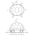
図示例の玩具(符号省略)は生物、具体的にはカメ(亀)を模したものであり、当該玩具は、歩行等のために頭部等が出っ張った第1形態(図1を参照)と、防御等のために頭部等が第1形態よりも引っ込んだ第2形態(図2を参照)とに変化可能である。 The toy (reference numerals omitted) in the illustrated example imitates a living creature, specifically a turtle (tortoise), and the toy is in a first form with a protruding head and the like for walking (see FIG. 1). and a second form (see FIG. 2) in which the head and the like are retracted more than the first form for defense and the like.

また、玩具は、主として、主体部10と、主体部10に出入り可能に設けられた副体部(第1の副体部20、1対の第2の副体部30、1対の第3の副体部40および第4の副体部50)とを備え、当該副体部は、第1形態において主体部10から出っ張った態様(図1を参照)を成し、第2形態において第1形態よりも引っ込んだ態様(図2を参照)を成すように構成されている。 In addition, the toy mainly consists of the main body 10 and the sub-body parts (first sub-body 20, a pair of second sub-body parts 30, a pair of third sub-body parts 30, and a pair of sub-body parts 30) provided so as to be able to enter and exit the main body part 10. The secondary body portion 40 and the fourth secondary body portion 50), and the secondary body portion protrudes from the main body portion 10 in the first form (see FIG. 1), and in the second form, the second It is configured to have a more retracted form (see FIG. 2) than one form.

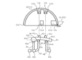
さらに、主体部10内には、前記副体部のうちの第1の副体部20、1対の第2の副体部30および1対の第3の副体部40(第4の副体部50を除く)の出入りを制御する出入り制御部60(図3および図4を参照)が設けられている。 Further, in the main body 10, among the sub-body parts, there are a first sub-body part 20, a pair of second sub-body parts 30 and a pair of third sub-body parts 40 (fourth sub-body part). An entry/exit control section 60 (see FIGS. 3 and 4) is provided for controlling entry and exit of the body portion 50 (excluding the body portion 50).

〈主体部10と第4の副体部50の具体構成〉
図1~図4から分かるように、主体部10は全体が丸みを帯びており、当該主体部10は、椀状の第1主体要素11と、第1主体要素11よりも高さ(上下方向寸法)が小さな椀状の第2主体要素12とを含む。また、主体部10は、第1主体要素11と第2主体要素12が各々の開口側が向き合った状態で着脱可能に連結されている。ここでの「第1主体要素11の開口側」は図3に示した第1主体要素11の下端開口側を指し、「第2主体要素12の開口側」は図4に示した第2主体要素12の上端開口側を指す。さらに、第1主体要素11の開口側の外郭は、第2主体要素12の開口側の外郭よりも大きい。
<Specific configuration of the main body portion 10 and the fourth sub-body portion 50>
As can be seen from FIGS. 1 to 4, the main body portion 10 has a rounded shape as a whole. and a bowl-shaped second main body element 12 of small size. Further, the main body part 10 is detachably connected to the first main body element 11 and the second main body element 12 with their opening sides facing each other. Here, the "opening side of the first main element 11" refers to the lower opening side of the first main element 11 shown in FIG. 3, and the "opening side of the second main element 12" refers to the second main element shown in It refers to the top open side of element 12 . Furthermore, the opening-side contour of the first main body element 11 is larger than the opening-side contour of the second main body element 12 .

図3および図4から分かるように、第1主体要素11の内面下部の周囲には、第2主体要素12に設けられた4個の円柱状の連結部12dそれぞれを着脱可能に嵌め込むことができる円柱状の凹部11a1を具備した4個の円柱状の連結部11aが設けられている。また、第1主体要素11の内面上部には、出入り制御部60の支持部61に設けられた2個の円柱状の主連結部61aそれぞれを着脱可能に嵌め込むことができる円柱状の凹部11b1を具備した2個の円柱状の連結部11bが設けられている。さらに、第1主体要素11の下面後部には、第4の副体部50に設けられた円柱状の連結部51を着脱可能に、かつ、回転可能に嵌め込むことができる円柱状の凹部11cが設けられている。さらに、第1主体要素11の下面前部には、第1の副体部20に対応した窪み部11dが設けられている。 As can be seen from FIGS. 3 and 4, the four cylindrical connecting portions 12d provided on the second main element 12 can be detachably fitted around the lower inner surface of the first main element 11. There are provided four cylindrical connecting portions 11a with cylindrical recesses 11a1 that can be formed. In addition, in the upper part of the inner surface of the first main element 11, there is a cylindrical concave portion 11b1 into which each of the two cylindrical main connecting portions 61a provided on the support portion 61 of the entrance/exit control portion 60 can be detachably fitted. There are provided two cylindrical connecting portions 11b. Furthermore, in the rear part of the lower surface of the first main element 11, a columnar recess 11c into which a columnar connecting portion 51 provided on the fourth subbody portion 50 can be detachably and rotatably fitted. is provided. Further, a recess portion 11 d corresponding to the first sub-body portion 20 is provided on the front portion of the lower surface of the first main element 11 .

なお、前記連結部11aおよび前記連結部12dの数は4個未満であってもよいし、4個超過であってもよい。また、前記連結部11bおよび前記主連結部61aの数は1個であってもよいし、2個超過であってもよい。さらに、前記窪み部11dは第1の副体部20の外形に応じて排除してもよい。 The number of the connecting portions 11a and the connecting portions 12d may be less than four or may be more than four. Further, the number of the connecting portion 11b and the main connecting portion 61a may be one or more than two. Furthermore, the recessed portion 11d may be eliminated according to the outer shape of the first subbody portion 20. As shown in FIG.

図4から分かるように、第2主体要素12の上面から側面には、第1の副体部20と各第2の副体部30と各第3の副体部40のそれぞれに対応した側面視が略U状の出入り部12aと左右1対の出入り部12bと左右1対の出入り部12cが設けられている。各出入り部12a、12bおよび12cは、第1主体要素11と第2主体要素12とが連結された状態で、第1の副体部20と各第2の副体部30と各第3の副体部40の出入りを可能とした孔(以下、この孔を出入り部とも言う)と成り得る。 As can be seen from FIG. 4, from the top surface to the side surface of the second main element 12, there are side surfaces corresponding to the first sub-body portion 20, each second sub-body portion 30, and each third sub-body portion 40, respectively. A substantially U-shaped entrance/exit portion 12a, a pair of right and left entrance/exit portions 12b, and a pair of left and right entrance/exit portions 12c are provided. Each of the entrance/exit portions 12a, 12b, and 12c includes the first sub-body portion 20, the second sub-body portion 30, and the third sub-body portion 30 in a state in which the first main element 11 and the second main element 12 are connected. It can be a hole that allows entry and exit of the secondary body portion 40 (hereinafter, this hole is also referred to as an entry and exit portion).

また、第2主体要素12の内面上部の周囲には、前記4個の円柱状の連結部12dが設けられている。さらに、第2主体要素12の下面には、第1形態および第2形態において玩具載置面(符号省略、図1(B)および図2(B)の2点鎖線を参照)と向き合う平坦部12eが設けられている。ここでの「玩具載置面」は、第1形態において各第2の副体部30と各第3の副体部40が接する面を指し、第2形態において主体部10の第2主体要素12の平坦部12eが接する面を指す。 Also, around the upper inner surface of the second main element 12, the four cylindrical connecting portions 12d are provided. Further, on the lower surface of the second main element 12, a flat portion facing the toy placing surface (reference numerals omitted, see two-dot chain lines in FIGS. 1(B) and 2(B)) in the first and second configurations 12e is provided. Here, the "toy placement surface" refers to the surface where each second sub-body portion 30 and each third sub-body portion 40 contact in the first form, and the second main element of the main body part 10 in the second form. It refers to the surface with which the flat portion 12e of 12 is in contact.

ちなみに、図示例の玩具はカメを模したものであるため、主体部10の第1主体要素11はカメの背甲部に相当し、主体部10の第2主体要素12はカメの腹甲部に相当し、第1の副体部20はカメの頭部に相当し、各第2の副体部30はカメの各前肢部に相当し、各第3の副体部40はカメの各後肢部に相当し、第4の副体部50はカメの尾部に相当する。 Incidentally, since the illustrated toy is modeled after a turtle, the first main element 11 of the main body 10 corresponds to the dorsal part of the turtle, and the second main element 12 of the main body 10 corresponds to the plastron of the turtle. , a first subbody 20 corresponding to the turtle's head, each second subbody 30 corresponding to each turtle's forelimb, and each third subbody 40 corresponding to each turtle's head. Corresponding to the hind legs, the fourth subbody 50 corresponds to the tail of the turtle.

〈出入り制御部60の具体構成〉
図3および図4から分かるように、出入り制御部60は、円柱状または角柱状の支持部61と、当該支持部61に揺動可能に設けられた、第1の副体部20対応の第1揺動部62と、各第2の副体部30対応の第2揺動部63と、各第3の副体部40対応の第3揺動部64とを備えている。
<Specific Configuration of Access Control Unit 60>
As can be seen from FIGS. 3 and 4, the entry/exit control section 60 includes a columnar or prismatic support section 61 and a first subbody section 20 corresponding to the first subbody section 20 provided swingably on the support section 61 . 1 rocking portion 62 , second rocking portion 63 corresponding to each second sub body portion 30 , and third rocking portion 64 corresponding to each third sub body portion 40 .

支持部61の上面には、前記2個の円柱状の主連結部61aが設けられている。また、支持部61の前端には、第1揺動部62対応の球状の第1連結部61bが設けられている。さらに、支持部61の下面には、第2揺動部63対応の縦断面C状の第2連結部61cと、第3揺動部64対応の縦断面C状の第3連結部61dが設けられている。 The upper surface of the supporting portion 61 is provided with the two cylindrical main connecting portions 61a. A spherical first connecting portion 61 b corresponding to the first swinging portion 62 is provided at the front end of the support portion 61 . Further, on the lower surface of the support portion 61, a second connecting portion 61c having a C-shaped longitudinal section corresponding to the second swinging portion 63 and a third connecting portion 61d corresponding to the third swinging portion 64 having a C-shaped longitudinal section are provided. It is

第1揺動部62は略L状または略S状に湾曲または屈曲した弾性変形可能な棒材から成り、上端に球状の連結部62aを有し、下端に球状の連結部62bを有している。第1揺動部62の上端の球状の連結部62aは、支持部61の第1連結部61bに設けられた半球よりも大きな球欠状の凹部61b1に回転可能に、好ましくは着脱可能に連結されており、主として前後方向の揺動を可能としている。 The first swinging portion 62 is made of an elastically deformable bar that is curved or bent in a substantially L-shape or substantially S-shape, and has a spherical connecting portion 62a at its upper end and a spherical connecting portion 62b at its lower end. there is A spherical connecting portion 62a at the upper end of the first swinging portion 62 is rotatably, preferably detachably, connected to a spherical recess 61b1 larger than a hemisphere provided in the first connecting portion 61b of the support portion 61. It is designed to allow rocking mainly in the front-rear direction.

第2揺動部63は略Ω状に湾曲または屈曲した弾性変形可能な棒材から成り、上部に円柱状の連結部63aを有し、両下端に球状の連結部63bを有している。第2揺動部63の上部の円柱状の連結部63aは、支持部61の第2連結部61cの縦断面C状の凹部61c1に回転可能に、好ましくは着脱可能に連結されており、主として前後方向の揺動を可能としている。 The second swinging portion 63 is made of an elastically deformable bar that is curved or bent in a substantially Ω shape, and has a columnar connecting portion 63a at its upper portion and spherical connecting portions 63b at both lower ends. The upper columnar connecting portion 63a of the second swinging portion 63 is connected rotatably, preferably detachably, to the concave portion 61c1 of the second connecting portion 61c of the support portion 61, which has a C-shaped longitudinal section. Allows fore-and-aft movement.

第3揺動部64は略Ω状に湾曲または屈曲した弾性変形可能な棒材から成り、上部に円柱状の連結部64aを有し、両下端に球状の連結部64bを有している。第3揺動部64の上部の円柱状の連結部64aは、支持部61の第3連結部61dの縦断面C状の凹部61d1に回転可能に、好ましくは着脱可能に連結されており、主として前後方向の揺動を可能としている。 The third oscillating portion 64 is made of an elastically deformable bar that is curved or bent in a substantially Ω shape, and has a columnar connecting portion 64a at its upper portion and a spherical connecting portion 64b at both lower ends. The upper columnar connecting portion 64a of the third swinging portion 64 is connected rotatably, preferably detachably, to the concave portion 61d1 of the third connecting portion 61d of the support portion 61, which has a C-shaped longitudinal section. Allows fore-and-aft movement.

〈第1の副体部20と各第2の副体部30と各第2の副体部40の具体構成〉
図4および図5から分かるように、第1の副体部20の後部には半球よりも大きな球欠状の凹部20aが設けられ、当該凹部20aは、出入り制御部60の第1揺動部62の下端の球状の連結部62bに回転可能に、好ましくは着脱可能に連結されている。
<Specific configuration of the first sub-body portion 20, each second sub-body portion 30, and each second sub-body portion 40>
As can be seen from FIGS. 4 and 5, the rear portion of the first secondary body portion 20 is provided with a spherical recess 20a larger than a hemisphere. 62 is rotatably, preferably detachably, connected to a spherical connecting portion 62b at the lower end thereof.

各第2の副体部30は、第1副体要素31と、当該第1副体要素31に回転可能に連結された第2副体要素32とを備えている。第1副体要素31の後部には半球よりも大きな球欠状の凹部31aが設けられ、当該凹部31aは、出入り制御部60の第2揺動部63の両下端の球状の連結部63bに回転可能に、好ましくは着脱可能に連結されている。また、第2副体要素32は球状の連結部32aを外面に有し、当該連結部32aは、第1副体要素31の前側の凹曲面31bに設けられた半球よりも大きな球欠状の凹部31cに回転可能に、好ましくは着脱可能に連結されている。 Each second sub-body 30 comprises a first sub-body element 31 and a second sub-body element 32 rotatably connected to the first sub-body element 31 . A spherical recess 31 a larger than a hemisphere is provided in the rear part of the first sub-body element 31 . It is rotatably, preferably detachably, connected. In addition, the second sub-body element 32 has a spherical connecting portion 32a on its outer surface, and the connecting portion 32a is a segmented spherical portion larger than the hemisphere provided on the front concave curved surface 31b of the first sub-body element 31. It is rotatably, preferably detachably, connected to the recess 31c.

各第3の副体部40は、第1副体要素41と、当該第1副体要素41に回転可能に連結された第2副体要素42とを備えている。第1副体要素41の前部には半球よりも大きな球欠状の凹部41aが設けられ、当該凹部41aは、出入り制御部60の第3揺動部64の両下端の球状の連結部64bに回転可能に、好ましくは着脱可能に連結されている。また、第2副体要素42は球状の連結部42aを外面に有し、当該連結部42aは、第1副体要素41の後側の凹曲面41bに設けられた半球よりも大きな球欠状の凹部41cに回転可能に、好ましくは着脱可能に連結されている。 Each third sub-body 40 comprises a first sub-body element 41 and a second sub-body element 42 rotatably connected to the first sub-body element 41 . The front portion of the first sub-body element 41 is provided with a spherical recess 41 a larger than a hemisphere. is rotatably, preferably detachably, connected to the In addition, the second sub-body element 42 has a spherical connecting portion 42a on its outer surface, and the connecting portion 42a has a spherical segment shape larger than the hemisphere provided on the concave curved surface 41b on the rear side of the first sub-body element 41. is rotatably, preferably detachably, connected to the recess 41c.

〈玩具の組み立て方法例〉
前述の玩具の構成をより明らかとするために、玩具構成部品全てが分解されている状態を開始点として、当該玩具の組み立て方法の一例を紹介する。
<Example of how to assemble a toy>
In order to better clarify the configuration of the aforementioned toy, an example of how to assemble the toy will be introduced, starting with all of the toy components disassembled.

まず、支持部61の第1連結部61bの凹部61b1に第1揺動部62の上端の連結部62aを嵌め込み、支持部61の第2連結部61cの凹部61c1に第2揺動部63の上部の連結部63aを嵌め込み、支持部61の第3連結部61dの凹部61d1に第3揺動部64の上部の連結部64aを嵌め込んで、支持部61と第1揺動部62と第2揺動部63と第3揺動部64とを備えた出入り制御部60を組み立てる(図3および図4を参照)。 First, the connecting portion 62a at the upper end of the first swinging portion 62 is fitted into the concave portion 61b1 of the first connecting portion 61b of the supporting portion 61, and the second swinging portion 63 is inserted into the concave portion 61c1 of the second connecting portion 61c of the supporting portion 61. The upper connecting portion 63a is fitted, and the upper connecting portion 64a of the third swinging portion 64 is fitted into the concave portion 61d1 of the third connecting portion 61d of the supporting portion 61, so that the supporting portion 61, the first swinging portion 62 and the third swinging portion 64 are connected. Assemble the entry/exit control section 60 including the second swing section 63 and the third swing section 64 (see FIGS. 3 and 4).

また、第1副体要素31の前側の凹部31cに第2副体要素32の外面の連結部32aを嵌め込んで、第1副体要素31と第2副体要素32とを備えた各第2の副体部30を組み立てる(図5(B)を参照)。 In addition, each sub-body element comprising the first sub-body element 31 and the second sub-body element 32 is fitted with the connecting portion 32a on the outer surface of the second sub-body element 32 in the recess 31c on the front side of the first sub-body element 31. 2 subbody parts 30 are assembled (see FIG. 5(B)).

さらに、第1副体要素41の後側の凹部41cに第2副体要素42の外面の連結部42aを嵌め込んで、第1副体要素41と第2副体要素42を備えた各第3の副体部40を組み立てる(図5(C)を参照)。 Further, the connecting portion 42a on the outer surface of the second sub-body element 42 is fitted into the recess 41c on the rear side of the first sub-body element 41, so that each sub-body element 41 and the second sub-body element 42 are provided. Assemble the secondary body 40 of No. 3 (see FIG. 5(C)).

そして、出入り制御部60の第1揺動部62の下端の連結部62bを第1の副体部20の後部の凹部20aに嵌め込み、第2揺動部63の両下端の連結部63bを第2の副体部30の第1副体要素31の後部の凹部31aにそれぞれ嵌め込み、第3揺動部64の両下端の連結部64bを第3の副体部40の第1副体要素41の前部の凹部41aにそれぞれ嵌め込んで、出入り制御部60に各副体部20、30および40を取り付けた第1組み立て物を作製する(図4および図5を参照)。 Then, the connecting portion 62b at the lower end of the first swinging portion 62 of the entrance/exit control portion 60 is fitted into the concave portion 20a at the rear portion of the first subbody portion 20, and the connecting portions 63b at both lower ends of the second swinging portion 63 are inserted into the second swinging portion 63. The first sub-body element 31 of the sub-body part 30 of No. 2 is fitted into the recessed part 31 a at the rear part of the first sub-body element 31 of the sub-body part 30 of No. 2, and the connecting parts 64 b at both lower ends of the third swing part 64 are connected to the first sub-body element 41 of the third sub-body part 40 . A first assembly is prepared by attaching each of the sub-body parts 20, 30 and 40 to the entry/exit control part 60 (see FIGS. 4 and 5).

そして、第1組み立て物における支持部61の上面の各主連結部61aを、主体部10の第1主体要素11の内面上部の各連結部11bの凹部11b1に嵌め込むとともに、第4の副体部50の連結部51を第1主体要素11の下面後部の凹部11cに嵌め込んで、第1組み立て物および第4の副体部50を主体部10の第1主体要素11に取り付けた第2組み立て物を作製する。 Then, each main connection portion 61a on the upper surface of the support portion 61 in the first assembly is fitted into the concave portion 11b1 of each connection portion 11b on the upper inner surface of the first main element 11 of the main body 10, and the fourth secondary body The connecting part 51 of the part 50 is fitted into the recess 11c in the lower rear part of the first main body element 11 to attach the first assembly and the fourth sub-body part 50 to the first main body element 11 of the main body part 10 . Create an assembly.

そして、主体部10の第2主体要素12の出入り部12a、12bおよび12cに第2組み立て物における第1の副体部20と各第2の副体部30と各第3の副体部40がそれぞれ入り込ようにしながら、当該第2主体要素12の内面上部の周囲の各連結部12dを、第2組み立て物における主体部10の第1主体要素11の内面下部の各連結部11aの凹部11a1に嵌め込んで、第2組み立て物の主体部10の第1主体要素11に第2主体要素12が取り付けられた所期の玩具(図1および図2を参照)を作製する。 Then, the first sub-body portion 20, each second sub-body portion 30 and each third sub-body portion 40 in the second assembly are attached to the entrance/exit portions 12a, 12b and 12c of the second main element 12 of the main body portion 10. while inserting each connecting portion 12d around the upper inner surface of the second main element 12 into the recess of each connecting portion 11a at the lower inner surface of the first main element 11 of the main body 10 in the second assembly 11a1 to produce the intended toy (see FIGS. 1 and 2) with the second main body element 12 attached to the first main body element 11 of the main body 10 of the second assembly.

〈玩具の第1形態から第2形態への変化〉
前述の玩具を第1形態(図1を参照)から第2形態(図2を参照)に変化させるときには、第1の副体部20を指先で押し込んで出入り部12aに沿って引っ込ませ、第1副体要素31と第2副体要素32を適宜回転させて向きを調整してから各第2の副体部30を指先で押し込んで各出入り部12bに沿って引っ込ませ、第1副体要素41と第2副体要素42を適宜回転させて向きを調整してから各第3の副体部40を指先で押し込んで各出入り部12cに沿って引っ込ませるとともに、第4の副体部50を指先で適宜回転させて向きを調整する。
<Change from the first form of the toy to the second form>
When changing the aforementioned toy from the first configuration (see FIG. 1) to the second configuration (see FIG. 2), the first sub-body portion 20 is pushed in with a fingertip to retract along the access portion 12a, and the second sub-body portion 20 is retracted along the access portion 12a. After adjusting the orientation by appropriately rotating the first sub-body element 31 and the second sub-body element 32, each second sub-body part 30 is pushed in with a fingertip to retract along each entrance/exit part 12b, and the first sub-body element After appropriately rotating the element 41 and the second sub-body element 42 to adjust their orientation, each third sub-body part 40 is pushed in with a fingertip to retract along each entrance/exit part 12c, and the fourth sub-body part is retracted. Rotate 50 appropriately with a fingertip to adjust the orientation.

ちなみに、各第2の副体部30は出入り制御部60の第2揺動部63に連結され、各第3の副体部40は出入り制御部60の第3揺動部64に連結されているため、一方の第2の副体部30を指先で押し込むことにより他方の第2の副体部30をある程度引っ込ませることが可能であり、また、一方の第3の副体部40を指先で押し込むことにより他方の第3の副体部40をある程度引っ込ませることが可能である。よって、このような押し込み方法を行った後に引っ込み不足を生じている方を指先で押し込んで引っ込み量を調整してもよい。 Incidentally, each second sub-body portion 30 is connected to the second swinging portion 63 of the entrance/exit control portion 60, and each third sub-body portion 40 is connected to the third swing portion 64 of the entrance/exit control portion 60. Therefore, by pushing one of the second sub-body portions 30 with a fingertip, the other second sub-body portion 30 can be retracted to some extent, and the one third sub-body portion 40 can be pushed with a fingertip. It is possible to retract the other third subbody portion 40 to some extent by pushing it in. Therefore, after performing such a pushing-in method, it is possible to adjust the amount of withdrawal by pushing in the side with insufficient withdrawal with a fingertip.

前述の玩具は、主体部10の第1主体要素11の開口側の外郭が第2主体要素12の開口側の外郭よりも大きいために両者の境界部分には段差(符号省略)があり、図2から分かるように、第2形態にあっては第1の副体部20の端部と各第2の副体部30の端部(第2副体要素32の端部)と各第3の副体部40の端部(第2副体要素42の端部)が当該段差に位置する。換言すれば、前述の玩具を第2形態(図2を参照)から第1形態(図1を参照)からに変化させるときに、第1の副体部20と各第2の副体部30と各第3の副体部40を引っ張り出す必要があるため、当該引っ張り出しに必要な最小限部分が第2主体要素12の外面から外に出ている。一方、第4の副体部50は前記段差よりも上面視幅が小さい場合、当該段差に隠れるような態様となる。 In the toy described above, since the outline of the main body 10 on the opening side of the first main element 11 is larger than the outline of the second main element 12 on the opening side, there is a step (reference numerals omitted) at the boundary between the two. 2, in the second form, the end of the first sub-body 20, the end of each second sub-body 30 (the end of the second sub-body element 32) and each third The end of the secondary body portion 40 (the end of the second secondary body element 42) is positioned at the step. In other words, when changing the aforementioned toy from the second configuration (see FIG. 2) to the first configuration (see FIG. 1), the first sub-body 20 and each second sub-body 30 and each third subbody 40 must be pulled out, so that the minimum required for such pulling out is outside the outer surface of the second main body element 12 . On the other hand, when the width in top view of the fourth sub-body portion 50 is smaller than the step, the fourth sub-body portion 50 is hidden by the step.

なお、図2(A)には上から見たときに各第2の副体部30の端部(第2副体要素32の端部)と各第3の副体部40の端部(第2副体要素42の端部)が主体部10の第1主体要素11よりも外に少し出ているものを描いているが、各第2の副体部30の端部と各第3の副体部40の端部は、第4の副体部50と同様に前記段差に隠れるような態様となっていてもよい。 2(A) shows an end portion of each second sub-body portion 30 (end portion of the second sub-body element 32) and an end portion of each third sub-body portion 40 (end portion of the second sub-body element 32) when viewed from above. , the ends of the second sub-body elements 42) protrude slightly beyond the first main element 11 of the main body 10, but the ends of each second sub-body 30 and each third The end portion of the second sub-body portion 40 may be hidden by the step as in the case of the fourth sub-body portion 50 .

第2形態(図2を参照)において第1の副体部20と各第2の副体部30と各第3の副体部40の引っ張り出しに必要な最小限部分が第2主体要素12の外面から外に出るようにするには、第1の副体部20と各第2の副体部30と各第3の副体部40のそれぞれの引っ込み量を制限することが望ましい。 In the second configuration (see FIG. 2), the second main body element 12 is the minimum required for pulling out the first sub-body 20, each second sub-body 30, and each third sub-body 40. It is desirable to limit the amount of retraction of each of the first sub-body 20 and each second sub-body 30 and each third sub-body 40 to exit from the outer surface of the .

前記引っ込み量の制限手法としては、(M11)第1の副体部20の前側部分の外形を出入り部12aよりも大きくし、各第2の副体部30の第2副体要素32の前側部分の外形を出入り部12bよりも大きくし、各第3の副体部40の第2副体要素42の後側部分の外形を出入り部12cよりも大きくする手法、(M12)出入り制御部60の第1揺動部62と第2揺動部63と第3揺動部64の揺動可能な角度範囲を突起等によって制限する手法、等が好ましく採用できる。 As a method for limiting the amount of retraction, (M11) the outer shape of the front portion of the first sub-body portion 20 is made larger than that of the entrance/exit portion 12a, and the front side of the second sub-body element 32 of each second sub-body portion 30 is (M12) Access Control Unit 60 A method of limiting the swingable angular range of the first swinging portion 62, the second swinging portion 63, and the third swinging portion 64 by projections or the like can be preferably employed.

〈玩具の第2形態から第1形態への変化〉
前述の玩具を第2形態(図2を参照)から第1形態(図1を参照)に変化させるときには、第1の副体部20の端部を指先で摘まんで出入り部12aに沿って引っ張り出し、各第2の副体部30を端部を指先で摘まんで各出入り部12bに沿って引っ張り出して各第1副体要素31と各第2副体要素32を適宜回転させて向きを調整し、各第3の副体部40の端部を指先で摘まんで各出入り部12cに沿って引っ張り出して各第1副体要素41と各第2副体要素42を適宜回転させて向きを調整するとともに、第4の副体部50を指先で適宜回転させて向きを調整する。
<Change from the second form of the toy to the first form>
When changing the aforementioned toy from the second configuration (see FIG. 2) to the first configuration (see FIG. 1), the end of the first sub-body portion 20 is picked up with the fingertips and pulled along the entrance/exit portion 12a. The ends of the second sub-body portions 30 are pinched with the fingertips and pulled out along the entrance/exit portions 12b. Then, pinch the end of each third sub-body portion 40 with your fingertips and pull it out along each entrance/exit portion 12c so that each first sub-body element 41 and each second sub-body element 42 are rotated and oriented as appropriate. is adjusted, and the orientation is adjusted by appropriately rotating the fourth subbody portion 50 with a fingertip.

ちなみに、各第2の副体部30は出入り制御部60の第2揺動部63に連結され、各第3の副体部40は出入り制御部60の第3揺動部64に連結されているため、一方の第2の副体部30の端部を指先で摘まんで引っ張り出すことにより他方の第2の副体部30をある程度引っ張り出すことが可能であり、また、一方の第3の副体部40の端部を指先で摘まんで引っ張り出すことにより他方の第3の副体部40をある程度引っ張り出すことが可能である。よって、このような引っ張り出し方法を行った後に出っ張り不足を生じている方を指先で引っ張り出して出っ張り量を調整してもよい。 Incidentally, each second sub-body portion 30 is connected to the second swinging portion 63 of the entrance/exit control portion 60, and each third sub-body portion 40 is connected to the third swing portion 64 of the entrance/exit control portion 60. Therefore, it is possible to pull out the other second sub-body portion 30 to some extent by pinching the end portion of one of the second sub-body portions 30 with the fingertips and pulling it out. It is possible to pull out the other third sub-body 40 to some extent by pinching the end of the sub-body 40 with the fingertips and pulling it out. Therefore, after performing such a pulling-out method, the side with insufficient protrusion may be pulled out with a fingertip to adjust the amount of protrusion.

図4から分かるように、前述の玩具は、出入り制御部60の第2揺動部63の揺動方向は各第2の副体部30の引っ張り出し方向と一致している訳ではなく、第3揺動部64の揺動方向も各第3の副体部40の引っ張り出し方向と一致している訳ではない。そのため、各第2の副体部30を引っ張り出すときには第2揺動部63の主として連結部63aを除く部分が上下方向および左右方向に弾性変形し、各第3の副体部40を引っ張り出すときには第3揺動部64の主として連結部64aを除く部分が上下方向および左右方向に弾性変形する。無論、第1の副体部20を引っ張り出すときには第1揺動部62の主として連結部62aを除く部分が上下方向に弾性変形する。 As can be seen from FIG. 4, in the toy described above, the direction of swinging of the second swinging portion 63 of the entrance/exit control portion 60 does not match the direction of pulling out each of the second sub-body portions 30. The swinging direction of the three swinging portions 64 does not coincide with the pulling-out direction of each of the third sub-body portions 40, either. Therefore, when each second sub-body portion 30 is pulled out, the portion of the second swinging portion 63 mainly except for the connecting portion 63a is elastically deformed in the vertical direction and the left-right direction, and each third sub-body portion 40 is pulled out. In some cases, the portion of the third swinging portion 64 except mainly the connecting portion 64a is elastically deformed vertically and horizontally. Of course, when the first secondary body portion 20 is pulled out, the portion of the first swinging portion 62 mainly excluding the connecting portion 62a is elastically deformed in the vertical direction.

すなわち、第2揺動部63の上下方向および左右方向の弾性変形に伴って各第2の副体部30の外面が各出入り部12bの内面(第1主体要素11の下面を含む)に接触し、第3揺動部64の上下方向および左右方向の弾性変形に伴って各第3の副体部40の外面が各出入り部12cの内面(第1主体要素11の下面を含む)に接触する。無論、第1揺動部62の上下方向に弾性変形に伴って第1の副体部20の外面が出入り部12aの内面(第1主体要素11の下面を含む)に接触する。つまり、第1の副体部20と各第2の副体部30と各第3の副体部40を引っ張り出すときには、前記接触の抵抗によって、各副体部20、30および40を任意の引っ張り出し位置で保持することも可能である。 That is, the outer surface of each second sub-body portion 30 comes into contact with the inner surface of each entrance/exit portion 12b (including the lower surface of the first main element 11) as the second rocking portion 63 is elastically deformed in the vertical and horizontal directions. Then, as the third rocking portion 64 elastically deforms in the vertical and horizontal directions, the outer surface of each third sub-body portion 40 comes into contact with the inner surface of each entrance/exit portion 12c (including the lower surface of the first main element 11). do. Of course, the outer surface of the first sub-body portion 20 comes into contact with the inner surface of the entrance/exit portion 12a (including the lower surface of the first main element 11) as the first rocking portion 62 elastically deforms in the vertical direction. In other words, when the first sub-body 20, the second sub-body 30 and the third sub-body 40 are pulled out, the sub-body 20, 30 and 40 are pulled out in any desired manner due to the contact resistance. It is also possible to hold it in the extended position.

これとは別に、第1形態(図1を参照)において第1の副体部20と各第2の副体部30と各第3の副体部40を最大量で引っ張り出すには、第1の副体部20と各第2の副体部30と各第3の副体部40のそれぞれの出っ張り量を制限することが望ましい。 Alternatively, in order to extract the first subbody 20, each second subbody 30 and each third subbody 40 by the maximum amount in the first configuration (see FIG. 1), the It is desirable to limit the amount of protrusion of each of the one subbody 20 and each second subbody 30 and each third subbody 40 .

前記出っ張り量の制限方法としては、(M21)第1の副体部20の後側部分の外形を出入り部12aよりも大きくし、各第2の副体部30の第1副体要素31の後側部分の外形を出入り部12bよりも大きくし、各第3の副体部40の第1副体要素41の前側部分の外形を出入り部12cよりも大きくする手法、(M22)第1の副体部20の後側部分に出入り部12aの内側に引っかかる部位を設け、各第2の副体部30の第1副体要素31の後側部分に出入り部12bの内側に引っかかる部位を設け、各第3の副体部40の第1副体要素41の前側部分に出入り部12cの内側に引っかかる部位を設ける手法、(M23)出入り制御部60の第1揺動部62と第2揺動部63と第3揺動部64の揺動可能な角度範囲を突起等によって制限する手法、等が好ましく採用できる。 As a method for limiting the amount of protrusion, (M21) the outer shape of the rear portion of the first sub-body portion 20 is made larger than that of the entrance/exit portion 12a, and the first sub-body element 31 of each second sub-body portion 30 is (M22) A method of making the outer shape of the rear portion larger than that of the entrance/exit portion 12b and making the outer shape of the front portion of the first sub-body element 41 of each third sub-body portion 40 larger than that of the entrance/exit portion 12c. The rear portion of the secondary body portion 20 is provided with a portion to be caught inside the entrance/exit portion 12a, and the rear portion of the first sub-body element 31 of each second subbody portion 30 is provided with a portion to be caught inside the entrance/exit portion 12b. (M23) A method of providing a portion to be caught inside the entrance/exit portion 12c in the front portion of the first sub-body element 41 of each third sub-body portion 40; A method of limiting the swingable angle range of the moving portion 63 and the third swinging portion 64 by a projection or the like can be preferably employed.

〈玩具によって得られる主たる作用効果〉
前述の玩具によれば、主体部10から副体部(第1の副体部20、各第2の副体部30、各第3の副体部40および第4の副体部50)が出っ張った第1形態(図1参照)と、当該副体部が第1形態よりも引っ込んだ第2形態(図2を参照)とに適宜変化させることができ、これより模倣対象(カメ)に相応の形態変化を可能として当該形態変化による興趣を遊戯者に供与することができる。
<Main functions and effects obtained by toys>
According to the aforementioned toy, from the main body 10, the sub-body parts (the first sub-body part 20, the second sub-body parts 30, the third sub-body parts 40 and the fourth sub-body part 50) It can be appropriately changed into a protruding first form (see FIG. 1) and a second form (see FIG. 2) in which the secondary body part is more recessed than the first form. It is possible to provide a game player with interest due to the corresponding form change by enabling the corresponding form change.

また、前述の玩具によれば、前記副体部のうちの第1の副体部20、各第2の副体部30および各第3の副体部40の出入りを制御する出入り制御部60を主体部10内に有しているため、当該出入り制御部60によって前記形態変化を的確に行うことができ、この点においてより一層の興趣を遊戯者に供与することができる。 Further, according to the aforementioned toy, the entry/exit control section 60 for controlling the entry/exit of the first sub-body portion 20, the second sub-body portions 30, and the third sub-body portions 40 out of the sub-body portions. is provided in the main body 10, the entry/exit control section 60 can accurately perform the above-mentioned form change, and in this respect, it is possible to provide the player with more interest.

さらに、前述の玩具によれば、主体部10から第2主体要素12を外しときに第1主体要素11内に位置する出入り制御部60を模倣対象(カメ)の骨格のように見せることができ、この点においてもより一層の興趣を遊戯者に供与することができる。 Furthermore, according to the aforementioned toy, when the second main element 12 is removed from the main body 10, the entry/exit control section 60 positioned inside the first main element 11 can be made to look like the skeleton of the object to be imitated (tortoise). Also in this respect, it is possible to provide the player with more interest.

さらに、前述の玩具によれば、主体部10の全体が丸みを帯びているため、第2形態(図2を参照)の全体または一部をフィルム等で包装した立体形状のものを物品搬出装置の搬出対象とすること、例えば、硬貨等を投入して販売可能な装置の商品とすることができる。 Furthermore, according to the above-mentioned toy, since the main body part 10 is entirely rounded, the second form (see FIG. 2), which is wholly or partly wrapped in a film or the like, has a three-dimensional shape. For example, it can be a product of a device that can be sold by inserting coins or the like.

《前述の玩具の変形例》
以下、図6~図9を用いて、前述の玩具の変形例について説明する。この説明では、便宜上、図1~図5を用いた先の説明と同様に前、後、左、右、上、下の向きを表記する。
<<Modified example of the aforementioned toy>>
Modifications of the aforementioned toy will be described below with reference to FIGS. 6 to 9. FIG. In this description, for the sake of convenience, front, rear, left, right, up, and down directions are indicated in the same manner as in the previous description using FIGS.

〈出入り制御部60の変形例〉
図6は前述の出入り制御部60の変形例(出入り制御部60’)を示す。この出入り制御部60’は、
・前述の出入り制御部60の支持部61から第2連結部61cと第3連結部61dを排除
し、その代わりとして、支持部61’の左右に縦断面円形の棒状部分から成る補助支持
部61eを設けた点(図6(A)を参照)
・前述の出入り制御部60の第2揺動部63および第3揺動部64から上端の球状の連結
部63aおよび64aを排除して、その代わりとして、上端にC状係合部63a’を
有する2本の第2揺動部63’と上端にC状係合部64a’を有する2本の第3揺動部
64’を用いるともに、各C状係合部63a’および64a’を各補助支持部61eに
回転可能に、好ましくは着脱可能に連結した点(図6(A)および図6(B)を参照)
において、前述の出入り制御部60と構成を異にする。
<Modified Example of Access Control Unit 60>
FIG. 6 shows a modification (entrance control unit 60') of the entrance control unit 60 described above. This entry/exit control unit 60'
・The second connecting portion 61c and the third connecting portion 61d are eliminated from the support portion 61 of the entry/exit control portion 60 described above, and instead, auxiliary support portions 61e consisting of bar-shaped portions with a circular vertical cross section are provided on the left and right sides of the support portion 61'. (See FIG. 6(A))
・The spherical connecting portions 63a and 64a at the upper ends of the second swinging portion 63 and the third swinging portion 64 of the entrance/exit control portion 60 are eliminated, and instead, a C-shaped engaging portion 63a' is provided at the upper end. Two second rocking portions 63' and two third rocking portions 64' having C-shaped engaging portions 64a' at their upper ends are used, and the C-shaped engaging portions 63a' and 64a' are respectively A point rotatably, preferably detachably, connected to the auxiliary support 61e (see FIGS. 6(A) and 6(B))
, the configuration is different from that of the entrance/exit control unit 60 described above.

この出入り制御部60’によれば、各第2の副体部30に専用の第2揺動部63’が対応し、各第3の副体部40に専用の第3揺動部64’が対応しているため、各第2の副体部30と各第3の副体部40を個別に出入りさせることができる。また、各第2の副体部30の引っ張り出し方向を極力一致するように各第2揺動部63’の揺動方向を変えることができ、各第3の副体部40の引っ張り出し方向を極力一致するように各第3揺動部64’の揺動方向を変えることができるため、各第2の副体部30と各第2の副体部40の引っ張り出しをスムースに行うことができる。 According to this entry/exit control section 60', each second sub-body 30 is associated with a dedicated second swinging section 63', and each third sub-body 40 is associated with a dedicated third swinging section 64'. correspond to each other, each second sub-body 30 and each third sub-body 40 can be individually moved in and out. Further, the swinging direction of each second swinging portion 63' can be changed so that the pulling-out direction of each second sub-body portion 30 matches as much as possible, and the pulling-out direction of each third sub-body portion 40 can be changed. Since the swinging direction of each third swinging portion 64' can be changed so as to match as much as possible, each second sub-body portion 30 and each second sub-body portion 40 can be pulled out smoothly. can be done.

なお、図6(A)への図示を省略したが、前述の出入り制御部60の支持部61から第1連結部61bを排除し、その代わりとして、支持部61’の前に縦断面円形の棒状部分から成る補助支持部61f(図6(D)を参照)を設け、第1揺動部62の上端の球状の連結部62aの代わりに上端にC状係合部62a’を有する第1揺動部62’(図6(D)を参照)を用いて、当該C状係合部62a’を前記補助支持部61fに回転可能に、好ましくは着脱可能に連結してもよい。 Although not shown in FIG. 6A, the first connecting portion 61b is removed from the support portion 61 of the entrance/exit control portion 60 described above, and instead, a circular vertical cross-sectional shape is provided in front of the support portion 61'. An auxiliary support portion 61f (see FIG. 6D) consisting of a rod-like portion is provided, and instead of the spherical connecting portion 62a at the upper end of the first swinging portion 62, a C-shaped engaging portion 62a' is provided at the upper end. The C-shaped engaging portion 62a' may be rotatably, preferably detachably, connected to the auxiliary support portion 61f using a rocking portion 62' (see FIG. 6(D)).

また、図6(A)~図6(D)に示したC状係合部63a’、64a’および62a’はリング状係合部に変えてもよい。さらに、C状係合部63a’、64a’および62a’を用いる場合には、これらをリング状係合部に変えた場合も同様に、各補助支持部61eに各第2揺動部63’と各第3の揺動部64’の位置を制限する凹凸を設け、補助支持部61fに第1揺動部62’の位置を制限する凹凸を設けてもよい。 Also, the C-shaped engaging portions 63a', 64a' and 62a' shown in FIGS. 6A to 6D may be replaced with ring-shaped engaging portions. Further, when the C-shaped engaging portions 63a', 64a' and 62a' are used, and when these are changed to ring-shaped engaging portions, similarly, each second swinging portion 63' is attached to each auxiliary support portion 61e. and third swinging portions 64' may be provided with protrusions and recesses for restricting the positions of the first swing portions 64', and the auxiliary support portion 61f may be provided with protrusions and recesses for restricting the positions of the first swing portions 62'.

さらに、支持部61’の左右に設けた補助支持部61eの形は図6(A)に示した形に制限されるものではなく、第2揺動部63’と第3揺動部64’に前記同様の揺動が得られる形であれば、他の形、例えば、補助支持部61eの前後方向の中間部分(第2揺動部63’と第3揺動部64’が連結されていない部分)を排除したような形等を採用してもよい。 Furthermore, the shape of the auxiliary support portions 61e provided on the left and right sides of the support portion 61' is not limited to the shape shown in FIG. However, if the same rocking motion as described above can be obtained, another shape may be used. It is also possible to adopt a shape or the like that eliminates the portion where there is no portion).

さらに、前述の出入り制御部60の支持部61から第2連結部61cと第3連結部61dの一方のみを排除して、排除した側のみに前記同様の補助支持部を設けるようにしてもよい。 Further, only one of the second connecting portion 61c and the third connecting portion 61d may be removed from the support portion 61 of the entrance/exit control portion 60, and the same auxiliary support portion may be provided only on the removed side. .

〈第1の副体部20と各第2の副体部30と各第3の副体部40の変形例〉
図7は前述の第1の副体部20と各第2の副体部30と各第3の副体部40の変形例(第1の副体部20’と各第2の副体部30’と各第3の副体部40’)を示す。この第1の副体部20’、各第2の副体部30’および各第3の副体部40’は、
・前述の第1の副体部20を、第1副体要素21と第2副体要素22とから成る第1の副
体部20’に変え、第1副体要素21の前側の凸曲面20bに半球よりも大きな球欠状
の凹部20cを設け、第2副体要素22の後側の凹曲面20dに設けた球状の連結部2
0eを当該凹部20cに回転可能に、好ましくは着脱可能に連結した点(図7(A)を
参照)
・前述の第2の副体部30を、その第1副体要素31を、第1部分31-1と第2部分31
-2とから成る第1副体要素31’とした第2の副体部30’に変え、第1部分31-1の
前側の斜めの凹曲面31dに半球よりも大きな球欠状の凹部31eを設け、第2部分3
1-2の後側の斜面31fに設けた球状の連結部31gを当該凹部31eに回転可能に、
好ましくは着脱可能に連結した点(図7(B)を参照)
・前述の第3の副体部40を、その第1副体要素41を、第1部分41-1と第2部分41
-2とから成る第1副体要素41’とした第3の副体部40’に変え、第1部分41-1の
後側の斜めの凹曲面41dに半球よりも大きな球欠状の凹部41eを設け、第2部分4
1-2の前側の斜面41fに設けた球状の連結部41gを当該凹部41eに回転可能に、
好ましくは着脱可能に連結した点(図7(C)を参照)
において、前述の第1の副体部20、各第2の副体部30および各第3の副体部40と構成を異にする。
<Modified Examples of First Subbody 20, Second Subbody 30, and Third Subbody 40>
FIG. 7 shows a modified example of the first sub-body portion 20, the second sub-body portions 30 and the third sub-body portions 40 (the first sub-body portion 20' and the second sub-body portions). 30' and each third subbody 40'). The first subbody 20', each second subbody 30' and each third subbody 40'
- The above-mentioned first sub-body portion 20 is changed to a first sub-body portion 20' consisting of a first sub-body element 21 and a second sub-body element 22, and the front convex surface of the first sub-body element 21 is changed. 20b is provided with a recessed portion 20c larger than a hemisphere, and a spherical connecting portion 2 provided on the concave curved surface 20d on the rear side of the second sub-body element 22.
0e is rotatably, preferably detachably connected to the recess 20c (see FIG. 7(A))
- The above-mentioned second sub-body part 30, its first sub-body element 31, the first part 31-1 and the second part 31
-2, and a spherical recess 31e larger than a hemisphere is formed on the oblique concave curved surface 31d on the front side of the first portion 31-1. is provided, and the second part 3
A spherical connecting portion 31g provided on the slope 31f on the rear side of 1-2 is rotatable to the recessed portion 31e,
Preferably detachably connected points (see FIG. 7(B))
- The above-mentioned third sub-body part 40, its first sub-body element 41, the first part 41-1 and the second part 41
-2, and a spherical recess larger than a hemisphere is formed on the oblique concave surface 41d on the rear side of the first portion 41-1. 41e is provided and the second part 4
A spherical connecting portion 41g provided on the slope 41f on the front side of 1-2 is rotatable to the concave portion 41e,
Preferably detachably connected points (see FIG. 7(C))
, the configuration is different from that of the first sub-body portion 20, the second sub-body portions 30 and the third sub-body portions 40 described above.

この第1の副体部20’によれば、第1形態(図1を参照)において第1副体要素21に対し第2副体要素22を回転させてその向きを任意に変えることができる。また、第2の副体部30’によれば、第1形態(図1を参照)において第1副体要素31’の第1部分31-1に対し第1部分31-2を回転させてその向きを任意に変えることができる。さらに、第3の副体部40’によれば、第1形態(図1を参照)において第1副体要素41’の第1部分41-1に対し第1部分41-2を回転させてその向きを任意に変えることができる。 According to this first sub-body portion 20', in the first configuration (see FIG. 1), the second sub-body element 22 can be rotated with respect to the first sub-body element 21 to arbitrarily change its orientation. . Also, according to the second subbody 30', in the first configuration (see FIG. 1), the first portion 31-2 is rotated with respect to the first portion 31-1 of the first subbody element 31'. You can change its direction arbitrarily. Further, according to the third subbody 40', in the first configuration (see FIG. 1) the first portion 41-2 is rotated with respect to the first portion 41-1 of the first subbody element 41'. You can change its direction arbitrarily.

すなわち、第1の副体部20’、各第2の副体部30’および各第3の副体部40’は、前述の第1の副体部20、各第2の副体部30および各第3の副体部40に比べて態様変化の自由度が高いため、特に第1形態(図1を参照)を模倣対象(カメ)により似せることができる。 That is, the first sub-body portion 20', each second sub-body portion 30' and each third sub-body portion 40' are similar to the first sub-body portion 20 and each second sub-body portion 30 described above. Since the degree of freedom in changing the form is higher than that of each third subbody part 40, the first form (see FIG. 1) in particular can be made to resemble the imitation target (tortoise).

また、各第2の副体部30’および各第3の副体部40’を用いた場合には、第2形態として図8のような態様、すなわち、各第2の副体部30’の第1副体要素31’の第2部分31-2と第2副体要素32と、各第3の副体部40’の第1副体要素41の第2部分41-2と第2副体要素42とが、前記段差に位置する態様とすることも可能となる。 In addition, when each second sub-body portion 30' and each third sub-body portion 40' are used, a mode as shown in FIG. second part 31-2 and second sub-body element 32 of first sub-body element 31' of each third sub-body part 40' and second part 41-2 and second sub-body element 41 of each third sub-body element 40' It is also possible to adopt an aspect in which the sub-body element 42 is positioned at the step.

すなわち、各第2の副体部30’にあっては、第2副体要素32の端部が第2主体要素12の外面から外に出た態様(図2を参照)と、第1副体要素31’の第2部分31-2と第2副体要素32が第2主体要素12の外面から外に出た態様(図8を参照)とを任意に選択でき、また、各第3の副体部40’にあっては、第2副体要素42の端部が第2主体要素12の外面から外に出た態様(図2を参照)と、第1副体要素41’の第2部分41-2と第2副体要素42が第2主体要素12の外面から外に出た態様(図8を参照)を任意に選択ができるため、第2形態のバリエーションを増すことができ、この点においてより一層の興趣を遊戯者に供与することができる。 That is, in each second sub-body portion 30', the end portion of the second sub-body element 32 protrudes from the outer surface of the second main body element 12 (see FIG. 2), and the first sub-body portion 30' The second portion 31-2 of the body element 31' and the manner in which the second sub-body element 32 protrudes from the outer surface of the second main body element 12 (see FIG. 8) can be arbitrarily selected. In the sub-body portion 40', the end portion of the second sub-body element 42 protrudes from the outer surface of the second main body element 12 (see FIG. 2), and the first sub-body element 41' Since the mode in which the second portion 41-2 and the second sub-body element 42 protrude from the outer surface of the second main body element 12 (see FIG. 8) can be arbitrarily selected, variations of the second form can be increased. In this respect, it is possible to provide the player with more interest.

〈丸み付け部品70〉
図9は前述の玩具に取り付け可能な丸み付け部品70を示す。この丸み付け部品70は、第2形態(図2および図8を参照)の全体または一部をフィルム等で包装した立体形状のものを物品搬出装置の搬出対象とするときに、第2形態を球形に近付けるためのものである。
<Rounding component 70>
FIG. 9 shows a rounded part 70 that can be attached to the aforementioned toy. This rounding part 70 is used when a three-dimensional object in which the second form (see FIGS. 2 and 8) is wholly or partly wrapped in a film or the like is to be carried out by the article carrying-out apparatus. This is for approximating a spherical shape.

丸み付け部品70は、平坦な上面と凸曲面から成る下面とを有する部品であり、平坦な上面には、前述の玩具の主体部10の第2主体要素12の下面に設けられた取り付け穴または孔(図示省略)に着脱可能に嵌め込むことができる角柱状の取り付け部71を有している。丸み付け部品70の平坦な上面の外郭は、第1主体要素11の開口側の外郭と同じかまたはそれよりも小さく、当該丸み付け部品70を第2形態(図2および図8を参照)における主体部10の第2主体要素12に取り付けると全体がより球形に近い立体形状となる。 The rounding part 70 is a part having a flat upper surface and a convexly curved lower surface. It has a prismatic mounting portion 71 that can be detachably fitted into a hole (not shown). The contour of the flat top surface of the rounding piece 70 is the same as or smaller than the contour of the opening side of the first main body element 11, so that the rounding piece 70 is in the second configuration (see FIGS. 2 and 8). When attached to the second main element 12 of the main body 10, the whole becomes a three-dimensional shape closer to a sphere.

すなわち、先に述べた物品搬出装置の仕様等が支障となって、第2形態(図2を参照)の全体または一部をフィルム等で包装した立体形状のものを搬出対象としたときに搬出不良等が生じる場合でも、前記丸み付け部品70を第2形態(図2および図8を参照)における主体部10の第2主体要素12に取り付ければ、搬出不良等を生じることなく搬出することが可能となる。 That is, when the specifications of the above-mentioned article carry-out device become a hindrance, and a three-dimensional object in which the whole or a part of the second form (see FIG. 2) is wrapped with a film or the like is targeted for carry-out. Even if a defect or the like occurs, if the rounding part 70 is attached to the second main element 12 of the main body 10 in the second form (see FIGS. 2 and 8), it can be carried out without causing a carry-out defect. It becomes possible.

〈その他の変形例〉
以下、前述の玩具の他の変形例について説明する。
(1)第4の副体部50を単独で回転できるものを例示したが、専用の出入り部を主体部10の第2主体要素12に設け、かつ、専用の揺動部を出入り制御部60に設けて、当該第4の副体部50を、第1の副体部20、各第2の副体部30および各第3の副体部40と同様、主体部10に出入り可能に構成してもよい。このようにすれば、第4の副体部50が大きい場合でもその出入りを的確に行うことができる。
<Other Modifications>
Other modifications of the toy described above will be described below.
(1) Although the fourth sub-body portion 50 is rotatable independently, a dedicated entrance/exit portion is provided in the second main element 12 of the main body portion 10, and a dedicated swing portion is provided in the entrance/exit control portion 60. , and the fourth sub-body portion 50 can be moved in and out of the main body portion 10 like the first sub-body portion 20, the second sub-body portions 30 and the third sub-body portions 40. You may In this way, even when the fourth sub-body portion 50 is large, it can be moved in and out accurately.

(2)第2主体要素12の上面から側面に出入り部12aと各出入り部12bと各出入り部12cとなる略U状部分を設け、これらを第1主体要素11の下面で閉じるようにしたものを例示したが、第1主体要素11の上面から側面に同様の略U状部分を設けて、第2主体要素12の略U状部分と第1主体要素11の略U状部分との組合せによって各出入り部を構成してもよい。 (2) The second main element 12 is provided with approximately U-shaped portions from the upper surface to the side thereof, which are the entrance/exit portion 12a, the entrance/exit portions 12b, and the entrance/exit portions 12c, and are closed by the lower surface of the first main element 11. However, by providing a similar substantially U-shaped portion from the upper surface to the side surface of the first main element 11 and combining the substantially U-shaped portion of the second main element 12 and the substantially U-shaped portion of the first main element 11 Each entrance/exit may be configured.

(3)主体部10の第2主体要素12として第1主体要素11よりも高さ(上下方向寸法)がかなり小さいものを例示したが、図示例よりも第1主体要素11の高さを小さくしてもよいし、図示例よりも第2主体要素12の高さを大きくしてもよい。ちなみに、図示例よりも第1主体要素11の高さを小さくすることによって主体部10の全体が丸みが低下することを原因として、先に述べた物品搬出装置において搬出不良等が生じる場合には、図9に例示した丸み付け部品と同様の部品、例えば、凸曲面から成る上面と凹曲面から成る下面を有する部品等を第1主体要素11の方に取り付けることができるようにして、当該部品の取り付けによって第2形態を球形に近付けるようにしてもよい。 (3) As the second main element 12 of the main body 10, the height (vertical dimension) is considerably smaller than that of the first main element 11, but the height of the first main element 11 is made smaller than in the illustrated example. Alternatively, the height of the second main body element 12 may be made larger than in the illustrated example. By the way, if the height of the first main element 11 is made smaller than in the illustrated example, the roundness of the main body 10 as a whole is reduced. , a part similar to the rounding part illustrated in FIG. 9, for example, a part having a convex curved upper surface and a concave curved lower surface, etc., can be attached to the first main element 11. The second form may be made to approximate a sphere by attaching the .

(4)第2形態(図2を参照)の全体または一部をフィルム等で包装した立体形状のものを物品搬出装置の搬出対象とするものを例示したが、主体部10内に他の分解部品全てを収容して、当該主体部10の全体または一部をフィルム等で包装したものを物品搬出装置の搬出対象としてもよい。このようにすれば、前記〈玩具の組み立て方法例〉で述べた組み立てと組み立て後の分解も可能となるため、組み立ておよび分解に係る興趣を興趣を供与することができる。 (4) In the second embodiment (see FIG. 2), a three-dimensional object in which the whole or part is wrapped with a film or the like is exemplified as an object to be carried out by the article carrying-out device. A product in which all the parts are contained and the whole or part of the main body 10 is wrapped with a film or the like may be used as an object to be carried out by the article carrying-out device. In this way, the assembly and disassembly after assembly described in <Example of Toy Assembly Method> can be performed, so that interest in assembly and disassembly can be provided.

(5)本発明を適用した玩具の一例としてカメを模したものを説明したが、主体部の形と副体部の形および数と出入り部の数および位置を変更することにより、頭部等の出入りに伴う形態変化を可能とした他の生物、例えば、頭足部を出入り可能なカタツムリや、頭部を出入り可能なサンヨウベニボタル等の生物を模倣対象とすることもできる。 (5) As an example of a toy to which the present invention is applied, a toy that imitates a turtle has been described, but by changing the shape of the main body, the shape and number of sub-body parts, and the number and position of the entrance and exit parts, the head etc. can be changed. It is also possible to simulate other organisms that can change their shape as they move in and out, such as snails that can move in and out through their head and feet, and Sanyou Benibotaru that can move in and out through their heads.

10…主体部、11…第1主体要素、12…第2主体要素、12a,12b,12c…出入り部、12e…平坦部、20,20’…第1の副体部、21…第1副体要素、22…第2副体要素、30,30’…第2の副体部、31,31’…第1副体要素、31-1…第1部分、31-2…第2部分、32…第2副体要素、40,40’…第3の副体部、41,41’…第1副体要素、41-1…第1部分、41-2…第2部分、42…第2副体要素、50…第4の副体部、60,60’…出入り制御部、61,61’…支持部、62,62’…第1揺動部、63,63’…第2揺動部、64,64’…第3揺動部、70…丸み付け部品。 DESCRIPTION OF SYMBOLS 10... Main body part, 11... 1st main body element, 12... 2nd main body element, 12a, 12b, 12c... Entrance/exit part, 12e... Flat part, 20, 20'... 1st subbody part, 21... 1st subbody part body element 22... second sub-body element 30, 30'... second sub-body part 31, 31'... first sub-body element 31-1... first part 31-2... second part; 32... Second sub-body element, 40, 40'... Third sub-body part, 41, 41'... First sub-body element, 41-1... First part, 41-2... Second part, 42... Second part 2 sub-body elements 50... fourth sub-body part 60, 60'... entrance/exit control part 61, 61'... support part 62, 62'... first rocking part 63, 63'... second rocking part moving parts 64, 64'... third rocking parts, 70... rounding parts.

Claims (18)

遊戯可能な第1形態と丸みを帯びた物品を搬出する物品搬出装置から搬出可能な第2形態とに変化可能な玩具であって、
椀状の第1主体要素と、前記第1主体要素よりも高さが小さい椀状の第2主体要素とから構成される主体部と、前記主体部に出入り可能に設けられた複数の副体部模倣対象の骨格を模し、前記主体部内に設けられ個別に前記副体部の出入りを制御する出入り制御部と、を備え、
前記出入り制御部は、支持部と、前記支持部に揺動可能に設けられた少なくとも1つの弾性変形可能な湾曲または屈曲した棒材の揺動部とを含み、前記支持部は、前記第1主体要素の内面上部に連結され、前記揺動部は、前記副体部に連結され、
前記副体部は、前記第1形態において前記主体部から出っ張った態様を成し、前記第2形態において前記第1形態よりも引っ込んだ態様を成すように構成されている、
玩具。
A toy that can be changed between a first playable form and a second form that can be carried out from an article carrying out device for carrying out a rounded article ,
A main body composed of a bowl-shaped first main body element and a bowl-shaped second main body element whose height is smaller than that of the first main body element ; and an entry/exit control section that imitates the skeleton to be imitated and is provided in the main body and individually controls entry and exit of the secondary body,
The entry/exit control section includes a support section and at least one elastically deformable curved or bent bar swinging section provided swingably on the support section, and the support section includes the first connected to the upper inner surface of the main element, wherein the swinging portion is connected to the secondary body;
The secondary body portion is configured to project from the main body portion in the first configuration, and to be recessed more than the first configuration in the second configuration.
toy.
前記主体部は前記副体部が出入り可能な出入り部を有する、
請求項1に記載の玩具。
The main body part has an entrance/exit part through which the secondary body part can enter and exit,
A toy according to claim 1.
前記副体部の数は2以上であり、
前記出入り部は前記副体部それぞれに対応して前記主体部に設けられている、
請求項2に記載の玩具。
The number of subbody parts is 2 or more,
The entrance/exit portion is provided on the main body portion corresponding to each of the secondary body portions,
A toy according to claim 2.
前記主体部は全体が丸みを帯びている、
請求項1~のいずれか1項に記載の玩具。
The main body is rounded as a whole,
A toy according to any one of claims 1-3 .
前記第1主体要素と前記第2主体要素は各々の開口側が向き合った状態で着脱可能に連結されている、
請求項に記載の玩具。
The first main element and the second main element are detachably connected with their opening sides facing each other,
A toy according to claim 4 .
前記第1主体要素の開口側の外郭は前記第2主体要素の開口側の外郭よりも大きい、
請求項に記載の玩具。
the opening-side outline of the first main element is larger than the opening-side outline of the second main element;
A toy according to claim 5 .
請求項2または3に記載の前記出入り部は前記第2主体要素に設けられている、
請求項またはに記載の玩具。
The entrance/exit part according to claim 2 or 3 is provided in the second main element,
A toy according to claim 5 or 6 .
前記第2主体要素は前記第1形態および前記第2形態において玩具載置面と向き合う平坦部を外面に有する、
請求項のいずれか1項に記載の玩具。
The second main element has a flat portion on its outer surface facing the toy placing surface in the first and second configurations,
A toy according to any one of claims 5-7 .
前記支持部は前記第1主体要素に着脱可能に連結されている、
請求項1~8のいずれか1項に記載の玩具。
the support is detachably connected to the first main element;
A toy according to any one of claims 1-8 .
前記揺動部に対する前記副体部の連結は回動可能な連結である、
請求項1~9のいずれか1項に記載の玩具。
the connection of the secondary body portion to the swing portion is a pivotable connection;
A toy according to any one of claims 1-9 .
前記揺動部に対する前記副体部の連結は着脱可能な連結である、
請求項1~10のいずれか1項に記載の玩具。
the connection of the secondary body portion to the swing portion is a detachable connection;
A toy according to any one of claims 1-10 .
前記副体部は、前記揺動部に連結された第1副体要素と、前記第1副体要素に回動可能に連結された第2副体要素とを含む、
請求項11のいずれか1項に記載の玩具。
the sub-body includes a first sub-body element connected to the swinging portion and a second sub-body element rotatably connected to the first sub-body element;
A toy according to any one of claims 1-11 .
前記第1副体要素に対する前記第2副体要素の連結は着脱可能な連結である、
請求項12に記載の玩具。
the connection of the second subbody element to the first subbody element is a removable connection;
13. A toy according to claim 12 .
前記副体部の第1副体要素は、前記揺動部に連結された第1部分と、前記第1部分に回動可能に連結された第2部分とから成り、
前記第2副体要素は前記第2部分に回動可能に連結されている、
請求項12または13に記載の玩具。
a first sub-body element of the sub-body portion comprising a first portion connected to the swing portion and a second portion rotatably connected to the first portion;
said second subbody element being pivotally connected to said second portion;
A toy according to claim 12 or 13 .
前記第2形態を球形に近付けるために前記主体部に着脱可能に取り付け可能な丸み付け部品をさらに備える、
請求項1~14のいずれか1項に記載の玩具。
further comprising a rounded component removably attachable to the main body to approximate the second form to a spherical shape;
A toy according to any one of claims 1-14 .
前記丸み付け部品は前記第2主体要素に取り付けることができるように構成されている、
請求項15に記載の玩具。
the rounded part is adapted to be attached to the second main body element;
16. A toy according to claim 15 .
前記第2形態において前記丸み付け部品が前記主体部に取り付けられたものは球形に近い立体形状を有する、
請求項15または16に記載の玩具。
In the second embodiment, the rounding component attached to the main body has a three-dimensional shape close to a sphere ,
A toy according to claim 15 or 16 .
前記玩具は生物を模したものであり、前記副体部は前記生物の頭部に少なくとも対応している、
請求項1~17のいずれか1項に記載の玩具。
The toy imitates a living thing, and the secondary body part corresponds at least to the head of the living thing.
A toy according to any one of claims 1-17 .
JP2019115570A 2019-06-21 2019-06-21 toy Active JP7154190B2 (en)

Priority Applications (2)

Application Number Priority Date Filing Date Title
JP2019115570A JP7154190B2 (en) 2019-06-21 2019-06-21 toy
JP2022160288A JP7411754B2 (en) 2019-06-21 2022-10-04 toy

Applications Claiming Priority (1)

Application Number Priority Date Filing Date Title
JP2019115570A JP7154190B2 (en) 2019-06-21 2019-06-21 toy

Related Child Applications (1)

Application Number Title Priority Date Filing Date
JP2022160288A Division JP7411754B2 (en) 2019-06-21 2022-10-04 toy

Publications (2)

Publication Number Publication Date
JP2021000268A JP2021000268A (en) 2021-01-07
JP7154190B2 true JP7154190B2 (en) 2022-10-17

Family

ID=73994528

Family Applications (2)

Application Number Title Priority Date Filing Date
JP2019115570A Active JP7154190B2 (en) 2019-06-21 2019-06-21 toy
JP2022160288A Active JP7411754B2 (en) 2019-06-21 2022-10-04 toy

Family Applications After (1)

Application Number Title Priority Date Filing Date
JP2022160288A Active JP7411754B2 (en) 2019-06-21 2022-10-04 toy

Country Status (1)

Country Link
JP (2) JP7154190B2 (en)

Families Citing this family (1)

* Cited by examiner, † Cited by third party
Publication number Priority date Publication date Assignee Title
JP7154190B2 (en) * 2019-06-21 2022-10-17 株式会社バンダイ toy

Citations (2)

* Cited by examiner, † Cited by third party
Publication number Priority date Publication date Assignee Title
US20080125010A1 (en) 2006-11-28 2008-05-29 Yao-Ling Chen Crawling toy
JP2019017465A (en) 2017-07-12 2019-02-07 株式会社バンダイ Doll type toy

Family Cites Families (6)

* Cited by examiner, † Cited by third party
Publication number Priority date Publication date Assignee Title
JPS526395Y2 (en) * 1972-05-12 1977-02-09
JPS4986192U (en) * 1972-11-16 1974-07-25
JPS5317391U (en) * 1976-07-26 1978-02-14
JPS5578981A (en) * 1978-12-07 1980-06-14 Tomy Kogyo Co Travelling toy
CN101444670B (en) 2007-11-26 2011-06-22 煜日升电子(深圳)有限公司 Toy extensible member structure and animal toy adopting same
JP7154190B2 (en) 2019-06-21 2022-10-17 株式会社バンダイ toy

Patent Citations (2)

* Cited by examiner, † Cited by third party
Publication number Priority date Publication date Assignee Title
US20080125010A1 (en) 2006-11-28 2008-05-29 Yao-Ling Chen Crawling toy
JP2019017465A (en) 2017-07-12 2019-02-07 株式会社バンダイ Doll type toy

Also Published As

Publication number Publication date
JP7411754B2 (en) 2024-01-11
JP2021000268A (en) 2021-01-07
JP2022176294A (en) 2022-11-25

Similar Documents

Publication Publication Date Title
JP3341213B2 (en) Doll toy
JP2022176294A (en) toy
US6758717B1 (en) Doll having changeable eyes and removable alternative face
JP2011041855A (en) Shoulder joint structure of doll toy, and doll toy
JP2006026384A (en) Transformable toy
CN103403767B (en) Movement modeling device, method, and program
US20140179197A1 (en) Toy apparatus with simulated lcd screen face
JP2009189498A (en) Chest skeleton structure of soft resin doll
CN111683725B (en) Toy (A)
JP2007143620A (en) Doll toy
CN104001328B (en) Toy apparatus
US7988521B2 (en) Simulated eye for toy
CN203264259U (en) Interesting combined deformation robot toy
JP4295297B2 (en) Large animal costume
JP2022113812A (en) toy
CN201658833U (en) Toy deforming between figure and animal shapes
JP2020151174A (en) toy
KR20120012879A (en) Integrally formed model doll
JP7145127B2 (en) toy
JP6975211B2 (en) toy
JP3194827U (en) Assembled 3D toy
JP3806845B2 (en) Joint structure of doll toy and doll toy having the joint structure
JP6469175B2 (en) House toy
JP2023035462A (en) toy
WO2016145396A1 (en) Animated motile figurine

Legal Events

Date Code Title Description
A80 Written request to apply exceptions to lack of novelty of invention

Free format text: JAPANESE INTERMEDIATE CODE: A80

Effective date: 20190719

A621 Written request for application examination

Free format text: JAPANESE INTERMEDIATE CODE: A621

Effective date: 20210407

A977 Report on retrieval

Free format text: JAPANESE INTERMEDIATE CODE: A971007

Effective date: 20220225

A131 Notification of reasons for refusal

Free format text: JAPANESE INTERMEDIATE CODE: A131

Effective date: 20220328

A521 Request for written amendment filed

Free format text: JAPANESE INTERMEDIATE CODE: A523

Effective date: 20220525

TRDD Decision of grant or rejection written
A01 Written decision to grant a patent or to grant a registration (utility model)

Free format text: JAPANESE INTERMEDIATE CODE: A01

Effective date: 20220908

A61 First payment of annual fees (during grant procedure)

Free format text: JAPANESE INTERMEDIATE CODE: A61

Effective date: 20221004

R150 Certificate of patent or registration of utility model

Ref document number: 7154190

Country of ref document: JP

Free format text: JAPANESE INTERMEDIATE CODE: R150