JP2006026384A - Transformable toy - Google Patents
Transformable toy Download PDFInfo
- Publication number
- JP2006026384A JP2006026384A JP2004324259A JP2004324259A JP2006026384A JP 2006026384 A JP2006026384 A JP 2006026384A JP 2004324259 A JP2004324259 A JP 2004324259A JP 2004324259 A JP2004324259 A JP 2004324259A JP 2006026384 A JP2006026384 A JP 2006026384A
- Authority
- JP
- Japan
- Prior art keywords
- movable member
- toy
- toy according
- movable
- coupler
- Prior art date
- Legal status (The legal status is an assumption and is not a legal conclusion. Google has not performed a legal analysis and makes no representation as to the accuracy of the status listed.)
- Pending
Links
Images


Classifications
-
- A—HUMAN NECESSITIES
- A63—SPORTS; GAMES; AMUSEMENTS
- A63H—TOYS, e.g. TOPS, DOLLS, HOOPS OR BUILDING BLOCKS
- A63H3/00—Dolls
- A63H3/003—Dolls specially adapted for a particular function not connected with dolls
-
- A—HUMAN NECESSITIES
- A63—SPORTS; GAMES; AMUSEMENTS
- A63H—TOYS, e.g. TOPS, DOLLS, HOOPS OR BUILDING BLOCKS
- A63H33/00—Other toys
- A63H33/003—Convertible toys, e.g. robots convertible into rockets or vehicles convertible into planes
Landscapes
- Toys (AREA)
- Drilling And Exploitation, And Mining Machines And Methods (AREA)
Abstract
Description
本発明は、全体的に玩具に関し、小像を顕示させるか隠すために、互いに近づくように回動するか、あるいは互いに遠ざかるように回動する、対向可能な可動部材を含む変形可能な玩具に特に関する。 The present invention generally relates to a toy and a deformable toy comprising movable members that can be opposed to each other and rotate to approach each other or to move away from each other to reveal or hide a small image. Regarding special.
玩具は子供にわくわくするような興奮と楽しみを与える。玩具は、幾つかの異なる寸法、形状、形状構成があり、かつ様々な機能をする。幾つかの玩具は限られた数の機能を有する。限られた数の機能又は用途を有する玩具は、子供の興味を直ぐに失う傾向がある。 Toys give children excitement and fun. Toys have several different dimensions, shapes and configurations, and perform various functions. Some toys have a limited number of functions. Toys with a limited number of functions or uses tend to quickly lose children's interest.
従って、子供のわくわくするような興奮、楽しみ、及び玩具に関する興味を向上させるべく、多機能及び異なる用途を有する玩具に対する要求がある。 Accordingly, there is a need for a toy that is multifunctional and has different uses in order to improve the excitement, enjoyment, and interest in toys for children.
一実施形態では、変形する玩具は第1可動部材と第2可動部材を含む。第1可動部材は半円筒形状を有しており、小像の頂部部分を含む。特に、第1可動部材の内側表面は、本体と、前記本体の頂部に隣接して位置づけられ且つ可動に連結された第1顕示部材(reveal member)である第1リビーラー(revealer)と、前記本体の各側に可動に連結された一対の第2リビーラーと、を含む。一実施形態では、第1リビーラーは正面(face)を具備する頭部となるように形状構成され、かつ第2リビーラーは各々が腕となるように形状構成される。 In one embodiment, the deformed toy includes a first movable member and a second movable member. The first movable member has a semi-cylindrical shape and includes a top portion of a small image. In particular, the inner surface of the first movable member includes a main body, a first revealer that is positioned adjacent to the top of the main body and is movably connected, and the main body. A pair of second reboilers movably connected to the respective sides. In one embodiment, the first reboiler is shaped and configured to be a head with a face, and the second reboiler is shaped and configured to each be an arm.
一実施形態では、第2可動部材は半円筒形状を有し、かつ小像の下側部分を含む。第2可動部材の寸法及び形状は、第1可動部材の寸法及び形状に相当する。第2可動部材は支持部と、前記支持部に可動に連結された第3顕示部材である第3リビーラーを含む。この実施形態では、支持部は1対の脚となるように形状構成され、かつ第3リビーラーは一対の脚となるように形状構成される。 In one embodiment, the second movable member has a semi-cylindrical shape and includes a lower portion of the image. The size and shape of the second movable member correspond to the size and shape of the first movable member. The second movable member includes a support portion and a third re-beiler that is a third revealing member movably connected to the support portion. In this embodiment, the support portion is shaped and configured to be a pair of legs, and the third reboiler is shaped and configured to be a pair of legs.
一実施形態では、第1及び第2可動部材は、各々が、第1及び第2可動部材間に位置づけられた連結器であるヒンジに可動に連結される。第1可動部材は連結器の一端部に連結される。第2可動部材は、連結器の異なる対向する端部に可動に連結される。連結器は、第1及び第2部材が実質的に互いに隣接するか、あるいは閉鎖位置にくるまで、該第1及び第2部材が互いに対向するように独立して移動することを可能にするように構成される。連結器は、第1及び第2部材が実質的な開位置にくるまで、該第1及び第2部材が互いに遠ざかるように移動することを可能にするように構成される。 In one embodiment, the first and second movable members are each movably coupled to a hinge that is a coupler positioned between the first and second movable members. The first movable member is connected to one end of the coupler. The second movable member is movably coupled to different opposing ends of the coupler. The coupler allows the first and second members to move independently to oppose each other until the first and second members are substantially adjacent to each other or in a closed position. Configured. The coupler is configured to allow the first and second members to move away from each other until the first and second members are in a substantially open position.
本発明の変形可能な玩具は、第1及び第2可動部材の内側表面に結合された小像を顕示させるか又は隠すために、子供達が第1及び第2部材が互いに近づくように移動させるか、あるいはこれらの部材が互いに遠ざかるよううに移動させることを可能にする。 The deformable toy of the present invention allows the children to move the first and second members closer together to reveal or hide the figurine coupled to the inner surfaces of the first and second movable members Or allow these members to move away from each other.
変形する玩具が閉位置にある場合、変形する玩具は玩具ボールのように回転し得るか、投げ得るか、あるいは弾み得る。玩具を小像に変形するために、使用者は第1及び第2可動部材を開いて分離し、かつ該第1及び第2可動部材が互いに遠ざかるように移動させる。その後、使用者は第1リビーラーである頭部を移動すなわち回転させて正面を有する該頭部を顕示させる。その後、使用者は第2リビーラーである腕が本体から離れるように移動すなわち回転させて小像の腕を顕示させる。次いで、使用者は第3可動部材である小像の脚が支持部から離れるように、支持部に対して実質的に鉛直な、長手方向に直角な横方向まで下向きに移動すなわち回転させる。開位置では、こうした子供の使用者は、変形可能な玩具を可動小像、表示器、あるいは何れか他の適切な機能に従って使用し得る。 When the deforming toy is in the closed position, the deforming toy can rotate, throw, or bounce like a toy ball. In order to transform the toy into a small image, the user opens and separates the first and second movable members and moves the first and second movable members away from each other. Thereafter, the user moves or rotates the head that is the first reboiler to reveal the head having the front. Thereafter, the user moves or rotates the arm, which is the second reboiler, away from the main body to reveal the arm of the small image. Next, the user moves or rotates downward to a lateral direction perpendicular to the longitudinal direction substantially perpendicular to the support portion so that the leg of the small image as the third movable member is separated from the support portion. In the open position, such a child user may use the deformable toy according to a movable image, a display, or any other suitable function.
上記実施形態では、変形する玩具は玩具内部に顕示又は隠し得る小像を含むが、変形する玩具は何れかの適切な小像、特徴、形状、画像、あるいは形状構成を含み得ることを認識すべきである。 In the above embodiment, the deforming toy includes a figurine that can be revealed or hidden within the toy, but it will be appreciated that the deforming toy can include any suitable figurine, feature, shape, image, or shape configuration. Should.
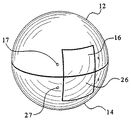
別の実施形態では、第1及び第2可動部材は全体的に正方形状をしており、かつ互いに向き合うように近づいて実質的な閉鎖位置で立方体を構成する。第1及び第2可動部材は何れか適切な寸法又は形状とし得ることを認識すべきである。 In another embodiment, the first and second movable members are generally square-shaped and approach to face each other to form a cube in a substantially closed position. It should be appreciated that the first and second movable members can be any suitable size or shape.
従って、異なる玩具に変形する、変形可能な玩具を提供することは、本発明の利点である。 Accordingly, it is an advantage of the present invention to provide a deformable toy that transforms into a different toy.
異なる機能を有する、異なる玩具に変形する、変形可能な玩具を提供することは本発明の別の利点である。 It is another advantage of the present invention to provide a deformable toy that has different functions and transforms into different toys.
本発明の追加機構及び利点は以下の本発明の詳細な説明に記載され、かつ該詳細な説明から明らかとなる。 Additional features and advantages of the present invention are described in, and will be apparent from, the following Detailed Description of the Invention.
本発明は、一般的に、玩具に関し、特に、小像を顕示及び隠すために開閉するように構成された変形可能な玩具に関する。 The present invention relates generally to toys, and more particularly to a deformable toy configured to open and close to reveal and conceal a statuette.
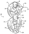
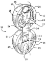
ここで、図1〜4を参照すると、一実施形態では、変形可能な玩具10は第1可動部材12、第2可動部材14、および、第1可動部材と第2可動部材の間に連結された連結器であるヒンジ20を含む。一実施形態では、第1可動部材及び第2可動部材は対応する半円形形状を有する。第1可動部材は、連結器20一端部に可動に連結され、かつ連結器の端部を貫通して延在する水平軸線の周りに動いて回動すなわち回転する。同様に、第2可動部材14は、連結器20の反対側端部に可動に連結され、かつ連結器の端部を貫通して延在する水平軸線の周りに動いて回動すなわち回転する。第1可動部材12及び第2可動部材14は、これら第1可動部材及び第2可動部材が互いに実質的に隣接するか、あるいは図4に図示するように閉位置にくるまで互いに対向するように移動することができる。第1可動部材12及び第2可動部材14は、図1に図示するような開位置にくるまで互いに離れて移動することができる。この実施形態では、第1可動部材12及び第2可動部材14は、半円筒形状を有し、かつ同じ寸法をしている。第1及び第2可動部材は同じ形状、異なる形状、あるいは任意の適切な形状を有し得ることを認識すべきである。第1及び第2可動部材が同じ寸法、異なる寸法、あるいは任意の適切な寸法とし得ることも認識すべきである。別の実施形態では、連結器であるヒンジは、第1可動部材及び第2可動部材の端部に一体形成され、かつ第1及び第2可動部材が、上述したように、互いに対向するように及び互いに遠ざかるように回動すなわち移動することを可能にする。また別の実施形態では、第1及び第2可動部材はこれら第1及び第2可動部材が互いに対向するように及び互いに遠ざかるように回動すなわち移動することを可能にするためにヒンジ式に結合される
1-4, in one embodiment, the
一実施形態では、表示部材13は、それぞれ、第1及び第2可動部材12及び14の少なくとも1つの内側表面に結合される。この実施形態では、表示部材13は図又は小像である。表示部材が、図、物体、文字、画像、動物、形状又は何れか他の適切な形状構成、あるいは物体とし得ることを認識すべきである。この実施形態では、表示部材13は図又は小像であり、かつ図の頭部として形成された第1リビーラー16と、第1リビーラー16に隣接して位置する本体18と、本体18の互いに反対側に可動に連結された腕形態の一対の第2リビーラー24と、第1及び第2可動部材の間に連結された連結器20と、連結器に隣接して位置する支持部22と、支持部22に隣接して位置し、かつ第2可動部材に可動に連結された第3リビーラー26と、を含む。別の実施形態では、連結器20は、第1及び第2可動部材の外面に取り付けられる。したがって、この実施形態では、表示部材13は、第1及び第2可動部材の内側表面に連結された図又は物体の一部としての連結器を含まない。
In one embodiment, the
一実施形態では、第1可動部材12は、図1に図示するような中空内部部分を具備する半円筒形状をしている。本体部材である本体18は、第1可動部材12の内側表面に結合される。一実施形態では、本体18は、適切な接着剤又は他の適切な接着方法を使用して、第1可動部材の内側表面に固定結合された個別部品である。別の実施形態では、本体18は、第1可動部材の内側表面に一体成形される。
In one embodiment, the first
一実施形態では、第1顕示部材である第1リビーラー16は本体18の頂部に隣接して位置し、かつ第1可動部材12に可動に連結される。第1リビーラーは、第1リビーラー16の各側から延在する回動部材である回動ピン17を含む。回動ピン17の各端部は、第1可動部材12に可動に連結される。一実施形態では、回動ピンは第1リビーラーに取り付けられた別個の構成要素である。別の実施形態では、回動ピン17は、第1リビーラーと一体成形される。回動ピン17は、第1リビーラーが、第1可動部材12の一端部を全体的に貫通して延在する水平軸線の周りで移動、回動又は回転することを可能にするように構成される。特に、第1リビーラー16は図3に示す、隠された位置から図1に示す、顕示位置まで移動可能すなわち回転可能である。第1リビーラー16は隠された位置から顕示位置まで及び顕示位置から隠された位置まで移動し得ることを理解すべきである。
In one embodiment, the
一実施形態では、第1リビーラー、図1に示すような正面(face)すなわち顔のような画像を有する少なくとも1つの表面を含む。第1リビーラーが、図3に示すような隠された位置にある時、画像は隠されるか又は覆い隠される。第1リビーラーが図1に示すような顕示位置まで移動する時、顔は、この時、顕示され、露出されるか、あるいは視認し得る。変形可能な玩具の各々が同一の画像又は顔。少なくとも1つの異なる画像又は顔、あるいは複数の異なる画像又は顔を含み得ることを理解すべきである。第1リビーラー16の1つ以上の表面がこうした顔の画像を含み得ることも理解すべきである。
In one embodiment, the first reboiler includes at least one surface having a face or face-like image as shown in FIG. When the first rebeiler is in a hidden position as shown in FIG. 3, the image is hidden or obscured. When the first reboiler moves to the revealing position as shown in FIG. 1, the face is now revealed and exposed or visible. Each deformable toy has the same image or face. It should be understood that it may include at least one different image or face, or multiple different images or faces. It should also be understood that one or more surfaces of the
一実施形態では、少なくとも1つの第2顕示部材である第2リビーラー、および好ましくは2つの第2リビーラー24が本体18に可動に連結される。図示した実施形態では、第2リビーラー24は小像の腕として構成される。第2リビーラー24は何れかの適切な寸法又は形状とし得ることを認識すべきである。第2リビーラー24は、本体18の反対側に可動すなわち回転可能に連結される。第2リビーラーは本体の何れか適切な側に連結し得ることを認識すべきである。回動ピンのようなコネクター(図示せず)が第2リビーラー24及び本体18の各々に連結され、第2リビーラーを本体に対して移動すなわち回転可能にしている。第2リビーラー24は、図3に示すような後退位置から、図1に示すような延長されたか又は後退されていない位置まで移動する。第2リビーラーは、後退位置から延長位置まで及び延長位置から後退位置まで移動し得ることを理解すべきである。
In one embodiment, at least one second revealer, a second re-beer, and preferably two
本体18、第1リビーラー16(すなわち、小像の頭部)、及び第2リビーラー24(すなわち、小像の腕)は協働又は共同して第1可動部材12の内側表面に連結された小像の上側部分を構成する。
The
一実施形態では、第2可動部材14は、図1に図示するような中空内部部分を具備する半円筒形状をしている。支持部材である支持部22は、第2可動部材14の内側表面に連結される。一実施形態では、支持部22は、適切な接着剤又は他の適切な取付方法を使用して、第1可動部材の内側表面に固定連結された別個の部材である構成要素である。別の実施形態では、支持部22は、第2可動部材の内側表面と一体成形される。
In one embodiment, the second
一実施形態では、第3顕示部材である第3リビーラ26は支持部22の底部に隣接して位置し、かつ第2可動部材14に可動に連結される。第3リビーラーは、第3リビーラー26の各側から延在する回動部材である回動ピン27を含む。回動ピン27の各端部は第2可動部材14に可動に連結される。一実施形態では、回動ピン27は第3リビーラーに取り付けられる別個の構成要素である。別の実施形態では、回動ピン27は、第3リビーラーと一体成形される。回動ピン27は、第3リビーラーを、第2可動部材14の一端部を全体的に貫通して延在する水平軸線の周りに移動、回動又は回転可能にするように構成される。特に、第3リビーラー26は、図3に示す、隠された位置から、図1に示す顕示され、露出され、あるいは隠されていない位置まで移動可能すなわち回転可能である。第3リビーラー26が隠された位置から顕示位置まで及び顕示位置から隠された位置まで移動し得ることを理解すべきである。
In one embodiment, the
一実施形態では、第3リビーラー26は、図1に示すような画像を具備する少なくとも1つの表面を含む。第3リビーラーが図3に示すような隠れた位置にある場合、該第3リビーラー26(すなわち、小像の脚)は見えないようにされるか隠される。その後、第3リビーラーは支持部22から図1に示すような顕示位置まで遠ざかるように移動、回動、あるいは回転される。
In one embodiment, the
さらに、第3リビーラーは、第1リビーラー16の頂面28の寸法及び形状に相当する受容器である凹表面30を含む。第1可動部材及び第2可動部材が互いに図4に示す閉位置まで移動する時、第1リビーラー16の頂面28は受容器30内にぴったりと入る。頂面28及び受容器30の噛合い係合は、第1及び第2可動部材が互いに閉じることを可能にする。
In addition, the third reboiler includes a
支持部22及び第3リビーラー26(すなわち、小像の脚)は協働又は共同して、第2可動部材14の内側表面に連結された小像の下部又は底部を構成する。
The
従って、第1可動部材12の内側表面に連結された小像の上部と、第2可動部材14の内側表面に連結された小像の下部と、は協働して変形可能な玩具10の小像を構成する。何れかの適切な絵、小像、形状構成、文字、あるいは何れか他の適切な物体が第1及び第2可動部材の内側表面に構成又は連結し得ることを理解すべきである。
Accordingly, the upper portion of the small image connected to the inner surface of the first
一実施形態では、玩具10は錠止部材又は錠(図示せず)を含む。錠は、第1及び第2可動部材の少なくとも1つに連結され、かつ第1及び第2可動部材が閉位置にある時に、該第1及び第2可動部材を解放可能に共に固定するように構成される。何れか適切な錠、ラッチ又は固定部材が第1及び/又は第2可動部材に取り付け得ることを理解すべきである。
In one embodiment, the
図5を参照すると、各々が立方体又は全体的に正方形状を有する第1可動部材102及び第2可動部材104を変形可能な玩具100が含む、本発明の別の実施形態が図示されている。この実施形態では、第1リビーラー106は、第1可動部材102に回転可能に取り付けられ、かつ本体108に隣接している。玩具は、腕として構成された1対の第2リビーラー114を含む。連結器110は、第1及び第2可動部材102及び104の各々の一端部のそれぞれに回転可能に連結されている。一対の脚として形成された支持部112は、第2可動部材104の内側表面に連結される。脚として形成された第3リビーラー116は、第2可動部材104に回転可能に連結される。第1可動部材及び第2可動部材を何れかの適切な形状又は形状構成とし得るものであり、かつ何れか適切な寸法を有し得るものとすることを理解すべきである。
Referring to FIG. 5, another embodiment of the present invention is illustrated in which a
作用
図1〜図4を参照すると、一実施形態では、変形可能な玩具10は、玩具の内側表面に取り付けられた小像のような物体を顕示又は隠すために全体的に開閉する。最初に、玩具の第1可動部材12及び第2可動部材14は連結器20の周りで互いに近づくように図4に示すような閉位置まで移動すなわち回動する。閉位置では、玩具10は、転がり、弾み、動かし、あるいはスピンを付け得る球又はボールを構成する。この様にして、玩具10はビー玉遊び又は何れか他の適切なゲームをするために使用し得る。
With reference to FIGS. 1-4, in one embodiment, the
玩具内部の小像を顕示するために変形可能な玩具10を開くために、使用者は第1及び第2可動部材12及び14をそれぞれ分離するか、引っ張るか、あるいは第1及び第2可動部材を押圧する。使用者は、第1及び第2可動部材が実質的に遠ざかった図1に示す開位置にくるまで、連結器20の周りで第1及び第2可動部材を移動すなわち回動させる。開位置では、第1可動部材12は、第2可動部材14に隣接し且つ該第2可動部材14より上に位置する。この位置では、第1及び第2可動部材の内側表面は図1に図示するのと全体的に同一な方向に面するか又は示す。
To open the
変形可能な玩具10が開位置にある時、使用者は小像の第1リビーラーである頭部16を第1可動部材12の内側表面12から上向きに遠ざけるように移動すなわち回転させる。頭部の一表面に含まれた顔が図1に示すように該頭部から外向きに面するか、あるいは実質的に視認し得るまで、頭部は上向きに移動又は回転する。使用者は、この時、第2リビーラーである腕24の1つ以上を、第1可動部材12の内側表面から図1に示す延長位置まで移動させる。腕24は、本体18に対して上向き又は下向きに何れか適切な単数又は複数の位置まで独立して移動し得る。脚部分の底部表面が第2可動部材14の内側表面に対して横方向すなわち長手方向に直角になるまで、使用者は、この時、第3リビーラーである小像26の脚部分を移動すなわち回転させる。脚部分26の底部表面は、玩具10をテーブルタップのような平坦な表面上で直立することを可能にするために実質的に平らすなわち平坦である。リビーラー部材であるリビーラーの全てが隠された位置から顕示されるか又は移動された後で、玩具10は作動文字又は他の適切な文字のような移動可能な字又は小像として使用し得る。
When the
玩具10を閉位置まで戻すために、使用者は脚26を支持部22に向けて上向きに移動すなわち回動させ、腕を第1可動部材12の内側表面に向けて内向きに移動すなわち回動させ、頭部16を、図3の矢印で全体的に示すような第1可動部材の内側表面に向けて下向きに移動すなわち回動させる。特に、脚26は、図4に示すような第2可動部材14の丸みのある外側表面に相当する丸みのある表面を顕示するために回動する。さらに、受容器30は頭部16の頂面28に係合するように位置づけられる。腕24は内向きに回動して、第1及び第2可動部材を共に閉じることを可能にするように、対応する開放空間である第2可動部材14によって画成される受容領域29内にぴったりと嵌まる。頭部16は顔を隠し、かつ頭部16の丸みのある外側表面を第1可動部材12の丸みのある外側表面と整合させるように移動すなわち回動する。第1及び第2可動部材が図4に示す閉位置まで互いに実質的に隣接するまで、使用者は第1及び第2可動部材を連結器20の周りで互いに近づくように移動すなわち回動させる。
In order to return the
したがって、本発明の変形可能な玩具10は、この玩具10が閉位置まで回動してボールとして使用し得るため、こうした子供の使用者にわくわくするような興奮と楽しみを与える。玩具10は直立し、かつアクションフィギュア又は装飾ディスプレイとして使用し得る画像又は小像を顕示するために開放し得る。小像が何れか適切な小像とし得るものであり、かつ何れか適切な寸法、画像、顔、あるいは形状を有し得ることを理解すべきである。さらに、可動部材、リビーラー、本体、支持部あるいは何れか他の適切な構成要素の形状及び寸法は、任意の適切な寸法、形状又は形状構成とし得る。
Therefore, the
上述した玩具は1つ以上の顕示部材であるリビーラーを含むが、この玩具はリビーラーを含まないか(すなわち、画像又は他の物体が、第1及び第2可動部材の少なくとも1つの内側表面に形成される)、1つのリビーラー又は複数のリビーラーを含み得るものとし得ることを理解すべきである。 The toy described above includes one or more revealing members, a rebeer, but the toy does not include a rebeer (i.e., an image or other object is formed on at least one inner surface of the first and second movable members. It is to be understood that one or more re-beilers may be included.
本願明細書に記述した本発明の好ましい実施形態に対する種々の変形及び変更が当業者には自明であることを理解すべきである。こうした変形及び変更は本発明の精神及び範囲から逸脱せず、かつその意図した利便性を減じることなく成し得る。従って、こうした変形及び変更は添付の特許請求の請求項によって網羅されることを意図している。 It should be understood that various changes and modifications to the presently preferred embodiments described herein will be apparent to those skilled in the art. Such variations and modifications can be made without departing from the spirit and scope of the present invention and without diminishing its intended convenience. Accordingly, such modifications and changes are intended to be covered by the appended claims.
10 玩具
12 第1可動部材
13 表示部材
14 第2可動部材
16 第1リビーラー
17、27 回動ピン
18 本体
20 連結器
22 支持部
24 第2リビーラー
26 第3リビーラー
28 頂面
29 受容領域
30 受容器
100 変形可能な玩具
102 第1可動部材
104 第2可動部材
106 第1リビーラー
108 本体
110 連結器
112 支持部
114 第2リビーラー
116 第3リビーラー
DESCRIPTION OF
Claims (36)
前記第1可動部材に隣接して位置し、前記第1可動部材にヒンジ式に連結された第2可動部材であって、前記第1可動部材及び前記第2可動部材が開位置まで互いに遠ざかるように移動されるか、あるいは閉位置まで互いに近づくように移動される、前記第2可動部材と、
前記第1可動部材及び前記第2可動部材の少なくとも1つの表面に連結された表示部材であって、前記表示部材は、前記前記第1可動部材及び前記第2可動部材が前記開位置にある時に解放される、前記表示部材と、を備える玩具。 A first movable member;
A second movable member located adjacent to the first movable member and hinged to the first movable member, wherein the first movable member and the second movable member are moved away from each other to an open position. The second movable member that is moved to or close to each other to a closed position;
A display member connected to at least one surface of the first movable member and the second movable member, wherein the display member is located when the first movable member and the second movable member are in the open position; A toy comprising the display member to be released.
前記第1可動部材は前記連結器の一端部に可動に連結され、
前記第2可動部材は前記連結器の反対側端部に可動に連結される、請求項1に記載の玩具。 A coupler located between the first movable member and the second movable member;
The first movable member is movably coupled to one end of the coupler;
The toy according to claim 1, wherein the second movable member is movably coupled to an opposite end of the coupler.
前記錠は前記第1可動部材及び前記第2可動部材を解放可能に固定するように構成される、請求項1に記載の玩具。 Including a lock coupled to at least one of the first movable member and the second movable member;
The toy of claim 1, wherein the lock is configured to releasably secure the first movable member and the second movable member.
前記第1可動部材に隣接して位置し、前記第1可動部材にヒンジ式に連結された第2可動部材と、
前記第1可動部材及び前記第2可動部材を開位置まで互いに遠ざかるように移動させるか、あるいは閉位置まで互いに近づくように移動させることを可能にする、前記第1可動部材及び前記第2可動部材の間に位置する移動手段と、
前記第1可動部材及び前記第2可動部材の少なくとも1つの表面に連結された表示部材であって、前記表示部材は、前記前記第1可動部材及び前記第2可動部材が前記開位置にある時に顕示される、前記表示部材と、を備える玩具。 A first movable member;
A second movable member located adjacent to the first movable member and connected to the first movable member in a hinged manner;
The first movable member and the second movable member that allow the first movable member and the second movable member to move away from each other to an open position, or to move closer to each other to a closed position. Moving means located between,
A display member connected to at least one surface of the first movable member and the second movable member, wherein the display member is located when the first movable member and the second movable member are in the open position; A toy comprising the display member revealed.
前記第1可動部材は前記連結器の一端部に可動に連結され、
前記第2可動部材は前記連結器の反対側端部に可動に連結される、請求項10に記載の玩具。 The moving means includes a coupler located between the first movable member and the second movable member,
The first movable member is movably coupled to one end of the coupler;
The toy according to claim 10, wherein the second movable member is movably coupled to an opposite end of the coupler.
前記錠は前記第1可動部材及び前記第2可動部材を共に解放可能に固定するように構成される、請求項10に記載の玩具。 Including a lock coupled to at least one of the first movable member and the second movable member;
The toy of claim 10, wherein the lock is configured to releasably secure both the first movable member and the second movable member.
前記第1可動部材に隣接して位置する第2可動部材と、
前記第1可動部材及び前記第2可動部材の間に位置する連結器であって、前記第1可動部材は前記連結器の一端部に可動に連結され、前記第2可動部材は前記連結器の反対側端部に可動に連結され、前記第1可動部材及び前記第2可動部材を開位置まで互いに遠ざかるように移動させるか、あるいは閉位置まで互いに近づくように移動させる、前記連結器と、
前記第1可動部材及び前記第2可動部材の少なくとも1つに可動に連結され、前記第1可動部材及び前記第2可動部材が前記開位置にある時に、自身の少なくとも1つの表面を顕示するように移動されるリビーラーと、を備える玩具。 A first movable member;
A second movable member located adjacent to the first movable member;
A coupler located between the first movable member and the second movable member, wherein the first movable member is movably coupled to one end of the coupler, and the second movable member is coupled to the coupler; The coupler movably connected to the opposite end, and moving the first movable member and the second movable member away from each other to an open position, or moving closer to each other to a closed position;
At least one of the first movable member and the second movable member is movably connected, and reveals at least one surface of the first movable member and the second movable member when the first movable member and the second movable member are in the open position. A toy comprising a re-beerer moved to
前記錠は前記第1可動部材及び前記第2可動部材を共に解放可能に固定するように構成される、請求項19に記載の玩具。 Including a lock coupled to at least one of the first movable member and the second movable member;
The toy of claim 19, wherein the lock is configured to releasably secure both the first movable member and the second movable member.
前記第1可動部材に隣接して位置する第2可動部材と、
前記第1可動部材及び前記第2可動部材を開位置まで互いに遠ざかるように移動させるか、あるいは閉位置まで互いに近づくように移動させることを可能にする、前記第1可動部材及び前記第2可動部材の間に位置する移動手段と、
少なくとも1つの画像を顕示し、前記第1可動部材及び前記第2可動部材の少なくとも1つに連結され、前記前記第1可動部材及び前記第2可動部材が前記開位置にある時に少なくとも1つの画像を顕示する顕示手段と、を備える玩具。 A first movable member;
A second movable member located adjacent to the first movable member;
The first movable member and the second movable member that allow the first movable member and the second movable member to move away from each other to an open position, or to move closer to each other to a closed position. Moving means located between,
At least one image is revealed and is connected to at least one of the first movable member and the second movable member, and at least one image when the first movable member and the second movable member are in the open position. And a revealing means for revealing the toy.
前記第1可動部材に隣接して位置する第2可動部材と、
前記第1可動部材及び前記第2可動部材の間に位置する連結器であって、前記第1可動部材は前記連結器の一端部に可動に連結され、前記第2可動部材は前記連結器の反対側端部に可動に連結され、前記第1可動部材及び前記第2可動部材を開位置まで互いに遠ざかるように移動させるか、あるいは閉位置まで互いに近づくように移動させる、前記連結器と、
前記第1可動部材に可動に連結された頭部と、
前記頭部に隣接して位置し、かつ前記第1可動部材の内側表面に装着される本体と、
前記本体の反対側に位置し、かつ該本体に可動に連結された少なくとも1つの腕と、
前記第2可動部材の内側表面に連結された支持部と、
前記支持部に隣接して位置し、かつ前記第2可動部材に可動に連結された基体であって、前記頭部、前記腕、及び前記基体は、前記第1可動部材及び前記第2可動部材が前記開位置にある時に後退位置から顕示位置まで独立して可動であり、及び、前記頭部、前記腕、及び前記基体は、前記第1可動部材及び前記第2可動部材が前記閉位置にある時に前記顕示位置から前記後退位置まで独立して可動である、前記基体と、を備える玩具。 A first movable member;
A second movable member located adjacent to the first movable member;
A coupler located between the first movable member and the second movable member, wherein the first movable member is movably coupled to one end of the coupler, and the second movable member is coupled to the coupler; The coupler movably connected to the opposite end, and moving the first movable member and the second movable member away from each other to an open position, or moving closer to each other to a closed position;
A head movably coupled to the first movable member;
A main body located adjacent to the head and attached to the inner surface of the first movable member;
At least one arm located on the opposite side of the body and movably coupled to the body;
A support connected to the inner surface of the second movable member;
A base that is located adjacent to the support and is movably connected to the second movable member, wherein the head, the arm, and the base are the first movable member and the second movable member. Is independently movable from the retracted position to the revealing position when the is in the open position, and the head, the arm, and the base body are in the closed position when the first movable member and the second movable member are in the closed position. A toy comprising the base body, which is movable independently from the revealing position to the retracted position at a certain time.
前記錠は前記第1可動部材及び前記第2可動部材を共に解放可能に固定するように構成される、請求項31に記載の玩具。 Including a lock coupled to at least one of the first movable member and the second movable member;
32. The toy of claim 31, wherein the lock is configured to releasably secure both the first movable member and the second movable member.
32. The toy according to claim 31, wherein the base includes a receptacle formed to engage and engage the head when the first and second movable members are in the closed position.
Applications Claiming Priority (1)
| Application Number | Priority Date | Filing Date | Title |
|---|---|---|---|
| US10/889,488 US7306504B2 (en) | 2004-07-12 | 2004-07-12 | Transformable toy |
Related Child Applications (1)
| Application Number | Title | Priority Date | Filing Date |
|---|---|---|---|
| JP2008046476A Division JP2008132355A (en) | 2004-07-12 | 2008-02-27 | Transformable toy |
Publications (1)
| Publication Number | Publication Date |
|---|---|
| JP2006026384A true JP2006026384A (en) | 2006-02-02 |
Family
ID=35058865
Family Applications (2)
| Application Number | Title | Priority Date | Filing Date |
|---|---|---|---|
| JP2004324259A Pending JP2006026384A (en) | 2004-07-12 | 2004-11-08 | Transformable toy |
| JP2008046476A Pending JP2008132355A (en) | 2004-07-12 | 2008-02-27 | Transformable toy |
Family Applications After (1)
| Application Number | Title | Priority Date | Filing Date |
|---|---|---|---|
| JP2008046476A Pending JP2008132355A (en) | 2004-07-12 | 2008-02-27 | Transformable toy |
Country Status (7)
| Country | Link |
|---|---|
| US (2) | US7306504B2 (en) |
| EP (1) | EP1616609B1 (en) |
| JP (2) | JP2006026384A (en) |
| AT (1) | ATE455584T1 (en) |
| DE (1) | DE602004025222D1 (en) |
| ES (1) | ES2339860T3 (en) |
| HK (1) | HK1084621A1 (en) |
Families Citing this family (34)
| Publication number | Priority date | Publication date | Assignee | Title |
|---|---|---|---|---|
| TWI259986B (en) * | 2004-08-05 | 2006-08-11 | Benq Corp | Electronic device and image configuration thereof |
| TWI261489B (en) * | 2004-12-22 | 2006-09-01 | Micro Star Int Co Ltd | Electronic device with variable configuration functions |
| US20060163220A1 (en) * | 2005-01-27 | 2006-07-27 | Brandt Aaron D | Automatic gas control for a plasma arc torch |
| JP4859206B2 (en) * | 2006-02-20 | 2012-01-25 | 株式会社セガ トイズ | toy |
| WO2009087881A1 (en) * | 2008-01-10 | 2009-07-16 | Sega Toys Co., Ltd. | Toy |
| EP2116289A1 (en) * | 2008-05-09 | 2009-11-11 | Produzioni Editoriali Aprile S.p.A. | Transformable toy |
| US7988524B2 (en) * | 2008-06-02 | 2011-08-02 | Mattel, Inc. | Childrens ride-on vehicles having mechanical assemblies |
| US8182309B2 (en) * | 2008-10-02 | 2012-05-22 | Genie Toys, Plc. | Toy with interchangeable parts |
| US8333634B2 (en) * | 2009-04-01 | 2012-12-18 | Genie Toys Plc | Frames |
| US9526998B2 (en) | 2009-04-06 | 2016-12-27 | Jakks Pacific, Inc. | Spinning toy with trigger actuated stop mechanism |
| CA2773225C (en) * | 2010-07-09 | 2015-10-06 | Jakks Pacific, Inc. | Core with finger indentation and formed to expel an object concealed therein |
| CN101898043B (en) * | 2010-08-19 | 2012-05-30 | 广东奥飞动漫文化股份有限公司 | Deformed disk-shaped toy |
| US9993739B2 (en) | 2010-12-21 | 2018-06-12 | David Weeks Studio LLC | Transformable toy robot |
| CA2741943C (en) * | 2011-06-02 | 2013-08-06 | Spin Master Ltd. | Interconnectable and transformable toy building element |
| US8814629B2 (en) * | 2011-06-21 | 2014-08-26 | Andrew Lewis Johnston | Non-rollable to rollable transforming toy |
| US8974264B2 (en) * | 2012-04-10 | 2015-03-10 | Jakks Pacific, Inc. | Figurine launcher |
| WO2013173937A1 (en) * | 2012-05-24 | 2013-11-28 | Blanco Publicidad Y Marketing Limitada | Toy comprising two bodies and including a pop-out gear |
| US9108116B2 (en) * | 2012-10-03 | 2015-08-18 | Paul Swartz | Container with articulatable statuette |
| US9101847B2 (en) * | 2013-03-15 | 2015-08-11 | Bang Zoom Design, Ltd. | Shape changing apparatus and method |
| CN104213848B (en) * | 2013-06-05 | 2017-03-15 | 中国石油天然气股份有限公司 | Arc-shaped sealing device for opening hole of pipeline or drill rod with pressure and using method |
| GB201406782D0 (en) * | 2014-04-15 | 2014-05-28 | Fuse London Ltd | Article moveable between two positions and a method of combining two or more of the same |
| CN104027981B (en) * | 2014-06-20 | 2016-03-23 | 宁波嘉福塑胶电器有限公司 | A kind of doll ball |
| JP5937160B2 (en) * | 2014-08-29 | 2016-06-22 | 株式会社Area81 | Deformed block toy |
| GB201522884D0 (en) * | 2015-12-24 | 2016-02-10 | Asque Ltd | Article moveable between two positions and a method of combining two or more of the same |
| EP3459831A4 (en) * | 2016-05-19 | 2019-11-27 | Brave Robotics Inc. | Transformable robot |
| US10864452B2 (en) * | 2018-01-22 | 2020-12-15 | Darwin William Fernandez | Toy with two bodies and an ejectable gear and retraction mechanism |
| US11219839B2 (en) | 2017-12-06 | 2022-01-11 | Darwin William Fernandez | Button activated transformable rotating toy |
| US10695687B2 (en) | 2017-10-03 | 2020-06-30 | Darwin William Fernandez | Model Toy croms balls |
| KR102030937B1 (en) * | 2018-09-21 | 2019-10-10 | 주식회사 초이락컨텐츠팩토리 | Transformable toy |
| WO2021063791A1 (en) * | 2019-10-01 | 2021-04-08 | Lego A/S | Transformable modular toy element |
| CN111330292B (en) * | 2020-03-09 | 2022-03-29 | 奥飞娱乐股份有限公司 | Deformation toy and gutta-percha deformation toy |
| US11376515B1 (en) | 2021-06-29 | 2022-07-05 | Spin Master Ltd. | Transformable toy |
| US11712636B1 (en) | 2022-08-12 | 2023-08-01 | Spin Master Ltd. | Transformable toy |
| US12011675B1 (en) * | 2023-03-31 | 2024-06-18 | DiscoNifty Ltd. | Rotationally transformable toy between a first configuration and a second configuration |
Family Cites Families (42)
| Publication number | Priority date | Publication date | Assignee | Title |
|---|---|---|---|---|
| US152250A (en) * | 1874-06-23 | Improvement in toys | ||
| US3520078A (en) * | 1967-08-14 | 1970-07-14 | Klamer R B | Self-storing multicharactered toy |
| JPS6122624Y2 (en) * | 1980-12-04 | 1986-07-07 | ||
| DE3048999A1 (en) | 1980-12-24 | 1982-07-15 | Robert Bosch Gmbh, 7000 Stuttgart | CIRCUIT ARRANGEMENT FOR ENERGY RECOVERY IN CHOPPER-CONTROLLED SERIES |
| JPS57126289U (en) | 1981-01-31 | 1982-08-06 | ||
| GB2112407B (en) | 1981-12-14 | 1985-06-19 | Gen Electric | Method of hydrolyzing chlorosilanes |
| JPS58126893U (en) * | 1982-02-23 | 1983-08-29 | 株式会社タイト− | Electronic game board with clock |
| JPS58165881A (en) | 1982-03-29 | 1983-09-30 | 株式会社 バンダイ | Wrist watch for toy |
| AU551388B2 (en) * | 1982-03-29 | 1986-04-24 | Bandai K.K. | Wrist watch type container for toy |
| GB2128489B (en) * | 1982-10-12 | 1986-08-20 | Takara Co Ltd | Reconfigurable toy assembly |
| JPS5991984A (en) * | 1982-11-18 | 1984-05-26 | 山本 一郎 | Sounding ornamental bag |
| GB2137105A (en) * | 1983-03-30 | 1984-10-03 | Wiggs C C | Jack-in-the-box type toy |
| JPS60128693A (en) | 1983-12-15 | 1985-07-09 | オムロン株式会社 | Terminal of electronic device |
| JPS60128693U (en) | 1984-02-03 | 1985-08-29 | 株式会社 タカラ | shape changing toys |
| JPS61115593A (en) | 1984-11-12 | 1986-06-03 | ジューキ株式会社 | Sewing machine |
| US4581904A (en) * | 1984-12-20 | 1986-04-15 | Lehmann Roger W | Toy jewelry item with parts movable to a hidden position |
| JPH0234933Y2 (en) | 1984-12-28 | 1990-09-20 | ||
| JPS61159980A (en) * | 1984-12-29 | 1986-07-19 | 株式会社 増田屋コ−ポレ−シヨン | Block toy deformable to robot |
| US4687459A (en) * | 1985-11-06 | 1987-08-18 | Lockett G Jeffrey | Baby toy |
| US4696656A (en) * | 1986-01-14 | 1987-09-29 | Mattel, Inc. | Reconfigurable toy |
| US4708687A (en) * | 1986-02-07 | 1987-11-24 | Coleco Industries, Inc. | Rolling figure toy |
| US4817936A (en) * | 1986-04-30 | 1989-04-04 | Takara Co., Ltd. | Spring-powered toy |
| IT1219205B (en) * | 1988-04-13 | 1990-05-03 | Ferrero Spa | COMPLEX OF GIFT ITEM AND RELATED WRAPPING PARTICULARLY FOR CHOCOLATE EGGS AND SIMILAR FOOD PRODUCTS CABLES AND PACKAGING PROCEDURE |
| US5019010A (en) * | 1988-04-15 | 1991-05-28 | Tomy Company, Ltd. | Transformable block toys |
| US4874340A (en) * | 1988-07-21 | 1989-10-17 | Smallwood Alice R | Combined amusement device and transport and storage pack |
| US5209345A (en) * | 1990-04-24 | 1993-05-11 | Connie Haugabook | Combination storage and display unit |
| US5090935A (en) | 1990-12-17 | 1992-02-25 | Monson Chris S | Composite toy having interconnectable toy components |
| US5090938A (en) * | 1991-03-27 | 1992-02-25 | Christopher Reynolds | Toy or other object alterable between two different shapes |
| US5310378A (en) * | 1992-06-01 | 1994-05-10 | Shannon Suel G | Transformable toy |
| JP3001886U (en) * | 1994-03-10 | 1994-09-06 | パイオニア精密株式会社 | binoculars |
| US5855499A (en) * | 1995-06-27 | 1999-01-05 | Kabushiki Kaisha Bandai | Packaging apparatus mounting a displayed article using a component of the article |
| US6203393B1 (en) * | 1996-05-29 | 2001-03-20 | The All-Round Company Limited | Toy |
| US6126507A (en) * | 1997-03-13 | 2000-10-03 | Chameleon Products, Inc. | Reversible doll/hat |
| US6261146B1 (en) * | 1998-05-08 | 2001-07-17 | Donald Spector | Package containing a shrunken body |
| US6089950A (en) * | 1998-06-01 | 2000-07-18 | C. J. Associates, Ltd. | Toy figure with articulating joints |
| US6231346B1 (en) * | 1999-12-06 | 2001-05-15 | Snubelgrass Interactive Ltd. | Interactive hatching egg |
| US6261149B1 (en) * | 2000-04-20 | 2001-07-17 | Shane A. Moore | Reversible doll toy |
| GB2367766A (en) * | 2000-10-16 | 2002-04-17 | Genie Toys Plc | Compressible toy figure and container. |
| US6719606B1 (en) * | 2001-07-11 | 2004-04-13 | Judy Mukensturm | Soft sculpture shellfish animal toy and accessories |
| JP3935364B2 (en) * | 2002-02-04 | 2007-06-20 | 株式会社バンダイナムコゲームス | Object supply device |
| US6572436B1 (en) * | 2002-02-07 | 2003-06-03 | May Cheong Toy Products Factory Limited | Toy station |
| US6752679B1 (en) * | 2003-11-19 | 2004-06-22 | Hoe King Lui | Double doll figurine |
-
2004
- 2004-07-12 US US10/889,488 patent/US7306504B2/en active Active
- 2004-10-27 EP EP04256605A patent/EP1616609B1/en active Active
- 2004-10-27 AT AT04256605T patent/ATE455584T1/en not_active IP Right Cessation
- 2004-10-27 DE DE602004025222T patent/DE602004025222D1/en active Active
- 2004-10-27 ES ES04256605T patent/ES2339860T3/en active Active
- 2004-11-08 JP JP2004324259A patent/JP2006026384A/en active Pending
-
2006
- 2006-06-14 HK HK06106815.4A patent/HK1084621A1/en unknown
-
2007
- 2007-11-21 US US11/944,126 patent/US7731563B2/en active Active
-
2008
- 2008-02-27 JP JP2008046476A patent/JP2008132355A/en active Pending
Also Published As
| Publication number | Publication date |
|---|---|
| EP1616609B1 (en) | 2010-01-20 |
| JP2008132355A (en) | 2008-06-12 |
| US20080070471A1 (en) | 2008-03-20 |
| US7731563B2 (en) | 2010-06-08 |
| US20060009115A1 (en) | 2006-01-12 |
| DE602004025222D1 (en) | 2010-03-11 |
| ATE455584T1 (en) | 2010-02-15 |
| EP1616609A1 (en) | 2006-01-18 |
| US7306504B2 (en) | 2007-12-11 |
| ES2339860T3 (en) | 2010-05-26 |
| HK1084621A1 (en) | 2006-08-04 |
Similar Documents
| Publication | Publication Date | Title |
|---|---|---|
| JP2006026384A (en) | Transformable toy | |
| JP2013526336A (en) | Variable tough structural toy | |
| TW201136642A (en) | Dice toy | |
| CN207941194U (en) | Can repeatedly somersault toy and can secondary somersault toy car | |
| US20210379501A1 (en) | Creative Construction Set Additional Accessories | |
| JPS61159980A (en) | Block toy deformable to robot | |
| JP6971175B2 (en) | Doll toys | |
| CN104870065B (en) | Container be hinged statue | |
| US20070298676A1 (en) | Construction with Telescoping Jointed Arms | |
| US6666454B1 (en) | Animated clamshell puzzles | |
| US20180229133A1 (en) | Reconfigurable Doll | |
| US6540580B1 (en) | Yo yo having removable toy figures and container playset | |
| AU2003225679B2 (en) | Convertible toy chair and vanity combination | |
| US6120295A (en) | Visual puzzle toy | |
| US6419542B1 (en) | Three-dimensional toy built up with freely connectable parts | |
| US4205851A (en) | Game board | |
| CN202020911U (en) | Combined toy robot | |
| EP1919589B1 (en) | Toy apparatus | |
| CN211935557U (en) | Candy toy | |
| JP2598287Y2 (en) | Playing toy | |
| JP3230666U (en) | toy | |
| CN101505842A (en) | Beauty preparation toys | |
| JPH02159292A (en) | Deformable card-shaped toy | |
| JPH0310799Y2 (en) | ||
| JP2009153663A (en) | Disassembling/assembly type 3-dimensionally changing intellectual training structure |
Legal Events
| Date | Code | Title | Description |
|---|---|---|---|
| A131 | Notification of reasons for refusal |
Free format text: JAPANESE INTERMEDIATE CODE: A131 Effective date: 20060815 |
|
| A601 | Written request for extension of time |
Free format text: JAPANESE INTERMEDIATE CODE: A601 Effective date: 20061115 |
|
| A602 | Written permission of extension of time |
Free format text: JAPANESE INTERMEDIATE CODE: A602 Effective date: 20061120 |
|
| A521 | Request for written amendment filed |
Free format text: JAPANESE INTERMEDIATE CODE: A523 Effective date: 20070215 |
|
| A131 | Notification of reasons for refusal |
Free format text: JAPANESE INTERMEDIATE CODE: A131 Effective date: 20070410 |
|
| A601 | Written request for extension of time |
Free format text: JAPANESE INTERMEDIATE CODE: A601 Effective date: 20070710 |
|
| A602 | Written permission of extension of time |
Free format text: JAPANESE INTERMEDIATE CODE: A602 Effective date: 20070713 |
|
| A521 | Request for written amendment filed |
Free format text: JAPANESE INTERMEDIATE CODE: A523 Effective date: 20071010 |
|
| A02 | Decision of refusal |
Free format text: JAPANESE INTERMEDIATE CODE: A02 Effective date: 20071106 |
|
| A521 | Request for written amendment filed |
Free format text: JAPANESE INTERMEDIATE CODE: A523 Effective date: 20080204 |