JP7149564B2 - game machine - Google Patents
game machine Download PDFInfo
- Publication number
- JP7149564B2 JP7149564B2 JP2018112444A JP2018112444A JP7149564B2 JP 7149564 B2 JP7149564 B2 JP 7149564B2 JP 2018112444 A JP2018112444 A JP 2018112444A JP 2018112444 A JP2018112444 A JP 2018112444A JP 7149564 B2 JP7149564 B2 JP 7149564B2
- Authority
- JP
- Japan
- Prior art keywords
- game
- special
- state
- jackpot
- display
- Prior art date
- Legal status (The legal status is an assumption and is not a legal conclusion. Google has not performed a legal analysis and makes no representation as to the accuracy of the status listed.)
- Active
Links
Images


Landscapes
- Pinball Game Machines (AREA)
Description
本発明は、遊技機に関し、特にパチンコ遊技機等に適用することができる。 The present invention relates to gaming machines, and is particularly applicable to pachinko gaming machines and the like.
遊技機には、貸球や賞球としての遊技球を払い出す払出装置(払出手段)が設けられている。当該払出装置は、一般に、払出用のモータやソレノイド等の駆動により遊技球を払い出すことが可能に構成されている(例えば特許文献1を参照)。
A game machine is provided with a payout device (payout means) for paying out game balls as rental balls or prize balls. The payout device is generally configured to be able to pay out game balls by driving a payout motor, solenoid, or the like (see
前述の払出装置を備えた遊技機では、例えば、大当り等の発生により遊技者にとって有利な特別遊技が開始されると、当該特別遊技中、大入賞口等の所定の入球口への遊技球の入球に基づいて多量の賞球が払い出される。この場合、払出装置は連続的に払出動作を行うこととなるが、連続的な払出動作は払出装置に負荷がかかり、払出モータ等の発熱により払出装置が故障する虞がある。この点、特許文献1に記載の技術では、遊技球1個の払い出しにつき払出モータの駆動を一時的に停止させて払出モータの発熱(温度上昇)を抑えるものとしているが、このように1個払い出すごとに払出モータの駆動停止と駆動開始を繰り返すのでは、払出モータの駆動制御が煩雑となってしまう。
In a gaming machine equipped with the above-described payout device, for example, when a special game advantageous to the player is started due to the occurrence of a big win or the like, a game ball is inserted into a predetermined ball entrance such as a big winning opening during the special game. A large amount of prize balls are paid out based on the number of incoming balls. In this case, the dispensing device continuously performs the dispensing operation, but the continuous dispensing operation places a load on the dispensing device, and there is a possibility that the dispensing device may malfunction due to heat generated by the dispensing motor or the like. In this regard, in the technique described in
本発明は、上記事情に鑑みてなされたものであり、その目的とするところは、払出モータ等の電気的駆動源の駆動制御が煩雑になるのを回避しつつ、電気的駆動源の温度上昇を抑えることが可能な遊技機を提供することにある。 The present invention has been made in view of the above circumstances, and an object of the present invention is to prevent an increase in the temperature of the electric drive source while avoiding complicated drive control of the electric drive source such as a dispensing motor. To provide a game machine capable of suppressing
前述の課題を解決するために、本発明は以下の構成を採用した。
すなわち、本発明の遊技機は、
払出モータの駆動により遊技球を払い出す払出手段を備えた遊技機であって、
前記払出モータに駆動電流を供給する供給手段と、
前記払出モータを制御する制御手段と、
遊技球の払い出しに関連するエラーを監視するエラー監視手段と、を備え、
前記制御手段は、所定数の遊技球の払出要求を受けて前記払出手段により前記所定数の遊技球を払い出す払出動作の開始条件の成立に基づいて、前記払出モータを通電状態として前記払出モータの駆動を開始する駆動開始制御を実行可能であり、
前記駆動開始制御では、前記払出動作の開始にあたり、前記払出モータの通電開始から所定の無回転通電期間が経過するまでの間、前記払出モータを通電状態としたまま該払出モータの回転軸を回転させない状態とし、前記無回転通電期間の経過に基づいて前記回転軸の回転を開始させ、
さらに前記制御手段は、前記駆動開始制御の実行後、前記所定数の遊技球の払い出しが完了する前に前記エラーが発生した場合、前記払出モータの駆動を停止させる駆動停止制御を実行可能であり、
前記駆動停止制御では、前記無回転通電期間よりも長い期間、前記払出モータを通電状態としたまま前記回転軸の回転を停止させる
ことを要旨とする。
In order to solve the aforementioned problems, the present invention employs the following configurations.
That is, the gaming machine of the present invention is
A gaming machine comprising payout means for putting out game balls by driving a payout motor,
supply means for supplying drive current to the dispensing motor;
a control means for controlling the dispensing motor;
an error monitoring means for monitoring errors related to the payout of game balls ;
The control means receives a payout request for a predetermined number of game balls and turns the payout motor into an energized state on the basis of establishment of conditions for starting a payout operation for paying out the predetermined number of game balls by the payout means. It is possible to execute drive start control to start driving of
In the drive start control, at the start of the payout operation, the rotating shaft of the payout motor is rotated while the payout motor is kept in an energized state until a predetermined non-rotational energization period elapses from the start of the energization of the payout motor. and starting rotation of the rotating shaft based on the lapse of the non-rotating energization period ,
Further, the control means can execute drive stop control for stopping the drive of the payout motor when the error occurs after the drive start control is executed but before the payout of the predetermined number of game balls is completed. ,
In the drive stop control, the rotation of the rotating shaft is stopped while the payout motor is kept in an energized state for a period longer than the non-rotation energizing period.
This is the gist of it.
以上の本発明によれば、払出モータ等の電気的駆動源の駆動制御が煩雑になるのを回避しつつ、電気的駆動源の温度上昇を抑えることが可能となる。 According to the present invention described above, it is possible to suppress the temperature rise of the electric drive source while avoiding the drive control of the electric drive source such as the payout motor from becoming complicated.
次に、本発明の実施の形態を、実施例を用いて説明する。以下の実施例では、遊技に用いる遊技媒体が遊技球とされ、当該遊技球を遊技盤面に向けて発射することで遊技を進行させることが可能なパチンコ遊技機(弾球遊技機)に、本発明を適用したものについて説明する。具体的には、始動口への遊技球の入球に基づいて特別図柄の変動表示を行い、当該特別図柄の変動表示の終了に伴い大当り図柄が停止表示されると、遊技者に所定量の遊技利益(例えば、賞球)が付与され得る大当り遊技(特別遊技)が実行可能となる所謂「1種タイプ」のパチンコ遊技機を例に説明する。
Next, embodiments of the present invention will be described using examples. In the following embodiments, the game medium used in the game is a game ball, and a pachinko game machine (pinball game machine) capable of proceeding with the game by shooting the game ball toward the game board surface. An application of the invention will be described. Specifically, when the special symbols are variably displayed based on the entry of the game ball into the starting port, and when the special symbols variably displayed are stopped and the jackpot symbols are stopped and displayed, the player receives a predetermined amount. A so-called “
尚、以下の説明において、単に前側(前方)とは、遊技機を正面視した場合の手前側(遊技時に遊技者が位置する側)のことであり、単に後側(後方)とは、遊技機を正面視した場合の背面側(裏側)のことである。また、単に上側(上方)、下側(下方)、左側(左方)、右側(右方)とは、遊技機を正面視した場合の上・下・左・右の各方向のことであり、例えば、図1や図3における上側、下側、左側、右側を指す。 In the following description, simply the front side (front) means the front side (the side where the player is positioned during a game) when the gaming machine is viewed from the front, and simply the rear side (rear) means the game machine. It is the rear side (rear side) when the machine is viewed from the front. In addition, simply the upper side (above), the lower side (downward), the left side (left side), and the right side (right side) refer to the respective directions of up, down, left, and right when the game machine is viewed from the front. , for example, refer to upper, lower, left, and right sides in FIGS.
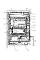
図1~図3に示すように、本実施例のパチンコ遊技機1は、遊技機枠50と、遊技機枠50内に取り付けられた遊技盤2とを備えており、遊技盤2は遊技機枠50から着脱自在に構成されている。図3は、遊技盤2を遊技機枠50から取り外した状態のものを示す。遊技機枠50は、装飾面を有する前面枠51と、遊技盤2等を取り付ける本体枠52と、パチンコ遊技機1をホールの島設備に取り付けるための外枠53と、を有して構成されており、前面枠51、本体枠52及び外枠53は、一側端側で軸支され夫々開閉可能に構成されている。
As shown in FIGS. 1 to 3, the
図1に示すように、前面枠51には、遊技者の操作量(回転角度)に応じた発射強度で遊技球を発射させるための発射ハンドル60、遊技に使用する遊技球を貯留し貯留した遊技球を発射装置側に供給可能な打球供給皿(以下「上皿」ともいう)61及び上皿61に収容しきれない遊技球を貯留する余剰球受皿(以下「下皿」ともいう)62が設けられている。一方、図2に示すように、パチンコ遊技機1の裏面側(本体枠52の裏面)には、ホールの島設備(図示せず)から供給される遊技球を貯留可能な球タンク150と、球タンク150からの遊技球が流下可能な球通路が形成された樋部材151と、樋部材151の球通路を流下してくる遊技球を賞球や貸球として払出可能な払出装置120(払出手段)と、が設けられている。払出装置120により払い出される遊技球は、図示しない遊技球通路を介して上皿61に排出され、上皿61が満杯になると、下皿62に排出される。
As shown in FIG. 1, the
前面枠51における上皿61の上方には、当該前面枠51を閉めた状態で遊技盤2の表面(遊技盤面)を外部から視認可能とする視認窓51aが設けられている。この視認窓51aは透明のガラス板によって構成されており、遊技者は、この視認窓51a(ガラス板)を通して、遊技盤2の表面に形成される後述の遊技領域3や、遊技盤2の裏側に配置される画像表示装置71,72の表示内容等を見ることができる。
Above the
また、前面枠51には、遊技の進行に伴って実行される遊技演出の実行中などに遊技者が操作可能な第1演出ボタン63a、第2演出ボタン63b(これら2個の演出ボタンを総称して単に「演出ボタン63」ともいう)や、遊技の状況に応じて様々な光を発することが可能な装飾用の枠ランプ66、遊技の状況に応じて様々な音(効果音)を発することが可能な左右一対のスピーカ67等も設けられている。枠ランプ66およびスピーカ67は、後述の電源基板109から供給される電力を受けて駆動される演出用の電気部品の一種である。さらに、前面枠51であって上皿61の上面には、CRユニットに受け付けられた記録媒体(例えばカードやコイン)に記録された価値残高(有価残高)の範囲内での遊技球の貸出や記録媒体の返却等のために操作されるCR操作部(図示せず)が設けられている。CR操作部には、遊技球の貸出(つまり、貸球の払い出し)を指示するための球貸ボタン、記録媒体の返却を指示するための返却ボタン、記録媒体に記録されている価値残高(有価残高)を表示する残高表示部(度数表示LED)が設けられている。尚、本実施例のCRユニットは、使用可能な記録媒体がプリペイドカードとされるカードユニット135として構成されている。
In addition, on the
枠ランプ66は、フルカラーLEDにより構成されるもので、当該LEDを実装したLED基板(電飾基板)が前面枠51に設けられている。具体的に、図1に示すように、前面枠51の左辺(視認窓51aの左側)内部には、その上下にわたる長さの左枠LED基板66Lが設けられており、前面枠51の右辺(視認窓51aの右側)内部には、その上下にわたる長さの右枠LED基板66Rが設けられている。そして、これらのLED基板に実装されたLEDと対向する前面枠51の左右手前側は、LEDが発する光を透過可能な(透光性を有する)樹脂性のレンズカバー部とされており、このレンズカバー部により枠ランプ66(枠LED)からの光が拡散されるものとなっている。
The
ここで、本実施例では、前面枠51の左右のレンズカバー部について、それぞれ4つの領域に区分けし、各領域単位で枠ランプ66(枠LED)の発光(左枠LED基板66Lおよび右枠LED基板66Rの駆動)を制御することが可能となっている。すなわち、図1に示すように、前面枠51の左辺のレンズカバー部を、上から順に、左第1領域L1、左第2領域L2、左第3領域L3および左第4領域L4とし、前面枠51の右辺のレンズカバー部を、上から順に、右第1領域R1、右第2領域R2、右第3領域R3および右第4領域R4としている。これらの領域単位で、枠ランプ66(枠LED)の発光態様(点灯、点滅、消灯、色、光量(明るさ)など)を制御することが可能となっており、これにより、各領域の発光態様を異ならせたり、各領域の発光態様を同じとしたりすること等が可能となっている。尚、枠ランプ66(枠LED)を駆動(発光)させる演出のことを「枠発光演出」ともいう。
Here, in this embodiment, the left and right lens cover portions of the
演出ボタン63は、遊技者による入力が可能な入力手段として機能するもので、後述の電源基板109から供給される電力を受けて駆動される演出用の電気部品の一種である。演出ボタン63として、上皿中央の天面に設けられる第1演出ボタン63aと、前面枠51の左下部に手前側に向けて設けられる第2演出ボタン63bとを備えており、遊技演出の種類に応じて使用する演出ボタンを使い分けることができる。例えば、遊技演出の実行中に第1演出ボタン63aまたは第2演出ボタン63bを操作すると、当該操作に基づいて所定の操作対応演出が行われる。尚、演出ボタン63の構成は本実施例の態様に限らず、遊技者が入力を行うことができるものであれば足り、例えば、遊技者が直接ボタン部に接触して入力を行う入力手段(例えば、出没式、タッチセンサ式等)であってもよいし、遊技者の身体の一部が近接したことを検知して入力を行う非接触式の入力手段(光電式等)であってもよい。また、演出ボタンが、後述の電源基板109から供給される電力を受けて、上方や手前側に突出したり振動したりする等の演出動作を行うもの(可動式の演出操作手段)であってもよい。
The performance button 63 functions as an input means for inputting by the player, and is a kind of electrical component for performance that is driven by receiving power supplied from a
さらに、前面枠51の上部であって左右のスピーカ67の間には、後述の電源基板109から供給される電力を受けて駆動される演出用の電気部品の一種である枠可動装飾部材13(枠側可動演出装置)が設けられている。本実施例の枠可動装飾部材13は、主として、上面が開放した箱型の収容部13aと、該収容部13aに収容される演出可動体13b(図49(b)を参照)と、図示しないステッピングモータ等の電気的駆動源とから構成される。枠可動装飾部材13が駆動される前の初期状態では、図1及び図49(a)に示すように、演出可動体13bが収容部13aに収容されて外部に露出(出現)することなく、視認不能な状態となっている(非動作状態、初期状態)。演出可動体13bが収容部13aに収容されている状態(初期状態)において、枠可動装飾部材13による演出の開始条件の成立に基づいて枠可動装飾部材13が駆動(動作)すると、図49(b)に示すように、演出可動体13bが初期位置(収容位置)から所定の動作位置まで上昇して、収容部13a内から上方に突出した状態となり、外部から視認可能となる(動作状態)。また、演出可動体13bには星形を模したエンブレム役物13sが設けられており、当該エンブレム役物13sが、演出可動体13bが突出(出現)した状態で発光、回転等の演出動作を行い得るものとなっている。このように枠可動装飾部材13の駆動により演出可動体13bが出現することで、遊技者は当りへの期待感を高めることとなる。
Furthermore, between the left and
一方、演出可動体13bが動作位置まで移動(上昇)した状態(動作状態)において、枠可動装飾部材13による演出の終了条件の成立に基づいて枠可動装飾部材13が駆動(動作)すると、演出可動体13bが初期位置(原点)まで移動(下降)して、図49(a)に示すように収容部13aに収容された状態となる。尚、演出可動体13bの出没動作(上下動)等を実現する枠可動装飾部材13の機械的構造(構成)については、本発明の要旨に直接関係しないため詳しい説明を省略するが、例えば、ラックアンドピニオンやリードスクリュー、ダンパー等の公知の機構や部材等を用いて構成することが可能である。また、本実施例では、枠可動装飾部材13の駆動により、演出可動体13bが初期位置から動作位置まで移動(到達)するのに要する時間(出現動作時間)と、演出可動体13bが動作位置から初期位置まで移動(到達)するのに要する時間(復帰動作時間)を、それぞれ5500ms(5.5秒)としている。このように、枠可動装飾部材13(演出可動体13b)が比較的ゆっくりとした動作(出現動作、復帰動作)を行うのは、枠可動装飾部材13(演出可動体13b)による演出効果や、駆動した際の振動等の影響を考慮したことによるものである。
On the other hand, in a state (operating state) in which the effect
ここで、図49(a)に示すように、枠可動装飾部材13の駆動前(動作前)であって演出可動体13bが収容部13aに収容された状態(初期状態)のこと「第1状態」ともいい、図49(b)に示すように、枠可動装飾部材13の駆動後であって演出可動体13bが収容部13から上方に突出(出現)した状態(動作状態)のことを「第2状態」ともいう。さらに、枠可動装飾部材13(演出可動体13b)を駆動(動作)させる演出のことを「枠可動演出」ともいう。また、枠可動装飾部材13を駆動させる際の駆動態様として、動作状態(第2状態)にある演出可動体13bを動作位置から初期位置まで下降(移動)させる駆動態様のことを「第1駆動態様」ともいい、初期状態(第1状態)にある演出可動体13bを初期位置(収容位置)から動作位置まで上昇(移動)させる駆動態様のことを「第2駆動態様」ともいう。
Here, as shown in FIG. 49(a), the state (initial state) in which the effect
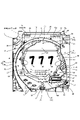
遊技盤2は、アクリルやポリカーボネート等の透明の合成樹脂からなる透明板を主として構成されている。本実施例では、樹脂製の矩形のベース部材に透明板を組み付けたものとしている。図3に示すように、遊技盤2(透明板)の表面(盤面)には、発射ハンドル60の操作により発射された遊技球を案内する略円弧状の案内片4が設けられている。この案内片4は、遊技盤2の表面に突出して設けられるリブ状の突出片や金属製のレール部材等からなるもので、主として、外周側に設けられる外案内片4a(外レール)と、外案内片4aより内側に遊技球の通過を許容する間隔を空けて設けられる内案内片4b(内レール)とにより構成される。尚、遊技盤2のことを「透明遊技盤」ともいう。
The
遊技盤2の盤面のうち、案内片4(外案内片4a)より内側の領域は、遊技球が流下可能な遊技領域3となっている。遊技領域3には、遊技球の動きに変化を与えつつ遊技球を所定方向に誘導する遊技釘(図示せず)や、当該領域内を移動(流下)する遊技球が通過したり入球したりすることが可能なゲート、入球口等が設けられる。尚、ゲートおよび入球口等については後述する。そして、遊技領域3のうち、盤面略中央より左側の領域を左遊技領域3Lとしており、盤面略中央より右側の領域を右遊技領域3Rとしている。また、左遊技領域3L側に位置する内案内片4bの先端(上端)には球戻り防止片6が設けられており、発射ハンドル60の操作により発射された遊技球が球戻り防止片6を越えることで、遊技球は遊技領域3(左遊技領域3L)に進入することが可能となる。尚、球戻り防止片6は、一旦遊技領域3へ誘導された(遊技領域3に進入した)遊技球が発射装置側へ戻るのを防止するものである。
Of the board surface of the
遊技盤2の盤面略中央には開口部2Hが設けられており、当該開口部2Hの開口縁にはセンター装飾体10が装着されている。センター装飾体10(開口部2H)は、遊技盤2の裏側に設けられた下画像表示装置71の表示画面71a(表示領域)の大半と、同じく遊技盤2の裏側に設けられた上画像表示装置72の表示画面72a(表示領域)の一部(画面中央から下方)を、略円弧状に囲む形状となっている。このセンター装飾体10の内側(つまり、開口2H)を通して、下画像表示装置71(表示画面71a)および上画像表示装置72(表示画面72a)の表示内容が視認可能となる。尚、前述したように、遊技盤2は透明遊技盤として構成されていることから、特に、上画像表示装置72(表示画面72a)の表示内容は、センター装飾体10の内側(開口部2Hの上側部分)だけでなく、その周囲の遊技領域3を通して視認すること(透視)が可能となる。
An
また、遊技盤2(遊技領域3)の裏側には、遊技の状況に応じて様々な光を発することが可能な複数の装飾用の盤面ランプ5(図5を参照)が設けられており、盤面ランプ5による装飾(発光)を、遊技領域3(透明遊技盤)を通して視認することが可能となっている。この盤面ランプ5も、枠ランプ66と同様にフルカラーLEDによって構成されるもので、後述の電源基板109から供給される電力を受けて駆動される演出用の電気部品の一種である。尚、盤面ランプ5(盤LED)を駆動(発光)させる演出のことを「盤発光演出」ともいう。
In addition, on the back side of the game board 2 (game area 3), a plurality of decorative board surface lamps 5 (see FIG. 5) capable of emitting various lights according to the game situation are provided. The decoration (light emission) by the
本実施例では、下画像表示装置71の上方に上画像表示装置72を並べて配置しているが、上画像表示装置72の表示画面72aの上方部分(上方約1/3の部分)は、遊技盤2を構成する透明の遊技板の上端からはみ出た状態となっている。具体的には、図50に示すように、下画像表示装置71の前面側上部(表示画面71aの上部)に上画像表示装置72の下端が位置するとともに、上画像表示装置72の上端が遊技機前方(手前側)へ傾いて、表示画面72aの上方部分が遊技盤2(透明板)の上端(上辺)より上方に突出する配置構成で、画像表示装置71,72を遊技盤2の裏面側に組み付けてある。画像表示装置71,72の組み付け(装着)は、例えば、図示しない表示装置保持部材(ベース部材)に画像表示装置71,72を保持させた状態で、当該保持部材を遊技盤2の裏面にねじ止め等により固定することによってなされる。これにより、画像表示装置71,72と遊技盤2とを一体化できる。但し、画像表示装置71,72の組み付け態様は、これに限られるものではなく、例えば、遊技盤2を保持する本体枠52側に画像表示装置71,72の一方または両方を組み付ける等、種々の態様を採ることが可能である。また、下画像表示装置71の表示画面71aと上画像表示装置72の表示画面72aとのなす角は、遊技機前方に着席している遊技者の視野(視認性)や画像表示装置の配置スペース等を考慮して、135度~175度の範囲内とするのが好ましい。
In this embodiment, the upper
そして、遊技盤2の表面側の上部には、外案内片4aより外側(上方)の部位を、上画像表示装置72(表示画面72a)のはみ出た部分(はみ出し部)を含めて覆う透明のカバー2Kが装着されている(図3、図50を参照)。したがって、上画像表示装置72(表示画面72a)の表示内容は、センター装飾体10の内側(つまり、開口2H)やその周囲の遊技領域3、さらには遊技領域3の外側(外案内片4aより外側)を覆うカバー2Kを通して、視認することが可能となっている。
And, on the upper part of the surface side of the
下画像表示装置71および上画像表示装置72は、それぞれ液晶表示器からなるもので、後述の電源基板109から供給される電力を受けて駆動する演出用の電気部品の一種である。両表示装置の表示画面サイズ(表示領域の大きさ)は、下画像表示装置71の方が上画像表示装置72よりも大きい(換言すると、上画像表示装置72の方が下画像表示装置71よりも小さい)ものなっている。これら2つの画像表示装置の表示画面では、遊技の状況に応じて様々な演出が繰り広げられる。当該演出の代表的なものとして、後述する第1特別図柄や第2特別図柄の変動表示に同期して3つの演出図柄8L,8C,8R(単に「演出図柄8」ともいう)の変動表示を行う演出図柄遊技演出(「変動演出」ともいう)がある。図3に示す表示画面の表示内容は、変動演出が行われる場合の概略を示している。
The lower
本実施例における演出図柄8の変動表示は、下画像表示装置71の表示画面71aと上画像表示装置72の表示画面72aを用いて行われるものとなっており、両表示画面71a,72aに跨って演出図柄表示領域(「演出表示部」ともいう)が設けられている。また、両表示画面71a,72aには、画面背景(変動演出の背景)を構成する背景画像が表示される背景表示領域も設けられている。この背景表示領域も「演出表示部」として捉えることが可能である。
The variable display of the
ここで、下画像表示装置71のことを「第1表示手段」や「第1画像表示手段」ともいい、上画像表示装置72のことを「第2表示手段」や「第2画像表示手段」ともいう。また、下画像表示装置71および上画像表示装置72を総じて「画像表示装置」ともいい、画像表示装置のことを「表示手段」や「画像表示手段」ともいう。さらに、表示画面71aのことを「第1表示画面」ともいい、表示画面72aのことを「第2表示画面」ともいい、表示画面71a,72aを総じて「表示画面」ともいう。
Here, the lower
本実施例では、演出図柄8の変動表示を、図51(a)に示すように、表示画面72aの上部から表示画面71aの下部に向かって(上下方向に)演出図柄8をスクロール表示するものとしている。この演出図柄8の変動表示が終了すると、図3や図51(b)に示すように、表示画面71aに演出図柄8が停止表示される。演出図柄遊技演出(変動演出)は、原則、図51や図52に示すように、下画像表示装置71の表示画面71aと上画像表示装置72の表示画面72aの両方を用いて行われる。但し、変動演出の態様(変動演出パターン)によっては、表示画面71aで行われる演出表示の補助的な演出表示(例えば実行中のリーチ演出や演出モードの種類を示す文字やキャラクタ等の表示)を表示画面72bで行う場合もある。つまり、表示画面サイズの大きい下画像表示装置71を主表示装置として用い、表示画面サイズの小さい上画像表示装置72を副表示装置として用いる場合もある。
In this embodiment, as shown in FIG. 51(a), the
尚、演出図柄8の変動表示の態様には、上下方向の他にも、例えば、左右方向や斜め方向等にスクロール表示する態様がある。演出図柄表示領域7bは、例えば「左」「中」「右」の3つの図柄表示エリアからなり、左の図柄表示エリアには左演出図柄8Lが表示され、中の図柄表示エリアには中演出図柄8Cが表示され、右の図柄表示エリアには右演出図柄8Rが表示される。尚、左・中・右の図柄表示エリアの位置は夫々区別して設ける必要はなく、左・中・右の演出図柄の表示エリアをそれぞれ図柄表示エリア(演出図柄表示領域7b)の全体としてもよい。
In addition, in addition to the vertical direction, there is a mode of scrolling display of the
本実施例の演出図柄8L,8C,8Rは、それぞれ「1」~「9」までの数字を表した複数の図柄(識別情報)からなる。演出図柄表示領域7bに停止表示される左、中、右の演出図柄の組み合わせ(停止表示態様)によって、後述の第1特別図柄表示器41a(「第1特別図柄表示部」ともいう)に表示される第1特別図柄の変動表示の表示結果や、第2特別図柄表示器41b(「第2特別図柄表示部」ともいう)に表示される第2特別図柄の変動表示の表示結果、つまり、特別図柄当否判定(単に「当否判定」ともいう)の結果を、遊技者が認識し易いように表示する。本実施例では、変動表示している演出図柄8L,8C,8Rの停止順序を、原則、「左→右→中」としている。このことから、左演出図柄8Lのことを「第1停止図柄」ともいい、右演出図柄8Rのことを「第2停止図柄」ともいい、中演出図柄8Cのことを「最終停止図柄」または「第3停止図柄」ともいう。また、第1特別図柄および第2特別図柄のいずれかを指して単に「図柄」や「識別情報」ということがある。さらに、普通図柄を「普図」、特別図柄を「特図」、第1特別図柄を「特図1」「第1特図」、第2特別図柄を「特図2」「第2特図」ということがある。
The
例えば、特別図柄当否判定の結果が15R大当りとなった場合には、「777」などの3桁同一のゾロ目で演出図柄を停止表示することが可能である。また、特別図柄当否判定の結果が2R大当り又は小当りとなった場合には「135」などの予め設定したチャンス目や「3★3」などの特殊図柄(専用図柄)を用いた特殊出目で演出図柄を停止表示することが可能である。さらに、特別図柄当否判定の結果が外れとなった場合には「637」や「373」などの3つの図柄のうち少なくとも1つの図柄が異なるバラケ目で演出図柄を停止表示することが可能である。これにより、遊技者は停止表示した演出図柄を見ることで、遊技の進行状況を容易に把握することが可能となる。つまり遊技者は、一般的には特別図柄当否判定の結果を第1特別図柄表示器41aや第2特別図柄表示器41bに表示される特別図柄を見て直接的に把握するのではなく、演出図柄表示領域7bに表示される演出図柄を見て把握する。
For example, when the result of the special symbol propriety determination is a 15R big hit, it is possible to stop and display the production symbol with the same three-digit number such as "777". In addition, when the result of the special symbol suitability determination is a 2R big hit or a small hit, a preset chance symbol such as "135" or a special symbol (dedicated symbol) such as "3*3" is used. It is possible to stop and display the production pattern with . Furthermore, when the result of the special symbol propriety determination is out, it is possible to stop and display the effect symbol with at least one different symbol among the three symbols such as ``637'' and ``373''. . As a result, the player can easily grasp the progress of the game by looking at the stop-displayed effect symbols. In other words, the player generally does not directly grasp the result of the special symbol suitability determination by looking at the special symbols displayed on the first special
ここで、演出図柄の停止表示態様のうち、特別図柄当否判定の結果が大当りの場合に対応する停止表示態様のことを「大当り態様」や「特定態様」、「特定表示結果」等ということがあり、特別図柄当否判定の結果が外れの場合に対応する停止表示態様のことを「外れ態様」や「非特定態様」、「非特定表示結果」等ということがある。また、特別図柄当否判定の結果が小当りの場合に対応する停止表示態様のことを「小当り態様」や「所定態様」、「所定表示結果」等ということがある。 Here, among the stop display modes of the performance symbols, the stop display mode corresponding to the case where the result of the special symbol success/failure determination is a big hit may be referred to as a "jackpot mode", a "specific mode", a "specific display result", or the like. There are cases where the stop display mode corresponding to the case where the result of the special symbol propriety determination is "off" is called "off mode", "non-specific mode", "non-specific display result", or the like. In addition, the stop display mode corresponding to the case where the result of the special symbol suitability determination is a small hit may be referred to as a "small win mode", a "predetermined mode", a "predetermined display result", or the like.
下画像表示装置71の表示画面71aの中央下部(下領域)には、後述の第1特図保留の記憶数に応じて第1演出保留9a(「第1特図保留画像」ともいう。)を表示する第1演出保留表示領域9c(第1演出保留表示部)と、後述の第2特図保留の記憶数に応じて第2演出保留9b(「第2特図保留画像」ともいう。)を表示する第2演出保留表示領域9d(第2演出保留表示部)と、が設けられている。第1演出保留や第2演出保留の表示態様(表示数)により、後述の第1特図保留表示器43a(図4を参照)にて表示される第1特図保留の記憶数及び第2特図保留表示器43bにて表示される第2特図保留の記憶数を、遊技者にわかりやすく示すことができる。尚、第1演出保留9aおよび第2演出保留9bを総じて「演出保留」または「特図保留画像」ともいう。
In the lower center (lower region) of the
上画像表示装置72の表示画面72aの左上部(左上表示領域)には、演出図柄8の数字を縮小した3つの小演出図柄8l,8c,8r(単に「小演出図柄8a」ともいう)を表示する小演出図柄表示領域8b(小演出図柄表示部)が設けられている。小演出図柄8aは、演出図柄8の変動表示の開始に伴って変動表示を開始し、演出図柄8の変動表示の終了(停止表示)に伴って変動表示を終了(停止表示)する(図51を参照)。尚、図52に示すように、リーチ演出等の実行により3つの演出図柄8L,8C,8Rのうちの2つが停止して残り1つが変動表示する場合であっても、3つの小演出図柄8l,8c,8rは、すべて変動表示を続けるものとなっている。つまり、小演出図柄8l,8c,8rは特別図柄が変動表示している間、これに同期して変動表示するものとなっている。また、図51や図52に示すように、小演出図柄8の変動表示は、小演出図柄表示領域8bで個々の小演出図柄が左右方向(横方向)に回転表示するものとなっている。さらに、図3や図51(b)に示すように、小演出図柄8aの停止表示態様は、演出図柄8の停止表示態様と同様に3桁の数字のゾロ目やバラケ目となっており、特別図柄当否判定の結果に即したものとなっている。
In the upper left part (upper left display area) of the
また、上画像表示装置72の表示画面72aの右上部(右上表示領域)には、特別図柄の変動表示回数を示す回数画像77aを表示する変動回数表示領域77(回数表示部)が設けられており、その右側には、第1特別図柄と同期して変動表示および停止表示する特図1第四図柄78aと、第2特別図柄と同期して変動表示および停止表示する特図2第四図柄78bとを表示する第四図柄表示領域78が設けられている。変動回数表示領域77に表示される回数画像77aは、後述の低ベース状態にて大当りが発生するまでに行われる特別図柄の変動表示の実行回数(変動表示回数)を示すものであり、特別図柄の変動表示毎に1ずつ加算表示されるものとなっている。つまり、高ベース状態では変動回数表示領域77に回数画像77a(変動表示回数)が表示されないものとなっている。尚、本実施例の回数画像77aは、変動表示回数を算用数字(アラビア数字)で表すのものとなっており、最大4桁(千の位)まで表示可能となっている。
In addition, in the upper right portion (upper right display area) of the
第四図柄表示領域78に表示される特図1第四図柄78aは、第1特別図柄の変動表示および停止表示にあわせて変動表示および停止表示を行うものである。具体的に、特図1第四図柄78aの変動表示を点滅表示の態様で行い、停止表示を点灯表示の態様で行う。この点灯表示(特図1第四図柄78aの停止表示)は、第1特別図柄当否判定の結果(第1特別図柄の変動表示の表示結果)に応じた色(例えば、外れ「青」、小当り「緑」、大当り「赤」など)で行われる。同様に、特図2第四図柄78bは、第2特別図柄の変動表示および停止表示にあわせて変動表示および停止表示を行うものである。具体的に、特図2第四図柄78bの変動表示を点滅表示の態様で行い、停止表示を点灯表示の態様で行う。この点灯表示(特図2第四図柄78aの停止表示)は、第2特別図柄当否判定の結果(第2特別図柄の変動表示の表示結果)に応じた色(例えば、外れ「青」、大当り「赤」など)で行われる。
The special figure 1
このように、第四図柄や小演出図柄8aを表示するのは、演出図柄遊技演出の一環としてリーチ演出や発展演出等を行うにあたり、演出図柄表示領域7b(演出表示部)の略全域に亘ってキャラクタ画像やエフェクト画像等の各種演出画像を表示したり、後述の盤可動装飾部材14が動作して演出図柄表示領域7b(演出表示部)を被覆したりする等して、特別図柄(演出図柄)が変動表示しているか否かを把握し難い状況が発生し得るからである。尚、特図1第四図柄78aおよび特図2第四図柄78bを総じて「第四図柄」ともいう。また、画像表示装置に表示される演出保留(特図保留画像)や第四図柄、小演出図柄8a等、遊技の進行に係る情報を示す画像のことを「情報画像」ともいう。さらに、演出図柄8、小演出図柄8aおよび第四図柄の何れか又は全部を指して、単に「図柄」、「演出図柄」または「識別情報」ということがある。
In this way, the reason why the fourth pattern and the
また、画像表示装置71,72の表示画面上では、前述のような演出図柄等を用いた演出図柄遊技演出(変動演出)を表示するほか、当り遊技に伴って実行される当り遊技演出や客待ち用のデモ演出等が表示される。さらに、演出図柄遊技演出や当り遊技演出やデモ演出では、数字等の演出図柄のほか、背景画像やキャラクタ画像などの演出図柄以外の様々な演出画像も表示される。
In addition, on the display screens of the
遊技盤2(遊技領域3)の中央付近には、前述したように、表示画面71aの大半と表示画面72aの一部(画面中央より下方の部分)を取り囲むようにして、センター装飾体10が設けられている。センター装飾体10の下部には、遊技球が転動可能な遊技球転動面を有するステージ部11が設けられている。また、センター装飾体10の左部には、中空状のワープ部12が設けられている。ワープ部12にはワープ入口とワープ出口とが設けられており、遊技領域3を流下する遊技球をワープ入口から受け入れ、当該遊技球をワープ出口から排出しステージ部11へと誘導する。ステージ部11の転動面に誘導された遊技球は、ステージ部11に誘導されない遊技球と比して高い可能性で、後述の第1始動口20に入球可能とされている。
Near the center of the game board 2 (game area 3), as described above, the center
また、センター装飾体10の下部裏側と、左部裏側および右部裏側には、遊技演出に伴って動作可能な3つの盤可動装飾部材14L,14C,14R(総じて「盤可動装飾部材14」ともいう)がそれぞれ設けられている。盤可動装飾部材14L,14C,14Rは、それぞれ図示しないステッピングモータ等の電気的駆動源を含んで構成されるもので、後述の電源基板109から供給される電力を受けて駆動される演出用の電気部品の一種である。図3では、盤可動装飾部材14(盤側可動演出装置)は動作しておらず(初期状態)、盤可動装飾部材14の一部分のみが視認可能となっているが、例えば、比較的大当りの可能性の高い遊技演出の実行に伴って動作(駆動)することで、盤可動装飾部材14L,14C,14Rのうちの1つ、2つまたは3つが表示画面71aの手前に出現して前面を覆う状態(動作状態)となり、その大部分が視認可能となる。盤可動装飾部材14Lは、初期状態では画面左方に隠れており、画面中央に向かって右斜め上方に移動することで画面手前側に出現した動作状態となる。また、盤可動装飾部材14Cは、初期状態では画面下側に隠れており、画面中央に向かって上方に移動することで、画面手前側に出現した動作状態となる。さらに、盤可動装飾部材14Rは、初期状態では画面右方に隠れており、画面中央に向かって左斜め上方に移動することで、画面手前側に出現した動作状態となる。このような盤可動装飾部材14の駆動(動作)により、遊技者は当りへの期待感を高めることとなる。尚、盤可動装飾部材14を駆動(動作)させる演出のことを「盤可動演出」ともいい、前述の「枠可動演出」と「盤可動演出」を総じて「可動演出」ともいう。
In addition, on the lower back side, the left back side, and the right back side of the
ここで、遊技状況に応じた種々の演出画像を表示することで表示演出を行うことが可能な画像表示装置(画像表示装置71,72)のことを「表示演出手段」ともいう。また、遊技演出に伴って動作することで可動演出を行うことが可能な枠可動装飾部材13および盤可動装飾部材14のことを夫々「枠可動演出手段」および「盤可動演出手段」ともいう。さらに、枠可動演出手段と盤可動演出手段を総じて「可動演出手段」ともいう。尚、可動装飾部材以外にも、例えば、演出ボタン63が遊技演出に伴って上下動や振動等する場合、演出ボタン63も「可動演出手段」といえる。また、遊技の状況に応じて様々な音(効果音)を発することで音演出を行うことが可能なスピーカ67のことを「音演出手段」ともいい、遊技の状況に応じて様々な光を発することで発光演出を行うことが可能な盤面ランプ5や枠ランプ66(発光部材)のことを「光演出手段」ともいう。尚、盤面ランプ5や枠ランプ66以外にも、例えば、演出ボタン63や発射ハンドル60がLED等の発光部材(その他のランプ)を内蔵しており、発光部材の作用により遊技の状況に応じた点灯・点滅等の発光演出を行う場合、これら演出ボタン63や発射ハンドル60も「光演出手段」といえる。さらに、これらの「表示演出手段」、「枠可動演出手段」、「盤可動演出手段」、「音演出手段」および「光演出手段」を総じて「演出手段」ともいう。
Here, the image display devices (the
遊技領域3の中央下方(下画像表示装置71の下方)には、遊技球の入球し易さ(遊技球受入口の大きさ)が変化しない非可変式の第1始動口20を備える固定入賞装置19(「非可変始動口」ともいう)が設けられている。第1始動口20への遊技球の入球に基づいて、特別図柄当否判定用乱数等が取得され、予め定められた所定条件が成立すると第1特別図柄に係る当否判定(第1特別図柄当否判定)が実行されると共に第1特別図柄が変動表示され、当否判定の結果に基づいて停止表示される。
In the lower center of the game area 3 (below the lower image display device 71), there is a non-variable
第1始動口20の下方には、遊技球の入球し易さ(遊技球受入口の大きさ)が変化する可変式の第2始動口21を備える可変入賞装置22(「可変始動口」ともいう)が設けられている。第2始動口21への遊技球の入球に基づいて、特別図柄当否判定用乱数等が取得され、予め定められた所定条件が成立すると第2特別図柄の当否判定(第2特別図柄当否判定)が実行されると共に第2特別図柄が変動表示され、当否判定の結果に基づいて停止表示される。
Below the
可変入賞装置22は、可動部材23を備え、可動部材23の動作によって第2始動口21を開閉するものである。この開閉動作によって、第2始動口21は、第1の態様(閉状態)から当該第1の態様よりも遊技球の入球可能性が高い第2の態様(開状態)へと変化可能である。つまり、可動部材23は、所定の動作(開閉動作)を行うことで、第2始動口21への遊技球の入球可能性を変化させるものである。この可動部材23は、第2始動口ソレノイド24(図5を参照)により駆動される。本実施例では、第2始動口21は、可動部材23が開状態にあるときだけ遊技球が入球可能とされ、可動部材23が閉状態にあるときには遊技球が入球不能となっている。尚、第2始動口21は、可動部材23が閉状態にあるときは開状態にあるときよりも遊技球が入球困難となるものであれば、可動部材23が閉状態にあるときに完全に入球不能となるものでなくてもよい。
The
遊技領域3における第1始動口20の右方(右遊技領域3R)には、第1大入賞口30(「第1可変入球口」ともいう)を備えた第1大入賞装置31が設けられている。第1大入賞装置31は、開閉部材32を備え、開閉部材32の作動により第1大入賞口30を開閉するものである。開閉部材32は、第1大入賞口ソレノイド33(図5を参照)により駆動される。第1大入賞口30は、開閉部材32が開状態にあるときだけ遊技球が入球可能となる。すなわち、第1大入賞装置31は、開閉部材32の開閉動作により、遊技球が入球不能な入球不能状態(閉状態)と遊技球が入球可能な入球可能状態(開状態)とに変化可能である。
A first big winning
また、遊技領域3における第1大入賞口30の右上(右遊技領域3R)には、第2大入賞口35(「第2可変入球口」ともいう)を備えた第2大入賞装置36が設けられている。第2大入賞装置36は、左右方向(水平方向)に回動可能な開閉部材(羽根部材)37を備えており、開閉部材37の作動により第2大入賞口35を開閉するものである。開閉部材37は、第2大入賞口ソレノイド38(図5を参照)により駆動される。第2大入賞口35は、開閉部材37が開状態にあるときだけ遊技球が入球可能となる。すなわち、第2大入賞装置36は、開閉部材37の開閉動作により、遊技球が入球不能な入球不能状態(閉状態)と遊技球が入球可能な入球可能状態(開状態)とに変化可能である。
In addition, a second big winning
第2大入賞装置36には、第2大入賞口35に入球した遊技球が通過可能な特定領域39が形成されている。本パチンコ遊技機1では、第2大入賞口35に入球した遊技球の少なくとも1個が特定領域39を通過したことが検知されることに基づいて、後述の高確率状態を発生させている。つまり特定領域39は、確変作動口となっている。このような特定領域39は、第1大入賞装置31には設けられていない。このような確変作動口としての特定領域39(V領域)を備える第2大入賞口35(第2大入賞装置36)のことを「Vアタッカー」ともいう。尚、高確率状態は、特別遊技とは別に遊技者に付与される遊技上の特典の一つである。
The second big winning
また、遊技領域3における第1大入賞口30の真上(右遊技領域3R)には、遊技球が通過可能なゲート28(遊技球通過口)が設けられている。ゲート28への遊技球の通過に基づいて、普通図柄当否判定用乱数等が取得され、予め定められた所定条件が成立すると、第2始動口21を開状態とするか否かを判定する普通図柄当否判定が実行されると共に普通図柄が変動表示され、普通図柄当否判定の結果に基づいて停止表示される。当り普通図柄が停止表示すると第2始動口21を開状態となる。さらに、遊技領域3の下部には、複数の一般入賞口27が設けられている。本実施例では、一般入賞口27を4個設けてあり、そのうちの3個を第1始動口20の左方(左遊技領域3L)に設けられた左一般入賞口とし、1個を第1大入賞口30の右方(右遊技領域3R)に設けられた右一般入賞口としている。第1始動口20、第2始動口21、第1大入賞口30、第2大入賞口35、及び一般入賞口27は、それぞれ賞球の払い出し契機となる入球口であり、各入球口に遊技球が入球した場合には、夫々の入球口において予め定められた数の遊技球(賞球)が払い出される。具体的には、第1始動口20の賞球数は「4」、第2始動口21の賞球数は「2」、第1大入賞口20および第2大入賞口35の賞球数は「15」、一般入賞口27の賞球数は「10」としている。
In addition, a gate 28 (game ball passage opening) through which game balls can pass is provided directly above the first big winning
このように複数の入球口(第1始動口20、第2始動口21、第1大入賞口30、第2大入賞口35、一般入賞口27及びゲート28)等が配されている遊技領域3を、左右方向の中央より左側の左遊技領域3L(第1領域)と、右側の右遊技領域3R(第2領域)と、に分けることができる。左遊技領域3Lを遊技球が流下するように遊技球を発射することを「左打ち」といい、右遊技領域3Rを遊技球が流下するように遊技球を発射することを「右打ち」という。ここで、複数の入球口のうち、第1始動口20および3個の左一般入賞口27は、遊技領域3のうち左遊技領域3Lを流下する遊技球が入球可能となるように設けてあり、第2始動口21、第1大入賞口30、第2大入賞口35、右一般入賞口27およびゲート28は、遊技領域3のうち右遊技領域3Rを流下する遊技球が入球可能となるように設けてある。本パチンコ遊技機1では、遊技開始の際には、原則、左打ちにて第1始動口20への入球を狙う。一方、第1始動口20への入球に基づく当否判定において当りとなり遊技状態が変化した際には、原則、右打ちにてゲート28、第2始動口21、第1大入賞口30および第2大入賞口35への入球を狙うこととなる。
A game in which a plurality of entrances (first starting
また、図3および図4に示すように、遊技盤2の右下部には主表示器40が配置されている。主表示器40には、第1特別図柄を変動表示および停止表示する第1特別図柄表示器41a(第1特別図柄表示部)と、第2特別図柄を変動表示および停止表示する第2特別図柄表示器41b(第2特別図柄表示部)と、普通図柄を変動表示および停止表示する普通図柄表示器42(普通図柄表示部)と、が含まれている。また主表示器40には、第1特別図柄に係る当否判定情報(第1特図保留)の記憶数を表示する第1特図保留表示器43aと、第2特別図柄に係る当否判定情報(第2特図保留)の記憶数を表示する第2特図保留表示器43bと、普通図柄表示器42の作動保留(普図保留)の記憶数を表示する普図保留表示器44と、が含まれている。さらに主表示器40には、第1特別図柄当否判定または第2特別図柄当否判定の結果が当りになったことを示す当り表示器48と、第1特別図柄当否判定または第2特別図柄当否判定の結果が当りになった場合に実行される当り遊技のラウンド数を示すラウンド表示器45と、確率変動機能が作動することを示す遊技状態表示器46と、遊技球の発射方向、すなわち右打ちを行うべき状態か左打ちを行うべき状態かを示す発射方向表示器47と、が含まれている。主表示器40に含まれるこれらの各種表示器は後述の主制御部によって表示制御される。
Further, as shown in FIGS. 3 and 4, a
第1特別図柄の変動表示は、第1始動口20への遊技球の入球に基づいて行われる。第2特別図柄の変動表示は、第2始動口21への遊技球の入球に基づいて行われる。尚、以下の説明では、第1特別図柄および第2特別図柄を総称して「特別図柄」ということがある。また、第1特別図柄表示器41aおよび第2特別図柄表示器41bを総称して「特別図柄表示部41」ということがある。また、第1特図保留表示器43aおよび第2特図保留表示器43bを総称して「特図保留表示部43」ということがある。
The variable display of the first special symbol is performed based on the entry of the game ball into the
特別図柄表示部41では、特別図柄(識別情報)を所定時間変動表示した後に停止表示し、停止表示された特別図柄(停止図柄)によって第1始動口20または第2始動口21への入球に基づく抽選(特別図柄当否判定、大当り抽選)の結果を報知する。停止表示される特別図柄は、特別図柄当否判定によって複数種類の特別図柄の中から選択された一つの特別図柄である。停止図柄が予め定めた特定特別図柄(特定識別情報)である場合、すなわち、特別図柄の停止表示の態様(特別図柄の変動表示の表示結果)が大当り図柄や小当り図柄等の当り態様である場合には、停止表示された当り図柄の種類に応じた開放パターンにて第1大入賞口30または第2大入賞口35を開放させる特別遊技(大当り遊技、小当り遊技)が行われる。尚、特別遊技における大入賞口(第1大入賞口30及び第2大入賞口35)の開放パターンについては後述する。
In the special symbol display unit 41, after the special symbol (identification information) is variably displayed for a predetermined time, it is stopped and displayed, and the ball is entered into the
特別図柄の停止表示は、所定の停止表示時間(確定表示時間)が経過するまで行われる。そして、停止表示された特別図柄が外れ図柄(外れ態様、非特定態様)であって、当該停止表示の際に特図保留が記憶されている場合には、停止表示時間が経過すると、記憶順の最も古い(最先の)特図保留が消化され、これにより次の特別図柄の変動表示が開始される。また、停止表示された特別図柄が外れ図柄であって、当該停止表示の際に特図保留が記憶されていない場合には、停止表示時間が経過した後も、特別図柄の停止表示状態が維持される。一方、停止表示された特別図柄が当り図柄(大当り図柄または小当り図柄)である場合には、停止表示時間が経過すると、後述するオープニング期間に移行し、当該オープニング期間を経て大当り遊技の1ラウンド目または小当り遊技の1回目開放が開始される。尚、特別図柄の停止表示時間は「0.5秒~1.0秒」とされるのが一般的で、本実施例では「0.6秒」としている。 The special symbols are stopped and displayed until a predetermined stop display time (fixed display time) elapses. Then, if the special symbol that is stopped and displayed is a lost symbol (outgoing mode, non-specific mode), and if the special symbol reservation is stored at the time of the stop display, when the stop display time elapses, the storage order The oldest (earliest) special symbol reservation is digested, and the next special symbol variable display is started. In addition, if the stopped special symbol is a missing symbol and the special symbol reservation is not stored at the time of the stop display, the stopped display state of the special symbol is maintained even after the stop display time elapses. be done. On the other hand, when the stopped special symbol is a winning symbol (a big winning symbol or a small winning symbol), when the stop display time elapses, the operation shifts to an opening period to be described later, and one round of the big winning game after the opening period. The first opening of the eye or the small winning game is started. Incidentally, the stop display time of the special symbols is generally set to "0.5 seconds to 1.0 seconds", and is set to "0.6 seconds" in this embodiment.
図4に示すとおり、第1特別図柄表示器41aは、「i~p」で示す8個のLEDで構成されており、第1特別図柄当否判定の結果に応じた特別図柄を表示する。本実施例では、第1特別図柄当否判定の結果として「15R第1大当り」、「15R第2大当り」、「5R第3大当り」および「2R第4大当り」の4種類の大当りと、第1小当りが設けられており(図6、図8を参照)、第1特別図柄表示器41aのLEDは、それら大当り及び小当りの各々に応じた表示態様を採ることが可能となっている。例えば、第1特別図柄当否判定の結果が第1大当り(15R大当り)となった場合には、「ijn」の3個のLEDを点灯して残りを消灯する(15R第1大当り図柄)。また、第2大当り(15R大当り)となった場合には、「ijk」の3個のLEDを点灯し残りを消灯する(15R第2大当り図柄)。また、第3大当り(15R大当り)となった場合には、「ijl」の3個のLEDを点灯し残りを消灯する(15R第3大当り図柄)。また、第4大当り(2R大当り)となった場合には、「jnop」の4個のLEDを点灯し残りを消灯する(2R第4大当り図柄)。また、第1小当りとなった場合には、「mnop」の4個のLEDを点灯し残りを消灯する(小当り図柄)。また、外れとなった場合には、「lo」の2個のLEDを点灯し残りを消灯する(外れ図柄)。
As shown in FIG. 4, the first special
一方、第2特別図柄表示器41bは、「a~h」で示す8個のLEDで構成されており、第2特別図柄当否判定の結果に応じた特別図柄を表示する。本実施例では、第2特別図柄当否判定の結果として「15R第5大当り」と「15R第6大当り」の2種類の大当りとが設けられており(図8を参照)、第2特別図柄表示器41bのLEDは、それら大当りの各々に応じた表示態様を採ることが可能となっている。例えば、第2特別図柄当否判定の結果が、第5大当り(15R大当り)となった場合には、「abd」の3個のLEDを点灯し残りを消灯する(15R第5大当り図柄)。また、第6大当り(15R大当り)となった場合には、「abc」の3個のLEDを点灯し残りを消灯する(15R第6大当り図柄)。また、第2小当りとなった場合には、「cdeh」の4個のLEDを点灯し残りを消灯する(第2小当り図柄)。また、外れとなった場合には、「eh」の2個のLEDを点灯し残りを消灯する(外れ図柄)。
On the other hand, the second
尚、特別図柄の停止表示態様(停止図柄)は、これらに限定されるものではなく、任意に設定することができる。また、特別図柄が停止表示される前には所定の変動時間にわたって特別図柄の変動表示がなされるが、その変動表示の態様は、例えば、予め定められた順序で光が左から右へ繰り返し流れるように各LEDを点灯させる態様とすることができる。 It should be noted that the special symbol stop display mode (stop symbol) is not limited to these, and can be arbitrarily set. In addition, before the special symbols are stopped and displayed, the special symbols are variably displayed for a predetermined variable time. Thus, each LED can be turned on.
本パチンコ遊技機1では、第1始動口20または第2始動口21への遊技球の入球があると、その入球に基づいて特別図柄当否判定用乱数等の各種情報(「取得情報」ともいう)を取得し、取得した各種情報は、主制御部のRAMに形成される特図保留記憶部(図示せず)に一旦記憶される。詳細には、第1始動口20への入球であれば第1特図保留(第1取得情報)として第1特図保留記憶部(図示せず)に記憶され、第2始動口21への入球であれば第2特図保留(第2取得情報)として第2特図保留記憶部(図示せず)に記憶される。各々の特図保留記憶部に記憶可能な特図保留(取得情報)の数は所定数までとされており、本実施例におけるその上限値はそれぞれ「4」となっている。これら第1特図保留記憶部および第2特図保留記憶部を、夫々「第1取得情報記憶手段」および「第2取得情報記憶手段」ともいい、総じて「取得情報記憶手段」ともいう。
In this
特図保留記憶部に記憶された特図保留は、その特図保留に基づく特別図柄の変動表示が可能となったときに消化される。特図保留の消化とは、その特図保留に対応する特別図柄当否判定用乱数等を判定して、その判定結果を示すための特別図柄の変動表示を実行することをいう。従って、本パチンコ遊技機1では、第1始動口20または第2始動口21への遊技球の入球に基づく特別図柄の変動表示がその入球時にすぐに実行できない場合、すなわち特別図柄の変動表示の実行中や特別遊技の実行中である場合であっても、所定数を上限として、その入球に対する特別図柄当否判定の権利を留保することが可能となっている。
The special figure reservation stored in the special figure reservation storage part is consumed when the variable display of the special symbol based on the special figure reservation becomes possible. Digestion of the special figure reservation means to determine the special symbol suitability determination random number etc. corresponding to the special figure reservation, and execute the variable display of the special symbol for showing the determination result. Therefore, in the
特図保留記憶部に記憶された特図保留の数は、第1特図保留表示器43aおよび第2特図保留表示器43bに表示される。具体的には、第1特図保留表示器43aは「uv」の2個のLEDで構成されており、第1特図保留の数に応じてLEDを表示制御することにより、第1特図保留の数を表示するものとなっている。例えば、保留数が「0」の場合は「u□v□」(例えば、□:消灯、●:赤点灯、▲:緑点灯とする)というように両LEDを消灯する表示態様とし、保留数が「1」の場合は「u□v●」というように「u」のLEDを消灯し「v」のLEDを赤色で点灯させる表示態様とし、保留数が「2」の場合は「u●v□」というように「u」のLEDを赤色で点灯させ「v」のLEDを消灯する表示態様とし、保留数が「3」の場合は「u●v●」というように両方のLEDを赤色で点灯させる表示態様とし、保留数が「4(上限数)」の場合は「u▲v▲」というように両方のLEDを緑色で点灯させ表示態様とすることができる。
The number of special figure reservations stored in the special figure reservation storage unit is displayed on the first special
また、第2特図保留表示器43bは「wx」の2個のLEDで構成されており、第2特図保留の数に応じてLEDを表示制御することにより、第2特図保留の数を表示するものである。例えば、保留数が「0」の場合は「w□x□」(例えば、□:消灯、●:赤点灯、▲:緑点灯とする)というように両LEDを消灯する表示態様とし、保留数「1」~「4」についても第1特図保留表示器43aと同様に定められている。
In addition, the second special
普通図柄の変動表示は、ゲート28への遊技球の通過を契機として行われる。普通図柄表示器42では、普通図柄を所定時間変動表示した後、停止表示し、停止表示された普通図柄(停止図柄)によって、ゲート28への遊技球の通過に基づく普通図柄当否判定の結果を報知する。停止表示される普通図柄は、普通図柄当否判定によって複数種類の普通図柄の中から選択された一つの普通図柄である。停止表示された普通図柄が予め定めた特定普通図柄(当り普通図柄)である場合には、現在の遊技状態に応じた開放パターンにて第2始動口21を開放させる補助遊技が行われる。尚、第2始動口21の開放パターンについては後述する。
The variable display of normal symbols is performed with the passage of the game ball to the
具体的には図4に示す通り、普通図柄表示器42は、「st」の2個のLEDから構成されており、その点灯態様によって普通図柄当否判定の結果に応じた普通図柄を表示するものである。例えば、判定結果が当りである場合には、「s■t■」(例えば、■:点灯、□:消灯とする)というように両LEDが点灯した当り普通図柄を停止表示する。また判定結果が外れである場合には、「s□t■」というように「t」のLEDのみが点灯した態様の外れ普通図柄を表示する。尚、外れ普通図柄は、特定普通図柄ではない。普通図柄が停止表示される前には予め定められた所定の変動時間にわたって普通図柄の変動表示が実行されるが、その変動表示の態様は、例えば両LEDが交互に点灯・消滅を繰り返す態様である。
Specifically, as shown in FIG. 4, the normal
本パチンコ遊技機1では、ゲート28への遊技球の通過があると、その通過に基づいて普通図柄当否判定用乱数等の各種情報(「取得情報」ともいう)を取得し、取得した各種情報は主制御部のRAMに形成される普図保留記憶部(図示せず)に普図保留として一旦記憶される。普図保留記憶部に記憶可能な普図保留の数は所定数までとされており、本実施例におけるその上限値は「4」となっている。普図保留記憶部に記憶された普図保留は、その普図保留に基づく普通図柄の変動表示が可能となったときに消化される。普図保留の消化とは、その普図保留に対応する普通図柄当否判定用乱数を判定して、その判定結果を示すための普通図柄の変動表示を実行することをいう。従って本パチンコ遊技機1では、ゲート28への遊技球の通過に基づく普通図柄の変動表示がその通過時にすぐ実行できない場合、すなわち普通図柄の変動表示の実行中や補助遊技の実行中である場合であっても、所定個数を上限として、その通過に対する普通図柄当否判定の権利を留保することができるようになっている。
In this
普図保留記憶部に記憶された普図保留の数は、普図保留表示器44に表示される。具体的には普図保留表示器44は、「qr」の2個のLEDで構成されており、普図保留の数に応じてLEDを点灯させることにより普図保留の数を表示するものである。例えば、保留数が「0」の場合は「q□r□」(例えば、□:消灯、●:赤点灯、▲:緑点灯とする)というように両LEDを消灯する表示態様とし、保留数が「1」の場合は「q□r●」というように「q」のLEDを消灯し「r」のLEDを赤色で点灯させる表示態様とすることができる。また、保留数「2」~「4」についても第1特図保留表示器43aと同様に定められている。
The number of normal pattern reservations stored in the general pattern reservation storage unit is displayed on the general
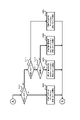
次に図2及び図5に基づいて、本パチンコ遊技機1における電気的な構成を説明する。本実施例のパチンコ遊技機1は、特別図柄当否判定や普通図柄当否判定や遊技状態の移行など、遊技進行や遊技利益に関する制御を行う主制御基板80(「主制御部」ともいい「遊技制御部」ともいう)、遊技の進行に伴って実行する演出に関する制御を行うサブ制御基板90(「サブ制御部」ともいい「演出制御部」ともいう)、遊技球の払い出しに関する制御を行う払出制御基板110(「払出制御部」ともいう)、画像表示装置71,72の表示制御を行う画像制御基板100(画像制御部)等を備えている。
Next, the electrical configuration of the
また、図2に示すように、パチンコ遊技機1の裏面側の略中央部には主制御基板80を収納した主制御基板収納ケースが設けられ、この主制御基板ケースの上方には、音声制御基板106、ランプ制御基板107及び画像制御基板100を収納した画像制御基板等収納ケースが設けられ、その画像制御基板等収納ケース上にはサブ制御基板90を収納したサブ制御基板収納ケースが設けられている。また、主制御基板ケースの下方左側には、払出制御基板を収納する払出制御基板ケースが設けられ、その右側には、電源基板109を収納する電源基板ケースが設けられている。電源基板109は、外部からの供給電力を受けて本パチンコ遊技機1に電力を供給するもので、具体的には、図5のブロック図に示された各種の基板類や装置・機器類、センサ、スイッチ、モータ、ソレノイドなど、本パチンコ遊技機1の動作に必要となる様々な電気部品に電力を供給する。電源基板109のことを「電力供給手段」ともいう。
In addition, as shown in FIG. 2, a main control board housing case containing a
主制御基板80には、プログラムに従ってパチンコ遊技機1の遊技の進行を制御する遊技制御用ワンチップマイコン(以下「遊技制御用マイコン」)81が実装されている。遊技制御用マイコン81には、遊技の進行を制御するためのプログラム等を記憶したROM、ワークメモリとして使用されるRAM、ROMに記憶されたプログラムを実行するCPUが含まれている。遊技制御用マイコン81は、入出力回路87(I/Oポート部)を介して他の基板等とデータ(情報)の送受信を行う。入出力回路87は、遊技制御用マイコン81に内蔵されていてもよい。また、ROMは外付けであってもよい。遊技制御用マイコン81のRAMには、前述した特図保留記憶部(第1特図保留記憶部及び第2特図保留記憶部)と普図保留記憶部とが設けられている。また、主制御基板80(遊技制御用マイコン81)のRAM(主制御RAM)の所定アドレスには、各種フラグや各種計数カウンタに用いるための記憶領域が確保されている。
The
主制御基板80には、中継基板88を介して各種センサやソレノイドが接続されている。そのため、主制御基板80には各センサから信号が入力され、各ソレノイドには主制御基板80から信号が出力される。具体的にはセンサ類としては、第1始動口センサ20a、第2始動口センサ21a、ゲートセンサ28a、第1大入賞口センサ30a、第2大入賞口センサ35a、特定領域センサ39a、非特定領域センサ49aおよび一般入賞口センサ27aが接続されている。これら各種センサを「遊技球検知手段」ともいう。
Various sensors and solenoids are connected to the
第1始動口センサ20aは、第1始動口20内に設けられて第1始動口20に入球した遊技球を検知するものである。第2始動口センサ21aは、第2始動口21内に設けられて第2始動口21に入球した遊技球を検知するものである。ゲートセンサ28aは、ゲート28内に設けられてゲート28を通過した遊技球を検知するものである。第1大入賞口センサ30aは、第1大入賞口30内に設けられて第1大入賞口30に入球した遊技球を検知するものである。第2大入賞口センサ35aは、第2大入賞口35内に設けられて第2大入賞口35に入球した遊技球を検知するものである。特定領域センサ39aは、第2大入賞口35内の特定領域39に設けられており、特定領域39を通過した遊技球を検知するものである。非特定領域センサ49aは、第2大入賞口35内の非特定領域(図示せず)に設けられており、第2大入賞口35に入球した遊技球のうち非特定領域を通過した遊技球(つまり、特定領域39を通過しなかった遊技球)を検知するものである。一般入賞口センサ27aは、各一般入賞口27内にそれぞれ設けられて一般入賞口27に入球した遊技球を検知するものである。
The first
またソレノイド類としては、第2始動口ソレノイド24、第1大入賞口ソレノイド33および第2大入賞口ソレノイド38が接続されている。第2始動口ソレノイド24は、可変入賞装置22の可動部材23を駆動するためのものである。第1大入賞口ソレノイド33は、第1大入賞装置31の開閉部材32を駆動するためのものである。第2大入賞口ソレノイド38は、第2大入賞装置36の開閉部材37を駆動するためのものである。
As the solenoids, the
さらに主制御基板80には、第1特別図柄表示器41a、第2特別図柄表示器41b、普通図柄表示器42、第1特図保留表示器43a、第2特図保留表示器43b、普図保留表示器44、ラウンド表示器45、遊技状態表示器46、発射方向表示器47および当り表示器48が接続されている。すなわち、これらの主表示器40の表示制御は、遊技制御用マイコン81によりなされる。
Furthermore, the
また主制御基板80は、払出制御基板110に主として賞球の払い出しに係るコマンド(賞球払出コマンド等)を送信するとともに、払出制御基板110から払い出しの監視に係る各種コマンド(払出異常検出コマンド等)を受信する。つまり、主制御基板80と払出制御基板110とは双方向通信可能に接続されている。払出制御基板110には、賞球や貸球を払い出す払出装置120、及びカードユニット135(パチンコ遊技機1に隣接して設置され、挿入されたプリペイドカード(遊技価値記憶媒体)等に記憶されている情報に基づいて球貸しを可能にするもの)が接続されているとともに、発射制御基板111(「発射制御部」ともいう)を介して発射装置112が接続されている。発射装置112には、発射ハンドル60(図1を参照)が含まれる。発射装置112のハンドル60が遊技者により操作されると、タッチスイッチ114が発射ハンドル60への遊技者の接触を検知し、発射ボリューム115が発射ハンドル60の回転量を検知する。そして、発射ボリューム115の検知信号の大きさに応じた強さで遊技球が発射されるよう発射モータ113が駆動制御されることとなる。尚、本実施例では、発射モータ113の駆動により発射装置112が連続して発射可能な遊技球の数は1分間で約100個となっている。
In addition, the
払出制御基板110は、プログラムに従ってパチンコ遊技機1の遊技球の払い出しを制御する払出制御用ワンチップマイコン116(「払出制御用マイコン」ともいう)が実装されている。払出制御用マイコン116には、遊技球の払い出しを制御するためのプログラム等を記憶したROM、ワークメモリとして使用されるRAM、ROMに記憶されたプログラムを実行するCPUが含まれている。払出制御用マイコン116は、入出力回路117(I/Oポート部)を介して、主制御基板80からの信号(賞球払出コマンド)やカードユニット135からの信号に基づいて、払出装置120の払出モータ121(電気的駆動源)を駆動して賞球や貸球の払い出しを行う。払い出される遊技球は、その計数のため払出センサ122(検知手段)により検知される。入出力回路117は、払出制御用マイコン116に内蔵されていてもよく、ROMは外付けであってもよい。また、払出制御基板110には、下皿満杯センサ62a及び球切れセンサ152が接続されている(図5を参照)。下皿満杯センサ62aは、下皿62に多量の遊技球が貯留されて下皿62が満杯状態になったことを検知するものであり、払出装置120と下皿62とを繋ぐ遊技球通路(図示せず)の下皿62側近傍に設けられている。球切れセンサ152は、払出装置120に供給される遊技球が不足した状態(以下「球切れ状態」ともいう。)になったことを検知するものであり、樋部材151に設けられるものである。
The
ここで、本実施例の払出装置120および樋部材151の概要を図55及び図56に基づいて説明する。払出装置120(払出手段)は、主として、装置ケース125に払出モータ121(電気的駆動源)を収容し、それをカバー部材124(図2を参照)で覆うことにより構成されるものである。図55及び図56では、カバー部材124を取り外した払出装置120(装置ケース125)の内部を示している。装置ケース125には、払出モータ121が所定の収容部に収容されており、払出モータ121の回転軸(駆動軸)には球送り用のスクリュー123が組み付けられている。また、装置ケース125には、賞球や貸球として払い出す遊技球が流下可能な球通路126と、樋部材151からの遊技球を球通路126内に受け入れる受入口127と、払い出された遊技球を払出装置外(装置ケース外)に排出する排出口128とが、上下にわたって一体的に形成されており、排出口128の近傍に払出センサ122が設けられている。払出モータ121はステッピングモータからなるもので、払出モータ121の駆動制御は、図示しない駆動回路(ステッピングモータ用ドライバ回路)を介して払出制御部の制御下で行われる。払出モータ121が停止しているときは、スクリュー123の一部が球通路126側に突出することにより、遊技球は球通路126内を流下することができなくなる。一方、払出モータ121が回転すると、その回転軸に組み付けられたスクリュー123も一緒に回転し、これに伴って球通路126内の遊技球が下方へ送り出され、排出口128から排出される。この排出される(払い出される)遊技球は、払出センサ122により検知されて、上皿61又は下皿62に払い出される。また、払出装置120による遊技球の払い出し(排出)に伴って、樋部材151の内部を遊技球が流下する。一方、樋部材151は、球通路153が形成された樋本体151Aを樋カバー151B(図2を参照)で覆うことにより構成されるものである。図56では、樋カバー151Bを取り外した樋部材151(樋本体151A)の内部を示している。樋本体151Aには、球タンク150から供給される遊技球を払出装置120側に誘導する球通路153が上下方向に一体的に形成されている。球通路153は、その上流側開口が球タンク150(図2を参照)から供給される遊技球が流入する流入口となっており、その下流側開口が払出装置120の受入口127に接続している。球通路153の上下方向の略中間部位には、球切れセンサ152及び検知片154が設けられており、球通路153内の遊技球が不足して中間部位に遊技球が存在しなくなると、検知片154が球通路153側に傾動して球切れセンサ152の検知範囲(検知領域)から外れ、これにより球切れ状態が検知される。
Here, the outline of the
さらに主制御基板80は、サブ制御基板90に対し各種コマンドを送信する。主制御基板80とサブ制御基板90との接続は、主制御基板80からサブ制御基板90への信号の送信のみが可能な単方向通信接続となっている。すなわち、主制御基板80とサブ制御基板90との間には、通信方向規制手段としての図示しない単方向性回路(例えばダイオードを用いた回路)が介在している。
Further, the
また、図5に示すように、サブ制御基板90には、プログラムに従ってパチンコ遊技機1の演出を制御する演出制御用ワンチップマイコン91(「演出制御用マイコン」)が実装されている。演出制御用マイコン91には、遊技の進行に伴って演出を制御するためのプログラム等を記憶したROM、ワークメモリとして使用されるRAM、ROMに記憶されたプログラムを実行するCPUが含まれている。演出制御用マイコン91は、入出力回路95(I/Oポート部)を介して他の基板等とデータの送受信を行う。入出力回路95は、演出制御用マイコン91に内蔵されていてもよい。また、ROMは外付けであってもよい。また、サブ制御基板90(演出制御用マイコン91)のRAM(演出制御RAM)の所定アドレスには、各種フラグや各種計数カウンタに用いるための記憶領域が確保されている。
Further, as shown in FIG. 5, the
サブ制御基板90には、画像制御基板100、音声制御基板106、ランプ制御基板107が接続されている。尚、サブ制御基板90(サブ制御部)や画像制御基板100(画像制御部)、音声制御基板106(音声制御部)、ランプ制御基板107(ランプ制御部)は、遊技の状況に応じて表示演出や音演出、ランプ演出(光演出)等の各種演出を、対応する演出用の装置や部材等(電気部品、演出手段)に実行させる演出実行手段として機能するものである。また、識別情報(特別図柄や演出図柄)の変動表示に関する情報を示唆する種々の予告演出(示唆演出)を、対応する演出用の装置や部材等(電気部品、演出手段)に実行させる予告演出実行手段としても機能する。
An
ここで、予告演出とは、例えば、変動表示の表示結果が大当りとなる可能性(信頼度、期待度)やリーチ演出の実行有無(実行可能性)等、変動表示の表示結果や当該表示結果の導出表示に至るまでの過程に関する情報を事前に示唆する演出(示唆演出)のことをいう。予告演出は、大別すると、特別図柄の保留の事前判定結果に基づく保留に関する予告演出と、実行中の変動表示(変動演出)に関する予告演出に分けられ、前者を「保留先読み予告」ともいい、後者を「当該変動予告」ともいう。本実施例では、これら両方の予告演出を実行することが可能となっている。 Here, the notice effect is, for example, the possibility that the display result of the variable display will be a big hit (reliability, expectation), whether or not the ready-to-win effect is executed (feasibility), and the display result of the variable display and the display result. It refers to a production (suggestive production) that suggests in advance information related to the process leading up to the derivation display of . The notice effect is roughly divided into the notice effect related to the suspension based on the preliminary determination result of the suspension of the special pattern, and the notice effect related to the variable display (variation effect) being executed. The latter is also referred to as "the relevant change notice". In this embodiment, it is possible to execute both of these advance notice effects.
サブ制御基板90の演出制御用マイコン91は、主制御基板80から受信したコマンドに基づいて、画像制御基板100の画像制御用ワンチップマイコン101(「画像制御用マイコン」)のCPUに、下画像表示装置71および上画像表示装置72の表示制御を行わせる。画像制御基板100(画像制御用マイコン101)のRAMは、画像データを展開するためのメモリである。画像制御基板100(画像制御用マイコン101)のROMには、画像表示装置71,72に表示される静止画データや動画データ、具体的にはキャラクタ、アイテム、図形、文字、数字および記号等(演出図柄、保留図柄等を含む)や背景画像等の画像データが格納されている。画像制御用マイコン101は、演出制御用マイコン91からの指令に基づいてROMから画像データを読み出す。そして、読み出した画像データに基づいて表示制御を実行する。尚、画像制御基板100の画像制御用ワンチップマイコン101に換えて、または加えてVDP(Video Display Processor)を設けてもよい。
The
また、演出制御用マイコン91は、主制御基板80から受信したコマンドに基づいて、音声制御基板106を介してスピーカ67から音声、楽曲、効果音等を出力する。スピーカ67から出力する音声等の音響データは、サブ制御基板90のROMに格納されている。尚、音声制御基板106にCPUを実装してもよく、その場合、そのCPUに音声制御を実行させてもよい。さらにこの場合、音声制御基板106にROMを実装してもよく、そのROMに音響データを格納してもよい。また、スピーカ67を画像制御基板100に接続し、画像制御用マイコン101に音声制御を実行させてもよい。さらにこの場合、画像制御基板100のROMに音響データを格納してもよい。
Also, the
さらに、演出制御用マイコン91は、主制御基板80から受信したコマンドに基づいて、枠ランプ66や盤面ランプ5等のランプの発光態様を決める発光パターンデータ(点灯/消灯や発光色等を決めるデータ、ランプデータともいう)を、ROMに格納されているデータから決定し、ランプ制御基板107を介して枠ランプ66や盤面ランプ5等のランプ(LED)の点灯制御を行う。
Furthermore, the
また、演出制御用マイコン91は、主制御基板80から受信したコマンドに基づいて、ランプ制御基板107に中継基板108を介して接続された枠可動装飾部材13や盤可動装飾部材14を動作させる。前述したように、枠可動装飾部材13は前面枠51に設けられ、盤可動装飾部材14はセンター装飾体10に設けられた、可動式のいわゆるギミックのことである。尚、枠可動装飾部材13のことを「枠可動役物」ともいい、盤可動装飾部材14のことを「盤可動役物」ともいい、枠可動装飾部材13(枠可動役物)および盤可動装飾部材14(盤可動役物)を総じて「可動装飾部材」や「可動役物」ともいう。
In addition, the
演出制御用マイコン91は、可動装飾部材(枠可動装飾部材13、盤可動装飾部材14)を所定の駆動態様(動作態様)で駆動(動作)させるための駆動パターンデータ(「駆動データ」ともいう)を、サブ制御基板90のROMに格納されているデータから決定し、ランプ制御基板107および中継基板108を介して可動装飾部材の駆動制御を行う。尚、ランプ制御基板107にCPUを実装してもよく、この場合、そのCPUにランプの点灯制御(LED駆動制御)や可動装飾部材の駆動制御を実行させてもよい。さらにこの場合、ランプ制御基板107にROMを実装してもよく、そのROMに発光パターンや駆動パターンに関するデータを格納してもよい。
The
また、サブ制御基板90には、第1演出ボタン63aまたは第2演出ボタン63b(図1参照)が操作(押す、回転、引く等)されたことを検知する第1演出ボタン検知スイッチ63cおよび第2演出ボタン検知スイッチ63dが接続されている。従って、第1演出ボタン63aまたは第2演出ボタン63bに対して遊技者が所定の入力操作を行うと、対応する演出ボタン検知スイッチからサブ制御基板90に対して信号が出力される。尚、第1演出ボタン検知スイッチ63cおよび第2演出ボタン検知スイッチ63dを総称して単に「演出ボタン検知スイッチ」ともいう。
Also, the
ここで、サブ制御基板90(演出制御用マイコン91)は、可動装飾部材13,14や盤面ランプ5、枠ランプ66等の演出用の電気部品の駆動制御を行う「駆動制御手段」として機能するものである。また、画像制御基板100(画像制御用マイコン101)は、画像表示装置71,72(演出用の電気部品の一種)の駆動制御を行う「駆動制御手段」として機能するものである。
Here, the sub-control board 90 (the effect control microcomputer 91) functions as a "drive control means" that controls the driving of the electric parts for effect such as the movable
次に、本実施例のパチンコ遊技機1における当否判定に係る制御(判定手段)について説明する。特別図柄当否判定の結果として、「大当り」、「小当り」、「外れ」がある。特別図柄当否判定の結果が「大当り」のときには、特別図柄表示部41に「大当り図柄」が停止表示され、「小当り」のときには、特別図柄表示部41に「小当り図柄」が停止表示され、「外れ」のときには、特別図柄表示部41に「外れ図柄」が停止表示される。大当り又は小当りと判定されると、停止表示された特別図柄の種類に応じた開放パターンにて、第1大入賞口30又は第2大入賞口35を開放する「特別遊技」が実行される。大当りとなって実行される特別遊技を「大当り遊技」といい、小当りとなって実行される特別遊技を「小当り遊技」という。
Next, the control (determining means) relating to the winning/losing determination in the
当りには複数の種別がある。図6に示すように大当りの種別としては、「15R(ラウンド)第1大当り」、「15R第2大当り」、「15R第3大当り」、「2R第4大当り」、「15R第5大当り」および「15R第6大当り」がある。「15R第1大当り」および「15R第5大当り」は、大入賞口(第1大入賞口30又は第2大入賞口35)の開放回数(ラウンド数)が15回であり、1ラウンド目と2ラウンド目に、特定領域39への遊技球の通過(V通過)が可能(容易)な態様で第2大入賞口35を開放させる大当りである。この特定領域39への遊技球の通過を狙うラウンドを「Vラウンド」や「チャンスラウンド」ともいう。
There are multiple types of hits. As shown in FIG. 6, the types of jackpots are "15R (round) 1st jackpot", "15R 2nd jackpot", "15R 3rd jackpot", "2R 4th jackpot", "15R 5th jackpot" and There is a "15R 6th jackpot". In the "15R 1st jackpot" and "15R 5th jackpot", the number of openings (number of rounds) of the big winning opening (1st big winning
「15R第2大当り」、「15R第3大当り」および「15R第6大当り」は、大入賞口(第1大入賞口30又は第2大入賞口35)の開放回数(ラウンド数)が15回であるものの、前述のVラウンドである1ラウンド目と2ラウンド目の開放時間が極短時間(一瞬開閉)で、特定領域39への遊技球の通過が困難(不可能としてもよい)な大当りである。すなわち、これらの大当りは、特定領域39への遊技球の通過が可能(容易)な態様で第2大入賞口35を開放させることのない大当りであるといえる。
"15R 2nd jackpot", "15R 3rd jackpot" and "15R 6th jackpot" are opened 15 times (number of rounds) of the big prize gate (first
「2R第4大当り」は、大入賞口(第1大入賞口30または第2大入賞口35)の開放回数(ラウンド数)が2回であり、Vラウンドである1ラウンド目と2ラウンド目に特定領域39への遊技球の通過が可能な態様で第2大入賞口35を開放させる大当りである。但し、第2大入賞口35の開放時間が1ラウンド目と2ラウンド目を合わせても1.8秒であるので、15R第1大当りより特定領域への遊技球の通過可能性が低いものとなっている。
"2R 4th jackpot" is that the number of openings (number of rounds) of the big winning opening (first big winning
本実施例のパチンコ遊技機1では、大当り遊技中の特定領域39への遊技球の通過に基づいて、その大当り遊技の終了後の遊技状態を、後述の高確率状態に移行させる。従って、特別図柄当否判定の結果が15R第1大当り又は15R第5大当りとなった場合には、特定領域39への遊技球の通過可能性が極めて高い態様で1ラウンド目と2ラウンド目のVラウンドが実行されるため、当該大当り遊技の実行中に特定領域39へ遊技球を通過させることで、大当り遊技後の遊技状態を高確率状態に移行させることができる。また、特別図柄当否判定の結果が2R第4大当りとなった場合には、15R第1大当りや15R第5大当りほどではないものの特定領域39への遊技球の通過可能性がある態様で1ラウンド目と2ラウンド目のVラウンドが実行されるため、当該大当り遊技の実行中に特定領域39へ遊技球を通過させることができれば、大当り遊技後の遊技状態を高確率状態に移行させることができる。
In the
これに対して、特別図柄当否判定の結果が15R第2大当り、15R第3大当り又は15R第6大当りとなった場合には、1ラウンド目と2ラウンド目のVラウンドの開放時間が各0.1秒であるので、第2大入賞口へ遊技球を入球させるのが非常に困難であるので、当該大当り遊技の実行中における特定領域39への遊技球の通過可能性は極めて低くなり(実質的に不可能となり)、その大当り遊技後の遊技状態は、後述の通常状態(低確率状態)となる可能性が非常に高い(低確率状態になるといってもよい)。 On the other hand, when the result of special symbol suitability determination is 15R 2nd jackpot, 15R 3rd jackpot or 15R 6th jackpot, opening times of V rounds of 1st round and 2nd round are 0.00. Since it is 1 second, it is very difficult to let the game ball enter the second big winning hole. It becomes substantially impossible), and the game state after the jackpot game is very likely to be a normal state (low probability state) described later (it can be said to be a low probability state).
一方、小当り(第1小当り、第2小当り)は、見かけ上2R第4大当りと同じ開放パターンで大入賞口(第2大入賞口35)を開放させる当りである。すなわち小当りでは、特定領域39への遊技球の通過が可能な態様で第2大入賞口35を開放させる。しかしながら、小当り遊技の実行中に特定領域39への遊技球の通過があったとしても、小当り遊技の実行後の遊技状態は小当り遊技の実行前から変化しないものとなっている。そのため、小当り遊技の実行前の遊技状態が通常状態(低確率状態)であれば、小当り遊技の実行後の遊技状態も通常状態となる。そして遊技者から見れば、上記の2R第4大当りと小当りとは大入賞口(第2大入賞口35)の開放パターンを見ても区別することができない。すなわち遊技者は特別図柄当否判定の結果が「2R第4大当り」になったのか「小当り」になったのかを認識するのが困難である。そのため、2R第4大当りとしての特別遊技中(大当り遊技中)に遊技球が特定領域39を通過したとしても、それだけでは、その後の遊技状態が高確率状態に移行したかどうかを認識するのは困難である。また、小当りとしての特別遊技中(小当り遊技中)に遊技球が特定領域39を通過したとしても、それだけでは、その後の遊技状態が通常状態のままか、高確率状態に移行したかを認識するのは困難である。その結果、小当りとなった場合および2R第4大当りになった場合には、高確率状態であるかもしれないという期待感を持ちつつ遊技を進行することができ、遊技興趣を高めることができる。尚、小当りにおいては大入賞口の開放回数をラウンド数とはいわず、単に開放回数という。
On the other hand, a small win (first small win, second small win) is a win to open a big winning hole (second big winning hole 35) in the same opening pattern as the 2R fourth big win. That is, in the small hit, the second big winning
本実施例のパチンコ遊技機1における各大当り及び小当りとなったときの大入賞口の開放パターンは、図6のようになっている。すなわち、15R第1大当りとなった場合(第1特別図柄表示器41aに15R第1大当り図柄が停止表示された場合)および15R第5大当りとなった場合(第2特別図柄表示器41bに15R第5大当り図柄が停止表示された場合)には、1R~2Rでは第2大入賞口35を最大28秒開放させ、3R~15Rでは第1大入賞口30を最大28秒開放させる。この当りでは、1R目と2R目における第2大入賞口35の開放時間が夫々28秒あるため、そのラウンド中(Vラウンド中)に遊技球が特定領域39を通過する可能性は極めて高いものとなっている。
FIG. 6 shows the opening patterns of the big winning openings when each big win and small win are achieved in the
また、15R第2大当りとなった場合(第1特別図柄表示器41aに15R第2大当り図柄が停止表示された場合)と、15R第3大当りとなった場合(第1特別図柄表示器41aに15R第3大当り図柄が停止表示された場合)と、15R第6大当りとなった場合(第2特別図柄表示器41bに15R第6大当り図柄が停止表示された場合)には、1R~2Rでは第2大入賞口35を最大0.1秒開放させ、3R~15Rでは第1大入賞口30を最大28秒開放させる。この当りでは、1R目と2R目における第2大入賞口35の開放時間が夫々最大0.1秒と極短時間とされている(一瞬開閉)ため、そのラウンド中(Vラウンド中)に遊技球が特定領域39を通過することはほぼ不可能となっている。
Also, when it becomes a 15R second big hit (when the 15R second big hit symbol is stopped and displayed on the first
このように、本実施例では、15R第2,第3,第6大当り用の開放パターンと、15R第1,第5大当り用の開放パターンと比べて第1ラウンドおよび第2ラウンド(Vラウンド)とでは、開放態様が異なっている。そして、15R第1,第5大当りでは、1ラウンド目と2ラウンド目に第2大入賞口35が28秒開放するため、当該Vラウンドでは、球詰まりや遊技球発射系のトラブル等が発生しない限り、略確実に遊技球が第2大入賞口35に入球して、高い確率で特定領域39を通過することとなる。これに対して、15R第2,第3,第6大当りでは、1ラウンド目と2ラウンド目に第2大入賞口35が0.1秒しか開放しない。そのため、第2大入賞口35に遊技球が入球することは非常に困難である。従って、15R第2,第3,第6大当りに係る大当り遊技の実行中に遊技球が特定領域39を通過する可能性は、15R第1,第5大当りと比してかなり低くなっており、実質的には通過不可能といってもよい。
Thus, in this embodiment, compared with the opening patterns for the 15R second, third and sixth jackpots and the opening patterns for the 15R first and fifth jackpots, the first round and the second round (V round) are different in opening mode. In the 15R 1st and 5th jackpots, the second big prize-winning
尚、特定領域39への遊技球の通過可能性(V通過可能性)が極めて高い態様でVラウンドが実行される大当りのことを「V通過予定大当り」ともいい、V通過可能性が極めて低い態様でVラウンドが実行される大当りのことを「V非通過予定大当り」ともいう。 A jackpot in which the V round is executed in a manner in which the possibility of the game ball passing through the specific area 39 (V passing possibility) is extremely high is also called a "V passing scheduled jackpot", and the V passing possibility is extremely low. A jackpot in which V rounds are executed in the mode is also referred to as a "V non-passing scheduled jackpot".
また、図6に示すように、2R第4大当りとなった場合(第1特別図柄表示器41aに2R第4大当り図柄が停止表示された場合)には、1R~2Rまで第2大入賞口35を最大0.9秒開放させる。この当りでは、1R目と2R目の第2大入賞口35の開放時間の合計が最大で1.8秒となるため、そのラウンド中に遊技球を第2大入賞口35に入球させて特定領域39を通過させることが可能となっている。本実施例の本パチンコ遊技機1においては、0.6秒程度で1個の遊技球が発射されるようになっているので、第2大入賞口35の開放時間が1.8秒あれば、第2大入賞口35へ遊技球を入球させて特定領域39への遊技球の通過を狙うことは十分に可能である。但し、2R第4大当りは、第2大入賞口の総開放時間が1.8秒と短いため、他の15R大当りのように多くの賞球(遊技利益)を望めるものではない。すなわち他の大当りに比してほとんど賞球の獲得できない大当りである。
In addition, as shown in FIG. 6, when the 2R fourth big win is achieved (when the 2R fourth big win symbol is stopped and displayed on the first
また、第1小当りとなった場合(第1特別図柄表示器41aに第1小当り図柄が停止表示された場合)と、第2小当りとなった場合(第2特別図柄表示器41bに第2小当り図柄が停止表示された場合)には、第2大入賞口35の最大0.9秒間の開放を2回行う。すなわち、2R第4大当りと同じ開放パターンにて大入賞口を開放させる。この小当りにおいても、第2大入賞口35の開放時間が合計1.8秒あるため、遊技球を第2大入賞口35に入球させて特定領域39を通過させることが可能となっている。しかし、前述の通り、小当り遊技にて特定領域39への通過があっても、小当り遊技の前後で遊技状態の変化はない。また、小当り遊技では、大入賞口の総開放時間が1.8秒と短いため、2R第4大当りと同様に多くの賞球を望めるものではない。すなわち小当りは、遊技状態の移行という点についても、賞球という点についても、遊技者にとっての特典がほぼ無いもの(入球による賞球のみ)となっている。
In addition, when it becomes the first small hit (when the first small hit symbol is stopped and displayed on the first special
本実施例では、第2大入賞口35の開放パターンとして、遊技球が特定領域39を通過可能(通過容易)な第1の開放パターンと(15第1大当り、15R第5大当り)、遊技球が特定領域39を通過困難(通過不能)な第2の開放パターンと(15R第2大当り、15R第3大当り、15R第6大当り)、遊技球が特定領域を通過可能であって第1の開放パターンより通過可能性が低い第3の開放パターンと(2R第4大当り)、を有するものとすることができる。また、小当り用の開放パターンとして、遊技球が特定領域39を通過可能であるが通過した場合であっても特典を付与しない(高確率状態を発生しない)第4の開放パターンを有するものとすることができる。この第4の開放パターンは、他の態様として特定領域39を通過不能な開放パターンとしてもよい。
In this embodiment, as the opening pattern of the second big winning
尚、第1特別図柄(特図1)の当否判定における各大当りへの振分確率は、15R第1大当りが40%、15R第2大当りが20%、15R第3大当りが30%、2R第4大当りが10%となっている(図6の大当り種別決定用乱数の欄を参照)。これに対して、第2特別図柄(特図2)の当否判定における大当りは、15R第5大当りが80%、15R第6大当りが20%となっている(図6の大当り種別決定用乱数の欄を参照)。この振分確率は、大当り遊技中に遊技球が特定領域39を通過する可能性、すなわち高確率状態となる確率を表しているものといえ、また、後述の開放延長機能が作動する高ベース状態となる確率を表しているものといえる。
In addition, the distribution probability to each jackpot in the judgment of the first special pattern (special drawing 1) is 40% for the 15R first jackpot, 20% for the 15R second jackpot, 30% for the 15R third jackpot, and 30% for the 2Rth jackpot. 4 jackpots are 10% (see the column of random numbers for jackpot type determination in FIG. 6). On the other hand, the big hits in the success/failure determination of the second special symbol (special figure 2) are 80% for the 5th big hit on the 15R and 20% for the 6th big hit on the 15R. column). This distribution probability can be said to represent the possibility of the game ball passing through the
すなわち、高確率状態となる確率については、第1始動口20への入球に基づく当否判定(第1特別図柄当否判定)で大当りとなった場合、その確率は少なくとも40%となっており、2R第4大当りに係る大当り遊技中に遊技球が特定領域39を通過する場合を含めると、その確率は50%となっている。一方、第2始動口21への入球に基づく当否判定(第2特別図柄当否判定)で大当りとなった場合、その確率は80%となっている。
That is, with respect to the probability of becoming a high probability state, if the success judgment (first special symbol success judgment) based on the ball entering the
また、高ベース状態となる確率については、開放延長機能が作動していない遊技状態(低ベース状態)において第1特別図柄当否判定で大当りとなった場合、その確率は60%となっており、高ベース状態において第1特別図柄当否判定で大当りとなった場合の2R第4大当りを含めると、その確率は70%となっている。一方、第2特別図柄当否判定で大当りとなった場合、その確率は100%となっている。そして、第2特別図柄当否判定で大当りとなった場合には、第1特別図柄当否判定で大当りとなった場合に発生し得る2R大当りが発生することはなく、必ず15R大当りとなる。 In addition, regarding the probability of becoming a high base state, if the game state (low base state) in which the opening extension function is not activated, the probability is 60% when the first special symbol success/failure determination results in a big hit. The probability is 70% including the 2R fourth jackpot when the first special symbol propriety determination results in a jackpot in the high base state. On the other hand, when the second special symbol propriety determination results in a big hit, the probability is 100%. When a big win is achieved in the second special symbol suitability determination, the 2R big win that can occur when the first special symbol suitability determination results in a big win does not occur, and the 15R big win is always achieved.
このように本実施例のパチンコ遊技機1では、第1始動口20に遊技球が入球して行われる第1特別図柄当否判定(第1特別図柄の大当り抽選)において大当りとなるよりも、第2始動口21に遊技球が入球して行われる第2特別図柄当否判定(第2特別図柄の大当り抽選)において大当りとなる方が、第1特別図柄当否判定で大当りとなる場合に比べ、高確率状態になる確率や高ベース状態になる確率、さらには15R分の賞球を獲得できる可能性が高くなっている。つまり、第2特別図柄当否判定で大当りとなる場合の方が、第1特別図柄当否判定で大当りとなる場合に比べ、遊技者にとって有利となる可能性が高くなるように設定されており、第2特別図柄を変動表示させた方が、第1特別図柄を変動表示させるよりも遊技者にとって有利に働く可能性が高いものとなっている。このため、遊技者は、第2始動口21への入球を期待して遊技を行うこととなる。特に第2始動口21への入球頻度が高まる開放延長機能の作動中(高ベース状態)においては顕著である。尚、前述の振分確率は一例であり、遊技性やスペック等を考慮して任意に設定することができる。
Thus, in the
また、本実施例では、第2特別図柄を第1特別図柄に比して優位にしていることから、第1特別図柄の変動表示と第2特別図柄の変動表示が共に実行可能な場合、すなわち、第1特図保留と第2特図保留が共に「1」以上存在する場合には、第2特別図柄の変動表示(第2特図保留の消化)を第1特別図柄の変動表示(第1特図保留の消化)に優先して行うものとしている。これにより、第2始動口21への入球頻度が高まる高ベース状態は、第2特別図柄の変動表示の実行頻度が高まるので、遊技者にとって有利に遊技を進めることが可能な状態といえる。にもかかわらず、高ベース状態で第1特別図柄の変動表示が行われることは、遊技者にとっては、せっかくの有利な状態(高ベース状態)での遊技に水を差されることとなり、第1特別図柄の変動表示は第2特別図柄の変動表示に比べ不利に働く可能性もあることから、高ベース状態での第1特別図柄の変動表示は、遊技者にとって望ましいことではないといえる。
Also, in this embodiment, since the second special symbol is superior to the first special symbol, if both the first special symbol variable display and the second special symbol variable display are executable, that is, , If both the first special symbol reservation and the second special symbol reservation are "1" or more, the variation display of the second special symbol (digestion of the second special symbol reservation) is changed to the first special symbol variation display (second 1 digestion of special figure reservation) will be given priority. As a result, the high base state in which the frequency of ball entry into the
ここで、特別図柄の停止表示の態様として、大当り図柄のことを「特定態様」や「特定表示結果」ともいい、小当り図柄のことを「所定態様」や「所定表示結果」ともいい、外れ図柄のことを「非特定態様」や「非特定表示結果」ともいう。また、高ベース状態の設定契機とならない大当り図柄(15R第3大当り図柄、低ベース状態での2R第4大当り図柄)のことを「第1特定態様」や「第1特定表示結果」ともいい、高ベース状態の設定契機となる大当り図柄(15R第1,第2,第5,第6大当り図柄、高ベース状態での2R第4大当り図柄)のことを「第2特定態様」や「第2特定表示結果」ともいう。また、特別図柄が変動表示する際の遊技状態として、開放延長機能が作動しない遊技状態(低ベース状態)のことを「第1遊技状態」ともいい、開放延長機能が作動する遊技状態(高ベース状態)のことを「第2遊技状態」ともいう。 Here, as the mode of the stop display of the special symbols, the big hit symbol is also called "specific mode" or "specific display result", and the small winning symbol is also called "predetermined mode" or "predetermined display result". The pattern is also called "non-specific mode" or "non-specific display result". In addition, the jackpot pattern (15R 3rd jackpot pattern, 2R 4th jackpot pattern in low base state) that does not trigger the setting of the high base state is also called "first specific mode" or "first specific display result". The "second specific mode" or "second Also referred to as “specific display result”. In addition, as a game state when the special symbols are variably displayed, the game state (low base state) in which the open extension function does not operate is also called a "first game state", and the game state in which the open extension function operates (high base state) state) is also referred to as a "second game state".
本パチンコ遊技機1では、大当りか、小当りか、外れかの判定は「特別図柄当否判定用乱数(「当否判定用情報」ともいう)」に基づいて行われ、大当りとなった場合の大当りの種別の判定は「大当り種別決定用乱数(「図柄決定用乱数」、「図柄決定用情報」ともいう)」に基づいて行われる。図7(A)に示すように、特別図柄当否判定用乱数は「0~629」までの範囲で値をとり、大当り種別決定用乱数は「0~99」までの範囲で値をとる。また、第1始動口20や第2始動口21への入球に基づいて取得される乱数(取得情報)には、特別図柄当否判定用乱数および大当り種別決定用乱数の他に「変動パターン乱数(「変動パターン情報」ともいう)」がある。変動パターン乱数は、変動時間を含む変動パターンを決めるための乱数であり、「0~198」までの範囲で値をとる。また、ゲート28の通過に基づいて取得される乱数には、図7(B)に示す普通図柄当否判定用乱数がある。普通図柄当否判定用乱数は、第2始動口21を開放させる補助遊技を行うか否かの判定(普通図柄抽選)のための乱数であり、「0~240」までの範囲で値をとる。
In this
次に、本実施例のパチンコ遊技機1の遊技状態について説明する。パチンコ遊技機1は、特別図柄に対する確率変動機能、普通図柄に対する確率変動機能、変動時間短縮機能および開放延長機能の各機能が作動状態または非作動状態となる組合せにより、複数の遊技状態を有している。特別図柄(第1特別図柄および第2特別図柄)について確率変動機能が作動している状態を「高確率状態」といい、作動していない状態を「通常状態(「低確率状態」ともいう)」という。高確率状態では、特別図柄当否判定において大当りと判定される確率が通常状態よりも高くなっている。すなわち、通常状態では通常状態用の当り判定テーブルを用いて当否判定を行い、高確率状態では、大当りと判定される特別図柄当否判定用乱数の値が通常状態よりも多い高確率状態用の当り判定テーブルを用いて当否判定を行う(図8(A)を参照)。つまり、特別図柄の確率変動機能が作動すると、作動していないときに比して、特別図柄の変動表示の表示結果が大当りとなる(停止図柄が大当り図柄となる)確率が高くなる。
Next, the game state of the
また、特別図柄(第1特別図柄及び第2特別図柄)について変動時間短縮機能が作動している状態を「時短状態」といい、作動していない状態を「非時短状態」という。時短状態では、特別図柄の変動時間(変動表示の開始時から確定表示時までの時間)の平均値が、非時短状態における特別図柄の変動時間の平均値よりも短くなる。すなわち、時短状態においては、変動時間の短い変動パターンが選択されることが非時短状態よりも多くなるように定められた変動パターンテーブルを用いて、変動パターンの判定を行う(図9を参照)。その結果、時短状態では、特図保留の消化ペースが速くなり、始動口への有効な入球(特図保留として記憶され得る入球)が発生しやすくなる。そのため、スムーズな遊技の進行のもとで大当りを狙うことができる。 In addition, the state in which the variable time reduction function is operating for the special symbols (the first special symbol and the second special symbol) is called "time saving state", and the state in which it is not operating is called "non-time saving state". In the time saving state, the average value of the special symbol variation time (the time from the start of the variable display to the time of the final display) is shorter than the average value of the special symbol variation time in the non-time saving state. That is, in the time saving state, the variation pattern is determined using a variation pattern table that is determined so that a variation pattern with a short variation time is selected more than in a non-time saving state (see FIG. 9) . As a result, in the time-saving state, the pace of digestion of the special figure reservation becomes faster, and an effective entry into the starting port (an entry that can be remembered as a special figure reservation) is more likely to occur. Therefore, it is possible to aim for a big hit under the smooth progress of the game.
特別図柄(第1特別図柄及び第2特別図柄)についての確率変動機能と変動時間短縮機能は同時に作動することもあるし、片方のみが作動することもある。そして、普通図柄についての確率変動機能および変動時間短縮機能は、特別図柄の変動時間短縮機能に同期して作動するようになっている。すなわち、普通図柄の確率変動機能および変動時間短縮機能は、特別図柄の時短状態において作動し、非時短状態において作動しない。よって、時短状態では、普通図柄当否判定における当り確率が非時短状態よりも高くなっている。すなわち、当りと判定される普通図柄乱数(当り乱数)の値が非時短状態で用いる普通図柄当り判定テーブルよりも多い普通図柄当り判定テーブルを用いて、普通図柄当否判定(普通図柄の判定)を行う(図8(C)を参照)。つまり、普通図柄についての確率変動機能が作動すると、作動していないときに比して、普通図柄の変動表示の表示結果が当りとなる(停止図柄が普通当り図柄となる)確率が高くなる。 The probability variation function and the variation time shortening function for the special symbols (the first special symbol and the second special symbol) may operate simultaneously, or only one of them may operate. Then, the probability variation function and the variation time shortening function for the normal symbols operate in synchronization with the variation time shortening function for the special symbols. That is, the normal symbol probability variation function and variation time reduction function operate in the time-saving state of the special symbol, and do not operate in the non-time-saving state. Therefore, in the time-saving state, the hit probability in normal design propriety determination is higher than the non-time-saving state. That is, the value of the normal symbol random number (hit random number) determined to be a hit is larger than the normal symbol per determination table used in the non-time saving state, using the normal symbol per determination table, normal symbol success determination (normal symbol determination) (See FIG. 8(C)). In other words, when the probability variation function for normal symbols is activated, the probability that the display result of variable display of normal symbols is a hit (a stopped symbol becomes a normal winning symbol) becomes higher than when it is not activated.
また時短状態では、普通図柄の変動時間が非時短状態よりも短くなっている。本実施例では、普通図柄の変動時間は非時短状態では30秒であるが、時短状態では1秒である(図8(D)を参照)。さらに時短状態では、可変入賞装置22(第2始動口21)の開放時間延長機能が作動し、補助遊技における第2始動口21の開放時間が、非時短状態よりも長くなっている。加えて時短状態では、可変入賞装置22の開放回数増加機能が作動し、補助遊技における第2始動口21の開放回数が非時短状態よりも多くなっている。具体的には、非時短状態において普通図柄当否判定の結果が当りになると、可変入賞装置22(第2始動口21)の可動部材23が0.2秒の開放動作を1回行い、時短状態において普通図柄当否判定の結果が当りになると、可変入賞装置22(第2始動口21)の可動部材23が2.0秒の開放動作を3回行うものとなっている。
In addition, in the time saving state, the fluctuation time of the normal design is shorter than in the non-working time saving state. In this embodiment, the variation time of the normal symbol is 30 seconds in the non-time saving state, but is 1 second in the time saving state (see FIG. 8(D)). Furthermore, in the time saving state, the opening time extension function of the variable winning device 22 (second starting port 21) is activated, and the opening time of the
普通図柄についての確率変動機能および変動時間短縮機能、並びに、可変入賞装置22の開放時間延長機能および開放回数増加機能が作動している状況下では、これらの機能が作動していない場合に比して、第2始動口21が頻繁に開放され、第2始動口21への遊技球の入球頻度が高くなる(「高頻度状態」ともいう)。その結果、発射球数に対する賞球数の割合であるベースが高くなる。従って、これらの機能が作動している状態を「高ベース状態」ともいい、作動していない状態を「低ベース状態」ともいう。高ベース状態では、手持ちの遊技球(持ち球)を大きく減らすことなく大当りを狙うことができる。
Under the circumstances where the probability variation function and variation time reduction function for normal symbols, and the opening time extension function and the opening number increase function of the variable winning
高ベース状態(高頻度状態)は、上記の全ての機能が作動するものでなくてもよい。すなわち、普通図柄についての確率変動機能および変動時間短縮機能、並びに、可変入賞装置22の開放時間延長機能および開放回数増加機能のうち少なくとも一つの機能の作動によって、その機能が作動していないときよりも第2始動口21が開放され易く(入球頻度が高く)なっていればよい。また、高ベース状態は、特別図柄の時短状態に付随せずに独立して制御されるようにしてもよい。この様な高ベース状態を発生する機能を「高ベース発生機能」ということもできる。
A high base state (high frequency state) may not be one in which all of the above functions are activated. That is, by operating at least one of the probability variation function and variation time reduction function for normal symbols, and the opening time extension function and opening number increase function of the variable winning
本実施例のパチンコ遊技機1では、15R第1,第5大当りとなった場合の大当り遊技終了後の遊技状態は、その大当り遊技中に遊技球が特定領域39を通過していれば、特別図柄の高確率状態かつ特別図柄の時短状態かつ高ベース状態となる(図6を参照)。この遊技状態を特に「高確高ベース状態」という。高確高ベース状態は、所定回数(本例では100回)の特別図柄の変動表示が実行されるか、大当りとなって大当り遊技が実行されることにより終了する。
In the
また、15R第2,第6大当りとなった場合の大当り遊技終了後の遊技状態は、その大当り遊技中に遊技球が特定領域39を通過することは極めて困難であることから特別図柄の通常状態となり、これに加えて特別図柄の時短状態かつ高ベース状態となる(図6を参照)。この遊技状態を特に「低確高ベース状態」という。低確高ベース状態は、所定回数(本例では100回)の特別図柄の変動表示が実行されるか、所定回数(本例では100回)の特別図柄の変動表示が実行されるまでに大当りに当選して当該大当りに係る特別遊技(大当り遊技)が実行されることにより終了する。尚、可能性は限りなく低いが、仮に、15R第2,第6大当りに係る大当り遊技中に遊技球が特定領域39を通過した場合には、その大当り遊技終了後の遊技状態は「高確高ベース状態」となる。また、可能性は限りなく低いが、仮に、15R第1,第5大当りに係る大当り遊技中に遊技球が特定領域39を通過しなかった場合には、その大当り遊技終了後の遊技状態は「低確高ベース状態」となる。
In addition, the game state after the end of the jackpot game when the 15R second and sixth jackpots are won is the normal state of the special symbol because it is extremely difficult for the game ball to pass through the
また、15R第3大当りとなった場合の大当り遊技終了後の遊技状態は、その大当り遊技中に遊技球が特定領域39を通過する可能性は極めて低いことから、特別図柄の通常状態となり、これに加えて特別図柄の非時短状態かつ低ベース状態となる(図6を参照)。この遊技状態を特に「低確低ベース状態」という。低確低ベース状態は、本パチンコ遊技機1において基本となる遊技状態、すなわち初期の遊技状態である。尚、可能性は限りなく低いが、仮に、15R第3大当りに係る大当り遊技中に遊技球が特定領域39を通過した場合には、その大当り遊技終了後の遊技状態は、後述の「高確低ベース状態」となる。
In addition, the game state after the end of the jackpot game in the case of the 15R third jackpot is a normal state with special symbols because the possibility of the game ball passing through the
また、低確低ベース状態において、2R第4大当りとなった場合の大当り遊技終了後の遊技状態は、その大当り遊技中に遊技球が特定領域39を通過していれば、特別図柄の高確率状態かつ特別図柄の非時短状態かつ低ベース状態となる(図6を参照)。この遊技状態を特に「高確低ベース状態」という。高確低ベース状態は、所定回数(本例では100回)の特別図柄の変動表示が実行されるか、大当りとなって大当り遊技が実行されることにより終了する。
In addition, in the low-probability-low base state, the game state after the end of the jackpot game when the 2R fourth jackpot is won is a high probability of special symbols if the game ball passes through the
この高確低ベース状態は、高確率状態であることが潜伏している状態、すなわち高確率状態であることが遊技者にとって認識困難な状態である。つまり高確低ベース状態は、いわゆる「潜伏確変状態(「確率非報知状態」ともいう)」である。これに対して、上記の高確高ベース状態は、高確率状態であることが遊技者にとって明らかな状態である。つまり高確高ベース状態は、いわゆる「確変遊技状態」である。 This high-probability-low base state is a state in which the high-probability state is latent, that is, a state in which it is difficult for the player to recognize the high-probability state. That is, the high-probability-low base state is a so-called "latent probability variable state (also referred to as "probability non-announced state")". On the other hand, the above-mentioned high-probability-high base state is a state in which it is clear to the player that it is a high-probability state. In other words, the high probability high base state is the so-called "variable probability gaming state".
また、高ベース状態において、2R第4大当りとなった場合の大当り遊技終了後の遊技状態は、その大当り遊技中に遊技球が特定領域39を通過していれば「高確高ベース状態」となる(図6を参照)。すなわち、特別図柄の時短機能およびベース状態については、大当り遊技の実行前の状態と同じ状態とされる。
In addition, in the high base state, the game state after the end of the jackpot game in the case of the 2R fourth jackpot is "high probability and high base state" if the game ball passes through the
高確高ベース状態や低確高ベース状態といった高ベース状態では、右打ちにより右遊技領域3Rへ遊技球を進入させた方が有利に遊技を進行できる。つまり、高ベース状態は、右打ちで遊技を進行させる右打ち遊技状態でもある。高ベース状態では、低ベース状態と比べて第2始動口21が開放されやすくなっており、第1始動口20への入球よりも第2始動口21への入球の方が容易となっているからである。そのため、高ベース状態では、普通図柄当否判定の契機となるゲート28へ遊技球を通過させつつ、第2始動口21へ遊技球を入球させるべく右打ちを行うことで、左打ちを行うよりも、多数の始動入球(特別図柄当否判定の機会)を得ることができる。この状態のとき、発射方向表示器47が所定の態様で点灯制御され、右遊技領域へ発射すべきことを報知する。尚、高ベース状態では、第2始動口21への入球に基づく第2特別図柄の変動表示(第2特別図柄の当否判定)が主として行われる。但し、高ベース状態であっても、特図2保留球数が「0」であって特図1保留球数が「1」以上の場合には、第1特別図柄の変動表示が行われる。高ベース状態では右打ちを行うため、遊技球が第1始動口20に入球することはなく第1特図保留が新たに記憶されることはまずないが、例えば、大当り発生時(初当り時)に記憶されていた第1特図保留が残っており、その状況下で特図2保留球数が「0」となった場合には、高ベース状態であっても、第1特図保留の消化により第1特別図柄の変動表示が行われる。
In a high-base state such as a high-probability-high base state or a low-probability-high base state, the game can be advantageously progressed by making the game ball enter the
これに対して、高確低ベース状態や低確低ベース状態といった低ベース状態では、左打ちにより左遊技領域3Lへ遊技球を進入させた方が有利に遊技を進行できる。つまり、低ベース状態は、左打ちで遊技を進行させる左打ち遊技状態でもある。低ベース状態では、高ベース状態と比べて第2始動口21が開放されにくくなっており、第2始動口21への入球よりも第1始動口20への入球の方が容易となっているからである。そのため、低ベース状態では、第1始動口20へ遊技球を入球させるべく左打ちを行うことで、右打ちを行うよりも、多数の始動入球(特別図柄当否判定の機会)を得ることができる。この状態のとき、発射方向表示器47が所定の態様で点灯制御(表示制御)され、左遊技領域へ発射すべきことを報知する。尚、低ベース状態では、第1始動口20への入球に基づく第1特別図柄の変動表示(第1特別図柄の当否判定)が主として行われる。但し、低ベース状態であっても、特図2保留球数が「1」以上の場合には、第2特図保留の優先消化に伴い、第2特別図柄の変動表示が行われる。低ベース状態では左打ちを行うため、普通であれば、遊技球が第2始動口21に入球することはなく第2特図保留が新たに記憶されることはまずないが、例えば、遊技状態が高ベース状態(時短状態)から低ベース状態(通常状態)に移行した際に、その移行前の高ベース状態にて記憶された第2特図保留が残っている場合には、低ベース状態であっても、第2特図保留の優先消化に伴い第2特別図柄の変動表示が行われる。
On the other hand, in a low-base state such as a high-probability-low base state or a low-probability-low base state, the game can be advantageously progressed by entering the game ball into the
発射方向表示器47は、「yz」の2個のLEDで構成されており、遊技状態に応じてLEDを点灯させることにより発射方向を示すものである。例えば、低ベース状態では、「y□z□」(例えば、□:消灯、■:点灯とする)というように両LEDを消灯する表示態様として左遊技領域へ発射すべきことを報知することができる。また、高ベース状態では、「y■z■」(例えば、□:消灯、■:点灯とする)というように両LEDを点灯する表示態様として右遊技領域へ発射すべきことを報知することができる。
The
以上のように、本実施例のパチンコ遊技機1においては、小当り遊技や大当り遊技が行われていない低確低ベース状態を基準とすると、この低確低ベース状態を「通常遊技状態」もしくは「通常状態」として捉えることができ、当該状態にて特別図柄を変動表示させる遊技を「通常遊技」として捉えることができる。
As described above, in the
そして、大当り遊技は、特別図柄を変動表示させて大当り図柄が停止表示されることで実行され得る遊技であって、遊技者にとっては、大入賞口(第1大入賞口32、第2大入賞口35)への遊技球の入球により多量の賞球を得ることが可能な有利な遊技であることから、大当り遊技を「特別遊技」として捉えることができ、当該大当り遊技が行われる遊技状態を「特別遊技状態」として捉えることができる。 The jackpot game is a game that can be executed by variably displaying the special symbols and stopping and displaying the jackpot symbols. Since it is an advantageous game that can obtain a large amount of prize balls by entering the game ball into the opening 35), the big win game can be regarded as a "special game", and the game state in which the big win game is performed. can be regarded as a "special game state".
また、小当り遊技は、大当り遊技ほどではないものの、大入賞口(第1大入賞口32、第2大入賞口35)への遊技球の入球により賞球を得ることは可能なので、一応は、通常遊技に比べ遊技者に有利な遊技といえる。よって、小当り遊技も「特別遊技」として捉えることができ、当該小当り遊技が行われる遊技状態も「特別遊技状態」として捉えることができる。尚、大当り遊技としての特別遊技と、小当り遊技としての特別遊技を区別するため、小当り遊技としての特別遊技を「小利益特別遊技」として捉えることもできる。
In addition, although the small winning game is not as good as the big winning game, it is possible to get a prize ball by entering the game ball into the big winning hole (first big winning
[主制御メイン処理]
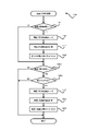
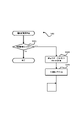
次に、図10~図38に基づいて、遊技制御用マイコン81の動作(主制御部による制御処理)について説明する。尚、遊技制御用マイコン81の動作説明にて登場するカウンタ、フラグ、ステータス、バッファ等は、主制御基板80(遊技制御用マイコン81)のRAMに設けられている。主制御基板80に備えられた遊技制御用マイコン81は、パチンコ遊技機1の電源がオンされると、主制御基板80のROMから図10に示した主制御メイン処理のプログラムを読み出して実行する。同図に示すように、主制御メイン処理では、まず初期設定を行う(S101)。初期設定では例えば、スタックの設定、定数設定、割り込み時間の設定、主制御基板80のCPUの設定、SIO、PIO、CTC(割り込み時間用コントローラ)の設定や、各種のフラグ、ステータス及びカウンタのリセット等を行う。フラグの初期値は「0」つまり「OFF」であり、ステータスの初期値は「1」であり、カウンタの初期値は「0」である。尚、初期設定(S101)は、電源投入後に一度だけ実行され、それ以降は実行されない。
[Main control main processing]
Next, based on FIGS. 10 to 38, the operation of the game control microcomputer 81 (control processing by the main control section) will be described. Incidentally, counters, flags, statuses, buffers, etc. appearing in the explanation of the operation of the
初期設定(S101)に次いで、割り込みを禁止し(S102)、普通図柄・特別図柄主要乱数更新処理(S103)を実行する。この普通図柄・特別図柄主要乱数更新処理(S103)では、図7に示した種々の乱数カウンタの値を1加算する更新を行う。各乱数カウンタの値は上限値に至ると「0」に戻って再び加算される。尚各乱数カウンタの初期値は「0」以外の値であってもよく、ランダムに変更されるものであってもよい。更新された乱数カウンタ値は主制御基板80(遊技制御用マイコン81)のRAMの所定の更新値記憶領域(図示せず)に逐次記憶される。 After the initial setting (S101), interrupts are prohibited (S102), and the normal design/special design main random number update process (S103) is executed. In this normal symbol/special symbol main random number update process (S103), the values of various random number counters shown in FIG. 7 are updated by adding one. When the value of each random number counter reaches the upper limit, it returns to "0" and is added again. The initial value of each random number counter may be a value other than "0", or may be changed randomly. The updated random number counter value is sequentially stored in a predetermined update value storage area (not shown) of the RAM of the main control board 80 (game control microcomputer 81).
普通図柄・特別図柄主要乱数更新処理(S103)が終了すると、割り込みを許可する(S104)。割り込み許可中は、割り込み処理(S105)の実行が可能となる。この割り込み処理(S105)は、例えば4ms周期で主制御基板80のCPUに繰り返し入力される割り込みパルスに基づいて実行される。そして、割り込み処理(S105)が終了してから、次に割り込み処理(S105)が開始されるまでの間に、普通図柄・特別図柄主要乱数更新処理(S103)による各種カウンタ値の更新処理が繰り返し実行される。尚、割り込み禁止状態のときにCPUに割り込みパルスが入力された場合は、割り込み処理(S105)はすぐには開始されず、割り込み許可(S104)がされてから開始される。
When the normal symbol/special symbol main random number update process (S103) ends, the interrupt is permitted (S104). While interrupts are enabled, interrupt processing (S105) can be executed. This interrupt processing (S105) is executed, for example, based on an interrupt pulse that is repeatedly input to the CPU of the
[割り込み処理]
次に、割り込み処理(S105)について説明する。図11に示すように、割り込み処理(S105)では、まず出力処理(S201)を実行する。出力処理(S201)では、以下に説明する各処理において主制御基板80(遊技制御用マイコン81)のRAMに設けられた出力バッファにセットされたコマンド(制御信号)等を、サブ制御基板90や払出制御基板110等に出力する。ここで出力するコマンド等には、遊技状態、特別図柄当否判定の結果、大当り種別としての図柄、変動パターン等に関する情報、賞球として払い出す遊技球の個数(賞球数)に関する情報等が挙げられる。尚、コマンドは、例えば2バイトの情報からなる。上位1バイトは、コマンドの種類に関する情報であり、下位1バイトはコマンドの内容に関する情報である。
[Interrupt processing]
Next, interrupt processing (S105) will be described. As shown in FIG. 11, in the interrupt process (S105), the output process (S201) is first executed. In the output process (S201), the command (control signal) set in the output buffer provided in the RAM of the main control board 80 (game control microcomputer 81) in each process described below, the
出力処理(S201)に次いで行われる入力処理(S202)では、主にパチンコ遊技機1に取り付けられている各種センサ(第1始動口センサ20a、第2始動口センサ21a、第1大入賞口センサ30a、第2大入賞口センサ35a、一般入賞口センサ27a等(図5を参照))が検知した検知信号を読み込み、賞球払出コマンドをRAMの出力バッファに記憶する。また、第1始動口センサ20aや第2始動口センサ21aが遊技球を検知した場合、後述の始動入球時処理(S205)により、各始動口に対応する始動入球コマンドをRAMの出力バッファに記憶する。
In the input process (S202) that follows the output process (S201), various sensors (first starting
ここで、賞球払出コマンドは、遊技領域3(遊技盤面上)に設けられた各種入球口への遊技球の入球に基づく遊技球(賞球)の払い出しを払出制御基板110(払出制御部)に指示するためのコマンドであり、通常、始動口センサや大入賞口センサ等の各種センサによる遊技球1個の検知につき一の賞球払出コマンドがRAMの出力バッファに記憶される。本実施例の賞球払出コマンドには、2個の賞球の払い出しを指示する「賞球2払出コマンド」や、10個の賞球の払い出しを指示する「賞球10払出コマンド」等、賞球として払い出すことが可能な遊技球の数(賞球数)に応じた複数種のコマンドがあり、具体的には「賞球1払出コマンド」~「賞球15払出コマンド」の15種類(15個)のコマンドがある。このため、例えば、第1始動口センサ20aの検知信号の入力があった場合には「賞球4払出コマンド」、第2始動口センサ21aの検知信号の入力があった場合には「賞球2払出コマンド」、大入賞口センサ30a,35aの検知信号の入力があった場合は「賞球15払出コマンド」、一般入賞口センサ27aの検知信号の入力があった場合は「賞球10払出コマンド」が、それぞれ出力バッファに記憶される。また、複数のセンサに係る検知信号の入力が同時期にあった場合や、一のセンサについて検知信号の入力が同時期に複数あった場合には、それら複数の入力に基づく賞球数の合計に応じた賞球払出コマンドが出力バッファに記憶されるものとなっている。具体的に、例えば、第1始動口センサ20aの検知信号(賞球数「4」)及び一般入賞口センサ27aの検知信号(賞球数「10」)の入力が同時期にあった場合には「賞球14払出コマンド」が出力バッファに記憶され、第1大入賞口センサ30aの検知信号(賞球数「15」)の入力が同時期に2回あった場合には2つの「賞球15払出コマンド」が出力バッファに記憶される。但し、複数の入力が同時期にあった場合、それぞれの入力に応じた個々の賞球払出コマンドが出力バッファに記憶されるものであってもよい。
Here, the prize ball payout command is a payout control board 110 (payout control board 110 (payout control Normally, one prize ball payout command is stored in the output buffer of the RAM for each game ball detected by various sensors such as the starting opening sensor and the big winning opening sensor. The prize ball payout command of this embodiment includes a "
次に行われる普通図柄・特別図柄主要乱数更新処理(S203)は、図10の主制御メイン処理で行う普通図柄・特別図柄主要乱数更新処理(S103)と同じである。即ち、図7に示した各種乱数カウンタ値(普通図柄乱数カウンタ値も含む)の更新処理は、タイマ割り込み処理(S105)の実行期間と、それ以外の期間(割り込み処理(S105)の終了後、次の割り込み処理(S105)が開始されるまでの期間)との両方で行われている。 The normal design/special design main random number update process (S203) performed next is the same as the normal design/special design main random number update process (S103) performed in the main control main process of FIG. That is, the updating process of various random number counter values (including the normal symbol random number counter value) shown in FIG. period until the next interrupt process (S105) starts).
普通図柄・特別図柄主要乱数更新処理(S203)に次いで、後述する始動口センサ検知処理(S204)、始動入球時処理(S205)、普図動作処理(S206)、特図動作処理(S207)、特定領域センサ検知処理(S208)、保留球数処理(S209)および電源断監視処理(S210)を実行する。この他、遊技を進行させる上で必要な「その他の処理」を実行して、割り込み処理(S105)を終了する。そして、次に主制御基板80のCPUに割り込みパルスが入力されるまで主制御メイン処理のS102~S104の処理が繰り返し実行され(図10を参照)、割り込みパルスが入力されると(約4msec後)、再び割り込み処理(S105)が実行される。再び実行された割り込み処理(S105)の出力処理(S201)においては、前回の割り込み処理(S105)にてRAMの出力バッファにセットされたコマンド等が出力される。 After the normal design/special design main random number update process (S203), the later-described start opening sensor detection process (S204), start ball time process (S205), normal figure operation process (S206), special figure operation process (S207) , Specific area sensor detection processing (S208), pending ball number processing (S209) and power interruption monitoring processing (S210) are executed. In addition, "other processing" necessary for progressing the game is executed, and the interrupt processing (S105) ends. Then, the processing of S102 to S104 of the main control main processing is repeatedly executed until the next interrupt pulse is input to the CPU of the main control board 80 (see FIG. 10), and when the interrupt pulse is input (after about 4 msec ), and the interrupt process (S105) is executed again. In the output process (S201) of the interrupt process (S105) that is executed again, the commands set in the output buffer of the RAM in the previous interrupt process (S105) are output.
[始動口センサ検知処理]
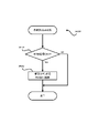
図12に示すように、始動口センサ検知処理(S204)では、まず、遊技球がゲート28を通過したか否か、即ち、ゲートセンサ28aによって遊技球が検知されたか否かを判定する(S301)。遊技球がゲート28を通過していなければ(S301でNO)、S305の処理に移行し、ゲート28を遊技球が通過していれば(S301でYES)、普通図柄保留球数(普図保留の数、具体的にはRAMに設けた普図保留の数をカウントするカウンタの値)が4未満であるか否か判定する(S302)。
[Starting port sensor detection process]
As shown in FIG. 12, in the starting opening sensor detection process (S204), first, it is determined whether or not the game ball has passed through the
普通図柄保留球数が4未満でなければ(S302でNO)、S305の処理に移行する。一方、普通図柄保留球数が4未満であれば(S302でYES)、普通図柄保留球数に「1」を加算し(S303)、普通図柄乱数取得処理(S304)を行う。普通図柄乱数取得処理(S304)では、RAMの更新値記憶領域(図示せず)に記憶されている普通図柄当否判定用乱数カウンタの値(ラベル-TRND-H、図7(B))を取得し、その取得乱数値(取得情報)を、主制御基板80のRAMに設けられた普図保留記憶部のうち現在の普通図柄保留球数に応じたアドレス空間に格納する。
If the number of normal symbol reserved balls is not less than 4 (NO in S302), the process proceeds to S305. On the other hand, if the number of normal design reserved balls is less than 4 (YES in S302), "1" is added to the normal number of reserved design balls (S303), and normal design random number acquisition processing (S304) is performed. In the normal symbol random number acquisition process (S304), the value of the random number counter for normal symbol validity determination (label-TRND-H, FIG. 7(B)) stored in the updated value storage area (not shown) of the RAM is acquired. Then, the acquisition random value (acquisition information) is stored in the address space corresponding to the current number of normal design reservation balls out of the normal design reservation storage section provided in the RAM of the
S305では、第2始動口21に遊技球が入球したか否か、即ち、第2始動口センサ21aによって遊技球が検知されたか否かを判定する(S305)。第2始動口21に遊技球が入球していない場合(S305でNO)には、S309の処理に移行し、第2始動口21に遊技球が入球した場合には(S305でYES)、特図2保留球数(第2特図保留の数、具体的には主制御部80のRAMに設けた第2特図保留の数をカウントするカウンタの数値)が4(上限数)未満であるか否か判定する(S306)。そして、特図2保留球数が4未満でない場合(S306でNO)には、S309の処理に移行し、特図2保留球数が4未満である場合には(S306でYES)、特図2保留球数に1を加算する(S307)。
In S305, it is determined whether or not the game ball has entered the
続いて特図2関係乱数取得処理(S308)を行う。特図2関係乱数取得処理(S308)では、RAMの更新値記憶領域(図示せず)に記憶されている特別図柄当否判定用乱数カウンタの値(ラベル-TRND-A)、大当り種別決定用乱数カウンタの値(ラベル-TRND-AS)及び変動パターン乱数カウンタの値(ラベル-TRND-T1)を取得し(つまり図7(A)に示す乱数の値を取得し)、それら取得乱数値(取得情報)を第2特図保留記憶部85bのうち現在の特図2保留球数に応じたアドレス空間に格納する。 Then special figure 2 relation random number acquisition processing (S308) it does. In the special figure 2 related random number acquisition process (S308), the value of the special symbol propriety determination random number counter (label-TRND-A) stored in the updated value storage area (not shown) of the RAM, the random number for determining the jackpot type Acquire the value of the counter (label-TRND-AS) and the value of the fluctuation pattern random number counter (label-TRND-T1) (that is, acquire the random number value shown in FIG. information) is stored in the address space corresponding to the current number of special-figure 2-holding balls out of the second special-figure holding storage unit 85b.
続いて第1始動口20に遊技球が入球したか否か、即ち、第1始動口センサ20aによって遊技球が検知されたか否かを判定する(S309)。第1始動口20に遊技球が入球していない場合(S309でNO)には処理を終え、第1始動口20に遊技球が入球した場合には(S309でYES)、特図1保留球数(第1特図保留の数、具体的には主制御部80のRAMに設けた第1特図保留の数をカウントするカウンタの数値)が4(上限数)未満であるか否か判定する(S310)。そして、特図1保留球数が4未満でない場合(S310でNO)には処理を終え、特図1保留球数が4未満である場合には(S310でYES)、特図1保留球数に「1」を加算する(S311)。
Subsequently, it is determined whether or not the game ball has entered the
続いて特図1関係乱数取得処理(S312)を行う。特図1関係乱数取得処理(S312)では、特図2関係乱数取得処理(S308)と同様に、RAMの更新値記憶領域(図示せず)に記憶されている特別図柄当否判定用カウンタの値(ラベル-TRND-A)、大当り種別決定用乱数カウンタの値(ラベル-TRND-AS)および変動パターン乱数カウンタの値(ラベル-TRND-T1)を取得し(つまり図7(A)に示す乱数値を取得し)、それら取得乱数値を第1特図保留記憶部のうち現在の特図1保留球数に応じたアドレス空間に格納する。 Then special figure 1 relation random number acquisition processing (S312) it does. In the special figure 1 relation random number acquisition process (S312), like the special figure 2 relation random number acquisition process (S308), the value of the special symbol propriety determination counter stored in the update value storage area (not shown) of the RAM (label-TRND-A), the value of the jackpot type determination random number counter (label-TRND-AS) and the value of the fluctuation pattern random number counter (label-TRND-T1) are obtained (that is, the random number shown in FIG. 7 (A) numerical value), and store those obtained random values in the address space corresponding to the current number of special figure 1 reserved balls out of the first special figure reserved storage unit.
[始動入球時処理]
図11に示すように遊技制御用マイコン81は、始動口センサ検知処理(S204)に次いで始動入球時処理(S205)を行う。図13に示すように、始動入球時処理(S205)では、まず、特図2保留球数が「1」増加したか否かを判定する(S315)。そして、特図2保留球数が「1」増加したと判定した場合(S315でYES)、S316の処理に移行する。これは、第2始動口に遊技球が入球したことに基づいて、始動口センサ検知処理(S204)におけるS307で特図2保留球数に「1」を加算した場合が該当する。一方、特図2保留球数が増加していないと判定した場合(S315でNO)、S319の処理に移行する。
[Starting ball entry process]
As shown in FIG. 11, the
S316では、直前の始動口センサ検知処理(S204)における特図2関係乱数取得処理(S308)で取得して第2特図保留記憶部に記憶した最新の取得乱数値(取得情報)を読み出す(S316)。次いで、読み出した第2特別図柄に係る取得乱数値を判定する(S317)。S317では、読み出した取得乱数値のうち、特別図柄当否判定用乱数カウンタの値(特別図柄当否判定用乱数値)については、現在の遊技状態(低確率状態か高確率状態か)に応じて大当りか外れかを判定し、当該判定の結果が大当りである場合には、さらに大当りの種別を判定する。このS317の処理は、後述の特図2当否判定処理(S1202)における当否判定(S1303,S1309)に先立って行う事前判定(所謂「保留先読み」)に相当するものである。 In S316, the latest acquired random number (acquired information) acquired in the special figure 2 related random number acquisition process (S308) in the immediately preceding start sensor detection process (S204) and stored in the second special figure reservation storage unit (acquired information) is read ( S316). Next, the acquisition random number value related to the read second special symbol is determined (S317). In S317, among the obtained random numbers read out, the value of the special symbol success/failure determination random number counter (special symbol success/failure determination random number) is determined according to the current game state (low probability state or high probability state). If the result of the determination is a big win, the type of the big win is further determined. The processing of this S317 is equivalent to prior determination (so-called "reservation look-ahead") performed prior to the validity determination (S1303, S1309) in special figure 2 validity determination processing (S1202) described later.
尚、大当りか否かの事前判定は、大当り判定テーブル(図8(A)を参照)、すなわち、高確率状態であれば高確率状態用の大当り判定テーブル、通常状態(低確率状態)であれば通常状態用の大当り判定テーブルに基づいて、大当り判定値と一致するか否かを判定することが可能である。また、他の事前判定態様として、変動パターン情報を判定可能な変動パターン情報判定テーブルとして、通常状態用(低確率状態用)の変動パターン情報判定テーブルと、高確率状態用(高確率状態用)の変動パターン情報判定テーブルと、を有するものとする。そして、事前判定においては、取得乱数値(特別図柄当否判定用乱数カウンタの値等)と、遊技状態に応じた変動パターン情報判定テーブルと、に基づいて、所定の変動パターン情報を選択するものとすることが可能である。そして、この選択した変動パターン情報から、大当りかどうかや大当り種別、大当り信頼度の高い遊技演出が実行されるかどうか等を識別可能とすることができる。 It should be noted that the prior determination of whether or not the jackpot, jackpot determination table (see FIG. 8 (A)), that is, if the high probability state jackpot determination table for high probability state, normal state (low probability state) For example, based on the jackpot determination table for the normal state, it is possible to determine whether or not the value matches the jackpot determination value. In addition, as another prior determination mode, as a variation pattern information determination table that can determine variation pattern information, a variation pattern information determination table for normal state (for low probability state) and for high probability state (for high probability state) and a variation pattern information determination table. Then, in the preliminary determination, predetermined variation pattern information is selected based on the obtained random number value (such as the value of the random number counter for determining whether the special symbol is correct) and the variation pattern information determination table according to the game state. It is possible to Then, from the selected variation pattern information, it is possible to identify whether or not the game is a big win, the type of the big win, and whether or not a game effect with a high degree of reliability of the big win is to be executed.
次いでS318では、S317による事前判定の結果に係る遊技情報(事前判定情報)、具体的には、特別図柄当否判定用乱数値が大当り判定値と一致するか否かを示す情報(当否情報)や、大当り種別決定用乱数カウンタの値(大当り種別決定用乱数値)を示す情報、変動パターン乱数カウンタの値(変動パターン乱数値)を示す情報等を含むコマンドデータを、特図2始動入球コマンドとして生成し、当該コマンドをRAMの出力バッファにセットする(S318)。尚、特図2始動入球コマンドとして、S316で読み出した特図2取得乱数の値の一部または全部を、そのままサブ制御基板に送信するようにしてもよいし、特図2取得乱数の値はそのまま送信せず、特図2取得乱数の値に基づいて取得した遊技情報(例えば、前述の変動パターン情報等)を送信するようにしてもよい。 Next, in S318, the game information (preliminary determination information) related to the result of the preliminary determination by S317, specifically, the information indicating whether the special symbol success/failure determination random number value matches the big hit determination value (hit/failure information) and , Command data including information indicating the value of the random number counter for determining the jackpot type (random number value for determining the jackpot type), information indicating the value of the variation pattern random number counter (variation pattern random number value), etc. and set the command in the output buffer of the RAM (S318). In addition, as a special figure 2 start ball command, part or all of the value of the special figure 2 acquisition random number read in S316 may be sent to the sub control board as it is, or the value of the special figure 2 acquisition random number is not sent as it is, but the game information (for example, the above-mentioned fluctuation pattern information, etc.) obtained based on the value of the special figure 2 acquisition random number may be sent.
また、主制御部80から送信した特図2始動入球コマンドをサブ制御部90で解析することで、大当りに係る情報であるかどうか、大当り種別は何れであるか、変動パターンは何れであるか等を、サブ制御部90が識別できるものとされている。また、本実施例では、これに加えて、特図2始動入球コマンドを解析することで、取得した特図2取得乱数が高確率状態で判定した場合に大当りとなるかどうか、及び低確率状態で判定した場合に大当りとなるかどうか、を特定可能とされている。これにより、サブ制御部90は、受信した特図2始動入球コマンドを保留(演出保留情報)として記憶し、特定のタイミングで当該演出保留情報を事前判定し、低確率状態で当否判定した場合に大当りと判定される演出保留情報が記憶されているかどうかを判定することが可能となる。
In addition, by analyzing the special figure 2 start ball command transmitted from the
尚、不正防止の観点から、S316で読み出した取得乱数値のうち特別図柄当否判定用乱数値を、そのままサブ制御部に送信することはせず、その他の大当り種別決定用乱数カウンタの値(大当り種別決定用乱数値)と変動パターン乱数カウンタの値(変動パターン乱数値)を示す情報と、事前判定の結果を示す情報とを含むコマンドデータを特図2始動入球コマンドとして生成し、これをセットすることが可能である。 In addition, from the viewpoint of fraud prevention, the random number for determining whether the special symbol is right or wrong among the acquired random numbers read in S316 is not sent as it is to the sub-control unit, and the value of the other random number counter for determining the jackpot type (jackpot Random number for type determination) and information indicating the value of the variation pattern random number counter (variation pattern random number), and information indicating the result of prior determination Generate command data as a special figure 2 start ball command, can be set.
次いでS319では、前述の特図2に係る処理と同様に、特図1保留球数が「1」増加したか否かを判定する(S319)。そして、特図1保留球数が「1」増加したと判定した場合(S319でYES)、S320の処理に移行する。これは、第1始動口に遊技球が入球したことに基づいて、始動口センサ検知処理(S204)におけるS311で特図1保留球数に「1」を加算した場合が該当する。一方、S319で、特図1保留球数が増加していないと判定した場合(S319でNO)、そのまま処理を終える。
Next, in S319, it is determined whether or not the number of reserved balls in special figure 1 has increased by "1" (S319) in the same manner as in the processing relating to special figure 2 described above. Then, when it is determined that the number of special figure 1 reserved balls has increased by "1" (YES in S319), the process proceeds to S320. This corresponds to the case where "1" is added to the special figure 1 reserved ball number at S311 in the starting hole sensor detection process (S204) based on the game ball entering the first starting hole. On the other hand, in S319, when it is determined that the number of Toku-
S320では、時短フラグがONであるか否かを判定し(S320)、時短フラグがONである、すなわち高ベース状態であると判定した場合(S320でYES)、そのまま処理を終える。一方、S320で時短フラグがOFFである、すなわち低ベース状態であると判定した場合(S320でNO)、S321以降の事前判定に係る処理に進む。 In S320, it is determined whether or not the time saving flag is ON (S320), and if it is determined that the time saving flag is ON, that is, in the high base state (YES in S320), the process ends. On the other hand, when it is determined that the time saving flag is OFF in S320, that is, it is in the low base state (NO in S320), the process proceeds to the process related to the prior determination after S321.
S321~S323の処理は、前述したS316~S318と同様の処理を特図1について行うものである。すなわち、始動口センサ検知処理(S204)における特図1関係乱数取得処理(S312)で取得して第1特図保留記憶部に記憶した最新の取得乱数値(取得情報)を読み出し(S321)、読み出した取得乱数値について事前判定を行う(S322)。そして、この事前判定に係る遊技情報を含むコマンドデータを特図1始動入球コマンドとして生成し、当該コマンドをRAMの出力バッファにセットする(S323)。尚、S322の事前判定(保留先読み)は、後述の特図1当否判定処理(S1207)における当否判定(S1603,S1609)に先立って行うものである。 The processing of S321 to S323 is to perform the processing similar to that of S316 to S318 described above for the special figure 1. That is, the latest acquisition random number (acquisition information) acquired in the special figure 1 related random number acquisition process (S312) in the starting entrance sensor detection process (S204) and stored in the first special figure reservation storage unit (S321), Pre-judgment is performed for the obtained random number value read out (S322). Then, the command data including the game information related to this prior determination is generated as a special figure 1 starting entry command, and the command is set in the output buffer of the RAM (S323). It should be noted that the prior determination of S322 (reserved prefetch) is performed prior to the validity determination (S1603, S1609) in the special figure 1 validity determination process (S1207) described later.
ここで、高ベース状態では、第2始動口21への入球頻度が高まる開放延長機能が作動しており、特図2の当否判定(図8(B)を参照)が行われやすい状態となっている。また、本実施例では、後述するように特図2保留の消化(第2特別図柄の変動表示)を特図1保留の消化(第1特別図柄の変動表示)に優先して実行するものとしている。このことから、本実施例では、特図1保留に係る事前判定(特図1事前判定)を、第1特別図柄の変動表示が主として行われる低ベース状態にて行うこととし、特図2保留に係る事前判定(特図2事前判定)については、低ベース状態であるか高ベース状態であるかを問わず行うこととしている。また、本実施例のパチンコ遊技機1では、後述するように、大当り遊技中は低確低ベース状態に制御されるが、大当り遊技中に遊技球が第1始動口20に入球して特図1保留球数が「1」増加したとしても、S321~S323の処理(特図1事前判定処理)は行わないものとなっている。
Here, in the high base state, the opening extension function that increases the frequency of entering the
[普図動作処理]
遊技制御用マイコン81は、始動入球遊技処理(S206)に次いで、図14に示す普図動作処理(S207)を行う。普図動作処理(S207)では、普通図柄表示器42および可変入賞装置22に関する処理を4つの段階に分け、それらの各段階に「普図動作ステータス1、2、3、4」を割り当てている。そして、「普図動作ステータス」が「1」である場合には(S401でYES)、普通図柄待機処理(S402)を行い、「普図動作ステータス」が「2」である場合には(S401でNO、S403でYES)、普通図柄変動中処理(S404)を行い、「普図動作ステータス」が「3」である場合には(S401,S403で共にNO、S405でYES)、普通図柄確定処理(S406)を行い、「普図動作ステータス」が「4」である場合には(S401、S403、S405の全てがNO)、普通電動役物処理(S407)を行う。尚普図動作ステータスは、初期設定では「1」である。
[Normal figure action processing]
The
[普通図柄待機処理]
図15に示すように、普通図柄待機処理(S402)では、まず、普通図柄の保留球数が「0」であるか否かを判定し(S501)、「0」であれば(S501でYES)、この処理を終える。一方「0」でなければ(S501でNO)、後述の普通図柄当否判定処理を行い(S502)、次いで、普通図柄変動パターン選択処理を行う(S503)。普通図柄変動パターン選択処理では、図8(D)に示す普通図柄変動パターン選択テーブルを参照して、遊技状態が時短状態であれば、普通図柄の変動時間が1秒の普通図柄変動パターンを選択する。一方、遊技状態が非時短状態であれば、普通図柄の変動時間が30秒の普通図柄変動パターンを選択する。普通図柄変動パターン選択処理(S503)を終えたら、後述の普通図柄乱数シフト処理(S504)を行い、次いで、普通図柄変動開始処理(S505)を行い、処理を終える。普通図柄変動開始処理では、S503で選択した普通図柄変動パターンに基づいて普通図柄の変動表示を開始するとともに、普通動作ステータスを「2」にセットする。また、普通図柄変動開始処理では、サブ制御基板90に普通図柄の変動開始を知らせるため、普通図柄変動開始コマンドをセットする。
[Normal symbol standby process]
As shown in FIG. 15, in the normal design standby process (S402), first, it is determined whether or not the number of reserved balls in the normal design is "0" (S501), and if "0" (YES in S501 ), ending this process. On the other hand, if it is not "0" (NO in S501), the normal symbol suitability determination process, which will be described later, is performed (S502), and then the normal symbol variation pattern selection process is performed (S503). In the normal symbol variation pattern selection process, the normal symbol variation pattern selection table shown in FIG. 8(D) is referred to, and if the game state is a time saving state, a normal symbol variation pattern with a normal symbol variation time of 1 second is selected. do. On the other hand, if the game state is a non-time-saving state, a normal design variation pattern in which the normal design variation time is 30 seconds is selected. After finishing the normal design variation pattern selection process (S503), the normal design random number shift process (S504) described later is performed, then the normal design variation start process (S505) is performed, and the process is completed. In the normal design variation start process, the normal design variation display is started based on the normal design variation pattern selected in S503, and the normal operation status is set to "2". Also, in the normal symbol variation start process, a normal symbol variation start command is set in order to inform the
[普通図柄当否判定処理]
図16に示すように、普通図柄当否判定処理(S502)では、まず、普図保留記憶部に格納されている普通図柄当否判定用乱数カウンタの値(ラベル-TRND-H)を読み出す(S601)。次いで、時短フラグがONであるか否か(すなわち遊技状態が時短状態であるか否か)を判定する(S602)。S602で、時短フラグがONである、すなわち時短状態であると判定した場合(S602でYES)、図8(C)に示す普通図柄当り判定テーブルのうち時短状態用のテーブル(当り判定値が「0」~「239」)に基づく高確率普図当否判定により、当りか否かを判定し(S604)、S605の処理に移行する。すなわち、読み出した普通図柄当否判定用乱数カウンタの値(ラベル-TRND-H)が当り判定値の何れかと一致するか否かを判定する。一方、S602で、時短フラグがONでない、すなわち、非時短状態であると判定した場合(S602でNO)、図8(C)に示す普通図柄当り判定テーブルのうち非時短状態用のテーブル(当り判定値が「0」、「1」)に基づく低確率普図当否判定により、当りか否かを判定し(S603)、S605の処理に移行する。そして、S605で、普図当否判定(S603,S604)の結果が、当り(普図当り)か否かを判定し(S605)、外れと判定された場合(S605でNO)、停止表示する外れ普通図柄(普図外れ図柄)を決定し(S606)、処理を終える。一方、S605で当り(普図当り)と判定された場合(S605でYES)、停止表示する当り普通図柄(普図当り図柄)を決定し(S607)、普図当りフラグをONにして(S608)、処理を終える。
[Normal symbol suitability determination process]
As shown in FIG. 16, in the normal symbol validity determination process (S502), first, the value of the normal symbol validity determination random number counter (label-TRND-H) stored in the normal symbol retention storage unit is read out (S601). . Next, it is determined whether or not the time saving flag is ON (that is, whether or not the game state is the time saving state) (S602). In S602, if it is determined that the time saving flag is ON, that is, the time saving state (YES in S602), the table for the time saving state out of the normal symbol hit determination table shown in FIG. 8 (C) (hit determination value is " 0” to “239”), it is determined whether or not it is a hit (S604), and the process proceeds to S605. That is, it is determined whether or not the value of the read random number counter for judging normal symbol validity (label -TRND-H) matches any of the hit judgment values. On the other hand, in S602, the time saving flag is not ON, that is, if it is determined that it is in the non-time saving state (NO in S602), the table for the non-time saving state out of the normal symbol per determination table shown in FIG. 8 (C) (hit Based on the judgment value "0", "1"), it is judged whether or not it is a hit (S603), and the process proceeds to S605. Then, in S605, the result of the general figure right or wrong determination (S603, S604) is to determine whether it is a hit (per normal figure) (S605), and if it is determined to be off (NO in S605), the stop display is off A normal pattern (normal pattern off pattern) is determined (S606), and the process ends. On the other hand, if it is determined to be a hit (per normal pattern) in S605 (YES in S605), the normal pattern (per pattern per normal pattern) to be stopped and displayed is determined (S607), and the flag per normal pattern is turned ON (S608 ) to end the process.
[普通図柄乱数シフト処理]
図17に示すように、普通図柄乱数シフト処理(S504)では、まず、普通図柄保留球数を1デクリメントする(S701)。次いで、普図保留記憶部における各普図保留の格納場所を、現在の位置から読み出される側に一つシフトする(S702)。そして、普図保留記憶部における最上位の保留記憶の格納場所であるアドレス空間を空(「0」)にして、即ち普図保留の4個目に対応するRAM領域を0クリアして(S703)、処理を終える。このようにして、普図保留が保留順に消化されるようにしている。
[Normal symbol random number shift process]
As shown in FIG. 17, in the normal symbol random number shift process (S504), first, the number of normal symbol reserved balls is decremented by 1 (S701). Next, the storage location of each general map reservation in the general map reservation storage unit is shifted by one from the current position to the read side (S702). Then, the address space, which is the storage location of the highest reserved memory in the normal pattern reservation storage unit, is emptied ("0"), that is, the RAM area corresponding to the fourth normal pattern reservation is cleared to 0 (S703 ) to end the process. In this way, the reserves are digested in the order of reserves.
[普通図柄変動中処理]
図18に示すように、普通図柄変動中処理(S404)では、まず、普通図柄の変動時間が経過したか否か判定し(S801)、経過していなければ(S801でNO)、処理を終える。一方、経過していれば(S801でYES)、普通図柄変動停止コマンドをセットする(S802)とともに、普図動作ステータスを「3」にセットする(S803)。そして、普通図柄の変動表示を、普通図柄当否判定用乱数の判定結果に応じた表示結果(当り普通図柄又は外れ普通図柄)で停止させる等のその他の処理を行って(S804)、この処理を終える。
[Processing during normal symbol fluctuation]
As shown in FIG. 18, in the normal design fluctuation process (S404), first, it is determined whether or not the fluctuation time of the normal design has passed (S801), and if it has not passed (NO in S801), the process is finished. . On the other hand, if it has passed (YES in S801), the normal symbol fluctuation stop command is set (S802), and the general pattern operation status is set to "3" (S803). Then, other processing such as stopping the variable display of normal symbols with the display result (hitting normal symbols or losing normal symbols) according to the determination result of the random number for determining whether the normal symbols are correct is performed (S804), and this processing is performed. Finish.
[普通図柄確定処理]
図19に示すように、普通図柄確定処理(S406)では、まず、普図当りフラグがONであるか否かを判定する(S901)。普図当りフラグがONでなければ(S901でNO)、普図動作ステータスを「1」にセットして(S905)、この処理を終える。一方、普図当りフラグがONであれば(S901でYES)、続いて時短フラグがONであるか否か、すなわち時短状態中か否かを判定する(S902)。そして、時短状態中であれば(S902でYES)、可変入賞装置22(第2始動口21)の開放パターンとして時短状態中の開放パターンをセットする(S903)。時短状態中の開放パターンとは、前述の通り、2.0秒の開放を3回繰り返す開放パターンである。従って、第2始動口21の開放回数をカウントする第2始動口開放カウンタに「3」をセットする。
[Normal design confirmation process]
As shown in FIG. 19, in the normal pattern determination process (S406), first, it is determined whether or not the normal pattern hit flag is ON (S901). If the normal pattern hit flag is not ON (NO in S901), the normal pattern operation status is set to "1" (S905), and this process ends. On the other hand, if the normal figure hit flag is ON (YES in S901), then it is determined whether or not the time saving flag is ON, that is, whether it is in the time saving state (S902). Then, if it is in the time saving state (YES in S902), the opening pattern in the time saving state is set as the opening pattern of the variable winning device 22 (second start port 21) (S903). The opening pattern in the time saving state is, as described above, an opening pattern in which opening for 2.0 seconds is repeated three times. Therefore, "3" is set to the second starting port open counter that counts the number of times the
これに対して、非時短状態中であれば(S902でNO)、可変入賞装置22(第2始動口21)の開放パターンとして非時短状態中の開放パターンをセットする(S906)。非時短状態中の開放パターンとは、前述の通り、0.2秒の開放を1回行う開放パターンである。従って、第2始動口開放カウンタに「1」をセットする。そして、開放パターンのセット(S903、S906)に続いて、普図動作ステータスを「4」にセットし(S904)、この処理を終える。 On the other hand, if it is in the non-time-saving state (NO in S902), the open pattern during the non-time-saving state is set as the open pattern of the variable winning device 22 (second start port 21) (S906). The open pattern in the non-time saving state is, as described above, an open pattern that opens once for 0.2 seconds. Therefore, "1" is set to the second starting port open counter. Then, following the setting of the open pattern (S903, S906), the general pattern operation status is set to "4" (S904), and this process ends.
[普通電動役物処理]
図20に示すように、普通電動役物処理(S407)では、まず、普図当り終了フラグがONであるか否かを判定する(S1001)。普図当り終了フラグは、当りとなって実行された補助遊技において、第2始動口21の開放が終了したことを示すフラグである。
[Normal electric accessory processing]
As shown in FIG. 20, in the normal electric accessary product process (S407), first, it is determined whether or not the end flag per normal pattern is ON (S1001). Ordinary figure per end flag is a flag indicating that the opening of the
普図当り終了フラグがONでなければ(S1001でNO)、第2始動口21の開放中か否かを判定する(S1002)。開放中でなければ(S1002でNO)、第2始動口21を開放させる時期(タイミング)に至ったか否かを判定し(S1003)、至っていなければ(S1003でNO)、処理を終え、至っていれば(S1003でYES)、第2始動口21を開放させ(S1004)、処理を終える。一方、第2始動口21の開放中であれば(S1002でYES)、第2始動口21を閉鎖させる時期(タイミング)に至ったか否か(すなわち第2始動口21を開放してから予め定められた開放時間が経過したか否か)を判定し(S1005)、至っていなければ(S1005でNO)処理を終え、至っていれば(S1005でYES)、第2始動口21を閉状態(閉鎖)とする(S1006)。
If the normal pattern per end flag is not ON (NO in S1001), it is determined whether or not the
そして、第2始動口21の閉鎖処理(S1006)に次いで、第2始動口開放カウンタの値を1デクリメントし(S1007)、第2始動口開放カウンタの値が「0」であるか否か判定する(S1008)。「0」でなければ(S1008でNO)、再び第2始動口21を開放させるためにそのまま処理を終える。一方「0」であれば(S1008でYES)、補助遊技を終了させる普図当り終了処理を行う(S1009)とともに、普図当り終了フラグをセットして(S1010)処理を終える。尚、第2始動口開放カウンタは、時短状態中であれば第2始動口21の開放(可動部材23の開放動作)が3回なされると「0」になり、非時短状態中であれば第2始動口21の開放が1回なされると「0」になる。
Then, following the closing process of the second starting port 21 (S1006), the value of the second starting port open counter is decremented by 1 (S1007), and it is determined whether or not the value of the second starting port open counter is "0". (S1008). If it is not "0" (NO in S1008), the process ends as it is to open the
これに対して、S1001において普図当り終了フラグがONであれば(S1001でYES)、S903またはS906にてセットされた回数の第2始動口21の開放動作は終了しているので、普図当り終了フラグをOFFにするとともに(S1011)、普図当りフラグをOFFにし(S1012)、普図動作ステータスを「1」にセットして(S1013)処理を終える。これにより、次回の割り込み処理において、普図動作処理(図13)として再び普通図柄待機処理(S402)が実行されることになる。
On the other hand, if the end flag per normal pattern is ON in S1001 (YES in S1001), the opening operation of the
[普通電動役物処理]
図20に示すように、普通電動役物処理(S407)では、まず、普図当り終了フラグがONであるか否かを判定する(S1001)。普図当り終了フラグは、当りとなって実行された補助遊技において、第2始動口21の開放が終了したことを示すフラグである。普図当り終了フラグがONでなければ(S1001でNO)、第2始動口21の開放中か否かを判定する(S1002)。開放中でなければ(S1002でNO)、第2始動口21を開放させる時期(タイミング)に至ったか否かを判定し(S1003)、至っていなければ(S1003でNO)処理を終え、至っていれば第2始動口21を開放させ(S1004)、処理を終える。一方、第2始動口21の開放中であれば(S1002でYES)、第2始動口21を閉鎖させる時期(タイミング)に至ったか否か(すなわち第2始動口21を開放してから予め定められた開放時間が経過したか否か)を判定し(S1005)、至っていなければ(S1005でNO)処理を終え、至っていれば(S1005でYES)第2始動口21を閉状態(閉鎖)とする(S1006)。
[Normal electric accessory processing]
As shown in FIG. 20, in the normal electric accessary product process (S407), first, it is determined whether or not the end flag per normal pattern is ON (S1001). Ordinary figure per end flag is a flag indicating that the opening of the
そして第2始動口21の閉鎖処理(S1006)に次いで、第2始動口開放カウンタの値を1デクリメントし(S1007)、第2始動口開放カウンタの値が「0」であるか否かを判定する(S1008)。「0」でなければ(S1008でNO)、再び第2始動口21を開放させるためにそのまま処理を終える。一方「0」であれば(S1008でYES)、補助遊技を終了させる普図当り終了処理を行う(S1009)とともに、普図当り終了フラグをセットして(S1010)処理を終える。尚、第2始動口開放カウンタは、時短状態中であれば第2始動口21の開放(可動部材23の開放動作)が3回なされると「0」になり、非時短状態中であれば第2始動口21の開放が1回なされると「0」になる。
Then, following the closing process of the second starting port 21 (S1006), the value of the second starting port open counter is decremented by 1 (S1007), and it is determined whether or not the value of the second starting port open counter is "0". (S1008). If it is not "0" (NO in S1008), the process ends as it is to open the
これに対してS1001において普図当り終了フラグがONであれば(S1001でYES)、S903又はS906にてセットされた回数の第2始動口21の開放動作は終了しているので、普図当り終了フラグをOFFするとともに(S1011)、普図当りフラグをOFFし(S1012)、普図動作ステータスを「1」にセットして(S1013)処理を終える。これにより、次回の割り込み処理において、普図動作処理(図13)として再び普通図柄待機処理(S402)が実行されることになる。
On the other hand, if the normal pattern per end flag is ON in S1001 (YES in S1001), the opening operation of the
[特図動作処理]
図11に示すように遊技制御用マイコン81は、普図動作処理(S206)に次いで特図動作処理(S207)を行う。図21に示すように、特図動作処理(S207)では、特別図柄表示器41および大入賞装置(第1大入賞装置31および第2大入賞装置36)に関する処理を5つの段階に分け、それらの各段階に「特図動作ステータス1、2、3、4、5」を割り当てている。そして、特図動作ステータスが「1」である場合(S1101でYES)には特別図柄待機処理(S1102)、特図動作ステータスが「2」である場合(S1101でNO、S1103でYES)には特別図柄変動中処理(S1104)、特図動作ステータスが「3」である場合(S1101,S1103で共にNO、S1105でYES)には特別図柄確定処理(S1106)、特図動作ステータスが「4」である場合(S1101,S1103,S1105で共にNO、S1107でYES)には大当り遊技としての特別電動役物処理1(S1108)、特図動作ステータスが「5」である場合(S1101,S1103,S1105,S1107の全てがNO)には小当り遊技としての特別電動役物処理2(S1109)、をそれぞれ行う。尚、特図動作ステータスは、初期設定では「1」である。
[Special figure action processing]
As shown in FIG. 11, the
[特別図柄待機処理]
図22に示すように、特別図柄待機処理(S1102)では、まず、第2始動口21の保留球数(即ち特図2保留球数)が「0」であるか否かを判定する(S1201)。特図2保留球数が「0」である場合(S1201でYES)、即ち、第2始動口21への入球に基づいて取得される乱数カウンタ値の記憶がない場合には、第1始動口20の保留球数(即ち特図1保留球数)が「0」であるか否かを判定する(S1206)。そして、特図1保留球数も「0」である場合(S1206でYES)、即ち、第1始動口20への入球に基づいて取得される乱数カウンタ値の記憶もない場合には、画像表示装置の表示画面を待機画面とする処理中(客待ち用のデモ画面の実行中)であるか否かを判定し(S1211)、処理中であれば(S1211でYES)、処理を終え、処理中でなければ(S1211でNO)、待機画面を表示するために待機画面設定処理を実行する(S1212)。
[Special symbol standby process]
As shown in FIG. 22, in the special symbol standby process (S1102), first, it is determined whether or not the number of reserved balls of the second starting port 21 (that is, the number of special figure 2 reserved balls) is "0" (S1201 ). If the number of special figures 2 reserved balls is "0" (YES in S1201), that is, if there is no storage of the random number counter value acquired based on the entry to the
S1201において特図2保留球数が「0」でない場合(S1201でNO)、即ち、第2始動口21への入球に基づいて取得される乱数カウンタ値の記憶が1つ以上ある場合には、後述の特図2当否判定処理(S1202)、特図2変動パターン選択処理(S1203)、特図2乱数シフト処理(S1204)、特図2変動開始処理(S1205)をこの順に行う。また、特図2保留球数が「0」であるが特図1保留球数が「0」でない場合(S1201でYES、S1206でNO)、即ち、第2始動口21に係る乱数カウンタ値の記憶はないが、第1始動口20への入球に基づいて取得される乱数カウンタ値の記憶が1つ以上ある場合には、後述の特図1当否判定処理(S1207)、特図1変動パターン選択処理(S1208)、特図1乱数シフト処理(S1209)、特図1変動開始処理(S1210)をこの順に行う。このように本実施例では、第1特図保留に基づく第1特別図柄の変動表示は、特図2保留球数が「0」の場合(S1201でYESの場合)に限って行われる。すなわち第2特図保留の消化(第2特別図柄の変動表示)は、第1特図保留の消化(第1特別図柄の変動表示)に優先して実行される。そして、本実施例では、第2特図保留に基づく当否判定の方が、第1特図保留に基づく当否判定よりも、遊技者にとって利益の大きい大当りになりやすくなっている(図8(B)を参照)。
In S1201, if the special figure 2 reserved ball number is not "0" (NO in S1201), that is, if there is one or more stored random number counter values acquired based on the ball entering the
[特図2当否判定処理]
図23に示すように、特図2当否判定処理(S1202)では、まず、判定値として、RAMの特図保留記憶部の最下位の領域(即ち第2特図保留の1個目に対応するRAM領域)に記憶されている(最も古い記憶の)特別図柄当否判定用乱数カウンタの値(ラベル-TRND-A)を読み出す(S1301)。次いで、確変フラグがONか否か、すなわち高確率状態であるか否かを判定する(S1302)。そして、高確率状態でなければ(S1302でNO)、すなわち通常状態であれば、当り判定テーブル(図8(A)を参照)のうち通常状態用の当り判定テーブル(大当り判定値が「3」、「397」)に基づいて当否判定を行う(S1303)。一方、高確率状態であれば(S1302でYES)、当り判定テーブル(図8(A)を参照)のうち高確率状態用の大当り判定テーブルに基づいて当否判定を行う(S1309)。高確率状態用の大当り判定テーブルでは、大当り判定値が「3」、「53」、「113」、「173」、「227」、「281」、「337」、「397」、「449」、「503」とされている。
[Special figure 2 suitability determination process]
As shown in FIG. 23, in the special figure 2 propriety determination process (S1202), first, as a determination value, the lowest area of the special figure reservation storage unit of the RAM (that is, the second special figure reservation corresponding to the first (S1301). Next, it is determined whether or not the probability variation flag is ON, that is, whether or not the state is a high probability state (S1302). Then, if it is not a high probability state (NO in S1302), that is, if it is a normal state, the normal state hit determination table (see FIG. 8A) , "397"), a decision is made (S1303). On the other hand, if it is in a high probability state (YES in S1302), the winning judgment is performed based on the big hit judgment table for the high probability state among the hit judgment tables (see FIG. 8A) (S1309). In the high-probability state jackpot determination table, the jackpot determination values are "3", "53", "113", "173", "227", "281", "337", "397", "449", It is called "503".
当否判定(S1303,S1309)の結果が「大当り」であると判定した場合(S1304でYES)、大当り種別決定用乱数カウンタの値(ラベル-TRND-AS)を読み出して、図8(B)に示す大当り種別判定テーブルに基づいて大当り種別を判定し(S1310)、当該大当り種別決定用乱数の値に基づいて大当り図柄を決定し(S1311)、大当りフラグをONにして(S1312)、処理を終える。尚、第1特別図柄に係る当否判定の場合は、第1特別図柄用の大当り種別判定テーブルを用いて大当り種別を判定し、第2特別図柄に係る当否判定の場合は、第2特別図柄用の大当り種別判定テーブルを用いて大当り種別を判定する。そして、第1特別図柄(特図1)の当否判定にて大当りと判定した場合は、15R第1大当り、15R第2大当り、15R第3大当り及び2R第4大当りのうち何れかとされ、第2特別図柄(特図2)の当否判定にて大当りと判定した場合は、15R第5大当りまたは15R第6大当りとされる(図8(B)を参照)。 If it is determined that the result of the success/failure determination (S1303, S1309) is a "jackpot" (YES in S1304), the value of the random number counter for determining the jackpot type (label-TRND-AS) is read and shown in FIG. The jackpot type is determined based on the jackpot type determination table shown (S1310), the jackpot pattern is determined based on the value of the jackpot type determination random number (S1311), the jackpot flag is turned ON (S1312), and the process is finished. . In addition, in the case of the success/failure determination related to the first special symbol, the big hit type is determined using the first special symbol jackpot type determination table, and in the case of the success/failure determination related to the second special symbol, the second special symbol The jackpot type is determined using the jackpot type determination table. Then, when it is determined to be a big hit in the winning/failure determination of the first special symbol (special figure 1), it is one of the 15R first big hit, the 15R second big hit, the 15R third big hit and the 2R fourth big hit, and the second big hit. If it is determined that the special symbol (special figure 2) is a big hit, it is a 15R 5th big hit or a 15R 6th big hit (see FIG. 8(B)).
このことに対応して、本実施例では、大当りフラグとして、大当りの種別が15R第1大当り、15R第2大当り、15R第3大当り、15R第5大当り又は15R第6大当りであった場合にONにする長当りフラグと、2R第4大当りであった場合にONにする短当りフラグと設けている。そして、2R第4大当りとなって短当りフラグがONにされると、2R第4大当り図柄が確定表示するタイミングで、ラウンド表示器45の2R用ランプ(図4を参照)の方が点灯表示される。具体的には、「2R▲15R△」(例えば、▲:点灯、△:消灯とする)の様な表示態様となる。また、15R第1~第3大当り、15R第5大当り及び15R第6大当りの何れかとなって長当りフラグがONにされると、対応する大当り図柄が確定表示するタイミングで、15R用ランプ(図4を参照)の方が点灯表示される。具体的には、「2R△15R▲」の様な表示態様となる。
Corresponding to this, in this embodiment, the jackpot flag is turned ON when the jackpot type is the 15R first jackpot, the 15R second jackpot, the 15R third jackpot, the 15R fifth jackpot or the 15R sixth jackpot. A long hit flag to be turned on and a short hit flag to be turned on when the 2R fourth big hit is provided. Then, when the 2R fourth big win is achieved and the short win flag is turned ON, the 2R lamp (see FIG. 4) of the
ここで、大当り判定(特別図柄当否判定)や大当り種別決定判定を、夫々「判定」といってもよいし、大当り判定を行い何れの大当り図柄となるかを含めて「判定」といってもよい。また、これらの結果を「判定結果」ということもある。 Here, the big hit judgment (special symbol success or failure judgment) and the big hit type determination judgment may be called "judgment" respectively, and even if it is called "judgment" including which big hit pattern is determined by judging the big hit good. These results may also be called "determination results".
一方、当否判定(S1303,S1309)の結果が「大当り」でないと判定した場合(S1304でNO)、小当りであるか否かを判定する(S1305)。すなわち、特別図柄当否判定用乱数カウンタの値(ラベル-TRND-A)が、小当り判定値である「101」~「105」の何れかと一致するか否かを判定する(図8(A)を参照)。そして、「小当り」でないと判定した場合(S1305でNO)、外れ図柄を決定し(S1308)、処理を終える。つまり、当否判定(S1303,S1309)の結果が「大当り」でもなく「小当り」でもない場合は、その結果は「外れ」となる。一方、小当り判定(S1305)の結果が「小当り」であると判定した場合(S1305でYES)、小当り図柄を決定し(S1306)、小当りフラグをONにして(S1307)、処理を終える。尚、小当りか否かを決める乱数を、特別図柄当否判定用乱数とは別に設けてもよい。 On the other hand, when it is determined that the result of the success/failure determination (S1303, S1309) is not a "big hit" (NO in S1304), it is determined whether or not it is a small hit (S1305). That is, it is determined whether or not the value (label-TRND-A) of the random number counter for determining whether or not the special symbol is right or wrong matches any of the small hit determination values "101" to "105" (FIG. 8 (A) ). Then, when it is determined that it is not a "small hit" (NO in S1305), the winning pattern is determined (S1308), and the process ends. In other words, if the result of the success/failure determination (S1303, S1309) is neither a "big hit" nor a "minor hit", the result is "loss". On the other hand, if it is determined that the result of the small hit determination (S1305) is "small hit" (YES in S1305), the small hit pattern is determined (S1306), the small hit flag is turned ON (S1307), and the process is performed. Finish. In addition, a random number for determining whether or not the game is a small hit may be provided separately from the random number for judging whether or not the special symbol is appropriate.
[特図2変動パターン選択処理]
特別図柄待機処理(図22を参照)では、特図2当否判定処理(S1202)に次いで、特図2変動パターン選択処理を行う(S1203)。図24及び図25に示すように、特図2変動パターン選択処理(S1203)では、まず、遊技状態が時短状態であるか否か(時短フラグがONであるか否か)を判定する(S1401)。そして、時短状態でなければ(S1401でNO)、すなわち非時短状態であれば、大当りフラグがONであるか否かを判定し(S1402)、ONであれば(S1402でYES)、非時短状態中大当り用テーブル(図9に示す変動パターンテーブルのうち非時短状態かつ大当りに該当する部分)を参照して、変動パターン乱数カウンタ値(ラベル-TRND-T1)に基づいて変動パターンを選択する(S1403)。尚、変動パターンが決まれば変動時間も決まる。また、本実施例では、非時短状態中大当り用テーブルは、大当りが長当り(15R大当り)か短当り(2R大当り)かによっても分かれている(図9を参照)。しかし、本処理は、特図2についての変動パターン選択処理であり、特図2の抽選にて当選する大当りには15R第5大当り(長当り)しか存在しない(図6を参照)。したがって、本処理にて参照される箇所は、常に長当りの箇所となり、変動パターンP1またはP2が選択される。尚、非時短状態中大当り用テーブルは、長当り用と短当り用とに分かれていなくてもよい。これは後述の時短状態中大当り用テーブルについても同様である。
[
In the special symbol standby process (see FIG. 22), the special figure 2 variation pattern selection process is performed (S1203) following the special figure 2 propriety determination process (S1202). As shown in FIGS. 24 and 25, in the special figure 2 variation pattern selection process (S1203), first, it is determined whether the gaming state is a time saving state (whether the time saving flag is ON) (S1401 ). Then, if it is not a time saving state (NO in S1401), that is, if it is a non time saving state, it is determined whether or not the jackpot flag is ON (S1402), and if it is ON (YES in S1402), a non time saving state Refer to the middle jackpot table (part corresponding to the non-time saving state and jackpot of the fluctuation pattern table shown in FIG. 9) to select the fluctuation pattern based on the fluctuation pattern random number counter value (label-TRND-T1) ( S1403). It should be noted that if the fluctuation pattern is determined, the fluctuation time is also determined. In addition, in this embodiment, the non-time-saving state medium jackpot table is also divided according to whether the jackpot is a long hit (15R jackpot) or a short hit (2R jackpot) (see FIG. 9). However, this process is a variation pattern selection process for the special figure 2, and there is only the 15R fifth big hit (long hit) in the big hit won in the lottery of the special figure 2 (see FIG. 6). Therefore, the part referred to in this process is always the long hit part, and the variation pattern P1 or P2 is selected. In addition, the table for big hits in non-time-saving state does not need to be divided into the object for long hits, and the object for short hits. This is the same for the table for big hits in the time saving state, which will be described later.
一方、大当りフラグがONでなければ(S1402でNO)、小当りフラグがONであるか否かを判定する(S1405)。そして、小当りフラグがONであれば(S1405でYES)、非時短状態中小当り用テーブル(図9に示す変動パターンテーブルのうち非時短状態かつ小当りに該当する部分)を参照して、変動パターン乱数カウンタ値に基づいて変動パターンを選択する(S1409)。具体的には、本実施例では必ず変動パターンP4が選択される。 On the other hand, if the big hit flag is not ON (NO in S1402), it is determined whether or not the small hit flag is ON (S1405). Then, if the small hit flag is ON (YES in S1405), refer to the non-time saving state medium and small hit table (the part corresponding to the non-time saving state and small hit of the variation pattern table shown in FIG. 9), and change A variation pattern is selected based on the pattern random number counter value (S1409). Specifically, the variation pattern P4 is always selected in this embodiment.
また、小当りフラグがONでなければ(S1405でNO)、大当りでもなく小当りでもない外れということになり、この場合、第2特別図柄の保留数が「1」又は「2」であるか否かを判定する(S1406)。ここでいう保留数とは、本処理により変動パターンを決定している情報も含めた記憶数であるので、保留記憶の数は「1」~「4」の何れかの値とされる。そして、S1406で、保留数が「1」又は「2」であると判定した場合(S1406でYES)、非時短状態中第1保留数外れ用テーブル(図9に示す変動パターンテーブルのうち非時短状態かつ外れかつ保留球数「1,2」に該当する部分)を参照して、変動パターン乱数カウンタ値(ラベル-TRND-T1)に基づいて変動パターンを選択する(S1407)。本実施例では、変動パターンP5~P8の何れかが選択される。 Also, if the small hit flag is not ON (NO in S1405), it means that it is neither a big hit nor a small hit, and in this case, whether the number of reserved second special symbols is "1" or "2". It is determined whether or not (S1406). The number of reservations here is the number of memories including the information that determines the variation pattern by this process, so the number of reservations is any value from "1" to "4". Then, in S1406, if it is determined that the number of reservations is "1" or "2" (YES in S1406), the table for the first reservation number in the non-time saving state (non-time saving out of the variation pattern table shown in FIG. 9 state and off and the part corresponding to the number of held balls "1, 2") to select a variation pattern based on the variation pattern random number counter value (label-TRND-T1) (S1407). In this embodiment, one of the variation patterns P5-P8 is selected.
一方、S1406で、保留数が「1」又は「2」でない、すなわち「3」又は「4」であると判定した場合(S1406でNO)、非時短状態中第2保留数外れ用テーブル(図9に示す変動パターンテーブルのうち非時短状態かつ外れかつ保留球数「3,4」に該当する部分)を参照して、変動パターン乱数カウンタ値(ラベル-TRND-T1)に基づいて変動パターンを選択する(S1408)。本実施例では、変動パターンP9~P12の何れかが選択される。ここで、非時短状態中の第1保留数外れ用テーブルは、第2保留数外れ用テーブルよりも、比較的長時間の変動時間の変動パターンを選択する可能性が高く設定されている。また、選択可能な最短の変動時間(12000ms)も、第2保留数外れ用テーブルのもの(4000ms)よりも長い時間とされている。つまり、外れ時には、保留球数に応じた短縮変動の機能が働くようになっており、特別図柄の保留球数が「3」又は「4」であるときは、特別図柄の保留球数が「1」又は「2」であるときに比して変動時間の短い変動パターンが選択されるようになっている。 On the other hand, in S1406, if it is determined that the number of holds is not "1" or "2", that is, "3" or "4" (NO in S1406), the table for the second hold number out of non-time saving state (Fig. 9 of the variation pattern table shown in Figure 9, the part corresponding to the non-time saving state and off and the number of retained balls "3, 4"), and the variation pattern based on the variation pattern random number counter value (label -TRND-T1) Select (S1408). In this embodiment, one of the variation patterns P9-P12 is selected. Here, the first pending number deviation table in the non-time saving state is set to have a higher possibility of selecting a variation pattern of a relatively long time variation time than the second pending number deviation table. Also, the shortest selectable fluctuation time (12000 ms) is set to be longer than that of the table for second reserved number deviation (4000 ms). In other words, when it comes off, the function of shortening variation according to the number of reserved balls works, and when the number of reserved balls of special symbols is "3" or "4", the number of reserved balls of special symbols A variation pattern with a shorter variation time than when the value is 1 or 2 is selected.
また、前述のS1401において、遊技状態が時短状態であると判定した場合(S1401でYES)、大当りフラグがONであるか否かを判定する(図25のS1410)。そして、大当りフラグがONであると判定した場合(S1410でYES)、時短状態中大当り用テーブル(図9に示す変動パターンテーブルのうち時短状態かつ大当りに該当する部分)を参照して、変動パターン乱数カウンタ値(ラベル-TRND-T1)に基づいて変動パターンを選択する(S1411)。前述したように、本処理は、特図2についての変動パターン選択処理であり、特図2の抽選にて当選する大当りには15R第5大当り(長当り)しか存在しないことから(図6を参照)、S1411では、長当りに対応する変動パターンP13またはP14が選択される。 Also, in the above-mentioned S1401, when it is determined that the gaming state is the time saving state (YES in S1401), it is determined whether or not the big hit flag is ON (S1410 in FIG. 25). Then, when it is determined that the jackpot flag is ON (YES in S1410), the table for the jackpot in the time saving state (the part corresponding to the time saving state and the jackpot in the fluctuation pattern table shown in FIG. 9) is referred to, and the fluctuation pattern A variation pattern is selected based on the random number counter value (label-TRND-T1) (S1411). As described above, this process is a variation pattern selection process for special figure 2, and since there is only a 15R fifth big hit (long hit) in the jackpot that is won in the special figure 2 lottery (see FIG. 6 See), in S1411, the variation pattern P13 or P14 corresponding to the long hit is selected.
一方、S1410で大当りフラグがONでないと判定した場合(S1410でNO)、小当りフラグがONであるか否かを判定する(S1412)。そして、小当りフラグがONであれば(S1412でYES)、時短状態中小当り用テーブル(図9に示す変動パターンテーブルのうち時短状態かつ小当りに該当する部分)を参照して、変動パターン乱数カウンタ値に基づいて変動パターンを選択する(S1416)。具体的には、本実施例では必ず変動パターンP16が選択される。 On the other hand, when it is determined that the big hit flag is not ON at S1410 (NO at S1410), it is determined whether or not the small hit flag is ON (S1412). Then, if the small hit flag is ON (YES in S1412), referring to the time saving state medium and small hitting table (the part corresponding to the time saving state and small hit of the variation pattern table shown in FIG. 9), the variation pattern random number A variation pattern is selected based on the counter value (S1416). Specifically, the variation pattern P16 is always selected in this embodiment.
また、S1412で小当りフラグがONでないと判定した場合(S1412でNO)、すなわち外れの場合、第2特別図柄の保留数が「1」であるか否かを判定する(S1413)。ここでいう保留数も前述と同様であり、保留数は「1」~「4」の何れかの値とされている。そして、保留数が「1」であると判定した場合(S1413でYES)、時短状態中第3保留数外れ用テーブル(図9に示す変動パターンテーブルのうち非時短状態かつ外れかつ保留球数「1」に該当する部分)を参照して、変動パターン乱数カウンタ値(ラベル-TRND-T1)に基づいて変動パターンを選択する(S1414)。本実施例では、変動パターンP17~P20の何れかが選択される。一方、S1413で、保留数が「1」でない、すなわち、保留数が「2」~「4」の何れかであると判定した場合(S1413でNO)、時短状態中第4保留数外れ用テーブル(図9に示す変動パターンテーブルのうち時短状態かつ外れかつ保留球数「2~4」に該当する部分)を参照して、変動パターン乱数カウンタ値(ラベル-TRND-T1)に基づいて変動パターンを選択する(S1415)。本実施例では、変動パターンP21~P24の何れかが選択される。 Also, if it is determined that the small hit flag is not ON in S1412 (NO in S1412), that is, if it is out, it is determined whether or not the number of pending second special symbols is "1" (S1413). The number of reservations referred to here is also the same as described above, and the number of reservations is any value from "1" to "4". Then, when it is determined that the number of reservations is "1" (YES in S1413), the table for the third reservation number out of the time saving state (non-time saving state and out of the fluctuation pattern table shown in FIG. 9 and the number of reserved balls " 1”) to select a variation pattern based on the variation pattern random number counter value (label-TRND-T1) (S1414). In this embodiment, one of the variation patterns P17-P20 is selected. On the other hand, in S1413, if the number of holds is not "1", that is, if it is determined that the number of holds is any of "2" to "4" (NO in S1413), the table for the fourth hold number out of time saving state (The part corresponding to the time saving state and off and the number of held balls "2 to 4" in the variation pattern table shown in FIG. 9), the variation pattern based on the random number counter value (label-TRND-T1) is selected (S1415). In this embodiment, one of the variation patterns P21-P24 is selected.
このように、時短状態中の変動パターンテーブル(図9に示す変動パターンテーブルのうち時短状態に該当する部分)では、外れ時の保留球数に応じた短縮変動の機能が、保留球数「2」~「4」のときに働く。また、大当りのうち長当りに当選した場合に、非時短状態中よりも変動時間の短い変動パターンが選択され易くなっている。つまり、時短状態中の変動パターンテーブルは、非時短状態中の変動パターンテーブルよりも特別図柄の変動時間の平均値が短くなるようなテーブルとなっている。これにより、時短状態においては、非時短状態(通常状態)に比して、特図保留の消化スピードが早まる(時短中の遊技が迅速に進行していく)ものとなっている。 In this way, in the variation pattern table during the time saving state (the part corresponding to the time saving state of the variation pattern table shown in FIG. 9), the function of shortening variation according to the number of held balls when out is the number of held balls "2 ” to “4”. In addition, when a long hit is won among jackpots, a variation pattern with a shorter variation time is more likely to be selected than during the non-time-saving state. That is, the variation pattern table during the time saving state is a table such that the average value of the variation time of the special symbol is shorter than the variation pattern table during the non-time saving state. As a result, in the time saving state, compared to the non-time saving state (normal state), the digestion speed of the special figure reservation is hastened (the game during the time saving progresses quickly).
以上のようにして変動パターンの選択を行った後は、図24に示すその他の処理(S1404)を行って、本処理を終える。尚、その他の処理(S1404)では、選択した変動パターンに応じた変動パターン指定コマンド(特図2対応の変動パターン指定コマンド)をRAMの出力バッファにセットする。セットした変動パターン指定コマンドは、後述の変動開始コマンドに含められて、出力処理(S201)によりサブ制御基板90に送られる。
After selecting the variation pattern as described above, other processing (S1404) shown in FIG. 24 is performed, and this processing ends. It should be noted that, in other processing (S1404), the variation pattern specification command corresponding to the selected variation pattern (variation pattern specification command corresponding to special figure 2) is set in the output buffer of the RAM. The set variation pattern designation command is included in a variation start command, which will be described later, and sent to the
[特図2乱数シフト処理]
図26に示すように、特図2乱数シフト処理(S1204)では、まず、特図2保留球数を1デクリメントする(S1501)。次いで、第2特図保留記憶部における各種カウンタ値の格納場所を、1つ下位側(例えば第2特図保留記憶部がアドレス「0000」~「0003」に対応するアドレス空間からなる場合、アドレス「0000」側)にシフトする(S1502)。そして、第2特図保留記憶部の最上位のアドレス空間に「0」をセットして、即ち、(上限数まで記憶されていた場合)第2特図保留の4個目に対応するRAM領域を0クリアして(S1503)、この処理を終える。
[Special figure 2 random number shift processing]
As shown in FIG. 26, in the special figure 2 random number shift process (S1204), first, the number of special figure 2 reserved balls is decremented by 1 (S1501). Next, the storage location of various counter values in the second special figure reservation storage unit is one lower side (for example, if the second special figure reservation storage unit consists of an address space corresponding to the address "0000" to "0003", the address "0000" side) (S1502). Then, set "0" to the highest address space of the second special figure reservation storage unit, that is, (if stored up to the upper limit number) RAM area corresponding to the fourth of the second special figure reservation is cleared to 0 (S1503), and this processing ends.
特図2乱数シフト処理(S1204)を実行した後は、図22に示す特別図柄待機処理(S1102)の中の特図2変動開始処理(S1205)を実行する。特図2変動開始処理(S1205)では、特図動作ステータスを「2」にセットすると共に、変動開始コマンドをRAMの出力バッファにセットして、第2特別図柄の変動表示を開始する。 After executing the special figure 2 random number shift process (S1204), the special figure 2 fluctuation start process (S1205) in the special symbol standby process (S1102) shown in FIG. 22 is performed. In the special figure 2 fluctuation start process (S1205), the special figure operation status is set to "2", the fluctuation start command is set in the output buffer of the RAM, and the fluctuation display of the second special symbol is started.
また、図22の特別図柄待機処理(S1102)において、特図2保留球数が「0」であり、かつ、特図1保留球数が「0」でない場合(S1201でYES、S1206でNO)には、特図1当否判定処理(S1207)、特図1変動パターン選択処理(S1208)、特図1乱数シフト処理(S1209)、特図1変動開始処理(S1210)をこの順に行う。 Also, in the special symbol standby process (S1102) in FIG. 22, when the number of special figure 2 reserved balls is "0" and the number of special figure 1 reserved balls is not "0" (YES in S1201, NO in S1206) To, special figure 1 propriety determination processing (S1207), special figure 1 variation pattern selection processing (S1208), special figure 1 random number shift processing (S1209), special figure 1 variation start processing (S1210) are performed in this order.
[特図1当否判定処理]
図27に示すように、特図1当否判定処理(S1207)では、図23に示した特図2当否判定処理(S1202)と同様の流れで処理(S1601~S1612)を行う。従って本処理の詳細な説明は省略する。
[Special figure 1 suitability determination process]
As shown in FIG. 27, in the special figure 1 validity determination process (S1207), the process (S1601 to S1612) is performed in the same flow as the special figure 2 validity determination process (S1202) shown in FIG. Therefore, detailed description of this process is omitted.
但し、本処理は特図1に関する処理であるので、S1601では、RAMの第1特図保留記憶部の最下位の領域(即ち第1特図保留の1個目に対応するRAM領域)に記憶されている特別図柄当否判定用乱数カウンタ値(ラベル-TRND-A)を読み出す。またS1610における大当りの種別判定では、15R第1大当り、15R第2大当り、15R第3大当り及び2R第4大当りのいずれとも判定される可能性がある(図8(B))。図8(B)の第1特別図柄(特図1)の欄に示すように、各大当りの振分率は、15R第1大当りが40%、15R第2大当りが20%、15R第3大当りが30%、2R第4大当りが10%となっている。この大当りの種別判定で15R第1大当り、15R第2大当り及び15R第3大当りの何れかと判定した場合には、S1612において大当りフラグとして長当りフラグをONする。一方、2R第4大当りと判定した場合には、S1612において大当りフラグとして短当りフラグをONする。 However, since this process is a process related to the special figure 1, in S1601, it is stored in the lowest area of the first special figure reservation storage unit in the RAM (that is, the RAM area corresponding to the first one of the first special figure reservation) Read out the random number counter value (label-TRND-A) for special symbol suitability determination. Also, in the determination of the type of jackpot in S1610, there is a possibility that it will be determined as any of the 15R first jackpot, the 15R second jackpot, the 15R third jackpot, and the 2R fourth jackpot (FIG. 8(B)). As shown in the column of the first special symbol (special figure 1) in FIG. 8(B), the allocation rate of each jackpot is 40% for the 15R first jackpot, 20% for the 15R second jackpot, and 15R third jackpot. is 30%, and the 2R fourth jackpot is 10%. When it is determined that the big hit is any of the 15R first big hit, the 15R second big hit and the 15R third big hit, the long hit flag is turned ON as the big hit flag in S1612. On the other hand, when it is determined to be the 2R fourth big hit, the short hit flag is turned ON as the big hit flag in S1612.
[特図1変動パターン選択処理]
図28及び図29に示すように、特図1変動パターン選択処理(S1208)では、図24及び図25に示した特図2変動パターン選択処理(S1203)と同様の流れで処理(S1701~S1720)を行う。従って本処理の詳細な説明は割愛する。
[Special figure 1 variation pattern selection process]
As shown in FIGS. 28 and 29, in the special figure 1 variation pattern selection process (S1208), the special figure 2 variation pattern selection process (S1203) shown in FIGS. )I do. Therefore, detailed description of this processing is omitted.
但し、本処理は特図1に関する処理であるので、S1702(図28)でYESの場合(すなわち大当りフラグがONの場合)には、さらに大当りの種別が15R大当り(15R第1大当り、15R第2大当り、15R第3大当りのいずれか)であるか否かを判定する(S1703)。そして、15R大当り(長当り)である場合には(S1703でYES)、非時短状態中15R大当り用テーブル(図9に示す変動パターンテーブルのうち非時短状態かつ長当りに該当する部分)を参照して、変動パターン乱数カウンタ値(ラベル-TRND-T1)に基づいて変動パターンを選択する(S1704)。具体的には、変動パターンP1またはP2が選択される。 However, since this process is a process related to special figure 1, if YES in S1702 (Fig. 28) (that is, if the jackpot flag is ON), the type of jackpot is a 15R jackpot (15R first jackpot, 15R jackpot). 2 jackpot or 15R third jackpot) is determined (S1703). Then, if it is a 15R jackpot (long hit) (YES in S1703), refer to the 15R jackpot table during the non-time saving state (the part corresponding to the non-time saving state and long hit of the variation pattern table shown in FIG. 9) Then, a variation pattern is selected based on the variation pattern random number counter value (label-TRND-T1) (S1704). Specifically, the variation pattern P1 or P2 is selected.
一方、S1703において15R大当りでないと判定した場合(S1703でNO)、即ち2R第4大当り(短当り)である場合には、非時短状態中2R大当り用テーブル(図9に示す変動パターンテーブルのうち非時短状態かつ短当りに該当する部分)を参照して、変動パターン乱数カウンタ値に基づいて変動パターンを選択する(S1706)。具体的には、変動パターンP3が選択される。 On the other hand, if it is determined that it is not a 15R jackpot in S1703 (NO in S1703), that is, if it is a 2R fourth jackpot (short hit), the table for the 2R jackpot during the non-time saving state (out of the variation pattern table shown in FIG. 9 The part corresponding to the non-time saving state and short hit) is referred to, and the variation pattern is selected based on the variation pattern random number counter value (S1706). Specifically, the variation pattern P3 is selected.
また、この特図1変動パターン選択処理では、S1712(図29)でYESの場合(すなわち大当りフラグがONの場合)にも、さらに大当りの種別が15R大当り(15R第1大当り、15R第2大当り、15R第3大当りのいずれか)であるか否かを判定する(S1713)。そして15R大当り(長当り)である場合には(S1713でYES)、時短状態中15R大当り用テーブル(図9に示す変動パターンテーブルのうち時短状態かつ長当りに該当する部分)を参照して、変動パターン乱数カウンタ値に基づいて変動パターンを選択する(S1714)。具体的には、変動パターンP13またはP14が選択される。 In addition, in this special figure 1 variation pattern selection process, when YES in S1712 (Fig. 29) (that is, when the jackpot flag is ON), the type of jackpot is 15R jackpot (15R first jackpot, 15R second jackpot) , 15R third jackpot) is determined (S1713). And if it is a 15R jackpot (long hit) (YES in S1713), refer to the 15R jackpot table during the time saving state (the part corresponding to the time saving state and long hit of the variation pattern table shown in FIG. 9), A variation pattern is selected based on the variation pattern random number counter value (S1714). Specifically, the variation pattern P13 or P14 is selected.
一方、S1713において15R大当りでないと判定した場合(S1713でNO)、即ち2R第4大当り(短当り)である場合には、時短状態中2R大当り用テーブル(図9に示す変動パターンテーブルのうち時短状態かつ短当りに該当する部分)を参照して、変動パターン乱数カウンタ値に基づいて変動パターンを選択する(S1715)。具体的には、変動パターンP15が選択される。 On the other hand, if it is determined that it is not a 15R big hit in S1713 (NO in S1713), that is, if it is a 2R fourth big hit (short hit), the table for the 2R big hit in the time saving state (time saving of the variation pattern table shown in FIG. 9) The part corresponding to the state and short hit) is referred to, and the variation pattern is selected based on the variation pattern random number counter value (S1715). Specifically, the variation pattern P15 is selected.
この特図1変動パターン選択処理において、変動パターンの選択を行った後は、その他の処理(S1705、図28)を行って、この処理を終える。その他の処理(S1705)では、選択した変動パターンに応じた変動パターン指定コマンド(特図1対応の変動パターン指定コマンド)をRAMの出力バッファにセットする。セットした変動パターン指定コマンドは、後述の変動開始コマンドに含められて、出力処理(S201)によりサブ制御基板90に送られる。
In this special figure 1 variation pattern selection process, after selecting the variation pattern, other processing (S1705, FIG. 28) is performed to finish this process. In other processing (S1705), the variation pattern specification command corresponding to the selected variation pattern (variation pattern specification command corresponding to special figure 1) is set in the output buffer of the RAM. The set variation pattern designation command is included in a variation start command, which will be described later, and sent to the
[特図1乱数シフト処理]
図30に示すように、特図1乱数シフト処理(S1209)ではまず、特図1保留球数を1デクリメントする(S1801)。次いで、第1特図保留記憶部における各種カウンタ値の格納場所を、1つ下位側にシフトする(S1802)。そして、第1特図保留記憶部の最上位のアドレス空間に「0」をセットして、即ち、(上限数まで記憶されていた場合)第1特図保留の4個目に対応するRAM領域を0クリアして(S1803)、この処理を終える。
[Special figure 1 random number shift processing]
As shown in FIG. 30, in the special figure 1 random number shift process (S1209), first, the number of special figure 1 reserved balls is decremented by 1 (S1801). Then, the storage location of various counter values in the first special figure reservation storage unit is shifted to the lower side by one (S1802). Then, set "0" to the highest address space of the first special figure reservation storage unit, that is, (when stored up to the upper limit number) RAM area corresponding to the fourth of the first special figure reservation is cleared to 0 (S1803), and this processing ends.
特図1乱数シフト処理(S1209)を実行した後は、図22の特図1変動開始処理(S1210)を実行する。特図1変動開始処理(S1210)では、特図動作ステータスを「2」にセットすると共に、変動開始コマンドをRAMの出力バッファにセットして、第1特別図柄の変動表示を開始する。 After executing the special figure 1 random number shift process (S1209), the special figure 1 fluctuation start process (S1210) of FIG. 22 is performed. In the special figure 1 fluctuation start process (S1210), the special figure operation status is set to "2", the fluctuation start command is set in the output buffer of the RAM, and the fluctuation display of the first special symbol is started.
[特別図柄変動中処理]
図31に示すように、特別図柄変動中処理(S1104)では、まず、特別図柄の変動時間(図22のS1203又はS1208で選択された変動パターンに応じて決まる変動時間、図9を参照)が経過したか否かを判定する(S1901)。そして、変動時間が経過していないと判定した場合(S1901でNO)、処理を終える。これにより特別図柄の変動表示が継続される。
[Processing during special symbol fluctuation]
As shown in FIG. 31, in the special symbol variation process (S1104), first, the variation time of the special symbol (variation time determined according to the variation pattern selected in S1203 or S1208 of FIG. 22, see FIG. 9) It is determined whether or not it has passed (S1901). If it is determined that the fluctuation time has not passed (NO in S1901), the process ends. As a result, the variable display of the special symbols is continued.
一方、変動時間が経過したと判定した場合(S1901でYES)、変動停止コマンドをセットする(S1902)。そして、確変フラグがONであるか否かを判定し(S1903)、ONであれば(S1903でYES)、確変カウンタを1減算し(S1904)、確変カウンタの値が「0」であるか否かを判定する(S1905)。S1905で確変カウンタが「0」であると判定した場合、確変フラグをOFFにし(S1906)、S1907の処理に移行する。一方、確変フラグがONでないと判定した場合(S1903でNO)、または確変カウンタが「0」でないと判定した場合(S1905でNO)、S1907の処理に移行する。 On the other hand, if it is determined that the fluctuation time has elapsed (YES in S1901), a fluctuation stop command is set (S1902). Then, it is determined whether the probability variable flag is ON (S1903), and if it is ON (YES in S1903), the probability variable counter is subtracted by 1 (S1904), and whether the value of the probability variable counter is "0" (S1905). If it is determined in S1905 that the variable probability counter is "0", the variable probability flag is turned OFF (S1906), and the process proceeds to S1907. On the other hand, if it is determined that the variable probability flag is not ON (NO at S1903), or if it is determined that the variable probability counter is not "0" (NO at S1905), the process proceeds to S1907.
そしてS1907では、時短フラグがONであるか否かを判定し(S1907)、時短フラグがONであると判定した場合(S1907でYES)、時短状態中に実行した特別図柄の変動表示回数をカウントする時短カウンタの値を1減算し(S1908)、時短カウンタの値が「0」であるか否かを判定し(S1909)、「0」であれば(S1909でYES)、時短フラグをOFFにし(S1910)、S1911の処理に進む。また、時短フラグがONでないと判定した場合(S1907でNO)、または時短カウンタの値が「0」でないと判定した場合(S1909でNO)、S1911の処理に進む。S1911では、特図動作ステータスを「3」にセットする(S1911)。そして、特別図柄の変動表示を、特別図柄当否判定乱数及び大当り種別決定用乱数の判定結果に応じた結果で停止させる等のその他の処理を行い(S1912)、この処理を終える。 And in S1907, it is determined whether or not the time saving flag is ON (S1907), and when it is determined that the time saving flag is ON (YES in S1907), the number of fluctuation display times of the special symbol executed during the time saving state is counted. Subtract 1 from the value of the time-saving counter (S1908), determine whether the value of the time-saving counter is "0" (S1909), and if it is "0" (YES in S1909), turn off the time-saving flag (S1910), proceed to the processing of S1911. Also, if it is determined that the time saving flag is not ON (NO in S1907) or if it is determined that the value of the time saving counter is not "0" (NO in S1909), the process proceeds to S1911. In S1911, the special figure operation status is set to "3" (S1911). Then, other processing such as stopping the variable display of the special symbols according to the determination results of the special symbol propriety determination random number and the jackpot type determination random number is performed (S1912), and this processing is finished.
ここで、S1906で確変フラグをOFFにした場合やS1910で時短フラグをOFFにした場合、遊技状態が低確率状態や非時短状態(低ベース状態)に移行することとなる。このように、特別図柄の変動表示の終了(変動停止)に伴い遊技状態が変化する場合、S1912では、その他の処理として、変化後の遊技状態を示す遊技状態指定コマンドをRAMの出力バッファにセットする処理を行う。遊技状態指定コマンドが出力処理(S201)によりサブ制御基板90に送られることで、サブ制御側で遊技状態を把握することが可能となり、遊技状態に即した各種演出が実行可能となる。尚、本実施例では、遊技状態指定コマンドとして、本パチンコ遊技機1において制御され得る遊技状態に対応するコマンドを予め設けてある。具体的には、低確低ベース状態を指定する「通常指定コマンド」と、低確高ベース状態を指定する「時短指定コマンド」と、高確低ベース状態を指定する「潜伏指定コマンド」と、高確高ベース状態を指定する「確変指定コマンド」と、を備えるものとしている。
Here, when the probability variation flag is turned OFF at S1906 or when the time saving flag is turned OFF at S1910, the game state shifts to a low probability state or a non-time saving state (low base state). In this way, when the game state changes with the end of the variable display of the special symbol (variation stop), in S1912, as other processing, a game state designation command indicating the game state after the change is set in the output buffer of the RAM. process. By sending the game state designation command to the
[特別図柄確定処理]
図32に示すように、特別図柄確定処理(S1106)ではまず、大当りフラグがONであるか否かを判定する(S2001)。大当りフラグがONであれば(S2001でYES)、続いて大当りの種別が15R大当り(15R第1大当り、15R第2大当り、15第3大当り及び15R第5大当りのいずれか)であるか否かを判定する(S2002)。そして、15R大当りであれば(すなわち長当りフラグがONであれば)、大当り遊技中に実行するラウンド(1ラウンド1回開放の態様では、1回のラウンドは大入賞口の開放から閉鎖まで)の回数をカウントするラウンドカウンタの値を「15」にセットするとともに、大入賞口(第1大入賞口30又は第2大入賞口35)の開放パターンとして(図6を参照)、15R第1大当りであれば15R第1大当り用の開放パターン、15R第2大当りであれば15R第2大当り用の開放パターン、15R第3大当りであれば15R第3大当り用の開放パターン、15R第5大当りであれば15R第5大当り用の開放パターン、15R第6大当りであれば15R第6大当り用の開放パターンを、それぞれセットする(S2003)。
[Special symbol confirmation process]
As shown in FIG. 32, in the special symbol determination process (S1106), first, it is determined whether or not the big hit flag is ON (S2001). If the jackpot flag is ON (YES in S2001), then whether the type of jackpot is 15R jackpot (one of 15R first jackpot, 15R second jackpot, 15R third jackpot, and 15R fifth jackpot). is determined (S2002). Then, if the 15R big hit (that is, if the long-hit flag is ON), the round to be executed during the big hit game (in the mode of opening once per round, one round is from opening to closing of the big winning opening) The value of the round counter that counts the number of times is set to "15", and as the opening pattern of the big winning hole (first big winning
一方、S2002において15R大当りでないと判定した場合(すなわち短当りフラグがONである場合)、大当り種別は2R第4大当りということになるため、ラウンドカウンタの値を「2」にセットするとともに、大入賞口(第1大入賞口30又は第2大入賞口35)の開放パターンとして、2R第4大当り用の開放パターン(図6を参照)をセットする(S2004)。
On the other hand, if it is determined in S2002 that it is not the 15R jackpot (that is, if the short hit flag is ON), the jackpot type is the 2R fourth jackpot. The opening pattern for the 2R fourth big win (see FIG. 6) is set as the opening pattern of the winning opening (first big winning
S2003又はS2004の処理を終えたら、大当り遊技を開始するべく、大当りのオープニングコマンドをセットするとともに(S2005)、大当り遊技のオープニング演出を開始し(S2006)、特図動作ステータスを「4」にセットする(S2007)。 After completing the processing of S2003 or S2004, in order to start the jackpot game, set the jackpot opening command (S2005), start the jackpot game opening effect (S2006), and set the special figure operation status to "4". (S2007).
また、S2001において大当りフラグがONでないと判定した場合(S2001でNO)、小当りフラグがONであるか否かを判定する(S2008)。その結果、小当りフラグがONであれば(S2008でYES)、小当り遊技中における大入賞口(第2大入賞口35)の開放回数をカウントする小当り用開放カウンタの値を「2」にセットするとともに、大入賞口(第2大入賞口35)の開放パターンとして、小当り用の開放パターン(図6を参照)をセットする(S2009)。そして、小当り遊技を開始するべく、小当りのオープニングコマンドをセットするとともに(S2010)、小当り遊技のオープニング演出を開始し(S2011)、特図動作ステータスを「5」にセットする(S2012)。尚、S2008において小当りフラグがONでなければ(S2008でNO)、大当り遊技も小当り遊技も開始しないため、特図動作ステータスを「1」にセットし、処理を終える。 Also, when it is determined that the big hit flag is not ON in S2001 (NO in S2001), it is determined whether or not the small hit flag is ON (S2008). As a result, if the small-hit flag is ON (YES in S2008), the value of the small-hit open counter for counting the number of openings of the big-hit opening (second big-hit opening 35) during the small-hit game is set to "2". , and an opening pattern for a small win (see FIG. 6) is set as the opening pattern of the big winning opening (second big winning opening 35) (S2009). Then, in order to start the small winning game, set the opening command of the small winning game (S2010), start the opening effect of the small winning game (S2011), and set the special figure operation status to "5" (S2012). . In addition, if the small hit flag is not ON in S2008 (NO in S2008), neither the big hit game nor the small hit game is started, so the special figure operation status is set to "1" and the process ends.
[特別電動役物処理1(大当り遊技)]
図33に示すように、特別電動役物処理1(S1108)ではまず、確変フラグがONか否かを判定し(S2101)、ONと判定した場合(S2101でYES)、確変フラグをOFFする(S2102)。また、時短フラグがONか否かを判定し(S2103)、ONと判定した場合(S2103でYES)、時短フラグをOFFする(S2104)。つまり、大当り遊技の実行中は、低確率状態かつ非時短状態に制御される。本実施例では非時短状態時は常に低ベース状態であるので、大当り遊技の実行中は低確低ベース状態に制御されることにもなる。
[Special electric accessory processing 1 (jackpot game)]
As shown in FIG. 33, in the special electric auditors processing 1 (S1108), first, it is determined whether the probability variation flag is ON (S2101), and if it is determined to be ON (YES in S2101), the probability variation flag is turned OFF ( S2102). Also, it is determined whether or not the time saving flag is ON (S2103), and if it is determined to be ON (YES in S2103), the time saving flag is turned OFF (S2104). In other words, during execution of the jackpot game, it is controlled to a low probability state and a non-time saving state. In this embodiment, since it is always in the low base state during the non-time saving state, it is also controlled to the low probability and low base state during execution of the big hit game.
次に、大当り終了フラグがONであるか否かを判定する(S2105)。大当り終了フラグは、大当り遊技において大入賞口(第1大入賞口30及び第2大入賞口35)の開放が全て終了(大当り遊技が終了)したことを示すフラグである。大当り終了フラグがONでなければ(S2105でNO)、大入賞口(第1大入賞口30又は第2大入賞口35)の開放中か否かを判定する(S2106)。開放中でなければ(S2106でNO)、大入賞口(第1大入賞口30又は第2大入賞口35)を開放させる時期(タイミング)に至ったか否か、すなわち大当りのオープニング時間が経過して1ラウンド目を開始する時期に至ったか、又は、ラウンド間のインターバルの時間が経過して次ラウンド(次の開放)を開始する時期に至ったか否かを判定する(S2107)。これは、前述した大当り種別毎に設定した大入賞口開放パターンに基づいて判定する。例えば、1ラウンド目の開始前であれば、オープニング期間が終了して1ラウンド目の最初の開放処理を実行するタイミングであるか否かによって判定する。また、既に1ラウンド目を開始した後であれば、前のラウンドが終了し、かつ、所定のインターバル期間が終了している否かによって判定する。尚、ラウンドを、単に「R」ともいい、「ラウンド遊技」ともいう。また、オープニング期間は、大当り遊技における大入賞口の最初の開放動作を開始する前であって、特別図柄(演出図柄)の変動表示を実行不能とした後に設定される期間であり、「開始期間」ともいう。本実施例では、大当りのオープニング期間(オープニング時間)を8000ms(8秒)としている。
Next, it is determined whether or not the jackpot end flag is ON (S2105). The jackpot end flag is a flag indicating that all the jackpots (the
S2107の判定結果がNOであれば、そのまま処理を終える。一方、S2107の判定結果がYESであれば、実行されるラウンドが1ラウンド目及び2ラウンド目の何れかのラウンドに該当するか否か、すなわち、Vラウンドであるか否かを判定する(S2108)。これは、大当り種別毎に、ラウンドカウンタの値を用いて判定してもよいし、別途実行するラウンドが何ラウンド目かをカウントするラウンドカウンタを設けて判定してもよい。実行されるラウンドがVラウンドでない場合(S2108でNO)、すなわち、3~15ラウンドの何れかである場合、S2110に進んで、大当りの種類に応じた開放パターン(図6参照)に従って第1大入賞口30を開放させるべく、第1大入賞装置31を作動させる。一方、実行されるラウンドがVラウンド(1ラウンド目又は2ラウンド目)であると判定した場合(S2108でYES)、V有効期間設定処理(S2109)を行ってからS2110に進んで、大当りの種類に応じた開放パターン(図6を参照)に従って第2大入賞口35を開放させるべく、第2大入賞装置36を作動させる。また、大入賞口(第1大入賞口30又は第2大入賞口35)を開放する際、すなわちラウンドを開始する際には、対応するラウンドのラウンド開始コマンドをセットする。例えば、1ラウンド目の開始であれば「1R開始コマンド」、2ラウンド目の開始であれば「2R開始コマンド」のように、開始するラウンドを特定可能なラウンド開始コマンドをセットする。セットしたラウンド開始コマンドは、S201の出力処理により、サブ制御部90に送信される。
If the judgment result of S2107 is NO, the process is finished as it is. On the other hand, if the determination result in S2107 is YES, it is determined whether or not the round to be executed corresponds to either the first round or the second round, that is, whether or not it is the V round (S2108). ). This may be determined by using the value of a round counter for each jackpot type, or may be determined by providing a round counter for counting the number of rounds to be executed separately. If the round to be executed is not the V round (NO in S2108), that is, if it is any of the 3rd to 15th rounds, the process proceeds to S2110 and the first big win according to the opening pattern (see FIG. 6) corresponding to the type of jackpot. In order to open the winning
V有効期間設定処理(S2109)では、Vラウンド(本実施例では1ラウンド又は2ラウンド)における第2大入賞口35の開放中及び第2大入賞口35の閉鎖後の数秒間を、特定領域センサ39aによる遊技球の検知を有効と判定する期間(第1期間に相当)に設定する。尚、本実施例ではこれ以外の期間(小当り中や特別遊技を実行していないときも含む)は、特定領域センサ39aによる遊技球の検知を無効と判定する期間(第2期間に相当)に設定している。ここで、特定領域センサ39aによる遊技球の検知を有効と判定するというのは、特定領域センサ39aによる遊技球の検知に基づいてVフラグをONする(後述の特定領域センサ検知処理のS2401~S2403を参照)ということであり、特定領域センサ39aによる遊技球の検知を無効と判定するというのは、特定領域センサ39aによる遊技球の検知があってもVフラグをONにしないということである。
In the V valid period setting process (S2109), a specific area is set for several seconds during the opening of the second large winning
ここで、特定領域センサ39aによって遊技球が検知され、VフラグがONになったタイミングで、遊技状態表示器46を所定の表示態様とし、大当り遊技終了後の遊技状態が高確率状態となることを報知する。具体的には、遊技状態表示器46は「a1a2a3」の3個のLEDで構成されている。そして、本実施例では、通常状態(低確率状態)においては、「a1□a2□a3□」(例えば、□:消灯、■:点灯)の表示態様とされる。また、大当り遊技中の特定領域センサ39aによって遊技球が検知され、VフラグがONになったタイミングで、「a1■a2■a3■」の表示態様とされる。そして、大当り遊技が終了し、遊技状態が高確率状態に設定されると「a1□a2□a3□」の表示態様とされる。また、遊技状態表示器46の点灯制御タイミングはこのようなタイミングに限定されず、大当り遊技中は、遊技球が特定領域を通過しても「a1□a2□a3□」の表示態様のままとし、大当り遊技終了後の高確率状態へ移行するタイミングで「a1■a2■a3■」とし、高確率状態から低確率状態に移行するタイミングで「a1□a2□a3□」の表示態様としてもよい。
Here, at the timing when the game ball is detected by the
すなわち、後述の特定領域センサ検知処理(S208)では、V有効期間中のV通過(特定領域39への遊技球の通過)の検知時のみVフラグをONし、V有効期間外(V無効期間中)のV通過検知時にはVフラグをONしないこととしている。尚、VフラグがONである場合には、確変フラグがONされる、すなわち大当り遊技後の遊技状態が高確率状態に設定される(後述の遊技状態設定処理を参照)。このようにすることで、不正行為によるV通過に基づいてVフラグがONされることのないように、すなわち不正に高確率状態に設定されることのないようにしている。 That is, in the specific area sensor detection process (S208) described later, the V flag is turned ON only when the V passage (passage of the game ball to the specific area 39) during the V valid period is detected, and the V flag is turned ON outside the V valid period (V invalid period) The V flag is not turned ON when the V passage is detected in the middle). In addition, when the V flag is ON, the variable probability flag is turned ON, that is, the game state after the big hit game is set to a high probability state (see the game state setting process described later). By doing so, the V flag is prevented from being turned ON based on V passing by fraudulent act, that is, it is prevented from being illegally set to a high probability state.
また、大当り遊技のVラウンド(1R目または2R目)でV通過があれば、当該大当り遊技終了後の遊技状態を高確率状態に設定する一方、小当り遊技中にV通過があっても、小当り遊技前の遊技状態が通常状態であれば、その小当り遊技終了後の遊技状態も通常状態とし、小当り遊技前の遊技状態が高確率状態であれば、その小当り遊技終了後の遊技状態も高確率状態とする。つまり、小当り遊技の前後で当否判定確率を変化させないようにしている。 In addition, if there is a V pass in the V round (1st or 2nd round) of the big win game, the game state after the end of the big win game is set to a high probability state, and even if there is a V pass during the small win game, If the game state before the small winning game is a normal state, the game state after the small winning game is also normal state, and if the game state before the small winning game is a high probability state, after the small winning game is ended. The game state is also set to a high probability state. In other words, before and after the small winning game, the success/failure determination probability is not changed.
尚、本実施例では、V有効期間設定処理(S2109)において、15R第2,第3大当りである場合にも特定領域センサ39aによる遊技球の検知を有効と判定する期間(第1期間)に設定するが、他の態様として、15R第2,第3大当りの場合は、Vラウンドにおいて第1期間を設定しないものとしてもよい。すなわち、15R第2,第3大当りの場合はVラウンドを第2期間に設定するようにしてもよい。15R第2,第3大当りに係る大当り遊技では、第2大入賞口35の開放時間を0.1秒と極短時間に設定しているため遊技球が第2大入賞口35へ入球する可能性は限りなく低いが、第2期間に設定しておけば、万が一入球した場合でもVフラグがONになることはない。これにより、不正にVフラグをONにしたり、まれな入球によりVフラグがONになったりしてしまうのを防止することができる。尚、本実施例では1ラウンドと2ラウンドをVラウンドとし、当該Vラウンドにおいて特定領域センサ39aによる遊技球の検知を有効としているが、Vラウンドの場所はこれに限らなくてもよい。
In this embodiment, in the V effective period setting process (S2109), even if the 15R second and third big hits, during the period (first period) in which the detection of the game ball by the
S2106において大入賞口(第1大入賞口30又は第2大入賞口35)の開放中であれば(S2106でYES)、そのラウンドにおける大入賞口への入球個数が規定の最大入球個数(本実施例では1ラウンド当り10個)に達しているか否かを判定する(S2111)。規定入球個数に達していなければ(S2111でNO)、大入賞口を閉鎖させる時期(タイミング)に至ったか否か、すなわち大入賞口を開放してから所定の開放時間(図6を参照)が経過したか否かを判定する(S2112)。そして、大入賞口の開放時間が経過していなければ(S2112でNO)、処理を終える。
In S2106, if the big winning hole (first big winning
これに対して、規定入球個数に達している場合(S2111でYES)、又は大入賞口の開放時間が経過した場合(S2112でYES)、すなわち2つのラウンド終了条件のうちのいずれかが成立した場合には、大入賞口(第1大入賞口30又は第2大入賞口35)を閉鎖する(S2113)。そして、ラウンドカウンタの値を1デクリメントし(S2114)、ラウンドカウンタの値が「0」であるか否かを判定する(S2115)。「0」でないと判定した場合(S2115でNO)、次のラウンドを開始するため、処理を終える。また、大入賞口(第1大入賞口30又は第2大入賞口35)を閉鎖する際、すなわちラウンドを終了する際には、対応するラウンドのラウンド終了コマンドをセットする。例えば、1ラウンド目の終了であれば「1R終了コマンド」、2ラウンド目の終了であれば「2R終了コマンド」のように、終了するラウンドを特定可能なラウンド終了コマンドをセットする。このセットしたラウンド終了コマンドは、S201の出力処理により、サブ制御部90に送信される。尚、ラウンド終了コマンドは、大当り遊技の最終ラウンドを除くラウンドの終了の際、すなわち、S2115でラウンドカウンタの値が「0」でないと判定した場合に送信される。例えば、実行する大当り遊技のラウンド数が15R大当り遊技であれば、14Rの終了まではラウンド終了コマンドが送信されるが、15Rの終了に際しては送信されない。最終ラウンドの終了に際しては、後述するS2116の処理でセットするエンディングコマンドが送信されるからである。
On the other hand, if the specified number of balls has been entered (YES in S2111), or if the opening time of the big winning opening has passed (YES in S2112), one of the two round end conditions is met. If so, the big winning opening (first big winning
一方、ラウンドカウンタの値が「0」であると判定した場合(S2115でYES)、大当り遊技を終了させる大当り終了処理として、大当りのエンディングコマンドをセットするとともに(S2116)、大当りのエンディング演出を開始する(S2117)。そして、大当り終了フラグをセットし(S2118)、処理を終える。尚、ラウンドカウンタは、長当り(15R大当り)であれば大入賞口の開放が15回実行されると「0」になり、短当り(2R大当り)であれば大入賞口の開放が2回実行されると「0」になる。 On the other hand, when it is determined that the value of the round counter is "0" (YES in S2115), as a jackpot ending process for ending the jackpot game, a jackpot ending command is set (S2116), and a jackpot ending effect is started. (S2117). Then, the jackpot end flag is set (S2118), and the process ends. The round counter becomes "0" when the large winning opening is opened 15 times in the case of a long hit (15R jackpot), and the opening of the big winning opening is performed twice in the case of a short hit (2R jackpot). It becomes "0" when executed.
S2116では、予め定められた複数のエンディングコマンドの中から、今回の大当り(終了を迎えた大当り)が発生したときの遊技状態や今回の大当り遊技の種別、大当り遊技後の遊技状態等に応じたエンディングコマンドが選択され、当該選択されたコマンドがセットされる。こうしてセットされるエンディングコマンドの種類によって、実行(設定)されるエンディング期間(エンディング時間)が決まるものとなっている。エンディング期間は、大当り遊技における大入賞口30の全ての開放動作(ラウンド遊技)を終了した後であって、特別図柄(演出図柄)の変動表示を実行可能とする前に設定される期間であり、「終了期間」ともいう。エンディング期間(終了期間)では、大入賞口30は閉鎖状態とされている。この「終了期間」に実行する演出を「終了演出(エンディング演出)」ともいう。
In S2116, out of a plurality of predetermined ending commands, the game state when the current jackpot (jackpot that has reached the end) occurs, the type of the jackpot game this time, the game state after the jackpot game, etc. An ending command is selected and the selected command is set. The type of ending command set in this manner determines the ending period (ending time) to be executed (set). The ending period is a period that is set after all opening operations (round games) of the big winning
S2116で設定されるエンディングコマンドの種類は次のようになっている。まず、大当り発生時の遊技状態が低確低ベース状態(低確率時短なし)であって、当該大当りの種別が15R第1大当り、15R第2大当り、15R第5大当り又は15R第6大当りであり、且つ、VフラグがONである場合、すなわち、大当り遊技後が高確率状態(高確高ベース状態)となる場合には、17000msのエンディング期間(第1エンディング期間)を実行するエンディングコマンド(「第1エンディングコマンド」ともいう)を設定する。一方、大当り発生時の遊技状態および大当り種別がこれと同じであって、VフラグがOFFである場合、すなわち、大当り遊技後が低確高ベース状態(時短状態)となる場合には、8000msのエンディング期間(第2エンディング期間)を実行するエンディングコマンド(「第2エンディングコマンド」ともいう)を設定する。 The types of ending commands set in S2116 are as follows. First, the game state at the time of the occurrence of the jackpot is a low-probability/low-probability base state (no low-probability short working hours), and the type of the jackpot is the 15R first jackpot, the 15R second jackpot, the 15R fifth jackpot, or the 15R sixth jackpot. And, if the V flag is ON, that is, if the high probability state (high probability high base state) after the jackpot game, the ending command (" Also called "first ending command"). On the other hand, when the game state and the jackpot type at the time of the jackpot occurrence are the same as this, and the V flag is OFF, that is, when the jackpot game is in a low probability high base state (time saving state), 8000 ms An ending command (also referred to as a “second ending command”) for executing an ending period (second ending period) is set.
これは、15R第1大当り、15R第2大当り、15R第5大当り又は15R第6大当りの場合、当該大当り遊技中に遊技球がV通過すると、エンディング期間において、大当り遊技後の遊技状態が高確率状態(確変モード)になることを遊技者に示す演出(第1特定演出)が実行され、V非通過(非特定領域を通過)の場合には、エンディング期間において、時短状態(時短モード)になることを示す(低確率状態となることを遊技者に示す、又は、高確率状態となることを遊技者に示さない)演出(第2特定演出)が実行されることによるものである。また、本実施例では、高確率状態に移行することを遊技者に示す第1特定演出は比較的長時間の演出とされ、時短状態に移行することを遊技者に示す(高確率状態であることを遊技者に示さない)第2特定演出は比較的短時間の演出とされている。この様に、本実施例では、Vラウンドにおける特定領域通過結果(VフラグがONであるかOFFであるか)に応じて、異なる長さのエンディング期間を実行する必要があるため、特定領域通過結果に応じて異なる長さのエンディング期間を設定可能としている。これにより、エンディングコマンドを受信したサブ制御部は、エンディング期間に応じて(大当り遊技後の遊技状態に応じた)、異なる演出態様及び演出期間(演出時間)のエンディング演出を実行することが可能となる。もっとも、15R第2大当り及び15R第6大当りは「V非通過予定大当り」とされているので、この大当り遊技中に遊技球が特定領域39を通過する可能性は極めて低いものとされている。
This is because in the case of the 15R first jackpot, the 15R second jackpot, the 15R fifth jackpot or the 15R sixth jackpot, if the game ball passes V during the jackpot game, the game state after the jackpot game is highly probable in the ending period. An effect (first specific effect) that indicates to the player that it will be in the state (variable probability mode) is executed, and in the case of V non-passing (passing through the non-specific area), in the ending period, in the time saving state (time saving mode) This is due to the execution of an effect (second specific effect) that indicates that the game will become (indicate to the player that a low probability state will occur or not to indicate to the player that a high probability state will occur). In addition, in the present embodiment, the first specific effect that indicates to the player that the transition to the high probability state is performed is a relatively long-time effect, indicating to the player that the transition to the time saving state (high probability state is (not shown to the player) The second specific effect is a relatively short-time effect. As described above, in this embodiment, it is necessary to execute ending periods of different lengths depending on the result of passing through the specific area in the V round (whether the V flag is ON or OFF). Ending periods of different lengths can be set according to the results. As a result, the sub-control unit that has received the ending command can execute an ending effect with a different effect mode and effect period (effect time) according to the ending period (according to the game state after the big hit game). Become. However, since the 15R second jackpot and the 15R sixth jackpot are "V non-passing scheduled jackpots", the possibility of the game ball passing through the
ここで、Vラウンドにおいて(大当り遊技において)、遊技球が特定領域を通過したか否かの特定領域通過結果を示す情報を、「特定領域情報」ともいう。この特定領域情報は、Vラウンドにおいて遊技球が特定領域を通過したことを示す情報と、Vラウンドにおいて遊技球が特定領域を通過しなかったことを示す情報と、を有し、エンディング期間を決定するエンディング期間決定手段(終了期間決定手段)は、この特定領域情報に基づいてエンディング期間を決定することが可能である。 Here, in the V round (in the jackpot game), the information indicating whether or not the game ball has passed through the specific area is also referred to as "specific area information". The specific area information includes information indicating that the game ball passed through the specific area in the V round and information indicating that the game ball did not pass through the specific area in the V round, and determines the ending period. The ending period determining means (ending period determining means) can determine the ending period based on this specific area information.
また、大当り発生時の遊技状態が低ベース状態(低確率時短なし、高確率時短なし)又は高ベース状態(低確率時短あり、高確率時短あり)であって、当該大当り種別が15R第3大当りの場合には、VフラグがONであってもOFFであっても(特定領域通過情報(VフラグのON・OFF)に関係なく)、6000msのエンディング期間(第3エンディング期間)を実行するエンディングコマンド(「第3エンディングコマンド」ともいう)を設定する。これは、15R第3大当りの場合には、原則、大当り遊技中にV通過することはなく(可能性は極めて低く)、大当り遊技後は必ず低ベース状態となるため、当該大当り遊技終了後の演出態様(演出モード)を、電源投入後に実行される初期モードである「通常モード」とするからである。すなわち、15R第3大当りに係るエンディング期間にて実行するエンディング演出では「通常モードに移行する演出」(第3特定演出)を行うため、特定領域通過結果によって、設定するエンディング期間を変更しないものとされている。但し、「通常モード」は原則として低確低ベース状態を示す演出態様であるが、大当り遊技終了後に「通常モード」とされた場合であっても、(可能性は低いが)高確低ベース状態となっている可能性がある。もっとも、15R第3大当りは「V非通過予定大当り」とされているので、この大当り遊技中に特定領域を遊技球が通過するのは非常に困難とされている。また、この第3エンディング期間は、第1エンディング期間および第2エンディング期間よりも短い期間とされている。低確低ベース状態は、大当り遊技後に設定される遊技状態のなかで最も不利な遊技状態であるため、その様な遊技状態への移行を長時間報知する時間を設けると、遊技者の遊技意欲を減退させる虞がある。特に、高確低ベース状態や高ベース状態において「15R第3大当り」となった場合には、有利状態から不利状態(通常状態)へと移行するため、その傾向は顕著である。このため、短期間のエンディング期間を設定し、迅速に遊技を進行するものとしている。 In addition, the game state when the big hit occurs is a low-base state (no low-probability short-time work, no high-probability short-time work) or a high-base state (with low-probability short-time work, high-probability short-time work), and the jackpot type is the 15R third big hit. In the case of , an ending period (third ending period) of 6000 ms is executed regardless of whether the V flag is ON or OFF (regardless of the specific area passage information (ON/OFF of the V flag)). Set a command (also called a "third ending command"). This is because, in the case of the 15R 3rd jackpot, as a general rule, V will not pass during the jackpot game (the possibility is extremely low), and the base state will always be low after the jackpot game. This is because the performance mode (performance mode) is set to the "normal mode" which is the initial mode executed after the power is turned on. That is, in the ending effect executed in the ending period related to the 15R 3rd big hit, "the effect of shifting to the normal mode" (third specific effect) is performed, so the ending period to be set will not be changed depending on the result of passing through the specific area. It is However, "normal mode" is a production mode indicating a low-probability-low base state in principle, but even if it is set to "normal mode" after the jackpot game is over, (although the possibility is low) a high-probability-low base It may be in a state However, since the 15R third jackpot is a "V non-passing scheduled jackpot", it is very difficult for the game ball to pass through the specific area during the jackpot game. Also, the third ending period is shorter than the first ending period and the second ending period. Since the low-probability-low-base state is the most disadvantageous game state among the game states set after the big win game, providing a long period of time to notify the transition to such a game state may reduce the player's willingness to play. may decrease. In particular, when the "15R 3rd jackpot" is achieved in the high-probability-low base state or the high-base state, the tendency is remarkable because the advantageous state shifts to the disadvantageous state (normal state). For this reason, a short ending period is set so that the game progresses quickly.
また、大当り発生時の遊技状態が低確高ベース状態(低確率時短あり)又は高確高ベース状態(高確率時短あり)であって、当該大当りの種別が15R第1大当り、15R第2大当り、15R第5大当り又は15R第6大当りである場合には、VフラグがONであってもOFFであっても(特定領域通過情報(VフラグのON・OFF)に関係なく)、4000msのエンディング期間(第4エンディング期間)を実行するエンディングコマンド(「第4エンディングコマンド」ともいう)を設定するものとしている。第4エンディング期間(4000ms)は、第1~第3エンディング期間(17000ms、8000ms、6000ms)よりも短い期間(最も短い期間)とされているが、これは、高ベース状態での15R第1大当り、15R第2大当り、15R第5大当り及び15R第6大当りは、いずれも、その大当り遊技後の遊技状態が再び高ベース状態となる所謂「連荘中」の大当りであり、連荘中の遊技進行を迅速にするためである。 In addition, the game state when the big hit occurs is a low probability high base state (with low probability short working hours) or a high probability high base state (with high probability short working hours), and the type of the big hit is 15R first big hit, 15R second big hit , 15R 5th jackpot or 15R 6th jackpot, even if the V flag is ON or OFF (regardless of the specific area passing information (ON/OFF of the V flag)), 4000 ms ending An ending command (also referred to as "fourth ending command") for executing a period (fourth ending period) is set. The fourth ending period (4000ms) is shorter than the first to third ending periods (17000ms, 8000ms, 6000ms) (shortest period). , 15R 2nd jackpot, 15R 5th jackpot and 15R 6th jackpot are all so-called ``consecutive middle'' jackpots in which the game state after the jackpot game is again a high base state. This is to expedite the progress.
ここで、第4エンディング期間の長さは同じ4000msであっても、エンディング演出の内容(演出態様)を特定領域通過情報(VフラグのON・OFF)によって異なるものとするため、VフラグONに対応する第4エンディング期間を実行する場合と、VフラグOFFに対応する第4エンディング期間を実行する場合とで、設定するエンディングコマンドを異ならせている。すなわち、VフラグONに対応する第4エンディング期間を実行するエンディングコマンド(「第4エンディングコマンドA」ともいう)を設定した場合、これに対応するエンディング演出では、大当り遊技後の遊技状態が高確高ベース状態(確変モード)となることを遊技者に示す演出(第4特定演出A)が実行される。一方、VフラグOFFに対応する第4エンディング期間を実行するエンディングコマンド(「第4エンディングコマンドB」ともいう)を設定した場合、これに対応するエンディング演出では、大当り遊技後の遊技状態が低確高ベース状態(時短モード)となることを遊技者に示す演出(第4特定演出B)が実行される。このため、高確高ベース状態での15R大当りに係る大当り遊技後の第4特定演出Aは確変継続を示す演出となり、第4特定演出Bは確変終了(時短突入)を示す演出となる。また、低確高ベース状態での15R大当りに係る大当り遊技後の第4特定演出Aは確変突入を示す演出となり、第4特定演出Bは時短継続を示す演出となる。 Here, even if the length of the fourth ending period is the same 4000 ms, the content of the ending effect (effect mode) differs depending on the specific area passage information (ON/OFF of the V flag). Different ending commands are set depending on whether the corresponding fourth ending period is executed or when the fourth ending period corresponding to the V flag OFF is executed. That is, when an ending command (also referred to as "fourth ending command A") for executing a fourth ending period corresponding to the ON of the V flag is set, the corresponding ending effect will ensure that the game state after the big win game is reached. An effect (fourth specific effect A) is executed to indicate to the player that the high base state (probability variable mode) is reached. On the other hand, when an ending command (also referred to as a "fourth ending command B") for executing a fourth ending period corresponding to the V flag OFF is set, the corresponding ending effect will ensure that the game state after the big win game is low. An effect (fourth specific effect B) that indicates to the player that it will be in a high base state (time saving mode) is executed. Therefore, the fourth specific performance A after the big hit game related to the 15R big win in the high-probability-high base state is a performance showing the continuation of the variable probability, and the fourth specific performance B is the performance showing the end of the variable probability (entering into a short time). In addition, the fourth specific performance A after the big hit game related to the 15R big win in the low probability high base state is a performance showing variable probability entry, and the fourth specific performance B is a production showing time reduction continuation.
また、大当り発生時の遊技状態が低ベース状態(低確率時短なし、高確率時短なし)又は高ベース状態(低確率時短あり、高確率時短あり)であって、当該大当り種別が2R第4大当りの場合には、VフラグがONであってもOFFであっても(特定領域通過情報(VフラグのON・OFF)に関係なく)、共通の8000msのエンディング期間(第5エンディング期間)を実行するエンディングコマンド(「第5エンディングコマンド」ともいう)を設定するものとしている。これは、2R第4大当りの場合には、当該大当り遊技終了後の演出態様(演出モード)を、特別図柄当否判定確率(大当り確率)が高確率か低確率かを遊技者が認識困難な態様とする確率非報知状態(単に「非報知モード」ともいう)とするからである。すなわち、2R第4大当りに係るエンディング期間にて実行するエンディング演出では、VフラグのON・OFF(V通過・非通過)に関わらず「非報知モードに突入することを示す演出」(第5特定演出)を行うため、特定領域通過結果によって設定するエンディング期間を変更しないものとされている。尚、本実施例では、第2エンディング期間と第5エンディング期間とを同じ長さの期間(8000ms)としているが、これに替えて、第1エンディング期間と第5エンディング期間を同じ長さの期間(1700ms)に設定してもよい。 In addition, the game state when the big hit occurs is a low base state (no low probability of short working hours, no high probability of short working hours) or a high base state (with low probability of short working hours, with high probability of short working hours), and the jackpot type is the 2R 4th big hit. , the common ending period (fifth ending period) of 8000 ms is executed regardless of whether the V flag is ON or OFF (regardless of the specific area passage information (V flag ON/OFF)). An ending command (also referred to as a "fifth ending command") is set. In the case of the 2R fourth jackpot, this is a mode in which it is difficult for the player to recognize whether the special symbol success/failure determination probability (jackpot probability) is high or low in the performance mode (performance mode) after the end of the big win game. This is because the probability non-announcement state (simply referred to as “non-announcement mode”) is set to . That is, in the ending effect executed in the ending period related to the 2R fourth big hit, regardless of whether the V flag is ON or OFF (V passage/non-passage), "effect indicating entering non-notification mode" (fifth specific production), the ending period set according to the result of passing through the specific area is not changed. In this embodiment, the second ending period and the fifth ending period have the same length (8000 ms), but instead, the first ending period and the fifth ending period have the same length (1700 ms) may be set.
S2116では、以上のエンディングコマンドのうち何れかをセットする。当該セットしたエンディングコマンドは、出力処理(S201)により、所定のタイミングでサブ制御部90に対して送信される。エンディングコマンドを受信したサブ制御部90は、当該エンディングコマンドに基づいて所定のエンディング演出の実行処理を行う。
At S2116, one of the above ending commands is set. The set ending command is transmitted to the sub-controller 90 at a predetermined timing by the output process (S201). The
また、S2105において大当り終了フラグがONであると判定した場合(S2105でYES)、最終ラウンドが終了しているので、大当りのエンディング演出の実行時間(エンディング時間)が経過したか否かを判定し(S2119)、エンディング時間が経過していなければ(S2119でNO)、処理を終える。一方、エンディング時間が経過していれば(S2119でYES)、大当り終了フラグをOFFにした後(S2120)、後述の遊技状態設定処理(S2121)を行う。そして、大当りフラグをOFFにし(S2122)、特図動作ステータスを「1」にセットし(S2123)、処理を終える。これにより、次回の割り込み処理において、特図動作処理(S207)として再び特別図柄待機処理(S1102)が実行されることになる。以上の特別電動役物処理1(S1108)を実行する遊技制御用マイコン81は「特別遊技実行手段」として機能するといえる。
Also, when it is determined that the jackpot end flag is ON in S2105 (YES in S2105), since the final round has ended, it is determined whether or not the execution time (ending time) of the jackpot ending production has elapsed. (S2119) If the ending time has not elapsed (NO in S2119), the process is terminated. On the other hand, if the ending time has passed (YES in S2119), after turning OFF the jackpot end flag (S2120), the later-described game state setting process (S2121) is performed. Then, the jackpot flag is turned OFF (S2122), the special figure operation status is set to "1" (S2123), and the process is finished. As a result, in the next interrupt processing, the special symbol standby processing (S1102) is executed again as the special symbol operation processing (S207). It can be said that the
[遊技状態設定処理]
図34に示すように、遊技状態設定処理(S2121)ではまず、VフラグがONであるかどうかを判定する(S2201)。Vフラグは後述の特定領域センサ検知処理(図36)にてONされるフラグである。そして、VフラグがONであれば(S2201でYES)、確変フラグをONにするとともに(S2202)、確変カウンタに「100」をセットし(S2203)、VフラグをOFFにし(S2204)、S2205の処理に進む。一方、VフラグがOFFであれば(S2201でNO)、確変フラグをONにすることなく、S2205の処理に進む。すなわち、本パチンコ遊技機1では、この遊技状態設定処理においてVフラグがONになっているか否かに基づいて、大当り遊技終了後の遊技状態を高確率状態に設定するか否かを決めている。
[Game state setting process]
As shown in FIG. 34, in the game state setting process (S2121), first, it is determined whether or not the V flag is ON (S2201). The V flag is a flag that is turned on in the specific area sensor detection process (FIG. 36), which will be described later. Then, if the V flag is ON (YES in S2201), the variable probability flag is turned ON (S2202), the variable probability counter is set to "100" (S2203), the V flag is turned OFF (S2204), and S2205 Proceed to processing. On the other hand, if the V flag is OFF (NO in S2201), the process proceeds to S2205 without turning ON the variable probability flag. That is, in the
S2205では、終了した大当り遊技(今回実行した大当り遊技)が15R大当りであるか否かを判定する。そして、15R大当りであると判定した場合(S2205でYES)、その15R大当りが15R第3大当りであるか否かを判定し(S2206)、15R第3大当りであれば(S2206でYES)、そのまま処理を終え、15R第3大当りでない、すなわち、15R第1,第2,第5大当りの何れかであれば(S2206でNO)、時短フラグをONにするとともに(S2207)、時短カウンタに「100」をセットし(S2208)、処理を終える。ここで、今回の大当り遊技が15R第1大当り又は15R第5大当りに係るものであれば、当該大当り遊技中に遊技球が特定領域39(V通過)を通過してVフラグがONになっている筈なので(S2201でYES)、この場合の大当り遊技終了後の遊技状態は高確高ベース状態になる。また、今回の大当り遊技が15R第2大当りに係るものであれば、当該大当り遊技中にV通過せずVフラグがONになっていない筈なので(S2201でNO)、この場合の大当り遊技終了後の遊技状態は低確高ベース状態になる。また、今回の大当り遊技が15R第3大当りに係るものであれば、当該大当り遊技中にV通過せずVフラグがONになっていない筈なので(S2201でNO)、この場合の大当り遊技終了後の遊技状態は低確低ベース状態になる。 In S2205, it is determined whether or not the finished jackpot game (jackpot game executed this time) is a 15R jackpot. Then, if it is determined to be a 15R big hit (YES at S2205), it is determined whether or not the 15R big hit is the 15R third big hit (S2206), and if it is a 15R third big hit (YES at S2206), that is the case. After finishing the process, if it is not the 15R 3rd jackpot, that is, if it is one of the 15R 1st, 2nd and 5th jackpots (NO in S2206), the time saving flag is turned ON (S2207), and the time saving counter is set to "100" ” is set (S2208), and the process ends. Here, if the current jackpot game is related to the 15R first jackpot or the 15R fifth jackpot, the game ball passes through the specific region 39 (V passage) during the jackpot game and the V flag is turned ON. Since it should be there (YES in S2201), the game state after the end of the big hit game in this case becomes a high probability high base state. Also, if the current jackpot game is related to the 15R second jackpot, the V flag should not be turned ON during the jackpot game (NO in S2201), so after the jackpot game ends in this case The game state of becomes a low certainty high base state. Also, if the current jackpot game is related to the 15R third jackpot, the V flag should not be turned ON during the jackpot game (NO in S2201), so after the jackpot game ends in this case The game state of becomes a low probability low base state.
一方、S2205で、終了した大当り遊技(今回実行した大当り遊技)が15R大当りでない、すなわち、2R第4大当りであると判定した場合(S2205でNO)、今回の大当り遊技開始前の遊技状態、すなわち2R第4大当りとなった際の遊技状態が時短状態であったか否かを判定し(S2209)、時短状態でなかったと判定した場合(S2209でNO)、時短フラグをONにすることなく、そのまま処理を終える。これにより、今回の大当り遊技でVフラグがONにならなかった場合(S2201でNO)、大当り遊技終了後の遊技状態は低確低ベース状態となり、今回の大当り遊技でVフラグがONになった場合(S2201でYES)、大当り遊技終了後の遊技状態は高確低ベース状態となる。 On the other hand, in S2205, when it is determined that the finished jackpot game (jackpot game executed this time) is not the 15R jackpot, that is, the 2R fourth jackpot (NO in S2205), the game state before the start of this jackpot game, namely It is determined whether or not the gaming state at the time of the 2R fourth big hit was the time saving state (S2209), and when it is determined that it was not the time saving state (NO in S2209), the time saving flag is not turned ON and processed as it is. finish. As a result, when the V flag is not turned ON in this big hit game (NO in S2201), the game state after the end of the big hit game becomes a low probability low base state, and the V flag is turned ON in this big hit game. In the case (YES in S2201), the game state after the end of the big hit game becomes a high probability low base state.
一方、S2209で、2R第4大当りとなった際の遊技状態が時短状態であったと判定した場合(S2209でYES)、時短フラグをONにするとともに(S2207)、時短カウンタに「100」をセットし(S2208)、処理を終える。これにより、今回の大当り遊技でVフラグがONにならなかった場合(S2201でNO)、大当り遊技終了後の遊技状態は低確高ベース状態となり、今回の大当り遊技でVフラグがONになった場合(S2201でYES)、大当り遊技終了後の遊技状態は高確高ベース状態となる。 On the other hand, in S2209, when it is determined that the gaming state when the 2R fourth big hit was the time saving state (YES in S2209), the time saving flag is turned ON (S2207), and "100" is set to the time saving counter. (S2208), and the process ends. As a result, when the V flag does not turn ON in this big hit game (NO in S2201), the game state after the end of the big hit game becomes a low probability high base state, and the V flag turns ON in this big hit game. In the case (YES in S2201), the game state after the end of the big hit game becomes a high probability high base state.
尚、高確高ベース状態、低確高ベース状態および高確低ベース状態は、いずれも、特別図柄が100回変動表示すること、及び、次の大当りが発生すること、の何れかの条件の成立により終了する。 In addition, the high probability high base state, the low probability high base state and the high probability low base state are any of the conditions that the special symbol fluctuates 100 times and that the next big hit occurs. It ends when it is established.
また、2R第4大当りに係る大当り遊技開始前の遊技状態が時短状態かどうかを判定する処理(S2209)を行うのは、当該大当り遊技前後の時短機能および高ベース機能の作動状態を、小当りが発生した場合の状態(条件)と同じにするためである。これらの作動状態が2R第4大当りの場合と小当りの場合とで異なっていると、大入賞口の開放パターンで何れの当りかを認識し難くしたとしても、その後の遊技状態(時短機能および高ベース機能の作動状態)によって、何れの当りかが容易に判別可能となってしまうからである。これにより、2R第4大当りと小当りとを大入賞口の開放パターンによって判別し難くすると共に、その後の時短機能や高ベース発生機能の作動状態によっても判別し難くするものとしている。 In addition, the processing (S2209) for determining whether the gaming state before the start of the big hit game related to the 2R fourth big hit is the time saving state is performed by setting the operating state of the time saving function and the high base function before and after the big hit game to the small hit. This is to make the state (condition) the same as when If these operating states are different between the case of the 2R fourth big win and the case of the small win, even if it is difficult to recognize which hit is the opening pattern of the big winning opening, the subsequent game state (time saving function and This is because depending on the operating state of the high base function, it becomes possible to easily determine which hit is. As a result, the 2R fourth big win and the small win are made difficult to discriminate by the opening pattern of the big prize winning opening, and also by the operating state of the time saving function and the high base generating function after that.
以上のようにして大当り遊技終了後の遊技状態が確定したら、その大当り遊技終了後の遊技状態を指定する遊技状態指定コマンドをRAMの出力バッファにセットする(S2210)。すなわち、S2202で確変フラグをONにするとともにS2207で時短フラグをONにした場合には「確変指定コマンド」をセットし、確変フラグをONにすることなく時短フラグのみをONにした場合には「時短指定コマンド」をセットし、時短フラグをONにすることなく確変フラグのみをONにした場合には「潜伏指定コマンド」をセットし、確変フラグと時短フラグの双方をONにしなかった場合には「通常指定コマンド」をセットする。S2210でセットした遊技状態指定コマンドは、出力処理(S201)によりサブ制御基板90に送られる。
When the game state after the end of the big win game is determined as described above, a game state designation command for designating the game state after the end of the big win game is set in the output buffer of the RAM (S2210). That is, when the probability variation flag is turned ON in S2202 and the time saving flag is turned ON in S2207, the "probability specification command" is set, and when only the time saving flag is turned ON without turning the probability variation flag ON, " If you set the "time saving designation command" and turn ON only the variable probability flag without turning ON the time saving flag, set the "latency designation command", and if you do not turn ON both the probability changing flag and the time saving flag Set "normally specified command". The game state designation command set at S2210 is sent to the
[特別電動役物処理2(小当り遊技)]
図35に示すように、特別電動役物処理2(S1109)ではまず、小当り終了フラグがONであるか否かを判定する(S2301)。小当り終了フラグは、小当り遊技において第2大入賞口35の開放が全て終了したことを示すフラグである。小当り終了フラグがONでなければ(S2301でNO)、第2大入賞口35の開放中か否かを判定する(S2302)。開放中でなければ(S2302でNO)、大入賞口(第1大入賞口30又は第2大入賞口35)を開放させる時期(タイミング)に至ったか否か、すなわち小当りのオープニング時間が経過して1回目の開放を開始する時期に至ったか、又は、複数回にわたる開放の間のインターバルの時間が経過して次の開放を開始する時期に至ったか否かを判定する(S2303)。S2303の判定結果がNOであれば、そのまま処理を終える。一方、S2303の判定結果がYESであれば、V無効期間設定処理(S2304)を行ってから、S2305に進み、小当りの開放パターン(図6参照)に従って第2大入賞口35を開放させるべく第2大入賞装置36を作動させる。尚、本実施例では、小当りのオープニング期間(オープニング時間)を、大当りのそれと同様に8000ms(8秒)としている。
[Special electric accessory processing 2 (small winning game)]
As shown in FIG. 35, in the special electric auditors processing 2 (S1109), first, it is determined whether or not the small hit end flag is ON (S2301). The small-hit end flag is a flag indicating that the opening of the second big winning
V無効期間設定処理(S2304)では、小当り遊技における第2大入賞口35の開放中および第2大入賞口35の閉鎖後の数秒間を、特定領域センサ39aによる遊技球の検知を無効と判定する期間(第2期間)に設定する。また、本実施例では、前述のV有効期間設定処理(S2109)で有効期間に定める期間以外の期間は無効期間(第2期間)とされている。従って、このV無効期間設定処理では、有効期間となっていないか、すなわち無効期間に設定されているかを確認する。具体的には、V有効期間の経過をカウントダウンにて計測するVタイマが「0」(すなわち有効期間無しの状態)に設定されているかを確認する。Vタイマが「0」でなければVタイマに「0」をセットする。尚、Vタイマが「0」か否かを確認することなく、Vタイマに「0」をセットする即ち有効期間無しの状態に設定するようにしてもよい。これにより、小当り遊技中にV通過があっても、小当り遊技開始前の遊技状態が通常状態であれば、その小当り遊技終了後の遊技状態は高確率状態に移行しないようになる。尚、本実施例では、前述のV有効期間設定処理(S2109)で有効期間に定める期間以外の期間は無効期間であるため、S2304の処理を省略してもよい。
In the V invalid period setting process (S2304), the detection of the gaming ball by the
S2302において第2大入賞口35の開放中であれば、(S2302でYES)、2回の開放中における第2大入賞口35への入球個数、すなわち2回の開放において入球した遊技球を全て足した数が、規定の最大入球個数(本実施例では10個)に達しているか否かを判定する(S2306)。規定入球個数に達していなければ(S2306でNO)、第2大入賞口35を閉鎖させる時期に至ったか否か、すなわち第2大入賞口35を開放してから所定の開放時間(図6参照)が経過したか否かを判定する(S2307)。そして、第2大入賞口35の開放時間が経過していなければ(S2307でNO)、処理を終える。
If the second big winning
これに対して、2回の開放中における第2大入賞口35への入球個数が規定入球個数に達している場合(S2306でYES)、第2大入賞口35を閉鎖し(S2314)、S2311の小当り終了処理に移行する。一方、S2307で、第2大入賞口35の開放時間が経過したと判定した場合(S2307でYES)には、第2大入賞口35を閉鎖する(S2308)。そして、小当り用開放カウンタの値を1デクリメントし(S2309)、小当り用開放カウンタの値が「0」であるか否かを判定する(S2310)。S2310で「0」でないと判定した場合(S2310でNO)、次の開放を開始するため、そのまま処理を終える。
On the other hand, if the number of balls entering the second big prize-winning
一方、S2310で「0」であると判定した場合(S2310でYES)、S2311の小当り終了処理に移行する。S2311では、小当り遊技を終了させる小当り終了処理として、小当りのエンディングコマンドをセットするとともに(S2311)、小当りのエンディング演出を開始する(S2312)。そして、小当り終了フラグをセットし(S2313)、処理を終える。尚、小当り用開放カウンタは、第2大入賞口35の開放が2回なされると「0」になる。
On the other hand, when it determines with it being "0" by S2310 (it is YES by S2310), it transfers to the small hit completion|finish process of S2311. In S2311, as a small-hit ending process for ending the small-hit game, a small-hit ending command is set (S2311), and a small-hit ending effect is started (S2312). Then, a small hit end flag is set (S2313), and the process ends. It should be noted that the small winning opening counter becomes "0" when the second big winning
S2301において、小当り終了フラグがONであれば(S2301でYES)、2回の開放が終了しているので、小当りのエンディングの時間が経過したか否かを判定し(S2315)、エンディング時間が経過していなければ(S2315でNO)、処理を終える。一方、エンディング時間が経過していれば(S2315でYES)、小当り終了フラグをOFFにするとともに(S2316)、小当りフラグをOFFにし(S2317)、さらに、特図動作ステータスを「1」にセットし(S2318)、処理を終える。これにより、次回の割り込み処理において、特図動作処理(S207)として再び特別図柄待機処理(S1102)が実行されることになる。 In S2301, if the small hit end flag is ON (YES in S2301), since the opening has been completed twice, it is determined whether or not the ending time of the small hit has passed (S2315), and the ending time has not elapsed (NO in S2315), the process ends. On the other hand, if the ending time has passed (YES in S2315), turn off the small hit end flag (S2316), turn off the small hit flag (S2317), and set the special figure operation status to "1" set (S2318) and terminate the process. As a result, in the next interrupt processing, the special symbol standby processing (S1102) is executed again as the special symbol operation processing (S207).
尚、小当り遊技の開始に際して確変フラグや時短フラグをONからOFFに切り変えることはしない。また、小当り遊技の終了に際しては、遊技状態設定処理(S2121、図36)を行わない。すなわち、本パチンコ遊技機1では、小当り遊技の実行前と実行後において遊技状態を変化させない。以上の特別電動役物処理2(S1109)を実行する遊技制御用マイコン81は「小利益特別遊技実行手段」として機能するといえる。
It should be noted that the variable probability flag and the time saving flag are not switched from ON to OFF at the start of the small winning game. Also, when the small winning game ends, the game state setting process (S2121, FIG. 36) is not performed. That is, in the
[特定領域センサ検知処理]
図11に示すように遊技制御用マイコン81は、特図動作処理(S207)に次いで特定領域センサ検知処理(S208)を行う。図36に示すように、特定領域センサ検知処理(S208)では、まず、特定領域センサ39aによる遊技球の検知があったか否かを判定し(S2401)、検知がないと判定した場合(S2401でNO)、処理を終了する。一方、S2401で検知があると判定した場合(S2401でYES)、V有効期間中か否かを判定する(S2402)。V有効期間は、前述の特別電動役物処理1(S1108)におけるV有効期間設定処理(S2109)にて設定される期間である。本実施例では、V有効期間は、大当り遊技における1ラウンド目と2ラウンド目に設定される。
[Specific area sensor detection process]
As shown in FIG. 11, the
また、S2402でV有効期間中であると判定した場合(S2402でYES)、VフラグをONにすると共に(S2403)、現在実行中の大当り遊技が2R大当り(2R第4大当り)であるか否かを判定する(S2404)。そして、2R大当りでないと判定した場合(S2404でNO)、すなわち15R大当りであれば、第1V通過コマンドをセットし(S2405)、処理を終える。一方、2R大当りであると判定した場合(S2404でYES)、第2V通過コマンドをセットし(S2406)、処理を終える。主制御基板80のCPUは、所定のタイミングでこのV通過コマンドをサブ制御基板90に送信し、サブ制御基板90は受信したV通過コマンドの種別によって、演出図柄表示領域等で遊技演出を実行する。
Also, if it is determined in S2402 that it is in the V valid period (YES in S2402), the V flag is turned ON (S2403), and whether or not the big hit game currently being executed is the 2R big hit (2R fourth big hit) (S2404). Then, if it is determined that it is not a 2R big hit (NO in S2404), that is, if it is a 15R big hit, the 1st V passage command is set (S2405), and the process ends. On the other hand, if it is determined to be a 2R big hit (YES in S2404), the second V passage command is set (S2406), and the process ends. The CPU of the
また、S2402でV有効期間中でないと判定した場合(S2402でNO)、VフラグをONにすることなく、第3V通過コマンドをセットし(S2407)、処理を終える。尚、第1V通過コマンドは、サブ制御基板90にV通過の報知制御を行わせるためのコマンドである。これに対して、第2V通過コマンド及び第3V通過コマンドは、サブ制御基板90にV通過の報知制御を原則行わせないためのコマンドである。また、遊技制御用マイコン81は、このような特定領域センサ検知処理(S208)やV有効期間設定処理(S2109)を実行することにより、特定領域39への遊技球の通過の有効無効を切り替える手段(特定領域状態切替手段)として機能する。
If it is determined in S2402 that the V valid period is not in effect (NO in S2402), the third V passing command is set without turning ON the V flag (S2407), and the process ends. The first V-pass command is a command for causing the
[保留球数処理]
図11に示すように遊技制御用マイコン81は、特定領域センサ検知処理(S208)に次いで保留球数処理(S209)を行う。図37に示すように、保留球数処理(S209)では、まず、主制御基板80(遊技制御用マイコン81)のRAMに記憶されている特図1保留球数、特図2保留球数及び普通図柄保留球数を読み出す(S2501)。次いで、その保留球数のデータ(その保留球数情報をサブ制御基板90等に送信するための保留球数コマンド)を、RAMの出力バッファにセットする(S2502)。この保留球数に係るデータ(保留球数コマンド)は、次回の割り込み処理(S105)での出力処理(S201)によって出力され、割り込み処理毎に、保留球数に係るデータ(保留球数コマンド)の出力バッファへのセット(S2502)と、出力処理(S201)とが順次行われる。
[Processing of number of pending balls]
As shown in FIG. 11, the
この保留球数コマンドを受信したサブ制御部90は、受信した保留球数コマンドに基づいて特図保留球数に増減が生じたと判断した場合、これに応じて、下画像表示装置71の表示画面71aにおける演出保留表示領域(第1演出保留表示領域9c、第2演出保留表示領域9d)の表示内容を更新する。具体的には、例えば、特図1保留球数が「3」から「4」に1増加した場合、その増加した分の特図1保留球数「4」に対応する第1演出保留9aを第1演出保留表示領域9cに追加表示する。また、特図1保留球数が「2」から「1」に1減少した場合(つまり、第1特図保留が消化された場合)、第1演出保留表示領域9cの左端(特図1保留球数「1」に対応する箇所、図3を参照)に表示されている第1演出保留9aを消去するか、または、図示しない当該変動保留表示領域に移動して表示し、これに伴って、第1演出保留表示領域9cに表示されている第1演出保留9aを左側に1つ移動(シフト)する。一方、第2演出保留9b(第2特図保留)についても、第1演出保留9a(第1特図保留)と同様に表示内容を更新することができる。
When the
尚、特図保留球数が加算された際の特図保留球数のデータ、すなわち始動入球(始動入賞)の発生に伴う特図保留球数のデータについては、前述の始動入球コマンドに含めるか、加算後(始動入球後)の特図保留球数を示す保留球数コマンドを始動入球コマンドとともに出力バッファにセットするものとしてもよい。また、特図保留球数が減算された際の保留球数のデータ、すなわち特別図柄の変動開始(特図保留の消化)に伴う特図保留球数のデータについては、前述の変動開始コマンドに含めるか、減算後(特図保留消化後)の特図保留球数を示す保留球数コマンドを変動開始コマンドとともに出力バッファにセットするものとしてもよい。 In addition, regarding the data of the number of special reserved balls when the number of special reserved balls is added, that is, the data of the number of special reserved balls associated with the occurrence of the start ball (start winning), the above-mentioned start ball command Alternatively, the number of reserved balls command indicating the number of special reserved balls after the addition (after starting entering ball) may be set in the output buffer together with the starting entering ball command. In addition, regarding the data of the number of reserved balls when the number of reserved balls is subtracted, that is, the data of the number of reserved balls associated with the start of fluctuation of special symbols (digestion of special reserved balls), the above-mentioned fluctuation start command It may be set in the output buffer together with the fluctuation start command including or holding number of balls command indicating the number of special figure holding balls after subtraction (after special figure holding digestion).
[電源断監視処理]
図11に示すように遊技制御用マイコン81は、保留球数処理(S209)に次いで電源断監視処理(S210)を行う。図38に示すように、電源断監視処理(S210)では、まず、電源断信号の入力の有無を判定し(S2601)、入力がなければ(S2601でNO)、処理を終了する。一方、電源断信号の入力があれば(S2601でYES)、現在の遊技機の状態(確変かどうか、当り遊技中かどうか、保留球数はいくつか、確変・時短の残り変動回数はいくつか等)に関するデータをRAMに記憶するとともに(S2602)、電源断フラグをONし(S2603)、その後は割り込み処理(図11)に戻ることなくループ処理をする。
[Power off monitoring process]
As shown in FIG. 11, the
[サブ制御メイン処理]
次に、図39~図48に基づいて演出制御用マイコン91の動作について説明する。尚、演出制御用マイコン91の動作説明にて登場するカウンタ、フラグ、ステータス、バッファ等は、サブ制御基板90(演出制御用マイコン91)のRAMに設けられている。サブ制御基板90に備えられた演出制御用マイコン91は、パチンコ遊技機1の電源がオンされると、サブ制御基板90のROMから図39に示すサブ制御メイン処理のプログラムを読み出して実行する。同図に示すように、サブ制御メイン処理では、まずCPU初期化処理を行う(S4001)。CPU初期化処理(S4001)では、スタックの設定、定数設定、CPUの設定、SIO、PIO、CTC(割り込み時間用コントローラ)等の設定や各種のフラグ、ステータス及びカウンタのリセット等を行う。
[Sub-control main processing]
Next, the operation of the
続いて、S4002で、電源断信号がONでかつサブ制御基板90(演出制御用マイコン91)のRAMの内容が正常であるか否かを判定する(S4002)。その結果、RAMの内容が正常でなければ(S4002でNO)、サブ制御基板90(演出制御用マイコン91)のRAMを初期化し(S4003)、S4004に進む。一方、RAMの内容が正常であれば(S4002でYES)、サブ制御基板90(演出制御用マイコン91)のRAMを初期化することなくS4004に進む。すなわち、電源断信号がONでない場合、又は電源断信号がONであってもRAMの内容が正常でない場合には(S4002でNO)、サブ制御基板90(演出制御用マイコン91)のRAMを初期化するが、停電などで電源断信号がONとなったがRAMの内容が正常に保たれている場合には(S4002でYES)、RAMを初期化しない。RAMを初期化すれば、各種のフラグ、ステータス及びカウンタの値はリセットされる。尚、このS4001~S4003の処理は、電源投入後に(電源投入に際して)一度だけ実行され、それ以降は実行されない。また、本実施例では、演出制御用マイコン91においても、図11に示す遊技制御用マイコン81による電源断監視処理(S210)と同様の処理を行うこととしており、停電などで電源断信号がONになると、そのときの演出制御に係るデータがサブ制御基板90のRAMに記憶されるものとなっている。つまり、停電などの電源断発生時における演出制御に係るデータがバックアップされるものとなっている。このため、停電等の電源断から復帰した後の電源投入時(電断復帰時)に、サブ制御基板90のRAMの初期化(S4003)が行われない限り、演出制御用マイコン91による演出制御の状態は電源断発生前の状態に復帰する。
Subsequently, in S4002, it is determined whether or not the power-off signal is ON and the contents of the RAM of the sub-control board 90 (performance control microcomputer 91) are normal (S4002). As a result, if the contents of the RAM are not normal (NO in S4002), the RAM of the sub-control board 90 (production control microcomputer 91) is initialized (S4003), and the process proceeds to S4004. On the other hand, if the contents of the RAM are normal (YES in S4002), the process proceeds to S4004 without initializing the RAM of the sub-control board 90 (the effect control microcomputer 91). That is, if the power-off signal is not ON, or if the contents of the RAM are not normal even if the power-off signal is ON (NO in S4002), the RAM of the sub-control board 90 (production control microcomputer 91) is initialized. However, if the power failure signal is turned ON due to a power failure or the like but the contents of the RAM are maintained normally (YES in S4002), the RAM is not initialized. Initializing the RAM resets the values of various flags, statuses and counters. It should be noted that the processing of S4001 to S4003 is executed only once after the power is turned on (when the power is turned on), and is not executed thereafter. In this embodiment, the
S4004では、割り込みを禁止する。次いで、乱数シード更新処理を実行する(S4005)。乱数シード更新処理(S4005)では、種々の演出決定用乱数カウンタの値を更新する。更新された乱数カウンタ値はサブ制御基板90(演出制御用マイコン91)のRAMの所定の更新値記憶領域(図示せず)に逐次記憶される。尚、演出決定用乱数には、実行する演出図柄遊技演出の態様(変動演出パターン)を決定する変動演出決定用乱数や予告演出を決定する予告演出決定用乱数、演出図柄を決定する演出図柄決定用乱数等がある。乱数の更新方法は、前述の主制御基板80が行う乱数更新処理と同様の方法をとることができる。更新に際して乱数値を1ずつ加算するのではなく、2ずつ加算するなどしてもよい。演出決定用乱数は、予め定められたタイミングで取得される。このタイミングとしては、例えば主制御基板80から始動入球があった旨を通知する制御信号(始動入球コマンド)が送信されてきたときや、主制御基板80から変動開始を通知する制御信号(変動開始コマンド)が送信されてきたときや、後述の変動演出パターンを決定するときなどとすることができる。取得した演出決定用乱数の格納場所は、サブ制御基板90(演出制御用マイコン91)のRAMの所定の乱数カウンタ値記憶領域(図示せず)である。
In S4004, interrupts are prohibited. Next, random number seed update processing is executed (S4005). In the random number seed update process (S4005), the values of various effect determination random number counters are updated. The updated random number counter value is sequentially stored in a predetermined update value storage area (not shown) of the RAM of the sub-control board 90 (the effect control microcomputer 91). In addition, the random number for determining the effect includes the random number for determining the variable effect that determines the mode (variable effect pattern) of the effect pattern game effect to be executed, the random number for determining the previous notice effect that determines the previous notice effect, and the effect pattern determination that determines the effect pattern. There are random numbers for use. The random number update method can be the same method as the random number update process performed by the
乱数シード更新処理(S4005)が終了すると、コマンド送信処理を実行する(S4006)。コマンド送信処理では、サブ制御基板90(演出制御用マイコン91)のRAM内の出力バッファ(以下「サブ出力バッファ」ともいう。)に格納されている各種のコマンド(制御信号)を、画像制御基板100、音声制御基板106、及びランプ制御基板107に送信する。コマンドを受信した各制御基板(各制御部)は、受信したコマンドに従い各種の演出装置(画像表示装置71,72、スピーカ67、盤面ランプ5、枠ランプ66、枠可動装飾部材13及び盤可動装飾部材14等)を用いて各種の演出(演出図柄遊技演出や、大当り遊技及び小当り遊技に伴う特別遊技演出等)を実行する。演出制御用マイコン91は続いて、割り込みを許可する(S4007)。以降、S4004~S4007をループさせる。割り込み許可中においては、受信割り込み処理(S4008)、2msタイマ割り込み処理(S4009)及び10msタイマ割り込み処理(S4010)の実行が可能となる。これらの制御処理を実行することで、画像表示装置の表示画面上(演出図柄表示領域7b、小演出図柄表示領域8b、変動回数表示領域77、第四図柄表示領域78、演出保留表示領域、背景表示領域)における演出図柄8や小演出図柄8a、回数画像77a等の表示制御や、各種ランプの点灯制御や、可動装飾部材の動作制御や、スピーカ67からの音声出力制御等を行うことが可能となる。
When the random number seed update process (S4005) ends, the command transmission process is executed (S4006). In the command transmission process, various commands (control signals) stored in the output buffer (hereinafter also referred to as "sub output buffer") in the RAM of the sub control board 90 (production control microcomputer 91) are sent to the image control board. 100 ,
[受信割り込み処理]
受信割り込み処理(S4008)では、図40に示すように、ストローブ信号(STB信号)がONであるか否か、すなわち主制御基板80から送られたストローブ信号が演出制御用マイコン91の外部INT入力部に入力されたか否かを判定する(S4101)。そして、S4101で、ストローブ信号がONでないと判定した場合(S4101でNO)、処理を終える。一方、S4101で、ストローブ信号がONであると判定した場合(S4101でYES)、主制御基板80から送信されてきた各種のコマンドをサブ制御基板90(演出制御用マイコン91)のRAMに格納し(S4102)、処理を終える。この受信割り込み処理(S4008)は、他の割り込み処理(S4009、S4010)に優先して実行される処理である。
[Receive interrupt processing]
In the reception interrupt process (S4008), as shown in FIG. 40, whether or not the strobe signal (STB signal) is ON, that is, the strobe signal sent from the
[2msタイマ割り込み処理]
2msタイマ割り込み処理(S4009)は、サブ制御基板90に2msec(以下「msec」を単に「ms」と表記する。)周期の割り込みパルスが入力する度に実行する処理である。図41に示すように、2msタイマ割り込み処理(S4009)ではまず、演出ボタン検知スイッチ63c、63dからの検知信号に基づいてスイッチデータ(エッジデータ及びレベルデータ)を作成する入力処理を行う(S4201)。続いて、後述する10msタイマ割り込み処理で作成したランプデータを出力するランプデータ出力処理を行う(S4202)。ランプデータ出力処理(S4202)では、主として、変動演出や予告演出、特別遊技演出等の各種演出の実行に伴って盤面ランプ5や枠ランプ66等のランプ類を所定の発光態様で発光させたり消灯させたりする場合に、その発光態様に応じたランプデータを出力する。次いで、後述する10msタイマ割り込み処理で作成した駆動データを出力する後述の駆動データ出力処理を行う(S4203)。駆動データ出力処理(S4203)では、主として、変動演出や予告演出、特別遊技演出等の各種演出の実行に伴って枠可動装飾部材13や盤可動装飾部材14を所定の駆動態様(動作態様)で駆動(動作)させる場合に、その駆動態様に応じた駆動データを出力したり、その駆動(動作)が演出可動体13bを初期位置(原点)に戻すための復帰動作に係る駆動(復帰駆動、第1駆動)であることを特定可能なフラグ(復帰駆動フラグ)を設定したりする。そして、ウォッチドッグタイマのリセット処理を行うウォッチドッグタイマ処理を行う(S4204)。尚、ランプデータ出力処理(S4202)および駆動データ出力処理を行う(S4203)を実行する演出制御用マイコン91は「駆動実行手段」として機能するといえる。
[2 ms timer interrupt processing]
The 2ms timer interrupt process (S4009) is a process executed each time an interrupt pulse with a period of 2msec (hereinafter, "msec" is simply referred to as "ms") is input to the
[10msタイマ割り込み処理]
10msタイマ割り込み処理(S4010)は、サブ制御基板90に10ms周期の割り込みパルスが入力する度に実行する処理である。図42に示すように、10msタイマ割り込み処理(S4010)では、まず、後述する駆動制限処理(S4301)と受信コマンド解析処理(S4302)を行う。次いで、前述の2msタイマ割り込み処理で作成したスイッチデータを10msタイマ割り込み処理用のスイッチデータとしてサブ制御基板90(演出制御用マイコン91)のRAMに格納するスイッチ状態取得処理を行い(S4303)、当該スイッチ状態取得処理にて格納したスイッチデータに基づいて表示画面7aの表示内容等を設定するスイッチ処理を行う(S4304)。その後、演出決定用乱数の更新などその他の処理を実行する(S4305)。
[10 ms timer interrupt processing]
The 10 ms timer interrupt process (S4010) is a process that is executed each time an interrupt pulse with a period of 10 ms is input to the
[駆動制限処理]
図43に示すように、駆動制限処理(S4301)では、まず、特別図柄の変動表示が開始される時期であるか否かを判定する(S4310)。換言すると、変動演出(演出図柄8の変動表示)が開始される時期であるか否かを判定する。この判定は、例えば、特別図柄の変動表示が開始される際に主制御基板80から送信される変動開始コマンドを受信したか否かを確認することにより行うことができる。その結果、変動表示の開始時期でないと判定した場合(S4310でNO)、S4311以降の処理を行うことなく本処理を終え、変動表示の開始時期であると判定した場合(S4310でYES)、復帰駆動フラグがONであるか否かを判定する(S4311)。
[Drive limit processing]
As shown in FIG. 43, in the drive restriction process (S4301), first, it is determined whether or not it is time to start variable display of special symbols (S4310). In other words, it is determined whether or not it is time to start the variable effect (variable display of the effect pattern 8). This determination can be made, for example, by confirming whether or not a variation start command transmitted from the
ここで、復帰駆動フラグは、後述する駆動データ出力処理(S4203)にてON/OFFの切り替えがなされるものである。具体的に、枠可動装飾部材13を駆動させるための駆動データ(枠駆動データ)として、動作状態(突出状態)にある演出可動体13bを初期位置(原点)に戻す復帰動作用の駆動データ(第1駆動態様の駆動データ)の出力開始によりONとなり、当該駆動データの出力完了(つまり、復帰動作の終了)によりOFFとなる。したがって、復帰駆動フラグがONとなっている場合、枠可動装飾部材13(演出可動体13b、電気的駆動源)の駆動状況が、復帰動作用の駆動データ(第1駆動態様の駆動データ)にしたがって駆動している状況(特定の状況)であること、すなわち、復帰動作中であるということになる。
Here, the return drive flag is switched ON/OFF in the drive data output process (S4203), which will be described later. Specifically, as drive data (frame drive data) for driving the frame movable
S4311にて復帰駆動フラグがONでない(OFFである)と判定した場合(S4311でNO)、S4312の処理を行うことなく本処理を終え、ONである(復帰動作中である)と判定した場合(S4311でYES)、駆動制限フラグをONにして(S4312)、本処理を終える。駆動制限フラグは、本パチンコ遊技機1が備える演出用の各種電気部品のうち所定の電気部品の駆動が制限される状態(制限状態)を設定するためのフラグである。本実施例では、後述の変動演出開始処理(S4402)にて変動演出や予告演出等に係る各種演出のパターン(演出パターン)を設定する場合に、駆動制限フラグが参照され、そのときに駆動制限フラグがONになっていると、その演出パターンに基づく変動演出や予告演出等に伴って動作し得る演出用の電気部品のうち所定の電気部品について、その駆動が制限される。駆動制限の態様(駆動制限態様)としては、例えば、所定の電気部品を駆動停止(駆動不能)としたり(駆動停止態様)、所定の電気部品の駆動量や駆動回数の削減、駆動速度の低下等、通常(非制限状態)よりも少ない電力で駆動させる駆動態様(省電力駆動態様)としたりすることが可能である。本実施例では、駆動が制限され得る電気部品(駆動制限対象)を枠ランプ66(枠LED)としている。
If it is determined in S4311 that the return drive flag is not ON (is OFF) (NO in S4311), this process ends without performing the process of S4312, and if it is determined to be ON (return operation is in progress) (YES in S4311), the drive limit flag is turned ON (S4312), and this processing is finished. The drive restriction flag is a flag for setting a state (restricted state) in which the drive of a predetermined electrical component among the various electrical components for presentation provided in the
S4312にてONとなった駆動制限フラグは、当該ONの契機となった変動表示、すなわち、S4310で変動表示が開始される時期であると判定した当該変動表示の終了(例えば変動停止コマンドの受信)に基づいてOFFとなる。つまり、1回の特別図柄の変動表示について(一変動単位で)、制限状態を設定することが可能となっている。これにより、復帰動作中に特別図柄の変動表示が開始される場合、当該変動表示が終了するまでは、所定の電気部品の駆動を制限することで、本遊技機(電気部品)の消費電力量(駆動電力量)を抑えることが可能となり、また、制限状態が複数回の変動表示に跨って徒に設定され続けるのを回避することも可能となる。尚、変動表示の終了に伴い制限状態を解除する(駆動制限フラグをOFFにする)のは、変動表示の途中(変動演出中)に枠ランプ66(枠LED)の駆動の制限が解かれることで、変動演出中における枠ランプ66(枠LED)の駆動態様の変化、すなわち、枠ランプ66(枠LED)の急な発光態様の変化に関し、遊技者に違和感を与えることがあり得るので、これを回避するためである。以上の駆動制限処理(S4301)を実行する演出制御用マイコン91は「駆動制限手段」として機能するといえる。
The drive limit flag that is turned ON in S4312 corresponds to the variable display that triggered the ON, that is, the end of the variable display that was determined to be the time to start the variable display in S4310 (for example, the reception of the variable stop command). ) is turned off. In other words, it is possible to set a restricted state for one variation display of the special symbol (in one variation unit). As a result, when the variable display of the special symbols is started during the return operation, the power consumption of the game machine (electrical parts) is reduced by limiting the driving of the predetermined electric parts until the variable display is finished. (driving electric energy) can be suppressed, and it is also possible to prevent the limit state from being continuously set over a plurality of fluctuation displays. It should be noted that releasing the restriction state (turning off the drive restriction flag) at the end of the variable display means that the restriction on the driving of the frame lamp 66 (frame LED) is lifted during the variable display (during the variable effect). A change in the drive mode of the frame lamp 66 (frame LED) during the variable effect, that is, a sudden change in the light emission mode of the frame lamp 66 (frame LED) may cause the player to feel uncomfortable. This is to avoid It can be said that the
[受信コマンド解析処理]
図44に示すように、受信コマンド解析処理(S4302)では、まず、主制御基板80から始動入球コマンドを受信したか否かを判定し(S4395)、始動入球コマンドを受信していないと判定した場合(S4395でNO)、S4401の処理に移行し、始動入球コマンドを受信したと判定した場合(S4395でYES)、演出保留情報記憶処理(S4400)を行って、S4401の処理に移行する。演出保留情報記憶処理(S4400)は、S4395で受信した始動入球コマンド(特図1始動入球コマンド又は特図2始動入球コマンド)に含まれる各種情報(事前判定結果、大当り種別決定用乱数値、変動パターン乱数値等の遊技情報)を、特別図柄の種類(第1特別図柄、第2特別図柄)及び始動入球コマンドの送受信時(コマンド生成時)の特図保留球数に応じて、シフトメモリ形式でサブ制御基板90(演出制御用マイコン91)のRAMの所定の演出保留情報記憶領域に記憶する。例えば、受信した始動入球コマンドが特図1の保留球数「4」に対応する特図1始動入球コマンドである場合、その特図1始動入球コマンドに含まれる事前判定結果や当り種別等の情報を、特図1演出保留情報記憶領域のうち保留数4に対応する領域に、特図1演出保留情報として記憶する。こうして記憶される演出保留情報は、後述する変動演出や予告演出、演出モード等の各種演出の実行に用いることが可能である。サブ制御基板90における演出保留情報記憶領域の記憶内容(演出保留情報)は、前述の主制御基板(主制御部)80における特図保留記憶部(第1特図保留記憶部、第2特図保留記憶部)の記憶内容(取得情報)と一致するものである。このことから、サブ制御基板90の演出保留情報記憶領域も「取得情報記憶手段」といえる。
[Receive command analysis processing]
As shown in FIG. 44, in the received command analysis process (S4302), first, it is determined whether or not a start entry command has been received from the main control board 80 (S4395). If it is determined (NO in S4395), the process proceeds to S4401, and if it is determined that the starting ball command has been received (YES in S4395), effect pending information storage processing (S4400) is performed, and the process proceeds to S4401. do. Effect pending information storage processing (S4400), various information (prior determination results, jackpot type determination random Numbers, game information such as fluctuation pattern random numbers), depending on the type of special design (1st special design, 2nd special design) and the number of special design pending balls at the time of sending and receiving the start ball command (at the time of command generation) , is stored in a predetermined effect pending information storage area of the RAM of the sub-control board 90 (the effect control microcomputer 91) in a shift memory format. For example, if the received starting ball command is a special figure 1 starting ball command corresponding to the number of pending balls "4" of special figure 1, the pre-determination result and hit type included in the special figure 1 starting ball command Such information is stored as special figure 1 effect reserved information in an area corresponding to the number of
次に、S4401では、主制御基板80から変動開始コマンドを受信したか否かを判定し(S4401)、変動開始コマンドを受信したと判定した場合(S4401でYES)、後述する変動演出開始処理(S4402)を行って、S4404の処理に移行し、変動開始コマンドを受信していないと判定した場合(S4401でNO)、変動演出開始処理を行うことなく、S4404の処理に移行する。S4404では、主制御基板80から変動停止コマンドを受信したか否かを判定し(S4404)、変動停止コマンドを受信したと判定した場合(S4404でYES)、後述する変動演出終了処理(S4405)を行って、S4406の処理に移行し、変動停止コマンドを受信していないと判定した場合(S4404でNO)、変動演出終了処理を行うことなく、S4406の処理に移行する。 Next, in S4401, it is determined whether or not a variation start command has been received from the main control board 80 (S4401), and if it is determined that a variation start command has been received (YES in S4401), variation production start processing ( S4402) is performed, the process proceeds to S4404, and when it is determined that the variation start command is not received (NO in S4401), the process proceeds to S4404 without performing the variation production start process. In S4404, it is determined whether or not the fluctuation stop command is received from the main control board 80 (S4404), and if it is determined that the fluctuation stop command is received (YES in S4404), the fluctuation effect end processing (S4405) described later is executed. When it is determined that the change stop command is not received (NO in S4404), the process proceeds to S4406 without performing the change effect end process.
続いて、S4406では、主制御基板80から大当り遊技関連コマンドを受信したか否かを判定する(S4406)。ここで、大当り遊技関連コマンドとは、大当り遊技の実行にあたり主制御基板80から送信されるコマンドのことであり、本実施例では、大当り遊技の開始(大当りの発生)に際して送信されるオープニングコマンド、ラウンドの開始に際して送信されるラウンド開始コマンド、ラウンドの終了に際して送信されるラウンド終了コマンド、大当り遊技の終了に際して送信されるエンディングコマンドが該当する。S4406では、これらの大当り遊技関連コマンドの何れかを受信したか否かを判定し、受信していれば(S4406でYES)、受信した大当り遊技関連コマンドがオープニングコマンドであるか否かを判定する(S4407)。オープニングコマンドである場合(S4407でYES)、変動カウンタをリセット(初期化)して(S4408)、大当り遊技関連演出処理(S4409)を行い、オープニングコマンドでない場合(S4407でNO)、変動カウンタをリセット(初期化)することなく、大当り遊技関連演出処理(S4409)を行う。一方、主制御基板80から大当り遊技関連コマンドを受信していなければ(S4406でNO)、変動カウンタのリセット(S4408)や大当り遊技関連演出処理(S4409)を行うことなく、S4412の処理(図45)に移行する。
Subsequently, in S4406, it is determined whether or not a big hit game-related command has been received from the main control board 80 (S4406). Here, the big-hit game-related command is a command transmitted from the
ここで、変動カウンタとは、特別図柄の変動表示の実行回数(変動表示回数)を計数する手段(計数手段)であり、本実施例では、主制御基板80からの変動停止コマンドを受信する毎(特別図柄の停止表示毎)に、後述する変動演出終了処理(S4405)において1加算されるものとなっている。本実施例では、当該変動カウンタによる変動表示回数の計数を、遊技状態が低ベース状態である場合に行うものとしている。したがって、変動カウンタにより計数される変動表示回数は、原則、第1特別図柄の変動表示回数に該当する。そして、上画像表示装置72(表示画面72a)の変動回数表示領域77における回数画像77aの表示(変動表示回数の表示)は、変動カウンタのカウント値(計数値)に基づいて行われるものとなっている。つまり、低ベース状態での第1特別図柄の変動表示回数を示すものとなっている。尚、本実施例では、低ベース状態にて第2特別図柄の変動表示が行われた場合(第2特別図柄の変動停止コマンドを受信した場合)、当該変動表示を変動カウンタによる計数の対象としており、回数画像77aによる変動表示回数の表示対象としている。
Here, the variation counter is means (counting means) for counting the number of executions of variation display of special symbols (variation display count). (Each time the special symbol is stopped and displayed), 1 is added in the fluctuation performance end processing (S4405) to be described later. In this embodiment, the variation counter counts the number of variations displayed when the game state is the low base state. Therefore, the variable display count counted by the variable counter corresponds to the variable display count of the first special symbol in principle. The display of the number of
尚、変動カウンタのリセット(初期化)の契機は、オープニングコマンドの受信(つまり、大当り遊技の開始)に限られず、例えば、大当り変動(大当り図柄の停止表示)に係る変動停止コマンドの受信や、エンディングコマンドの受信(つまり、大当り遊技の終了)とすることも可能である。また、本実施例では、パチンコ遊技機1の電源投入やサブ制御基板90(演出制御用マイコン91)のRAMクリア(RAMクリアスイッチの操作)に基づいて、変動カウンタをリセット(初期化)することとしている。さらに、変動カウンタの更新の契機は(カウントアップの契機)は、変動停止コマンドの受信に限られず、例えば、変動開始コマンドの受信とすることも可能である。
The trigger for resetting (initializing) the variation counter is not limited to the reception of the opening command (that is, the start of the jackpot game). It is also possible to receive an ending command (that is, to end the jackpot game). In addition, in this embodiment, reset (initialize) the variation counter based on power-on of the
大当り遊技関連演出処理(S4409)では、例えば、受信したコマンドがオープニングコマンドであれば、当該コマンドに基づき特定される大当りの種別に応じたオープニング演出を指定するオープニング演出コマンドをサブ出力バッファにセットし、ラウンド開始コマンドであれば、当該コマンドに基づき特定されるラウンドに応じたラウンド演出を指定するラウンド演出コマンドをサブ出力バッファにセットし、エンディングコマンドであれば、当該コマンドに基づき特定される大当りの種別に応じたエンディング演出を指定するエンディング演出コマンドをサブ出力バッファにセットする。これらのセットした大当りに係る各種の演出コマンドがコマンド送信処理(S4006)により画像制御基板100に送信されると、画像制御用マイコン101は、受信したコマンドに基づいて、大当り遊技の進行状況に即したオープニング演出やラウンド演出等の大当り遊技に関連する演出(大当り遊技関連演出)を画像表示装置の表示画面上で実行する。尚、大当り遊技関連演出の実行中は、回数画像77a(変動表示回数)を表示しない。
In the jackpot game-related effect processing (S4409), for example, if the received command is an opening command, an opening effect command specifying an opening effect corresponding to the type of the jackpot identified based on the command is set in the sub-output buffer. , if it is a round start command, a round production command specifying a round production corresponding to the round specified based on the command is set in the sub output buffer, and if it is an ending command, the jackpot specified based on the command is set. An ending effect command designating an ending effect corresponding to the type is set in the sub-output buffer. When various production commands related to the set jackpot are transmitted to the
続いて、図45に示すように、S4412では、主制御基板80から第1V通過コマンドを受信したか否かを判定し(S4412)、第1V通過コマンドを受信したと判定した場合(S4412でYES)、V通過報知コマンドをサブ出力バッファにセットし(4413)、S4414の処理に移行する。尚、第1V通過コマンドは、15R第1,第5大当りにおいてV有効期間中に特定領域センサ39aによる遊技球の検知があったことを主制御基板80からサブ制御基板90に通知するコマンドである。V通過報知コマンドがコマンド送信処理(S4006)にて画像制御基板100(画像制御部)等に送信されると、画像制御用マイコン101は、所定の画像情報を画像制御基板100のROMから読み出して、下画像表示装置71の表示画面71aにて「V通過!」等の文字を表示する。これにより、遊技球が特定領域39を通過し、大当り遊技終了後の遊技状態が高確率状態になることが遊技者に報知される。一方、S4412で、第1V通過コマンドを受信していないと判定した場合(S4412でNO)、V通過報知コマンドをセットすることなく、S4414の処理に移行する。
Subsequently, as shown in FIG. 45, in S4412, it is determined whether or not the first V passage command has been received from the main control board 80 (S4412). ), set the V passage notification command in the sub-output buffer (4413), and proceed to the processing of S4414. In addition, the 1st V passage command is a command for notifying the
尚、「V通過!」の文字を表示することは、V通過報知態様の一つであり、他の表示内容(例えば「V」の文字を模したオブジェクト画像を表示したり、「確変GET」の文字を表示したりする等)で、V通過を報知してもよい。これにより、実行中の大当り遊技(特別遊技)後の遊技状態が、高確率状態となることを遊技者に対して報知することが可能となる。また、上画像表示装置72の表示画面72aに「V通過!」の文字等を表示してV通過報知を行ってもよく、下画像表示装置71の表示画面71aと上画像表示装置72の表示画面72aの両方を用いてV通過報知を行ってもよい。
In addition, displaying the character "V pass!" (for example, by displaying the characters of ) to notify that the V has passed. As a result, it is possible to inform the player that the game state after the jackpot game (special game) being executed will be in a high probability state. Further, the
続いてS4414では、演出制御用マイコン91で、主制御基板80から第2V通過コマンド(S2406でセット)を受信したか否かを判定し(S4413)、第2V通過コマンドを受信していないと判定した場合(S4414でNO)、S4415の処理に移行して第3V通過コマンドを受信したか否かを判定する(S4415)。そして、S4414で第2V通過コマンドを受信したと判定した場合(S4414でYES)と、S4415で第3V通過コマンドを受信したと判定した場合(S4415でYES)との何れの場合もV通過非報知コマンドをサブ出力バッファにセットし(S4416)、S4417の処理に移行する。一方、S4415で、第3V通過コマンドを受信していないと判定した場合(S4415でNO)、V通過非報知コマンドをセットすることなく、S4417の処理に移行する。
Subsequently, in S4414, the
ここで、第2V通過コマンドは、2R第4大当りにおいてV有効期間中に特定領域センサ39aによる遊技球の検知があったことを主制御基板80からサブ制御基板90に通知するコマンドである。また第3V通過コマンドは、小当り中などのV無効期間中に特定領域センサ39aによる遊技球の検知があったことを主制御基板80からサブ制御基板90に通知するコマンドである。
Here, the 2nd V passage command is a command for notifying the
V通過非報知コマンドがコマンド送信処理(S4006)にて画像制御基板100等に送信されると、画像制御用マイコン101は、画像表示装置の表示画面を、「V通過!」等のV通過を報知する文字等の表示がない画面に表示制御する。換言すれば、V通過非報知態様とするのである。従って、本実施例のパチンコ遊技機1では、2R第4大当りや小当りにおいて遊技球が特定領域39を通過しても、そのことは遊技者に報知されないものとされる。
When the V passage non-notification command is transmitted to the
尚、前述の特定領域センサ検知処理(S208)にてセットするコマンドを第1V通過コマンドのみとし、第2V通過コマンドや第3V通過コマンドをセットしないこととしてもよい。この場合、受信コマンド解析処理(S4302)では、前述のS4414~S4416を実行しないこととする。このように構成しても、15R第1,第5大当りにおけるV有効期間中にV通過があったときのみ、その旨が遊技者に報知されるパチンコ遊技機とすることができる。すなわち、V通過の報知のための演出をしない場合にはあえてコマンド(V通過非報知コマンド)をセットしなくてもよい。但し、本実施例のようにコマンドをセットしてそれに基づいて画像制御基板100を制御した方が、画像制御の安定性を増すことが可能となる。
It should be noted that the command to be set in the specific area sensor detection process (S208) may be set only to the first V passing command, and the second V passing command and the third V passing command may not be set. In this case, S4414 to S4416 described above are not executed in the received command analysis process (S4302). Even with this configuration, the pachinko game machine can notify the player only when the V passes during the V valid period of the 15R first and fifth big wins. That is, when the effect for notification of V passage is not provided, the command (V passage non-notification command) does not have to be set. However, it is possible to increase the stability of image control by setting a command and controlling the
最後にS4417の処理を行い、本処理を終える。S4417では、その他の処理として、前述した各種コマンドを除いた他の受信コマンド(例えば、普通図柄変動開始コマンドや普通図柄変動停止コマンド、遊技状態指定コマンド等)に基づく処理を行う(S4417)。その他の処理(S4417)として行う処理のうち、遊技状態指定コマンドに基づく処理としては、主制御側で制御される遊技状態(つまり、現在の遊技状態)に即した演出を実行すべく、受信した遊技状態指定コマンドで指定される遊技状態に対応するフラグ(遊技状態フラグ)をセットする処理がある。具体的には、通常指定コマンドを受信した場合は通常状態フラグをONにし、潜伏指定コマンドを受信した場合には潜伏状態フラグをONにし、時短指定コマンドを受信した場合は時短状態フラグをONにし、確変指定コマンドを受信した場合は確変状態フラグをONにする。演出制御用マイコン91は、これら遊技状態フラグの設定状況を基に、後述の演出モード(モードステータス)や変動演出パターン等の選択、設定(決定)を行う。また、演出制御用マイコン91は、時短状態フラグがONであるときに通常指定コマンドを受信した場合、すなわち、遊技状態が時短状態(低確高ベース状態)から通常状態(低確低ベース状態)に移行した場合、その他の処理(S4417)として、特定フラグをONにする処理も行う。特定フラグは、遊技状態が確変状態(高確高ベース状態)または時短状態(低確高ベース状態)から通常状態(低確低ベース状態)に移行した後の特定期間(所定期間)であることを示すフラグである。
Finally, the processing of S4417 is performed, and this processing ends. In S4417, as other processing, processing based on other received commands (for example, normal symbol variation start command, normal symbol variation stop command, game state designation command, etc.) excluding the various commands described above is performed (S4417). Among other processes (S4417) performed as processing based on the game state designation command, the game state controlled by the main control side (that is, the current game state) in order to execute the effect received There is a process of setting a flag (game state flag) corresponding to the game state designated by the game state designation command. Specifically, when the normal designation command is received, the normal state flag is turned ON, when the latent designation command is received, the latent state flag is turned ON, and when the time reduction designation command is received, the time reduction state flag is turned ON. , When the probability variation designation command is received, the probability variation state flag is turned ON. The
ここで、本実施例では、確変状態(高確高ベース状態)または時短状態(低確高ベース状態)から通常状態(低確低ベース状態)に移行した後(高ベース状態を抜けた後)、特別図柄の変動表示が5回行われるまで、当該期間限定の特定演出モードを設定するものとしている。特定演出モードは、後述する演出モードA~Eとは別の演出モードであり、特定演出モード中は表示画面に専用の背景画像が表示される。特定演出モードを設定するのは、高ベース状態を抜けた直後は、高ベース状態で発生した第2特図保留が未だ消化されずに残っており、低ベース状態になったとしても、第2特図保留の優先消化により、第1特別図柄に比べて有利な第2特別図柄の変動表示が行われる可能性が高いからである。また、高ベース状態を抜けたことに伴い遊技者が直ちに遊技を止めないようにする狙いもある(繋ぎ止め対策)。尚、特定演出モードの設定処理も、その他の処理(S4417)として行う。 Here, in this embodiment, after moving from the probability variable state (high probability high base state) or time saving state (low probability high base state) to normal state (low probability low base state) (after exiting the high base state) , until the variable display of the special symbol is performed five times, the specific effect mode for the limited period is set. The specific effect mode is a different effect mode from the effect modes A to E described later, and a dedicated background image is displayed on the display screen during the specific effect mode. The reason for setting the specific production mode is that immediately after exiting the high base state, the second special reserve that occurred in the high base state remains undigested, and even if the low base state is reached, the second This is because there is a high possibility that the second special symbol, which is more advantageous than the first special symbol, will be variably displayed due to the preferential digestion of the special symbol reservation. In addition, there is also an aim to prevent the player from immediately stopping the game when exiting the high base state (countermeasure against tethering). Incidentally, the setting process of the specific effect mode is also performed as other process (S4417).
[変動演出開始処理]
次に、受信コマンド解析処理(S4302)にて実行される変動演出開始処理(S4402)について説明する。図46に示すように、変動演出開始処理(S4402)ではまず、S4501で、演出制御用マイコン91が変動演出決定用乱数や予告演出決定用乱数、演出図柄決定用乱数等の各種演出決定用乱数を取得する演出決定用乱数処理(S4501)を行う。本実施例では、主制御部80から変動開始コマンドを受信したタイミングで、S4501の処理を行い、夫々の乱数から所定の値(取得情報)を取得する。この取得した値に基づいて、実行する演出図柄遊技演出の態様や予告演出、停止表示する演出図柄等を決定する。
[Variation production start processing]
Next, the fluctuation effect start process (S4402) executed in the received command analysis process (S4302) will be described. As shown in FIG. 46, in the variable performance start process (S4402), first, in S4501, the
続いてS4502では、演出制御用マイコン91が変動開始コマンドを解析する(S4502)。変動開始コマンドには、第1特別図柄または第2特別図柄の変動パターン選択処理で選択された変動パターンを指定する変動パターン指定コマンド(変動パターンを指定する情報)が含まれている。そして、変動パターンを指定する情報には、図9に示す変動パターン情報(P1~P24)や、現在の遊技状態を指定する遊技状態情報や、第1特別図柄当否判定又は第2特別図柄当否判定の判定結果や、当り種別を指定する図柄情報等が含まれている(図8を参照)。また、変動パターン指定コマンドには、第1特別図柄に対応するものと第2特別図柄に対応するものとが存在することから、変動パターン指定コマンドを解析することで、今回開始する演出図柄遊技演出(演出図柄の変動表示)が特図1に係るものなのか特図2に係るものなのかが判別可能となる。尚、これらの変動パターン情報や遊技状態情報や図柄情報等は、これ以降に実行する変動演出開始処理以外の他の処理においても利用可能である。
Subsequently, in S4502, the
続いてS4503で、演出制御用マイコン91が現在のモードステータスを参照する(S4503)。モードステータスは、実行する演出モードを決めるためのものであって、前述した遊技状態フラグの設定状況(つまり、主制御基板80からの遊技状態指定コマンド)に基づいてセットされる。本実施例では、モードステータスを「1」~「5」までの何れかの値により定めるものとしており、各値は演出モードA~Eに対して割り当てられている。演出モードとは、画像表示装置における演出の態様であり、演出モードが異なると、予告演出やリーチ演出等の遊技演出の演出態様の一部又は全部が異なるものとされる。具体的に、登場するキャラクタ、アイテム、背景画像等、画像表示装置に表示される演出画像を異ならせることができ、演出図柄遊技演出も演出モードに応じた態様で実行されるものとすることができる。また、複数の遊技演出(予告演出やリーチ演出等)を設ける場合に、演出モードによって異なる遊技演出を実行可能としてもよい。
Subsequently, in S4503, the
本実施例では、演出モードA(モードステータス1)は低確低ベース状態に制御されているときに実行され、演出モードB(モードステータス2)は低確高ベース状態に制御されているときに実行され、演出モードC(モードステータス3)は高確高ベース状態に制御されているときに実行される。従って、演出モードがA~Cのいずれであるかを確認することで、遊技者は現在の遊技状態を把握することができる。また、演出モードD(モードステータス4)および演出モードE(モードステータス5)は、高確低ベース状態または低確低ベース状態に制御されているときに実行される。従って、演出モードがDまたはEであるときには、遊技者は演出モードを確認しても、特別図柄当否判定の確率状態が、高確率状態にあるのか低確率状態(通常状態)にあるのかを把握することは困難である。その意味において演出モードD,Eは非報知モード(潜伏モード)といえる。 In this embodiment, the production mode A (mode status 1) is executed when it is controlled to the low probability low base state, and the production mode B (mode status 2) is controlled to the low probability high base state It is executed, and the production mode C (mode status 3) is executed when it is controlled to the high accuracy high base state. Therefore, the player can grasp the current game state by confirming which of the presentation modes A to C is. Moreover, the production mode D (mode status 4) and the production mode E (mode status 5) are executed when being controlled to the high-probability-low base state or the low-probability-low base state. Therefore, when the performance mode is D or E, even if the player confirms the performance mode, the player can grasp whether the probability state of special symbol suitability determination is in a high probability state or a low probability state (normal state). It is difficult to In that sense, production modes D and E can be said to be non-notification modes (latent mode).
ここで、本実施例では、15R第1大当りおよび15R第5大当りに係る大当り遊技の終了後は演出モードCとなり、15R第2大当りおよび15R第6大当りに係る大当り遊技の終了後は演出モードBとなり、15R第3大当りに係る大当り遊技の終了後は演出モードAとなり、2R第4大当りに係る大当り遊技の終了後と、第1小当りおよび第2小当りに係る小当り遊技の終了後には演出モードDまたはEとなる。また、低確低ベース状態に制御されている場合であっても、前述したように、高確高ベース状態または低確高ベース状態が終了して低確低ベース状態になった後(高ベース状態を抜けた後)の所定期間(本例では特別図柄の変動表示が5回行われるまでの間)は、演出モードが特定演出モードとなる。尚、特定演出モードの実行期間を定める特別図柄の変動表示回数は5回でなくてもよく、例えば、特図2保留球数の上限に等しい「4回」としたり、5回よりも回数(例えば10回等)としたりすることができる。また、その回数を、高ベース状態抜けの都度、抽選等によって決定することとし、変動し得るものとしてもよい。さらに、特別図柄の変動表示回数ではなく、時間(経過時間、タイマ)により定めてもよい。 Here, in this embodiment, after the big win games related to the 15R first big win and the 15R fifth big win are finished, the effect mode is C, and after the big win games related to the 15R second big win and the 15R sixth big win are finished, the effect mode is B. After the big hit game related to the 15R 3rd big hit ends, it becomes the production mode A. It becomes production mode D or E. Also, even if it is controlled to the low probability low base state, as described above, after the high probability high base state or the low probability high base state ends and becomes the low probability low base state (high base After exiting the state) for a predetermined period (in this example, until the special symbols are displayed five times), the production mode is the specific production mode. In addition, the number of fluctuation display times of the special symbols that determine the execution period of the specific effect mode may not be 5 times, for example, "4 times" equal to the upper limit of the number of special 2 pending balls, or the number of times than 5 times ( For example, 10 times, etc.). Also, the number of times may be determined by a lottery or the like each time the high base state is exited, and may be variable. Furthermore, it may be determined by time (elapsed time, timer) instead of the number of variable display times of special symbols.
続いてS4504では、演出制御用マイコン91が制御する画像表示装置71,72、盤面ランプ5、枠ランプ66、可動装飾部材等による変動演出の実行パターン(変動演出パターン)を決めるための図示しない変動演出パターン決定テーブルをセットする(S4504)。具体的には、S4503で参照したモードステータス(現在の演出モード)と主制御部80から受信した変動パターン指定コマンドに基づいて、使用する変動演出パターン決定テーブルをセットする。例えば、受信した変動パターン指定コマンドが指定する変動パターン情報が「P1(変動パターンP1)」(図9を参照)であった場合、変動演出パターン決定テーブルとして、現在の演出モードに対応した当り時変動演出パターン決定テーブルがセットされる。本実施例では、演出モード(モードステータス)に対応した複数の変動演出パターン決定テーブルがサブ制御基板90のROMに予め格納されているので、S4504では、それらの変動演出パターン決定テーブルの中から、S4503で参照したモードステータス(現在の演出モード)に対応するテーブルが選択されてセットされる。変動演出パターン決定テーブルは、主に、演出図柄の変動態様(演出図柄遊技演出の態様)を決定するためのもので、複数の変動演出パターン決定テーブルがサブ制御基板90のROMに予め格納されている。S4504では、それら複数の変動演出パターン決定テーブルのうちの何れかをセットする。
Subsequently, in S4504, the
続いてS4505では、S4501において取得した変動演出決定用乱数およびS4504においてセットした変動演出パターン決定テーブルに基づいて、指定された変動パターンに適合した変動演出パターンを選択し、これを設定する(S4505)。変動演出パターンとしては、演出図柄表示領域7bで表示される演出図柄8の変動態様(演出図柄遊技演出の実行態様)が設定される。これにより、演出図柄遊技演出(変動演出)において、リーチ演出を実行する場合(リーチあり変動演出)、所定のキャラクタを用いて行うキャラクタ演出を実行する場合(キャラクタあり変動演出)、味方キャラクタ(「味方キャラ」ともいう)と敵キャラクタ(「敵キャラ」ともいう)の対決シーンを表現したバトル演出を実行する場合(バトルあり変動演出)、リーチ演出とキャラクタ演出とバトル演出の何れも実行しない場合(リーチなし変動演出)等が決定される。
Subsequently, in S4505, based on the variable performance determination random number obtained in S4501 and the variable performance pattern determination table set in S4504, select a variable performance pattern that matches the specified variation pattern and set it (S4505) . As the variable effect pattern, a variation mode (execution mode of the effect symbol game effect) of the
ここで、リーチ演出とは、例えば、特別図柄当否判定の結果が大当りであることを示す場合の演出図柄8の表示態様として、3つの演出図柄8L,8C,8Rがすべて同一(ゾロ目)となる態様(大当り態様、特定態様)を設けている場合において、3つの演出図柄8L,8C,8Rのうち2つが大当り態様を構成する図柄で停止表示(仮停止)され、残りの1つが変動表示を続けている状態において、当該残り1つが大当り態様を完成させる図柄で停止表示されるか否かを示す演出のことをいう(図52を参照)。尚、演出図柄8の変動表示開始後、2つの演出図柄(本実施例では左演出図柄8Lと右演出図柄8R)が同じ数字(図柄)で停止(仮停止)することを「リーチ成立」ともいう。
Here, the ready-to-win production is, for example, the three
本実施例のパチンコ遊技機1には、演出図柄8の変動態様(変動演出パターン)として、リーチA、リーチB、リーチC、スーパーリーチ(「SPリーチ」ともいう)A、スーパーリーチB、スーパーリーチC、バトル演出が設定されており、S4505で、変動演出パターン決定テーブルに基づいて、これらのうち何れの演出を行うか、又はこれらの演出を行わない(これを「ノーマル変動演出」ともいう)かが決定される。そして、リーチあり変動演出が実行される場合には、変動パターン指定コマンド及び変動演出パターン決定テーブルに基づいて、何れかのリーチ演出が設定される。ここで、演出図柄遊技演出として、スーパーリーチ演出が実行される場合には、ノーマルリーチ演出が実行される場合と比較して、大当りとなる可能性が高くなるように設定されている。すなわち、スーパーリーチ演出はリーチ(ノーマルリーチ)演出と比較して大当り信頼度(大当りとなる可能性)の高い遊技演出であるといえる。また、スーパーリーチ演出には、リーチ演出中に一旦外れと見せかけて更にリーチ演出が継続(発展)する発展演出を含むもの(「発展SPリーチ」ともいう)と、発展演出を含まないもの(「通常SPリーチ」ともいう)とが存在し、発展SPリーチは、通常SPリーチと比較して大当り信頼度が高くなるように設定されている。尚、ノーマルリーチ演出とスーパーリーチ演出とを比較した場合、演出図柄8の変動表示開始からリーチ成立(第2図柄停止)までの演出態様は、基本的に同様である。本実施例では、リーチ演出を、主として、変動時間が30000ms以上の変動パターン(図9を参照)を指定する変動パターン指定コマンドを受信した場合に設定(実行)するものとしている。つまり、主制御部80(遊技制御用マイコン81)において行われる特別図柄の変動パターンの選択により、リーチ演出の有無が決まるものとなっており、特別図柄の変動パターンには、「リーチあり変動パターン」と「リーチなし変動パターン」とが存在することとなる。
In the
また、本実施例では、バトル演出を高確高ベース状態(右打ち遊技状態)での専用演出としており、高確高ベース状態ではリーチ演出を実行しないものとしている。このため、高確高ベース状態におけるS4505の処理では、確変状態用の変動演出パターン決定テーブルに基づいて、バトル演出の実行有無や実行する場合のバトル演出パターンを決定(選択)することとしている。高確高ベース状態での演出図柄の変動表示中は、通常、バトル演出が開始される否かを示すバトル開始前演出を画像表示装置の表示画面(演出図柄表示領域7b)上で行うこととしている。バトル開始前演出としては、例えば、味方キャラが敵キャラに遭遇するまでの様子を描いた演出表示とすることが可能である。そして、特別図柄当否判定の結果が15R第1大当り、15R第2大当り、15R第5大当り及び15R第6大当りの何れかとなって、変動パターンP1、P2、P13およびP14の何れか(図9を参照)に基づく特別図柄の変動表示が実行(開始)されると、これに伴う演出図柄の変動表示の開始から第2停止図柄の停止(仮停止)前に、味方キャラが敵キャラと遭遇して両者対決を開始するか否を示すシーンを表示し、その後、対決開始を示すシーンを第2停止図柄の停止(仮停止)に合わせて表示して、バトル演出を開始する。高確高ベース状態では、このバトル演出の開始により大当り確定を示すものとしている。つまり、変動時間が45000ms以上の大当り変動パターン(図9を参照)を指定する変動パターン指定コマンドを受信した場合に、バトル演出を設定(実行)するものとしている。したがって、特別図柄の変動パターンには「バトルあり変動パターン」と「バトルなし変動パターン」とが存在することとなり、前者は15R大当りに対応する変動パターンとなり、後者は2R大当り、小当り又は外れに対応する変動パターンとなる。
In addition, in this embodiment, the battle production is a dedicated production in the high-probability-high base state (right-handed game state), and the reach production is not executed in the high-probability-high base state. Therefore, in the processing of S4505 in the high probability high base state, based on the variation production pattern determination table for the probability variable state, to determine (select) the battle production pattern in the case of execution presence or absence and execution of the battle production. During the variable display of the performance symbols in the high-accuracy-high base state, the pre-battle-start performance indicating whether or not the battle performance is to be started is usually performed on the display screen of the image display device (the performance
尚、高ベース状態では主として第2特別図柄の変動表示が行われることから、高確高ベース状態における特別図柄当否判定の結果として、15R第1大当りや15R第2大当り等の第1特別図柄に対応する当りが得られるのは稀である。また、高確高ベース状態では、特別図柄当否判定の結果が外れの場合、ほとんどが変動時間2000msの短変動となるが、ときには変動時間3000ms以上の外れ変動パターンが選択される場合もある(図9を参照)。この点、3000ms以上の外れ変動パターンに基づく特別図柄の変動表示が実行される場合、これに伴う演出図柄の変動表示の開始から第2停止図柄の停止(仮停止)前に、味方キャラが敵キャラと遭遇して両者対決を開始するか否を示すシーンを表示し、その後、両者対決を開始せずに敵キャラが退散するシーンを第2停止図柄の停止(仮停止)に合わせて表示することで、外れ確定を示すものとしている。尚、演出図柄の変動表示の開始から第2停止図柄の停止(仮停止)前に、味方キャラが敵キャラと遭遇して両者対決を開始するか否かを示すシーンを表示する演出のことを「バトル煽り演出」ともいう。 In addition, since the fluctuation display of the second special symbol is mainly performed in the high base state, as a result of the special symbol propriety determination in the high probability high base state, the first special symbol such as the 15R first big hit and the 15R second big hit Corresponding hits are rarely obtained. Also, in the high-probability high base state, if the result of the special symbol propriety determination is out, most will be short fluctuations with a fluctuation time of 2000ms, but sometimes an off fluctuation pattern with a fluctuation time of 3000ms or more may be selected (Fig. 9). In this regard, when the variable display of the special symbols based on the deviation variation pattern of 3000 ms or more is executed, the friend character becomes the enemy before the second stop symbol is stopped (temporarily stopped) from the start of the accompanying variable display of the effect symbols. A scene indicating whether or not to start a confrontation between the characters upon encountering the character is displayed, and after that, a scene in which the enemy character retreats without starting the confrontation between the two characters is displayed in accordance with the stop (temporary stop) of the second stop pattern. By doing so, it is assumed that the deviation is confirmed. It should be noted that this refers to the effect of displaying a scene indicating whether or not the ally character encounters the enemy character and the confrontation between the two starts or not, from the start of the variable display of the effect symbols to the stop (temporary stop) of the second stop symbol. It is also called "battle agitation production".
また、バトル演出では、味方キャラと敵キャラが対決するシーンを描いた演出表示を表示画面上で行う。そして、味方キャラ勝利(勝ちパターンのバトル演出)により、当該バトル演出の開始により確定した大当りが「V通過予定大当り」であることを示し、味方キャラ敗北(負けパターンのバトル演出)により、当該バトル演出の開始により確定した大当りが「V非通過予定大当り」であることを示すものとしている。つまり、15R第1大当り及び15R第5大当り(V通過予定大当り)に対応するバトル演出は「勝ちパターン」となり、15R第2大当り及び15R第6大当り(V非通過予定大当り)に対応するバトル演出は「負けパターン」となる。そして、バトル勝利は確変継続を意味し、バトル敗北は確変終了(時短突入)を意味する。 Also, in the battle production, a production display depicting a scene in which friendly characters and enemy characters confront each other is displayed on the display screen. Then, the victory of the ally character (battle production of the winning pattern) indicates that the jackpot confirmed by the start of the battle production is the "V-passing planned jackpot", and the defeat of the ally character (battle production of the losing pattern) indicates that the battle It indicates that the jackpot determined by the start of the presentation is the "V non-passing scheduled jackpot". In other words, the battle production corresponding to the 15R 1st jackpot and the 15R 5th jackpot (V-passing planned jackpot) is the "winning pattern", and the 15R 2nd jackpot and 15R 6th jackpot (V-non-passing planned jackpot). is a “losing pattern”. And the battle victory means the continuation of the variable, and the defeat of the battle means the end of the variable (time-saving rush).
さらに、勝ちパターンのバトル演出では、味方キャラ勝利のシーンを表示するタイミングに合わせて枠可動装飾部材13が駆動(動作)する枠可動演出を行い、演出可動体13bを出現させるものとなっている。このような枠可動装飾部材13の駆動(演出可動体13bの出現)により、バトル勝利(確変継続)を盛り上げて、遊技興趣を高めるものとしている。また、バトル勝利に伴い動作状態(第2状態)となった枠可動装飾部材13(演出可動体13b)は、その後に行われる大当り遊技(15R大当り遊技)中も、その動作状態(第2状態)に保たれる。そして、当該大当り遊技の終了を示すエンディング演出の開始に伴い枠可動演出の終了条件が成立し、当該終了条件の成立に基づいて、動作状態にある枠可動装飾部材13(演出可動体13b)が、演出可動体13bを初期位置(原点)に戻す態様(第1駆動態様)で駆動する復帰動作を行う。すなわち、前述の主制御部80からの第4エンディングコマンドAの受信を契機として枠可動装飾部材13(演出可動体13b)が第1駆動態様で駆動し、これにより復帰動作が行われる。
Furthermore, in the winning pattern battle effect, the frame movable
また、本実施例では前述したように、スーパーリーチ演出(SPリーチA~C)として「発展SPリーチ」と「通常SPリーチ」が設けられているが、そのうち発展SPリーチには、さらに、枠可動装飾部材13が駆動(動作)する「枠可動あり発展SPリーチ」と、盤可動装飾部材14が駆動(動作)する「盤可動あり発展SPリーチ」と、枠可動装飾部材13および盤可動装飾部材14の何れも駆動(動作)しない「可動なし発展SPリーチ」と、が設けられている。枠可動あり発展SPリーチは、盤可動あり発展SPリーチと比較して大当り信頼度が高くなるように設定されており、盤可動あり発展SPリーチは、可動なし発展SPリーチと比較して大当り信頼度が高くなるように設定されている。また、「盤可動あり発展SPリーチ」には、盤可動装飾部材14L,14C,14Rのうち1つが駆動(動作)するものと、2つが同時期に駆動(動作)するものと、3つが同時期に駆動(動作)するものとが設けられており、盤可動あり発展SPリーチの中では、盤可動装飾部材14L,14C,14Rの全て(3つ)が同時期に駆動(動作)するパターンの大当り信頼度が最も高く、以下、2つが同時期に駆動(動作)するパターン、1つが駆動(動作)するパターンの順で、大当り信頼度が低くなるように設定されている。
In addition, as described above, in the present embodiment, "development SP reach" and "normal SP reach" are provided as super reach effects (SP reach A to C). "Frame movable with advanced SP reach" driven (operated) by movable
ここで、「枠可動あり発展SPリーチ」および「盤可動あり発展SPリーチ」にて、初期状態にある可動装飾部材が駆動(動作)するタイミング(演出動作の開始タイミング)は、SPリーチ演出にて一旦外れと見せかけて更にリーチ演出が継続(発展)するタイミング(発展演出の開始タイミング)となっている。一方、枠可動装飾部材13(演出可動体13b)が駆動(動作)して動作状態となった後、演出可動体13bを初期位置(原点)に戻す態様で駆動する復帰動作は、当該SPリーチを伴う変動演出(演出図柄の変動表示)の終了に伴い行われる。また、盤可動装飾部材14(14L,14C,14R)が駆動(動作)して表示画面71aの手前側に出現した後、その盤可動装飾部材14(14L,14C,14R)を初期位置(原点)に戻す態様で駆動する復帰動作は、SPリーチが発展演出に進んだ後(発展演出の開始後)すぐに行われる。これは、表示画面上で展開される発展演出の内容を視認可能とするためである。尚、本実施例では、枠可動装飾部材13と盤可動装飾部材14とが同時期に演出動作(初期位置から動作位置への移動)を行うことのない仕様、すなわち、枠可動演出(枠演出動作)と盤可動演出(盤演出動作)とが同時期に行われることのない仕様となっている。これは、遊技機が備える電気部品の消費電力量(駆動電力量)が過大になる時期を極力生じさせないようにするためである。
Here, in "developed SP reach with movable frame" and "developed SP reach with movable board", the timing at which the movable decorative member in the initial state is driven (operated) (the start timing of the production operation) is the SP reach production. It is the timing (the start timing of the developmental production) at which the ready-to-win production continues (develops) by pretending to be out of position. On the other hand, after the frame movable decorative member 13 (effect
さらに、本実施例では、高確高ベース状態にて前述の「バトル煽り演出」が行われる場合、当該変動演出の開始当初から盤可動装飾部材14Cが動作し得るものとなっている。この場合の動作は、盤可動装飾部材14Cが表示画面の手前側に完全に出現するのではなく、初期位置から出たり戻ったりする駆動量(動作量)の少ない小刻みな動作を数回繰り返すだけのものとなっている。このような盤可動装飾部材14Cの小刻みな動作(ここでは上下動)のことを「煽り動作」ともいう。このような煽り動作の実行有無を、バトル演出に係る変動演出パターン決定テーブルに基づいて決定することとしている。尚、煽り動作として、盤可動装飾部材14C以外の盤可動装飾部材(14L,14R)を駆動(動作)させることも可能である。この場合、盤可動装飾部材14L,14C,14Rのうちの1つを駆動させたり、2つを駆動させたり、3つすべてを駆動させたりすることが可能である。
Furthermore, in this embodiment, when the above-mentioned "battle fanning effect" is performed in the high-definition-high base state, the board movable
S4505では、以上のようなノーマル変動演出やリーチ演出、バトル演出等の変動演出パターンを選択して設定する。また、S4505では、当該S4505で設定する変動演出パターン(つまり、選択した変動演出パターン)に応じた発光態様で盤面ランプ5や枠ランプ66等のランプ類(LED)を発光させるため(発光演出を行うため)の変動演出用ランプデータを作成し、これを2msタイマ割り込み処理用のランプデータとしてサブ制御基板90(演出制御用マイコン91)のRAM(ランプデータ出力バッファ)に格納する。この格納したランプデータが、変動演出パターンに応じたタイミングでランプデータ出力処理(S4202)により出力されることで、盤面ランプ5や枠ランプ66等の駆動(発光)制御が変動演出の進行に合わせて行われる。ここで、変動演出用ランプデータの作成に際しては、前述したように復帰駆動フラグを参照し、復帰駆動フラグがOFFであれば、制限のない非制限状態用(通常)のランプデータを作成する。一方、復帰駆動フラグがONの場合、すなわち、枠可動装飾部材13が復帰動作中である場合には、枠ランプ66(枠LED)の発光(駆動)を制限する制限状態用のランプデータを作成する。
In S4505, a variation production pattern such as normal variation production, ready-to-win production, battle production, etc. is selected and set. In addition, in S4505, in order to emit lamps (LED) such as the
本実施例では、枠ランプ66(枠LED)の駆動を制限する場合の制限態様(制限の仕方)を、遊技状態によって異ならせている。具体的に、遊技状態が高確高ベース状態以外の遊技状態(低ベース状態、低確高ベース状態)である場合の制限態様を、前面枠51の左右に位置する左枠LED基板66Lおよび右枠LED基板66Rの夫々に実装されたLEDのすべての発光(駆動)を停止させる駆動停止態様(「第1制限態様」ともいう)としている。一方、遊技状態が高確高ベース状態である場合の制限態様を、左枠LED基板66Lおよび右枠LED基板66Rの夫々に実装されたLEDのうち一部のLEDの発光(駆動)を停止させる省電力駆動態様(「第2制限態様」ともいう)としている。本実施例の省電力駆動態様は、図1に示す前面枠51の左レンズカバー部の左第1領域L1~左第4領域L4、及び、右レンズカバー部の右第1領域R1~右第4領域R4のうち(計8つの領域のうち)、左第3領域L3、左第4領域L4、右第1領域L1および右第4領域R4の4つの領域(下半分の領域)に対応するLEDの発光(駆動)を停止し、他の残り4つの領域(上半分の領域)に対応するLEDについては制限なく発光(駆動)させるものとなっている。このように下半分の領域の発光(駆動)を停止し、上半分の領域を制限なく発光(駆動)させる構成としているのは、本実施例の画像表示装置は2つの画像表示装置を上下に並べたものとなっており、また、遊技者の視線が比較的上を向きやすい構成となっているからで、遊技中、前面枠51のレンズカバー部における下半分の領域は、上半分の領域に比べ遊技者の目につき難いからである。
In this embodiment, the mode of limitation (method of limitation) when limiting the driving of the frame lamp 66 (frame LED) is varied according to the game state. Specifically, when the game state is a game state other than the high base state (low base state, low base state), the left
したがって、低ベース状態または低確高ベース状態にて識別情報(特別図柄、演出図柄)の変動表示が開始されるタイミングにおいて、枠可動装飾部材13が復帰動作中である場合、変動演出用ランプデータとして、枠ランプ66(枠LED)をまったく発光(駆動)させないデータ(消灯データ)が作成され、これが2msタイマ割り込み処理用のランプデータとしてサブ制御基板90(演出制御用マイコン91)のRAM(ランプデータ出力バッファ)に格納される。この場合、当該変動表示(変動演出)に合わせて枠ランプ66(枠LED)が発光することはない。一方、高確高ベース状態にて識別情報(特別図柄、演出図柄)の変動表示が開始されるタイミングにおいて、枠可動装飾部材13が復帰動作中である場合、変動演出用ランプデータとして、枠ランプ66(枠LED)の一部を発光(駆動)させるデータ(省電力データ)が作成され、これが2msタイマ割り込み処理用のランプデータとしてサブ制御基板90(演出制御用マイコン91)のRAM(ランプデータ出力バッファ)に格納される。この場合、当該変動表示(変動演出)に合わせて、一部の枠ランプ66(レンズカバー部の8つの領域のうち4つの領域に対応するLED)が、変動演出パターンに応じた発光態様で発光する。
Therefore, at the timing when the variable display of the identification information (special pattern, production pattern) is started in the low base state or the low certainty high base state, if the frame movable
このように、識別情報(特別図柄、演出図柄)の変動開始タイミングにおいて枠可動装飾部材13が復帰動作中である場合に、枠ランプ66の全部または一部の駆動を制限するのは、枠可動装飾部材13(演出可動体13b)の復帰動作中に特別図柄の変動表示が新たに開始されるにあたり、枠ランプ66の駆動を何ら制限することなく、さらに盤面ランプ5(盤LED)や盤可動装飾部材14等が動作することで、遊技機が備える電気部品の駆動に消費する電力量(駆動電力量)が許容範囲を超えてしまい、本遊技機を構成する各種電気部品や電源基板等の破損や故障を招く危険性(リスク)があるからである。特に、本実施例では、後述のように、低ベース状態(低確率時短なし、高確率時短なし)または低確高ベース状態(低確率時短あり)での当該変動予告の予告演出パターンとして、演出図柄8の変動表示の開始に伴って盤可動装飾部材14が駆動(動作)する「盤可動役物予告」を備えている。このことからも、変動表示の開始に際して駆動電力量が一時的に過大になる可能性はある。一方、高確高ベース状態では、そのような「盤可動役物予告」を行わないものとなっており、変動開始当初に盤可動装飾部材14が駆動(動作)し得るのは、1つの盤可動装飾部材14Cによる駆動量の少ない煽り動作だけであることから、低ベース状態や低確高ベース状態に比して、変動開始時に駆動電力量が過大になる可能性は低いものとなっている。
Thus, when the frame movable
ここで、本実施例では前述したように、SPリーチ中の発展演出の開始に際して枠可動演出を行う場合と、バトル演出中の味方キャラ勝利シーンの表示(確変継続確定)に際して枠可動演出を行う場合があり、前者の場合は当該SPリーチを伴う変動演出の終了に伴い枠可動装飾部材13(演出可動体13b)の復帰動作が行われ、後者の場合は当該バトル演出を経て実行される大当り遊技の終了(エンディング演出の開始)に伴い枠可動装飾部材13(演出可動体13b)の復帰動作が行われる。また、前述したように、枠可動装飾部材13(演出可動体13b)の復帰動作に要する時間は5.5秒(5500ms)であり、特別図柄の停止表示時間(確定表示時間)は0.6秒(600ms)である。このため、何れの場合においても、枠可動装飾部材13(演出可動体13b)の復帰動作中に特別図柄の変動表示が新たに開始され得るものとなっている。
Here, as described above, in this embodiment, when the frame movable effect is performed at the start of the development effect during SP reach, and when the ally character victory scene during the battle effect is displayed (probability variable continuation confirmed) Frame movable effect is performed. In the former case, the return operation of the frame movable decorative member 13 (effect
このような構成(仕様)のもと、前述したようなリスクを回避すべく、枠可動装飾部材13(演出可動体13b)の復帰動作が完了するまで次の特図変動表示(変動演出)を新たに開始しない構成を採ることも考えられるが、この場合、円滑な遊技進行の妨げとなる虞があるため、得策ではない。また、電源基板(電源供給部)の容量を大きくしたり、変動開始当初に盤可動装飾部材14が駆動(動作)する盤可動演出をなくす等して演出を簡素化したりすることも考えられるが、この場合、製品コストの増加や演出効果の低下を招くため、いずれも得策ではない。この点、本実施例のように、枠可動装飾部材13(演出可動体13b)の復帰動作中に特別図柄の変動表示が開始される場合に、枠ランプ66の駆動を制限可能とすることで、消費電力量(駆動電力量)が過大になることを防止することが可能となり、延いては、演出その他遊技に支障をきたすのを回避することが可能となる。
Under such a configuration (specification), in order to avoid the risk as described above, the next special figure fluctuation display (variation production) is performed until the return operation of the frame movable decorative member 13 (production
尚、SPリーチ中の発展演出の開始に際して枠可動演出を行い、当該SPリーチ(枠可動あり発展SPリーチ)を伴う変動演出の終了に伴い枠可動装飾部材13(演出可動体13b)の復帰動作が行われる場合であって、当該変動演出が大当り変動である場合には、変動演出の終了後、オープニング期間が開始される。前述のようにオープニング期間(オープニング時間)は8秒(8000ms)であることから、この場合、オープニング期間中に枠可動装飾部材13(演出可動体13b)の復帰動作(5.5秒)が終了することとなる。ここで、本実施例では、オープニング期間中の演出(オープニング演出)を、盤可動装飾部材14が駆動(動作)することのないものとしている。このため、枠可動装飾部材13の復帰動作中にオープニング期間が開始されたとしても、消費電力量(駆動電力量)が過大になる可能性は極めて低い(ゼロに等しい)。このことから、本実施例では、「枠可動あり発展SPリーチ」の変動演出が終了した後、次の変動表示が開始される場合(盤可動演出が実行され得る場合)には、枠ランプ66の駆動が制限される制限状態となり、大当り遊技(特別遊技状態)が開始される場合(盤可動演出が実行されない場合)には、制限状態とならないものとなっている。これにより、制限状態が徒に設定されるのを回避して、大当り遊技が開始されるときのオープニング演出に係る演出効果を確保している。
In addition, at the start of the development effect during the SP reach, the frame movable effect is performed, and the return operation of the frame movable decorative member 13 (the effect
さらに、S4505では、当該S4505で設定する変動演出パターンが可動装飾部材(枠可動装飾部材13、盤可動装飾部材14)の駆動(動作)を含むパターンである場合、当該変動演出で駆動(動作)させる可動装飾部材の変動演出用駆動データを作成し、これを2msタイマ割り込み処理用の駆動データとしてサブ制御基板90(演出制御用マイコン91)のRAM(駆動データ出力バッファ)に格納する。この格納した駆動データが、変動演出パターンに応じたタイミングで駆動データ出力処理(S4203)により出力されることで、可動装飾部材の駆動(動作)制御が変動演出の進行に合わせて行われる。
Furthermore, in S4505, when the variable effect pattern set in S4505 is a pattern including the driving (operation) of the movable decorative member (frame movable
また、S4505では、S4501において取得した演出図柄決定用乱数及び図示しない停止図柄決定テーブルに基づいて、停止表示する演出図柄(「停止演出図柄」ともいう)を決定し、これを設定する。演出図柄遊技演出の結果として停止表示される演出図柄は、特別図柄当否判定の結果が15R第1,第5大当り(つまり、V通過予定大当り)のときは「777」等の奇数図柄のゾロ目とされ、15R第2,第3,第6大当り(つまり、V非通過予定大当り)のときは「666」等の偶数図柄のゾロ目とされる。また、リーチあり外れのときは「787」等の3個の演出図柄のうち1個の演出図柄が他の演出図柄と異なるバラケ目、リーチなし外れのときは「635」等の3個の演出図柄のうち少なくとも1個の演出図柄が他の演出図柄が異なるバラケ目が選択されるようになっている。さらに、2R第4大当りや小当りのときは「135」等の予め定めたチャンス目や「3☆3」等の専用図柄を停止表示してもよい。すなわち、2R第4大当りのときと小当りのときとで、同じ演出図柄を停止表示するようになっている。このため、遊技者は、停止表示された演出図柄を確認しただけでは、2R第4大当りとなったのか、小当りとなったのかを判別することはできない。尚、前述の演出図柄8の停止表示態様(変動表示の表示結果)は一例であり、特別図柄当否判定の結果に応じた停止演出図柄として何を停止表示するかは適宜変更可能である。 In addition, in S4505, based on the random number for determining the performance symbol acquired in S4501 and a stop symbol determination table (not shown), the performance symbol to be stopped and displayed (also referred to as "stop performance symbol") is determined and set. The performance symbols that are stopped and displayed as a result of the performance symbol game performance are odd-numbered symbols such as "777" when the result of the special symbol propriety determination is the 15R 1st and 5th big hits (that is, V passing scheduled big hits). When the 15R 2nd, 3rd, and 6th big hits (that is, V non-passing scheduled big hits) are made, it is an even-numbered pattern such as "666". In addition, when there is a reach out, one of the three production patterns such as "787" is different from the other production patterns, and when there is no reach, there are three productions such as "635". At least one performance pattern of the patterns is selected from a loose pattern different from the other performance patterns. Further, in the case of the 2R fourth big win or small win, a predetermined chance number such as "135" or a dedicated symbol such as "3*3" may be stopped and displayed. In other words, the same production pattern is stop-displayed at the time of the 2R fourth big win and at the time of the small win. For this reason, the player cannot determine whether the 2R fourth big win or the small win is achieved only by confirming the stop-displayed performance symbols. It should be noted that the above-described stop display mode of the production pattern 8 (display result of the variable display) is an example, and it is possible to appropriately change what to stop display as the stop production pattern according to the result of the special design propriety determination.
次いで、S4506では、予告演出の設定に係る予告演出設定処理を行う(S4506)。本実施例では、事前判定結果に基づく予告演出(保留先読み予告)や、現在の特図変動表示(変動演出)に係る予告演出(当該変動予告)など、種々の予告演出が実行可能となっていることから、S4506では、各予告演出について、実行するか否か(実行有無)を含めた予告演出の実行パターン(予告演出パターン)を設定する。具体的には、S4501において取得した予告演出決定用乱数等の予告演出に係る乱数、サブ制御基板90のROMに記憶された予告演出パターン決定テーブル(図示せず)、演出保留情報記憶領域の記憶内容(演出保留情報)等に基づいて、予告演出パターンを、予告演出の実行有無を含めて決定して設定する。
Next, in S4506, a notice effect setting process relating to the setting of the notice effect is performed (S4506). In this embodiment, various notice effects such as notice effects based on the result of prior determination (reserved look-ahead notice) and notice effects related to the current special figure fluctuation display (variation notice) (variation notice) can be executed. Therefore, in S4506, an execution pattern (announcement effect pattern) of the notice effect including whether or not to execute (execution/non-execution) is set for each notice effect. Specifically, the random number related to the notice effect such as the random number for deciding the notice effect acquired in S4501, the notice effect pattern determination table (not shown) stored in the ROM of the
本実施例では、低ベース状態(低確率時短なし、高確率時短なし)および低確高ベース状態(低確率時短あり)での変動演出の実行に係る当該変動予告の予告演出パターンとして、演出図柄8の変動表示の開始に伴って盤可動装飾部材14(14L,14C,14R)の駆動(動作)を開始し、第1停止図柄の停止(仮停止)タイミングでその駆動(動作)を終了する「盤可動役物予告」が設けられている。盤可動役物予告には、盤可動装飾部材14L,14C,14Rのうち1つを駆動させる第1盤可動役物予告と、盤可動装飾部材14L,14C,14Rのうち2つを駆動させる第2盤可動役物予告と、盤可動装飾部材14L,14C,14Rの3つ(すべて)を駆動させる第3盤可動役物予告とが存在する。S4506では、予告演出パターン決定テーブルに基づいて、第1~第3盤可動役物予告のいずれを行うか、又はこれらの予告を行わないかが決定される。また、第1盤可動役物予告または第2盤可動役物予告を行う場合には、駆動対象の盤可動装飾部材も併せて決定される。尚、高確高ベース状態(低確率時短あり、高確率時短あり)では、盤可動装飾部材14による盤可動役物予告を行わないこととしている。これは、前述のように高確高ベース状態ではバトル演出の開始により大当り確定を示すこととしており、また、バトル煽り演出の実行に伴い煽り動作が行われる場合があるからである。
In this embodiment, as a notice production pattern of the fluctuation notice related to the execution of the fluctuation production in the low base state (no low probability time saving, high probability time saving) and low probability high base state (with low probability time saving), production pattern The drive (operation) of the board movable decorative members 14 (14L, 14C, 14R) is started along with the start of the variable display of 8, and the drive (operation) is ended at the stop (temporary stop) timing of the first stop pattern. "Board movable accessory notice" is provided. The movable board accessory announcement includes a first board movable accessory announcement that drives one of the board movable
また、S4506においても、当該S4506で設定する予告演出パターン(つまり、選択した予告演出パターン)に応じた発光態様で盤面ランプ5や枠ランプ66等のランプ類を発光させるため(発光演出を行うため)の予告演出用ランプデータを作成し、これを2msタイマ割り込み処理用のランプデータとしてサブ制御基板90(演出制御用マイコン91)のRAM(ランプデータ出力バッファ)に格納する。この格納したランプデータが、予告演出パターンに応じたタイミングでランプデータ出力処理(S4202)により出力されることで、盤面ランプ5や枠ランプ66等の駆動(発光)制御が予告演出の進行に合わせて行われる。ここで、予告演出用ランプデータの作成に際しても、前述した変動演出用ランプデータを作成する場合と同様に、復帰駆動フラグを参照し、復帰駆動フラグがOFFであれば非制限状態用のランプデータを作成し、復帰駆動フラグがON(枠可動装飾部材13が復帰動作中)であれば制限状態用のランプデータを作成する。また、予告演出での枠ランプ66(枠LED)の駆動の制限態様も、前述の変動演出の場合と同様となっており、遊技状態によって異ならせる点も同様である。
Also, in S4506, in order to emit lamps such as the
さらに、S4506は、当該S4506で設定する予告演出パターンが盤可動装飾部材14の駆動(動作)を含むパターンである場合、すなわち「盤可動役物予告」を含むパターンである場合、当該予告演出パターンに基づいて駆動(動作)させる可動装飾部材14(14L,14C,14R)の予告演出用駆動データを作成し、これを2msタイマ割り込み処理用の駆動データとしてサブ制御基板90(演出制御用マイコン91)のRAM(駆動データ出力バッファ)に格納する。この格納した駆動データが、予告演出パターンに応じたタイミングで駆動データ出力処理(S4203)により出力されることで、可動装飾部材14の駆動(動作)制御が予告演出(盤可動役物予告)の進行に合わせて行われる。
Further, in S4506, if the notice effect pattern set in S4506 is a pattern including driving (movement) of the board movable
尚、S4502での変動開始コマンドの解析結果により特定される特別図柄当否判定の結果、すなわち、今回の特図変動表示に係る当否判定(大当り判定)の結果(大当り又は外れ)や、同じく変動開始コマンドの解析結果により特定される特別図柄の変動パターン情報、すなわち、今回の特図変動表示に係る変動パターンによって、S4506で設定する予告演出パターン、すなわち、実行する予告演出の種類(予告種)や態様、予告演出の有無等は異なるものとなる。また、予告演出を実行する場合、複数の予告演出のうち、一の予告演出(一種類の予告演出)を行うこともあれば、二以上の予告演出(複数種の予告演出)を複合して行うこと、すなわち、一の変動表示中(変動演出中)に複数種の予告演出を各々の実行タイミングで行うこともある。 In addition, the result of the special symbol propriety determination specified by the analysis result of the fluctuation start command in S4502, that is, the result of the propriety judgment (jackpot judgment) related to this special figure fluctuation display (jackpot or off), and the same fluctuation start The variation pattern information of the special symbol specified by the analysis result of the command, that is, the variation pattern related to the special symbol variation display this time, the notice effect pattern set in S4506, that is, the type of notice effect to be executed (notice type) and The mode, the presence or absence of the advance notice effect, etc. will be different. Also, when executing a notice effect, out of a plurality of notice effects, one notice effect (one type of notice effect) may be performed, or two or more notice effects (multiple types of notice effects) may be combined. That is, during one variable display (during variable performance), multiple types of advance notice effects may be performed at respective execution timings.
次いで、S4507では、S4505で設定した変動演出パターンおよびS4506で設定した予告演出パターンに基づいて演出図柄遊技演出(演出図柄の変動表示、リーチ演出、予告演出等)を開始するための変動演出開始コマンドをサブ出力バッファにセットし(S4507)、変動演出開始処理を終える。S4507でセットされた変動演出開始コマンドが、コマンド送信処理(S4006)により画像制御基板100に送信されると、画像制御用マイコン101は、変動演出開始コマンドに基づき特定される変動演出パターン、すなわちS4505で設定された変動演出パターンに対応する所定の変動演出用画像データと、変動演出開始コマンドに基づき特定される予告演出パターン、すなわちS4506で設定された予告演出パターンに対応する所定の予告演出用画像データを画像制御基板100のROMから読み出して、該読み出した画像データによる変動演出や予告演出等を画像表示装置の表示画面上で実行する。また、第2画像表示装置72の表示画面72a上で小演出図柄8aや第四図柄の変動表示も行う。
Then, in S4507, based on the variable production pattern set in S4505 and the notice production pattern set in S4506, the production pattern game production (variation display of production patterns, reach production, notice production, etc.) A variable production start command for starting is set in the sub-output buffer (S4507), and the fluctuation production start process is finished. When the variable effect start command set in S4507 is transmitted to the
[変動演出終了処理]
次に、受信コマンド解析処理(S4302)にて実行される変動演出終了処理(S4407)について説明する。図47に示すように、変動演出終了処理(S4407)ではまず、現在の遊技状態が低ベース状態(低確低ベース状態または高確低ベース状態)であるか否かを判定し(S4601)、そうでなければ(S4601でNO)、後述するS4609の処理に移行し、そうであれば(S4601でYES)、特定フラグがOFFであるか否かを判定する(S4602)。前述したように、特定フラグは、遊技状態が高ベース状態から低ベース状態に移行する際にONされるものであり、特定フラグがONとなっている間は、演出モードが特定演出モードとなる。そして、特定フラグがOFFであると判定した場合(S4602でYES)、すなわち、遊技状態が低ベース状態であって高ベース状態抜け後でもない場合、変動カウンタを1加算して(S4603)、第1変動演出終了コマンドをサブ出力バッファにセットする(S4604)。
[Variation production end processing]
Next, the fluctuation effect end processing (S4407) executed in the received command analysis processing (S4302) will be described. As shown in FIG. 47, in the fluctuation production end process (S4407), first, the current gaming state determines whether it is a low base state (low probability low base state or high probability low base state) (S4601), If not (NO at S4601), the process proceeds to S4609, which will be described later. If so (YES at S4601), it is determined whether or not the specific flag is OFF (S4602). As described above, the specific flag is turned ON when the game state transitions from the high base state to the low base state, and while the specific flag is ON, the production mode is the specific production mode. . Then, if it is determined that the specific flag is OFF (YES in S4602), that is, if the gaming state is in the low base state and has not yet exited the high base state, 1 is added to the variation counter (S4603), and the 1 Set the fluctuation production end command to the sub output buffer (S4604).
第1変動演出終了コマンドは、演出図柄(演出図柄8、小演出図柄8aおよび第四図柄)を停止表示させるためのコマンドであって、S4603で1加算した後の変動カウンタのカウント値を示す情報を含むものである。この第1変動演出終了コマンドがコマンド送信処理(S4006)により画像制御基板100に送信されると、画像制御用マイコン101は、画像表示装置の表示画面上で変動表示していた演出図柄を停止表示して、変動演出(演出図柄遊技演出)を終了するとともに、変動回数表示領域77に表示している回数画像77aが示している変動表示回数を、変動カウンタのカウント値にしたがって表示する。これにより、低ベース状態での特別図柄の変動表示(原則、第1特別図柄の変動表示)の実行毎に、変動回数表示領域77上の変動表示回数(回数画像)が1ずつ加算表示される(カウントアップ表示)。
The first variable production end command is a command for stopping and displaying the production pattern (
一方、S4602にて特定フラグがONであると判定した場合(S4602でNO)、特定変動カウンタを1加算する(S4605)。前述したように、高ベース状態抜けに伴って遊技状態が低ベース状態になると、特定フラグがONとなり、特別図柄の変動表示が5回行われるまで、演出モードが特定演出モード中となる。このことに対応して、S4605では、特定演出モードの実行期間を定める特定変動カウンタを1加算する。そして、続くS4606では、特定変動カウンタの値が「5」であるか否かを判定し(S4606)、そうでなければ(S4606でNO)、後述するS4609の処理に移行し、そうであれば(S4606でYES)、特定変動カウンタをリセット(初期化)するとともに(S4607)、特定演出モードを終了させるべく、特定演出モード終了コマンドをサブ出力バッファにセットして(S4608)、S4609の処理に移行する。特定演出モード終了コマンドがコマンド送信処理(S4006)により画像制御基板100に送信されると、画像制御用マイコン101は、画像表示装置の表示画面上における特定演出モード用の背景等の画像表示を、低確低ベース状態(通常状態)用の画像表示(演出モードA)とする処理を行う。
On the other hand, if it is determined in S4602 that the specific flag is ON (NO in S4602), 1 is added to the specific fluctuation counter (S4605). As described above, when the game state changes to the low base state due to the exit from the high base state, the specific flag is turned ON, and the effect mode is in the specific effect mode until the variable display of the special symbols is performed five times. In response to this, in S4605, 1 is added to a specific variation counter that determines the execution period of the specific effect mode. Then, in the following S4606, it is determined whether or not the value of the specific variation counter is "5" (S4606). (YES in S4606), along with resetting (initializing) the specific variation counter (S4607), in order to end the specific production mode, set the specific production mode end command to the sub-output buffer (S4608), to the processing of S4609 Transition. When the specific effect mode end command is transmitted to the
S4609では、第2変動演出終了コマンドをサブ出力バッファにセットする(S4609)。第2変動演出終了コマンドは、第1変動演出終了コマンドと同様、演出図柄(演出図柄8、小演出図柄8aおよび第四図柄)を停止表示させるためのコマンドであるが、変動カウンタのカウント値を示す情報を含まないものとなっている。第2変動演出終了コマンドがコマンド送信処理(S4006)により画像制御基板100に送信されると、画像制御用マイコン101は、画像表示装置の表示画面上で変動表示していた演出図柄を停止表示して、変動演出(演出図柄遊技演出)を終了する。
In S4609, the second fluctuation effect end command is set in the sub output buffer (S4609). Like the first variable effect end command, the second variable effect end command is a command for stopping and displaying the effect patterns (the
[駆動データ出力処理]
次に、2msタイマ割り込み処理(S4009)で実行される駆動データ出力処理(S4203)について説明する。図48に示すように、駆動データ出力処理(S4203)では、まず、先の変動演出パターンや予告演出パターンの設定(S4505,S4506)に際して作成され得る盤可動装飾部材14の駆動データ(盤駆動データ)が駆動データ出力バッファに格納されているか否かを判定する(S4701)。盤駆動データは、3つの盤可動装飾部材14L,14C,14Rの夫々について作成されるもので、初期位置から動作位置に向けて駆動(動作)させる演出動作用の盤駆動データ(第2駆動態様の盤駆動データ)と、動作位置から初期位置に向けて駆動(動作)させる復帰動作用の盤駆動データ(第1駆動態様の盤駆動データ)とが存在する。前述のS4505およびS4506では、設定する演出パターンが、盤可動装飾部材14が駆動(動作)する盤可動演出を含むパターン(盤可動あり発展SPリーチ、バトル煽り演出、盤可動役物予告等)である場合、当該盤可動演出の開始から終了までの一連の動作に係る駆動データ(盤駆動データ)が作成され、駆動データ出力バッファに格納される。S4701では、それら盤駆動データが格納されているか否かを判定する。
[Drive data output processing]
Next, the drive data output process (S4203) executed in the 2ms timer interrupt process (S4009) will be described. As shown in FIG. 48, in the drive data output process (S4203), first, drive data (board drive data ) is stored in the drive data output buffer (S4701). The board drive data is created for each of the three board movable
S4701にて、盤駆動データが格納されていないと判定した場合(S4701でNO)、盤可動装飾部材14を駆動(動作)させるための処理(S4702,S4703)を行うことなくS4704の処理に進み、格納されていると判定した場合(S4701でYES)、当該格納されている盤駆動データの出力時期であるか否かを判定する(S4702)。盤駆動データの出力時期は、当該盤駆動データの作成契機となった変動演出パターンや予告演出パターンに基づいて定まるものである。つまり、S4505で設定した変動演出パターンやS4506で設定した予告演出パターンに含まれる盤可動演出の実行パターンに準じて定まるものである。S4702では、その盤可動演出の実行パターン(変動演出パターン、予告演出パターン)に基づいて、出力時期であるか否かを判定する。
If it is determined in S4701 that the board drive data is not stored (NO in S4701), the process proceeds to S4704 without performing the process (S4702, S4703) for driving (operating) the board movable
S4702にて、盤駆動データの出力時期であると判定した場合(S4702でYES)、対象の盤駆動データを出力して(S4703)、S4704の処理に進み、盤駆動データの出力時期でないと判定した場合(S4702でYES)、盤可動装飾部材14の駆動予定はあるものの未だ駆動時期ではないので、盤駆動データの出力(S4703)を行うことなく、S4704の処理に進む。S4703による盤駆動データの出力により、当該出力された盤駆動データに応じた駆動態様で、駆動対象の盤可動装飾部材が駆動(動作)する。
If it is determined in S4702 that it is time to output the board driving data (YES in S4702), the target board driving data is output (S4703), the process proceeds to S4704, and it is determined that it is not time to output the board driving data. If so (YES in S4702), although there is a plan to drive the board movable
次いで、S4704では、復帰駆動フラグがONであるか否かを判定し(S4704)、ONであれば(S4704でYES)、S4710の処理に進み、ONでなければ(S4704でNO)、S4705の処理に進む。前述したように、復帰駆動フラグは、枠可動装飾部材13(演出可動体13b、電気的駆動源)が復帰動作用の駆動データ(第1駆動態様の駆動データ)にしたがって駆動していること(枠可動装飾部材13の駆動状況が特定の状況であること)、すなわち、復帰動作中であることを特定可能とするためのフラグである。この復帰駆動フラグは、後述のS4709でONとなり、後述のS4711でOFFとなるものである。
Next, in S4704, it is determined whether or not the return drive flag is ON (S4704). If it is ON (YES in S4704), the process proceeds to S4710. Proceed to processing. As described above, the return drive flag indicates that the frame movable decorative member 13 (effect
S4704にて、復帰駆動フラグがONでないと判定した場合(S4704でNO)、先の変動演出パターンの設定(S4505)に際して作成され得る枠可動装飾部材13の駆動データ(枠駆動データ)が駆動データ出力バッファに格納されているか否かを判定する(S4705)。枠駆動データには、枠可動装飾部材13(演出可動体13b)を初期位置から動作位置に向けて駆動(動作)させる演出動作用の駆動データ(第2駆動態様の駆動データ)と、動作位置から初期位置に向けて駆動(動作)させる復帰動作用の駆動データ(第1駆動態様の駆動データ)とが存在する。前述のS4505で設定する変動演出パターンが、枠可動装飾部材13が駆動(動作)する枠可動演出を含むパターン(枠可動あり発展SPリーチ、勝ちパターンバトル演出等)である場合、当該枠可動演出の開始から終了までの一連の動作に係る駆動データ(枠駆動データ)が作成され、駆動データ出力バッファに格納される。S4705では、それら枠駆動データが格納されているか否かを判定する。
In S4704, if it is determined that the return drive flag is not ON (NO in S4704), the drive data (frame drive data) of the frame movable
S4705にて、枠駆動データが格納されていないと判定した場合(S4705でNO)、枠可動装飾部材13を駆動(動作)させるための処理(S4706,S4707)や復帰駆動フラグの設定に係る処理(S4708,S4709)を行うことなく本処理を終え、格納されていると判定した場合(S4705でYES)、当該格納されている枠駆動データの出力時期であるか否かを判定する(S4706)。枠駆動データの出力時期も、盤駆動データの出力時期と同様に、当該枠駆動データの作成契機となった変動演出パターンに基づいて定まるものである。つまり、S4505で設定した変動演出パターンに含まれる枠可動演出の実行パターンに準じて定まるものである。S4706では、その枠可動演出の実行パターン(変動演出パターン)に基づいて、出力時期であるか否かを判定する。 If it is determined in S4705 that the frame driving data is not stored (NO in S4705), processing for driving (operating) the frame movable decorative member 13 (S4706, S4707) and processing related to setting the return driving flag If this processing is completed without performing (S4708, S4709) and it is determined that it is stored (YES in S4705), it is determined whether or not it is time to output the stored frame driving data (S4706). . Similarly to the output timing of the board driving data, the timing of outputting the frame driving data is also determined based on the variable effect pattern that triggered the creation of the frame driving data. That is, it is determined according to the execution pattern of the frame movable production included in the variable production pattern set in S4505. In S4706, it is determined whether or not it is the output time based on the execution pattern (fluctuation effect pattern) of the frame movable effect.
S4706にて、枠駆動データの出力時期であると判定した場合(S4706でYES)、対象の枠駆動データを出力して(S4707)、S4708の処理に進み、枠駆動データの出力時期でないと判定した場合(S4706でYES)、枠可動装飾部材13の駆動予定はあるものの未だ駆動時期ではないので、枠駆動データの出力(S4707)および復帰駆動フラグの設定に係る処理(S4708,S4709)を行うことなく、本処理を処理を終える。S4707よる枠駆動データの出力により、当該出力された枠駆動データに応じた駆動態様で枠可動装飾部材13が駆動(動作)する。
If it is determined in S4706 that it is time to output the frame driving data (YES in S4706), the target frame driving data is output (S4707), the process proceeds to S4708, and it is determined that it is not time to output the frame driving data. If so (YES in S4706), it is not yet time to drive the movable frame
次いで、S4708では、先のS4707で出力した枠駆動データが、復帰動作用の駆動データ(第1駆動態様の駆動データ)であるか否かを判定し(S4708)、復帰動作用の駆動データであれば(S4708でYES)、復帰駆動フラグをONにして(S4709)、本処理を終え、復帰動作用の駆動データでなければ(S4708でNO)、復帰駆動フラグをONにする処理(S4709)を行うことなく、本処理を終える。 Next, in S4708, it is determined whether or not the frame drive data output in S4707 is drive data for return operation (drive data for the first drive mode) (S4708). If there is (YES in S4708), the return drive flag is turned ON (S4709), this processing is finished, and if the drive data is not for return operation (NO in S4708), the return drive flag is turned ON (S4709). This processing ends without performing
これに対し、S4704にて、復帰駆動フラグがONであると判定した場合(S4704でYES)、枠可動装飾部材13(演出可動体13b)の復帰動作(復帰駆動)が終了したか否かを判定し(S4710)、復帰動作(復帰駆動)が終了していれば(S4710でYES)、復帰駆動フラグをOFFにして(S4711)、本処理を終え、復帰動作(復帰駆動)が終了していなければ(S4710でNO)、復帰駆動フラグをOFFにする処理(S4711)を行うことなく、本処理を終える。復帰動作(復帰駆動)が終了したことの判定は、例えば、復帰動作用の枠駆動データ(第1駆動態様の枠駆動データ)の出力が完了したこと(初期位置までの駆動量による駆動が完了したこと)や、演出可動体13bが初期位置にあることを検知可能な原点センサによる検知信号に基づいて行うことが可能である。
On the other hand, in S4704, if it is determined that the return drive flag is ON (YES in S4704), it is determined whether the return operation (return drive) of the frame movable decorative member 13 (effect
以上までが、演出制御用マイコン91による主要な処理であるが、この他にも、画像制御用マイコン101と協働して、以下の演出表示に係る制御を行う。すなわち、本実施例では、演出図柄8の変動態様(変動演出パターン)がキャラクタ演出またはSPリーチ演出に該当する場合、演出図柄8の変動表示中(特別図柄の変動表示中)の所定時期に、下画像表示装置71(表示画面71a)の演出保留表示領域9c(9d)に表示する演出保留9a(9b)と、上画像表示装置72(表示画面72a)の変動回数表示領域77に表示する回数画像77aを非表示とする(表示しない)処理を行うものとしている。
The above is the main processing by the
具体的には、変動演出パターンがSPリーチ演出に該当する場合、図52(a)に示すようにリーチ成立となった後、図52(b)に示すようにSPリーチに進むタイミングで、演出保留9a(9b)と回数画像77aを非表示とする(表示画面から消去する)。これは、SPリーチ演出中に表示画面71a,72bで繰り広げられる演出表示の視認の妨げにならないようにするためである。このことから、SPリーチを含む変動演出パターンには、演出保留9a(9b)と回数画像77aを非表示とするタイミングが定められている。したがって、前述のS4507でセットされた変動演出開始コマンドが、コマンド送信処理(S4006)により画像制御基板100に送信されると、画像制御用マイコン101は、受信した変動演出開始コマンドに基づき特定される変動演出パターンがキャラクタ演出またはSPリーチ演出に該当する場合、その変動演出パターンに対応する非表示のタイミングを判断して、演出保留9a(9b)と回数画像77aを非表示とする処理を行う。尚、非表示とした演出保留9a(9b)および回数画像77aは、当該変動演出が終了(演出図柄が停止表示)するタイミングで、それぞれ表示する(表示が復帰する)ものとなっている。このように、演出保留表示領域9c(9d)に表示される演出保留9a(9b)の表示/非表示を切り替えたり、変動回数表示領域77に表示される回数画像77aの表示/非表示を切り替えたりする処理を行う画像制御用マイコン101(画像制御部)は「表示切替手段」として機能するといえる。
Specifically, when the variable effect pattern corresponds to the SP reach effect, after the reach is established as shown in FIG. The
また、本実施例では、前述したように、変動回数表示領域77における回数画像77aの表示(変動表示回数の表示)を、遊技状態が低ベース状態(低確低ベース状態、高確低ベース状態)である場合に行うこととしている。この低ベース状態にて変動演出(演出図柄遊技演出)を実行する際に画像表示装置の表示画面に表示する演出画像(変動演出画像)は、次のようなものとなっている。すなわち、低ベース状態のときに下画像表示装置71(表示画面71a)および上画像表示装置72(表示画面72a)に表示する変動演出画像は、図53に示すように、4つのレイヤー(レイヤーL1~L4)を重ね合わせる(合成する)ことによって得られるもの(レイヤー構造)となっている。
Further, in the present embodiment, as described above, the display of the
具体的には、小演出図柄8aと第四図柄の変動表示および停止表示を構成する副図柄画像としてのレイヤーL1と、表示画面71a,72aの背景(変動演出の背景)を構成する背景画像としてのレイヤーL2と、演出図柄8の変動表示(上下スクロール表示)および停止表示を構成する主図柄画像としてのレイヤーL3と、演出保留(特図保留画像)および回数画像77a(変動表示回数)としてのレイヤーL4と、を重ね合わせて(合成して)、画像表示装置の表示画面に表示する。これらのレイヤーL1~L4を合成して表示する処理(画像処理)は、画像制御基板100(画像制御部)の制御下で行われる。尚、高ベース状態では回数画像77aの表示(変動表示回数の表示)を行わないため、図53に示すレイヤーL4を使用せず、回数画像77aを含まない演出保留(特図保留画像)のみからなるレイヤーを使用する。
Specifically, a layer L1 as a sub-symbol image that constitutes the variable display and stop display of the
本実施例では、4つのレイヤー層のうち、レイヤーL1が最も下位に配置され、レイヤーL1の上位にレイヤーL2が、レイヤーL2の上位にレイヤーL3が、レイヤーL3の上位にレイヤーL4が、それぞれ配置されるレイヤー構造となっている。各レイヤーの配置順序は、表示または非表示の切り替えの可能性(頻度)を考慮して設定することができる。すなわち、本実施例では、変動演出の実行に際し、副図柄画像は、非表示になることなく常時表示されるものとなっている。また、背景画像は、例えば背景変化演出等によって態様が変化する場合があり、非表示になることはないものの、副図柄画像に比して表示態様が変化する可能性が高い。さらに、主図柄画像は、変動演出中に表示サイズや表示位置、図柄デザイン等が変化する場合があり、一時的に非表示になる場合もあることから、副図柄画像や背景画像に比して表示態様が変化する可能性が高い。また、演出保留(特図保留画像)および回数画像77a(変動表示回数)は、前述のように変動演出パターンによって表示/非表示の切り替えが発生し得ることから、副図柄画像、背景画像および主図柄画像に比して表示/非表示の切替頻度が高い。これらのことを鑑み、本実施例では、図53に示すレイヤー構造を採っている。
In this embodiment, the layer L1 is arranged at the lowest level among the four layers, the layer L2 is arranged above the layer L1, the layer L3 is arranged above the layer L2, and the layer L4 is arranged above the layer L3. It has a layered structure. The arrangement order of each layer can be set in consideration of the possibility (frequency) of switching between display and non-display. That is, in this embodiment, when executing the variable effect, the sub-symbol image is always displayed without being hidden. In addition, the background image may change its appearance due to, for example, a background change effect or the like, and although it will not be hidden, it is more likely that the display appearance will change compared to the sub-symbol image. In addition, the main pattern image may change its display size, display position, pattern design, etc. during the fluctuation effect, and may be temporarily hidden, so compared to the sub pattern image and background image There is a high possibility that the display mode will change. In addition, the effect pending (special figure pending image) and the number of
このような4つのレイヤー層からなる変動演出画像を表示する変動演出(SPリーチ演出またはキャラクタ演出)の実行中に、演出保留および回数画像77aを非表示として、その後に再度表示する場合には、レイヤーL4の表示/非表示を切り替える処理を行う。ここで、本実施例では、演出保留(特図保留画像)と回数画像77a(変動表示回数)を同じレイヤーとしているため、それぞれ異なる画像表示装置(下画像表示装置71、上画像表示装置72)に表示される演出保留および回数画像77aを、同じタイミングで(一斉に)非表示としたり表示したりすることが可能となっている。
During the execution of the variable effect (SP ready-to-win effect or character effect) that displays such a variable effect image consisting of four layers, if the effect suspension and the number of
尚、レイヤーL1~L4のうち、レイヤーL1~L3の何れか又は全部のことを「第1レイヤー」ともいい、レイヤーL4のことを「第2レイヤー」ともいう。 Among the layers L1 to L4, any one or all of the layers L1 to L3 are also referred to as the "first layer", and the layer L4 is also referred to as the "second layer".
また、本実施例では、低ベース状態での識別情報(特別図柄や演出図柄)の変動表示に関連する予告演出の一つとして、実行中の変動表示(当該変動表示)が大当り変動である旨を当該変動表示の終了前に告知する「一発告知演出」(単に「告知演出」ともいう。)が実行可能となっている。この告知演出は、前述の予告演出設定処理(S4506)にて告知演出を実行することが決定されて、その実行パターンが設定されることに基づいて実行される。告知演出の実行パターンとしては、所定の告知音を発したり、盤面ランプ5や枠ランプ66を所定の色で発光させたりする等、種々の実行パターンが存在するが、その実行パターンの一つとして、本実施例では、変動回数表示領域77に表示される回数画像77aの表示態様(変動表示回数の表示態様)を変化させるパターン(「回数表示告知パターン」ともいう。)を設けている。
In addition, in the present embodiment, as one of the advance notice effects related to the variable display of the identification information (special symbols and performance symbols) in the low base state, the effect that the variable display being executed (the variable display) is a big hit variation. "One-shot notification effect" (simply referred to as "notification effect") for announcing before the end of the variable display can be executed. This notification effect is executed based on the fact that execution of the notification effect is determined in the aforementioned notice effect setting process (S4506) and the execution pattern is set. As execution patterns for the notification effect, there are various execution patterns, such as emitting a predetermined notification sound and causing the
予告演出設定処理(S4506)では、前述したように、S4501において取得した予告演出決定用乱数等の予告演出に係る乱数と、サブ制御基板90のROMに記憶された予告演出パターン決定テーブルに基づいて、予告演出の実行有無を含めて予告演出パターンを決定する。この予告演出設定処理の実行契機となる特別図柄の変動パターンがP1またはP2(変動時間が45000ms以上の大当り変動)である場合、すなわち、前述のS4505で設定される変動演出パターンがリーチ演出やキャラクタ演出を含む当り変動演出パターンである場合、予告演出設定処理(S4506)において回数表示告知パターンに基づく告知演出(「回数表示告知演出」ともいう。)の実行に係る抽選を行う。
In the notice effect setting process (S4506), as described above, based on the random numbers related to the notice effect such as the random number for deciding the notice effect acquired in S4501 and the notice effect pattern determination table stored in the ROM of the
本実施例の回数表示告知演出は、回数画像77a(変動表示回数)の表示色を通常色(例えば銀色)から特別色(例えば虹色)に変化させる演出となっており、その変化のタイミング、すなわち、回数表示告知演出の実行タイミング(実行時期)のバリエーションが複数存在する。具体的には、(1)図柄変動開始時、(2)図柄変動開始から5秒経過時、(3)リーチ成立時、の3つの実行タイミングを設けており、この実行タイミングに応じて回数表示告知パターンを設けている。ここで、本実施例では、変動演出においてSPリーチ演出に発展するタイミングで回数画像77a(変動表示回数)を非表示とするが、回数表示告知演出の実行対象となる変動演出パターンは当り変動演出パターンであり、SPリーチ演出の実行可能性が高い。これに鑑み、回数表示告知演出の実行タイミングとして上記(1)~(3)が定められている。
In the present embodiment, the number-of-times display notification effect is an effect of changing the display color of the number-of-
予告演出設定処理(S4506)では、回数表示告知演出の実行有無と、実行する場合の実行タイミング(上記(1)~(3)の何れか)を、乱数抽選により決定する。当該抽選の結果、回数表示告知演出を実行する場合、その回数表示告知演出の実行パターン(実行タイミング)を示す情報を含んだ変動演出開始コマンドをサブ出力バッファにセットする(S4507)。画像制御用マイコン101は、その変動演出開始コマンドに基づき特定される回数表示告知演出の実行タイミングにしたがって、回数画像77aの表示色を通常色から特別色に変更する(変化させる)。このような回数表示告知演出の実行に係る処理を行う演出制御用マイコン91および画像制御用マイコン101は「予告演出手段」として機能するといえる。
In the notice effect setting process (S4506), whether or not to execute the number of times display notice effect and the execution timing (any of the above (1) to (3)) in the case of execution are determined by a random number lottery. As a result of the lottery, when executing the number of times display notification effect, a variable effect start command including information indicating the execution pattern (execution timing) of the number of times display notification effect is set in the sub output buffer (S4507). The
[払出制御メイン処理]
次に、図57~図67に基づいて払出制御用マイコン116の動作について説明する。尚、払出制御用マイコン116の動作説明にて登場するカウンタ、フラグ、タイマ、バッファ等は、払出制御基板110(払出制御用マイコン116)のRAMに設けられている。払出制御基板110に備えられた払出制御用マイコン116は、パチンコ遊技機1の電源がオンされると、払出制御基板110(払出制御用マイコン116)のROMから図57に示す払出制御メイン処理のプログラムを読み出して実行する。同図に示すように、払出制御メイン処理では、まずCPU初期化処理を行う(S5001)。CPU初期化処理(S5001)では、スタックの設定、定数設定、CPUの設定、SIO、PIO、CTC(割り込み時間用コントローラ)等の設定や各種のフラグ、タイマ及びカウンタのリセット等を行う。
[Payout control main processing]
Next, the operation of the
次いで、S5002で、電源断信号がONでかつ払出制御基板110(払出制御用マイコン116)のRAMの内容が正常であるか否かを判定する(S5002)。その結果、RAMの内容が正常でなければ(S5002でNO)、当該RAMを初期化して(S5003)、後述の受信割り込み処理(S5004)及び1msタイマ割り込み処理の実行が可能となるループ処理を行う。一方、RAMの内容が正常であれば(S5002でYES)、当該RAMを初期化することなくループ処理を行う。すなわち、電源断信号がONでない場合、又は電源断信号がONであってもRAMの内容が正常でない場合には(S5002でNO)、RAMを初期化するが、停電などで電源断信号がONとなったがRAMの内容が正常に保たれている場合には(S5002でYES)、RAMを初期化しない。RAMを初期化すると、各種のフラグ、タイマ及びカウンタの値はリセットされる。このS5001~S5003の処理は、電源投入後に(電源投入に際して)一度だけ実行され、それ以降は実行されない。また、本実施例では、払出制御用マイコン116においても、図11に示す遊技制御用マイコン81による電源断監視処理(S210)と同様の処理を行うこととしており、停電などで電源断信号がONになると、そのときの払出制御に係るデータが払出制御基板110(払出制御用マイコン116)のRAMに記憶されるものとなっている。つまり、停電などの電源断発生時における払出制御に係るデータがバックアップされるものとなっている。このため、停電等の電源断から復帰した後の電源投入時(電断復帰時)に、払出制御基板110(払出制御用マイコン116)のRAMの初期化(S5003)が行われない限り、払出制御用マイコン116による払出制御の状態は電源断発生前の状態に復帰する。
Next, in S5002, it is determined whether or not the power-off signal is ON and the contents of the RAM of the payout control board 110 (payout control microcomputer 116) are normal (S5002). As a result, if the contents of the RAM are not normal (NO in S5002), the RAM is initialized (S5003), and loop processing is performed to enable execution of reception interrupt processing (S5004) and 1 ms timer interrupt processing, which will be described later. . On the other hand, if the contents of the RAM are normal (YES in S5002), loop processing is performed without initializing the RAM. That is, if the power-off signal is not ON, or if the contents of the RAM are not normal even if the power-off signal is ON (NO in S5002), the RAM is initialized, but the power-off signal is turned ON due to a power failure or the like. However, if the contents of the RAM are maintained normally (YES in S5002), the RAM is not initialized. Initializing the RAM resets the values of various flags, timers and counters. The processing of S5001 to S5003 is executed only once after power is turned on (when the power is turned on), and is not executed thereafter. Also, in this embodiment, the
[受信割り込み処理]
受信割り込み処理(S5004)では、図58に示すように、ストローブ信号(STB信号)がONであるか否か、すなわち主制御基板80から送られたストローブ信号が払出制御用マイコン116の外部INT入力部に入力されたか否かを判定する(S5101)。そして、S5101で、ストローブ信号がONでないと判定した場合(S5101でNO)、処理を終える。一方、S5101で、ストローブ信号がONであると判定した場合(S5101でYES)、主制御基板80から送信されてきたコマンド(以下「受信コマンド」ともいう。)を払出制御基板110(払出制御用マイコン116)のRAMに格納し(S5102)、処理を終える。この受信割り込み処理(S5004)は、他の割り込み処理(S5005)に優先して実行される処理である。
[Receive interrupt processing]
In the reception interrupt process (S5004), as shown in FIG. 58, whether or not the strobe signal (STB signal) is ON, that is, the strobe signal sent from the
[1msタイマ割り込み処理]
1msタイマ割り込み処理(S5005)は、払出制御基板110に1ms周期の割り込みパルスが入力する度に実行する処理である。図59に示すように、1msタイマ割り込み処理(S5005)では、まず、第1カウンタを1加算する処理を行う(S5201)。第1カウンタは、後述する払出制御処理(S5204)の実行タイミングを計るためのものであり、本実施例では、「0」~「3」の範囲で「0」を初期値として値を1ずつ加算(更新)するものとなっている(「0→1→2→3」)。続くS5202では、第2カウンタを1加算する処理を行う(S5202)。第2カウンタは、後述する払出関連処理(S5206)の実行タイミングを計るためのものであり、本実施例では「0」~「2」の範囲で「0」を初期値として値を1ずつ加算(更新)するものとなっている(「0→1→2」)。尚、S5201の処理のことを「第1カウンタ更新処理」ともいい、S5202の処理のことを「第2カウンタ更新処理」ともいう。
[1 ms timer interrupt processing]
The 1 ms timer interrupt process (S5005) is a process that is executed each time an interrupt pulse of 1 ms cycle is input to the
次いで、S5203では、S5201による1加算後の第1カウンタの値が「3」であるか否かを判定し(S5203)、「3」でなければ(S5203でNO)、S5204及びS5205の処理を行うことなくS5206の処理に移行し、「3」であれば(S5203でYES)、第1カウンタをリセット(初期化)して(S5204)、後述の払出制御処理(S5205)を行う。次に、S5206では、S5202による1加算後の第2カウンタの値が「2」であるか否かを判定し(S5206)、「2」でなければ(S5206でNO)、S5207及びS5208の処理を行うことなく本処理を終え、「2」であれば(S5206でYES)、第2カウンタをリセット(初期化)して(S5207)、後述の払出関連処理(S5208)を行う。 Next, in S5203, it is determined whether or not the value of the first counter after the addition of 1 by S5201 is "3" (S5203). If it is "3" (YES in S5203), the first counter is reset (initialized) (S5204) and payout control processing (S5205) described later is performed. Next, in S5206, it is determined whether or not the value of the second counter after the addition of 1 by S5202 is "2" (S5206). If the result is "2" (YES at S5206), the second counter is reset (initialized) (S5207), and payout-related processing (S5208), which will be described later, is performed.
ここで、前述のS5201の処理は、1ms毎に発生するタイマ割り込みに基づいて実行されることから、第1カウンタは1ms毎に1加算(更新)されることとなる。このため、第1カウンタの値が「3」になった場合、初期値である「0」から数えて3msが経過したこととなる。したがって、後述の払出制御処理(S5205)は、実質的には3ms毎に実行される処理ということになる。また、前述のS5202の処理は、1ms毎に発生するタイマ割り込みに基づいて実行されることから、第2カウンタは、前述の第1カウンタと同様、1ms毎に1加算(更新)されることとなる。このため、第2カウンタの値が「2」になった場合、初期値である「0」から数えて2msが経過したこととなる。したがって、後述の払出関連処理(S5208)は、実質的には2ms毎に実行される処理ということになる。さらに、本実施例では、1ms周期で行われる1msタイマ割り込み処理(S5005)の実行毎に、S5201及びS5202の処理により第1カウンタ及び第2カウンタの値がそれぞれ1加算(更新)されるなか、6n周目(nは1以上の自然数)の1msタイマ割り込み処理では、第1カウンタの値が「3」になるとともに第2カウンタの値が「2」になるため、第1カウンタの値が「3」になるタイミングと第2カウンタの値が「2」になるタイミングとが、同一のタイマ割り込み処理の中で発生することとなる。この場合、本実施例では、第1カウンタの判定処理(S5203)を第2カウンタの判定処理(S5206)よりも先に行う構成としているため、払出関連処理(S5208)に優先して払出制御処理(S5205)が実行されることとなる。これは、払出制御処理(S5205)は、後述するように払出装置120の払出モータ121の駆動制御を主とする処理であり、払出モータ121の駆動制御の正確性を高めるためである。
Here, since the processing of S5201 described above is executed based on the timer interrupt that occurs every 1 ms, the first counter is incremented (updated) by 1 every 1 ms. Therefore, when the value of the first counter becomes "3", 3 ms have elapsed counting from the initial value "0". Therefore, the later-described payout control process (S5205) is substantially executed every 3 ms. In addition, since the process of S5202 described above is executed based on a timer interrupt that occurs every 1 ms, the second counter is incremented (updated) by 1 every 1 ms, like the first counter described above. Become. Therefore, when the value of the second counter becomes "2", it means that 2 ms has elapsed counting from the initial value "0". Therefore, the later-described payout-related process (S5208) is substantially executed every 2 ms. Furthermore, in this embodiment, each time the 1ms timer interrupt process (S5005) is executed at a 1ms cycle, the values of the first counter and the second counter are incremented (updated) by 1 by the processes of S5201 and S5202. In the 1ms timer interrupt process of the 6nth round (n is a natural number equal to or greater than 1), the value of the first counter becomes "3" and the value of the second counter becomes "2", so the value of the first counter becomes " The timing when the value of the second counter becomes "3" and the timing when the value of the second counter becomes "2" occur in the same timer interrupt process. In this case, in the present embodiment, since the first counter determination process (S5203) is performed prior to the second counter determination process (S5206), the payout control process is prioritized over the payout related process (S5208). (S5205) is executed. This is because the payout control process (S5205) mainly controls the drive of the
尚、本実施例では、第1カウンタを、「0」~「3」の範囲で「0」を初期値として値を1ずつ加算するものとしているが、「3」を初期値として値を1ずつ減算(更新)するものとしてもよい。この場合、前述のS5203の処理では第1カウンタの値が「0」であるか否かを判定することとなり、その値が「0」になるごとに(S5203でYES)、S5205の処理が実行されることとなる。同様に、本実施例では、第2カウンタを、「0」~「2」の範囲で「0」を初期値として値を1ずつ加算するものとしているが、「2」を初期値として値を1ずつ減算(更新)するものとしてもよい。この場合、前述のS5206の処理では第2カウンタの値が「0」であるか否かを判定することとなり、その値が「0」になるごとに(S5206でYES)、S5208の処理が実行されることとなる。 In the present embodiment, the first counter is set to the initial value of "0" in the range of "0" to "3" and increments the value by one. It may be decremented (updated) one by one. In this case, in the processing of S5203 described above, it is determined whether or not the value of the first counter is "0", and the processing of S5205 is executed each time the value becomes "0" (YES in S5203) It will be done. Similarly, in the present embodiment, the second counter increments the value by 1 with "0" as the initial value in the range of "0" to "2". It may be decremented (updated) by one. In this case, in the processing of S5206 described above, it is determined whether or not the value of the second counter is "0", and each time the value becomes "0" (YES in S5206), the processing of S5208 is executed. It will be done.
[払出装置制御処理]
次に、1msタイマ割り込み処理(S5005)で実行される払出装置制御処理(S5205)について説明する。前述のように払出装置制御処理(S5205)は、第1カウンタの値が「3」になるごと(実質的に3msごと)に実行される処理であり、払出装置制御処理(S5205)のことを「第1制御処理」ともいう。図60に示すように払出装置制御処理(S5205)では、まず、通電フラグがOFFであるか否かを判定する(S5301)。通電フラグとは、払出モータ121(ステッピングモータ)に対する電流の供給状況を特定可能にするためのフラグであり、OFFの場合は非通電状態(非励磁状態)であることを示し、ONの場合で通電状態(励磁状態)であることを示すものである。この通電フラグは、後述の払出モータ通電開始処理(S5305)でONとなり、後述の払出モータ通電停止処理(S5310)でOFFとなる。
[Dispensing device control process]
Next, the payout device control process (S5205) executed in the 1ms timer interrupt process (S5005) will be described. As described above, the dispensing device control process (S5205) is a process executed each time the value of the first counter becomes "3" (substantially every 3 ms). Also referred to as "first control processing". As shown in FIG. 60, in the payout device control process (S5205), first, it is determined whether or not the energization flag is OFF (S5301). The energization flag is a flag for making it possible to specify the state of current supply to the payout motor 121 (stepping motor). This indicates that it is in an energized state (excited state). This energization flag is turned ON in payout motor energization start processing (S5305), which will be described later, and turned OFF in payout motor energization stop processing (S5310), which will be described later.
S5301にて、通電フラグがOFFでない(ONである)と判定した場合(S5301でNO)、S5302~S5305の処理を行うことなくS5306の処理に移行し、通電フラグがOFFであると判定した場合(S5301でNO)、払出動作を開始することが可能であるか否かを判定する(S5302)。本実施例では、払出センサ122に何らかの異常が発生して遊技球(払出球)を正常に検知することができない場合(払出センサエラー)、下皿満杯センサ62aにより下皿62の満杯状態が検知されている場合(下皿満杯エラー)または球切れセンサ152により球切れ状態が検知されている場合(球切れエラー)の場合に、払出動作を開始不能としている。また、払出センサエラー、下皿満杯エラー及び球切れエラーが発生していない場合であっても、後述のS5715の処理でセットされる休止期間タイマが「0」でない場合には、払出モータ121の休止期間中であるとして払出動作を開始不能としている。一方、それらのエラーが発生しておらず、かつ、払出モータ121の休止期間中でもない(休止期間タイマが「0」である)場合には、払出動作を開始可能としている。したがって、S5302では、払出センサエラー、下皿満杯エラー及び球切れエラーの何れかが発生している場合や、休止期間タイマが「0」でない場合には、払出動作を開始することがでいないと判定し(S5302でNO)、S5303以降の処理を行うことなく本処理を終える。一方、そうでない場合には、払出動作を開始することが可能であると判定し(S5302でYES)、S5303の処理に進む。尚、払出動作が開始可能であるか否かの判定基準(判定条件、払出動作開始条件)は本実施例で示したものに限定されるものではなく、他の判定基準を設定することが可能である。
If it is determined in S5301 that the energization flag is not OFF (it is ON) (NO in S5301), the process proceeds to S5306 without performing the processing of S5302 to S5305, and if it is determined that the energization flag is OFF (NO in S5301), it is determined whether or not it is possible to start the payout operation (S5302). In this embodiment, when the
S5303では、払い出す遊技球の数(払出数)の設定に係る後述の払出数設定処理(S5303)を行う。詳細には後述するが、払出数設定処理(S5303)では、貸球や賞球として遊技球の払い出しの要求または指示がある場合に、その要求または指示に係る払出数を払出予定カウンタに設定する。次いで、S5304では、払出数設定処理(S5303)にて設定される払出予定カウンタの値が「1」以上であるか否かを判定し、「1」以上でない、すなわち「0」であると判定した場合(S5304でNO)、払い出すべき遊技球(賞球または貸球)は存在しないことになるため、S5305以降の処理を行うことなく本処理を終える。一方、払出予定カウンタの値が「1」以上であると判定した場合(S5304でYES)、払い出すべき遊技球(賞球または貸球)が存在することとなるので、この場合は、払出装置120(払出モータ121)による遊技球の払出動作を開始すべく、S5305の処理に進む。 In S5303, a payout number setting process (S5303), which will be described later, relating to the setting of the number of game balls to be paid out (the number of payouts) is performed. Details will be described later, but in the payout number setting process (S5303), when there is a request or instruction to pay out game balls as rental balls or prize balls, the number of payouts related to the request or instruction is set in the payout schedule counter. . Next, in S5304, it is determined whether or not the value of the scheduled payout counter set in the payout number setting process (S5303) is "1" or more, and is not "1" or more, that is, it is determined to be "0". If it does (NO in S5304), there is no game ball (prize ball or rental ball) to be paid out, so this process ends without performing the processes after S5305. On the other hand, if it is determined that the value of the expected payout counter is greater than or equal to "1" (YES in S5304), there will be game balls to be paid out (prize balls or rental balls), so in this case, the payout device 120 (payout motor 121) to start the game ball payout operation, the process proceeds to S5305.
S5305では、後述の払出モータ通電開始処理を行い(S5305)、次いで、払出モータ通電開始処理(S5305)にてONに設定される回転前フラグ及び払出モータ通電開始処理(S5305)にて所定時間がセットされて作動(計時)を開始する回転前タイマに係る判定(S5306,S5307)を行う。詳細には後述するが、本実施例に係る払出モータ121の駆動制御では、払出装置120による払出動作の開始にあたり、まず、払出モータ121を通電状態(励磁状態)としつつ回転軸(駆動軸)を回転させない「無回転通電状態」に制御し、当該無回転通電状態を所定時間(本実施例では4ms)維持するものとしている(図68の「無回転通電期間」を参照)。そして、無回転通電状態とする期間(以下「無回転通電期間」ともいう。)が経過したことに基づいて、払出モータ121(回転軸)の回転(駆動)を開始させるものとしている。このことに対応して、回転前フラグがONであり回転前タイマが「0」でない場合(S5306でYES、S5307でNO)、払出モータ121を無回転通電状態に制御する無回転通電期間中であるため、この場合は、S5308以降の処理を行うことなく、本処理を終える。これに対し、回転前フラグがONであり回転前タイマが「0」である場合(S5306でYES、S5307でNO)、無回転通電期間(本実施例では4ms)が経過したことになるため、この場合は、後述の払出モータ回転開始処理(S5308)、払出モータ回転中処理(S5309)及び払出モータ通電停止処理(S5310)を行って本処理を終える。また、S5306にて回転前フラグがONでない(OFFである)と判定した場合(S5306でNO)、後述の払出モータ回転中処理(S5309)で払出モータ121の回転停止に伴ってONに設定される停止後フラグがONであるか否かを判定し(S5311)、ONでない(OFFである)と判定した場合(S5311でNO)、払出モータ121は回転中(駆動中)であるため、この場合は、払出モータ回転開始処理(S5308)を行うことなく、払出モータ回転中処理(S5309)及び払出モータ通電停止処理(S5310)を行って本処理を終える。一方、S5311にて停止後フラグがONであると判定した場合(S5311でYES)、払出モータ121は回転を終えて停止した状態にあるので、この場合は、払出モータ回転開始処理(S5308)及び払出モータ回転中処理(S5309)を行うことなく、払出モータ通電停止処理(S5310)を行って本処理を終える。
In S5305, payout motor energization start processing, which will be described later, is performed (S5305). Determinations (S5306, S5307) relating to the pre-rotation timer that is set and starts to operate (clock) are performed. Although details will be described later, in the drive control of the
[払出数設定処理]
次に、前述の払出装置制御処理(S5205)で実行される払出数設定処理(S5303)について説明する。図61に示すように、払出数設定処理(S5303)では、まず、貸球払出要求があるか否かを判定する(S5401)。ここで、貸球払出要求とは、前述のCR操作部に設けられた球貸ボタン(図示せず)が遊技者により操作されると、当該操作信号がカードユニット135に入力し、これを受けてカードユニット135から貸球払出要求信号が出力され、当該貸球払出要求信号が払出制御基板110に入力する。本実施例では、球貸ボタンの1回の操作につき、カードユニット135から貸球払出要求信号が5回出力されるものとなっており、貸球払出要求信号の1回の出力につき、25個の貸球が払い出される(貸し出される)構成となっている。つまり、本実施例では、球貸ボタンの1回の操作につき125個の貸球が払い出される構成となっている。尚、球貸ボタンの1回の操作につき、カードユニット135から出力される貸球払出要求信号の出力回数は、カードユニット135側で任意に設定することが可能であり、通常、遊技ホールにて定められる貸球単価に応じて設定される。
[Payout amount setting process]
Next, the number-of-payouts setting process (S5303) executed in the aforementioned payout device control process (S5205) will be described. As shown in FIG. 61, in the payout number setting process (S5303), first, it is determined whether or not there is a loan ball payout request (S5401). Here, the ball rental request is that when the player operates the ball rental button (not shown) provided on the CR operation unit, the operation signal is input to the
S5401にて貸球払出要求があると判定した場合(S5401でYES)、すなわち、カードユニット135からの貸球払出要求信号の入力があると判定した場合、払出制御用マイコン116は、払出予定カウンタに「25」をセットして(S5402)、本処理を終える。払出予定カウンタは、払い出すべき遊技球の有無および払い出すべき遊技球がある場合の払出数(払出予定数)を示すものであり、遊技球が1個払い出される毎に1減算される減算式のカウンタである。一方、S5401にて貸球払出要求がないと判定した場合(S5401でNO)、賞球カウンタの値が「1」以上であるか否かを判定する(S5403)。賞球カウンタは、後述する払出関連制御処理(S5208)のコマンド解析処理(S6005)にてセットされ得るカウンタであり、主制御基板80から賞球払出コマンドを受信した場合に、その受信した賞球払出コマンドに基づき特定される賞球数がセットされる。つまり、賞球カウンタは、賞球として払い出すべき遊技球の数(賞球数)を示すものであり、賞球カウンタの値が「1」以上の場合、賞球払出要求があるということになる。
If it is determined in S5401 that there is a ball rental request (YES in S5401), that is, if it is determined that there is an input of the ball rental request signal from the
S5403にて、賞球カウンタの値が「1」以上でない、すなわち「0」であると判定した場合(S5403でNO)、払い出すべき賞球は存在しないことになるため、S5404以降の処理を行うことなく、本処理を終える。一方、賞球カウンタの値が「1」以上であると判定した場合(S5403でYES)、その値が「25」以上であるか否かを判定し(S5404)、「25」以上である場合(S5404でYES)、払出予定カウンタに「25」をセットするとともに(S5405)、賞球カウンタを「25」減算して(S5406)、本処理を終える。これに対し、賞球カウンタの値が「1」以上「25」未満である場合(S5404でNO)、現在の賞球カウンタの値を払出予定カウンタにセットするとともに(S5407)、賞球カウンタをゼロクリアして(S5408)、本処理を終える。S5406にて「25」減算した後の賞球カウンタの値が「1」以上であれば、次回の払出数設定処理(S5303)にてS5404以降の処理が行われ、その際の賞球カウンタの値が「25」以上であれば(S5404でYES)、S5405及びS5406の処理が行われ、「25」未満であれば(S5404でNO)、S5407及びS5408の処理が行われる。こうしてS5404以降の処理が、賞球カウンタの値が「0」になるまで(S5403でNOと判定するまで)行われる。 In S5403, if it is determined that the value of the prize ball counter is not "1" or more, that is, it is "0" (NO in S5403), there is no prize ball to be paid out, so the processing after S5404 is executed. This processing is terminated without performing any operation. On the other hand, if it is determined that the value of the winning ball counter is "1" or more (YES in S5403), it is determined whether or not the value is "25" or more (S5404), and if it is "25" or more (YES in S5404), "25" is set in the scheduled payout counter (S5405), "25" is subtracted from the winning ball counter (S5406), and this processing ends. On the other hand, if the value of the prize ball counter is greater than or equal to "1" and less than "25" (NO in S5404), the current value of the prize ball counter is set to the payout schedule counter (S5407), and the prize ball counter is set. Clear to zero (S5408) and finish this process. If the value of the prize ball counter after subtracting "25" in S5406 is "1" or more, the processing after S5404 is performed in the next payout number setting process (S5303), and the prize ball counter at that time If the value is "25" or more (YES at S5404), the processing of S5405 and S5406 is performed, and if it is less than "25" (NO at S5404), the processing of S5407 and S5408 is performed. In this way, the processing after S5404 is performed until the value of the winning ball counter becomes "0" (until it is determined as NO in S5403).
ここで、本実施例の払出数設定処理(S5303)において、S5404で賞球カウンタの値が「25」以上であるか否かを判定するのは、払出装置120(払出モータ121)による1回の払出動作につき払い出すことが可能な遊技球の数を最大25個としているからである。これは、払出モータ121にかかる負荷や払出モータ121の温度上昇(発熱)等を考慮したものである。また、賞球カウンタの値が「25」以上になるのは、例えば、大当り遊技中(ラウンド遊技中)、大入賞口(第1大入賞口30又は第2大入賞口35)に多数の遊技球が立て続けに入球することで、これに応じた賞球数を指定する賞球払出コマンドが主制御基板80から払出制御基板110に送信され、これに基づいて賞球カウンタがセットされる場合である。さらに、本実施例の払出数設定処理(S5303)では、貸球払出要求の有無に係る判定(S5401)を、賞球払出要求の有無(賞球カウンタの値)に係る判定(S5403)に優先して行うこととしているため、貸球払出要求と賞球払出要求の双方が同時期に生じた場合、貸球の払い出しが優先されることとなる。これは、貸球の払い出し(貸球払出要求)は、遊技者による球貸ボタンの操作に基づく直接的な指示によるものだからである。
Here, in the payout number setting process (S5303) of the present embodiment, it is determined whether or not the value of the prize ball counter is "25" or more in S5404. This is because the maximum number of game balls that can be put out per payout operation is 25. This takes into consideration the load applied to the
[払出モータ通電開始処理]
次に、前述の払出装置制御処理(S5205)で実行される払出モータ通電開始処理(S5305)について説明する。尚、本実施例に係る払出モータ121の回転開始(駆動開始)から回転停止(駆動停止)までの一連の駆動制御(S5305,S5308~S5310)は、図68に示すタイミングチャートの流れで行われる。図62(a)に示すように、払出モータ通電開始処理(S5305)では、まず、払出モータ121への通電を開始する(S5501)。このとき、払出制御用マイコン116は、図示しない駆動回路を介して払出モータ121に定格電流を供給するための信号(電流制御信号)の出力を開始して、払出モータ121の通電を駆動電流100%の状態で開始するが、払出モータ121の励磁相を切り替える信号(パルス信号)の出力は開始せず、払出モータ121を無回転通電状態(無回転励磁状態)とする(S5501)。次いで、払出モータ121が通電中(通電状態)であることを示す通電フラグをONにして(S5502)、回転前フラグをONにするとともに(S5503)、回転前タイマに所定時間をセットして(S5504)、本処理を終える。ここで、回転前フラグ及び回転前タイマは、無回転通電状態にある払出モータ121の回転開始タイミングを計るためのものであり、前述のS5306及びS5307の判定処理で参照されるものである。また、回転前タイマは、払出モータ121の回転開始前に当該払出モータ121を無回転通電状態に保つ時間(無回転通電期間)を規定する減算式のタイマであり、S5504の処理を契機として、その動作(計時)が開始される。本実施例では、回転前タイマにセットする所定時間を4msとしている(図68を参照)。以上の払出モータ通電開始処理(S5305)により、払出モータ121は、払出動作の開始に際して、その回転開始前(払出動作開始前)に無回転通電状態(無回転励磁状態)となる。このように払出モータ121の回転開始前(払出動作開始前)に無回転通電状態(無回転励磁状態)を設定することで、払出モータ121の回転軸の安定を図ることが可能となり、その結果、払出モータ121の回転開始に際して球通路126内のスクリュー123の近傍(上流側)に位置する遊技球が安定し(図55,56を参照)、遊技球の払い出しを円滑に開始することが可能となる。
[Delivery motor energization start process]
Next, the payout motor energization start process (S5305) executed in the payout device control process (S5205) described above will be described. A series of drive control (S5305, S5308 to S5310) from the start of rotation (start of driving) to the stop of rotation (stop of driving) of the
[払出モータ回転開始処理]
次に、前述の払出装置制御処理(S5205)で実行される払出モータ回転開始処理(S5308)について説明する。本処理(S5308)は、前述の回転前フラグがONの状態で(S5306でYES)回転前タイマが「0」になると(S5307でYES)、実行される処理である。つまり、無回転通電期間の経過に基づいて実行される処理である。図62(b)に示すように、払出モータ回転開始処理(S5308)では、まず、払出モータ121の励磁相を切り替えるパルス信号(駆動パルス)の出力を開始して、払出モータ121の回転(駆動)を開始する(S5601)。これにより、無回転通電期間の経過に伴い払出モータ121が回転(駆動)を開始して、払出装置120による遊技球の払出動作が開始される(図68を参照)。次いで、前述のS5503でONにした回転前フラグをOFFにするとともに(S5602)、回転開始フラグをONにして(S5603)、本処理を終える。回転開始フラグは、無回転通電状態が終了(無回転通電期間が経過)して払出モータ121の回転(駆動)が開始されたことを示すフラグであり、後述の払出モータ回転中処理(S5309)にて参照される。
[Payment motor rotation start processing]
Next, the payout motor rotation start process (S5308) executed in the payout device control process (S5205) described above will be described. This process (S5308) is executed when the pre-rotation flag is ON (YES at S5306) and the pre-rotation timer becomes "0" (YES at S5307). In other words, this processing is executed based on the lapse of the non-rotation energization period. As shown in FIG. 62(b), in the payout motor rotation start process (S5308), first, the output of a pulse signal (driving pulse) for switching the excitation phase of the
[払出モータ回転中処理]
次に、前述の払出装置制御処理(S5205)で実行される払出モータ回転中処理(S5309)について説明する。本処理(S5309)は、払出モータ121の回転開始(駆動開始)から回転停止(駆動停止)までのモータ回転中の駆動制御に係る処理である。図63に示すように、払出モータ回転中処理(S5309)では、まず、払出センサエラーが発生しているか否かを判定する(S5701)。これは、払出センサ122に検知不良等の何らかの異常が発生しているか否かを判定するもので、例えば、払出センサ122の信号が所定時間以上(例えば1000ms以上)連続してONになっている場合や、払出モータ121の回転開始(払出動作開始)から所定時間(例えば150ms)が経過しても払出センサ122により遊技球(払出球)が検知されない場合等に、払出センサエラー(払出センサ異常)が発生していると判定する。そして、払出センサエラーが発生していると判定した場合(S5701でYES)、後述するS5711の処理(図64)に移行し、払出センサエラーが発生していないと判定した場合(S5701でNO)、下皿満杯エラー又は球切れエラーが発生しているか否かを判定する(S5702)。これは、下皿62の満杯状態や払出装置120の球切れ状態の発生有無を判定するもので、下皿満杯センサ62aの検知信号がONの場合に下皿満杯エラーが発生していると判定し、球切れセンサ152の検知信号がONの場合に球切れエラーが発生していると判定する。そして、下皿満杯エラー又は球切れエラーが発生していると判定した場合(S5702でYES)、後述するS5709(図64)の処理に移行し、下皿満杯エラーと球切れエラーの何れも発生していないと判定した場合(S5702でNO)、S5703の処理に進む。つまり、払出センサエラー、下皿満杯エラー及び球切れエラーの何れも発生していない場合、すなわち、払出動作を正常に行うことができる状態にある場合に、S5703の処理に進む。
[Processing during payout motor rotation]
Next, the payout motor rotating process (S5309) executed in the payout device control process (S5205) described above will be described. This process (S5309) is a process related to drive control during motor rotation from the start of rotation of the payout motor 121 (start of driving) to the stop of rotation (stop of driving). As shown in FIG. 63, in the process during payout motor rotation (S5309), first, it is determined whether or not a payout sensor error has occurred (S5701). This is for judging whether or not some abnormality such as detection failure has occurred in the
S5703では、払出センサ122の検知信号がONになったか否かを判定し(S5703)、ONになっていない場合(S5703でNO)、S5704以降の処理を行うことなく本処理を終え、ONになった場合(S5703でYES)、払出予定カウンタを「1」減算する(S5704)。前述のように、払出予定カウンタは、遊技球の払出予定数(払い出す遊技球の残り個数)を示すものである。次いで、回転開始フラグがONであるか否かを判定し(S5705)、ONでない(OFFである)と判定した場合(S5705でNO)、S5706及びS5707の処理を行うことなくS5708の処理(図64)に移行し、ONであると判定した場合(S5705でYES)、払出モータ121に供給される駆動電流の電流値を低下させる信号(電流制御信号)を出力し(S5706)、回転開始フラグをOFFにする(S5705)。これにより、払出モータ121の回転開始後(払出動作開始後)、払出センサ122による最初(1個目)の遊技球(払出球)の検知に基づいて、払出モータ121に供給される駆動電流の電流値が低下することとなる(図68を参照)。この後、払出モータ121は、払出動作の終了条件が成立するまで(例えば払出予定カウンタの値が「0」になるまで)、駆動電流が抑えられた状態で回転を続ける。このように払出モータ121の駆動電流の電流値を低下させることで、払出モータ121にかかる負荷を軽減させて温度上昇を抑えることが可能となる。また、払出モータ121の回転開始後、払出センサ122による最初(1個目)の遊技球(払出球)の検知に基づいて電流値を低下させることで、払出動作の初期段階の決まったタイミングで電流値を低下させることが可能となるので、電流値低下に係る制御の確実性を高めて、払出モータ121の負荷軽減や払出モータ121の温度上昇の抑制を効果的に行えるようになる。尚、本実施例では、払出モータ121の駆動電流(電流値)を回転開始時(100%)に比して75%に抑える(つまり、25%ダウンさせる)ものとしている(図68を参照)。また、駆動電流(電流値)を低下させる割合(低下後の電流値)は本実施例に限定されるものではなく、払出モータの仕様等を考慮して任意に設定することが可能である。
In S5703, it is determined whether or not the detection signal of the
次いで、図64に示すように、S5708では、先のS5704にて「1」減算した後の払出予定カウンタの値が「0」であるか否かを判定し(S5708)、「0」でない(「1」以上である)場合(S5708)、S5711以降の処理を行うことなく本処理を終える。この場合、払出モータ121は回転し続けることとなる。一方、払出予定カウンタの値が「0」である場合(S5708でYES)、すなわち、今回の払出動作で払い出すべき数の遊技球の払い出しが完了した場合、払出モータ121に供給される駆動電流の電流値を100%まで上昇させる信号(電流制御信号)を出力するとともに(S5711)、払出モータ121の励磁相を切り替えるパルス信号の出力を停止して、払出モータ121の回転を停止させる(S5712)。これにより、払出モータ121は、その回転開始前(払出動作開始前)と同様に無回転通電状態(無回転励磁状態)となる。そして、S5712の処理に次いで、停止後フラグをONにするとともに(S5713)、停止後タイマ及び休止期間タイマに所定時間をセットして(S5714,S5715)、本処理を終える。
Next, as shown in FIG. 64, in S5708, it is determined whether or not the value of the planned payout counter after subtracting "1" in S5704 is "0" (S5708), and is not "0" ( is "1" or more) (S5708), this process ends without performing the processes after S5711. In this case, the
ここで、停止後フラグ及び停止後タイマは、無回転通電状態となった払出モータ121の通電停止(終了)タイミングを計るためのものであり、後述のモータ通電停止処理(S5310)にて参照されるものである。また、停止後タイマは、払出モータ121の回転停止後に当該払出モータ121を無回転通電状態に保つ時間(無回転通電期間)を規定する減算式のタイマであり、S5714の処理を契機として、その動作(計時)が開始される。本実施例では、停止後タイマにセットする所定時間を16msとしている(図68を参照)。このように払出モータ121の回転停止に伴い無回転通電状態とすることで、払出動作終了時に払出モータ121の最大静止トルクを発生させて、遊技球が余計に払い出されるといった不具合を無くすことが可能となる。尚、停止後タイマにセットする時間は本実施例に限定されるものでなく、払出モータの仕様や性能、払出速度等を考慮して任意に定めることが可能である。
Here, the after-stop flag and the after-stop timer are for measuring the timing of stopping (ending) energization of the
また、休止期間タイマは、払出装置120(払出モータ121)による払出動作が長時間連続して行われるのを回避するために、払出動作を休止する期間(休止期間)を規定する減算式のタイマであり、S5715の処理を契機として、その動作(計時)が開始される。本実施例では、休止期間タイマにセットする所定時間を248msとしている(図69を参照)。このように、払出モータ121の回転停止に伴って休止期間を設定することで、払出動作が長時間連続して行われないようにすることが可能となり、また、複数の払出契機が立て続けに成立した場合(例えば、一又は複数の入球口に複数の遊技球が立て続けに入球した場合)にも、これに対応する複数の払出動作が連続して行われないようにすることが可能となる。具体的に、本実施例では、例えば、25個を超える数の遊技球の払出動作を行う場合、25個の遊技球の払い出しが完了した時点で休止期間(休止期間タイマ)を設定し、当該休止期間の経過後に払出動作を再開して、残りの遊技球の払い出しを行うこととしている(図69(a)を参照)。また、払出動作の実行中(払出動作期間中)に次の払出契機が成立した場合、当該実行中の払出動作(先の払出動作)が終了した後、休止期間を経て、次の払出契機に対応する払出動作(後の払出動作)を開始することとしている(図69(a)を参照)。このように、払出動作が連続して行われる状況下において休止期間を間に挟むことより、払出モータ121にかかる負荷の軽減を図ることが可能となり、また、払出モータ121の温度上昇の抑制を図ることが可能となる。尚、休止期間タイマにセットする時間は本実施例に限定されるものでなく、払出モータの仕様や性能、払出速度等を考慮して任意に定めることが可能である。
In addition, the pause period timer is a subtraction type timer that defines a period (pause period) during which the payout operation is paused in order to prevent the payout operation by the payout device 120 (payout motor 121) from being continuously performed for a long period of time. , and its operation (clocking) is started with the processing of S5715 as a trigger. In this embodiment, the predetermined time to be set in the idle period timer is 248 ms (see FIG. 69). In this way, by setting the pause period along with the rotation stop of the
一方、前述のS5701で払出センサエラーが発生していると判定した場合(S5701でYES)、これに次いでS5711以降の処理を行って、直ちに払出モータ121の回転(払出動作)を停止する。このため、払出モータ121の回転中(払出動作中)に払出センサエラーが発生した場合には、直ちに払出モータ121の回転(払出動作)が停止されることとなる。これは、正確な遊技球の払い出しができない状況だからである。また、前述のS5702で下皿満杯エラー又は球切れエラーが発生していると判定した場合(S5702でYES)、これに次いで払出センサ122の検知信号がONになったか否かを判定し(S5709)、ONでなければ(S5709でNO)、S5710以降の処理を行うことなく本処理を終え、ONであれば(S5709でYES)、払出予定カウンタを「1」減算し(S5710)、S5711以降の処理を行って払出モータ121の回転(払出動作)を停止する。このため、払出モータ121の回転中(払出動作中)に下皿62の満杯状態や払出装置120の球切れ状態が発生した場合には、その後に次の遊技球の払い出し(払出球)が検知されることに基づいて、払出モータ121の回転(払出動作)が停止されることとなる(図69(b)を参照)。これは、下皿満杯エラーや球切れエラーは、払出センサエラーに比して軽度なエラーであり、直ちに払出モータ121を停止する必要性が低いからである。
On the other hand, if it is determined at S5701 that a payout sensor error has occurred (YES at S5701), then the processing from S5711 onwards is performed, and the rotation of the payout motor 121 (payout operation) is immediately stopped. Therefore, when a payout sensor error occurs during the rotation of the payout motor 121 (during the payout operation), the rotation of the payout motor 121 (payout operation) is immediately stopped. This is because the game balls cannot be paid out accurately. Also, if it is determined in S5702 that the bottom tray full error or ball out error has occurred (YES in S5702), then it is determined whether or not the detection signal of the dispensing
[払出モータ通電停止処理]
次に、前述の払出装置制御処理(S5205)で実行される払出モータ通電停止処理(S5310)について説明する。図65に示すように、払出モータ通電停止処理(S5310)では、まず、停止後フラグがONであるか否かを判定し(S5801)、ONでない(OFFである)と判定した場合(S5801でNO)、S5802以降の処理を行うことなく本処理を終える。一方、停止後フラグがONであると判定した場合(S5801でYES)、停止後タイマが「0」であるか否かを判定し(S5802)、停止後タイマが「0」でないと判定した場合(S5802でNO)、S5803以降の処理を行うことなく本処理を終える。ここで、停止後フラグ及び停止後タイマは、前述の払出モータ回転中処理(S5309)のS5713及びS5714にて、払出モータ121の回転停止に際して設定されるものであり、払出モータ121の回転停止後、16msの無回転通電期間(無回転通電状態)が設定される。このことに対応して、停止後フラグがONであり停止後タイマが「0」でない場合(S5801でYES、S5802でNO)、払出モータ121を無回転通電状態に制御する無回転通電期間中であるため、この場合は、S5803以降の処理を行うことなく、本処理を終える。
[Delivery motor energization stop processing]
Next, the payout motor deenergization stop process (S5310) executed in the payout device control process (S5205) described above will be described. As shown in FIG. 65, in the payout motor energization stop processing (S5310), first, it is determined whether or not the post-stop flag is ON (S5801). NO), this process ends without performing the processes after S5802. On the other hand, if it is determined that the post-stop flag is ON (YES in S5801), it is determined whether or not the post-stop timer is "0" (S5802), and if it is determined that the post-stop timer is not "0" (NO in S5802), this processing ends without performing the processing after S5803. Here, the after-stop flag and the after-stop timer are set when the
これに対し、S5802にて停止後タイマが「0」であると判定した場合(S5802でYES)、払出モータ121への通電を停止し(S5803)、停止後フラグをOFFにするとともに(S5803)、通電フラグをOFFにして(S5805)、本処理を終える。このように、払出モータ121の回転停止後の無回転通電期間が経過したことに基づいて、払出モータ121への通電が停止される(図68を参照)。
On the other hand, when it is determined that the post-stop timer is "0" in S5802 (YES in S5802), the energization to the
ここで、上述した払出モータ121の回転開始(駆動開始)から回転停止(駆動停止)にかけての一連の駆動制御のうち、S5305及びS5308の処理に基づく制御ことを「第1駆動制御」ともいい、S5706の処理に基づく制御のことを「第2駆動制御」ともいい、S5711及びS5712の処理に基づく制御のことを「第3駆動制御」ともいう。
Here, of the series of drive controls from the start of rotation (start of drive) to the stop of rotation (stop of drive) of the
[払出関連制御処理]
次に、1msタイマ割り込み処理(S5005)で実行される払出関連制御処理(S5208)について説明する。前述のように払出関連制御処理(S5208)は、第2カウンタの値が「2」になるごと(実質的に2msごと)に実行される処理であり、払出関連制御処理(S5208)のことを「第2制御処理」ともいう。払出関連制御処理(S5208)では、前述した払出装置制御処理(S5205)以外の払出制御基板110(払出制御用マイコン116)が担う制御処理、具体的には、図66に示すように、入力処理(S6001)、出力処理(S6002)、状態監視処理(S6003)、タイマ類更新処理(S6004)、コマンド解析処理(S6005)及びその他の処理(S6006)を行う。
[Payment related control process]
Next, the payout-related control process (S5208) executed in the 1ms timer interrupt process (S5005) will be described. As described above, the payout-related control process (S5208) is a process that is executed each time the value of the second counter becomes "2" (substantially every 2 ms). It is also called “second control processing”. In the payout-related control process (S5208), the control process performed by the payout control board 110 (payout control microcomputer 116) other than the payout device control process (S5205) described above. (S6001), output processing (S6002), state monitoring processing (S6003), timer update processing (S6004), command analysis processing (S6005), and other processing (S6006).
入力処理(S6001)では、下皿満杯センサ62a、球切れセンサ152、払出センサ122等の各種センサからの検知信号や、払出装置120に関するエラー状態を解除するためのエラー解除スイッチ(図示せず)からの検知信号等、各種の入力信号に応じた検知データ(エッジデータ及びレベルデータ)を作成する。出力処理(S6002)では、払出制御基板110に接続された各種報知用のLEDや7セグメント等(図示せず)を点灯させる点灯データ、主制御基板80に対する各種コマンド、払出装置120(払出モータ121)に対する駆動信号(駆動データ)等、各種データや信号の出力を行う。尚、主制御基板80に対して出力(送信)するコマンドとしては、例えば、下皿62の満杯状態、払出装置120の球切れ状態および払出異常(払出モータ121や払出センサ122の異常)等のエラーが発生したことを示すコマンド(エラー発生コマンド)、それらエラーが解除されたことを示すコマンド(エラー解除コマンド)、払出装置120(払出モータ121)による払出動作を開始したことを示すコマンド(払出開始コマンド)等、払出制御側の状態を示すコマンドがある。このような払出制御基板110からのコマンドを主制御基板80が受信すると、主制御基板80(遊技制御用マイコン81)は、必要に応じてからサブ制御基板90に対して払出関連の報知演出を実行するための演出コマンドを送信し、これを受けてサブ制御基板90(演出制御用マイコン91)は、枠ランプ66を所定の報知演出パターンで発光させたり、スピーカ67から所定の報知音を出力したり、画像表示装置に所定の報知演出画像を表示したりする。
In the input process (S6001), detection signals from various sensors such as the lower tray
次いで、状態監視処理(S6003)では、下皿62の満杯状態、払出装置120の球切れ状態および払出異常(払出モータ121や払出センサ122の異常)等、払出関連のエラー発生・解除に係る状態監視を行う。タイマ類更新処理(S6004)では、前述の回転前タイマ、停止後タイマ、休止期間タイマ等の各種タイマの更新を行う。コマンド解析処理(S6005)では後述する処理を行い、その他の処理(S6006)では、カードユニット135からの貸球払出要求信号の入力やカードユニット135に対する貸球払出完了信号の出力等、カードユニット135との通信処理を行う。
Next, in the state monitoring process (S6003), the states related to the occurrence and cancellation of errors related to payout, such as the full state of the
[コマンド解析処理]
次に、払出関連制御処理(S5208)で実行されるコマンド解析処理(S6005)について説明する。図67に示すように、コマンド解析処理(S6005)では、まず、主制御基板80からの受信コマンドがRAMに格納されているか否かを判定する(S6101)。主制御基板80からの受信コマンドは、前述の受信割り込み処理(S5004)により、主制御基板80からのストローブ信号(STB信号)の入力を契機として払出制御基板110(払出制御用マイコン116)のRAMにより格納される。S6101にて受信コマンドが格納されていないと判定した場合(S6101でNO)、S6102以降の処理を行うことなく本処理を終え、格納されていると判定した場合(S6101でYES)、その格納されている受信コマンド(受信したコマンド)が賞球払出コマンドであるか否かを判定する(S6102)。
[Command analysis processing]
Next, the command analysis process (S6005) executed in the payout related control process (S5208) will be described. As shown in FIG. 67, in the command analysis process (S6005), first, it is determined whether or not the command received from the
S6102にて、受信コマンドが賞球払出コマンドであると判定した場合(S6102でYES)、その賞球払出コマンドが指定する賞球数を賞球カウンタにセットして(S6103)、本処理を終える。受信した賞球払出コマンドが複数ある場合、それぞれの賞球払出コマンドが指定する賞球数(合計賞球数)を賞球カウンタにセットする。当該セットした賞球カウンタは、前述の払出数設定処理(S5303)にて参照され、当該賞球カウンタの値が払出予定カウンタにセットされる(S5405,S5407)。一方、S6102にて、受信コマンドが賞球払出コマンドでないと判定した場合(S6102でNO)、賞球払出コマンド以外の受信コマンドに応じた処理を行い(S6104)、本処理を終える。S6104では、例えば、払出制御基板110に接続された各種報知用のLEDを点灯や7セグメント等を点灯させるデータの作成、サブ制御基板90に送信する演出コマンドの出力バッファへのセット等を行う。尚、賞球払出コマンド以外の受信コマンドとしては、例えば、パチンコ遊技機1の電源投入時に主制御基板80から送信される接続確認コマンドがある。また、本来、主制御基板80から送信されることのない(受信することのない)無効なコマンドを受信する場合もあり得る(受信コマンド異常)。
In S6102, when it is determined that the received command is a prize ball payout command (YES in S6102), the number of prize balls specified by the prize ball payout command is set in the prize ball counter (S6103), and this process ends. . When there are a plurality of prize ball payout commands received, the number of prize balls (total number of prize balls) specified by each prize ball payout command is set in the prize ball counter. The set prize ball counter is referred to in the aforementioned payout number setting process (S5303), and the value of the prize ball counter is set to the payout schedule counter (S5405, S5407). On the other hand, in S6102, when it is determined that the received command is not a prize ball payout command (NO in S6102), processing according to the received command other than the prize ball payout command is performed (S6104), and this processing ends. In S6104, for example, data for lighting various notification LEDs connected to the
[実施例の作用効果]
以上に説明した本実施例のパチンコ遊技機1では、払出制御用マイコン116による1msタイマ割り込み処理(S5005)の中で、第1カウンタ更新処理(S5201)と第2カウンタ更新処理(S5202)とを行い、第1カウンタの値が「3」になる毎に払出装置120(払出モータ121)の駆動制御に係る払出装置制御処理(S5205)を行い、第2カウンタの値が「2」になる毎に払出関連制御処理(S5208)を行うものとなっている。このため、実質的に制御周期が異なる複数の処理、具体的には、払出装置120(払出モータ121)に係る制御処理(S5208)と、それ以外の払出関連部品の制御処理(S6001~S6006)とを、一のタイマ割り込み(本実施例では1msタイマ割り込み)を契機として行うことが可能となる。こうすることで、例えば、遊技機のモデルチェンジ等により、従前から使用している種々の電気部品のうち、特定の電気部品(例えば払出モータ)を従前と異なる新たな部品に変更して新枠を設計する場合に、当該新たな部品に適した制御を、従前からの電気部品(例えば払出モータ以外の電気部品)に係る制御と切り離して設計することが可能となり、新たな電気部品に係る制御と従前からの制御とを混在させても支障のない制御プログラムを得ることが可能となる。これにより、遊技機に使用する電気部品の選定等を含めた設計の自由度を確保しつつ遊技機の動作の安定化を図ることが可能となる。また、制御周期が異なる複数の処理を一のタイマ割り込みを契機として実行する場合、多重割り込みのレジスタやメモリの保護を考慮する必要がなくなるので、プログラム設計がしやすくなる。
[Action and effect of the embodiment]
In the
さらに、本実施例では、遊技機枠側(前面枠、本体枠)に設けられる部品(枠部品)のうち、払出制御基板110(払出制御部)の制御下で機能する枠部品(払出装置120(払出モータ121、払出センサ121)、払出モータ駆動回路、下皿満杯センサ62a、球切れセンサ152、報知用LED等)を対象として、1msタイマ割り込み処理(S5005)をベースに払出装置制御処理(S5205)及び払出関連制御処理(S5208)を行うものとしている。これにより、枠体の構造変更(モデルチェンジ)に適した枠部品に係る制御(枠制御)を実現することが可能となる。また、一のタイマ割り込みの中のカウンタ更新処理を増減することで、制御周期が異なる処理を追加したり削除したりすることができるので、モデルチェンジ等に伴う部品変更や設計変更、仕様変更等に容易に対応することが可能となる。
Furthermore, in the present embodiment, among the components (frame components) provided on the gaming machine frame side (front frame, body frame), frame components (payout device 120 (
また、本実施例に係る払出モータの駆動制御によれば、払出モータ121の回転(駆動)開始後、その回転(駆動)を止めることなく駆動電流の電流値を低下させて、払出モータ121の回転を継続するので、一の払出契機に基づく払出動作の中で頻繁に払出モータ121の回転(駆動)を停止させなくとも、払出モータの負担軽減や温度上昇抑制を図ることが可能となる。また、払出モータの駆動制御が煩雑になることがなく、円滑な払出動作の妨げになることもない。
In addition, according to the drive control of the payout motor according to the present embodiment, after the
また、本実施例のパチンコ遊技機1では、画像表示装置71,72や可動装飾部材13,14、盤面ランプ5(盤LED)、枠ランプ66(枠LED)、スピーカ67等の複数の演出用の電気部品のうち、枠ランプ66(枠LED)の駆動が制限される制限状態を設定することが可能となっている。そして、識別情報(特別図柄、演出図柄)の変動表示が開始されるときに枠可動装飾部材13(演出可動体13b)が復帰動作中である場合に、制限状態を設定して、枠ランプ66の駆動を制限することが可能となっている。ここで、識別情報(特別図柄、演出図柄)の変動開始時期は、特別図柄表示器41、盤面ランプ5、枠ランプ66、画像表示装置71,72、スピーカ67等、遊技機が備える各種電気部品が一斉に動作を開始するタイミングであり、その分、消費電力量(駆動電力量)が増えるタイミングでもある。このような変動開始時期において、前回の変動表示(変動演出)に係る枠可動演出の終了に伴う枠可動装飾部材13の復帰動作(第1駆動態様による駆動)が行われていると、変動開始時期の消費電力量(駆動電力量)はいつも以上に増えることとなり、このような状況下において、さらに盤可動装飾部材14等の電気部品が動作すると、消費電力量が過大となってしまう。この点、本実施例では、変動開始時期に枠可動装飾部材13(演出可動体13b)の復帰動作が行われている状況下では、枠ランプ66(枠LED)の駆動が制限されて、枠ランプ66(枠LED)の全部または一部の発光(駆動)が停止される。これにより、消費電力量(駆動電力量)が過大になることを防止して、本遊技機を構成する各種電気部品や電源基板等の破損や故障を招くリスクを低減することが可能となる。この結果、各種の遊技演出その他遊技の進行に支障をきたすのを回避することが可能となり、安定した遊技機の動作を担保することが可能となる。
In addition, in the
また、本実施例のパチンコ遊技機1では、識別情報(特別図柄、演出図柄)の変動開始時期において、枠可動装飾部材13が復帰動作を行っている状況であって、そのときの遊技状態が高確高ベース状態以外の場合には、枠ランプ66(枠LED)の全部の発光(駆動)を停止し、高確高ベース状態の場合には、枠ランプ66(枠LED)の一部の発光(駆動)を停止することとている。本実施例では、高確高ベース状態での特別図柄当否判定の結果がV通過予定大当り(15R第1大当り、15R第5大当り)となって15R大当り遊技が行われる場合、当該大当り遊技開始前の変動演出で枠可動演出を伴うバトル演出を行い、その枠可動演出で動作状態(演出可動体13bが出現した状態)となった枠可動装飾部材13は、大当り遊中も動作状態に保たれ、大当り遊技終了時のエンディング期間(4秒)の開始に伴い、復帰動作(5.5秒)を行うものとなっている。
In addition, in the
このため、変動開始時期に枠可動装飾部材13が復帰動作を行っているときの遊技状態が高確高ベース状態である場合、これは、高確高ベース状態で発生したV通過予定大当りに係る大当り遊技終了後の最初の変動表示が開始されるときである。このような確変継続となった連荘中の大当り遊技後の最初の変動表示に際して、枠ランプ66(枠LED)の全部の発光(駆動)を停止(制限)したのでは、遊技者にとって有利な遊技状態であるにもかかわらず前面枠51の電飾(枠発光演出)による演出効果を一気に低下させてしまい、遊技者に違和感を与える可能性もある。そこで、変動開始時期に枠可動装飾部材13が復帰動作を行っているときの遊技状態が高確高ベース状態の場合には、枠ランプ66(枠LED)の全部の発光(駆動)を停止するのではなく、一部の発光(駆動)を停止することとている。これにより、演出効果の低下を抑制して、遊技者に違和感を与え難くすることが可能となっている。
Therefore, when the game state when the frame movable
一方、変動開始時期に枠可動装飾部材13が復帰動作を行っているときの遊技状態が高確高ベース状態以外の場合、これは、枠可動あり発展SPリーチを伴う変動演出の終了に続く次の変動表示が開始されるとき、つまり、前回の外れ変動の終了に続く次の変動表示が開始されるときである。この場合、大当り信頼度の高いSPリーチ演出(枠可動あり)が行われたにもかかわらず外れが確定した後なので、遊技者にしてみれば落胆が大きく、そのような状況下でランプ66(枠LED)の全部の発光(駆動)を停止(制限)したとしても、演出上の支障は殆どないと考えられる。そこで、変動開始時期に枠可動装飾部材13が復帰動作を行っているときの遊技状態が高確高ベース状態以外の場合には、枠ランプ66(枠LED)の全部の発光(駆動)を停止するのではなく、一部の発光(駆動)を停止することとている。
On the other hand, if the game state when the frame movable
このように、識別情報(特別図柄、演出図柄)の変動開始時期に枠可動装飾部材13が復帰動作を行っているときの遊技状態に応じて、ランプ66(枠LED)の制限態様(駆動態様)を異ならせることで、状況に適した電気部品の駆動制限を行うことが可能となり、その結果、消費電力量(駆動電力量)が過大になることを防止しつつ、駆動制限による演出効果の低下や遊技興趣の低下を抑制することが可能となる。
In this way, according to the game state when the frame movable
また、本実施例のパチンコ遊技機1では、演出制御用マイコン91および画像制御用マイコン101の制御下(つまり、演出制御下)で、低ベース状態にて大当り(初当り)が発生するまでの特別図柄(第1特別図柄)の変動表示回数を計数し、その計数値に基づく回数画像77a(変動表示回数)を、上画像表示装置72(表示画面72a)の変動回数表示領域77に表示するものとなっている。低ベース状態は、遊技機の稼働中(遊技ホールの営業時間内)において、大当り遊技状態や確変状態、時短状態といった遊技者に有利な遊技状態に比して滞在期間の長い遊技状態であり、遊技者が遊技を進める上で基本(ベース)となる遊技状態である。このような遊技進行の基本となる遊技状態での特別図柄(第1特別図柄)の変動表示回数は、大当り発生までの遊技状況(ボーダーライン、遊技の継続・終了等)を判断する指標(バロメータ)として、遊技者にとって大きな関心事である。このように遊技者の関心を集める変動表示回数を画像表示装置(本例では上画像表示装置72)に表示することで、遊技者は、その表示内容を見ることで、遊技ホール(島設備)に備え付けのデータ表示器等に頼らなくても、少ない視線移動で変動表示回数を把握することが可能となる。
In addition, in the
特に、本実施例のパチンコ遊技機1は、図1に示すように、前面枠51の上部に枠可動装飾部材13を備えているため、本パチンコ遊技機1が遊技ホールの島設備に設置された状態では、島設備に備え付けのデータ表示器等が枠可動装飾部材13に遮られて、パチンコ遊技機1の前に着席している遊技者(遊技中の遊技者)から見え難くなる虞がある。この点、本実施例のパチンコ遊技機1では、前述のように上画像表示装置72(表示画面72a)の変動回数表示領域77に回数画像77a(変動表示回数)を表示するので、遊技機枠の構成やデータ表示器の仕様、設置態様等に左右されることなく、変動表示回数を把握できるようになるという点で有益である。
In particular, the
また、本実施例のパチンコ遊技機1では、高ベース状態において回数画像77a(変動表示回数)を表示しないものとしている。これは、高ベース状態では、第2始動口21(普通電動役物)の開放延長機能と、特別図柄および普通図柄の変動時間短縮機能が働き、第2始動口21への遊技球の入球に基づく第2特別図柄の変動表示が高頻度で行われるが、このような状況下で回数画像77a(変動表示回数)を表示すると、回数画像77aによって示される変動表示回数が高速で増えていき、表示内容が目まぐるしく変化することとなる。このような高ベース状態での回数画像77a表示(変動表示回数の表示)は、低ベース状態で表示する場合に比して、遊技者にとっての有益性は低く、却って遊技者の遊技に対す集中力を害する虞がある。この点、本実施例のように、低ベース状態のときのみ回数画像77a(変動表示回数)を表示することで、そのような懸念を排除することができる。尚、高ベース状態では、低ベース状態での変動表示回数の加算表示ではなく、高ベース状態が終了するまでに実行可能な変動表示回数を遊技者に知らせるための「残り変動表示回数の減算表示」を行うこととしてもよい。こうすれば、高ベース状態の終期を遊技者に分かりやすく示すことが可能となる。
Further, in the
また、本実施例のパチンコ遊技機1では、実行中の変動演出の状況、具体的には、SPリーチ演出に発展した場合には、それまで表示していた演出保留9a(9b)と回数画像77aを非表示として、変動演出が終了するタイミングで、元の表示する状態に戻すものとしている(図52を参照)。これにより、SPリーチ演出中に画像表示装置の表示画面上で繰り広げられる演出表示の視認の妨げとなり得る演出保留や回数画像(変動表示回数)の表示を一時的に排除して、演出表示の見栄えを良くすることが可能となる。
In addition, in the
また、本実施例のパチンコ遊技機1では、回数画像77a(変動表示回数)の表示態様(本例では表示色)を変化させることにより、実行中の変動演出(特別図柄の変動表示)が大当り変動であることを告知する一発告知演出(回数表示告知演出)が実行され得るものとなっている。このため、変動回数表示領域77における回数画像77aの表示(変動表示回数の表示)が、単なる遊技の進行状況に係る情報表示に止まらず、予告演出の興趣を兼ね備えたものとなる。これにより、変動演出中に遊技者の興味を回数画像77aにも惹きつけて遊技興趣を向上させるといった、従来にはない演出効果を奏することが可能となる。
Further, in the
また、本実施例のパチンコ遊技機1では、遊技状態が高ベース状態から低ベース状態(通常状態)に移行した後の当初所定期間(特定期間)は、特別図柄の変動表示回数の計数を行わないとともに回数画像77a(変動表示回数)を表示しないものとしている。これは、遊技状態が低ベース状態になった直後は、その直前の高ベース状態で発生した第2特図保留が未だ消化されずに残っており、第1特別図柄に比べて有利な第2特別図柄の変動表示が行われる可能性があるからである。つまり、高ベース状態から低ベース状態に移行した直後は、低ベース状態であるものの高ベース状態の恩恵(第1特別図柄に比べて有利な第2特別図柄の変動表示)が受けられる可能性があり、純粋な低ベース状態(通常状態)とは異なるからである。これにより、変動回数表示領域77に表示される回数画像77a(変動表示回数)が、高ベース状態での特別図柄の変動表示に係るものではなく、純粋な低ベース状態での特別図柄の変動表示に係るものであることを明確にすることが可能となる。
In addition, in the
また、本実施例のパチンコ遊技機1では、遊技盤2(遊技領域3)の中央を占める下画像表示装置71の表示画面71aと、その上方に位置する上画像表示装置72の表示画面72aとの双方に跨って演出図柄表示領域を設けて、当該表示領域で演出図柄8の変動表示(変動演出)を行うものとなっている。これに加え、遊技盤2(遊技領域3)の中央から上方に離れた表示画面72aの右上部分に変動回数表示領域77を設けて、当該表示領域で回数画像77aの表示(変動表示回数の表示)を行うものとなっている。これにより、変動演出に係る演出表示の妨げにならないように回数画像77a(変動表示回数)を表示することが可能となる。
In addition, in the
特に、本実施例では、変動回数表示領域77や第四図柄表示領域78、さらには小演出図柄表示領域8bを、透明遊技盤の表面に設けられた外案内片4aの最上端よりも上方(つまり、遊技領域3の外側)に設けている(図50を参照)。このため、例えば、遊技領域3を流下する遊技球によって、変動回数表示領域77における回数画像77a(変動表示回数)等の視認が妨げられることはない。これにより、変動回数表示領域77等の視認性を良好にすることが可能となる。
In particular, in this embodiment, the variation
さらに、本実施例では、上画像表示装置72を、その表示画面72aの上部を手前側へ傾けて配置してあり、表示画面72aのうち透明遊技盤の上端より上方に突出した部位(はみ出し部)に、変動回数表示領域77等を設けている(図50、図52を参照)。この突出した部位に設けられた変動回数表示領域77等は、本パチンコ遊技機1で遊技を行う遊技者(着席している遊技者)の額の方を向いているため、遊技者にしてみれば、特別図柄の変動表示中(変動演出の実行中)、少ない視線移動で変動表示回数等を把握(確認)することが可能となる。特に、変動回数表示領域77等が設けられた表示画面72aの上方部位は、その手前側に遊技盤(透明板)が存在しないため、その表示画面72aの上方部位の視認性が遊技盤(透明板)によって阻害されることがなく、視認性を良好に保つことが可能である。
Furthermore, in this embodiment, the upper
また、本実施例のパチンコ遊技機1では、表示画面サイズが下画像表示装置71に比べて小さく、主表示装置としての下画像表示装置71に対して副表示装置としての位置付けにもなり得る上画像表示装置72に、変動回数表示領域77を設けてある。これにより、としている。下画像表示装置71を中心として行われる主たる演出表示(変動演出)と区別して、変動表示回数を分かりやすく示すことが可能となる。
In addition, in the
また、本実施例のパチンコ遊技機1では、複数(本例では4つ)のレイヤー層からなる画像(合成画像)を画像表示装置に表示可能とし、そのうちの最も上位(手前側)に配されるレイヤーL4により特図保留画像と回数画像77aを表示して、当該レイヤーL4の表示/非表示を切り替えるものとしている。これにより、レイヤーL4の回数画像77a(変動表示回数)を、他のレイヤーL1~L3の画像(副図柄画像、背景画像、主図柄画像等)と区別して表示することが可能となり、回数画像77a(変動表示回数)の表示/非表示の切り替えを簡便に行うことが可能となる。特に、本実施例では、特図保留画像と回数画像77aとを同じレイヤーとしているため、下画像表示装置71と上画像表示装置72といった別の画像表示装置に表示される特図保留画像および回数画像77aを、同じタイミングで(一斉に)非表示または表示を切り替えることが可能となっている。これにより、回数画像77aと、それ以外の遊技の状況に係る情報画像とを同時期に非表示としたり表示したりする場合の処理(制御)を簡便にして、スムーズに切り替えを行うことが可能となる。
Further, in the
尚、前述の実施例では、それぞれが液晶表示器からなる2つの画像表示装置のうちの一方(上画像表示装置72)の表示画面72a(表示領域)に変動表示回数表示領域77を設け、該回数表示領域77に回数画像77a(変動表示回数)を表示するものとしていたが、変動表示回数の表示に係る構成はこれに限定されるものではない。以下、変動表示回数の表示構成に係る他の態様を例示する。尚、以下では、実施例と共通する構成や作用効果等についての説明は省略し、主に実施例と異なる点について説明する。
In the above-described embodiment, the
[他の態様1]
前述した実施例では、2つの画像表示装置を何れも液晶表示器としていたが、そのうち、演出図柄8の変動表示および停止表示(変動演出)を主として表示する下画像表示装置71を、液晶表示器以外の表示器、例えば、ドラム表示器や7セグメント表示器、ドットマトリクス表示器等としてもよい。この場合、当該表示器の上側に位置する表示器は、前述した実施例と同様の液晶表示器からなる画像表示装置(上画像表示装置72)として、当該表示装置の表示画面の上部領域に、変動表示回数表示領域77(回数画像)や小演出図柄表示領域8b(小演出図柄8a)、第四図柄表示領域78(特図1第四図柄78a、特図2第四図柄78b)を表示することが可能である。
[Other aspect 1]
In the above-described embodiment, both of the two image display devices are liquid crystal display devices. Other display devices such as a drum display device, a 7-segment display device, a dot matrix display device, or the like may be used. In this case, the display located above the display is an image display device (upper image display device 72) consisting of a liquid crystal display similar to that of the above-described embodiment. Display the variable display number display area 77 (number of times image), small effect
このような他の態様1によれば、液晶表示器以外の表示器からなる下表示装置(下表示手段)による変動演出の表示と、液晶表示器からなる上画像表示装置による変動演出(演出画像)の表示とを組み合わせた(連携させた)演出を可能としつつ、その上方で回数画像77aや小演出図柄8a、第四図柄を表示することが可能となる。このような構成においても、主たる演出表示(変動演出)と区別して、識別情報の変動表示回数を分かりやすく示すことができる等の効果を奏することが可能となる。
According to this
[他の態様2]
前述した実施例では、遊技盤2(透明遊技盤)の裏側に2つの画像表示装置を上下に並べて設けていたが、遊技盤の裏側に液晶表示器等からなる表示装置を1つ設けるとともに、その表示装置の表示面(表示領域)の手前側を囲むセンター装飾体の所定部位に小型の表示器(液晶表示器、7セグメント表示器、ドットマトリクス表示器等)を設けて、当該小型の表示器で識別情報の変動表示回数を表示することとしてもよい。具体的に、例えば、図54(a)に示すように、液晶表示器からなる第1画像表示装置71の表示画面71a(表示領域)を囲むセンター装飾体10の上部中央に、小型の液晶表示器からなる第2画像表示装置720を設け、その表示画面720aに変動表示回数表示領域や小演出図柄表示領域、第四図柄表示領域を設け、これら各表示領域で回数画像77aや小演出図柄8a、特図1第四図柄78a、特図2第四図柄78bを表示するものとする。尚、図54(a)では、前述した実施例と同様のものについて、符号を省略または実施例と同じ符号を付してある。
[Other aspect 2]
In the above-described embodiment, two image display devices are arranged vertically on the back side of the game board 2 (transparent game board). A small display (liquid crystal display, 7-segment display, dot matrix display, etc.) is provided at a predetermined portion of the center decoration surrounding the front side of the display surface (display area) of the display device, and the small display It is also possible to display the number of times the identification information is changed and displayed on the device. Specifically, for example, as shown in FIG. 54(a), a small liquid crystal display is provided at the center of the upper part of the
このような他の態様2に係る構成においても、第1画像表示装置71における主たる演出表示(変動演出)と区別して、第2画像表示装置720において識別情報の変動表示回数を分かりやすく示すことができる等、前述した実施例と同様の効果を奏することができる。尚、他の態様2に係る構成においても、第2画像表示装置720を、その上端を手前側へ傾けて配置することで、良好な視認性が得られるものとなる。また、第2画像表示装置720(第2表示手段)を設ける箇所は、センター装飾体10の上部中央に限られず、センター装飾体10のステージ部11の近傍(センター装飾体10の下部)や、センター装飾体10の左側部や右側部など、他の箇所に設けることも勿論可能である。
Also in the configuration according to the
[他の態様3]
前述した実施例では、上画像表示装置72の表示画面72aのうち上方部位に変動回数表示領域77を設け、その変動回数表示領域77が、遊技盤2に設けられた外案内片4a(外レール)よりも上方(つまり、遊技領域3の外側)に位置するものとしていが、変動回数表示領域(回数表示部)を設ける位置(識別情報の変動表示回数を表示する位置)は、遊技領域3の外側における他の位置とすることも可能である。具体的に、例えば、図54(b)に示すように、遊技盤2のうち遊技領域3の外側であって右下部位である位置Aや、同じく左下部位でる位置B、同じく右上部位である位置Cなどに、識別情報の変動表示回数を表示する回数表示器(回数表示部)を設けることが可能である。つまり、遊技領域3の外側のうち前面枠51の視認窓51aを通して見える位置に、回数表示器(回数表示部)を設けることが可能である。尚、図54(b)では、前述した実施例と同様のものについて、符号を省略または実施例と同じ符号を付してある。
[Other aspect 3]
In the above-described embodiment, the
このような他の態様3に係る構成においても、遊技領域3を流下する遊技球によって回数表示器(変動表示回数)の視認が妨げられるといった懸念はないので、回数表示器(変動表示回数)の視認性を良好にすることが可能となる。尚、本構成における回数表示器は、液晶表示器や7セグメント表示器、ドットマトリクス表示器等、その種類は特に問わないが、設置スペース(サイズ)やコスト等を考慮すると、7セグメント表示器やドットマトリクス表示器等の液晶表示器以外の表示器とするのが望ましい。
Even in the configuration according to the
また、前述の実施例では、払出制御基板110(払出制御用マイコン116)での制御に関して、実質的に制御周期が異なる複数の処理を一のタイマ割り込みに基づいて行ったり、払出モータ121の駆動電流の調整を行ったりする構成を例示したが、こうした制御は払出制御以外にも適用することが可能である。以下、それらの制御に係る他の態様を例示する。尚、以下では、実施例と共通する構成や作用効果等についての説明は省略し、主に実施例と異なる点について説明する。
In the above-described embodiment, regarding the control by the payout control board 110 (payout control microcomputer 116), a plurality of processes with substantially different control cycles are performed based on one timer interrupt, and the
[他の態様4]
前述した実施例では、払出モータ121を対象に駆動電流の電流値を調整するものとしていたが、図49に示す枠可動装飾部材13(演出可動体13b、エンブレム役物13s)を駆動するステッピングモータを対象として、サブ制御基板90(演出制御用マイコン91)の制御下で、駆動電流値を調整する制御を行うこととしてもよい。具体的に、演出可動体13bを出現させた状態で(図49(b)を参照)エンブレム役物13sを所定時間回転させる枠可動演出を実行する場合、演出制御用マイコン91は、エンブレム役物13sを回転させるエンブレムモータ(図示せず)の駆動開始に際し、当該モータの通電を駆動電流100%の状態で開始するとともに、エンブレムモータを回転(駆動)させるパルス信号の出力を開始する(S5501,S5601を参照)。ここで、前述の実施例では、払出モータ121の通電開始との回転(駆動)開始のタイミングを異ならせていたが、本態様では通電開始と回転(駆動)開始のタイミングを同じとしている。そして、エンブレムモータの回転開始(エンブレム役物13sの回転開始)から所定時間(例えば1秒)が経過したことに基づいてエンブレムモータの駆動電流の電流値を低下(例えば30%ダウン)させる信号(電流制御信号)を出力して、エンブレムモータの回転駆動を継続する。この後、可動演出パターンにより予め定められたエンブレム役物13sの回転停止タイミングに合わせて、エンブレムモータの駆動電流の電流値を100%まで上昇させる信号(電流制御信号)を出力するとともに、エンブレムモータを回転(駆動)させるパルス信号の出力を停止して、エンブレムモータの回転(駆動)を停止させる(S5711,S5712を参照)。
[Other aspect 4]
In the above-described embodiment, the current value of the drive current is adjusted for the
このような他の態様4によれば、エンブレムモータにかかる負荷を軽減して、エンブレムモータの温度上昇の抑制を図ることが可能となる。また、エンブレム役物13sの回転停止を所定の停止位置で確実に行うことが可能となる。尚、前述の実施例では、サブ制御部の制御下で行う可動演出として、盤可動装飾部材14(14L,14C,14R)を用いた演出(盤可動演出)も備えているので、当該盤可動装飾部材14を動作させるステッピングモータ等の電気的駆動源を対象として駆動電流値の調整制御を行うことも可能である。
According to this
[他の態様5]
前述の実施例では、フルカラーLEDにより構成される枠ランプ66(枠LED)を備えている(図1を参照)。枠ランプ66(枠LED)を対象として、サブ制御基板90(演出制御用マイコン91)の制御下で、駆動電流値を調整する制御を行うこととしてもよい。例えば、大当り遊技の開始から終了にかけて所定の発光態様(発光演出パターン)で枠発光演出を継続的に行う場合、演出制御用マイコン91は、枠LEDの発光開始(駆動開始)に際し、当該枠LEDへの通電を駆動電流100%の状態で開始するLED駆動信号の出力を開始する(S5501を参照)。ここで、前述の実施例では、払出モータ121の通電開始との駆動開始のタイミングを異ならせていたが、本態様では通電開始と駆動開始のタイミングを同じとしている。そして、枠LEDの駆動開始(発光開始)から所定時間(例えば3秒)が経過したことに基づいて枠LEDの駆動電流の電流値を低下(例えば20%ダウン)させる信号(電流制御信号)を出力して、枠LEDの駆動を継続する。この後、発光演出パターンにより予め定められたタイミングに合わせて、枠LEDの駆動電流の電流値を100%まで上昇させたり、再度、電流値を低下させたりする信号(電流制御信号)を出力して、枠LEDの発光態様(明暗)を変化させる演出を行う。
[Other aspect 5]
In the above-described embodiment, a frame lamp 66 (frame LED) composed of full-color LEDs is provided (see FIG. 1). Targeting the frame lamp 66 (frame LED), under the control of the sub-control board 90 (effect control microcomputer 91), it is also possible to perform control for adjusting the drive current value. For example, when the frame light emitting effect is continuously performed in a predetermined light emitting mode (light emitting effect pattern) from the start to the end of the jackpot game, the
このような他の態様5によれば、枠LEDによる演出効果を損なわないようにしつつ、枠LED(LED駆動基板)にかかる負荷を軽減して、枠LEDの温度上昇の抑制を図ることが可能となる。尚、枠LEDだけでなく盤LED(盤面ランプ5)を対象として駆動電流値の調整制御を行うことも可能である。
According to this
[他の態様6]
前述の実施例では、サブ制御メイン処理(図39を参照)において、2msタイマ割り込み処理(S4009)及び10msタイマ割り込み処理(S4010)の2つの制御周期(割り込み周期)が異なる処理を行うものとなっていた。これら2つのタイマ割り込み処理に換えて、1つの1msタイマ割り込み処理を設け、当該1msタイマ割り込み処理で、前述の実施例の払出制御メイン処理(図57を参照)に倣って1msタイマ割り込み処理をサブ制御メイン処理で実行するように構成してもよい。この場合、サブ制御メイン処理での1msタイマ割り込み処理において、第1カウンタ更新処理と第2カウンタ更新処理とを行い、例えば、第1カウンタの値が「2」になった場合に、図41等に示した2msタイマ割り込み処理(S4009)による処理内容(S4201~S4204)を実行し、第2カウンタの値が「10」になった場合に、図42等に示した10msタイマ割り込み処理(S4010)による処理内容(S4301~S4305)を実行するように構成してもよい。
[Other aspect 6]
In the above-described embodiment, in the sub-control main process (see FIG. 39), the two control cycles (interrupt cycles) of the 2ms timer interrupt process (S4009) and the 10ms timer interrupt process (S4010) are different. was Instead of these two timer interrupt processing, one 1 ms timer interrupt processing is provided, and in the 1 ms timer interrupt processing, the 1 ms timer interrupt processing is subbed following the payout control main processing (see FIG. 57) of the above-described embodiment. It may be configured to be executed in the control main process. In this case, in the 1 ms timer interrupt processing in the sub-control main processing, the first counter update processing and the second counter update processing are performed. Executes the processing contents (S4201 to S4204) of the 2 ms timer interrupt processing (S4009) shown in , and when the value of the second counter becomes "10", the 10 ms timer interrupt processing (S4010) shown in FIG. 42 etc. It may be configured to execute the processing contents (S4301 to S4305) by.
このような他の態様6によれば、演出制御用マイコン91による一のタイマ割り込み(1msタイマ割り込み)を契機として、図41等に示した2msタイマ割り込み処理に係る処理と、図42等に示した10msタイマ割り込み処理に係る処理とを実行することが可能となる。これにより、サブ制御においても、プログラム設計の容易化を図れるようになり、設計変更や仕様変更等にも容易に対応することが可能となる。特に、サブ制御系の演出用の電気部品に関しては、機種によって可動装飾部材(可動役物)を用いた可動演出の態様が大きく異なることが多いことから、それに伴い使用する電気部品も多種多様になりやすい。このため、例えば、新機種で使用する演出用の電気部品によっては、既存の制御処理では適切な演出制御(駆動制御)が難しい場合も起こり得るが、制御周期の調整により適切な演出制御(駆動制御)が得られるのであれば、本態様のように、演出制御用マイコン91による一の1msタイマ割り込み処理の中でのカウンタ更新処理を利用することで、制御周期が異なる処理の追加や削除によって容易に対応することが可能となる。具体的に、例えば、可動装飾部材Aの駆動用モータA、可動装飾部材Bの駆動用モータBおよび可動装飾部材Cの駆動用モータCの3つの駆動用モータを備え、各駆動用モータの制御周期が、「駆動用モータA:2ms」、「駆動用モータB:3ms」、「駆動用モータC:4ms」である場合、各制御周期に対応する3つのカウンタ更新処理を1msタイマ割り込み処理に設け、夫々のカウンタ更新処理によるカウント値(1ms周期で更新されるカウント値)にしたがって、夫々のモータ駆動制御を行うように構成することが可能である。
According to such another
また、例えば、演出表示に係る処理スピードの向上を図りたいような場合には、10msタイマ割り込み処理(S4010)で行っていた受信コマンド解析処理(S4302)を抜き出して、演出制御用マイコン91による1msタイマ割り込み処理の中に、受信コマンド解析処理の実行タイミングを計るカウンタ更新処理を設けて、当該カウンタ更新処理によるカウント値に基づいて受信コマンド解析処理を実行する構成とすればよい。こうすることで、演出表示に係る処理スピードの向上を図ることが可能となる。このように、一のタイマ割り込み(1msタイマ割り込み)を契機として、実質的に制御周期が異なる複数の処理を実行可能とする構成は、サブ制御部による制御に適用した場合にも有用といえる。尚、当該構成は、払出制御部やサブ制御部だけでなく、主制御部や画像制御部等の他の制御部による制御に適用することも可能である。 Also, for example, if you want to improve the processing speed related to the effect display, extract the received command analysis process (S4302) that was performed in the 10ms timer interrupt process (S4010), and use the 1ms timer by the effect control microcomputer 91 A configuration may be adopted in which a counter update process for measuring the execution timing of the received command analysis process is provided in the interrupt process, and the received command analysis process is executed based on the count value obtained by the counter update process. By doing so, it is possible to improve the processing speed related to the effect display. In this way, the configuration that enables execution of a plurality of processes with substantially different control cycles with one timer interrupt (1 ms timer interrupt) as a trigger can be said to be useful when applied to control by a sub-controller. It should be noted that this configuration can be applied not only to the payout control section and the sub-control section, but also to control by other control sections such as the main control section and the image control section.
以上、本発明の実施形態として実施例や他の態様を説明したが、本発明はこれらに限定されるものではなく、各請求項に記載した範囲を逸脱しない限り、各請求項の記載文言に限定されず、当業者がそれらから容易に置き換えられる範囲にも及び、かつ、当業者が通常有する知識に基づく改良を適宜付加することが可能である。 As described above, examples and other aspects have been described as embodiments of the present invention, but the present invention is not limited to these, and unless it departs from the scope described in each claim, They are not limited, and they can be easily replaced by those skilled in the art, and improvements based on the knowledge that those skilled in the art usually have can be added as appropriate.
例えば、前述した実施例では、払出装置120として、払出モータ121の駆動によりスクリュー123が回転して遊技球が払い出される構成のものを例示したが、払出装置の構成はこれに限定されるものではない。例えば、スクリューに換えて、払出モータの駆動により回転するスプロケット(回転体)を有し、当該スプロケットの回転により遊技球が払い出される構成の払出装置を備えた遊技機にも、本発明は適用可能である。
For example, in the above-described embodiment, the
また、前述した実施例では、払出モータの回転開始前(払出動作開始前)に無回転通電期間(無回転通電状態)が設定され、当該期間の経過後に払出モータの回転(駆動)を開始するものとしていたが、払出動作開始前の無回転通電期間(無回転通電状態)は必ずしも設定しなくてもよい。 In the above-described embodiment, a non-rotation energization period (non-rotation energization state) is set before the payout motor starts rotating (before the payout operation starts), and the payout motor starts rotating (driving) after the period has elapsed. However, the non-rotation energization period (non-rotation energization state) before the start of the dispensing operation does not necessarily have to be set.
また、前述した実施例では、払出モータの回転開始後、払出センサによる最初(1個目)の遊技球(払出球)の検知に基づいて、払出モータに供給される駆動電流の電流値を低下させるものとしていたが、電流値低下の契機となる遊技球検知は最初(1個目)の検知でなくてもよく、例えば、2個目の検知であってもよい。また、遊技球の検知でなく、払出モータの回転開始からの経過時間に基づいて電流値を低下させる構成であってもよい。 Further, in the above-described embodiment, after the payout motor starts rotating, the current value of the drive current supplied to the payout motor is reduced based on the detection of the first (first) game ball (payout ball) by the payout sensor. However, the detection of the game ball that triggers the decrease in the current value may not be the first (first) detection, and may be, for example, the second detection. Further, the current value may be reduced based on the elapsed time from the start of rotation of the payout motor instead of detecting the game ball.
また、前述した実施例では、高確高ベース状態での変動演出としてバトル演出およびバトル演出前のバトル煽り演出を設け、バトル煽り演出にて盤可動装飾部材14Cによる煽り動作が実行され得るものとしていたが、この煽り動作を行わないようにしてもよい。この煽り動作は、変動演出の開始当初から盤可動装飾部材14Cを駆動する演出動作であるため、駆動量が少ないといっても、変動開始時期の消費電力量(駆動電力量)が過大になるのを防ぐ点では、煽り動作を行わない方が、その効果は顕著になるといえるからである。そして、煽り動作を行わない構成(仕様)では、高確高ベース状態でのV通過予定大当り(例えば15R第5大当り)に係る大当り遊技の終了に続いて識別情報(特別図柄、演出図柄)の変動表示が開始されるときに、枠可動装飾部材13が復帰動作中(第1駆動態様による駆動中)であるとしても、そのタイミングで更に盤可動装飾部材14が駆動(動作)される可能性はないものとなる。したがって、この場合、枠可動装飾部材13が復帰動作中であっても、そのときの遊技状態が高確高ベース状態である場合には、枠ランプ66の駆動を制限せず(制限状態を設定せず)、高確高ベース状態以外である場合に、枠ランプ66の駆動を制限する(制限状態を設定する)ようにすることができる。こうすれば、遊技機(電気部品)の消費電力量(駆動電力量)が過大になる可能性がある場合にだけ枠ランプ66の駆動を制限する(制限状態を設定する)ことになるので、枠ランプ66の駆動が徒に制限される(制限状態が徒に設定される)のを回避することが可能となる。
Further, in the above-described embodiment, a battle effect and a battle fan effect before the battle effect are provided as the variable effect in the high-accuracy-high base state, and the fanning motion by the board movable
また、前述した実施例では、複数の演出用の電気部品のうち、制限状態での駆動制限の対象となる電気部品を枠ランプ66(枠LED)としていたが、その駆動制限対象は枠ランプ66(枠LED)に限定されるものでない。例えば、駆動制限対象を、枠ランプ66(枠LED)に代えて又は加えて、盤面ランプ5としたり、演出ボタン63が可動式の場合にはその演出ボタン63としたり、あるいは、複数の画像表示装置のうち表示画面サイズが相対的に小さい画像表示装置(副表示装置)としたりすることが可能である。つまり、駆動制限対象とする演出用の電気部品は、駆動制限したとしても演出や遊技の進行に悪影響を及ぼす可能性が低いものであれば、その種類は問わない。
Further, in the above-described embodiment, the frame lamp 66 (frame LED) is the electric component that is subject to drive restriction in the restricted state among the plurality of performance electric components. It is not limited to (frame LED). For example, instead of or in addition to the frame lamp 66 (frame LED), the drive restriction target is the
また、前述した実施例では、識別情報(特別図柄、演出図柄)の変動表示が開始されるときに、枠可動装飾部材13が復帰動作中である場合に制限状態を設定する(駆動制限フラグをONにする)ものとしていたが、枠可動装飾部材13が復帰動作を行っている状況であれば、その他の遊技状況に関係なく、制限状態を設定するようにしてもよい。こうすれば、枠可動装飾部材13の復帰動作中は必ず制限状態となるので、枠可動装飾部材13の復帰動作中に遊技機(電気部品)の消費電力量(駆動電力量)が過大になるのを防止することが可能となる。
Further, in the above-described embodiment, when the variable display of the identification information (special symbols, effect symbols) is started, the restriction state is set (the drive restriction flag is However, as long as the movable frame
また、前述した実施例では、遊技盤2が透明板(透明遊技盤)によって構成されるパチンコ遊技機1としていたが、ベニヤによって構成される遊技盤を備えたパチンコ遊技機にも本発明を適用することは可能である。
Further, in the above-described embodiment, the
また、前述した実施例では、前面枠51の上部中央に枠可動装飾部材13を備えたパチンコ遊技機1としていたが、枠可動装飾部材を備えていないパチンコ遊技機にも本発明を適用することは可能である。
Further, in the above-described embodiment, the
また、前述した実施例では、識別情報の変動表示回数を表示する表示手段(回数表示部)を遊技盤に設けるものとしていたが、遊技機の前面側を構成する枠体(前面枠)に設けてもよい。具体的には、例えば、図1に示す前面枠51の上部中央に設けられた枠可動装飾部材13を構成する収容部の前面(手前側の側面)や底面に、液晶表示器等の表示手段を設け、当該表示手段に識別情報の変動表示回数を表示するようにしてもよい。この場合、前述した実施例のように、表示面の上方部位を前方(手前側)に傾けて、表示内容が遊技者の視野(視界)に入りやすいようにするのが望ましい。また、図1に示す前面枠51の左右(視認窓51aの窓縁)や、打球供給皿(上皿)61の上面(第1演出ボタン63aの近傍)に液晶表示器等の表示手段を設け、当該表示手段に識別情報の変動表示回数を表示するようにしてもよい。
Further, in the above-described embodiment, the display means (count display section) for displaying the number of times the identification information is displayed is provided on the game board. may Specifically, for example, a display means such as a liquid crystal display is provided on the front surface (side surface on the front side) or bottom surface of the accommodating portion that constitutes the frame movable
また、前述した実施例では、実行する変動演出パターンがSPリーチ演出を含むなど特定の変動演出パターンである場合、その変動演出の実行中に回数画像(変動表示回数)を表示または非表示とするものとしていた。つまり、変動演出パターンに基づいて変動表示回数の表示/非表示の切り替えを自動的に行うものとしていた。これに代えて、もしくは、これに加えて、変動表示回数の表示/非表示の切り替えを、遊技者や遊技ホール店員等による外部からの入力に基づいて行えるようにしてもよい。例えば、デモ演出の実行中など遊技が行われていない状況で、演出ボタン63やサブ制御基板90上の図示しないスイッチ等を操作することで、識別情報の変動表示回数の表示/非表示を切り替え可能とすることができる。こうすれば、識別情報の変動表示回数の表示/非表示を任意に設定することが可能となる。
Further, in the above-described embodiment, when the variable effect pattern to be executed is a specific variable effect pattern such as including the SP ready-to-win effect, the number of times image (number of variable display times) is displayed or not displayed during the execution of the variable effect. I assumed. In other words, switching between display/non-display of the variable display count is automatically performed based on the variable effect pattern. Instead of this, or in addition to this, switching between display/non-display of the variable display count may be performed based on an input from the outside by a player, a game hall clerk, or the like. For example, by operating the effect button 63 or a switch (not shown) on the
また、前述した実施例では、回数画像77aの表示(変動表示回数の表示)を低ベース状態のときに行うものとしていたが、高ベース状態でも行うようにしてもよい。この場合、低ベース状態と高ベース状態とで、回数画像77a(変動回数表示領域)の表示態様(位置、大きさ、色、書体等)を異ならせたり、高ベース状態では所定変動回数単位(例えば10回単位)で更新表示したりするなど、「低ベース状態における変動表示回数の表示」と「高ベース状態における変動表示回数の表示」との差別化を図るのが望ましい。こうすれば、各遊技状態の変動表示回数を明確に区別して示すことが可能となる。
In the above-described embodiment, the display of the
また、前述した実施例では、2つの表示装置(表示手段)のうち一方の表示装置に識別情報の変動表示回数(回数画像77a)を表示する変動回数表示領域77(回数表示部)を設けるものとしていたが、表示装置を3つ以上備える遊技機や、表示装置を1つ備える遊技機にも本発明を適用することが可能である。後者の場合、例えば、演出図柄8の変動表示(変動演出)を主として行う液晶表示器からなる一の演出表示装置の表示画面の端の部位に、変動回数表示領域(回数画像を表示する領域)を設けることができる。つまり、一の表示手段に、演出表示部と回数表示部とを設けることができる。さらに、一の液晶表示器の表示画面の大きさ(画面サイズ)を、前述した実施例のように、表示画面の上方部位が遊技盤の上端(上辺)よりも上方に突出する大きさとして、その突出した部位に変動回数表示領域(回数画像を表示する領域)を設けるようにしてもよい。
In the above-described embodiment, one of the two display devices (display means) is provided with the change count display area 77 (count display section) for displaying the change display count of the identification information (count
また、前述した実施例では、画像表示装置に表示する変動演出画像を、4つのレイヤー(レイヤーL1~L4)を重ね合わせた(合成した)ものとしていたが(図53を参照)、レイヤー層を構成するレイヤーの数はこれに限定されるものではなく、また、レイヤー層を構成する各レイヤーの位置(配置順序)も前述した実施例に限定されるものではない。 Further, in the above-described embodiment, the variable effect image displayed on the image display device was superimposed (synthesized) of four layers (layers L1 to L4) (see FIG. 53). The number of constituting layers is not limited to this, and the position (arrangement order) of each layer constituting a layer layer is not limited to the above-described embodiment.
また、前述した実施例では、特図保留画像と回数画像を同じレイヤー(レイヤーL4)に表示するものとしていたが、それぞれ別のレイヤーに表示するものとしてもよい。この場合、特図保留画像の表示/非表示の切り替えと、回数画像の表示/非表示の切り替えを、それぞれ独立して行うことが可能となる。 Moreover, in the above-described embodiment, the special figure pending image and the number of times image were displayed on the same layer (layer L4), but they may be displayed on separate layers. In this case, the display/non-display switching of the special figure pending image and the display/non-display switching of the number of times image can be performed independently of each other.
また、前述した実施例では、小演出図柄と第四図柄とを同じレイヤー(レイヤーL1)に表示し、特図保留画像と回数画像とを同じレイヤー(レイヤーL4)に表示するものとしていたが、例えば、小演出図柄と第四図柄と回数画像とを同じレイヤーに表示したり、小演出図柄、第四図柄および特図保留画像のすべてと回数画像とを同じレイヤーに表示したりすることも可能である。つまり、小演出図柄、第四図柄および特図保留画像のうちの何れか又は全部と、回数画像とを、同じレイヤーに表示することも可能である。この場合、回数画像と同じレイヤーの画像は、回数画像の表示/非表示の切り替えに伴って表示または非表示となる。 Further, in the above-described embodiment, the small effect pattern and the fourth pattern are displayed on the same layer (layer L1), and the special figure reserved image and the number of times image are displayed on the same layer (layer L4). For example, it is possible to display the small effect pattern, the fourth pattern and the number image on the same layer, or display all the small effect patterns, the fourth pattern and the special figure reserved image and the number image on the same layer. is. That is, it is also possible to display any or all of the small effect symbol, the fourth symbol and the special symbol reserved image and the number of times image on the same layer. In this case, images in the same layer as the count image are displayed or hidden as the count image is switched between display and non-display.
また、前述した実施例では、始動入球に基づく事前判定(保留先読み)について、特図保留記憶部に記憶した最新の取得乱数値(取得情報)を読み出して、当該読み出した取得乱数値(取得情報)を判定(事前判定)するものとしていたが(「始動入球時処理(S205)」。図11、図13等を参照)、事前判定の手法はこれに限定されるものではない。例えば、特図保留記憶部に加え、事前判定の対象となる取得情報(つまり、始動入球に基づいて取得された取得情報)を記憶する領域(取得情報記憶手段)を主制御部やサブ制御部のRAMに設け、当該記憶領域(事前判定用記憶部)に記憶した取得情報を判定(事前判定)するものとしてもよい。この場合、事前判定の結果を主制御部やサブ制御部のRAMに記憶することで、事前判定に用いた取得情報(別の記憶領域に記憶した取得情報)を消去することも可能である。あるいは、特図保留記憶部に記憶した取得情報について事前判定するのではなく、始動入球に基づいて取得された取得情報について事前判定するものとしてもよい。つまり、取得情報を特図保留記憶部に記憶する前に事前判定するようにしてもよい。この場合、特図保留記憶部と別に、事前判定の対象となる取得情報を記憶する領域を設ける必要はなく、また、特図保留記憶部に記憶した取得情報を事前判定のために読み出す必要もない。 In addition, in the above-described embodiment, the latest acquired random number (acquired information) stored in the special figure reservation storage unit is read for the preliminary determination (hold ahead) based on the starting entry ball, and the read acquired random number (acquired information) is determined (predetermined) (“starting ball entry process (S205)”; see FIGS. 11, 13, etc.), but the method of predetermination is not limited to this. For example, in addition to the special figure holding storage unit, the area (acquired information storage means) that stores the acquired information that is subject to preliminary determination (that is, the acquired information acquired based on the starting ball) is stored in the main control unit and sub-control It may be provided in the RAM of the unit and the obtained information stored in the storage area (preliminary determination storage unit) may be determined (preliminary determination). In this case, by storing the result of the preliminary determination in the RAM of the main control unit or the sub-control unit, it is possible to erase the acquired information used for the preliminary determination (acquired information stored in another storage area). Alternatively, instead of pre-determining the acquisition information stored in the special figure reservation storage unit, it may be pre-determined for the acquisition information acquired based on the starting ball. That is, it may be determined in advance before storing the acquisition information in the special figure reservation storage unit. In this case, there is no need to provide an area for storing the acquisition information to be subject to preliminary judgment separately from the special figure reservation storage unit, and the acquisition information stored in the special figure reservation storage unit need to be read out for preliminary judgment do not have.
また、前述した実施例では、大当り遊技のラウンド数として「2R」と「15R」の2種類を有するものとしていたが、ラウンド数はこれに限定されるものではなく、ラウンド数の種類を3種類以上としてもよく、あるいは1種類だけとしてもよい。さらに、第1大入賞口30および第2大入賞口35(Vアタッカー)の開放パターンも前述の実施例に限定されるものではなく、例えば、1ラウンドあたりの開放時間や開放回数等は、種々の態様を採ることが可能である。
In addition, in the above-described embodiment, the number of rounds of the jackpot game has two types of "2R" and "15R". More than one type may be used, or only one type may be used. Furthermore, the opening pattern of the first big prize-winning
また、前述した実施例では、Vラウンドにおける第2大入賞口35(Vアタッカー)の開放時間の長短によって、V通過可能性が高くなる(容易となる)場合と、低くなる(実質的に不可能となる)場合とを設定していた。すなわち、Vラウンドにおける第2大入賞口35の開放時間が相対的に長い場合には、当該第2大入賞口35への遊技球の入球が容易となって、第2大入賞口35に入球した遊技球の少なくとも1個がほぼ確実に特定領域39を通過するものとし、一方、Vラウンドにおける第2大入賞口35の開放時間が相対的に短い場合には、当該第2大入賞口35への遊技球の入球が困難(実質的に不可能)となり、これにより遊技球が特定領域39を通過しないものとしていた。これに代えて、特定領域を開閉する可動片を設け、Vラウンドでの第2大入賞口35への入球数(入球数計数手段による計数値)に基づいて可動片を動作させることとし、その動作態様によってV通過可能性が異なるようにしてもよい。
In addition, in the above-described embodiment, depending on the length of the opening time of the second big winning port 35 (V attacker) in the V round, the possibility of V passing becomes high (easy) or low (substantially unfavorable). It was possible) and set the case. That is, when the opening time of the second large winning
例えば、Vラウンドでの第2大入賞口35への第1所定数(例えば1個目)の入球に基づいて可動片を動作させる場合には、その可動片の動作態様をV通過可能性が低くなる(実質的に不可能となる)態様とし、第2所定数(例えば2個目~規定数の何れか)の入球に基づいて可動片を動作させる場合には、その可動片の動作態様をV通過可能性が高くなる態様とする。そして、Vラウンドにて可動片がV通過可能性の低い態様でしか動作しない大当り、すなわち、第2大入賞口35への第1所定数の入球に基づいてのみ可動片が動作する大当りを「V非通過予定大当り」とし、V通過可能性の低い態様で動作する場合とV通過可能性の高い態様で動作する場合とがある大当り、すなわち、第2大入賞口35への第1所定数の入球と第2所定数の入球とに基づいて可動片が動作する大当りを「V通過予定大当り」とすればよい。このような構成によっても、前述した実施例等と同様に、特定領域への遊技球の通過有無に基づき確率変動機能の作動有無(高確率状態の発生有無)を決定することが可能となる。
For example, when the movable piece is operated based on the first predetermined number (for example, the first ball) of entering the second
また、前述した実施例では、大当り遊技中(特別遊技中)のVラウンドで遊技球が特定領域39を通過したことに基づいて高確率状態を発生させるという遊技上の特典を遊技者に付与するものを例示したが、本発明でいう特典は高確率状態の発生に限られるものではない。例えば、始動口への遊技球の入球頻度を高くする高ベース状態や、識別情報の変動時間を通常より短くする変動時間短縮状態(時短状態)等、遊技者に何らかの利益を付与するものであれば、その特典の内容(種類)は問わない。また、遊技球が特定領域を通過したことに基づいて、一の特典を付与するものであっても複数の特典を付与するものであってもよい。
In addition, in the above-described embodiment, the player is given a game privilege of generating a high probability state based on the game ball passing through the
また、前述した実施例では、確変作動口としての特定領域39を有するパチンコ(所謂「V確機」)に本発明を適用したものを例示したが、これに限らず、大入賞口内に特定領域39を有することなく、特別図柄当否判定の結果(停止表示される大当り図柄の種類)に基づいて高確率状態を付与するか否かを決定するタイプの遊技機(所謂「図柄確変機」)においても、本発明は適用可能である。あるいは、確率変動機能を備えていないタイプの遊技機にも本発明は適用可能である。また、特別図柄当否判定の結果が小当りとなることで入球可能となる大入賞口に特定領域(V領域)を備え、小当り遊技の際にその大入賞口に入球した遊技球が特定領域を通過(V通過)すると大当りとなり、当該V通過に基づき大当り遊技が実行される1種2種タイプのパチンコ遊技機にも本発明を適用することも可能である。
Further, in the above-described embodiment, the pachinko having a
また、前述した実施例では、第2特図保留(第2特別図柄の変動表示)を第1特図保留(第1特別図柄の変動表示)に優先して消化する制御処理(いわゆる特図2優先変動)を採用していたが、これに限らず、第1特図保留を第2特図保留に優先して消化する制御処理(いわゆる特図1優先変動)としてもよい。あるいは、第1特図保留の消化と第2特図保留の消化とに優先順位を設定せず、第1特図保留および第2特図保留のうち、最も古く記憶されたものから順に消化する制御処理(いわゆる入球順(記憶順)変動)の制御処理としてもよい。また、前述の実施例における特図2優先変動に代えて、第1特別図柄の変動表示と第2特別図柄の変動表示(第1特図保留の消化と第2特図保留の消化)とを並行して実行する制御処理(いわゆる特図1,2同時変動)を採用してもよい。 In addition, in the above-described embodiment, control processing (so-called special figure 2 Priority fluctuation) was adopted, but not limited to this, it may be a control process (so-called special figure 1 priority fluctuation) that preferentially digests the first special figure reservation to the second special figure reservation. Alternatively, no priority is set for the digestion of the first special reservation and the digestion of the second special reservation, and among the first special reservation and the second special reservation, the oldest one is digested first Control processing (so-called ball entry order (memory order) change) control processing may be used. Also, instead of the special figure 2 priority variation in the above-described embodiment, the first special symbol variation display and the second special symbol variation display (digestion of the first special symbol reservation and digestion of the second special symbol reservation) Control processing to be executed in parallel (so-called special figure 1, 2 simultaneous variation) may be adopted.
また、前述の実施例では、確率変動機能の非作動・作動により、大当り確率を低確率(第1確率)または高確率(第2確率)に設定可能としていたが、大当り確率の種類(数)はこれに限定されるものではなく、例えば、低確率(第1確率)よりも高く高確率(第2確率)よりも低い中確率(第3確率)等、3種類以上の確率を設定可能としてもよい。さらに、第1低確率と第1高確率(第1確率条件)、第2低確率と第2高確率(第2確率条件)、第3低確率と第3高確率(第3確率条件)など、低確率と高確率との関係を定めた複数種の確率条件を設け、当該複数種の確率条件のうちの何れかを、例えば、遊技機の電源投入時に任意に設定可能(選択可能)としてもよい。 In addition, in the above-described embodiment, the probability variation function can be set to a low probability (first probability) or a high probability (second probability) by deactivating or activating the probability variation function. is not limited to this, for example, three or more types of probabilities can be set, such as medium probability (third probability) higher than low probability (first probability) and lower than high probability (second probability) good too. Furthermore, first low probability and first high probability (first probability condition), second low probability and second high probability (second probability condition), third low probability and third high probability (third probability condition), etc. , a plurality of types of probability conditions that define the relationship between low probability and high probability are provided, and any one of the plurality of types of probability conditions can be arbitrarily set (selected) when the gaming machine is powered on, for example. good too.
また、前述した実施例では、パチンコ遊技機1に本発明を適用したものを例示したが、遊技媒体としての遊技コインを投入した後、所定の遊技開始操作に基づいて複数の回胴(リール)を回転させ、前記複数の回胴の回転を所定の回転停止操作に基づいて停止させ、停止された前記複数の回胴により示される図柄(識別情報)の表示態様に基づいて所定の特典が付与可能な回胴式遊技機(スロットマシン)にも、本発明を適用することが可能である。
Further, in the above-described embodiment, the present invention is applied to the
[その他]
以下、本明細書で開示した実施形態(実施例)に関連する発明を参考発明として開示しておく。
[others]
Hereinafter, inventions related to the embodiments (examples) disclosed in this specification will be disclosed as reference inventions.
(参考発明1)
従来、遊技機には、その動作に必要となる各種の電気部品が搭載されている。当該電気部品は、通常、遊技機を構成する枠体(遊技機枠)や遊技盤等に設けられる(例えば、特開2002-11204号公報を参照)。遊技機に搭載される電気部品の多くはサプライヤーからの供給品であり、遊技機の開発・製造にあたっては、使用する電気部品の仕様を考慮することとなる。このため、例えば、遊技機のモデルチェンジ等により、過去に使用していた電気部品と仕様が異なる電気部品を新たに採用する場合、これに伴い、電気部品を制御するプログラム等の設計変更や新規開発が必要になることがある。
(Reference invention 1)
2. Description of the Related Art Conventionally, gaming machines are equipped with various electric parts necessary for their operation. The electrical parts are usually provided in a frame body (game machine frame), a game board, or the like that constitutes the game machine (see, for example, Japanese Unexamined Patent Application Publication No. 2002-11204). Many of the electrical parts installed in game machines are supplied by suppliers, and the specifications of the electrical parts used are taken into account when developing and manufacturing game machines. For this reason, for example, when new electrical parts with specifications different from those used in the past are newly adopted due to a model change of a game machine, etc., design changes or new Development may be required.
しかしながら、制御プログラムの設計変更や新規開発は遊技機の動作に影響するため、安定した動作を確保するという観点では、過去に確立してきた制御内容の変更は最小限に止めるのが望ましい。かといって、制御内容を変更せずに対処しようとすると、部品選定等の構造設計に係る自由度が低下する虞がある。 However, design changes and new developments of control programs affect the operation of the gaming machine, so from the viewpoint of ensuring stable operation, it is desirable to minimize changes to control details that have been established in the past. On the other hand, if it is attempted to deal with the problem without changing the contents of control, there is a possibility that the degree of freedom in structural design such as selection of parts may be reduced.
本参考発明1は、上記事情に鑑みてなされたものであり、その目的とするところは、モデルチェンジ等に際して設計の自由度を低下させることなく遊技に係る動作の安定化を図ることが可能な遊技機を提供することにある。
This
前述の課題を解決するための参考発明1-1の遊技機は、
所定の遊技を行うことが可能な遊技機であって、
電気部品を制御する制御手段を備え、
前記制御手段は、
所定期間毎に発生する一の割り込みに基づいて、少なくとも、第1カウンタの値を更新する第1カウンタ更新処理と、第2カウンタの値を更新する第2カウンタ更新処理と、を実行可能であるとともに、
前記第1カウンタ更新処理により更新した前記第1カウンタの値が第1所定値になる毎に、特定電気部品に係る第1制御処理を実行可能であり、
前記第2カウンタ更新処理により更新した前記第2カウンタの値が第2所定値になる毎に、前記特定電気部品以外の電気部品に係る第2制御処理を実行可能である
ことを特徴とするものである。
The game machine of Reference Invention 1-1 for solving the above-mentioned problems is
A gaming machine capable of playing a predetermined game,
comprising control means for controlling the electrical components,
The control means is
At least a first counter update process for updating the value of the first counter and a second counter update process for updating the value of the second counter can be executed based on one interrupt that occurs every predetermined period. with
each time the value of the first counter updated by the first counter update process reaches a first predetermined value, a first control process relating to the specific electric component can be executed;
Every time the value of the second counter updated by the second counter update process reaches a second predetermined value, a second control process can be executed for an electrical component other than the specific electrical component. is.
このような遊技機では、電気部品を制御する制御手段が、所定期間毎に発生する一の割り込みに基づいて第1カウンタ更新処理と第2カウンタ更新処理とを実行し、第1カウンタの値が第1所定値になる毎に、特定電気部品に係る第1制御処理を実行し、第2カウンタの値が第2所定値になる毎に、特定電気部品以外の電気部品に係る第2制御処理を実行することが可能となっているため、電気部品に応じた制御を一の割り込みを契機として別個に行わせることが可能となる。これにより、電気部品の選定等を含めた設計の自由度を確保しつつ遊技機の動作の安定化を図ることが可能となる。 In such a game machine, control means for controlling electrical components executes a first counter update process and a second counter update process based on one interrupt that occurs every predetermined period, and the value of the first counter is Each time the value of the second counter reaches the second predetermined value, the second control processing pertaining to the electric component other than the specific electric component is executed. can be executed, it is possible to separately perform the control corresponding to the electrical component with one interrupt as a trigger. As a result, it becomes possible to stabilize the operation of the game machine while ensuring the degree of freedom in design including the selection of electrical components.
尚、「電気部品」とは、例えば、各種のモータやソレノイド、LED、表示器、センサ、スイッチ、制御基板(制御回路)等、遊技機の動作に必要な電気的な構成部品を指し、「特定電気部品」とは、それらの電気的な構成部品の何れかを指すものである。また、所定期間毎に発生する一の割り込みに基づいて実行可能なカウンタ更新処理は、第1カウンタ更新処理および第2カウンタ更新処理だけでなく、例えば、第3カウンタ更新処理、第4カウンタ更新処理等、3つ以上のカウンタ更新処理を含んでもよい。この場合、第3カウンタ更新処理により更新したカウント値に基づいて実行可能な第3制御処理や、第4カウンタ更新処理により更新したカウント値に基づいて実行可能な第4制御処理等、カウンタ更新処理に対応する制御処理を実行可能に構成することが可能である。さらに、第1制御処理の実行契機となる第1カウンタの値としての第1所定値と、第2制御処理の実行契機となる第2カウンタの値としての第2所定値とは、異なる値であっても同じ値であってもどちらでもよい。このことは、第3カウンタ更新処理や第4カウンタ更新処理等を備える場合についても同様である。 In addition, "electrical parts" refers to electrical components necessary for the operation of the game machine, such as various motors, solenoids, LEDs, indicators, sensors, switches, control boards (control circuits), etc. "Specified electrical component" refers to any of those electrical components. In addition, the counter update process that can be executed based on one interrupt that occurs every predetermined period includes not only the first counter update process and the second counter update process, but also, for example, the third counter update process and the fourth counter update process. etc., may include three or more counter update processes. In this case, a counter update process such as a third control process executable based on the count value updated by the third counter update process or a fourth control process executable based on the count value updated by the fourth counter update process can be configured to execute control processing corresponding to Furthermore, the first predetermined value as the value of the first counter that triggers the execution of the first control process and the second predetermined value as the value of the second counter that triggers the execution of the second control process are different values. It doesn't matter if there is one or the same value. This also applies to the case where the third counter updating process, the fourth counter updating process, etc. are provided.
参考発明1-2の遊技機は、前述した参考発明1-1の遊技機において、
前記制御手段は、前記第1カウンタの値が前記第1所定値であるか否かの判定を、前記第2カウンタの値が前記第2所定値であるか否かの判定よりも先に行う
ことを特徴とするものである。
The gaming machine of Reference Invention 1-2 is the gaming machine of Reference Invention 1-1 described above,
The control means determines whether the value of the first counter is the first predetermined value before determining whether the value of the second counter is the second predetermined value. It is characterized by
このような遊技機では、第1カウンタ更新処理により更新した第1カウンタの値が第1所定値であるか否かの判定を、第2カウンタ更新処理により更新した第2カウンタの値が第2所定値であるか否かの判定よりも先に行うため、第1制御処理を第2制御処理に対して優先的に実行することが可能となる。これにより、特定電気部品に係る制御(第1制御処理)の正確性を高めることが可能となる。 In such a gaming machine, whether or not the value of the first counter updated by the first counter update process is the first predetermined value is determined by determining whether the value of the second counter updated by the second counter update process is the second counter value. Since the determination of whether or not the value is the predetermined value is performed prior to the determination, the first control process can be performed preferentially over the second control process. This makes it possible to improve the accuracy of the control (first control process) related to the specific electrical component.
参考発明1-3の遊技機は、前述した参考発明1-1または参考発明1-2の遊技機において、
遊技盤と、
前記遊技盤が装着される枠体と、を備え、
前記特定電気部品および前記特定電気部品以外の電気部品は、前記枠体側に設けられる枠部品を構成する
ことを特徴とするものである。
The gaming machine of Reference Invention 1-3 is the gaming machine of Reference Invention 1-1 or Reference Invention 1-2 described above,
a game board;
A frame on which the game board is mounted,
The specific electrical component and the electrical component other than the specific electrical component constitute a frame component provided on the frame side.
このような遊技機では、特定電気部品および特定電気部品以外の電気部品が、遊技盤が装着される枠体側の構成部品(枠部品)となっている。これにより、枠体の構造変更(モデルチェンジ)に適した枠部品に係る制御(枠制御)を実現することが可能となる。 In such a game machine, the specific electric parts and the electric parts other than the specific electric parts are components (frame parts) on the side of the frame to which the game board is mounted. This makes it possible to realize control (frame control) related to the frame component suitable for a structural change (model change) of the frame.
参考発明1-4の遊技機は、前述した参考発明1-1から参考発明1-3の何れか一つの遊技機において、
電気的駆動源の駆動により遊技球を払い出す払出手段を備え、
前記特定電気部品は、前記電気的駆動源である
ことを特徴とするものである。
The gaming machine of Reference Invention 1-4 is the gaming machine of any one of Reference Inventions 1-1 to 1-3 described above,
A payout means for putting out game balls by driving an electric drive source,
The specific electrical component is the electrical drive source.
このような遊技機では、特定電気部品が、払出手段による遊技球の払出動作を担う電気的駆動源となっているため、遊技球の払出動作に係る制御と、それ以外の電気部品に係る制御とを分けて処理することが可能となる。これにより、払出手段による払出動作とそれ以外の動作の双方について安定した動作が得られやすいものとなる。 In such a game machine, the specific electric component serves as an electric drive source responsible for the payout operation of the game balls by the payout means. can be processed separately. As a result, stable operations can be easily obtained for both the dispensing operation by the dispensing means and other operations.
以上の参考発明1によれば、モデルチェンジ等に際して、設計の自由度を低下させることなく遊技に係る動作の安定化を図ることが可能となる。
According to the
(参考発明2)
遊技機には、貸球や賞球としての遊技球を払い出す払出装置(払出手段)が設けられている。当該払出装置は、一般に、払出用のモータやソレノイド等の駆動により遊技球を払い出すことが可能に構成されている(例えば、特開2001-347018号公報を参照)。
(Reference Invention 2)
A game machine is provided with a payout device (payout means) for paying out game balls as rental balls or prize balls. The payout device is generally configured to be able to pay out game balls by driving a payout motor, solenoid, or the like (see, for example, Japanese Unexamined Patent Application Publication No. 2001-347018).
前述の払出装置を備えた遊技機では、例えば、大当り等の発生により遊技者にとって有利な特別遊技が開始されると、当該特別遊技中、大入賞口等の所定の入球口への遊技球の入球に基づいて多量の賞球が払い出される。この場合、払出装置は連続的に払出動作を行うこととなるが、連続的な払出動作は払出装置に負荷がかかり、払出モータ等の発熱により払出装置が故障する虞がある。この点、特許文献1に記載の技術では、遊技球1個の払い出しにつき払出モータの駆動を一時的に停止させて払出モータの発熱(温度上昇)を抑えるものとしているが、このように1個払い出すごとに払出モータの駆動停止と駆動開始を繰り返すのでは、払出モータの駆動制御が煩雑となってしまう。
In a gaming machine equipped with the above-described payout device, for example, when a special game advantageous to the player is started due to the occurrence of a big win or the like, a game ball is inserted into a predetermined ball entrance such as a big winning opening during the special game. A large amount of prize balls are paid out based on the number of incoming balls. In this case, the dispensing device continuously performs the dispensing operation, but the continuous dispensing operation places a load on the dispensing device, and there is a possibility that the dispensing device may malfunction due to heat generated by the dispensing motor or the like. In this regard, in the technique described in
本参考発明2は、上記事情に鑑みてなされたものであり、その目的とするところは、払出モータ等の電気的駆動源の駆動制御が煩雑になるのを回避しつつ、電気的駆動源の温度上昇を抑えることが可能な遊技機を提供することにある。
The
前述の課題を解決するための参考発明2-1の遊技機は、
電気的駆動源の駆動により遊技球を払い出す払出手段を備えた遊技機であって、
前記電気的駆動源に駆動電流を供給する供給手段と、
前記電気的駆動源を制御する制御手段と、を備え、
前記制御手段は、
所定の動作開始条件の成立に基づいて、前記電気的駆動源を通電状態として前記電気的駆動源の駆動を開始する第1駆動制御と、
前記電気的駆動源の駆動中の所定時期に、前記電気的駆動源に供給される駆動電流の電流値を低下させて前記電気的駆動源の駆動を続ける第2駆動制御と、を実行可能である
ことを特徴とするものである。
The gaming machine of Reference Invention 2-1 for solving the above-mentioned problems is
A gaming machine comprising payout means for putting out game balls by driving an electric drive source,
supply means for supplying a drive current to the electrical drive source;
and a control means for controlling the electric drive source,
The control means is
a first drive control for energizing the electric drive source and starting to drive the electric drive source based on the establishment of a predetermined operation start condition;
a second drive control for continuing to drive the electric drive source by reducing a current value of a drive current supplied to the electric drive source at a predetermined time during driving of the electric drive source; It is characterized by something.
このような遊技機では、払出動作の開始条件の成立に基づいて、電気的駆動源を通電状態として電気的駆動源の駆動を開始した後、電気的駆動源の駆動中の所定時期に、電気的駆動源に供給される駆動電流の電流値を低下させて電気的駆動源の駆動を続けるものとなっているため、電気的駆動源の駆動を一時的に停止させなくとも、電気的駆動源の温度上昇を抑えることが可能となる。これにより、駆動制御が煩雑になるのを回避しつつ、電気的駆動源の温度上昇を抑えることが可能となる。 In such a gaming machine, based on the establishment of the condition for starting the payout operation, the electric drive source is turned on and after starting to drive the electric drive source, at a predetermined time during the driving of the electric drive source, the electric Since the driving of the electric driving source is continued by decreasing the current value of the driving current supplied to the electric driving source, the driving of the electric driving source is not stopped temporarily. temperature rise can be suppressed. This makes it possible to suppress the temperature rise of the electric drive source while avoiding the drive control from becoming complicated.
参考発明2-2の遊技機は、前述した参考発明2-1の遊技機において、
前記払出手段により払い出された遊技球を検知可能な検知手段を備え、
前記制御手段は、前記第2駆動制御にて、前記検知手段による遊技球の検知に基づいて前記駆動電流の電流値を低下させる
ことを特徴とするものである。
The gaming machine of Reference Invention 2-2 is the gaming machine of Reference Invention 2-1 described above,
A detecting means capable of detecting the game ball paid out by the paying-out means,
The control means is characterized in that, in the second drive control, the current value of the drive current is reduced based on detection of a game ball by the detection means.
このような遊技機では、第2駆動制御の契機、すなわち、駆動電流の電流値を低下させる契機を、払い出された遊技球の検知としているため、制御の確実性を高めることが可能となる。これにより、安定した駆動制御(払出動作)を実現することが可能となる。 In such a game machine, the trigger for the second drive control, that is, the trigger for lowering the current value of the drive current is the detection of the game ball that has been put out, so it is possible to increase the reliability of the control. . This makes it possible to achieve stable drive control (payout operation).
参考発明2-3の遊技機は、前述した参考発明2-2の遊技機において、
前記制御手段は、前記動作開始条件の成立後、前記検知手段による最初の遊技球の検知に基づいて前記駆動電流の電流値を低下させる
ことを特徴とするものである。
The gaming machine of Reference Invention 2-3 is the gaming machine of Reference Invention 2-2 described above,
The control means reduces the current value of the drive current based on the first detection of a game ball by the detection means after the operation start condition is satisfied.
このような遊技機では、第2駆動制御の契機(駆動電流の電流値を低下させる契機)を、払出動作開始後の最初(1個目)の遊技球の検知としているため、制御の確実性をより高めるとともに、払出動作の早い段階から電気的駆動源(払出手段)にかかる負荷を軽減することが可能となる。これにより、電気的駆動源の温度上昇を抑えるのに効果的な駆動制御(払出動作)を実現することが可能となる。 In such a game machine, the trigger for the second drive control (the trigger for lowering the current value of the drive current) is the detection of the first (first) game ball after the start of the payout operation, so the reliability of the control can be increased, and the load on the electric drive source (payout means) can be reduced from an early stage of the payout operation. This makes it possible to implement drive control (payout operation) that is effective in suppressing the temperature rise of the electric drive source.
参考発明2-4の遊技機は、前述した参考発明2-1から参考発明2-3の何れか一つの遊技機において、
前記制御手段は、前記第2駆動制御の実行後、所定の動作終了条件の成立に基づいて、前記駆動電流の電流値を上昇させて前記電気的駆動源を通電状態としたまま、前記電気的駆動源の駆動を停止する第3駆動制御を実行可能である
ことを特徴とするものである。
The gaming machine of Reference Invention 2-4 is the gaming machine of any one of Reference Inventions 2-1 to 2-3 described above,
After the execution of the second drive control, the control means increases the current value of the drive current based on the establishment of a predetermined operation end condition to keep the electric drive source in an energized state. It is characterized in that it is possible to execute third drive control for stopping the drive of the drive source.
このような遊技機では、払出動作の終了条件(停止条件)の成立に基づいて、駆動電流の電流値を上昇させた状態で電気的駆動源の通電状態を維持して、電気的駆動源の駆動を停止するものとなっているため、払出動作の確実な停止が可能となる。これにより、遊技球の正確な払い出しが可能となる。 In such a game machine, when a payout operation termination condition (stop condition) is established, the electric drive source is kept energized while the current value of the drive current is increased, and the electric drive source is turned off. Since the drive is stopped, it is possible to reliably stop the dispensing operation. This enables accurate payout of game balls.
参考発明2-5の遊技機は、前述した参考発明2-1から参考発明2-4の何れか一つの遊技機において、
前記制御手段は、前記第1駆動制御にて、前記電気的駆動源を通電状態としてから所定時間が経過するまでは前記電気的駆動源の駆動を開始せず、前記所定時間の経過に基づいて前記電気的駆動源の駆動を開始する
ことを特徴とするものである。
The gaming machine of Reference Invention 2-5 is the gaming machine of any one of Reference Inventions 2-1 to 2-4 described above,
In the first drive control, the control means does not start driving the electric drive source until a predetermined time elapses after the electric drive source is energized, and after the elapse of the predetermined time, It is characterized by starting the driving of the electric drive source.
このような遊技機では、電気的駆動源の駆動開始(払出動作の開始)に際して、電気的駆動源を通電状態としつつ当該電気的駆動源の駆動を開始しない時間を設けているため、電気的駆動源の駆動(払出動作)を安定して開始させることが可能となる。これにより、遊技球の払い出しを円滑に開始することが可能となる。 In such a game machine, when starting to drive the electric drive source (starting the payout operation), there is provided a time period during which the electric drive source is energized and the drive of the electric drive source is not started. It is possible to stably start driving the driving source (payout operation). As a result, it is possible to smoothly start the payout of game balls.
以上の参考発明2によれば、払出モータ等の電気的駆動源の駆動制御が煩雑になるのを回避しつつ、電気的駆動源の温度上昇を抑えることが可能となる。
According to
(参考発明3)
従来、識別情報(例えば特別図柄や演出図柄等)の変動表示を行い、識別情報の変動表示の表示結果が特定表示結果となることに基づいて、遊技者にとって有利な特別遊技が実行可能となる遊技機が広く知られている。この種の遊技機において、遊技機の外郭を構成する枠体(遊技機枠)や枠体内に配置される遊技盤に、可動体(ギミック)やLED、スピーカ等の各種電気部品を設け、これらの電気部品を演出の実行に伴って駆動させることで、演出効果を高めるようにしたものが存在する(例えば、特開2016-195934号公報を参照)。
(Reference invention 3)
Conventionally, identification information (e.g., special symbols, performance symbols, etc.) is variably displayed, and a special game advantageous to the player can be executed based on the display result of the variable display of the identification information being the specific display result. Gaming machines are widely known. In this type of game machine, movable bodies (gimmicks), LEDs, speakers, and other electrical components are provided in a frame (game machine frame) that constitutes the outer shell of the game machine and in a game board arranged in the frame. There is a device that enhances the performance effect by driving the electric parts of the performance with the execution of the performance (see, for example, Japanese Patent Application Laid-Open No. 2016-195934).
前述したような演出用の複数の電気部品を備える遊技機では、二以上の電気部品が同時期に駆動することもあり得るが、このような同時期の駆動により駆動電力量(消費電力量)が過大になると、遊技機が備える電力供給部(電源基板等)や駆動源(モータ、ソレノイド等)その他機器の破損や故障を招く虞があり、安定した遊技機の動作を担保できなくなる。これに対応すべく、より容量の大きい電力供給部を採用したり、演出の簡素化を図ったりすることも考えられるが、前者の場合は製品コストが高くなってしまい、後者の場合は演出効果が低下してしまうため、いずれも得策ではない。 In a game machine equipped with a plurality of electric parts for presentation as described above, it is possible that two or more electric parts are driven at the same time. If is too large, there is a risk of damage or failure of the power supply unit (power supply board, etc.), drive source (motor, solenoid, etc.) and other devices provided in the game machine, and stable operation of the game machine cannot be guaranteed. In order to cope with this, it is conceivable to adopt a power supply unit with a larger capacity or to simplify the production, but in the former case the product cost will be high, and in the latter case the production effect will be reduced. Neither is a good idea because the
本参考発明3は、上記事情に鑑みてなされたものであり、その目的とするところは、駆動電力量(消費電力量)が過大になることを防止しつつ、演出その他遊技に支障をきたすのを回避することが可能な遊技機を提供することにある。
This
前述の課題を解決するための参考発明3-1の遊技機は、
識別情報の変動表示の表示結果が特定表示結果となったこと基づいて、遊技者にとって有利な特別遊技が実行可能となる遊技機であって、
演出を実行可能な演出実行手段と、
演出の実行に際して駆動され得る複数の電気部品と、
電気部品に対して駆動電力を供給する電力供給手段と、
電気部品の駆動制御を行う駆動制御手段と、を備え、
前記駆動制御手段は、電気部品の駆動状況が特定の状況である場合に、前記複数の電気部品のうち所定の電気部品の駆動が制限される制限状態を設定可能である
ことを特徴とするものである。
The game machine of Reference Invention 3-1 for solving the above-mentioned problems is
A gaming machine capable of executing a special game advantageous to a player based on a display result of variable display of identification information becoming a specific display result,
a production executing means capable of executing production;
a plurality of electrical components that can be driven in performing a performance;
a power supply means for supplying drive power to the electrical component;
and drive control means for controlling the drive of the electrical component,
The drive control means is capable of setting a restricted state in which driving of a predetermined electrical component out of the plurality of electrical components is restricted when the electrical component is driven under a specific condition. is.
このような遊技機では、演出の実行に際して駆動され得る電気部品の駆動状況が特定の状況である場合に、複数の電気部品のうち所定の電気部品の駆動が制限される制限状態を設定することが可能となっている。このため、特定の状況では、制限状態が設定されることで、電気部品の駆動に消費する電力量(駆動電力量)を抑えることが可能となる。また、制限状態では、複数の電気部品のうち所定の電気部品の駆動が制限されるが、複数の電気部品すべての駆動が制限されないようにすることで、演出効果の低下の抑制を図ることが可能となる。これにより、電気部品の駆動に消費する電力量(駆動電力量)が過大になることを防止しつつ、演出その他遊技に支障をきたすのを回避することが可能となる。 In such a game machine, when the driving conditions of the electric parts that can be driven during the execution of the presentation are in a specific situation, a restriction state is set in which the driving of a predetermined electric part among the plurality of electric parts is restricted. is possible. Therefore, in a specific situation, by setting the restricted state, it is possible to reduce the amount of electric power consumed to drive the electrical components (driving electric power amount). In addition, in the restricted state, the driving of a predetermined electrical component among the plurality of electrical components is restricted. It becomes possible. As a result, it is possible to prevent the amount of electric power consumed for driving the electrical parts (driving electric power amount) from becoming excessive, and to avoid interfering with effects and other games.
尚、「電気部品」とは、例えば、画像を表示可能な画像表示器、モータやソレノイド等の電気的駆動源によって動作可能な可動体(可動部材)、LED等の発光体(発光部材)、効果音を出力するスピーカなど、電力供給を受けて駆動する種々の電気的遊技部品を指す。また、「特定の状況」とは、例えば、複数の電気部品のうち二以上の電気部品が同時期に駆動する可能性のある状況であって、その電気部品の種類や数、駆動態様等によっては電気部品に供給される駆動電力量(消費電力量)が過大になる可能性のある状況を指す。さらに、「制限」とは、例えば、電気部品の駆動を停止したり、駆動量や駆動回数を削減したり、駆動速度を低下させたりする等、電気部品の駆動を抑えることを指す。 The term "electrical parts" includes, for example, an image display capable of displaying an image, a movable body (movable member) capable of being operated by an electric drive source such as a motor or solenoid, a light emitter such as an LED (light emitting member), Refers to various electrical game parts that are powered and driven, such as speakers that output sound effects. In addition, the "specific situation" is, for example, a situation in which two or more of a plurality of electrical components may be driven at the same time, and depending on the type and number of the electrical components, the driving mode, etc. indicates a situation in which the amount of driving power (power consumption) supplied to electrical components may become excessive. Furthermore, "restriction" refers to suppressing the driving of an electrical component, such as stopping the driving of the electrical component, reducing the driving amount or the number of times of driving, or lowering the driving speed.
参考発明3-2の遊技機は、前述した参考発明3-1の遊技機において、
前記駆動制御手段は、前記識別情報の変動表示が開始されるときに前記特定の状況である場合に、前記制限状態を設定可能である
ことを特徴とするものである。
The gaming machine of Reference Invention 3-2 is the gaming machine of Reference Invention 3-1 described above,
The drive control means is characterized in that it can set the restricted state in the specific situation when the variable display of the identification information is started.
このような遊技機では、識別情報の変動表示が開始されるときに電気部品の駆動状況が特定の状況である場合に、制限状態を設定することが可能となっている。このため、特定の状況下で識別情報の変動表示が開始される場合、当該変動表示にて電気部品の駆動電力量が過大になることを防止することが可能となる。これにより、識別情報の変動表示やこれに伴う演出に支障をきたすのを防ぐことが可能となる。 In such a game machine, it is possible to set a restricted state when the driving state of the electric parts is in a specific state when the variable display of the identification information is started. Therefore, when the variable display of the identification information is started under a specific situation, it is possible to prevent the amount of electric power for driving the electrical components from becoming excessively large due to the variable display. As a result, it is possible to prevent the variable display of the identification information and the accompanying performance from being hindered.
参考発明3-3の遊技機は、前述した参考発明3-2の遊技機において、
前記駆動制御手段は、前記制限状態を設定した場合、該制限状態の設定を、前記識別情報の変動表示が終了することに基づいて解除する
ことを特徴とするものである。
The gaming machine of Reference Invention 3-3 is the gaming machine of Reference Invention 3-2 described above,
The drive control means, when setting the restricted state, cancels the setting of the restricted state based on completion of the variable display of the identification information.
このような遊技機では、識別情報の変動表示が開始されるときに電気部品の駆動状況が特定の状況であるとして制限状態を設定した場合、この制限状態を当該変動表示の終了により解除するものとなっている。このため、制限状態の設定を一変動単位で行うことが可能となる。これにより、制限状態が徒に設定され続けるのを回避することが可能となる。 In such a game machine, if a restricted state is set assuming that the driving state of the electrical parts is in a specific state when the variable display of the identification information is started, the restricted state is canceled when the variable display ends. It has become. Therefore, it is possible to set the restricted state in units of one variation. This makes it possible to avoid the limit state from being set unnecessarily.
参考発明3-4の遊技機は、前述した参考発明3-1から参考発明3-3の何れか一つの遊技機において、
前記特定の状況は、前記複数の電気部品のうち前記所定の電気部品とは別の特定の電気部品を所定態様で駆動させる状況である
ことを特徴とするものである。
The gaming machine of Reference Invention 3-4 is the gaming machine of any one of Reference Inventions 3-1 to 3-3 described above,
The specific situation is a situation in which a specific electric component other than the predetermined electric component among the plurality of electric components is driven in a predetermined manner.
このような遊技機では、特定の状況が、複数の電気部品のうち所定の電気部品とは別の特定の電気部品を所定態様で駆動させる状況となっている。このため、特定の電気部品を所定態様で駆動させる状況では、その特定の電気部品以外の所定の電気部品の駆動が制限され得るものとなる。これにより、少なくとも所定態様で駆動する特定の電気部品に加えて所定の電気部品が同時期に駆動するのを防止することが可能となり、電気部品の駆動電力量を抑えることが可能となる。 In such a game machine, the specific situation is a situation in which a specific electric component, which is different from the predetermined electric component among the plurality of electric components, is driven in a predetermined manner. Therefore, in a situation where a specific electric component is driven in a predetermined manner, driving of a predetermined electric component other than the specific electric component may be restricted. As a result, it is possible to prevent a predetermined electric component from being driven at the same time as at least a specific electric component that is driven in a predetermined manner, and it is possible to suppress the amount of electric power required to drive the electric component.
参考発明3-5の遊技機は、前述した参考発明3-4の遊技機において、
前記特定の電気部品は、所定の動作態様で動作可能であって動作前の第1状態と動作後の第2状態とを採り得る特定可動部を含んで構成され、
前記所定態様は、前記第2状態にある前記特定可動部を前記第1状態とする第1駆動態様である
ことを特徴とするものである。
The gaming machine of Reference Invention 3-5 is the gaming machine of Reference Invention 3-4 described above,
The specific electrical component includes a specific movable part that can operate in a predetermined operation mode and can take a first state before operation and a second state after operation,
The predetermined mode is a first driving mode in which the specific movable portion in the second state is in the first state.
このような遊技機では、特定の電気部品が、所定の動作態様で動作可能であって動作前の第1状態(初期状態)と動作後の第2状態(動作状態)とを採り得る特定可動部を含んで構成されるものとなっている。そして、前述の特定の状況とされる特定の電気部品の駆動態様(所定態様)が、第2状態(動作状態)にある特定可動部を第1状態(初期状態)とする第1駆動態様となっている。このため、特定可動部を第1状態(初期状態)とすべく特定の電気部品を第1駆動態様で駆動させる状況にて、電気部品の駆動電力量が過大になることを防止することが可能となる。これにより、特定可動部が第1状態(初期状態)に戻る動作(復帰動作)に支障をきたすのを防ぐことが可能となる。 In such a game machine, a specific electrical component is capable of operating in a predetermined operating mode, and can take a first state (initial state) before operating and a second state (operating state) after operating. It is configured including the part. Then, the drive mode (predetermined mode) of the specific electrical component that is in the specific situation described above is a first drive mode in which the specific movable part in the second state (operating state) is in the first state (initial state). It's becoming Therefore, it is possible to prevent the amount of electric power for driving the electrical component from becoming excessive when the specific electrical component is driven in the first drive mode in order to place the specific movable portion in the first state (initial state). becomes. This makes it possible to prevent the specific movable portion from interfering with the operation (return operation) of returning to the first state (initial state).
参考発明3-6の遊技機は、前述した参考発明3-5の遊技機において、
前記駆動制御手段は、前記第1状態にある前記特定可動部を前記第2状態とする第2駆動態様で前記特定の電気部品を駆動させることが可能であり、
前記特別遊技の実行に際して前記特定の電気部品を前記第2駆動態様で駆動させた場合に、当該特別遊技の終了に伴い前記特定の電気部品を前記第1駆動態様で駆動させることが可能である
ことを特徴とするものである。
The gaming machine of Reference Invention 3-6 is the gaming machine of Reference Invention 3-5 described above,
The drive control means is capable of driving the specific electric component in a second drive mode in which the specific movable part in the first state is in the second state,
When the specific electric component is driven in the second drive mode during execution of the special game, it is possible to drive the specific electric component in the first drive mode upon completion of the special game. It is characterized by
このような遊技機では、第1状態(初期状態)にある特定可動部を第2状態(動作状態)とする第2駆動態様で特定の電気部品を駆動させることが可能となっており、特別遊技の実行に際して、特定の電気部品を第2駆動態様で駆動させる場合があるものとなっている。そして、この場合には、当該特別遊技の終了に伴い特定の電気部品を第1駆動態様で駆動させること、つまり、特定可動部を第1状態(初期状態)に戻すことが可能となっている。このため、特別遊技の終了に伴い、特定可動部を第1状態(初期状態)とすべく特定の電気部品を第1駆動態様で駆動させる状況にて、電気部品の駆動電力量が過大になることを防止することが可能となる。これにより、特別遊技の終了に伴い特定可動部を第1状態(初期状態)とする復帰動作に支障をきたすのを防ぐことが可能となる。 In such a game machine, it is possible to drive specific electric parts in a second drive mode in which the specific movable part in the first state (initial state) is in the second state (operating state). When playing a game, there are cases where specific electrical components are driven in the second drive mode. In this case, when the special game ends, it is possible to drive the specific electric component in the first drive mode, that is, to return the specific movable part to the first state (initial state). . Therefore, with the end of the special game, in a situation where the specific electric parts are driven in the first drive mode in order to put the specific movable part in the first state (initial state), the electric power amount for driving the electric parts becomes excessive. It is possible to prevent this. As a result, it is possible to prevent the return operation to put the specific movable part in the first state (initial state) from being hindered when the special game ends.
参考発明3-7の遊技機は、前述した参考発明3-6の遊技機において、
前記演出実行手段は、前記特別遊技の終了に伴い所定の終了演出を実行可能であり、
前記終了演出の終了後に前記識別情報の変動表示が開始可能であり、
前記特別遊技の実行に際して前記特定の電気部品を前記第2駆動態様で駆動させた場合の当該特別遊技の終了に伴う終了演出に係る演出時間は、前記第1駆動態様に係る駆動時間よりも短い
ことを特徴とするものである。
The gaming machine of Reference Invention 3-7 is the gaming machine of Reference Invention 3-6 described above,
The effect execution means is capable of executing a predetermined end effect with the end of the special game,
The variable display of the identification information can be started after the end effect is finished,
When the specific electric component is driven in the second drive mode when the special game is executed, the effect time related to the end effect associated with the end of the special game is shorter than the drive time related to the first drive mode. It is characterized by
このような遊技機では、特別遊技の終了に伴い所定の終了演出を実行することが可能となっており、終了演出の終了後に、識別情報の変動表示が開始可能となっている。そして、特別遊技の実行に際して特定の電気部品を第2駆動態様で駆動させた場合(特定可動部を第2状態(動作状態)とした場合)の当該特別遊技の終了に伴う終了演出に係る演出時間(終了演出時間)は、第1駆動態様に係る駆動時間、すなわち、特定可動部を第1状態(初期状態)とする復帰動作に係る復帰動作時間よりも短いものとなっている。このため、特別遊技の終了に伴い特定の電気部品が第1駆動態様で駆動される場合、その駆動終了前に終了演出時間が経過して終了演出が終了するので、特定の電気部品が第1駆動態様で駆動される状況下、すなわち、特定可動部の復帰動作が行われる状況下で、識別情報の変動表示が開始可能となる。このような状況下で制限状態を設定することで、電気部品の駆動電力量を抑えて、特別遊技の終了に伴う特定可動部の復帰動作および特別遊技の終了に続いて行われる識別情報の変動表示やこれに伴う演出に支障をきたすのを防ぐことが可能となる。 In such a gaming machine, it is possible to execute a predetermined end effect upon completion of the special game, and after the completion of the end effect, variable display of the identification information can be started. And, when the specific electric part is driven in the second drive mode when the special game is executed (when the specific movable part is set to the second state (operating state)), the effect related to the end effect accompanying the end of the special game The time (end rendering time) is shorter than the drive time associated with the first drive mode, that is, the return action time associated with the return action in which the specific movable portion is in the first state (initial state). Therefore, when the specific electric component is driven in the first drive mode with the end of the special game, the end effect time elapses before the end of the drive, and the end effect ends. Under the condition of being driven in the driving mode, that is, under the condition of performing the return operation of the specific movable part, the variable display of the identification information can be started. By setting the restricted state under such circumstances, the amount of electric power required to drive the electric parts is suppressed, and the recovery operation of the specific movable part accompanying the end of the special game and the fluctuation of the identification information following the end of the special game. It is possible to prevent the display and the accompanying performance from being hindered.
参考発明3-8の遊技機は、前述した参考発明3-1から参考発明3-7の何れか一つの遊技機において、
前記制限状態では、前記所定の電気部品の一部の駆動が制限される
ことを特徴とするものである。
The gaming machine of Reference Invention 3-8 is the gaming machine of any one of Reference Inventions 3-1 to 3-7 described above,
In the restricted state, driving of a portion of the predetermined electrical component is restricted.
このような遊技機では、制限状態を設定すると、複数の電気部品のうち所定の電気部品の一部の駆動が制限されるものとなっている。このため、所定の電気部品の全部の駆動が制限されることはない。これにより、制限状態であっても駆動が制限されない電気部品が存在することとなるため、演出効果の低下を抑制することが可能となる。 In such a game machine, when a restricted state is set, driving of a part of predetermined electrical components among a plurality of electrical components is restricted. Therefore, the driving of all predetermined electrical components is not restricted. As a result, there are electric components whose driving is not restricted even in the restricted state, so that it is possible to suppress the deterioration of the rendering effect.
尚、「所定の電気部品の一部の駆動が制限される」とは、例えば、所定の電気部品が一の電気部品であって該電気部品が複数の駆動を行う場合、該複数の駆動のうちの一又は二以上(複数全部を除く)の駆動が制限されることが該当する。また、所定の電気部品が複数の電気部品である場合、その複数のうちの一又は二以上(複数全部を除く)の電気部品の駆動が制限されることが該当する。さらに、所定の電気部品が複数の電気部品であって、そのうちの一の電気部品が複数の駆動を行う場合、該複数の駆動のうちの一又は二以上(複数全部を除く)の駆動が制限されることが該当する。 Note that "the driving of a part of a predetermined electric component is restricted" means that, for example, when the predetermined electric component is one electric component and the electric component performs a plurality of drives, the driving of the plurality of drives is restricted. It applies that the driving of one or more of them (excluding all of them) is restricted. Further, when the predetermined electric component is a plurality of electric components, it corresponds to restricting the driving of one or more (excluding all of the plurality) of the plurality of electric components. Furthermore, when the predetermined electrical component is a plurality of electrical components, and one of the electrical components performs a plurality of drives, one or more of the plurality of drives (excluding all of the plurality) is restricted. It is applicable to be
参考発明3-9の遊技機は、前述した参考発明3-1から参考発明3-8の何れか一つの遊技機において、
前記所定の電気部品として、第1電気部品と第2電気部品とを有し、
前記第1電気部品は、所定の動作態様で動作可能な可動部を含んで構成され、
前記第2電気部品は、所定の発光態様で発光可能な発光部を含んで構成され、
前記制限状態では、前記第2電気部品の駆動が制限される
ことを特徴とするものである。
The gaming machine of Reference Invention 3-9 is the gaming machine of any one of Reference Inventions 3-1 to 3-8 described above,
Having a first electric component and a second electric component as the predetermined electric component,
The first electrical component includes a movable part that can operate in a predetermined operation mode,
the second electrical component includes a light-emitting part capable of emitting light in a predetermined light-emitting mode;
The driving of the second electrical component is restricted in the restricted state.
このような遊技機では、制限状態での駆動の制限対象となる所定の電気部品として、所定の動作態様で動作可能な可動部を含んで構成される第1電気部品と、所定の発光態様で発光可能な発光部を含んで構成される第2電気部品とを有するものとなっている。そして、制限状態では、第2電気部品の駆動が制限されるものとなっている。このため、制限状態では、第2電気部品の駆動(発光部の発光)は制限されるものの、第1電気部品の駆動(可動部の動作)は可能となる。これにより、演出効果の低下を抑制することが可能となる。 In such a game machine, as the predetermined electric parts subject to restriction of driving in the restricted state, the first electric part configured to include a movable part capable of operating in a predetermined operation mode, and and a second electrical component including a light-emitting portion capable of emitting light. In the restricted state, the driving of the second electric component is restricted. Therefore, in the limited state, driving of the second electrical component (light emission of the light-emitting portion) is restricted, but driving of the first electrical component (operation of the movable portion) is enabled. Thereby, it becomes possible to suppress the deterioration of the performance effect.
参考発明3-10の遊技機は、前述した参考発明3-9の遊技機において、
前記第2電気部品は、複数の発光部を含んで構成され、
前記制限状態では、前記複数の発光部の一部の発光が制限される
ことを特徴とするものである。
The gaming machine of Reference Invention 3-10 is the gaming machine of Reference Invention 3-9 described above,
The second electrical component is configured to include a plurality of light emitting units,
In the restricted state, light emission of some of the plurality of light emitting units is restricted.
このような遊技機では、第2電気部品が複数の発光部を含んで構成されるものとなっており、制限状態では、複数の発光部の一部の発光が制限されるものとなっている。このため、制限状態において、第2電気部品を構成する複数の発光部のすべての発光が制限されることはない。これにより、制限状態であっても発光(駆動)が制限されない発光部が存在することとなるため、演出効果の低下を抑制することが可能となる。 In such a game machine, the second electrical component includes a plurality of light emitting parts, and in the restricted state, the light emission of some of the plurality of light emitting parts is restricted. . Therefore, in the restricted state, the light emission of all of the plurality of light-emitting portions that constitute the second electrical component is not restricted. As a result, there is a light emitting unit whose light emission (driving) is not restricted even in the restricted state, so that it is possible to suppress the deterioration of the rendering effect.
尚、「複数の発光部の一部の発光が制限される」とは、例えば、複数の発光部うちの一又は二以上(複数全部を除く)の発光部の発光が制限されることが該当する。また、ここでいう「制限」とは、例えば、発光部を発光させない(消灯する)こと、発光部の輝度(光量)を低下させること、発光部の発光パターンを単調にすることなど、発光部(第2電気部品)の駆動を抑えることを指す。 In addition, "the light emission of a part of the plurality of light emitting parts is restricted" corresponds to, for example, that the light emission of one or more (excluding all of the plurality) of the plurality of light emitting parts is restricted. do. In addition, the term “restriction” as used herein means, for example, preventing the light emitting unit from emitting light (turning off the light), lowering the brightness (light amount) of the light emitting unit, making the light emitting pattern of the light emitting unit monotonous, and so on. It refers to suppressing the driving of (the second electrical component).
参考発明3-11の遊技機は、前述した参考発明3-1から参考発明3-7の何れか一つの遊技機において、
前記所定の電気部品として、第1電気部品と第2電気部品とを有し、
前記第1電気部品は、所定の動作態様で動作可能な可動部を含んで構成され、
前記第2電気部品は、所定の発光態様で発光可能な発光部を含んで構成され、
前記制限状態では、前記第2電気部品の駆動を制限し、
前記駆動制御手段は、前記特定の状況であって前記第1電気部品が駆動されない場合には前記制限状態を設定せず、前記特定の状況であって前記第1電気部品が駆動され得る場合に前記制限状態を設定する
ことを特徴とするものである。
The gaming machine of Reference Invention 3-11 is the gaming machine of any one of Reference Inventions 3-1 to 3-7 described above,
Having a first electric component and a second electric component as the predetermined electric component,
The first electrical component includes a movable part that can operate in a predetermined operation mode,
the second electrical component includes a light-emitting part capable of emitting light in a predetermined light-emitting mode;
in the restricted state, restricting the driving of the second electrical component;
The drive control means does not set the restricted state when the first electric component is not driven in the specific situation, and does not set the restricted state when the first electric component can be driven in the specific situation. It is characterized by setting the restricted state.
このような遊技機では、制限状態での駆動の制限対象となる所定の電気部品として、所定の動作態様で動作可能な可動部を含んで構成される第1電気部品と、所定の発光態様で発光可能な発光部を含んで構成される第2電気部品とを有するものとなっており、制限状態では、第2電気部品の駆動を制限するものとなっている。そして、特定の状況であっても、その状況下で第1電気部品が駆動されることがない場合には制限状態を設定せず、第1電気部品が駆動され得る場合に制限状態を設定するものとしている。このため、電気部品の駆動電力量が過大になる可能性がある場合にだけ制限状態を設定する(第2電気部品の駆動を制限する)こととなる。これにより、制限状態が徒に設定されるのを回避することが可能となる。 In such a game machine, as the predetermined electric parts subject to restriction of driving in the restricted state, the first electric part configured to include a movable part capable of operating in a predetermined operation mode, and and a second electrical component including a light-emitting portion capable of emitting light, and in the restricted state, the driving of the second electrical component is restricted. Then, even in a specific situation, if the first electrical component is not driven under that situation, the restricted state is not set, and if the first electrical component can be driven, the restricted state is set. I am assuming. Therefore, the restricted state is set (the driving of the second electrical component is restricted) only when there is a possibility that the amount of electric power for driving the electrical component will become excessive. This makes it possible to avoid setting the restricted state in vain.
以上の参考発明3によれば、駆動電力量(消費電力量)が過大になることを防止しつつ、演出その他遊技に支障をきたすのを回避することが可能となる。
According to
(参考発明4)
また、前述した参考発明3と同様の課題を解決するための参考発明4-1の遊技機は、
識別情報の変動表示の表示結果が特定表示結果となったこと基づいて、遊技者にとって有利な特別遊技が実行可能となる遊技機であって、
演出を実行可能な演出実行手段と、
演出の実行に際して駆動され得る複数の電気部品と、
電気部品に対して駆動電力を供給する電力供給手段と、
電気部品を駆動させる駆動実行手段と、
電気部品の駆動を制限可能な駆動制限手段と、を備え、
前記駆動制限手段は、前記複数の電気部品のうち特定の電気部品が所定態様で駆動される場合に、前記複数の電気部品のうち前記特定の電気部品とは別の所定の電気部品の駆動を制限可能である
ことを特徴とするものである。
(Reference Invention 4)
In addition, the game machine of Reference Invention 4-1 for solving the same problem as
A gaming machine capable of executing a special game advantageous to a player based on a display result of variable display of identification information becoming a specific display result,
a production executing means capable of executing production;
a plurality of electrical components that can be driven in performing a performance;
a power supply means for supplying drive power to the electrical component;
a driving execution means for driving the electric component;
and drive limiting means capable of limiting the drive of the electric component,
The drive limiting means limits driving of a predetermined electrical component other than the specific electrical component among the plurality of electrical components when a specific electrical component among the plurality of electrical components is driven in a predetermined manner. It is characterized by being restrictable.
このような遊技機では、演出の実行に際して駆動され得る複数の電気部品のうち特定の電気部品が所定態様で駆動される場合に、複数の電気部品のうち特定の電気部品とは別の所定の電気部品の駆動を制限することが可能となっている。このため、特定の電気部品が所定態様で駆動される場合に電気部品の駆動に消費する電力量(駆動電力量)を抑えることが可能となる。また、複数の電気部品のうち特定の電気部品を除いた所定の電気部品の駆動を制限することとし、複数の電気部品すべての駆動を制限しないようにすることで、演出効果の低下の抑制を図ることが可能となる。これにより、電気部品の駆動に消費する電力量(駆動電力量)が過大になることを防止しつつ、演出その他遊技に支障をきたすのを回避することが可能となる。 In such a gaming machine, when a specific electric component out of a plurality of electric components that can be driven in execution of an effect is driven in a predetermined manner, a predetermined electric component other than the specific electric component out of the plurality of electric components is driven. It is possible to limit the drive of electrical components. Therefore, when a specific electric component is driven in a predetermined manner, it is possible to suppress the amount of electric power consumed for driving the electric component (driving electric power amount). In addition, by restricting the driving of predetermined electrical components excluding specific electrical components among the plurality of electrical components and not restricting the driving of all of the plurality of electrical components, it is possible to suppress the deterioration of the performance effect. It is possible to plan As a result, it is possible to prevent the amount of electric power consumed for driving the electrical parts (driving electric power amount) from becoming excessive, and to avoid interfering with effects and other games.
尚、「電気部品」とは、例えば、画像を表示可能な画像表示器、モータやソレノイド等の電気的駆動源によって動作可能な可動体(可動部材)、LED等の発光体(発光部材)、効果音を出力するスピーカなど、電力供給を受けて駆動する種々の電気的遊技部品を指す。また、「制限」とは、例えば、電気部品の駆動を停止したり、駆動量や駆動回数を削減したり、駆動速度を低下させたりする等、電気部品の駆動を抑えることを指す。 The term "electrical parts" includes, for example, an image display capable of displaying an image, a movable body (movable member) capable of being operated by an electric drive source such as a motor or solenoid, a light emitter such as an LED (light emitting member), Refers to various electrical game parts that are powered and driven, such as speakers that output sound effects. Further, "restriction" refers to suppressing the driving of an electrical component, such as stopping the driving of the electrical component, reducing the driving amount or the number of times of driving, or lowering the driving speed.
参考発明4-2の遊技機は、前述した参考発明4-1の遊技機において、
前記駆動制限手段は、前記識別情報の変動表示が開始されるときに前記特定の電気部品が前記所定態様で駆動される場合に、前記所定の電気部品の駆動を制限可能である
ことを特徴とするものである。
The gaming machine of Reference Invention 4-2 is the gaming machine of Reference Invention 4-1 described above,
The drive limiting means is capable of limiting driving of the predetermined electric component when the specific electric component is driven in the predetermined mode when the variable display of the identification information is started. It is something to do.
このような遊技機では、識別情報の変動表示が開始されるときに特定の電気部品が所定態様で駆動される場合に、所定の電気部品の駆動を制限することが可能となっている。このため、特定の電気部品が所定態様で駆動される状況下で識別情報の変動表示が開始される場合、当該変動表示にて電気部品の駆動電力量が過大になることを防止することが可能となる。これにより、識別情報の変動表示やこれに伴う演出に支障をきたすのを防ぐことが可能となる。 In such a game machine, it is possible to limit the driving of a predetermined electric component when a specific electric component is driven in a predetermined manner when the variable display of identification information is started. Therefore, when the variable display of the identification information is started under the condition that the specific electrical component is driven in a predetermined manner, it is possible to prevent the electric component from being excessively driven by the variable display. becomes. As a result, it is possible to prevent the variable display of the identification information and the accompanying performance from being hindered.
参考発明4-3の遊技機は、前述した参考発明4-2の遊技機において、
前記駆動制限手段は、前記識別情報の変動表示が終了するまで、前記所定の電気部品の駆動を制限可能である
ことを特徴とするものである。
The gaming machine of Reference Invention 4-3 is the gaming machine of Reference Invention 4-2 described above,
The drive limiting means can limit the driving of the predetermined electrical component until the variable display of the identification information ends.
このような遊技機では、識別情報の変動表示が開始されるときに特定の電気部品が所定態様で駆動される場合に所定の電気部品の駆動を制限するに際して、当該変動表示が終了するまで、その電気部品の駆動を制限することが可能となっている。このため、識別情報の変動表示が開始されるときに所定の電気部品の駆動を制限した場合、少なくとも当該変動表示が終了するまで、電気部品の駆動電力量が過大になることを防止することが可能となる。これにより、識別情報の変動表示が終了するまで、当該変動表示やこれに伴う演出に支障をきたすのを防ぐことが可能となる。 In such a game machine, when a specific electric component is driven in a predetermined manner when the variable display of the identification information is started, when limiting the driving of the predetermined electric component, until the variable display ends, It is possible to limit the driving of the electric parts. Therefore, when the driving of the predetermined electric component is restricted when the variable display of the identification information is started, it is possible to prevent the electric power for driving the electric component from becoming excessive at least until the variable display ends. It becomes possible. As a result, it is possible to prevent the variable display of the identification information and the accompanying performance from being hindered until the variable display of the identification information ends.
参考発明4-4の遊技機は、前述した参考発明4-1から参考発明4-3の何れか一つの遊技機において、
前記特定の電気部品は、所定の動作態様で動作可能であって動作前の第1状態と動作後の第2状態とを採り得る特定可動部を含んで構成され、
前記所定態様は、前記第2状態にある前記特定可動部を前記第1状態とする第1駆動態様である
ことを特徴とするものである。
The gaming machine of Reference Invention 4-4 is the gaming machine of any one of Reference Inventions 4-1 to 4-3 described above,
The specific electrical component includes a specific movable part that can operate in a predetermined operation mode and can take a first state before operation and a second state after operation,
The predetermined mode is a first driving mode in which the specific movable portion in the second state is in the first state.
このような遊技機では、特定の電気部品が、所定の動作態様で動作可能であって動作前の第1状態(初期状態)と動作後の第2状態(動作状態)とを採り得る特定可動部を含んで構成されるものとなっている。そして、所定の電気部品の駆動を制限する場合の前提となる特定の電気部品の駆動態様(所定態様)が、第2状態(動作状態)にある特定可動部を第1状態(初期状態)とする第1駆動態様となっている。このため、特定可動部を第1状態(初期状態)とすべく特定の電気部品を第1駆動態様で駆動させる状況にて、電気部品の駆動電力量が過大になることを防止することが可能となる。これにより、特定可動部が第1状態(初期状態)に戻る動作(復帰動作)に支障をきたすのを防ぐことが可能となる。 In such a game machine, a specific electrical component is capable of operating in a predetermined operating mode, and can take a first state (initial state) before operating and a second state (operating state) after operating. It is configured including the part. Then, the driving state (predetermined state) of the specific electric component, which is the premise for restricting the driving of the predetermined electric component, is the specific movable portion in the second state (operating state) as the first state (initial state). This is the first driving mode. Therefore, it is possible to prevent the amount of electric power for driving the electrical component from becoming excessive when the specific electrical component is driven in the first drive mode in order to place the specific movable portion in the first state (initial state). becomes. This makes it possible to prevent the specific movable portion from interfering with the operation (return operation) of returning to the first state (initial state).
参考発明4-5の遊技機は、前述した参考発明4-4の遊技機において、
前記駆動実行手段は、前記第1状態にある前記特定可動部を前記第2状態とする第2駆動態様で前記特定の電気部品を駆動させることが可能であり、
前記特別遊技の実行に際して前記特定の電気部品を前記第2駆動態様で駆動させた場合に、当該特別遊技の終了に伴い前記特定の電気部品を前記第1駆動態様で駆動させることが可能である
ことを特徴とするものである。
The gaming machine of Reference Invention 4-5 is the gaming machine of Reference Invention 4-4 described above,
The drive execution means is capable of driving the specific electric component in a second drive mode in which the specific movable part in the first state is in the second state,
When the specific electric component is driven in the second drive mode during execution of the special game, it is possible to drive the specific electric component in the first drive mode upon completion of the special game. It is characterized by
このような遊技機では、第1状態(初期状態)にある特定可動部を第2状態(動作状態)とする第2駆動態様で特定の電気部品を駆動させることが可能となっており、特別遊技の実行に際して、特定の電気部品を第2駆動態様で駆動させる場合があるものとなっている。そして、この場合には、当該特別遊技の終了に伴い特定の電気部品を第1駆動態様で駆動させること、つまり、特定可動部を第1状態(初期状態)に戻すことが可能となっている。このため、特別遊技の終了に伴い、特定可動部を第1状態(初期状態)とすべく特定の電気部品を第1駆動態様で駆動させる状況にて、電気部品の駆動電力量が過大になることを防止することが可能となる。これにより、特別遊技の終了に伴い特定可動部を第1状態(初期状態)とする復帰動作に支障をきたすのを防ぐことが可能となる。 In such a game machine, it is possible to drive specific electric parts in a second drive mode in which the specific movable part in the first state (initial state) is in the second state (operating state). When playing a game, there are cases where specific electrical components are driven in the second drive mode. In this case, when the special game ends, it is possible to drive the specific electric component in the first drive mode, that is, to return the specific movable part to the first state (initial state). . Therefore, with the end of the special game, in a situation where the specific electric parts are driven in the first drive mode in order to put the specific movable part in the first state (initial state), the electric power amount for driving the electric parts becomes excessive. It is possible to prevent this. As a result, it is possible to prevent the return operation to put the specific movable part in the first state (initial state) from being hindered when the special game ends.
参考発明4-6の遊技機は、前述した参考発明4-5の遊技機において、
前記演出実行手段は、前記特別遊技の終了に伴い所定の終了演出を実行可能であり、
前記終了演出の終了後に前記識別情報の変動表示が開始可能であり、
前記特別遊技の実行に際して前記特定の電気部品を前記第2駆動態様で駆動させた場合の当該特別遊技の終了に伴う終了演出に係る演出時間は、前記第1駆動態様に係る駆動時間よりも短い
ことを特徴とするものである。
The gaming machine of Reference Invention 4-6 is the gaming machine of Reference Invention 4-5 described above,
The effect execution means is capable of executing a predetermined end effect with the end of the special game,
The variable display of the identification information can be started after the end effect is finished,
When the specific electric component is driven in the second drive mode when the special game is executed, the effect time related to the end effect associated with the end of the special game is shorter than the drive time related to the first drive mode. It is characterized by
このような遊技機では、特別遊技の終了に伴い所定の終了演出を実行することが可能となっており、終了演出の終了後に、識別情報の変動表示が開始可能となっている。そして、特別遊技の実行に際して特定の電気部品を第2駆動態様で駆動させた場合(特定可動部を第2状態(動作状態)とした場合)の当該特別遊技の終了に伴う終了演出に係る演出時間(終了演出時間)は、第1駆動態様に係る駆動時間、すなわち、特定可動部を第1状態(初期状態)とする復帰動作に係る復帰動作時間よりも短いものとなっている。このため、特別遊技の終了に伴い特定の電気部品が第1駆動態様で駆動される場合、その駆動終了前に終了演出時間が経過して終了演出が終了するので、特定の電気部品が第1駆動態様で駆動される状況下、すなわち、特定可動部の復帰動作が行われる状況下で、識別情報の変動表示が開始可能となる。このような状況下で、所定の電気部品の駆動を制限可能とすることで、電気部品の駆動電力量を抑えて、特別遊技の終了に伴う特定可動部の復帰動作および特別遊技の終了に続いて行われる識別情報の変動表示やこれに伴う演出に支障をきたすのを防ぐことが可能となる。 In such a gaming machine, it is possible to execute a predetermined end effect upon completion of the special game, and after the completion of the end effect, variable display of the identification information can be started. And, when the specific electric part is driven in the second drive mode when the special game is executed (when the specific movable part is set to the second state (operating state)), the effect related to the end effect accompanying the end of the special game The time (end rendering time) is shorter than the drive time associated with the first drive mode, that is, the return action time associated with the return action in which the specific movable portion is in the first state (initial state). Therefore, when the specific electric component is driven in the first drive mode with the end of the special game, the end effect time elapses before the end of the drive, and the end effect ends. Under the condition of being driven in the driving mode, that is, under the condition of performing the return operation of the specific movable part, the variable display of the identification information can be started. Under such circumstances, by making it possible to limit the driving of the predetermined electric parts, the amount of electric power required to drive the electric parts can be suppressed, and following the return operation of the specific movable part following the end of the special game and the end of the special game, It is possible to prevent the fluctuation display of the identification information to be performed and the accompanying performance from being hindered.
参考発明4-7の遊技機は、前述した参考発明4-1から参考発明4-6の何れか一つの遊技機において、
前記駆動制限手段は、前記所定の電気部品の一部の駆動を制限可能である
ことを特徴とするものである。
The gaming machine of Reference Invention 4-7 is the gaming machine of any one of Reference Inventions 4-1 to 4-6 described above,
The drive limiting means can limit the driving of a portion of the predetermined electric component.
このような遊技機では、特定の電気部品が所定態様で駆動される場合に所定の電気部品の駆動を制限するに際して、所定の電気部品の一部の駆動を制限することが可能となっている。このため、所定の電気部品の全部の駆動が制限されることはない。これにより、制限状態であっても駆動が制限されない電気部品が存在することとなるため、演出効果の低下を抑制することが可能となる。 In such a game machine, it is possible to restrict the driving of a part of the predetermined electric parts when the driving of the predetermined electric parts is limited when the specific electric parts are driven in a predetermined manner. . Therefore, the driving of all predetermined electrical components is not restricted. As a result, there are electric components whose driving is not restricted even in the restricted state, so that it is possible to suppress the deterioration of the rendering effect.
尚、「所定の電気部品の一部の駆動を制限」とは、例えば、所定の電気部品が一の電気部品であって該電気部品が複数の駆動を行う場合、該複数の駆動のうちの一又は二以上(複数全部を除く)の駆動が制限されることが該当する。また、所定の電気部品が複数の電気部品である場合、その複数のうちの一又は二以上(複数全部を除く)の電気部品の駆動が制限されることが該当する。さらに、所定の電気部品が複数の電気部品であって、そのうちの一の電気部品が複数の駆動を行う場合、該複数の駆動のうちの一又は二以上(複数全部を除く)の駆動が制限されることが該当する。 It should be noted that "limiting the driving of a part of a predetermined electric component" means, for example, when the predetermined electric component is one electric component and the electric component performs a plurality of drives, It applies that one or more than one (but not all of the plural) drives are restricted. Further, when the predetermined electric component is a plurality of electric components, it corresponds to restricting the driving of one or more (excluding all of the plurality) of the plurality of electric components. Furthermore, when the predetermined electrical component is a plurality of electrical components, and one of the electrical components performs a plurality of drives, one or more of the plurality of drives (excluding all of the plurality) is restricted. It is applicable to be
参考発明4-8の遊技機は、前述した参考発明4-1から参考発明4-7の何れか一つの遊技機において、
前記所定の電気部品として、第1電気部品と第2電気部品とを有し、
前記第1電気部品は、所定の動作態様で動作可能な可動部を含んで構成され、
前記第2電気部品は、所定の発光態様で発光可能な発光部を含んで構成され、
前記駆動制限手段は、前記第2電気部品の駆動を制限可能である
ことを特徴とするものである。
The gaming machine of Reference Invention 4-8 is the gaming machine of any one of Reference Inventions 4-1 to 4-7 described above,
Having a first electric component and a second electric component as the predetermined electric component,
The first electrical component includes a movable part that can operate in a predetermined operation mode,
the second electrical component includes a light-emitting part capable of emitting light in a predetermined light-emitting mode;
The drive limiter can limit the drive of the second electric component.
このような遊技機では、駆動の制限対象となる所定の電気部品として、所定の動作態様で動作可能な可動部を含んで構成される第1電気部品と、所定の発光態様で発光可能な発光部を含んで構成される第2電気部品とを有するものとなっている。そして、所定の電気部品の駆動を制限する場合には、第2電気部品の駆動を制限することが可能となっている。このため、第2電気部品の駆動(発光部の発光)は制限されるものの、第1電気部品の駆動(可動部の動作)は可能となる。これにより、演出効果の低下を抑制することが可能となる。 In such a game machine, as the predetermined electric parts whose driving is restricted, the first electric part includes a movable part capable of operating in a predetermined operation mode, and the light emitting device capable of emitting light in a predetermined light emission mode. and a second electrical component including a portion. Then, when restricting the driving of a predetermined electrical component, it is possible to restrict the driving of the second electrical component. Therefore, although the driving of the second electric component (light emission of the light-emitting portion) is restricted, the driving of the first electric component (operation of the movable portion) becomes possible. Thereby, it becomes possible to suppress the deterioration of the performance effect.
参考発明4-9の遊技機は、前述した参考発明4-8の遊技機において、
前記第2電気部品は、複数の発光部を含んで構成され、
前記駆動制限手段は、前記複数の発光部の一部の発光を制限可能である
ことを特徴とするものである。
The gaming machine of Reference Invention 4-9 is the gaming machine of Reference Invention 4-8 described above,
The second electrical component is configured to include a plurality of light emitting units,
The drive limiting means can limit light emission of some of the plurality of light emitting units.
このような遊技機では、第2電気部品が複数の発光部を含んで構成されるものとなっており、駆動の制限対象として、複数の発光部の一部の発光を制限することが可能となっている。このため、第2電気部品を構成する複数の発光部のすべての発光が制限されることはない。これにより、特定の電気部品が所定態様で駆動される場合に第2電気部品の駆動を制限したとしても、発光(駆動)が制限されない発光部が存在することとなるため、演出効果の低下を抑制することが可能となる。 In such a game machine, the second electrical component includes a plurality of light-emitting units, and it is possible to limit the light emission of some of the plurality of light-emitting units as targets for driving restriction. It's becoming For this reason, the light emission of all of the plurality of light emitting portions that constitute the second electrical component is not restricted. As a result, even if the driving of the second electric component is restricted when the specific electric component is driven in a predetermined manner, there will be a light emitting unit whose light emission (driving) is not restricted, so that the performance effect will not be reduced. can be suppressed.
尚、「複数の発光部の一部の発光を制限」とは、例えば、複数の発光部うちの一又は二以上(複数全部を除く)の発光部の発光を制限することが該当する。また、ここでいう「制限」とは、例えば、発光部を発光させない(消灯する)こと、発光部の輝度(光量)を低下させること、発光部の発光パターンを単調にすることなど、発光部(第2電気部品)の駆動を抑えることを指す。 Note that "restricting light emission of some of the plurality of light emitting sections" corresponds to, for example, restricting light emission of one or more (excluding all of the plurality) light emitting sections among the plurality of light emitting sections. In addition, the term “restriction” as used herein means, for example, preventing the light emitting unit from emitting light (turning off the light), lowering the brightness (light amount) of the light emitting unit, making the light emitting pattern of the light emitting unit monotonous, and so on. It refers to suppressing the driving of (the second electrical component).
参考発明4-10の遊技機は、前述した参考発明4-1から参考発明4-6の何れか一つの遊技機において、
前記所定の電気部品として、第1電気部品と第2電気部品とを有し、
前記第1電気部品は、所定の動作態様で動作可能な可動部を含んで構成され、
前記第2電気部品は、所定の発光態様で発光可能な発光部を含んで構成され、
前記駆動制限手段は、前記特定の電気部品が前記所定態様で駆動される場合であって前記第1電気部品が駆動されない場合には前記第2電気部品の駆動を制限せず、前記特定の電気部品が前記所定態様で駆動される場合であって前記第1電気部品が駆動され得る場合に前記第2電気部品の駆動を制限する
ことを特徴とするものである。
The gaming machine of Reference Invention 4-10 is the gaming machine of any one of Reference Inventions 4-1 to 4-6 described above,
Having a first electric component and a second electric component as the predetermined electric component,
The first electrical component includes a movable part that can operate in a predetermined operation mode,
the second electrical component includes a light-emitting part capable of emitting light in a predetermined light-emitting mode;
The drive limiting means does not limit the driving of the second electric component when the specific electric component is driven in the predetermined manner and the first electric component is not driven, and The driving of the second electrical component is restricted when the component is driven in the predetermined manner and the first electrical component can be driven.
このような遊技機では、駆動の制限対象となる所定の電気部品として、所定の動作態様で動作可能な可動部を含んで構成される第1電気部品と、所定の発光態様で発光可能な発光部を含んで構成される第2電気部品とを有するものとなっている。そして、特定の電気部品が所定態様で駆動される場合であっても、第1電気部品が駆動されることがない場合には第2電気部品の駆動を制限せず、第1電気部品が駆動され得る場合に第2電気部品の駆動を制限するものとしている。このため、特定の電気部品および第1電気部品が駆動することで電気部品の駆動電力量が過大になる可能性がある場合にだけ、第2電気部品の駆動を制限することとなる。これにより、第2電気部品の駆動が徒に制限されるのを回避することが可能となる。 In such a game machine, as the predetermined electric parts whose driving is restricted, the first electric part includes a movable part capable of operating in a predetermined operation mode, and the light emitting device capable of emitting light in a predetermined light emission mode. and a second electrical component including a portion. Even when a specific electric component is driven in a predetermined manner, if the first electric component is not driven, the driving of the second electric component is not limited, and the first electric component is driven. It is intended to limit the drive of the second electrical component if possible. Therefore, the driving of the second electrical component is restricted only when there is a possibility that the amount of electric power for driving the electrical component will become excessive due to the driving of the specific electrical component and the first electrical component. This makes it possible to avoid uselessly restricting the driving of the second electric component.
以上の参考発明4によれば、駆動電力量(消費電力量)が過大になることを防止しつつ、演出その他遊技に支障をきたすのを回避することが可能となる。
According to the above-described
1 パチンコ遊技機、2 遊技盤、3 遊技領域、7b 演出図柄表示領域(演出表示部)、8 演出図柄、9a 第1演出保留、9b 第2演出保留、9c 第1演出保留表示領域(第1演出保留表示部)、9d 第2演出保留表示領域(第2演出保留表示部)、13 枠可動装飾部材、13a 収容部、13b 演出可動体、13s エンブレム役物、 14 盤可動装飾部材、20 第1始動口、21 第2始動口、30 第1大入賞口、35 第2大入賞口、41a 第1特別図柄表示器(第1特別図柄表示部)、41b 第2特別図柄表示器(第2特別図柄表示部)、61 打球供給皿(上皿)、62 余剰球受皿(下皿)、62a 下皿満杯センサ、71 下画像表示装置、71a 表示画面、72 上画像表示装置、72a 表示画面、77 変動表示回数表示領域(回数表示部)、77a 回数画像、80 主制御基板(主制御部)、81 遊技制御用マイコン、90 サブ制御基板(サブ制御部)、91 演出制御用マイコン、100 画像制御基板(画像制御部)、101 画像制御用マイコン、110 払出制御基板(払出制御部)、116 払出制御用マイコン、120 払出装置、121 払出モータ(電気的駆動源、特定電気部品)、122 払出センサ、150 球タンク、151 樋部材、152 球切れセンサ。 1 pachinko game machine, 2 game board, 3 game area, 7b production pattern display area (production display unit), 8 production pattern, 9a first production suspension, 9b second production suspension, 9c first production suspension display area (first production reservation display section), 9d second production reservation display area (second production reservation display section), 13 frame movable decorative member, 13a housing section, 13b production movable body, 13s emblem accessory, 14 board movable decorative member, 20th 1 start opening, 21 second start opening, 30 first big prize opening, 35 second big prize opening, 41a first special symbol display (first special symbol display section), 41b second special symbol display (second special pattern display section), 61 batted ball supply tray (upper tray), 62 surplus ball receiving tray (lower tray), 62a lower tray full sensor, 71 lower image display device, 71a display screen, 72 upper image display device, 72a display screen, 77 variable display number display area (number display unit), 77a number image, 80 main control board (main control unit), 81 game control microcomputer, 90 sub control board (sub control unit), 91 effect control microcomputer, 100 image Control board (image control unit) 101 image control microcomputer 110 payout control board (payout control unit) 116 payout control microcomputer 120 payout device 121 payout motor (electric drive source, specific electric component) 122 payout Sensor, 150 ball tank, 151 gutter member, 152 ball out sensor.
Claims (1)
前記払出モータに駆動電流を供給する供給手段と、
前記払出モータを制御する制御手段と、
遊技球の払い出しに関連するエラーを監視するエラー監視手段と、を備え、
前記制御手段は、所定数の遊技球の払出要求を受けて前記払出手段により前記所定数の遊技球を払い出す払出動作の開始条件の成立に基づいて、前記払出モータを通電状態として前記払出モータの駆動を開始する駆動開始制御を実行可能であり、
前記駆動開始制御では、前記払出動作の開始にあたり、前記払出モータの通電開始から所定の無回転通電期間が経過するまでの間、前記払出モータを通電状態としたまま該払出モータの回転軸を回転させない状態とし、前記無回転通電期間の経過に基づいて前記回転軸の回転を開始させ、
さらに前記制御手段は、前記駆動開始制御の実行後、前記所定数の遊技球の払い出しが完了する前に前記エラーが発生した場合、前記払出モータの駆動を停止させる駆動停止制御を実行可能であり、
前記駆動停止制御では、前記無回転通電期間よりも長い期間、前記払出モータを通電状態としたまま前記回転軸の回転を停止させる
ことを特徴とする遊技機。 A gaming machine comprising payout means for putting out game balls by driving a payout motor,
supply means for supplying drive current to the dispensing motor;
a control means for controlling the dispensing motor;
an error monitoring means for monitoring errors related to the payout of game balls ;
The control means receives a payout request for a predetermined number of game balls and turns the payout motor into an energized state on the basis of establishment of conditions for starting a payout operation for paying out the predetermined number of game balls by the payout means. It is possible to execute drive start control to start driving of
In the drive start control, at the start of the payout operation, the rotating shaft of the payout motor is rotated while the payout motor is kept in an energized state until a predetermined non-rotational energization period elapses from the start of the energization of the payout motor. and starting rotation of the rotating shaft based on the lapse of the non-rotating energization period ,
Further, the control means can execute drive stop control for stopping the drive of the payout motor when the error occurs before the payout of the predetermined number of game balls is completed after the drive start control is executed. ,
In the drive stop control, the rotation of the rotating shaft is stopped while the payout motor is kept in an energized state for a period longer than the non-rotation energizing period.
A gaming machine characterized by:
Priority Applications (1)
| Application Number | Priority Date | Filing Date | Title |
|---|---|---|---|
| JP2018112444A JP7149564B2 (en) | 2018-06-13 | 2018-06-13 | game machine |
Applications Claiming Priority (1)
| Application Number | Priority Date | Filing Date | Title |
|---|---|---|---|
| JP2018112444A JP7149564B2 (en) | 2018-06-13 | 2018-06-13 | game machine |
Publications (3)
| Publication Number | Publication Date |
|---|---|
| JP2019213692A JP2019213692A (en) | 2019-12-19 |
| JP2019213692A5 JP2019213692A5 (en) | 2022-03-14 |
| JP7149564B2 true JP7149564B2 (en) | 2022-10-07 |
Family
ID=68918107
Family Applications (1)
| Application Number | Title | Priority Date | Filing Date |
|---|---|---|---|
| JP2018112444A Active JP7149564B2 (en) | 2018-06-13 | 2018-06-13 | game machine |
Country Status (1)
| Country | Link |
|---|---|
| JP (1) | JP7149564B2 (en) |
Families Citing this family (6)
| Publication number | Priority date | Publication date | Assignee | Title |
|---|---|---|---|---|
| JP2021166624A (en) * | 2020-04-10 | 2021-10-21 | 株式会社サンセイアールアンドディ | Game machine |
| JP7401108B2 (en) | 2021-04-21 | 2023-12-19 | 京楽産業.株式会社 | gaming machine |
| JP7405438B2 (en) * | 2021-04-21 | 2023-12-26 | 京楽産業.株式会社 | gaming machine |
| JP7470992B2 (en) * | 2021-04-21 | 2024-04-19 | 京楽産業.株式会社 | Gaming Machines |
| JP7470991B2 (en) * | 2021-04-21 | 2024-04-19 | 京楽産業.株式会社 | Gaming Machines |
| JP7405439B2 (en) * | 2021-04-21 | 2023-12-26 | 京楽産業.株式会社 | gaming machine |
Citations (3)
| Publication number | Priority date | Publication date | Assignee | Title |
|---|---|---|---|---|
| JP2000262699A (en) | 1999-03-16 | 2000-09-26 | Kyoraku Sangyo | Device for discharging bonus ball for pachinko machine |
| JP2000279603A (en) | 1999-03-31 | 2000-10-10 | Mashiro:Kk | Pachinko ball delivery apparatus |
| JP2014140457A (en) | 2013-01-23 | 2014-08-07 | Sammy Corp | Game machine |
Family Cites Families (1)
| Publication number | Priority date | Publication date | Assignee | Title |
|---|---|---|---|---|
| JPH0679046A (en) * | 1992-08-31 | 1994-03-22 | Sophia Co Ltd | Pachinko ball discharger |
-
2018
- 2018-06-13 JP JP2018112444A patent/JP7149564B2/en active Active
Patent Citations (3)
| Publication number | Priority date | Publication date | Assignee | Title |
|---|---|---|---|---|
| JP2000262699A (en) | 1999-03-16 | 2000-09-26 | Kyoraku Sangyo | Device for discharging bonus ball for pachinko machine |
| JP2000279603A (en) | 1999-03-31 | 2000-10-10 | Mashiro:Kk | Pachinko ball delivery apparatus |
| JP2014140457A (en) | 2013-01-23 | 2014-08-07 | Sammy Corp | Game machine |
Also Published As
| Publication number | Publication date |
|---|---|
| JP2019213692A (en) | 2019-12-19 |
Similar Documents
| Publication | Publication Date | Title |
|---|---|---|
| JP7175041B2 (en) | game machine | |
| JP7149564B2 (en) | game machine | |
| JP2018047362A (en) | Game machine | |
| JP6403226B2 (en) | Game machine | |
| JP6707766B2 (en) | Amusement machine | |
| JP2018047359A (en) | Game machine | |
| JP2018047360A (en) | Game machine | |
| JP7112774B2 (en) | game machine | |
| JP6872243B2 (en) | Pachinko machine | |
| JP6963816B2 (en) | Pachinko machine | |
| JP2018166577A (en) | Game machine | |
| JP2018166587A (en) | Game machine | |
| JP7038410B2 (en) | Pachinko machine | |
| JP7090890B2 (en) | Pachinko machine | |
| JP7300760B2 (en) | game machine | |
| JP7138907B2 (en) | game machine | |
| JP2019146818A (en) | Game machine | |
| JP6927581B2 (en) | Pachinko machine | |
| JP2018164513A (en) | Game machine | |
| JP7469829B2 (en) | Gaming Machines | |
| JP7191407B2 (en) | game machine | |
| JP7539725B2 (en) | Gaming Machines | |
| JP7191406B2 (en) | game machine | |
| JP6909486B2 (en) | Pachinko machine | |
| JP2018166584A (en) | Game machine |
Legal Events
| Date | Code | Title | Description |
|---|---|---|---|
| A621 | Written request for application examination |
Free format text: JAPANESE INTERMEDIATE CODE: A621 Effective date: 20210608 |
|
| A521 | Request for written amendment filed |
Free format text: JAPANESE INTERMEDIATE CODE: A523 Effective date: 20220304 |
|
| A131 | Notification of reasons for refusal |
Free format text: JAPANESE INTERMEDIATE CODE: A131 Effective date: 20220308 |
|
| A131 | Notification of reasons for refusal |
Free format text: JAPANESE INTERMEDIATE CODE: A131 Effective date: 20220329 |
|
| A521 | Request for written amendment filed |
Free format text: JAPANESE INTERMEDIATE CODE: A523 Effective date: 20220523 |
|
| A131 | Notification of reasons for refusal |
Free format text: JAPANESE INTERMEDIATE CODE: A131 Effective date: 20220607 |
|
| A521 | Request for written amendment filed |
Free format text: JAPANESE INTERMEDIATE CODE: A523 Effective date: 20220803 |
|
| TRDD | Decision of grant or rejection written | ||
| A01 | Written decision to grant a patent or to grant a registration (utility model) |
Free format text: JAPANESE INTERMEDIATE CODE: A01 Effective date: 20220823 |
|
| A61 | First payment of annual fees (during grant procedure) |
Free format text: JAPANESE INTERMEDIATE CODE: A61 Effective date: 20220916 |
|
| R150 | Certificate of patent or registration of utility model |
Ref document number: 7149564 Country of ref document: JP Free format text: JAPANESE INTERMEDIATE CODE: R150 |