JP6872243B2 - Pachinko machine - Google Patents
Pachinko machine Download PDFInfo
- Publication number
- JP6872243B2 JP6872243B2 JP2018004577A JP2018004577A JP6872243B2 JP 6872243 B2 JP6872243 B2 JP 6872243B2 JP 2018004577 A JP2018004577 A JP 2018004577A JP 2018004577 A JP2018004577 A JP 2018004577A JP 6872243 B2 JP6872243 B2 JP 6872243B2
- Authority
- JP
- Japan
- Prior art keywords
- effect
- game
- state
- special
- movable
- Prior art date
- Legal status (The legal status is an assumption and is not a legal conclusion. Google has not performed a legal analysis and makes no representation as to the accuracy of the status listed.)
- Active
Links
- 230000000694 effects Effects 0.000 claims description 1430
- 238000004519 manufacturing process Methods 0.000 claims description 56
- 230000035899 viability Effects 0.000 claims description 2
- 238000000034 method Methods 0.000 description 330
- 230000008569 process Effects 0.000 description 326
- 238000012545 processing Methods 0.000 description 109
- 238000003860 storage Methods 0.000 description 67
- 230000006870 function Effects 0.000 description 59
- 230000033001 locomotion Effects 0.000 description 54
- 230000000875 corresponding effect Effects 0.000 description 53
- 238000001514 detection method Methods 0.000 description 43
- 230000007547 defect Effects 0.000 description 24
- 230000008859 change Effects 0.000 description 20
- 239000000872 buffer Substances 0.000 description 19
- 230000007257 malfunction Effects 0.000 description 13
- 238000004904 shortening Methods 0.000 description 12
- 230000029087 digestion Effects 0.000 description 11
- 230000015654 memory Effects 0.000 description 11
- 230000005540 biological transmission Effects 0.000 description 8
- 230000001276 controlling effect Effects 0.000 description 7
- 238000012544 monitoring process Methods 0.000 description 7
- 238000005034 decoration Methods 0.000 description 6
- 230000007423 decrease Effects 0.000 description 5
- 238000010304 firing Methods 0.000 description 5
- FFBHFFJDDLITSX-UHFFFAOYSA-N benzyl N-[2-hydroxy-4-(3-oxomorpholin-4-yl)phenyl]carbamate Chemical compound OC1=C(NC(=O)OCC2=CC=CC=C2)C=CC(=C1)N1CCOCC1=O FFBHFFJDDLITSX-UHFFFAOYSA-N 0.000 description 4
- 238000010586 diagram Methods 0.000 description 4
- 230000007246 mechanism Effects 0.000 description 4
- 230000007704 transition Effects 0.000 description 4
- 239000003086 colorant Substances 0.000 description 3
- 238000012790 confirmation Methods 0.000 description 3
- 238000013461 design Methods 0.000 description 3
- 230000006866 deterioration Effects 0.000 description 3
- 239000004973 liquid crystal related substance Substances 0.000 description 3
- 230000009467 reduction Effects 0.000 description 3
- 230000004397 blinking Effects 0.000 description 2
- 238000004891 communication Methods 0.000 description 2
- 238000009826 distribution Methods 0.000 description 2
- 230000006872 improvement Effects 0.000 description 2
- 230000014759 maintenance of location Effects 0.000 description 2
- 238000005096 rolling process Methods 0.000 description 2
- 238000009987 spinning Methods 0.000 description 2
- 230000005856 abnormality Effects 0.000 description 1
- 230000002411 adverse Effects 0.000 description 1
- 239000011159 matrix material Substances 0.000 description 1
- 230000001151 other effect Effects 0.000 description 1
- 238000003825 pressing Methods 0.000 description 1
- 230000002265 prevention Effects 0.000 description 1
- 230000001105 regulatory effect Effects 0.000 description 1
- 239000013589 supplement Substances 0.000 description 1
- 239000000725 suspension Substances 0.000 description 1
- 230000001960 triggered effect Effects 0.000 description 1
Images


Description
本発明は、遊技機に関し、特に、遊技球や遊技メダル等の遊技媒体を用いて遊技を行うパチンコ遊技機(弾球遊技機)やスロットマシン(回胴式遊技機)に適用することができる。 The present invention relates to a game machine, and can be applied particularly to a pachinko game machine (ball game machine) and a slot machine (rotary body type game machine) that play a game using a game medium such as a game ball or a game medal. ..
従来、この種の遊技機では、遊技の状況に応じて種々の演出が実行されるようになっている。とりわけ、最近の遊技機では、遊技の進行過程において、演出表示装置による演出表示の他に、可動演出装置(所謂「ギミック」)による様々な演出動作が行われるようになっている。このような可動演出装置は複数設けられることが多く、複数の可動演出装置がそれぞれ独立して演出を構成することもあれば、それぞれ組み合わせて一の演出を構成することもある。また、演出表示装置による演出表示と可動演出装置による演出動作を組み合わせて(連携させて)一の演出を構成することもある(例えば特許文献1を参照)。 Conventionally, in this type of gaming machine, various effects are executed according to the situation of the game. In particular, in recent gaming machines, in the process of progress of a game, in addition to the effect display by the effect display device, various effect operations by a movable effect device (so-called "gimmick") are performed. In many cases, a plurality of such movable effect devices are provided, and the plurality of movable effect devices may independently form an effect, or they may be combined to form one effect. Further, the effect display by the effect display device and the effect operation by the movable effect device may be combined (coordinated) to form one effect (see, for example, Patent Document 1).
前述のような可動演出装置を遊技機に搭載することは、今では当然のこととなってきており、可動演出装置による演出動作は遊技興趣の向上に大きく貢献している。一方、可動演出装置は演出動作を実現するための機械的要素(メカ的要素)を備えているが、その要素がうまく機能せず、ときには動作不良を起こしたり故障したりすることも起こり得る。このように可動演出装置に動作不良や故障等の不具合が発生すると、遊技進行過程で行われる演出が成り立たなくなってしまい、正常な遊技進行が難しくなる。また、可動演出装置に不具合が発生したまま、あるいは不具合の兆候が表れた状況下で、遊技機の稼働を続けると、可動演出装置の状態をさらに悪化させてしまうこともある。このため、この種の遊技機を設置している遊技ホールは、可動演出装置に不具合が発生すると、対象の遊技機の稼働を停止することもあるが、遊技機の稼働停止はホール営業上、望ましいことではない。 It is now a matter of course to equip a gaming machine with the above-mentioned movable production device, and the production operation by the movable production device greatly contributes to the improvement of the game entertainment. On the other hand, the movable effect device is provided with a mechanical element (mechanical element) for realizing the effect operation, but the element does not function well, and sometimes a malfunction or failure may occur. If a malfunction such as a malfunction or failure occurs in the movable effect device in this way, the effect performed in the game progress process cannot be established, and normal game progress becomes difficult. In addition, if the gaming machine continues to operate while a defect has occurred in the movable effect device or a sign of the defect has appeared, the state of the movable effect device may be further deteriorated. For this reason, in a gaming hall where this type of gaming machine is installed, if a problem occurs in the movable production device, the operation of the target gaming machine may be stopped. Not desirable.
本発明は、上記事情に鑑みてなされたものであり、その目的とするところは、万が一、可動演出装置に不具合が発生したりその兆候が表れたりしたとしても、遊技機の稼働を続けられるようにすることにある。 The present invention has been made in view of the above circumstances, and an object of the present invention is to allow the gaming machine to continue to operate even if a malfunction occurs or a sign appears in the movable production device. To be.
前述の課題を解決するために、本発明は以下の構成を採用した。
すなわち、本発明の遊技機は、
(1)所定の遊技媒体を用いて遊技を行うことが可能な遊技機であって、
前記遊技の状況に応じて所定の演出を実行可能な演出実行手段と、
所定の駆動源の駆動によって動作可能な可動演出手段と、
前記可動演出手段の動作のオンオフを外部からの入力に基づいて設定可能な設定手段と、を備え、
前記演出実行手段は、
前記可動演出手段の動作がオンに設定されている場合、その可動演出手段の動作を含む第1演出と、その可動演出手段の動作を含まない第2演出と、を実行可能であり、
前記可動演出手段の動作がオフに設定されている場合、前記第1演出を実行不能であって前記第2演出を実行可能であり、
前記第2演出として、前記可動演出手段の動作がオンに設定されている場合とオフに設定されている場合との双方で実行され得る特定演出を有し、
前記可動演出手段の動作がオフに設定されている場合の方が、前記可動演出手段の動作がオンに設定されている場合に比べ、前記特定演出の実行可能性が高い
ことを特徴としている。
(2)また、上記(1)の遊技機において、
前記第2演出は複数設けられており、
前記演出実行手段は、前記第2演出の実行に際し、前記複数の第2演出の中から実行する第2演出を所定の選択率にしたがって選択し、その選択した第2演出を実行するように構成されており、
前記可動演出手段の動作がオンに設定されている場合の前記特定演出の選択率は、前記複数の第2演出の中で相対的に低く、
前記可動演出手段の動作がオフに設定されると、前記可動演出手段の動作がオンに設定されている場合に比べ前記特定演出の選択率が高くなる
こととしてもよい。
(3)さらに、上記(1)又は(2)の遊技機において、
所定の判定を実行可能な判定手段と、
前記判定手段による判定の結果が特定結果となることに基づいて、遊技者にとって有利な特別遊技を実行可能な特別遊技実行手段と、を備え、
前記演出実行手段は、前記判定手段による判定の結果に基づいて演出を実行可能であり、
前記特定演出は、前記判定の結果が前記特定結果である場合にのみ実行可能な演出である
こととしてもよい。
In order to solve the above-mentioned problems, the present invention has adopted the following configuration.
That is, the gaming machine of the present invention
(1) A gaming machine capable of playing a game using a predetermined gaming medium.
An effect execution means capable of executing a predetermined effect according to the situation of the game, and
Movable production means that can be operated by driving a predetermined drive source,
It is provided with a setting means capable of setting on / off of the operation of the movable effect means based on an input from the outside.
The presentation execution means,
When the operation of the movable effect means is set to on, the first effect including the operation of the movable effect means and the second effect not including the operation of the movable effect means can be executed.
When the operation of the movable effect means is set to off, the first effect cannot be executed and the second effect can be executed.
As the second effect, there is a specific effect that can be executed both when the operation of the movable effect means is set to on and when the operation of the movable effect means is set to off.
Who when the operation of the movable representation section is set to OFF, the operation of the movable presentation means than when it is set to ON, it is characterized in that not high viability of the specific effect ..
(2) Further, in the gaming machine of (1) above,
A plurality of the second effects are provided, and the second effect is provided.
The effect executing means is configured to select a second effect to be executed from the plurality of second effects according to a predetermined selection rate and execute the selected second effect when executing the second effect. Has been
The selectivity of the specific effect when the operation of the movable effect means is set to on is relatively low among the plurality of second effects.
When the operation of the movable effect means is set to off, the selection rate of the specific effect may be higher than when the operation of the movable effect means is set to on.
(3) Further, in the gaming machine of (1) or (2) above,
Judgment means that can execute a predetermined judgment,
A special game execution means capable of executing a special game advantageous to the player based on the result of the determination by the determination means being a specific result.
The effect executing means can execute the effect based on the result of the determination by the determination means.
The specific effect may be an effect that can be executed only when the result of the determination is the specific result.
また、他の第1発明の遊技機は、
所定の遊技媒体を用いて遊技を行うことが可能な遊技機であって、
外部から所定の入力を行うことが可能な入力手段と、
前記遊技の状況に応じて所定の演出を実行可能な演出実行手段と、
を備え、
前記遊技における演出状態が第1演出状態の場合、前記演出実行手段は、少なくとも、可動演出手段の動作を含む動作演出と、前記可動演出手段の動作を含まない非動作演出と、を実行可能であり、
前記入力手段により所定の入力が行われると、前記動作演出および前記非動作演出のうち前記動作演出が実行されない第2演出状態となり、
前記可動演出手段は複数設けられ、
前記入力手段による所定の入力は、前記複数の可動演出手段の各々について行うことが可能であり、
前記第2演出状態では、前記複数の可動演出手段のうち前記所定の入力が行われた可動演出手段の動作を含む動作演出が実行されないとともに、
前記第2演出状態において、前記複数の可動演出手段のなかに前記所定の入力が行われていない可動演出手段が含まれている場合、当該可動演出手段の動作を含む動作演出の実行可能性は、前記第1演出状態での当該実行可能性よりも高い
ことを特徴としている。
Further, the other gaming machine of the first invention is
A gaming machine capable of playing a game using a predetermined gaming medium.
An input means that can perform a predetermined input from the outside,
An effect execution means capable of executing a predetermined effect according to the situation of the game, and
With
When the effect state in the game is the first effect state, the effect executing means can at least execute an operation effect including the operation of the movable effect means and a non-operation effect not including the operation of the movable effect means. Yes,
When a predetermined input is performed by the input means, a second effect state is set in which the operation effect is not executed among the operation effect and the non-operation effect.
A plurality of the movable effect means are provided.
The predetermined input by the input means can be performed for each of the plurality of movable effect means.
In the second effect state, the operation effect including the operation of the movable effect means to which the predetermined input is performed among the plurality of movable effect means is not executed, and the operation effect is not executed.
In the second effect state, when the plurality of movable effect means include the movable effect means for which the predetermined input is not performed, the feasibility of the operation effect including the operation of the movable effect means is high. , The feature is that it is higher than the feasibility in the first effect state.
第1発明の遊技機では、演出状態が通常の状態である第1演出状態となっている場合、可動演出手段の動作を含む動作演出と、可動演出手段の動作を含まない非動作演出の双方が実行可能となる。これに対し、入力手段によって所定の入力が行われると、演出状態が第2演出状態となり、当該第2演出状態では、前述の動作演出と非動作演出のうち動作演出が実行されないようになる。このため、例えば、可動演出手段に動作不良や故障等の不具合が発生したりその兆候が表れたりした場合に、遊技ホール店員が入力手段により所定の入力を行うことで、可動演出手段の動作を含む動作演出が出現しない状態(第2演出状態)を選択的に設定することが可能となる。この場合、動作演出は行われないものの(可動演出手段は動作しないものの)、非動作演出が行われる状態で遊技を進行させることは可能となるので、必ずしも遊技機の稼働を停止しなくてもよい。このように、第1発明の遊技機によれば、可動演出手段に不具合が生じたりその兆候が表れたりしたとしても、入力手段による所定の入力を行うことで、可動演出手段の動作を含む動作演出を出現させないようにして、当該遊技機の稼働を続けることが可能となる。
また、可動演出手段を複数備え、当該複数の可動演出手段の各々について入力手段による所定の入力が可能となっている。そして、複数の可動演出手段のうち何れかについて入力手段による所定の入力を行い、演出状態が第2演出状態になると、当該第2演出状態では、その入力の対象となった可動演出手段の動作を含む動作演出が実行されないものとなる。つまり、動作演出の非実行を、複数の可動演出手段の各々について選択的に設定することが可能となる。これにより、複数の可動演出手段のうちの何れかに不具合が生じたりその兆候が表れたりした場合、その不具合等が生じた可動演出手段の動作を含む動作演出が出現しない状態(第2演出状態)を選択的に設定して、当該遊技機の稼働を続けることが可能となる。
さらに、複数の可動演出手段のうちの何れかについて所定の入力が行われ、当該入力の対象となった可動演出手段の動作を含む動作演出が実行されず、他の可動演出手段(入力の対象となっていない可動演出手段)の動作を含む動作演出が実行され得る第2演出状態となった場合、当該他の可動演出手段の動作を含む動作演出の実行可能性が、第1演出状態での当該他の可動演出手段の動作を含む動作演出の実行可能性よりも高くなる。これにより、演出状態が第2演出状態になって、複数の可動演出手段のうち何れかの動作を含む動作演出が出現しなくなったとしても、その代わりに、他の可動演出手段の動作を含む動作演出の出現可能性が、第2演出状態になる前(第1演出状態)に比べて高くなるので、第2演出状態を選択的に設定して遊技機の稼働を続けたとしても、演出効果の低下を抑制することが可能となる。
In the gaming machine of the first invention, when the effect state is the first effect state, which is a normal state, both the operation effect including the operation of the movable effect means and the non-operation effect not including the operation of the movable effect means. Becomes feasible. On the other hand, when a predetermined input is performed by the input means, the effect state becomes the second effect state, and in the second effect state, the operation effect of the above-mentioned operation effect and non-operation effect is not executed. Therefore, for example, when a malfunction such as a malfunction or failure occurs in the movable effect means or a sign thereof appears, the game hall clerk performs a predetermined input by the input means to operate the movable effect means. It is possible to selectively set a state in which the including motion effect does not appear (second effect state). In this case, although the motion effect is not performed (although the movable effect means does not operate), the game can be advanced in the state where the non-motion effect is performed, so that the operation of the gaming machine does not necessarily have to be stopped. Good. As described above, according to the gaming machine of the first invention, even if a defect occurs or a sign appears in the movable effect means, the operation including the operation of the movable effect means is performed by performing a predetermined input by the input means. It is possible to continue the operation of the gaming machine without causing the effect to appear.
Further, a plurality of movable effect means are provided, and a predetermined input can be performed by the input means for each of the plurality of movable effect means. Then, when a predetermined input is performed by the input means for any one of the plurality of movable effect means and the effect state becomes the second effect state, the operation of the movable effect means that is the target of the input is performed in the second effect state. The operation effect including is not executed. That is, it is possible to selectively set the non-execution of the motion effect for each of the plurality of movable effect means. As a result, when a defect occurs or a sign appears in any of the plurality of movable effect means, a state in which the operation effect including the operation of the movable effect means in which the defect or the like occurs does not appear (second effect state). ) Can be selectively set to continue the operation of the gaming machine.
Further, a predetermined input is performed for any one of the plurality of movable effect means, the operation effect including the operation of the movable effect means that is the target of the input is not executed, and the other movable effect means (input target). In the case of the second effect state in which the operation effect including the operation of the movable effect means) is reached, the feasibility of the operation effect including the operation of the other movable effect means is in the first effect state. It is higher than the feasibility of the motion effect including the motion of the other movable effect means. As a result, even if the effect state becomes the second effect state and the operation effect including the operation of any one of the plurality of movable effect means does not appear, the operation of the other movable effect means is included instead. Since the possibility of appearance of the motion effect is higher than before the second effect state (first effect state), even if the second effect state is selectively set and the gaming machine continues to operate, the effect is produced. It is possible to suppress a decrease in the effect.
また、他の第2発明の遊技機は、
所定の遊技媒体を用いて遊技を行うことが可能な遊技機であって、
外部から所定の入力を行うことが可能な入力手段と、
前記遊技の状況に応じて所定の演出を実行可能な演出実行手段と、
を備え、
前記遊技における演出状態が第1演出状態の場合、前記演出実行手段は、少なくとも、可動演出手段の動作を含む動作演出と、前記可動演出手段の動作を含まない非動作演出と、を実行可能であり、
前記入力手段により所定の入力が行われると、前記動作演出および前記非動作演出のうち前記動作演出が実行されない第2演出状態となり、
前記非動作演出として特定非動作演出を有し、
前記第2演出状態での前記特定非動作演出の実行可能性は、前記第1演出状態での前記特定非動作演出の実行可能性よりも高い
ことを特徴としている。
Further, the other gaming machines of the second invention are
A gaming machine capable of playing a game using a predetermined gaming medium.
An input means that can perform a predetermined input from the outside,
An effect execution means capable of executing a predetermined effect according to the situation of the game, and
With
When the effect state in the game is the first effect state, the effect executing means can at least execute an operation effect including the operation of the movable effect means and a non-operation effect not including the operation of the movable effect means. Yes,
When a predetermined input is performed by the input means, a second effect state is set in which the operation effect is not executed among the operation effect and the non-operation effect.
It has a specific non-operation effect as the non-operation effect,
The feasibility of the specific non-operation effect in the second effect state is higher than the feasibility of the specific non-operation effect in the first effect state.
第2発明の遊技機では、演出状態が通常の状態である第1演出状態となっている場合、可動演出手段の動作を含む動作演出と、可動演出手段の動作を含まない非動作演出の双方が実行可能となる。これに対し、入力手段によって所定の入力が行われると、演出状態が第2演出状態となり、当該第2演出状態では、前述の動作演出と非動作演出のうち動作演出が実行されないようになる。このため、例えば、可動演出手段に動作不良や故障等の不具合が発生したりその兆候が表れたりした場合に、遊技ホール店員が入力手段により所定の入力を行うことで、可動演出手段の動作を含む動作演出が出現しない状態(第2演出状態)を選択的に設定することが可能となる。この場合、動作演出は行われないものの(可動演出手段は動作しないものの)、非動作演出が行われる状態で遊技を進行させることは可能となるので、必ずしも遊技機の稼働を停止しなくてもよい。このように、第2発明の遊技機によれば、可動演出手段に不具合が生じたりその兆候が表れたりしたとしても、入力手段による所定の入力を行うことで、可動演出手段の動作を含む動作演出を出現させないようにして、当該遊技機の稼働を続けることが可能となる。
また、可動演出手段の動作を含まない非動作演出として特定非動作演出を有しており、第2演出状態では、特定非動作演出の実行可能性(出現可能性)が第1演出状態よりも高くなる。このため、遊技者にしてみれば、実行されない動作演出が存在する第2演出状態であっても、特定非動作演出が第1演出状態に比べて出現しやすくなるので、特定非動作演出の出現に期待を寄せて遊技を楽しむことが可能となる。これにより、第2演出状態を選択的に設定して遊技機の稼働を続けたとしても、遊技興趣の低下を抑制することが可能となる。
In the gaming machine of the second invention, when the effect state is the first effect state, which is a normal state, both the operation effect including the operation of the movable effect means and the non-operation effect not including the operation of the movable effect means. Becomes feasible. On the other hand, when a predetermined input is performed by the input means, the effect state becomes the second effect state, and in the second effect state, the operation effect of the above-mentioned operation effect and non-operation effect is not executed. Therefore, for example, when a malfunction such as a malfunction or failure occurs in the movable effect means or a sign thereof appears, the game hall clerk performs a predetermined input by the input means to operate the movable effect means. It is possible to selectively set a state in which the including motion effect does not appear (second effect state). In this case, although the motion effect is not performed (although the movable effect means does not operate), the game can be advanced in the state where the non-motion effect is performed, so that the operation of the gaming machine does not necessarily have to be stopped. Good. As described above, according to the gaming machine of the second invention, even if a defect occurs or a sign appears in the movable effect means, the operation including the operation of the movable effect means is performed by performing a predetermined input by the input means. It is possible to continue the operation of the gaming machine without causing the effect to appear.
Further, it has a specific non-motion effect as a non-motion effect that does not include the operation of the movable effect means, and in the second effect state, the feasibility (appearance possibility) of the specific non-motion effect is higher than that in the first effect state. It gets higher. For this reason, for the player, even in the second effect state in which the motion effect that is not executed exists, the specific non-motion effect is more likely to appear than in the first effect state, so that the specific non-motion effect appears. It will be possible to enjoy the game with high expectations. As a result, even if the second effect state is selectively set and the gaming machine continues to operate, it is possible to suppress a decline in the gaming interest.
以上の本発明によれば、万が一、可動演出手段に不具合が発生したりその兆候が表れたりしたとしても、遊技機の稼働を続けることが可能となる。 According to the above invention, even if a defect occurs in the movable effect means or a sign thereof appears, it is possible to continue the operation of the gaming machine.
次に、本発明の実施の形態を、実施例を用いて説明する。尚、以下では、図柄の変動表示の終了に伴い当り図柄が停止表示されると、遊技者に所定量の遊技利益(例えば、賞球)を付与可能な当り遊技を実行可能なパチンコ遊技機に、本発明を適用した例を説明する。 Next, an embodiment of the present invention will be described with reference to examples. In the following, when the winning symbol is stopped and displayed with the end of the variable display of the symbol, the pachinko gaming machine capable of executing the winning game capable of giving a predetermined amount of game profit (for example, a prize ball) to the player. , An example to which the present invention is applied will be described.
図1乃至図3に示すように、実施例1のパチンコ遊技機1は、遊技機枠50と、遊技機枠50内に取り付けられた遊技盤2とを備えており、遊技盤2は遊技機枠50から着脱自在に構成されている。図3は、遊技盤2を遊技機枠50から取り外した状態のものを示す。遊技機枠50は、装飾面を有する前面枠51と、遊技盤2等を取り付ける本体枠52と、パチンコ遊技機1をホールの島設備に取り付けるための外枠53と、を有して構成されており、前面枠51、本体枠52及び外枠53は、一側端側で軸支され夫々開閉可能に構成されている。
As shown in FIGS. 1 to 3, the
前面枠51には、遊技者の操作量(回転角度)に応じた発射強度で遊技球を発射させるための発射ハンドル60、遊技球を貯留し貯留した遊技球を発射装置側に供給可能な打球供給皿(上皿)61、及び打球供給皿61に収容しきれない遊技球を貯留する余剰球受皿(下皿)62が設けられている。また、上皿61の上面中央には第1演出ボタン63aが設けられ、前面枠51の下部前面であって下皿62の左方には第2演出ボタン63b(これら2個の演出ボタンを総称して単に「演出ボタン63」ともいう)が設けられている。演出ボタン63は、遊技者による入力が可能な演出入力手段として機能するもので、例えば、遊技の進行に伴って実行される遊技演出(以下、単に「演出」ともいう)の実行中であって、演出ボタンの操作(入力)が有効となる有効期間中に演出ボタン63を操作することで、当該操作に基づく演出(操作対応演出)が実行される。この他、前面枠51には、装飾用の枠ランプ66及びスピーカ67等も設けられている。
The
本実施例では、第1演出ボタン63baは押圧操作が可能となっており、第2演出ボタン63bは押圧操作と回転操作が可能となっている。これら2つの演出ボタン63は、遊技演出の種類に応じて使い分けるものとなっている。また、第2演出ボタン63bは、第3演出駆動源14c(図5参照)を含んだ図示しない駆動機構と一体的に構成(ユニット化)されており、第3演出駆動源14cの駆動によって前面枠51の手前側(遊技者側)へ突出可能に設けられている。第2演出ボタン63bの手前側への突出は、遊技演出の実行に際し、当該遊技演出の態様(演出パターン)として第2演出ボタン63bの突出動作を含む演出パターンが選択された場合に、当該演出パターンに基づく遊技演出の実行中に発生する。この場合、遊技者は、手前側に突出した第2演出ボタン63bに対して押圧操作や回転操作を施し、所定の動作終了条件が成立すると、第2演出ボタン63bは第3演出駆動源14cの駆動によって元の状態(初期状態)に戻る。尚、演出ボタン63の構成は本実施例の態様に限らず、遊技者が入力を行うことができるものであればたり、遊技者が直接ボタン部に接触して入力を行うもの(例えば、出没式、タッチセンサ式等)であってもよいし、遊技者の身体の一部が近接したことを検知して入力を行う非接触式(光電式等)のものであってもよい。
In this embodiment, the first effect button 63ba can be pressed, and the
遊技盤2には、発射ハンドル60の操作により発射された遊技球が流下する遊技領域3が、レール部材4で囲まれて形成されている。また遊技盤2には、装飾用の盤面ランプ5が設けられている。遊技領域3には、遊技球を誘導する複数の遊技釘16が突設されている。また、レール部材4の先端には球戻り防止片6が設けられており、一旦遊技領域へ誘導された遊技球が発射装置側へ戻るのを防止することができる。
On the
また、遊技領域3の中央付近には、液晶表示器からなる画像表示装置7(演出表示手段)が設けられている。画像表示装置7の表示画面7aには、主として演出図柄8L、8C、8R(単に「演出図柄8」ともいう)が表示される演出図柄表示領域7b(「演出図柄表示部」ともいう)が設けられており、当該演出図柄8L、8C、8Rは、後述の第1特別図柄の変動表示及び第2特別図柄の変動表示に同期して変動表示を行う。演出図柄表示領域7bは、例えば「左」「中」「右」の3つの図柄表示エリアからなり、左の図柄表示エリアには左演出図柄8Lが表示され、中の図柄表示エリアには中演出図柄8Cが表示され、右の図柄表示エリアには右演出図柄8Rが表示される。
Further, an image display device 7 (effect display means) including a liquid crystal display is provided near the center of the game area 3. The
演出図柄8L、8C、8Rはそれぞれ、例えば「1」〜「9」までの数字をあらわした複数の図柄(識別情報)からなる。演出図柄表示領域7bに停止表示される左、中、右の演出図柄によって、後述(図4参照)の第1特別図柄表示器41a(「第1特別図柄表示部」ともいう)に表示される第1特別図柄の変動表示の結果、及び第2特別図柄表示器41b(「第2特別図柄表示部」ともいう)に表示される第2特別図柄の変動表示の結果(つまり、特別図柄当否判定(単に「当否判定」ともいう)の結果)を、遊技者が認識し易いように表示する。尚、第1特別図柄、第2特別図柄、演出図柄のいずれかを指して単に「図柄」や「識別情報」ということもある。
Each of the
例えば、特別図柄当否判定の結果が大当りとなった場合には、「777」などの3桁同一のゾロ目(「当り演出図柄」ともいう)で演出図柄を停止表示することが可能である。また、小当りとなった場合には「135」などの予め設定したチャンス図柄や「3★3」などの専用図柄(「小当り演出図柄」ともいう)で演出図柄を停止表示することが可能である。また、外れとなった場合には「637」や「373」などの3つの図柄のうち少なくとも1つの図柄が異なるバラケ目図柄(「外れ演出図柄」ともいう)で演出図柄を停止表示することが可能である。これにより、遊技者は停止表示した演出図柄を見ることで、遊技の進行状況を容易に把握することが可能となる。つまり遊技者は、一般的には特別図柄当否判定の結果を第1特別図柄表示器41aや第2特別図柄表示器41bに表示される特別図柄を見て直接的に把握するのではなく、演出図柄表示領域7bに表示される演出図柄を見て把握する。尚、左・中・右の図柄表示エリアの位置は夫々区別して設ける必要はなく、左・中・右の演出図柄の表示エリアをそれぞれ図柄表示エリア(演出図柄表示領域7b)の全体としてもよい。また、演出図柄の変動表示の態様としては、例えば上下、左右、斜め方向等にスクロール表示する態様がある。
For example, when the result of the special symbol hit / fail determination is a big hit, it is possible to stop and display the effect symbol with the same three-digit doublet (also referred to as “hit effect symbol”) such as “777”. In addition, in the case of a small hit, it is possible to stop and display the production symbol with a preset chance symbol such as "135" or a special symbol such as "3 ★ 3" (also referred to as a "small hit production symbol"). Is. In addition, in the case of deviation, at least one of the three symbols such as "637" and "373" may be stopped and displayed with a different pattern (also referred to as "off effect symbol"). It is possible. As a result, the player can easily grasp the progress of the game by looking at the stopped display of the effect symbol. That is, in general, the player does not directly grasp the result of the special symbol winning / failing determination by looking at the special symbol displayed on the first
画像表示装置7の表示画面7a上では、前述のような演出図柄を用いた遊技演出(演出図柄遊技演出)を表示するほか、当り遊技に伴って実行される当り遊技演出(特別遊技演出)や、客待ち用のデモ演出などが表示される。尚、演出図柄遊技演出や当り遊技演出やデモ演出では、数字等の演出図柄のほか、背景画像やキャラクタ画像などの演出図柄以外の演出画像も表示される。
On the
また画像表示装置7の表示画面7aには、後述の第1特図保留の記憶数に応じて第1演出保留9aを表示する第1演出保留表示領域9c(第1演出保留表示部)と、後述の第2特図保留の記憶数に応じて第2演出保留9bを表示する第2演出保留表示領域9d(第2演出保留表示部)とがある。第1演出保留又は第2演出保留の表示態様(表示数)により、後述の第1特図保留表示器43a(図4参照)にて表示される第1特図保留の記憶数及び第2特図保留表示器43bにて表示される第2特図保留の記憶数を、遊技者にわかりやすく示すことができる。
Further, on the
遊技領域3の中央付近であって画像表示装置7の前方には、演出図柄表示領域7bを取り囲むように、センター装飾体10が設けられている。センター装飾体10の下部には、遊技球が転動可能な遊技球転動面を有するステージ部11が設けられている。またセンター装飾体10の左部には、中空状のワープ部12が設けられている。ワープ部12にはワープ入口とワープ出口とが設けられており、遊技領域3を流下する遊技球をワープ入口から受け入れ、当該遊技球をワープ出口から排出しステージ部11へと誘導する。ステージ部11の転動面に誘導された遊技球は、ステージ部11に誘導されない遊技球と比して高い可能性で、後述の第1始動口20に入球可能とされている。さらにセンター装飾体10の上部には、LED等の電飾部材(盤面ランプ5)を有し遊技状態に応じて点灯可能であって、文字や図形等を象った装飾部材13が配されている。
A center
また、センター装飾体10の上部であって装飾部材13の後方には、遊技演出に伴って動作可能な第1演出可動部材14Aが設けられており、センター装飾体10の下部であってステージ部11の右側手前には、遊技演出に伴って動作可能な第2演出可動部材14Bが設けられている。第1演出可動部材14Aは、第1演出駆動源14a(図5参照)を含んだ図示しない駆動機構と一体的に構成(ユニット化)されており、第1演出駆動源14aの駆動により、表示画面7aの前面側(手前側)を上下動可能に構成されている。図3では、第1演出可動部材14Aが動作しておらず退避位置にある状態を示しており、当該状態にある第1演出可動部材14Aのうち装飾部材13の前壁13aで覆われている部分を破線で示している。このとき、第1演出可動部材14Aはその殆どが装飾部材13(前壁13a)の後方に隠れた状態となるため、遊技者からは第1演出可動部材14Aの全体が視認不能となる。そして、例えば、比較的当りの可能性の高い遊技演出の実行に伴って第1演出可動部材14Aが落下して表示画面7aの前面(画面略中央)に出現することで、第1演出可動部材14Aの全体が視認可能となる(図49(c)を参照)。これにより、遊技者は当りへの期待感を高めることとなる。
Further, a first effect
また、第2演出可動部材14Bは、第2演出駆動源14b(図5参照)を含んだ図示しない駆動機構と一体的に構成(ユニット化)されており、第2演出駆動源14bの駆動により、ステージ部11の右側手前の始点位置(初期位置)と、表示画面7aの下部前面側(手前側)の中央寄り部分(終点位置)との間を往復動可能に構成されている。図3では、第2演出可動部材14Bが動作しておらず始点位置にある状態を示している。この状態から、例えば、遊技演出の実行に伴って第2演出可動部材14Bが終点位置まで移動(左斜め上方に向けて移動)することで、所定の予告演出が行われる(図49(a)を参照)。
Further, the second effect
尚、本実施例では、第1演出駆動源14a、第2演出駆動源14bおよび前述の第2演出ボタン63bを動作させる第3演出駆動源14cとして、いずれもステッピングモータを用いている。これら演出駆動源としてのステッピングモータの駆動制御は、後述するサブ制御基板90に実装された演出制御用マイコン91が行う。
In this embodiment, a stepping motor is used as the third
遊技領域3における画像表示装置7の下方には、遊技球の入球し易さが変化しない非可変式の第1始動口20を備える固定入賞装置19が設けられている。第1始動口20への遊技球の入球に基づいて、特別図柄当否判定用乱数等が取得され、予め定められた所定条件が成立すると第1特別図柄に係る当否判定(第1特別図柄当否判定)が実行されると共に第1特別図柄が変動表示され、当否判定の結果に基づいて停止表示される。
Below the
第1始動口20の下方には、遊技球の入球し易さが変化する可変式の第2始動口21を備える可変入賞装置22(「可変式始動口」ともいう)が設けられている。第2始動口21への遊技球の入球に基づいて、特別図柄当否判定用乱数等が取得され、予め定められた所定条件が成立すると第2特別図柄の当否判定(第2特別図柄当否判定)が実行されると共に第2特別図柄が変動表示され、当否判定の結果に基づいて停止表示される。
Below the
可変入賞装置22は、可動部材23を備え、可動部材23の作動によって第2始動口21を開閉するものである。この開閉動作によって、第2始動口21は、第1の態様(閉状態)から当該第1の態様よりも遊技球の入球可能性が高い第2の態様(開状態)へと変化可能である。可動部材23は、所定の動作(開閉動作)を行うことで、第2始動口21への遊技球の入球可能性を変化させるもので、第2始動口ソレノイド24(図5参照)により駆動される。本実施例では、第2始動口21は、可動部材23が開状態にあるときだけ遊技球が入球可能とされ、可動部材23が閉状態にあるときには遊技球が入球不能となっている。尚、第2始動口21は、可動部材23が閉状態にあるときは開状態にあるときよりも遊技球が入球困難となるものであれば、可動部材23が閉状態にあるときに完全に入球不能となるものでなくてもよい。
The
遊技領域3における第1始動口20の右方には、第1大入賞口30を備えた第1大入賞装置31(「第1可変入球口」ともいう)が設けられている。第1大入賞装置31は、開閉部材32を備え、開閉部材32の作動により第1大入賞口30を開閉するものである。開閉部材32は、第1大入賞口ソレノイド33(図5参照)により駆動される。第1大入賞口30は、開閉部材32が開状態にあるときだけ遊技球が入球可能となる。すなわち、第1可変入球口31は、開閉部材32の開閉動作により、遊技球が入球不能な入球不能状態(閉状態)と遊技球が入球可能な入球可能状態(開状態)とに変化可能である。
On the right side of the first start opening 20 in the game area 3, a first big winning device 31 (also referred to as a “first variable ball entrance”) provided with a first big winning
また、遊技領域3における第1大入賞口30の上方であってセンター装飾体10の右下部には、第2大入賞口35(「第2可変入球口」ともいう)を備えた第2大入賞装置36が設けられている。第2大入賞装置36は、開閉部材(羽根部材)37を備え、開閉部材37の作動により第2大入賞口35を開閉するものである。開閉部材37は、第2大入賞口ソレノイド38(図5参照)により駆動される。第2大入賞口35は、開閉部材37が開状態にあるときだけ遊技球が入球可能となる。すなわち、第2大入賞装置36は、開閉部材37の開閉動作により、遊技球が入球不能な入球不能状態(閉状態)と遊技球が入球可能な入球可能状態(開状態)とに変化可能である。
In addition, a second large winning opening 35 (also referred to as a "second variable entry opening") is provided above the first large winning
第2大入賞装置36には、第2大入賞口35に入球した遊技球が通過可能な特定領域39が形成されている。本パチンコ遊技機1では、第2大入賞口35に入球した遊技球の少なくとも1個が特定領域39を通過したことが検知されることに基づいて、後述の高確率状態を発生させている。つまり特定領域39は、確変作動口となっている。このような特定領域39は、第1大入賞装置31には設けられていない。
The second prize-winning
遊技領域3におけるセンター装飾体10の右側領域には、遊技球が通過可能なゲート28(遊技球通過口)が設けられている。ゲート28への遊技球の通過に基づいて、普通図柄当否判定用乱数等が取得され、予め定められた所定条件が成立すると、第2始動口21を開状態とするか否かを判定する普通図柄当否判定が実行されると共に普通図柄が変動表示され、普通図柄当否判定の結果に基づいて停止表示される。当り普通図柄が停止表示すると第2始動口21を開状態となる。さらに、遊技領域3の下部には、複数の一般入賞口27が設けられている。本実施例では、一般入賞口27を4個設けてあり、そのうちの3個を第1始動口20の左方に設けられた左一般入賞口とし、1個を第1大入賞口30の右方に設けられた右一般入賞口としている。第1始動口20、第2始動口21、第1大入賞口30、第2大入賞口35、及び一般入賞口27は、それぞれ賞球の払い出し契機となる入球口であり、各入球口に遊技球が入球した場合には、夫々の入球口において予め定められた数の遊技球(賞球)が払い出される。
A gate 28 (game ball passage port) through which the game ball can pass is provided in the right side area of the
このように各種入球口等が配されている遊技領域3を、左右方向の中央より左側の左遊技領域3A(第1遊技領域)と、右側の右遊技領域3B(第2遊技領域)と、に分けることができる。左遊技領域3Aを遊技球が流下するように遊技球を発射する打ち方を「左打ち」といい、右遊技領域3Bを遊技球が流下するように遊技球を発射する打ち方を「右打ち」という。ここで、複数の入球口のうち、第1始動口20および3個の左一般入賞口27は、遊技領域3のうち左遊技領域3Aを流下する遊技球が入球可能となるように設けてあり、第2始動口21、第1大入賞口30、第2大入賞口35、右一般入賞口27およびゲート28は、遊技領域3のうち右遊技領域3Bを流下する遊技球が入球可能となるように設けてある。本パチンコ遊技機1では、遊技開始の際には、原則、左打ちにて第1始動口20への入球を狙う。一方、第1始動口20への入球に基づく当否判定において当りとなり遊技状態が変化した際には、原則、右打ちにてゲート28、第2始動口21、第1大入賞口30および第2大入賞口35への入球を狙うこととなる。
The game area 3 in which various entrances and the like are arranged is divided into a
また、図3および図4に示すように、遊技盤2の右下部には主表示器40が配置されている。主表示器40には、第1特別図柄を変動表示および停止表示する第1特別図柄表示器41a(第1特別図柄表示部)と、第2特別図柄を変動表示および停止表示する第2特別図柄表示器41b(第2特別図柄表示部)と、普通図柄を変動表示および停止表示する普通図柄表示器42(普通図柄表示部)と、が含まれている。また主表示器40には、第1特別図柄に係る当否判定情報(第1特図保留)の記憶数を表示する第1特図保留表示器43aと、第2特別図柄に係る当否判定情報(第2特図保留)の記憶数を表示する第2特図保留表示器43bと、普通図柄表示器42の作動保留(普図保留)の記憶数を表示する普図保留表示器44と、が含まれている。さらに主表示器40には、第1特別図柄当否判定または第2特別図柄当否判定の結果が当りになったことを示す当り表示器48と、第1特別図柄当否判定または第2特別図柄当否判定の結果が当りになった場合に実行される当り遊技のラウンド数を示すラウンド表示器45と、確率変動機能が作動することを示す遊技状態表示器46と、遊技球の発射方向、すなわち右打ちを行うべき状態か左打ちを行うべき状態かを示す発射方向表示器47と、が含まれている。主表示器40に含まれるこれらの各種表示器は後述の主制御部によって表示制御される。
Further, as shown in FIGS. 3 and 4, a
第1特別図柄の変動表示は、第1始動口20への遊技球の入球に基づいて行われる。第2特別図柄の変動表示は、第2始動口21への遊技球の入球に基づいて行われる。尚、以下の説明では、第1特別図柄および第2特別図柄を総称して特別図柄ということがある。また、第1特別図柄表示器41aおよび第2特別図柄表示器41bを総称して特別図柄表示部41ということがある。また、第1特図保留表示器43aおよび第2特図保留表示器43bを総称して特図保留表示部43ということがある。
The variation display of the first special symbol is performed based on the entry of the game ball into the
特別図柄表示部41では、特別図柄(識別情報)を所定時間変動表示した後に停止表示し、停止表示された特別図柄(停止図柄)によって第1始動口20または第2始動口21への入球に基づく抽選(特別図柄当否判定、大当り抽選)の結果を報知する。停止表示される特別図柄は、特別図柄当否判定によって複数種類の特別図柄の中から選択された一つの特別図柄である。停止図柄が予め定めた特定特別図柄(特定識別情報)である場合、すなわち、特別図柄の停止表示の態様が大当り図柄や小当り図柄等の当り態様(特定態様)である場合には、停止表示された当り図柄の種類に応じた開放パターンにて第1大入賞口30または第2大入賞口35を開放させる特別遊技(大当り遊技、小当り遊技)が行われる。尚、特別遊技における大入賞口(第1大入賞口30及び第2大入賞口35)の開放パターンについては後述する。
In the special symbol display unit 41, the special symbol (identification information) is displayed in a variable manner for a predetermined time, then stopped and displayed, and the ball enters the
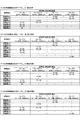
具体的に、図4に示すとおり、第1特別図柄表示器41aは、「i〜p」で示す8個のLEDで構成されており、第1特別図柄当否判定の結果に応じた第1特別図柄(第1識別情報)を表示する。例えば、第1特別図柄当否判定の結果が、第1大当り(15R大当り)となった場合には、「ijn」の3個のLEDを点灯し残りを消灯する(15R第1大当り図柄)。また、第2大当り(15R大当り)となった場合には、「ijk」の3個のLEDを点灯し残りを消灯する(15R第2大当り図柄)。また、第3大当り(2R大当り)となった場合には、「jnkl」の4個のLEDを点灯し残りを消灯する(2R第3大当り図柄)。また、小当りとなった場合には、「mnop」の4個のLEDを点灯し残りを消灯する(第1小当り図柄)。また、外れとなった場合には、「lo」の2個のLEDを点灯し残りを消灯する(外れ図柄)。一方、第2特別図柄表示器41bは、「a〜h」で示す8個のLEDで構成されており、第2特別図柄当否判定の結果に応じた第2特別図柄(第2識別情報)を表示する。例えば、第2特別図柄当否判定の結果が、第4大当り(15R大当り)となった場合には、「abd」の3個のLEDを点灯し残りを消灯する(15R第4大当り図柄)。また、第2小当りとなった場合には、「cdeh」の4個のLEDを点灯し残りを消灯する(第2小当り図柄)。また、外れとなった場合には、「eh」の2個のLEDを点灯し残りを消灯する(外れ図柄)。特別図柄が停止表示される前には所定の変動時間にわたって特別図柄の変動表示がなされるが、その変動表示の態様は、例えば予め定められた順序で、左から右へ光が繰り返し流れるように各LEDが点灯する態様とすることができる。
Specifically, as shown in FIG. 4, the first
本パチンコ遊技機1では、第1始動口20または第2始動口21への遊技球の入球があると、その入球に基づいて特別図柄当否判定用乱数等の各種情報(「取得情報」ともいう)を取得し、取得した各種情報は、主制御部のRAMに形成される特図保留記憶部(図示せず)に一旦記憶される。詳細には、第1始動口20への入球であれば第1特図保留(第1取得情報)として第1特図保留記憶部(図示せず)に記憶され、第2始動口21への入球であれば第2特図保留(第2取得情報)として第2特図保留記憶部(図示せず)に記憶される。各々の特図保留記憶部に記憶可能な特図保留(取得情報)の数は所定数までとされており、本実施例におけるその上限値はそれぞれ「4」となっている。これら第1特図保留記憶部および第2特図保留記憶部を、夫々「第1取得情報記憶手段」および「第2取得情報記憶手段」ともいい、総じて「取得情報記憶手段」ともいう。
In the
特図保留記憶部に記憶された特図保留は、その特図保留に基づく特別図柄の変動表示が可能となったときに消化される。特図保留の消化とは、その特図保留に対応する特別図柄当否判定用乱数等を判定して、その判定結果を示すための特別図柄の変動表示を実行することをいう。従って、本パチンコ遊技機1では、第1始動口20又は第2始動口21への遊技球の入球に基づく特別図柄の変動表示がその入球時にすぐに実行できない場合、すなわち特別図柄の変動表示の実行中や特別遊技の実行中である場合であっても、所定個数を上限として、その入球に対する特別図柄当否判定の権利を留保することが可能となっている。
The special figure hold stored in the special figure hold storage unit is digested when the variable display of the special symbol based on the special figure hold becomes possible. The digestion of the special symbol hold means to determine the random number for determining whether the special symbol is correct or not corresponding to the special symbol hold, and to execute the variable display of the special symbol to show the determination result. Therefore, in the
特図保留記憶部に記憶された特図保留の数は、第1特図保留表示器43aおよび第2特図保留表示器43bに表示される。具体的には、第1特図保留表示器43aは「uv」の2個のLEDで構成されており、第1特図保留の数に応じてLEDを表示制御することにより、第1特図保留の数を表示するものとなっている。例えば、保留数が「0」の場合は「u□v□」(例えば、□:消灯、●:赤点灯、▲:緑点灯とする)というように両LEDを消灯する表示態様とし、保留数が「1」の場合は「u□v●」というように「u」のLEDを消灯し「v」のLEDを赤色で点灯させる表示態様とし、保留数が「2」の場合は「u●v□」というように「u」のLEDを赤色で点灯させ「v」のLEDを消灯する表示態様とし、保留数が「3」の場合は「u●v●」というように両方のLEDを赤色で点灯させる表示態様とし、保留数が「4(上限数)」の場合は「u▲v▲」というように両方のLEDを緑色で点灯させ表示態様とすることができる。
The number of special figure hold stored in the special figure hold storage unit is displayed on the first special
また、第2特図保留表示器43bは「wx」の2個のLEDで構成されており、第2特図保留の数に応じてLEDを表示制御することにより、第2特図保留の数を表示するものである。例えば、保留数が「0」の場合は「w□x□」(例えば、□:消灯、●:赤点灯、▲:緑点灯とする)というように両LEDを消灯する表示態様とし、保留数「1」〜「4」についても第1特図保留表示器43aと同様に定められている。
Further, the second special
普通図柄の変動表示は、ゲート28への遊技球の通過を契機として行われる。普通図柄表示器42では、普通図柄を所定時間変動表示した後、停止表示し、停止表示された普通図柄(停止図柄)によって、ゲート28への遊技球の通過に基づく普通図柄当否判定の結果を報知する。停止表示される普通図柄は、普通図柄当否判定によって複数種類の普通図柄の中から選択された一つの普通図柄である。停止表示された普通図柄が予め定めた特定普通図柄(当り普通図柄)である場合には、現在の遊技状態に応じた開放パターンにて第2始動口21を開放させる補助遊技が行われる。尚、第2始動口21の開放パターンについては後述する。
The variable display of the normal symbol is performed when the game ball passes through the
具体的には図4に示す通り、普通図柄表示器42は、「st」の2個のLEDから構成されており、その点灯態様によって普通図柄当否判定の結果に応じた普通図柄を表示するものである。例えば、判定結果が当りである場合には、「s■t■」(例えば、■:点灯、□:消灯とする)というように両LEDが点灯した当り普通図柄を停止表示する。また判定結果が外れである場合には、「s□t■」というように「t」のLEDのみが点灯した態様の外れ普通図柄を表示する。尚、外れ普通図柄は、特定普通図柄ではない。普通図柄が停止表示される前には予め定められた所定の変動時間にわたって普通図柄の変動表示が実行されるが、その変動表示の態様は、例えば両LEDが交互に点灯・消滅を繰り返す態様である。
Specifically, as shown in FIG. 4, the
本パチンコ遊技機1では、ゲート28への遊技球の通過があると、その通過に基づいて普通図柄当否判定用乱数等の各種情報(「取得情報」ともいう)を取得し、取得した各種情報は主制御部のRAMに形成される普図保留記憶部(図示せず)に普図保留として一旦記憶される。普図保留記憶部に記憶可能な普図保留の数には上限が設定されており、本実施例における上限値は4個となっている。普図保留記憶部に記憶された普図保留は、その普図保留に基づく普通図柄の変動表示が可能となったときに消化される。普図保留の消化とは、その普図保留に対応する普通図柄当否判定用乱数を判定して、その判定結果を示すための普通図柄の変動表示を実行することをいう。従って本パチンコ遊技機1では、ゲート28への遊技球の通過に基づく普通図柄の変動表示がその通過時にすぐ実行できない場合、すなわち普通図柄の変動表示の実行中や補助遊技の実行中である場合であっても、所定個数を上限として、その通過に対する普通図柄当否判定の権利を留保することができるようになっている。
In the
普図保留記憶部に記憶された普図保留の数は、普図保留表示器44に表示される。具体的には普図保留表示器44は、「qr」の2個のLEDで構成されており、普図保留の数に応じてLEDを点灯させることにより普図保留の数を表示するものである。例えば、保留数が「0」の場合は「q□r□」(例えば、□:消灯、●:赤点灯、▲:緑点灯とする)というように両LEDを消灯する表示態様とし、保留数が「1」の場合は「q□r●」というように「q」のLEDを消灯し「r」のLEDを赤色で点灯させる表示態様とすることができる。また、保留数「2」〜「4」についても第1特図保留表示器43aと同様に定められている。
The number of the normal figure hold stored in the normal figure hold storage unit is displayed on the normal
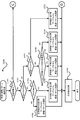
次に図2及び図5に基づいて、本パチンコ遊技機1における電気的な構成を説明する。本実施例のパチンコ遊技機1は、特別図柄当否判定や普通図柄当否判定や遊技状態の移行など、遊技進行や遊技利益に関する制御を行う主制御基板80(「主制御部」ともいい、「遊技制御部」ともいう)、遊技の進行に伴って実行する演出に関する制御を行うサブ制御基板90(「サブ制御部」ともいい、「演出制御部」ともいう)、遊技球の払い出しに関する制御を行う払出制御基板110(「払出制御部」ともいう)、画像表示装置7に表示される演出図柄8、演出表示器102に表示される図柄、演出第1特図保留表示器103a、及び演出第2特図保留表示器103b等の表示制御を行う画像制御基板100(画像制御部)等を備えている。
Next, the electrical configuration of the
また、図2に示すように、パチンコ遊技機1の後面側(裏面側)の略中央部には主制御基板80を収納した主制御基板収納ケースが設けられ、この主制御基板ケースの上方には、音声制御基板106、ランプ制御基板107及び画像制御基板100を収納した画像制御基板等収納ケースが設けられ、その画像制御基板等収納ケース上にはサブ制御基板90を収納したサブ制御基板収納ケースが設けられている。また、主制御基板ケースの下方左側には、払出制御基板を収納する払出制御基板ケースが設けられ、その右側には、電源基板109を収納する電源基板ケースが設けられている。
Further, as shown in FIG. 2, a main control board storage case for storing the
主制御基板80には、プログラムに従ってパチンコ遊技機1の遊技の進行を制御する遊技制御用ワンチップマイコン(以下「遊技制御用マイコン」)81が実装されている。遊技制御用マイコン81には、遊技の進行を制御するためのプログラム等を記憶したROM、ワークメモリとして使用されるRAM、ROMに記憶されたプログラムを実行するCPUが含まれている。遊技制御用マイコン81は、入出力回路87(I/Oポート部)を介して他の基板等とデータ(情報)の送受信を行う。入出力回路87は、遊技制御用マイコン81に内蔵されていてもよい。また、ROMは外付けであってもよい。遊技制御用マイコン81のRAMには、前述した特図保留記憶部(第1特図保留記憶部及び第2特図保留記憶部)と普図保留記憶部とが設けられている。
On the
主制御基板80には、中継基板88を介して各種センサやソレノイドが接続されている。そのため、主制御基板80には各センサから信号が入力され、各ソレノイドには主制御基板80から信号が出力される。具体的にはセンサ類としては、第1始動口センサ20a、第2始動口センサ21a、ゲートセンサ28a、第1大入賞口センサ30a、第2大入賞口センサ35a、特定領域センサ39aおよび一般入賞口センサ27aが接続されている。
Various sensors and solenoids are connected to the
第1始動口センサ20aは、第1始動口20内に設けられて第1始動口20に入球した遊技球を検知するものである。第2始動口センサ21aは、第2始動口21内に設けられて第2始動口21に入球した遊技球を検知するものである。ゲートセンサ28aは、ゲート28内に設けられてゲート28を通過した遊技球を検知するものである。第1大入賞口センサ30aは、第1大入賞口30内に設けられて第1大入賞口30に入球した遊技球を検知するものである。第2大入賞口センサ35aは、第2大入賞口35内に設けられて第2大入賞口35に入球した遊技球を検知するものである。特定領域センサ39aは、第2大入賞口35内の特定領域39に設けられており、特定領域39を通過した遊技球を検知するものである。一般入賞口センサ27aは、各一般入賞口27内にそれぞれ設けられて一般入賞口27に入球した遊技球を検知するものである。
The first
またソレノイド類としては、第2始動口ソレノイド24、第1大入賞口ソレノイド33、及び第2大入賞口ソレノイド38が接続されている。第2始動口ソレノイド24は、可変入賞装置22の可動部材23を駆動するためのものである。第1大入賞口ソレノイド33は、第1大入賞装置31の開閉部材32を駆動するためのものである。第2大入賞口ソレノイド38は、第2大入賞装置36の開閉部材37を駆動するためのものである。
Further, as the solenoids, the second
さらに主制御基板80には、第1特別図柄表示器41a、第2特別図柄表示器41b、普通図柄表示器42、第1特図保留表示器43a、第2特図保留表示器43b、普図保留表示器44、ラウンド表示器45、遊技状態表示器46、発射方向表示器47及び当り表示器48が接続されている。すなわち、これらの主表示器40の表示制御は、遊技制御用マイコン81によりなされる。
Further, the
また主制御基板80は、払出制御基板110に各種コマンドを送信するとともに、払い出し監視のために払出制御基板110から信号を受信する。払出制御基板110には、賞球や貸球を払い出す払出装置120、及びカードユニット135(パチンコ遊技機1に隣接して設置され、挿入されたプリペイドカード(遊技価値記憶媒体)等に記憶されている情報に基づいて球貸しを可能にするもの)が接続されているとともに、発射制御基板111(「発射制御部」ともいう)を介して発射装置112が接続されている。発射装置112には、発射ハンドル60(図1参照)が含まれる。
Further, the
払出制御基板110は、プログラムに従ってパチンコ遊技機1の遊技球の払い出しを制御する払出制御用ワンチップマイコン116(「払出制御用マイコン」ともいう)が実装されている。払出制御用マイコン116には、遊技球の払い出しを制御するためのプログラム等を記憶したROM、ワークメモリとして使用されるRAM、ROMに記憶されたプログラムを実行するCPUが含まれている。払出制御用マイコン116は、入出力回路117を介し、遊技制御用マイコン81からの信号や、パチンコ遊技機1に接続されたカードユニット135からの信号に基づいて、払出装置120の払出モータ121を駆動して賞球の払い出しを行ったり、貸球の払い出しを行ったりする。払い出される遊技球は、その計数のため払出センサ122、123により検知される。尚、遊技者による発射装置112のハンドル60(図1参照)の操作があった場合には、タッチスイッチ114が発射ハンドル60への遊技者の接触を検知し、発射ボリューム115が発射ハンドル60の回転量を検知する。そして、発射ボリューム115の検知信号の大きさに応じた強さで遊技球が発射されるよう発射モータ113が駆動制御されることとなる。
The
また主制御基板80は、サブ制御基板90に対し各種コマンドを送信する。主制御基板80とサブ制御基板90との接続は、主制御基板80からサブ制御基板90への信号の送信のみが可能な単方向通信接続となっている。すなわち、主制御基板80とサブ制御基板90との間には、通信方向規制手段としての図示しない単方向性回路(例えばダイオードを用いた回路)が介在している。
Further, the
また図5に示すように、サブ制御基板90には、プログラムに従ってパチンコ遊技機1の演出を制御する演出制御用ワンチップマイコン91(「演出制御用マイコン」)が実装されている。演出制御用マイコン91には、遊技の進行に伴って演出を制御するためのプログラム等を記憶したROM、ワークメモリとして使用されるRAM、ROMに記憶されたプログラムを実行するCPUが含まれている。演出制御用マイコン91は、入出力回路95を介して他の基板等とデータの送受信を行う。入出力回路95は、演出制御用マイコン91に内蔵されていてもよい。また、ROMは外付けであってもよい。また、サブ制御基板90(演出制御用マイコン91)のRAM(演出制御RAM)の所定アドレスには、各種フラグや各種計数カウンタに用いるための記憶領域が確保されている。
Further, as shown in FIG. 5, a one-
サブ制御基板90には、画像制御基板100、音声制御基板106、ランプ制御基板107が接続されている。サブ制御基板90の演出制御用マイコン91は、主制御基板80から受信したコマンドに基づいて、画像制御基板100の画像制御用ワンチップマイコン101(「画像制御用マイコン」)のCPUに、画像表示装置7、演出表示器102、演出第1特図保留表示器103a、及び演出第2保留表示器103bの表示制御を行わせる。画像制御基板100のRAMは、画像データを展開するためのメモリである。画像制御基板100のROMには、画像表示装置7に表示される静止画データや動画データ、具体的にはキャラクタ、アイテム、図形、文字、数字および記号等(演出図柄、保留図柄等を含む)や背景画像等の画像データが格納されている。画像制御用マイコン101は、演出制御用マイコン91からの指令に基づいてROMから画像データを読み出す。そして、読み出した画像データに基づいて表示制御を実行する。
An
演出表示器102は、2個のLEDからなり、演出図柄8の変動表示および停止表示にあわせて変動表示および停止表示を行い、2個のLEDの点灯・消灯または色の組合せにより、演出図柄8の表示結果(特別図柄当否判定の結果)を示す表示態様で停止表示する。また、演出第1特図保留表示器103aおよび演出第2保留表示器103bも同様に2個のLEDからなる。そして、2個のLEDの点灯・消灯または色の組合せにより、演出第1特図保留表示器103aは第1演出保留表示領域9cに表示される保留個数および第1特図保留表示器43aで表示される保留個数と同じ保留個数を示す表示態様で表示制御される。また、演出第2特図保留表示器103bは第2演出保留表示領域9dに表示される保留個数および第2特図保留表示器43bで表示される保留個数と同じ保留個数を示す表示態様で表示制御される。これは、キャラクタ図柄を表示画面7a(演出図柄表示部)の略全体に表示したり、第1演出可動部材14Aや第2演出可動部材14Bを動作させて表示画面7aの演出図柄表示領域7b(演出図柄表示部)を被覆したりすることで、演出図柄、第1演出保留表示部や第2演出保留表示部の一部または全部が視認できない状態になることがあり得るため、この様な表示器が設けられている。尚、画像制御基板100の画像制御用ワンチップマイコン101に換えて、または加えてVDP(Video Display Processor)を設けてもよい。
The
また演出制御用マイコン91は、主制御基板80から受信したコマンドに基づいて、音声制御基板106を介してスピーカ67から音声、楽曲、効果音等を出力する。スピーカ67から出力する音声等の音響データは、サブ制御基板90のROMに格納されている。尚、音声制御基板106にCPUを実装してもよく、その場合、そのCPUに音声制御を実行させてもよい。さらにこの場合、音声制御基板106にROMを実装してもよく、そのROMに音響データを格納してもよい。また、スピーカ67を画像制御基板100に接続し、画像制御用マイコン101に音声制御を実行させてもよい。さらにこの場合、画像制御基板100のROMに音響データを格納してもよい。
Further, the
また演出制御用マイコン91は、主制御基板80から受信したコマンドに基づいて、枠ランプ66や盤面ランプ5等のランプの発光態様を決める発光パターンデータ(点灯/消灯や発光色等を決めるデータ、ランプデータともいう)を、ROMに格納されているデータから決定し、ランプ制御基板107を介して枠ランプ66や盤面ランプ5等のランプ(LED)の点灯制御を行う。
Further, the
さらに演出制御用マイコン91は、主制御基板80から受信したコマンドに基づいて、ランプ制御基板107に中継基板108を介して接続された第1〜第3演出駆動源14a,14b,14c(図5参照)を駆動して、第1演出可動部材14Aや第2演出可動部材14B、第2演出ボタン63bを動作させる。前述したように、第1演出可動部材14Aおよび第2演出可動部材14Bは、センター装飾体10に設けられた可動式のいわゆるギミックのことである。また、第2演出ボタン63bもギミックとして機能するもので、前面枠51の手前側に突出可能に設けられている。以下では、これら第1演出可動部材14A、第2演出可動部材14Bおよび第2演出ボタン63bのことを「演出可動部材」ともいう。尚、第1演出可動部材14A、第2演出可動部材14Bおよび第2演出ボタン63b(演出可動部材)は、本発明の「可動演出手段」の一態様を示すものである。
Further, the
演出制御用マイコン91は、第1演出可動部材14A、第2演出可動部材14Bおよび第2演出ボタン63bを、所定の動作態様で動作させるための動作パターンデータ(「駆動データ」ともいう)を、サブ制御基板90のROMに格納されているデータから決定し、決定した動作パターンデータに基づいて第1〜第3演出駆動源14a,14b,14c(本実施例ではステッピングモータ)を駆動して、第1演出可動部材14A、第2演出可動部材14Bおよび第2演出ボタン63bの動作を制御する。尚、ランプ制御基板107にCPUを実装してもよく、その場合、そのCPUにランプの点灯制御や、第1演出可動部材14A、第2演出可動部材14Bおよび第2演出ボタン63bの動作制御を実行させてもよい。さらにこの場合、ランプ制御基板107にROMを実装してもよく、そのROMに発光パターンや動作パターンに関するデータを格納してもよい。また、第1演出可動部材14Aは複数の装飾LEDを含んで構成されており、装飾LEDの発光態様(点灯/消灯/点滅や発光色等)を決める発光パターンデータも、第1演出可動部材14Aの動作パターンデータに含まれている。このため、第1演出可動部材14Aの動作には、上下動だけでなく装飾LEDの発光(点灯/点滅等)も含まれることとなる。
The
また、サブ制御基板90には、第1演出ボタン63aが操作されたことを検知する第1演出ボタン検知スイッチ63cと、第2演出ボタン63bが操作されたことを検知する第2演出ボタン検知スイッチ63dが接続されている。従って、第1演出ボタン63aまたは第2演出ボタン63bに対して遊技者が所定の入力操作を行うと、対応する演出ボタン検知スイッチからサブ制御基板90に対して信号が出力される。尚、第1演出ボタン検知スイッチ63cおよび第2演出ボタン検知スイッチ63dを総称して単に「演出ボタン検知スイッチ」ともいう。
Further, on the
また、サブ制御基板90には、可動演出設定スイッチ82が接続されている。この可動演出設定スイッチ82は、ギミックとして機能する第1演出可動部材14A、第2演出可動部材14Bおよび第2演出ボタン63bについて、その動作を有効(ON)とするか無効(OFF)とするかを設定する(切り替える)ためのものである。本実施例では、図2および図48に示すように、可動演出設定スイッチ82を、パチンコ遊技機1の裏面側から操作可能であってサブ制御基板90に実装されたディップスイッチによって構成している。そして、演出制御用マイコン91は、可動演出設定スイッチ82の設定状況に基づいて、第1演出可動部材14Aや第2演出可動部材14B、第2演出ボタン63bの動作を含む演出(以下、「可動演出」ともいう)に係る制御を行うものとなっている。すなわち、可動演出設定スイッチ82のうち、ONとなっている設定スイッチに対応する可動演出部材(本例では演出ボタンを含む)の動作を含む演出については実行可能とし、OFFとなっている設定スイッチに対応する可動演出部材(本例では演出ボタンを含む)の動作を含む演出については実行不能として、演出制御を行う。尚、可動演出設定スイッチ82は、本発明の「入力手段」の一態様を示すものである。
Further, a movable
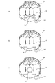
本実施例の可動演出設定スイッチ82は、図48に示すように、第1演出可動部材14A、第2演出可動部材14Bおよび第2演出ボタン63bの各々について、動作のON/OFFを設定するための3つの設定スイッチを備えている。具体的には、第1演出可動部材14AのON/OFFを設定する第1設定スイッチ82aと、第2演出可動部材14BのON/OFFを設定する第2設定スイッチ82bと、第2演出ボタン63bのON/OFFを設定する第3設定スイッチ82cと、を備えている。通常は、図48(a)に示すように、3つの設定スイッチ82a,82b,82cがすべてONの位置となっており、これが基本の設定状態(デフォルト)となる。この基本の設定状態(初期設定)では、第1演出可動部材14Aの動作を含む演出、第2演出可動部材14Bの動作を含む演出および第2演出ボタン63bの動作を含む演出の何れについても、遊技進行過程で出現し得るものとなる。つまり、第1演出可動部材14A、第2演出可動部材14Bおよび第2演出ボタン63bの何れもが、遊技中に動作し得るものとなる。
As shown in FIG. 48, the movable
これに対し、例えば、図48(b)に示すように、3つの設定スイッチのうち第1設定スイッチ82aを操作してOFFにして、残りの設定スイッチ82b,82cをONにすると、第1演出可動部材14Aの動作を含む演出が出現しなくなり、第2演出可動部材14Bの動作を含む演出および第2演出ボタン63bの動作を含む演出が出現し得るものとなる。つまり、第1演出可動部材14Aは遊技中に動作せず、第2演出可動部材14Bおよび第2演出ボタン63bが遊技中に動作し得るものとなる。同様に、図48(c)に示すように第2設定スイッチ82bをOFFにすると、第2演出可動部材14Bの動作を含む演出が出現しなくなって、第2演出可動部材14Bは動作しないものとなり、図48(d)に示すように第3設定スイッチ82cを操作してOFFにすると、第2演出ボタン63bの動作を含む演出が遊技進行過程で出現しなくなって、第2演出ボタン63bは動作しないものとなる。尚、図48では、説明の便宜上、3つの設定スイッチ82a,82b,82cのうち夫々1つをOFFにする例を示しているが、この他にも、3つの設定スイッチ82a,82b,82cのうち2つをOFFにしたり、3つの設定スイッチ82a,82b,82cのすべてをOFFにしたりすることもあり得る。
On the other hand, for example, as shown in FIG. 48 (b), when the
このように、可動演出設定スイッチ82によって、第1演出可動部材14A、第2演出可動部材14Bおよび第2演出ボタン63bの各々について動作のON/OFFを設定可能(切替可能)としているのは、次の理由による。すなわち、第1演出可動部材14A、第2演出可動部材14Bおよび第2演出ボタン63bの何れかについて、駆動機構を含めて動作不良や故障等の何らかの不具合が生じたり、その不具合の兆候が表れたりした場合、その不具合の見られる演出可動部材に対応する設定スイッチをOFFにして、以後、その演出可動部材に係る可動演出が出現しないようにして、不具合の見られる演出可動部材を動作させないようにするためである。このような可動演出のON/OFF設定に係る演出制御についての詳細は後述する。
In this way, the movable
次に、本実施例のパチンコ遊技機1における当否判定に係る制御について説明する。特別図柄当否判定の結果として、「大当り」、「小当り」、「外れ」がある。「大当り」のときには、特別図柄表示部41に「大当り図柄」が停止表示される。また「小当り」のときには、特別図柄表示部41に「小当り図柄」が停止表示される。また「外れ」のときには、特別図柄表示部41に「外れ図柄」が停止表示される。大当り又は小当りと判定されると、停止表示された特別図柄の種類に応じた開放パターンにて、第1大入賞口30又は第2大入賞口35を開放する「特別遊技」が実行される。大当りとなって実行される特別遊技を「大当り遊技」と言い、小当りとなって実行される特別遊技を「小当り遊技」と言う。
Next, the control related to the hit / fail determination in the
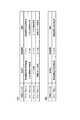
当りには複数の種別がある。図6に示すように当りの種別としては、「15R(ラウンド)第1大当り」、「15R第2大当り」、「2R第3大当り」および「15R第4大当り」がある。「15R第1大当り」および「15R第4大当り」は、大入賞口(第1大入賞口30又は第2大入賞口35)の開放回数(ラウンド数)が15回であり、1ラウンド目と2ラウンド目に、特定領域39への遊技球の通過が可能(容易)な態様で第2大入賞口35を開放させる大当りである。この特定領域39への遊技球の通過を狙うラウンドを、チャンスラウンドやチャレンジラウンドということができる。「15R第2大当り」は、大入賞口(第1大入賞口30又は第2大入賞口35)の開放回数(ラウンド数)が15回であるものの、前述のチャンスラウンドである1ラウンド目と2ラウンド目の開放時間が極短時間(一瞬開閉)で、特定領域39への遊技球の通過が困難(不可能としてもよい)な大当りである。すなわち、この「15R第2大当り」は、特定領域39への遊技球の通過が可能(容易)な態様で第2大入賞口35を開放させることのない大当りであるといえる。「2R第3大当り」は、大入賞口(第1大入賞口30又は第2大入賞口35)の開放回数(ラウンド数)が2回であり、チャンスラウンドである1ラウンド目と2ラウンド目に特定領域39への遊技球の通過が可能な態様で第2大入賞口35を開放させる大当りである。但し、第2大入賞口35の開放時間が1ラウンド目と2ラウンド目を合わせても1.8秒であるので、15R第1大当りより特定領域への遊技球の通過可能性が低いものとなっている。
There are multiple types of hits. As shown in FIG. 6, the types of hits include "15R (round) first big hit", "15R second big hit", "2R third big hit" and "15R fourth big hit". In "15R 1st jackpot" and "15R 4th jackpot", the number of times (the number of rounds) of opening the big winning opening (1st big winning
本実施例のパチンコ遊技機1では、大当り遊技中の特定領域39への遊技球の通過に基づいて、その大当り遊技の終了後の遊技状態を、後述の高確率状態に移行させる。従って、特別図柄当否判定の結果が前述の15R第1大当りまたは15R第4大当りとなった場合には、特定領域39への遊技球の通過可能性が極めて高い態様で1ラウンド目と2ラウンド目のチャンスラウンドが実行されるため、当該大当り遊技の実行中に特定領域39へ遊技球を通過させることで、大当り遊技後の遊技状態を高確率状態に移行させることができる。つまり、15R第1大当りおよび15R第4大当りは、実質的に「確変大当り」といえる。
In the
また、特別図柄当否判定の結果が2R第3大当りとなった場合には、15R第1大当りや15R第4大当りほどではないものの特定領域39への遊技球の通過可能性がある態様で1ラウンド目と2ラウンド目のチャンスラウンドが実行されるため、当該大当り遊技の実行中に特定領域39へ遊技球を通過させることができれば、大当り遊技後の遊技状態を高確率状態に移行させることができる。これに対して、15R第2大当りとなった場合には、1ラウンド目と2ラウンド目のチャンスラウンドの開放時間が各0.1秒であるので、第2大入賞口へ遊技球を入球させるのが非常に困難であるので、当該大当り遊技の実行中に特定領域39へ遊技球を通過させることができず、その大当り遊技後の遊技状態は、後述の通常状態(低確率状態)となる可能性が非常に高い(低確率状態になるといってもよい)。つまり、15R第2大当りは、実質的に「通常大当り(時短大当り)」といえる。
In addition, when the result of the special symbol hit / fail judgment is the 2R 3rd big hit, one round in such a manner that the game ball may pass through the
一方、小当りは、見かけ上2R第3大当りと同じ開放パターンで大入賞口(第2大入賞口35)を開放させる当りである。すなわち小当りでは、特定領域39への遊技球の通過が可能な態様で第2大入賞口35を開放させる。しかしながら、小当り遊技の実行中に特定領域39への遊技球の通過があっても、小当り遊技の実行後の遊技状態は小当り遊技の実行前と変化しないもの(同様)となっている。このため、小当り遊技の実行前の遊技状態が通常状態(低確率状態)であれば、小当り遊技の実行後(終了後)の遊技状態も通常状態となる。そして遊技者から見れば、上記の2R第3大当りと小当りとは大入賞口(第2大入賞口35)の開放パターンを見ても区別することができない。すなわち遊技者は特別図柄当否判定の結果が「2R第3大当り」になったのか「小当り」になったのかを認識するのが困難である。そのため、2R第3大当りとしての特別遊技中(大当り遊技中)に遊技球が特定領域39を通過したとしても、それだけでは、その後の遊技状態が高確率状態に移行したかどうかを認識するのは困難である。また、小当りとしての特別遊技中(小当り遊技中)に遊技球が特定領域39を通過したとしても、それだけでは、その後の遊技状態が通常状態のままか、高確率状態に移行したかを認識するのは困難である。その結果、小当りや2R第3大当りになった場合には、高確率状態であるかもしれないという期待感を持ちつつ遊技を進行することができ、遊技興趣を高めることができる。尚、小当りにおいては大入賞口の開放回数を、ラウンド数とは言わず、単に開放回数という。
On the other hand, the small hit is a hit that opens the big winning opening (the second big winning opening 35) in the same opening pattern as the 2R third big hit. That is, in the small hit, the second large winning
本実施例のパチンコ遊技機1における各大当り及び小当りとなったときの大入賞口の開放パターンは、図6のようになっている。すなわち、15R第1大当りとなった場合(第1特別図柄表示器41aに15R第1大当り図柄が停止表示された場合)、及び15R第4大当りとなった場合(第2特別図柄表示器41bに15R第4大当り図柄が停止表示された場合)には、1R〜2Rまでは第2大入賞口35を最大28秒開放し、3R〜15Rまでは第1大入賞口30を最大28秒開放させる。この当りでは、1R目および2R目における第2大入賞口35の開放時間が夫々28秒あるため、そのラウンド中に遊技球が特定領域39を通過する可能性は極めて高いものとなっている。
The opening pattern of the big winning opening when each big hit and small hit in the
また、15R第2大当りとなった場合(第1特別図柄表示器41aに15R第2大当り図柄が停止表示された場合)には、1R〜2Rまでは第2大入賞口35を最大0.1秒開放し、3R〜15Rまでは第1大入賞口30を最大28秒開放させる。この当りでは、1R目及び2R目における第2大入賞口35の開放時間が夫々最大0.1秒と極短時間とされている(一瞬開閉)ため、そのラウンド中に遊技球が特定領域39を通過することは、ほぼ不可能となっている。すなわち、15R第2大当り用の開放パターンは、15R第1大当り用の開放パターンと比べて第1ラウンドおよび第2ラウンドの開放態様が異なる。つまり、15R第1大当りでは、1ラウンド目および2ラウンド目に第2大入賞口35が28秒開放するため、第2大入賞口35に遊技球が容易に入球する。そして、第2大入賞口35に入球した遊技球は、高い可能性で特定領域39を通過する。これに対して、15R第2大当りでは、1ラウンド目および2ラウンド目に第2大入賞口35が0.1秒しか開放しない。そのため、第2大入賞口35に遊技球が入球することは非常に困難である。従って、15R第2大当りに係る大当り遊技の実行中に遊技球が特定領域39を通過する可能性は、15R第1大当りと比してかなり低くなっており、実質的には通過不可能といってもよい。
In addition, when the 15R second big hit is reached (when the 15R second big hit symbol is stopped and displayed on the first
また図6に示すように、2R第3大当りに当選した場合(第1特別図柄表示器41aに2R第3大当り図柄が停止表示された場合)には、1R〜2Rまで第2大入賞口35を最大0.9秒開放させる。この当りでは、1R目および2R目における第2大入賞口35の開放時間が合計1.8秒あるため、そのラウンド中に遊技球を第2大入賞口35に入球させて特定領域39を通過させることが可能となっている。本パチンコ遊技機1においては、0.6秒程度で一発の遊技球が発射されるようになっているので、第2大入賞口35の開放時間が1.8秒あれば、第2大入賞口35へ遊技球を入球させて特定領域39への遊技球の通過を狙うことは十分に可能である。但し、2R第3大当りは、第2大入賞口35の総開放時間が1.8秒と短いため、他の15R大当りのように多くの賞球(遊技利益)を望めるものではない。すなわち他の大当りに比してほとんど賞球の獲得できない大当りである。
Further, as shown in FIG. 6, when the 2R 3rd jackpot is won (when the 2R 3rd jackpot symbol is stopped and displayed on the 1st
また、第1小当りとなった場合(第1特別図柄表示器41aに第1小当り図柄が停止表示された場合)と、第2小当りとなった場合(第2特別図柄表示器41bに第2小当り図柄が停止表示された場合)には、第2大入賞口35の最大0.9秒間の開放を2回行う。すなわち、2R第3大当りと同じ開放パターンにて大入賞口を開放させる。この小当りにおいても、第2大入賞口35の開放時間が合計1.8秒あるため、遊技球を第2大入賞口35に入球させて特定領域39を通過させることが可能となっている。しかし前述の通り、特定領域39への通過があっても小当り遊技の前後で遊技状態の変化はない。またこの小当りは、大入賞口の総開放時間が1.8秒と短いため、2R第3大当りと同様に多くの賞球を望めるものではない。すなわち小当りは、遊技状態の移行という点についても、賞球という点についても、遊技者にとっての特典がほぼないもの(入球による賞球のみ)となっている。すなわち、本実施例では、第2大入賞口35の開放パターンとして、遊技球が特定領域39を通過可能(通過容易)な第1の開放パターンと(15第1大当り、15R第4大当り)、遊技球が特定領域39を通過困難(通過不能)な第2の開放パターンと(15R第2大当り)、遊技球が特定領域を通過可能であって第1の開放パターンより通過可能性が低い第3の開放パターンと(2R第3大当り)、を有するものとなっている。また、小当り用の開放パターンとして、遊技球が特定領域39を通過可能であるが通過した場合であっても特典を付与しない(高確率状態を発生しない)第4の開放パターンを有するものとなっている。尚、第4の開放パターンについては、他の態様として特定領域39を通過不能な開放パターンとしてもよい。
In addition, when it becomes the first small hit (when the first small hit symbol is stopped and displayed on the first
また、本実施例において、第1特別図柄(特図1)の当否判定における各大当りへの振分確率は、15R第1大当りが40%、15R第2大当りが50%、2R第3大当りが10%となっている(図6の大当り種別決定用乱数の欄を参照)。これに対して、第2特別図柄(特図2)の当否判定における大当りは、全て15R第4大当りとなっている(図6の大当り種別決定用乱数の欄を参照)。すなわち、後述の開放延長機能の作動(高ベース状態の発生)により入球容易となった第2始動口21への入球に基づく当否判定により大当りとなった場合には、必ず15R第4大当りとなる。このように本パチンコ遊技機1では、第1始動口20に遊技球が入球して行われる当否判定(第1特別図柄の大当り抽選)において大当りとなるよりも、第2始動口21に遊技球が入球して行われる当否判定(第2特別図柄の大当り抽選)において大当りとなる方が、遊技者にとって有利となる可能性が高くなるように設定されている。すなわち、遊技者は、第2始動口21への入球を期待して遊技を行う。特に第2始動口21への入球頻度が高まる開放延長機能の作動中においては顕著である。
Further, in this embodiment, the distribution probability to each jackpot in the hit / fail judgment of the first special symbol (special figure 1) is 40% for the 15R first jackpot, 50% for the 15R second jackpot, and 2R third jackpot. It is 10% (see the column of random numbers for determining the jackpot type in FIG. 6). On the other hand, the jackpots in the hit / fail judgment of the second special symbol (special figure 2) are all 15R fourth jackpots (see the column of random numbers for determining the jackpot type in FIG. 6). That is, when a big hit is made based on the hit / fail judgment based on the entry into the
ここで本パチンコ遊技機1では、大当りか、小当りか、外れかの判定は「特別図柄当否判定用乱数(「当否判定用情報」ともいう)」に基づいて行われ、大当りとなった場合の大当りの種別の判定は「大当り種別決定用乱数(「図柄決定用乱数」、「図柄決定用情報」ともいう)」に基づいて行われる。図7(A)に示すように、特別図柄当否判定用乱数は「0〜629」の範囲で値をとり、大当り種別決定用乱数は「0〜99」の範囲で値をとる。尚、第1始動口20または第2始動口21への入球に基づいて取得される乱数(取得情報)には、特別図柄当否判定用乱数および大当り種別決定用乱数の他に、「リーチ乱数(「リーチ情報」ともいう)」および「変動パターン乱数(「変動パターン情報」ともいう)」がある。
Here, in this
リーチ乱数は、特別図柄当否判定の結果が外れである場合に、演出図柄を用いてその結果を示す遊技演出(演出図柄遊技演出)においてリーチを発生させるか否かを決める乱数である。リーチとは例えば、左と右の2個の演出図柄8R、8Lが同じ図柄で停止(仮停止)され、残り1個の中演出図柄8Cが変動中の状態をいう(「7↓7」の状態)。そして、変動中の中演出図柄8Cが停止中の演出図柄8R、8Lと同じ図柄で停止すれば、3つの演出図柄が同一の図柄で停止することとなり、当りとなる。尚、この場合の演出図柄の停止(仮停止)には、演出図柄表示領域7b内で多少揺れているような表示(揺れ変動)も含まれる。このリーチ乱数は「0〜126」の範囲で値をとる。また、変動パターン乱数は、変動時間を含む変動パターンを決めるための乱数で、「0〜198」の範囲で値をとる。
The reach random number is a random number that determines whether or not to generate a reach in a game effect (effect symbol game effect) that indicates the result by using the effect symbol when the result of the special symbol hit / fail determination is incorrect. Reach means, for example, a state in which two left and
また、ゲート28の通過に基づいて取得される乱数には、図7(B)に示す普通図柄当否判定用乱数がある。普通図柄当否判定用乱数は、第2始動口21を開放させる補助遊技を行うか否かの判定(普通図柄抽選)のための乱数である。普通図柄乱数は、0〜240までの範囲で値をとる。
Further, the random numbers acquired based on the passage of the
次に、本実施例のパチンコ遊技機1の遊技状態について説明する。パチンコ遊技機1は、特別図柄に対する確率変動機能および変動時間短縮機能、普通図柄に対する確率変動機能および変動時間短縮機能、第2始動口21(可変入賞装置22)の開放延長機能の各機能が作動状態または非作動状態となる組合せにより、複数の遊技状態を有している。特別図柄(第1特別図柄および第2特別図柄)について確率変動機能が作動している状態を「高確率状態」といい、作動していない状態を「通常状態(「低確率状態」ともいう)」という。高確率状態では、特別図柄当否判定において大当りと判定される確率(大当り確率)が通常状態よりも高くなっている。すなわち、通常状態では通常状態用の大当り判定テーブルを用いて当否判定を行うものの、高確率状態では、大当りと判定される特別図柄当否判定用乱数の値が多い高確率状態用の大当り判定テーブルを用いて、当否判定を行う(図8(A)参照)。つまり、特別図柄の確率変動機能が作動すると、作動していないときに比して、特別図柄の変動表示の結果が大当りとなる(停止図柄が大当り図柄となる)確率が高くなる。
Next, the gaming state of the
また、特別図柄(第1特別図柄および第2特別図柄)について変動時間短縮機能が作動している状態を「時短状態」といい、作動していない状態を「非時短状態」という。時短状態では、特別図柄の変動時間(変動表示の開始時から確定表示時までの時間)の平均値が、非時短状態における特別図柄の変動時間の平均値よりも短くなっている。すなわち、時短状態においては、変動時間の短い変動パターンが選択されることが非時短状態よりも多くなるように定められた変動パターンテーブルを用いて、変動パターンの判定を行う(図9参照)。その結果、時短状態では、特図保留の消化のペースが速くなり、始動口への有効な入球(特図保留として記憶され得る入球)が発生しやすくなる。そのため、スムーズな遊技の進行のもとで大当りを狙うことができる。 Further, for the special symbols (first special symbol and second special symbol), the state in which the fluctuation time shortening function is operating is referred to as a "time saving state", and the state in which the special symbol is not operating is referred to as a "non-time saving state". In the time saving state, the average value of the fluctuation time of the special symbol (the time from the start of the fluctuation display to the confirmation display time) is shorter than the average value of the fluctuation time of the special symbol in the non-time saving state. That is, in the time saving state, the fluctuation pattern is determined using the fluctuation pattern table defined so that the fluctuation pattern having the short fluctuation time is selected more often than in the non-time saving state (see FIG. 9). As a result, in the time-saving state, the pace of digestion of the special figure hold becomes faster, and effective ball entry to the starting port (ball entry that can be stored as special figure hold) is likely to occur. Therefore, it is possible to aim for a big hit under the smooth progress of the game.
特別図柄(第1特別図柄および第2特別図柄)についての確率変動機能と変動時間短縮機能とは同時に作動することもあるし、片方のみが作動することもある。そして、普通図柄についての確率変動機能および変動時間短縮機能は、特別図柄の変動時間短縮機能に同期して作動するようになっている。すなわち、普通図柄の確率変動機能および変動時間短縮機能は、特別図柄の時短状態において作動し、非時短状態において作動しない。よって、時短状態では、普通図柄当否判定における当り確率が非時短状態よりも高くなっている。すなわち、当りと判定される普通図柄乱数(当り乱数)の値が非時短状態で用いる普通図柄当り判定テーブルよりも多い普通図柄当り判定テーブルを用いて、普通図柄当否判定(普通図柄の判定)を行う(図8(D)参照)。つまり、普通図柄表示器42の確率変動機能が作動すると、作動していないときに比して、普通図柄の変動表示の結果が当りとなる(停止図柄が普通当り図柄となる)確率が高くなる。
The probability fluctuation function and the fluctuation time shortening function for the special symbols (first special symbol and second special symbol) may be operated at the same time, or only one of them may be operated. Then, the probability fluctuation function and the fluctuation time shortening function for the normal symbol operate in synchronization with the fluctuation time shortening function for the special symbol. That is, the probability fluctuation function and the fluctuation time shortening function of the normal symbol operate in the time saving state of the special symbol, and do not operate in the non-time saving state. Therefore, in the time-saving state, the hit probability in the normal symbol winning / failing determination is higher than in the non-time-saving state. That is, the normal symbol hit / fail judgment (judgment of the normal symbol) is performed using the normal symbol hit judgment table in which the value of the normal symbol random number (hit random number) judged to be a hit is larger than the normal symbol hit judgment table used in the non-time saving state. (See FIG. 8 (D)). That is, when the probability fluctuation function of the
また時短状態では、普通図柄の変動時間が非時短状態よりも短くなっている。本実施例では、普通図柄の変動時間は非時短状態では30秒であるが、時短状態では1秒である(図8(E)参照)。さらに時短状態では、補助遊技における第2始動口21の開放時間が、非時短状態よりも長くなっている。すなわち、可変入賞装置22の開放時間延長機能が作動している。加えて時短状態では、補助遊技における第2始動口21の開放回数が非時短状態よりも多くなっている。すなわち、可変入賞装置22の開放回数増加機能が作動している。具体的に、非時短状態において普通図柄当否判定の結果が当りになると、可変入賞装置22の開閉部材37が0.2秒の開放動作を1回行い、その期間第2始動口が開状態となる。また時短状態において普通図柄当否判定の結果が当りになると、可変入賞装置22の開閉部材37が2.0秒の開放動作を3回行うものとされる。
Also, in the time-saving state, the fluctuation time of the normal symbol is shorter than in the non-time-saving state. In this embodiment, the fluctuation time of the normal symbol is 30 seconds in the non-time saving state, but is 1 second in the time saving state (see FIG. 8 (E)). Further, in the time saving state, the opening time of the
普通図柄についての確率変動機能および変動時間短縮機能、並びに、可変入賞装置22の開放時間延長機能および開放回数増加機能が作動している状況下では、これらの機能が作動していない場合に比して、第2始動口21が頻繁に開放され、第2始動口21へ遊技球の入球頻度が高くなる(「高頻度状態」ともいう)。その結果、発射球数に対する賞球数の割合であるベースが高くなる。従って、これらの機能が作動している状態を「高ベース状態」といい、作動していない状態を「低ベース状態」という。高ベース状態(高頻度状態)では、手持ちの遊技球を大きく減らすことなく大当りを狙うことができる。
In the situation where the probability fluctuation function and the fluctuation time shortening function for the normal symbol, and the opening time extending function and the opening number increasing function of the variable winning
高ベース状態(高頻度状態)は、上記の全ての機能が作動するものでなくてもよい。すなわち、普通図柄についての確率変動機能および変動時間短縮機能、並びに、可変入賞装置22の開放時間延長機能および開放回数増加機能のうち少なくとも一つの機能の作動によって、その機能が作動していないときよりも第2始動口21が開放され易く(入球頻度が高く)なっていればよい。また、高ベース状態は、特別図柄の時短状態に付随せずに独立して制御されるようにしてもよい。この様な高ベース状態を発生する機能を「高ベース発生機能」ということもできる。
The high base state (high frequency state) does not have to activate all the above functions. That is, by operating at least one of the probability fluctuation function and the fluctuation time shortening function for the normal symbol, and the opening time extending function and the opening number increasing function of the variable winning
本実施例のパチンコ遊技機1では、15R第1大当りとなった場合の大当り遊技終了後の遊技状態は、その大当り遊技中に遊技球が特定領域39を通過していれば、特別図柄の高確率状態かつ特別図柄の時短状態かつ高ベース状態となる(図6参照)。この遊技状態を特に「高確高ベース状態」という。高確高ベース状態は、所定回数(本例では100回の特別図柄の変動表示が実行されるか、大当りとなって大当り遊技が実行されることにより終了する。
In the
また、15R第2大当りとなった場合の大当り遊技終了後の遊技状態は、その大当り遊技中に遊技球が特定領域39を通過することは極めて困難であるので、特別図柄の通常状態かつ特別図柄の時短状態かつ高ベース状態となる(図6参照)。この遊技状態を特に、「低確高ベース状態」という。低確高ベース状態は、所定回数(例えば100回)の特別図柄の変動表示が実行されるか、大当りに当選してその大当り遊技が実行されることにより終了する。尚、可能性は限りなく低いが、仮に、15R第2大当りに係る大当り遊技中に遊技球が特定領域39を通過した場合には、その大当り遊技終了後の遊技状態は「高確高ベース状態」となる。また、可能性は限りなく低いが、仮に、15R第1大当りに係る大当り遊技中に遊技球が特定領域39を通過しなかった場合には、その大当り遊技終了後の遊技状態は「低確高ベース状態」となる。
Further, in the gaming state after the jackpot game is completed when the 15R second jackpot is reached, it is extremely difficult for the game ball to pass through the
また、特別図柄の通常状態かつ特別図柄の非時短状態かつ低ベース状態である「低確低ベース状態」において、2R第3大当りとなった場合の大当り遊技終了後の遊技状態は、その大当り遊技中に遊技球が特定領域39を通過していれば、特別図柄の高確率状態かつ特別図柄の非時短状態かつ低ベース状態となる(図6参照)。この遊技状態を特に「高確低ベース状態」という。高確低ベース状態は、所定回数(本例では100回)の特別図柄の変動表示が実行されるか、大当りとなって大当り遊技が実行されることにより終了する。
In addition, in the "low probability low base state" in which the special symbol is in the normal state and the special symbol is in the non-time saving state and the low base state, the gaming state after the jackpot game ends when the 2R third jackpot is reached is the jackpot game. If the game ball passes through the
この高確低ベース状態は、高確率状態であることが潜伏している状態、すなわち高確率状態であることが遊技者にとって認識困難な状態である。つまり高確低ベース状態は、いわゆる「潜伏確変状態(「確率非報知状態」ともいう)」である。これに対して、上記の高確高ベース状態は、高確率状態であることが遊技者にとって明らかな状態である。つまり高確高ベース状態は、いわゆる「確変遊技状態」である。 This high-probability low-base state is a state in which the high-probability state is latent, that is, the high-probability state is difficult for the player to recognize. That is, the high probability low base state is a so-called "latent probability change state (also referred to as" probability non-notification state ")". On the other hand, the above-mentioned high-probability high-base state is a state in which it is clear to the player that it is a high-probability state. That is, the high-accuracy high-base state is the so-called "probability-changing game state".
また、高ベース状態において、2R第3大当りとなった場合の大当り遊技終了後の遊技状態は、その大当り遊技中に遊技球が特定領域39を通過していれば「高確高ベース状態」となる(図6参照)。すなわち、特別図柄の時短機能およびベース状態については、大当り遊技の実行前の状態と同じ状態とされる。
Further, in the high base state, the game state after the end of the big hit game when the 2R third big hit is reached is "high accuracy high base state" if the game ball passes through the
高確高ベース状態や低確高ベース状態といった高ベース状態では、右打ちにより右遊技領域3Bへ遊技球を進入させた方が有利に遊技を進行できる。高ベース状態では、低ベース状態と比べて第2始動口21が開放されやすくなっており、第1始動口20への入球よりも第2始動口21への入球の方が容易となっているからである。そのため、高ベース状態では、普通図柄当否判定の契機となるゲート28へ遊技球を通過させつつ、第2始動口21へ遊技球を入球させるべく右打ちを行うことで、左打ちを行うよりも、多数の始動入球(特別図柄当否判定の機会)を得ることができる。この状態のとき、発射方向表示器47が所定の態様で点灯制御され、右遊技領域へ発射すべきことを報知する。
In a high base state such as a high accuracy high base state or a low accuracy high base state, it is more advantageous to allow the game ball to enter the
これに対して、高確低ベース状態や低確低ベース状態といった低ベース状態では、左打ちにより左遊技領域3Aへ遊技球を進入させた方が有利に遊技を進行できる。低ベース状態では、高ベース状態と比べて第2始動口21が開放されにくくなっており、第2始動口21への入球よりも第1始動口20への入球の方が容易となっているからである。そのため、低ベース状態では、第1始動口20へ遊技球を入球させるべく左打ちを行うことで、右打ちを行うよりも、多数の始動入球(特別図柄当否判定の機会)を得ることができる。この状態のとき、発射方向表示器47が所定の態様で点灯制御(表示制御)され、左遊技領域へ発射すべきことを報知する。
On the other hand, in a low base state such as a high accuracy low base state or a low accuracy low base state, it is more advantageous to allow the game ball to enter the
具体的には発射方向表示器47は、「yz」の2個のLEDで構成されており、遊技状態に応じてLEDを点灯させることにより発射方向を示すものである。例えば、低ベース状態では、「y□z□」(例えば、□:消灯、■:点灯とする)というように両LEDを消灯する表示態様として左遊技領域へ発射すべきことを報知することができる。また、高ベース状態では、「y■z■」(例えば、□:消灯、■:点灯とする)というように両LEDを点灯する表示態様として右遊技領域へ発射すべきことを報知することができる。
Specifically, the
以上のように、本実施例のパチンコ遊技機1においては、小当り遊技や大当り遊技が行われていない低確低ベース状態を基準とすると、この低確低ベース状態を「通常遊技状態」もしくは「通常状態」として捉えることができ、当該状態にて特別図柄を変動表示させる遊技を「通常遊技」として捉えることができる。
As described above, in the
そして、大当り遊技は、特別図柄を変動表示させて大当り図柄が停止表示されることで実行され得る遊技であって、遊技者にとっては、大入賞口(第1大入賞口32、第2大入賞口35)への遊技球の入球により多量の賞球を得ることが可能な有利な遊技であることから、大当り遊技を「特別遊技」として捉えることができ、当該大当り遊技が行われる遊技状態を「特別遊技状態」として捉えることができる。
The big hit game is a game that can be executed by changing the special symbol and displaying the big hit symbol in a stopped manner, and for the player, the big prize opening (1st
また、小当り遊技は、大当り遊技ほどではないものの、大入賞口(第1大入賞口30、第2大入賞口35)への遊技球の入球により賞球を得ることは可能なので、一応は、通常遊技に比べ遊技者に有利な遊技といえる。よって、小当り遊技も「特別遊技」として捉えることができ、当該小当り遊技が行われる遊技状態も「特別遊技状態」として捉えることができる。
In addition, although the small hit game is not as good as the big hit game, it is possible to obtain a prize ball by entering the game ball into the big prize opening (1st big winning
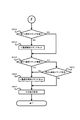
[主制御メイン処理]
次に、遊技制御用マイコン81の動作(主制御部による制御処理)について説明する。尚、遊技制御用マイコン81の動作説明にて登場するカウンタ、フラグ、ステータス、バッファ等は、主制御基板80のRAMに設けられている。主制御基板80に備えられた遊技制御用マイコン81は、パチンコ遊技機1の電源がオンされると、主制御基板80のROMから図10に示した主制御メイン処理のプログラムを読み出して実行する。同図に示すように、主制御メイン処理では、まず初期設定を行う(S101)。初期設定では例えば、スタックの設定、定数設定、割り込み時間の設定、主制御基板80のCPUの設定、SIO、PIO、CTC(割り込み時間用コントローラ)の設定や、各種のフラグ、ステータス及びカウンタのリセット等を行う。フラグの初期値は「0」つまり「OFF」であり、ステータスの初期値は「1」であり、カウンタの初期値は「0」である。尚初期設定(S101)は、電源投入後に一度だけ実行され、それ以降は実行されない。尚、実施例1及び図面において、普通図柄を「普図」、特別図柄を「特図」、第1特別図柄を「特図1」「第1特図」、第2特別図柄を「特図2」「第2特図」ということがある。
[Main control main processing]
Next, the operation of the game control microcomputer 81 (control processing by the main control unit) will be described. The counters, flags, statuses, buffers, etc. that appear in the operation description of the
初期設定(S101)に次いで、割り込みを禁止し(S102)、普通図柄・特別図柄主要乱数更新処理(S103)を実行する。この普通図柄・特別図柄主要乱数更新処理(S103)では、図7に示した種々の乱数カウンタの値を1加算する更新を行う。各乱数カウンタの値は上限値に至ると「0」に戻って再び加算される。尚各乱数カウンタの初期値は「0」以外の値であってもよく、ランダムに変更されるものであってもよい。更新された乱数カウンタ値は主制御基板80のRAMの所定の更新値記憶領域(図示せず)に逐次記憶される。
Following the initial setting (S101), interrupts are disabled (S102), and normal symbol / special symbol main random number update processing (S103) is executed. In this normal symbol / special symbol main random number update process (S103), the values of the various random number counters shown in FIG. 7 are updated by one. When the value of each random number counter reaches the upper limit, it returns to "0" and is added again. The initial value of each random number counter may be a value other than "0" or may be randomly changed. The updated random number counter values are sequentially stored in a predetermined updated value storage area (not shown) of the RAM of the
普通図柄・特別図柄主要乱数更新処理(S103)が終了すると、割り込みを許可する(S104)。割り込み許可中は、割り込み処理(S105)の実行が可能となる。この割り込み処理(S105)は、例えば4ms周期で主制御基板80のCPUに繰り返し入力される割り込みパルスに基づいて実行される。そして、割り込み処理(S105)が終了してから、次に割り込み処理(S105)が開始されるまでの間に、普通図柄・特別図柄主要乱数更新処理(S103)による各種カウンタ値の更新処理が繰り返し実行される。尚、割り込み禁止状態のときにCPUに割り込みパルスが入力された場合は、割り込み処理(S105)はすぐには開始されず、割り込み許可(S104)がされてから開始される。
When the normal symbol / special symbol main random number update process (S103) is completed, the interrupt is enabled (S104). While interrupts are enabled, interrupt processing (S105) can be executed. This interrupt processing (S105) is executed based on an interrupt pulse that is repeatedly input to the CPU of the
[割り込み処理]
次に、割り込み処理(S105)について説明する。図11に示すように、割り込み処理(S105)では、まず出力処理(S201)を実行する。出力処理(S201)では、以下に説明する各処理において主制御基板80のRAMに設けられた出力バッファにセットされたコマンド(制御信号)等を、サブ制御基板90や払出制御基板110等に出力する。ここで出力するコマンド等には、遊技状態、特別図柄当否判定の結果、大当り種別としての図柄、変動パターン等に関する情報等が挙げられる。尚、コマンドは、例えば2バイトの情報からなる。上位1バイトは、コマンドの種類に関する情報であり、下位1バイトはコマンドの内容に関する情報である。
[Interrupt processing]
Next, interrupt processing (S105) will be described. As shown in FIG. 11, in the interrupt processing (S105), the output processing (S201) is first executed. In the output process (S201), commands (control signals) set in the output buffer provided in the RAM of the
出力処理(S201)に次いで行われる入力処理(S202)では、主にパチンコ遊技機1に取り付けられている各種センサ(第1始動口センサ20a、第2始動口センサ21a、第1大入賞口センサ30a、第2大入賞口センサ35a、一般入賞口センサ27a等(図5参照))が検知した検知信号を読み込み、賞球情報としてRAMの出力バッファに記憶する。また、第1始動口センサ20aや第2始動口センサ21aが遊技球を検知した場合、後述の始動入球時処理(S205)により、各始動口に対応する始動入球コマンドをRAMの出力バッファに記憶する。さらに、下皿62の満杯を検知する下皿満杯スイッチからの検知信号も取り込み、下皿満杯データとしてRAMの出力バッファに記憶する。
In the input process (S202) performed after the output process (S201), various sensors (first
次に行われる普通図柄・特別図柄主要乱数更新処理(S203)は、図10の主制御メイン処理で行う普通図柄・特別図柄主要乱数更新処理(S103)と同じである。即ち、図7に示した各種乱数カウンタ値(普通図柄乱数カウンタ値も含む)の更新処理は、タイマ割り込み処理(S105)の実行期間と、それ以外の期間(割り込み処理(S105)の終了後、次の割り込み処理(S105)が開始されるまでの期間)との両方で行われている。 The normal symbol / special symbol main random number update process (S203) performed next is the same as the normal symbol / special symbol main random number update process (S103) performed in the main control main process of FIG. That is, the update processing of the various random number counter values (including the normal symbol random number counter value) shown in FIG. 7 is performed after the execution period of the timer interrupt processing (S105) and the other periods (after the end of the interrupt processing (S105)). It is performed both in the period until the next interrupt processing (S105) is started).
普通図柄・特別図柄主要乱数更新処理(S203)に次いで、後述する始動口センサ検知処理(S204)、始動入球時処理(S205)、普図動作処理(S206)、特図動作処理(S207)、特定領域センサ検知処理(S208)、保留球数処理(S209)および電源断監視処理(S210)を実行する。この他、遊技を進行させる上で必要な「その他の処理」を実行して、割り込み処理(S105)を終了する。そして、次に主制御基板80のCPUに割り込みパルスが入力されるまでは主制御メイン処理のS102〜S104の処理が繰り返し実行され(図10参照)、割り込みパルスが入力されると(約4msec後)、再び割り込み処理(S105)が実行される。再び実行された割り込み処理(S105)の出力処理(S201)においては、前回の割り込み処理(S105)にてRAMの出力バッファにセットされたコマンド等が出力される。
Following the normal symbol / special symbol main random number update process (S203), the start port sensor detection process (S204), start ball entry process (S205), normal diagram operation process (S206), and special symbol operation process (S207), which will be described later. , Specific area sensor detection process (S208), hold ball number process (S209), and power failure monitoring process (S210) are executed. In addition, the interrupt processing (S105) is terminated by executing "other processing" necessary for advancing the game. Then, until the next interrupt pulse is input to the CPU of the
[始動口センサ検知処理]
図12に示すように、始動口センサ検知処理(S204)ではまず、遊技球がゲート28を通過したか否か、即ち、ゲートセンサ28aによって遊技球が検知されたか否かを判定する(S301)。遊技球がゲート28を通過していれば(S301でYES)、普通図柄保留球数(普図保留の数、具体的にはRAMに設けた普図保留の数をカウントするカウンタの値)が4未満であるか否かを判定し(S302)、遊技球がゲート28を通過していなければ(S301でNO)、S305に進む。
[Starting port sensor detection process]
As shown in FIG. 12, in the start port sensor detection process (S204), first, it is determined whether or not the game ball has passed through the
普通図柄保留球数が4未満でなければ(S302でNO)、S305に進む。一方、普通図柄保留球数が4未満であれば(S302でYES)、普通図柄保留球数に「1」を加算し(S303)、普通図柄乱数取得処理(S304)を行う。普通図柄乱数取得処理(S304)では、RAMの更新値記憶領域(図示せず)に記憶されている普通図柄当否判定用乱数カウンタの値(ラベル−TRND−H、図7(B))を取得し、その取得乱数値(取得情報)を、主制御基板80のRAMに設けられた普図保留記憶部のうち現在の普通図柄保留球数に応じたアドレス空間に格納する。
If the number of normal symbol reserved balls is not less than 4 (NO in S302), proceed to S305. On the other hand, if the number of normal symbol reserved balls is less than 4 (YES in S302), "1" is added to the number of normal symbol reserved balls (S303), and the normal symbol random number acquisition process (S304) is performed. In the normal symbol random number acquisition process (S304), the value (label-TRND-H, FIG. 7B) of the random number counter for determining whether or not the normal symbol is correct or not stored in the update value storage area (not shown) of the RAM is acquired. Then, the acquired random number value (acquired information) is stored in the address space corresponding to the current number of ordinary symbol reserved balls in the normal symbol reserved storage unit provided in the RAM of the
S305では、第2始動口21に遊技球が入球したか否か、即ち、第2始動口センサ21aによって遊技球が検知されたか否かを判定する(S305)。第2始動口21に遊技球が入球していない場合(S305でNO)にはS309に進むが、第2始動口21に遊技球が入球した場合には(S305でYES)、特図2保留球数(第2特図保留の数、具体的には主制御部80のRAMに設けた第2特図保留の数をカウントするカウンタの数値)が4(上限数)未満であるか否かを判定する(S306)。そして、特図2保留球数が4未満でない場合(S306でNO)には、S309に進むが、特図2保留球数が4未満である場合には(S306でYES)、特図2保留球数に「1」を加算する(S307)。
In S305, it is determined whether or not the game ball has entered the
続いて特図2関係乱数取得処理(S308)を行う。特図2関係乱数取得処理(S308)では、RAMの更新値記憶領域(図示せず)に記憶されている特別図柄当否判定用乱数カウンタの値(ラベル−TRND−A)、大当り種別決定用乱数カウンタの値(ラベル−TRND−AS)、リーチ乱数カウンタの値(ラベル−TRND−RC)および変動パターン乱数カウンタの値(ラベル−TRND−T1)を取得し(つまり図7(A)に示す乱数の値を取得し)、それら取得乱数値(取得情報)を第2特図保留記憶部のうち現在の特図2保留球数に応じたアドレス空間に格納する。 Subsequently, the special figure 2 related random number acquisition process (S308) is performed. In the special figure 2 related random number acquisition process (S308), the value (label-TRND-A) of the random number counter for determining whether the special symbol is correct or not, and the random number for determining the jackpot type, which are stored in the update value storage area (not shown) of the RAM. The value of the counter (label-TRND-AS), the value of the reach random number counter (label-TRND-RC), and the value of the fluctuation pattern random number counter (label-TRND-T1) are acquired (that is, the random numbers shown in FIG. 7 (A)). (Acquire the value of), and store those acquired random number values (acquisition information) in the address space corresponding to the current number of reserved balls in the second special figure 2 in the second special figure reserved storage unit.
続いて始動口センサ検知処理(S204)では、第1始動口20に遊技球が入球したか否か、即ち、第1始動口センサ20aによって遊技球が検知されたか否かを判定する(S309)。第1始動口20に遊技球が入球していない場合(S309でNO)には処理を終えるが、第1始動口20に遊技球が入球した場合には(S309でYES)、特図1保留球数(第1特図保留数、具体的には主制御部80のRAMに設けた第1特図保留の数をカウントするカウンタの数値)が4(上限数)未満であるか否かを判定する(S310)。そして、特図1保留球数が4未満でない場合(S310でNO)には、処理を終えるが、特図1保留球数が4未満である場合には(S310でYES)、特図1保留球数に「1」を加算する(S311)。
Subsequently, in the start port sensor detection process (S204), it is determined whether or not the game ball has entered the
続いて特図1関係乱数取得処理(S312)を行う。特図1関係乱数取得処理(S312)では、特図2関係乱数取得処理(S308)と同様に、RAMの更新値記憶領域(図示せず)に記憶されている特別図柄当否判定用カウンタの値(ラベル−TRND−A)、大当り種別決定用乱数カウンタの値(ラベル−TRND−AS)、リーチ乱数カウンタの値(ラベル−TRND−RC)及び変動パターン乱数カウンタの値(ラベル−TRND−T1)を取得し(つまり図7(A)に示す乱数値を取得し)、それら取得乱数値(取得情報)を第1特図保留記憶部のうち現在の特図1保留球数に応じたアドレス空間に格納する。 Subsequently, the special figure 1 related random number acquisition process (S312) is performed. In the special figure 1 related random number acquisition process (S312), the value of the special symbol hit / miss determination counter stored in the update value storage area (not shown) of the RAM is the same as in the special figure 2 related random number acquisition process (S308). (Label-TRND-A), value of random number counter for determining jackpot type (label-TRND-AS), value of reach random number counter (label-TRND-RC), value of fluctuation pattern random number counter (label-TRND-T1) (That is, the random number values shown in FIG. 7A are acquired), and the acquired random number values (acquisition information) are stored in the address space according to the current number of reserved balls in the first special figure holding storage unit. Store in.
[始動入球時処理]
遊技制御用マイコン81は、図12に示した始動口センサ検知処理(S204)に次いで、図13に示す始動入球時処理(S205)を行う。始動入球時処理(S205)では、まず、特図2保留球数が「1」増加したか否かを判定する(S315)。この処理は、直前の始動口センサ検知処理(S204)におけるS307で特図2保留球数に「1」を加算している場合、特図2保留球数が「1」増加したと判定して(S315でYES)、S316に移行し、増加してなければ(S315でNO)、S319に移行する。S316では、直前の始動口センサ検知処理(S204)における特図2関係乱数取得処理(S308)で取得して第2特図保留記憶部に記憶した最新の取得乱数値(取得情報)を読み出し(S316)、読み出した取得乱数値の判定を行う(S317)。読み出した取得乱数値のうち、特別図柄当否判定用乱数カウンタの値(特別図柄当否判定用乱数値)については、現在の遊技状態に応じた大当り判定テーブル(図8(A)を参照)、すなわち、高確率状態であれば高確率状態用の大当り判定テーブル、通常状態(低確率状態)であれば通常状態用の大当り判定テーブルに基づいて、大当り判定値と一致するか否かを判定する。S317の処理は、後述の特図2当否判定処理(S1202)における当否判定(S1303,S1309)に先立って行う事前判定(所謂「保留先読み」)に相当するものである。
[Processing at the time of starting ball entry]
The
尚、特図保留記憶部(第1特図保留記憶部および第2特図保留記憶部)に記憶される取得乱数値(取得情報)のうち、大当り判定値と一致する特別図柄当否判定用乱数値のことを「特定取得情報」もしくは「大当り保留」ともいい、大当り判定値および小当り判定値と一致しない特別図柄当否判定用乱数値、すなわち外れ判定値のことを「非特定取得情報」もしくは「外れ保留」ともいう。また、小当り判定値と一致する特別図柄当否判定用乱数値のことを「所定取得情報」もしくは「小当り保留」ともいう。 Of the acquired random number values (acquired information) stored in the special figure holding storage unit (the first special figure holding storage unit and the second special figure holding storage unit), the special symbol hit / fail judgment random that matches the jackpot judgment value. The numerical value is also called "specific acquisition information" or "big hit hold", and the special symbol hit / fail judgment random value that does not match the big hit judgment value and the small hit judgment value, that is, the deviation judgment value is "non-specific acquisition information" or Also known as "holding off". Further, the random value for determining whether the special symbol is correct or not that matches the small hit determination value is also referred to as "predetermined acquisition information" or "small hit hold".
次いでS318では、S317の事前判定の結果を示す情報、具体的には、特別図柄当否判定用乱数値が大当り判定値と一致するか否かを示す情報(当否情報)、大当り種別決定用乱数カウンタの値(大当り種別決定用乱数値)を示す情報、リーチ乱数カウンタの値(リーチ乱数値)を示す情報および変動パターン乱数カウンタの値(変動パターン乱数値)を示す情報を含むコマンドデータを、始動入球コマンド(特図2始動入球コマンド)として生成し、この始動入球コマンドを主制御基板80のRAMに設けられたサブ制御基板90へのコマンド送信用の出力バッファにセットする(S318)。
Next, in S318, information indicating the result of the preliminary determination of S317, specifically, information indicating whether or not the random value for determining whether the special symbol is correct or not matches the jackpot determination value (win / fail information), and a random number counter for determining the jackpot type. Start command data including information indicating the value (random value for determining the jackpot type), information indicating the value of the reach random number counter (reach random value), and information indicating the value of the variable pattern random number counter (variable pattern random value). It is generated as an entry command (special figure 2 start entry command), and this start entry command is set in the output buffer for command transmission to the
次いでS319では、前述の特図2と同様に、特図1保留球数が「1」増加したか否かを判定する(S319)。この処理は、直前の始動口センサ検知処理(S204)におけるS311で特図1保留球数に「1」を加算している場合、特図1保留球数が「1」増加したと判定して(S319でYES)、S320に移行し、増加してなければ(S319でNO)、そのまま処理を終える。S320では、現在、通常遊技時の低ベース状態であるか否かを判定し(S320)、低ベース状態でなければ(S320でNO)、そのまま処理を終え、低ベース状態であれば(S320でYES)、S321以降の処理に進む。 Next, in S319, it is determined whether or not the number of reserved balls in Special Figure 1 has increased by "1", as in the case of Special Figure 2 described above (S319). In this process, when "1" is added to the number of reserved balls in special figure 1 in S311 in the immediately preceding start port sensor detection process (S204), it is determined that the number of reserved balls in special figure 1 has increased by "1". (YES in S319), shift to S320, and if it does not increase (NO in S319), the process ends as it is. In S320, it is judged whether or not it is in the low base state at the time of normal game (S320), if it is not in the low base state (NO in S320), the processing is finished as it is, and if it is in the low base state (in S320). YES), proceed to processing after S321.
S321〜S323の処理は、前述したS316〜S318と同様の処理を特図1について行うものである。すなわち、直前の始動口センサ検知処理(S204)における特図1関係乱数取得処理(S312)で取得して第1特図保留記憶部に記憶した最新の取得乱数値(取得情報)を読み出し(S321)、読み出した取得乱数値の事前判定を行い(S322)、この事前判定の結果を示す情報(当否情報、大当り種別決定用乱数値を示す情報、リーチ乱数値を示す情報、変動パターン乱数値を示す情報)を含むコマンドデータを、始動入球コマンド(特図1始動入球コマンド)として生成し、この始動入球コマンドを出力バッファにセットする(S323)。尚、S322の事前判定(保留先読み)は、後述の特図1当否判定処理(S1207)における当否判定(S1603,S1609)に先立って行うものである。 The processing of S321 to S323 is the same processing as that of S316 to S318 described above for the special figure 1. That is, the latest acquired random number value (acquisition information) acquired by the special figure 1 related random number acquisition process (S312) in the immediately preceding start port sensor detection process (S204) and stored in the first special figure hold storage unit is read out (S321). ), The read acquired random number value is pre-determined (S322), and the information indicating the result of this pre-determination (hit / fail information, information indicating the random value for determining the jackpot type, information indicating the reach random value, and the fluctuation pattern random value are obtained. Command data including the information shown) is generated as a start-in ball command (special figure 1 start-in ball command), and this start-in ball command is set in the output buffer (S323). The preliminary determination (holding look-ahead) of S322 is performed prior to the accuracy determination (S1603, S1609) in the special figure 1 accuracy determination process (S1207) described later.
ここで、高ベース状態では、第2始動口21への入球頻度が高まる開放延長機能が作動しており、特図2の当否判定(図8(B)を参照)が行われやすい状態となっている。また、本実施例では、後述するように特図2保留の消化(第2特別図柄の変動表示)を特図1保留の消化(第1特別図柄の変動表示)に優先して実行するものとしている。このことから、本実施例では、特図1保留に係る事前判定(特図1事前判定)を、第1特別図柄の変動表示が主体的に行われる低ベース状態にて行うこととし、特図2保留に係る事前判定(特図2事前判定)については、低ベース状態であるか高ベース状態であるかを問わず行うこととしている。
Here, in the high base state, the opening extension function that increases the frequency of entering the
また、本実施例のパチンコ遊技機1では、後述するように、大当り遊技中は低確低ベース状態に制御されるが、大当り遊技中に遊技球が第1始動口20に入球して特図1保留球数が「1」増加したとしても、S321〜S323の処理(特図1事前判定処理)は行わないものとなっている。
Further, in the
[普図動作処理]
遊技制御用マイコン81は、始動入球遊技処理(S206)に次いで、図14に示す普図動作処理(S207)を行う。普図動作処理(S207)では、普通図柄表示器42および可変入賞装置22に関する処理を4つの段階に分け、それらの各段階に「普図動作ステータス1、2、3、4」を割り当てている。そして、「普図動作ステータス」が「1」である場合には(S401でYES)、普通図柄待機処理(S402)を行い、「普図動作ステータス」が「2」である場合には(S401でNO、S403でYES)、普通図柄変動中処理(S404)を行い、「普図動作ステータス」が「3」である場合には(S401、S403で共にNO、S405でYES)、普通図柄確定処理(S406)を行い、「普図動作ステータス」が「4」である場合には(S401、S403、S405の全てがNO)、普通電動役物処理(S407)を行う。尚、普図動作ステータスは、初期設定では「1」である。
[Public map operation processing]
The
[普通図柄待機処理]
図15に示すように、普通図柄待機処理(S402)ではまず、普通図柄の保留球数が「0」であるか否かを判定し(S501)、「0」であれば(S501でYES)この処理を終える。一方「0」でなければ(S501でNO)、後述の普通図柄当否判定処理を行う(S502)。また、普通図柄当否判定処理(S502)に次いで、普通図柄変動パターン選択処理を行う(S503)。普通図柄変動パターン選択処理では、図8(E)に示す普通図柄変動パターン選択テーブルを参照して、遊技状態が時短状態であれば、普通図柄の変動時間が1秒の普通図柄変動パターンを選択する。一方、遊技状態が非時短状態であれば、普通図柄の変動時間が30秒の普通図柄変動パターンを選択する。また普通図柄変動パターン選択処理に次いで後述の普通図柄乱数シフト処理(S504)を行う。また、普通図柄乱数シフト処理(S504)に次いで、普通図柄変動開始処理を行い(S505)、処理を終える。普通図柄変動開始処理では、S503で選択した普通図柄変動パターンにて普通図柄の変動表示を開始するとともに、普通動作ステータスを「2」にセットする。また普通図柄変動開始処理では、サブ制御基板90に普通図柄の変動開始を知らせるため、普通図柄変動開始コマンドをセットする。
[Normal symbol standby processing]
As shown in FIG. 15, in the normal symbol standby process (S402), first, it is determined whether or not the number of reserved balls of the normal symbol is "0" (S501), and if it is "0" (YES in S501). This process is finished. On the other hand, if it is not "0" (NO in S501), the normal symbol hit / miss determination process described later is performed (S502). Further, following the normal symbol hit / fail determination process (S502), the normal symbol variation pattern selection process is performed (S503). In the normal symbol variation pattern selection process, the normal symbol variation pattern selection table shown in FIG. 8 (E) is referred to, and if the game state is a time saving state, a normal symbol variation pattern having a variation time of 1 second is selected. To do. On the other hand, if the gaming state is a non-time saving state, a normal symbol variation pattern having a normal symbol variation time of 30 seconds is selected. Further, after the normal symbol variation pattern selection process, the normal symbol random number shift process (S504) described later is performed. Further, following the normal symbol random number shift process (S504), the normal symbol variation start process (S505) is performed, and the process is completed. In the normal symbol variation start process, the variation display of the normal symbol is started with the normal symbol variation pattern selected in S503, and the normal operation status is set to "2". Further, in the normal symbol change start process, a normal symbol change start command is set in order to notify the
[普通図柄当否判定処理]
図16に示すように、普通図柄当否判定処理(S502)ではまず、普図保留記憶部に格納されている普通図柄当否判定用乱数カウンタの値(ラベル−TRND−H)を読み出す(S601)。次いで、時短フラグがONか否か(すなわち遊技状態が時短状態であるか否か)を判定する(S602)。S602で、時短フラグがONである、すなわち時短状態であると判定した場合(S602でYES)、図8(D)に示す普通図柄当り判定テーブルのうち時短状態用のテーブル(当り判定値が「0」〜「239」)に基づく高確率普図当否判定により、当りか否かを判定し(S604)、S605の処理に移行する。すなわち、読み出した普通図柄当否判定用乱数カウンタの値(ラベル−TRND−H)が当り判定値の何れかと一致するか否かを判定する。一方、S602で、時短フラグがONでない、すなわち、非時短状態であると判定した場合(S602でNO)、図8(D)に示す普通図柄当り判定テーブルのうち非時短状態用のテーブル(当り判定値が「0」、「1」)に基づく低確率普図当否判定により、当りか否かを判定し(S603)、S605の処理に移行する。そして、S605で、普図当否判定(S603、S604)の結果が、当り(普図当り)か否かを判定し(S605)、外れと判定した場合(S605でNO)、停止表示する外れ普通図柄(普図外れ図柄)を決定し(S606)、処理を終える。一方、S605で当り(普図当り)と判定した場合(S605でYES)、停止表示する当り普通図柄(普図当り図柄)を決定し(S607)、普図当りフラグをONにして(S608)、処理を終える。
[Ordinary symbol winning / failing judgment processing]
As shown in FIG. 16, in the normal symbol hit / miss determination process (S502), first, the value (label-TRND-H) of the normal symbol hit / miss determination random number counter stored in the normal symbol hold storage unit is read out (S601). Next, it is determined whether or not the time saving flag is ON (that is, whether or not the gaming state is the time saving state) (S602). When it is determined in S602 that the time saving flag is ON, that is, it is in the time saving state (YES in S602), among the normal symbol hit judgment tables shown in FIG. 8 (D), the table for the time saving state (the hit judgment value is "". Based on the high-probability normal-figure hit / fail judgment based on "0" to "239"), it is judged whether or not it is a hit (S604), and the process proceeds to S605. That is, it is determined whether or not the value (label-TRND-H) of the read random number counter for determining whether or not the normal symbol is correct matches any of the hit determination values. On the other hand, when it is determined in S602 that the time saving flag is not ON, that is, it is in the non-time saving state (NO in S602), the table for the non-time saving state (hit) among the normal symbol hit determination tables shown in FIG. 8 (D). Based on the low-probability normal-figure hit / fail judgment based on the judgment values "0" and "1"), it is judged whether or not it is a hit (S603), and the process proceeds to S605. Then, in S605, it is determined whether or not the result of the normal figure hit / fail judgment (S603, S604) is a hit (normal figure hit) (S605), and if it is judged to be a miss (NO in S605), the stop display is normal. Determine the symbol (the symbol that is out of the ordinary) (S606), and finish the process. On the other hand, when it is determined in S605 that it is a hit (a hit in a normal figure) (YES in S605), a normal symbol (a symbol per normal figure) to be stopped and displayed is determined (S607), and the normal figure hit flag is turned ON (S608). , Finish the process.
[普通図柄乱数シフト処理]
普通図柄変動パターン選択処理(S503)に次いで普通図柄乱数シフト処理(S504)を実行する。図17に示すように、普通図柄乱数シフト処理(S504)ではまず、普通図柄保留球数を1デクリメントする(S701)。次いで、普図保留記憶部における各普図保留の格納場所を、現在の位置から読み出される側に一つシフトする(S702)。そして、普図保留記憶部における最上位の保留記憶の格納場所であるアドレス空間を空(「0」)にして、即ち普図保留の4個目に対応するRAM領域を0クリアして(S703)、処理を終える。このようにして、普図保留が保留順に消化されるようにしている。
[Ordinary symbol random number shift processing]
Following the normal symbol variation pattern selection process (S503), the normal symbol random number shift process (S504) is executed. As shown in FIG. 17, in the normal symbol random number shift process (S504), first, the number of normal symbol reserved balls is decremented by 1 (S701). Next, the storage location of each Fuzu hold in the Fuzu hold storage unit is shifted by one to the side read from the current position (S702). Then, the address space, which is the storage location of the highest hold storage in the normal figure hold storage unit, is emptied (“0”), that is, the RAM area corresponding to the fourth hold of the normal figure is cleared to 0 (S703). ), Finish the process. In this way, the general map hold is digested in the order of hold.
[普通図柄変動中処理]
図18に示すように、普通図柄変動中処理(S404)ではまず、普通図柄の変動時間が経過したか否かを判定し(S801)、経過していなければ(S801でNO)処理を終える。一方、経過していれば(S801でYES)、普通図柄変動停止コマンドをセットする(S802)とともに、普図動作ステータスを「3」にセットする(S803)。そして、普通図柄の変動表示を、普通図柄当否判定用乱数の判定結果に応じた表示結果(当り普通図柄又は外れ普通図柄)で停止させる等のその他の処理を行ってから(S804)、この処理を終える。
[Processing during normal symbol change]
As shown in FIG. 18, in the normal symbol changing process (S404), first, it is determined whether or not the fluctuation time of the normal symbol has elapsed (S801), and if not, the process ends (NO in S801). On the other hand, if it has passed (YES in S801), the normal symbol fluctuation stop command is set (S802) and the normal symbol operation status is set to "3" (S803). Then, after performing other processing such as stopping the variable display of the normal symbol at the display result (hit normal symbol or out-of-order normal symbol) according to the judgment result of the random number for determining whether the normal symbol is correct or not (S804), this process is performed. To finish.
[普通図柄確定処理]
図19に示すように、普通図柄確定処理(S406)ではまず、普図当りフラグがONであるか否かを判定する(S901)。普図当りフラグがONでなければ(S901でNO)、普図動作ステータスを「1」にセットして(S905)、この処理を終える。一方、普図当りフラグがONであれば(S901でYES)、続いて時短フラグがONであるか否か、すなわち時短状態中か否かを判定する(S902)。そして時短状態中であれば(S902でYES)、可変入賞装置22(第2始動口21)の開放パターンとして時短状態中の開放パターンをセットする(S903)。時短状態中の開放パターンとは、前述の通り、2.0秒の開放を3回繰り返す開放パターンである。従って、第2始動口21の開放回数をカウントする第2始動口開放カウンタに「3」をセットする。
[Normal symbol confirmation process]
As shown in FIG. 19, in the normal symbol determination process (S406), first, it is determined whether or not the normal symbol hit flag is ON (S901). If the normal map hit flag is not ON (NO in S901), the normal figure operation status is set to "1" (S905), and this process ends. On the other hand, if the flag per normal figure is ON (YES in S901), then it is determined whether or not the time saving flag is ON, that is, whether or not the time saving state is in progress (S902). Then, if it is in the time saving state (YES in S902), the opening pattern in the time saving state is set as the opening pattern of the variable winning device 22 (second starting port 21) (S903). As described above, the opening pattern in the time saving state is an opening pattern in which the opening for 2.0 seconds is repeated three times. Therefore, "3" is set in the second start port opening counter that counts the number of times the
これに対して、非時短状態中であれば(S902でNO)、可変入賞装置22(第2始動口21)の開放パターンとして非時短状態中の開放パターンをセットする(S906)。非時短状態中の開放パターンとは、前述の通り、0.2秒の開放を1回行う開放パターンである。従って、第2始動口開放カウンタに「1」をセットする。そして、開放パターンのセット(S903、S906)に続いて、普図動作ステータスを「4」にセットし(S904)、この処理を終える。 On the other hand, if it is in the non-time saving state (NO in S902), the opening pattern in the non-time saving state is set as the opening pattern of the variable winning device 22 (second starting port 21) (S906). As described above, the opening pattern in the non-time saving state is an opening pattern in which opening for 0.2 seconds is performed once. Therefore, "1" is set in the second start port opening counter. Then, following the set of the open pattern (S903, S906), the normal figure operation status is set to "4" (S904), and this process is completed.
[普通電動役物処理]
図20に示すように、普通電動役物処理(S407)ではまず、普図当り終了フラグがONであるか否かを判定する(S1001)。普図当り終了フラグは、当りとなって実行された補助遊技において、第2始動口21の開放が終了したことを示すフラグである。
[Ordinary electric accessory processing]
As shown in FIG. 20, in the ordinary electric accessory processing (S407), first, it is determined whether or not the end flag per normal figure is ON (S1001). The normal figure hit end flag is a flag indicating that the opening of the
普図当り終了フラグがONでなければ(S1001でNO)、第2始動口21の開放中か否かを判定する(S1002)。開放中でなければ(S1002でNO)、第2始動口21を開放させる時期(タイミング)に至ったか否かを判定し(S1003)、至っていなければ(S1003でNO)処理を終え、至っていれば第2始動口21を開放させ(S1004)、処理を終える。一方、第2始動口21の開放中であれば(S1002でYES)、第2始動口21を閉鎖させる時期(タイミング)に至ったか否か(すなわち第2始動口21を開放してから予め定められた開放時間が経過したか否か)を判定し(S1005)、至っていなければ(S1005でNO)処理を終え、至っていれば(S1005でYES)第2始動口21を閉状態(閉鎖)とする(S1006)。
If the end flag per normal figure is not ON (NO in S1001), it is determined whether or not the
そして第2始動口21の閉鎖処理(S1006)に次いで、第2始動口開放カウンタの値を1デクリメントし(S1007)、第2始動口開放カウンタの値が「0」であるか否かを判定する(S1008)。「0」でなければ(S1008でNO)、再び第2始動口21を開放させるためにそのまま処理を終える。一方「0」であれば(S1008でYES)、補助遊技を終了させる普図当り終了処理を行う(S1009)とともに、普図当り終了フラグをセットして(S1010)処理を終える。尚、第2始動口開放カウンタは、時短状態中であれば第2始動口21の開放(可動部材23の開放動作)が3回なされると「0」になり、非時短状態中であれば第2始動口21の開放が1回なされると「0」になる。
Then, following the closing process of the second starting port 21 (S1006), the value of the second starting port opening counter is decremented by 1 (S1007), and it is determined whether or not the value of the second starting port opening counter is "0". (S1008). If it is not "0" (NO in S1008), the process is finished as it is in order to open the
これに対してS1001において普図当り終了フラグがONであれば(S1001でYES)、S903又はS906にてセットされた回数の第2始動口21の開放動作は終了しているので、普図当り終了フラグをOFFするとともに(S1011)、普図当りフラグをOFFし(S1012)、普図動作ステータスを「1」にセットして(S1013)処理を終える。これにより、次回の割り込み処理において、普図動作処理(図13)として再び普通図柄待機処理(S402)が実行されることになる。
On the other hand, if the end flag for hitting the normal figure is ON in S1001 (YES in S1001), the opening operation of the
[特図動作処理]
図11に示すように遊技制御用マイコン81は、普図動作処理(S206)に次いで特図動作処理(S207)を行う。特図動作処理(S207)では、図21に示すように、特別図柄表示器41および大入賞装置(第1大入賞装置31および第2大入賞装置36)に関する処理を5つの段階に分け、それらの各段階に「特図動作ステータス1、2、3、4、5」を割り当てている。そして、「特図動作ステータス」が「1」である場合には(S1101でYES)、特別図柄待機処理(S1102)を行い、「特図動作ステータス」が「2」である場合には(S1101でNO、S1103でYES)、特別図柄変動中処理(S1104)を行い、「特図動作ステータス」が「3」である場合には(S1101、S1103で共にNO、S1105でYES)、特別図柄確定処理(S1106)を行い、「特図動作ステータス」が「4」である場合には(S1101、S1103、S1105で共にNO、S1107でYES)、大当り遊技としての特別電動役物処理1(S1108)を行い、「特図動作ステータス」が「5」である場合には(S1101、S1103、S1105、S1107の全てがNO)、小当り遊技としての特別電動役物処理2(S1109)を行う。尚、特図動作ステータスは、初期設定では「1」である。
[Special figure operation processing]
As shown in FIG. 11, the
[特別図柄待機処理]
図22に示すように、特別図柄待機処理(S1102)ではまず、第2始動口21の保留球数(即ち特図2保留球数)が「0」であるか否かを判定する(S1201)。特図2保留球数が「0」である場合(S1201でYES)、即ち、第2始動口21への入球に基づいて取得される乱数カウンタ値の記憶がない場合には、第1始動口20の保留球数(即ち特図1保留球数)が「0」であるか否かを判定する(S1206)。そして、特図1保留球数も「0」である場合(S1206でYES)、即ち、第1始動口20への入球に基づいて取得される乱数カウンタ値の記憶もない場合には、画像表示装置7の表示画面7aを待機画面とする処理中(客待ち用のデモ画面の実行中)であるか否かを判定し(S1211)、そうであれば(S1211でYES)処理を終え、そうでなければ(S1211でNO)待機画面を表示するために待機画面設定処理を実行する(S1212)。
[Special symbol standby processing]
As shown in FIG. 22, in the special symbol standby process (S1102), first, it is determined whether or not the number of reserved balls in the second starting port 21 (that is, the number of reserved balls in special figure 2) is “0” (S1201). .. Special figure 2 When the number of reserved balls is "0" (YES in S1201), that is, when the random number counter value acquired based on the entry into the
S1201において特図2保留球数が「0」でない場合(S1201でNO)、即ち、第2始動口21への入球に基づいて取得される乱数カウンタ値の記憶が1つ以上ある場合には、後述の特図2当否判定処理(S1202)、特図2変動パターン選択処理(S1203)、特図2乱数シフト処理(S1204)、特図2変動開始処理(S1205)をこの順に行う。また、特図2保留球数が「0」であるが特図1保留球数が「0」でない場合(S1201でYES、S1206でNO)、即ち、第2始動口21に係る乱数カウンタ値の記憶はないが、第1始動口20への入球に基づいて取得される乱数カウンタ値の記憶が1つ以上ある場合には、後述の特図1当否判定処理(S1207)、特図1変動パターン選択処理(S1208)、特図1乱数シフト処理(S1209)、特図1変動開始処理(S1210)をこの順に行う。このように本実施例では、第1特図保留に基づく第1特別図柄の変動表示は、第2特図保留が「0」の場合(S1201でYESの場合)に限って行われる。すなわち第2特図保留の消化(第2特別図柄の変動表示)は、第1特図保留の消化(第1特別図柄の変動表示)に優先して実行される。そして本実施例では、第2特図保留に基づく当否判定の方が、第1特図保留に基づく当否判定よりも、遊技者にとって利益の大きい大当りになりやすくなっている(図8(B))。
In S1201, when the number of reserved balls in Special Figure 2 is not "0" (NO in S1201), that is, when there is one or more memory of the random number counter value acquired based on the entry into the
[特図2当否判定処理]
図23に示すように、特図2当否判定処理(S1202)ではまず、判定値として、RAMの特図保留記憶部の最下位の領域(即ち第2特図保留の1個目に対応するRAM領域)に記憶されている(最も古い記憶の)特別図柄当否判定用乱数カウンタの値(ラベル−TRND−A)を読み出す(S1301)。次いで、確変フラグがONか否か、すなわち高確率状態であるか否かを判定する(S1302)。そして、高確率状態でなければ(S1302でNO)、すなわち通常状態であれば、大当り判定テーブル(図8(A))のうち通常状態用の大当り判定テーブル(大当り判定値が「3」及び「397」)に基づいて当否判定を行う(S1303)。一方、高確率状態であれば(S1302でYES)、大当り判定テーブル(図8(A))のうち高確率状態用の大当り判定テーブルに基づいて当否判定を行う(S1309)。高確率状態用の大当り判定テーブルでは、大当り判定値は、「3」、「53」、「113」、「173」、「227」、「281」、「337」、「397」、「449」、「503」とされている。
[Special Figure 2 Win / Loss Judgment Process]
As shown in FIG. 23, in the special figure 2 hit / miss determination process (S1202), first, as a determination value, the lowest area of the special figure hold storage unit of the RAM (that is, the RAM corresponding to the first RAM of the second special figure hold). The value (label-TRND-A) of the random number counter for determining whether the special symbol is correct or not (the oldest stored) stored in the area) is read out (S1301). Next, it is determined whether or not the probability variation flag is ON, that is, whether or not it is in a high probability state (S1302). Then, if it is not in the high probability state (NO in S1302), that is, if it is in the normal state, the jackpot determination table for the normal state (the jackpot determination values are "3" and "" in the jackpot determination table (FIG. 8A)). A hit / fail judgment is made based on "397") (S1303). On the other hand, if it is in the high probability state (YES in S1302), the hit / fail judgment is performed based on the big hit determination table for the high probability state in the jackpot determination table (FIG. 8 (A)) (S1309). In the jackpot determination table for high probability states, the jackpot determination values are "3", "53", "113", "173", "227", "281", "337", "397", "449". , "503".
当否判定(S1303、S1309)の結果が「大当り」と判定した場合(S1304でYES)、大当り種別決定用乱数カウンタの値(ラベル−TRND−AS)を読み出して、図8(B)に示す大当り種別判定テーブルに基づいて大当り種別を判定し(S1310)、当該大当り種別決定用乱数の値に基づいて大当り図柄を決定し(S1311)、大当りフラグをONにして(S1312)、処理を終える。尚、第1特別図柄に係る当否判定の場合は、第1特別図柄用の大当り種別判定テーブルを用いて大当り種別を判定し、第2特別図柄に係る当否判定の場合は、第2特別図柄用の大当り種別判定テーブルを用いて大当り種別を判定する。また、第1特別図柄(特図1)の当否判定にて大当りと判定した場合は、15R第1大当り、15R第2大当り及び2R第3大当りのうち何れかが実行される。また、第2特別図柄(特図2)の当否判定にて大当りと判定した場合は、全て15R第4大当りとされる(図8(B))。ここで、大当り判定(特別図柄当否判定)や大当り種別決定判定を、夫々「判定」といってもよいし、大当り判定を行い何れの大当り図柄となるかを含めて「判定」といってもよい。また、これらの結果を「判定結果」ということもある。 When the result of the hit / fail judgment (S1303, S1309) is judged as "big hit" (YES in S1304), the value (label-TRND-AS) of the random number counter for determining the big hit type is read out and the big hit shown in FIG. 8 (B) is read. The jackpot type is determined based on the type determination table (S1310), the jackpot symbol is determined based on the value of the random number for determining the jackpot type (S1311), the jackpot flag is turned ON (S1312), and the process is completed. In the case of the hit / fail judgment related to the first special symbol, the jackpot type is judged using the jackpot type judgment table for the first special symbol, and in the case of the hit / fail judgment related to the second special symbol, it is for the second special symbol. The jackpot type is determined using the jackpot type determination table of. Further, when it is determined as a big hit in the hit / fail judgment of the first special symbol (special figure 1), any one of the 15R first big hit, the 15R second big hit, and the 2R third big hit is executed. Further, when the hit / fail judgment of the second special symbol (special figure 2) is determined to be a big hit, all of them are 15R fourth big hits (FIG. 8 (B)). Here, the jackpot judgment (special symbol hit / fail judgment) and the jackpot type determination judgment may be referred to as "judgment", respectively, or may be referred to as "judgment" including which jackpot symbol will be obtained by performing the jackpot judgment. Good. In addition, these results may be referred to as "judgment results".
また、大当りフラグには、大当りの種別が15R第1大当り、15R第2大当り又は15R第4大当りであった場合にONする長当りフラグと、2R第3大当りであった場合にONする短当りフラグとがある。ここで、ラウンド表示器45は、2R用ランプと15R用ランプとの2個のLEDで構成されており、2R第3大当りとなって短当りフラグがONにされると、2R第3大当り図柄が確定表示するタイミングで、2R用ランプの方が点灯表示される。具体的には、「2R▲15R△」(例えば、▲:点灯、△:消灯とする)の様な表示態様となる。また、15R第1大当り、15R第2大当り、及び15R第4大当りの何れかとなって長当りフラグがONにされると、対応する大当り図柄が確定表示するタイミングで、15R用ランプの方が点灯表示される。具体的には、「2R△15R▲」の様な表示態様となる。
In addition, the jackpot flag includes a long hit flag that is turned on when the type of jackpot is 15R first jackpot, 15R second jackpot, or 15R fourth jackpot, and a short hit that is turned on when the jackpot type is 2R third jackpot. There is a flag. Here, the
一方、当否判定(S1303、S1309)の結果が「大当り」でないと判定した場合(S1304でNO)、小当りか否かを判定する(S1305)。すなわち、特別図柄当否判定用乱数カウンタの値(ラベル−TRND−A)が、小当り判定値である「101」〜「105」の何れかと一致するか否かを判定する(図8(A))。そして、「小当り」でないと判定した場合(S1305でNO)、外れ図柄を決定し(S1308)、処理を終える。つまり、当否判定(S1303、S1309)の結果が「大当り」でもなく「小当り」でもない場合は、その結果は「外れ」となる。一方、小当り判定(S1305)の結果が「小当り」であると判定した場合(S1305でYES)、小当り図柄を決定し(S1306)、小当りフラグをONにして(S1307)、処理を終える。尚、小当りか否かを決める乱数を、特別図柄当否判定用乱数とは別に設けてもよい。 On the other hand, when it is determined that the result of the hit / fail determination (S1303, S1309) is not a "big hit" (NO in S1304), it is determined whether or not it is a small hit (S1305). That is, it is determined whether or not the value (label-TRND-A) of the random number counter for determining whether the special symbol is correct or not matches any of the small hit determination values "101" to "105" (FIG. 8 (A)). ). Then, when it is determined that it is not a "small hit" (NO in S1305), the out-of-order symbol is determined (S1308), and the process is completed. That is, if the result of the hit / fail judgment (S1303, S1309) is neither a "big hit" nor a "small hit", the result is a "miss". On the other hand, when it is determined that the result of the small hit determination (S1305) is "small hit" (YES in S1305), the small hit symbol is determined (S1306), the small hit flag is turned ON (S1307), and the process is performed. Finish. In addition, a random number for determining whether or not it is a small hit may be provided separately from the random number for determining whether or not the special symbol is correct.
[特図2変動パターン選択処理]
特別図柄待機処理(図22)では、特図2当否判定処理(S1202)に次いで、特図2変動パターン選択処理を行う(S1203)。図24及び図25に示すように、特図2変動パターン選択処理(S1203)ではまず、遊技状態が時短状態か否か(時短フラグがONか否か)を判定する(S1401)。そして、時短状態でなければ(S1401でNO)、すなわち非時短状態であれば、大当りフラグがONか否かを判定し(S1402)、ONであれば(S1402でYES)、非時短状態中大当り用テーブル(図9に示す変動パターンテーブルのうち非時短状態かつ大当りに該当する部分)を参照して、変動パターン乱数カウンタ値(ラベル−TRND−T1)に基づいて変動パターンを選択する(S1403)。尚、変動パターンが決まれば変動時間も決まる。また本実施例では、非時短状態中大当り用テーブルは、大当りが長当り(15R大当り)か短当り(2R大当り)かによっても分かれている。しかし本処理は、特図2についての変動パターン選択処理なので、特図2の抽選にて当選する大当りには15R第4大当り(長当り)しかない。従って本処理にて参照される箇所は、常に長当りの箇所となり、変動パターンP1または変動パターンP2が選択される。尚、非時短状態中大当り用テーブルは、長当り用と短当り用とに分かれていなくてもよい。これは後述の時短状態中大当り用テーブルについても同様である。
[Special figure 2 fluctuation pattern selection process]
In the special symbol standby process (FIG. 22), the special figure 2 variation pattern selection process is performed (S1203) after the special figure 2 hit / fail determination process (S1202). As shown in FIGS. 24 and 25, in the special figure 2 variation pattern selection process (S1203), first, it is determined whether or not the game state is the time saving state (whether or not the time saving flag is ON) (S1401). Then, if it is not in the time saving state (NO in S1401), that is, if it is in the non-time saving state, it is determined whether or not the jackpot flag is ON (S1402), and if it is ON (YES in S1402), it is a medium jackpot in the non-time saving state. The fluctuation pattern is selected based on the fluctuation pattern random number counter value (label-TRND-T1) with reference to the table (the portion of the fluctuation pattern table shown in FIG. 9 that corresponds to the non-time saving state and the jackpot) (S1403). .. If the fluctuation pattern is decided, the fluctuation time is also decided. Further, in this embodiment, the table for medium big hit in the non-time saving state is divided according to whether the big hit is a long hit (15R big hit) or a short hit (2R big hit). However, since this process is a variable pattern selection process for the special figure 2, the big hit won in the lottery of the special figure 2 is only the 15R fourth big hit (long hit). Therefore, the portion referred to in this process is always the location of the long hit, and the fluctuation pattern P1 or the fluctuation pattern P2 is selected. The table for medium and large hits in the non-time saving state does not have to be divided into a long hit table and a short hit table. This also applies to the table for medium and large hits in a time-saving state, which will be described later.
一方、大当りフラグがONでなければ(S1402でNO)、小当りフラグがONか否かを判定する(S1405)。そして、小当りフラグがONであれば(S1405でYES)、非時短状態中小当り用テーブル(図9に示す変動パターンテーブルのうち非時短状態かつ小当りに該当する部分)を参照して、変動パターン乱数カウンタ値に基づいて変動パターンを選択する(S1409)。具体的には、本実施例では必ず変動パターンP4が選択される。 On the other hand, if the big hit flag is not ON (NO in S1402), it is determined whether or not the small hit flag is ON (S1405). Then, if the small hit flag is ON (YES in S1405), the variation is made with reference to the non-time saving state medium / small hit table (the portion of the fluctuation pattern table shown in FIG. 9 that corresponds to the non-time saving state and small hit). Pattern A variation pattern is selected based on the random number counter value (S1409). Specifically, in this embodiment, the variation pattern P4 is always selected.
また、小当りフラグがONでなければ(S1405でNO)、リーチ乱数カウンタ値(ラベル−TRND−RC)がリーチ成立乱数値か否かを判定する(S1406)。図8(C)に示すように、リーチ成立乱数値は時短状態であれば「0」〜「5」であり、非時短状態であれば「0」〜「13」である。すなわち、時短状態の方が非時短状態よりも外れ時のリーチがかかりにくくなっている。これは、時短状態において変動時間の短いリーチ演出無し外れがより多く選択されようにすることで、特図保留の消化スピードを早めるためである。 If the small hit flag is not ON (NO in S1405), it is determined whether or not the reach random number counter value (label-TRND-RC) is the reach establishment random number value (S1406). As shown in FIG. 8C, the reach establishment random number values are “0” to “5” in the time saving state and “0” to “13” in the non-time saving state. That is, the time-saving state is less likely to reach when the time is off than the non-time-saving state. This is to accelerate the digestion speed of the special figure hold by allowing more non-reach effect deviations with a short fluctuation time to be selected in the time saving state.
リーチ乱数カウンタ値(ラベル−TRND−RC)がリーチ成立乱数値である場合(S1406でYES)、即ち、リーチ有外れの場合には、非時短状態中リーチ有外れ用テーブル(図9に示す変動パターンテーブルのうち非時短状態かつリーチ有外れに該当する部分)を参照して、変動パターン乱数カウンタ値に基づいて変動パターンを選択する(S1407)。本実施例では、変動パターンP5又はP6が選択される。 When the reach random number counter value (label-TRND-RC) is the reach establishment random number value (YES in S1406), that is, when the reach is out of reach, the table for out of reach in the non-time saving state (variation shown in FIG. 9). The fluctuation pattern is selected based on the fluctuation pattern random number counter value by referring to the non-time saving state (the part corresponding to the reach / non-reach state) in the pattern table (S1407). In this embodiment, the variation pattern P5 or P6 is selected.
リーチ乱数カウンタ値(ラベル−TRND−RC)がリーチ成立乱数値でない場合(S1406でNO)、即ち、リーチ無外れの場合には、非時短状態中リーチ無外れ用テーブル(図9に示す変動パターンテーブルのうち非時短状態かつリーチ無外れに該当する部分)を参照して、変動パターン乱数カウンタ値に基づいて変動パターンを選択する(S1408)。このリーチ無外れ時には、保留球数に応じた短縮変動の機能が働くようになっている。すなわち、特別図柄の保留球数が「3」又は「4」であるときは、特別図柄の保留球数が「1」又は「2」であるときに比して変動時間の短い変動パターンが選択されるようになっている。本実施例では、変動パターンP7又はP8が選択される。 If the reach random number counter value (label-TRND-RC) is not a reach-established random number value (NO in S1406), that is, if there is no reach, the table for no reach loss during the non-time saving state (variation pattern shown in FIG. 9). The variation pattern is selected based on the variation pattern random number counter value by referring to the non-time saving state (the part corresponding to the non-reachless state) in the table (S1408). When this reach does not come off, the function of shortening fluctuation according to the number of reserved balls works. That is, when the number of reserved balls of the special symbol is "3" or "4", a fluctuation pattern having a shorter fluctuation time than when the number of reserved balls of the special symbol is "1" or "2" is selected. It is supposed to be done. In this embodiment, the variation pattern P7 or P8 is selected.
またS1401において、遊技状態が時短状態であると判定した場合(S1401でYES)には、図25に示すように、参照する変動パターンテーブルを時短状態中用のテーブル(図9に示す変動パターンテーブルのうち時短状態に該当する部分)にする事以外は、上記ステップS1402〜S1409と同様の流れで処理(S1410〜S1416)を行う。すなわち、大当りであれば図9の時短状態中かつ大当りに該当する部分を参照し、小当りであれば図9の時短状態中かつ小当りに該当する部分を参照し、リーチ有外れであれば図9の時短状態中かつリーチ有外れに該当する部分を参照し、リーチ無外れであれば図9の時短状態中かつリーチ無外れに該当する部分を参照して、変動パターン乱数カウンタ値に基づいて変動パターンを選択する。 Further, in S1401, when it is determined that the gaming state is the time saving state (YES in S1401), as shown in FIG. 25, the fluctuation pattern table to be referred to is the table for the time saving state (the fluctuation pattern table shown in FIG. 9). Processing (S1410 to S1416) is performed in the same flow as in steps S1402 to S1409 above, except that the part corresponding to the time saving state) is set. That is, if it is a big hit, refer to the part corresponding to the time saving state and the big hit in FIG. 9, if it is a small hit, refer to the part corresponding to the time saving state and the small hit in FIG. Based on the fluctuation pattern random number counter value, refer to the part corresponding to the time saving state and reach non-off in FIG. 9, and refer to the part corresponding to the time saving state and reach non-off in FIG. 9 if there is no reach. And select the fluctuation pattern.
尚、時短状態中の変動パターンテーブル(図9に示す変動パターンテーブルのうち時短状態に該当する部分)では、リーチ無外れ時の保留球数に応じた短縮変動の機能が保留球数「2」〜「4」のときに働く(変動パターンP17)。すなわち、非時短状態中よりも短縮変動が選択され易くなっている。また、大当りのうち長当りに当選した場合に、非時短状態中よりも変動時間の短い変動パターン(変動パターンP10,P11)が選択され易くなっている。つまり、時短状態中の変動パターンテーブルは、非時短状態中の変動パターンテーブルよりも特別図柄の変動時間の平均値が短くなるようなテーブルとなっている。 In the fluctuation pattern table during the time saving state (the part corresponding to the time saving state in the fluctuation pattern table shown in FIG. 9), the function of shortening fluctuation according to the number of reserved balls when the reach is not off is the number of reserved balls "2". It works when ~ "4" (variation pattern P17). That is, the shortening variation is more likely to be selected than in the non-time saving state. Further, when the long hit is won among the big hits, the fluctuation patterns (variation patterns P10 and P11) having a shorter fluctuation time than in the non-time saving state are easily selected. That is, the fluctuation pattern table in the time saving state is a table in which the average value of the fluctuation time of the special symbol is shorter than the fluctuation pattern table in the non-time saving state.
前述のようにして変動パターンの選択を行った後は、図24に示すその他の処理(S1404)を行ってこの処理を終える。尚、その他の処理(S1404)では、選択した変動パターンに応じた変動パターン指定コマンド(特図2対応の変動パターン指定コマンド)をRAMの出力バッファにセットする。セットした変動パターン指定コマンドは、後述の変動開始コマンドに含められて、出力処理(S201)によりサブ制御基板90に送られる。
After selecting the variation pattern as described above, another process (S1404) shown in FIG. 24 is performed to finish this process. In the other processing (S1404), a variation pattern specification command (variation pattern specification command corresponding to Special Figure 2) corresponding to the selected variation pattern is set in the output buffer of the RAM. The set fluctuation pattern specification command is included in the fluctuation start command described later, and is sent to the
[特図2乱数シフト処理]
図26に示すように、特図2乱数シフト処理(S1204)ではまず、特図2保留球数を1デクリメントする(S1501)。次いで、第2特図保留記憶部における各種カウンタ値の格納場所を、1つ下位側(例えば第2特図保留記憶部がアドレス「0000」〜「0003」に対応するアドレス空間からなる場合、アドレス「0000」側)にシフトする(S1502)。そして、第2特図保留記憶部の最上位のアドレス空間に「0」をセットして、即ち、(上限数まで記憶されていた場合)第2特図保留の4個目に対応するRAM領域を0クリアして(S1503)、この処理を終える。
[Special Figure 2 Random number shift processing]
As shown in FIG. 26, in the special figure 2 random number shift process (S1204), first, the number of reserved balls in the special figure 2 is decremented by 1 (S1501). Next, when the storage location of various counter values in the second special figure reservation storage unit is one lower side (for example, when the second special figure reservation storage unit consists of the address space corresponding to the addresses "0000" to "0003", the address. Shift to the "0000" side) (S1502). Then, "0" is set in the uppermost address space of the second special figure reservation storage unit, that is, the RAM area corresponding to the fourth item of the second special figure reservation (when the upper limit number is stored). Is cleared to 0 (S1503), and this process is completed.
特図2乱数シフト処理(S1204)を実行した後は、図22の特図2変動開始処理(S1205)を実行する。特図2変動開始処理(S1205)では、特図動作ステータスを「2」にセットすると共に、変動開始コマンドをRAMの出力バッファにセットして、第2特別図柄の変動表示を開始する。 After executing the special figure 2 random number shift process (S1204), the special figure 2 fluctuation start process (S1205) of FIG. 22 is executed. In the special figure 2 fluctuation start processing (S1205), the special figure operation status is set to "2", the fluctuation start command is set in the output buffer of the RAM, and the fluctuation display of the second special symbol is started.
図22の特別図柄待機処理(S1102)において、特図2保留球数が「0」であり、かつ、特図1保留球数が「0」でない場合(S1201でYES、S1206でNO)には、特図1当否判定処理(S1207)、特図1変動パターン選択処理(S1208)、特図1乱数シフト処理(S1209)、特図1変動開始処理(S1210)をこの順に行う。 In the special symbol standby process (S1102) of FIG. 22, when the number of reserved balls in special figure 2 is "0" and the number of reserved balls in special figure 1 is not "0" (YES in S1201, NO in S1206). , Special figure 1 hit / fail determination process (S1207), special figure 1 fluctuation pattern selection process (S1208), special figure 1 random number shift process (S1209), and special figure 1 fluctuation start process (S1210) are performed in this order.
[特図1当否判定処理]
図27に示すように、特図1当否判定処理(S1207)では、図23に示した特図2当否判定処理(S1202)と同様の流れで処理(S1601〜S1612)を行う。従って本処理の詳細な説明は省略する。
[Special Figure 1 Win / Loss Judgment Process]
As shown in FIG. 27, in the special figure 1 hit / fail determination process (S1207), the processes (S1601 to S1612) are performed in the same flow as the special figure 2 hit / fail determination process (S1202) shown in FIG. 23. Therefore, a detailed description of this process will be omitted.
但し、本処理は特図1に関する処理であるので、S1601では、RAMの第1特図保留記憶部の最下位の領域(即ち第1特図保留の1個目に対応するRAM領域)に記憶されている特別図柄当否判定用乱数カウンタ値(ラベル−TRND−A)を読み出す。またS1610における大当りの種別判定では、15R第1大当り、15R第2大当り及び2R第3大当りのいずれとも判定される可能性がある(図8(B))。図8(B)の第1特別図柄(特図1)の欄に示すように、各大当りの振分率は、15R第1大当りが40%、15R第2大当りが50%、2R第3大当りが10%となっている。この大当りの種別判定で15R第1大当りまたは15R第2大当りと判定した場合には、ステップS1612において大当りフラグとして長当りフラグをONする。一方、2R第3大当りと判定した場合には、S1612において大当りフラグとして短当りフラグをONする。 However, since this process is related to the special figure 1, in S1601, it is stored in the lowest area of the first special figure hold storage unit of the RAM (that is, the RAM area corresponding to the first one of the first special figure hold). The random number counter value (label-TRND-A) for determining whether or not the special symbol is correct is read out. Further, in the type determination of the jackpot in S1610, there is a possibility that any of the 15R first jackpot, the 15R second jackpot, and the 2R third jackpot is determined (FIG. 8B). As shown in the column of the first special symbol (special figure 1) in FIG. 8B, the distribution rate of each jackpot is 40% for the 15R first jackpot, 50% for the 15R second jackpot, and 2R third jackpot. Is 10%. When it is determined that the 15R first jackpot or the 15R second jackpot is determined by the type determination of the jackpot, the long hit flag is turned ON as the jackpot flag in step S1612. On the other hand, when it is determined that the 2R third big hit, the short hit flag is turned ON as the big hit flag in S1612.
[特図1変動パターン選択処理]
図28及び図29に示すように、特図1変動パターン選択処理(S1208)では、図24及び図25に示した特図2変動パターン選択処理(S1203)と同様の流れで処理(S1701〜S1720)を行う。従って本処理の詳細な説明は割愛する。
[Special Figure 1 Fluctuation pattern selection process]
As shown in FIGS. 28 and 29, in the special figure 1 variation pattern selection process (S1208), processing (S1701 to S1720) is performed in the same flow as the special figure 2 variation pattern selection process (S1203) shown in FIGS. 24 and 25. )I do. Therefore, a detailed description of this process is omitted.
但し、本処理は特図1に関する処理であるので、S1702(図28))でYESの場合(すなわち大当りフラグがONの場合)には、さらに大当りの種別が15R大当り(15R第1大当りまたは15R第2大当り)であるか否かを判定する(S1703)。そして15R大当りである場合には(S1703でYES)、非時短状態中15R大当り用テーブル(図9に示す変動パターンテーブルのうち非時短状態かつ長当りに該当する部分)を参照して、変動パターン乱数カウンタ値(ラベル−TRND−T1)に基づいて変動パターンを選択する(S1704)。具体的には、変動パターンP1または変動パターンP2が選択される。 However, since this process is related to special figure 1, if YES in S1702 (FIG. 28) (that is, when the jackpot flag is ON), the jackpot type is 15R jackpot (15R first jackpot or 15R). It is determined whether or not it is the second big hit) (S1703). If it is a 15R jackpot (YES in S1703), refer to the 15R jackpot table in the non-time saving state (the part of the fluctuation pattern table shown in FIG. 9 corresponding to the non-time saving state and the long hit), and the fluctuation pattern. The variation pattern is selected based on the random number counter value (label-TRND-T1) (S1704). Specifically, the fluctuation pattern P1 or the fluctuation pattern P2 is selected.
一方、S1703において15R大当りでないと判定した場合(S1703でNO)、即ち2R第3大当りである場合には、非時短状態中2R大当り用テーブル(図9に示す変動パターンテーブルのうち非時短状態かつ短当りに該当する部分)を参照して、変動パターン乱数カウンタ値に基づいて変動パターンを選択する(S1706)。具体的には、変動パターンP3が選択される。 On the other hand, when it is determined in S1703 that it is not a 15R jackpot (NO in S1703), that is, when it is a 2R third jackpot, the 2R jackpot table in the non-time saving state (the fluctuation pattern table shown in FIG. 9 is in the non-time saving state and The fluctuation pattern is selected based on the fluctuation pattern random number counter value with reference to the part corresponding to the short hit (S1706). Specifically, the fluctuation pattern P3 is selected.
また、この特図1変動パターン選択処理では、S1712(図29)でYESの場合(すなわち大当りフラグがONの場合)にも、さらに大当りの種別が15R大当り(15R第1大当りまたは15R第2大当り)であるか否かを判定する(S1713)。そして15R大当りである場合には(S1713でYES)、時短状態中15R大当り用テーブル(図9に示す変動パターンテーブルのうち時短状態かつ長当りに該当する部分)を参照して、変動パターン乱数カウンタ値に基づいて変動パターンを選択する(S1714)。具体的には、変動パターンP9〜P11のいずれかが選択される。 Further, in this special figure 1 fluctuation pattern selection process, even when YES in S1712 (FIG. 29) (that is, when the jackpot flag is ON), the jackpot type is 15R jackpot (15R first jackpot or 15R second jackpot). ) (S1713). If it is a 15R jackpot (YES in S1713), refer to the 15R jackpot table in the time saving state (the part of the fluctuation pattern table shown in FIG. 9 corresponding to the time saving state and the long hit), and the fluctuation pattern random number counter. Select a variation pattern based on the value (S1714). Specifically, any of the fluctuation patterns P9 to P11 is selected.
一方、S1713において15R大当りでないと判定した場合(S1713でNO)、即ち2R第3大当りである場合には、時短状態中2R大当り用テーブル(図9に示す変動パターンテーブルのうち時短状態かつ短当りに該当する部分)を参照して、変動パターン乱数カウンタ値に基づいて変動パターンを選択する(S1715)。具体的には、変動パターンP12が選択される。 On the other hand, when it is determined in S1713 that it is not a 15R jackpot (NO in S1713), that is, when it is a 2R third jackpot, the 2R jackpot table in the time saving state (the time saving state and the short hit in the variation pattern table shown in FIG. 9). The fluctuation pattern is selected based on the fluctuation pattern random number counter value with reference to (the part corresponding to) (S1715). Specifically, the fluctuation pattern P12 is selected.
この特図1変動パターン選択処理において、変動パターンの選択(S1704、S1706、S1709、S1710、S1711、S1714、S1715、S1718、S1719、S1720)を行った後は、その他の処理(S1705、図29)を行って、この処理を終える。その他の処理(S1705)では、選択した変動パターンに応じた変動パターン指定コマンド(特図1対応の変動パターン指定コマンド)をRAMの出力バッファにセットする。セットした変動パターン指定コマンドは、後述の変動開始コマンドに含められて、出力処理(S201)によりサブ制御基板90に送られる。
In this special figure 1 variation pattern selection process, after the variation pattern is selected (S1704, S1706, S1709, S1710, S1711, S1714, S1715, S1718, S1719, S1720), other processes (S1705, FIG. 29) are performed. To finish this process. In the other processing (S1705), a variation pattern specification command corresponding to the selected variation pattern (variation pattern specification command corresponding to the special figure 1) is set in the output buffer of the RAM. The set fluctuation pattern specification command is included in the fluctuation start command described later, and is sent to the
[特図1乱数シフト処理]
図30に示すように、特図1乱数シフト処理(S1209)ではまず、特図1保留球数を1デクリメントする(S1801)。次いで、第1特図保留記憶部における各種カウンタ値の格納場所を、1つ下位側にシフトする(S2002)。そして、第1特図保留記憶部の最上位のアドレス空間に「0」をセットして、即ち、(上限数まで記憶されていた場合)第1特図保留の4個目に対応するRAM領域を0クリアして(S1803)、この処理を終える。
[Special Figure 1 Random number shift processing]
As shown in FIG. 30, in the special figure 1 random number shift process (S1209), first, the number of reserved balls in the special figure 1 is decremented by 1 (S1801). Next, the storage location of various counter values in the first special figure reservation storage unit is shifted to the lower side by one (S2002). Then, "0" is set in the uppermost address space of the first special figure reservation storage unit, that is, the RAM area corresponding to the fourth item of the first special figure reservation (when the upper limit number is stored). Is cleared to 0 (S1803), and this process is completed.
特図1乱数シフト処理(S1209)を実行した後は、図22の特図1変動開始処理(S1210)を実行する。特図1変動開始処理(S1210)では、特図動作ステータスを「2」にセットすると共に、変動開始コマンドをRAMの出力バッファにセットして、第1特別図柄の変動表示を開始する。 After executing the special figure 1 random number shift process (S1209), the special figure 1 fluctuation start process (S1210) of FIG. 22 is executed. In the special figure 1 fluctuation start processing (S1210), the special figure operation status is set to "2", the fluctuation start command is set in the output buffer of the RAM, and the fluctuation display of the first special symbol is started.
[特別図柄変動中処理]
図31に示すように、特別図柄変動中処理(S1104)ではまず、特別図柄の変動時間(図23のS1203又はS1208で選択された変動パターンに応じて決まる変動時間、図9参照)が経過したか否かを判定する(S1901)。変動時間が経過していないと判定した場合(S1901でNO)、処理を終える。これにより特別図柄の変動表示が継続される。
[Processing during special symbol change]
As shown in FIG. 31, in the special symbol variation processing (S1104), first, the variation time of the special symbol (the variation time determined according to the variation pattern selected in S1203 or S1208 of FIG. 23, see FIG. 9) has elapsed. Whether or not it is determined (S1901). If it is determined that the fluctuation time has not elapsed (NO in S1901), the process ends. As a result, the variable display of the special symbol is continued.
一方、変動時間が経過したと判定した場合(S1901でYES)、変動停止コマンドをセットする(S1902)。そして、確変フラグがONか否かを判定し(S1903)、ONであれば(S1903でYES)、確変カウンタを1減算し(S1904)、確変カウンタの値が「0」か否かを判定する(S1905)。S1905で確変カウンタが「0」であると判定した場合、確変フラグをOFFし、S1907の処理に移行する。一方、確変フラグがONでないと判定した場合(S1903でNO)、及び確変カウンタが「0」でないと判定した場合(S1905でNO)、S1907の処理に移行する。 On the other hand, if it is determined that the fluctuation time has elapsed (YES in S1901), the fluctuation stop command is set (S1902). Then, it is determined whether or not the probability variation flag is ON (S1903), if it is ON (YES in S1903), the probability variation counter is subtracted by 1 (S1904), and it is determined whether or not the value of the probability variation counter is "0". (S1905). When the probability change counter is determined to be "0" in S1905, the probability change flag is turned off and the process proceeds to S1907. On the other hand, when it is determined that the probability variation flag is not ON (NO in S1903) and when it is determined that the probability variation counter is not "0" (NO in S1905), the process proceeds to S1907.
そしてS1907では、時短フラグがONか否かを判定し(S1907)、時短フラグがONであると判定した場合(S1907でYES)、時短状態中に実行した特別図柄の変動表示回数をカウントする時短カウンタの値を1減算し(S1908)、時短カウンタの値が「0」か否かを判定し(S1909)、「0」であれば(S1909でYES)、時短フラグをOFFにし(S1910)、S1911の処理に進む。また、時短フラグがONでないと判定した場合(S1907でNO)および時短カウンタの値が「0」でないと判定した場合(S1909でNO)、S1911の処理に進む。S1911では、特図動作ステータスを「3」にセットする(S1911)。そして、特別図柄の変動表示を、特別図柄当否判定乱数及び大当り種別決定用乱数の判定結果に応じた結果で停止させる等のその他の処理を行い(S1912)、この処理を終える。 Then, in S1907, when it is determined whether or not the time saving flag is ON (S1907) and when it is determined that the time saving flag is ON (YES in S1907), the time saving for counting the number of fluctuation display times of the special symbol executed during the time saving state The counter value is subtracted by 1 (S1908), it is determined whether or not the time saving counter value is "0" (S1909), and if it is "0" (YES in S1909), the time saving flag is turned off (S1910). Proceed to the processing of S1911. Further, when it is determined that the time saving flag is not ON (NO in S1907) and when it is determined that the value of the time saving counter is not "0" (NO in S1909), the process proceeds to S1911. In S1911, the special figure operation status is set to "3" (S1911). Then, other processing such as stopping the variable display of the special symbol at a result corresponding to the determination result of the special symbol winning / failing determination random number and the big hit type determination random number is performed (S1912), and this processing is completed.
[特別図柄確定処理]
図32に示すように、特別図柄確定処理(S1106)ではまず、大当りフラグがONであるか否かを判定する(S2001)。大当りフラグがONであれば(S2001でYES)、続いて大当りの種別が15R大当り(15R第1大当り、15R第2大当り及び15R第4大当りのいずれか)か否かを判定する(S2002)。そして、15R大当りであれば(すなわち長当りフラグがONであれば)、大当り遊技中に実行するラウンド(1ラウンド1回開放の態様では、1回のラウンドは大入賞口の開放から閉塞まで)の回数をカウントするラウンドカウンタの値を「15」にセットするとともに、大入賞口(第1大入賞口30又は第2大入賞口35)の開放パターンとして、15R第1大当りであれば15R第1大当り用の開放パターン(図6参照)をセットし、15R第2大当りであれば15R第2大当り用の開放パターン(図6参照)をセットし、15R第4大当りであれば15R第4大当り用の開放パターン(図6参照)をセットする(S2003)。
[Special symbol confirmation process]
As shown in FIG. 32, in the special symbol determination process (S1106), first, it is determined whether or not the jackpot flag is ON (S2001). If the jackpot flag is ON (YES in S2001), it is subsequently determined whether or not the jackpot type is 15R jackpot (either 15R first jackpot, 15R second jackpot, or 15R fourth jackpot) (S2002). Then, if it is a 15R jackpot (that is, if the long hit flag is ON), a round to be executed during the jackpot game (in the mode of opening one round once, one round is from opening the big winning opening to closing). The value of the round counter that counts the number of times is set to "15", and as an opening pattern of the big winning opening (1st big winning
S2002において15R大当りでなければ(すなわち短当りフラグがONであれば)、大当り種別は2R第3大当りであるため、ラウンドカウンタの値を「2」にセットするとともに、大入賞口(第1大入賞口30又は第2大入賞口35)の開放パターンとして、2R第3大当り用の開放パターン(図6参照)をセットする(S2004)。
If it is not a 15R jackpot in S2002 (that is, if the short hit flag is ON), the jackpot type is 2R 3rd jackpot, so the value of the round counter is set to "2" and the jackpot (1st jackpot) As the opening pattern of the winning
S2003又はS2004の処理を終えたら、大当り遊技を開始するべく、大当りのオープニングコマンドをセットするとともに(S2005)、大当り遊技のオープニング演出を開始し(S2006)、特図動作ステータスを「4」にセットする(S2007)。 After finishing the processing of S2003 or S2004, in order to start the jackpot game, set the jackpot opening command (S2005), start the jackpot game opening production (S2006), and set the special figure operation status to "4". (S2007).
また、S2001において大当りフラグがONでないと判定した場合(S2001でNO)、小当りフラグがONであるか否かを判定する(S2008)。小当りフラグがONであれば(S2008でYES)、小当り遊技中における大入賞口(第2大入賞口35)の開放回数をカウントする小当り用開放カウンタの値を「2」にセットするとともに、大入賞口(第2大入賞口35)の開放パターンとして、小当り用の開放パターン(図6参照)をセットする(S2009)。 Further, when it is determined in S2001 that the big hit flag is not ON (NO in S2001), it is determined whether or not the small hit flag is ON (S2008). If the small hit flag is ON (YES in S2008), the value of the small hit opening counter that counts the number of times the large winning opening (second large winning opening 35) is opened during the small hit game is set to "2". At the same time, an opening pattern for small hits (see FIG. 6) is set as the opening pattern of the large winning opening (second large winning opening 35) (S2009).
S2009の処理を終えたら、小当り遊技を開始するべく、小当りのオープニングコマンドをセットするとともに(S2010)、小当り遊技のオープニング演出を開始し(S2011)、特図動作ステータスを「5」にセットする(S2012)。尚、S2008において小当りフラグがONでなければ(S2008でNO)、大当り遊技も小当り遊技も開始しないため、特図動作ステータスを「1」にセットし、処理を終える。 After finishing the processing of S2009, in order to start the small hit game, set the small hit opening command (S2010), start the small hit game opening production (S2011), and set the special figure operation status to "5". Set (S2012). If the small hit flag is not ON in S2008 (NO in S2008), neither the big hit game nor the small hit game will start, so the special figure operation status is set to "1" and the process is completed.
[特別電動役物処理1(大当り遊技)]
図33に示すように、特別電動役物処理1(S1108)ではまず、確変フラグがONか否かを判定し(S2101)、ONと判定した場合(S2101でYES)、確変フラグをOFFする(S2102)。また、時短フラグがONか否かを判定し(S2103)、ONと判定した場合(S2103でYES)、時短フラグをOFFする(S2104)。つまり、大当り遊技の実行中は、低確率状態かつ非時短状態に制御される。本実施例では非時短状態時は常に低ベース状態であるので、大当り遊技の実行中は低確低ベース状態に制御されることにもなる。
[Special electric accessory processing 1 (big hit game)]
As shown in FIG. 33, in the special electric accessory process 1 (S1108), first, it is determined whether or not the probability change flag is ON (S2101), and when it is determined to be ON (YES in S2101), the probability change flag is turned OFF (S2101). S2102). Further, it is determined whether or not the time saving flag is ON (S2103), and when it is determined to be ON (YES in S2103), the time saving flag is turned OFF (S2104). That is, during the execution of the jackpot game, it is controlled to a low probability state and a non-time saving state. In this embodiment, since the low base state is always in the non-time saving state, the low probability low base state is also controlled during the execution of the jackpot game.
次に、大当り終了フラグがONであるか否かを判定する(S2105)。大当り終了フラグは、大当り遊技において大入賞口(第1大入賞口30及び第2大入賞口35)の開放が全て終了(大当り遊技が終了)したことを示すフラグである。大当り終了フラグがONでなければ(S2105でNO)、大入賞口(第1大入賞口30又は第2大入賞口35)の開放中か否かを判定する(S2106)。開放中でなければ(S2106でNO)、大入賞口(第1大入賞口30又は第2大入賞口35)を開放させる時期(タイミング)に至ったか否か、すなわち大当りのオープニングの時間が経過して1ラウンド目を開始する時期に至ったか、又は、ラウンド間のインターバルの時間が経過して次ラウンド(次の開放)を開始する時期に至ったか否かを判定する(S2107)。これは、前述した大当り種別毎に設定した大入賞口開放パターンに基づいて判定する。例えば、1ラウンド目の開始前であれば、オープニング期間が終了して1ラウンド目の最初の開放処理を実行するタイミングであるか否かによって判定する。また、既に1ラウンド目を開始した後であれば、前のラウンドが終了し、かつ、所定のインターバル期間が終了している否かによって判定する。尚、ラウンドを、単に「R」ともいい、「ラウンド遊技」ともいう。
Next, it is determined whether or not the jackpot end flag is ON (S2105). The jackpot end flag is a flag indicating that all the jackpots (
S2107の判定結果がNOであれば、そのまま処理を終える。一方、S2107の判定結果がYESであれば、実行されるラウンドが1ラウンド目及び2ラウンド目の何れかのラウンドに該当するか否かを判定する(S2108)。これは、大当り種別毎に、ラウンドカウンタの値を用いて判定してもよいし、別途実行するラウンドが何ラウンド目かをカウントするラウンドカウンタを設けて判定してもよい。1ラウンド目及び2ラウンド目のいずれのラウンドでもない(すなわち、3〜15ラウンドの何れか)場合(S2108でNO)、S2110に進んで、大当りの種類に応じた開放パターン(図6参照)に従って第1大入賞口30を開放させるべく、第1大入賞装置31を作動させる。一方、1ラウンド目又は2ラウンド目であると判定した場合(S2108でYES)、V有効期間設定処理(S2109)を行ってからS2110に進んで、大当りの種類に応じた開放パターン(図6参照)に従って第2大入賞口35を開放させるべく、第2大入賞装置36を作動させる。また、大入賞口(第1大入賞口30又は第2大入賞口35)を開放する際、すなわちラウンドを開始する際には、対応するラウンドのラウンド開始コマンドをセットする。例えば、1ラウンド目の開始であれば「1R開始コマンド」、2ラウンド目の開始であれば「2R開始コマンド」のように、開始するラウンドを特定可能なラウンド開始コマンドをセットする。セットしたラウンド開始コマンドは、S201の出力処理により、サブ制御部90に送信される。
If the judgment result of S2107 is NO, the process ends as it is. On the other hand, if the determination result of S2107 is YES, it is determined whether or not the executed round corresponds to either the first round or the second round (S2108). This may be determined by using the value of the round counter for each jackpot type, or may be determined by providing a round counter that counts the number of rounds to be executed separately. If neither the first round nor the second round (ie, any of the 3rd to 15th rounds) (NO in S2108), proceed to S2110 and follow the opening pattern according to the type of jackpot (see FIG. 6). The first prize-winning
V有効期間設定処理(S2109)では、1ラウンド又は2ラウンドにおける第2大入賞口35の開放中及び第2大入賞口35の閉鎖後の数秒間を、特定領域センサ39aによる遊技球の検知を有効と判定する期間(第1期間に相当)に設定する。尚、本実施例ではこれ以外の期間(小当り中や特別遊技を実行していないときも含む)は、特定領域センサ39aによる遊技球の検知を無効と判定する期間(第2期間に相当)に設定している。ここで、特定領域センサ39aによる遊技球の検知を有効と判定するというのは、特定領域センサ39aによる遊技球の検知に基づいてVフラグをONする(後述の特定領域センサ検知処理(図37)のステップS2401〜S2403参照)ということであり、特定領域センサ39aによる遊技球の検知を無効と判定するというのは、特定領域センサ39aによる遊技球の検知があってもVフラグをONしないということである。
In the V validity period setting process (S2109), the game ball is detected by the
ここで、特定領域センサ39aによって遊技球が検知され、VフラグがONになったタイミングで、遊技状態表示器46を所定の表示態様とし、大当り遊技終了後の遊技状態が高確率状態となることを報知する。具体的には、遊技状態表示器46は「a1a2a3」の3個のLEDで構成されている。そして、本実施例では、通常状態(低確率状態)においては、「a1□a2□a3□」(例えば、□:消灯、■:点灯)の表示態様とされる。また、大当り遊技中の特定領域センサ39aによって遊技球が検知され、VフラグがONになったタイミングで、「a1■a2■a3■」の表示態様とされる。そして、大当り遊技が終了し、遊技状態が高確率状態に設定されると「a1□a2□a3□」の表示態様とされる。また、遊技状態表示器46の点灯制御タイミングはこのようなタイミングに限定されず、大当り遊技中は、遊技球が特定領域を通過しても「a1□a2□a3□」の表示態様のままとし、大当り遊技終了後の高確率状態へ移行するタイミングで「a1■a2■a3■」とし、高確率状態から低確率状態に移行するタイミングで「a1□a2□a3□」の表示態様としてもよい。
Here, when the game ball is detected by the
すなわち、後述の特定領域センサ検知処理(図36)では、V有効期間中のV通過(特定領域39への遊技球の通過)の検知時のみVフラグをONし、V有効期間外(V無効期間中)のV通過検知時にはVフラグをONしないこととしている。尚、VフラグがONである場合には、確変フラグがONされる、すなわち大当り遊技後の遊技状態が高確率状態に設定される(後述の遊技状態設定処理(図34))。このようにすることで、不正行為によるV通過に基づいてVフラグがONされることのないように、すなわち不正に高確率状態に設定されることのないようにしている。 That is, in the specific area sensor detection process (FIG. 36) described later, the V flag is turned ON only when the V passage (passage of the game ball to the specific area 39) is detected during the V valid period, and the V flag is turned on outside the V valid period (V invalid). The V flag is not turned on when the V passage is detected (during the period). When the V flag is ON, the probability variation flag is ON, that is, the game state after the big hit game is set to a high probability state (game state setting process (FIG. 34, which will be described later)). By doing so, the V flag is not turned on based on the passage of V due to fraudulent activity, that is, it is prevented from being illegally set to a high probability state.
また、大当り遊技の1R目または2R目でV通過があれば、当該大当り遊技終了後の遊技状態を高確率状態に設定する一方で、小当り遊技中にV通過があっても、小当り遊技前の遊技状態が通常状態であれば、その小当り遊技終了後の遊技状態も通常状態とし、小当り遊技前の遊技状態が高確率状態であれば、その小当り遊技終了後の遊技状態も高確率状態とする。つまり、小当り遊技の前後で当否判定確率を変化させないようにしている。 Further, if there is a V pass in the 1st or 2nd round of the big hit game, the game state after the end of the big hit game is set to a high probability state, and even if there is a V pass during the small hit game, the small hit game If the previous game state is the normal state, the game state after the end of the small hit game is also the normal state, and if the game state before the small hit game is a high probability state, the game state after the end of the small hit game is also set. High probability state. That is, the probability of winning or failing is not changed before and after the small hit game.
尚、本実施例では、V有効期間設定処理(S2109)において、15R第2大当りである場合にも特定領域センサ39aによる遊技球の検知を有効と判定する期間(第1期間)に設定するが、他の態様として、15R第2大当りの場合は1R目及び2R目において第1期間を設定しないものとしてもよい。すなわち、15R第2大当りの場合は1R目及び2R目を第2期間に設定するようにしてもよい。15R第2大当りに係る大当り遊技では、第2大入賞口35の開放時間を0.1秒と極短時間に設定しているため遊技球が第2大入賞口35へ入球する可能性は限りなく低いが、第2期間に設定しておけば、万が一入球した場合でもVフラグがONになることはない。これにより、不正にVフラグをONにしたり、まれな入球によりVフラグがONになったりしてしまうのを防止することができる。尚、本実施例では1ラウンド又は2ラウンドにおいて特定領域センサ39aによる遊技球の検知を有効としているが、ラウンドの場所はこれに限らなくてもよい。
In this embodiment, in the V validity period setting process (S2109), the period (first period) in which the detection of the game ball by the
S2106において大入賞口(第1大入賞口30又は第2大入賞口35)の開放中であれば(S2106でYES)、そのラウンドにおける大入賞口への入球個数が規定の最大入球個数(本実施例では1ラウンド当り10個)に達しているか否かを判定する(S2111)。規定入球個数に達していなければ(S2111でNO)、大入賞口を閉鎖させる時期(タイミング)に至ったか否か、すなわち大入賞口を開放してから所定の開放時間(図6参照)が経過したか否かを判定する(S2112)。そして、大入賞口の開放時間が経過していなければ(S2112でNO)、処理を終える。
If the big winning opening (1st big winning
これに対して、規定入球個数に達している場合(S2111でYES)、又は大入賞口の開放時間が経過した場合(S2112でYES)、すなわち2つのラウンド終了条件のうちのいずれかが成立した場合には、大入賞口(第1大入賞口30又は第2大入賞口35)を閉鎖する(S2113)。そして、ラウンドカウンタの値を1デクリメントし(S2114)、ラウンドカウンタの値が「0」であるか否かを判定する(S2115)。「0」でないと判定した場合(S2115でNO)、次のラウンドを開始するため、処理を終える。また、大入賞口(第1大入賞口30又は第2大入賞口35)を閉鎖する際、すなわちラウンドを終了する際には、対応するラウンドのラウンド終了コマンドをセットする。例えば、1ラウンド目の終了であれば「1R終了コマンド」、2ラウンド目の終了であれば「2R終了コマンド」のように、終了するラウンドを特定可能なラウンド終了コマンドをセットする。このセットしたラウンド終了コマンドは、S201の出力処理により、サブ制御部90に送信される。尚、ラウンド終了コマンドは、大当り遊技の最終ラウンドを除くラウンドの終了の際、すなわち、S2115でラウンドカウンタの値が「0」でないと判定した場合に送信される。例えば、実行する大当り遊技のラウンド数が15R大当り遊技であれば、14Rの終了まではラウンド終了コマンドが送信されるが、15Rの終了に際しては送信されない。最終ラウンドの終了に際しては、後述するS2116の処理でセットするエンディングコマンドが送信されるからである。
On the other hand, when the specified number of balls has been reached (YES in S2111) or when the opening time of the big winning opening has passed (YES in S2112), that is, one of the two round end conditions is satisfied. If this happens, the big winning opening (1st big winning
一方、「0」と判定した場合(S2115でYES)、大当り遊技を終了させる大当り終了処理として、大当りのエンディングコマンドをセットするとともに(S2116)、大当りのエンディング演出を開始する(S2117)。そして、大当り終了フラグをセットし(S2118)、処理を終える。尚、ラウンドカウンタは、長当り(15R大当り)であれば大入賞口の開放が15回実行されると「0」になり、短当り(2R大当り)であれば大入賞口の開放が2回実行されると「0」になる。 On the other hand, when it is determined to be "0" (YES in S2115), the jackpot ending command is set (S2116) and the jackpot ending effect is started (S2117) as the jackpot ending process for ending the jackpot game. Then, the jackpot end flag is set (S2118), and the process is completed. If the round counter is a long hit (15R big hit), it will be "0" if the big winning opening is opened 15 times, and if it is a short hit (2R big hit), the big winning opening will be opened twice. When executed, it becomes "0".
またS2105において大当り終了フラグがONであれば(S2105でYES)、最終ラウンドが終了しているので、大当りのエンディング演出の実行時間(エンディング時間)が経過したか否かを判定し(S2119)、エンディング時間が経過していなければ(S2119でNO)、処理を終える。一方、エンディング時間が経過していれば(S2119でYES)、大当り終了フラグをOFFにした後(S2120)、後述の遊技状態設定処理(S2121)を行う。そして、大当りフラグをOFFにし(S2122)、特図動作ステータスを「1」にセットし(S2123)、処理を終える。これにより、次回の割り込み処理において、特図動作処理(図21)として再び特別図柄待機処理(S1102)が実行されることになる。以上の特別電動役物処理1(S1108)を実行する遊技制御用マイコン81は「特別遊技実行手段」として機能するものといえる。
If the jackpot end flag is ON in S2105 (YES in S2105), the final round has ended, so it is determined whether or not the execution time (ending time) of the jackpot ending effect has elapsed (S2119). If the ending time has not passed (NO in S2119), the process ends. On the other hand, if the ending time has elapsed (YES in S2119), after turning off the jackpot end flag (S2120), the game state setting process (S2121) described later is performed. Then, the jackpot flag is turned off (S2122), the special figure operation status is set to "1" (S2123), and the process is completed. As a result, in the next interrupt process, the special symbol standby process (S1102) is executed again as the special symbol operation process (FIG. 21). It can be said that the
[遊技状態設定処理]
図34に示すように、遊技状態設定処理(S2121)ではまず、VフラグがONであるかどうかを判定する(S2201)。Vフラグは後述の特定領域センサ検知処理(図36)にてONされるフラグである。そして、VフラグがONであれば(S2201でYES)、確変フラグをONにするとともに(S2202)、確変カウンタに「100」をセットし(S2203)、VフラグをOFFにし(S2204)、S2205の処理に進む。一方、VフラグがOFFであれば(S2201でNO)、確変フラグをONにすることなく、S2205の処理に進む。すなわち、本パチンコ遊技機1では、この遊技状態設定処理においてVフラグがONになっているか否かに基づいて、大当り遊技終了後の遊技状態を高確率状態に設定するか否かを決めている。
[Game status setting process]
As shown in FIG. 34, in the game state setting process (S2121), first, it is determined whether or not the V flag is ON (S2201). The V flag is a flag that is turned on in the specific area sensor detection process (FIG. 36) described later. Then, if the V flag is ON (YES in S2201), the probability variation flag is ON (S2202), the probability variation counter is set to "100" (S2203), the V flag is OFF (S2204), and S2205 Proceed to processing. On the other hand, if the V flag is OFF (NO in S2201), the process proceeds to S2205 without turning the probability change flag ON. That is, in the
S2205では、終了した大当り遊技(今回実行した大当り遊技)が15R大当りであるか否かを判定する。そして、15R大当りであると判定した場合(S2205でYES)、時短フラグをONにするとともに(S2207)、時短カウンタに「100」をセットし(S2208)、処理を終える。ここで、今回の大当り遊技が15R第1大当りに係るものであれば、当該大当り遊技中に遊技球が特定領域39(V通過)を通過してVフラグがONになっている筈なので(S2201でYES)、この場合の大当り遊技終了後の遊技状態は高確高ベース状態になる。また、今回の大当り遊技が15R第2大当りに係るものであれば、当該大当り遊技中にV通過せずVフラグがONになっていない筈なので(S2201でNO)、この場合の大当り遊技終了後の遊技状態は低確高ベース状態になる。 In S2205, it is determined whether or not the completed jackpot game (the jackpot game executed this time) is a 15R jackpot. Then, when it is determined that it is a 15R jackpot (YES in S2205), the time saving flag is turned ON (S2207), "100" is set in the time saving counter (S2208), and the process is completed. Here, if the jackpot game this time is related to the 15R first jackpot, the game ball should have passed through the specific area 39 (passing V) during the jackpot game and the V flag should be ON (S2201). YES), the game state after the big hit game in this case becomes a high accuracy and high base state. Also, if the jackpot game this time is related to the 15R second jackpot, V should not have passed during the jackpot game and the V flag should not be ON (NO in S2201), so after the jackpot game in this case is completed. The game state of is low accuracy and high base state.
一方、S2205で、終了した大当り遊技(今回実行した大当り遊技)が15R大当りでない、すなわち、2R第3大当りであると判定した場合(S2205でNO)、今回の大当り遊技開始前の遊技状態、すなわち2R第3大当りとなった際の遊技状態が時短状態であったか否かを判定し(S2209)、時短状態でなかったと判定した場合(S2209でNO)、時短フラグをONにすることなく、そのまま処理を終える。これにより、今回の大当り遊技でVフラグがONにならなかった場合(S2201でNO)、大当り遊技終了後の遊技状態は低確低ベース状態となり、今回の大当り遊技でVフラグがONになった場合(S2201でYES)、大当り遊技終了後の遊技状態は高確低ベース状態となる。 On the other hand, in S2205, when it is determined that the completed jackpot game (the jackpot game executed this time) is not a 15R jackpot, that is, it is a 2R third jackpot (NO in S2205), the game state before the start of this jackpot game, that is, If it is determined whether or not the game state at the time of the 2R 3rd big hit was the time saving state (S2209) and it is determined that the game state was not the time saving state (NO in S2209), the processing is performed as it is without turning on the time saving flag. To finish. As a result, if the V flag is not turned on in this big hit game (NO in S2201), the game state after the big hit game is in a low probability low base state, and the V flag is turned on in this big hit game. In the case (YES in S2201), the game state after the big hit game is high accuracy and low base state.
一方、S2209で、2R第3大当りとなった際の遊技状態が時短状態であったと判定した場合(S2209でYES)、時短フラグをONにするとともに(S2207)、時短カウンタに「100」をセットし(S2208)、処理を終える。これにより、今回の大当り遊技でVフラグがONにならなかった場合(S2201でNO)、大当り遊技終了後の遊技状態は低確高ベース状態となり、今回の大当り遊技でVフラグがONになった場合(S2201でYES)、大当り遊技終了後の遊技状態は高確高ベース状態となる。 On the other hand, if it is determined in S2209 that the game state at the time of the 2R 3rd big hit was the time saving state (YES in S2209), the time saving flag is turned ON (S2207) and "100" is set in the time saving counter. Then (S2208), the process is finished. As a result, if the V flag is not turned on in this big hit game (NO in S2201), the game state after the big hit game is in a low accuracy and high base state, and the V flag is turned on in this big hit game. In the case (YES in S2201), the game state after the big hit game ends is the high accuracy and high base state.
尚、高確高ベース状態、低確高ベース状態および高確低ベース状態は、いずれも、特別図柄が100回変動表示すること、及び、次の大当りが発生すること、の何れかの条件の成立により終了する。 The high-accuracy high-base state, the low-accuracy high-base state, and the high-accuracy low-base state are all under the conditions that the special symbol is fluctuated 100 times and the next big hit occurs. It ends when it is established.
また、2R第3大当りに係る大当り遊技開始前の遊技状態が時短状態かどうかを判定する処理(S2209)を行うのは、当該大当り遊技前後の時短機能および高ベース機能の作動状態を、小当りが発生した場合の状態(条件)と同じにするためである。これらの作動状態が2R第3大当りの場合と小当りの場合とで異なっていると、大入賞口の開放パターンで何れの当りかを認識し難くしたとしても、その後の遊技状態(時短機能および高ベース機能の作動状態)によって、何れの当りかが容易に判別可能となってしまうからである。これにより、2R第3大当りと小当りとを大入賞口の開放パターンによって判別し難くすると共に、その後の時短機能や高ベース発生機能の作動状態によっても判別し難くするものとしている。 Further, the process (S2209) of determining whether the game state before the start of the big hit game related to the 2R 3rd big hit is the time saving state is performed by determining the operating state of the time saving function and the high base function before and after the big hit game. This is to make it the same as the state (condition) when If these operating states are different between the case of the 2R 3rd big hit and the case of the small hit, even if it is difficult to recognize which hit is due to the opening pattern of the big winning opening, the subsequent gaming state (time saving function and time saving function and This is because it is possible to easily determine which hit is due to the operating state of the high base function). As a result, it is difficult to distinguish between the 2R third big hit and the small hit by the opening pattern of the big winning opening, and it is also difficult to distinguish by the operating state of the subsequent time saving function and the high base generation function.
[特別電動役物処理2(小当り遊技)]
図35に示すように、特別電動役物処理2(S1109)ではまず、小当り終了フラグがONであるか否かを判定する(S2301)。小当り終了フラグは、小当り遊技において第2大入賞口35の開放が全て終了したことを示すフラグである。小当り終了フラグがONでなければ(S2301でNO)、第2大入賞口35の開放中か否かを判定する(S2302)。開放中でなければ(S2302でNO)、大入賞口(第1大入賞口30又は第2大入賞口35)を開放させる時期(タイミング)に至ったか否か、すなわち小当りのオープニングの時間が経過して1回目の開放を開始する時期に至ったか、又は、複数回にわたる開放の間のインターバルの時間が経過して次の開放を開始する時期に至ったか否かを判定する(S2303)。S2303の判定結果がNOであれば、そのまま処理を終える。一方、S2303の判定結果がYESであれば、V無効期間設定処理(S2304)を行ってから、S2305に進み、小当りの開放パターン(図6参照)に従って第2大入賞口35を開放させるべく第2大入賞装置36を作動させる。
[Special electric accessory processing 2 (small hit game)]
As shown in FIG. 35, in the special electric accessory process 2 (S1109), first, it is determined whether or not the small hit end flag is ON (S2301). The small hit end flag is a flag indicating that all the opening of the second large winning
V無効期間設定処理(S2304)では、小当り遊技における第2大入賞口35の開放中および第2大入賞口35の閉鎖後の数秒間を、特定領域センサ39aによる遊技球の検知を無効と判定する期間(第2期間)に設定する。また、本実施例では、前述のV有効期間設定処理(S2109)で有効期間に定める期間以外の期間は無効期間(第2期間)とされている。従って、このV無効期間設定処理では、有効期間となっていないか、すなわち無効期間に設定されているかを確認する。具体的には、V有効期間の経過をカウントダウンにて計測するVタイマ(主制御基板80のRAMに設けられている)が「0」(すなわち有効期間無しの状態)に設定されているかを確認する。Vタイマが「0」でなければVタイマに「0」をセットする。尚Vタイマが「0」か否かを確認することなく、Vタイマに「0」をセットする即ち有効期間無しの状態に設定するようにしてもよい。これにより、小当り遊技中にV通過があっても、小当り遊技開始前の遊技状態が通常状態であれば、その小当り遊技終了後の遊技状態は高確率状態に移行しないようになる。尚、本実施例では、前述のV有効期間設定処理(S2109)で有効期間に定める期間以外の期間は無効期間であるため、S2304の処理を省略してもよい。
In the V invalid period setting process (S2304), the detection of the game ball by the
S2302において第2大入賞口35の開放中であれば、(S2302でYES)、2回の開放中における第2大入賞口35への入球個数、すなわち2回の開放において入球した遊技球を全て足した数が、規定の最大入球個数(本実施例では10個)に達しているか否かを判定する(S2306)。規定入球個数に達していなければ(S2306でNO)、第2大入賞口35を閉鎖させる時期に至ったか否か、すなわち第2大入賞口35を開放してから所定の開放時間(図6参照)が経過したか否かを判定する(S2307)。そして、第2大入賞口35の開放時間が経過していなければ(S2307でNO)、処理を終える。
If the second big winning
これに対して、2回の開放中における第2大入賞口35への入球個数が規定入球個数に達している場合(S2306でYES)、第2大入賞口35を閉鎖し(S2314)、S2311の小当り終了処理に移行する。一方、S2307で、第2大入賞口35の開放時間が経過したと判定した場合(S2307でYES)には、第2大入賞口35を閉鎖する(S2308)。そして、小当り用開放カウンタの値を1デクリメントし(S2309)、小当り用開放カウンタの値が「0」であるか否かを判定する(S2310)。S2310で「0」でないと判定した場合(S2310でNO)、次の開放を開始するため、そのまま処理を終える。
On the other hand, when the number of balls entered into the second large winning
一方、S2310で「0」であると判定した場合(S2310でYES)、S2311の小当り終了処理に移行する。S2311では、小当り遊技を終了させる小当り終了処理として、小当りのエンディングコマンドをセットするとともに(S2311)、小当りのエンディング演出を開始する(S2312)。そして、小当り終了フラグをセットし(S2313)、処理を終える。尚、小当り用開放カウンタは、第2大入賞口35の開放が2回なされると「0」になる。
On the other hand, when it is determined in S2310 that it is "0" (YES in S2310), the process proceeds to the small hit end processing of S2311. In S2311, as the small hit end process for ending the small hit game, the small hit ending command is set (S2311) and the small hit ending effect is started (S2312). Then, the small hit end flag is set (S2313), and the process is completed. The small hit opening counter becomes "0" when the second large winning
S2301において、小当り終了フラグがONであれば(S2301でYES)、2回の開放が終了しているので、小当りのエンディングの時間が経過したか否かを判定し(S2315)、エンディング時間が経過していなければ(S2315でNO)、処理を終える。一方、エンディング時間が経過していれば(S2315でYES)、小当り終了フラグをOFFにするとともに(S2316)、小当りフラグをOFFにし(S2317)、さらに、特図動作ステータスを「1」にセットし(S2318)、処理を終える。これにより、次回の割り込み処理において、特図動作処理(図20)として再び特別図柄待機処理(S1102)が実行されることになる。 In S2301, if the small hit end flag is ON (YES in S2301), since the opening of two times has been completed, it is determined whether or not the ending time of the small hit has passed (S2315), and the ending time. If has not passed (NO in S2315), the process ends. On the other hand, if the ending time has passed (YES in S2315), the small hit end flag is turned off (S2316), the small hit flag is turned off (S2317), and the special figure operation status is set to "1". Set (S2318) and finish the process. As a result, in the next interrupt process, the special symbol standby process (S1102) is executed again as the special symbol operation process (FIG. 20).
尚、小当り遊技の開始に際して確変フラグや時短フラグをONからOFFに切り変えることはしない。また、小当り遊技の終了に際しては、遊技状態設定処理(S2121、図36)を行わない。すなわち、本パチンコ遊技機1では、小当り遊技の実行前と実行後において遊技状態を変化させない。以上の特別電動役物処理2(S1109)を実行する遊技制御用マイコン81は「特別遊技実行手段」として機能するといえる。
At the start of the small hit game, the probability change flag and the time saving flag are not switched from ON to OFF. Further, at the end of the small hit game, the game state setting process (S2121, FIG. 36) is not performed. That is, in the
[特定領域センサ検知処理]
図11に示すように遊技制御用マイコン81は、特図動作処理(S208)に次いで特定領域センサ検知処理(S209)を行う。特定領域センサ検知処理(S209)では、図36に示すように、まず、特定領域センサ39aによる遊技球の検知があったか否かを判定し(S2401)、検知がないと判定した場合(S2401でNO)、処理を終了する。一方、S2401で検知があると判定した場合(S2401でYES)、V有効期間中か否かを判定する(S2402)。V有効期間は、前述の特別電動役物処理1(図33)におけるV有効期間設定処理(S2109)にて設定される期間である。V有効期間は、大当り遊技における1ラウンド目と2ラウンド目に設定される。
[Specific area sensor detection processing]
As shown in FIG. 11, the
また、S2402でV有効期間中であると判定した場合(S2402でYES)、VフラグをONにすると共に(S2403)、現在実行中の大当り遊技が2R大当り(2R第3大当り)であるか否かを判定する(S2404)。そして、2R大当りでないと判定した場合(S2404でNO)、すなわち15R大当りであれば、第1V通過コマンドをセットし(S2405)、処理を終える。一方、2R大当りであると判定した場合(S2404でYES)、第2V通過コマンドをセットし(S2406)、処理を終える。主制御基板80のCPUは、所定のタイミングでこのV通過コマンドをサブ制御基板90に送信し、サブ制御基板90は受信したV通過コマンドの種別によって、演出図柄表示領域等で遊技演出を実行する。
If it is determined in S2402 that the V is valid (YES in S2402), the V flag is turned ON (S2403), and whether or not the jackpot game currently being executed is a 2R jackpot (2R third jackpot). Is determined (S2404). Then, when it is determined that it is not a 2R jackpot (NO in S2404), that is, if it is a 15R jackpot, the first V pass command is set (S2405), and the process is completed. On the other hand, when it is determined that it is a 2R jackpot (YES in S2404), the second V passage command is set (S2406), and the process ends. The CPU of the
また、S2402でV有効期間中でないと判定した場合(S2402でNO)、VフラグをONにすることなく、第3V通過コマンドをセットし(S2407)、処理を終える。尚、第1V通過コマンドは、サブ制御基板90にV通過の報知制御を行わせるためのコマンドである。これに対して、第2V通過コマンド及び第3V通過コマンドは、サブ制御基板90にV通過の報知制御を原則行わせないためのコマンドである。また、遊技制御用マイコン81は、このような特定領域センサ検知処理(S208)やV有効期間設定処理(S2109)を実行することにより、特定領域39への遊技球の通過の有効無効を切り替える手段(特定領域状態切替手段)として機能する。
If it is determined in S2402 that the V valid period is not in effect (NO in S2402), the third V passage command is set (S2407) without turning on the V flag, and the process ends. The first V-passing command is a command for causing the
[保留球数処理]
図11に示すように遊技制御用マイコン81は、特定領域センサ検知処理(S208)に次いで保留球数処理(S209)を行う。保留球数処理(S208)では図37に示すように、まず、主制御基板80のRAMに記憶されている特図1保留球数、特図2保留球数及び普通図柄保留球数を読み出す(S2501)。次いで、その保留球数のデータ(その保留球数情報をサブ制御基板90等に送信するための保留球数コマンド)を、RAMの出力バッファにセットする(S2502)。尚、保留球数のデータについては、前述の始動入球時処理(S2041)で生成する始動入球コマンドに含めるものとしてもよい。
[Holded ball number processing]
As shown in FIG. 11, the
[電源断監視処理]
図11に示すように遊技制御用マイコン81は、保留球数処理(S209)に次いで電源断監視処理(S210)を行う。電源断監視処理(S210)では図38に示すように、まず、電源断信号の入力の有無を判定し(S2601)、入力がなければ(S2601でNO)、処理を終了する。一方、電源断信号の入力があれば(S2601でYES)、現在の遊技機の状態(確変かどうか、当り遊技中かどうか、保留球数はいくつか、確変・時短の残り変動回数はいくつか等)に関するデータをRAMに記憶するとともに(S2602)、電源断フラグをONし(S2603)、その後は割り込み処理(図11)に戻ることなくループ処理をする。
[Power failure monitoring process]
As shown in FIG. 11, the
[サブ制御メイン処理]
次に、演出制御用マイコン91の動作(演出制御部による制御処理)について説明する。尚、演出制御用マイコン91(サブ制御部90)は本発明の「演出実行手段」の一態様を示すものであり、以下の演出制御用マイコン91の動作説明にて登場するカウンタ、フラグ、ステータス、バッファ等は、サブ制御基板90(サブ制御部)のRAMに設けられている。サブ制御基板90に備えられた演出制御用マイコン91は、パチンコ遊技機1の電源がオンされると、サブ制御基板90のROMから図39に示すサブ制御メイン処理のプログラムを読み出して実行する。同図に示すように、サブ制御メイン処理では、まずCPU初期化処理を行う(S4001)。CPU初期化処理(S4001)では、スタックの設定、定数設定、CPU92の設定、SIO、PIO、CTC(割り込み時間用コントローラ)等の設定や各種のフラグ、ステータス及びカウンタのリセット等を行う。
[Sub-control main processing]
Next, the operation of the effect control microcomputer 91 (control processing by the effect control unit) will be described. The effect control microcomputer 91 (sub-control unit 90) shows one aspect of the "effect execution means" of the present invention, and the counters, flags, and statuses appearing in the following operation description of the
続いて、S4002で、電源断信号がONでかつサブ制御基板90のRAMの内容が正常であるか否かを判定する(S4002)。そして、この判定結果がNOであれば(S4002でNO)、サブ制御基板90のRAMの初期化をし(S4003)、S4004に進む。一方、判定結果がYESであれば(S4002でYES)、サブ制御基板90のRAMを初期化することなくS4004に進む。すなわち、電源断信号がONでない場合、又は電源断信号がONであってもRAMの内容が正常でない場合には(S4002でNO)、サブ制御基板90のRAMを初期化するが、停電などで電源断信号がONとなったがRAMの内容が正常に保たれている場合には(S4002でYES)、RAMを初期化しない。RAMを初期化すれば、各種のフラグ、ステータス及びカウンタの値はリセットされる。尚、このS4001〜S4003は、電源投入後に(電源投入に際して)一度だけ実行され、それ以降は実行されない。また、本実施例では、演出制御用マイコン91においても、図11に示す遊技制御用マイコン81による電源断監視処理(S210)と同様の処理を行うこととしており、停電などで電源断信号がONになると、そのときの演出制御に係るデータがサブ制御基板90のRAMに記憶されるものとなっている。つまり、停電などの電源断発生時における演出制御に係るデータがバックアップされるものとなっている。このため、停電等の電源断から復帰した後の電源投入時(電断復帰時)に、サブ制御基板90のRAMの初期化(S4003)が行われない限り、演出制御用マイコン91による演出制御の状態は電源断発生前の状態に復帰する。
Subsequently, the S4002 determines whether or not the power cutoff signal is ON and the contents of the RAM of the
S4004では、割り込みを禁止する。次いで、乱数シード更新処理を実行する(S4005)。乱数シード更新処理(S4005)では、種々の演出決定用乱数カウンタの値を更新する。更新された乱数カウンタ値はサブ制御基板90のRAMの所定の更新値記憶領域(図示せず)に逐次記憶される。尚、演出決定用乱数には、実行する演出図柄遊技演出の態様(変動演出パターン)を決定する変動演出決定用乱数や予告演出を決定する予告演出決定用乱数、演出図柄を決定する演出図柄決定用乱数等がある。乱数の更新方法は、前述の主制御基板80が行う乱数更新処理と同様の方法をとることができる。更新に際して乱数値を1ずつ加算するのではなく、2ずつ加算するなどしてもよい。演出決定用乱数は、予め定められたタイミングで取得される。このタイミングとしては、例えば主制御基板80から始動入球があった旨を通知する制御信号(始動入球コマンド)が送信されてきたときや、主制御基板80から変動開始を通知する制御信号(変動開始コマンド)が送信されてきたときや、後述の変動演出パターンを決定するときなどとすることができる。取得した演出決定用乱数の格納場所は、サブ制御基板90のRAMの所定の乱数カウンタ値記憶領域(図示せず)である。
The S4004 disables interrupts. Next, the random number seed update process is executed (S4005). In the random number seed update process (S4005), the values of various random number counters for determining the effect are updated. The updated random number counter values are sequentially stored in a predetermined updated value storage area (not shown) of the RAM of the
乱数シード更新処理(S4005)が終了すると、コマンド送信処理を実行する(S4006)。コマンド送信処理では、サブ制御基板90のRAM内の出力バッファに格納されている各種のコマンド(制御信号)を、画像制御基板100、音声制御基板106、及びランプ制御基板107に送信する。コマンドを受信した各制御基板(各制御部)は、受信したコマンドに従い各種の演出装置(画像表示装置7、スピーカ67、盤面ランプ5、枠ランプ66、第1演出可動部材14A、第2演出可動部材14B、第1演出ボタン63a、第2演出ボタン63b等)を用いて各種の演出(演出図柄遊技演出や、大当り遊技及び小当り遊技に伴う特別遊技演出等)を実行する(演出実行手段)。演出制御用マイコン91は続いて、割り込みを許可する(S4007)。以降、S4004〜S4007をループさせる。割り込み許可中においては、受信割り込み処理(S4008)、2msタイマ割り込み処理(S4009)および10msタイマ割り込み処理(S4010)の実行が可能となる。
When the random number seed update process (S4005) is completed, the command transmission process is executed (S4006). In the command transmission process, various commands (control signals) stored in the output buffer in the RAM of the
[受信割り込み処理]
受信割り込み処理(S4008)では、図40に示すように、ストローブ信号(STB信号)がONか否か、すなわち主制御基板80から送られたストローブ信号が演出制御用マイコン91の外部INT入力部に入力されたか否かを判定する(S4101)。そして、S4101で、ストローブ信号がONでないと判定した場合(S4101でNO)、処理を終える。一方、S4101で、ストローブ信号がONであると判定した場合(S4101でYES)、主制御基板80から送信されてきた各種のコマンドをサブ制御基板90のRAMに格納し(S4102)、処理を終える。この受信割り込み処理(S4008)は、他の割り込み処理(S4009、S4010)に優先して実行される処理である。
[Receive interrupt processing]
In the reception interrupt processing (S4008), as shown in FIG. 40, whether or not the strobe signal (STB signal) is ON, that is, the strobe signal sent from the
[2msタイマ割り込み処理]
2msタイマ割り込み処理(S4009)は、サブ制御基板90に2msec周期の割り込みパルスが入力する度に実行する処理である。図41に示すように、2msタイマ割り込み処理(S4009)ではまず、演出ボタン検知スイッチ63c、63dからの検知信号に基づいてスイッチデータ(エッジデータ及びレベルデータ)を作成する入力処理を行う(S4201)。続いて、後述の10msタイマ割り込み処理で作成したランプデータを出力するランプデータ出力処理を行う(S4202)。次いで、第1演出可動部材14Aや第2演出可動部材14B、第2演出ボタン63b等の各種演出可動部材(第1演出駆動源14a、第2演出駆動源14bおよび第3演出駆動源14c)を駆動するための駆動データを出力する駆動データ出力処理を行う(S4203)。この駆動データも、後述の10msタイマ割り込み処理で作成される。そして、ウォッチドッグタイマのリセット処理を行うウォッチドッグタイマ処理を行う(S4204)。
[2ms timer interrupt processing]
The 2 ms timer interrupt process (S4009) is a process executed every time an interrupt pulse having a cycle of 2 msec is input to the
[10msタイマ割り込み処理]
10msタイマ割り込み処理(S4010)は、サブ制御基板90に10msec周期の割り込みパルスが入力する度に実行する処理である。図42に示すように、10msタイマ割り込み処理(S4010)では、まず、後述する受信コマンド解析処理(S4302)を行う。次いで、2msタイマ割り込み処理で作成したスイッチデータを10msタイマ割り込み処理用のスイッチデータとしてサブ制御基板90のRAMに格納するスイッチ状態取得処理を行い(S4303)、当該スイッチ状態取得処理にて格納したスイッチデータに基づいて表示画面7aの表示内容等を設定するスイッチ処理を行う(S4304)。その後、ランプデータ(盤面ランプ5や枠ランプ66の点灯を制御するデータ)や前述の駆動データを作成したり、演出決定用乱数を更新したりする等のその他の処理を実行する(S4305)。
[10ms timer interrupt processing]
The 10 ms timer interrupt process (S4010) is a process executed every time an interrupt pulse having a cycle of 10 msec is input to the
[受信コマンド解析処理]
図43に示すように、受信コマンド解析処理(S4302)ではまず、主制御基板80から始動入球コマンドを受信したか否かを判定し(S4395)、始動入球コマンドを受信していないと判定した場合(S4395でNO)、S4401の処理に移行し、始動入球コマンドを受信したと判定した場合(S4395でYES)、演出保留情報記憶処理(S4400)を行って、S4401の処理に移行する。演出保留情報記憶処理(S4400)は、S4395で受信した始動入球コマンド(特図1始動入球コマンド又は特図2始動入球コマンド)に含まれる各種情報(事前判定結果、大当り種別決定用乱数値、変動パターン乱数値等の遊技情報)を、特別図柄の種類(第1特別図柄、第2特別図柄)及び始動入球コマンドの送受信時(コマンド生成時)の特図保留球数に応じて、シフトメモリ形式でサブ制御基板90のRAMの所定の演出保留情報記憶領域に記憶する。例えば、受信した始動入球コマンドが特図1の保留球数「4」に対応する特図1始動入球コマンドである場合、その特図1始動入球コマンドに含まれる事前判定結果や当り種別等の情報を、特図1演出保留情報記憶領域のうち保留数4に対応する領域に、特図1演出保留情報として記憶する。こうして記憶される演出保留情報は、後述する変動演出や予告演出、演出モード等の各種演出の実行に用いられる。サブ制御基板90における演出保留情報記憶領域の記憶内容(演出保留情報)は、前述の主制御基板(主制御部)80における特図保留記憶部(第1特図保留記憶部、第2特図保留記憶部)の記憶内容(取得情報)と一致するものである。このことから、サブ制御基板90の演出保留情報記憶領域も「取得情報記憶手段」といえる。
[Received command analysis processing]
As shown in FIG. 43, in the reception command analysis process (S4302), it is first determined whether or not the start entry command has been received from the main control board 80 (S4395), and it is determined that the start entry command has not been received. If (NO in S4395), the process shifts to S4401 processing, and if it is determined that the start entry command has been received (YES in S4395), the effect hold information storage process (S4400) is performed and the process shifts to S4401 processing. .. The effect hold information storage process (S4400) is a random operation for determining the jackpot type (preliminary judgment result, jackpot type determination) included in the start-in ball command (special figure 1 start-in ball command or special figure 2 start-in ball command) received in S4395. Game information such as numerical values and fluctuation patterns random values) according to the type of special symbol (1st special symbol, 2nd special symbol) and the number of special symbol reserved balls when sending and receiving the start entry command (at the time of command generation). , The shift memory format is stored in a predetermined effect hold information storage area of the RAM of the
次に、S4401では、主制御基板80から変動開始コマンドを受信したか否かを判定し(S4401)、変動開始コマンドを受信したと判定した場合(S4401でYES)、後述する変動演出開始処理(S4402)を行って、S4406の処理に移行し、変動開始コマンドを受信していないと判定した場合(S4401でNO)、変動演出開始処理を行うことなく、S4406の処理に移行する。S4406では、主制御基板80から変動停止コマンドを受信したか否かを判定し(S4406)、変動停止コマンドを受信したと判定した場合(S4406でYES)、演出図柄を停止表示して変動演出を終了させる変動演出終了処理を行う(S4407)。変動演出終了処理(S4407)では、演出図柄8を停止表示して変動演出を終了させるための変動演出終了コマンドを出力バッファにセットする。セットした変動演出終了コマンドがコマンド送信処理(S4006)により画像制御基板100に送信されると、画像制御用マイコン101は、画像表示装置7の表示画面7a上で変動表示していた演出図柄8を停止表示して、変動演出(演出図柄遊技演出)を終了させる。一方、S4406で、変動停止コマンドを受信していないと判定した場合(S4406でNO)、変動演出終了処理を行うことなく、S4408の処理に移行する。尚、変動演出とは、特別図柄の変動表示に合わせて行われる種々の演出を指すもので、遊技演出の一つである。
Next, in S4401, it is determined whether or not the fluctuation start command has been received from the main control board 80 (S4401), and when it is determined that the fluctuation start command has been received (YES in S4401), the variation effect start processing (YES) described later ( If S4402) is performed to shift to the processing of S4406 and it is determined that the fluctuation start command has not been received (NO in S4401), the processing shifts to S4406 without performing the fluctuation effect start processing. In S4406, it is determined whether or not the fluctuation stop command has been received from the main control board 80 (S4406), and when it is determined that the fluctuation stop command has been received (YES in S4406), the effect symbol is stopped and displayed to display the variation effect. Perform variable effect end processing to end (S4407). In the variation effect end process (S4407), the variation effect end command for stopping and displaying the
続いて、S4408では、主制御基板80から大当り遊技関連コマンドを受信したか否かを判定する(S4408)。ここで、大当り遊技関連コマンドとは、大当り遊技の実行にあたり主制御基板80から送信されるコマンドのことであり、本実施例では、大当り遊技の開始(大当りの発生)に際して送信されるオープニングコマンド、ラウンドの開始に際して送信されるラウンド開始コマンド、ラウンドの終了に際して送信されるラウンド終了コマンド、大当り遊技の終了に際して送信されるエンディングコマンドが該当する。S4408では、これらの大当り遊技関連コマンドの何れかを受信したか否かを判定し、受信していなければ(S4408でNO)、S4412の処理(図44)に移行し、受信していれば(S4408でYES)、当該受信したコマンドの種類に応じた演出(大当り遊技関連演出)の実行に係る処理を行う(S4409)。例えば、受信した大当り遊技関連コマンドがオープニングコマンドであれば、当該コマンドに基づき特定される大当りの種別に応じたオープニング演出を指定するオープニング演出コマンドをサブ制御基板90のRAMの出力バッファにセットし、ラウンド開始コマンドであれば、当該コマンドに基づき特定されるラウンドに応じたラウンド演出を指定するラウンド演出コマンドをサブ制御基板90のRAMの出力バッファにセットし、エンディングコマンドであれば、当該コマンドに基づき特定される大当りの種別に応じたエンディング演出を指定するエンディング演出コマンドをサブ制御基板90のRAMの出力バッファにセットする。これらのセットした大当りに係る各種の演出コマンドがコマンド送信処理(S4006)により画像制御基板100に送信されると、画像制御用マイコン101は、大当り遊技の進行状況に合わせて、オープニング演出やラウンド演出等の大当り遊技に関連する演出を画像表示装置7の表示画面7a上で実行する。
Subsequently, the S4408 determines whether or not a jackpot game-related command has been received from the main control board 80 (S4408). Here, the jackpot game-related command is a command transmitted from the
続いて、図44に示すように、S4412では、主制御基板80から第1V通過コマンドを受信したか否かを判定し(S4412)、第1V通過コマンドを受信したと判定した場合(S4412でYES)、V通過報知コマンドをセットし(4413)、S4414の処理に移行する。尚、第1V通過コマンドは、15R第1,第5大当りにおいてV有効期間中に特定領域センサ39aによる遊技球の検知があったことを主制御基板80からサブ制御基板90に通知するコマンドである。V通過報知コマンドがコマンド送信処理(S4006)にて画像制御基板100(画像制御部)等に送信されると、画像制御用マイコン101は、所定の画像情報を画像制御基板100のROMから読み出して、画像表示装置7の表示画面7aにて「V通過!」等の文字を表示する。これにより、遊技球が特定領域39を通過し、大当り遊技終了後の遊技状態が高確率状態になることが遊技者に報知される。一方、S4412で、第1V通過コマンドを受信していないと判定した場合(S4412でNO)、V通過報知コマンドをセットすることなく、S4414の処理に移行する。
Subsequently, as shown in FIG. 44, in S4412, when it is determined whether or not the first V passing command has been received from the main control board 80 (S4412), and when it is determined that the first V passing command has been received (YES in S4412). ), Set the V passage notification command (4413), and shift to the processing of S4414. The first V passage command is a command from the
尚、「V通過!」の文字を表示することは、V通過報知態様の一つであり、他の表示内容(例えば「V」の文字を模したオブジェクト画像を表示したり、「確変GET」の文字を表示したりする等)で、V通過を報知してもよい。これにより、実行中の大当り遊技(特別遊技)後の遊技状態が、高確率状態となることを遊技者に対して報知することが可能となる。 It should be noted that displaying the character "V passage!" Is one of the V passage notification modes, and other display contents (for example, displaying an object image imitating the character "V" or "probability change GET"". The passage of V may be notified by displaying the characters of, etc.). As a result, it is possible to notify the player that the game state after the big hit game (special game) being executed will be a high probability state.
続いてS4414では、演出制御用マイコン91で、主制御基板80から第2V通過コマンド(S2406でセット)を受信したか否かを判定し(S4413)、第2V通過コマンドを受信していないと判定した場合(S4414でNO)、S4415の処理に移行して第3V通過コマンドを受信したか否かを判定する(S4415)。そして、S4414で第2V通過コマンドを受信したと判定した場合(S4414でYES)と、S4415で第3V通過コマンドを受信したと判定した場合(S4415でYES)との何れの場合もV通過非報知コマンドをセットし(S4416)、S4417の処理に移行する。一方、S4415で、第3V通過コマンドを受信していないと判定した場合(S4415でNO)、V通過非報知コマンドをセットすることなく、S4417の処理に移行する。
Subsequently, in the S4414, the
ここで、第2V通過コマンドは、2R第4大当りにおいてV有効期間中に特定領域センサ39aによる遊技球の検知があったことを主制御基板80からサブ制御基板90に通知するコマンドである。また第3V通過コマンドは、小当り中などのV無効期間中に特定領域センサ39aによる遊技球の検知があったことを主制御基板80からサブ制御基板90に通知するコマンドである。
Here, the second V passage command is a command from the
V通過非報知コマンドがコマンド送信処理(S4006)にて画像制御基板100等に送信されると、画像制御用マイコン101は、画像表示装置7の表示画面7aにおいて、「V通過!」等のVを通過したことを示す文字の表示がない画面(すなわちV通過の報知が何もない画面)に、表示制御する。換言すれば、V通過非報知態様とするのである。従って、本実施例のパチンコ遊技機1では、2R第4大当りや小当りにおいて遊技球が特定領域39を通過しても、そのことは遊技者に報知されないものとされる。
When the V-pass non-notification command is transmitted to the
尚、前述の特定領域センサ検知処理(図36)にてセットするコマンドを第1V通過コマンドのみとし、第2V通過コマンドや第3V通過コマンドをセットしないこととしてもよい。この場合、受信コマンド解析処理(S4302)では、前述のS4414〜S4416を実行しないこととする。このように構成しても、15R第1,第5大当りにおけるV有効期間中にV通過があったときのみ、その旨が遊技者に報知されるパチンコ遊技機とすることができる。すなわち、V通過の報知のための演出をしない場合にはあえてコマンド(V通過非報知コマンド)をセットしなくてもよい。但し、本実施例のようにコマンドをセットしてそれに基づいて画像制御基板100を制御した方が、画像制御の安定性を増すことが可能となる。
The command to be set in the above-mentioned specific area sensor detection process (FIG. 36) may be limited to the first V pass command, and the second V pass command and the third V pass command may not be set. In this case, the received command analysis process (S4302) does not execute the above-mentioned S4414 to S4416. Even with this configuration, the pachinko gaming machine can be used to notify the player only when V has passed during the V valid period in the 15R first and fifth jackpots. That is, it is not necessary to set a command (V-passage non-notification command) when the effect for notifying V-passage is not performed. However, it is possible to increase the stability of the image control by setting a command and controlling the
最後にS4417の処理を行い、本処理を終える。S4417では、その他の処理として、前述した各種コマンドを除いた他の受信コマンド(例えば、普通図柄変動開始コマンドや普通図柄変動停止コマンド)に基づく処理を行う(S4417)。 Finally, the processing of S4417 is performed, and this processing is completed. In S4417, as other processing, processing based on other reception commands (for example, normal symbol fluctuation start command and normal symbol fluctuation stop command) other than the above-mentioned various commands is performed (S4417).
[変動演出開始処理]
次に、受信コマンド解析処理(S4302)にて実行される変動演出開始処理(S4402)について説明する。図45に示すように、変動演出開始処理(S4402)ではまず、S4501で、演出制御用マイコン91が変動演出決定用乱数や予告演出決定用乱数、演出図柄決定用乱数等の各種演出決定用乱数を取得する演出決定用乱数処理(S4501)を行う。本実施例では、主制御部80から変動開始コマンドを受信したタイミングで、S4501の処理を行い、夫々の乱数から所定の値(取得情報)を取得する。この取得した値に基づいて、実行する演出図柄遊技演出の態様や予告演出、停止表示する演出図柄等を決定する。
[Variation production start processing]
Next, the variation effect start process (S4402) executed by the received command analysis process (S4302) will be described. As shown in FIG. 45, in the variation effect start process (S4402), first, in S4501, the
次にS4502では、演出制御用マイコン91が変動開始コマンドを解析する(S4502)。変動開始コマンドには、第1特別図柄または第2特別図柄の変動パターン選択処理で選択された変動パターンを指定する変動パターン指定コマンド(変動パターンを指定する情報)が含まれている。そして、変動パターンを指定する情報には、図9に示す変動パターン情報(P1乃至P17)や、現在の遊技状態を指定する遊技状態情報や、第1特別図柄当否判定または第2特別図柄当否判定の判定結果や、当り種別を指定する図柄情報等が含まれている(図8参照)。変動パターン情報や遊技状態情報、図柄情報等は、これ以降に実行する変動演出開始処理以外の他の処理においても利用可能である。
Next, in S4502, the
次にS4503では、演出制御用マイコン91が現在のモードステータスを参照する(S4503)。モードステータスは、実行する演出モードを決めるためのものである。本実施例ではモードステータスを「1」〜「5」までの何れかの値としており、各値を演出モードA〜Eに対して割り当てている。
Next, in S4503, the
ここで演出モードとは、画像表示装置7での演出表示を主体に展開される演出の態様であり、演出モードが異なると、予告演出やリーチ演出等の遊技演出の演出態様の一部または全部が異なるものとされる。具体的に、登場するキャラクタ、アイテム、背景画像が異なる等、画像表示装置7に表示される画像が異なり、演出図柄遊技演出(変動演出)も演出モードに応じた態様で実行されるものとすることができる。また、複数の遊技演出(予告演出やリーチ演出等)を設ける場合に、演出モードによって異なる遊技演出を実行可能としてもよい。
Here, the effect mode is a mode of the effect developed mainly by the effect display on the
本実施例では、演出モードA(モードステータス1)は低確低ベース状態に制御されているときに実行され、演出モードB(モードステータス2)は低確高ベース状態に制御されているときに実行され、演出モードC(モードステータス3)は高確高ベース状態に制御されているときに実行される。従って、演出モードがA〜Cのいずれであるかを確認することで、遊技者は現在の遊技状態を把握することができる。また、演出モードD(モードステータス4)および演出モードE(モードステータス5)は、高確低ベース状態または低確低ベース状態に制御されているときに実行される。従って、演出モードがDまたはEであるときには、遊技者は演出モードを確認しても、特別図柄当否判定の確率状態が、高確率状態にあるのか低確率状態(通常状態)にあるのかを把握することは困難である。その意味において演出モードD,Eは、確率非報知モードといえる。 In this embodiment, the effect mode A (mode status 1) is executed when the low accuracy low base state is controlled, and the effect mode B (mode status 2) is controlled when the low accuracy high base state is controlled. It is executed, and the effect mode C (mode status 3) is executed when it is controlled to the high accuracy and high base state. Therefore, by confirming which of the production modes A to C, the player can grasp the current gaming state. Further, the effect mode D (mode status 4) and the effect mode E (mode status 5) are executed when the high accuracy low base state or the low accuracy low base state is controlled. Therefore, when the effect mode is D or E, even if the player confirms the effect mode, he / she can grasp whether the probability state of the special symbol winning / failing determination is in the high probability state or the low probability state (normal state). It's difficult to do. In that sense, the effect modes D and E can be said to be probability non-notification modes.
次に、S4504では、可動演出設定スイッチ82の設定状況を参照し、当該スイッチの状態を取得する(S4504)。前述したように、サブ制御基板90には可動演出設定スイッチ82が接続されており(図5を参照)、可動演出設定スイッチ82を構成する3つの設定スイッチ、すなわち、第1設定スイッチ82a、第2設定スイッチ82bおよび第3設定スイッチ82cの各々のON/OFFによって、第1演出可動部材14A、第2演出可動部材14Bおよび第2演出ボタン63bの各々について、動作の有効(ON)または無効(OFF)を任意に設定することが可能となっている(図48を参照)。S4504では、これら3つの設定スイッチのON/OFF状態を取得するのである。
Next, in S4504, the setting status of the movable
次に、S4505では、画像表示装置7、盤面ランプ5、演出可動部材等の各種演出装置を用いて行う遊技演出(ここでは変動演出)の態様(変動演出パターン)を決定するための変動演出パターン決定用のテーブルをセットする(S4505)。本実施例では、変動演出パターン決定用のテーブルとして、演出モード(モードステータス)および可動演出設定スイッチ82のON/OFF状態に応じた複数の変動演出決定テーブルをサブ制御基板90のROMに予め記憶しており、その中から、先のS4502のコマンド解析結果やS4503で参照した演出モード(モードステータス)、S4504で取得した可動演出設定スイッチ82のON/OFF状態に応じたテーブルを選択して、これをセットする。
Next, in the S4505, a variable effect pattern for determining an aspect (variable effect pattern) of a game effect (here, a variable effect) performed using various effect devices such as an
そして、S4506では、S4505でセットした変動演出決定テーブルを用いて、S4501で取得した演出決定用乱数と、S4502での変動開始コマンドの解析結果(変動パターン指定コマンド)とに基づいて変動演出パターンを選択し、これを設定する(S4506)。また、S4506では、停止表示する演出図柄(「停止演出図柄」ともいう)を決定し、これも設定する。これらの処理により、実行する変動演出パターンや停止演出図柄が決定される。 Then, in S4506, using the variation effect determination table set in S4505, the variation effect pattern is generated based on the random number for effect determination acquired in S4501 and the analysis result (variation pattern specification command) of the variation start command in S4502. Select and set this (S4506). Further, in S4506, an effect symbol to be stopped and displayed (also referred to as a "stop effect symbol") is determined, and this is also set. By these processes, the variable effect pattern and the stop effect pattern to be executed are determined.
次に、S4507では、S4506において選択、設定した変動演出パターンに基づく変動演出(演出図柄遊技演出)を開始するための変動演出開始コマンドをセットし(S4507)、変動演出開始処理を終了する。S4507でセットされた変動演出開始コマンドが、コマンド送信処理(S4006)により画像制御基板100に送信されると、画像制御用マイコン101は、所定の演出画像を画像制御基板100のROMから読み出して、画像表示装置7の表示画面7a上で変動演出(演出図柄遊技演出)を行う。
Next, in S4507, a variation effect start command for starting a variation effect (effect symbol game effect) based on the variation effect pattern selected and set in S4506 is set (S4507), and the variation effect start process is ended. When the variation effect start command set in S4507 is transmitted to the
尚、変動演出(演出図柄遊技演出)の結果として停止表示される演出図柄は、特別図柄当否判定の結果が15R第1大当りの場合は「777」等の奇数図柄のゾロ目とされ、15R第2大当りの場合は「666」等の偶数図柄のゾロ目とされる。また、リーチ有り外れの場合は「787」等の3個の演出図柄のうち1個の演出図柄が他の演出図柄と異なるバラケ目とされ、リーチ無し外れの場合は「635」等の3個の演出図柄のうち少なくとも1個の演出図柄が他の演出図柄が異なるバラケ目とされる。また、2R第3大当りの場合と小当りの場合には「135」等の予め定めたチャンス目や「3☆3」等の専用図柄を停止表示してもよい。すなわち、2R第3大当りの場合と小当りの場合とで、同じ演出図柄を停止表示するようになっている。このため、遊技者は、停止表示された演出図柄を確認しただけでは、2R第3大当りとなったのか、小当りとなったのかを判別することはできない。尚、前述の演出図柄の停止表示態様は一例であり、大当りとなった場合に、停止演出図柄として何を停止表示するかは適宜変更可能である。 The effect symbol that is stopped and displayed as a result of the variable effect (effect symbol game effect) is doublet of an odd number such as "777" when the result of the special symbol hit / fail judgment is the 15R first big hit. In the case of two big hits, it is doublet with an even number such as "666". In addition, in the case of out-of-reach, one of the three production symbols such as "787" is considered to be different from the other production symbols, and in the case of out-of-reach, three such as "635". At least one of the production symbols in the above is considered to be different from the other production symbols. Further, in the case of the 2R third big hit and the small hit, a predetermined chance eye such as "135" or a special symbol such as "3 ☆ 3" may be stopped and displayed. That is, the same effect symbol is stopped and displayed in the case of the 2R third big hit and the case of the small hit. Therefore, the player cannot determine whether the 2R third big hit or the small hit is obtained only by checking the stopped display of the effect symbol. It should be noted that the above-mentioned stop display mode of the effect symbol is an example, and when a big hit occurs, what is stopped and displayed as the stop effect symbol can be appropriately changed.
ここで、本実施例が備える複数の変動演出決定テーブルのうち、可動演出設定スイッチ82のON/OFF状態に応じた変動演出決定テーブルについて、図46,47を用いて説明する。尚、図46,47に示す変動演出決定テーブルは一例であり、これに類するテーブルが演出モードに応じて予め用意されている。また、以下に説明する変動演出の種類や内容も一例であり、より多くの変動演出を設けることが可能である。
Here, among the plurality of variation effect determination tables provided in the present embodiment, the variation effect determination table according to the ON / OFF state of the movable
まず、図46,47では、変動演出の態様(演出パターン)として「変動演出A〜H」を備えるものとして、各テーブルを例示している。変動演出A〜Hのうち「変動演出A〜F」については、特別図柄当否判定の結果が当りの場合と外れの場合とで選択可能な演出パターンとなっており、「変動演出G」は当りの場合のみ、「変動演出H」は外れの場合のみに、それぞれ選択可能な演出パターンとなっている。そして、変動演出A〜Hのうち「変動演出D,E,F」が演出可動部材の動作を含む(伴う)可動演出となっており、具体的には、「変動演出D」は第2演出可動部材14Bの動作、「変動演出E」は第2演出ボタン63bの動作、「変動演出F」は第1演出可動部材14Aの動作を、それぞれ含むものとなっている。また、変動演出A〜Hのうち可動演出(変動演出D,E,F)以外の変動演出は、演出可動部材の動作を含まない(伴わない)非可動演出となっている。尚、ここでいう可動演出(本例では変動演出D,E,F)は、本発明の「動作演出」の一態様を示すものであり、非可動演出(本例では変動演出D,E,F以外の変動演出)は、本発明の「非動作演出」の一態様を示すものであり、非可動演出としての「変動演出G」は、本発明の「特定非動作演出」の一態様を示すものである。
First, in FIGS. 46 and 47, each table is illustrated assuming that "variable effects A to H" are provided as modes (effect patterns) of the variable effects. Of the variable effects A to H, "variable effects A to F" have an effect pattern that can be selected depending on whether the result of the special symbol pass / fail judgment is a hit or a miss, and "variable effect G" is a hit. Only in the case of, "variable effect H" is an effect pattern that can be selected only in the case of deviation. Then, among the variable effects A to H, "variable effects D, E, and F" are movable effects including (accompanied by) the movement of the effect movable member. Specifically, "variable effect D" is the second effect. The operation of the
可動演出のうち「変動演出D」は、図49(a)に示すように、キャラクタの顔を模した第2演出可動部材14Bが動作して初期位置から表示画面7aの下部中央付近に移動するとともに、第2演出可動部材14Bの動作(移動)に合わせて、キャラクタがセリフを発しているように見せるセリフ画像8sを表示画面7aに表示する予告演出を含む演出パターンである。尚、図49(a)では、今回の(実行中の)変動演出でリーチが発生する可能性があることを示唆する「リーチかも?」のセリフ(文字)を、第2演出可動部材14Bの動作に合わせて表示するものを例示している。
Of the movable effects, as shown in FIG. 49A, the second effect
また、可動演出のうち「変動演出E」は、図49(b)に示すように、表示画面7aの下部中央(第1演出保留表示部と第2演出保留表示部との間)に、第2演出ボタン63bを模した第2演出ボタン画像8bを表示し、その表示後すぐに、若しくは、所定時間経過後に、前面枠51の下皿62の左側に位置する第2演出ボタン63b(図1を参照)が動作して手前側に突出する第2演出ボタン操作演出を含む演出パターンである。
Further, among the movable effects, the “variable effect E” is located at the lower center of the
また、可動演出のうち「変動演出F」は、図49(c)に示すように、第1演出可動部材14Aが退避位置から落下して表示画面7aの略中央に出現するとともに、第1演出可動部材14Aの周囲を彩る星画像8hを表示画面7aに表示する予告演出を含む演出パターンである。
Further, among the movable effects, in the “variable effect F”, as shown in FIG. 49 (c), the first effect
さらに本実施例では、演出図柄の変動表示中に行う表示演出の態様として、リーチA、リーチB、スーパーリーチ(「SPリーチ」ともいう)A、スーパーリーチB、キャラクタ演出、プレミア演出等が設けられており、これらの演出が、前述した変動演出A〜Hのうちの何れかで実行される。具体的には、変動演出Bではキャラクタ演出が行われ、変動演出CではリーチA、変動演出DではリーチBが行われ、変動演出EではSPリーチA、変動演出FではSPリーチBが行われる。また、変動演出Gでは長当り専用のプレミア演出が行われる。プレミア演出は、出現率が低く、なかなか見ることのできない希少性の高い演出のことである。一方、変動演出Aや外れ専用の変動演出Hでは、リーチ演出やキャラクタ演出等の特別な演出が行われないものとなっている(これを「ノーマル変動」ともいう)。 Further, in this embodiment, reach A, reach B, super reach (also referred to as "SP reach") A, super reach B, character production, premier production, etc. are provided as modes of display production performed during variable display of the production symbol. These effects are performed by any of the above-mentioned variable effects A to H. Specifically, the character effect is performed in the variable effect B, the reach A is performed in the variable effect C, the reach B is performed in the variable effect D, the SP reach A is performed in the variable effect E, and the SP reach B is performed in the variable effect F. .. In addition, in the variable production G, a premier production dedicated to long hits is performed. The premier production is a highly rare production that has a low appearance rate and is difficult to see. On the other hand, in the variation effect A and the variation effect H dedicated to the deviation, special effects such as reach effect and character effect are not performed (this is also referred to as "normal variation").
よって、変動演出DはリーチBと第2演出可動部材14Bの動作が複合する演出となり、変動演出EはSPリーチAと第2演出ボタン63bの動作が複合する演出となり、変動演出FはSPリーチBと第1演出可動部材14Aの動作が複合する演出となる。このようにリーチ演出と演出可動部材の動作が複合する変動演出(可動演出)は、単にリーチ演出しか行われない変動演出(非可動演出)、あるいは、リーチ演出等の特別な演出が行われないノーマル変動演出(非可動演出)と比較して、大当り信頼度(大当りとなる可能性)が高い演出となっている。
Therefore, the variable effect D is an effect in which the actions of the reach B and the second effect
S4505では、上記した複数の変動演出のうちの何れを実行するのかを決定するべく、図46,47に示す変動演出決定テーブルのうちの何れかがセットされる。そして、可動演出設定スイッチ82の状態について、通常は、図48(a)に示すように、3つの設定スイッチ82a,82b,82cがすべてONとなっている。このように可動演出設定スイッチ82が基本の設定状態にある場合、すなわち、演出状態が通常の状態(以下、「第1演出状態」ともいう)にある場合には、図46(A),(B)に示す変動演出決定テーブルの何れかがセットされる(S4505)。尚、(A)に示す変動演出決定テーブルは特別図柄当否判定の結果が当りの場合に用いるテーブルであり、(B)に示す変動演出決定テーブルは特別図柄当否判定の結果が外れの場合に用いるテーブルである。この図46(A),(B)に示す変動演出決定テーブルでは、変動演出A〜Hの何れかが選択可能となっている。
In S4505, one of the variation effect determination tables shown in FIGS. 46 and 47 is set in order to determine which of the plurality of variation effects described above is to be executed. As for the state of the movable
本実施例では、乱数範囲が「0〜99」の変動演出決定用乱数を設けており、取得した変動演出決定用乱数の値によって、複数の変動演出パターンのうち何れの変動演出パターンに基づいて変動演出(演出図柄遊技演出)を実行するのかが決定される。例えば、第1演出状態において、変動パターン指定コマンドにより指定される変動パターンが、大当り変動パターンとしての「変動パターンP1」である場合(図9を参照)、図46(A)に示す当り時変動演出決定テーブルのうちP1,P9用の欄に割り当てられた乱数値に基づいて変動演出パターンを決定する。具体的には、取得した変動演出決定用乱数の値(変動演出決定用乱数値)が「0〜18」の何れかであると「変動演出D」に決定され(選択率:19/100)、取得した変動演出決定用乱数値が「19〜48」の何れかであると「変動演出E」に決定され(選択率:30/100)、取得した変動演出決定用乱数値が「49〜98」の何れかであると「変動演出F」に決定され(選択率:50/100)、取得した変動演出決定用乱数値が「99」であると「変動演出G」に決定される(選択率:1/100)。 In this embodiment, a random number for determining a variation effect having a random number range of "0 to 99" is provided, and the value of the acquired random number for determining the variation effect is used based on any of the plurality of variation effect patterns. It is decided whether to execute the variable effect (effect pattern game effect). For example, in the first effect state, when the fluctuation pattern specified by the fluctuation pattern designation command is the “variation pattern P1” as the jackpot fluctuation pattern (see FIG. 9), the hit-time variation shown in FIG. 46 (A). The variation effect pattern is determined based on the random number values assigned to the columns for P1 and P9 in the effect determination table. Specifically, if the acquired random number value for determining the variation effect (random number value for determining the variation effect) is any of "0 to 18", it is determined as "variation effect D" (selectivity: 19/100). If the acquired random number value for determining the variation effect is any of "19 to 48", it is determined as "variation effect E" (selection rate: 30/100), and the acquired random number value for determining the variation effect is "49 to". If it is any of "98", it is determined to be "variation effect F" (selectivity: 50/100), and if the acquired random number value for determining variation effect is "99", it is determined to be "variation effect G" (selection rate: 50/100). Selectivity: 1/100).
同様に、変動パターン指定コマンドにより指定される変動パターンが、外れ変動パターンとしての「変動パターンP5」である場合(図9を参照)、図46(B)に示す外れ時変動演出決定テーブルのうちP5,P14用の欄に割り当てられた乱数値に基づいて変動演出パターンを決定する。具体的には、取得した変動演出決定用乱数値が「0〜39」の何れかであると「変動演出D」に決定され(選択率:40/100)、取得した変動演出決定用乱数値が「40〜69」の何れかであると「変動演出E」に決定され(選択率:30/100)、取得した変動演出決定用乱数値が「70〜99」の何れかであると「変動演出F」に決定される(選択率:30/100)。 Similarly, when the fluctuation pattern specified by the fluctuation pattern designation command is the “variation pattern P5” as the deviation fluctuation pattern (see FIG. 9), among the deviation time variation effect determination tables shown in FIG. 46 (B). The variation effect pattern is determined based on the random number values assigned to the columns for P5 and P14. Specifically, if the acquired random number value for determining the variable effect is any of "0 to 39", it is determined as "variable effect D" (selectivity: 40/100), and the acquired random number value for determining the variable effect is determined. Is determined to be "variation effect E" when is any of "40 to 69" (selectivity: 30/100), and when the acquired random number value for determining variation effect is any of "70 to 99", it is determined to be "70 to 99". It is determined to be "variable effect F" (selectivity: 30/100).
図46(A),(B)に示す変動演出決定テーブルからも明らかな通り、可動演出としての変動演出D〜Fのうち、大当り信頼度(大当りとなる可能性)が最も高い演出は「変動演出F」となっており、以下、「変動演出E」、「変動演出D」の順で大当り信頼度が低くなっている。また、非可動演出のうち「変動演出G」は大当りの場合にしか選択され得ないものとなっており、「変動演出G」の大当り信頼度は100%となっている。 As is clear from the variation effect determination tables shown in FIGS. 46 (A) and 46 (B), among the variation effects D to F as movable effects, the effect with the highest jackpot reliability (possibility of becoming a jackpot) is "variation". It is "Production F", and the reliability of the jackpot is low in the order of "Variation effect E" and "Variation effect D". Further, among the non-movable effects, the "variable effect G" can be selected only in the case of a big hit, and the jackpot reliability of the "variable effect G" is 100%.
このような第1演出状態での変動演出決定テーブル(図46(A),(B))を基準として、更に別の変動演出決定テーブルが、可動演出設定スイッチ82の状態(設定状況)に応じて設けられている。具体的には、例えば、図48(c)に示すように、3つの設定スイッチ82a,82b,82cのうち第2設定スイッチ82bがOFFとなっており残りの設定スイッチがONとなっている場合、すなわち、第2演出可動部材14Bの動作を含む演出が出現しない(第2演出可動部材14Bが動作しない)状態(以下、「第2演出状態A」ともいう)にある場合には、図46(C),(D)に示す変動演出決定テーブルの何れかがセットされる(S4505)。尚、(C)に示す変動演出決定テーブルは特別図柄当否判定の結果が当りの場合に用いるテーブルであり、(D)に示す変動演出決定テーブルは特別図柄当否判定の結果が外れの場合に用いるテーブルである。
Based on the variation effect determination table (FIGS. 46 (A) and (B)) in the first effect state, another variation effect determination table responds to the state (setting status) of the movable
図46(C),(D)に示す変動演出決定テーブルでは、変動演出A〜Hのうち「変動演出D」、すなわち第2演出可動部材14Bの動作を含む可動演出が選択不能となっており、それ以外の変動演出が選択可能となっている。このため、第2演出状態Aでは、「変動演出D」が出現せず(実行されず)、第2演出可動部材14Bは動作しないこととなり、また、表示画面7aにセリフ画像8sが表示されないものとなる。つまり、図49(a)に示す第2演出可動部材14Bとセリフ画像8sとの連携による予告演出を含む変動演出が出現しないこととなる。
In the variation effect determination table shown in FIGS. 46 (C) and 46 (D), "variation effect D" among the variation effects A to H, that is, the movable effect including the operation of the second effect
そして、第2演出状態Aでは、変動演出Dが出現しない代わりに、「変動演出E」、「変動演出F」の選択率(出現率)が、それぞれ第1演出状態に比して高くなっている。例えば、図46(A),(C)を比較すると、第1演出状態での変動パターンP1,P9(長当り)に係る「変動演出E」、「変動演出F」の選択率は、変動演出Eが「30/100(30%)」、変動演出Fが「50/100(50%)」であるのに対し、第2演出状態Aでの長当り(変動パターンP1,P9)に係る「変動演出E」、「変動演出F」の選択率は、変動演出Eが「40/100(40%)」、変動演出Fが「59/100(59%)」となっている。また、第2演出状態Aでは、変動演出Dが出現しないことから、第1演出状態での変動パターンP2,P10,P11(長当り)の場合には選択されることのない「変動演出E」が、第2演出状態Aでの変動パターンP2,P10,P11の場合には選択され得るものとなっている。このような当りの場合の第1演出状態と第2演出状態Aとの対比と同様に、外れの場合についても、第1演出状態と第2演出状態Aとの間で、可動演出の選択率の関係や選択され得る可動演出の種類が定められている(図46(B),(D)を参照)。 Then, in the second effect state A, instead of the variation effect D not appearing, the selection ratios (appearance rates) of the "variation effect E" and the "variation effect F" are higher than those in the first effect state, respectively. There is. For example, comparing FIGS. 46 (A) and 46 (C), the selection rates of "variation effect E" and "variation effect F" related to the variation patterns P1 and P9 (long hit) in the first effect state are variable effects. While E is "30/100 (30%)" and the variation effect F is "50/100 (50%)", the "long hit (variation patterns P1 and P9) in the second effect state A is". The selection rates of "variable effect E" and "variable effect F" are "40/100 (40%)" for the variable effect E and "59/100 (59%)" for the variable effect F. Further, since the variation effect D does not appear in the second effect state A, the “variation effect E” that is not selected in the case of the variation patterns P2, P10, P11 (long hit) in the first effect state. However, in the case of the fluctuation patterns P2, P10, and P11 in the second effect state A, it can be selected. Similar to the comparison between the first effect state and the second effect state A in the case of such a hit, the selection rate of the movable effect between the first effect state and the second effect state A also in the case of the off case. The relationship between the above and the types of movable effects that can be selected are defined (see FIGS. 46 (B) and 46 (D)).
このように、第2演出状態Aでは、第1演出状態にて選択可能であった「変動演出D」が選択不能となる代わりに、変動パターン「P1,P9(長当り)」「P5,P14(リーチ有外れ)」について、他の可動演出(変動演出E,F)の選択率が第1演出状態よりも高くなったり、変動パターン「P2,P10,P11(長当り)」「P6,P15(リーチ有外れ)」について、第1演出状態で選択されない可動演出が選択可能となったりするものとなっている。 In this way, in the second effect state A, instead of making the "variation effect D" that could be selected in the first effect state unselectable, the variation patterns "P1, P9 (long hit)" and "P5, P14" (With or without reach) ”, the selection rate of other movable effects (variable effects E and F) is higher than in the first effect state, and the variable patterns“ P2, P10, P11 (long hit) ”and“ P6, P15. (With or without reach) ”, a movable effect that is not selected in the first effect state can be selected.
また、可動演出設定スイッチ82の状態が、例えば、図48(d)に示すように、3つの設定スイッチ82a,82b,82cのうち第3設定スイッチ82cがOFFとなっており残りの設定スイッチがONとなっている場合、すなわち、第2演出ボタン63bの動作を含む演出が出現しない(第2演出ボタン63bが動作しない)状態(以下、「第2演出状態B」ともいう)にある場合には、図47(E),(F)に示す変動演出決定テーブルの何れかがセットされる(S4505)。尚、(E)に示す変動演出決定テーブルは特別図柄当否判定の結果が当りの場合に用いるテーブルであり、(F)に示す変動演出決定テーブルは特別図柄当否判定の結果が外れの場合に用いるテーブルである。この図47(E),(F)に示す変動演出決定テーブルでは、変動演出A〜Hのうち「変動演出E」、すなわち第2演出ボタン63bの動作を含む可動演出が選択不能となっており、それ以外の変動演出が選択可能となっている。このため、第2演出状態Bでは、変動演出Eが出現せず(実行されず)、第2演出ボタン63bは動作しないこととなり、また、表示画面7aに第2演出ボタン画像が表示されないものとなる。つまり、図49(b)に示す第2演出ボタン操作演出を含む変動演出が出現しないこととなる。
Further, as for the state of the movable
そして、第2演出状態Bでは、第1演出状態(図46(A),(B))にて選択可能であった「変動演出E」が選択不能となる代わりに、変動パターン「P1,P9(長当り)」「P5,P14(リーチ有外れ)」について、他の可動演出(変動演出D,F)の選択率が第1演出状態よりも高くなっている。 Then, in the second effect state B, the "variation effect E" that was selectable in the first effect state (FIGS. 46 (A) and (B)) becomes unselectable, but the variation patterns "P1, P9" are not selectable. Regarding "(long hit)" and "P5, P14 (with and without reach)", the selection rate of other movable effects (variable effects D and F) is higher than that in the first effect state.
また、可動演出設定スイッチ82の状態が、例えば、図48(b)に示すように、3つの設定スイッチ82a,82b,82cのうち第1設定スイッチ82aがOFFとなっており残りの設定スイッチがONとなっている場合、すなわち、第1演出可動部材14Aの動作を含む演出が出現しない(第1演出可動部材14Aが動作しない)状態(以下、「第2演出状態C」ともいう)にある場合には、図47(G),(H)に示す変動演出決定テーブルの何れかがセットされる(S4505)。尚、(G)に示す変動演出決定テーブルは特別図柄当否判定の結果が当りの場合に用いるテーブルであり、(H)に示す変動演出決定テーブルは特別図柄当否判定の結果が外れの場合に用いるテーブルである。この図47(G),(H)に示す変動演出決定テーブルでは、変動演出A〜Hのうち「変動演出F」、すなわち第1演出可動部材14Aの動作を含む可動演出が選択不能となっており、それ以外の変動演出が選択可能となっている。このため、第2演出状態Cでは、変動演出Fが出現せず(実行されず)、第1演出可動部材14Aは動作しないこととなり、また、表示画面7aに星画像8hが表示されないものとなる。つまり、図49(c)に示す第1演出可動部材14Aと星画像8hとの連携による予告演出を含む変動演出が出現しないこととなる。
Further, as for the state of the movable
そして、第2演出状態Cでは、第1演出状態(図46(A),(B))にて選択可能であった「変動演出F」が選択不能となる代わりに、変動パターン「P1,P9(長当り)」「P5,P14(リーチ有外れ)」について、他の可動演出(変動演出D,E)の選択率が第1演出状態よりも高くなっている。また、第2演出状態Cでは、可動演出のうち大当り信頼度の最も高い「変動演出F」が選択不能となっており、他の可動演出が選択不能となる場合に比べて、演出効果の低下が顕著になる可能性がある。そこで、第2演出状態Cでは、変動パターン「P1,P9(長当り)」で選択され得るプレミア演出としての「変動演出G」の選択率を「5/100(5%)」とし、第1演出状態での選択率「1/100(1%)」よりも5倍高くしている。 Then, in the second effect state C, the "variation effect F" that was selectable in the first effect state (FIGS. 46 (A) and (B)) becomes unselectable, but the variation patterns "P1, P9" are not selectable. Regarding "(long hit)" and "P5, P14 (with and without reach)", the selection rate of other movable effects (variable effects D and E) is higher than that in the first effect state. Further, in the second effect state C, the "variable effect F" having the highest jackpot reliability among the movable effects cannot be selected, and the effect is reduced as compared with the case where other movable effects cannot be selected. May become noticeable. Therefore, in the second effect state C, the selection rate of the "variation effect G" as the premier effect that can be selected in the variation patterns "P1, P9 (long hit)" is set to "5/100 (5%)", and the first It is 5 times higher than the selection rate "1/100 (1%)" in the production state.
以上のように、実施例1のパチンコ機1では、演出状態が通常の状態である第1演出状態となっている場合、変動演出A〜Hのすべてが実行可能となる。つまり、演出可動部材(第1演出可動部材14A、第2演出可動部材14B、第2演出ボタン63b)の動作を含む可動演出と、演出可動部材の動作を含まない非可動演出の双方が実行可能となる。
As described above, in the
これに対し、可動演出設定スイッチ82の第1設定スイッチ82a、第2設定スイッチ82bおよび第3設定スイッチ82cの何れかがOFFとされ、第1演出可動部材14A、第2演出可動部材14Bおよび第2演出ボタン63bの何れかの動作を無効化する入力が行われると、演出状態が第2演出状態となる。この第2演出状態では、前述の可動演出と非可動演出のうち可動演出が実行されないようになる。すなわち、可動演出としての「変動演出D,E,F」のうちの少なくとも1つが実行されないようになる。
On the other hand, any one of the
このため、例えば、演出可動部材に動作不良や故障等の不具合が発生したりその兆候が表れたりした場合、遊技ホール店員は可動演出設定スイッチ82を操作することで、不具合の見られる演出可動部材を用いた可動演出が実行されないようにする(無効化する)ことが可能となる。すなわち、不具合の見られる演出可動部材が第1演出可動部材14Aであれば第1設定スイッチ82aをOFFにし、第2演出可動部材14Bであれば第2設定スイッチ82bをOFFにし、第2演出ボタン63bであれば第3設定スイッチ82cをOFFにすることで、不具合の見られる演出可動部材の動作を含む可動演出が出現しない状態(第2演出状態)を選択的に設定することが可能となる。この場合、不具合の見られる演出可動部材の動作を含む可動演出は行われないものの、他の可動演出や非可動演出が行われる状態で遊技を進行させることは可能なので、必ずしもパチンコ遊技機1の稼働を停止しなくてもよく、不具合の見られる演出可動部材を動作させないようにして、パチンコ遊技機1の稼働を続けることが可能となる。つまり、ホール営業に悪影響を及ぼす虞のある遊技機の稼働停止を回避することが可能となる。
For this reason, for example, when a defect such as a malfunction or failure occurs or a sign appears in the effect movable member, the game hall clerk operates the movable
特に、実施例1のパチンコ遊技機1では、複数の演出可動部材(第1演出可動部材14A、第2演出可動部材14B、第2演出ボタン63b)の各々について、可動演出設定スイッチ82によるON/OFFの設定入力が可能であり、複数の演出可動部材のうち不具合やその兆候が表れた演出可動部材について、選択的にその動作を無効化することが可能となっている。これにより、万が一、可動演出部材に不具合等が生じたとしても、パチンコ遊技機1の稼働を続けるという選択が可能となる。
In particular, in the
また、可動演出設定スイッチ82の3つの設定スイッチ82a,82b,82cの何れかをOFFにして第2演出状態とした後、その契機となった演出可動部材の不具合が解消されて正常に動作し得る状態となった場合には、OFFとした設定スイッチをONにすることで、通常の演出状態(第1演出状態)に戻すことが可能である。
Further, after turning off any of the three
また、実施例1のパチンコ遊技機1では、可動演出設定スイッチ82の3つの設定スイッチ82a,82b,82cの何れかがOFFとされ、当該OFFとされた設定スイッチに対応する(無効化入力の対象となった)演出可動部材の動作を含む変動演出が実行されず、残りの他の演出可動部材の動作を含む変動演出(可動演出)が実行され得る状態となった場合、すなわち、第2演出状態A〜Cの何れかとなった場合、その第2演出状態で実行され得る可動演出の選択率(実行可能性)が、第1演出状態での当該可動演出の選択率(実行可能性)よりも高くなるように構成している。これにより、演出状態が第2演出状態になって、複数の演出可動部材のうち何れかの動作を含む可動演出(変動演出D,E,Fの何れか)が出現しなくなったとしても、その代わりに、他の可動演出の出現可能性が、第2演出状態になる前(第1演出状態)に比べて高くなるので、第2演出状態を選択的に設定してパチンコ遊技機1の稼働を続けたとしても、演出効果の低下を極力抑えることが可能となる。
Further, in the
また、実施例1のパチンコ遊技機1では、第2演出状態Aにおいて、第1演出状態での変動パターンP2,P10,P11(長当り)の場合には選択されることのない「変動演出E」が、第2演出状態Aでの変動パターンP2,P10,P11の場合に選択され得るものとなっている。つまり、第2演出状態となって実行されない可動演出が生じた場合、その実行されない可動演出に代わって別の可動演出(代替演出)が実行可能となる。これにより、実行されない可動演出が存在するとしても、他の可動演出によって変動演出の演出効果を補うことが可能となる。
Further, in the
また、実施例1のパチンコ遊技機1では、演出可動部材の動作を含まない非可動演出の一つである「変動演出G」を、大当りに係る変動表示(大当り変動)でしか出現し得ないプレミア演出として設けており、第2演出状態Cでは、その「変動演出G」の選択率(実行可能性)が第1演出状態よりも高くなるように構成している。このため、実行されない可動演出が存在する第2演出状態であっても、プレミア演出(本例では変動演出G)の出現に対する遊技者の期待感を高めることが可能となるので、第2演出状態を選択的に設定してパチンコ遊技機1の稼働を続けたとしても、遊技興趣の低下を抑制することが可能となる。
Further, in the
また、実施例1のパチンコ遊技機1では、可動演出である「変動演出D,E,F」の実行に際し、それぞれの変動演出に含まれる演出可動部材の動作に合わせた演出画像を表示画面7aに表示するものとなっている。具体的には、図49に示すように、変動演出Dでは第2演出可動部材14Bの動作に合わせてセリフ画像8sを表示し(図49(a))、変動演出Eでは第2演出ボタン63bの動作(本例では突出)を示唆する第2演出ボタン画像8bを第2演出ボタン操作演出の実行タイミングに合わせて表示し(図49(b))、変動演出Fでは第1演出可動部材14Aの動作に合わせて星画像8hを表示する(図49(c))ものとなっている。つまり、「変動演出D,E,F」のそれぞれについて、演出可動部材の動作に関連する演出表示(動作演出表示)が実行可能となっている。これに対し、演出状態が第2演出状態となって、「変動演出D,E,F」の何れかが実行されないようになると、その実行されなくなった変動演出に係る演出可動部材の動作に関連する演出画像は表示しないものとなっている。これにより、第2演出状態において、実行されない可動演出に含まれる演出可動部材の動作に関連する演出表示が実行されてしまうといった演出の不整合を生じさせないようにすることが可能となる。
Further, in the
次に、本発明の実施例2について説明する。実施例2は、前述した実施例1と共通する部分と異なる部分とが存在するので、以下では主に、実施例1と異なる部分について説明する。 Next, Example 2 of the present invention will be described. Since the second embodiment has a portion common to and a portion different from the above-described first embodiment, the portion different from the first embodiment will be mainly described below.
前述の実施例1では、可動演出設定スイッチ82の3つの設定スイッチ82a,82b,82cの何れかをOFFとして、演出状態を第2演出状態A,B,Cの何れかに設定した場合、図46(C),(D)、図47(E)〜(H)のうち対応する第2演出状態用の変動演出決定テーブルを用いることとし、選択不能(実行不能)となった可動演出を除く他の可動演出(残りの可動演出)の選択率が、3つの設定スイッチ82a,82b,82cがすべてONとなっている場合の第1演出状態に比べ高くなる構成としていた。
In the first embodiment described above, when any of the three
これに対し実施例2では、可動演出設定スイッチ82の3つの設定スイッチ82a,82b,82cのうち、何れの設定スイッチをOFFとして第2演出状態となった場合にも、第1演出状態と同様の選択率が定められた変動演出決定テーブル(図46(A),(B)を参照)を用いることとし、OFFとされた設定スイッチに対応する演出可動部材の動作を含む可動演出を別の非可動演出(代替演出)に差し替える構成としている。つまり、変動演出の選択率を変えずに、選択不能(実行不能)となった可動演出に代わって所定の非可動演出が選択可能(実効可能)となる構成としている。
On the other hand, in the second embodiment, when any of the three
具体的には、可動演出設定スイッチ82の3つの設定スイッチ82a,82b,82cのうち、第2可動演出部材14Bに対応する第2設定スイッチ82bがOFFとされる第2演出状態Aとなった場合、第2可動演出部材14Bの動作を含む変動演出Dが選択不能(実行不能)になるとともに、当該変動演出Dに代えて、図50(a)に示すようなセリフ画像8uを表示する予告演出を含む「変動演出D1」が選択可能(実行可能)となる。尚、変動演出D1は、変動演出Dと同様にリーチBが行われるもので、セリフ画像8uを表示する予告演出とリーチBとが複合する演出であり、第2可動演出部材14Bが動作しない非可動演出でもある。また、セリフ画像8uを表示する予告演出は、変動演出D1以外の他の変動演出でも出現し得るものである。
Specifically, of the three
また、可動演出設定スイッチ82の3つの設定スイッチ82a,82b,82cのうち、第2演出ボタン63bに対応する第3設定スイッチ82cがOFFとされる第2演出状態Bとなった場合、第2演出ボタン63bの動作を含む変動演出Eが選択不能(実行不能)になるとともに、当該変動演出Eに代えて、図50(b)に示すような第1演出ボタン63aを模した画像(第1演出ボタン画像8v)を表示して第1演出ボタン63aを操作させる第1演出ボタン操作演出を含む「変動演出E1」が選択可能(実行可能)となる。尚、変動演出E1は、変動演出Eと同様にSPリーチAが行われるもので、第1演出ボタン操作演出とSPリーチAとが複合する演出であり、第2演出ボタン63bが動作しない非可動演出でもある。また、第1演出ボタン画像8vを表示する第1演出ボタン操作演出は、変動演出E1以外の他の変動演出でも出現し得るものである。
Further, when the
また、可動演出設定スイッチ82の3つの設定スイッチ82a,82b,82cのうち、第1演出可動部材14Aに対応する第1設定スイッチ82aがOFFとされる第2演出状態Cとなった場合、第1演出可動部材14Aの動作を含む変動演出Fが選択不能(実行不能)になるとともに、当該変動演出Fに代えて、図50(c)に示すような太陽画像8tを表示画面7aの略中央に表示する予告演出を含む「変動演出F1」が選択可能(実行可能)となる。尚、変動演出F1は、変動演出Fと同様にSPリーチBが行われるもので、太陽画像8tを表示する予告演出とSPリーチBとが複合する演出であり、第1演出可動部材14Aが動作しない非可動演出でもある。また、太陽画像8tを表示する予告演出は、変動演出F1でしか出現しない専用の演出としている。
Further, when the
そして、本実施例では、可動演出設定スイッチ82が操作されて第2演出状態となった場合、第2演出状態A〜Cの何れであっても、図46(A),(B)に示す第1演出状態と同様の選択率が定められた変動演出決定テーブルを用いて変動演出パターンを決定する。すなわち、図46(A),(B)に示す変動演出決定テーブルのうち「変動演出D」を「変動演出D1」に、「変動演出E」を「変動演出E1」に、「変動演出F」を「変動演出F1」に、それぞれ置き換えたものを、実施例2における第2演出状態用の変動演出決定テーブルとしている。
Then, in this embodiment, when the movable
このような実施例2のパチンコ遊技機1においても、例えば、不具合の発生やその兆候が見られる演出可動部材に対応する設定スイッチをOFFにすることで、不具合の見られる演出可動部材の動作を含む変動演出(可動演出)が出現しない状態(第2演出状態)を選択的に設定することが可能となる。そして、実行されない(出現しない)変動演出(可動演出)が存在するとしても、それに代わる他の変動演出(代替演出)が実行可能となるので、それによって演出効果を補うことが可能となる。この結果、第2演出状態としてパチンコ遊技機1の稼働を続けたとしても、演出効果の低下を極力抑えることが可能となる。
Also in the
以上、本発明の実施の形態として実施例1,2を説明してきたが、本発明はこれに限定されるものではなく、各請求項に記載した範囲を逸脱しない限り、各請求項の記載文言に限定されず、当業者がそれらから容易に置き換えられる範囲にも及び、かつ、当業者が通常有する知識に基づく改良を適宜付加することが可能である。 Although Examples 1 and 2 have been described above as embodiments of the present invention, the present invention is not limited thereto, and the wording of each claim is not deviated from the scope described in each claim. It is possible to add improvements based on the knowledge usually possessed by those skilled in the art, to the extent that those skilled in the art can easily replace them.
例えば、可動演出設定スイッチ82の3つの設定スイッチ82a,82b,82cの何れかをOFFにした場合、実施例1では、選択不能(実行不能)となった可動演出を除く他の可動演出(残りの可動演出)の選択率を高くし、実施例2では、選択不能(実行不能)となった可動演出を別の演出(代替演出)に差し替えるものとしていたが、これら実施例1,2を組み合わせた構成とすることも当然可能である。すなわち、第2演出状態では、選択不能(実行不能)となった可動演出を除く他の可動演出(残りの可動演出)の選択率を第1演出状態よりも高くするとともに、選択不能(実行不能)となった可動演出を別の演出(代替演出)に差し替えて、当該代替演出も選択可能(実行可能)となるようにしてもよい。こうすることで、万が一、選択不能(実行不能)な可動演出が生じたとしても、それによる演出効果や遊技興趣の低下を抑制することが可能となる。
For example, when any of the three
また、前述した実施例1,2では、演出可動部材の動作を含む可動演出として、特別図柄の変動表示に伴って行われる変動演出(演出図柄遊技演出)を例示したが、変動演出以外の演出、例えば、当り遊技(大当り遊技、小当り遊技)にて行われる特別遊技演出や、客待ち用のデモ演出を可動演出としてもよい。 Further, in the above-described first and second embodiments, as a movable effect including the operation of the effect movable member, a variable effect (effect symbol game effect) performed in association with the variable display of the special symbol is illustrated, but an effect other than the variable effect is illustrated. For example, a special game effect performed in a hit game (big hit game, small hit game) or a demonstration effect for waiting for customers may be used as a movable effect.
また、前述した実施例1,2では、変動演出Dが第2演出可動部材14Bの動作を含み、変動演出Eが第2演出ボタン63bの動作を含み、変動演出Fが第1演出可動部材14Aの動作を含むものとしていた。つまり、一の可動演出につき動作する演出可動部材を一つとしていた。これに代えて、あるいは、これに加えて、一の可動演出で複数の演出可動部材が動作するものであってもよい。例えば、一の可動演出について2つの演出可動部材A,Bが動作する場合において、その2つの演出可動部材A,Bのうち演出可動部材Aの動作を可動演出設定スイッチ82によって無効化したとする。この場合、一の可動演出そのものは実行可能とされるものの、その可動演出の実行に際し演出可動部材Aは動作せず演出可動部材Bだけが動作するように制御する。こうすることによっても、万が一、可動演出部材に不具合等が生じたとしても、パチンコ遊技機の稼働を停止する必要性を無くすことが可能となる。
Further, in the above-described first and second embodiments, the variation effect D includes the operation of the second effect
また、前述した実施例1,2では、演出可動部材(可動演出手段)として第1演出可動部材14A、第2演出可動部材14Bおよび第2演出ボタン63bの3つを設け、これらに対応する可動演出設定スイッチ82を設けたものを説明したが、演出可動部材(可動演出手段)の数はこれに限定されるものではない。例えば、演出可動部材の数を4つ以上としたり、あるいは、1つだけ(単数)としたりすることが可能であり、搭載される演出可動部材の数に応じて可動演出設定スイッチを設け、演出可動部材の動作の有効・無効(ON/OFF)を任意に設定可能とすることが可能である。また、演出可動部材(可動演出手段)の種類や動作態様についても、前述した実施例1,2に限定されるものではなく、遊技盤面や遊技機枠などに実装される演出用の可動部材であれば、その種類や動作態様は特に問わない。
Further, in the above-described first and second embodiments, the first effect
また、前述した実施例1,2では、演出可動部材の動作の有効・無効(ON/OFF)を設定するための入力手段を、サブ制御基板90に実装されたディップスイッチからなる可動演出設定スイッチ82としていたが、当該入力手段は、可動演出設定スイッチ82のような形態でなくてもよく、他の形態を採ることも可能である。例えば、デモ演出が実行され得る状態(客待ち状態)において、遊技者は知り得ない所定のコマンド入力を演出ボタンの操作によって行うことで、演出可動部材の動作の有効・無効(ON/OFF)を設定するための設定画面を画像表示装置7の表示画面7aに表示可能とし、その設定画面を通じて、対象となる演出可動部材の動作を演出ボタンの操作によって選択的に無効化することが可能な態様を例示できる。この場合、遊技機の裏面側のスイッチを操作する形態の実施例1,2に比して操作性が向上するといえる。また、可動演出設定スイッチ82はディップスイッチに限られず、例えば、ダイヤル式のスイッチ(ロータリースイッチ)とすることも可能である。
Further, in the above-described first and second embodiments, the movable effect setting switch including the DIP switch mounted on the
また、前述した実施例1では、非可動演出の一つとして、大当りに係る変動表示(大当り変動)でしか出現し得ない「変動演出G」(特定非動作演出)を設け、可動演出設定スイッチ82の操作によって、第1演出可動部材14Aの動作を含む変動演出F(大当り信頼度の最も高い可動演出)が選択不能となった場合、すなわち、演出状態が第2演出状態Cとなった場合に、「変動演出G」の選択率(実行可能性)が第1演出状態に比べ高くなるように構成していた。このように、第2演出状態において、第1演出状態に比べて選択率を高くする非可動演出は、大当り変動でしか出現し得ない変動演出に限定されるものではない。例えば、第1演出状態において外れ変動の際に選択され得る複数の非可動演出のなかに、相対的に選択率の低い特定外れ演出を設け、その特定外れ演出の選択率(実行可能性)を、第2演出状態において高くするようにしてもよい。また、選択率を高くする非可動演出(特定非可動演出)の種類は、予告演出やリーチ演出等の変動演出に係るあらゆる演出とすることが可能で、また、大当り遊技や小当り遊技に係る特別遊技演出を特定非可動演出とすることも可能である。さらに、特定非可動演出の数は一つであっても複数であってもよい。
Further, in the above-described first embodiment, as one of the non-movable effects, a “variable effect G” (specific non-moving effect) that can appear only in the variable display (big hit variation) related to the big hit is provided, and the movable effect setting switch is provided. When the variable effect F (movable effect with the highest jackpot reliability) including the operation of the first effect
また、前述した実施例1,2では、可動演出設定スイッチ82の3つの設定スイッチ82a,82b,82cのうち夫々1つをOFFにする例を示したが、この他にも、3つの設定スイッチ82a,82b,82cのうち2つをOFFにしたり、3つの設定スイッチ82a,82b,82cのすべてをOFFにしたりすることもあり得る。この場合、図46、図47に示した第2演出状態A〜Cに対応する変動演出決定テーブルに加え、各設定スイッチのON/OFF状態に対応した変動演出決定テーブルを設け、各設定スイッチのON/OFF状態に応じた可動演出の選択率を設定すればよい。但し、演出可動部材の動作を無効化することは、頻繁に起こり得ることではなく、可動演出部材の動作不良や故障等の不具合が発生したり、その兆候が表れたりした場合等に行う、いわば非常時(異常発生時)の措置といえる。このため、遊技機が備える複数の可動演出部材のすべてに対応する設定スイッチをOFFにしたり、複数の可動演出部材のうち2以上に対応する設定スイッチをOFFにしたりする可能性は、極めて低いと考えられる。よって、本発明の実施形態としては、前述した実施例1,2のように、複数の可動演出部材のうち1つに対応する設定スイッチをOFFにすることを想定しておけば、非常時の措置としての機能を十分に果たすことが可能といえる。
Further, in the above-described first and second embodiments, an example in which one of the three
また、前述の実施例1,2では、第2特図保留を第1特図保留に優先して消化する制御処理、所謂特図2優先の制御処理としたが、これに限らず、第1特図保留を第2特図保留に優先して消化する制御処理、所謂特図1優先の制御処理としてもよい。また、第1特図保留の消化と第2特図保留の消化とに優先順位を設定せず、第1特図保留及び第2特図保留のうち、最も古く記憶されたものから順に消化する制御処置、所謂入球順(記憶順)消化の制御処理としてもよい。 Further, in the above-described first and second embodiments, the control process of preferentially digesting the second special figure hold over the first special figure hold, the so-called special figure 2 priority control process, is not limited to this. It may be a control process in which the special figure hold is preferentially digested over the second special figure hold, that is, a so-called special figure 1 priority control process. In addition, no priority is set for the digestion of the first special figure hold and the digestion of the second special figure hold, and the oldest memorized one of the first special figure hold and the second special figure hold is digested in order. It may be a control treatment, that is, a control process of so-called entry order (memory order) digestion.
また、前述した実施例1,2では、確変作動口としての特定領域39を有するパチンコ遊技機に本発明を適用したものを例示したが、これに限らず、大入賞口内に特定領域39を有することなく、特別図柄当否判定の結果(停止表示される大当り図柄の種類)に基づいて高確率状態を付与するか否かを決定するタイプの遊技機においても、本発明は適用可能である。あるいは、確率変動機能を備えていないタイプの遊技機にも本発明は適用可能である。確率変動機能を備えていないタイプの遊技機としては、例えば、始動口への入球に基づく当否判定の結果が小当りになることに基づいて入球可能となる大入賞口の内部に特定領域を有し、当該大入賞口に入球した遊技球が特定領域を通過することに基づいて大当り遊技が実行可能となる遊技機、いわゆる1種2種タイプの遊技機にも本発明は適用可能である。また、前述した実施例1,2では、当りの種別として大当りと小当りを備えていたが、小当りを備えていない遊技機にも本発明は適用可能である。
Further, in Examples 1 and 2 described above, an example in which the present invention is applied to a pachinko gaming machine having a
また、前述した実施例1,2では、演出表示手段として液晶表示器からなる画像表示装置7(演出表示装置)を例示したが、演出表示手段は液晶表示器に限定されるものではなく、例えば、ドットマトリックス表示器や7セグメント表示器等の他の表示器によって構成してもよい。 Further, in the above-described first and second embodiments, the image display device 7 (effect display device) composed of a liquid crystal display is illustrated as the effect display means, but the effect display means is not limited to the liquid crystal display, for example. , It may be composed of other indicators such as a dot matrix display and a 7-segment display.
また、本発明はパチンコ遊技機だけでなく、遊技コインを投入した後、所定の遊技開始操作に基づいて複数の回胴(リール)を回転させ、前記複数の回胴の回転を所定の回転停止操作に基づいて停止させ、停止された前記複数の回胴により示される図柄の表示態様に基づいて所定の特典が付与可能な回胴式遊技機(スロットマシン)にも適用することが可能である。
[参考発明]
(1)前述の課題を解決するための参考発明1に係る遊技機は、
所定の遊技媒体を用いて遊技を行うことが可能な遊技機であって、
外部から所定の入力を行うことが可能な入力手段と、
前記遊技の状況に応じて所定の演出を実行可能な演出実行手段と、
を備え、
前記遊技における演出状態が第1演出状態の場合、前記演出実行手段は、少なくとも、可動演出手段の動作を含む動作演出と、前記可動演出手段の動作を含まない非動作演出と、を実行可能であり、
前記入力手段により所定の入力が行われると、前記動作演出および前記非動作演出のうち前記動作演出が実行されない第2演出状態となる
ことを特徴としている。
参考発明1の遊技機では、演出状態が通常の状態である第1演出状態となっている場合、可動演出手段の動作を含む動作演出と、可動演出手段の動作を含まない非動作演出の双方が実行可能となる。これに対し、入力手段によって所定の入力が行われると、演出状態が第2演出状態となり、当該第2演出状態では、前述の動作演出と非動作演出のうち動作演出が実行されないようになる。このため、例えば、可動演出手段に動作不良や故障等の不具合が発生したりその兆候が表れたりした場合に、遊技ホール店員が入力手段により所定の入力を行うことで、可動演出手段の動作を含む動作演出が出現しない状態(第2演出状態)を選択的に設定することが可能となる。この場合、動作演出は行われないものの(可動演出手段は動作しないものの)、非動作演出が行われる状態で遊技を進行させることは可能となるので、必ずしも遊技機の稼働を停止しなくてもよい。このように、参考発明1の遊技機によれば、可動演出手段に不具合が生じたりその兆候が表れたりしたとしても、入力手段による所定の入力を行うことで、可動演出手段の動作を含む動作演出を出現させないようにして、当該遊技機の稼働を続けることが可能となる。
(2)参考発明2の遊技機は、前述の参考発明1の遊技機において、
前記可動演出手段は複数設けられ、
前記入力手段による所定の入力は、前記複数の可動演出手段の各々について行うことが可能であり、
前記第2演出状態では、前記複数の可動演出手段のうち前記所定の入力が行われた可動演出手段の動作を含む動作演出が実行されない
ことを特徴としている。
参考発明2の遊技機では、可動演出手段を複数備える場合であって、当該複数の可動演出手段の各々について入力手段による所定の入力が可能となっている。そして、複数の可動演出手段のうち何れかについて入力手段による所定の入力を行い、演出状態が第2演出状態になると、当該第2演出状態では、その入力の対象となった可動演出手段の動作を含む動作演出が実行されないものとなる。つまり、参考発明2では、動作演出の非実行を、複数の可動演出手段の各々について選択的に設定することが可能となる。これにより、複数の可動演出手段のうちの何れかに不具合が生じたりその兆候が表れたりした場合、その不具合等が生じた可動演出手段の動作を含む動作演出が出現しない状態(第2演出状態)を選択的に設定して、当該遊技機の稼働を続けることが可能となる。
(3)参考発明3の遊技機は、前述の参考発明2の遊技機において、
前記第2演出状態において、前記複数の可動演出手段のなかに前記所定の入力が行われていない可動演出手段が含まれている場合、当該可動演出手段の動作を含む動作演出の実行可能性は、前記第1演出状態での当該実行可能性よりも高い
ことを特徴としている。
参考発明3の遊技機では、複数の可動演出手段のうちの何れかについて所定の入力が行われ、当該入力の対象となった可動演出手段の動作を含む動作演出が実行されず、他の可動演出手段(入力の対象となっていない可動演出手段)の動作を含む動作演出が実行され得る第2演出状態となった場合、当該他の可動演出手段の動作を含む動作演出の実行可能性が、第1演出状態での当該他の可動演出手段の動作を含む動作演出の実行可能性よりも高くなる。これにより、演出状態が第2演出状態になって、複数の可動演出手段のうち何れかの動作を含む動作演出が出現しなくなったとしても、その代わりに、他の可動演出手段の動作を含む動作演出の出現可能性が、第2演出状態になる前(第1演出状態)に比べて高くなるので、第2演出状態を選択的に設定して遊技機の稼働を続けたとしても、演出効果の低下を抑制することが可能となる。
(4)参考発明4の遊技機は、前述の参考発明1ないし参考発明3の何れか一つの遊技機において、
前記第2演出状態では、実行されない前記動作演出に代えて所定の代替演出が実行可能となる
ことを特徴としている。
参考発明4の遊技機では、実行されない動作演出が存在する第2演出状態となった場合、その実行されない動作演出の代わりに所定の代替演出が実行可能となる。これにより、実行されない動作演出が存在するとしても、代替演出によって演出効果を補うことが可能となる。尚、代替演出は、実行されない動作演出に代わる専用の演出であっても、既存の種々の演出のうちの何れかを兼用するものであってもよい。
(5)参考発明5の遊技機は、前述の参考発明1ないし参考発明4の何れか一つの遊技機において、
前記非動作演出として特定非動作演出を有し、
前記第2演出状態での前記特定非動作演出の実行可能性は、前記第1演出状態での前記特定非動作演出の実行可能性よりも高い
ことを特徴としている。
参考発明5の遊技機では、可動演出手段の動作を含まない非動作演出として特定非動作演出を有しており、第2演出状態では、特定非動作演出の実行可能性(出現可能性)が第1演出状態よりも高くなる。このため、遊技者にしてみれば、実行されない動作演出が存在する第2演出状態であっても、特定非動作演出が第1演出状態に比べて出現しやすくなるので、特定非動作演出の出現に期待を寄せて遊技を楽しむことが可能となる。これにより、第2演出状態を選択的に設定して遊技機の稼働を続けたとしても、遊技興趣の低下を抑制することが可能となる。
(6)参考発明6の遊技機は、前述の参考発明1ないし参考発明5の何れか一つの遊技機において、
所定の演出表示を行う演出表示手段を備え、
前記演出実行手段は、前記動作演出の実行に際し、当該動作演出に含まれる前記可動演出手段の動作に関連する所定の動作演出表示を前記演出表示手段で実行可能であり、
前記第2演出状態では、実行されない前記動作演出に係る前記動作演出表示が実行不能となる
ことを特徴としている。
参考発明6の遊技機では、動作演出の実行に際し、当該動作演出に含まれる可動演出手段の動作に関連する所定の動作演出表示が演出表示手段で実行可能となっているが、第2演出状態では、当該第2演出状態において実行されない動作演出に係る動作演出表示が実行不能となる。これにより、第2演出状態において、実行されない動作演出に含まれる可動演出手段の動作に関連する動作演出表示が実行されてしまうといった演出の不整合を生じさせないようにすることが可能となる。
Further, in the present invention, not only the pachinko gaming machine but also a game coin is inserted, and then a plurality of reels are rotated based on a predetermined game start operation, and the rotation of the plurality of rotating cylinders is stopped by a predetermined rotation. It can also be applied to a spinning machine (slot machine) that is stopped based on an operation and can be given a predetermined privilege based on a display mode of a symbol indicated by the plurality of spinning reels that have been stopped. ..
[Reference Invention]
(1) The gaming machine according to
A gaming machine capable of playing a game using a predetermined gaming medium.
An input means that can perform a predetermined input from the outside,
An effect execution means capable of executing a predetermined effect according to the situation of the game, and
With
When the effect state in the game is the first effect state, the effect executing means can at least execute an operation effect including the operation of the movable effect means and a non-operation effect not including the operation of the movable effect means. Yes,
When a predetermined input is performed by the input means, it is characterized in that it is in a second effect state in which the operation effect is not executed among the operation effect and the non-operation effect.
In the gaming machine of
(2) The gaming machine of
A plurality of the movable effect means are provided.
The predetermined input by the input means can be performed for each of the plurality of movable effect means.
The second effect state is characterized in that the operation effect including the operation of the movable effect means to which the predetermined input is performed is not executed among the plurality of movable effect means.
The gaming machine of
(3) The gaming machine of Reference Invention 3 is the gaming machine of
In the second effect state, when the plurality of movable effect means include the movable effect means for which the predetermined input is not performed, the feasibility of the operation effect including the operation of the movable effect means is high. , The feature is that it is higher than the feasibility in the first effect state.
In the gaming machine of Reference Invention 3, a predetermined input is performed for any one of the plurality of movable effect means, and the motion effect including the operation of the movable effect means that is the target of the input is not executed, and the other movable effect means is not executed. When the second effect state in which the operation effect including the operation of the effect means (movable effect means that is not the target of input) can be executed is reached, the possibility of executing the operation effect including the operation of the other movable effect means is possible. , It becomes higher than the feasibility of the motion effect including the operation of the other movable effect means in the first effect state. As a result, even if the effect state becomes the second effect state and the operation effect including the operation of any one of the plurality of movable effect means does not appear, the operation of the other movable effect means is included instead. Since the possibility of appearance of the motion effect is higher than before the second effect state (first effect state), even if the second effect state is selectively set and the gaming machine continues to operate, the effect is produced. It is possible to suppress a decrease in the effect.
(4) The gaming machine of
The second effect state is characterized in that a predetermined alternative effect can be executed in place of the motion effect that is not executed.
In the gaming machine of
(5) The gaming machine of Reference Invention 5 is the gaming machine of any one of
It has a specific non-operation effect as the non-operation effect,
The feasibility of the specific non-operation effect in the second effect state is higher than the feasibility of the specific non-operation effect in the first effect state.
The gaming machine of Reference Invention 5 has a specific non-motion effect as a non-operation effect that does not include the operation of the movable effect means, and in the second effect state, the feasibility (appearance possibility) of the specific non-motion effect is high. It will be higher than the first production state. For this reason, for the player, even in the second effect state in which the motion effect that is not executed exists, the specific non-motion effect is more likely to appear than in the first effect state, so that the specific non-motion effect appears. It will be possible to enjoy the game with high expectations. As a result, even if the second effect state is selectively set and the gaming machine continues to operate, it is possible to suppress a decline in the gaming interest.
(6) The gaming machine of
Equipped with an effect display means to perform a predetermined effect display
When executing the motion effect, the effect execution means can execute a predetermined motion effect display related to the operation of the movable effect means included in the motion effect by the effect display means.
The second effect state is characterized in that the operation effect display related to the operation effect that is not executed becomes unexecutable.
In the gaming machine of
1 パチンコ遊技機、2 遊技盤、3 遊技領域、7 画像表示装置、7a 表示画面、7b 演出図柄表示領域(演出図柄表示部)、10 センター装飾体、14A 第1演出可動部材、14B 第2演出可動部材、14a 第1演出駆動源、14b 第2演出駆動源、14c 第3演出駆動源、63a 第1演出ボタン、63b 第2演出ボタン、80 主制御基板(主制御部)、82 可動演出設定スイッチ、82a 第1設定スイッチ、82b 第2設定スイッチ、82c 第3設定スイッチ、90 サブ制御基板(サブ制御部)、91 演出制御用マイコン、100 画像制御基板(画像制御部)、101 画像制御用マイコン。 1 Pachinko game machine, 2 game board, 3 game area, 7 image display device, 7a display screen, 7b effect design display area (effect symbol display area), 10 center decoration, 14A 1st effect movable member, 14B 2nd effect Movable member, 14a 1st effect drive source, 14b 2nd effect drive source, 14c 3rd effect drive source, 63a 1st effect button, 63b 2nd effect button, 80 main control board (main control unit), 82 movable effect setting Switch, 82a 1st setting switch, 82b 2nd setting switch, 82c 3rd setting switch, 90 sub control board (sub control unit), 91 production control microcomputer, 100 image control board (image control unit), 101 image control Microcomputer.
Claims (2)
前記遊技の状況に応じて所定の演出を実行可能な演出実行手段と、
所定の駆動源の駆動によって動作可能な可動演出手段と、
前記可動演出手段の動作のオンオフを外部からの入力に基づいて設定可能な設定手段と、を備え、
前記演出実行手段は、
前記可動演出手段の動作がオンに設定されている場合、その可動演出手段の動作を含む第1演出と、その可動演出手段の動作を含まない第2演出と、を実行可能であり、
前記可動演出手段の動作がオフに設定されている場合、前記第1演出を実行不能であって前記第2演出を実行可能であり、
前記第2演出として、前記可動演出手段の動作がオンに設定されている場合とオフに設定されている場合との双方で実行され得る特定演出を有し、
前記可動演出手段の動作がオフに設定されている場合の方が、前記可動演出手段の動作がオンに設定されている場合に比べ、前記特定演出の実行可能性が高く、
前記第2演出は複数設けられており、
前記演出実行手段は、前記第2演出の実行に際し、前記複数の第2演出の中から実行する第2演出を所定の選択率にしたがって選択し、その選択した第2演出を実行するように構成されており、
前記可動演出手段の動作がオンに設定されている場合の前記特定演出の選択率は、前記複数の第2演出の中で相対的に低く、
前記可動演出手段の動作がオフに設定されると、前記可動演出手段の動作がオンに設定されている場合に比べ前記特定演出の選択率が高くなる
ことを特徴とする遊技機。 A gaming machine capable of playing a game using a predetermined gaming medium.
An effect execution means capable of executing a predetermined effect according to the situation of the game, and
Movable production means that can be operated by driving a predetermined drive source,
It is provided with a setting means capable of setting on / off of the operation of the movable effect means based on an input from the outside.
The effect executing means is
When the operation of the movable effect means is set to on, the first effect including the operation of the movable effect means and the second effect not including the operation of the movable effect means can be executed.
When the operation of the movable effect means is set to off, the first effect cannot be executed and the second effect can be executed.
As the second effect, there is a specific effect that can be executed both when the operation of the movable effect means is set to on and when the operation of the movable effect means is set to off.
The person when the operation of the movable representation section is set to off, compared with a case where the operation of the movable representation section is set to ON, viability of the specific effect is rather high,
A plurality of the second effects are provided, and the second effect is provided.
The effect executing means is configured to select a second effect to be executed from the plurality of second effects according to a predetermined selection rate and execute the selected second effect when executing the second effect. Has been
The selectivity of the specific effect when the operation of the movable effect means is set to on is relatively low among the plurality of second effects.
A gaming machine characterized in that when the operation of the movable effect means is set to off, the selection rate of the specific effect is higher than when the operation of the movable effect means is set to on.
前記遊技の状況に応じて所定の演出を実行可能な演出実行手段と、
所定の駆動源の駆動によって動作可能な可動演出手段と、
前記可動演出手段の動作のオンオフを外部からの入力に基づいて設定可能な設定手段と、を備え、
前記演出実行手段は、
前記可動演出手段の動作がオンに設定されている場合、その可動演出手段の動作を含む第1演出と、その可動演出手段の動作を含まない第2演出と、を実行可能であり、
前記可動演出手段の動作がオフに設定されている場合、前記第1演出を実行不能であって前記第2演出を実行可能であり、
前記第2演出として、前記可動演出手段の動作がオンに設定されている場合とオフに設定されている場合との双方で実行され得る特定演出を有し、
前記可動演出手段の動作がオフに設定されている場合の方が、前記可動演出手段の動作がオンに設定されている場合に比べ、前記特定演出の実行可能性が高く、
さらに、
所定の判定を実行可能な判定手段と、
前記判定手段による判定の結果が特定結果となることに基づいて、遊技者にとって有利な特別遊技を実行可能な特別遊技実行手段と、を備え、
前記演出実行手段は、前記判定手段による判定の結果に基づいて演出を実行可能であり、
前記特定演出は、前記判定の結果が前記特定結果である場合にのみ実行可能な演出である
ことを特徴とする遊技機。 A gaming machine capable of playing a game using a predetermined gaming medium.
An effect execution means capable of executing a predetermined effect according to the situation of the game, and
Movable production means that can be operated by driving a predetermined drive source,
It is provided with a setting means capable of setting on / off of the operation of the movable effect means based on an input from the outside.
The effect executing means is
When the operation of the movable effect means is set to on, the first effect including the operation of the movable effect means and the second effect not including the operation of the movable effect means can be executed.
When the operation of the movable effect means is set to off, the first effect cannot be executed and the second effect can be executed.
As the second effect, there is a specific effect that can be executed both when the operation of the movable effect means is set to on and when the operation of the movable effect means is set to off.
When the operation of the movable effect means is set to off, the possibility of executing the specific effect is higher than when the operation of the movable effect means is set to on.
further,
Judgment means that can execute a predetermined judgment,
A special game execution means capable of executing a special game advantageous to the player based on the result of the determination by the determination means being a specific result.
The effect executing means can execute the effect based on the result of the determination by the determination means.
The specific effect is Yu Technical machine you characterized in that a result of the determination is only viable effect when a result of said identification.
Priority Applications (1)
| Application Number | Priority Date | Filing Date | Title |
|---|---|---|---|
| JP2018004577A JP6872243B2 (en) | 2018-01-15 | 2018-01-15 | Pachinko machine |
Applications Claiming Priority (1)
| Application Number | Priority Date | Filing Date | Title |
|---|---|---|---|
| JP2018004577A JP6872243B2 (en) | 2018-01-15 | 2018-01-15 | Pachinko machine |
Related Parent Applications (1)
| Application Number | Title | Priority Date | Filing Date |
|---|---|---|---|
| JP2016098356A Division JP6284260B2 (en) | 2016-05-17 | 2016-05-17 | Game machine |
Publications (3)
| Publication Number | Publication Date |
|---|---|
| JP2018051403A JP2018051403A (en) | 2018-04-05 |
| JP2018051403A5 JP2018051403A5 (en) | 2019-06-20 |
| JP6872243B2 true JP6872243B2 (en) | 2021-05-19 |
Family
ID=61833701
Family Applications (1)
| Application Number | Title | Priority Date | Filing Date |
|---|---|---|---|
| JP2018004577A Active JP6872243B2 (en) | 2018-01-15 | 2018-01-15 | Pachinko machine |
Country Status (1)
| Country | Link |
|---|---|
| JP (1) | JP6872243B2 (en) |
Families Citing this family (2)
| Publication number | Priority date | Publication date | Assignee | Title |
|---|---|---|---|---|
| JP7088575B2 (en) * | 2021-01-05 | 2022-06-21 | 株式会社ニューギン | Pachinko machine |
| JP7088576B2 (en) * | 2021-01-05 | 2022-06-21 | 株式会社ニューギン | Pachinko machine |
Family Cites Families (4)
| Publication number | Priority date | Publication date | Assignee | Title |
|---|---|---|---|---|
| JP6287326B2 (en) * | 2014-02-26 | 2018-03-07 | 株式会社三洋物産 | Game machine |
| JP6429560B2 (en) * | 2014-09-26 | 2018-11-28 | 株式会社三共 | Game machine |
| JP6104323B2 (en) * | 2015-06-25 | 2017-03-29 | 株式会社三共 | Game machine |
| JP6284260B2 (en) * | 2016-05-17 | 2018-02-28 | 株式会社サンセイアールアンドディ | Game machine |
-
2018
- 2018-01-15 JP JP2018004577A patent/JP6872243B2/en active Active
Also Published As
| Publication number | Publication date |
|---|---|
| JP2018051403A (en) | 2018-04-05 |
Similar Documents
| Publication | Publication Date | Title |
|---|---|---|
| JP6915846B2 (en) | Pachinko machine | |
| JP6167419B1 (en) | Game machine | |
| JP6284260B2 (en) | Game machine | |
| JP6253072B1 (en) | Game machine | |
| JP6872243B2 (en) | Pachinko machine | |
| JP6332371B2 (en) | Game machine | |
| JP6707766B2 (en) | Amusement machine | |
| JP7076762B2 (en) | Pachinko machine | |
| JP2021094451A (en) | Game machine | |
| JP7010477B2 (en) | Pachinko machine | |
| JP6990382B2 (en) | Pachinko machine | |
| JP2019022776A (en) | Game machine | |
| JP2018108529A (en) | Game machine | |
| JP6593614B2 (en) | Game machine | |
| JP6909481B2 (en) | Pachinko machine | |
| JP6909480B2 (en) | Pachinko machine | |
| JP6390866B2 (en) | Game machine | |
| JP6990379B2 (en) | Pachinko machine | |
| JP6990378B2 (en) | Pachinko machine | |
| JP6376669B2 (en) | Game machine | |
| JP2021164673A (en) | Game machine | |
| JP2021164672A (en) | Game machine | |
| JP2020142030A (en) | Game machine | |
| JP2020080917A (en) | Game machine | |
| JP2018134381A (en) | Game machine |
Legal Events
| Date | Code | Title | Description |
|---|---|---|---|
| A521 | Request for written amendment filed |
Free format text: JAPANESE INTERMEDIATE CODE: A523 Effective date: 20190510 |
|
| A621 | Written request for application examination |
Free format text: JAPANESE INTERMEDIATE CODE: A621 Effective date: 20190510 |
|
| A977 | Report on retrieval |
Free format text: JAPANESE INTERMEDIATE CODE: A971007 Effective date: 20200212 |
|
| A131 | Notification of reasons for refusal |
Free format text: JAPANESE INTERMEDIATE CODE: A131 Effective date: 20200225 |
|
| A521 | Request for written amendment filed |
Free format text: JAPANESE INTERMEDIATE CODE: A523 Effective date: 20200413 |
|
| A131 | Notification of reasons for refusal |
Free format text: JAPANESE INTERMEDIATE CODE: A132 Effective date: 20200915 |
|
| A521 | Request for written amendment filed |
Free format text: JAPANESE INTERMEDIATE CODE: A523 Effective date: 20201111 |
|
| TRDD | Decision of grant or rejection written | ||
| A01 | Written decision to grant a patent or to grant a registration (utility model) |
Free format text: JAPANESE INTERMEDIATE CODE: A01 Effective date: 20210316 |
|
| A61 | First payment of annual fees (during grant procedure) |
Free format text: JAPANESE INTERMEDIATE CODE: A61 Effective date: 20210412 |
|
| R150 | Certificate of patent or registration of utility model |
Ref document number: 6872243 Country of ref document: JP Free format text: JAPANESE INTERMEDIATE CODE: R150 |
|
| R250 | Receipt of annual fees |
Free format text: JAPANESE INTERMEDIATE CODE: R250 |