JP7145067B2 - Wiring board and its manufacturing method - Google Patents

Wiring board and its manufacturing method Download PDF

Info

Publication number
JP7145067B2
JP7145067B2 JP2018248131A JP2018248131A JP7145067B2 JP 7145067 B2 JP7145067 B2 JP 7145067B2 JP 2018248131 A JP2018248131 A JP 2018248131A JP 2018248131 A JP2018248131 A JP 2018248131A JP 7145067 B2 JP7145067 B2 JP 7145067B2
Authority
JP
Japan
Prior art keywords
layer
fine
wiring
wiring board
insulating layer
Prior art date
Legal status (The legal status is an assumption and is not a legal conclusion. Google has not performed a legal analysis and makes no representation as to the accuracy of the status listed.)
Active
Application number
JP2018248131A
Other languages
Japanese (ja)
Other versions
JP2020107845A (en
JP2020107845A5 (en
Inventor
理絵 水谷
Current Assignee (The listed assignees may be inaccurate. Google has not performed a legal analysis and makes no representation or warranty as to the accuracy of the list.)
Shinko Electric Industries Co Ltd
Original Assignee
Shinko Electric Industries Co Ltd
Priority date (The priority date is an assumption and is not a legal conclusion. Google has not performed a legal analysis and makes no representation as to the accuracy of the date listed.)
Filing date
Publication date
Application filed by Shinko Electric Industries Co Ltd filed Critical Shinko Electric Industries Co Ltd
Priority to JP2018248131A priority Critical patent/JP7145067B2/en
Priority to US16/714,905 priority patent/US10743403B2/en
Publication of JP2020107845A publication Critical patent/JP2020107845A/en
Publication of JP2020107845A5 publication Critical patent/JP2020107845A5/ja
Application granted granted Critical
Publication of JP7145067B2 publication Critical patent/JP7145067B2/en
Active legal-status Critical Current
Anticipated expiration legal-status Critical

Links

Images

Classifications

    • HELECTRICITY
    • H05ELECTRIC TECHNIQUES NOT OTHERWISE PROVIDED FOR
    • H05KPRINTED CIRCUITS; CASINGS OR CONSTRUCTIONAL DETAILS OF ELECTRIC APPARATUS; MANUFACTURE OF ASSEMBLAGES OF ELECTRICAL COMPONENTS
    • H05K1/00Printed circuits
    • H05K1/02Details
    • H05K1/0213Electrical arrangements not otherwise provided for
    • HELECTRICITY
    • H05ELECTRIC TECHNIQUES NOT OTHERWISE PROVIDED FOR
    • H05KPRINTED CIRCUITS; CASINGS OR CONSTRUCTIONAL DETAILS OF ELECTRIC APPARATUS; MANUFACTURE OF ASSEMBLAGES OF ELECTRICAL COMPONENTS
    • H05K3/00Apparatus or processes for manufacturing printed circuits
    • H05K3/46Manufacturing multilayer circuits
    • H05K3/4644Manufacturing multilayer circuits by building the multilayer layer by layer, i.e. build-up multilayer circuits
    • H05K3/4661Adding a circuit layer by direct wet plating, e.g. electroless plating; insulating materials adapted therefor
    • HELECTRICITY
    • H05ELECTRIC TECHNIQUES NOT OTHERWISE PROVIDED FOR
    • H05KPRINTED CIRCUITS; CASINGS OR CONSTRUCTIONAL DETAILS OF ELECTRIC APPARATUS; MANUFACTURE OF ASSEMBLAGES OF ELECTRICAL COMPONENTS
    • H05K1/00Printed circuits
    • H05K1/02Details
    • H05K1/11Printed elements for providing electric connections to or between printed circuits
    • H05K1/111Pads for surface mounting, e.g. lay-out
    • H05K1/112Pads for surface mounting, e.g. lay-out directly combined with via connections
    • HELECTRICITY
    • H05ELECTRIC TECHNIQUES NOT OTHERWISE PROVIDED FOR
    • H05KPRINTED CIRCUITS; CASINGS OR CONSTRUCTIONAL DETAILS OF ELECTRIC APPARATUS; MANUFACTURE OF ASSEMBLAGES OF ELECTRICAL COMPONENTS
    • H05K1/00Printed circuits
    • H05K1/02Details
    • H05K1/0213Electrical arrangements not otherwise provided for
    • H05K1/0237High frequency adaptations
    • H05K1/0243Printed circuits associated with mounted high frequency components
    • HELECTRICITY
    • H05ELECTRIC TECHNIQUES NOT OTHERWISE PROVIDED FOR
    • H05KPRINTED CIRCUITS; CASINGS OR CONSTRUCTIONAL DETAILS OF ELECTRIC APPARATUS; MANUFACTURE OF ASSEMBLAGES OF ELECTRICAL COMPONENTS
    • H05K2201/00Indexing scheme relating to printed circuits covered by H05K1/00
    • H05K2201/07Electric details
    • H05K2201/0753Insulation
    • H05K2201/0769Anti metal-migration, e.g. avoiding tin whisker growth
    • HELECTRICITY
    • H05ELECTRIC TECHNIQUES NOT OTHERWISE PROVIDED FOR
    • H05KPRINTED CIRCUITS; CASINGS OR CONSTRUCTIONAL DETAILS OF ELECTRIC APPARATUS; MANUFACTURE OF ASSEMBLAGES OF ELECTRICAL COMPONENTS
    • H05K2201/00Indexing scheme relating to printed circuits covered by H05K1/00
    • H05K2201/09Shape and layout
    • H05K2201/09209Shape and layout details of conductors
    • H05K2201/095Conductive through-holes or vias
    • H05K2201/096Vertically aligned vias, holes or stacked vias
    • HELECTRICITY
    • H05ELECTRIC TECHNIQUES NOT OTHERWISE PROVIDED FOR
    • H05KPRINTED CIRCUITS; CASINGS OR CONSTRUCTIONAL DETAILS OF ELECTRIC APPARATUS; MANUFACTURE OF ASSEMBLAGES OF ELECTRICAL COMPONENTS
    • H05K3/00Apparatus or processes for manufacturing printed circuits
    • H05K3/10Apparatus or processes for manufacturing printed circuits in which conductive material is applied to the insulating support in such a manner as to form the desired conductive pattern
    • H05K3/108Apparatus or processes for manufacturing printed circuits in which conductive material is applied to the insulating support in such a manner as to form the desired conductive pattern by semi-additive methods; masks therefor

Description

本発明は、配線基板及びその製造方法に関する。 The present invention relates to a wiring board and its manufacturing method.

隣接する導体パターン間のイオンマイグレーションを抑制するために、これら導体パターンの間に凹部を形成した配線基板が提案されている(特許文献1)。 In order to suppress ion migration between adjacent conductor patterns, a wiring board has been proposed in which recesses are formed between these conductor patterns (Patent Document 1).

特開2016-51834号公報JP 2016-51834 A

しかしながら、導体パターンの間に凹部を形成した配線基板では、接続不良が生じることがある。 However, in a wiring board in which recesses are formed between conductor patterns, connection failure may occur.

本発明は、接続不良を低減することができる配線基板及びその製造方法を提供することを目的とする。 SUMMARY OF THE INVENTION It is an object of the present invention to provide a wiring board and a method of manufacturing the wiring board that can reduce connection failures.

本開示の一形態によれば、絶縁層に、互いに平行に延びる複数の第1の溝を含む第1のパターンと、凸部を取り囲む第2の溝を含む第2のパターンとを形成する工程と、前記複数の第1の溝内と前記第2の溝内とに金属層を形成することにより、前記第1のパターン内に互いに平行に延びる複数の配線を形成し、前記第2のパターン内に前記凸部を開口部とするデガスホールを形成する工程と、を有する配線基板の製造方法が提供される。 According to one aspect of the present disclosure, a step of forming a first pattern including a plurality of first grooves extending parallel to each other and a second pattern including a second groove surrounding a protrusion in an insulating layer. and forming a metal layer in the plurality of first grooves and in the second grooves to form a plurality of wirings extending parallel to each other in the first pattern, and forming the second pattern. and forming a degas hole having the convex portion as an opening therein.

本開示によれば、接続不良を低減することができる。 According to the present disclosure, poor connection can be reduced.

第1の実施形態に係る配線基板のレイアウトを示す図である。1 is a diagram showing the layout of a wiring board according to the first embodiment; FIG. 図1中の微細配線領域及びその近傍を拡大して示す図である。2 is an enlarged view of a fine wiring region and its vicinity in FIG. 1; FIG. 第1の実施形態に係る配線基板の概略を示す断面図である。1 is a cross-sectional view showing an outline of a wiring board according to a first embodiment; FIG. 薄膜層の詳細を示す断面図(その1)である。1 is a cross-sectional view (part 1) showing details of a thin film layer; FIG. 薄膜層の詳細を示す断面図(その2)である。FIG. 2 is a cross-sectional view (part 2) showing details of a thin film layer; 第2の実施形態に係る配線基板の製造方法を示す断面図(その1)である。FIG. 11 is a cross-sectional view (part 1) showing the method of manufacturing the wiring board according to the second embodiment; 第2の実施形態に係る配線基板の製造方法を示す断面図(その2)である。FIG. 11 is a cross-sectional view (part 2) showing the method of manufacturing the wiring board according to the second embodiment; 第2の実施形態に係る配線基板の製造方法を示す断面図(その3)である。FIG. 11 is a cross-sectional view (No. 3) showing the method of manufacturing the wiring board according to the second embodiment; 第2の実施形態に係る配線基板の製造方法を示す断面図(その4)である。FIG. 14 is a cross-sectional view (part 4) showing the method of manufacturing the wiring board according to the second embodiment; 第2の実施形態に係る配線基板の製造方法を示す断面図(その5)である。FIG. 11 is a cross-sectional view (No. 5) showing the method of manufacturing the wiring board according to the second embodiment; 第2の実施形態に係る配線基板の製造方法を示す断面図(その6)である。FIG. 16 is a cross-sectional view (No. 6) showing the method of manufacturing the wiring board according to the second embodiment; 第2の実施形態に係る配線基板の製造方法を示す断面図(その7)である。FIG. 10 is a cross-sectional view (No. 7) showing the method of manufacturing the wiring board according to the second embodiment; 第2の実施形態に係る配線基板の製造方法を示す断面図(その8)である。FIG. 11 is a cross-sectional view (No. 8) showing the method of manufacturing the wiring board according to the second embodiment; 第2の実施形態に係る配線基板の製造方法を示す断面図(その9)である。FIG. 10 is a cross-sectional view (No. 9) showing the method of manufacturing the wiring board according to the second embodiment; 第2の実施形態に係る配線基板の製造方法を示す断面図(その10)である。10 is a cross-sectional view (No. 10) showing the method for manufacturing the wiring board according to the second embodiment; FIG. 第2の実施形態に係る配線基板の製造方法を示す断面図(その11)である。11A and 11B are cross-sectional views (No. 11) showing the method for manufacturing the wiring board according to the second embodiment; 第2の実施形態に係る配線基板の製造方法を示す断面図(その12)である。FIG. 12 is a cross-sectional view (No. 12) showing the method of manufacturing the wiring board according to the second embodiment; 第2の実施形態に係る配線基板の製造方法を示す断面図(その13)である。13 is a cross-sectional view (No. 13) showing the method for manufacturing the wiring board according to the second embodiment; FIG. 第2の実施形態に係る配線基板の製造方法を示す断面図(その14)である。14 is a cross-sectional view (No. 14) showing the method for manufacturing the wiring board according to the second embodiment; FIG. 第2の実施形態に係る配線基板の製造方法を示す断面図(その15)である。FIG. 15 is a cross-sectional view (No. 15) showing the method of manufacturing the wiring board according to the second embodiment; 第2の実施形態に係る配線基板の製造方法を示す断面図(その16)である。16 is a cross-sectional view (No. 16) showing the method for manufacturing the wiring board according to the second embodiment; FIG. 第2の実施形態に係る配線基板の製造方法を示す断面図(その17)である。17 is a cross-sectional view (No. 17) showing the method for manufacturing the wiring board according to the second embodiment; FIG. 第2の実施形態の変形例を示す断面図(その1)である。FIG. 11 is a cross-sectional view (part 1) showing a modification of the second embodiment; 第2の実施形態の変形例を示す断面図(その2)である。FIG. 11 is a cross-sectional view (part 2) showing a modification of the second embodiment; 第2の実施形態の変形例を示す断面図(その3)である。FIG. 11 is a cross-sectional view (part 3) showing a modification of the second embodiment; フォトレジスト層の他の例を示す断面図である。FIG. 4 is a cross-sectional view showing another example of a photoresist layer; フォトレジスト層の更に他の例を示す断面図である。FIG. 10 is a cross-sectional view showing still another example of a photoresist layer;

本発明者は、接続不良が生じる原因を究明すべく鋭意検討を行った。この結果、導体パターンの周辺に設けられているデガスホールの近傍にボイドが存在し、このボイドを起因とする剥がれが生じていることが判明した。また、ボイドが発生する原因として、導体パターン間に形成された微細溝が形成されるところ、この微細溝と同時にデガスホールの内側にも溝が形成されており、この溝内に適切に絶縁層が形成されていないことも判明した。 The inventors have made extensive studies to find out the cause of the poor connection. As a result, it was found that voids were present in the vicinity of the degassing holes provided around the conductor pattern, and peeling was caused by these voids. In addition, as a cause of void generation, a fine groove is formed between conductor patterns, and a groove is also formed inside the degas hole at the same time as the fine groove. It turned out that it was not formed.

以下、実施形態について添付の図面を参照しながら具体的に説明する。なお、本明細書及び図面において、実質的に同一の機能構成を有する構成要素については、同一の符号を付することにより重複した説明を省くことがある。 Hereinafter, embodiments will be specifically described with reference to the accompanying drawings. In the present specification and drawings, constituent elements having substantially the same functional configuration may be denoted by the same reference numerals, thereby omitting redundant description.

(第1の実施形態)
第1の実施形態について説明する。第1の実施形態は、配線基板に関する。図1は、第1の実施形態に係る配線基板のレイアウトを示す図である。図2は、図1中の微細配線領域及びその近傍を拡大して示す図である。
(First embodiment)
A first embodiment will be described. A first embodiment relates to a wiring board. FIG. 1 is a diagram showing the layout of a wiring board according to the first embodiment. FIG. 2 is an enlarged view of the fine wiring region and its vicinity in FIG.

図1に示すように、第1の実施形態に係る配線基板1は、特定用途向け集積回路(application specific integrated circuit:ASIC)等の半導体集積回路チップが搭載される第1の領域2と、高帯域幅メモリ(high bandwidth memory:HBM)等の半導体メモリチップが搭載される第2の領域3A、3B、3C及び3Dとを有する。第1の領域2は矩形状の平面形状を備えており、その一つの辺5に沿って第2の領域3A及び3Bは並んで配置され、辺5に平行な辺6に沿って第2の領域3C及び3Dが並んで配置されている。以下、辺5及び辺6が延びる方向をY方向とし、配線基板1の主面に平行な面内でY方向に直交する方向をX方向とする。 As shown in FIG. 1, a wiring board 1 according to the first embodiment includes a first area 2 on which a semiconductor integrated circuit chip such as an application specific integrated circuit (ASIC) is mounted, It has a second region 3A, 3B, 3C and 3D in which semiconductor memory chips such as high bandwidth memory (HBM) are mounted. The first region 2 has a rectangular planar shape, the second regions 3A and 3B are arranged side by side along one side 5 of the first region 2, and the second regions 3A and 3B are arranged along a side 6 parallel to the side 5. Regions 3C and 3D are arranged side by side. Hereinafter, the direction in which the sides 5 and 6 extend is defined as the Y direction, and the direction orthogonal to the Y direction within a plane parallel to the main surface of the wiring board 1 is defined as the X direction.

第1の領域2と第2の領域3Aとの間に微細配線領域4Aが設けられている。微細配線領域4Aは、第1の領域2に搭載される半導体集積回路チップと第2の領域3Aに搭載される半導体メモリチップとを接続する複数の微細配線を有する。第1の領域2と第2の領域3Bとの間に微細配線領域4Bが設けられている。微細配線領域4Bは、第1の領域2に搭載される半導体集積回路チップと第2の領域3Bに搭載される半導体メモリチップとを接続する複数の微細配線を有する。第1の領域2と第2の領域3Cとの間に微細配線領域4Cが設けられている。微細配線領域4Cは、第1の領域2に搭載される半導体集積回路チップと第2の領域3Cに搭載される半導体メモリチップとを接続する複数の微細配線を有する。第1の領域2と第2の領域3Dとの間に微細配線領域4Dが設けられている。微細配線領域4Dは、第1の領域2に搭載される半導体集積回路チップと第2の領域3Dに搭載される半導体メモリチップとを接続する複数の微細配線を有する。 A fine wiring region 4A is provided between the first region 2 and the second region 3A. The fine wiring region 4A has a plurality of fine wirings that connect the semiconductor integrated circuit chips mounted in the first region 2 and the semiconductor memory chips mounted in the second region 3A. A fine wiring region 4B is provided between the first region 2 and the second region 3B. The fine wiring region 4B has a plurality of fine wirings that connect the semiconductor integrated circuit chips mounted in the first region 2 and the semiconductor memory chips mounted in the second region 3B. A fine wiring region 4C is provided between the first region 2 and the second region 3C. The fine wiring region 4C has a plurality of fine wirings that connect the semiconductor integrated circuit chips mounted in the first region 2 and the semiconductor memory chips mounted in the second region 3C. A fine wiring region 4D is provided between the first region 2 and the second region 3D. The fine wiring region 4D has a plurality of fine wirings that connect the semiconductor integrated circuit chips mounted in the first region 2 and the semiconductor memory chips mounted in the second region 3D.

図2には、微細配線領域4A~4Dのうちの一例として微細配線領域4A及びその近傍を示してある。図2に示すように、微細配線領域4AはX方向に延びる複数の微細配線21を有する。複数の微細配線21は、例えば、ライン幅及びスペース幅が1μm~5μmのラインアンドスペース(L/S)のパターンで形成されている。 FIG. 2 shows the fine wiring region 4A and its vicinity as an example of the fine wiring regions 4A to 4D. As shown in FIG. 2, the fine wiring region 4A has a plurality of fine wirings 21 extending in the X direction. The plurality of fine wirings 21 are formed in a line and space (L/S) pattern with line widths and space widths of 1 μm to 5 μm, for example.

第1の領域2、第2の領域3A~3D、微細配線領域4A~4Dの周辺には、接地領域7が設けられている。接地領域7には、接地された、複数、ここでは3の金属層が設けられており、一つ金属層に複数のデガスホール31Aが形成され、他の一つの金属層に複数のデガスホール31Bが形成され、他の一つの金属層に複数のデガスホール31Cが形成されている。デガスホール31Aの中心部にアンカービア用パッド32Aが設けられ、デガスホール31Bの中心部にアンカービア用パッド32Bが設けられ、デガスホール31Cの中心部にアンカービア用パッド32Cが設けられている。平面視で、デガスホール31Aとデガスホール31Cとが重なり合い、アンカービア用パッド32Aとアンカービア用パッド32Cとが重なり合う。平面視で、デガスホール31Bがデガスホール31A及び31Cから離間し、アンカービア用パッド32Bがアンカービア用パッド32A及び32Cから離間している。例えば、デガスホール31A~31Cの直径は50μm~150μmであり、アンカービア用パッド32A~32Cの直径は20μm~40μmである。 A ground region 7 is provided around the first region 2, the second regions 3A to 3D, and the fine wiring regions 4A to 4D. The ground region 7 is provided with a plurality of grounded metal layers, three here, a plurality of degas holes 31A are formed in one metal layer, and a plurality of degas holes 31B are formed in another metal layer. and a plurality of degas holes 31C are formed in another metal layer. An anchor via pad 32A is provided at the center of the degas hole 31A, an anchor via pad 32B is provided at the center of the degas hole 31B, and an anchor via pad 32C is provided at the center of the degas hole 31C. In plan view, the degas hole 31A and the degas hole 31C overlap, and the anchor via pad 32A and the anchor via pad 32C overlap. In plan view, the degas hole 31B is separated from the degas holes 31A and 31C, and the anchor via pad 32B is separated from the anchor via pads 32A and 32C. For example, the degas holes 31A to 31C have a diameter of 50 μm to 150 μm, and the anchor via pads 32A to 32C have a diameter of 20 μm to 40 μm.

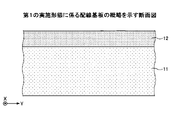
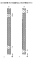
次に、配線基板の断面構造について説明する。図3は、第1の実施形態に係る配線基板の概略を示す断面図である。図4及び図5は、薄膜層の詳細を示す断面図である。図4は、図2中のI-I線に沿った断面図に相当し、図5は、図1中のII-II線に沿った断面図に相当する。 Next, the cross-sectional structure of the wiring board will be described. FIG. 3 is a cross-sectional view showing an outline of the wiring board according to the first embodiment. 4 and 5 are cross-sectional views showing details of the thin film layers. 4 corresponds to a cross-sectional view taken along line II in FIG. 2, and FIG. 5 corresponds to a cross-sectional view taken along line II-II in FIG.

図3に示すように、配線基板1は、ビルドアップ基板11と、ビルドアップ基板11の一方の面上に形成された薄膜層12とを有する。微細配線21は薄膜層12に形成されている。以下、ビルドアップ基板11の薄膜層12が形成された側を搭載側、その反対側を非搭載側ということがある。 As shown in FIG. 3 , the wiring board 1 has a buildup board 11 and a thin film layer 12 formed on one surface of the buildup board 11 . The fine wiring 21 is formed on the thin film layer 12 . Hereinafter, the side of the buildup substrate 11 on which the thin film layer 12 is formed is sometimes called the mounting side, and the opposite side is sometimes called the non-mounting side.

図4に示すように、薄膜層12は、ビルドアップ基板11上に形成された第3の絶縁層130と、第3の絶縁層130に形成された第1の微細配線層51とを有する。第1の微細配線層51はシード層121と金属めっき層122とを含む。例えば、シード層121は、チタン膜と、その上の銅膜とを有し、金属めっき層122は銅めっき層である。第1の微細配線層51は微細配線21A、デガスホール31A及びアンカービア用パッド32Aを有する。微細配線21Aは微細配線領域4A~4D内に形成され、デガスホール31A及びアンカービア用パッド32Aは接地領域7内に形成されている。微細配線21Aは微細配線21の一部である。微細配線21Aの上面は第3の絶縁層130の上面よりも下方に位置する。 As shown in FIG. 4 , the thin film layer 12 has a third insulating layer 130 formed on the buildup substrate 11 and a first fine wiring layer 51 formed on the third insulating layer 130 . The first fine wiring layer 51 includes a seed layer 121 and a metal plating layer 122 . For example, the seed layer 121 has a titanium film and a copper film thereon, and the metal plating layer 122 is a copper plating layer. The first fine wiring layer 51 has a fine wiring 21A, a degas hole 31A and an anchor via pad 32A. The fine wiring 21A is formed in the fine wiring regions 4A to 4D, and the degas hole 31A and the anchor via pad 32A are formed in the ground region . The fine wiring 21A is part of the fine wiring 21. FIG. The upper surface of the fine wiring 21A is located below the upper surface of the third insulating layer 130. As shown in FIG.

第3の絶縁層130には、複数の微細溝151と、デガスホール31Aの開口部となる凸部33Aを取り囲む溝251と、凸部33Aの内側のアンカービア用パッド32A用の溝351とが形成されている。微細配線21Aは複数の微細溝151内に形成され、アンカービア用パッド32Aは溝351内に形成されている。微細溝151は、微細配線21Aを含むL/Sパターンのライン部に形成されている。例えば、デガスホール31A及びアンカービア用パッド32Aの平面形状は円形である。金属めっき層122は金属層の一例であり、第3の絶縁層130の微細配線領域4A~4D内のパターンが第1のパターンの一例であり、第3の絶縁層130の接地領域7内のパターンが第2のパターンの一例である。微細配線21Aは配線の一例であり、微細溝151は第1の溝の一例であり、溝251は第2の溝の一例であり、溝351は第3の溝の一例である。 The third insulating layer 130 is formed with a plurality of fine grooves 151, grooves 251 surrounding the projections 33A serving as openings of the degas holes 31A, and grooves 351 for the anchor via pads 32A inside the projections 33A. It is The fine wirings 21 A are formed in a plurality of fine grooves 151 , and the anchor via pads 32 A are formed in the grooves 351 . The fine groove 151 is formed in the line portion of the L/S pattern including the fine wiring 21A. For example, the planar shape of the degas hole 31A and the anchor via pad 32A is circular. The metal plating layer 122 is an example of a metal layer, the patterns in the fine wiring regions 4A to 4D of the third insulating layer 130 are examples of the first pattern, and the patterns in the ground region 7 of the third insulating layer 130 are examples of the first pattern. A pattern is an example of a second pattern. The fine wire 21A is an example of a wire, the fine groove 151 is an example of a first groove, the groove 251 is an example of a second groove, and the groove 351 is an example of a third groove.

薄膜層12は、第3の絶縁層130上に形成された第4の絶縁層140と、第4の絶縁層140に形成された第2の微細配線層52とを有する。第2の微細配線層52はシード層131と金属めっき層132とを含む。例えば、シード層131は、チタン膜と、その上の銅膜とを有し、金属めっき層132は銅めっき層である。第2の微細配線層52は微細配線21B、デガスホール31B及びアンカービア用パッド32Bを有する(図2参照)。微細配線21Bは微細配線領域4A~4D内に形成され、デガスホール31B及びアンカービア用パッド32Bは接地領域7内に形成されている。微細配線21Bは微細配線21の一部である。微細配線21Bの上面は第4の絶縁層140の上面よりも下方に位置する。 The thin film layer 12 has a fourth insulating layer 140 formed on the third insulating layer 130 and a second fine wiring layer 52 formed on the fourth insulating layer 140 . The second fine wiring layer 52 includes a seed layer 131 and a metal plating layer 132 . For example, the seed layer 131 has a titanium film and a copper film thereon, and the metal plating layer 132 is a copper plating layer. The second fine wiring layer 52 has fine wirings 21B, degas holes 31B and anchor via pads 32B (see FIG. 2). The fine wiring 21B is formed in the fine wiring regions 4A to 4D, and the degas hole 31B and the anchor via pad 32B are formed in the ground region . The fine wiring 21B is a part of the fine wiring 21. FIG. The upper surface of the fine wiring 21B is located below the upper surface of the fourth insulating layer 140. As shown in FIG.

第4の絶縁層140には、複数の微細溝152と、デガスホール31Aの開口部となる凸部(図示せず)を取り囲む溝252と、凸部の内側のアンカービア用パッド32B用の溝(図示せず)とが形成されている。微細配線21Bは複数の微細溝152内に形成され、アンカービア用パッド32Bは凸部の内側のアンカービア用パッド32B用の溝内に形成されている。微細溝152は、微細配線21Bを含むL/Sパターンのライン部に形成されている。例えば、デガスホール31B及びアンカービア用パッド32Bの平面形状は円形である。金属めっき層132は金属層の一例であり、第4の絶縁層140の微細配線領域4A~4D内のパターンが第1のパターンの一例であり、第4の絶縁層140の接地領域7内のパターンが第2のパターンの一例である。微細配線21Aは配線の一例であり、微細溝151は第1の溝の一例であり、溝252は第2の溝の一例であり、アンカービア用パッド32B用の溝は第3の溝の一例である。 The fourth insulating layer 140 has a plurality of fine grooves 152, a groove 252 surrounding a projection (not shown) that serves as an opening of the degas hole 31A, and a groove (not shown) for the anchor via pad 32B inside the projection. (not shown) are formed. The fine wirings 21B are formed in a plurality of fine grooves 152, and the anchor via pads 32B are formed in the grooves for the anchor via pads 32B inside the projections. The fine groove 152 is formed in the line portion of the L/S pattern including the fine wiring 21B. For example, the planar shape of the degas hole 31B and the anchor via pad 32B is circular. The metal plating layer 132 is an example of a metal layer, the patterns in the fine wiring regions 4A to 4D of the fourth insulating layer 140 are examples of the first pattern, and the patterns in the ground region 7 of the fourth insulating layer 140 are examples of the first pattern. A pattern is an example of a second pattern. The fine wiring 21A is an example of a wiring, the fine groove 151 is an example of a first groove, the groove 252 is an example of a second groove, and the groove for the anchor via pad 32B is an example of a third groove. is.

薄膜層12は、ビルドアップ基板11上に形成された第5の絶縁層150と、第5の絶縁層150に形成された第3の微細配線層53とを有する。第3の微細配線層53はシード層141と金属めっき層142とを含む。例えば、シード層141は、チタン膜と、その上の銅膜とを有し、金属めっき層142は銅めっき層である。第3の微細配線層53は微細配線21C、デガスホール31C及びアンカービア用パッド32Cを有する。微細配線21Cは微細配線領域4A~4D内に形成され、デガスホール31C及びアンカービア用パッド32Cは接地領域7内に形成されている。微細配線21Cは微細配線21の一部である。微細配線21Cの上面は第5の絶縁層150の上面よりも下方に位置する。 The thin film layer 12 has a fifth insulating layer 150 formed on the buildup substrate 11 and a third fine wiring layer 53 formed on the fifth insulating layer 150 . A third fine wiring layer 53 includes a seed layer 141 and a metal plating layer 142 . For example, the seed layer 141 has a titanium film and a copper film thereon, and the metal plating layer 142 is a copper plating layer. The third fine wiring layer 53 has a fine wiring 21C, a degas hole 31C and an anchor via pad 32C. The fine wiring 21C is formed in the fine wiring regions 4A to 4D, and the degas hole 31C and the anchor via pad 32C are formed in the ground region . Fine wiring 21C is part of fine wiring 21 . The upper surface of the fine wiring 21C is located below the upper surface of the fifth insulating layer 150. As shown in FIG.

第4の絶縁層140には、複数の微細溝153と、デガスホール31Cの開口部となる凸部33Cを取り囲む溝253と、凸部33Cの内側のアンカービア用パッド32C用の溝353とが形成されている。微細配線21Cは複数の微細溝153内に形成され、アンカービア用パッド32Cは溝353内に形成されている。微細溝153は、微細配線21Cを含むL/Sパターンのライン部に形成されている。例えば、デガスホール31C及びアンカービア用パッド32Cの平面形状は円形である。金属めっき層142は金属層の一例であり、第5の絶縁層150の微細配線領域4A~4D内のパターンが第1のパターンの一例であり、第5の絶縁層150の接地領域7内のパターンが第2のパターンの一例である。微細配線21Cは配線の一例であり、微細溝153は第1の溝の一例であり、溝253は第2の溝の一例であり、溝353は第3の溝の一例である。 The fourth insulating layer 140 is formed with a plurality of fine grooves 153, grooves 253 surrounding the projections 33C serving as openings of the degas holes 31C, and grooves 353 for the anchor via pads 32C inside the projections 33C. It is The fine wires 21C are formed in a plurality of fine grooves 153, and the anchor via pads 32C are formed in the grooves 353. As shown in FIG. The fine groove 153 is formed in the line portion of the L/S pattern including the fine wiring 21C. For example, the planar shape of the degas hole 31C and the anchor via pad 32C is circular. The metal plating layer 142 is an example of a metal layer, the patterns in the fine wiring regions 4A to 4D of the fifth insulating layer 150 are examples of the first pattern, and the patterns in the ground region 7 of the fifth insulating layer 150 are examples of the first pattern. A pattern is an example of a second pattern. The fine wiring 21C is an example of wiring, the fine groove 153 is an example of a first groove, the groove 253 is an example of a second groove, and the groove 353 is an example of a third groove.

第5の絶縁層150にはマイクロビアホール150Aが形成されており、アンカービア用パッド32Cはマイクロビアホール150Aを通じて第2の微細配線層52に金属接合されている。また、第4の絶縁層140にはマイクロビアホール140Aが形成されており(図5参照)、アンカービア用パッド32Bは接地領域7内のマイクロビアホール140Aを通じて第1の微細配線層51に金属接合されている。従って、第1の微細配線層51、第2の微細配線層52及び第3の微細配線層53は、接地領域7内で互いに金属接合されている。従って、アンカー効果により強い接合強度が得られる。 A micro via hole 150A is formed in the fifth insulating layer 150, and the anchor via pad 32C is metal-bonded to the second fine wiring layer 52 through the micro via hole 150A. Further, a micro via hole 140A is formed in the fourth insulating layer 140 (see FIG. 5), and the anchor via pad 32B is metal-bonded to the first fine wiring layer 51 through the micro via hole 140A in the ground region 7. ing. Therefore, the first fine wiring layer 51 , the second fine wiring layer 52 and the third fine wiring layer 53 are metal-bonded to each other within the ground region 7 . Therefore, strong joint strength can be obtained by the anchor effect.

図5に示すように、薄膜層12は、第3の微細配線層53及び第5の絶縁層150上に、第3の微細配線層53の一部上にマイクロビアホール160Aが設けられた第6の絶縁層160を有する。薄膜層12は、更に、微細配線21の端部に接続され、第5の絶縁層150から突出する接続端子61、62及び63を有する。接続端子61は第1の微細配線層51の微細配線21Aに電気的に接続され、接続端子62は第2の微細配線層52の微細配線21Bに電気的に接続され、接続端子63は第3の微細配線層53の微細配線21Cに電気的に接続されている。接続端子61~63はシード層161と金属めっき層162とを含む。例えば、シード層161は、チタン膜と、その上の銅膜とを有し、金属めっき層162は銅めっき層である。 As shown in FIG. 5, the thin film layer 12 is formed on the third fine wiring layer 53 and the fifth insulating layer 150, and on a part of the third fine wiring layer 53, a sixth via hole 160A is provided. of insulation layer 160 . The thin film layer 12 further has connection terminals 61 , 62 and 63 that are connected to the ends of the fine wires 21 and protrude from the fifth insulating layer 150 . The connection terminal 61 is electrically connected to the fine wiring 21A of the first fine wiring layer 51, the connection terminal 62 is electrically connected to the fine wiring 21B of the second fine wiring layer 52, and the connection terminal 63 is electrically connected to the third wiring. is electrically connected to the fine wiring 21C of the fine wiring layer 53 of . The connection terminals 61-63 include a seed layer 161 and a metal plating layer 162. As shown in FIG. For example, the seed layer 161 has a titanium film and a copper film thereon, and the metal plating layer 162 is a copper plating layer.

配線基板1によれば、隣り合う微細配線21Aの間に微細溝151を分離する凸部が存在するため、隣り合う微細配線21Aの間でのイオンマイグレーションを抑制することができる。同様に、隣り合う微細配線21Bの間に微細溝152を分離する凸部が存在し、隣り合う微細配線21Cの間に微細溝153を分離する凸部が存在するため、隣り合う微細配線21Bの間でのイオンマイグレーション、隣り合う微細配線21Cの間でのイオンマイグレーションを抑制することができる。 According to the wiring board 1, since the protrusion separating the fine groove 151 exists between the adjacent fine wirings 21A, it is possible to suppress ion migration between the adjacent fine wirings 21A. Similarly, there is a protrusion separating the fine groove 152 between the adjacent fine wirings 21B, and a protrusion separating the fine groove 153 is present between the adjacent fine wirings 21C. Ion migration between adjacent fine wirings 21C can be suppressed.

また、デガスホール31A~31Cの内側に溝が形成されていないため、第3の絶縁層130、第4の絶縁層140、第5の絶縁層150にはボイドが発生しにくい。従って、薄膜層12内での剥がれを抑制し、剥がれに伴う接続不良を抑制することができる。 In addition, voids are less likely to occur in the third insulating layer 130, the fourth insulating layer 140, and the fifth insulating layer 150, since grooves are not formed inside the degas holes 31A to 31C. Therefore, it is possible to suppress the peeling in the thin film layer 12 and suppress the connection failure due to the peeling.

(第2の実施形態)
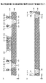
第2の実施形態について説明する。第2の実施形態は、配線基板の製造方法に関する。図6~図22は、第2の実施形態に係る配線基板の製造方法を示す断面図である。第2の実施形態では、まず、ビルドアップ基板11を形成し、その後に、ビルドアップ基板11上に薄膜層12を形成する。図6~図8は、ビルドアップ基板の形成方法を示す断面図である。図9~図22は、薄膜層の形成方法を示す断面図である。図9(a)~図22(a)には、図2中のI-I線に沿った断面図に相当する部分を示し、図9(b)~図22(b)には、図1中のII-II線に沿った断面図に相当する部分を示す。
(Second embodiment)
A second embodiment will be described. The second embodiment relates to a wiring board manufacturing method. 6 to 22 are cross-sectional views showing the method of manufacturing the wiring board according to the second embodiment. In the second embodiment, the buildup substrate 11 is formed first, and then the thin film layer 12 is formed on the buildup substrate 11 . 6 to 8 are cross-sectional views showing a method of forming a buildup board. 9 to 22 are cross-sectional views showing a method of forming thin film layers. 9(a) to 22(a) show a portion corresponding to a cross-sectional view taken along line II in FIG. 2, and FIGS. A portion corresponding to a cross-sectional view taken along line II-II in the figure is shown.

まず、図6(a)に示すように、支持体としてコア配線基板101を準備する。コア配線基板101はコア基板102及び第1の配線層104を備えている。コア基板102には厚さ方向に貫通するスルーホール103Aが形成されており、スルーホール103A内に貫通導体103が設けられている。例えば、スルーホール103Aはドリルやレーザを用いた加工等により形成することができ、貫通導体103及び第1の配線層104はめっき法及びフォトリソグラフィ等により形成することができる。なお、コア配線基板101としては、配線基板1が複数個取れる大判の基板が使用される。つまり、コア配線基板101は、配線基板1に対応する構造体が形成される複数の領域を有している。 First, as shown in FIG. 6A, a core wiring board 101 is prepared as a support. A core wiring board 101 includes a core board 102 and a first wiring layer 104 . A through hole 103A is formed through the core substrate 102 in the thickness direction, and a through conductor 103 is provided in the through hole 103A. For example, the through-hole 103A can be formed by processing using a drill or laser, and the through conductor 103 and the first wiring layer 104 can be formed by plating, photolithography, or the like. As the core wiring board 101, a large-sized board from which a plurality of wiring boards 1 can be obtained is used. That is, the core wiring board 101 has a plurality of regions in which structures corresponding to the wiring board 1 are formed.

次いで、図6(b)に示すように、コア基板102の両側に未硬化の樹脂フィルムを貼付し、加熱処理して硬化させることにより、第1の絶縁層105を形成する。第1の絶縁層105は、エポキシ樹脂又はポリイミド樹脂等の絶縁樹脂から形成される。液状樹脂を塗布することにより、第1の絶縁層105を形成してもよい。その後、コア基板102の両側の第1の絶縁層105をレーザで加工することにより、第1の配線層104の接続部に到達するビアホール106を第1の絶縁層105に形成する。 Next, as shown in FIG. 6B, uncured resin films are attached to both sides of the core substrate 102 and cured by heat treatment to form the first insulating layer 105 . The first insulating layer 105 is made of insulating resin such as epoxy resin or polyimide resin. The first insulating layer 105 may be formed by applying a liquid resin. After that, by processing the first insulating layer 105 on both sides of the core substrate 102 with a laser, a via hole 106 reaching the connecting portion of the first wiring layer 104 is formed in the first insulating layer 105 .

続いて、図7(a)に示すように、コア基板102の両側において、ビアホール106内のビア導体を介して第1の配線層104に接続される第2の配線層107を第1の絶縁層105上に形成する。第2の配線層107はセミアディティブ法によって形成することができる。 Subsequently, as shown in FIG. 7A, on both sides of the core substrate 102, the second wiring layer 107 connected to the first wiring layer 104 through the via conductors in the via holes 106 is subjected to the first insulation. It is formed on layer 105 . The second wiring layer 107 can be formed by a semi-additive method.

第2の配線層107の形成後、図7(b)に示すように、コア基板102の両側において、第1の絶縁層105上に、第2の配線層107の接続部上にビアホール109が設けられた第2の絶縁層108を形成する。第2の絶縁層108は、第1の絶縁層105と同様の方法で形成することができる。 After the formation of the second wiring layer 107, via holes 109 are formed on the first insulating layer 105 and on the connecting portion of the second wiring layer 107 on both sides of the core substrate 102, as shown in FIG. 7B. A provided second insulating layer 108 is formed. The second insulating layer 108 can be formed by a method similar to that of the first insulating layer 105 .

更に、同じく図7(b)に示すように、コア基板102の両側において、ビアホール109内のビア導体を介して第2の配線層107に接続される第3の配線層110を第2の絶縁層108上に形成する。第3の配線層110は、第2の配線層107と同様の方法に、セミアディティブ法によって形成することができる。但し、コア基板102の搭載側では、第2の絶縁層108上で第3の配線層110に配線パターンを形成せずに、第3の配線層110をべた状に形成することができる。 Further, as shown in FIG. 7B, on both sides of the core substrate 102, the third wiring layer 110 connected to the second wiring layer 107 through the via conductors in the via holes 109 is placed in the second insulation. Formed on layer 108 . The third wiring layer 110 can be formed by a semi-additive method in the same manner as the second wiring layer 107 . However, on the mounting side of the core substrate 102 , the third wiring layer 110 can be formed in a solid shape without forming a wiring pattern on the third wiring layer 110 on the second insulating layer 108 .

次いで、図8に示すように、コア基板102の非搭載側において、第2の絶縁層108上にソルダレジスト層111を形成する。その後、ソルダレジスト層111に第3の配線層110の接続部に達する開口部112を形成する。 Next, as shown in FIG. 8, a solder resist layer 111 is formed on the second insulating layer 108 on the non-mounting side of the core substrate 102 . After that, an opening 112 is formed in the solder resist layer 111 to reach the connecting portion of the third wiring layer 110 .

ソルダレジスト層111は、感光性のエポキシ樹脂又はアクリル樹脂等の絶縁樹脂から形成される。樹脂フィルムの貼り付け又は液状樹脂の塗布により、ソルダレジスト層111を形成してもよい。開口部112は、露光及び現像により形成することができる。ソルダレジスト層111に非感光性のエポキシ樹脂又はポリイミド樹脂等の絶縁樹脂を用いてもよい。この場合、開口部112は、レーザ加工又はブラスト処理により形成することができる。 The solder resist layer 111 is made of insulating resin such as photosensitive epoxy resin or acrylic resin. The solder resist layer 111 may be formed by attaching a resin film or applying a liquid resin. The opening 112 can be formed by exposure and development. An insulating resin such as a non-photosensitive epoxy resin or polyimide resin may be used for the solder resist layer 111 . In this case, the opening 112 can be formed by laser machining or blasting.

このようにして、ビルドアップ基板11を形成することができる。 Thus, the buildup substrate 11 can be formed.

次いで、図9(a)及び(b)に示すように、化学機械的研磨(chemical mechanical polishing)法によりビルドアップ基板11の搭載側の表面を研磨し、第2の絶縁層108を露出させる。 Next, as shown in FIGS. 9A and 9B, the mounting side surface of the buildup substrate 11 is polished by chemical mechanical polishing to expose the second insulating layer 108 .

その後、図10(a)及び(b)に示すように、第3の配線層110及び第2の絶縁層108上に第3の絶縁層130を形成する。第3の絶縁層130は、例えば感光性のエポキシ樹脂等の絶縁樹脂から形成される。 After that, as shown in FIGS. 10A and 10B, a third insulating layer 130 is formed on the third wiring layer 110 and the second insulating layer 108 . The third insulating layer 130 is made of insulating resin such as photosensitive epoxy resin.

続いて、図11(a)及び(b)に示すように、第3の絶縁層130上に第1の微細配線層51を形成する部分に開口部が設けられたフォトレジスト層191を形成する。フォトレジスト層191は第3の絶縁層130との界面近傍に括れ部191Aを有する。例えば、フォトレジスト層191は、微細配線21Aを形成する部分及びアンカービア用パッド32Aを形成する部分に開口部を有し、デガスホール31Aを形成する部分を覆う。 Subsequently, as shown in FIGS. 11A and 11B, a photoresist layer 191 is formed on the third insulating layer 130 so as to have openings at portions where the first fine wiring layers 51 are to be formed. . The photoresist layer 191 has a constricted portion 191A near the interface with the third insulating layer 130 . For example, the photoresist layer 191 has openings in the portion where the fine wiring 21A is formed and the portion where the anchor via pad 32A is formed, and covers the portion where the degas hole 31A is formed.

次いで、図12(a)及び(b)に示すように、フォトレジスト層191をマスクにして第3の絶縁層130をエッチングする。この結果、微細配線21Aを形成する領域を含むL/Sパターンのライン部において、第3の絶縁層130に微細溝151が形成される。また、アンカービア用パッド32Aを形成する領域等において、第3の絶縁層130に溝251が形成される。 Next, as shown in FIGS. 12A and 12B, the third insulating layer 130 is etched using the photoresist layer 191 as a mask. As a result, a fine groove 151 is formed in the third insulating layer 130 in the line portion of the L/S pattern including the region for forming the fine wiring 21A. Further, grooves 251 are formed in the third insulating layer 130 in areas where the anchor via pads 32A are to be formed.

その後、図13(a)及び(b)に示すように、スパッタ法により微細溝151及び溝251内にシード層121を形成する。シード層121はフォトレジスト層191の上面及び側面にも形成されるが、括れ部191A上には形成されない。シード層121の形成では、例えば、チタン膜及び銅膜を順次形成する。 After that, as shown in FIGS. 13A and 13B, a seed layer 121 is formed in the fine grooves 151 and 251 by sputtering. The seed layer 121 is also formed on the top and side surfaces of the photoresist layer 191, but not on the constricted portion 191A. In forming the seed layer 121, for example, a titanium film and a copper film are sequentially formed.

続いて、図14(a)及び(b)に示すように、フォトレジスト層191を、その上面及び側面に形成されたシード層121と共に除去する。 Subsequently, as shown in FIGS. 14A and 14B, the photoresist layer 191 is removed together with the seed layer 121 formed on its upper surface and side surfaces.

次いで、図15(a)及び(b)に示すように、無電解めっき法により、シード層121上に銅等からなる金属めっき層122を形成する。第1の微細配線層51に、微細配線21A、デガスホール31A及びアンカービア用パッド32Aが形成される。 Next, as shown in FIGS. 15A and 15B, a metal plating layer 122 made of copper or the like is formed on the seed layer 121 by electroless plating. A fine wire 21A, a degas hole 31A and an anchor via pad 32A are formed in the first fine wire layer 51. As shown in FIG.

その後、図16(a)及び(b)に示すように、第1の微細配線層51及び第3の絶縁層130上に、第1の微細配線層51の一部上にマイクロビアホール140Aが設けられた第4の絶縁層140を形成する。第4の絶縁層140は、例えば感光性のエポキシ樹脂等の絶縁樹脂から形成される。マイクロビアホール140Aは、例えばフォトリソグラフィ技術により形成する。 After that, as shown in FIGS. 16A and 16B, a micro via hole 140A is provided on the first fine wiring layer 51 and the third insulating layer 130 and on a part of the first fine wiring layer 51. A fourth insulating layer 140 is formed. The fourth insulating layer 140 is made of insulating resin such as photosensitive epoxy resin. The microvia hole 140A is formed by photolithography, for example.

続いて、図17(a)及び(b)に示すように、第4の絶縁層140上に第2の微細配線層52を形成する部分に開口部が設けられたフォトレジスト層192を形成する。フォトレジスト層192は第4の絶縁層140との界面近傍に括れ部192Aを有する。例えば、フォトレジスト層192は、微細配線21Bを形成する部分及びアンカービア用パッド32Bを形成する部分に開口部を有し、デガスホール31Bを形成する部分を覆う。 Subsequently, as shown in FIGS. 17A and 17B, a photoresist layer 192 is formed on the fourth insulating layer 140 so as to have openings at the portions where the second fine wiring layers 52 are to be formed. . The photoresist layer 192 has a constricted portion 192A near the interface with the fourth insulating layer 140 . For example, the photoresist layer 192 has openings in a portion for forming the fine wiring 21B and a portion for forming the anchor via pad 32B, and covers a portion for forming the degas hole 31B.

次いで、フォトレジスト層192をマスクにして第4の絶縁層140をエッチングする。この結果、微細配線21Bを形成する領域を含むL/Sパターンのライン部において、第4の絶縁層140に微細溝152が形成される。また、アンカービア用パッド32Bを形成する領域等において、第4の絶縁層140に溝252が形成される。 Then, using the photoresist layer 192 as a mask, the fourth insulating layer 140 is etched. As a result, a fine groove 152 is formed in the fourth insulating layer 140 in the line portion of the L/S pattern including the region for forming the fine wiring 21B. Further, grooves 252 are formed in the fourth insulating layer 140 in regions where the anchor via pads 32B are to be formed.

その後、図18(a)及び(b)に示すように、スパッタ法により微細溝152及び溝252内にシード層131を形成する。シード層131はフォトレジスト層192の上面及び側面にも形成されるが、括れ部192A上には形成されない。続いて、フォトレジスト層192を、その上面及び側面に形成されたシード層131と共に除去する。次いで、無電解めっき法により、シード層131上に銅等からなる金属めっき層132を形成する。第2の微細配線層52に、微細配線21B、デガスホール31B及びアンカービア用パッド32Bが形成される(図2参照)。 After that, as shown in FIGS. 18A and 18B, a seed layer 131 is formed in the fine grooves 152 and 252 by sputtering. The seed layer 131 is also formed on the top and side surfaces of the photoresist layer 192, but not on the constricted portion 192A. Subsequently, the photoresist layer 192 is removed together with the seed layer 131 formed on its top and side surfaces. Next, a metal plating layer 132 made of copper or the like is formed on the seed layer 131 by electroless plating. A fine wire 21B, a degas hole 31B and an anchor via pad 32B are formed in the second fine wire layer 52 (see FIG. 2).

続いて、図19(a)及び(b)に示すように、第2の微細配線層52及び第4の絶縁層140上に、第2の微細配線層52の一部上にマイクロビアホール150Aが設けられた第5の絶縁層150を形成する。第5の絶縁層150は、例えば感光性のエポキシ樹脂等の絶縁樹脂から形成される。マイクロビアホール150Aは、例えばフォトリソグラフィ技術により形成する。 Subsequently, as shown in FIGS. 19A and 19B, micro via holes 150A are formed on the second fine wiring layer 52 and the fourth insulating layer 140, and on part of the second fine wiring layer 52. A provided fifth insulating layer 150 is formed. The fifth insulating layer 150 is made of insulating resin such as photosensitive epoxy resin. The microvia hole 150A is formed by photolithography, for example.

次いで、図20(a)及び(b)に示すように、第5の絶縁層150上に第3の微細配線層53を形成する部分に開口部が設けられたフォトレジスト層193を形成する。フォトレジスト層193は第5の絶縁層150との界面近傍に括れ部193Aを有する。例えば、フォトレジスト層193は、微細配線21Cを形成する部分及びアンカービア用パッド32Cを形成する部分に開口部を有し、デガスホール31Cを形成する部分を覆う。 Next, as shown in FIGS. 20A and 20B, a photoresist layer 193 is formed on the fifth insulating layer 150 so that openings are provided at portions where the third fine wiring layer 53 is to be formed. The photoresist layer 193 has a constricted portion 193 A near the interface with the fifth insulating layer 150 . For example, the photoresist layer 193 has openings in a portion for forming the fine wiring 21C and a portion for forming the anchor via pad 32C, and covers a portion for forming the degas hole 31C.

その後、フォトレジスト層193をマスクにして第5の絶縁層150をエッチングする。この結果、微細配線21Cを形成する領域を含むL/Sパターンのライン部において、第5の絶縁層150に微細溝153が形成される。また、アンカービア用パッド32Cを形成する領域等において、第5の絶縁層150に溝253が形成される。 After that, the fifth insulating layer 150 is etched using the photoresist layer 193 as a mask. As a result, a fine groove 153 is formed in the fifth insulating layer 150 in the line portion of the L/S pattern including the region for forming the fine wiring 21C. In addition, grooves 253 are formed in the fifth insulating layer 150 in regions where the anchor via pads 32C are to be formed.

続いて、図21(a)及び(b)に示すように、スパッタ法により微細溝153及び溝253内にシード層141を形成する。シード層141はフォトレジスト層193の上面及び側面にも形成されるが、括れ部193A上には形成されない。次いで、フォトレジスト層193を、その上面及び側面に形成されたシード層141と共に除去する。その後、無電解めっき法により、シード層141上に銅等からなる金属めっき層142を形成する。第3の微細配線層53に、微細配線21C、デガスホール31C及びアンカービア用パッド32Cが形成される。 Subsequently, as shown in FIGS. 21A and 21B, a seed layer 141 is formed in the fine grooves 153 and 253 by sputtering. The seed layer 141 is also formed on the top and side surfaces of the photoresist layer 193, but not on the constricted portion 193A. The photoresist layer 193 is then removed together with the seed layer 141 formed on its top and side surfaces. Thereafter, a metal plating layer 142 made of copper or the like is formed on the seed layer 141 by electroless plating. A fine wire 21C, a degas hole 31C, and an anchor via pad 32C are formed in the third fine wire layer 53 .

続いて、図22(a)及び(b)に示すように、第3の微細配線層53及び第5の絶縁層150上に、第3の微細配線層53の一部上にマイクロビアホール160Aが設けられた第6の絶縁層160を形成する。第6の絶縁層160は、例えば感光性のエポキシ樹脂等の絶縁樹脂から形成される。マイクロビアホール160Aは、例えばフォトリソグラフィ技術により形成する。 Subsequently, as shown in FIGS. 22A and 22B, micro via holes 160A are formed on the third fine wiring layer 53 and the fifth insulating layer 150, and on part of the third fine wiring layer 53. A provided sixth insulating layer 160 is formed. The sixth insulating layer 160 is made of insulating resin such as photosensitive epoxy resin. The microvia hole 160A is formed by photolithography, for example.

次いで、マイクロビアホール160A内のビア導体を介して第3の微細配線層53に接続される接続端子61~63を形成する。接続端子61~63は、セミアディティブ法により形成することができ、シード層161と金属めっき層162とを含む。 Next, connection terminals 61 to 63 are formed to be connected to the third fine wiring layer 53 through via conductors in the micro via holes 160A. The connection terminals 61 - 63 can be formed by a semi-additive method and include a seed layer 161 and a metal plating layer 162 .

その後、図22(a)及び(b)に示す構造体を切断線(図示せず)に沿ってスライサー等により切断する。これにより、配線基板1に対応する構造体が個片化され、大判のコア配線基板101から第1の実施形態に係る配線基板1が複数得られる。このようにして、第1の実施形態に係る配線基板1を製造することができる。 After that, the structure shown in FIGS. 22A and 22B is cut by a slicer or the like along cutting lines (not shown). As a result, the structures corresponding to the wiring boards 1 are individualized, and a plurality of wiring boards 1 according to the first embodiment are obtained from the large-sized core wiring board 101 . Thus, the wiring board 1 according to the first embodiment can be manufactured.

この製造方法では、溝251内にシード層121及び金属めっき層122を形成することで、デガスホール31A及びアンカービア用パッド32Aを形成するため、ボイドの原因となる溝を形成せずとも第1の微細配線層51におけるイオンマイグレーションを抑制することができる。溝252内にシード層131及び金属めっき層132を形成することで、デガスホール31B及びアンカービア用パッド32Bを形成するため、ボイドの原因となる溝を形成せずとも第2の微細配線層52におけるイオンマイグレーションを抑制することができる。溝253内にシード層141及び金属めっき層142を形成することで、デガスホール31C及びアンカービア用パッド32Cを形成するため、ボイドの原因となる溝を形成せずとも第3の微細配線層53におけるイオンマイグレーションを抑制することができる。従って、ボイドに起因する剥がれ及び接続不良を抑制することができる。 In this manufacturing method, the degas holes 31A and the anchor via pads 32A are formed by forming the seed layer 121 and the metal plating layer 122 in the grooves 251. Therefore, the first method can be manufactured without forming grooves that cause voids. Ion migration in the fine wiring layer 51 can be suppressed. Since the degas holes 31B and the anchor via pads 32B are formed by forming the seed layer 131 and the metal plating layer 132 in the grooves 252, the second fine wiring layer 52 can be formed without forming grooves that cause voids. Ion migration can be suppressed. Since the degas holes 31C and the anchor via pads 32C are formed by forming the seed layer 141 and the metal plating layer 142 in the grooves 253, the third fine wiring layer 53 can be formed without forming grooves that cause voids. Ion migration can be suppressed. Therefore, it is possible to suppress peeling and poor connection caused by voids.

なお、図23(a)及び(b)に示すように、シード層121が微細溝151、溝251、溝351の底面上だけでなく、側面上に形成されることもある。この場合、図24(a)及び(b)に示すように、金属めっき層122の形成までの処理を行い、その後に、図25(a)及び(b)に示すように、シード層121のうちで金属めっき層122の上面より上方に位置する部分を除去することが好ましい。つまり、金属めっき層122の上面が第3の絶縁層130の上面よりも下方に位置するように処理することが好ましい。イオンマイグレーションをより確実に抑制するためである。シード層131及び141についても同様である。 As shown in FIGS. 23A and 23B, the seed layer 121 may be formed not only on the bottom surfaces of the fine grooves 151, 251, and 351, but also on the side surfaces. In this case, as shown in FIGS. 24(a) and 24(b), the process up to the formation of the metal plating layer 122 is performed, and then, as shown in FIGS. Of these, it is preferable to remove the portion located above the upper surface of the metal plating layer 122 . In other words, it is preferable to perform the treatment so that the upper surface of the metal plating layer 122 is located below the upper surface of the third insulating layer 130 . This is for more reliably suppressing ion migration. The same is true for seed layers 131 and 141 .

また、フォトレジスト層191の断面形状は特に限定されない。例えば、図26に示すように、フォトレジスト層191の断面形状が、第3の絶縁層130に近づくほど寸法が小さくなる逆テーパ形状を有していてもよい。この場合、微細溝151の側面がフォトレジスト層191の上面に隠れるため、微細溝151の側面上にシード層121が形成されにくくすることができる。また、図27に示すように、フォトレジスト層191の断面形状が、長方形状であってもよい。この場合、微細溝151を形成する際に、微細溝151の側面がフォトレジスト層191の上面に隠れるようなエッチング条件を選択することが好ましい。微細溝151の側面上にシード層121が形成された場合には、上述のように、金属めっき層122の形成後に、金属めっき層122の上面より上方に位置する部分を除去することが好ましい。フォトレジスト層192及び193についても同様である。 Moreover, the cross-sectional shape of the photoresist layer 191 is not particularly limited. For example, as shown in FIG. 26, the cross-sectional shape of the photoresist layer 191 may have an inverse tapered shape in which the dimensions become smaller as the third insulating layer 130 is approached. In this case, since the side surfaces of the fine groove 151 are hidden by the upper surface of the photoresist layer 191 , the seed layer 121 is less likely to be formed on the side surfaces of the fine groove 151 . Moreover, as shown in FIG. 27, the cross-sectional shape of the photoresist layer 191 may be rectangular. In this case, when forming the fine grooves 151 , it is preferable to select etching conditions such that the side surfaces of the fine grooves 151 are hidden by the upper surface of the photoresist layer 191 . When the seed layer 121 is formed on the side surface of the fine groove 151, it is preferable to remove the portion above the upper surface of the metal plating layer 122 after forming the metal plating layer 122, as described above. The same is true for photoresist layers 192 and 193 .

以上、好ましい実施の形態等について詳説したが、上述した実施の形態等に制限されることはなく、特許請求の範囲に記載された範囲を逸脱することなく、上述した実施の形態等に種々の変形及び置換を加えることができる。例えば、上述の実施形態ではビルドアップ基板が用いられているが、ビルドアップ基板に代えて支持基板が用いられてもよい。 Although the preferred embodiments and the like have been described in detail above, the present invention is not limited to the above-described embodiments and the like, and various modifications can be made to the above-described embodiments and the like without departing from the scope of the claims. Modifications and substitutions can be made. For example, although the buildup substrate is used in the above-described embodiments, a support substrate may be used instead of the buildup substrate.

1 配線基板
4A、4B、4C、4D 微細配線領域
7 接地領域
11 ビルドアップ基板
12 薄膜層
21、21A、21B、21C、21D 微細配線
31A、31B、31C デガスホール
32A、32B、32C アンカービア用パッド
33A、33C:凸部
51、52、53 微細配線層
61、62、63 接続端子
151、152、153 微細溝
251、252、253、351、353 溝
1 wiring board 4A, 4B, 4C, 4D fine wiring area 7 grounding area 11 build-up board 12 thin film layer 21, 21A, 21B, 21C, 21D fine wiring 31A, 31B, 31C degas hole 32A, 32B, 32C pad for anchor via 33A , 33C: Projections 51, 52, 53 Fine wiring layers 61, 62, 63 Connection terminals 151, 152, 153 Fine grooves 251, 252, 253, 351, 353 Grooves

Claims (9)

絶縁層に、互いに平行に延びる複数の第1の溝を含む第1のパターンと、凸部を取り囲む第2の溝を含む第2のパターンとを形成する工程と、
前記複数の第1の溝内と前記第2の溝内とに金属層を形成することにより、前記第1のパターン内に互いに平行に延びる複数の配線を形成し、前記第2のパターン内に前記凸部を開口部とするデガスホールを形成する工程と、
を有することを特徴とする配線基板の製造方法。
forming a first pattern including a plurality of first grooves extending parallel to each other and a second pattern including a second groove surrounding the protrusion in the insulating layer;
forming a plurality of wirings extending parallel to each other in the first pattern by forming a metal layer in the plurality of first trenches and in the second trenches; a step of forming a degas hole having the convex portion as an opening;
A method for manufacturing a wiring board, comprising:
前記複数の配線、ライン幅及びスペース幅が1μm~5μmのラインアンドスペースのパターンで形成することを特徴とする請求項1に記載の配線基板の製造方法。 2. The method of manufacturing a wiring board according to claim 1, wherein the plurality of wirings are formed in a line-and-space pattern having a line width and a space width of 1 μm to 5 μm . 前記金属層の上面を前記絶縁層の上面よりも下方に位置させることを特徴とする請求項1又は2に記載の配線基板の製造方法。 3. The method of manufacturing a wiring board according to claim 1, wherein the top surface of the metal layer is positioned below the top surface of the insulating layer. 前記デガスホールの平面形状は円形であることを特徴とする請求項1乃至3のいずれか1項に記載の配線基板の製造方法。 4. The method of manufacturing a wiring board according to claim 1, wherein the planar shape of the degas hole is circular. 前記第1のパターンと前記第2のパターンとを形成する工程において、前記凸部の内側に第3の溝を形成し、
前記複数の配線と前記デガスホールとを形成する工程において、前記第3の溝内にも前記金属層を形成することにより、前記第3の溝内にパッドを形成することを特徴とする請求項1乃至4のいずれか1項に記載の配線基板の製造方法。
In the step of forming the first pattern and the second pattern, forming a third groove inside the convex portion,
2. A pad is formed in said third groove by forming said metal layer also in said third groove in the step of forming said plurality of wirings and said degas hole. 5. The method for manufacturing a wiring board according to any one of items 1 to 4.
互いに平行に延びる複数の第1の溝を含む第1のパターンと、凸部を取り囲む第2の溝を含む第2のパターンとを含む絶縁層と、
前記複数の第1の溝内に形成された配線と、前記第2のパターン内に形成され、前記凸部を開口部とするデガスホールとを含む金属層と、
を有することを特徴とする配線基板。
an insulating layer including a first pattern including a plurality of first grooves extending parallel to each other and a second pattern including a second groove surrounding the protrusion;
a metal layer including wiring formed in the plurality of first grooves and degas holes formed in the second pattern and having openings corresponding to the protrusions;
A wiring board characterized by comprising:
前記複数の第1の溝内に形成された配線が、ライン幅及びスペース幅が1μm~5μmのラインアンドスペースのパターンで形成されていることを特徴とする請求項6に記載の配線基板。 7. The wiring board according to claim 6, wherein the wiring formed in the plurality of first grooves is formed in a line-and-space pattern with a line width and a space width of 1 μm to 5 μm . 前記金属層の上面は前記絶縁層の上面よりも下方に位置することを特徴とする請求項6又は7に記載の配線基板。 8. The wiring board according to claim 6, wherein the upper surface of the metal layer is positioned below the upper surface of the insulating layer. 前記複数の第1の溝内に形成された配線は、The wiring formed in the plurality of first grooves,
シード層と、 a seed layer;
前記シード層の上に形成された金属めっき層と、a metal plating layer formed on the seed layer;
を有し、has
前記シード層は、前記複数の第1の溝の底部と接触していることを特徴とする請求項6乃至8のいずれか1項に記載の配線基板。9. The wiring board according to claim 6, wherein the seed layer is in contact with bottoms of the plurality of first grooves.
JP2018248131A 2018-12-28 2018-12-28 Wiring board and its manufacturing method Active JP7145067B2 (en)

Priority Applications (2)

Application Number Priority Date Filing Date Title
JP2018248131A JP7145067B2 (en) 2018-12-28 2018-12-28 Wiring board and its manufacturing method
US16/714,905 US10743403B2 (en) 2018-12-28 2019-12-16 Wiring board

Applications Claiming Priority (1)

Application Number Priority Date Filing Date Title
JP2018248131A JP7145067B2 (en) 2018-12-28 2018-12-28 Wiring board and its manufacturing method

Publications (3)

Publication Number Publication Date
JP2020107845A JP2020107845A (en) 2020-07-09
JP2020107845A5 JP2020107845A5 (en) 2021-12-16
JP7145067B2 true JP7145067B2 (en) 2022-09-30

Family

ID=71123500

Family Applications (1)

Application Number Title Priority Date Filing Date
JP2018248131A Active JP7145067B2 (en) 2018-12-28 2018-12-28 Wiring board and its manufacturing method

Country Status (2)

Country Link
US (1) US10743403B2 (en)
JP (1) JP7145067B2 (en)

Families Citing this family (2)

* Cited by examiner, † Cited by third party
Publication number Priority date Publication date Assignee Title
KR20220001128A (en) * 2020-06-29 2022-01-05 삼성전자주식회사 Package substrate and semiconductor package including the same
CN111970816B (en) * 2020-08-27 2022-01-25 合肥鑫晟光电科技有限公司 Drive circuit backboard, manufacturing method thereof and backlight module

Citations (3)

* Cited by examiner, † Cited by third party
Publication number Priority date Publication date Assignee Title
JP2009272486A (en) 2008-05-08 2009-11-19 Nitto Denko Corp Method of manufacturing printed circuit board
JP2012156498A (en) 2011-01-07 2012-08-16 Fujikura Ltd Wiring board, mold, and manufacturing method of wiring board
US20160309574A1 (en) 2015-04-17 2016-10-20 Chung-Pao Wang Printed circuit board

Family Cites Families (1)

* Cited by examiner, † Cited by third party
Publication number Priority date Publication date Assignee Title
JP2016051834A (en) 2014-09-01 2016-04-11 イビデン株式会社 Printed wiring board and manufacturing method of the same

Patent Citations (3)

* Cited by examiner, † Cited by third party
Publication number Priority date Publication date Assignee Title
JP2009272486A (en) 2008-05-08 2009-11-19 Nitto Denko Corp Method of manufacturing printed circuit board
JP2012156498A (en) 2011-01-07 2012-08-16 Fujikura Ltd Wiring board, mold, and manufacturing method of wiring board
US20160309574A1 (en) 2015-04-17 2016-10-20 Chung-Pao Wang Printed circuit board

Also Published As

Publication number Publication date
US10743403B2 (en) 2020-08-11
JP2020107845A (en) 2020-07-09
US20200214122A1 (en) 2020-07-02

Similar Documents

Publication Publication Date Title
KR101103857B1 (en) Printed wiring board and method for manufacturing the same
US8389871B2 (en) Multilayered wiring board and method of manufacturing the same
TWI449480B (en) Multilayered wiring substrate
JP5547615B2 (en) WIRING BOARD, SEMICONDUCTOR DEVICE, AND WIRING BOARD MANUFACTURING METHOD
JP7145067B2 (en) Wiring board and its manufacturing method
JP6660850B2 (en) Electronic component built-in substrate, method of manufacturing the same, and electronic component device
JP7145068B2 (en) Wiring board and its manufacturing method
TWI451548B (en) Wiring substrate and manufacturing method thereof, and semiconductor device
CN105282969A (en) Printed circuit board and method of manufacturing the same
JP2001024023A (en) Semiconductor device
JP6505521B2 (en) WIRING BOARD, SEMICONDUCTOR DEVICE, AND WIRING BOARD MANUFACTURING METHOD
TWI590397B (en) Thermally enhanced semiconductor assembly with heat spreader and integrated dual build-up circuitries and method of making the same
JP7266469B2 (en) Wiring board manufacturing method and laminated structure
KR101501902B1 (en) Printed circuit board substrate having metal post and the method of manufacturing the same
JP2000022331A (en) Method for forming wiring pattern of build-up multilayer board
TWI778816B (en) Package structure with interconnection between chips and package method thereof
JP2020161641A (en) Multilayer substrate and manufacturing method thereof
JPH10284846A (en) Structure for mounting ball grid array packaging type semiconductor component
JP7266454B2 (en) Wiring board, laminated wiring board, and method for manufacturing wiring board
US20240030144A1 (en) Wiring substrate
KR102605701B1 (en) Semiconductor package and method for manufacturing the same
JP6891224B2 (en) Embedded parts package structure and its manufacturing method
JP2023137137A (en) Wiring board and manufacturing method of them
JP2024032660A (en) Printed circuit board and its manufacturing method
JP2017103350A (en) Printed-wiring board and method for manufacturing the same

Legal Events

Date Code Title Description
A521 Request for written amendment filed

Free format text: JAPANESE INTERMEDIATE CODE: A523

Effective date: 20211104

A621 Written request for application examination

Free format text: JAPANESE INTERMEDIATE CODE: A621

Effective date: 20211104

A977 Report on retrieval

Free format text: JAPANESE INTERMEDIATE CODE: A971007

Effective date: 20220826

TRDD Decision of grant or rejection written
A01 Written decision to grant a patent or to grant a registration (utility model)

Free format text: JAPANESE INTERMEDIATE CODE: A01

Effective date: 20220906

A61 First payment of annual fees (during grant procedure)

Free format text: JAPANESE INTERMEDIATE CODE: A61

Effective date: 20220916

R150 Certificate of patent or registration of utility model

Ref document number: 7145067

Country of ref document: JP

Free format text: JAPANESE INTERMEDIATE CODE: R150