JP7143902B2 - Chemiluminescence sulfur detector - Google Patents
Chemiluminescence sulfur detector Download PDFInfo
- Publication number
- JP7143902B2 JP7143902B2 JP2020570268A JP2020570268A JP7143902B2 JP 7143902 B2 JP7143902 B2 JP 7143902B2 JP 2020570268 A JP2020570268 A JP 2020570268A JP 2020570268 A JP2020570268 A JP 2020570268A JP 7143902 B2 JP7143902 B2 JP 7143902B2
- Authority
- JP
- Japan
- Prior art keywords
- pipe
- reaction cell
- heating furnace
- photomultiplier tube
- pressure
- Prior art date
- Legal status (The legal status is an assumption and is not a legal conclusion. Google has not performed a legal analysis and makes no representation as to the accuracy of the status listed.)
- Active
Links
Images


Classifications
-
- G—PHYSICS
- G01—MEASURING; TESTING
- G01N—INVESTIGATING OR ANALYSING MATERIALS BY DETERMINING THEIR CHEMICAL OR PHYSICAL PROPERTIES
- G01N21/00—Investigating or analysing materials by the use of optical means, i.e. using sub-millimetre waves, infrared, visible or ultraviolet light
- G01N21/75—Systems in which material is subjected to a chemical reaction, the progress or the result of the reaction being investigated
- G01N21/76—Chemiluminescence; Bioluminescence
Description
本発明は、化学発光硫黄検出器(Sulfur Chemiluminescence Detector)に関する。 The present invention relates to a Sulfur Chemiluminescence Detector.
化学発光硫黄検出器(SCD)は、化学発光を利用して試料中の硫黄化合物を高感度に検出可能な検出器であり、通常、ガスクロマトグラフ(GC)と組み合わせて使用される(例えば、特許文献1を参照)。 A sulfur chemiluminescence detector (SCD) is a detector that can detect sulfur compounds in a sample with high sensitivity using chemiluminescence, and is usually used in combination with a gas chromatograph (GC) (for example, patent See reference 1).
GCのカラムで分離された試料成分を含むガス(試料ガス)は、SCDに設けられた加熱炉に導入される。加熱炉は、燃焼管と該燃焼管を加熱するヒータとを備えており、試料ガスが前記燃焼管の内部を通過する過程で酸化され、該試料ガス中の硫黄化合物から二酸化硫黄(SO2)が生成される。更に、このSO2が前記燃焼管の内部を通過する過程で還元されてSO2から一酸化硫黄(SO)が生成される。このSOは、加熱炉の後段に設けられた反応セルに導入され、該反応セル内でオゾン(O3)と混合される。その結果、SOとO3の反応によって二酸化硫黄の励起種(SO2 *)が生成される。このSO2 *が化学発光を経て基底状態に戻る際の発光強度が、光検出器によって検出され、該発光強度から前記試料ガス中に含まれる硫黄化合物が定量される。A gas (sample gas) containing sample components separated by the GC column is introduced into a heating furnace provided in the SCD. The heating furnace includes a combustion tube and a heater for heating the combustion tube. The sample gas is oxidized while passing through the combustion tube, and sulfur dioxide (SO 2 ) is produced from sulfur compounds in the sample gas. is generated. Further, the SO2 is reduced while passing through the combustion tube to generate sulfur monoxide ( SO) from the SO2 . This SO is introduced into a reaction cell provided after the heating furnace and mixed with ozone (O 3 ) in the reaction cell. As a result , the reaction of SO and O3 produces an excited species of sulfur dioxide (SO2 * ) . The emission intensity when this SO 2 * returns to the ground state through chemiluminescence is detected by a photodetector, and the sulfur compounds contained in the sample gas are quantified from the emission intensity.
SCDは、メンテナンス作業の際などに、配管類が取り外されることがある。取り外した配管類はメンテナンス作業等の終了後に、元通り組み付けられるが、その際、配管の接続部の締め付けが不十分な箇所(以下、「接続不良箇所」とよぶ)が生じる場合がある。このような接続不良箇所に気付かずにSCDを起動させると、想定している性能が得られなかったり、部品が損傷したりするおそれがある。 The piping of the SCD may be removed during maintenance work or the like. After the maintenance work, etc., the removed pipes are reassembled as they were, but at that time, there may be places where the joints of the pipes are not sufficiently tightened (hereinafter referred to as "poor connection places"). If the SCD is started without noticing such a poor connection, the expected performance may not be obtained, or the parts may be damaged.
例えば、SCDの反応セルでの化学発光で生じた光は、光学フィルタを経て光電子増倍管に入射するが、この光の進路を構成する配管等に接続不良箇所があると、当該箇所から漏れ込んだ外光が光電子増倍管に入射し、光電子増倍管内に大電流が流れて破損するおそれがある。 For example, the light generated by chemiluminescence in the reaction cell of the SCD passes through an optical filter and enters the photomultiplier tube. A large amount of current flows in the photomultiplier tube, which may damage it.
また、SCDには、上記加熱炉の燃焼管から反応セルを経て真空ポンプに至るガスの流路があり、SCDの作動時には、真空ポンプによって該流路中のガスが吸引されている。こうしたガスの流路を構成する配管に接続不良箇所があると、当該箇所から外気が流路中に漏れ込んで加熱炉や反応セル内での反応が妨げられ、所望の性能が達成できなくなる場合がある。 The SCD also has a gas flow path from the combustion tube of the heating furnace to the reaction cell and to the vacuum pump. During operation of the SCD, the gas in the flow path is sucked by the vacuum pump. If there is a poor connection in the pipes that make up these gas flow paths, outside air leaks into the flow path from these points, hindering the reaction in the heating furnace or reaction cell, and the desired performance may not be achieved. There is
本発明は、上記の点に鑑みてなされたものであり、その目的とするところは、SCDに含まれる配管等に接続不良箇所があるか否かをユーザが容易に知ることができるようにすることにある。 SUMMARY OF THE INVENTION The present invention has been made in view of the above points, and an object of the present invention is to enable a user to easily know whether or not there is a poor connection in a pipe or the like included in an SCD. That's what it is.
上記課題を解決するために成された本発明の第1の態様に係る化学発光硫黄検出器(SCD)は、
加熱炉と、
前記加熱炉を通過したガスをオゾンと反応させる反応セルと、
前記反応セルからの光を検出する光電子増倍管と、
前記光電子増倍管に印加する駆動電圧を発生する電源と、
前記電源を制御するものであって、該電源の起動モードとして、試料分析に適用される第1の駆動電圧を発生させる通常モードと、前記第1の駆動電圧よりも低い第2の駆動電圧を発生させる異常検知モードとを有する電圧制御手段と、
前記電源を前記異常検知モードで起動させた際における、前記光電子増倍管の出力信号に基づいて、前記反応セルと前記光電子増倍管との間、又は前記反応セルと該反応セルに接続された1つ若しくは複数の配管のいずれかとの間に接続不良があるか否かを判定する判定手段と、
前記判定手段により前記接続不良があると判定された場合に、その旨をユーザに通知する通知手段と、
を有することを特徴としている。A sulfur chemiluminescence detector (SCD) according to a first aspect of the present invention, which has been made to solve the above problems,
a heating furnace;
a reaction cell for reacting the gas that has passed through the heating furnace with ozone;
a photomultiplier tube for detecting light from the reaction cell;
a power supply that generates a drive voltage to be applied to the photomultiplier tube;
and a normal mode for generating a first drive voltage applied to sample analysis, and a second drive voltage lower than the first drive voltage as activation modes of the power supply. a voltage control means having an anomaly detection mode to generate
connected between the reaction cell and the photomultiplier tube or between the reaction cells based on the output signal of the photomultiplier tube when the power supply is activated in the abnormality detection mode; Determination means for determining whether there is a connection failure between one or more pipes;
a notification means for notifying a user of the fact that the connection failure is determined by the determination means;
It is characterized by having
上記の通り、本発明の第1の態様に係る化学発光硫黄検出器では、光電子増倍管の出力信号に基づいて配管の接続不良の有無が判定される。光電子増倍管は、過大な光が入射すると内部に大電流が流れて破損するおそれがあるが、本発明の第1の態様に係る化学発光硫黄検出器は、これを防ぐために、光電子増倍管に印加する駆動電圧を試料の分析時よりも抑えた異常検知モードを有している。異常検知モードでは、光電子増倍管における電流増幅率が小さくなるため、過大な光が入射した場合でも光電子増倍管に大電流が流れるのを防止できる。そのため、上記本発明の第1の態様に係る化学発光硫黄検出器によれば、接続不良によって外光が漏れ込んでいる場合であっても光電子増倍管に損傷を与えることなく上記判定を行うことができる。 As described above, in the sulfur chemiluminescence detector according to the first aspect of the present invention, the presence or absence of poor connection of piping is determined based on the output signal of the photomultiplier tube. When an excessive amount of light is incident on the photomultiplier tube, a large current may flow inside the tube, causing damage. It has an anomaly detection mode in which the driving voltage applied to the tube is lower than that during sample analysis. In the abnormality detection mode, the current amplification factor of the photomultiplier tube is reduced, so even when excessive light is incident, a large current can be prevented from flowing through the photomultiplier tube. Therefore, according to the sulfur chemiluminescence detector according to the first aspect of the present invention, the determination can be performed without damaging the photomultiplier tube even when external light leaks due to poor connection. be able to.
なお、前記第1の電圧は500V以上とし、前記第2の電圧は500V未満とすることが望ましい。 It is preferable that the first voltage is 500V or more and the second voltage is less than 500V.
また、本発明の第1の態様に係るプログラムは、
加熱炉と、
前記加熱炉を通過したガスをオゾンと反応させる反応セルと、
前記反応セルからの光を検出する光電子増倍管と、
前記光電子増倍管に印加する駆動電圧を発生する電源と、
を有する化学発光硫黄検出器を制御するプログラムであって、
コンピュータを、
前記電源を制御するものであり、該電源の起動モードとして、試料分析に適用される第1の駆動電圧を発生させる通常モードと、前記第1の駆動電圧よりも低い第2の駆動電圧を発生させる異常検知モードとを有する電圧制御手段、
前記電源を前記異常検知モードで起動させた際における、前記光電子増倍管の出力信号に基づいて、前記反応セルと前記光電子増倍管との間、又は前記反応セルと該反応セルに接続された1つ若しくは複数の配管のいずれかとの間に接続不良があるか否かを判定する判定手段、及び
前記判定手段により前記接続不良があると判定された場合に、その旨をユーザに通知する通知手段、
として機能させることを特徴としている。Further, the program according to the first aspect of the present invention,
a heating furnace;
a reaction cell for reacting the gas that has passed through the heating furnace with ozone;
a photomultiplier tube for detecting light from the reaction cell;
a power supply that generates a drive voltage to be applied to the photomultiplier tube;
A program for controlling a sulfur chemiluminescence detector having
the computer,
It controls the power supply, and has a normal mode for generating a first driving voltage applied to sample analysis and a second driving voltage lower than the first driving voltage as activation modes of the power supply. Voltage control means having an anomaly detection mode that allows
connected between the reaction cell and the photomultiplier tube or between the reaction cells based on the output signal of the photomultiplier tube when the power supply is activated in the abnormality detection mode; determining means for determining whether or not there is a connection failure between one or more pipes, and notifying the user when the determination means determines that there is a connection failure notification means,
It is characterized by functioning as
また、上記課題を解決するために成された本発明の第2の態様に係る化学発光硫黄検出器は、
第1の配管及び該第1の配管を加熱する加熱手段を備えた加熱炉と、
前記加熱炉と第2の配管によって接続された反応セルと、
前記反応セルと第3の配管によって接続された真空ポンプと、
前記第1の配管にガスを導入する第4の配管と、
前記第2の配管、前記第3の配管、又は前記第4の配管の少なくともいずれかの内部における圧力を測定する圧力測定手段と、
前記真空ポンプを制御するポンプ制御手段と、
前記ポンプ制御手段によって前記真空ポンプを稼働させた状態における前記圧力測定手段の測定値に基づいて、前記第1の配管、前記反応セル、又は前記第1の配管若しくは前記反応セルに接続された複数の配管のいずれか、に接続不良箇所があるか否かを判定する判定手段と、
前記判定手段により前記接続不良箇所があると判定された場合にその旨をユーザに通知する通知手段と、
を有することを特徴としている。In addition, a chemiluminescence sulfur detector according to a second aspect of the present invention, which has been made to solve the above problems,
a heating furnace comprising a first pipe and heating means for heating the first pipe;
a reaction cell connected to the heating furnace by a second pipe;
a vacuum pump connected to the reaction cell by a third pipe;
a fourth pipe for introducing gas into the first pipe;
pressure measuring means for measuring the pressure in at least one of the second pipe, the third pipe, or the fourth pipe;
pump control means for controlling the vacuum pump;
the first pipe, the reaction cell, or a plurality of pressure sensors connected to the first pipe or the reaction cell based on the measured value of the pressure measurement means while the vacuum pump is operated by the pump control means; a determination means for determining whether or not there is a defective connection in any of the pipes;
notification means for notifying a user of the fact that the determination means determines that there is the poor connection location;
It is characterized by having
ここで、「前記第1の配管若しくは前記反応セルに接続された複数の配管」には、第1の配管若しくは反応セルに直接接続された配管(例えば前記第2の配管、前記第3の配管、及び第4の配管)だけでなく、他の配管を介して間接的に第1の配管若しくは反応セルに接続された配管も含まれる。 Here, "the first piping or a plurality of piping connected to the reaction cell" includes the first piping or piping directly connected to the reaction cell (for example, the second piping, the third piping , and fourth piping), but also piping indirectly connected to the first piping or the reaction cell via other piping.
化学発光硫黄検出器では、長時間稼動させると前記第1の配管の一部(後述する内部燃焼管)が変形して閉塞する場合があり、その場合は加熱炉から真空ポンプに至るガス流路において、加熱炉の上流側の領域と加熱炉の下流側の領域との圧力差が大きくなる。そこで、前記本発明の第2の態様に係る化学発光硫黄検出器は、更に、このような圧力差に基づいて前記第1の配管が閉塞しているか否かを判定するものとすることが望ましい。 In the chemiluminescence sulfur detector, if it is operated for a long time, part of the first pipe (internal combustion pipe described later) may be deformed and blocked.In that case, the gas flow path from the heating furnace to the vacuum pump , the pressure difference between the region on the upstream side of the heating furnace and the region on the downstream side of the heating furnace increases. Therefore, it is desirable that the sulfur chemiluminescence detector according to the second aspect of the present invention further determines whether or not the first pipe is clogged based on such a pressure difference. .
すなわち、前記本発明の第2の態様に係る化学発光硫黄検出器は、
前記圧力測定手段が、更に、前記第2の配管又は前記第3の配管の内部と、前記第4の配管の内部とにおける圧力の差を測定するものであって、
前記判定手段が、更に、前記差に基づいて前記第1の配管が閉塞しているか否かを判定するものであることが望ましい。That is, the chemiluminescent sulfur detector according to the second aspect of the present invention is
The pressure measuring means further measures the difference in pressure between the inside of the second pipe or the third pipe and the inside of the fourth pipe,
It is desirable that the determination means further determines whether or not the first pipe is blocked based on the difference.
また、本発明の第2の態様に係るプログラムは、
第1の配管及び該第1の配管を加熱する加熱手段を備えた加熱炉と、
前記加熱炉と第2の配管によって接続された反応セルと、
前記反応セルと第3の配管によって接続された真空ポンプと、
前記第1の配管にガスを導入する第4の配管と、
前記第2の配管、前記第3の配管、又は前記第4の配管の少なくともいずれかの内部における圧力を測定する圧力測定手段と、
前記真空ポンプを制御するポンプ制御手段と、
を有する化学発光硫黄検出器を制御するプログラムであって、
コンピュータを、
前記ポンプ制御手段によって前記真空ポンプを稼働させた状態における前記圧力測定手段の測定値に基づいて、前記第1の配管、前記反応セル、又は前記第1の配管若しくは前記反応セルに接続された複数の配管のいずれか、に接続不良箇所があるか否かを判定する判定手段、及び
前記判定手段により前記接続不良箇所があると判定された場合にその旨をユーザに通知する通知手段、
として機能させることを特徴としている。Further, the program according to the second aspect of the present invention,
a heating furnace comprising a first pipe and heating means for heating the first pipe;
a reaction cell connected to the heating furnace by a second pipe;
a vacuum pump connected to the reaction cell by a third pipe;
a fourth pipe for introducing gas into the first pipe;
pressure measuring means for measuring the pressure in at least one of the second pipe, the third pipe, or the fourth pipe;
pump control means for controlling the vacuum pump;
A program for controlling a sulfur chemiluminescence detector having
the computer,
the first pipe, the reaction cell, or a plurality of pressure sensors connected to the first pipe or the reaction cell based on the measured value of the pressure measurement means while the vacuum pump is operated by the pump control means; determination means for determining whether or not there is a poor connection in any of the pipes, and notification means for notifying the user when the determination means determines that there is a poor connection,
It is characterized by functioning as
以上の通り、本発明に係る化学発光硫黄検出器によれば、光電子増倍管からの出力信号又は圧力測定手段の測定値に基づいて、配管等の接続不良の有無が自動的に判定される。これにより、配管等に接続不良があるか否かをユーザが容易に知ることができるため、当該接続不良に気づかずに化学発光硫黄検出器を通常起動させてしまい、部品を損傷させたり、所望の性能が得られなかったりするのを防ぐことができる。 As described above, according to the chemiluminescence sulfur detector according to the present invention, the presence or absence of poor connection of piping or the like is automatically determined based on the output signal from the photomultiplier tube or the measured value of the pressure measuring means. . As a result, the user can easily know whether or not there is a poor connection in the piping or the like, so the sulfur chemiluminescence detector may be normally activated without noticing the poor connection, which may damage the parts or cause the desired damage. It is possible to prevent the performance from not being obtained.
以下、本発明を実施するための構成について図面を参照しつつ説明する。図1は、本実施形態による化学発光硫黄検出器(SCD)を備えたガスクロマトグラフシステム(GCシステム)の外観を示す正面図である。図2は、本実施形態によるSCDの要部構成を示す図である。図3及び図4は、前記GCシステムの内部構造を示す模式図であり、図3は正面図、図4は上面図である。図5は、前記SCDの加熱炉付近の構成を示す断面図である。 Hereinafter, a configuration for carrying out the present invention will be described with reference to the drawings. FIG. 1 is a front view showing the appearance of a gas chromatograph system (GC system) equipped with a sulfur chemiluminescence detector (SCD) according to this embodiment. FIG. 2 is a diagram showing the main configuration of the SCD according to this embodiment. 3 and 4 are schematic diagrams showing the internal structure of the GC system, wherein FIG. 3 is a front view and FIG. 4 is a top view. FIG. 5 is a cross-sectional view showing the configuration around the heating furnace of the SCD.
GC100は、試料導入部110と、カラム140を収容して加熱するカラムオーブン120と、制御基板(図示略)等が収容された制御基板収容部130とを備えている。カラムオーブン120の前面は開閉可能な扉121となっており、制御基板収容部130の前面にはタッチパネル132及び操作ボタン133を備えた操作パネル131が設けられている。
The
GC100では、試料導入部110においてキャリアガスの流れに試料が導入され、該試料を含むキャリアガスが、カラムオーブン120に収容されたカラム140の入口端に導入される。前記試料は、カラム140を通過する過程で成分毎に分離され、分離された各試料成分を含むガス(以下「試料ガス」とよぶ)が順次カラム140の出口端から溶出する。
In the
SCD200は、図2に示すように、高温下で試料ガスを酸化還元反応させるための加熱炉210と、加熱炉210を通過したガスをオゾンと反応させる反応セル231と、反応セル231に接続され、反応セル231内での反応による化学発光を検出するための光電子増倍管233と、光電子増倍管233に印加する駆動電圧を発生する高圧電源291と、反応セル231に供給するオゾンを生成するオゾン発生器234と、反応セル231及び加熱炉210内を真空引きする真空ポンプ236と、反応セル231の排気からオゾンを除去するオゾンスクラバ235と、フローコントローラ237と、制御/処理部300と、これらを収容する筐体240(図1参照)とを備えている。なお、反応セル231とオゾンスクラバ235との間の配管281には真空計(以下「第1真空計238」とよぶ)が設けられている。また、後述する不活性ガス流路264上にも真空計(以下「第2真空計239」とよぶ)が設けられている。なお、これらの第1真空計238及び第2真空計239が本発明における「圧力測定手段」に相当する。更に、SCD200は、GC100との境界に配置されて、GC100とSCD200とを連結するためのインターフェース250を備えている。
As shown in FIG. 2, the
なお、本実施形態では、第2真空計239を絶対圧センサから成るものとし、第1真空計238を差圧センサから成るものとする。なお、差圧センサである第1真空計238は、自身が設けられた位置における圧力(すなわち反応セル231の下流における圧力)と第2真空計239が設けられた位置における圧力(すなわち加熱炉210の上流における圧力)との差を測定値として出力する。
In this embodiment, the
図3及び図4に示すように、SCD200において加熱炉210は、SCD200の筐体240の上部前側に収容されており、反応セル231及びその他の構成要素(図3及び図4では省略)は、筐体240内部の残りの空間(例えば加熱炉210の下方や後方)に収容されている。なお、SCD200の筐体240のうち、加熱炉210が収容されている空間の上面は取外し可能な天板241(図1参照)となっている。
As shown in FIGS. 3 and 4, in the
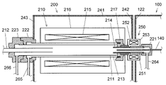
加熱炉210は、図5に示すように、外部燃焼管211と、内部燃焼管212と、酸化剤供給管213と、不活性ガス導入管214と、ヒータ215(本発明における「加熱手段」に相当)と、これらを収容するハウジング216とを備えている。なお、これらの外部燃焼管211、内部燃焼管212、酸化剤供給管213、及び不活性ガス導入管214が本発明における「第1の配管」に相当する。以下、図5に示された各管路、すなわち外部燃焼管211、内部燃焼管212、酸化剤供給管213、不活性ガス導入管214、及び配管251(後述)の、図中の左側に位置する端部を各管路の「左端」とよび、図中右側に位置する端部を各管路の「右端」とよぶ。
The
外部燃焼管211は、酸化剤供給管213の内部に、酸化剤供給管213と同軸に配置されており、不活性ガス導入管214は、その左端が外部燃焼管211の右端に挿入されている。また、内部燃焼管212は、その右端が外部燃焼管211の左端に挿入されている。なお、外部燃焼管211、内部燃焼管212、酸化剤供給管213、及び不活性ガス導入管214は、いずれもアルミナなどのセラミックで構成されている。
The
酸化剤供給管213及び外部燃焼管211の右端には、コネクタ217が取り付けられ、不活性ガス導入管214はこのコネクタ217に挿通されている。なお、酸化剤供給管213及び外部燃焼管211の右端の開口部はコネクタ217によって閉鎖されているが、コネクタ217の左端面には溝が切られており、該溝を介して酸化剤供給管213と外部燃焼管211の間で気体の流通が可能となっている。不活性ガス導入管214の右端は加熱炉210のハウジング216から突出しており、GC100とSCD200の境界に配置されたインターフェース250の内部に設けられた配管251の左端に接続されている。なお、インターフェース250は、配管251に加えて、これを加熱するためのヒータ252と、配管251及びヒータ252を収容するハウジング253を備えており、SCD200の筐体240の右側壁242に設けられた開口242a及びGC100の筐体の左側壁122に設けられた開口122aに挿通されている。配管251の右端はインターフェース250のハウジング253から突出しており、該右端には第1ジョイント221が取り付けられている。この第1ジョイント221には、不活性ガス導入管214に不活性ガス(ここでは窒素)を供給するための不活性ガス流路264(本発明における「第4の配管」に相当)が接続されている。なお、第1ジョイント221には、GC100のカラム140を挿通するための孔(図示略)が設けられている。カラム140の出口側の端部は、この孔から第1ジョイント221に挿通され、インターフェース250内の配管251を経て加熱炉210の内部、具体的には、不活性ガス導入管214の内部に差し込まれる。このとき、カラム140の出口端は、不活性ガス導入管214の左端よりも僅かに後退した位置に配置される。
A
一方、酸化剤供給管213、外部燃焼管211、及び内部燃焼管212の左端は、加熱炉210のハウジング216から突出し、更にSCD200の筐体240の左側壁243に設けられた開口243aから外部に突出している。筐体240の外部において、酸化剤供給管213の左端には、第2ジョイント222が取り付けられており、この第2ジョイント222には、酸化剤供給管213に酸化剤(ここでは酸素)を供給するための酸化剤流路265が接続されている。外部燃焼管211は、この第2ジョイント222に挿通されており、その左端には第3ジョイント223が取り付けられている。この第3ジョイント223には、外部燃焼管211に還元剤(ここでは水素)を供給するための還元剤流路266が接続されている。内部燃焼管212は、この第3ジョイント223に挿通されており、その左端は反応セル231に至る移送管270に接続されている。この移送管270が本発明における「第2の配管」に相当する。
On the other hand, the left ends of the
なお、移送管270は可撓性のチューブで構成されており、SCD200の筐体240の外部で折り返して筐体240の左側壁243に設けられた別の開口243b(図4参照)から再び筐体240の内部に進入し、筐体240内の反応セル231に接続されている。なお、図5では図示を省略しているが、SCD200の左側壁243の外面には、開口243a、243bを覆う位置に開閉可能なカバー271が設けられている。
The
不活性ガス流路264、酸化剤流路265、及び還元剤流路266は、いずれもフローコントローラ237に接続されており、このフローコントローラ237によって、不活性ガス供給源261、酸化剤供給源262、及び還元剤供給源263からそれぞれ不活性ガス流路264、酸化剤流路265、及び還元剤流路266に供給されるガスの流量が制御される。なお、不活性ガス供給源261、酸化剤供給源262、及び還元剤供給源263は、例えば、それぞれ窒素、酸素、及び水素を充填したガスボンベ等から成るものとすることができる。
The inert
不活性ガス供給源261からフローコントローラ237を経て不活性ガス流路264に供給された窒素は、第1ジョイント221、及び配管251を経て不活性ガス導入管214の右端に流入し、不活性ガス導入管214の内部を右端から左端に向かって進行する。なお、本実施例では不活性ガスとして窒素を使用するが、その他の不活性ガス(例えばヘリウム)を使用することも可能である。
Nitrogen supplied from the inert
酸化剤供給源262からフローコントローラ237を経て酸化剤流路265に供給された酸素は、第2ジョイント222を介して酸化剤供給管213の左端に流入し、酸化剤供給管213の内壁と外部燃焼管211の外壁との間の空間を右方に向かって進行する。酸化剤供給管213の右端に達した酸素は、コネクタ217の左端面に形成された溝(上述)から外部燃焼管211の内部に流入し、外部燃焼管211内を左方に向かって進行する。なお、本実施形態では、酸化剤として酸素を使用するものとするが、酸化剤として空気を使用することもできる。
Oxygen supplied from the
還元剤供給源263からフローコントローラ237を経て還元剤流路266に供給された水素は、第3ジョイント223を経て外部燃焼管211の左端に流入し、外部燃焼管211の内壁と内部燃焼管212の外壁との間の空間を右方に向かって進行する。内部燃焼管212の右端付近まで到達した水素は、そこから内部燃焼管212の中に引き込まれ、内部燃焼管212の内部を左方に向かって進行する。
Hydrogen supplied from the reducing
GC100のカラム140の出口端から加熱炉210の内部に導入された試料ガスは、外部燃焼管211の右端にて酸素と混合され、外部燃焼管211の内部を左に向かって進行しつつ、高温で酸化分解される。このとき、試料成分が硫黄化合物である場合には、二酸化硫黄が生成される。酸化分解された試料成分を含むガスは、外部燃焼管211の左端付近から導入される水素と共に内部燃焼管212に引き込まれる。前記酸化分解された試料成分に二酸化硫黄が含まれる場合は、ここで二酸化硫黄が水素と反応して一酸化硫黄に還元される。以上の酸化還元反応を促進するため、加熱炉210の内部は、ヒータ215によって500℃以上(望ましくは700℃~1200℃)に加熱される。内部燃焼管212を通過したガスは、移送管270を通じて反応セル231に導入される。
The sample gas introduced into the
なお、加熱炉210の内部において、カラム140の出口端の周囲には不活性ガス導入管214から窒素が供給される。この窒素は、カラム140の劣化による検出器汚染を防止する効果、及び加熱炉210内での酸化還元反応を促進する効果を有している。
Inside the
移送管270から反応セル231に送られたガスは、反応セル231内でオゾンと混合される。このとき、一酸化硫黄とオゾンの反応によって生じる化学発光が光学フィルタ232を介して光電子増倍管233で検出される。なお、前記オゾンは、酸化剤供給源262から酸素流路267を経て供給される酸素を用いてオゾン発生器234で生成され、配管268を経て反応セル231に供給される。このとき、酸素流路267を経てオゾン発生器234に供給される酸素の流量もフローコントローラ237によって制御される。反応セル231の下流には、オゾンスクラバ235と真空ポンプ236が設けられており、真空ポンプ236によって吸引された反応セル231内のガスは、オゾンスクラバ235によってオゾンを除去された上で、排気として外部に排出される。なお、反応セル231とオゾンスクラバ235の間の配管281、及びオゾンスクラバ235と真空ポンプ236の間の配管282が本発明における「第3の配管」に相当する。更に、本実施形態における移送管270、配管268、及び配管281が、本発明における「反応セルに接続された1つ若しくは複数の配管」に相当する。また、本実施形態における不活性ガス流路264、酸化剤流路265、還元剤流路266、酸素流路267、配管268、移送管270、配管281、配管282、配管251、及びカラム140が、本発明における「前記第1の配管若しくは前記反応セルに接続された複数の配管」に相当する。
The gas sent from the
光電子増倍管233からの出力信号は制御/処理部300に送られ、制御/処理部300にて該出力信号に基づいて試料ガス中の硫黄化合物の濃度が求められる。
The output signal from the
制御/処理部300の実体は、CPU、ROM、RAM、及び外部周辺機器などと通信するための入出力回路などを備えたマイクロコンピュータであり、例えばROMに格納された制御プログラムや制御用パラメータに従った演算処理を、CPUを中心に実行することによって、前記出力信号の処理や、各部の動作制御、具体的には、加熱炉210のヒータ215、インターフェース250のヒータ252、高圧電源291、オゾン発生器234、真空ポンプ236、及びフローコントローラ237等の制御が行われる。また、制御/処理部300には、ユーザの指示を入力するためのキーボード、マウス、タッチパネル、又は操作ボタンなどから成る入力装置320と、モニタ又はスピーカーなどから成る出力装置330が接続されている。
The substance of the control/
なお、図2では、制御/処理部300に係るように電圧制御部311、ポンプ制御部312、判定部313、及び通知部314が示されている。これらは、本実施形態に係るSCDの特徴的な動作を実現するための機能手段であり、いずれも制御/処理部300に搭載されたプログラムを制御/処理部のCPUが実行することによりソフトウェア的に実現される。電圧制御部311は、光電子増倍管に印加する駆動電圧を発生させる高圧電源291を制御するものであり、制御モードとして、試料分析に適用される第1の駆動電圧(例えば850V)を発生させる通常モードと、前記第1の駆動電圧よりも低い第2の駆動電圧(例えば460V)を発生させる異常検知モードとを有している。
Note that FIG. 2 shows a
以下、上記の機能手段によって実現される配管接続チェックの手順について図6のフローチャートを参照しつつ説明を行う。 The procedure for checking the pipe connection realized by the above functional means will be described below with reference to the flow chart of FIG.
まず、ユーザがSCDの電源を落としてメンテナンス作業等を行った後、入力装置320から制御/処理部300へ配管接続チェックの実行指示を入力する。この指示が、制御/処理部300に入力されると(ステップ11)、まず、電圧制御部311の制御の下に高圧電源291が異常検知モードで起動させる(ステップ12)。これにより、光電子増倍管233は、試料分析時に印加される電圧(第1の駆動電圧)よりも低い電圧(第2の駆動電圧)が印加された状態となる。続いて、このときの光電子増倍管233の出力信号が制御/処理部300に入力され、判定部313にて該出力信号が予め定められた閾値以上であるか否かが判定される(ステップ13)。ここで、前記出力信号が閾値以上であると判定された場合(ステップ13でYes)、すなわち光電子増倍管233で検出された光量が予め定められた値以上であると判定された場合には、通知部314が、出力装置330を制御して、光電子増倍管233と反応セル231との間、又は反応セル231と移送管270、配管268、若しくは配管281との間に接続不良がある旨をユーザに通知する(ステップ14)。このときの通知方法としては、例えば、前記接続不良を知らせる文字列をモニタに表示させたり、該接続不良を知らせる音声をスピーカーから発生させたりすることが考えられる。
First, the user turns off the power of the SCD and performs maintenance work, etc., and then inputs an instruction to execute a pipe connection check from the
ステップ13で光電子増倍管233の出力信号が閾値未満であると判定された場合(すなわち同ステップでNo)、及び上記ステップ13で光電子増倍管233の出力信号が閾値以上であると判定され(すなわち同ステップでYes)、上記ユーザへの通知(ステップ14)を行った後には、ポンプ制御部312によって真空ポンプ236が起動される(ステップ15)。これにより、反応セル231や、加熱炉210に設けられた各種配管(例えば、内部燃焼管212、外部燃焼管211、及び不活性ガス導入管214)内部の真空引きが開始される。その後、真空ポンプ236の起動から予め定められた時間が経過した時点(ステップ16でYes)で、第1真空計238及び第2真空計239の出力信号が判定部313に取り込まれ、各出力信号が、それぞれについて予め定められた閾値以上であるか否かが判定される。具体的には、まず第2真空計239で測定された絶対圧が予め定められた第1の閾値以上であるか否かが判定され(ステップ17)、続いて、第1真空計239で測定された差圧が予め定められた第2の閾値以上であるか否かが判定される(ステップ19)。ステップ17において前記絶対圧が前記第1の閾値以上であると判定された場合(ステップ17でYes)には、ガスの流路上に接続不良箇所があると考えられるため、通知部314が出力装置330を介してユーザにその旨を通知する(ステップ18)。また、ステップ19において前記差圧が前記第2の閾値以上であると判定された場合(ステップ19でYes)には、内部燃焼管212が閉塞していると考えられるため、通知部314が出力装置330を介してユーザにその旨を通知する(ステップ20)。なお、ステップ17とステップ19は逆の順番で実行してもよい。
If it is determined in step 13 that the output signal of the
以上、本発明を実施するための形態について具体例を挙げて説明を行ったが、本発明は上記実施形態に限定されるものではなく、本発明の趣旨の範囲で適宜変更が許容される。例えば、上記実施形態では、第1真空計238を差圧センサから成るものとし、第2真空計239を絶対圧センサから成るものとしたが、第1真空計238と第2真空計239の両方を絶対圧センサから成るものとし、第2真空計239の出力信号と第1真空計238の出力信号の差分をステップ19での判定に使用するものとしてもよい。また、上記実施例では、ステップ13で光電子増倍管233の出力信号が閾値以上であると判定されてステップ14でユーザへの通知を行った後に、ステップ15に進むものとしたが、ステップ14での通知を行った時点で一連のチェック動作を終了するものとしてもよい。
As mentioned above, although the form for implementing this invention was demonstrated with the specific example, this invention is not limited to the said embodiment, A change is permitted suitably within the scope of the meaning of this invention. For example, in the above embodiment, the
また、上記実施形態では、光電子増倍管233の出力に基づく配管接続不良のチェック及び通知(ステップ12~14)を行った後、真空計238、239の出力に基づく配管接続不良及び配管閉塞のチェック及び通知(ステップ15~20)を行うものとしたが、両者を逆の順序で実行したり、ユーザの指示に応じて両者のうちいずれか一方のみを実行したりするものとしてもよい。
Further, in the above-described embodiment, after performing check and notification (steps 12 to 14) of a pipe connection failure based on the output of the
また、上記実施形態では、電圧制御部311、ポンプ制御部312、判定部313、及び通知部314を実現するためのプログラムをSCDに内蔵されたマイクロコンピュータ(制御/処理部300)に搭載するものとしたが、上記プログラムは、SCD200に接続されたGC100内のマイクロコンピュータに搭載されるもの(図7)としてもよい。なお、PC400は、図7に示すように、GC100を介してSCD200に接続されたものであってもよく、図8に示すように、SCD200に直接接続されたものであってもよい。
Further, in the above embodiment, the program for realizing the
また、上記実施形態では、SCD200に設けられた入力装置320からユーザが配管接続等のチェック実行を指示し、配管に接続不良等があった場合は、SCD200に設けられた出力装置330を用いてユーザにその旨を通知するものとしたが、これに限らず、ユーザがGC100の操作パネル131に設けられたタッチパネル132若しくは操作ボタン133、又はPC400に接続されたキーボードやマウス等の入力装置520から前記チェックの実行指示を行ったり、GC100に設けられたスピーカー(図示略)若しくはタッチパネル132に含まれる液晶パネル等の表示装置、又はPC400に設けられた液晶ディスプレイやスピーカーなどの出力装置530によってユーザへの前記通知を行ったりするものとしてもよい。また、本発明に係るプログラムは、必ずしも単体のプログラムである必要はなく、例えば、SCD200を制御するためのプログラムや、GC100を制御するためのプログラムの一部に組み込まれたものであってもよい。
Further, in the above-described embodiment, the user instructs to check the piping connection or the like from the
また、上記実施形態では、横型の加熱炉(すなわち水平方向に延在する燃焼管を内蔵した加熱炉)を備えたSCDに本発明を適用する例を示したが、これに限らず、特許文献1に記載のような縦型の加熱炉(すなわち鉛直方向に延在する燃焼管を内蔵した加熱炉)を備えたSCDにも本発明を同様に適用することができる。 Further, in the above embodiment, an example in which the present invention is applied to an SCD equipped with a horizontal heating furnace (i.e., a heating furnace with a built-in combustion tube extending in the horizontal direction) was shown, but the invention is not limited to this. The present invention can be similarly applied to an SCD having a vertical heating furnace (that is, a heating furnace containing a combustion tube extending vertically) as described in 1 above.
100…ガスクロマトグラフ
200…化学発光硫黄検出器
210…加熱炉
211…外部燃焼管
212…内部燃焼管
213…酸化剤供給管
214…不活性ガス導入管
215…ヒータ
216…ハウジング
231…反応セル
233…光電子増倍管
291…高圧電源
234…オゾン発生器
235…オゾンスクラバ
236…真空ポンプ
238…第1真空計
239…第2真空計
268、281…配管
270…移送管
300…制御/処理部
311…電圧制御部
312…ポンプ制御部
313…判定部
314…通知部
400…パーソナルコンピュータDESCRIPTION OF
Claims (5)
前記加熱炉を通過したガスをオゾンと反応させる反応セルと、
前記反応セルからの光を検出する光電子増倍管と、
前記光電子増倍管に印加する駆動電圧を発生する電源と、
前記電源を制御するものであって、該電源の起動モードとして、試料分析に適用される第1の駆動電圧を発生させる通常モードと、前記第1の駆動電圧よりも低い第2の駆動電圧を発生させる異常検知モードとを有する電圧制御手段と、
前記電源を前記異常検知モードで起動させた際における、前記光電子増倍管の出力信号に基づいて、前記反応セルと前記光電子増倍管との間、又は前記反応セルと該反応セルに接続された1つ若しくは複数の配管のいずれかとの間に接続不良があるか否かを判定する判定手段と、
前記判定手段により前記接続不良があると判定された場合に、その旨をユーザに通知する通知手段と、
を有することを特徴とする化学発光硫黄検出器。 a heating furnace;
a reaction cell for reacting the gas that has passed through the heating furnace with ozone;
a photomultiplier tube for detecting light from the reaction cell;
a power supply that generates a drive voltage to be applied to the photomultiplier tube;
and a normal mode for generating a first drive voltage applied to sample analysis, and a second drive voltage lower than the first drive voltage as activation modes of the power supply. a voltage control means having an anomaly detection mode to generate
connected between the reaction cell and the photomultiplier tube or between the reaction cells based on the output signal of the photomultiplier tube when the power supply is activated in the abnormality detection mode; Determination means for determining whether there is a connection failure between one or more pipes;
a notification means for notifying a user of the fact that the connection failure is determined by the determination means;
A sulfur chemiluminescence detector comprising:
前記加熱炉を通過したガスをオゾンと反応させる反応セルと、
前記反応セルからの光を検出する光電子増倍管と、
前記光電子増倍管に印加する駆動電圧を発生する電源と、
を有する化学発光硫黄検出器を制御するプログラムであって、
コンピュータを、
前記電源を制御するものであり、該電源の起動モードとして、試料分析に適用される第1の駆動電圧を発生させる通常モードと、前記第1の駆動電圧よりも低い第2の駆動電圧を発生させる異常検知モードとを有する電圧制御手段、
前記電源を前記異常検知モードで起動させた際における、前記光電子増倍管の出力信号に基づいて、前記反応セルと前記光電子増倍管との間、又は前記反応セルと該反応セルに接続された1つ若しくは複数の配管のいずれかとの間に接続不良があるか否かを判定する判定手段、及び
前記判定手段により前記接続不良があると判定された場合に、その旨をユーザに通知する通知手段、
として機能させることを特徴とするプログラム。 a heating furnace;
a reaction cell for reacting the gas that has passed through the heating furnace with ozone;
a photomultiplier tube for detecting light from the reaction cell;
a power supply that generates a drive voltage to be applied to the photomultiplier tube;
A program for controlling a sulfur chemiluminescence detector having
the computer,
It controls the power supply, and has a normal mode for generating a first driving voltage applied to sample analysis and a second driving voltage lower than the first driving voltage as activation modes of the power supply. Voltage control means having an anomaly detection mode that allows
connected between the reaction cell and the photomultiplier tube or between the reaction cells based on the output signal of the photomultiplier tube when the power supply is activated in the abnormality detection mode; determining means for determining whether or not there is a connection failure between one or more pipes, and notifying the user when the determination means determines that there is a connection failure notification means,
A program characterized by functioning as
前記加熱炉と第2の配管によって接続された反応セルと、
前記反応セルと第3の配管によって接続された真空ポンプと、
前記第1の配管にガスを導入する第4の配管と、
前記第2の配管、前記第3の配管、又は前記第4の配管の少なくともいずれかの内部における圧力を測定する圧力測定手段と、
前記真空ポンプを制御するポンプ制御手段と、
前記ポンプ制御手段によって前記真空ポンプを稼働させた状態における前記圧力測定手段の測定値に基づいて、前記第1の配管、前記反応セル、又は前記第1の配管若しくは前記反応セルに接続された複数の配管のいずれか、に接続不良箇所があるか否かを判定する判定手段と、
前記判定手段により前記接続不良箇所があると判定された場合にその旨をユーザに通知する通知手段と、
を有しており、
前記圧力測定手段が、更に、前記第2の配管又は前記第3の配管の内部と、前記第4の配管の内部とにおける圧力の差を測定するものであり、
前記判定手段が、更に、前記差に基づいて前記第1の配管が閉塞しているか否かを判定するものである、化学発光硫黄検出器。 a heating furnace comprising a first pipe and heating means for heating the first pipe;
a reaction cell connected to the heating furnace by a second pipe;
a vacuum pump connected to the reaction cell by a third pipe;
a fourth pipe for introducing gas into the first pipe;
pressure measuring means for measuring the pressure in at least one of the second pipe, the third pipe, or the fourth pipe;
pump control means for controlling the vacuum pump;
the first pipe, the reaction cell, or a plurality of pressure sensors connected to the first pipe or the reaction cell based on the measured value of the pressure measurement means while the vacuum pump is operated by the pump control means; a determination means for determining whether or not there is a defective connection in any of the pipes;
notification means for notifying a user of the fact that the determination means determines that there is the poor connection location;
and
The pressure measuring means further measures the difference in pressure between the inside of the second pipe or the third pipe and the inside of the fourth pipe,
The sulfur chemiluminescence detector , wherein the determining means further determines whether or not the first pipe is clogged based on the difference .
前記加熱炉と第2の配管によって接続された反応セルと、
前記反応セルと第3の配管によって接続された真空ポンプと、
前記第1の配管にガスを導入する第4の配管と、
前記第2の配管、前記第3の配管、又は前記第4の配管の少なくともいずれかの内部における圧力を測定する圧力測定手段と、
前記真空ポンプを制御するポンプ制御手段と、
を有する化学発光硫黄検出器を制御するプログラムであって、
コンピュータを、
前記ポンプ制御手段によって前記真空ポンプを稼働させた状態における前記圧力測定手段の測定値に基づいて、前記第1の配管、前記反応セル、又は前記第1の配管若しくは前記反応セルに接続された複数の配管のいずれか、に接続不良箇所があるか否かを判定する判定手段、及び
前記判定手段により前記接続不良箇所があると判定された場合にその旨をユーザに通知する通知手段、
として機能させ、
前記圧力測定手段が、更に、前記第2の配管又は前記第3の配管の内部と、前記第4の配管の内部とにおける圧力の差を測定するものであり、
前記判定手段が、更に、前記差に基づいて前記第1の配管が閉塞しているか否かを判定するものである、プログラム。 a heating furnace comprising a first pipe and heating means for heating the first pipe;
a reaction cell connected to the heating furnace by a second pipe;
a vacuum pump connected to the reaction cell by a third pipe;
a fourth pipe for introducing gas into the first pipe;
pressure measuring means for measuring the pressure in at least one of the second pipe, the third pipe, or the fourth pipe;
pump control means for controlling the vacuum pump;
A program for controlling a sulfur chemiluminescence detector having
the computer,
the first pipe, the reaction cell, or a plurality of pressure sensors connected to the first pipe or the reaction cell based on the measured value of the pressure measurement means while the vacuum pump is operated by the pump control means; determination means for determining whether or not there is a poor connection in any of the pipes, and notification means for notifying the user when the determination means determines that there is a poor connection,
function as
The pressure measuring means further measures the difference in pressure between the inside of the second pipe or the third pipe and the inside of the fourth pipe,
The program , wherein the determination means further determines whether or not the first pipe is blocked based on the difference .
Applications Claiming Priority (1)
| Application Number | Priority Date | Filing Date | Title |
|---|---|---|---|
| PCT/JP2019/004269 WO2020161833A1 (en) | 2019-02-06 | 2019-02-06 | Sulfur chemiluminescence detector |
Publications (2)
| Publication Number | Publication Date |
|---|---|
| JPWO2020161833A1 JPWO2020161833A1 (en) | 2021-10-28 |
| JP7143902B2 true JP7143902B2 (en) | 2022-09-29 |
Family
ID=71947759
Family Applications (1)
| Application Number | Title | Priority Date | Filing Date |
|---|---|---|---|
| JP2020570268A Active JP7143902B2 (en) | 2019-02-06 | 2019-02-06 | Chemiluminescence sulfur detector |
Country Status (3)
| Country | Link |
|---|---|
| JP (1) | JP7143902B2 (en) |
| CN (1) | CN113056667A (en) |
| WO (1) | WO2020161833A1 (en) |
Families Citing this family (1)
| Publication number | Priority date | Publication date | Assignee | Title |
|---|---|---|---|---|
| CN116420073A (en) * | 2020-09-30 | 2023-07-11 | 株式会社堀场托卡德罗 | Total organic carbon meter and combustion reaction unit |
Citations (4)
| Publication number | Priority date | Publication date | Assignee | Title |
|---|---|---|---|---|
| JP2000357487A (en) | 1999-06-14 | 2000-12-26 | Shimadzu Corp | Mass-spectrometric device |
| JP2014227123A (en) | 2013-05-24 | 2014-12-08 | 株式会社デンソー | Abnormality diagnosis system |
| JP2015206604A (en) | 2014-04-17 | 2015-11-19 | 新日本無線株式会社 | Electrochemical measurement device |
| WO2018168599A1 (en) | 2017-03-15 | 2018-09-20 | 株式会社島津製作所 | Reaction device for chemiluminescence detector, chemiluminescence detector equipped with same, and chemiluminescence detection method |
Family Cites Families (8)
| Publication number | Priority date | Publication date | Assignee | Title |
|---|---|---|---|---|
| EP0502843A1 (en) * | 1988-11-25 | 1992-09-16 | BENNER, Richard L | Process and apparatus for the detection of sulfur |
| US6130095A (en) * | 1992-01-23 | 2000-10-10 | Sievers Instruments, Inc. | Method for the measurement of sulfur compounds |
| US5702954A (en) * | 1995-09-29 | 1997-12-30 | Colorado Seminary | Method to detect phosphorus |
| JP2000009644A (en) * | 1998-06-19 | 2000-01-14 | Hitachi Ltd | Fluorometer |
| CN201063436Y (en) * | 2007-04-28 | 2008-05-21 | 河南农大迅捷测试技术有限公司 | Protector for photomultiplier tube |
| JP5251729B2 (en) * | 2008-06-20 | 2013-07-31 | 株式会社島津製作所 | Spectrophotometer |
| CN101761780B (en) * | 2010-01-11 | 2012-12-26 | 中国石油大学(华东) | Gas pipeline leakage detecting and positioning device and method thereof |
| JP2015059876A (en) * | 2013-09-20 | 2015-03-30 | 株式会社島津製作所 | Oxidation device, chemiluminescence detector, and gas chromatograph |
-
2019
- 2019-02-06 CN CN201980076191.0A patent/CN113056667A/en active Pending
- 2019-02-06 JP JP2020570268A patent/JP7143902B2/en active Active
- 2019-02-06 WO PCT/JP2019/004269 patent/WO2020161833A1/en active Application Filing
Patent Citations (4)
| Publication number | Priority date | Publication date | Assignee | Title |
|---|---|---|---|---|
| JP2000357487A (en) | 1999-06-14 | 2000-12-26 | Shimadzu Corp | Mass-spectrometric device |
| JP2014227123A (en) | 2013-05-24 | 2014-12-08 | 株式会社デンソー | Abnormality diagnosis system |
| JP2015206604A (en) | 2014-04-17 | 2015-11-19 | 新日本無線株式会社 | Electrochemical measurement device |
| WO2018168599A1 (en) | 2017-03-15 | 2018-09-20 | 株式会社島津製作所 | Reaction device for chemiluminescence detector, chemiluminescence detector equipped with same, and chemiluminescence detection method |
Non-Patent Citations (1)
| Title |
|---|
| AGILENT TECHNOLOGIES,INC.,Agilent 8355 化学発光硫黄検出器 / Agilent 8255 化学発光窒素検出器 ユーザーマニュアル [オンライン],第3版,2015年12月,第35-60頁,[検索日 2019.02.25] インターネット: <URL:https://www.agilent.com/cs/library/usermanuals/public/Cop |
Also Published As
| Publication number | Publication date |
|---|---|
| WO2020161833A1 (en) | 2020-08-13 |
| CN113056667A (en) | 2021-06-29 |
| JPWO2020161833A1 (en) | 2021-10-28 |
Similar Documents
| Publication | Publication Date | Title |
|---|---|---|
| JP7099344B2 (en) | Chemiluminescent sulfur detector | |
| JP2020125922A5 (en) | ||
| JP5817738B2 (en) | Total organic carbon measuring device and method | |
| JP7143902B2 (en) | Chemiluminescence sulfur detector | |
| JP7400935B2 (en) | Component analysis system and component detection device | |
| JP5533641B2 (en) | Analysis equipment | |
| JP7070703B2 (en) | Gas chromatograph system | |
| JP7156406B2 (en) | Chemiluminescence sulfur detector | |
| EP1710569A1 (en) | Gas analyzer and method for controlling hydrogen flame ionization detector | |
| JP5708316B2 (en) | Analytical device with liquid crystal display with touch panel | |
| US20220026370A1 (en) | Sulfur chemiluminescence detector | |
| US20220214320A1 (en) | Instrument for elemental analysis | |
| JP2010127688A (en) | Leak detector | |
| JP2005129491A (en) | Fuel cell power generating system | |
| CN212845008U (en) | Methyl bromide concentration detection device | |
| CN210604500U (en) | Volatile organic gas detection system | |
| JP2007333543A (en) | Analyzer | |
| JP2020106278A (en) | Combustion type carbon analysis device and carbon analysis method | |
| JPS63315945A (en) | Instrument for measuring carbon content | |
| JP2020063998A (en) | Water analyzer and method for determining deterioration of ultraviolet lamp | |
| KR20020018477A (en) | Apparatus for controlling a fluid flow in semiconductor processing | |
| JPS63315946A (en) | Instrument for measuring carbon content |
Legal Events
| Date | Code | Title | Description |
|---|---|---|---|
| A521 | Request for written amendment filed |
Free format text: JAPANESE INTERMEDIATE CODE: A523 Effective date: 20210401 |
|
| A621 | Written request for application examination |
Free format text: JAPANESE INTERMEDIATE CODE: A621 Effective date: 20210401 |
|
| A131 | Notification of reasons for refusal |
Free format text: JAPANESE INTERMEDIATE CODE: A131 Effective date: 20220308 |
|
| A521 | Request for written amendment filed |
Free format text: JAPANESE INTERMEDIATE CODE: A523 Effective date: 20220428 |
|
| TRDD | Decision of grant or rejection written | ||
| A01 | Written decision to grant a patent or to grant a registration (utility model) |
Free format text: JAPANESE INTERMEDIATE CODE: A01 Effective date: 20220816 |
|
| A61 | First payment of annual fees (during grant procedure) |
Free format text: JAPANESE INTERMEDIATE CODE: A61 Effective date: 20220829 |
|
| R151 | Written notification of patent or utility model registration |
Ref document number: 7143902 Country of ref document: JP Free format text: JAPANESE INTERMEDIATE CODE: R151 |