JP7400935B2 - Component analysis system and component detection device - Google Patents
Component analysis system and component detection device Download PDFInfo
- Publication number
- JP7400935B2 JP7400935B2 JP2022206085A JP2022206085A JP7400935B2 JP 7400935 B2 JP7400935 B2 JP 7400935B2 JP 2022206085 A JP2022206085 A JP 2022206085A JP 2022206085 A JP2022206085 A JP 2022206085A JP 7400935 B2 JP7400935 B2 JP 7400935B2
- Authority
- JP
- Japan
- Prior art keywords
- reaction cell
- component
- furnace
- flow path
- redox
- Prior art date
- Legal status (The legal status is an assumption and is not a legal conclusion. Google has not performed a legal analysis and makes no representation as to the accuracy of the status listed.)
- Active
Links
Images


Classifications
-
- G—PHYSICS
- G01—MEASURING; TESTING
- G01N—INVESTIGATING OR ANALYSING MATERIALS BY DETERMINING THEIR CHEMICAL OR PHYSICAL PROPERTIES
- G01N21/00—Investigating or analysing materials by the use of optical means, i.e. using sub-millimetre waves, infrared, visible or ultraviolet light
- G01N21/75—Systems in which material is subjected to a chemical reaction, the progress or the result of the reaction being investigated
- G01N21/76—Chemiluminescence; Bioluminescence
- G01N21/766—Chemiluminescence; Bioluminescence of gases
-
- B—PERFORMING OPERATIONS; TRANSPORTING
- B01—PHYSICAL OR CHEMICAL PROCESSES OR APPARATUS IN GENERAL
- B01D—SEPARATION
- B01D53/00—Separation of gases or vapours; Recovering vapours of volatile solvents from gases; Chemical or biological purification of waste gases, e.g. engine exhaust gases, smoke, fumes, flue gases, aerosols
- B01D53/02—Separation of gases or vapours; Recovering vapours of volatile solvents from gases; Chemical or biological purification of waste gases, e.g. engine exhaust gases, smoke, fumes, flue gases, aerosols by adsorption, e.g. preparative gas chromatography
- B01D53/025—Separation of gases or vapours; Recovering vapours of volatile solvents from gases; Chemical or biological purification of waste gases, e.g. engine exhaust gases, smoke, fumes, flue gases, aerosols by adsorption, e.g. preparative gas chromatography with wetted adsorbents; Chromatography
-
- G—PHYSICS
- G01—MEASURING; TESTING
- G01N—INVESTIGATING OR ANALYSING MATERIALS BY DETERMINING THEIR CHEMICAL OR PHYSICAL PROPERTIES
- G01N30/00—Investigating or analysing materials by separation into components using adsorption, absorption or similar phenomena or using ion-exchange, e.g. chromatography or field flow fractionation
- G01N30/02—Column chromatography
- G01N30/04—Preparation or injection of sample to be analysed
- G01N30/06—Preparation
-
- G—PHYSICS
- G01—MEASURING; TESTING
- G01N—INVESTIGATING OR ANALYSING MATERIALS BY DETERMINING THEIR CHEMICAL OR PHYSICAL PROPERTIES
- G01N30/00—Investigating or analysing materials by separation into components using adsorption, absorption or similar phenomena or using ion-exchange, e.g. chromatography or field flow fractionation
- G01N30/02—Column chromatography
- G01N30/62—Detectors specially adapted therefor
- G01N30/74—Optical detectors
-
- Y—GENERAL TAGGING OF NEW TECHNOLOGICAL DEVELOPMENTS; GENERAL TAGGING OF CROSS-SECTIONAL TECHNOLOGIES SPANNING OVER SEVERAL SECTIONS OF THE IPC; TECHNICAL SUBJECTS COVERED BY FORMER USPC CROSS-REFERENCE ART COLLECTIONS [XRACs] AND DIGESTS
- Y02—TECHNOLOGIES OR APPLICATIONS FOR MITIGATION OR ADAPTATION AGAINST CLIMATE CHANGE
- Y02A—TECHNOLOGIES FOR ADAPTATION TO CLIMATE CHANGE
- Y02A50/00—TECHNOLOGIES FOR ADAPTATION TO CLIMATE CHANGE in human health protection, e.g. against extreme weather
- Y02A50/20—Air quality improvement or preservation, e.g. vehicle emission control or emission reduction by using catalytic converters
Landscapes
- Chemical & Material Sciences (AREA)
- Physics & Mathematics (AREA)
- Analytical Chemistry (AREA)
- General Physics & Mathematics (AREA)
- Pathology (AREA)
- Health & Medical Sciences (AREA)
- Biochemistry (AREA)
- General Health & Medical Sciences (AREA)
- Life Sciences & Earth Sciences (AREA)
- Immunology (AREA)
- Engineering & Computer Science (AREA)
- Chemical Kinetics & Catalysis (AREA)
- Spectroscopy & Molecular Physics (AREA)
- Plasma & Fusion (AREA)
- General Chemical & Material Sciences (AREA)
- Oil, Petroleum & Natural Gas (AREA)
- Investigating Or Analysing Materials By The Use Of Chemical Reactions (AREA)
- Investigating Or Analyzing Non-Biological Materials By The Use Of Chemical Means (AREA)
Description
本発明は、試料成分を検出する成分分析システムおよび成分検出装置に関する。 The present invention relates to a component analysis system and a component detection device for detecting sample components.
発光を伴う化学反応を利用して試料中の硫黄(S)成分を検出する化学発光硫黄検出器(SCD:Sulfur Chemiluminesence Detector)が知られている(例えば、特許文献1参照)。 A chemiluminescent sulfur detector (SCD) that detects a sulfur (S) component in a sample using a chemical reaction accompanied by luminescence is known (for example, see Patent Document 1).
特許文献1に記載されたSCDにおいては、ガスクロマトグラフの分離カラムにより分離された試料中の硫黄成分を含む気体が、酸化装置(酸化還元炉)により酸化されて還元される。これにより、試料中の硫黄成分から一酸化硫黄(SO)が生成される。生成された一酸化硫黄は、酸化装置から移送管を通して反応セルに導入される。
In the SCD described in
ここで、酸化装置は、ガスクロマトグラフのケーシングの上面上に取り付けられ、その上面から上方に向かって延びるように設けられている。一方、反応セルはガスクロマトグラフのケーシングの側方に設けられている。移送管は、140cm~200cm程度の長さを有し、酸化装置の上端部と反応セルとをつなぐように設けられている。 Here, the oxidizer is installed on the upper surface of the casing of the gas chromatograph and is provided so as to extend upward from the upper surface. On the other hand, the reaction cell is provided on the side of the casing of the gas chromatograph. The transfer pipe has a length of about 140 cm to 200 cm, and is provided to connect the upper end of the oxidizer and the reaction cell.
反応セルにおいては、一酸化硫黄とともにオゾン(O3)が導入され、一酸化硫黄とオゾンとが反応することにより、二酸化硫黄(SO2)の励起種が生成される。その二酸化硫黄が基底状態に遷移する際に発生する光が光検出器により検出される。検出された光の強度に基づいて、試料中の硫黄含有量が定量される。
本発明の目的は、試料成分を高い精度で検出することを可能にする成分分析システムおよび成分検出装置を提供することである。 An object of the present invention is to provide a component analysis system and a component detection device that make it possible to detect sample components with high accuracy.
本発明の第1の態様は、分離カラムを有するガスクロマトグラフと、成分検出装置とを備え、前記分離カラムは、複数の外面を有するカラムケーシング内に収容され、前記成分検出装置は、前記分離カラムにより分離された試料成分を含むガスが流れる第1の流路を有し、前記第1の流路を流れるガス中の試料成分を酸化および還元させる酸化還元炉と、前記還元された試料成分を含むガスの導入部を有し、前記導入部から導入される試料成分について発光を伴う化学反応を発生させる反応セルと、前記反応セルにおいて発生される光を検出する光検出器とを含み、前記第1の流路の下流端と前記反応セルの前記導入部とは、直接接続されるかまたは第2の流路を介して接続され、前記酸化還元炉および前記反応セルは、前記カラムケーシングの前記複数の外面のうちの一の外面に、ともに対向配置され、前記酸化還元炉は一方向に延びる長手形状を有し、前記酸化還元炉と前記反応セルとは前記酸化還元炉の長手方向に交差する方向に並び、前記酸化還元炉の長手方向に平行な方向において、前記反応セルは酸化還元炉の両端部の範囲内に位置する、成分分析システムに関する。 A first aspect of the present invention includes a gas chromatograph having a separation column and a component detection device, wherein the separation column is housed in a column casing having a plurality of outer surfaces, and the component detection device includes a gas chromatograph having a separation column. A oxidation-reduction furnace has a first flow path through which a gas containing sample components separated by is passed, and oxidizes and reduces the sample components in the gas flowing through the first flow path; a reaction cell that has an introduction section for a gas containing the gas, and that causes a chemical reaction accompanied by light emission with respect to a sample component introduced from the introduction section; and a photodetector that detects light generated in the reaction cell; The downstream end of the first flow path and the introduction part of the reaction cell are connected directly or through a second flow path, and the redox furnace and the reaction cell are connected to each other in the column casing. The redox furnace has a longitudinal shape extending in one direction, and the redox furnace and the reaction cell are arranged opposite to each other on one of the plurality of outside surfaces, and the redox furnace and the reaction cell are arranged in a longitudinal direction of the redox furnace. The reaction cells are arranged in transverse directions and in a direction parallel to the longitudinal direction of the redox furnace, the reaction cells are located within both ends of the redox furnace .
本発明の第2の態様は、分離カラムを有するガスクロマトグラフと、成分検出装置とを備え、前記分離カラムは、複数の外面を有するカラムケーシング内に収容され、前記成分検出装置は、前記分離カラムにより分離された試料成分を含むガスが流れる第1の流路を有し、前記第1の流路を流れるガス中の試料成分を酸化および還元させる酸化還元炉と、前記還元された試料成分を含むガスの導入部を有し、前記導入部から導入される試料成分について発光を伴う化学反応を発生させる反応セルと、前記反応セルにおいて発生される光を検出する光検出器とを含み、前記第1の流路の下流端と前記反応セルの前記導入部とは、直接接続されるかまたは第2の流路を介して接続され、前記酸化還元炉および前記反応セルは、前記カラムケーシングの前記複数の外面のうちの一の外面に、ともに対向配置され、前記酸化還元炉は、前記反応セルよりも上方に位置する、成分分析システムに関する。 A second aspect of the present invention includes a gas chromatograph having a separation column and a component detection device, wherein the separation column is housed in a column casing having a plurality of outer surfaces, and the component detection device includes a gas chromatograph having a separation column. A oxidation-reduction furnace has a first flow path through which a gas containing sample components separated by is passed, and oxidizes and reduces the sample components in the gas flowing through the first flow path; a reaction cell that has an introduction section for a gas containing the gas, and that causes a chemical reaction accompanied by light emission with respect to a sample component introduced from the introduction section; and a photodetector that detects light generated in the reaction cell; The downstream end of the first flow path and the introduction part of the reaction cell are connected directly or through a second flow path, and the redox furnace and the reaction cell are connected to each other in the column casing. The present invention relates to a component analysis system in which the oxidation-reduction furnace is located above the reaction cell, both of which are arranged facing each other on one of the plurality of outer surfaces.
本発明の第3の態様は、分離カラムを有するガスクロマトグラフとともに用いられる成分検出装置であって、前記分離カラムは、複数の外面を有するカラムケーシング内に収容され、前記分離カラムにより分離された試料成分を含むガスが流れる第1の流路を有し、前記第1の流路を流れるガス中の試料成分を酸化および還元させる酸化還元炉と、前記還元された試料成分を含むガスの導入部を有し、前記導入部から導入される試料成分について発光を伴う化学反応を発生させる反応セルと、前記反応セルにおいて発生される光を検出する光検出器とを備え、前記第1の流路の下流端と前記反応セルの前記導入部とは、直接接続されるかまたは第2の流路を介して接続され、前記酸化還元炉および前記反応セルは、前記カラムケーシングの前記複数の外面のうちの一の外面に、ともに対向配置され、前記酸化還元炉は一方向に延びる長手形状を有し、前記酸化還元炉と前記反応セルとは前記酸化還元炉の長手方向に交差する方向に並び、前記酸化還元炉の長手方向に平行な方向において、前記反応セルは酸化還元炉の両端部の範囲内に位置する、成分検出装置に関する。 A third aspect of the present invention is a component detection device used with a gas chromatograph having a separation column, wherein the separation column is housed in a column casing having a plurality of outer surfaces, and the sample separated by the separation column is A redox furnace having a first channel through which a gas containing a component flows, oxidizing and reducing a sample component in the gas flowing through the first channel, and an introduction section for the gas containing the reduced sample component. and a reaction cell that causes a chemical reaction accompanied by light emission with respect to the sample component introduced from the introduction part, and a photodetector that detects the light generated in the reaction cell, and the first flow path The downstream end of the column casing and the introduction part of the reaction cell are connected directly or via a second flow path, and the redox furnace and the reaction cell are The redox furnace has a longitudinal shape extending in one direction, and the redox furnace and the reaction cell are arranged in a direction intersecting the longitudinal direction of the redox furnace. , the reaction cell is located within a range of both ends of the redox furnace in a direction parallel to the longitudinal direction of the redox furnace.
本発明の第4の態様は、分離カラムを有するガスクロマトグラフとともに用いられる成分検出装置であって、前記分離カラムは、複数の外面を有するカラムケーシング内に収容され、前記分離カラムにより分離された試料成分を含むガスが流れる第1の流路を有し、前記第1の流路を流れるガス中の試料成分を酸化および還元させる酸化還元炉と、前記還元された試料成分を含むガスの導入部を有し、前記導入部から導入される試料成分について発光を伴う化学反応を発生させる反応セルと、前記反応セルにおいて発生される光を検出する光検出器とを備え、前記第1の流路の下流端と前記反応セルの前記導入部とは、直接接続されるかまたは第2の流路を介して接続され、前記酸化還元炉および前記反応セルは、前記カラムケーシングの前記複数の外面のうちの一の外面に、ともに対向配置され、前記酸化還元炉は、前記反応セルよりも上方に位置する、成分検出装置に関する。 A fourth aspect of the present invention is a component detection device used with a gas chromatograph having a separation column, wherein the separation column is housed in a column casing having a plurality of outer surfaces, and the sample separated by the separation column is A redox furnace having a first channel through which a gas containing a component flows, oxidizing and reducing a sample component in the gas flowing through the first channel, and an introduction section for the gas containing the reduced sample component. and a reaction cell that causes a chemical reaction accompanied by light emission with respect to the sample component introduced from the introduction part, and a photodetector that detects the light generated in the reaction cell, and the first flow path The downstream end of the column casing and the introduction part of the reaction cell are connected directly or via a second flow path, and the redox furnace and the reaction cell are A component detection device is disposed on the outer surface of one of the reactor cells to face each other, and the redox furnace is located above the reaction cell.
本発明によれば、試料成分を高い精度で検出することが可能になる。 According to the present invention, sample components can be detected with high accuracy.
SCDにおいては、試料中の硫黄成分が酸化および還元されることにより一酸化硫黄(SO)が生成される。ここで生成される一酸化硫黄は、化学的に不安定である。本発明者は、この点に着目し、酸化還元炉から反応セルに到達するまでの一酸化硫黄の変質についてシミュレーションを行った。その結果、生成された一酸化硫黄は、酸化還元炉から反応セルに至る流路(上記の移送管)を通過する時間(以下、移送時間と呼ぶ。)が長いほど、硫化水素(H2S)等の他の硫黄化合物へ変質することがわかった。 In SCD, sulfur monoxide (SO) is produced by oxidizing and reducing the sulfur component in the sample. The sulfur monoxide produced here is chemically unstable. The present inventor focused on this point and conducted a simulation of the deterioration of sulfur monoxide from the redox furnace to the reaction cell. As a result, the longer the time for the generated sulfur monoxide to pass through the flow path (the above-mentioned transfer pipe) from the redox furnace to the reaction cell (hereinafter referred to as transfer time), the more hydrogen sulfide (H 2 S ) and other sulfur compounds.
変質により得られる他の硫黄化合物は、反応セルに導入されてオゾン(O3)と反応しても、一酸化硫黄に比べて励起状態になりにくい。そのため、反応セルにおいて、一酸化硫黄以外の硫黄化合物は光の発生にほとんど寄与しない。これらのシミュレーションおよび検討の結果、本発明者は、酸化還元炉から反応セルに至るガスの移送時間を短くすることにより、より多くの一酸化硫黄を反応セルに導入することが可能となるという知見を得た。本発明者は、この知見から、特許文献1に記載された構成を有するSCDには、硫黄成分の検出精度を向上させる余地があることを見出した。
Other sulfur compounds obtained through alteration are less likely to become excited than sulfur monoxide even if they are introduced into a reaction cell and react with ozone (O 3 ). Therefore, in the reaction cell, sulfur compounds other than sulfur monoxide hardly contribute to the generation of light. As a result of these simulations and studies, the present inventor found that it is possible to introduce more sulfur monoxide into the reaction cell by shortening the gas transfer time from the redox furnace to the reaction cell. I got it. Based on this knowledge, the present inventor found that there is room for improving the detection accuracy of sulfur components in the SCD having the configuration described in
以下、実施の形態に係る成分分析システムおよび成分検出装置について図面を参照しつつ説明する。 Hereinafter, a component analysis system and a component detection device according to embodiments will be described with reference to the drawings.
[1]成分分析システムの基本構成
図1は実施の形態に係る成分分析システムの構成を示す図である。本実施の形態に係る成分分析システム1は、試料中の硫黄成分(硫黄化合物)を分析可能に構成され、ガスクロマトグラフ2および成分検出装置3を備える。
[1] Basic configuration of component analysis system FIG. 1 is a diagram showing the configuration of a component analysis system according to an embodiment. A
ガスクロマトグラフ2は、試料導入部10およびカラムオーブン11を含む。カラムオーブン11は、カラムケーシング11C内に分離カラム12および図示しない加熱装置が設けられた構成を有する。分離カラム12の上流端は試料導入部10に接続されている。分離カラム12の下流端は、カラムケーシング11Cの外部に引き出されている。試料導入部10は、いわゆる気化室であり、分離カラム12へ供給されるキャリアガスに硫黄成分および溶剤を含む試料を注入する。
本実施の形態に係る成分検出装置3は、化学発光硫黄検出器(SCD:Sulfur Chemiluminesence Detector)である。成分検出装置3は、酸化還元炉20、反応セル30、光検出器40、制御部50、フローコントローラ60、オゾン発生器70、スクラバ80およびポンプ90を含む。また、成分検出装置3は、これらの複数の構成要素を収容する検出装置ケーシング3Cを含む。
The
酸化還元炉20は、流路形成部材21および図示しない加熱装置を含む。流路形成部材21は、複数の管状部材により一方向に直線状に延びるように構成され、上流端21Uおよび下流端21Lを有する。流路形成部材21により形成されるガス流路が、第1の流路に相当する。流路形成部材21の上流端21Uは、分離カラム12の下流端に接続されている。酸化還元炉20においては、上流端21Uに硫黄成分を含む試料が導入されることにより、一酸化硫黄(SO)が生成される。酸化還元炉20において発生する化学反応の詳細は後述する。なお、酸化還元炉20は、図示しない断熱材により覆われた状態で検出装置ケーシング3C内に配置される。
The oxidation-
反応セル30は、第1の導入部31、第2の導入部32および導出部33を有する。第1の導入部31は、移送管TL0を介して流路形成部材21の下流端21Lに接続されている。移送管TL0により形成されるガス流路が、第2の流路に相当する。移送管TL0は、例えばフレキシブル性を有する樹脂配管により形成されている。
The
本実施の形態において、移送管TL0の長さは、酸化還元炉20において生成される一酸化硫黄が酸化還元炉20から反応セル30に到達するまでの間に許容される程度を超えて変質しないように定められ、例えば100cm以下である。移送管TL0の長さは、70cm以下であることが好ましく、55cm以下であることがより好ましい。また、移送管TL0の長さは、流路形成部材21の長さよりも短くなるように定められてもよい。
In the present embodiment, the length of the transfer pipe TL0 is such that the sulfur monoxide generated in the
なお、図1の例では、移送管TL0が検出装置ケーシング3Cの外部に位置するように設けられているが、移送管TL0は、少なくとも一部が検出装置ケーシング3Cの内部に位置するように設けられてもよい。さらに、本実施の形態においては、流路形成部材21の下流端21Lと反応セル30の第1の導入部31とが直接接続されてもよい。この場合、移送管TL0は不要となる。
In the example of FIG. 1, the transfer pipe TL0 is provided so as to be located outside the detection device casing 3C, but the transfer pipe TL0 is provided so that at least a portion thereof is located inside the
第2の導入部32は、移送管TL1を介してオゾン発生器70に接続されている。導出部33には、排気管ELが接続されている。排気管ELには、上流から下流に向かってスクラバ80およびポンプ90がこの順で設けられている。ポンプ90は、ガスクロマトグラフ2の分離カラム12において分離された試料成分を、排気管EL、反応セル30、移送管TL0および流路形成部材21を通してキャリアガスとともに吸引する。スクラバ80は、排気管ELを流れるガスからオゾンを除去する。
The
フローコントローラ60には、図示しない窒素供給源、酸素供給源および水素供給源から、窒素(N2)、酸素(O2)および水素(H2)が供給される。フローコントローラ60は、供給された窒素、酸素および水素を酸化還元炉20の互いに異なる部分に供給する。流路形成部材21においては、上流から下流に向かって窒素の供給部分、酸素の供給部分および水素の供給部分がこの順に並ぶ。以下の説明では、流路形成部材21における酸素の供給部分および水素の供給部分をそれぞれ酸化部22および還元部23と呼ぶ。
Nitrogen (N 2 ), oxygen (O 2 ), and hydrogen ( H 2 ) are supplied to the
フローコントローラ60は、さらに酸素供給源から供給された酸素をオゾン発生器70に供給する。この場合、オゾン発生器70は、供給された酸素からオゾン(O3)を生成し、生成されたオゾンを移送管TL1を通して反応セル30の第2の導入部32に供給する。
反応セル30に近接するように光検出器40が設けられている。反応セル30と光検出器40との間には、光学フィルタFが設けられている。光学フィルタFは、特定の波長領域の光を透過させ、他の波長領域の光を透過させない。本実施の形態において、特定の波長領域は、オゾンと一酸化硫黄とが反応することにより発生する光(二酸化硫黄が基底状態に遷移する際に発生する光)の波長を含むように定められる。
A
光検出器40は、例えば光電子倍増管(PMT:Photomultiplier Tube)であり、反応セル30で発生しかつ光学フィルタFを通過する光を検出する。また、光検出器40は、検出した光の光量に応じた検出信号を制御部50に与える。
The
制御部50は、例えばCPU(中央演算処理装置)およびメモリ、またはマイクロコンピュータからなり、成分検出装置3の各構成要素を制御する。制御部50は、さらに、光検出器40から与えられる検出信号に基づいてクロマトグラムを生成する。これにより、生成されたクロマトグラムを用いてガスクロマトグラフ2に注入された試料中の硫黄成分の濃度等を算出することが可能になる。
The
上記の成分検出装置3においては、ポンプ90が動作することにより、分離カラム12により分離された硫黄成分を含むキャリアガス(以下、対象ガスと呼ぶ。)が酸化還元炉20の流路形成部材21内に導入される。流路形成部材21に導入された対象ガスは、上流端21Uの近傍でフローコントローラ60から供給される窒素と混合されつつ酸化部22へ流れる。窒素は、対象ガスについての後述する酸化還元反応を促進するため、および成分検出装置3内のガス流路の汚染を低減するために用いられる。なお、酸化還元炉20には、窒素は供給されなくてもよい。あるいは、酸化還元炉20には、窒素に代えてアルゴン(Ar)等の他の不活性ガスが供給されてもよい。
In the
酸化部22においては、フローコントローラ60から供給される酸素により対象ガスの硫黄成分が高温(例えば約1000℃)で酸化される。それにより、二酸化硫黄(SO2)が生成される。二酸化硫黄を含む対象ガスは還元部23へ流れる。還元部23においては、フローコントローラ60から供給される水素により二酸化硫黄が高温(例えば約850℃)で還元される。それにより、不安定な一酸化硫黄(SO)が生成される。一酸化硫黄を含む対象ガスは、流路形成部材21の下流端21Lから移送管TL0を通して反応セル30の第1の導入部31へ流れる。
In the oxidizing
反応セル30においては、第1の導入部31から導入される対象ガスと、オゾン発生器70により第2の導入部32から導入されるオゾンとが混合される。そこで、一酸化硫黄とオゾンとの反応により、二酸化硫黄(SO2)の励起種が生成される。生成された二酸化硫黄は、基底状態に遷移する。この際に発生する光が、光学フィルタFを通して光検出器40により検出される。光検出器40から出力される検出信号に基づいて、ガスクロマトグラフ2に導入された試料についてのクロマトグラムが生成される。
In the
反応セル30内の雰囲気にはオゾンが含まれる。そこで、反応セル30内の雰囲気は、スクラバ80によりオゾンが除去されて無害化されつつ排気管ELを通して成分検出装置3の外部に排出される。
The atmosphere inside the
[2]酸化還元炉20から反応セル30に至るガス流路の長さ
上記のように、本実施の形態に係る成分検出装置3においては、酸化還元炉20の上流端21Uと反応セル30の第1の導入部31とが、100cm以下の長さを有する移送管TL0を介して接続されるかまたは直接接続される。
[2] Length of the gas flow path from the oxidation-
この構成によれば、成分検出装置3による試料の硫黄成分の検出時に、酸化還元炉20において発生される一酸化硫黄が比較的短時間で反応セル30に導入される。それにより、酸化還元炉20において生成される一酸化硫黄が、許容される程度を超えて変質することなく反応セル30に到達する。その結果、試料中の硫黄成分を高い精度で検出することが可能になる。本発明者は、この効果を確認するために、以下の試験および評価を行った。
According to this configuration, when the
本発明者は、酸化還元炉と反応セルとが55cmの長さを有する移送管で接続されたSCDを実施例に係るSCDとして用意した。一方、本発明者は、酸化還元炉と反応セルとが150cmの長さを有する移送管で接続されたSCDを比較例に係るSCDとして用意した。 The present inventor prepared an SCD in which a redox furnace and a reaction cell were connected by a transfer tube having a length of 55 cm as an SCD according to an example. On the other hand, the present inventor prepared an SCD in which a redox furnace and a reaction cell were connected by a transfer pipe having a length of 150 cm as an SCD according to a comparative example.
次に、本発明者は、同一の試料について硫黄成分の検出を、実施例および比較例に係るSCDを用いて10回ずつ繰り返し行った。各検出結果から以下の評価を行った。
Next, the present inventor repeatedly detected the sulfur component on the
まず、本発明者は、実施例および比較例に係るSCDの検出結果から、両者の絶対感度を比較した。図2は実施例および比較例に係るSCDの絶対感度の比較結果を示す図である。図2のグラフにおいては、縦軸が絶対感度を表し、横軸が検出回数を表す。また、図2では、丸印が実施例に対応し、×印が比較例に対応する。絶対感度は、各SCDによる硫黄成分の検出ごとに、各SCDにより生成されるクロマトグラムから試料中の硫黄成分に対応するピークを抽出し、そのピークの面積値を算出することにより求めた。図2のグラフによれば、実施例のSCDの絶対感度は、1回目から10回目までの全ての回において比較例のSCDの絶対感度よりも高い。 First, the present inventors compared the absolute sensitivities of both Examples and Comparative Examples based on the detection results of SCDs. FIG. 2 is a diagram showing comparison results of absolute sensitivities of SCDs according to Examples and Comparative Examples. In the graph of FIG. 2, the vertical axis represents the absolute sensitivity, and the horizontal axis represents the number of detections. Further, in FIG. 2, circles correspond to examples, and cross marks correspond to comparative examples. The absolute sensitivity was determined by extracting a peak corresponding to the sulfur component in the sample from the chromatogram generated by each SCD each time a sulfur component was detected by each SCD, and calculating the area value of the peak. According to the graph of FIG. 2, the absolute sensitivity of the SCD of the example is higher than that of the SCD of the comparative example at all times from the first to the tenth time.
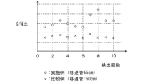
また、本発明者は、実施例および比較例に係るSCDの検出結果から、両者の光検出器により出力される検出信号についてS/N(信号/ノイズ)比を比較した。図3は実施例および比較例に係るSCDのS/N比の比較結果を示す図である。図3のグラフにおいては、縦軸がS/N比を表し、横軸が検出回数を表す。また、図3では、丸印が実施例に対応し、×印が比較例に対応する。S/N比は、各SCDによる硫黄成分の検出ごとに、生成されたクロマトグラムについてASTM(American Society for Testing and Materials)に規定されるノイズの算出方法を適用することにより算出した。図3のグラフによれば、実施例のSCDにより得られる検出信号のS/N比は、1回目から10回目までの全ての回において比較例のSCDにより得られる検出信号のS/N比よりも高い。 Further, the present inventors compared the S/N (signal/noise) ratios of the detection signals output by both photodetectors based on the detection results of the SCDs according to the example and the comparative example. FIG. 3 is a diagram showing a comparison result of S/N ratios of SCDs according to an example and a comparative example. In the graph of FIG. 3, the vertical axis represents the S/N ratio, and the horizontal axis represents the number of detections. Further, in FIG. 3, the circles correspond to the examples, and the x marks correspond to the comparative examples. The S/N ratio was calculated by applying the noise calculation method specified by ASTM (American Society for Testing and Materials) to the generated chromatogram for each detection of a sulfur component by each SCD. According to the graph in FIG. 3, the S/N ratio of the detection signal obtained by the SCD of the example is higher than the S/N ratio of the detection signal obtained by the SCD of the comparative example in all times from the 1st to the 10th time. It's also expensive.
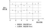
また、本発明者は、実施例および比較例に係るSCDの各検出結果から、両者において単位時間当たりに検出可能と考えられる硫黄成分の最小量(以下、最小検出量と呼ぶ。)を比較した。図4は実施例および比較例に係るSCDの最小検出量の比較結果を示す図である。図4のグラフにおいては、縦軸が最小検出量を表し、横軸が検出回数を表す。また、図4では、丸印が実施例に対応し、×印が比較例に対応する。最小検出量は、各SCDによる硫黄成分の検出ごとに、生成されたクロマトグラムに基づいて算出した。図4のグラフによれば、実施例のSCDの最小検出量は、1回目から10回目までの全ての回において比較例のSCDの最小検出量よりも低い。 In addition, the present inventor compared the minimum amount of sulfur components that can be detected per unit time (hereinafter referred to as the minimum detected amount) in both of the detection results of the SCD according to the example and the comparative example. . FIG. 4 is a diagram showing a comparison result of the minimum detection amount of the SCD according to the example and the comparative example. In the graph of FIG. 4, the vertical axis represents the minimum detection amount, and the horizontal axis represents the number of detections. Moreover, in FIG. 4, circles correspond to examples, and cross marks correspond to comparative examples. The minimum detection amount was calculated based on the chromatogram generated for each detection of sulfur component by each SCD. According to the graph of FIG. 4, the minimum detection amount of the SCD of the example is lower than the minimum detection amount of the SCD of the comparative example at all times from the first to the tenth time.
さらに、本発明者は、実施例および比較例に係るSCDの各検出結果から、両者における硫黄成分の選択性を比較した。図5は実施例および比較例に係るSCDの硫黄成分の選択性の比較結果を示す図である。図5のグラフにおいては、縦軸が選択性を表し、横軸が検出回数を表す。また、図5では、丸印が実施例に対応し、×印が比較例に対応する。選択性は、各SCDによる硫黄成分の検出ごとに、生成されたクロマトグラムから硫黄成分および試料の溶媒成分にそれぞれ対応するピークを抽出し、硫黄成分のピークの面積値を溶媒成分のピークの面積値で除算することにより求めた。図5のグラフによれば、実施例のSCDにおける硫黄成分の選択性は、1回目から10回目までの全ての回において比較例のSCDにおける硫黄成分の選択性よりも高い。 Furthermore, the present inventors compared the selectivity of the sulfur component in both Examples and Comparative Examples based on the detection results of SCD. FIG. 5 is a diagram showing the comparison results of the selectivity of the sulfur component of the SCDs according to Examples and Comparative Examples. In the graph of FIG. 5, the vertical axis represents selectivity, and the horizontal axis represents the number of detections. Further, in FIG. 5, circles correspond to examples, and cross marks correspond to comparative examples. Selectivity is determined by extracting the peaks corresponding to the sulfur component and the solvent component of the sample from the generated chromatogram each time a sulfur component is detected by each SCD, and calculating the area value of the sulfur component peak by calculating the area of the solvent component peak. It was calculated by dividing by the value. According to the graph of FIG. 5, the selectivity of the sulfur component in the SCD of the example is higher than the selectivity of the sulfur component in the SCD of the comparative example in all times from the first to the tenth time.
上記の試験および評価結果から、55cmの移送管を用いる場合には、150cmの移送管を用いる場合に比べて、硫黄成分の検出感度、S/N比、最小検出量および選択性に関する特性が向上することが確認された。 From the above test and evaluation results, when using a 55 cm transfer tube, the characteristics regarding detection sensitivity, S/N ratio, minimum detection amount, and selectivity of sulfur components are improved compared to when using a 150 cm transfer tube. It was confirmed that
[3]酸化還元炉20および反応セル30の複数の配置例
本実施の形態では、酸化還元炉20の上流端21Uと反応セル30の第1の導入部31との間のガス流路の長さを短くするために、酸化還元炉20および反応セル30が一の検出装置ケーシング3C内に収容されている。
[3] Multiple arrangement examples of
ここで、本例の検出装置ケーシング3Cは、略直方体形状を有し、互いに異なる方向を向く6つの外面を有する。検出装置ケーシング3Cの6つの外面のうち1つの外面は、成分分析システム1の使用時に、使用者に対向するように配置される。この外面を検出装置ケーシング3Cの前面と呼び、前面に平行でかつ前面に対向する外面を後面と呼ぶ。また、検出装置ケーシング3C内の中心部から前面を見た状態で、当該中心部の右方に位置する外面を右側面と呼び、当該中心部の左方に位置する外面を左側面と呼ぶ。さらに、検出装置ケーシング3Cにおいて、上方を向く外面を上面と呼び、下方を向く外面を下面と呼ぶ。
Here, the
また、以下の説明では、検出装置ケーシング3C内の中心部を基準として、前面を向く方向、後面を向く方向、右側面を向く方向、左側面を向く方向、上面を向く方向および下面を向く方向を、それぞれ成分検出装置3の前方、後方、右方、左方、上方および下方と呼ぶ。
In addition, in the following description, the directions will be directed to the front, the rear, the right side, the left side, the top, and the bottom, with the center of the detection device casing 3C as a reference. are referred to as the front, rear, right, left, upper, and lower of the
以下、検出装置ケーシング3C内部における酸化還元炉20および反応セル30の複数の配置例について説明する。
Hereinafter, a plurality of arrangement examples of the
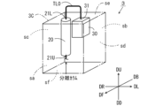
(a)第1の配置例
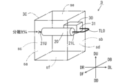
図6は酸化還元炉20および反応セル30の第1の配置例を説明するための模式的斜視図である。図6および後述する図7~図14においては、検出装置ケーシング3Cが一点鎖線で示されるとともに、酸化還元炉20および反応セル30が実線で示される。また、成分検出装置3における前方DF、後方DB、右方DR、左方DL、上方DUおよび下方DDを示す3つの矢印が示される。
(a) First example of arrangement FIG. 6 is a schematic perspective view for explaining a first example of arrangement of the
第1の配置例においては、酸化還元炉20および反応セル30は、検出装置ケーシング3C内で前後方向に並ぶ。具体的には、酸化還元炉20は、反応セル30の前方DFに位置する。また、酸化還元炉20は、上流端21Uが右方DRを向き、下流端21Lが左方DLを向くように左右方向に延びる。このように、第1の配置例では酸化還元炉20および反応セル30が並ぶ方向に対して、酸化還元炉20の長手方向が交差している。反応セル30は、第1の導入部31が左方DLを向く。この配置によれば、下流端21Lの向く方向と第1の導入部31の向く方向とが一致するので、移送管TL0の長さをより短くすることができる。
In the first arrangement example, the
また、酸化還元炉20の上流端21Uが右方DRを向くので、成分検出装置3の右方DRにガスクロマトグラフ2を配置することにより、ガスクロマトグラフ2および成分検出装置3間のガス流路の長さを短くすることができる。
Furthermore, since the
また、第1の配置例においては、酸化還元炉20の下流端21Lと反応セル30の第1の導入部31とが酸化還元炉20の長手方向に直交する共通の面(本例では、左側面sd)内に配置される。それにより、移送管TL0の長さをさらに短くすることができる。
In the first arrangement example, the
第1の配置例においては、酸化還元炉20が反応セル30と同じ高さに位置する。この場合、酸化還元炉20において発生する熱により加熱された雰囲気が上昇する場合でも、反応セル30に近接して設けられる光検出器40(図1)が酸化還元炉20において発生する熱の影響を受けにくい。したがって、熱による光検出器40の検出精度の低下が抑制されるとともに短寿命化が抑制される。
In the first arrangement example, the
移送管TL0は、検出装置ケーシング3Cの外部において酸化還元炉20の下流端21Lと反応セル30の第1の導入部31とに着脱可能に設けられることが好ましい。この場合、検出装置ケーシング3Cの外部から酸化還元炉20および反応セル30のメンテナンスを行うことが可能になる。具体的には、流路形成部材21内部の洗浄、流路形成部材21の交換または反応セル30内の洗浄等を行うことができる。したがって、成分検出装置3のメンテナンス性が向上する。
It is preferable that the transfer pipe TL0 is detachably provided to the
ここで、酸化還元炉20において、酸化に適した温度(約1000℃)は還元に適した温度(約850℃)よりも高い。この点に関して、第1の配置例においては、酸化還元炉20の流路形成部材21が左右方向に延びるので、酸化還元炉20における酸化部22および還元部23が左右方向に並ぶ。この場合、還元部23が酸化部22の上方DUに位置しないので、還元部23の温度環境が酸化部22の周囲で加熱された雰囲気の影響を受けにくい。すなわち、還元部23の温度が酸化部22の温度により過剰に上昇しない。したがって、流路形成部材21における酸化還元反応が適切に行われる。
Here, in the
なお、第1の配置例においては、検出装置ケーシング3C内における酸化還元炉20および反応セル30の位置が左右方向に直交する鉛直面を基準として反転されてもよい(左右方向の反転)。この場合、酸化還元炉20の上流端21Uが左方DLを向く。それにより、成分検出装置3の左方DLにガスクロマトグラフ2を配置することにより、ガスクロマトグラフ2および成分検出装置3間のガス流路の長さを短くすることができる。
In the first arrangement example, the positions of the
また、第1の配置例においては、検出装置ケーシング3C内における酸化還元炉20および反応セル30の位置が前後方向に直交する鉛直面を基準として反転されてもよい(前後方向の反転)。すなわち、酸化還元炉20および反応セル30の位置が入れ替えられてもよい。
Further, in the first arrangement example, the positions of the
(b)第2の配置例
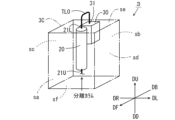
図7は酸化還元炉20および反応セル30の第2の配置例を説明するための模式的斜視図である。第2の配置例は、酸化還元炉20が上下方向に延びるように設けられる点が第1の配置例と異なる。具体的には、酸化還元炉20は、反応セル30の前方DFの位置で、上流端21Uが下方DDを向き、下流端21Lが上方DUを向くように上下方向に延びる。本例においても、酸化還元炉20および反応セル30が並ぶ方向に対して、酸化還元炉20の長手方向は交差している。反応セル30は、第1の導入部31が上方DUを向く。この配置によれば、下流端21Lの向く方向と第1の導入部31の向く方向とが一致するので、移送管TL0の長さをより短くすることができる。
(b) Second arrangement example FIG. 7 is a schematic perspective view for explaining a second arrangement example of the
また、酸化還元炉20の上流端21Uが下方DDを向くので、成分検出装置3の下方DDにガスクロマトグラフ2を配置することにより、ガスクロマトグラフ2および成分検出装置3間のガス流路の長さを短くすることができる。
Furthermore, since the
本例においても、第1の配置例と同様に、酸化還元炉20の下流端21Lと反応セル30の第1の導入部31とが酸化還元炉20の長手方向に直交する共通の面(本例では、上面se)内に配置される。それにより、移送管TL0の長さをさらに短くすることができる。
In this example as well, similarly to the first arrangement example, the
また、第1の配置例と同様に、移送管TL0は、検出装置ケーシング3Cの外部において酸化還元炉20の下流端21Lと反応セル30の第1の導入部31とに着脱可能に設けられることが好ましい。それにより、成分検出装置3のメンテナンス性が向上する。
Further, similarly to the first arrangement example, the transfer pipe TL0 is detachably provided to the
なお、第2の配置例においては、検出装置ケーシング3C内における酸化還元炉20および反応セル30の位置が前後方向に直交する鉛直面を基準として反転されてもよい(前後方向の反転)。すなわち、酸化還元炉20および反応セル30の位置が入れ替えられてもよい。
In the second arrangement example, the positions of the
また、第2の配置例においては、検出装置ケーシング3C内における酸化還元炉20および反応セル30の位置が水平面を基準として反転されてもよい(上下方向の反転)。この場合、酸化還元炉20において、酸化部22が還元部23よりも上方に位置することになる。それにより、還元部23の温度環境が酸化部22の周囲で加熱された雰囲気の影響を受けにくい。したがって、流路形成部材21における酸化還元反応が適切に行われる。
Furthermore, in the second arrangement example, the positions of the
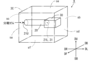
(c)第3の配置例
図8は酸化還元炉20および反応セル30の第3の配置例を説明するための模式的斜視図である。図8に示すように、第3の配置例は、酸化還元炉20および反応セル30が検出装置ケーシング3C内で上下方向に並ぶ点が第1の配置例と異なる。本例においても、酸化還元炉20および反応セル30が並ぶ方向に対して、酸化還元炉20の長手方向は交差している。具体的には、図8の例では、酸化還元炉20が反応セル30の上方に位置する。この場合、酸化還元炉20において発生する熱が光検出器40(図1)に及ぼす影響をより低減することができる。この点を除いて、図8に示される第3の配置例によれば、第1の配置例と同様の効果を得ることができる。
(c) Third arrangement example FIG. 8 is a schematic perspective view for explaining a third arrangement example of the
なお、第3の配置例においては、検出装置ケーシング3C内における酸化還元炉20および反応セル30の位置が左右方向に直交する鉛直面を基準として反転されてもよい(左右方向の反転)。
In the third arrangement example, the positions of the
また、第3の配置例においては、検出装置ケーシング3C内における酸化還元炉20および反応セル30の位置が水平面を基準として反転されてもよい(上下方向の反転)。すなわち、酸化還元炉20および反応セル30の位置が入れ替えられてもよい。
In the third arrangement example, the positions of the
(d)第4の配置例
図9は酸化還元炉20および反応セル30の第4の配置例を説明するための模式的斜視図である。第4の配置例は、酸化還元炉20および反応セル30が検出装置ケーシング3C内で左右方向に並ぶ点が第2の配置例と異なる。本例においても、酸化還元炉20および反応セル30が並ぶ方向に対して、酸化還元炉20の長手方向は交差している。具体的には、酸化還元炉20が反応セル30の右方DRに位置する。本例においても、第2の配置例と同様の効果を得ることができる。
(d) Fourth arrangement example FIG. 9 is a schematic perspective view for explaining a fourth arrangement example of the
なお、第4の配置例においては、検出装置ケーシング3C内における酸化還元炉20および反応セル30の位置が左右方向に直交する鉛直面を基準として反転されてもよい(左右方向の反転)。すなわち、酸化還元炉20および反応セル30の位置が入れ替えられてもよい。
In the fourth arrangement example, the positions of the
また、第4の配置例においては、検出装置ケーシング3C内における酸化還元炉20および反応セル30の位置が水平面を基準として反転されてもよい(上下方向の反転)。
Furthermore, in the fourth arrangement example, the positions of the
(e)第5の配置例
図10は酸化還元炉20および反応セル30の第5の配置例を説明するための模式的斜視図である。第5の配置例は、酸化還元炉20が左右方向に延びるように設けられる点が第4の配置例と異なる。本例では、酸化還元炉20および反応セル30が並ぶ方向と酸化還元炉20の長手方向とが平行であり一致している。さらに、本例では、反応セル30は、第1の導入部31が酸化還元炉20の下流端21Lに対向するように配置される。この構成によれば、移送管TL0の長さをより短くすることができる。なお、酸化還元炉20および反応セル30の位置が入れ替えられてもよい。
(e) Fifth example of arrangement FIG. 10 is a schematic perspective view for explaining a fifth example of arrangement of the oxidation-
(f)第6の配置例
図11は酸化還元炉20および反応セル30の第6の配置例を説明するための模式的斜視図である。第6の配置例は、酸化還元炉20が上下方向に延びるように設けられる点が第3の配置例と異なる。本例では、酸化還元炉20および反応セル30が並ぶ方向と酸化還元炉20の長手方向とが平行であり一致している。さらに、本例では、反応セル30は、酸化還元炉20に対して上下方向に並ぶようにかつ第1の導入部31が酸化還元炉20の下流端21Lに対向するように配置される。この構成によれば、移送管TL0の長さをより短くすることができる。なお、酸化還元炉20および反応セル30の位置が入れ替えられてもよい。
(f) Sixth example of arrangement FIG. 11 is a schematic perspective view for explaining a sixth example of arrangement of the
(g)第7の配置例
図12は酸化還元炉20および反応セル30の第7の配置例を説明するための模式的斜視図である。第7の配置例は、酸化還元炉20の下流端21Lと反応セル30の第1の導入部31とが直接接続される点が第5の配置例と異なる。この構成によれば、酸化還元炉20において生成される一酸化硫黄が変質することなく反応セル30に導入される。なお、酸化還元炉20および反応セル30の位置が入れ替えられてもよい。
(g) Seventh example of arrangement FIG. 12 is a schematic perspective view for explaining a seventh example of arrangement of the
(h)第8の配置例
図13は酸化還元炉20および反応セル30の第8の配置例を説明するための模式的斜視図である。第8の配置例は、酸化還元炉20の下流端21Lと反応セル30の第1の導入部31とが直接接続される点が第6の配置例と異なる。この構成によれば、酸化還元炉20において生成される一酸化硫黄が変質することなく反応セル30に導入される。なお、酸化還元炉20および反応セル30の位置が入れ替えられてもよい。
(h) Eighth Arrangement Example FIG. 13 is a schematic perspective view for explaining an eighth arrangement example of the
(i)その他
上記の第1~4の配置例において、反応セル30の第1の導入部31は、酸化還元炉20の下流端21Lが向く方向とは異なる方向に向くように設けられてもよい。この場合、第1の導入部31は、酸化還元炉20を向くように設けられることが好ましい。図14は第3の配置例において第1の導入部31が酸化還元炉20を向くように設けられた状態を示す模式的斜視図である。
(i) Others In the first to fourth arrangement examples described above, the
図14の例では、反応セル30が酸化還元炉20の下方に配置されている。また、反応セル30には、酸化還元炉20を向くように第1の導入部31が設けられている。これにより、第1の導入部31が酸化還元炉20を向かないように設けられる場合に比べて、移送管TL0の長さを短くすることができる。
In the example of FIG. 14, the
なお、本例においても、酸化還元炉20および反応セル30の位置が入れ替えられてもよい。また、本例においても、移送管TL0は、検出装置ケーシング3Cの外部において酸化還元炉20の下流端21Lに着脱可能に設けられることが好ましい。それにより、酸化還元炉20のメンテナンスが可能になる。
In addition, also in this example, the positions of the
上記の第1~第8の配置例では、酸化還元炉20は、検出装置ケーシング3C内で上下方向または左右方向に延びるように設けられているが、酸化還元炉20は検出装置ケーシング3C内で前後方向に延びるように設けられてもよい。この場合、左右方向および上下方向における検出装置ケーシング3Cのサイズを低減することができる。
In the first to eighth arrangement examples described above, the
[4]効果
(a)本実施の形態に係る成分検出装置3においては、酸化還元炉20および反応セル30が一の検出装置ケーシング3Cに収容されるので、酸化還元炉20と反応セル30との間の距離を短くすることができる。それにより、酸化還元炉20の下流端21Lと反応セル30の第1の導入部31とを、互いに接続することまたは比較的短い長さを有する移送管TL0を介して接続することが可能である。この場合、酸化還元炉20において還元された一酸化硫黄の大部分が反応セル30に到達するまでの間に変質しないように、一酸化硫黄の移送時間を低減することができる。したがって、反応セル30において、硫黄成分の検出に要する化学反応を安定して発生させることが可能になる。その結果、分離カラム12により分離された硫黄成分を高い精度で検出することが可能になる。
[4] Effect (a) In the
(b)酸化還元炉20においては、分離カラム12から多量の溶剤(有機物)が導入される際に、溶剤に起因してOHラジカルおよびCHラジカル等の化合物も生成される場合がある。OHラジカルおよびCHラジカルは、反応セル30においてオゾンと反応することにより、光を発生する。これらの光の波長は、一酸化硫黄がオゾンと反応することにより発生する光の波長に近い。そのため、OHラジカルおよびCHラジカルの反応により発生する光は、光学フィルタFを通して光検出器40により検出されることになる。したがって、反応セル30に到達する一酸化硫黄に比べてOHラジカルおよびCHラジカルが多いと、SCDのS/N比が低下する。
(b) In the
また、本発明者は、酸化還元炉20により生成された一酸化硫黄およびOHラジカルの単位時間当たりの変質の程度についてシミュレーションを行った。その結果、一酸化硫黄の変質の程度は、OHラジカルの変質の程度に比べて大きいことが確認された。すなわち、一酸化硫黄は、酸化還元炉において溶剤に起因して生成されるOHラジカルに比べて反応セルへの移送中に変質しやすいことが確認された。このことは、酸化還元炉20から反応セル30までの移送時間が長くなるほど、硫黄成分の選択性が低下することを意味する。
Further, the present inventor conducted a simulation regarding the degree of deterioration of sulfur monoxide and OH radicals generated by the
これらの点に関して、本実施の形態に係る成分検出装置3によれば、酸化還元炉20から反応セル30までの移送時間が十分に短くなる。したがって、移送時における一酸化硫黄の変質が抑制されるので、SCDにおける硫黄検出のS/N比の低下および硫黄成分の選択性の低下が抑制される。その結果、高い精度で試料中の硫黄成分を検出することが可能となっている。
Regarding these points, according to the
[5]他の実施の形態
(a)上記実施の形態では、酸化還元炉20から反応セル30に至るガス流路を短くするために、酸化還元炉20と反応セル30とが一の検出装置ケーシング3C内に収容されるが、実施の形態はこれに限定されない。酸化還元炉20から反応セル30に至るガス流路の長さが100cm以下となるのであれば、酸化還元炉20と反応セル30とは、互いに異なるケーシングに収容されてもよい。この場合においても、酸化還元炉20から反応セル30に至るガス流路の長さが100cm以下であることにより、上記実施の形態と同様の効果を得ることができる。
[5] Other Embodiments (a) In the above embodiment, in order to shorten the gas flow path from the oxidation-
(b)上記実施の形態では、成分検出装置3がSCDである例について説明したが、本実施の形態に係る成分検出装置3は試料中の窒素成分を検出する化学発光窒素検出器(NCD:Nitrogen Chemiluminesence Detector)に適用することもできる。
(b) In the above embodiment, an example was explained in which the
この場合、酸化還元炉20においては、試料中の窒素成分が酸化および還元されることにより一酸化窒素が生成される。生成された一酸化窒素が、上記の移送管TL0を通してまたは直接反応セル30に導入される。それにより、酸化還元炉20から反応セル30への移送時における一酸化窒素の変質が抑制される。その結果、試料中の窒素成分を高い精度で検出することが可能になる。
In this case, in the
なお、成分検出装置3がNCDに適用される場合、図1の光学フィルタFが透過させる特定の波長領域は、オゾンと一酸化窒素とが反応することにより発生する光(二酸化窒素が基底状態に遷移する際に発生する光)の波長を含むように定められる。
Note that when the
(c)上記実施の形態では、一の検出装置ケーシング3C内に、酸化還元炉20、反応セル30、光検出器40、制御部50、フローコントローラ60、オゾン発生器70、スクラバ80およびポンプ90が収容されるが、実施の形態はこれに限定されない。制御部50、フローコントローラ60、オゾン発生器70、スクラバ80およびポンプ90のうち少なくとも一部が、検出装置ケーシング3Cの外部に設けられてもよい。
(c) In the above embodiment, a
[6]請求項の各構成要素と実施の形態の各部との対応関係
以下、請求項の各構成要素と実施の形態の各部との対応の例について説明する。上記実施の形態においては、流路形成部材21により形成されるガス流路が第1の流路の例であり、反応セル30の第1の導入部31が反応セルの導入部の例であり、検出装置ケーシング3Cが保持部材の例であり、流路形成部材21の下流端21Lが第1の流路の下流端の例であり、移送管TL0により形成されるガス流路が第2の流路の例である。
[6] Correspondence between each component of the claims and each part of the embodiment Hereinafter, an example of the correspondence between each component of the claim and each part of the embodiment will be described. In the embodiment described above, the gas flow path formed by the flow
また、左方DLまたは右方DRが第1の方向および一方向の例であり、前方DFまたは後方DBが第2の方向の例であり、右側面sc、左側面sdまたは上面seが共通の面の例である。 Further, the left side DL or right side DR is an example of the first direction and one direction, the front DF or rear DB is an example of the second direction, and the right side sc, left side sd, or top surface se is a common direction. This is an example of a surface.
請求項の各構成要素として、請求項に記載されている構成または機能を有する他の種々の要素を用いることもできる。 Various other elements having the configuration or function described in the claims can also be used as each component in the claims.
[7]態様
上述した複数の例示的な実施の形態は、以下の態様の具体例であることが当業者により理解される。
[7] Aspects Those skilled in the art will understand that the multiple exemplary embodiments described above are specific examples of the following aspects.
(第1項)一態様に係る成分分析システムは、
分離カラムを有するガスクロマトグラフと、
成分検出装置とを備え、
前記成分検出装置は、
前記分離カラムにより分離された試料成分を含むガスが流れる第1の流路を有し、前記第1の流路を流れるガス中の試料成分を酸化および還元させる酸化還元炉と、
前記還元された試料成分を含むガスの導入部を有し、前記導入部から導入される試料成分について発光を伴う化学反応を発生させる反応セルと、
前記反応セルにおいて発生される光を検出する光検出器と、
前記酸化還元炉および前記反応セルを保持する保持部材とを含み、
前記第1の流路の下流端と前記反応セルの前記導入部とは、直接接続されるかまたは第2の流路を介して接続されていてよい。
(Paragraph 1) The component analysis system according to one embodiment includes:
a gas chromatograph having a separation column;
Equipped with a component detection device,
The component detection device includes:
a redox furnace having a first flow path through which a gas containing sample components separated by the separation column flows, and oxidizing and reducing sample components in the gas flowing through the first flow path;
a reaction cell having an introduction section for a gas containing the reduced sample component, and causing a chemical reaction accompanied by light emission with respect to the sample component introduced from the introduction section;
a photodetector that detects light generated in the reaction cell;
a holding member that holds the oxidation-reduction furnace and the reaction cell;
The downstream end of the first channel and the introduction part of the reaction cell may be connected directly or via a second channel.
その成分分析システムにおいては、分離カラムにより分離された試料成分が成分検出装置により検出される。成分検出装置においては、酸化還元炉および反応セルが保持部材により一体として保持されるので、酸化還元炉と反応セルとの間の距離を短くすることができる。それにより、第1の流路の下流端と反応セルの導入部とを、直接接続することまたは比較的短い長さを有する第2の流路を介して接続することが可能である。この場合、酸化還元炉において還元された試料成分が反応セルに到達するまでの間に変質しないように、酸化還元炉から反応セルに到達するまでに要する時間を低減することができる。したがって、反応セルにおいて、試料成分の検出に要する化学反応を安定して発生させることが可能になる。その結果、分離カラムにより分離された試料成分を高い精度で検出することが可能になる。 In this component analysis system, sample components separated by a separation column are detected by a component detection device. In the component detection device, since the redox furnace and the reaction cell are held together by the holding member, the distance between the redox furnace and the reaction cell can be shortened. Thereby, it is possible to connect the downstream end of the first channel and the introduction part of the reaction cell directly or via a second channel having a relatively short length. In this case, the time required for the sample components to reach the reaction cell from the redox furnace can be reduced so that the sample components reduced in the redox furnace do not change in quality before reaching the reaction cell. Therefore, in the reaction cell, it becomes possible to stably generate a chemical reaction required for detection of sample components. As a result, it becomes possible to detect sample components separated by the separation column with high precision.
(第2項)第1項に記載の成分分析システムにおいて、
前記化学反応は、前記分離カラムにより分離された試料成分に硫黄が含まれる場合に、前記酸化還元炉により還元された硫黄成分をオゾンで励起する化学反応であってもよい。
(Section 2) In the component analysis system described in
The chemical reaction may be a chemical reaction in which, when the sample component separated by the separation column contains sulfur, the sulfur component reduced by the redox furnace is excited with ozone.
試料に硫黄成分が含まれる場合には、酸化還元炉において生成される一酸化硫黄が反応セルでオゾンと反応することにより光が発生される。一酸化硫黄は、酸化還元炉において溶剤に起因して生成される他の化合物に比べて反応セルへの移送中に変質しやすい。しかしながら、上記の構成によれば反応セルへの移送中の一酸化硫黄の変質が抑制されるので、高い精度で試料中の硫黄成分を検出することが可能になる。 If the sample contains sulfur components, light is generated when sulfur monoxide produced in the redox reactor reacts with ozone in the reaction cell. Sulfur monoxide is more susceptible to deterioration during transfer to the reaction cell than other compounds produced due to solvents in the redox furnace. However, according to the above configuration, deterioration of the sulfur monoxide during transfer to the reaction cell is suppressed, so that it becomes possible to detect the sulfur component in the sample with high accuracy.
(第3項)第1または第2項に記載の成分分析システムにおいて、
前記酸化還元炉は、前記第1の流路が上流端から前記下流端にかけて第1の方向に延びるように形成され、
前記反応セルは、前記酸化還元炉に対して前記第1の方向に交差する第2の方向に並ぶように配置され、
前記第1の流路の下流端と前記反応セルの前記導入部とは、前記第2の流路を介して接続されてもよい。
(Section 3) In the component analysis system according to
The redox furnace is formed such that the first flow path extends in a first direction from the upstream end to the downstream end,
The reaction cells are arranged in a second direction intersecting the first direction with respect to the redox furnace,
The downstream end of the first channel and the introduction section of the reaction cell may be connected via the second channel.
上記の構成によれば、第1の方向における成分検出装置の大型化を抑制することができる。 According to the above configuration, it is possible to suppress the component detection device from increasing in size in the first direction.
(第4項)第3項に記載の成分分析システムにおいて、
前記反応セルは、前記導入部が前記第1の方向に向くように配置されてもよい。
(Section 4) In the component analysis system described in
The reaction cell may be arranged such that the introduction part faces the first direction.
上記の構成によれば、第1の流路の下流端と反応セルの導入部とを接続する第2の流路を短くすることができる。 According to the above configuration, the second flow path connecting the downstream end of the first flow path and the introduction part of the reaction cell can be shortened.
(第5項)第4項に記載の成分分析システムにおいて、
前記酸化還元炉および前記反応セルは、前記第1の流路の前記下流端と前記反応セルの前記導入部とが前記第1の方向に直交する共通の面内に位置するように配置されてもよい。
(Section 5) In the component analysis system described in
The oxidation-reduction furnace and the reaction cell are arranged such that the downstream end of the first flow path and the introduction part of the reaction cell are located in a common plane orthogonal to the first direction. Good too.
この場合、第2の流路をより短くすることができる。 In this case, the second flow path can be made shorter.
(第6項)第1または第2項に記載の成分分析システムにおいて、
前記第1の流路の下流端と前記反応セルの前記導入部とは、前記第2の流路を介して接続され、
前記第2の流路は、前記保持部材の外部において前記第1の流路の前記下流端および前記反応セルの前記導入部に着脱可能に設けられてもよい。
(Section 6) In the component analysis system according to
The downstream end of the first channel and the introduction part of the reaction cell are connected via the second channel,
The second flow path may be removably provided at the downstream end of the first flow path and the introduction part of the reaction cell outside the holding member.
この場合、保持部材の外部において第2の流路を第1の流路の下流端および反応セルの導入部から取り外すことにより、保持部材の外部から酸化還元炉および反応セルのメンテナンスを行うことができる。 In this case, by removing the second flow path from the downstream end of the first flow path and the introduction part of the reaction cell outside the holding member, maintenance of the redox furnace and the reaction cell can be performed from outside the holding member. can.
(第7項)第1または第2項に記載の成分分析システムにおいて、
前記酸化還元炉は、前記第1の流路が上流端から下流端にかけて一方向に延びるように形成され、
前記反応セルは、前記酸化還元炉に対して前記一方向に並ぶようにかつ前記導入部が前記第1の流路の前記下流端に対向するように配置されてもよい。
(Section 7) In the component analysis system according to
The redox furnace is formed such that the first flow path extends in one direction from an upstream end to a downstream end,
The reaction cells may be arranged so as to be lined up in the one direction with respect to the oxidation-reduction furnace, and so that the introduction section faces the downstream end of the first flow path.
この場合、酸化還元炉から反応セルまでの試料成分の流路をより短くすることができる。 In this case, the flow path for sample components from the redox furnace to the reaction cell can be made shorter.
(第8項)第1または第2項に記載の成分分析システムにおいて、
前記第1の流路の前記下流端と前記反応セルの前記導入部とは、前記第2の流路を介して接続され、
前記第2の流路の長さは、100cm以下であってもよい。
(Section 8) In the component analysis system according to
The downstream end of the first flow path and the introduction part of the reaction cell are connected via the second flow path,
The length of the second channel may be 100 cm or less.
これにより、酸化還元炉において還元された試料成分が、反応セルに到達するまでの間に、許容される程度を超えて変質しない。それにより、分離カラムにより分離された試料成分を高い精度で検出することが可能になる。 This prevents the sample components reduced in the redox furnace from deteriorating beyond a permissible level before reaching the reaction cell. This makes it possible to detect sample components separated by the separation column with high precision.
(第9項)他の態様に係る成分検出装置は、
分離カラムを有するガスクロマトグラフとともに用いられる成分検出装置であって、
前記分離カラムにより分離された試料成分を含むガスが流れる第1の流路を有し、前記第1の流路を流れるガス中の試料成分を酸化および還元させる酸化還元炉と、
前記還元された試料成分を含むガスの導入部を有し、前記導入部から導入される試料成分について発光を伴う化学反応を発生させる反応セルと、
前記反応セルにおいて発生される光を検出する光検出器と、
前記酸化還元炉および前記反応セルを保持する保持部材とを備え、
前記第1の流路の下流端と前記反応セルの前記導入部とは、直接接続されるかまたは第2の流路を介して接続されていてよい。
(Section 9) A component detection device according to another aspect,
A component detection device used with a gas chromatograph having a separation column,
a redox furnace having a first flow path through which a gas containing sample components separated by the separation column flows, and oxidizing and reducing sample components in the gas flowing through the first flow path;
a reaction cell having an introduction section for a gas containing the reduced sample component, and causing a chemical reaction accompanied by light emission with respect to the sample component introduced from the introduction section;
a photodetector that detects light generated in the reaction cell;
comprising a holding member that holds the oxidation-reduction furnace and the reaction cell,
The downstream end of the first channel and the introduction section of the reaction cell may be connected directly or via a second channel.
その成分検出装置においては、酸化還元炉および反応セルが保持部材により一体として保持されるので、酸化還元炉と反応セルとの間の距離を短くすることができる。それにより、第1の流路の下流端と反応セルの導入部とを、直接接続することまたは比較的短い長さを有する第2の流路を介して接続することが可能である。この場合、酸化還元炉において還元された試料成分が反応セルに到達するまでの間に変質しないように、酸化還元炉から反応セルに到達するまでに要する時間を低減することができる。したがって、反応セルにおいて、試料成分の検出に要する化学反応を安定して発生させることが可能になる。その結果、分離カラムにより分離された試料成分を高い精度で検出することが可能になる。 In this component detection device, the redox furnace and the reaction cell are held together by the holding member, so the distance between the redox furnace and the reaction cell can be shortened. Thereby, it is possible to connect the downstream end of the first channel and the introduction part of the reaction cell directly or via a second channel having a relatively short length. In this case, the time required for the sample components to reach the reaction cell from the redox furnace can be reduced so that the sample components reduced in the redox furnace do not change in quality before reaching the reaction cell. Therefore, in the reaction cell, it becomes possible to stably generate a chemical reaction required for detection of sample components. As a result, it becomes possible to detect sample components separated by the separation column with high precision.
(第10項)さらに他の態様に係る成分分析システムは、
分離カラムを有するガスクロマトグラフと、
成分検出装置とを備え、
前記成分検出装置は、
前記分離カラムにより分離された試料成分を含むガスが流れる第1の流路を有し、前記第1の流路を流れるガス中の試料成分を酸化および還元させる酸化還元炉と、
前記還元された試料成分を含むガスの導入部を有し、前記導入部から導入される試料成分について発光を伴う化学反応を発生させる反応セルと、
前記反応セルにおいて発生される光を検出する光検出器とを含み、
前記第1の流路の下流端と前記反応セルの前記導入部とは、互いに接続されるかまたは100cm以下の長さを有する第2の流路を介して接続されていてよい。
(Section 10) A component analysis system according to still another aspect,
a gas chromatograph having a separation column;
Equipped with a component detection device,
The component detection device includes:
a redox furnace having a first flow path through which a gas containing sample components separated by the separation column flows, and oxidizing and reducing sample components in the gas flowing through the first flow path;
a reaction cell having an introduction section for a gas containing the reduced sample component, and causing a chemical reaction accompanied by light emission with respect to the sample component introduced from the introduction section;
a photodetector for detecting light generated in the reaction cell;
The downstream end of the first channel and the introduction part of the reaction cell may be connected to each other or via a second channel having a length of 100 cm or less.
その成分分析システムにおいては、分離カラムにより分離された試料成分が成分検出装置により検出される。成分検出装置においては、第1の流路の下流端と反応セルの導入部とが、互いに接続されるかまたは100cm以下の長さを有する第2の流路を介して接続される。この場合、酸化還元炉において還元された試料成分が、反応セルに到達するまでの間に、許容される程度を超えて変質しないように、酸化還元炉から反応セルに到達するまでに要する時間を低減することができる。したがって、反応セルにおいて、試料成分の検出に要する化学反応を安定して発生させることが可能になる。その結果、分離カラムにより分離された試料成分を高い精度で検出することが可能になる。 In this component analysis system, sample components separated by a separation column are detected by a component detection device. In the component detection device, the downstream end of the first channel and the introduction part of the reaction cell are connected to each other or via a second channel having a length of 100 cm or less. In this case, in order to prevent the sample components reduced in the redox furnace from deteriorating beyond the permissible level before reaching the reaction cell, the time required for the sample components to reach the reaction cell from the redox furnace is can be reduced. Therefore, in the reaction cell, it becomes possible to stably generate a chemical reaction required for detection of sample components. As a result, it becomes possible to detect sample components separated by the separation column with high precision.
(第11項)さらに他の態様に係る成分検出装置は、
分離カラムを有するガスクロマトグラフとともに用いられる成分検出装置であって、
前記分離カラムにより分離された試料成分を含むガスが流れる第1の流路を有し、前記第1の流路を流れるガス中の試料成分を酸化および還元させる酸化還元炉と、
前記還元された試料成分を含むガスの導入部を有し、前記導入部から導入される試料成分について発光を伴う化学反応を発生させる反応セルと、
前記反応セルにおいて発生される光を検出する光検出器とを備え、
前記第1の流路の下流端と前記反応セルの前記導入部とは、互いに接続されるかまたは100cm以下の長さを有する第2の流路を介して接続されていてよい。
(Section 11) A component detection device according to still another aspect includes:
A component detection device used with a gas chromatograph having a separation column,
a redox furnace having a first flow path through which a gas containing sample components separated by the separation column flows, and oxidizing and reducing sample components in the gas flowing through the first flow path;
a reaction cell having an introduction section for a gas containing the reduced sample component, and causing a chemical reaction accompanied by light emission with respect to the sample component introduced from the introduction section;
and a photodetector that detects light generated in the reaction cell,
The downstream end of the first channel and the introduction part of the reaction cell may be connected to each other or via a second channel having a length of 100 cm or less.
その成分検出装置においては、第1の流路の下流端と反応セルの導入部とが、互いに接続されるかまたは100cm以下の長さを有する第2の流路を介して接続される。この場合、酸化還元炉において還元された試料成分が、反応セルに到達するまでの間に、許容される程度を超えて変質しないように、酸化還元炉から反応セルに到達するまでに要する時間を低減することができる。したがって、反応セルにおいて、試料成分の検出に要する化学反応を安定して発生させることが可能になる。その結果、分離カラムにより分離された試料成分を高い精度で検出することが可能になる。 In the component detection device, the downstream end of the first channel and the introduction part of the reaction cell are connected to each other or via a second channel having a length of 100 cm or less. In this case, in order to prevent the sample components reduced in the redox furnace from deteriorating beyond the permissible level before reaching the reaction cell, the time required for the sample components to reach the reaction cell from the redox furnace is can be reduced. Therefore, in the reaction cell, it becomes possible to stably generate a chemical reaction required for detection of sample components. As a result, it becomes possible to detect sample components separated by the separation column with high precision.
Claims (11)
成分検出装置とを備え、
前記分離カラムは、複数の外面を有するカラムケーシング内に収容され、
前記成分検出装置は、
前記分離カラムにより分離された試料成分を含むガスが流れる第1の流路を有し、前記第1の流路を流れるガス中の試料成分を酸化および還元させる酸化還元炉と、
前記還元された試料成分を含むガスの導入部を有し、前記導入部から導入される試料成分について発光を伴う化学反応を発生させる反応セルと、
前記反応セルにおいて発生される光を検出する光検出器とを含み、
前記第1の流路の下流端と前記反応セルの前記導入部とは、直接接続されるかまたは第2の流路を介して接続され、
前記酸化還元炉および前記反応セルは、前記カラムケーシングの前記複数の外面のうちの一の外面に、ともに対向配置され、
前記酸化還元炉は一方向に延びる長手形状を有し、
前記酸化還元炉と前記反応セルとは前記酸化還元炉の長手方向に交差する方向に並び、
前記酸化還元炉の長手方向に平行な方向において、前記反応セルは酸化還元炉の両端部の範囲内に位置する、成分分析システム。 a gas chromatograph having a separation column;
Equipped with a component detection device,
the separation column is housed within a column casing having a plurality of exterior surfaces;
The component detection device includes:
a redox furnace having a first flow path through which a gas containing sample components separated by the separation column flows, and oxidizing and reducing sample components in the gas flowing through the first flow path;
a reaction cell having an introduction section for a gas containing the reduced sample component, and causing a chemical reaction accompanied by light emission with respect to the sample component introduced from the introduction section;
a photodetector for detecting light generated in the reaction cell;
The downstream end of the first channel and the introduction part of the reaction cell are connected directly or via a second channel,
The oxidation-reduction furnace and the reaction cell are both arranged to face each other on one outer surface of the plurality of outer surfaces of the column casing ,
The redox furnace has a longitudinal shape extending in one direction,
The redox furnace and the reaction cell are arranged in a direction intersecting the longitudinal direction of the redox furnace,
A component analysis system , wherein the reaction cell is located within both ends of the redox furnace in a direction parallel to the longitudinal direction of the redox furnace .
成分検出装置とを備え、 Equipped with a component detection device,
前記分離カラムは、複数の外面を有するカラムケーシング内に収容され、 the separation column is housed within a column casing having a plurality of exterior surfaces;
前記成分検出装置は、 The component detection device includes:
前記分離カラムにより分離された試料成分を含むガスが流れる第1の流路を有し、前記第1の流路を流れるガス中の試料成分を酸化および還元させる酸化還元炉と、 a redox furnace having a first flow path through which a gas containing sample components separated by the separation column flows, and oxidizing and reducing sample components in the gas flowing through the first flow path;
前記還元された試料成分を含むガスの導入部を有し、前記導入部から導入される試料成分について発光を伴う化学反応を発生させる反応セルと、 a reaction cell having an introduction section for a gas containing the reduced sample component, and causing a chemical reaction accompanied by light emission with respect to the sample component introduced from the introduction section;
前記反応セルにおいて発生される光を検出する光検出器とを含み、 a photodetector for detecting light generated in the reaction cell;
前記第1の流路の下流端と前記反応セルの前記導入部とは、直接接続されるかまたは第2の流路を介して接続され、 The downstream end of the first channel and the introduction part of the reaction cell are connected directly or via a second channel,
前記酸化還元炉および前記反応セルは、前記カラムケーシングの前記複数の外面のうちの一の外面に、ともに対向配置され、 The oxidation-reduction furnace and the reaction cell are both arranged to face each other on one outer surface of the plurality of outer surfaces of the column casing,
前記酸化還元炉は、前記反応セルよりも上方に位置する、成分分析システム。 In the component analysis system, the redox furnace is located above the reaction cell.
前記反応セルは、前記酸化還元炉に対して前記第1の方向に交差する第2の方向に並ぶように配置され、
前記第1の流路の下流端と前記反応セルの前記導入部とは、前記第2の流路を介して接続される、請求項1~3のいずれか一項に記載の成分分析システム。 The redox furnace is formed such that the first flow path extends in a first direction from the upstream end to the downstream end,
The reaction cells are arranged in a second direction intersecting the first direction with respect to the redox furnace,
The component analysis system according to any one of claims 1 to 3 , wherein the downstream end of the first channel and the introduction section of the reaction cell are connected via the second channel.
前記第2の流路は、前記第1の流路の前記下流端および前記反応セルの前記導入部に着脱可能に設けられた、請求項1~3のいずれか一項に記載の成分分析システム。 The downstream end of the first channel and the introduction part of the reaction cell are connected via the second channel,
The component analysis system according to any one of claims 1 to 3 , wherein the second flow path is removably provided at the downstream end of the first flow path and the introduction section of the reaction cell. .
前記反応セルは、前記酸化還元炉に対して前記一方向に並ぶようにかつ前記導入部が前記第1の流路の前記下流端に対向するように配置される、請求項2または3記載の成分分析システム。 The redox furnace is formed such that the first flow path extends in one direction from the upstream end to the downstream end,
4. The reaction cells according to claim 2 or 3 , wherein the reaction cells are arranged so as to be lined up in the one direction with respect to the oxidation-reduction furnace, and the introduction part is arranged to face the downstream end of the first flow path. Component analysis system.
前記第2の流路の長さは、100cm以下である、請求項1~3のいずれか一項に記載の成分分析システム。 The downstream end of the first flow path and the introduction part of the reaction cell are connected via the second flow path,
The component analysis system according to any one of claims 1 to 3 , wherein the second flow path has a length of 100 cm or less.
前記分離カラムは、複数の外面を有するカラムケーシング内に収容され、
前記分離カラムにより分離された試料成分を含むガスが流れる第1の流路を有し、前記第1の流路を流れるガス中の試料成分を酸化および還元させる酸化還元炉と、
前記還元された試料成分を含むガスの導入部を有し、前記導入部から導入される試料成分について発光を伴う化学反応を発生させる反応セルと、
前記反応セルにおいて発生される光を検出する光検出器とを備え、
前記第1の流路の下流端と前記反応セルの前記導入部とは、直接接続されるかまたは第2の流路を介して接続され、
前記酸化還元炉および前記反応セルは、前記カラムケーシングの前記複数の外面のうちの一の外面に、ともに対向配置され、
前記酸化還元炉は一方向に延びる長手形状を有し、
前記酸化還元炉と前記反応セルとは前記酸化還元炉の長手方向に交差する方向に並び、
前記酸化還元炉の長手方向に平行な方向において、前記反応セルは酸化還元炉の両端部の範囲内に位置する、成分検出装置。 A component detection device used with a gas chromatograph having a separation column,
the separation column is housed within a column casing having a plurality of exterior surfaces;
a redox furnace having a first flow path through which a gas containing sample components separated by the separation column flows, and oxidizing and reducing sample components in the gas flowing through the first flow path;
a reaction cell having an introduction section for a gas containing the reduced sample component, and causing a chemical reaction accompanied by light emission with respect to the sample component introduced from the introduction section;
and a photodetector that detects light generated in the reaction cell,
The downstream end of the first channel and the introduction part of the reaction cell are connected directly or via a second channel,
The oxidation-reduction furnace and the reaction cell are both arranged to face each other on one outer surface of the plurality of outer surfaces of the column casing ,
The redox furnace has a longitudinal shape extending in one direction,
The redox furnace and the reaction cell are arranged in a direction intersecting the longitudinal direction of the redox furnace,
In the component detection device , the reaction cell is located within a range of both ends of the redox furnace in a direction parallel to the longitudinal direction of the redox furnace .
前記分離カラムは、複数の外面を有するカラムケーシング内に収容され、 the separation column is housed within a column casing having a plurality of exterior surfaces;
前記分離カラムにより分離された試料成分を含むガスが流れる第1の流路を有し、前記第1の流路を流れるガス中の試料成分を酸化および還元させる酸化還元炉と、 a redox furnace having a first flow path through which a gas containing sample components separated by the separation column flows, and oxidizing and reducing sample components in the gas flowing through the first flow path;
前記還元された試料成分を含むガスの導入部を有し、前記導入部から導入される試料成分について発光を伴う化学反応を発生させる反応セルと、 a reaction cell having an introduction section for a gas containing the reduced sample component, and causing a chemical reaction accompanied by light emission with respect to the sample component introduced from the introduction section;
前記反応セルにおいて発生される光を検出する光検出器とを備え、 and a photodetector that detects light generated in the reaction cell,
前記第1の流路の下流端と前記反応セルの前記導入部とは、直接接続されるかまたは第2の流路を介して接続され、 The downstream end of the first channel and the introduction part of the reaction cell are connected directly or via a second channel,
前記酸化還元炉および前記反応セルは、前記カラムケーシングの前記複数の外面のうちの一の外面に、ともに対向配置され、 The oxidation-reduction furnace and the reaction cell are both arranged to face each other on one outer surface of the plurality of outer surfaces of the column casing,
前記酸化還元炉は、前記反応セルよりも上方に位置する、成分検出装置。 The redox furnace is a component detection device located above the reaction cell.
Applications Claiming Priority (4)
| Application Number | Priority Date | Filing Date | Title |
|---|---|---|---|
| PCT/JP2018/045623 WO2020121426A1 (en) | 2018-12-12 | 2018-12-12 | Chemiluminescence sulfur detector |
| JPPCT/JP2018/045623 | 2018-12-12 | ||
| PCT/JP2019/002999 WO2020121539A1 (en) | 2018-12-12 | 2019-01-29 | Component analysis system and component detection device |
| JP2020559681A JP7207422B2 (en) | 2018-12-12 | 2019-01-29 | Component analysis system and component detector |
Related Parent Applications (1)
| Application Number | Title | Priority Date | Filing Date |
|---|---|---|---|
| JP2020559681A Division JP7207422B2 (en) | 2018-12-12 | 2019-01-29 | Component analysis system and component detector |
Publications (2)
| Publication Number | Publication Date |
|---|---|
| JP2023052048A JP2023052048A (en) | 2023-04-11 |
| JP7400935B2 true JP7400935B2 (en) | 2023-12-19 |
Family
ID=71075987
Family Applications (3)
| Application Number | Title | Priority Date | Filing Date |
|---|---|---|---|
| JP2020559595A Active JP7036228B2 (en) | 2018-12-12 | 2018-12-12 | Chemiluminescent sulfur detector |
| JP2020559681A Active JP7207422B2 (en) | 2018-12-12 | 2019-01-29 | Component analysis system and component detector |
| JP2022206085A Active JP7400935B2 (en) | 2018-12-12 | 2022-12-22 | Component analysis system and component detection device |
Family Applications Before (2)
| Application Number | Title | Priority Date | Filing Date |
|---|---|---|---|
| JP2020559595A Active JP7036228B2 (en) | 2018-12-12 | 2018-12-12 | Chemiluminescent sulfur detector |
| JP2020559681A Active JP7207422B2 (en) | 2018-12-12 | 2019-01-29 | Component analysis system and component detector |
Country Status (4)
| Country | Link |
|---|---|
| US (2) | US12379321B2 (en) |
| JP (3) | JP7036228B2 (en) |
| CN (2) | CN113167732B (en) |
| WO (2) | WO2020121426A1 (en) |
Families Citing this family (1)
| Publication number | Priority date | Publication date | Assignee | Title |
|---|---|---|---|---|
| JP7036228B2 (en) * | 2018-12-12 | 2022-03-15 | 株式会社島津製作所 | Chemiluminescent sulfur detector |
Citations (5)
| Publication number | Priority date | Publication date | Assignee | Title |
|---|---|---|---|---|
| JP2015059876A (en) | 2013-09-20 | 2015-03-30 | 株式会社島津製作所 | Oxidation device, chemiluminescence detector, and gas chromatograph |
| WO2015083794A1 (en) | 2013-12-05 | 2015-06-11 | 株式会社堀場エステック | Gas chromatograph |
| WO2018139920A1 (en) | 2017-01-26 | 2018-08-02 | Ac Analytical Controls B.V. | A furnace suited for chemiluminescent sulphur detection |
| WO2018168599A1 (en) | 2017-03-15 | 2018-09-20 | 株式会社島津製作所 | Reaction device for chemiluminescence detector, chemiluminescence detector equipped with same, and chemiluminescence detection method |
| JP7207422B2 (en) | 2018-12-12 | 2023-01-18 | 株式会社島津製作所 | Component analysis system and component detector |
Family Cites Families (114)
| Publication number | Priority date | Publication date | Assignee | Title |
|---|---|---|---|---|
| US2000119A (en) * | 1930-09-11 | 1935-05-07 | Brown Instr Co | Apparatus for gas analyses |
| US1984933A (en) * | 1931-10-17 | 1934-12-18 | Forest City Foundries Company | Furnace structure |
| US2060599A (en) * | 1933-03-23 | 1936-11-10 | Ray F Van Seggern | Heating unit for combustion chambers |
| US2147606A (en) | 1934-04-05 | 1939-02-14 | Texas Co | Method of and apparatus for gas analysis |
| US3399038A (en) * | 1962-10-12 | 1968-08-27 | Aquitaine Petrole | Apparatus for determining sulfur content of gaseous hydrocarbons |
| GB1066317A (en) | 1963-10-14 | 1967-04-26 | Perkin Elmer Ltd | Improvements relating to apparatus for use in gas chromatography |
| US3698869A (en) | 1965-08-20 | 1972-10-17 | Perkin Elmer Corp | Analysis of gaseous mixtures |
| US3527567A (en) * | 1967-09-15 | 1970-09-08 | Shell Oil Co | Analytical distillation by gas chromatography |
| US3898041A (en) * | 1971-03-01 | 1975-08-05 | Envirotech Corp | Fluid sampler apparatus and method |
| US4044593A (en) | 1971-03-31 | 1977-08-30 | Shimadzu Seisakusho Ltd. | Chromatograph |
| NL7105976A (en) * | 1971-04-30 | 1972-11-01 | ||
| US3749929A (en) | 1971-10-07 | 1973-07-31 | Monsanto Res Corp | Chemiluminescent method and apparatus |
| US3703355A (en) * | 1971-12-10 | 1972-11-21 | Envirotech Corp | Pyrolysis and analysis system |
| US3848128A (en) | 1972-06-30 | 1974-11-12 | Mcmillan Electronics Corp | Control chamber apparatus for pollutant detectors |
| US3861874A (en) * | 1973-03-07 | 1975-01-21 | Shell Oil Co | Total recovery thermal analysis system |
| US3877875A (en) * | 1973-07-19 | 1975-04-15 | Beckman Instruments Inc | Nitrogen constituent analysis |
| US3904371A (en) | 1974-03-04 | 1975-09-09 | Beckman Instruments Inc | Chemiluminescent ammonia detection |
| US4193963A (en) | 1974-09-20 | 1980-03-18 | Petroleo Brasileiro S.A.-Petrobras | Apparatus for the determination of chemical compounds by chemiluminescence with ozone |
| US4778764A (en) * | 1974-10-07 | 1988-10-18 | Thermedics Inc. | Detection system and method |
| US4843016A (en) * | 1974-10-07 | 1989-06-27 | Thermedics Inc. | Detection system and method |
| US4018562A (en) * | 1975-10-24 | 1977-04-19 | Antek Instruments, Inc. | Chemiluminescent nitrogen detection apparatus and method |
| US4087249A (en) * | 1975-12-26 | 1978-05-02 | Toyoda Gosei Co., Ltd. | Pyrolysis apparatus for analysis |
| US4054414A (en) * | 1976-11-30 | 1977-10-18 | Villanova University | Gas chromatographic method for the multi-elemental microanalysis of organic materials |
| US4066411A (en) * | 1977-01-19 | 1978-01-03 | Thermo Electron Corporation | N-nitroso compound analyzer with sample atomization |
| US4066409A (en) | 1977-01-19 | 1978-01-03 | Thermo Electron Corporation | Method and apparatus for chromatographically analyzing a liquid sample |
| US4070155A (en) * | 1977-01-19 | 1978-01-24 | Thermo Electron Corporation | Apparatus for chromatographically analyzing a liquid sample |
| US4118193A (en) | 1977-07-29 | 1978-10-03 | Beckman Instruments, Inc. | Catalytic reactor systems method and apparatus |
| US4227887A (en) * | 1978-08-28 | 1980-10-14 | Envirotech Corporation | Determination of total organic halides in water |
| US4244917A (en) * | 1979-05-09 | 1981-01-13 | Conoco, Inc. | Sample pyrolysis oven |
| US4301114A (en) * | 1980-06-30 | 1981-11-17 | Thermo Electron Corporation | Molecular sieve trap for nitrogen compound detection |
| JPS57110961A (en) * | 1980-12-26 | 1982-07-10 | Nippon Kokan Kk <Nkk> | Analyzing device for sulphur content in fuel |
| US4409336A (en) * | 1981-02-17 | 1983-10-11 | Standard Oil Company (Indiana) | Method of analysis for determining very low sulfur levels in volatilizable samples |
| US4333735A (en) * | 1981-03-16 | 1982-06-08 | Exxon Research & Engineering Co. | Process and apparatus for measuring gaseous fixed nitrogen species |
| US4569918A (en) * | 1982-02-02 | 1986-02-11 | Xertex Corporation | Sulfur dioxide analysis system |
| US4599218A (en) | 1982-03-01 | 1986-07-08 | Chevron Research Company | Capture box for predicting hydrocarbon potential of an earth formation underlying a body of water |
| JPS6010170A (en) | 1983-06-30 | 1985-01-19 | Hitachi Ltd | Method and device for measuring the concentration of ammonia and hydrogen peroxide in an ammoniacal hydrogen peroxide solution |
| JPH0650305B2 (en) * | 1984-02-10 | 1994-06-29 | 株式会社島津製作所 | Elemental analysis method and device |
| FR2566125B1 (en) * | 1984-06-18 | 1986-08-29 | Inst Francais Du Petrole | DEVICE FOR USE IN PARTICULAR FOR THE PYROLYSIS OF SOLID OR LIQUID SAMPLES IN LOW QUANTITY |
| US4587835A (en) | 1985-01-09 | 1986-05-13 | International Business Machines Corp. | Light pipe and heater apparatus |
| US4985625A (en) * | 1986-03-06 | 1991-01-15 | Finnigan Corporation | Transfer line for mass spectrometer apparatus |
| US4916077A (en) * | 1987-02-27 | 1990-04-10 | Shell Oil Company | Method and apparatus for oxidative decomposition and analysis of a sample |
| US4950456A (en) * | 1987-02-27 | 1990-08-21 | Shell Oil Company | Apparatus for analysis of a sample for sulphur |
| US4851683A (en) | 1987-03-09 | 1989-07-25 | Brigham Young University | Element specific radio frequency discharge helium plasma detector for chromatography |
| GB8720586D0 (en) | 1987-09-02 | 1987-10-07 | Vg Instr Group | Apparatus & method |
| US5012052A (en) * | 1988-03-22 | 1991-04-30 | Indiana University Foundation | Isotope-ratio-monitoring gas chromatography-mass spectrometry apparatus and method |
| US4985925A (en) | 1988-06-24 | 1991-01-15 | Sensor Electronics, Inc. | Active noise reduction system |
| US5501981A (en) * | 1988-11-25 | 1996-03-26 | Sievers Instruments, Inc. | Method and apparatus for chemiluminescent detection of sulfur |
| JPH02201156A (en) * | 1989-01-30 | 1990-08-09 | Dow Chem Nippon Kk | Pyrolysis apparatus for gas chromatography |
| US4970905A (en) * | 1989-05-25 | 1990-11-20 | University Of Utah | Apparatus and method for sampling |
| US5298225A (en) * | 1991-12-23 | 1994-03-29 | Microsensor Technology, Inc. | Detachable column cartridge gas chromatograph |
| US6130095A (en) * | 1992-01-23 | 2000-10-10 | Sievers Instruments, Inc. | Method for the measurement of sulfur compounds |
| JP3104383B2 (en) * | 1992-02-27 | 2000-10-30 | 株式会社島津製作所 | Chemiluminescence concentration measuring device |
| US5242471A (en) | 1992-05-22 | 1993-09-07 | The Dow Chemical Company | Coupling capillary gas chromatography to traditional liquid chromatography detectors |
| US5470754A (en) | 1992-06-01 | 1995-11-28 | The Coca-Cola Company | Method and system for sampling and determining the presence of compounds |
| US5352611A (en) | 1992-06-01 | 1994-10-04 | The Coca-Cola Company | Method and system for sampling and determining the presence of compounds in containers |
| US5614417A (en) | 1993-10-07 | 1997-03-25 | Kubala; Sidney W. | Sulfur chemiluminescence detection method |
| GB9418638D0 (en) * | 1994-09-15 | 1994-11-02 | Fisons Plc | Isotopic composition analyser |
| CA2159657A1 (en) * | 1995-11-08 | 1997-05-09 | David Kirk | Method and apparatus for the measurement of sulfur compounds in process or transmission streams |
| US5916523A (en) * | 1996-12-04 | 1999-06-29 | Antek Instruments, Inc. | Methods for near simultaneous chemiluminescent sulfur and nitrogen detection |
| US5783741A (en) * | 1997-01-31 | 1998-07-21 | Atlantic Richfield Company | Capillary furnace for improved peak resolution in gas isotope chromatography |
| US6096267A (en) | 1997-02-28 | 2000-08-01 | Extraction Systems, Inc. | System for detecting base contaminants in air |
| DE69816277T2 (en) | 1997-02-28 | 2004-06-03 | Extraction Systems, Inc., Franklin | SYSTEM FOR THE DETECTION OF AMINES AND OTHER BASIC MOLECULAR SUB-CLEANING IN A GAS |
| US6057162A (en) * | 1997-03-07 | 2000-05-02 | Thermedics Detection, Inc. | Disease diagnosis by vapor sample analysis |
| US5980832A (en) * | 1997-09-23 | 1999-11-09 | The Regents Of The University Of California | Ultratrace detector for hand-held gas chromatography |
| DE19817016C2 (en) * | 1998-04-17 | 2000-02-03 | Gerstel Gmbh & Co Kg | Sample application device for a gas chromatograph |
| US6207460B1 (en) | 1999-01-14 | 2001-03-27 | Extraction Systems, Inc. | Detection of base contaminants in gas samples |
| US6458328B1 (en) * | 1999-03-05 | 2002-10-01 | Antek Instruments, L.P. | Staged oxidation chamber for enhanced nitrogen and sulfur detection |
| NL1012127C2 (en) | 1999-05-21 | 2000-11-23 | Sgt Exploitatie Bv | Assembly for desorbing sampling tubes, as well as an adapter and sampling tubes apparently intended for such an assembly, as well as a kit of parts for forming such an assembly. |
| AU6092200A (en) | 1999-07-13 | 2001-01-30 | The Texas A & M University System | Pneumatic nebulizing interface, method for making and using same and instruments including same |
| CN1413301A (en) | 1999-12-20 | 2003-04-23 | Ajidc设备研发股份有限公司 | Total nitrogen, sulfur and chlorine analysis |
| US6952945B2 (en) | 2000-01-25 | 2005-10-11 | The State Of Oregon Acting By And Through The State Board Of Higher Education On Behalf Of Portland State University | Method and apparatus for concentrating samples for analysis |
| US6830730B2 (en) * | 2001-09-11 | 2004-12-14 | Spectrolanalytical Instruments | Method and apparatus for the on-stream analysis of total sulfur and/or nitrogen in petroleum products |
| US7029920B2 (en) | 2001-10-31 | 2006-04-18 | General Electric Company | Method and system for monitoring combustion source emissions |
| US6530260B1 (en) | 2002-02-04 | 2003-03-11 | Rvm Scientific, Inc. | Gas chromatography analysis system |
| US20040151630A1 (en) | 2002-08-26 | 2004-08-05 | Hernandez Herbert A. | Total nitrogen and sulphur analysis using a catalytic combustion gas converter system |
| JP3977218B2 (en) * | 2002-09-30 | 2007-09-19 | 株式会社ダイアインスツルメンツ | Sample heating device |
| JP4109578B2 (en) * | 2003-06-13 | 2008-07-02 | 株式会社堀場製作所 | Chemiluminescent gas analysis method and apparatus |
| US7244395B2 (en) | 2003-09-29 | 2007-07-17 | Petroleum Analyzer Company, Lp | Apparatus for trace sulfur detection using UV fluorescence |
| US20050129578A1 (en) * | 2003-10-21 | 2005-06-16 | Petroleum Analyzer Company, Lp | Fast system for detecting detectible combustion products and method for making and using same |
| CA2543470A1 (en) * | 2003-10-21 | 2005-05-12 | Petroleum Analyzer Company, Lp | An improved combustion apparatus and methods for making and using same |
| JP4807355B2 (en) | 2005-03-31 | 2011-11-02 | 東洋製罐株式会社 | Gas-liquid two-phase flow chromatography analyzer and analysis method using the device |
| US7454952B2 (en) | 2005-05-02 | 2008-11-25 | Thermo Fisher Scientific Inc. | Method and apparatus for monitoring mercury in a gas sample |
| US7354553B2 (en) | 2005-05-02 | 2008-04-08 | Dirk Appel | Method and apparatus for detecting the presence of elemental mercury in a gas sample |
| US7509837B2 (en) | 2005-10-18 | 2009-03-31 | Separation Systems, Inc. | Method and system for chemical and physical characterization of complex samples |
| IL176724A (en) | 2006-07-06 | 2010-06-16 | Aviv Amirav | Method and apparatus for pulsed flow modulation gas chromatography mass spectrometry with supersonic molecular beams |
| JP4967141B2 (en) * | 2006-09-12 | 2012-07-04 | 独立行政法人海洋研究開発機構 | Pretreatment equipment for elemental analysis |
| GB2445184B (en) * | 2006-12-29 | 2009-05-06 | Thermo Fisher Scientific Inc | Combustion analyser sample introduction apparatus and method |
| GB2447707B (en) * | 2007-03-23 | 2009-11-11 | Thermo Fisher Scientific Inc | Combustion tube and method for combusting a sample for combustion analysis |
| DE102007031680A1 (en) * | 2007-07-06 | 2009-01-08 | Thermo Fisher Scientific (Bremen) Gmbh | Apparatus for providing gases, in particular for the isotope ratio analysis |
| JP4872902B2 (en) * | 2007-12-17 | 2012-02-08 | 株式会社島津製作所 | Multi-dimensional gas chromatograph system |
| CN201173899Y (en) * | 2008-03-14 | 2008-12-31 | 朱明俊 | Special quartz tube for measuring sulfur by pulse type ultraviolet fluorescence method |
| US8132443B2 (en) | 2008-05-01 | 2012-03-13 | The United States Of America As Represented By The Secretary Of The Navy | Microfabricated gas chromatograph |
| US8448493B2 (en) * | 2008-10-23 | 2013-05-28 | Woods Hole Oceanographic Institution | Gas chromatograph-combustion system and method for mass spectrometry |
| US20100118301A1 (en) | 2008-11-13 | 2010-05-13 | Petroleum Analyzer Company, L.P. | System for analyzing a sample or a sample component and method for making and using same |
| JP5396245B2 (en) * | 2009-11-13 | 2014-01-22 | 独立行政法人海洋研究開発機構 | Pretreatment device for elemental analysis and elemental analysis device |
| US8511141B2 (en) | 2009-12-23 | 2013-08-20 | Brand-Gaus, Llc | Stack gas measurement device and method therefor |
| US9745191B2 (en) * | 2011-04-11 | 2017-08-29 | Saudi Arabian Oil Company | Auto thermal reforming (ATR) catalytic structures |
| US8378293B1 (en) | 2011-09-09 | 2013-02-19 | Agilent Technologies, Inc. | In-situ conditioning in mass spectrometer systems |
| JP2013057641A (en) * | 2011-09-09 | 2013-03-28 | Sumitomo Rubber Ind Ltd | Polymer sample analyzer |
| US20140017129A1 (en) * | 2012-07-13 | 2014-01-16 | Taiyo Nippon Sanso Corporation | Oxidation method and oxidation apparatus of sulfur compounds in sample gas and analysis apparatus for sulfur compounds |
| US20140219868A1 (en) * | 2013-02-04 | 2014-08-07 | Horiba Stec, Co., Ltd. | Reaction apparatus, control device, and control program |
| CN103175825A (en) * | 2013-02-05 | 2013-06-26 | 中联煤层气国家工程研究中心有限责任公司 | Method and device for detecting contents of sulfides in coal bed gas |
| CN103336070B (en) * | 2013-06-17 | 2015-09-16 | 广东电网公司电力科学研究院 | The pick-up unit of sulfur-bearing failure gas component and method in a kind of quantitative detection sulfur hexafluoride electrical equipment |
| JP6314989B2 (en) * | 2013-09-25 | 2018-04-25 | 株式会社島津製作所 | Gas chromatograph mass spectrometer |
| JP2015075355A (en) * | 2013-10-07 | 2015-04-20 | 株式会社島津製作所 | Chromatograph mass analyzer |
| CN108430621B (en) * | 2015-11-18 | 2021-08-24 | 埃克森美孚研究工程公司 | Heat-resistant hydrocarbon reforming catalyst based on rhodium on lanthanum-stabilized theta-alumina |
| EP3385709A4 (en) * | 2015-12-04 | 2019-01-02 | Shimadzu Corporation | Liquid sample analysis system |
| NL2017426B1 (en) * | 2016-09-06 | 2018-03-13 | Ac Analytical Controls B V | Method for chemiluminescent sulphur detection and a furnace |
| JP3210660U (en) * | 2017-03-15 | 2017-06-01 | 株式会社島津製作所 | Reaction device for chemiluminescence detector and chemiluminescence detector provided with the same |
| WO2020110408A1 (en) | 2018-11-29 | 2020-06-04 | 株式会社島津製作所 | Gas chromatograph system |
| JP7099344B2 (en) * | 2019-02-01 | 2022-07-12 | 株式会社島津製作所 | Chemiluminescent sulfur detector |
| KR102825219B1 (en) * | 2019-10-07 | 2025-06-24 | 후아웨이 테크놀러지 컴퍼니 리미티드 | Avoiding redundant signaling in multi-layer video streams |
| US12093812B2 (en) * | 2020-10-02 | 2024-09-17 | Sandisk Technologies Llc | Ultralow power inference engine with external magnetic field programming assistance |
| JP2025110961A (en) * | 2024-01-17 | 2025-07-30 | ブラザー工業株式会社 | Support Program |
-
2018
- 2018-12-12 JP JP2020559595A patent/JP7036228B2/en active Active
- 2018-12-12 US US17/293,734 patent/US12379321B2/en active Active
- 2018-12-12 CN CN201880099712.XA patent/CN113167732B/en active Active
- 2018-12-12 WO PCT/JP2018/045623 patent/WO2020121426A1/en not_active Ceased
-
2019
- 2019-01-29 WO PCT/JP2019/002999 patent/WO2020121539A1/en not_active Ceased
- 2019-01-29 JP JP2020559681A patent/JP7207422B2/en active Active
- 2019-01-29 US US17/298,301 patent/US12345651B2/en active Active
- 2019-01-29 CN CN201980081588.9A patent/CN113167734B/en active Active
-
2022
- 2022-12-22 JP JP2022206085A patent/JP7400935B2/en active Active
Patent Citations (5)
| Publication number | Priority date | Publication date | Assignee | Title |
|---|---|---|---|---|
| JP2015059876A (en) | 2013-09-20 | 2015-03-30 | 株式会社島津製作所 | Oxidation device, chemiluminescence detector, and gas chromatograph |
| WO2015083794A1 (en) | 2013-12-05 | 2015-06-11 | 株式会社堀場エステック | Gas chromatograph |
| WO2018139920A1 (en) | 2017-01-26 | 2018-08-02 | Ac Analytical Controls B.V. | A furnace suited for chemiluminescent sulphur detection |
| WO2018168599A1 (en) | 2017-03-15 | 2018-09-20 | 株式会社島津製作所 | Reaction device for chemiluminescence detector, chemiluminescence detector equipped with same, and chemiluminescence detection method |
| JP7207422B2 (en) | 2018-12-12 | 2023-01-18 | 株式会社島津製作所 | Component analysis system and component detector |
Non-Patent Citations (1)
| Title |
|---|
| AGILENT TECHNOLOGIES,INC.,Agilent 8355 化学発光硫黄検出器 / Agilent 8255 化学発光窒素検出器 ユーザーマニュアル [オンライン],第3版,2015年12月,第35-60頁,[検索日 2019.02.25] インターネット: <URL:https://www.agilent.com/cs/library/usermanuals/public/Cop |
Also Published As
| Publication number | Publication date |
|---|---|
| US20220026406A1 (en) | 2022-01-27 |
| US20220011237A1 (en) | 2022-01-13 |
| CN113167732B (en) | 2025-01-28 |
| US12379321B2 (en) | 2025-08-05 |
| JP7036228B2 (en) | 2022-03-15 |
| WO2020121539A1 (en) | 2020-06-18 |
| US12345651B2 (en) | 2025-07-01 |
| JPWO2020121426A1 (en) | 2021-10-14 |
| CN113167734A (en) | 2021-07-23 |
| JP7207422B2 (en) | 2023-01-18 |
| WO2020121426A1 (en) | 2020-06-18 |
| JPWO2020121539A1 (en) | 2021-10-07 |
| CN113167732A (en) | 2021-07-23 |
| JP2023052048A (en) | 2023-04-11 |
| CN113167734B (en) | 2025-05-13 |
Similar Documents
| Publication | Publication Date | Title |
|---|---|---|
| EP1939619B1 (en) | Apparatus and method for generating nitrogen oxides | |
| JP7400935B2 (en) | Component analysis system and component detection device | |
| JP2003065958A (en) | Sulfur analysis method and analyzer | |
| CN103175799A (en) | Method of calibrating and calibration apparatus for a moisture concentration measurement apparatus | |
| KR20150077012A (en) | Apparatus for Analyzing of Total Organic Carbon and Method for Analyzing the Same | |
| JP5533641B2 (en) | Analysis equipment | |
| EP0611965B1 (en) | Carbon analyzer for both aqueous solutions and solid samples | |
| JP7070703B2 (en) | Gas chromatograph system | |
| JP3656231B2 (en) | Analytical system for high-precision nitrogen measurement | |
| EP1710563B1 (en) | Method of measuring the concentration of nitrogen oxide and nitrogen oxide analyzer | |
| WO2011155993A1 (en) | Dual path oxidation method for optimum total organic carbon analysis | |
| JP4811221B2 (en) | Analysis equipment | |
| JP2007509349A (en) | Fast system for detecting combustion products in a furnace system and its use | |
| JP4817713B2 (en) | Method and apparatus for analyzing sulfur compounds | |
| JPH0827273B2 (en) | Carbon measuring device | |
| JP4779911B2 (en) | Analysis equipment | |
| KR102074727B1 (en) | Apparatus for measuring gas concentration | |
| JP4542930B2 (en) | Exhaust gas analyzer | |
| US12618778B2 (en) | Gas chromatography combustion furnace/tube structure for a sulfur chemiluminescence detector | |
| WO1995022049A1 (en) | Apparatus for simultaneous measurement of sulfur and non-sulfur containing compounds | |
| CN113056667A (en) | Sulfur chemiluminescence detector | |
| US20220026370A1 (en) | Sulfur chemiluminescence detector | |
| KR102207889B1 (en) | Residual carbon dioxide emission structure for TOC measuring device | |
| JPS59120954A (en) | Densitometer for total organic carbon | |
| JP3113931U (en) | Volatile organic compound measuring device |
Legal Events
| Date | Code | Title | Description |
|---|---|---|---|
| A621 | Written request for application examination |
Free format text: JAPANESE INTERMEDIATE CODE: A621 Effective date: 20221222 |
|
| A131 | Notification of reasons for refusal |
Free format text: JAPANESE INTERMEDIATE CODE: A131 Effective date: 20230816 |
|
| A521 | Request for written amendment filed |
Free format text: JAPANESE INTERMEDIATE CODE: A523 Effective date: 20231004 |
|
| TRDD | Decision of grant or rejection written | ||
| A01 | Written decision to grant a patent or to grant a registration (utility model) |
Free format text: JAPANESE INTERMEDIATE CODE: A01 Effective date: 20231107 |
|
| A61 | First payment of annual fees (during grant procedure) |
Free format text: JAPANESE INTERMEDIATE CODE: A61 Effective date: 20231120 |
|
| R151 | Written notification of patent or utility model registration |
Ref document number: 7400935 Country of ref document: JP Free format text: JAPANESE INTERMEDIATE CODE: R151 |