JP7134222B2 - Hermetically sealed insulated tank - Google Patents
Hermetically sealed insulated tank Download PDFInfo
- Publication number
- JP7134222B2 JP7134222B2 JP2020506807A JP2020506807A JP7134222B2 JP 7134222 B2 JP7134222 B2 JP 7134222B2 JP 2020506807 A JP2020506807 A JP 2020506807A JP 2020506807 A JP2020506807 A JP 2020506807A JP 7134222 B2 JP7134222 B2 JP 7134222B2
- Authority
- JP
- Japan
- Prior art keywords
- tank
- corrugations
- tank wall
- wall
- series
- Prior art date
- Legal status (The legal status is an assumption and is not a legal conclusion. Google has not performed a legal analysis and makes no representation as to the accuracy of the status listed.)
- Active
Links
Images


Classifications
-
- F—MECHANICAL ENGINEERING; LIGHTING; HEATING; WEAPONS; BLASTING
- F17—STORING OR DISTRIBUTING GASES OR LIQUIDS
- F17C—VESSELS FOR CONTAINING OR STORING COMPRESSED, LIQUEFIED OR SOLIDIFIED GASES; FIXED-CAPACITY GAS-HOLDERS; FILLING VESSELS WITH, OR DISCHARGING FROM VESSELS, COMPRESSED, LIQUEFIED, OR SOLIDIFIED GASES
- F17C3/00—Vessels not under pressure
- F17C3/02—Vessels not under pressure with provision for thermal insulation
- F17C3/025—Bulk storage in barges or on ships
- F17C3/027—Wallpanels for so-called membrane tanks
-
- F—MECHANICAL ENGINEERING; LIGHTING; HEATING; WEAPONS; BLASTING
- F17—STORING OR DISTRIBUTING GASES OR LIQUIDS
- F17C—VESSELS FOR CONTAINING OR STORING COMPRESSED, LIQUEFIED OR SOLIDIFIED GASES; FIXED-CAPACITY GAS-HOLDERS; FILLING VESSELS WITH, OR DISCHARGING FROM VESSELS, COMPRESSED, LIQUEFIED, OR SOLIDIFIED GASES
- F17C3/00—Vessels not under pressure
- F17C3/02—Vessels not under pressure with provision for thermal insulation
-
- F—MECHANICAL ENGINEERING; LIGHTING; HEATING; WEAPONS; BLASTING
- F17—STORING OR DISTRIBUTING GASES OR LIQUIDS
- F17C—VESSELS FOR CONTAINING OR STORING COMPRESSED, LIQUEFIED OR SOLIDIFIED GASES; FIXED-CAPACITY GAS-HOLDERS; FILLING VESSELS WITH, OR DISCHARGING FROM VESSELS, COMPRESSED, LIQUEFIED, OR SOLIDIFIED GASES
- F17C2201/00—Vessel construction, in particular geometry, arrangement or size
- F17C2201/01—Shape
- F17C2201/0147—Shape complex
- F17C2201/0157—Polygonal
-
- F—MECHANICAL ENGINEERING; LIGHTING; HEATING; WEAPONS; BLASTING
- F17—STORING OR DISTRIBUTING GASES OR LIQUIDS
- F17C—VESSELS FOR CONTAINING OR STORING COMPRESSED, LIQUEFIED OR SOLIDIFIED GASES; FIXED-CAPACITY GAS-HOLDERS; FILLING VESSELS WITH, OR DISCHARGING FROM VESSELS, COMPRESSED, LIQUEFIED, OR SOLIDIFIED GASES
- F17C2201/00—Vessel construction, in particular geometry, arrangement or size
- F17C2201/05—Size
- F17C2201/052—Size large (>1000 m3)
-
- F—MECHANICAL ENGINEERING; LIGHTING; HEATING; WEAPONS; BLASTING
- F17—STORING OR DISTRIBUTING GASES OR LIQUIDS
- F17C—VESSELS FOR CONTAINING OR STORING COMPRESSED, LIQUEFIED OR SOLIDIFIED GASES; FIXED-CAPACITY GAS-HOLDERS; FILLING VESSELS WITH, OR DISCHARGING FROM VESSELS, COMPRESSED, LIQUEFIED, OR SOLIDIFIED GASES
- F17C2221/00—Handled fluid, in particular type of fluid
- F17C2221/03—Mixtures
- F17C2221/032—Hydrocarbons
- F17C2221/033—Methane, e.g. natural gas, CNG, LNG, GNL, GNC, PLNG
-
- F—MECHANICAL ENGINEERING; LIGHTING; HEATING; WEAPONS; BLASTING
- F17—STORING OR DISTRIBUTING GASES OR LIQUIDS
- F17C—VESSELS FOR CONTAINING OR STORING COMPRESSED, LIQUEFIED OR SOLIDIFIED GASES; FIXED-CAPACITY GAS-HOLDERS; FILLING VESSELS WITH, OR DISCHARGING FROM VESSELS, COMPRESSED, LIQUEFIED, OR SOLIDIFIED GASES
- F17C2223/00—Handled fluid before transfer, i.e. state of fluid when stored in the vessel or before transfer from the vessel
- F17C2223/01—Handled fluid before transfer, i.e. state of fluid when stored in the vessel or before transfer from the vessel characterised by the phase
- F17C2223/0146—Two-phase
- F17C2223/0153—Liquefied gas, e.g. LPG, GPL
- F17C2223/0161—Liquefied gas, e.g. LPG, GPL cryogenic, e.g. LNG, GNL, PLNG
-
- F—MECHANICAL ENGINEERING; LIGHTING; HEATING; WEAPONS; BLASTING
- F17—STORING OR DISTRIBUTING GASES OR LIQUIDS
- F17C—VESSELS FOR CONTAINING OR STORING COMPRESSED, LIQUEFIED OR SOLIDIFIED GASES; FIXED-CAPACITY GAS-HOLDERS; FILLING VESSELS WITH, OR DISCHARGING FROM VESSELS, COMPRESSED, LIQUEFIED, OR SOLIDIFIED GASES
- F17C2223/00—Handled fluid before transfer, i.e. state of fluid when stored in the vessel or before transfer from the vessel
- F17C2223/03—Handled fluid before transfer, i.e. state of fluid when stored in the vessel or before transfer from the vessel characterised by the pressure level
- F17C2223/033—Small pressure, e.g. for liquefied gas
-
- F—MECHANICAL ENGINEERING; LIGHTING; HEATING; WEAPONS; BLASTING
- F17—STORING OR DISTRIBUTING GASES OR LIQUIDS
- F17C—VESSELS FOR CONTAINING OR STORING COMPRESSED, LIQUEFIED OR SOLIDIFIED GASES; FIXED-CAPACITY GAS-HOLDERS; FILLING VESSELS WITH, OR DISCHARGING FROM VESSELS, COMPRESSED, LIQUEFIED, OR SOLIDIFIED GASES
- F17C2260/00—Purposes of gas storage and gas handling
- F17C2260/01—Improving mechanical properties or manufacturing
- F17C2260/011—Improving strength
-
- F—MECHANICAL ENGINEERING; LIGHTING; HEATING; WEAPONS; BLASTING
- F17—STORING OR DISTRIBUTING GASES OR LIQUIDS
- F17C—VESSELS FOR CONTAINING OR STORING COMPRESSED, LIQUEFIED OR SOLIDIFIED GASES; FIXED-CAPACITY GAS-HOLDERS; FILLING VESSELS WITH, OR DISCHARGING FROM VESSELS, COMPRESSED, LIQUEFIED, OR SOLIDIFIED GASES
- F17C2270/00—Applications
- F17C2270/01—Applications for fluid transport or storage
- F17C2270/0102—Applications for fluid transport or storage on or in the water
- F17C2270/0105—Ships
- F17C2270/0107—Wall panels
Landscapes
- Engineering & Computer Science (AREA)
- Physics & Mathematics (AREA)
- Thermal Sciences (AREA)
- Mechanical Engineering (AREA)
- General Engineering & Computer Science (AREA)
- Filling Or Discharging Of Gas Storage Vessels (AREA)
- Loading And Unloading Of Fuel Tanks Or Ships (AREA)
Description
本発明は、極低温流体などの流体を貯蔵及び/又は搬送するための、膜を備えた密閉断熱タンクの分野に関する。 The present invention relates to the field of closed and insulated tanks with membranes for storing and/or transporting fluids, such as cryogenic fluids.
膜を備えた密閉断熱タンクは特に、液化天然ガス(LNG)の貯蔵に採用され、液化天然ガスは大気圧で、およそ-162℃で貯蔵される。これらのタンクは陸上又は浮体に設置される。浮体構造の場合、タンクは浮体構造を推進するための燃料として使用される液化天然ガスを運ぶのに又は受け取るのに設計されてもよい。 Sealed and insulated tanks with membranes are particularly employed for the storage of liquefied natural gas (LNG), which is stored at atmospheric pressure and at approximately -162°C. These tanks are installed on land or on floating bodies. In the case of floating structures, the tanks may be designed to carry or receive liquefied natural gas that is used as fuel to propel the floating structure.
特許文献WO2017006044は、液化天然ガスを運搬するための船舶の2重船体などの担持構造に組み込まれた液化天然ガスを貯蔵するための密閉断熱タンクについて説明している。タンクは、タンクの外側から内側への厚さ方向に連続して、担持構造上に担持された2次断熱障壁、2次断熱障壁に接する2次密閉膜、2次密閉膜に接する1次断熱障壁、及びタンクに内包される液化天然ガスと接触するように設計された1次密閉膜を含む多層構造を有する。 Patent document WO2017006044 describes a sealed insulated tank for storing liquefied natural gas incorporated in a carrier structure such as a double hull of a ship for carrying liquefied natural gas. The tank comprises, continuously in the thickness direction from the outside to the inside of the tank, a secondary insulation barrier carried on the carrier structure, a secondary sealing membrane in contact with the secondary insulation barrier, and a primary insulation in contact with the secondary sealing membrane. It has a multilayer structure including a barrier and a primary sealing membrane designed to contact the liquefied natural gas contained in the tank.
図1は、WO2017006044によるタンクの2つの縦壁によって形成された135°の角における密閉断熱タンクの断面図を示し、ここでは2次断熱障壁と2次密閉膜のみが示されている。 FIG. 1 shows a cross-sectional view of a closed insulation tank at a 135° angle formed by two vertical walls of the tank according to WO2017006044, where only the secondary insulation barrier and the secondary sealing membrane are shown.
そのようなタンクでは、タンク壁の2次断熱障壁は、担持構造の各平面担持壁に並置された標準寸法の複数の断熱パネル102を含む。この2次断熱障壁は、対応するタンク壁の中央部からタンク壁の端まで、例えば2次側の断熱障壁が135°の角に固定される平面担持壁の接合部によって形成された稜線101に断熱パネル102を並置することによって製造される。
In such tanks, the tank wall secondary insulation barrier includes a plurality of standardized
タンク壁の2次密閉膜は、2次断熱障壁に並置、担持された標準寸法の複数の金属シート103で構成される。2次密閉膜は、タンクの外部に向かって突出する2つの一連の垂直波形を備え、従って、タンクに貯蔵された流体によって生成される熱応力の影響により2次密閉膜が変形することを可能にする。2次密閉膜の各金属シートは、2次断熱障壁の標準断熱パネル102のそれらに対応する長さと幅を実質的に有し、断熱パネル102に対してオフセットするように配置されて4つの断熱パネル102に跨る。これらの断熱パネル102は、金属シート103の波形を収容するための溝を内面に備えている。このように、標準化された要素、断熱パネル102、及び金属シート103からタンク壁の2次断熱障壁及び2次密閉膜を構築することが可能である。
The secondary sealing membrane of the tank wall consists of a plurality of standard
稜線101では、2次断熱障壁は角構造を構成する。この角構造は、稜線101でタンクの角を形成する2つのタンク壁の両方の断熱パネル102の延長部で担持構造に対してそれぞれ配置される2つの角断熱パネル104を含む。これらの角断熱パネル104は一緒になってタンクの2次断熱障壁の角を形成する。これら2つの角絶縁パネル104の各々は、稜線101に平行な波形106を含む角金属シート105を内面に担持する。この波形106は、稜線101から所定の距離で角絶縁パネル104の対応する溝に収容される。これらの角金属シート105は稜線101に沿って金属角ブラケット107によって密閉して接続される。従って、各角絶縁パネル104は各タンク壁の絶縁パネル102を延ばし、前記角絶縁パネル104によって担持される角金属シート105はそれぞれのタンク壁の2次密閉膜の金属シート103と実質的に同一の平面に位置する。
At
2つのタンク壁の2次密閉膜の一連の波形の1つの波形108は、稜線101に平行につまり波形106に平行に延びている。標準化された金属シート103の使用により、稜線101に平行な2次密閉膜の一連の波形の波形108は均等な分離間隔109で分離される。さらに、波形106と角断熱材104の上面によって形成される稜線との間が分離されるのは、角断熱パネル104の構築を容易にするために標準化されることが好ましい。例えば、この分離は均等な分離間隔109と実質的に同一である。
One
しかし、タンクの構造公差のために、角断熱パネル104から最後の断熱パネル102を隔てる隙間110はタンク毎に異なりタンクの構築前に確認することはできない。
However, due to tank construction tolerances, the
タンクの構造公差から生じる分離の違いを補償しながらこの隙間110で2次密閉膜の漏れ防止性と柔軟性を維持するために、金属連結ストリップ111が最初に絶縁パネル102に担持される金属シート103に、次いで角金属シート105に密封溶接される。この金属連結ストリップ111は、波形108と平行で均等な分離間隔109により隣接の波形108から分離された波形112を含む。
In order to maintain the leaktightness and flexibility of the secondary sealing membrane in this
連結ストリップ111と角金属シート105により、タンクの寸法に適合でき且つタンクの構造公差から生じる何れの分離を補正することができる。ただし、隙間110が変化する可能性があるので、金属連結ストリップ111の波形112及び角金属シート105の波形106を隔てる距離113は、事前に確認することはできないし同様に均等な分離間隔109と同じに保つことはできない。
The connecting strips 111 and the
この連結ストリップ111は、稜線101に垂直な一連の波形(図示せず)も含んでいる。これらの波形は、稜線101に垂直に延びるタンク壁の一連の波形の波形を延長する。角金属シート105と角ブラケット107には、稜線101に垂直な波形も含まれ、従って、これが角を135°で形成する2つのタンク壁の2次密閉膜の稜線101に垂直な波形に密封して連続的に接続する。
This connecting strip 111 also includes a series of corrugations (not shown) perpendicular to the
従って、金属連結ストリップ111と角金属シート105によって、標準化された金属シート103が使用することができると共にタンクの角で漏れ止めと優れた柔軟性を維持することが可能となり、よって、タンク壁の2次密閉膜の構築を容易にする。
Thus, the metal connecting strips 111 and the
しかし、135°で角を形成するこれらのタンク壁は、稜線101に垂直に延びる横断タンク壁とも連続している。この横タンク壁上の2次密閉膜の製造を容易にするために、同様に、横タンク壁の2次密閉膜の構築のために標準化された金属シート103を使用することが望ましい。さらに、タンクの横壁と縦壁の間の接合部によって形成されるタンク角の2次密閉膜は、可能な限りの柔軟性を維持する必要がある。
However, those tank walls that form an angle of 135° are also continuous with transverse tank walls that run perpendicular to the
本発明を支える1つの考えは、密閉断熱タンクを簡単かつ迅速な方法で構築することを可能にすることである。特に、本発明を支える1つの考えは、タンクの横壁とタンクの縦壁の間の接合部によって形成されたタンクの角を含め、タンクの角で2次密閉膜に良好な漏れ止めと優れた柔軟性を提供しながら、タンク壁を製造するための標準化された要素を使用できるようにすることである。 One idea behind the invention is to allow closed and insulated tanks to be constructed in a simple and rapid manner. In particular, one idea underpinning the present invention is to provide good leak tightness and excellent sealability to the secondary sealing membranes at the corners of the tank, including the corners of the tank formed by the joints between the tank lateral walls and the tank longitudinal walls. The aim is to allow the use of standardized elements for manufacturing the tank walls while providing flexibility.
一実施形態によれば、本発明は、担持構造に組み込まれた密閉断熱タンクを提供し、担持構造は、担持構造の稜線を一緒に形成する第1の平坦な担持壁及び第2の平坦な担持壁を含み、タンクは、第1の担持壁に固定された第1のタンク壁と、第2の担持壁に固定された第2のタンク壁を備え、各タンク壁が多層構造を有し、該多層構造が、タンクの外側から内側への厚さの方向に、対応する担持壁に担持された断熱障壁、及び断熱障壁によって担持された密閉膜を連続して備え、第1のタンク壁の密閉膜が、稜線に垂直に延び稜線に沿って均等な分離間隔だけ間隔を空けて配置された平行な一連の第1の波形を含み、第2のタンク壁の密閉膜が、稜線に垂直に延び稜線に沿って均等な分離間隔だけ間隔を空けて配置された平行な一連の第2の波形を含み、一連の第1の波形の各波形が一連の第2の波形の対応する波形の延長に配置され、第1のタンク壁の密閉膜が、一連の第1の波形の波形に平行に延びる特有の波形をさらに含み、特有の波形が、一連の第1の波形及び一連の第1の波形の最後の波形から均等な分離間隔とは異なる特有の分離だけ間隔を空けて配置され、第2のタンク壁の密閉膜が、一連の第2の波形に平行で、第1のタンク壁の特有の波形の延長に位置する特有の波形をさらに含み、第2のタンク壁の特有の波形が、稜線で第1のタンク壁の特有の波形に連続的に接続され、第2のタンク壁の特有の波形が、第2のタンク壁の一部に亘って延在し、稜線から離れた位置で第2のタンク壁の特有の波形を密閉して閉じるための第1のリップル閉鎖キャップを含み、一連の第2の波形が、一連の第1の波形の最後の波形の対応する波形、及び、前記一連の第2の波形に属し特有の分離により稜線の方向に第2のタンク壁の特有の波形からオフセットする最後の波形を含み、一連の第2の波形の最後の波形が、一連の第2の波形の最後の波形を密閉して閉じるための第2の閉鎖キャップを含んでいる。 According to one embodiment, the present invention provides a closed and insulated tank incorporated in a carrier structure, the carrier structure comprising a first flat carrier wall and a second flat carrier wall which together form a ridgeline of the carrier structure. a carrier wall, the tank comprising a first tank wall secured to the first carrier wall and a second tank wall secured to the second carrier wall, each tank wall having a multilayer structure; , the multi-layer structure continuously comprising, in the direction of the thickness of the tank from the outside to the inside, an insulating barrier carried by a corresponding carrying wall and a sealing membrane carried by the insulating barrier; includes a series of parallel first corrugations extending perpendicular to the ridgeline and spaced at equal separation intervals along the ridgeline, and a second tank wall sealing membrane extending perpendicular to the ridgeline a series of parallel second undulations spaced at equal separation intervals along the ridge, each undulation of the first undulation of the first series being a corresponding undulation of the second set of undulations; Disposed in extension, the sealing membrane of the first tank wall further includes a distinctive corrugation extending parallel to the corrugations of the first series of corrugations, the distinctive corrugations comprising the first series of corrugations and the first series of corrugations. spaced apart from the last of the corrugations of the second tank wall by a specific separation different from the equal separation distance, the sealing membrane of the second tank wall being parallel to the series of second corrugations and the first tank wall the characteristic corrugation of the second tank wall being continuously connected to the characteristic corrugation of the first tank wall at a ridge line, the characteristic corrugation of the second tank wall extends over a portion of the second tank wall and includes a first ripple closure cap for hermetically closing the second tank wall distinctive corrugation at a location spaced from the ridge. a series of second corrugations corresponding to the last corrugation of the series of first corrugations, and a second corrugation belonging to said series of second corrugations with a peculiar separation of the second tank wall in the direction of the ridge; including a final waveform offset from the distinctive waveform, the final waveform of the second waveform of the series including a second closure cap for sealingly closing the final waveform of the second waveform of the series. .
このような密閉断熱タンクにより、第1のタンク壁の波形と第2のタンク壁の波形との間の接合を簡単かつ迅速に達成することが可能になる。特に、このようなタンクでは、稜線に垂直な第1のタンク壁の波形と第2のタンク壁の波形の間の連結は、2つのタンク壁に亘って均等に同一である稜線に沿った分離を持たず、部分的に標準化され得る。実際、そのようなタンクは標準化された閉鎖キャップを使用して、オフセットを有する波形を中断することができ、そのような閉鎖キャップは、稜線に沿った波形間のオフセットに関係なく使用できる。 Such a closed and insulated tank makes it possible to achieve a simple and quick connection between the corrugation of the first tank wall and the corrugation of the second tank wall. In particular, in such tanks, the connection between the corrugations of the first tank wall perpendicular to the ridge and the corrugations of the second tank wall are evenly identical across the two tank walls. , and can be partially standardized. In fact, such tanks can use standardized closure caps to interrupt corrugations with offsets, and such closure caps can be used regardless of the offset between the corrugations along the ridge.
さらに、稜線から離れた第2のタンク壁の特有の波形による中断により、特有の波形と最後の波形との間の稜線に平行な方向のオフセットの存在にもかかわらず、稜線での密閉膜の柔軟性を維持することが可能になる。特に、稜線からの距離での特有のリップルのこの中断は、第1壁及び稜線に存在する応力から生じる負荷を克服することを可能にし、即ち、負荷ゾーン内の膜に良好な柔軟性を維持する観点で、最も機械的負荷が掛かるゾーンで均等な分離間隔を維持できる。 In addition, the interruption by the distinctive corrugation of the second tank wall away from the ridgeline results in the sealing membrane at the ridgeline notwithstanding the presence of an offset in the direction parallel to the ridgeline between the characteristic corrugation and the last corrugation. Flexibility can be maintained. In particular, this interruption of the characteristic ripple at distances from the ridgeline makes it possible to overcome the loads arising from the stresses present in the first wall and the ridgeline, i.e. maintaining good flexibility in the membrane in the load zone. In view of this, even separation distances can be maintained in the most mechanically loaded zones.
実施形態によれば、そのようなタンクは、以下の特徴のうちの1つ以上を備え得る。 According to embodiments, such tanks may comprise one or more of the following features.
一実施形態によれば、稜線は、担持構造の幅方向に延び、第2の担持壁は、幅方向において第1の担持壁よりも大きい寸法を有して、第2のタンク壁は幅方向で第1のタンク壁よりも大きい寸法を有する。 According to one embodiment, the ridge extends in the width direction of the carrying structure, the second carrying wall has a larger dimension in the width direction than the first carrying wall, and the second tank wall is larger than the first tank wall.
一実施形態によれば、一連の第1の波形の各波形は、一連の第2の波形の対応する波形と共通の稜線に垂直な平面内に位置する。 According to one embodiment, each waveform of the first series of waveforms lies in a plane perpendicular to the common ridge with the corresponding waveform of the second series of waveforms.
一実施形態によれば、第1のリップル閉鎖キャップ及び第2のリップル閉鎖キャップは、均等な分離間隔よりも短い距離だけ互いに離間している。 According to one embodiment, the first ripple closure cap and the second ripple closure cap are separated from each other by a distance less than the uniform separation distance.
一実施形態によれば、第1のリップル閉鎖キャップ及び第2のリップル閉鎖キャップは、稜線から垂直な方向、即ち実質的に同一の方向に測定して稜線から離れて配置される。 According to one embodiment, the first ripple closure cap and the second ripple closure cap are positioned away from the ridgeline measured in a direction perpendicular to the ridgeline, ie substantially in the same direction.
これらの機能により、密閉膜はリップル閉鎖キャップで優れた柔軟性を維持する。 These features allow the sealing membrane to maintain excellent flexibility in ripple closure caps.
一実施形態によれば、担持構造は、一連の第1の波形の波形に平行な担持構造の第2の隆起を第1の平坦な担持壁と共に形成する第3の平坦な担持壁を備え、第1のタンク壁の特有の波形は第2の稜線と平行で、断熱障壁が、担持構造の第2の稜線に沿って担持構造体の第2の稜線と平行な上部稜線を形成し、第1のタンク壁の特有の波形が上の稜線から所定の距離で配置される。 According to one embodiment, the bearing structure comprises a third flat bearing wall forming, together with the first flat bearing wall, a second ridge of the bearing structure parallel to the corrugations of the series of first corrugations, The characteristic corrugation of the first tank wall is parallel to the second ridgeline, the insulating barrier forms an upper ridgeline parallel to the second ridgeline of the support structure along the second ridgeline of the support structure, and the second A characteristic corrugation of one tank wall is placed at a predetermined distance from the top ridge.
一実施形態によれば、特有の波形の上部稜線を第1のタンク壁から分離する所定の距離は均等な分離間隔に等しい。 According to one embodiment, the predetermined distance separating the characteristic corrugated upper ridge from the first tank wall is equal to the uniform separation distance.
一実施形態によれば、一連の第1の波形の波形は、稜線の垂直方向に第1のタンク壁全体に亘って延在し、一連の第1の波形の波形を延在する一連の第2の波形は稜線に垂直な方向の第2のタンク壁全体に亘って延在する。 According to one embodiment, the undulations of the first series of undulations extend across the first tank wall in the vertical direction of the ridge, and the series of undulations extending the undulations of the first series of undulations. Two corrugations extend over the entire second tank wall in a direction perpendicular to the ridge.
一実施形態によれば、特有の分離は、均等な分離間隔よりも小さい。 According to one embodiment, the unique separation is less than the uniform separation interval.
一実施形態によれば、特有の分離は、均等な分離間隔よりも大きい。 According to one embodiment, the unique separation is greater than the uniform separation interval.
これらの特徴により、密閉された膜は、波形の中断にもかかわらず優れた柔軟性を備える。 These features give the sealed membrane excellent flexibility despite corrugation interruptions.
一実施形態によれば、各タンク壁は、密閉膜に接する1次断熱障壁と、1次断熱障壁によって担持され、タンクに含まれる流体と接触するように設計された1次密閉膜とをさらに備える。 According to one embodiment, each tank wall further comprises a primary insulating barrier in contact with the sealing membrane and a primary sealing membrane carried by the primary insulating barrier and designed to be in contact with the fluid contained in the tank. Prepare.
一実施形態によれば、第1のタンク壁の密閉膜及び第2のタンク壁の密閉膜は、担持構造の稜線に平行な波形をさらに備える。 According to one embodiment, the sealing membrane of the first tank wall and the sealing membrane of the second tank wall further comprise corrugations parallel to the ridges of the carrier structure.
このようなタンクは、例えばLNGを保管するための陸上保管施設の一部を形成するか、特にメタン運搬船、浮体式貯蔵及び再ガス化ユニット(FSRU)、浮体式生産貯蔵及び荷下ろしユニット(FPSO)などの沖合、沿岸又は深海構造物に設置できる。 Such tanks form part of a land-based storage facility, e.g. ), etc., on offshore, inshore or deepwater structures.
一実施形態によれば、本発明は、2重船体と、2重船体に配置された前述のタンクとを含む、低温液体製品を輸送するための船舶も提供する。 According to one embodiment, the invention also provides a vessel for transporting cryogenic liquid products, comprising a double hull and the aforementioned tanks arranged in the double hull.
一実施形態によれば、本発明は、そのような船舶の積み上げ積み下ろしの方法も提供し、低温液体製品は、断熱パイプラインを介して、沿岸又は沖合貯蔵施設から船舶タンクに向かって、又は、船舶タンクから沿岸又は沖合貯蔵施設は向かって輸送される。 According to one embodiment, the present invention also provides a method for loading and unloading such vessels, the cryogenic liquid product being transferred via an insulated pipeline from an onshore or offshore storage facility to the vessel tanks or Ship tanks are transported to onshore or offshore storage facilities.
一実施形態によれば、本発明はまた、低温液体製品の輸送システムを提供し、このシステムは、前述の船舶、船舶の船体に設置されたタンクを沿岸又は沖合貯蔵施設に接続するように配置された断熱パイプライン、及び沿岸又は沖合貯蔵施設から又はそれに向かって、船舶タンクに向かう又はそれから断熱パイプラインを通る冷却液体製品の流れを同伴するポンプを備える。 According to one embodiment, the present invention also provides a system for transporting cryogenic liquid products, which system is arranged to connect said vessel, a tank installed on the hull of a vessel, to an onshore or offshore storage facility. an insulated pipeline and a pump that entrains the flow of chilled liquid product from or towards the onshore or offshore storage facility to or from the vessel tank through the insulated pipeline.
添付図面を参照して、単に例示として与えられ非限定的な本発明の複数の特定の実施形態の以下の説明の過程で本発明がよりよく理解され、その他の目的、詳細、特徴及び利点がより明らかになるであろう。 The invention will be better understood, and other objects, details, features and advantages will be realized, in the course of the following description of several specific embodiments thereof, given by way of illustration only and non-limiting, with reference to the accompanying drawings, in which: will become more apparent.
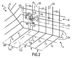
図2は、タンクの第1の壁1、タンクの第2の壁2、及びタンクの第3の壁3の間の密閉された密閉断熱タンクの角を示している。そのようなタンクは自立型であり、特に、平行六面体、角柱、球形、円筒形又は多重ローブの形をしていてもよい。 FIG. 2 shows the corners of a sealed closed insulated tank between a first wall 1 of the tank, a second wall 2 of the tank and a third wall 3 of the tank. Such tanks are self-supporting and may in particular have the shape of parallelepipeds, prisms, spheres, cylinders or multilobes.
第1の壁1と第3の壁3は、タンクの縦壁であり、一緒に135°の角度を形成する。さらに、第2の壁2は、第1の壁とともに、90°の角度を形成する。同様に、第2の壁2は第3の壁と90°の角度を形成する。 The first wall 1 and the third wall 3 are the vertical walls of the tank and together form an angle of 135°. Furthermore, the second wall 2 forms an angle of 90° with the first wall. Similarly, the second wall 2 forms a 90° angle with the third wall.
これらのタンク壁1、2及び3は、担持構造の平面担持壁に固定された断熱障壁と、断熱障壁によって担持される密閉膜と、場合によっては密閉膜に担持される1次断熱障壁と、1次断熱障壁に担持され液化天然ガス(LNG)などのタンクに含まれる極低温液体と接触するように設計された1次密閉膜と、を含む多層構造を有してもよい。これらのタンク壁1、2及び3は、例えば、図1を参照して上述したような標準化された要素を使用して製造される。従って、例えば、各タンク壁の2次及び1次断熱障壁は、WO2017/006044に記載されているように対応するタンク壁の中央部分から開始して並置された断熱ブロックから製造され得る。同様に、2次及び1次密閉膜は、密閉膜の負荷を吸収することを可能にする一連の垂直波形を有する標準化された金属シートを使用して製造されてもよい。一例として、絶縁パネル及び金属シートは、WO14057221又はFR2691520に記載されている対応する要素と同様の方法で製造することができる。 These tank walls 1, 2 and 3 comprise an insulating barrier fixed to the planar carrying wall of the carrying structure, a sealing membrane carried by the insulating barrier and possibly a primary insulating barrier carried by the sealing membrane, a primary sealing membrane carried by the primary insulating barrier and designed to contact a cryogenic liquid contained in the tank, such as liquefied natural gas (LNG). These tank walls 1, 2 and 3 are for example manufactured using standardized elements as described above with reference to FIG. Thus, for example, the secondary and primary insulation barriers of each tank wall may be manufactured from juxtaposed insulation blocks starting from the central portion of the corresponding tank wall as described in WO2017/006044. Similarly, the secondary and primary sealing membranes may be manufactured using standardized metal sheets with a series of vertical corrugations that allow them to absorb the load of the sealing membrane. By way of example, the insulating panels and metal sheets can be manufactured in a manner similar to the corresponding elements described in WO14057221 or FR2691520.
図2では、2次密閉膜のみが概略的に示されている。従って、図2は、第1のタンク壁1と第3のタンク壁3との間の接合部で2次密閉膜によって形成される稜線4、第1のタンク壁1と第2のタンク壁2間の接合部で2次密閉膜によって形成された稜線5、及び第2のタンク壁2と第3タンク壁3の間の接合部で2次密閉膜によって形成された稜線6を図示する。さらに、タンク内で縦方向に延びる波形のみが実線で示されており、これらの波形は、例えば、外側又は内側に向けられた様々な形状や異なる高さを有してよい。さらに、2次密閉膜のさまざまな要素間の溶接は、図2に破線の形で示されている。従って、この図2では、第2のタンク壁2の2枚の金属シート22、第1のタンク壁1と第2のタンク壁の金属連結ストリップ23、及び第1のタンク壁1と第2のタンク壁2の角金属シート24は破線で区切られている。
In FIG. 2 only the secondary sealing membrane is shown schematically. Thus, FIG. 2 shows the ridgeline 4 formed by the secondary sealing membrane at the junction between the first tank wall 1 and the third tank wall 3, the first tank wall 1 and the second tank wall 2. The
第1のタンク壁1及び第3のタンク壁3は、図1を参照して説明したタンク壁と同様の方法で形成することができる。従って、第1のタンク壁1の2次密閉膜は、稜線4に平行に、従って、稜線5に垂直に延びる一連の第1の波形7を有する。これらの波形7は、均等な分離間隔8で隔てられる。そのような均等な分離間隔8は例えば340mm程度である。さらに、第1のタンク壁1の2次密閉膜は、分離間隔80だけ稜線4から間隔を空けられた特有の波形9を含み、この分離間隔80は、例えば、均等な分離間隔8と同一又は異なることが可能である。この特有の波形9は、一連の第1の波形7の最後の波形10から、均等な分離間隔9とは異なる特有の分離間隔11だけ間隔が空けられている。この特有の分離間隔11は、例えば、340mmプラス又はマイナスのタンクの製造公差で決定される距離Xであり、この距離Xはタンクで異なる。この距離Xは、例えば40mm程度であり、それ以下でもよく、特有の分離間隔11は例えば340mmプラスマイナス40mmである。
The first tank wall 1 and the third tank wall 3 can be formed in a manner similar to the tank walls described with reference to FIG. The secondary sealing membrane of the first tank wall 1 thus has a series of first corrugations 7 extending parallel to the ridgeline 4 and thus perpendicular to the
同様に、第2のタンク壁2は、第1及び第3のタンク壁1、3と同様に形成されてもよい。従って、第2のタンク壁2の2次密閉膜は、均等な分離間隔8によって分離され稜線5に垂直な一連の第2の波形12を含む。第2のタンク壁2の2次密閉膜は、一連の第2の波形の波形12に垂直な、即ち稜線5に平行な一連の第3の波形13も含む。
Similarly, the second tank wall 2 may be formed similarly to the first and third tank walls 1,3. The secondary sealing membrane of the second tank wall 2 thus comprises a series of
稜線5で良好な柔軟性を提供するために、第1のタンク壁1の波形7、9は稜線5まで延長される。第1のタンク壁1の波形7、9は、好ましくは、タンクの稜線5に垂直な方向に測定された全長に亘って延びている。これらの波形7、9は、例えば、図1を参照して上述したように、90°の角度で第1のタンク壁1の角絶縁パネル(図示せず)によって担持される角金属シート24に存在する波形分によって延長される。
The corrugations 7 , 9 of the first tank wall 1 are extended up to the
さらに、タンクの組み立てを容易にするために、第1のタンク壁1の2次断熱障壁の断熱パネルの位置決めの基準として使用される第1のタンク壁1の中央部分も同様に第2のタンク壁の2次断熱障壁の断熱パネルの位置決めの基準として使用される。従って、2次密閉膜の一連の第1の波形7の波形7は、第2のタンク壁2の一連の第2の波形12の対応する波形と同一平面になるように配置される。
Moreover, for ease of tank assembly, the central portion of the first tank wall 1 used as a reference for the positioning of the insulation panels of the secondary insulation barrier of the first tank wall 1 is likewise the second tank. It is used as a reference for positioning the insulation panels of the secondary insulation barrier of the wall. Corrugations 7 of the series of first corrugations 7 of the secondary sealing membrane are thus arranged to be flush with corresponding corrugations of the series of
稜線5での2次密閉膜の良好な柔軟性を確保するために、一連の第1の波形7の波形7は、一連の第2の波形12の対応する波形12に連続的かつ密封的に接続される。典型的には、一連の第1の波形7の波形7と同一平面上にある一連の第2の波形12の波形12は、第2のタンク壁2の角金属シート24によって担持される波形分によって稜線5まで延びる。第1のタンク壁と第2のタンク壁の角金属シートの波形分は、図1を参照して上述した方法と同様の方法で、角金属シートを接続する角ブラケットに存在する波形によって一緒に接続される。従って、一連の第1の波形7の最後の波形10は、一連の第2の波形12の対応する波形14によって第2のタンク壁2上に延びている。
In order to ensure good flexibility of the secondary sealing membrane at the
ただし、図2に示すように、第2のタンク壁2は、第1のタンク壁1よりも長い距離に亘って、タンクの横方向、つまり稜線5に平行に延びている。確かに、第1のタンク壁1はこの方向で第3タンク壁3によって遮られるが、第2のタンク壁2はこの方向に続いて第2のタンク壁2と第3タンク壁3の間に90°の角度を形成する。従って、一連の第2の波形12の最後の波形15は、一連の第1の波形7の最後の波形10を均等な分離間隔8だけ延長する波形14から間隔が空けられている。実際、一連の第1の波形7の最後の波形10は、均等な分離間隔8とは異なる特有の分離間隔11だけ第1のタンク壁1の特有の波形9から間隔を空けられている。従って、第1のタンク壁1の特有の波形9と一連の第2の波形12の最後の波形15は同一平面上にない。従って、一連の第1の波形7の波形7を一連の第2の波形12の対応する波形12だけ延長するのと同様の方法では、第1のタンク壁の特有の波形9を一連の第2の波形12の最後の波形15だけ連続的かつ密封的に延長することはできない。
However, as shown in FIG. 2, the second tank wall 2 extends over a longer distance than the first tank wall 1 in the lateral direction of the tank, that is, parallel to the
稜線5で良好な柔軟性を提供するために、第1のタンク壁1の特有の波形9は、第2のタンク壁2の特有の波形16によって延長される。そのため、角ブラケットは、90°の角度に対して垂直で、第1のタンク壁1の特有の波形9を延ばす波形を有する。さらに、第2のタンク壁2の角金属シート24は、稜線5に垂直に延び、第1のタンク壁1の特有の波形9と同一平面にある特有の波形分17を有する。この特有の波形分17は、角ブラケットの波形を延長し、従って、第2のタンク壁2上の第1のタンク壁1の特有の波形9を連続かつ密封して延長する。
The characteristic corrugations 9 of the first tank wall 1 are extended by the
第2のタンク壁2の特有の波形16は、第1の閉鎖キャップ18をさらに備える。この第1の閉鎖キャップ18は、第2のタンク壁2の角金属シート24の特有の波形分17を伸ばして終端させる。
The
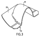
そのような閉鎖キャップ18は、種々の方法で製造することができる。従って、一実施形態による閉鎖キャップは、タンクの内部に向かって突出する特有の波形16の文脈内で図3に示される形態を有し得る。しかしながら、特有の波形16が別の幾何形状を有する場合、特有の波形16を閉じるために、閉鎖キャップ18の幾何形状は、結果として、例えば、タンク内の特有の波形の断面及び/又は配向と同一なタンク内の断面及び/又は配向を採用してもよい。
Such a
この第1の閉鎖キャップ18は、図3に示されるように、例えば重ね溶接によって密封固定される特有の波形分17を閉じる半ドームの形態の上部部分19を含む。固定板20は、上部19の基部を囲み、角金属シート24に隣接する金属シート22、典型的には第2のタンク壁の2次密閉膜の金属シートを角金属シート24に接続する金属連結ストリップ23上に密封して溶接される。固定板20は、有利には、固定板20を角金属シート24に重ね溶接するために、角金属シート24の方向にオフセットを含む。
This
第1のタンク壁1の特有の波形9が第2のタンク壁2の特有の波形16によって延長され、特有の波形16が稜線5からの距離において中断されることで、稜線5の2次密閉膜のための良好な柔軟性を維持することができる。この柔軟性は、タンクの稜線5において使用中に発生する熱応力と流体力学的及び静的荷重から生じる荷重が大きいため特に有利である。さらに、金属連結ストリップ23に溶接された第1の閉鎖キャップ18によって特有の波形16が中断されるので、同様にタンクでの使用中にストレスがかなりかかる角金属シート24を超えて特有の波形16が中断されることに関連する柔軟性の損失を相殺することを可能にする。さらに、第2のタンク壁2上の第1のタンク壁1の特有の波形9が延長されるので、第1のタンク壁1の特有の波形9が中断しないことが可能となる。長手方向のタンク壁、即ち、それらの間に135°の角度を形成するタンク壁は、使用中にかなりの負荷がかかるので、2次密閉膜が第1のタンク壁1の全長に亘って特有の波形9を持つことが特に有利である。
The characteristic corrugation 9 of the first tank wall 1 is extended by the
一連の第2の波形12の最後の波形15は、第2の閉鎖キャップ21によって中断される。この第2の閉鎖キャップ21は第1の閉鎖キャップ18に似ており、最後の波形15は稜線5から離れて中断される。第2の閉鎖キャップ21は、例えば金属連結ストリップ23に溶接されることにより最後の波形15を中断する。
The
均等な分離間隔8が特有の分離間隔11に近い場合、第1の閉鎖キャップ18及び第2の閉鎖キャップ21のそれぞれの固定プレートが重ね溶接されて、その結果、第2のタンクの最後の波形15及び特有の波形16が稜線5に可能な限り垂直な方向になり、それにより、第2のタンク壁2の2次密閉膜に良好な柔軟性を提供する。
If the uniform separation distance 8 is close to the characteristic separation distance 11, the respective fixing plates of the
第1の閉鎖キャップ18と第2の閉鎖キャップ21は簡単に製造できる部品である。さらに、これらのコンポーネントは、製造公差や特有の分離間隔11に関係なく標準化された方法で製造され、全てのタンクで使用される。従って、このような密閉断熱タンクは、タンクの製造公差から生じる予期できない側面にもかかわらず製造が簡単である。
The
上記の技術を使用して、単一の断熱障壁と単一の密閉膜を備えたタンクを製造したり、沿岸施設やメタン運搬船などの浮体構造で液化天然ガス(LNG)の2重膜タンクを構成したりできる。これに関連して、上記の図に示されている密閉膜は2次密閉膜とみなされ、図示されていない1次絶縁障壁と1次密閉膜もこの2次密閉膜に追加されると考えられる。このように、これらの技術は、複数の断熱障壁と密閉膜が重ねったタンクにも同様に適用できる。 The techniques described above can be used to fabricate tanks with a single insulating barrier and a single hermetic membrane, or double-membrane tanks for liquefied natural gas (LNG) in floating structures such as offshore facilities and methane carriers. can be configured. In this regard, the sealing membrane shown in the above figures is considered a secondary sealing membrane, and the primary insulating barrier and primary sealing membrane, not shown, are also considered to be added to this secondary sealing membrane. be done. Thus, these techniques are equally applicable to tanks with multiple insulating barriers and sealing membranes stacked on top of each other.
この後者の場合、2次密閉膜上にある1次断熱障壁、及び1次断熱障壁上にある1次密閉膜は、いくつかの方法で製造することができる。従って、1次断熱障壁は、2次密閉膜上に並置された断熱パネルを使用して、2次断熱障壁と同様の方法で製造され得る。同様に、1次密閉膜は、標準化された金属シートから製造されてもよい。 In this latter case, the primary insulating barrier overlying the secondary sealing membrane and the primary sealing membrane overlying the primary insulating barrier can be manufactured in several ways. Thus, the primary insulation barrier can be manufactured in a similar manner as the secondary insulation barrier using insulation panels juxtaposed over the secondary sealing membrane. Similarly, the primary sealing membrane may be manufactured from standardized metal sheets.
図4を参照すると、メタン運搬船70の切取図は、船舶の2重船体72に取り付けられた一般的な角柱形状の密閉断熱タンク71を示している。タンク71の壁は、タンクに含まれるLNGと接触するように設計された1次密閉障壁、1次密閉障壁と船舶の2重船体72との間に配置された2次密閉障壁、及び1次密閉障壁と2次密閉障壁、2次密閉障壁と2重船体72の間のそれぞれに配置された2つの断熱障壁を含む。
Referring to FIG. 4, a cutaway view of a
船舶の上部デッキに配置された積み上げ/積み下ろしパイプライン73は、それ自体知られている方法で、適切なコネクタを使用してLNGの貨物をタンク71から又はタンクに向かって輸送するための海上又は港湾ターミナルに接続されてもよい。
A loading/
図4は、積み上げ積み下ろしステーション75、水中ダクト76及び沿岸施設77からなる海上ターミナルの例を示している。積み上げ積み下ろしステーション75は、可動アーム74と、可動アーム74を担持するライザ78とを備える固定された沖合施設である。可動アーム74は、積み上げ/積み下ろしパイプライン73に接続することができる断熱された可撓性ホース79の束を担持する。向きを変えることができる可動アーム74は、全てのメタン運搬船のサイズに適合する。連結ダクト(図示せず)がライザ78の内部に延びている。積み上げ積み下ろしステーション75は、沿岸施設77から又は沿岸施設77に向かうメタン運搬船70の積み上げ積み下ろしを可能にする。沿岸施設は、液化ガスを貯蔵するタンク80、及び水中ダクト76によって積み上げ積み下ろしステーション75に接続されたダクト81を備える。水中ダクト76により、積み上げ又は積み上げ積み下ろしステーション75と沿岸施設77の間で、例えば5kmなどの長距離に亘って液化ガスを移動でき、これにより、メタン運搬船70が積み上げ及び積み下ろし中に海岸から遠く離れたままにあることを可能にする。
FIG. 4 shows an example of a marine terminal consisting of a loading and unloading
液化ガスの移送に必要な圧力を生成するために、船舶70に搭載されるポンプ及び/又は沿岸施設77に装備されるポンプ及び/又は積み上げ積み下ろしステーション75に装備されるポンプが実装される。
Pumps onboard the
本発明を複数の特定の実施形態に関連して説明したが、明らかにこれに限定されるものではなく、説明した手段の全ての技術的均等物及びこれらが本発明の文脈に含まれる場合はそれらの組み合わせも含む。 Although the invention has been described in connection with several particular embodiments, it is clearly not limited thereto but all technical equivalents of the means described and those included in the context of the invention. Including combinations thereof.
図示されていない一実施形態では、密閉断熱タンクは、例えば、図2を参照して上記で説明した2次断熱障壁及び2次密閉膜と同様の方法で製造された1つの断熱障壁及び1つの密閉膜のみを含む。 In one embodiment, not shown, the closed insulation tank comprises, for example, one insulation barrier and one Contains only the sealing membrane.
「構成される」又は「含む」の動詞及びその共役形の使用は、請求項に記載されているもの以外の要素又はステップの存在を排除するものではない。 Use of the verb "consist of" or "comprise" and its conjugations does not exclude the presence of elements or steps other than those stated in a claim.
特許請求の範囲では、括弧で囲まれた参照記号は請求の制限として解釈されるべきではない。 In the claims, any reference signs placed between parentheses shall not be construed as claim limitations.
Claims (14)
前記第1の担持壁に固定された第1のタンク壁(1)と、
前記第2の担持壁に固定された第2のタンク壁(2)と、を備え、
各タンク壁(1、2)が多層構造を有し、該多層構造が、前記密閉断熱タンクの外側から内側への厚さの方向に連続して、対応する前記担持壁に担持された断熱障壁、及び該断熱障壁によって担持された密閉膜を備え、
第1のタンク壁(1)の密閉膜が、前記稜線に垂直に延び前記稜線に沿って均等な分離間隔(8)だけ間隔を空けて配置された平行な一連の第1の波形(7、10)を含み、
第2のタンク壁の密閉膜(2)が、前記稜線に垂直に延び前記稜線に沿って前記均等な分離間隔(8)だけ間隔を空けて配置された平行な一連の第2の波形(12、14、15)を含み、
前記一連の第1の波形(7、10)の各波形(7、10)が、前記一連の第2の波形(12、14、15)の対応する波形(12、14)の延長上に配置され、
前記第1のタンク壁(1)の前記密閉膜が、前記一連の第1の波形(7、10)の波形(7、10)に平行に延びる特有の波形(9)をさらに含み、該特有の波形(9)が、前記一連の第1の波形(7、10)に隣接し、前記一連の第1の波形(7、10)の最後の波形(10)から前記均等な分離間隔(8)とは異なる特有の分離(11)だけ間隔を空けて配置され、
前記第2のタンク壁(2)の前記密閉膜が、前記一連の第2の波形(12、14、15)に平行で、前記第1のタンク壁(1)の前記特有の波形(9)の延長に位置する特有の波形(16)をさらに含み、前記第2のタンク壁(2)の前記特有の波形(16)が、前記稜線で前記第1のタンク壁(1)の前記特有の波形(9)に連続して接続され、前記第2のタンク壁(2)の前記特有の波形(16)が、前記第2のタンク壁(2)の一部に亘って延在し、前記稜線から離れた位置で前記第2のタンク壁(2)の前記特有の波形(16)を密閉して閉じる第1のリップル閉鎖キャップ(18)を含み、
前記一連の第2の波形(12、14、15)が、前記一連の第1の波形(7、10)の前記最後の波形(10)の対応する波形(14)、及び、前記一連の第2の波形(12、14、15)に属し前記特有の分離(11)により前記稜線の方向に前記第2のタンク壁(2)の前記特有の波形(16)からオフセットする最後の波形(15)を含み、前記一連の第2の波形(12、14、15)の前記最後の波形(15)が、前記一連の第2の波形(12、14、15)の前記最後の波形(15)を密閉して閉じる第2のリップル閉鎖キャップ(21)を含む、
密閉断熱タンク。 A closed and insulated tank incorporated in a carrier structure with a flat first carrier wall and a flat second carrier wall which together form a ridgeline of the carrier structure, comprising:
a first tank wall (1) fixed to said first carrier wall;
a second tank wall (2) secured to said second carrier wall;
Each tank wall (1, 2) has a multi-layered structure, said multi-layered structure being continuous in the direction of thickness from the outside to the inside of said closed and insulated tank, an insulating barrier carried on the corresponding said carrying wall. , and a sealing membrane carried by said insulating barrier;
The sealing membrane of the first tank wall (1) has a series of parallel first corrugations (7, 10) including
The sealing membrane (2) of the second tank wall has a series of parallel second corrugations (12) extending perpendicularly to said ridgeline and spaced along said ridgeline by said even separation distance (8). , 14, 15),
each waveform (7, 10) of said first series of waveforms (7, 10) being arranged in the extension of a corresponding waveform (12, 14) of said second series of waveforms (12, 14, 15); is,
Said sealing membrane of said first tank wall (1) further comprises characteristic corrugations (9) extending parallel to corrugations (7, 10) of said series of first corrugations (7, 10), said characteristic of waveforms (9) are adjacent to said series of first waveforms (7, 10) and are evenly spaced apart (8 ) and spaced apart by a unique separation (11),
said sealing membrane of said second tank wall (2) being parallel to said series of second corrugations (12, 14, 15) and said characteristic corrugations (9) of said first tank wall (1); wherein said characteristic corrugation (16) of said second tank wall (2) is aligned with said characteristic corrugation (16) of said first tank wall (1) at said ridge line Continuously connected to corrugations (9), said characteristic corrugations (16) of said second tank wall (2) extend over part of said second tank wall (2) and said a first ripple closure cap (18) sealingly closing said characteristic corrugation (16) of said second tank wall (2) at a location remote from the ridge;
The series of second waveforms (12, 14, 15) comprises the corresponding waveform (14) of the last waveform (10) of the series of first waveforms (7, 10) and the series of first waveforms (14). the last corrugation (15) belonging to two corrugations (12, 14, 15) and offset from said characteristic corrugation (16) of said second tank wall (2) in the direction of said ridge by said characteristic separation (11) ), wherein said last waveform (15) of said series of second waveforms (12, 14, 15) is said last waveform (15) of said series of second waveforms (12, 14, 15) a second ripple closure cap (21) sealingly closing the
closed insulated tank.
第1のタンク壁(1)の特有の波形(9)が前記第2の稜線に平行であり、
前記断熱障壁が、前記担持構造の前記第2の稜線に沿って前記担持構造の前記第2の稜線に平行な上部稜線(4)を形成し、
前記第1のタンク壁(1)の前記特有の波形(9)が、前記上部稜線(4)から所定の距離に配置される、請求項1~4の何れか一項に記載の密閉断熱タンク。 Said bearing structure comprises a flat third bearing forming with said flat first bearing wall a second ridge of said bearing structure parallel to said corrugations of said series of first corrugations (7, 10). including retaining walls,
the characteristic corrugation (9) of the first tank wall (1) is parallel to said second ridge,
said insulating barrier forms an upper edge (4) parallel to said second edge of said carrying structure along said second edge of said carrying structure;
A closed and insulated tank according to any one of claims 1 to 4, wherein said characteristic corrugation (9) of said first tank wall (1) is arranged at a predetermined distance from said upper ridge (4). .
前記担持構造を形成する2重船体(72)と、前記2重船体に配置された請求項1から11の何れか一項に記載の密閉断熱タンクとを含む船舶。 A vessel (70) for carrying a cryogenic liquid product, comprising:
A ship comprising a double hull (72) forming said supporting structure and a closed and insulated tank according to any one of claims 1 to 11 arranged in said double hull.
低温液体製品が、断熱パイプライン(73、79、76、81)を介して、沿岸又は沖合の貯蔵施設から又はそれらに向かって前記密閉断熱タンクに向かって又はそれから輸送される、
船舶の積み上げ積み下ろしの方法。 A method of loading and unloading a vessel according to claim 12, comprising:
Cryogenic liquid product is transported to or from said sealed insulated tanks from or to onshore or offshore storage facilities via insulated pipelines (73, 79, 76, 81).
The method of loading and unloading ships.
請求項12に記載の船舶と、
沿岸又は沖合の貯蔵施設(77)へ前記密閉断熱タンクを接続するように配置された断熱パイプラインと、
前記断熱パイプラインを通して沿岸又は沖合の貯蔵施設から又はそれに向かって前記密閉断熱タンクへ又はそれに向かって低温液体製品のフローを引き込むポンプと、を備える、輸送システム。 A transport system for cryogenic liquid products, comprising:
A ship according to claim 12;
an insulated pipeline arranged to connect said closed insulated tank to an onshore or offshore storage facility (77);
and a pump for drawing a flow of cryogenic liquid product from or towards an onshore or offshore storage facility through said insulated pipeline into or towards said closed insulated tank.
Applications Claiming Priority (3)
| Application Number | Priority Date | Filing Date | Title |
|---|---|---|---|
| FR1757556 | 2017-08-07 | ||
| FR1757556A FR3069903B1 (en) | 2017-08-07 | 2017-08-07 | SEALED AND THEMIALLY INSULATING TANK |
| PCT/FR2018/052023 WO2019030448A1 (en) | 2017-08-07 | 2018-08-03 | Sealed and thermally insulating tank |
Publications (3)
| Publication Number | Publication Date |
|---|---|
| JP2020530092A JP2020530092A (en) | 2020-10-15 |
| JP2020530092A5 JP2020530092A5 (en) | 2021-08-26 |
| JP7134222B2 true JP7134222B2 (en) | 2022-09-09 |
Family
ID=60382346
Family Applications (1)
| Application Number | Title | Priority Date | Filing Date |
|---|---|---|---|
| JP2020506807A Active JP7134222B2 (en) | 2017-08-07 | 2018-08-03 | Hermetically sealed insulated tank |
Country Status (8)
| Country | Link |
|---|---|
| EP (1) | EP3665414B1 (en) |
| JP (1) | JP7134222B2 (en) |
| KR (1) | KR102504563B1 (en) |
| CN (1) | CN111108322B (en) |
| ES (1) | ES2869236T3 (en) |
| FR (1) | FR3069903B1 (en) |
| RU (1) | RU2764605C2 (en) |
| WO (1) | WO2019030448A1 (en) |
Families Citing this family (1)
| Publication number | Priority date | Publication date | Assignee | Title |
|---|---|---|---|---|
| FR3099946B1 (en) | 2019-08-12 | 2021-07-09 | Gaztransport Et Technigaz | Sealed and thermally insulating tank |
Citations (4)
| Publication number | Priority date | Publication date | Assignee | Title |
|---|---|---|---|---|
| JP2005121229A (en) | 2003-10-16 | 2005-05-12 | Gaz Transport & Technigaz | Sealed wall structure and tank to be installed in the same |
| US20090293506A1 (en) | 2008-05-30 | 2009-12-03 | Daewoo Shipbuilding & Marine Engineering Co., Ltd. | Semi-Submersible Offshore Structure Having Storage Tanks for Liquified Gas |
| US20150176765A1 (en) | 2012-09-21 | 2015-06-25 | Woodside Energy Technologies Pty Ltd. | Integrated storage/offloading facility for an lng production plant |
| JP2016515986A (en) | 2013-04-11 | 2016-06-02 | ギャズトランスポルト エ テクニギャズ | Impermeable barrier corrugation uncoupling |
Family Cites Families (13)
| Publication number | Priority date | Publication date | Assignee | Title |
|---|---|---|---|---|
| JPS56109993A (en) * | 1980-02-05 | 1981-08-31 | Ishikawajima Harima Heavy Ind Co Ltd | Expansion joint used in fluid storing tank at corner part of its side wall |
| SU1432307A1 (en) * | 1987-01-19 | 1988-10-23 | Всесоюзный Научно-Исследовательский И Проектный Институт "Теплопроект" | Thermal insulation structure of isothermic reservoir |
| FR2691520B1 (en) | 1992-05-20 | 1994-09-02 | Technigaz Ste Nle | Prefabricated structure for forming watertight and thermally insulating walls for containment of a fluid at very low temperature. |
| FR2780942B1 (en) * | 1998-07-10 | 2000-09-08 | Gaz Transport & Technigaz | WATERPROOF AND THERMALLY INSULATING TANK WITH IMPROVED ANGLE STRUCTURE, INTEGRATED INTO A SHIP-CARRIED STRUCTURE |
| RU30731U1 (en) * | 2002-10-07 | 2003-07-10 | Общество с ограниченной ответственностью "Многопрофильное предприятие "Азовмашпром" | STORAGE FOR LIQUIDS |
| FR2961580B1 (en) * | 2010-06-17 | 2012-07-13 | Gaztransport Et Technigaz | WATERPROOF AND INSULATED TANK WITH SUPPORT FOOT |
| FR2978748B1 (en) * | 2011-08-01 | 2014-10-24 | Gaztransp Et Technigaz | SEALED AND THERMALLY INSULATED TANK |
| FR2983751B1 (en) * | 2011-12-08 | 2014-08-08 | Gaztransp Et Technigaz | CONSTRUCTION OF A SEALED MEMBRANE FROM METAL PLATES |
| FR2996520B1 (en) | 2012-10-09 | 2014-10-24 | Gaztransp Et Technigaz | SEALED AND THERMALLY INSULATING TANK COMPRISING A METALIC MEMBRANE WOUNDED ACCORDING TO ORTHOGONAL PLATES |
| KR101625877B1 (en) * | 2014-07-16 | 2016-06-01 | 삼성중공업 주식회사 | Cargo for liquefied gas and manufacturing method thereof |
| FR3038690B1 (en) | 2015-07-06 | 2018-01-05 | Gaztransport Et Technigaz | THERMALLY INSULATING, WATERPROOF TANK WITH SECONDARY SEALING MEMBRANE EQUIPPED WITH ANGLE ARRANGEMENT WITH WALL-MOLDED METAL SHEETS |
| RU2600419C1 (en) * | 2015-08-13 | 2016-10-20 | Общество с ограниченной ответственностью проектно-конструкторское бюро "БАЛТМАРИН" | Membrane tank for liquefied natural gas (vm type) |
| KR101826684B1 (en) * | 2015-10-12 | 2018-02-07 | 대우조선해양 주식회사 | Membraine type lng storage tank |
-
2017
- 2017-08-07 FR FR1757556A patent/FR3069903B1/en not_active Expired - Fee Related
-
2018
- 2018-08-03 EP EP18762375.6A patent/EP3665414B1/en active Active
- 2018-08-03 CN CN201880051734.9A patent/CN111108322B/en active Active
- 2018-08-03 KR KR1020207005526A patent/KR102504563B1/en active IP Right Grant
- 2018-08-03 JP JP2020506807A patent/JP7134222B2/en active Active
- 2018-08-03 RU RU2020102710A patent/RU2764605C2/en active
- 2018-08-03 ES ES18762375T patent/ES2869236T3/en active Active
- 2018-08-03 WO PCT/FR2018/052023 patent/WO2019030448A1/en unknown
Patent Citations (4)
| Publication number | Priority date | Publication date | Assignee | Title |
|---|---|---|---|---|
| JP2005121229A (en) | 2003-10-16 | 2005-05-12 | Gaz Transport & Technigaz | Sealed wall structure and tank to be installed in the same |
| US20090293506A1 (en) | 2008-05-30 | 2009-12-03 | Daewoo Shipbuilding & Marine Engineering Co., Ltd. | Semi-Submersible Offshore Structure Having Storage Tanks for Liquified Gas |
| US20150176765A1 (en) | 2012-09-21 | 2015-06-25 | Woodside Energy Technologies Pty Ltd. | Integrated storage/offloading facility for an lng production plant |
| JP2016515986A (en) | 2013-04-11 | 2016-06-02 | ギャズトランスポルト エ テクニギャズ | Impermeable barrier corrugation uncoupling |
Also Published As
| Publication number | Publication date |
|---|---|
| ES2869236T3 (en) | 2021-10-25 |
| JP2020530092A (en) | 2020-10-15 |
| WO2019030448A1 (en) | 2019-02-14 |
| FR3069903A1 (en) | 2019-02-08 |
| RU2764605C2 (en) | 2022-01-18 |
| FR3069903B1 (en) | 2019-08-30 |
| EP3665414A1 (en) | 2020-06-17 |
| CN111108322A (en) | 2020-05-05 |
| KR102504563B1 (en) | 2023-02-28 |
| KR20200037304A (en) | 2020-04-08 |
| RU2020102710A (en) | 2021-09-10 |
| CN111108322B (en) | 2022-03-01 |
| EP3665414B1 (en) | 2021-03-24 |
| RU2020102710A3 (en) | 2021-12-06 |
Similar Documents
| Publication | Publication Date | Title |
|---|---|---|
| CN107820554B (en) | Sealed and thermally insulated tank equipped with a corner-arranged secondary sealing membrane of corrugated metal sheet | |
| US9677711B2 (en) | Sealed and thermally insulating tank for storing a fluid | |
| CN107289319B (en) | Sealed pot with corrugated sealing film | |
| KR102029862B1 (en) | Vessel wall comprising a pipe | |
| KR102413578B1 (en) | Corner structure for a leaktight and thermally insulating tank | |
| JP7229259B2 (en) | Equipment for storing and transporting liquefied gas | |
| KR102498803B1 (en) | sealed and insulated tank | |
| CN109790958B (en) | Leakage-proof wall structure | |
| KR102501626B1 (en) | sealed and insulated tank | |
| KR20210141525A (en) | Insulated sealed tank | |
| KR102657084B1 (en) | Rigid tank walls with sealing membrane | |
| JP7134222B2 (en) | Hermetically sealed insulated tank | |
| KR20220125329A (en) | Liquefied gas storage facility | |
| CN114746690B (en) | Sealed and insulated tanks, systems and vessels and methods of loading or unloading same | |
| KR20230012570A (en) | Liquefied gas storage facility | |
| JP6228709B1 (en) | Sealed insulation tank | |
| CN112368506A (en) | Liquid-tight container provided with corrugated engagement elements | |
| RU2767850C2 (en) | Sealing membrane and method for assembly of sealing membrane | |
| KR102473428B1 (en) | Connecting beams for thermally insulated sealing tanks for storing liquefied gas | |
| JP2023544598A (en) | Methods for assembling and installing liquefied gas storage tanks | |
| KR20230098056A (en) | Storage facility for liquefied gas | |
| KR20220090447A (en) | Ship including a tank | |
| KR20210083326A (en) | liquefied gas storage facility |
Legal Events
| Date | Code | Title | Description |
|---|---|---|---|
| A521 | Request for written amendment filed |
Free format text: JAPANESE INTERMEDIATE CODE: A523 Effective date: 20210714 |
|
| A621 | Written request for application examination |
Free format text: JAPANESE INTERMEDIATE CODE: A621 Effective date: 20210714 |
|
| A131 | Notification of reasons for refusal |
Free format text: JAPANESE INTERMEDIATE CODE: A131 Effective date: 20220405 |
|
| A601 | Written request for extension of time |
Free format text: JAPANESE INTERMEDIATE CODE: A601 Effective date: 20220704 |
|
| A521 | Request for written amendment filed |
Free format text: JAPANESE INTERMEDIATE CODE: A523 Effective date: 20220712 |
|
| TRDD | Decision of grant or rejection written | ||
| A01 | Written decision to grant a patent or to grant a registration (utility model) |
Free format text: JAPANESE INTERMEDIATE CODE: A01 Effective date: 20220802 |
|
| A61 | First payment of annual fees (during grant procedure) |
Free format text: JAPANESE INTERMEDIATE CODE: A61 Effective date: 20220830 |
|
| R150 | Certificate of patent or registration of utility model |
Ref document number: 7134222 Country of ref document: JP Free format text: JAPANESE INTERMEDIATE CODE: R150 |