JP7128329B2 - CRANE OPERATION ASSISTANCE SYSTEM AND CRANE OPERATION ASSISTANCE METHOD - Google Patents
CRANE OPERATION ASSISTANCE SYSTEM AND CRANE OPERATION ASSISTANCE METHOD Download PDFInfo
- Publication number
- JP7128329B2 JP7128329B2 JP2021112114A JP2021112114A JP7128329B2 JP 7128329 B2 JP7128329 B2 JP 7128329B2 JP 2021112114 A JP2021112114 A JP 2021112114A JP 2021112114 A JP2021112114 A JP 2021112114A JP 7128329 B2 JP7128329 B2 JP 7128329B2
- Authority
- JP
- Japan
- Prior art keywords
- container
- drone
- control
- camera
- crane
- Prior art date
- Legal status (The legal status is an assumption and is not a legal conclusion. Google has not performed a legal analysis and makes no representation as to the accuracy of the status listed.)
- Active
Links
Images


Landscapes
- Control And Safety Of Cranes (AREA)
- Traffic Control Systems (AREA)
- Control Of Position, Course, Altitude, Or Attitude Of Moving Bodies (AREA)
Description
本発明はクレーンオペレータが行うコンテナ荷役作業を補助するクレーン運転補助システムおよびクレーン運転補助方法に関するものであり、詳しくは作業員の接近が困難な場所であっても荷役対象のコンテナおよびコンテナ載置面の状況をクレーンオペレータが確認することができるクレーン運転補助システムおよびクレーン運転補助方法に関するものである。
BACKGROUND OF THE
コンテナを荷役するコンテナクレーンの操作を補助するクレーン補助システムが提案されている(たとえば特許文献1参照)。
A crane assist system has been proposed that assists the operation of a container crane that loads and unloads containers (see
特許文献1は、荷役対象のコンテナの周囲で作業を行なう作業員に設置するカメラと、コンテナクレーンの運転室に設置されてこのカメラで取得される画像を表示するモニタとを備えるクレーン運転補助システムを提案する。このスプレッダに吊り下げられたコンテナがコンテナ載置面に着床する際に、このコンテナやコンテナ載置面の側面の画像を確認しながらクレーンオペレータはコンテナクレーンの操作を行なうことができていた。
たとえば作業員のいる位置からコンテナが二段積み重ねられていて、さらに三段目にコンテナを積む際には、コンテナ載置面が作業員のいる位置から5m以上の高さとなる。三段目となるコンテナの側面を作業員のカメラで撮影すると、低い位置から見上げた状態となっていた。そのため二段目のコンテナと三段目のコンテナとの間の距離である高さ方向の情報を、カメラの画像からクレーンオペレータが読み取るのは困難であった。 For example, when two containers are stacked from the worker's position, and the container is stacked on the third tier, the height of the container mounting surface is 5 m or more from the worker's position. When the side of the third tier container was photographed by the worker's camera, it was seen looking up from a low position. Therefore, it was difficult for the crane operator to read information in the height direction, which is the distance between the second-tier container and the third-tier container, from the camera image.
本発明は上記の問題を鑑みてなされたものであり、その目的は作業員の接近が困難な場所であっても荷役対象のコンテナおよびコンテナ載置面の状況をクレーンオペレータが確認することができるクレーン運転補助システムおよびクレーン運転補助方法を提供することにある。 SUMMARY OF THE INVENTION The present invention has been made in view of the above problems, and its object is to enable a crane operator to check the condition of a container to be handled and the container mounting surface even in a place that is difficult for workers to access. An object of the present invention is to provide a crane operation assistance system and a crane operation assistance method.
上記の目的を達成するクレーン運転補助システムは、コンテナクレーンのスプレッダにより荷役されるコンテナを撮影するカメラと、前記コンテナクレーンの運転室に設置されて前記カメラによる撮影画像が表示されるモニタとを備えたクレーン運転補助システムにおいて、周囲との距離を測定する複数の距離センサと前記カメラとが設置されるドローンとこのドローンを制御する制御機構とを備えていて、荷役対象の前記コンテナが載置されるコンテナ載置面の近傍に前記ドローンを待機させて、荷役対象の前記コンテナの側面を前記ドローンの前記カメラで撮影させる撮影制御と、前記距離センサに周囲の障害物までの距離を測定させてこの距離が所定の値よりも小さくならない状態に前記ドローンの位置を制御する衝突防止制御とを行なう構成を前記制御機構が有していて、前記制御機構が撮影制御と衝突防止制御とを同時並行で行う構成を有することを特徴とする。 A crane operation assistance system for achieving the above object comprises a camera for photographing a container being loaded and unloaded by a spreader of a container crane, and a monitor installed in the operator's cab of the container crane for displaying an image photographed by the camera. The crane operation assistance system includes a drone in which a plurality of distance sensors for measuring the distance to the surroundings and the camera are installed, and a control mechanism for controlling the drone, and the container to be loaded and unloaded is placed. The drone is made to stand by in the vicinity of the container mounting surface, and the camera of the drone photographs the side surface of the container to be loaded and unloaded , and the distance sensor is caused to measure the distance to surrounding obstacles. The control mechanism has a configuration for performing anti-collision control for controlling the position of the drone in a state in which the distance does not become smaller than a predetermined value, and the control mechanism simultaneously performs shooting control and anti-collision control. It is characterized by having a configuration performed by
上記の目的を達成するクレーン運転補助方法は、コンテナクレーンのスプレッダにより荷役されるコンテナをカメラで撮影して、この撮影画像を前記コンテナクレーンの運転室のモニタに表示するクレーン運転補助方法において、周囲との距離を測定する複数の距離センサと前記カメラとをドローンに設置して、荷役対象の前記コンテナが載置されるコンテナ載置面の近傍に前記ドローンを待機させて、荷役対象の前記コンテナの側面を前記ドローンの前記カメラで撮影させる撮影制御と、前記距離センサに周囲の障害物までの距離を測定させてこの距離が所定の値よりも小さくならない状態に前記ドローンの位置を制御する衝突防止制御とを行う構成を有するとともに、撮影制御と衝突防止制御とを同時並行で行う構成を有することを特徴とする。 A crane operation assistance method for achieving the above object is a crane operation assistance method in which a container being unloaded by a spreader of a container crane is photographed by a camera, and the photographed image is displayed on a monitor in the operator's cab of the container crane. A plurality of distance sensors for measuring the distance to and the camera are installed in a drone, the drone is made to stand by in the vicinity of the container mounting surface on which the container to be handled is mounted, and the container to be handled a photographing control for photographing the side of the drone with the camera of the drone; prevention control, and a configuration for performing shooting control and collision prevention control in parallel .
本発明によれば、カメラがドローンに設置されているので、作業員の接近が困難な高所であっても荷役対象のコンテナの側面をカメラで撮影できる。荷役対象のコンテナおよびコンテナ載置面の状況を、クレーンオペレータが正確に確認するには有利である。 According to the present invention, since the camera is installed in the drone, the side surface of the container to be handled can be photographed by the camera even at a high place that is difficult for workers to approach. It is advantageous for the crane operator to accurately check the condition of the container to be handled and the container mounting surface.
以下、本発明のクレーン運転補助システムおよびクレーン運転補助方法を図に示した実施形態に基づいて説明する。図中では載置されるコンテナの長手方向を矢印y、コンテナの短手方向を矢印x、上下方向を矢印zで示している。 BEST MODE FOR CARRYING OUT THE INVENTION A crane operation assistance system and a crane operation assistance method of the present invention will be described below based on embodiments shown in the drawings. In the drawing, the longitudinal direction of the container to be placed is indicated by an arrow y, the lateral direction of the container is indicated by an arrow x, and the vertical direction is indicated by an arrow z.
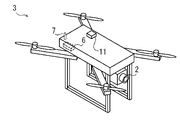
図1に例示するように本発明のクレーン運転補助システム1は、例えば岸壁クレーンや門型クレーンなどのコンテナクレーンに設置されて、クレーンオペレータによるコンテナクレーンの操作を補助する。クレーン運転補助システム1は、カメラ2が設置されるドローン3と、このカメラ2で撮影される撮影画像を表示するモニタ4とを備えている。本明細書においてドローン3は、自動制御または遠隔操縦にて飛行可能に構成される無人航空機を意味する。
As illustrated in FIG. 1, a crane
モニタ4は、岸壁クレーンなどのコンテナクレーンの運転室5に設置される。コンテナクレーンがクレーンオペレータにより遠隔で操作される場合は、遠隔操作のためのコントローラ等が配置される管理棟などに運転室5が設置される。図1では説明のため運転室5を破線で示している。
A
図2に例示するようにドローン3は、カメラ2と、ドローン3の飛行を制御したりカメラ2の動作を制御したりする制御機構6を備えている。図2では説明のため制御機構6を破線で示している。この制御機構6はドローン3に設置される構成に限定されず、ドローン3の外部に制御機構6が設置される構成としてもよい。
As illustrated in FIG. 2 , the
ドローン3は通信機構7を備えている。通信機構7は、カメラ2で撮影する画像をモニタ4に送信する機能を有している。モニタ4は送られてくる画像のデータを受信する機能を有している。制御機構6がドローン3の外部に設置される場合は、ドローン3を制御するための制御信号が制御機構6から送信されてこの通信機構7で受信される構成にしてもよい。
The
岸壁クレーン等のコンテナクレーンは、コンテナをコンテナ船に積み込む作業を行なう。図1に例示するようにコンテナクレーンは、スプレッダ8で吊り下げた荷役対象のコンテナ9を、他のコンテナ9の上に積み上げていく。荷役対象のコンテナ9を載置する面をコンテナ載置面10ということがある。図1では既に載置されているコンテナ9の上面がコンテナ載置面10となる。コンテナ船の船倉やコンテナヤードの地面に荷役対象のコンテナ9を載置する場合は、これらの面がコンテナ載置面10となる。
A container crane, such as a quayside crane, performs the work of loading containers onto a container ship. As illustrated in FIG. 1 , the container
作業員は遠隔操作によりコンテナ載置面10の近傍にドローン3を移動させる。ドローン3に設置されるカメラ2がコンテナ載置面10の方向を向く状態に、作業員はドローン3の向きを調整する。その後、作業員はスイッチ等の操作により、ドローン3の移動が完了した旨の信号を制御機構6に伝える。制御機構6は移動を完了したドローン3を待機させる。
The worker moves the
制御機構6は、待機中のドローン3の位置およびカメラ2の向きを維持する制御を行なうとともに、コンテナ載置面10および荷役対象のコンテナ9の側面をカメラ2で撮影する。カメラ2で撮影する画像をモニタ4に表示させるために、制御機構6は画像のデータを通信機構7からモニタ4に送信する。制御機構6によるこれらの制御を以下、撮影制御ということがある。撮影制御のときドローン3の上下方向zの位置がコンテナ載置面10と同じ高さか若干高い位置となる状態に、制御機構6がドローン3を制御する。
The
撮影制御の際には、ドローン3はホバリング状態となる。またカメラ2の方向をコンテナ載置面10に向ける姿勢の制御も同時に行われる。ドローン3が複数のカメラ2を有していて、コンテナ載置面10とは異なる方向を別のカメラ2で並行して撮影する構成にしてもよい。これによりドローン3の周囲の状況をモニタ4に表示できる。クレーンオペレータは荷役対象のコンテナ9の状況の他にドローン3の周囲の状況を確認することができるので、コンテナ9を荷役する際の操作の安全性を向上するには有利である。
During shooting control, the
本発明は撮影制御の際にドローン3がホバリング状態で撮影を行なう構成に限定されない。周辺の他のコンテナ9などの構造物にドローン3を着陸させた状態で、荷役対象のコンテナ9の側面およびコンテナ載置面10の側面をカメラ2で撮影する構成にしてもよい。ドローン3が着陸可能な構造物の存在が条件となるが、カメラ2の位置を固定状態とすることができるので安定した画像をモニタ4に表示することができる。またドローン3の消費電力を抑制できる。
The present invention is not limited to the configuration in which the
図3に例示するようにクレーンオペレータは、コンテナ載置面10と荷役対象のコンテナ9との側面の状況をモニタ4で確認しながら、スプレッダ8を降下させることができる。クレーンオペレータは、荷役対象のコンテナ9の真横からの画像を確認しつつ荷役作業を行えるので、このコンテナ9がコンテナ載置面10に着床するまでの距離を正確に把握することができる。つまりクレーンオペレータは上下方向zの正確な情報を得ることができる。コンテナ9がコンテナ載置面10に衝突するなどの不具合を回避するには有利である。
As illustrated in FIG. 3 , the crane operator can lower the
本発明によれば作業員の接近が困難な場所においても、荷役対象のコンテナ9およびコンテナ載置面10の周囲の状況をドローン3のカメラ2で撮影して、モニタ4に表示することができる。そのためクレーンオペレータは、コンテナ載置面10の位置に関わらず、モニタ4に表示される画像から荷役対象のコンテナ9およびコンテナ載置面10の状況を確認することができる。
According to the present invention, the
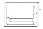
図4に例示するようにたとえばコンテナ載置面10が二段目のコンテナ9の上面であり、三段目となる位置に荷役対象のコンテナ9を載置する場合がある。従来のように作業員に設置されるカメラでコンテナ9を撮影すると下方から見上げる状態となるため、荷役対象のコンテナ9とコンテナ載置面10と間の距離など、上下方向zの情報を十分に確認できる画像をモニタに表示できなかった。
As illustrated in FIG. 4, for example, the
これに対して本発明では飛行可能なドローン3にカメラ2を設置する構成により、荷役対象のコンテナ9をカメラ2で真横から撮影してモニタ4に表示することができる。クレーンオペレータがモニタ4に表示される画像から上下方向zの正確な情報を得るとともに、クレーンオペレータがコンテナ9を正しい位置に着床させるクレーン操作を行うには極めて有利である。図4では説明のためドローン3に設置されるカメラ2の視野の範囲と、作業員に設置されるカメラの視野の範囲とを破線で示している。
On the other hand, according to the present invention, by installing the
図2に例示するようにドローン3が、自身の位置情報を取得する位置情報取得機構11を備える構成にしてもよい。位置情報取得機構11は、ドローン3が自身の位置を把握できる構成を有していればよい。位置情報取得機構11は、たとえばGPSや準天頂衛星などの衛星測位システムや、コンテナヤードやコンテナ船に複数のトランスポンダを配置してこのトランスポンダとの相対位置を超音波や電波を利用して測定する装置などで構成することができる。
As illustrated in FIG. 2, the
ここでトランスポンダとは、ドローン3に設置される位置情報取得機構11との間で信号の送受信を行える機器であり、それぞれのトランスポンダは設置される場所の位置情報を有している。これによりドローン3の位置情報取得機構11は所定のトランスポンダとの相対位置とトランスポンダの位置情報とからドローン3の位置を取得することができる。つまりドローン3は、位置情報取得機構11により自身の位置座標や高度を位置情報として取得することができる。
Here, the transponder is a device capable of transmitting and receiving signals to and from the position
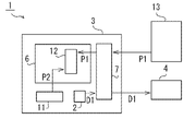
ドローン3が位置情報取得機構11を有する場合、図5に例示するように制御機構6がコンテナ載置面10の位置情報P1とドローン3の位置情報P2とを取得する取得部12を備える構成にしてもよい。コンテナ載置面10の位置座標や高度を示す位置情報P1は、たとえばコンテナヤードで複数のコンテナ9の識別情報や行き先情報を管理する管理システム13から、通信機構7を介して制御機構6は取得することができる。管理システム13はコンテナヤードの例えば管理棟などに設置されていて、少なくともコンテナ載置面10の位置情報が格納されている。また管理システム13は、クレーンオペレータが作業しているコンテナ9がいずれの場所のコンテナ載置面10に載置されるべきであるかの情報を有している。クレーンオペレータは管理システム13からの情報にもとづき、荷役対象のコンテナ9を指示される場所に載置していく。
When the
この構成によれば制御機構6は、コンテナ載置面10の位置情報P1とドローン3の位置情報P2とを比較することにより、ドローン3をコンテナ載置面10の近傍まで自動で移動させることができる。この制御機構6による制御を以下、移動制御ということがある。制御機構6は移動制御によりドローン3を自動で移動させる。荷役対象のコンテナ9が載置される予定のコンテナ載置面10の近傍にドローン3が到着した後に、制御機構6は撮影制御を行なう。カメラ2で撮影される画像の画像データD1は通信機構7を介してモニタ4に送信される。
According to this configuration, the
制御機構6の移動制御によりドローン3を自動的に所定の位置まで移動させることができるので、ドローン3を操作するための作業員が不要となる。作業員は別の作業を行なうことができるので、コンテナ9の荷役の作業効率を向上するには有利である。
Since the
たとえば管理システム13の内部など、ドローン3の外部に制御機構6が配置されている場合には、制御機構6の取得部12は管理システム13からコンテナ載置面10の位置情報P1を取得するとともに、通信機構7を介してドローン3の位置情報P2を取得する。これらの位置情報P1、P2に基づいてドローン3が移動すべき方向や距離を制御機構6が決定して、これらを制御信号として制御機構6からドローン3に送信することで移動制御を行う構成としてもよい。
For example, when the
岸壁クレーン等のコンテナクレーンで、コンテナ船からコンテナの荷降ろしをする場合には、スプレッダ8のみをコンテナ9に向けて降下させ、そのコンテナ9をスプレッダ8で掴んでコンテナ船から運び出す。スプレッダ8は荷役対象のコンテナ9の上面への着床を検知するリミットスイッチ等を備えている。そのためドローン3を備えるクレーン運転補助システム1を利用しなくても、コンテナ9の荷降ろしは比較的効率よく行なうことができる。
When a container crane such as a wharf crane is used to unload a container from a container ship, only the
しかしながらクレーン運転補助システム1を利用して、コンテナ9の上面にスプレッダ8を降下させる構成にしてもよい。ここで荷役対象のコンテナ9の上面は、前述のコンテナ載置面10に相当する面である。このときドローン3のカメラ2は、スプレッダ8の側面とコンテナ載置面10の側面とを撮影してモニタ4に表示する。クレーンオペレータは、スプレッダ8がコンテナ載置面10に着床するまでの上下方向zの距離をモニタ4で確認しながら、スプレッダ8を降下させることができる。スプレッダ8の降下速度が早すぎてコンテナ載置面10に衝突する不具合を回避するには有利である。
However, the crane
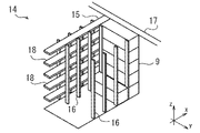
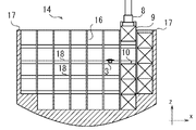
図6に例示するようにコンテナ船14は、コンテナ船14の前後方向(長手方向y)で船倉を区切る隔壁15を備えている。図6に例示する実施形態ではコンテナ9の長手方向yがコンテナ船14の前後方向と平行となる状態であり、短手方向xがコンテナ船14の幅方向と平行となる状態でコンテナ9が船倉に載置されている。隔壁15にはコンテナ船14の幅方向(短手方向x)に間隔を開けて複数のセルガイド16が設置されている。セルガイド16は、コンテナ9の搬入及び搬出の際にコンテナ9をガイドする部材である。またセルガイド16は、コンテナ船14の航海中にコンテナ9を保持する機能も有している。そのため一般的にコンテナ船14の船倉の中に配置されるコンテナ9は、連結金具や固縛具により固定する必要がない。
As illustrated in FIG. 6 , the
隔壁15は、短手方向xにおいて船倉の内部の一端から他端に延設されるとともに、上下方向zにおいて船倉の底から甲鈑17まで延設される。隔壁15の内部には作業員が短手方向xに移動するための通路18が形成されている。この通路18には図示していないが階段が設置されていて、作業員は上下方向zにも移動することができる。
The
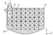
図6および図7に例示するように、岸壁クレーン等のコンテナクレーンによりコンテナ船14にコンテナ9を積み込む際には、コンテナ9を上下方向zに続けて積み上げていく場合がある。図7に例示するようにコンテナ9が高く積み上げられる状態であっても、ドローン3は荷役対象のコンテナ9の側面およびコンテナ載置面10の側面を撮影することができる。作業員にカメラを設置した場合では得られない画像をドローン3は撮影することができる。なお図7はコンテナ船14において幅方向(短手方向x)と平行となる断面を示している。
As illustrated in FIGS. 6 and 7, when loading the
船倉の中ではコンテナ9はセルガイド16により保持されるので、コンテナ9を固定するための作業が不要となる。コンテナ9を積み込む際に船倉の中で作業員が行なうべき作業はほとんどない。ドローン3を利用することにより、船倉の中にコンテナ9を積み込む際に作業員は別の場所での作業を行なうことができる。コンテナ9の荷役作業における省人化には有利である。
Since the
ドローン3を船倉の中で飛行させる際には、ドローン3は風の影響をほとんど受けない。そのためクレーン運転補助システム1は、安定して必要な画像をモニタ4に表示することができる。甲鈑17の上にコンテナ9を積む際にドローン3を利用してもよいが、船倉の中でのみドローン3が作業を行なう構成にしてもよい。この場合、制御機構6がドローン3の高度を監視して、甲鈑17よりも低い範囲でのみドローン3を飛行させる制御を行ってもよい。制御機構6によるこの制御を以下、空域制限制御ということがある。
When flying the
制御機構6が空域制限制御を行っているときは、ドローン3は甲鈑17よりも高い位置に侵入することを制限される。またドローン3が甲鈑17よりも高い位置を飛行している場合は、制御機構6はドローン3を降下させる制御を行なう。ドローン3が作業員の遠隔操作により移動する場合であっても、制御機構6の移動制御により移動する場合であっても、空域制限制御を行うことができる。
When the
制御機構6が空域制限制御を行っている場合であって、甲鈑17よりも高い位置でコンテナ9を積み込む作業を行なう際には、作業員に設置したカメラの画像をモニタ4に表示する構成にしてもよい。たとえば管理システム13から取得するコンテナ載置面10の位置情報P1が、甲鈑17よりも高い位置であった場合、制御機構6はドローン3の移動制御を行わない構成としてもよい。この場合、クレーン運転補助システム1がモニタ4の画像をドローン3のカメラ2から作業員のカメラに自動で切り替える制御を行ってもよい。
When the
図8に例示するように隔壁15の通路18の中でドローン3を飛行させてもよい。制御機構6が撮影制御を行なう際、コンテナ9の短手方向xの側面を撮影する。制御機構6によるこの撮影制御を以下、特に短手方向撮影制御ということがある。これに対してコンテナ9の長手方向yの側面を撮影する撮影制御を以下、特に長手方向撮影制御ということがある。
The
図9に例示するようにコンテナ載置面10が、積み上げられた他のコンテナ9とコンテナ船14の側壁19とで囲まれる場合がある。この場合コンテナ載置面10の長手方向yの側面はコンテナ9と側壁19とで囲まれるため、ドローン3が侵入できない。そのため制御機構6が撮影制御を行なう際に長手方向撮影制御を行なうことができない。このような場合には図8に例示するようにドローン3を通路18に侵入させて、コンテナ載置面10の短手方向xの側面を撮影させることができる。
As illustrated in FIG. 9 , the
コンテナ載置面10の位置情報P1に応じて、長手方向撮影制御または短手方向撮影制御のいずれかを選択する選択制御を行なう構成を制御機構6が有していてもよい。たとえば制御機構6がコンテナ載置面10の位置情報P1を取得した後に、選択制御が開始される。選択制御ではまずコンテナ載置面10の長手方向yの側面を撮影できる位置にドローン3が移動可能な否かを制御機構6が判断する。過去の荷役作業の記録からコンテナ9が積み上げられていることを制御機構6が把握できる。またコンテナ船14の側壁19の位置は予め管理システム13に記憶されていて、制御機構6が管理システム13からこの情報を取得する構成にできる。
The
コンテナ載置面10の長手方向yの側面を撮影できる位置にドローン3が移動できないと制御機構6が判断した場合、制御機構6は短手方向撮影制御を選択して、ドローン3の移動位置を決定する。以上が選択制御として実行される。選択制御により決定されるドローン3の移動位置に向けて、制御機構6は移動制御によりドローン3を移動させて、その後撮影制御(短手方向撮影制御)により撮影を行なう。
When the
選択制御の際に長手方向撮影制御が可能であると判断される場合には、制御機構6は長手方向撮影制御を選択して、ドローン3の移動位置を決定する。このドローン3の移動位置はコンテナ載置面10の長手方向yの側面を撮影できる位置となる。以上が選択制御として実行される。制御機構6はその後移動制御を行い、撮影制御(長手方向撮影制御)により撮影を行なう。
When it is determined that the longitudinal direction photographing control is possible during the selection control, the
ドローン3が周囲との距離を測定する複数の距離センサを備える構成にしてもよい。制御機構6は、距離センサに周囲の障害物までの距離を測定させて、この距離が所定の値よりも小さくならない状態にドローン3の位置を制御する構成を有していても良い。制御機構6によるこれらの制御を以下、衝突防止制御ということがある。
The
ドローン3が障害物と衝突することを回避できるので、船倉の中など障害物の比較的多い場所でドローン3を安定的に飛行させるのに有利である。隔壁15の通路18の中でドローン3を飛行させるときに、ドローン3が障害物に接触して故障する不具合を回避するには有利である。
Since the
衝突防止制御は他の制御と組み合わせて利用することができる。ドローン3を移動制御により飛行させるときや、撮影制御により撮影を行わせているときに同時並行で衝突防止制御を制御機構6が行なう構成にしてもよい。またドローン3が作業員による遠隔操作で移動する場合に、衝突防止制御を同時並行で行なう構成にしてもよい。
Collision avoidance control can be used in combination with other controls. The
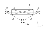
図10に例示するように制御機構6が複数台のドローン3を同時に制御して、複数の方向からコンテナ載置面10の側面を撮影する構成にしてもよい。このとき複数のドローン3をそれぞれ制御機構6で制御する構成にしてもよい。
As illustrated in FIG. 10, the
一方で一台のドローン3を主ドローン3aとして制御機構6で制御を行い、他のドローン3は主ドローンに対して相対的に制御される従ドローン3bとする構成にしてもよい。具体的には例えば従ドローン3bは他のドローン3との相対距離Lを測定する距離センサを備えていて、この相対距離Lが一定となる状態に飛行を制御される。この制御を以下、協同制御ということがある。
On the other hand, one
協同制御では一方の従ドローン3bが、まず主ドローン3aとの相対距離L1が一定となる状態を維持する。これとともに他方の従ドローン3bとの相対距離L3が一定となるように飛行を制御される。同様に他方のドローン3bは、まず主ドローン3aとの相対距離L2を一定に維持して、これにともない一方の従ドローン3bとの相対距離L3が一定となるように飛行を制御される。制御により維持されるべき相対距離L1~L3の値は予め固定値として設定しておくことができる。複数のドローン3は協同制御により互いの相対位置が固定される状態となり、この状態を維持したまま撮影制御によりコンテナ載置面10の撮影を行う。
In cooperative control, one of the slave drones 3b first maintains a state in which the relative distance L1 with respect to the
距離センサは、例えば上下方向zに沿ってレーザ光を走査させる二次元レーザセンサや、三次元レーザセンサで構成することができる。これにより従ドローン3bは、主ドローン3aや他の従ドローン3bとの上下方向zにおける相対的な位置を知ることができる。これにより複数のドローン3は上下方向zにおいて同じ高さとなる位置を飛行しつつ、相対距離Lが一定となるように制御される。
The distance sensor can be composed of, for example, a two-dimensional laser sensor or a three-dimensional laser sensor that scans laser light along the vertical direction z. This allows the
図10に例示する実施形態では一台の主ドローン3aが長手方向撮影制御により撮影を行う。二台の従ドローン3bが短手方向撮影制御により撮影を行う。クレーンオペレータはコンテナ載置面10および荷役対象のコンテナ9の側面を多方向から確認できるので、クレーンオペレータが荷役対象のコンテナ9やコンテナ載置面10等の状況をより正確に確認できるようになる。
In the embodiment illustrated in FIG. 10, one
図10に例示する実施形態では、ドローン3が船倉の中で使用される場合は通路18の中を二台の従ドローン3bが移動する。ドローン3が甲鈑17よりも高い位置で使用される場合は、ドローン3が風等の影響を受ける可能性がある。協同制御により複数のドローン3の相対位置を固定しやすくなるので、風等がドローン3の飛行に与える影響を抑制するには有利である。協同制御を行う際に使用するドローン3は三台に限らず、二台でもよく、四台以上としてもよい。
In the embodiment illustrated in FIG. 10, two
1 クレーン運転補助システム
2 カメラ
3 ドローン
3a 主ドローン
3b 従ドローン
4 モニタ
5 運転室
6 制御機構
7 通信機構
8 スプレッダ
9 コンテナ
10 コンテナ載置面
11 位置情報取得機構
12 取得部
13 管理システム
14 コンテナ船
15 隔壁
16 セルガイド
17 甲鈑
18 通路
19 側壁
P1 (コンテナ載置面の)位置情報
P2 (ドローンの)位置情報
D1 画像データ
x 短手方向
y 長手方向
z 上下方向
L1、L2、L3 相対距離
1 Crane
Claims (7)
周囲との距離を測定する複数の距離センサと前記カメラとが設置されるドローンとこのドローンを制御する制御機構とを備えていて、
荷役対象の前記コンテナが載置されるコンテナ載置面の近傍に前記ドローンを待機させて、荷役対象の前記コンテナの側面を前記ドローンの前記カメラで撮影させる撮影制御と、
前記距離センサに周囲の障害物までの距離を測定させてこの距離が所定の値よりも小さくならない状態に前記ドローンの位置を制御する衝突防止制御とを行なう構成を前記制御機構が有していて、
前記制御機構が撮影制御と衝突防止制御とを同時並行で行う構成を有することを特徴とするクレーン運転補助システム。 A crane operation assistance system comprising: a camera for photographing a container being loaded and unloaded by a spreader of a container crane;
A drone in which a plurality of distance sensors for measuring the distance to the surroundings and the camera are installed, and a control mechanism for controlling the drone,
shooting control for causing the drone to stand by in the vicinity of a container placement surface on which the container to be handled is placed, and to shoot a side surface of the container to be handled by the camera of the drone;
The control mechanism has a configuration for performing anti-collision control for controlling the position of the drone so that the distance sensor measures the distance to surrounding obstacles and the distance does not become smaller than a predetermined value. ,
A crane operation assistance system, wherein the control mechanism is configured to simultaneously perform photographing control and collision prevention control.
前記カメラが設置されるドローンとこのドローンを制御する制御機構とを備えていて、
荷役対象の前記コンテナが載置されるコンテナ載置面の近傍に前記ドローンを待機させて、荷役対象の前記コンテナの側面を前記ドローンの前記カメラで撮影させる撮影制御と、
前記ドローンが自身の位置情報を取得する位置情報取得機構を有していて、前記コンテナ載置面の位置情報と前記ドローンの位置情報とを取得する取得部を前記制御機構が有していて、前記取得部で得られる情報に基づいて前記コンテナ載置面の近傍に前記ドローンを移動させる移動制御と、
コンテナヤードに設置されていて前記コンテナ載置面の位置情報を格納する管理システムから取得される前記コンテナ載置面の位置情報、および前記管理システムに予め記憶されているコンテナ船の側壁の位置の情報に基づき、前記コンテナ載置面の長手方向の側面を撮影できる位置に前記ドローンが移動可能か否かを判断して、前記ドローンが移動可能である場合は前記コンテナの長辺方向の側面を撮影する長手方向撮影制御を選択して、前記ドローンが移動不可能である場合は前記コンテナの短辺方向の側面を撮影する短辺方向撮影制御を選択する選択制御とを行う構成を前記制御機構が有することを特徴とするクレーン運転補助システム。 A crane operation assistance system comprising: a camera for photographing a container being loaded and unloaded by a spreader of a container crane;
A drone on which the camera is installed and a control mechanism for controlling the drone,
shooting control for causing the drone to stand by in the vicinity of a container placement surface on which the container to be handled is placed, and to shoot a side surface of the container to be handled by the camera of the drone;
The drone has a position information acquisition mechanism that acquires its own position information, and the control mechanism has an acquisition unit that acquires the position information of the container mounting surface and the position information of the drone, movement control for moving the drone to the vicinity of the container placement surface based on the information obtained by the acquisition unit;
Positional information of the container mounting surface acquired from a management system installed in the container yard and storing the positional information of the container mounting surface, and the position of the side wall of the container ship pre-stored in the management system. Based on the information, it is determined whether or not the drone can move to a position where the longitudinal side of the container mounting surface can be photographed, and if the drone can move, the longitudinal side of the container can be captured . The control mechanism performs selection control for selecting longitudinal direction photography control for photographing, and selecting short side direction photography control for photographing the short side direction side surface of the container when the drone is immovable. A crane operation assistance system characterized by having
前記制御機構が、前記通路の中で前記ドローンを飛行させる構成を有する請求項1~3のいずれかに記載のクレーン運転補助システム。 A passage is formed in advance inside the bulkhead that separates the hold in the longitudinal direction of the container ship,
The crane operation assistance system according to any one of claims 1 to 3, wherein the control mechanism has a configuration to fly the drone in the passage.
前記制御機構で取得される前記コンテナ載置面の位置情報が前記甲鈑よりも高い位置であった場合、前記モニタの画像を前記ドローンの前記カメラから作業員のカメラに自動で切り替える制御を行う構成を有する請求項1~4のいずれかに記載のクレーン運転補助システム。 The control mechanism has a configuration in which the drone is allowed to fly only in a hold that is lower than the armor of the container ship, and airspace restriction control is performed to restrict the drone from entering a position higher than the armor. and
When the position information of the container placement surface acquired by the control mechanism is a position higher than the armor, control is performed to automatically switch the image on the monitor from the camera of the drone to the camera of the worker. The crane operation assistance system according to any one of claims 1 to 4, having a configuration.
周囲との距離を測定する複数の距離センサと前記カメラとをドローンに設置して、荷役対象の前記コンテナが載置されるコンテナ載置面の近傍に前記ドローンを待機させて、荷役対象の前記コンテナの側面を前記ドローンの前記カメラで撮影させる撮影制御と、
前記距離センサに周囲の障害物までの距離を測定させてこの距離が所定の値よりも小さくならない状態に前記ドローンの位置を制御する衝突防止制御とを行う構成を有するとともに、
撮影制御と衝突防止制御とを同時並行で行う構成を有することを特徴とするクレーン運転補助方法。 A crane operation assisting method for photographing a container being unloaded by a spreader of a container crane with a camera and displaying the photographed image on a monitor in the operator's cab of the container crane,
A plurality of distance sensors for measuring the distance to the surroundings and the camera are installed on the drone, the drone is made to stand by near the container mounting surface on which the container to be handled is mounted, and the container to be handled is placed. Shooting control for shooting the side of the container with the camera of the drone;
a configuration for performing anti-collision control for controlling the position of the drone so that the distance sensor measures the distance to surrounding obstacles and the distance does not become smaller than a predetermined value;
A crane operation assistance method characterized by having a configuration in which photographing control and collision prevention control are performed simultaneously.
前記カメラをドローンに設置して、荷役対象の前記コンテナが載置されるコンテナ載置面の近傍に前記ドローンを待機させて、荷役対象の前記コンテナの側面を前記ドローンの前記カメラで撮影させる撮影制御と、
荷役対象の前記コンテナが載置されるコンテナ載置面の位置情報と前記ドローンの位置情報とに基づいて前記コンテナ載置面の近傍に前記ドローンを移動させる移動制御と、
コンテナヤードに設置されていて前記コンテナ載置面の位置情報を格納する管理システムから取得される前記コンテナ載置面の位置情報、および前記管理システムに予め記憶されているコンテナ船の側壁の位置の情報に基づき、前記コンテナ載置面の長手方向の側面を撮影できる位置に前記ドローンが移動可能か否かを判断して、前記ドローンが移動可能である場合は前記コンテナの長辺方向の側面を撮影する長手方向撮影制御を選択して、前記ドローンが移動不可能である場合は前記コンテナの短辺方向の側面を撮影する短辺方向撮影制御を選択する選択制御とを行うことを特徴とするクレーン運転補助方法。 A crane operation assisting method for photographing a container being unloaded by a spreader of a container crane with a camera and displaying the photographed image on a monitor in the operator's cab of the container crane,
The camera is installed in a drone, the drone is made to stand by in the vicinity of the container placement surface on which the container to be handled is placed, and the side of the container to be handled is photographed by the camera of the drone. control and
movement control for moving the drone to the vicinity of the container mounting surface based on the position information of the container mounting surface on which the container to be handled is mounted and the position information of the drone;
Positional information of the container mounting surface acquired from a management system installed in the container yard and storing the positional information of the container mounting surface, and the position of the side wall of the container ship pre-stored in the management system. Based on the information, it is determined whether or not the drone can move to a position where the longitudinal side of the container mounting surface can be photographed, and if the drone can move, the longitudinal side of the container can be captured . selection control for selecting a longitudinal direction photographing control for photographing, and selecting short side direction photographing control for photographing a side surface of the container in a short side direction when the drone cannot move . Crane operation assistance method.
Priority Applications (1)
| Application Number | Priority Date | Filing Date | Title |
|---|---|---|---|
| JP2021112114A JP7128329B2 (en) | 2018-03-13 | 2021-07-06 | CRANE OPERATION ASSISTANCE SYSTEM AND CRANE OPERATION ASSISTANCE METHOD |
Applications Claiming Priority (2)
| Application Number | Priority Date | Filing Date | Title |
|---|---|---|---|
| JP2018045805A JP6910316B2 (en) | 2018-03-13 | 2018-03-13 | Crane operation assistance system and crane operation assistance method |
| JP2021112114A JP7128329B2 (en) | 2018-03-13 | 2021-07-06 | CRANE OPERATION ASSISTANCE SYSTEM AND CRANE OPERATION ASSISTANCE METHOD |
Related Parent Applications (1)
| Application Number | Title | Priority Date | Filing Date |
|---|---|---|---|
| JP2018045805A Division JP6910316B2 (en) | 2018-03-13 | 2018-03-13 | Crane operation assistance system and crane operation assistance method |
Publications (2)
| Publication Number | Publication Date |
|---|---|
| JP2021169372A JP2021169372A (en) | 2021-10-28 |
| JP7128329B2 true JP7128329B2 (en) | 2022-08-30 |
Family
ID=67992263
Family Applications (2)
| Application Number | Title | Priority Date | Filing Date |
|---|---|---|---|
| JP2018045805A Active JP6910316B2 (en) | 2018-03-13 | 2018-03-13 | Crane operation assistance system and crane operation assistance method |
| JP2021112114A Active JP7128329B2 (en) | 2018-03-13 | 2021-07-06 | CRANE OPERATION ASSISTANCE SYSTEM AND CRANE OPERATION ASSISTANCE METHOD |
Family Applications Before (1)
| Application Number | Title | Priority Date | Filing Date |
|---|---|---|---|
| JP2018045805A Active JP6910316B2 (en) | 2018-03-13 | 2018-03-13 | Crane operation assistance system and crane operation assistance method |
Country Status (1)
| Country | Link |
|---|---|
| JP (2) | JP6910316B2 (en) |
Families Citing this family (6)
| Publication number | Priority date | Publication date | Assignee | Title |
|---|---|---|---|---|
| JP7548749B2 (en) * | 2020-07-30 | 2024-09-10 | 住友重機械搬送システム株式会社 | Automatic crane system and method for controlling the automatic crane system |
| JP7521359B2 (en) * | 2020-09-29 | 2024-07-24 | コベルコ建機株式会社 | Remote operation support device and remote operation support system |
| AU2021273629A1 (en) * | 2020-12-16 | 2022-06-30 | Aurora Flight Sciences Corporation, a subsidiary of The Boeing Company | Aircraft sensor system synchronization |
| CN114217606B (en) * | 2021-11-15 | 2024-05-28 | 武汉港迪智能技术有限公司 | Remote intelligent control system and method for gantry crane |
| WO2023170940A1 (en) * | 2022-03-11 | 2023-09-14 | 日本電気株式会社 | Control device, flying object, measurement system, control method, flying object control method, and storage medium |
| JP7740801B2 (en) * | 2022-04-08 | 2025-09-17 | 住友建機株式会社 | Road machinery |
Citations (6)
| Publication number | Priority date | Publication date | Assignee | Title |
|---|---|---|---|---|
| JP2016204058A (en) | 2015-04-15 | 2016-12-08 | 三井造船株式会社 | Crane operation assisting system and crane operation assisting method |
| JP2017078575A (en) | 2015-10-19 | 2017-04-27 | エナジー・ソリューションズ株式会社 | Inspection system and inspection method |
| JP2017087916A (en) | 2015-11-09 | 2017-05-25 | 株式会社プロドローン | Unmanned moving object control method and unmanned moving object monitoring device |
| US20170345320A1 (en) | 2016-05-31 | 2017-11-30 | Dronomy Ltd. | Monitoring a Construction Site Using an Unmanned Aerial Vehicle |
| JP2017226259A (en) | 2016-06-21 | 2017-12-28 | 株式会社日立製作所 | Pipe facility inspection vehicle and pipeline facility inspection system using the same |
| JP2019048681A (en) | 2017-09-08 | 2019-03-28 | 住友重機械搬送システム株式会社 | Cargo handling and conveying system, cargo handling and conveying device, and cargo handling and conveying method |
Family Cites Families (2)
| Publication number | Priority date | Publication date | Assignee | Title |
|---|---|---|---|---|
| JP2005138952A (en) * | 2003-11-06 | 2005-06-02 | Mitsubishi Heavy Ind Ltd | Method for operating yard crane, and operating system for the same |
| JP2018188250A (en) * | 2017-04-28 | 2018-11-29 | Jfeエンジニアリング株式会社 | Operation support method and apparatus for cargo handling machine and maintenance work support method and apparatus |
-
2018
- 2018-03-13 JP JP2018045805A patent/JP6910316B2/en active Active
-
2021
- 2021-07-06 JP JP2021112114A patent/JP7128329B2/en active Active
Patent Citations (6)
| Publication number | Priority date | Publication date | Assignee | Title |
|---|---|---|---|---|
| JP2016204058A (en) | 2015-04-15 | 2016-12-08 | 三井造船株式会社 | Crane operation assisting system and crane operation assisting method |
| JP2017078575A (en) | 2015-10-19 | 2017-04-27 | エナジー・ソリューションズ株式会社 | Inspection system and inspection method |
| JP2017087916A (en) | 2015-11-09 | 2017-05-25 | 株式会社プロドローン | Unmanned moving object control method and unmanned moving object monitoring device |
| US20170345320A1 (en) | 2016-05-31 | 2017-11-30 | Dronomy Ltd. | Monitoring a Construction Site Using an Unmanned Aerial Vehicle |
| JP2017226259A (en) | 2016-06-21 | 2017-12-28 | 株式会社日立製作所 | Pipe facility inspection vehicle and pipeline facility inspection system using the same |
| JP2019048681A (en) | 2017-09-08 | 2019-03-28 | 住友重機械搬送システム株式会社 | Cargo handling and conveying system, cargo handling and conveying device, and cargo handling and conveying method |
Also Published As
| Publication number | Publication date |
|---|---|
| JP2021169372A (en) | 2021-10-28 |
| JP6910316B2 (en) | 2021-07-28 |
| JP2019156575A (en) | 2019-09-19 |
Similar Documents
| Publication | Publication Date | Title |
|---|---|---|
| JP7128329B2 (en) | CRANE OPERATION ASSISTANCE SYSTEM AND CRANE OPERATION ASSISTANCE METHOD | |
| US12406221B2 (en) | Enhanced systems, apparatus, and methods for positioning of an airborne relocatable communication hub supporting a plurality of wireless devices | |
| EP3033293B1 (en) | Method and system for automatically landing containers on a landing target using a container crane | |
| JP7159822B2 (en) | Delivery system and processing server | |
| JP7308888B2 (en) | Container yard and container yard control method | |
| JP6481178B2 (en) | Crane remote operation method and crane remote operation device | |
| KR20200013352A (en) | The active guided docking station and a combined vehicle for automatically landing the drones at the docking station | |
| JP6925731B2 (en) | Cargo handling system, cargo handling device, and cargo handling method | |
| EP3663236A1 (en) | Cargo monitoring system | |
| JP6309481B2 (en) | Crane driving support method and crane driving support device | |
| JP7622462B2 (en) | Recovery device for unmanned underwater vehicles | |
| JP6971893B2 (en) | Container terminal and its operation method | |
| KR102931591B1 (en) | Automatic Landing System for Flight Vehicle | |
| KR102463548B1 (en) | System for recognizing objects using wired drone | |
| JP2025103189A (en) | Surveillance system | |
| CN120122639A (en) | Task scheduling method, task execution method, system and self-equipping device |
Legal Events
| Date | Code | Title | Description |
|---|---|---|---|
| A621 | Written request for application examination |
Free format text: JAPANESE INTERMEDIATE CODE: A621 Effective date: 20210706 |
|
| A521 | Request for written amendment filed |
Free format text: JAPANESE INTERMEDIATE CODE: A523 Effective date: 20210727 |
|
| A977 | Report on retrieval |
Free format text: JAPANESE INTERMEDIATE CODE: A971007 Effective date: 20220415 |
|
| A131 | Notification of reasons for refusal |
Free format text: JAPANESE INTERMEDIATE CODE: A131 Effective date: 20220510 |
|
| A521 | Request for written amendment filed |
Free format text: JAPANESE INTERMEDIATE CODE: A523 Effective date: 20220711 |
|
| TRDD | Decision of grant or rejection written | ||
| A01 | Written decision to grant a patent or to grant a registration (utility model) |
Free format text: JAPANESE INTERMEDIATE CODE: A01 Effective date: 20220802 |
|
| A61 | First payment of annual fees (during grant procedure) |
Free format text: JAPANESE INTERMEDIATE CODE: A61 Effective date: 20220818 |
|
| R150 | Certificate of patent or registration of utility model |
Ref document number: 7128329 Country of ref document: JP Free format text: JAPANESE INTERMEDIATE CODE: R150 |
|
| S111 | Request for change of ownership or part of ownership |
Free format text: JAPANESE INTERMEDIATE CODE: R313111 |
|
| R350 | Written notification of registration of transfer |
Free format text: JAPANESE INTERMEDIATE CODE: R350 |
|
| R250 | Receipt of annual fees |
Free format text: JAPANESE INTERMEDIATE CODE: R250 |
|
| R250 | Receipt of annual fees |
Free format text: JAPANESE INTERMEDIATE CODE: R250 |