JP7094792B2 - Vibration wave motor and drive - Google Patents
Vibration wave motor and drive Download PDFInfo
- Publication number
- JP7094792B2 JP7094792B2 JP2018117034A JP2018117034A JP7094792B2 JP 7094792 B2 JP7094792 B2 JP 7094792B2 JP 2018117034 A JP2018117034 A JP 2018117034A JP 2018117034 A JP2018117034 A JP 2018117034A JP 7094792 B2 JP7094792 B2 JP 7094792B2
- Authority
- JP
- Japan
- Prior art keywords
- flexible
- fixing
- vibration wave
- wave motor
- fixed
- Prior art date
- Legal status (The legal status is an assumption and is not a legal conclusion. Google has not performed a legal analysis and makes no representation as to the accuracy of the status listed.)
- Active
Links
Images


Classifications
-
- H—ELECTRICITY
- H02—GENERATION; CONVERSION OR DISTRIBUTION OF ELECTRIC POWER
- H02N—ELECTRIC MACHINES NOT OTHERWISE PROVIDED FOR
- H02N2/00—Electric machines in general using piezoelectric effect, electrostriction or magnetostriction
- H02N2/0005—Electric machines in general using piezoelectric effect, electrostriction or magnetostriction producing non-specific motion; Details common to machines covered by H02N2/02 - H02N2/16
- H02N2/001—Driving devices, e.g. vibrators
- H02N2/0015—Driving devices, e.g. vibrators using only bending modes
-
- H—ELECTRICITY
- H02—GENERATION; CONVERSION OR DISTRIBUTION OF ELECTRIC POWER
- H02N—ELECTRIC MACHINES NOT OTHERWISE PROVIDED FOR
- H02N2/00—Electric machines in general using piezoelectric effect, electrostriction or magnetostriction
- H02N2/0005—Electric machines in general using piezoelectric effect, electrostriction or magnetostriction producing non-specific motion; Details common to machines covered by H02N2/02 - H02N2/16
- H02N2/005—Mechanical details, e.g. housings
- H02N2/0055—Supports for driving or driven bodies; Means for pressing driving body against driven body
-
- H—ELECTRICITY
- H02—GENERATION; CONVERSION OR DISTRIBUTION OF ELECTRIC POWER
- H02N—ELECTRIC MACHINES NOT OTHERWISE PROVIDED FOR
- H02N2/00—Electric machines in general using piezoelectric effect, electrostriction or magnetostriction
- H02N2/0005—Electric machines in general using piezoelectric effect, electrostriction or magnetostriction producing non-specific motion; Details common to machines covered by H02N2/02 - H02N2/16
- H02N2/0075—Electrical details, e.g. drive or control circuits or methods
- H02N2/0085—Leads; Wiring arrangements
-
- H—ELECTRICITY
- H02—GENERATION; CONVERSION OR DISTRIBUTION OF ELECTRIC POWER
- H02N—ELECTRIC MACHINES NOT OTHERWISE PROVIDED FOR
- H02N2/00—Electric machines in general using piezoelectric effect, electrostriction or magnetostriction
- H02N2/02—Electric machines in general using piezoelectric effect, electrostriction or magnetostriction producing linear motion, e.g. actuators; Linear positioners ; Linear motors
- H02N2/026—Electric machines in general using piezoelectric effect, electrostriction or magnetostriction producing linear motion, e.g. actuators; Linear positioners ; Linear motors by pressing one or more vibrators against the driven body
-
- G—PHYSICS
- G02—OPTICS
- G02B—OPTICAL ELEMENTS, SYSTEMS OR APPARATUS
- G02B7/00—Mountings, adjusting means, or light-tight connections, for optical elements
- G02B7/02—Mountings, adjusting means, or light-tight connections, for optical elements for lenses
- G02B7/04—Mountings, adjusting means, or light-tight connections, for optical elements for lenses with mechanism for focusing or varying magnification
- G02B7/08—Mountings, adjusting means, or light-tight connections, for optical elements for lenses with mechanism for focusing or varying magnification adapted to co-operate with a remote control mechanism
Landscapes
- General Electrical Machinery Utilizing Piezoelectricity, Electrostriction Or Magnetostriction (AREA)
- Lens Barrels (AREA)
Description
本発明は振動波モータ及び駆動装置に関する。 The present invention relates to a vibration wave motor and a drive device.
特許文献1には、振動板と圧電素子からなる可動部が移動する形態の超音波モータが開示されており、圧電素子に接続されるフレキシブル基板が折り返す構成となっている。
特許文献1の超音波モータでは、フレキシブル基板の折り返し部をベース部材に貼り付ける面がベース部材の可動部側の面にあるため、可動部とベース部材に挟まれた狭い空間で折り返し部をベース部材に固定する必要があり、作業性が悪かった。
In the ultrasonic motor of
本発明の目的は、振動波モータの製造時の作業性を改善した振動波モータを提供することである。 An object of the present invention is to provide a vibration wave motor having improved workability at the time of manufacturing the vibration wave motor.
本発明の振動波モータは、圧電素子と振動板とからなる振動子と、加圧力によって前記振動子が第1の方向に加圧接触する摺動面を有する摩擦部材と、前記摺動面が設けられた側の前記摩擦部材の反対側に配置され、前記振動子と前記摩擦部材の相対的な移動をガイドするガイド部材と、電圧を前記振動子に印加するフレキシブル基板と、前記摩擦部材、前記ガイド部材及び前記フレキシブル基板を固定する固定部材と、を備え、前記振動子と前記摩擦部材とは、第2の方向に相対的に移動し、前記固定部材は、前記フレキシブル基板を固定するフレキ固定部を備え、前記フレキシブル基板は、前記圧電素子に接合される接合部と、前記第2の方向に沿って伸延する第1の伸延部と、該第1の伸延部を反転して折り返す屈曲部と、前記フレキ固定部に固定される被固定部と、を備え、前記フレキシブル基板は、前記摩擦部材に前記振動子が加圧接触する方向と反対の方向に設けられた前記フレキ固定部の面に固定されることを特徴とする。
The vibration wave motor of the present invention has a vibrator composed of a piezoelectric element and a vibrating plate, a friction member having a sliding surface on which the vibrator is pressurized and contacted in the first direction by pressure, and the sliding surface. A guide member arranged on the opposite side of the friction member on the provided side and guiding the relative movement of the vibrator and the friction member, a flexible substrate that applies a voltage to the vibrator, and the friction member. The guide member and the fixing member for fixing the flexible substrate are provided, and the vibrator and the friction member move relatively in a second direction, and the fixing member fixes the flexible substrate. The flexible substrate is provided with a flexible fixing portion, and the flexible substrate has a joint portion bonded to the piezoelectric element, a first stretched portion extending along the second direction, and the first stretched portion inverted. The flexible substrate is provided with a bent portion to be folded back and a fixed portion to be fixed to the flexible fixing portion, and the flexible substrate is provided in a direction opposite to the direction in which the vibrator is pressurized and contacted with the friction member. It is characterized in that it is fixed to the surface of the portion.
振動波モータの製造時の作業性を改善した振動波モータを提供することができる。 It is possible to provide a vibration wave motor having improved workability during manufacturing of the vibration wave motor.
(実施例1)
以下に、本発明の好ましい実施の形態を図1から図5を用いて説明する。図面において、後述する振動子104と摩擦部材101の相対移動の方向をX方向(第2の方向)、後述するバネ110によって振動子104を摩擦部材101に加圧接触する加圧方向をZ方向(第1の方向)とする。また、X方向とZ方向に直交する方向をY方向(第3の方向)と定義する。
(Example 1)
Hereinafter, preferred embodiments of the present invention will be described with reference to FIGS. 1 to 5. In the drawing, the direction of relative movement between the
図1は、本発明の振動波モータ100(超音波モータ)が搭載された撮像装置の構成を示している。尚、本説明において、振動波モータ100が撮像装置に搭載された場合について説明するが、本発明を限定するものではなく、本発明は振動波モータ100により駆動される被駆動部材を有する駆動装置に適用可能である。また、後述の撮像レンズ1とカメラボディ2が一体となっている撮像装置について説明をするが、撮像レンズ1は交換可能なレンズであっても構わない。
FIG. 1 shows the configuration of an image pickup device equipped with the vibration wave motor 100 (ultrasonic motor) of the present invention. In this description, the case where the
図1において、撮像レンズ1とカメラボディ2によって撮像装置の本体が形成されている。撮像レンズ1の内部において、フォーカスレンズ3は振動波モータ100と連結されており、振動波モータ100を構成する振動子104が移動することにより、フォーカスレンズ3は光軸5と略平行な方向に移動可能となる。撮像時にはフォーカスレンズ3が光軸5と略平行な方向に移動し、被写体像は撮像素子4の位置で結像し、合焦した像を生成することが可能となる。
In FIG. 1, the main body of the image pickup apparatus is formed by the
図2(A)、(B)は、本発明の振動波モータ100の構成を示しており、図2(A)は部材ごとに展開した展開図、図2(B)はXZ平面で切断した中央断面図である。本実施例における振動波モータ100は、以下に述べる各部材により形成されている。
2 (A) and 2 (B) show the configuration of the
振動子104は、弾性を有する振動体である振動板102と圧電素子103により構成されている。振動板102と圧電素子103は公知の接着剤等により固着されている。フレキシブル基板116が備える接合部116aは、圧電素子103に圧着されており、フレキシブル基板116を介して圧電素子103に高周波電圧を印加することにより、振動子104に高周波領域の周波数の振動(超音波振動)を励振する。
The
振動子104は、第1の保持部材105に公知の接着剤等により固定されているが、これらの固定は固定されればその方法は限定されない。第2の保持部材107は、後述するローラ108a、108bと板バネ109を介して第1の保持部材105と連結されている。ガイド部材113は、振動子104とX方向に相対的に移動する摩擦部材101の相対的な移動をガイドする部材である。ガイド部材113は摩擦部材101と当接すると共にビス117によって固定部材112の固定部112aに固定される。固定部材112はネジ等によって後述する第2の固定部材119に固定される。
The
複数のバネ110は、4か所において付勢部材111と可動ガイド部材115を連結し、これら複数のバネ110の加圧力によって振動子104を摩擦部材101に加圧接触させている。緩衝部材106aは基材プレート106に貼付されており、基材プレート106は、圧電素子103と付勢部材111の間に配置されている。緩衝部材106a及び基材プレート106は、付勢部材111と圧電素子103との直接接触を防ぎ、圧電素子103の損傷を防止している。
The plurality of
振動板102は接触部102aを備え、接触部102aは摩擦部材101の摺動面101aに前述のバネ110の加圧力により加圧付勢された状態で接触している。振動板102と圧電素子103が接着された状態において、圧電素子103に高周波電圧を印加することで、振動子104に共振現象が起こる。このとき振動子104には2種類の定在波が発生し、振動板102の接触部102aに略楕円運動が発生する。
The
第2の保持部材107と可動ガイド部材115とは不図示のネジ等によって固定されるが、固定されればその方法は限定されない。可動ガイド部材115は3つのV溝の移動案内部を備えており、それぞれの溝に転動ボール114が嵌入されている。一方、ガイド部材113も3つの溝の固定側案内部を備えている。可動ガイド部材115が有する移動側案内部と、ガイド部材113が有する固定側案内部との間で、転動ボール114が挟持されたまま転動する。尚、本実施例においてはガイド部材113が備える3つの溝の内、2つはV溝、1つは有底の平面溝となっているが、転動ボール114が転動できる溝で有れば他の構成であっても構わない。更に、第2の保持部材107は、図5(A)に示すように被駆動体と連結される動力取り出し部である球面突起部107aを有する。球面突起部107aは、被駆動体に連結される連結部材120に当接し、連結部材120は球面突起部107aに+Z方向の付勢力を付与する。この構成により、第2の保持部材107とフォーカスレンズ3がX方向に一体的に動くことが可能となる。そして、連結部材120は図1で説明したフォーカスレンズ3に接続されている。尚、振動子104、第2の保持部材107、基材プレート106、第1の保持部材105、ローラ108a、108b、板バネ109、バネ110、付勢部材111、可動ガイド部材115が一体化されて可動部118を構成する。
The
次に、バネ110が発生する加圧力について説明する。本発明において、複数のバネ110は振動子104を囲う様に4か所に配置されており、付勢部材111及び可動ガイド部材115は、それぞれが備えるバネ掛け部を介して連結されている。バネ110の加圧力は、緩衝部材106aが貼付された基材プレート106を介して、振動子104を摩擦部材101にZ方向に加圧する付勢力となる。そして、振動板102の接触部102aは摩擦部材101に対し加圧された状態で接触する。また、バネ110の加圧力で、ガイド部材113と可動ガイド部材115の間に挟持された状態の転動ボール114はその状態のまま転動する。この構成により、バネ110の加圧力による摩擦摺動負荷を低減している。
Next, the pressing force generated by the
この加圧接触状態において、圧電素子103に駆動電圧である高周波電圧が印加されると、振動子104に発生した略楕円運動が効率的に摩擦部材101へ伝達する。その結果、固定側である摩擦部材101及び固定部材112に対して、可動部118がX方向又はX方向に相対的に移動する。
When a high-frequency voltage, which is a driving voltage, is applied to the
図2(B)を用いて、第1の保持部材105と第2の保持部材107の連結手段について説明する。図2(B)において、ローラ108a、108bが第1の保持部材105と第2の保持部材107の間に配置されている。更に、振動子104の相対移動の方向であるX方向に対して所定の付勢力を有する板バネ109が第2の保持部材107とローラ108aの間に配置され、ローラ108a、108bはバネ110による加圧方向(Z方向)に移動自在である。板バネ109の付勢力により、第1の保持部材105は一方のローラ108aを介して-X方向に付勢されると共に、第2の保持部材107は+X方向に付勢される。この構成により、他方のローラ108bは第1の保持部材105と第2の保持部材107との間で挟持される。
A means for connecting the first holding
以上のように構成することにより、可動部118の相対移動の方向にはガタの発生が無く、また、バネ110による加圧方向にはローラ108a、108bの転動により移動自在となるため、振動子104の駆動を阻害すること無く連結することが可能となる。尚、本発明においては、第1の保持部材105と第2の保持部材107との間の連結手段を構成する弾性部材として板バネ109を用いているが、ガタを無くすことができる部材であれば他の部材でも構わない。
With the above configuration, there is no play in the direction of relative movement of the
上記の板バネ109の付勢力は、振動子104の駆動開始時及び駆動停止時に発生する加減速による慣性力よりも大きくなるように設定されている。この構成により、振動子104と第1の保持部材105は、駆動時の慣性力による移動方向の相対変位が発生せず安定した駆動制御を実現することができる。
The urging force of the
次に、本発明の要部の構造及び効果について説明する。図3(A)、(B)は、本発明の振動波モータ100の組立方法を説明する図である。図3(A)は、可動部118とガイド部材113を保持した摩擦部材101を固定部材112に固定する工程を説明する図である。まず、摩擦部材101とガイド部材113を治具等で位置決め保持し、可動部118を組み込む。このときガイド部材113と可動ガイド部材115の間に転動ボール114を挟み込んでおく。すると、摩擦部材101とガイド部材113が、複数のバネ110の加圧力で可動ガイド部材115と付勢部材111に挟持された状態となる。この可動部118とガイド部材113を保持した摩擦部材101を固定部材112の固定部112aにビス117で固定する。
Next, the structure and effect of the main part of the present invention will be described. 3A and 3B are diagrams illustrating an assembly method of the
もし摩擦部材101とガイド部材113を固定部材112に固定した後に可動部118を組み付ける構成であるとすると、可動ガイド部材115及び付勢部材111のバネ110を組み付ける部位が固定部材112に囲われてしまう。その結果、可動ガイド部材115及び付勢部材111に複数のバネ110をかける際の作業性が非常に悪くなってしまう。しかしながら、本発明の振動波モータ100では、図3(A)のように摩擦部材101を固定部材112に固定する前に、可動部118を摩擦部材101に組み付けておく。その結果、可動ガイド部材115及び付勢部材111のバネ110を組み付ける部位が固定部材112に囲われず、開放された状態で複数のバネ110を組み込むことができる。以上、複数のバネ110を可動ガイド部材115及び付勢部材111にかける際の作業性を向上させることができる。
If the
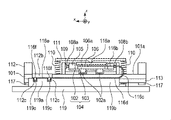
図3(B)は、フレキシブル基板116が有する被固定部116eを固定部材112が有するフレキ固定部112bに固定する工程を説明する図である。本発明の振動波モータ100では、可動部118とガイド部材113を保持した摩擦部材101を固定部材112の固定部112aに固定した後に、フレキシブル基板116の被固定部116eをフレキ固定部112bに固定する。
FIG. 3B is a diagram illustrating a step of fixing the fixed
この際、フレキ固定部112bは振動子104が配置される側の面と反対側である-Z方向の面に設けられており、被固定部116eは両面テープなどでこのフレキ固定部112bに固定される。フレキ固定部112bには、Z方向に突出したフレキ位置決め突起112cが複数あり、フレキ位置決め突起112cはフレキシブル基板116に設けられた穴部116fと係合している。これにより被固定部116eのフレキ固定部112bに対するXY平面方向の位置を決めている。
At this time, the
従来では、狭い空間でフレキシブル基板を固定する必要があり、作業性が悪かった。一方、本発明の振動波モータ100では、フレキシブル基板116を図3(B)の点線のように取り回し、フレキ固定部112bの-Z方向の面に被固定部116eを固定する。そして、フレキ固定部112bの-Z方向の面が外側に露出しているため、フレキ固定部112bに被固定部116eを貼り付ける際の作業性が大幅に改善されている。
In the past, it was necessary to fix the flexible substrate in a narrow space, and workability was poor. On the other hand, in the
次に、フレキシブル基板116の各部位と、フレキ固定部112bの配置について説明する。フレキシブル基板116は、接合部116aで圧電素子103と接合されている。フレキシブル基板116は、この接合部116aから-X方向に沿って伸延する第1の伸延部116bを有する。更に、第1の伸延部116bを-X方向から+X方向に反転して折り返す屈曲部116c、屈曲部116cから+X方向に沿って延伸する第2の伸延部116dを有する。そして、フレキシブル基板116をフレキ固定部112bに固定する被固定部116eを有する。第2の伸延部116dは、屈曲部116cと被固定部116eの間に配置される。尚、フレキ固定部112bは、Z方向において第1の伸延部116b(第2の伸延部116d)と被固定部116eの間に配置されている。
Next, each part of the
フレキシブル基板116は、接合部116aで振動子104に圧着され、被固定部116eで固定部材112に固定されている。フレキシブル基板116は、フレキシブル基板116の伸延方向を反転させる屈曲部116cにより、振動子104がX方向に移動する際には、この屈曲部116cがX方向に移動し、振動子104と固定部材112の相対的な位置のずれを吸収することができる。この構成により、振動子104がX方向に移動しても、フレキシブル基板116には移動による張力がかからない。
The
図4は、固定部材112を保持する第2の固定部材119を説明する図である。第2の固定部材119には、フレキ固定部112bに対向する位置に第2のフレキ固定部119aが形成されている。そして、フレキ固定部112bの-Z方向の面と、第2のフレキ固定部119aの+Z方向の面との間に、フレキシブル基板116の被固定部116eが挟持されている。また、フレキ位置決め突起112cに対応する位置に穴部119cが形成されると共に、フレキシブル基板116の穴部116fはフレキ位置決め突起112cに係合している。この構成は、もし被固定部116eをフレキ固定部112bに固定している両面テープが、屈曲部116cの復元力によって剥離してしまった場合に優れた効果を発揮する。すなわち、被固定部116eは穴部116fでフレキ位置決め突起112cと係合し、かつフレキ固定部112bの-Z方向の面と、第2のフレキ固定部119aの+Z方向の面との間に挟持されているため、被固定部116eがずれてしまうことがない。
FIG. 4 is a diagram illustrating a
第2のフレキ固定部119aはX方向に延伸されており、更に第2の固定部材119には、第2の伸延部116dとZ方向で当接するフレキ当接部119bがX方向に沿って形成されている。屈曲部116cの復元力によって第2の伸延部116dは-Z方向にずれようとするが、第2の伸延部116dをフレキ当接部119bで受けることで、屈曲部116cの形状を保つことができる。このように第2の固定部材119は、第2のフレキ固定部119aとフレキ当接部119bを備えることで、フレキシブル基板116を固定する機能と、屈曲部116cのZ方向の復元力を受ける機能を担っている。
The second flexible fixing
図5(A)、(B)はフレキ固定部112bの位置を説明する図である。図5(A)は+X方向から見た図で、図5(B)は+Y方向から見た図である。まずY方向の位置について説明する。Y方向において、複数のバネ110は摩擦部材101の両側に配置されている。ここで、複数のバネ110のY方向の位置を位置+A及び位置-Aとする。また、フレキシブル基板116を圧電素子103に接合する接合部116aは、Y方向において摩擦部材101の中心に配置されている。ここで、接合部116aのY方向の位置を位置Bとする。
5 (A) and 5 (B) are views for explaining the position of the
フレキシブル基板116の第1の伸延部116b、屈曲部116c、第2の伸延部116d、被固定部116e、そして固定部材112のフレキ固定部112bは、+Y方向側のバネ110の更に+Y方向の外側、つまり複数のバネ110の外側に配置されている。この構成は、第1の伸延部116bが接合部116aから-X方向に沿って伸延すると共にY方向に離間して伸延し、屈曲部116cが第1の伸延部116bを+X方向に反転して折り返すことで形成される。ここで、第1の伸延部116b、屈曲部116c、第2の伸延部116d、被固定部116e、そして固定部材112のフレキ固定部112bの位置を+Cとする。
The first
本発明の振動波モータ100では、Y方向において、複数のバネ110の位置+A及び位置-Aの内側に接合部116aを位置Bに配置し、複数のバネ110の位置+Aの外側にフレキ固定部112bを位置+Cに配置する。フレキシブル基板116の接合部116aは可動側の圧電素子103に、被固定部116eは固定側のフレキ固定部112bに固定されており、屈曲部116cがX方向に移動する。このとき、もし付勢部材111、複数のバネ110、可動ガイド部材115で囲まれた領域内に第1の伸延部116b、屈曲部116c、第2の伸延部116d、被固定部116e、フレキ固定部112bを設けるとする。そうすると、付勢部材111と可動ガイド部材115に挟まれて決まるZ方向のサイズと、複数のバネ110に挟まれて決まるY方向のサイズが大きくなる。その結果、可動部118のYZ平面に投影した面積が大きくなり、振動波モータ100が大型化してしまう。
In the
そこで、図5(A)に示すように、Y方向において、複数のバネ110の内側に接合部116aを配置し、複数のバネ110の外側に被固定部116eとフレキ固定部112bを配置する。この構成により、振動波モータ100の小型化を実現している。
Therefore, as shown in FIG. 5A, the
次に、Z方向の位置について説明する。可動ガイド部材115、ガイド部材113、転動ボール114からなる転動ガイド機構は、摺動面101aの反対側である-Z方向の位置に配置されている。摺動面101aのZ方向の位置を位置-D、被固定部116eのZ方向の位置を位置-E、そして転動ボール114のZ方向の位置を位置-Fとする。Z方向においては、位置-Dと位置-Fの間に位置-Eが位置している。
Next, the position in the Z direction will be described. The rolling guide mechanism including the
従来の超音波モータでは、Z方向において、各部材及び固定部位が積み重なるため、超音波モータがZ方向に大型化していた。しかしながら、本発明の振動波モータ100では、摺動面101aの振動子104と反対側(-Z方向)に、転動ガイド機構とフレキシブル基板116の被固定部116eの両方を配置している。そして転動ガイド機構と、フレキシブル基板116の被固定部116eとフレキ固定部112bは、Y方向にずれて配置されている。この構成により、転動ガイド機構とフレキシブル基板116の被固定部116eとフレキ固定部112bがZ方向に積み重なって、振動波モータ100がZ方向に大型化するのを防ぐことができる。
In the conventional ultrasonic motor, since each member and the fixed portion are stacked in the Z direction, the ultrasonic motor has become larger in the Z direction. However, in the
本発明の振動波モータ100では、転動ガイド機構が摩擦部材101の-Z方向に配置され、フレキシブル基板116の被固定部116eが複数のバネ110の+Y方向外側に配置されることで、各部品のレイアウトが最適化されている。この構成により振動波モータ100の小型化を実現している。
In the
以上、説明したように、本発明の振動波モータ100では、バネ110の加圧方向であるZ方向において、フレキシブル基板116の第1の伸延部116bと被固定部116eの間に固定部材112のフレキ固定部112bを配置する。そしてフレキシブル基板116はフレキ固定部112bの振動子104が配置される側(+Z方向)の面と反対側(-Z方向)の面に固定される。このような構成とすることで、フレキ固定部112bに被固定部116eを貼り付ける際の作業性を改善した振動波モータ100を提供することができる。
As described above, in the
100 振動波モータ
101 摩擦部材
101a 摺動面
102 振動板
103 圧電素子
104 振動子
110 バネ
112 固定部材
112b フレキ固定部
112c フレキ位置決め突起
113 ガイド部材
114 転動ボール
115 可動ガイド部材
116 フレキシブル基板
116a 接合部
116b 第1の伸延部
116c 屈曲部
116d 第2の伸延部
116e 被固定部
116f 穴部
119 第2の固定部材
119a 第2のフレキ固定部
119b フレキ当接部
100 vibration wave motor
101 Friction member
101a sliding surface
102 Diaphragm
103 Piezoelectric element
104 oscillator
110 spring
112 Fixing member
112b Flexible fixing part
112c Flexible positioning protrusion
113 Guide member
114 Rolling ball
115 Movable guide member
116 Flexible board
116a Joint
116b 1st extension
116c Bent part
116d 2nd extension
116e Fixed part
116f hole
119 Second fixing member
119a Second flexible fixing part
119b Flexible contact part
Claims (8)
加圧力によって前記振動子が第1の方向に加圧接触する摺動面を有する摩擦部材と、
前記摺動面が設けられた側の前記摩擦部材の反対側に配置され、前記振動子と前記摩擦部材の相対的な移動をガイドするガイド部材と、
電圧を前記振動子に印加するフレキシブル基板と、
前記摩擦部材、前記ガイド部材及び前記フレキシブル基板を固定する固定部材と、
を備え、
前記振動子と前記摩擦部材とは、第2の方向に相対的に移動し、
前記固定部材は、前記フレキシブル基板を固定するフレキ固定部を備え、
前記フレキシブル基板は、前記圧電素子に接合される接合部と、前記第2の方向に沿って伸延する第1の伸延部と、該第1の伸延部を反転して折り返す屈曲部と、前記フレキ固定部に固定される被固定部と、を備え、
前記フレキシブル基板は、前記摩擦部材に前記振動子が加圧接触する方向と反対の方向に設けられた前記フレキ固定部の面に固定されることを特徴とする、振動波モータ。 An oscillator consisting of a piezoelectric element and a diaphragm,
A friction member having a sliding surface in which the vibrator is pressure- contacted in the first direction by pressure, and a friction member.
A guide member, which is arranged on the opposite side of the friction member on the side where the sliding surface is provided and guides the relative movement of the vibrator and the friction member,
A flexible substrate that applies voltage to the oscillator,
The friction member, the guide member, and the fixing member for fixing the flexible substrate,
Equipped with
The oscillator and the friction member move relatively in the second direction, and the oscillator and the friction member move relatively to each other.
The fixing member includes a flexible fixing portion for fixing the flexible substrate.
The flexible substrate includes a joint portion joined to the piezoelectric element, a first stretched portion that extends along the second direction, a bent portion that inverts and folds the first stretched portion, and the above-mentioned. With a fixed part that is fixed to the flexible fixing part,
The flexible substrate is a vibration wave motor characterized in that the flexible substrate is fixed to the surface of the flexible fixing portion provided in a direction opposite to the direction in which the vibrator comes into pressure contact with the friction member.
前記フレキ固定部は、前記第1の方向に突出したフレキ位置決め突起を備え、前記フレキ位置決め突起は、前記被固定部が有する穴部に係合し、
前記固定部材を保持する第2の固定部材を更に備え、
前記フレキ固定部と対向する該第2の固定部材には第2のフレキ固定部が備えられ、
前記被固定部は、前記フレキ固定部と前記第2のフレキ固定部との間で挟持され、
前記第2のフレキ固定部は、前記第2の方向に延伸されており、前記第1の方向で前記第2の伸延部と当接するフレキ当接部を有することを特徴とする、請求項1乃至3のいずれか1項に記載の振動波モータ。 The flexible substrate includes a second stretched portion that stretches along the second direction between the bent portion and the fixed portion.
The flexible fixing portion includes a flexible positioning protrusion protruding in the first direction, and the flexible positioning protrusion engages with a hole portion of the fixed portion.
A second fixing member for holding the fixing member is further provided.
The second fixing member facing the flexible fixing portion is provided with a second flexible fixing portion.
The fixed portion is sandwiched between the flexible fixing portion and the second flexible fixing portion.
The first aspect of the present invention is characterized in that the second flexible fixing portion is stretched in the second direction and has a flexible contact portion that abuts on the second stretched portion in the first direction. The vibration wave motor according to any one of 3 to 3.
前記第1の方向において、前記摺動面と前記転動ボールとの間に前記フレキ固定部が配置されていることを特徴とする、請求項1乃至5のいずれか1項に記載の振動波モータ。 A movable guide member that can move in the second direction together with the oscillator, and a rolling roll that is arranged on the opposite side of the sliding surface and is sandwiched between the guide member and the movable guide member by the pressing force. With more balls,
The vibration wave according to any one of claims 1 to 5, wherein the flexible fixing portion is arranged between the sliding surface and the rolling ball in the first direction. motor.
前記振動波モータにより駆動される被駆動部材と、を有することを特徴とする駆動装置。 The vibration wave motor according to any one of claims 1 to 7.
A driving device including a driven member driven by the vibration wave motor.
Priority Applications (2)
| Application Number | Priority Date | Filing Date | Title |
|---|---|---|---|
| JP2018117034A JP7094792B2 (en) | 2018-06-20 | 2018-06-20 | Vibration wave motor and drive |
| US16/440,388 US11245343B2 (en) | 2018-06-20 | 2019-06-13 | Vibration wave motor and driving device |
Applications Claiming Priority (1)
| Application Number | Priority Date | Filing Date | Title |
|---|---|---|---|
| JP2018117034A JP7094792B2 (en) | 2018-06-20 | 2018-06-20 | Vibration wave motor and drive |
Publications (3)
| Publication Number | Publication Date |
|---|---|
| JP2019221073A JP2019221073A (en) | 2019-12-26 |
| JP2019221073A5 JP2019221073A5 (en) | 2021-07-26 |
| JP7094792B2 true JP7094792B2 (en) | 2022-07-04 |
Family
ID=68982335
Family Applications (1)
| Application Number | Title | Priority Date | Filing Date |
|---|---|---|---|
| JP2018117034A Active JP7094792B2 (en) | 2018-06-20 | 2018-06-20 | Vibration wave motor and drive |
Country Status (2)
| Country | Link |
|---|---|
| US (1) | US11245343B2 (en) |
| JP (1) | JP7094792B2 (en) |
Families Citing this family (4)
| Publication number | Priority date | Publication date | Assignee | Title |
|---|---|---|---|---|
| JP7207949B2 (en) * | 2018-10-31 | 2023-01-18 | キヤノン株式会社 | Vibration wave motor and drive device with vibration wave motor |
| JP7358085B2 (en) * | 2019-06-20 | 2023-10-10 | キヤノン株式会社 | Vibration wave motor and drive device |
| JP7258674B2 (en) | 2019-06-24 | 2023-04-17 | キヤノン株式会社 | Vibrating motors, lens devices, and electronic devices |
| JP7258675B2 (en) | 2019-06-24 | 2023-04-17 | キヤノン株式会社 | Vibrating motors and optical equipment |
Citations (3)
| Publication number | Priority date | Publication date | Assignee | Title |
|---|---|---|---|---|
| JP2016100928A (en) | 2014-11-19 | 2016-05-30 | キヤノン株式会社 | Drive device |
| JP2017200366A (en) | 2016-04-28 | 2017-11-02 | キヤノン株式会社 | Vibration wave motor and electronic device equipped with vibration wave motor |
| JP2017198925A (en) | 2016-04-28 | 2017-11-02 | キヤノン株式会社 | Oscillatory wave motor and device using the same |
Family Cites Families (12)
| Publication number | Priority date | Publication date | Assignee | Title |
|---|---|---|---|---|
| JPH06121560A (en) * | 1992-10-07 | 1994-04-28 | Olympus Optical Co Ltd | Ultrasonic motor |
| JP5913857B2 (en) | 2011-08-05 | 2016-04-27 | キヤノン株式会社 | Ultrasonic motor and lens apparatus having the same |
| JP5744670B2 (en) | 2011-08-05 | 2015-07-08 | キヤノン株式会社 | Ultrasonic motor and lens apparatus having the same |
| JP5975614B2 (en) | 2011-09-20 | 2016-08-23 | キヤノン株式会社 | Ultrasonic motor and lens apparatus having the same |
| JP6218501B2 (en) | 2013-08-26 | 2017-10-25 | キヤノン株式会社 | Vibration wave motor |
| JP6501487B2 (en) | 2014-10-27 | 2019-04-17 | キヤノン株式会社 | Ultrasonic motor and drive device using ultrasonic motor |
| JP6448310B2 (en) | 2014-10-30 | 2019-01-09 | キヤノン株式会社 | Vibrator and ultrasonic motor |
| JP6570335B2 (en) | 2015-06-17 | 2019-09-04 | キヤノン株式会社 | Vibration type actuator, lens driving device and ultrasonic motor |
| JP6305377B2 (en) * | 2015-08-04 | 2018-04-04 | キヤノン株式会社 | Vibrating actuator, device and optical instrument |
| JP6829555B2 (en) | 2016-06-23 | 2021-02-10 | キヤノン株式会社 | Vibration wave motor and lens drive |
| JP6788493B2 (en) * | 2016-12-22 | 2020-11-25 | キヤノン株式会社 | Vibration wave motor and equipment using it |
| JP6605012B2 (en) | 2017-12-08 | 2019-11-13 | キヤノン株式会社 | Vibration wave motor and lens driving device using vibration wave motor |
-
2018
- 2018-06-20 JP JP2018117034A patent/JP7094792B2/en active Active
-
2019
- 2019-06-13 US US16/440,388 patent/US11245343B2/en active Active
Patent Citations (3)
| Publication number | Priority date | Publication date | Assignee | Title |
|---|---|---|---|---|
| JP2016100928A (en) | 2014-11-19 | 2016-05-30 | キヤノン株式会社 | Drive device |
| JP2017200366A (en) | 2016-04-28 | 2017-11-02 | キヤノン株式会社 | Vibration wave motor and electronic device equipped with vibration wave motor |
| JP2017198925A (en) | 2016-04-28 | 2017-11-02 | キヤノン株式会社 | Oscillatory wave motor and device using the same |
Also Published As
| Publication number | Publication date |
|---|---|
| US11245343B2 (en) | 2022-02-08 |
| US20190393807A1 (en) | 2019-12-26 |
| JP2019221073A (en) | 2019-12-26 |
Similar Documents
| Publication | Publication Date | Title |
|---|---|---|
| JP7094792B2 (en) | Vibration wave motor and drive | |
| CN110112953B (en) | Motor and electronic apparatus including the same | |
| CN110199216B (en) | Drives, optics and cameras | |
| US11038439B2 (en) | Vibration-wave motor | |
| JP5683643B2 (en) | Linear ultrasonic motor and optical apparatus having the same | |
| US10804820B2 (en) | Motor and apparatus using the same | |
| US20170315324A1 (en) | Motor and apparatus using the same | |
| JP2017200366A (en) | Vibration wave motor and electronic device equipped with vibration wave motor | |
| JP6122452B2 (en) | Actuator | |
| WO2016002917A1 (en) | Vibration-type actuator, lens barrel, image-capturing device, and automatic stage | |
| JP6882036B2 (en) | Imaging device with vibration wave motor and vibration wave motor | |
| US10558011B2 (en) | Vibration actuator and electronic apparatus using vibration actuator | |
| JP2019039997A (en) | Vibration wave motor and drive device | |
| JP7112250B2 (en) | Oscillating wave motor and drive | |
| JP7016898B2 (en) | Vibration type motors, lens devices, and electronic devices | |
| JP7207949B2 (en) | Vibration wave motor and drive device with vibration wave motor | |
| CN107947626B (en) | Motor using vibrator and electronic device | |
| JP2018101045A (en) | Lens drive device, lens barrel, and imaging device | |
| CN107342705B (en) | Motor and electronic apparatus including the same | |
| JP7581066B2 (en) | Vibration Wave Drive Device | |
| JP7826073B2 (en) | Motor, drive device, lens device, and imaging device | |
| JP2020137237A (en) | Lens barrel drive device with vibration wave motor and vibration wave motor | |
| JP7169851B2 (en) | Vibration wave motor and lens device using vibration wave motor | |
| JP6537482B2 (en) | Vibration wave motor and electronic equipment | |
| JP2019221072A (en) | Vibration wave motor and drive unit with vibration wave motor |
Legal Events
| Date | Code | Title | Description |
|---|---|---|---|
| A521 | Request for written amendment filed |
Free format text: JAPANESE INTERMEDIATE CODE: A523 Effective date: 20210610 |
|
| A621 | Written request for application examination |
Free format text: JAPANESE INTERMEDIATE CODE: A621 Effective date: 20210610 |
|
| TRDD | Decision of grant or rejection written | ||
| A977 | Report on retrieval |
Free format text: JAPANESE INTERMEDIATE CODE: A971007 Effective date: 20220518 |
|
| A01 | Written decision to grant a patent or to grant a registration (utility model) |
Free format text: JAPANESE INTERMEDIATE CODE: A01 Effective date: 20220524 |
|
| A61 | First payment of annual fees (during grant procedure) |
Free format text: JAPANESE INTERMEDIATE CODE: A61 Effective date: 20220622 |
|
| R151 | Written notification of patent or utility model registration |
Ref document number: 7094792 Country of ref document: JP Free format text: JAPANESE INTERMEDIATE CODE: R151 |