JP6570335B2 - Vibration type actuator, lens driving device and ultrasonic motor - Google Patents
Vibration type actuator, lens driving device and ultrasonic motor Download PDFInfo
- Publication number
- JP6570335B2 JP6570335B2 JP2015122190A JP2015122190A JP6570335B2 JP 6570335 B2 JP6570335 B2 JP 6570335B2 JP 2015122190 A JP2015122190 A JP 2015122190A JP 2015122190 A JP2015122190 A JP 2015122190A JP 6570335 B2 JP6570335 B2 JP 6570335B2
- Authority
- JP
- Japan
- Prior art keywords
- vibration type
- force
- type actuator
- vibrator
- vibration
- Prior art date
- Legal status (The legal status is an assumption and is not a legal conclusion. Google has not performed a legal analysis and makes no representation as to the accuracy of the status listed.)
- Active
Links
- 230000003287 optical effect Effects 0.000 description 10
- 238000010586 diagram Methods 0.000 description 9
- 239000002184 metal Substances 0.000 description 6
- 230000000694 effects Effects 0.000 description 4
- 238000012423 maintenance Methods 0.000 description 4
- 239000000463 material Substances 0.000 description 3
- HFGPZNIAWCZYJU-UHFFFAOYSA-N lead zirconate titanate Chemical compound [O-2].[O-2].[O-2].[O-2].[O-2].[Ti+4].[Zr+4].[Pb+2] HFGPZNIAWCZYJU-UHFFFAOYSA-N 0.000 description 2
- 229910052451 lead zirconate titanate Inorganic materials 0.000 description 2
- 238000005096 rolling process Methods 0.000 description 2
- 238000005452 bending Methods 0.000 description 1
- 230000006835 compression Effects 0.000 description 1
- 238000007906 compression Methods 0.000 description 1
- 238000000605 extraction Methods 0.000 description 1
- 230000000149 penetrating effect Effects 0.000 description 1
Images


Classifications
-
- H—ELECTRICITY
- H02—GENERATION; CONVERSION OR DISTRIBUTION OF ELECTRIC POWER
- H02N—ELECTRIC MACHINES NOT OTHERWISE PROVIDED FOR
- H02N2/00—Electric machines in general using piezoelectric effect, electrostriction or magnetostriction
- H02N2/02—Electric machines in general using piezoelectric effect, electrostriction or magnetostriction producing linear motion, e.g. actuators; Linear positioners ; Linear motors
- H02N2/04—Constructional details
-
- H—ELECTRICITY
- H02—GENERATION; CONVERSION OR DISTRIBUTION OF ELECTRIC POWER
- H02N—ELECTRIC MACHINES NOT OTHERWISE PROVIDED FOR
- H02N2/00—Electric machines in general using piezoelectric effect, electrostriction or magnetostriction
- H02N2/0005—Electric machines in general using piezoelectric effect, electrostriction or magnetostriction producing non-specific motion; Details common to machines covered by H02N2/02 - H02N2/16
- H02N2/001—Driving devices, e.g. vibrators
- H02N2/0015—Driving devices, e.g. vibrators using only bending modes
-
- H—ELECTRICITY
- H02—GENERATION; CONVERSION OR DISTRIBUTION OF ELECTRIC POWER
- H02N—ELECTRIC MACHINES NOT OTHERWISE PROVIDED FOR
- H02N2/00—Electric machines in general using piezoelectric effect, electrostriction or magnetostriction
- H02N2/0005—Electric machines in general using piezoelectric effect, electrostriction or magnetostriction producing non-specific motion; Details common to machines covered by H02N2/02 - H02N2/16
- H02N2/005—Mechanical details, e.g. housings
- H02N2/0055—Supports for driving or driven bodies; Means for pressing driving body against driven body
-
- H—ELECTRICITY
- H02—GENERATION; CONVERSION OR DISTRIBUTION OF ELECTRIC POWER
- H02N—ELECTRIC MACHINES NOT OTHERWISE PROVIDED FOR
- H02N2/00—Electric machines in general using piezoelectric effect, electrostriction or magnetostriction
- H02N2/0005—Electric machines in general using piezoelectric effect, electrostriction or magnetostriction producing non-specific motion; Details common to machines covered by H02N2/02 - H02N2/16
- H02N2/005—Mechanical details, e.g. housings
- H02N2/0065—Friction interface
-
- H—ELECTRICITY
- H02—GENERATION; CONVERSION OR DISTRIBUTION OF ELECTRIC POWER
- H02N—ELECTRIC MACHINES NOT OTHERWISE PROVIDED FOR
- H02N2/00—Electric machines in general using piezoelectric effect, electrostriction or magnetostriction
- H02N2/02—Electric machines in general using piezoelectric effect, electrostriction or magnetostriction producing linear motion, e.g. actuators; Linear positioners ; Linear motors
- H02N2/026—Electric machines in general using piezoelectric effect, electrostriction or magnetostriction producing linear motion, e.g. actuators; Linear positioners ; Linear motors by pressing one or more vibrators against the driven body
Description
本発明は、振動型アクチュエータ、レンズ駆動装置および超音波モータに関する。 The present invention relates to a vibration type actuator, a lens driving device, and an ultrasonic motor.
圧電素子の振動を利用した振動型アクチュエータは、小型で高い駆動力が得られ、広い速度レンジに対応でき、低振動かつ低騒音である。突起が設けられたチップ型の振動子に複数の共振モードを同時に励振する方式を採用した振動型アクチュエータが知られている。この振動型アクチュエータは、振動子の突起に楕円運動をさせ、突起に圧接された摩擦部材を摩擦力によって相対的に駆動する。この振動型アクチュエータの特徴は、振動子が比較的小型であり、駆動対象を直接的に直進駆動することが可能である点である。 A vibration-type actuator using the vibration of the piezoelectric element is small and can provide a high driving force, can cope with a wide speed range, has low vibration and low noise. There is known a vibration type actuator that employs a system in which a plurality of resonance modes are excited simultaneously on a chip type vibrator provided with a protrusion. This vibration actuator causes an elliptical motion of the protrusions of the vibrator and relatively drives the friction member pressed against the protrusions by a frictional force. The feature of this vibration type actuator is that the vibrator is relatively small and can directly drive the drive target.
特許文献1は、チップ型の振動子を用いて駆動対象の直進駆動を行う振動型モータを開示している。このようなチップ型の振動子を用いた振動型モータは、例えば小型で高い直進駆動力が求められるカメラのレンズ鏡筒内のレンズ駆動用アクチュエータとして用いられている。
従来の振動型アクチュエータは、振動子が大きなストローク量移動すると、摩擦部材が傾倒し、振動子と摩擦部材の加圧力が不安定となって、駆動特性が安定しない。本発明は、振動子が大きなストローク量移動した場合でも駆動特性が安定した振動型アクチュエータの提供を目的とする。 In the conventional vibration type actuator, when the vibrator moves by a large stroke amount, the friction member tilts, the pressure applied to the vibrator and the friction member becomes unstable, and the driving characteristics are not stable. It is an object of the present invention to provide a vibration type actuator having stable driving characteristics even when a vibrator is moved by a large stroke amount.
本発明の一実施形態の振動型アクチュエータは、振動子を有する第一の部材と、所定の方向に延在し、前記振動子に圧接される摩擦摺動面を有する第二の部材と、前記第一の部材と前記第二の部材とが前記所定の方向と平行な軸周りに相対的に回転可能に保持する第三の部材と、前記第三の部材に対して前記第二の部材を前記軸周りに相対的に回転させる第一の力を発生する加圧手段を備える。前記第一の部材は、前記第一の力によって、前記第二の部材と前記第三の部材とに狭まれ、前記振動子が振動することで、前記第一の部材が、第二の部材に対して前記所定の方向と平行な駆動方向に駆動する。 Vibration-type actuator according to an embodiment of the present invention includes a second member having a first member having a vibrator extending in a predetermined direction, a friction sliding surface to be pressed against the vibrator, wherein a third member and first member and the second member is relatively rotatably held in the predetermined direction parallel to the axis around the second member relative to said third member A pressurizing means for generating a first force that rotates relatively around the axis is provided. The first member is narrowed to the second member and the third member by the first force, and the vibrator vibrates so that the first member becomes the second member. Are driven in a driving direction parallel to the predetermined direction.
本発明によれば、振動子が大きなストローク量移動した場合でも駆動特性が安定した振動型アクチュエータを提供できる。 According to the present invention, it is possible to provide a vibration type actuator having stable driving characteristics even when the vibrator is moved by a large stroke amount.
図8は、摩擦部材を振動子に対して加圧する加圧構成を適用した振動型アクチュエータの例を示す図である。
図8に示す状態は、振動型アクチュエータをモータの駆動方向側面から見た状態である。図8(A)に示すように、2つの摩擦部材51a、51bが振動子52を挟むように配置されている。一方の摩擦部材51aを固定し、他方の摩擦部材51bを加圧方向に平行移動可能に保持している。平行移動可能な摩擦部材51bを圧縮バネ53で加圧することで、摩擦部材51a、51bが振動子52に加圧される。
FIG. 8 is a diagram illustrating an example of a vibration type actuator to which a pressurizing structure for pressing a friction member against a vibrator is applied.
The state shown in FIG. 8 is a state where the vibration type actuator is viewed from the side in the driving direction of the motor. As shown in FIG. 8A, two
平行移動可能に保持された摩擦部材51bは振動子52に対して加圧され、振動子52の複数の突起52aによって支持されている。上記の構成において、図8(B)に示すように、振動子52が大きなストローク量移動すると摩擦部材51bを支持する突起52aが移動するため、摩擦部材51bが傾倒してしまう。摩擦部材51bが傾倒すると、振動子52と摩擦部材51の加圧力は不安定となり、駆動特性が安定しないという課題がある。以下に説明する本実施形態の振動型アクチュエータによれば、上記の課題を解決することができる。
The
(実施例1)
図1は、本実施形態の振動型アクチュエータの構成を示す図である。
図1に示す振動型モータ1は、高周波電圧を印加することで超音波振動する振動子を有する振動型アクチュエータとして機能する超音波モータである。もちろん、本発明の適用範囲は、超音波モータに限定されない。また、本発明は、振動型モータ1を備えるレンズ駆動装置に適用可能である。
Example 1
FIG. 1 is a diagram showing the configuration of the vibration type actuator of the present embodiment.
A
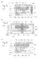
図1(A)は、振動型モータ1をモータの駆動方向(図1中D1方向)から見た状態を示す。図1(B)は、振動型モータ1をモータの駆動方向側面から見た状態を示す。振動型モータ1は、第一の部材11、第二の部材12、第三の部材13、加圧手段14を備える。
FIG. 1A shows a state in which the
第一の部材11は、交流電圧を印加することで振動する振動子111と、振動子111を保持する振動子保持部112と、振動子111と振動子保持部112を連結する連結部113と、振動子受け部114とを有する。振動子111は、例えばPZT(チタン酸ジルコン酸鉛)などの圧電効果を有する圧電素子111aと金属板111bを貼り合わせて製作される。また、振動子111には、突起部111cが設けられている。振動子保持部112には、振動型モータ1の動力を取り出す動力取り出し部112aが設けられている。
The
振動子111と振動子保持部112を連結する連結部113は、例えば薄い板金であり、板金の曲げ方向(図1中D2方向)には剛性が低く、板金の引張方向(図1中D1方向)には剛性が高い。これにより、振動子111は、図1中D2方向の振動を阻害されることなく、振動子保持部112と図1中D1方向にガタ無く連結されている。振動子受け部114は、振動子111と振動子保持部112の間に配置される。振動子受け部114には、例えばフェルトのような振動を阻害しにくい材質が用いられる。これにより、振動子の突起部111cが摩擦部材と圧接した際に、振動子111の振動を阻害せず振動子111を規定位置に保持することができる。
The connecting
第二の部材12は、金属製の摩擦部材121と摩擦部材121を保持する摩擦部材保持部材122を有する。摩擦部材121には、所定の方向(図1中D1方向)に延在し、振動子111の突起部111cに圧接される摩擦摺動面121aが設けられている。摩擦部材保持部材122には、軸形状の凸部123a、123bが設けられている。
The
第三の部材13には、第二の部材12の凸部123a、123bを保持するV溝状の保持部131a、131bが設けられている。第二の部材12の凸部123a、123bが、第三の部材13の保持部131a、131bに付勢されることにより、第三の部材13は、第二の部材12を図1中D1方向と平行な軸周り(図1中軸A1周り)に相対的に回転可能に保持する。
The
第三の部材13に凸部を設け、第二の部材12にこの凸部を保持するV溝状の保持部を設けるようにしてもよい。すなわち、本実施例の振動型アクチュエータでは、第二の部材12と第三の部材13のうちの一方には凸部が設けられ、他方には凸部を保持する保持部が設けられている。
The
図1(C)は、第一の部材11と第二の部材12と第三の部材13とを図1(A)と同様の方向から見た状態を示す。上述の保持構造により、第二の部材12は、第三の部材13に対して図1(C)中矢印R1で示すように図1中軸A1周りに相対的に回転可能である。
FIG. 1C shows a state in which the
第三の部材13には、第一の部材11を駆動方向に移動可能に保持する案内部13bとして、図1中D1方向に延在する溝が設けられている。また、第一の部材11には、第三の部材の案内部13bと対向する位置に、被案内部112bとして溝が設けられている。また、案内部13bの溝と被案内部112bの溝の間には、転動ボール15が狭持されている。これにより、第三の部材13に対し、第一の部材11は、図1中D1方向にのみ移動可能に案内される。
The
振動型モータ1は、第三の部材に対して第二の部材12を軸A1周りに回転させる力(図1中F1)を生じる加圧手段14として引張ばねを有する。以降、第三の部材に対して第二の部材12を軸A1周りに回転させる力を、第一の力と呼ぶ。加圧手段14は、第二の部材12を軸A1周りに回転させることで、振動子111の突起部111cと第二の部材12の摩擦摺動面121aを圧接する。この状態で振動子111が振動することで、突起部111cと摩擦摺動面12の間に駆動力が生じ、振動子111を有する第一の部材11は、第二の部材12に対して図1中D1方向に駆動する。
The
図6は、振動子の振動による駆動力の発生原理について説明する図である。
図6(A)は、振動子111の斜視図である。図6(B)、(C)は、それぞれ振動子111に発生させる振動モードを示す。図6(B)に示す振動モードでは、突起部111cの先端が軌跡M2で示すようにモータの図6中D1方向と平行な方向に往復運動を行う。図6(C)に示す振動モードでは、突起部111cの先端が軌跡M3で示すように図6中D2方向に往復運動を行う。図6(A)、(B)に示す2つの振動モードを適切な位相差を持たせて振動子に発生させると、突起部111cの先端は、図6(A)中、軌跡M1で示すような楕円運動を生じる。振動子の突起部111cと第二の部材12の摩擦摺動面121aが圧接された状態で、突起部111cの楕円運動が生じると、摩擦力が生じて摩擦駆動面122aに対してD1方向に駆動力を発生させる。
FIG. 6 is a diagram for explaining the principle of driving force generated by the vibration of the vibrator.
FIG. 6A is a perspective view of the
以上が振動型モータ1の構成である。振動型モータ1では、軸A1周りに回転可能に保持された第二の部材12と第三の部材13によって第一の部材11が挟まれ、摩擦摺動面121aが延在する方向と軸A1の方向と第一の部材11が第二の部材12に対して駆動する方向が平行である。
The above is the configuration of the
図2は、実施例1の振動型アクチュエータにおいて作用する力を説明する図である。
図2(A)は、第二の部材12の斜視図を示す。第二の部材12に作用する力は、ベクトルとして表現される。第二の部材12には、第一の力F1と、反力F2と、力F3、F4が作用する。第一の力F1は、加圧手段14により発生する。反力F2は、振動子111の突起部111cと摩擦摺動面121aが当接されることで発生する。力F3、F4は、第三の部材13の保持部131a、131bが、第二の部材12の凸部123a、123bを支持する力である。
FIG. 2 is a diagram illustrating the force acting on the vibration type actuator according to the first embodiment.
FIG. 2A shows a perspective view of the
図2(B)は、第二の部材12の側面図を示す。軸A1から振動子111の突起部111cと第二の部材の摩擦摺動面121aの接触点までの距離をL1、軸A1から第一の力F1の作用点までの距離をL2とすると、反力F2はF1、L1、L2を用いて、以下の式1で表される。
F2=F1×(L2/L1)・・・(式1)
FIG. 2B shows a side view of the
F2 = F1 × (L2 / L1) (Formula 1)
L2とF1は、それぞれ、軸A1と加圧手段14である引張ばねの距離、引張ばねの引張力であるので、一定である。さらに、振動子111の突起部111cと第二の部材12の摩擦摺動面121aの接触点の位置は、第一の部材の移動によって変動するが、第一の部材の移動方向が軸A1と平行であるので、第一の部材が移動してもL1は変化しない。以上により、第一の部材が移動した場合でもF1、L1、L2が一定であるので、反力F2は一定である。
L2 and F1 are constant because they are the distance between the axis A1 and the tension spring which is the pressurizing means 14, and the tension force of the tension spring, respectively. Further, the position of the contact point between the
図2(C)は、第一の部材11が移動した場合のF1、F2、F3、F4の変動を表す図である。第一の部材21のD1方向の位置をXとし、F1を実線、F2を破線、F3を一点鎖線、F4を二点鎖線で表している。第一の部材がD1方向に移動した時、F3、F4は変動するが、前述の通りF2は一定である。反力F2の大きさは、振動子111の突起部111cと摩擦摺動面121aが圧接される加圧力と同等であるので、突起部111cと摩擦摺動面121aを圧接する加圧力は、第一の部材11が移動した場合でも、一定である。
FIG. 2C is a diagram illustrating fluctuations in F1, F2, F3, and F4 when the
振動型モータ1では、摩擦部材121を有する第二の部材12が、第三の部材13に保持されているので、摩擦部材121が傾倒することは無い。また、第一の部材が移動した時でも、その移動量に関わらず振動子の突起部111cと摩擦摺動面121aを当接させる加圧力は一定である。したがって、振動型モータ1は、振動子が大きなストローク量移動した場合でも、駆動特性が安定している。
In the
本発明の適用範囲は、振動型モータ1に限定されない。本発明は、例えば各部材の形状、材質等が振動型モータ1とは異なる振動型アクチュエータに適用可能である。また、振動子111に発生させる振動モードも、図6を参照して説明した振動モードである必要はない。
The application range of the present invention is not limited to the
振動型モータ1では、第三の部材13が第一の部材11を駆動方向にのみ移動可能に保持する案内部13bを有しているが、必ずしも案内部13bを第三の部材13に備える必要はない。例えば、振動型モータ1を固定する不図示の筐体に案内部を設けても良い。ただし、第三の部材13以外の部材に別途案内部を設ける場合は振動型モータの大型化が生じるため、第三の部材13が案内部を有することが好ましい。
In the
また、振動型モータ1は、第一の部材11が、振動型モータ1の動力を取り出す動力取り出し部112aを有する。この構成においては、第一の部材11または第二の部材12を不図示の筐体に固定し、不図示の駆動対象に動力取り出し部112aを連結し、第一の部材11の移動により駆動対象の駆動を行う。必ずしも動力取り出し部を第一の部材11に備える必要はないが、動力取り出し部を第二の部材12または第三の部材13に備えた場合は、第一の部材11が筐体に固定され、第二の部材12と第三の部材13の移動により駆動対象の駆動を行う。この場合は、駆動方向に長い第二の部材12と第三の部材13が移動することで筐体内において大きな体積を占めることとなってしまう。以上により、第一の部材11が、動力取り出し部112aを有することが好ましい。
Further, in the
また、振動型モータ1では、凸部123a、123bがV溝状の保持部131a、131bに付勢されることで、第三の部材13が第二の部材12を軸A1周りに相対的に回転可能に保持するが、保持部131a、131bは必ずしもV溝状である必要はない。例えば、保持部131a、131bが穴であり、穴に凸部123a、123bの軸を嵌合させることでも本発明の効果を得ることができる。
Further, in the
また、振動型モータ1では、第一の力F1により第二の部材12と第三の部材13が第一の部材11を挟んだ時に、凸部123a、123bが、保持部131a、131bによりF3、F4の力で保持される。凸部123a、123bと保持部131a、131bは、F3、F4の力で付勢される。この時、第二の部材12は、図2中D2方向にガタがなく、安定して振動子111の突起部111cと摩擦摺動面121aを圧接することができる。以上により、凸部123a、123bが、保持部131a、131に付勢されることで、第三の部材13が第二の部材12を軸A1周りに相対的に回転可能に保持することが好ましい。
Further, in the
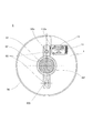
図7は、実施例1の振動型モータを備えるレンズ駆動装置をレンズの光軸方向から見た図である。
レンズ駆動装置9は、レンズ91、レンズホルダ92、2つの案内部材93、筐体94、振動型モータ1を備える。レンズ91は、例えばカメラのレンズ鏡筒に用いられるフォーカスレンズであり、光軸A2方向に移動することで光学系の焦点位置を調整する。レンズホルダ92は、レンズ91を保持しており、光軸A2方向に貫通した丸穴部92aと長穴部92bを有している。2つの案内部材93は、例えば円柱状のガイドバーであり、光軸A2と平行な方向に延在し両端部が筐体94に固定されている。案内部材93は、それぞれ、レンズホルダ92の丸穴部92a、長穴部92bと嵌合し、レンズホルダ92とレンズ91を光軸A2方向にのみ移動可能に保持している。
FIG. 7 is a diagram of the lens driving device including the vibration type motor according to the first embodiment as viewed from the optical axis direction of the lens.
The lens driving device 9 includes a
振動型モータ1は、第三の部材13が筐体94に固定され、モータの駆動方向が光軸A2と平行となるように配置される。振動型モータ1の動力取り出し部112aは、レンズホルダ92に連結されている。振動型モータ1を駆動すると、振動型モータ1の第一の部材11が、光軸A2方向に駆動し、第一の部材11と動力取り出し部112aを介して連結されたレンズ91、レンズホルダ92が光軸A2方向に駆動される。
The
レンズ駆動装置9の作用および効果について述べる。レンズ駆動装置9では、レンズ91の駆動に振動型モータ1を用いている。振動型モータ1は、大きなストローク量でも安定した駆動特性を実現しているため、レンズ91とレンズホルダ92を大きなストローク量でも安定して駆動することが可能になる。
The operation and effect of the lens driving device 9 will be described. In the lens driving device 9, the
(実施例2)
図3は、実施例2の振動型アクチュエータの構成を示す図である。
図1に示す振動型モータ2は、高周波電圧を印加することで超音波振動する振動子を有する振動型アクチュエータである超音波モータである。もちろん、本発明の適用範囲は、超音波モータに限定されない。また、本発明は、振動型モータ2を備えるレンズ駆動装置に適用可能である。
(Example 2)
FIG. 3 is a diagram illustrating a configuration of the vibration actuator according to the second embodiment.
A
図3(A)は、振動型モータ2をモータの駆動方向(図3中D1方向)から見た状態を示す。図3(B)は、振動型モータ2をモータの駆動方向側面から見た状態を示す。図3(C)は、振動型モータ2を図3(B)中の矢印Pで示す方向に見た状態を示す。振動型モータ2は、第一の部材21、第二の部材22、第三の部材23と加圧手段24とを備える。
FIG. 3A shows a state in which the
第一の部材21は、振動子211、振動子保持部212、連結部213、振動子受け部214を有する。振動子211は、圧電素子211a、金属板211b、突起部211cを有する。振動子保持部212は、振動型モータ2の動力を取り出す動力取り出し部212aを有する。
The
第二の部材22は、摩擦部材221と摩擦部材保持部材222を有する。摩擦部材221は、摩擦摺動面221aを備える。摩擦部材保持部材222には、凸部223a、223bが設けられている。第三の部材23には、保持部231a、231bが設けられている。各部材の詳細は、実施例1と同様であるので、省略する。また、第二の部材22の凸部223a、223bと第三の部材の保持部231a、231bが付勢されることで、第三の部材23が第二の部材22を軸A1周りに相対的に回転可能に保持している。
The
第三の部材23に設けられた案内部13bと第一の部材21に設けられた被案内部112bと転動ボール15により、第三の部材23に対して第一の部材22は図3中D1方向にのみ移動可能に案内される。
3 with respect to the
振動型モータ2は、第三の部材に対して第二の部材12を軸A1周りに回転させる第一の力(図3中F1a)を生じる加圧手段24として機能する引張ばねを備える。加圧手段24である引張ばねは、図3(B)に示すように斜めに掛けられており、第一の力F1aに加えて図3中D1方向にも力(図3中F1b)を生じる。D1方向の力は、第三の部材23に対し第二の部材22をモータの駆動方向であるD1方向に付勢する。以降、この第三の部材23に対し第二の部材22をモータの駆動方向つまり第二の部材が延在する方向に付勢する力を、第二の力と呼ぶ。
The
第一の力F1は、実施例1と同様に、第二の部材22を軸A1周りに回転させることで振動子211の突起部211cと第二の部材22の摩擦摺動面221aを圧接する。この状態で振動子211が振動すると、前述の原理で駆動力が生じ、振動子211を有する第一の部材21は第二の部材22に対して図3中D1方向に駆動する。また、第二の力F1bは、第二の部材22と第三の部材23の間に図3中F5で示す偶力を生じさせる。
As in the first embodiment, the first force F1 presses the
図5を参照して、第三の部材の保持部の形状を説明する。保持部231a、231bは、それぞれ第一の面S1、第二の面S2を有し、それぞれの面は所定の角度となるよう形成される。第一の面S1、第二の面S2の作用については後述する。第一の面S1と第二の面S2が、凸部223a、223bと接触することで凸部223a、223bと保持部231a、231bが規定の位置に配置される。
The shape of the holding part of the third member will be described with reference to FIG. The holding
以上が振動型モータ2の構成である。振動型モータ2では、振動型モータ1と同様に、軸A1周りに回転可能に保持された第二の部材22と第三の部材23によって第一の部材21が挟まれる。そして、摩擦摺動面221aが延在する方向と軸A1の方向と第一の部材21が第二の部材22に対して駆動する方向が略平行である。さらに、振動型モータ2では、加圧手段24が第一の力F1aに加えて第二の力F1bを生じ、第二の力F1bは第二の部材22と第三の部材23の間に偶力F5を生じる。
The above is the configuration of the
図4は、実施例2の振動型アクチュエータにおいて作用する力を説明する図である。
図4(A)は、第二の部材22の斜視図を示す。第二の部材22に作用する力は、ベクトルとして表現される。第二の部材22には、第一の力F1a、第二の力F1b、反力F2、力F3、F4が作用する。第一の力F1a、第二の力F1bは、加圧手段24によって発生する。反力F2は、振動子211の突起部211cと摩擦摺動面221aが当接されることにより発生する。力F3、F4は、第三の部材23の保持部231a、231bが第二の部材12の凸部223a、223bを支持する力であり、保持部231a、231bの凸部222aへの付勢力でもある。
FIG. 4 is a diagram illustrating the force acting on the vibration type actuator of the second embodiment.
FIG. 4A shows a perspective view of the
F3、F4は、それぞれF3aとF3b、F4aとF4bに分解することができる。F3a、F4aは、第一の力F1aにより第二の部材22と第三の部材23が第一の部材21を挟んだ時に生じる付勢力である。F3b、F4bは、第二の力F1bが生じる偶力(図4中F5)によって第二の部材22が回転することを防ぐため、保持部231a、231bが凸部223a、223bに与える付勢力である。以降、第一の力F1aにより第二の部材22と第三の部材23が第一の部材21を挟んだ時に生じる付勢力F3a、F4aを第一の付勢力と呼ぶ。また、偶力F5による付勢力F3b、F4bを、第二の付勢力と呼ぶ。
F3 and F4 can be decomposed into F3a and F3b, and F4a and F4b, respectively. F3a and F4a are urging forces generated when the
図4(B)は、第二の部材12の側面図を示す。
実施例1と同様に、反力F2はF1、L1、L2を用いて、以下の式1で表される。
F2=F1×(L2/L1)・・・(式1)
FIG. 4B shows a side view of the
Similar to the first embodiment, the reaction force F2 is expressed by the following
F2 = F1 × (L2 / L1) (Formula 1)
L2とF1は一定である。さらに、第一の部材21の移動方向が軸A1と平行であるので、第一の部材21が移動してもL1は変化しない。以上により、第一の部材21が移動した場合でもF1、L1、L2が一定であるので、反力F2は一定である。反力F2が、第一の部材21が移動した場合でも一定であるので、突起部211cと摩擦摺動面221aを圧接する加圧力も第一の部材21が移動した場合も一定である。また、第二の力F1bは一定であるので、第二の力F1bが生じる偶力F5による第二の付勢力F3b、F4bは一定である。
L2 and F1 are constant. Furthermore, since the moving direction of the
図4(C)は、第一の部材21が移動した場合のF1、F2、F3、F4の変動を示す。第一の部材21のD1方向の位置をXとし、F1を実線、F2を破線、F3を一点鎖線、F4を二点鎖線で表している。実施例1と同様に、F1、F2は一定である。第三の部材13の保持部231a、231bと第二の部材22の凸部223a、223bの付勢力F3、F4は、変動するが、第二の付勢力F3b、F4bが一定であるので、必ず一定以上の付勢力となる。また、第一の部材が移動すると第一の付勢力F3a、F3b、第二の付勢力F4a、F4bの比が変化するので、付勢力F3、F4の方向が変化する。
FIG. 4C shows fluctuations in F1, F2, F3, and F4 when the
図5は、付勢力F3、F4が変動した場合における、第三の部材保持部による第二の部材の凸部の保持を説明する図である。
図5(A),(B)は、第一の部材21が一方の駆動端(負のX方向端)まで移動した時の凸部223aと保持部231aの拡大図である。図5(C),(D)は、第一の部材21が他方の駆動端(正のX方向端)まで移動した時の凸部223bと保持部231bの拡大図である。図5(A)におけるF3の方向を第一の方向(図5(A)中D4方向)と呼ぶ。また、図5(C)におけるF3の方向を第二の方向(図5(C)中D5方向)と呼ぶ。また、保持部231aの第一の面S1、第二の面S2の法線をN1、N2とする。
FIG. 5 is a diagram illustrating the holding of the convex portion of the second member by the third member holding portion when the urging forces F3 and F4 vary.
FIGS. 5A and 5B are enlarged views of the
保持部231aが凸部223aに対して付勢される付勢力F3が、法線N1と法線N2の為す角度の外側を向く場合は、凸部223aが第一の面S1または第二の面S2上を保持部231aから外れる方向に滑り、凸部223aと保持部231aが外れてしまう。振動型モータ2では、法線N1に対し第一の方向が為す角(図5(A),(C)中θ1)と第二の方向が為す角(図5(A),(C)中θ2)は、法線N2が為す角(図5(A),(C)中θ3)より小さくなっている。これにより、付勢力F3が変動しても、第一の面S1と第二の面S2によって凸部223aと保持部231aは外れることなく付勢される。
When the urging force F3 urging the holding
また、図5(B)におけるF4の方向を第一の方向(図5(B)中D4方向)と呼ぶ。図5(D)におけるF4の方向を第二の方向(図5(D)中D5方向)と呼ぶ。保持部231bの第一の面S1、第二の面S2の法線を、それぞれN1、N2とする。法線N1に対して第一の方向が為す角θ1と第二の方向が為す角θ2は、法線N1に対して法線N2が為す角θ3より小さい。付勢力F4が変動しても、第一の面S1と第二の面S2によって凸部223bと保持部231aは外れることなく付勢される。
Further, the direction of F4 in FIG. 5B is referred to as a first direction (D4 direction in FIG. 5B). The direction of F4 in FIG. 5D is referred to as a second direction (D5 direction in FIG. 5D). The normal lines of the first surface S1 and the second surface S2 of the holding
以上説明した振動型モータ2では、振動子が大きなストローク量移動した場合でも駆動特性が安定する。なお、振動型モータ2は、各部材の形状、材質は必ずしも振動型モータ2と同様である必要はない。振動子211に発生させる振動モードも、図6を参照して説明した振動モードである必要はない。
In the
振動型モータ2が備える加圧手段24は、第一の力F1aに加え第三の部材23の部材に対し第二の部材22をモータの駆動方向に付勢する第二の力F1bを生じる。これにより、部品を増やすことなく第二の部材22と第三の部材23のモータの駆動方向(図4中D1方向)のガタをとることができる。
In addition to the first force F1a, the pressurizing means 24 included in the
また、振動型モータ2では、第二の力F1bに加え第二の部材22と第三の部材23の間に偶力F5を生じる。そして、凸部223a、223bと保持部231a、231bは、第一の付勢力F3a、F4aと第二の付勢力F3b、F4bの合力である付勢力F3、F4により付勢される。第二の付勢力F3b、F4bは、一定であり、F3、F4は、第一の部材が移動した場合でも常に一定以上の付勢力を得ることができる。このため、第一の部材が大きなストローク量移動した場合であっても、図4中D2方向にガタがなく、安定して振動子211の突起部211cと摩擦摺動面221aを圧接することができる。
In addition, in the
また、振動型モータ2では、第一の法線N1に対し第一の方向D4、第二の方向D5が為す角度θ1、θ2は、第二の法線N2が為す角度θ3以下である。これにより、凸部223a、223bと保持部231a、231bの付勢力F3、F4が変動した場合でも凸部223a、223bと保持部231a、231bが外れない。
In the
なお、必ずしも案内部23bを第三の部材23に備える必要はないが、第三の部材13が案内部を有することが好ましい。また、必ずしも動力取り出し部を第一の部材に備える必要はないが、第一の部材が動力取り出し部を有することが好ましいことは第一の実施形態と同様である。また、保持部231a、231bは必ずしもV溝状である必要はないことは実施例1と同様である。なお、振動型モータ2を用いたレンズ駆動装置の作用および効果については、実施例1と同様である。
In addition, although it is not always necessary to provide the
1 振動型モータ
11 第一の部材
12 第二の部材
13 第三の部材
DESCRIPTION OF
Claims (9)
所定の方向に延在し、前記振動子に圧接される摩擦摺動面を有する第二の部材と、
前記第一の部材と前記第二の部材とが前記所定の方向と平行な軸周りに相対的に回転可能に保持する第三の部材と、
前記第三の部材に対して前記第二の部材を前記軸周りに相対的に回転させる第一の力を発生する加圧手段を備え、
前記第一の部材は、前記第一の力によって、前記第二の部材と前記第三の部材とに狭まれ、
前記振動子が振動することで、前記第一の部材が、第二の部材に対して前記所定の方向と平行な駆動方向に駆動する
ことを特徴とする振動型アクチュエータ。 A first member having a vibrator;
A second member extending in a predetermined direction and having a friction sliding surface pressed against the vibrator;
A third member and said first member and said second member is relatively rotatably held in the predetermined direction parallel to the axis around
Includes a pressurizing means for generating a first force for relatively rotating the second member about said axis relative to said third member,
The first member is narrowed to the second member and the third member by the first force,
The vibration type actuator, wherein the first member is driven in a driving direction parallel to the predetermined direction with respect to the second member by the vibration of the vibrator.
ことを特徴とする請求項1に記載の振動型アクチュエータ。 The vibration type actuator according to claim 1, wherein the third member includes a guide portion that holds the first member so as to be movable in the driving direction.
ことを特徴とする請求項1または請求項2に記載の振動型アクチュエータ。 3. The vibration type actuator according to claim 1, wherein the first member includes a power take-out unit that takes out power of the vibration type actuator.
前記凸部と前記保持部とが付勢されることで、前記第三の部材が、前記第二の部材を前記軸周りに相対的に回転可能に保持する
ことを特徴とする請求項1乃至3のいずれか1項に記載の振動型アクチュエータ。 One of the second member and the third member is provided with a convex portion, and the other is provided with a holding portion for holding the convex portion,
The third member holds the second member so as to be relatively rotatable about the axis by urging the convex portion and the holding portion. 4. The vibration type actuator according to any one of 3 above.
請求項1乃至請求項4のいずれか1項に記載の振動型アクチュエータ。 The said pressurization means further generate | occur | produces the 2nd force which urges | biases said 2nd member to the said predetermined direction with respect to said 3rd member. Vibration type actuator.
前記凸部と前記保持部とは、前記第一の力により前記第二の部材と前記第三の部材が前記第一の部材を挟んだ時に生じる第一の付勢力と、前記偶力による第二の付勢力との合力により付勢される
ことを特徴とする請求項5に記載の振動型アクチュエータ。 The second force causes a couple between the second member and the third member,
The convex portion and the holding portion include a first biasing force generated when the second member and the third member sandwich the first member by the first force, and a first biasing force generated by the couple. The vibration type actuator according to claim 5, wherein the vibration type actuator is biased by a resultant force of the second biasing force.
前記第一の面の法線を第一の法線、前記第二の面の法線を第二の法線とし、前記第一の部材が一方の駆動端に移動した時の前記合力の方向を第一の方向、他方の駆動端に移動した時の前記合力の方向を第二の方向としたとき、第一の法線に対して第一の方向、第二の方向がなす角度は、第一の法線に対して第二の法線がなす角度より小さい
ことを特徴とする請求項6に記載の振動型アクチュエータ。 The holding portion has a first surface and a second surface that come into contact with the convex portion,
The normal direction of the first surface is the first normal line, the normal line of the second surface is the second normal line, and the direction of the resultant force when the first member moves to one drive end Is the first direction, and the direction of the resultant force when moving to the other drive end is the second direction, the angle between the first direction and the second direction with respect to the first normal is The vibration type actuator according to claim 6, wherein the vibration type actuator is smaller than an angle formed by the second normal line with respect to the first normal line.
ことを特徴とする請求項1乃至7のいずれか1項に記載の振動型アクチュエータとして機能する超音波モータ。 The ultrasonic motor that functions as the vibration type actuator according to claim 1, wherein the vibrator vibrates ultrasonically by an applied voltage.
Priority Applications (5)
| Application Number | Priority Date | Filing Date | Title |
|---|---|---|---|
| JP2015122190A JP6570335B2 (en) | 2015-06-17 | 2015-06-17 | Vibration type actuator, lens driving device and ultrasonic motor |
| CN201680033778.XA CN107615637B (en) | 2015-06-17 | 2016-06-10 | Vibratory actuator, lens driver and ultrasonic motor |
| PCT/JP2016/002807 WO2016203745A1 (en) | 2015-06-17 | 2016-06-10 | Vibration type actuator, lens driving device, and ultrasonic motor |
| EP16811220.9A EP3311479A4 (en) | 2015-06-17 | 2016-06-10 | Vibration type actuator, lens driving device, and ultrasonic motor |
| US15/562,679 US10574156B2 (en) | 2015-06-17 | 2016-06-10 | Vibration type actuator, lens driving device, and ultrasonic motor |
Applications Claiming Priority (1)
| Application Number | Priority Date | Filing Date | Title |
|---|---|---|---|
| JP2015122190A JP6570335B2 (en) | 2015-06-17 | 2015-06-17 | Vibration type actuator, lens driving device and ultrasonic motor |
Publications (3)
| Publication Number | Publication Date |
|---|---|
| JP2017011797A JP2017011797A (en) | 2017-01-12 |
| JP2017011797A5 JP2017011797A5 (en) | 2018-07-26 |
| JP6570335B2 true JP6570335B2 (en) | 2019-09-04 |
Family
ID=57545115
Family Applications (1)
| Application Number | Title | Priority Date | Filing Date |
|---|---|---|---|
| JP2015122190A Active JP6570335B2 (en) | 2015-06-17 | 2015-06-17 | Vibration type actuator, lens driving device and ultrasonic motor |
Country Status (5)
| Country | Link |
|---|---|
| US (1) | US10574156B2 (en) |
| EP (1) | EP3311479A4 (en) |
| JP (1) | JP6570335B2 (en) |
| CN (1) | CN107615637B (en) |
| WO (1) | WO2016203745A1 (en) |
Families Citing this family (7)
| Publication number | Priority date | Publication date | Assignee | Title |
|---|---|---|---|---|
| JP2019195233A (en) | 2018-05-01 | 2019-11-07 | キヤノン株式会社 | Vibration wave motor and driving unit with the vibration wave motor |
| JP7112250B2 (en) | 2018-05-24 | 2022-08-03 | キヤノン株式会社 | Oscillating wave motor and drive |
| JP7094792B2 (en) | 2018-06-20 | 2022-07-04 | キヤノン株式会社 | Vibration wave motor and drive |
| JP6852033B2 (en) * | 2018-10-03 | 2021-03-31 | キヤノン株式会社 | Vibration type actuators and devices |
| JP7313909B2 (en) * | 2019-05-30 | 2023-07-25 | キヤノン株式会社 | vibration wave motors and electronics. |
| JP7258675B2 (en) | 2019-06-24 | 2023-04-17 | キヤノン株式会社 | Vibrating motors and optical equipment |
| JP7258674B2 (en) | 2019-06-24 | 2023-04-17 | キヤノン株式会社 | Vibrating motors, lens devices, and electronic devices |
Family Cites Families (7)
| Publication number | Priority date | Publication date | Assignee | Title |
|---|---|---|---|---|
| JP3437225B2 (en) | 1993-09-30 | 2003-08-18 | オリンパス光学工業株式会社 | Ultrasonic actuator |
| JP4521165B2 (en) * | 2003-08-06 | 2010-08-11 | オリンパス株式会社 | Vibration wave linear motor |
| JP4997774B2 (en) * | 2005-03-30 | 2012-08-08 | コニカミノルタアドバンストレイヤー株式会社 | Drive device |
| JP2010141973A (en) * | 2008-12-09 | 2010-06-24 | Olympus Corp | Ultrasonic motor |
| JP6110630B2 (en) * | 2012-11-04 | 2017-04-05 | キヤノン株式会社 | Ultrasonic motor and device driving apparatus with ultrasonic motor |
| JP6271963B2 (en) * | 2013-11-21 | 2018-01-31 | キヤノン株式会社 | Vibration type actuator |
| JP6448310B2 (en) | 2014-10-30 | 2019-01-09 | キヤノン株式会社 | Vibrator and ultrasonic motor |
-
2015
- 2015-06-17 JP JP2015122190A patent/JP6570335B2/en active Active
-
2016
- 2016-06-10 US US15/562,679 patent/US10574156B2/en not_active Expired - Fee Related
- 2016-06-10 WO PCT/JP2016/002807 patent/WO2016203745A1/en active Application Filing
- 2016-06-10 EP EP16811220.9A patent/EP3311479A4/en not_active Withdrawn
- 2016-06-10 CN CN201680033778.XA patent/CN107615637B/en active Active
Also Published As
| Publication number | Publication date |
|---|---|
| US20180097459A1 (en) | 2018-04-05 |
| CN107615637B (en) | 2019-09-10 |
| WO2016203745A1 (en) | 2016-12-22 |
| JP2017011797A (en) | 2017-01-12 |
| CN107615637A (en) | 2018-01-19 |
| EP3311479A4 (en) | 2019-02-20 |
| US10574156B2 (en) | 2020-02-25 |
| EP3311479A1 (en) | 2018-04-25 |
Similar Documents
| Publication | Publication Date | Title |
|---|---|---|
| JP6570335B2 (en) | Vibration type actuator, lens driving device and ultrasonic motor | |
| JP4509084B2 (en) | Lens transfer device | |
| US11303228B2 (en) | Driving device, optical device, and image pickup device | |
| JP2007185056A (en) | Exciting method of elastic vibration body, and vibration drive device | |
| JP5683643B2 (en) | Linear ultrasonic motor and optical apparatus having the same | |
| US9964731B2 (en) | Vibration type motor, and lens drive apparatus, lens unit and image pickup apparatus using vibration type motor | |
| US10804820B2 (en) | Motor and apparatus using the same | |
| JP6122452B2 (en) | Actuator | |
| US20180183355A1 (en) | Vibration-wave motor and apparatus using the same | |
| JP6422248B2 (en) | Driving device and lens driving device having the same | |
| JP6605012B2 (en) | Vibration wave motor and lens driving device using vibration wave motor | |
| US10924037B2 (en) | Vibration motor that prevents resonance of contact member, and electronic apparatus | |
| US10439518B2 (en) | Vibration-type actuator, driving method for vibration-type actuator, and electronic apparatus equipped with vibration-type actuator | |
| JP6708472B2 (en) | Vibration wave motor and optical device equipped with the vibration wave motor | |
| CN109980986A (en) | Vibration types of motors, lens apparatus and electronic device | |
| JP2019126161A (en) | Vibration wave motor and lens driving device using vibration wave motor | |
| JP2004274916A (en) | Actuator | |
| JP7094799B2 (en) | Vibration type motor and drive | |
| JP2012151924A (en) | Vibrator retention mechanism, vibration motor and lens drive device | |
| JP2016027780A (en) | Vibration type actuator, lens barrel, imaging device, and automatic stage | |
| JP6929165B2 (en) | Vibration wave motor and drive | |
| JP2016101023A (en) | Vibration wave motor and optical device including the same | |
| JP6624859B2 (en) | Vibration wave motor | |
| JP2020102971A (en) | Vibration wave motor | |
| JP2017200355A (en) | Vibration wave motor and electronic apparatus mounting vibration wave motor |
Legal Events
| Date | Code | Title | Description |
|---|---|---|---|
| A521 | Written amendment |
Free format text: JAPANESE INTERMEDIATE CODE: A523 Effective date: 20180613 |
|
| A621 | Written request for application examination |
Free format text: JAPANESE INTERMEDIATE CODE: A621 Effective date: 20180613 |
|
| TRDD | Decision of grant or rejection written | ||
| A01 | Written decision to grant a patent or to grant a registration (utility model) |
Free format text: JAPANESE INTERMEDIATE CODE: A01 Effective date: 20190709 |
|
| A61 | First payment of annual fees (during grant procedure) |
Free format text: JAPANESE INTERMEDIATE CODE: A61 Effective date: 20190806 |
|
| R151 | Written notification of patent or utility model registration |
Ref document number: 6570335 Country of ref document: JP Free format text: JAPANESE INTERMEDIATE CODE: R151 |