JP2010141973A - Ultrasonic motor - Google Patents
Ultrasonic motor Download PDFInfo
- Publication number
- JP2010141973A JP2010141973A JP2008313569A JP2008313569A JP2010141973A JP 2010141973 A JP2010141973 A JP 2010141973A JP 2008313569 A JP2008313569 A JP 2008313569A JP 2008313569 A JP2008313569 A JP 2008313569A JP 2010141973 A JP2010141973 A JP 2010141973A
- Authority
- JP
- Japan
- Prior art keywords
- ultrasonic motor
- piezoelectric element
- pressing
- holding member
- housing
- Prior art date
- Legal status (The legal status is an assumption and is not a legal conclusion. Google has not performed a legal analysis and makes no representation as to the accuracy of the status listed.)
- Pending
Links
Images


Classifications
-
- H—ELECTRICITY
- H02—GENERATION; CONVERSION OR DISTRIBUTION OF ELECTRIC POWER
- H02N—ELECTRIC MACHINES NOT OTHERWISE PROVIDED FOR
- H02N2/00—Electric machines in general using piezoelectric effect, electrostriction or magnetostriction
- H02N2/02—Electric machines in general using piezoelectric effect, electrostriction or magnetostriction producing linear motion, e.g. actuators; Linear positioners ; Linear motors
- H02N2/026—Electric machines in general using piezoelectric effect, electrostriction or magnetostriction producing linear motion, e.g. actuators; Linear positioners ; Linear motors by pressing one or more vibrators against the driven body
-
- H—ELECTRICITY
- H02—GENERATION; CONVERSION OR DISTRIBUTION OF ELECTRIC POWER
- H02N—ELECTRIC MACHINES NOT OTHERWISE PROVIDED FOR
- H02N2/00—Electric machines in general using piezoelectric effect, electrostriction or magnetostriction
- H02N2/0005—Electric machines in general using piezoelectric effect, electrostriction or magnetostriction producing non-specific motion; Details common to machines covered by H02N2/02 - H02N2/16
- H02N2/001—Driving devices, e.g. vibrators
- H02N2/003—Driving devices, e.g. vibrators using longitudinal or radial modes combined with bending modes
- H02N2/004—Rectangular vibrators
-
- H—ELECTRICITY
- H02—GENERATION; CONVERSION OR DISTRIBUTION OF ELECTRIC POWER
- H02N—ELECTRIC MACHINES NOT OTHERWISE PROVIDED FOR
- H02N2/00—Electric machines in general using piezoelectric effect, electrostriction or magnetostriction
- H02N2/0005—Electric machines in general using piezoelectric effect, electrostriction or magnetostriction producing non-specific motion; Details common to machines covered by H02N2/02 - H02N2/16
- H02N2/005—Mechanical details, e.g. housings
- H02N2/0055—Supports for driving or driven bodies; Means for pressing driving body against driven body
- H02N2/006—Elastic elements, e.g. springs
-
- H—ELECTRICITY
- H10—SEMICONDUCTOR DEVICES; ELECTRIC SOLID-STATE DEVICES NOT OTHERWISE PROVIDED FOR
- H10N—ELECTRIC SOLID-STATE DEVICES NOT OTHERWISE PROVIDED FOR
- H10N30/00—Piezoelectric or electrostrictive devices
- H10N30/20—Piezoelectric or electrostrictive devices with electrical input and mechanical output, e.g. functioning as actuators or vibrators
- H10N30/202—Piezoelectric or electrostrictive devices with electrical input and mechanical output, e.g. functioning as actuators or vibrators using longitudinal or thickness displacement combined with bending, shear or torsion displacement
- H10N30/2023—Piezoelectric or electrostrictive devices with electrical input and mechanical output, e.g. functioning as actuators or vibrators using longitudinal or thickness displacement combined with bending, shear or torsion displacement having polygonal or rectangular shape
Landscapes
- General Electrical Machinery Utilizing Piezoelectricity, Electrostriction Or Magnetostriction (AREA)
Abstract
Description
この発明は、例えばデジタルカメラの手振れ補正ユニットやAFレンズ等のアクチュエータとして用いられている超音波モータに関する。 The present invention relates to an ultrasonic motor used as an actuator such as a camera shake correction unit or an AF lens of a digital camera.
一般に、この種の超音波モータは、振動子である圧電素子に電圧を印加して縦振動と屈曲振動を励起させて楕円振動を発生させ、この楕円振動を、摩擦接触子を介して被駆動体に伝達し、該被駆動体を摩擦駆動するように構成されている。 In general, this type of ultrasonic motor applies elliptical vibration and bending vibration by applying a voltage to a piezoelectric element as a vibrator to generate elliptical vibration, and this elliptical vibration is driven via a friction contact. It is configured to transmit to the body and frictionally drive the driven body.
このような圧電素子を用いる超音波モータとしては、振動子の突起を、レール上に移動可能に載置して、その上面に押圧手段を構成するばね部材を、ゴムシート及び固定板を用いて挟装配置し、このばね部材のばね力で振動子の突起をレール上に摩擦駆動可能に押圧配置した構成のものが提案されている(例えば、特許文献1参照。)。これにより、振動子で楕円振動が発生すると、ばね部材のばね力により、その駆動力がレールに伝達され、該レールが回転部材を介して駆動される。
しかしながら、上記特許文献1に開示される構成では、振動子に対して押圧手段を構成するばね部材、ゴムシート、固定板を、順に組付け配置する構成のために、その組立作業時、ばね部材の初期ばね力を調整しながら各部品を順に組付けていかなければならないことにより、その作業が非常に面倒であるという問題を有する。 However, in the configuration disclosed in Patent Document 1, the spring member, the rubber sheet, and the fixing plate that constitute the pressing means with respect to the vibrator are sequentially assembled and arranged, so that during the assembly operation, the spring member Since it is necessary to assemble the parts in order while adjusting the initial spring force, the operation is very troublesome.
この発明は上記の事情に鑑みてなされたもので、簡易な構成で、且つ、簡便にして容易な組立作業を実現し得るようにした超音波モータを提供することを目的とする。 The present invention has been made in view of the above circumstances, and an object thereof is to provide an ultrasonic motor having a simple configuration and capable of realizing an easy and easy assembly operation.
この発明の超音波モータは、圧電素子と、前記圧電素子に設けられ、前記駆動力を前記被駆動体に伝達する摩擦接触子と、前記圧電素子に設けられ、筐体に位置決め保持される保持部材と、前記保持部材に一体成形され、前記圧電素子の摩擦接触子を前記被駆導体に摩擦駆動可能に押圧する押圧部材と、前記押圧部材に付与する前記被駆動体に対する押圧力を調整する押圧調整機構とを備えて構成した。 The ultrasonic motor of the present invention includes a piezoelectric element, a friction contact provided on the piezoelectric element and transmitting the driving force to the driven body, and a holding provided on the housing and positioned on the housing. A member, a pressing member that is integrally formed with the holding member, presses the friction contact of the piezoelectric element against the driven conductor so as to be frictionally driven, and adjusts the pressing force applied to the driven body applied to the pressing member. And a pressing adjustment mechanism.
上記構成によれば、圧電素子は、保持部材が取付けられると、該保持部材に一体成形された押圧部材が所望のばね性を持たせて筐体内に組付け配置される。これにより、押圧部材の保持部材への初期ばね力設定を伴う組付け作業を行うことが無くなり、モータ組立作業の簡略化を図ることが可能となる。 According to the above configuration, when the holding member is attached to the piezoelectric element, the pressing member integrally formed with the holding member is assembled and disposed in the housing with a desired spring property. As a result, it is not necessary to perform an assembling operation that involves setting an initial spring force on the holding member of the pressing member, and the motor assembling operation can be simplified.
以上述べたように、この発明によれば、簡易な構成で、且つ、簡便にして容易な組立作業を実現し得るようにした超音波モータを提供することができる。 As described above, according to the present invention, it is possible to provide an ultrasonic motor that has a simple configuration and that can easily and easily realize an assembling operation.
以下、この発明の実施の形態について、図面を参照して詳細に説明する。 Hereinafter, embodiments of the present invention will be described in detail with reference to the drawings.
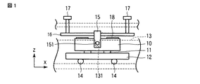
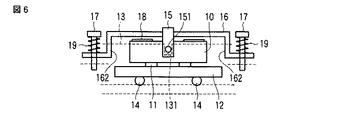
図1は、この発明の一実施の形態に係る超音波モータを示すもので、圧電素子10は、例えば複数の電極板が積層されて矩形状に形成され、各電極に電圧が印加されると、縦振動及び屈曲振動を同時に励起して楕円振動を発生させる。
FIG. 1 shows an ultrasonic motor according to an embodiment of the present invention. A
この圧電素子10には、その下面の、例えば屈曲振動の腹に対応して摩擦接触子11が接着剤を用いて所定の間隔に固着され、この摩擦接触子11は、被駆動体12に接触されている(図2参照)。この被駆動体12は、筐体13にボール等の転動部材14を介して矢印X方向に移動自在に設けられている。
A
また、圧電素子10には、その縦振動の節に対応する、例えば上面を含む3面を囲んで略コ字形状の保持部材15が、例えば接着剤を用いて固着されている。この保持部材15は、例えば樹脂材料で形成され、上面側に例えば金属材料製の押圧部材である板状のばね部材16の中間部が、インサート成形により一体成形されて上記圧電素子10の長手方向に沿って組付け配置されている。
In addition, a substantially U-shaped
このばね部材16は、その両端部に押圧調整機構を構成する螺子部材17が配置される。この螺子部材17は、上記筐体13に螺合調整自在に設けられ、その螺合調整により上記ばね部材16の撓み量を調整して保持部材15を介して圧電素子10に付与する押圧力を設定する。これにより、ばね部材16は、保持部材115を所望の押圧力で付勢して、圧電素子10を筐体13に対して位置決め保持し、摩擦接触子11を上記被駆動体12に摩擦駆動可能に圧接する。
The
ここで、上記ばね部材16を構成する金属材料としては、ばね用ステンレス鋼、ベリリウム銅などが用いられ、保持部材15を構成する樹脂材料としては、PPS、PEEK材などの強化プラスチックなどが用いられてインサート成形により一体成形される。この強化プラスチックとしては、熱可塑性樹脂や熱硬化性樹脂を用いることが可能である。
Here, as the metal material constituting the
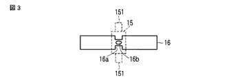
また、ばね部材16は、例えば図3に示すように保持部材15との当接部位に切欠き部16aや開口16bを設けることにより、保持部材とのインサート成形時における堅牢化の促進を図ることができる。
Further, for example, as shown in FIG. 3, the
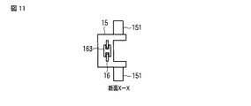
上記保持部材15には、圧電素子10の縦振動の節に対応する両側部に、例えば円柱状の突起部151がそれぞれ突設され、この突起部151は、上記筐体13に設けられた案内溝部131に収容される。これにより、圧電素子10は、保持部材15の突起部151を介して矢印X方向及びZ軸回りの回転方向の位置が規制されて配置される。同時に、圧電素子10は、保持部材15の突起部151と、案内溝部131を設けた筐体13との間が近接されていることで、X軸及びY軸回りの位置が規制される。
The
また、上記圧電素子10には、その上面側にフレキシブルケーブル18が例えば導電性接着材を用いて固着され、このフレキシブルケーブル18を介して図示しない駆動回路と配線接続されている。そして、圧電素子10は、上記駆動回路(図示せず)を介して電圧が印加され、これに応動して縦振動及び屈曲振動を励起し、楕円振動を発生させ、駆動力を得て摩擦接触子11を介して駆動力を被駆動体12に伝達する。
Further, a
上記構成により、モータ組立てを行う場合、例えば摩擦駆動子11の固着された圧電素子10の縦振動の節に対応する位置に、ばね部材16を一体成形した保持部材15が、接着剤を用いて固着される。そして、この圧電素子10は、その摩擦駆動子11が筐体13上に転動部材14を介在して移動自在に配置した被駆動体12上に載置される。この状態で、保持部材15は、その突起部151が、筐体13の案内溝部131に収容されると共に、一体成形したばね部材16の両端部に螺子部材17が配置されて圧電素子10に付与する押圧力の調整が行われる。
With the above configuration, when the motor is assembled, for example, the
そして、圧電素子10は、その上面に配置したフレキシブルケーブル18が上記駆動回路(図示せず)に配線接続され、この駆動回路(図示せず)を介して電圧が印加されると、楕円振動が発生され、これを駆動力として摩擦駆動子11を介して被駆動体12を筐体13に対して矢印X方向に駆動する。
When the
このように、上記超音波モータは、保持部材15にばね部材16を一体成形して、この保持部材15を圧電素子10の縦振動の節に固着配置し、このばね部材16の両端部に、圧電素子10の摩擦駆動子11に付与する押圧力を設定する螺子部材17を、調整自在に配置して構成した。
Thus, in the ultrasonic motor, the
これによれば、圧電素子10は、保持部材15が取付けられると、該保持部材15に一体成形されたばね部材16が所望のばね性を持たせて筐体13内に組付け配置されることにより、組立時におけるばね部材16の保持部材15に対する初期ばね力設定を伴う組付け作業が無くなるために、モータ組立作業の簡略化を図ることが可能となる。
According to this, when the
また、この発明は、上記実施の形態に限ることなく、その他、例えば図4乃至図17に示すように構成してもよく、同様の効果が期待される。但し、この図4乃至図17に示す各実施の形態においては、上記図1乃至図3に示す実施の形態と同一部分について同一符号を付して、その詳細な説明を省略する。 Further, the present invention is not limited to the above embodiment, and may be configured as shown in FIGS. 4 to 17, for example, and the same effect is expected. However, in each embodiment shown in FIGS. 4 to 17, the same parts as those in the embodiment shown in FIGS. 1 to 3 are denoted by the same reference numerals, and detailed description thereof is omitted.
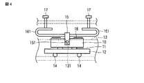
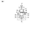
図4及び図5に示す実施の形態では、上記ばね部材16の両端部に、例えば湾曲した屈曲部161を設けて、この屈曲部161の開放端側に対して筐体13に螺合調整自在に設けた螺子部材17を当接させて配置し、この螺子部材17の螺合調整により、先端部で湾曲部161を押圧するように構成した。
In the embodiment shown in FIGS. 4 and 5, for example,
これによれば、ばね部材16の変形部の長さを長く採ることが可能となり、ばね定数を小さく設定することができるため、上記ばね部材16による押圧力の高精度な調整を実現することが可能となる。
According to this, since the length of the deformed portion of the
また、図6に示す実施の形態では、上記ばね部材16の両端部に段状に屈曲させた屈曲部162を設けて、この屈曲部162に対して螺子部材17を、押圧力調整用コイルばね19を挟んで遊挿配置させ、この螺子部材17の先端部を上記筐体13に螺合調整自在に螺合させて配置するように構成した。これによれば、ばね定数を小さくすることが可能となり、コイルばね19の作用により、さらに高精度な押圧力調整を実現することが可能となる。
Further, in the embodiment shown in FIG. 6, a
そして、これによれば、例えば筐体蓋を設けたりすることなく螺子部材17の配置が可能となるうえ、該螺子部材17の配置を含めた高さ寸法を小さく設定することが可能となり、小形化の促進を図ることができる。
According to this, for example, the
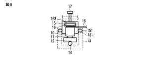
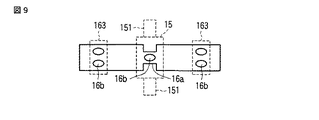
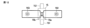
また、図7乃至図9に示す実施の形態では、ばね部材16の両端部に鉢巻に外周部を覆うように例えば樹脂材料製の弾性部163を、上記螺子部材17の先端部に対応して一体成形して、この弾性部163に螺子部材17の先端を係合させてばね部材16の押圧力を調整するように構成した。これによれば、ばね部材16は、その弾性部163の弾性力により、螺子部材17との当接による発生する衝突振動を吸収することができるため、より高精度な駆動特性を得ることが可能となる。
Further, in the embodiment shown in FIGS. 7 to 9, for example, an
そして、この実施の形態においても、例えば図9に示すようにばね部材16の保持部材15との当接部位に切欠き部16aや開口16bを設けると共に、弾性部163との当接部位に、例えば開口16bを設けて保持部材15とインサート成形することで、堅牢に一体成形することが可能となる。
Also in this embodiment, for example, as shown in FIG. 9, a
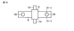
なお、上記弾性部163としては、その他、図10乃至図12に示すようにばね部材16の両端部における中間位置に上記螺子部材17の先端部に対向させて、例えば島の如き円形状に形成するようにしてもよい。
In addition, the
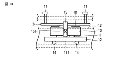
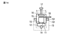
また、図13及び図14に示す実施の形態では、保持部材15にばね部材16をインサート成形により一体成形すると共に、該保持部材15を、圧電素子10の縦振動の節に対応する位置にインサート成形により一体成形するように構成した。これによれば、保持部材15の圧電素子10への組付け作業が削減されることにより、さらに組立作業性の向上を図ることが可能となる。
なお、この実施の形態においても、上述した図4乃至図12に示す構成を適用することが可能である。
In the embodiment shown in FIGS. 13 and 14, the
Also in this embodiment, the configuration shown in FIGS. 4 to 12 described above can be applied.
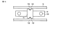
さらに、図15に示す実施の形態では、例えば圧電素子10を筐体13内に位置決め配置する手段として、保持部材15に一対の位置決め用凹部152を、圧電素子10を挟んで両側部に設け、筐体13に位置決め用突起部132を設けて相互を係合させて圧電素子10を位置決め配置するように構成した。
Further, in the embodiment shown in FIG. 15, for example, as a means for positioning and arranging the
また、図16は、例えば位置決め手段として、ばね部材16に一対の突起部164を、圧電素子10の長手方向であって、保持部材15を挟んだ両端部に2組設けて、この2組の位置決め用突起部164をそれぞれ筐体13に設けた位置決め用凹部133に係合させて圧電素子10を位置決め配置するように構成した。
16 shows, for example, as a positioning means, two pairs of
そして、この図15及び図16に示す各実施の形態において、ばね部材16の両端部に弾性部163を一体形成することにより、さらに良好な効果が期待される。また、この各実施の形態においても、ばね部材16に上記図4及び図5の実施の形態と同様の屈曲部161を設けて構成したり、あるいは図6に示す実施の形態と同様の屈曲部162を設けて構成することも可能である。
Further, in each of the embodiments shown in FIGS. 15 and 16, by forming the
よって、この発明は、上記実施の形態に限ることなく、その他、実施段階ではその要旨を逸脱しない範囲で種々の変形を実施し得ることが可能である。さらに、上記実施の形態には、種々の段階の発明が含まれており、開示される複数の構成要件における適宜な組合せにより種々の発明が抽出され得る。 Therefore, the present invention is not limited to the above-described embodiment, and various modifications can be made without departing from the scope of the invention at the stage of implementation. Further, the above embodiments include inventions at various stages, and various inventions can be extracted by appropriately combining a plurality of disclosed constituent elements.
例えば実施の形態に示される全構成要件から幾つかの構成要件が削除されても、発明が解決しようとする課題の欄で述べた課題が解決でき、発明の効果で述べられている効果が得られる場合には、この構成要件が削除された構成が発明として抽出され得る。 For example, even if some constituent requirements are deleted from all the constituent requirements shown in the embodiment, the problem described in the column of the problem to be solved by the invention can be solved, and the effect described in the effect of the invention can be obtained. In such a case, a configuration in which this configuration requirement is deleted can be extracted as an invention.
10…圧電素子、11…摩擦接触子、12…被駆動体、13…筐体、131…案内溝部、132…位置決め用突起部、133…位置決め用凹部、14…転動部材、15…保持部材、151…突起部、152…位置決め用凹部、16…ばね部材、16a…切欠き部、16b…開口、161,162…屈曲部、163…弾性部、164…位置決め用突起部、17…螺子部材、18…フレキシブルケーブル、19…コイルばね。
DESCRIPTION OF
Claims (8)
圧電素子と、
前記圧電素子に設けられ、前記駆動力を前記被駆動体に伝達する摩擦接触子と、
前記圧電素子に設けられ、筐体に位置決め保持される保持部材と、
前記保持部材に一体成形され、前記圧電素子の摩擦接触子を前記被駆導体に摩擦駆動可能に押圧する押圧部材と、
前記押圧部材に付与する前記被駆動体に対する押圧力を調整する押圧調整機構と、
を具備することを特徴とする超音波モータ。 An ultrasonic motor that excites longitudinal vibration and bending vibration simultaneously to generate elliptical vibration, obtains a driving force by the elliptical vibration, and relatively drives a driven body,
A piezoelectric element;
A friction contact provided on the piezoelectric element for transmitting the driving force to the driven body;
A holding member provided in the piezoelectric element and positioned and held in the housing;
A pressing member that is integrally formed with the holding member and presses the friction contact of the piezoelectric element against the driven conductor so as to be frictionally driven;
A pressing adjustment mechanism for adjusting a pressing force applied to the driven body to be applied to the pressing member;
An ultrasonic motor comprising:
Priority Applications (2)
| Application Number | Priority Date | Filing Date | Title |
|---|---|---|---|
| JP2008313569A JP2010141973A (en) | 2008-12-09 | 2008-12-09 | Ultrasonic motor |
| US12/634,130 US20100141091A1 (en) | 2008-12-09 | 2009-12-09 | Ultrasonic motor |
Applications Claiming Priority (1)
| Application Number | Priority Date | Filing Date | Title |
|---|---|---|---|
| JP2008313569A JP2010141973A (en) | 2008-12-09 | 2008-12-09 | Ultrasonic motor |
Publications (1)
| Publication Number | Publication Date |
|---|---|
| JP2010141973A true JP2010141973A (en) | 2010-06-24 |
Family
ID=42230288
Family Applications (1)
| Application Number | Title | Priority Date | Filing Date |
|---|---|---|---|
| JP2008313569A Pending JP2010141973A (en) | 2008-12-09 | 2008-12-09 | Ultrasonic motor |
Country Status (2)
| Country | Link |
|---|---|
| US (1) | US20100141091A1 (en) |
| JP (1) | JP2010141973A (en) |
Cited By (3)
| Publication number | Priority date | Publication date | Assignee | Title |
|---|---|---|---|---|
| CN104362891A (en) * | 2014-12-09 | 2015-02-18 | 苏州科技学院 | Bi-directional driving linear ultrasonic motor |
| JP2016533159A (en) * | 2013-09-13 | 2016-10-20 | フィジック インストゥルメント(ピーアイ)ゲーエムベーハー アンド ツェーオー.カーゲー | Compact general-purpose stick-slip piezoelectric motor |
| JP2017051040A (en) * | 2015-09-04 | 2017-03-09 | キヤノン株式会社 | Vibration wave motor |
Families Citing this family (10)
| Publication number | Priority date | Publication date | Assignee | Title |
|---|---|---|---|---|
| JP5709413B2 (en) | 2010-06-21 | 2015-04-30 | キヤノン株式会社 | Vibration type driving device |
| JP2012165496A (en) * | 2011-02-03 | 2012-08-30 | Tamron Co Ltd | Vibration motor and lens drive mechanism |
| JP5942403B2 (en) * | 2011-12-06 | 2016-06-29 | セイコーエプソン株式会社 | Piezoelectric motor, drive device, electronic component inspection device, electronic component transport device, printing device, robot hand, and robot |
| JP5773900B2 (en) * | 2012-01-30 | 2015-09-02 | キヤノン株式会社 | motor |
| CN103427705B (en) * | 2013-08-14 | 2015-06-24 | 金陵科技学院 | Bimodal and antifriction drive platy piezoelectric motor with single drive foot and operating mode of motor |
| CN104362897A (en) * | 2014-12-09 | 2015-02-18 | 苏州科技学院 | Single-electric-signal-driven rotary ultrasonic motor |
| JP6570335B2 (en) * | 2015-06-17 | 2019-09-04 | キヤノン株式会社 | Vibration type actuator, lens driving device and ultrasonic motor |
| CN105720858B (en) * | 2016-04-18 | 2017-08-04 | 南京理工大学 | An Impact Piezoelectric Drive Device with Precisely Adjustable Friction Force |
| JP6818428B2 (en) * | 2016-04-28 | 2021-01-20 | キヤノン株式会社 | Vibration wave motor and equipment using it |
| CN106953539B (en) * | 2017-04-14 | 2019-04-12 | 哈尔滨工业大学 | Vertical-curved compound creeping motion type precision piezoelectric actuator and its motivational techniques |
Citations (3)
| Publication number | Priority date | Publication date | Assignee | Title |
|---|---|---|---|---|
| JPH08182359A (en) * | 1994-12-21 | 1996-07-12 | Olympus Optical Co Ltd | Ultrasonic actuator |
| JPH11164573A (en) * | 1997-11-26 | 1999-06-18 | Nikon Corp | Vibration actuator |
| JP3825643B2 (en) * | 2001-02-15 | 2006-09-27 | セイコーインスツル株式会社 | Ultrasonic motor and electronic device with ultrasonic motor |
Family Cites Families (1)
| Publication number | Priority date | Publication date | Assignee | Title |
|---|---|---|---|---|
| JP2008178250A (en) * | 2007-01-19 | 2008-07-31 | Olympus Corp | Pressing mechanism of ultrasonic resonator and ultrasonic motor |
-
2008
- 2008-12-09 JP JP2008313569A patent/JP2010141973A/en active Pending
-
2009
- 2009-12-09 US US12/634,130 patent/US20100141091A1/en not_active Abandoned
Patent Citations (3)
| Publication number | Priority date | Publication date | Assignee | Title |
|---|---|---|---|---|
| JPH08182359A (en) * | 1994-12-21 | 1996-07-12 | Olympus Optical Co Ltd | Ultrasonic actuator |
| JPH11164573A (en) * | 1997-11-26 | 1999-06-18 | Nikon Corp | Vibration actuator |
| JP3825643B2 (en) * | 2001-02-15 | 2006-09-27 | セイコーインスツル株式会社 | Ultrasonic motor and electronic device with ultrasonic motor |
Cited By (3)
| Publication number | Priority date | Publication date | Assignee | Title |
|---|---|---|---|---|
| JP2016533159A (en) * | 2013-09-13 | 2016-10-20 | フィジック インストゥルメント(ピーアイ)ゲーエムベーハー アンド ツェーオー.カーゲー | Compact general-purpose stick-slip piezoelectric motor |
| CN104362891A (en) * | 2014-12-09 | 2015-02-18 | 苏州科技学院 | Bi-directional driving linear ultrasonic motor |
| JP2017051040A (en) * | 2015-09-04 | 2017-03-09 | キヤノン株式会社 | Vibration wave motor |
Also Published As
| Publication number | Publication date |
|---|---|
| US20100141091A1 (en) | 2010-06-10 |
Similar Documents
| Publication | Publication Date | Title |
|---|---|---|
| JP2010141973A (en) | Ultrasonic motor | |
| JP4802313B2 (en) | Holding device for piezoelectric vibrator | |
| JP5683643B2 (en) | Linear ultrasonic motor and optical apparatus having the same | |
| JP2009142014A (en) | Ultrasonic motor | |
| JP2014183724A (en) | Linear ultrasonic motor and optical device employing the same | |
| US11038439B2 (en) | Vibration-wave motor | |
| CN101350572B (en) | Driving device and manufacturing method thereof | |
| US10193473B2 (en) | Actuator | |
| JP5540188B2 (en) | Linear drive | |
| CN112019085B (en) | Vibration wave motor and electronic device | |
| JP6122452B2 (en) | Actuator | |
| JP6257224B2 (en) | Motor and lens device | |
| US20110096423A1 (en) | Piezoelectric actuator, lens barrel and optical device | |
| JP7676188B2 (en) | Vibration actuator, and optical and electronic devices having the same | |
| JP2011061895A (en) | Ultrasonic motor mechanism | |
| JP6708472B2 (en) | Vibration wave motor and optical device equipped with the vibration wave motor | |
| JPWO2010032826A1 (en) | Support device for vibration actuator | |
| JP6393383B2 (en) | Vibration wave motor | |
| JP2007151239A (en) | Driver | |
| JP7751637B2 (en) | Piezoelectric drive device, piezoelectric drive system | |
| JP2009268235A (en) | Linear drive type ultrasonic motor | |
| JP2008253107A (en) | Drive unit | |
| JP2009268209A (en) | Ultrasonic motor | |
| JP6602037B2 (en) | DRIVE DEVICE AND OPTICAL DEVICE HAVING THE SAME | |
| JP2024110109A (en) | Drive device and vibration wave motor unit |
Legal Events
| Date | Code | Title | Description |
|---|---|---|---|
| A621 | Written request for application examination |
Free format text: JAPANESE INTERMEDIATE CODE: A621 Effective date: 20111014 |
|
| A521 | Request for written amendment filed |
Free format text: JAPANESE INTERMEDIATE CODE: A523 Effective date: 20121109 |
|
| A131 | Notification of reasons for refusal |
Free format text: JAPANESE INTERMEDIATE CODE: A131 Effective date: 20130312 |
|
| A02 | Decision of refusal |
Free format text: JAPANESE INTERMEDIATE CODE: A02 Effective date: 20130702 |