CN107947626B - Motor using vibrator and electronic device - Google Patents
Motor using vibrator and electronic device Download PDFInfo
- Publication number
- CN107947626B CN107947626B CN201710942345.2A CN201710942345A CN107947626B CN 107947626 B CN107947626 B CN 107947626B CN 201710942345 A CN201710942345 A CN 201710942345A CN 107947626 B CN107947626 B CN 107947626B
- Authority
- CN
- China
- Prior art keywords
- vibrator
- holding
- pressing
- ultrasonic motor
- unit
- Prior art date
- Legal status (The legal status is an assumption and is not a legal conclusion. Google has not performed a legal analysis and makes no representation as to the accuracy of the status listed.)
- Active
Links
- 238000003825 pressing Methods 0.000 claims abstract description 109
- 230000033001 locomotion Effects 0.000 claims description 26
- 230000003287 optical effect Effects 0.000 claims description 9
- 238000002788 crimping Methods 0.000 claims description 6
- 238000005452 bending Methods 0.000 description 37
- 238000010586 diagram Methods 0.000 description 25
- ORQBXQOJMQIAOY-UHFFFAOYSA-N nobelium Chemical compound [No] ORQBXQOJMQIAOY-UHFFFAOYSA-N 0.000 description 23
- 238000005096 rolling process Methods 0.000 description 16
- 239000000470 constituent Substances 0.000 description 7
- 238000003466 welding Methods 0.000 description 5
- 239000000853 adhesive Substances 0.000 description 4
- 230000001070 adhesive effect Effects 0.000 description 4
- 238000004519 manufacturing process Methods 0.000 description 3
- 230000004048 modification Effects 0.000 description 3
- 238000012986 modification Methods 0.000 description 3
- 230000000694 effects Effects 0.000 description 2
- 230000005489 elastic deformation Effects 0.000 description 2
- 230000002452 interceptive effect Effects 0.000 description 2
- 239000002184 metal Substances 0.000 description 2
- 229910052751 metal Inorganic materials 0.000 description 2
- 238000000465 moulding Methods 0.000 description 2
- 229910000639 Spring steel Inorganic materials 0.000 description 1
- 238000005299 abrasion Methods 0.000 description 1
- 238000009825 accumulation Methods 0.000 description 1
- 230000005540 biological transmission Effects 0.000 description 1
- 230000006835 compression Effects 0.000 description 1
- 238000007906 compression Methods 0.000 description 1
- 238000009434 installation Methods 0.000 description 1
- 238000005304 joining Methods 0.000 description 1
- 239000007769 metal material Substances 0.000 description 1
- 238000000034 method Methods 0.000 description 1
- 230000002093 peripheral effect Effects 0.000 description 1
- 239000000758 substrate Substances 0.000 description 1
- 230000001629 suppression Effects 0.000 description 1
Images


Classifications
-
- H—ELECTRICITY
- H02—GENERATION; CONVERSION OR DISTRIBUTION OF ELECTRIC POWER
- H02N—ELECTRIC MACHINES NOT OTHERWISE PROVIDED FOR
- H02N2/00—Electric machines in general using piezoelectric effect, electrostriction or magnetostriction
- H02N2/02—Electric machines in general using piezoelectric effect, electrostriction or magnetostriction producing linear motion, e.g. actuators; Linear positioners ; Linear motors
- H02N2/026—Electric machines in general using piezoelectric effect, electrostriction or magnetostriction producing linear motion, e.g. actuators; Linear positioners ; Linear motors by pressing one or more vibrators against the driven body
-
- H—ELECTRICITY
- H02—GENERATION; CONVERSION OR DISTRIBUTION OF ELECTRIC POWER
- H02N—ELECTRIC MACHINES NOT OTHERWISE PROVIDED FOR
- H02N2/00—Electric machines in general using piezoelectric effect, electrostriction or magnetostriction
- H02N2/0005—Electric machines in general using piezoelectric effect, electrostriction or magnetostriction producing non-specific motion; Details common to machines covered by H02N2/02 - H02N2/16
- H02N2/005—Mechanical details, e.g. housings
-
- G—PHYSICS
- G02—OPTICS
- G02B—OPTICAL ELEMENTS, SYSTEMS OR APPARATUS
- G02B7/00—Mountings, adjusting means, or light-tight connections, for optical elements
- G02B7/02—Mountings, adjusting means, or light-tight connections, for optical elements for lenses
- G02B7/04—Mountings, adjusting means, or light-tight connections, for optical elements for lenses with mechanism for focusing or varying magnification
- G02B7/10—Mountings, adjusting means, or light-tight connections, for optical elements for lenses with mechanism for focusing or varying magnification by relative axial movement of several lenses, e.g. of varifocal objective lens
-
- H—ELECTRICITY
- H02—GENERATION; CONVERSION OR DISTRIBUTION OF ELECTRIC POWER
- H02N—ELECTRIC MACHINES NOT OTHERWISE PROVIDED FOR
- H02N2/00—Electric machines in general using piezoelectric effect, electrostriction or magnetostriction
- H02N2/0005—Electric machines in general using piezoelectric effect, electrostriction or magnetostriction producing non-specific motion; Details common to machines covered by H02N2/02 - H02N2/16
- H02N2/001—Driving devices, e.g. vibrators
- H02N2/0015—Driving devices, e.g. vibrators using only bending modes
-
- H—ELECTRICITY
- H02—GENERATION; CONVERSION OR DISTRIBUTION OF ELECTRIC POWER
- H02N—ELECTRIC MACHINES NOT OTHERWISE PROVIDED FOR
- H02N2/00—Electric machines in general using piezoelectric effect, electrostriction or magnetostriction
- H02N2/0005—Electric machines in general using piezoelectric effect, electrostriction or magnetostriction producing non-specific motion; Details common to machines covered by H02N2/02 - H02N2/16
- H02N2/005—Mechanical details, e.g. housings
- H02N2/0055—Supports for driving or driven bodies; Means for pressing driving body against driven body
- H02N2/006—Elastic elements, e.g. springs
-
- H—ELECTRICITY
- H02—GENERATION; CONVERSION OR DISTRIBUTION OF ELECTRIC POWER
- H02N—ELECTRIC MACHINES NOT OTHERWISE PROVIDED FOR
- H02N2/00—Electric machines in general using piezoelectric effect, electrostriction or magnetostriction
- H02N2/02—Electric machines in general using piezoelectric effect, electrostriction or magnetostriction producing linear motion, e.g. actuators; Linear positioners ; Linear motors
- H02N2/04—Constructional details
Landscapes
- Physics & Mathematics (AREA)
- General Physics & Mathematics (AREA)
- Optics & Photonics (AREA)
- General Electrical Machinery Utilizing Piezoelectricity, Electrostriction Or Magnetostriction (AREA)
Abstract
A motor using a vibrator and an electronic apparatus. The motor can hold the vibrator without increasing the size in the traveling direction (driving direction) and without loosening. The motor includes a vibrator and a holding unit that holds the vibrator, and the vibrator and a sliding member that is in frictional contact with the vibrator are moved relative to each other by vibrating the vibrator. The pressing unit presses the vibrator against the friction member, and the holding spring generates a holding force for causing the holding unit to hold the vibrator. The holding unit is not disposed between the pressing unit and the vibrator. The holding direction of the holding force by the holding spring and the pressing direction of the pressing force by the pressing unit are substantially parallel to each other.
Description
Technical Field
The present invention relates to a motor using a vibrator, and an electronic apparatus using the motor.
Background
Generally, in an ultrasonic motor, a vibrator that periodically vibrates by applying a high-frequency voltage is brought into pressure contact with a slide member, thereby moving the slide member and the vibrator relative to each other.
Examples of such an ultrasonic motor include holding a vibrator in a state of being freely movable in a pressing direction with respect to a frame member, and connecting the vibrator without looseness in a traveling direction (see japanese patent laid-open No. 2015-126692).
In japanese patent laid-open publication No. 2015-126692, a base to which a vibrator is fixed to a holding member in the following manner: such that fixing portions extending from opposite ends of the base portion in the traveling direction are fixed to the holding member, and the holding member is connected to the carrier member via the rolling members and the urging member, thereby connecting the vibrator to the carrier member without looseness. However, this configuration increases the size of the ultrasonic motor in the traveling direction.
Disclosure of Invention
The invention provides a motor capable of holding a vibrator without increasing the size in the traveling direction (driving direction) and loosening, and an electronic apparatus.
In a first aspect of the present invention, there is provided a motor including a vibrator and a holding unit that holds the vibrator and moves the vibrator and a friction member that is in frictional contact with the vibrator relative to each other by vibrating the vibrator, the motor including: a pressing unit configured to press the vibrator against the friction member; and a holding force generating unit configured to generate a holding force for causing the holding unit to hold the vibrator, wherein the holding unit is not arranged between the pressing unit and the vibrator, and a holding direction of the holding force generated by the holding force generating unit and a pressing direction of the pressing force generated by the pressing unit are substantially parallel to each other.
In a second aspect of the present invention, there is provided an electronic apparatus comprising: a motor including a vibrator and a holding unit that holds the vibrator, moves the vibrator and a friction member that is in frictional contact with the vibrator relative to each other by vibrating the vibrator, and a driving member that drives the driving member by driving the motor, wherein the motor includes: a pressing unit configured to press the vibrator against the friction member; and a holding force generating unit configured to generate a holding force for causing the holding unit to hold the vibrator, wherein the holding unit is not arranged between the pressing unit and the vibrator, and a holding direction of the holding force generated by the holding force generating unit and a pressing direction of the pressing force generated by the pressing unit are substantially parallel to each other.
According to the present invention, the motor can hold the vibrator without increasing the size in the traveling direction (driving direction) thereof and without looseness.
Other features of the present invention will become apparent from the following description of exemplary embodiments (with reference to the accompanying drawings).
Drawings
Fig. 1A and 1B are diagrams for explaining the operation principle of the vibrator as a driving source in the present invention.
Fig. 2A to 2D are diagrams for explaining vibration modes of the vibrator shown in fig. 1A and 1B.
Fig. 3A to 3D are diagrams for explaining the ultrasonic motor.
Fig. 4A to 4D are diagrams for explaining operations performed when the size of the ultrasonic motor is changed.
Fig. 5A and 5B are diagrams for explaining advantageous effects obtained by the ultrasonic motor.
Fig. 6 is a diagram for explaining a lens barrel as an example of an electronic apparatus in which an ultrasonic motor is assembled.
Fig. 7 is a sectional view of a main portion of an ultrasonic motor as a motor according to a second embodiment of the present invention in a driving direction.
Fig. 8A and 8B are views for explaining an ultrasonic motor as a motor according to a third embodiment of the present invention.
Fig. 9A to 9D are diagrams for explaining how the vibrator is held in the ultrasonic motor shown in fig. 8A and 8B.
Fig. 10A to 10D are views for explaining a top plate and a guide member used in the ultrasonic motor shown in fig. 8A and 8B.
Fig. 11 is a diagram for explaining a lens barrel as an example of an electronic apparatus in which the ultrasonic motor shown in fig. 8A and 8B is assembled.
Fig. 12A and 12B are diagrams for explaining the structure of a conventional ultrasonic motor.
Fig. 13A to 13D are diagrams for explaining how a vibrator is held in an ultrasonic motor as a motor according to a fourth embodiment of the present invention.
Fig. 14A to 14D are diagrams for explaining how a vibrator is held in an ultrasonic motor as a motor according to a fifth embodiment of the present invention.
Fig. 15A to 15C are diagrams for explaining how a vibrator is held in an ultrasonic motor as a motor according to a sixth embodiment of the present invention.
Detailed Description
The present invention will be described in detail below with reference to the accompanying drawings showing embodiments of the invention.
Fig. 1A and 1B are diagrams for explaining the operation principle of the vibrator as a driving source in the present invention. Fig. 1A is a perspective view illustrating a vibrator and a sliding member, and fig. 1B is a side view of fig. 1A. Note that the vibrator having the illustrated structure is used in the third embodiment of the present invention described below.
As shown in fig. 1A and 1B, a sliding member denoted by reference numeral 104 as a driven member is in frictional contact with a vibrator denoted by reference numeral 100. The vibrator 100 includes a piezoelectric element 102 and a vibration plate 101, and a high-frequency driving voltage is applied to the piezoelectric element 102. When a high-frequency drive voltage is applied to the piezoelectric element 102, ultrasonic vibration (high-frequency vibration) is generated in the vibrating plate 101. The piezoelectric element 102 and the vibration plate 101 are bonded to each other with an adhesive, for example.
The vibration plate 101 has a rectangular portion 101A (flat surface) of a rectangular shape, the rectangular portion 101A defining a surface to be bonded with the piezoelectric element 102. Further, a surface (one surface) of the vibration plate 101 opposite to the bonding surface is formed with two protrusions 101a (also referred to as a crimping portion or a contact portion) having a predetermined gap. In this example, a two-phase high-frequency voltage is applied to the piezoelectric element 102 to excite ultrasonic vibration in the vibrator 100.
The vibrator 100 combines two-phase ultrasonic vibrations and is in pressure contact with the sliding member 104, so that a driving force is generated in the vibrator 100 by a frictional force generated between the vibrator 100 and the sliding member 104. Then, the generated driving force is transmitted to the slide member 104. In the illustrated example, the driving force moves the vibrator 100 relative to the slide member 104 in an X direction (strictly speaking, in the X direction or in a-X direction opposite to the X direction) indicated by a double-headed arrow O in fig. 1B.
Fig. 2A to 2D are diagrams for explaining vibration modes of the vibrator shown in fig. 1A and 1B. Fig. 2A and 2B show a mode of the first bending vibration (first bending vibration mode), and fig. 2C and 2D show a mode of the second bending vibration (second bending vibration mode).
In an ultrasonic motor (vibration wave motor) using a vibrator, when a high-frequency driving voltage having a specific frequency is applied to the piezoelectric unit 102, a plurality of desired vibration modes are excited. Then, driving vibration (driving vibration) is generated by superimposing these vibration modes.
In the example shown in fig. 1A and 1B, two bending vibration modes are excited in the vibrator 100. Fig. 2A and 2B show a first bending vibration mode, which is a mode of bending vibration in the lateral direction of the vibrator 100. Fig. 2A shows the movement of the vibrator 100 when viewed from the longitudinal direction (X direction) of the piezoelectric element 102, which is caused when a positive voltage is simultaneously applied to two electrodes of the piezoelectric element 102 that are separated in the X direction as the longitudinal direction of the piezoelectric element 102, and fig. 2B shows the movement of the vibrator 100 when viewed from the longitudinal direction (X direction), which is caused when a negative voltage is simultaneously applied to the two electrodes.
Fig. 2C and 2D show a second bending vibration mode, which is a mode of bending vibration in the longitudinal direction of the vibrator 100. Fig. 2C shows the movement of the vibrator 100 when viewed from the lateral direction (Y direction) of the piezoelectric element 102, which is caused when a positive voltage is applied to both electrodes at the same time, and fig. 2D shows the movement of the vibrator 100 when viewed from the lateral direction (Y direction), which is caused when a negative voltage is applied to both electrodes at the same time. As shown in fig. 2A to 2D, the bending direction in the first bending vibration mode and the bending direction in the second bending vibration mode are orthogonal to each other.
The protrusions 101a are provided at positions each corresponding to an antinode 201 of the first bending vibration or in the vicinity of the antinode 201 of the first bending vibration. The protrusion 101a repeats the movement in accordance with the first bending vibration as shown in fig. 2A and 2B, thereby performing vertical reciprocating movement indicated by arrows P1 and P2 in the Z direction. This reciprocating motion is the pushing (thrast) component of the driving motion. Note that reference numeral 202 denotes a node of the first bending vibration of the vibrator 100.
Further, the protrusions 101a are provided at positions each corresponding to the node 204 of the second bending vibration or in the vicinity of the node 204 of the second bending vibration. The protrusion 101a performs the swing pivoting about the position by repeating the movement in accordance with the second bending vibration as shown in fig. 2C and 2D, thereby performing the reciprocating movement indicated by the double-headed arrow Q in the X direction. The reciprocating motion is the feed component of the drive motion. Note that reference numeral 203 denotes an antinode of the second bending vibration of the vibrator 100.
Here, it is assumed that the direction in which the vibrator 100 is deformed in the pushing motion and the feeding motion is the Z direction. In order to excite the second bending vibration mode in the vibrator 100, the piezoelectric element 102 has two electrodes separated in the X direction as the longitudinal direction.
The two bending vibration modes (i.e., the first bending vibration and the second bending vibration) are excited simultaneously, and the two bending vibrations orthogonal to each other are superimposed. As a result, the vertical movement (indicated by arrow P) and the swing movement (indicated by double-headed arrow Q) are combined, whereby the protrusions 101a each perform an elliptical movement indicated by arrow R on the X-Z plane. By performing the elliptical motion R, the vibrator 100 can move in the X direction with respect to the slide member 104 that is in pressure contact with the vibrator 100.
Fig. 3A to 3D are diagrams for explaining an ultrasonic motor according to a first embodiment. Fig. 3A shows a sectional view of a main portion of the ultrasonic motor in a direction orthogonal to the driving direction. Fig. 3B shows a sectional view of a main portion of the ultrasonic motor in the driving direction (moving direction). Fig. 3C is an exploded perspective view of the vibrator used in the ultrasonic motor as viewed from above in fig. 3A, for explaining how the vibrator is held. Fig. 3D is an exploded perspective view of the vibrator viewed from below in fig. 3A, for explaining how the vibrator is held. Although in the first embodiment, a so-called direct-acting type (linear type) ultrasonic motor is explained as an example, the ultrasonic motor may be a rotary type or any other type.
The illustrated ultrasonic motor denoted by reference numeral 200 includes a vibration plate 101, and the vibration plate 101 is held by a first holding member 103. The piezoelectric element 102 is fixed to the vibration plate 101 with an adhesive, for example. The piezoelectric element 102 is configured to generate resonance in both the longitudinal direction and the transverse direction in the vibration plate 101 when a high-frequency driving voltage is applied. The vibration plate 101 and the piezoelectric element 102 form a vibrator 100, and when a high-frequency driving voltage is applied, the vibrator 100 generates ultrasonic vibration.
As shown by an arrow a in fig. 3B, the tip ends of the pressure-bonding sections 101a formed on the vibration plate 101 each generate an elliptical motion. By changing the frequency or phase of the high-frequency drive voltage applied to the piezoelectric element 102, the rotation direction and the ellipse ratio of the elliptical motion can be changed, thereby generating desired vibration.
The front end of the crimp portion 101a is in frictional contact with the slide member 104, and a driving force for moving the vibrator 100 relative to the slide member 104 is generated by the elliptical motion of the crimp portion 101 a. This enables the vibrator 100 to be driven in the relative movement direction indicated by the arrow B (the direction orthogonal to the paper surface in fig. 3A, i.e., the left-right direction in fig. 3B).
Note that the relative movement direction corresponds to the optical axis direction in the lens barrel in which the ultrasonic motor is assembled. In addition, the slide member 104 is fixed to a unit support member 116 described below by a fastener such as a screw.
The vibration plate 101 has a protrusion 101b on the surface thereof on which the pressure contact portion 101a is formed, and the height of the protrusion 101b is smaller than the height of the pressure contact portion 101 a. The protrusion 101b and the V-shaped groove 103a formed in the first holding member 103 are fitted (engaged) with each other, thereby connecting the vibration plate 101 to the first holding member 103.
In the connection (e.g., engagement) between the protrusion 101b and the V-groove 103a, the contact portion between the protrusion 101b and the V-groove 103a is located between the piezoelectric element 102 and the slide member 104. This enables effective use of the lower space as shown in fig. 3A.
On the other hand, the first holding member 103 is formed with spring hook portions 103b at opposite ends in the direction orthogonal to the driving direction of the ultrasonic motor, and one end of a holding spring 117 as a holding force generating unit is hooked on the spring hook portions 103 b. The other end of the holding spring 117 is hooked on an associated one of the spring hook portions 105a formed on the second holding member 105. This configuration generates a holding force for holding the vibrator 100 having the vibration plate 101 in the holding direction D via the first holding member 103.
On the other hand, a pressing force in a pressing direction C described below is applied to the vibrator 100. The holding direction D and the pressing direction C are substantially parallel to and opposite to each other, and the pressing force is set to be larger than the holding force. As a result, the pressurizing force receives a reaction force of the holding force, thereby holding the vibrator 100. This allows the first holding member 103 and the vibrator 100 to be connected without looseness in the driving direction B via the protrusion 101B and the V-shaped groove 103 a.
Note that the pressing unit (pressing mechanism) 120 is configured to generate a pressing force larger than the holding force as a pressing force necessary for the pressing contact between the vibrator 100 and the slide member 104. This makes it possible to ensure the necessary holding force and pressing force applied to the crimping portion even after the holding force in the direction indicated by the arrow D is subtracted from the pressing force in the direction indicated by the arrow C.
The pressing plate 108 flexibly presses and holds the piezoelectric element 102 via an elastic member 109. The pressurizing spring 110 is assembled between the spring holding member 111 and the spring base plate 112, thereby forming the pressurizing unit 120. Further, the pressing spring 110 generates a pressing force in the pressing direction C. For this reason, the large diameter portion 111a formed at one end of the spring holding member 111 is loosely fitted into the fitting portion 112a assembled to the spring substrate 112. As a result, after assembly, the pressurizing unit 120 can be maintained in a predetermined state against the spring force of the pressurizing spring 110. As described above, the first holding member 103 is not arranged between the pressing unit 120 and the vibrator 100 in the pressing direction.
The outer diameter portion of the spring base plate 112 is formed with bayonet projections 112b at a plurality of positions in the circumferential direction. In the assembled state of the ultrasonic motor 200, the position of the bayonet projection 112b in the pressing direction C is defined by the bayonet engagement portion 105C formed on the second holding member 105. At this time, the pressing portion 111b formed at the other end of the spring holding member 111 generates a pressing force for pressing the vibrator 100 against the slide member 104 via the pressing plate 108 and the elastic member 109 using the urging force of the pressing spring 110. Thus, the vibrator 100 and the sliding member 104 are in frictional contact with each other.
The moving plate 113, which is a component of the guide portion 107A, is fixed to the contact portion 105b of the second holding member 105 by adhesion or screwing. The moving plate 113 is formed with a plurality of grooves 113a each having a V-shaped cross section for guiding the second holding member 105 in the optical axis direction, and the balls 114 are fitted into the grooves 113 a. The cover plate 115 is fixed to the unit supporting member 116 with screws.
The cover plate 115 is also a component part of the guide portion 107A, and the cover plate 115 is formed with grooves 115a each having a V-shaped cross section at respective positions opposite to the grooves 113a formed in the moving plate 113. Further, the ball 114 is sandwiched by the groove 113a and the groove 115 a. This makes it possible to support the second holding member 105 in such a manner as to move forward or backward in the moving direction (the direction perpendicular to the paper surface in fig. 3A, i.e., the left-right direction in fig. 3B).
Fig. 4A to 4D are diagrams for explaining operations performed when the size of the ultrasonic motor shown in fig. 3A to 3D is changed. Fig. 4A shows a normal state of the slide member when viewed from the same direction as in fig. 3A, and fig. 4B shows a state in which the installation height of the slide member is changed. Fig. 4C shows a normal state of the slide member when viewed from the same direction as in fig. 3B, and fig. 4D shows an inclined state of the slide member.
An operation of the ultrasonic motor shown in fig. 3A to 3D to stably maintain the frictional contact between the vibrator 100 and the sliding member 104 by absorbing the influence caused by the variation in the sizes of the constituent parts will now be described with reference to fig. 4A to 4D.
In the ultrasonic motor 200 shown in fig. 3A to 3D, the heights of the vibrator 100 and the slide member 104 in the pressing direction C may vary due to manufacturing variations of mechanical parts. Therefore, it is necessary to prevent the frictional contact state from being affected by the height variation in order to stabilize the transmission of the driving force.
Fig. 4A shows a normal state of the ultrasonic motor 200 in which the slide member 104 is at the center of the design height in the pressing direction C. Further, fig. 4B illustrates a state of the ultrasonic motor 200 in which the mounting height of the slide member 104 is moved upward in an exaggerated manner.
Referring to fig. 4A, the pressing unit 120 extends with the moving plate 113 and the second holding member 105 as one end, thereby pressing the vibrator 100 against the sliding member 104 in a state where the plurality of members are held between the one end and the vibrator 100. Further, the holding spring 117 pulls the first holding member 103 toward the second holding member 105, thereby generating a holding force.
Referring now to fig. 4B, assume that the mounting height of the slide member 104 is moved upward by the height indicated by arrow E. The change in height indicated by the arrow E is absorbed by the elastic deformation of the holding spring 117, and the first holding member 103 is pulled upward by the height indicated by the arrow F while maintaining the holding force. The height variation indicated by the arrow E is small, and therefore the variation in the holding force generated by the elastic deformation of the holding spring 117 is sufficiently small relative to the original holding force. Therefore, it is possible to absorb the height change of the slide member 104 while maintaining the necessary holding force.
Next, a case where the slide member 104 is inclined will be described with reference to fig. 4C and 4D.
Fig. 4C shows a normal state of the slide member 104. The mechanism for generating the holding force is as described above with reference to fig. 4A.
Referring to fig. 4D, it is assumed that the slide member 104 is mounted at a position rotated in the counterclockwise direction indicated by the arrow G. In this case, the rotation indicated by the arrow G is absorbed by the rotation of the vibrator 100 about the protrusion 101b in the direction indicated by the arrow G. The vibrator 100 rotates relatively while maintaining the connection of the vibrator 100 by the V-shaped groove 103a formed in the first holding member 103 and the protrusion 101b formed in the vibration plate 101.
Similarly, the pressing plate 108 rotates in the direction indicated by the arrow G around the hemispherical portion 108a formed at the portion in contact with the pressing unit 120. Since the pressurizing unit 120 is in contact with the hemispherical portion 108a of the pressurizing plate 108, the pressurizing unit 120 can maintain the pressurized state even when the pressurizing plate 108 rotates.
As described above, in the ultrasonic motor shown in fig. 3A to 3D, it is possible to absorb the influence caused by the variation in the mounting height of the slide member, thereby stably maintaining the frictional contact between the vibrator 100 and the slide member 104.
Fig. 5A and 5B are diagrams for explaining advantageous effects obtained by the ultrasonic motor shown in fig. 3A to 3D. Fig. 5A is a sectional view taken along a driving direction of the ultrasonic motor corresponding to fig. 3B, and fig. 5B is a sectional view of a conventional ultrasonic motor taken along the driving direction.
In the conventional ultrasonic motor shown in fig. 5B, the vibrator 100 is held by the first holding member 103 in the following manner: a connection portion (protrusion) 101B of the vibration plate 101 extending in the driving direction is fixed to a protrusion 103B formed on the first holding member 103. Further, rolling rollers 118 are provided at opposite ends of the vibration plate 101 in the driving direction, and the vibrator 100 is held by an urging spring 119 without play. Note that the operation and the like of the illustrated conventional ultrasonic motor are known, and therefore, the description thereof is omitted.
In contrast, in the ultrasonic motor shown in fig. 5A, the vibrator 100 is connected to the first holding member 103 at the center in the driving direction of the ultrasonic motor by the protrusion 101b formed on the vibration plate 101 and the V-groove 103a formed on the first holding member 103. Further, the holding spring 117 is disposed in a direction orthogonal to the driving direction. This makes it unnecessary to provide a holding portion (i.e., the above-described connecting portion 101B) extending in the driving direction, thereby enabling the length in the driving direction to be reduced by the length indicated by the arrow H in fig. 5B.
As described above, in the ultrasonic motor shown in fig. 5A, the dimension in the driving direction (traveling direction) can be reduced and connection without backlash can be performed.
Fig. 6 is a diagram for explaining a lens barrel as an example of an electronic apparatus (lens apparatus) in which the ultrasonic motor 200 shown in fig. 3A to 3D is assembled. Note that in fig. 6, the lens barrel has a substantially rotationally symmetric shape, and therefore only the upper half of the lens barrel is shown.
A lens barrel denoted by reference numeral 302 is detachably attached to a camera body 301, and the camera body 301 is provided with an image pickup device 301 a. The mount 311 of the camera body 301 is provided with a bayonet portion for mounting the lens barrel 302 to the camera body 301.
The focus lens holding frame 316 is linearly movably held by a guide rod 317 held by the front cylinder 313 and the rear cylinder 314. The unit supporting member 116 of the ultrasonic motor 200 is formed with a flange portion (not shown) through which the unit supporting member 116 is fixed to the rear cylinder 314 with screws, for example.
In the ultrasonic motor 200, when the movable unit including the first holding member 103 is driven, the driving force of the ultrasonic motor 200 is transmitted to the focus lens holding frame 316 via the first holding member 103. Then, the focus lens holding frame 316 is guided by the guide rod 317 and linearly moved. Thereby, focus adjustment is performed.
As described above, in the first embodiment of the present invention, the vibrator is connected at the center in the driving direction thereof. Then, a holding force necessary for holding the connection portion is generated in a direction orthogonal to the driving direction. This makes it possible to reduce the size of the vibrator of the ultrasonic motor in the driving direction.
An ultrasonic motor as a motor according to a second embodiment of the present invention will be described below.
Fig. 7 is a sectional view of a main portion of an ultrasonic motor as a motor according to a second embodiment in a driving direction. Note that description of the same configuration as that described in the first embodiment of the ultrasonic motor as the motor according to the second embodiment is omitted, and only different points will be described below.
As described above, the vibrator 100 is connected to the first holding member 103 by engaging the protrusion 101b and the V-groove 103a formed in the first holding member 103 with each other, and the vibrator 100 is held by the holding force in the direction indicated by the arrow D generated by the holding spring 117.
The second embodiment differs from the first embodiment in the configuration for generating the pressurizing force. Referring to fig. 7, the slide member 104 is not fixed to the unit supporting member 116, but one ends of the pressurizing springs 110 are respectively hooked to the spring hook portions 104 a. Further, the other end of the pressurizing spring 110 is hooked on the unit supporting member 116. Thereby, the slide member 104 is pulled up in the direction indicated by the arrow C, thereby generating a pressing force for pressing the vibrator 100.
Further, in fig. 7, the pressing plate 108 is not formed with the hemispherical portion, but the second holding member 105 is formed with the hemispherical portion 105d, thereby absorbing the variation in the mounting height of the slide member 104 in the above-described manner.
In the second embodiment, the direction D in which the holding force is generated and the direction C in which the pressing force is applied are the same direction when viewed from the slide member 104. For this reason, the cancellation of the force described in the first embodiment does not occur. Therefore, it is not necessary to cause the pressurizing spring 110 to generate a pressurizing force large enough with a margin for overcoming the offset to provide the holding force.
As described above, in the second embodiment of the present invention, similarly to the first embodiment, the dimension in the driving direction can be reduced, and further, the pressing force applied by the pressing unit such as the pressing spring can be set without considering the holding force.
An ultrasonic motor as a motor according to a third embodiment of the present invention will be described below.
Fig. 8A and 8B are views for explaining an ultrasonic motor as a motor according to a third embodiment. Fig. 8A shows the ultrasonic motor in a cut-away view as viewed from the side, and fig. 8B is a sectional view of the transducer taken along a-a in fig. 8A. In fig. 8A and 8B, components corresponding to those of the vibrator shown in fig. 1A and 1B and those of the ultrasonic motor as the motor according to the first embodiment shown in fig. 3A to 3D are denoted by the same reference numerals.
The ultrasonic motor shown by reference numeral 151 has the vibrator 100 described with reference to fig. 1A and 1B disposed at the center of the lower portion thereof. As described above, the vibrator 100 as a driving source includes the vibration plate 101 and the piezoelectric element 102, and a high-frequency driving voltage is applied to the piezoelectric element 102. The vibration plate 101 is bonded to the piezoelectric element 102 with, for example, an adhesive, and generates ultrasonic vibration in accordance with a high-frequency driving voltage applied to the piezoelectric element 102.
The vibration plate 101 is formed with two protrusions 101a, and the pressure receiving member 403 is fixed to the upper surface of the piezoelectric element 102 with an adhesive, for example. Further, the pressure receiving member 403 is formed with a hemispherical portion 403a at a central portion thereof in the Z direction. The vibrator 100 is engaged with a thin plate spring 405 formed of spring steel.
Fig. 8B shows a state of the vibrator 100 when viewed from the Z direction. Fig. 8B shows the positions of the antinode 201 and the node 202 corresponding to the first bending vibration, the positions of the antinode 203 and the node 204 corresponding to the second bending vibration, and the positions corresponding to six node intersection points 205 that are the intersection points of the node 202 and the node 204.
Fig. 9A to 9D are diagrams for explaining how the vibrator is held in the ultrasonic motor shown in fig. 8A and 8B. Fig. 9A shows how the vibrator is held in a cut-out view when viewed from the side, fig. 9B shows the vibrator when viewed from the bottom, fig. 9C is a sectional view taken along B-B in fig. 9A showing how the vibrator is held, and fig. 9D is a sectional view showing a modification of how the vibrator is held.
The vibration plate 101 is formed with joint portions 101c at respective positions corresponding to the two node intersections 205 or in the vicinity of the two node intersections 205, the joint portions 101c extending in the-Z direction (the direction opposite to the Z direction) from the surface on which the protrusion portions 101a are formed. Each of the engaging portions 101c is integrally formed with a convex portion 101ca, and a leading end of the convex portion 101ca is formed into a hemispherical shape by press-forming, for example.
The joint receiving portions 121 for receiving the joint portions 101c are fixed to the thin plate spring 405 at respective positions by, for example, welding or bonding, and the respective positions of the joint receiving portions 121 are adjusted by being metered to the same positions of the joint portions 101c in the-Z direction. The engagement receiving portions 121 each have a tapered recess 121a for receiving an associated one of the male portions 101ca in the-Z direction. The position of the concave portion 121a is adjusted by quantifying so that the concave portion 121a is coaxial with the convex portion 101 ca.
Note that in the present embodiment, a two-component part formed of the joint portion 101c and the joint receiving portion 121 joined to each other is referred to as a vibrator joint portion. Further, the joint receiving portion 121 and the thin plate spring 405 are referred to as a vibrator holding member 131, and the joint portion 101c of the vibrator 100 and the vibrator holding member 131 are collectively referred to as a vibrator holding portion.
Further, the thin plate spring 405 is formed with two escape holes 405b, and the two protrusions 101a of the vibrator 100 are fitted into the two escape holes 405b, thereby preventing interference between the thin plate spring 405 and the two protrusions 101a of the vibrator 100. Further, the thin plate spring 405 has screw holes 405c formed at four corners thereof for fixing the thin plate spring 405 to a guide member 107 described later. The thin plate spring 405 is fixed to the guide member 107 with a fixing screw 106. Thereby, the driving force of the vibrator 100 in the X direction is transmitted to the guide member 107.
Note that the vibrator engagement portion formed of the engagement portion 101c and the engagement receiving portion 121 is designed to be housed in a space around the protrusion portion 101a of the vibrator 100.
Referring again to fig. 8A, a pressing mechanism (pressing unit) 416 for pressing the vibrator 100 in the-Z direction is arranged inside the guide member 107. The pressurizing unit 416 includes a pressurizing shaft 411, a pressurizing spring receiving member 412, and a pressurizing spring 413. The outer periphery of the pressurizing spring receiving member 412 has a bayonet shape portion 412 a. The bayonet shape portion 412a is fitted into a bayonet hole shape portion 107b formed on the inner periphery of the central upper portion of the guide member 107 in the Z direction. The pressing shaft 411 is axially movably inserted into a center hole 412c formed in the Z direction of the pressing spring receiving member 412.
The pressing spring 413 has an upper end in the Z direction, which is inserted into a spring receiving groove 412b formed in the pressing spring receiving member 412, and the inserted end is a fixed end. Further, the pressing spring 413 has a portion as a movable end that contacts a spring receiving portion 411a located at an end of the pressing shaft 411 in the-Z direction, and generates a pressing force 413a in the Z direction in a compressed state.
The pressing force 413a generated by the pressing spring 413 presses the spring receiving portion 411a downward in the-Z direction, thereby pressing the hemispherical portion 403a of the pressure receiving member 403 coupled to the vibrator 100. When the hemispherical portion 403a is pressurized, a force in the-Z direction acts on the vibrator 100 to deform the thin plate spring 405 engaged with the vibrator 100 and bring the protrusion 101a into pressurized contact with the slide member 104.
In this state, the dimensional relationship in the pressing direction between the associated component parts is designed to be: so that the thin plate spring 405 holding the vibrator 100 is bent in the-Z direction (the bending of the thin plate spring 405 is not shown in fig. 8A). Thus, a reaction force 405a of the thin plate spring 405 is generated in the Z direction (see fig. 9C). Then, the tapered recess 121a of the engagement receiving portion 121 is held in constant pressing contact with the convex portion 101ca of the engagement portion 101c, thereby preventing the vibrator engagement portion of the vibrator 100 from loosening in the X direction, the Y direction, and the Z direction. This prevents the vibrator joint portion from being loosened in the driving direction (X direction) during driving of the vibrator 100.
Further, due to the spring characteristics of the thin plate spring 405, the thin plate spring 405 has no rigidity (i.e., is easily bent) in the direction (Z direction) orthogonal to the plane thereof, but has rigidity (i.e., prevents generation of looseness) in the direction (X direction) orthogonal to the Z direction. This prevents the vibrator holding portion from being loosened in the driving direction during driving of the vibrator 100. Further, the bending of the thin plate spring 405 in the pressing direction makes it easy to balance the posture of the vibrator 100 with respect to the slide member 104.
Note that in the above example, in order to reduce an error with respect to a design value of the pressing force 413a caused by accumulation of various dimensional manufacturing errors in the pressing direction of the component parts of the vibrator motor in the assembled state, a compression coil spring having a small spring constant is used as the pressing spring 413. On the other hand, in order to miniaturize the size of the ultrasonic motor 151, a plate spring may be used as the pressurizing spring 413 to reduce a space in which component parts are arranged, so that the size of the ultrasonic motor 151 in the pressurizing direction can be reduced.
The unit base 409 serves to support the entire ultrasonic motor 151. The sliding member 104 made of a metal material in frictional contact with the vibrator 100 is fixed to the bottom side of the unit base 409, and the top plate 410 is fixed to the upper side of the unit base 409. Four rolling members 408 are sandwiched between the top plate 410 and the guide member 107. When the rolling member 408 rolls in a state of being sandwiched between the top plate 410 and the guide member 107, the guide member 107 moves in the X direction.
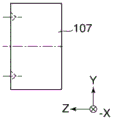
Fig. 10A to 10D are diagrams for explaining a top plate and a guide member used for the ultrasonic motor shown in fig. 8A and 8B. Fig. 10A shows the top panel when viewed from the bottom, and fig. 10B shows the top panel when viewed from the side. Fig. 10C shows the guide member when viewed from above, and fig. 10D shows the guide member when viewed from the side.
The top plate 410 is formed with two V-shaped guide grooves 410a, and the guide member 107 is also formed with two V-shaped guide grooves 107 a. The rolling member 408 is sandwiched between these guide grooves 410a and 107a, and rolls between the grooves.
The guide member 107 is formed with a bayonet hole-shaped portion 107b for fitting with the pressurizing unit 416. Further, the top plate 410 is formed with a square hole 410c for fixing/removing the pressurizing unit 416 and a screw hole 410b for fixing the top plate 410 to the unit base 409.
As described above, in the ultrasonic motor 151 shown in fig. 8A and 8B, the pressing unit 416 presses the vibrator 100 against the slide member 104, and the protrusion 101a comes into frictional contact with the slide member 104. Then, when a high-frequency driving voltage is applied to the piezoelectric element 102 to excite ultrasonic vibration in the vibrator 100, a driving force is generated by a frictional force generated between the protrusion 101a and the sliding member 104. As a result, the vibrator 100 moves in the X direction (strictly speaking, in the X direction or in the-X direction opposite to the X direction) indicated by the double-headed arrow O in fig. 8A with respect to the slide member 104.
Since the convex portion 101ca of the engaging portion 101c and the tapered concave portion 121a of the engagement receiving portion 121 engage with each other, the driving force is transmitted to the thin plate spring 405 and further to the guide member 107 according to the movement of the vibrator 100 in the X direction. Then, the rolling of the rolling member 408 causes the guide member 107 to move in the X direction.
As described above, fig. 9D shows a variation of the vibrator joint portion. Fig. 9D shows the vibrator joint portion at the same cross-sectional position as shown in fig. 9C, that is, at the same position and in the same direction as in fig. 9C.
In fig. 9D, the transducer 100 has joint portions 101D, each joint portion 101D having a front end shaft 101da at its front end, the front end shafts 101da being formed at respective positions corresponding to the two node intersection points 205 or in the vicinity of the two node intersection points 205. The joint portion 101d is formed integrally with the vibration plate 101 by press molding, for example.
The thin plate spring 405 has engagement receiving portions 122, each of which 122 is formed with a hole-shaped portion 122a at the center thereof. The front end shafts 101da are respectively fitted into the hole-shaped portions 122a, thereby preventing looseness of the vibrator engagement portions in the X direction and the Y direction.
As described above, the joint portion formed integrally with the vibration plate 101 can be formed to have various shapes and can function as a part of the vibrator holding portion. Although an example in which the vibrator 100 moves and the slide member 104 is fixed has been described, the vibrator 100 may be fixed and the slide member 104 may move.
Fig. 11 is a diagram for explaining a lens barrel as an example of an electronic apparatus (lens apparatus) having the ultrasonic motor shown in fig. 8A and 8B.
An image pickup optical system denoted by reference numeral 141 provided in the lens barrel includes a first group lens L1 and a second group lens L2 arranged in order from the object side, and a barrel 142 having lenses L1, L2. The focus lens L3 is disposed at a position behind the second group lens L2 and held by the lens holding frame 144. Further, a fourth group lens L4 and a fifth group lens L5 are arranged at respective positions behind the focus lens L3 and held by the barrel 145.
Two main guide rods 146 are used to move the lens holding frame 144 along the optical axis 149, and the two main guide rods 146 are fixed to the inner wall of the lens barrel 141 in such a manner as to extend parallel to the optical axis 149. The ultrasonic motor 151 is disposed inside the lens barrel 141, and in the present example, the unit base 409 is fixed to the inner wall of the lens barrel 141 in such a manner that the guide member 107 is movable in the direction of the optical axis 149.
By connecting the guide member 107 to the lens holding frame 144 using the connecting member 147, the driving force of the vibrator 100 is transmitted to the lens holding frame 144, and the focus lens L3 is moved along the optical axis 149.
Here, a vibrator holding portion of an ultrasonic motor, which holds a vibrator so as to avoid suppressing vibration of the vibrator as much as possible and can be reduced in size, will be described.
Fig. 12A and 12B are diagrams for explaining an example of a conventional ultrasonic motor. Fig. 12A shows a conventional ultrasonic motor in a cut-away view as viewed from the side, and fig. 12B is a sectional view taken along C-C in fig. 12A, showing a vibrator holding portion.
The ultrasonic motor shown in fig. 12A and denoted by reference numeral 152 is different from the ultrasonic motor 151 shown in fig. 8A in the vibrator holding portion, and other constituent components are configured to be the same as those of the ultrasonic motor shown in fig. 8A, and thus description thereof is omitted.
Referring to fig. 12A and 12B, the vibrator 100 has vibrator holding portions at opposite ends in the longitudinal direction, and the joining member 231 is fixed to each vibrator holding portion. First, the left vibrator holding portion shown in fig. 12A and 12B will be explained.
As a measure against the abrasion, the roller receiving portion 135 made of metal is fixed to the engaging member 231. Similarly, a roller receiving portion 132 made of metal is fixed to the guide member 107. Further, a rolling roller member 133 is sandwiched between the two roller receiving portions 132.
The vibrator holding portion on the right side as shown in fig. 12A and 12B will be described.
The roller receiving portion 132 is fixed to the guide member 107, similarly to the vibrator holding portion on the left side. A pressing plate spring 134 for pressing the rolling roller member 133 is arranged at the engaging member 231. Further, the rolling roller member 133 is sandwiched between the roller receiving portion 132 and the pressing leaf spring 134.
In the vibrator holding portion shown in fig. 12A and 12B, the guide member 107 enters between two engaging members 231 provided at opposite ends in the longitudinal direction of the vibrator 100. Further, two rolling roller members 133 are arranged between the two roller receiving portions 132 mounted to the guide member 107 and the roller receiving portion 135 and the pressing leaf spring 134 mounted to the engaging member 231, whereby the pressing leaf spring 134 generates a pressing force 134a in the driving direction (X direction). That is, the pressing force 134a applied by the pressing plate spring 134 prevents the vibrator 100 and the guide member 107 from loosening in the driving direction (X direction).
As a result, in the ultrasonic motor 152 shown in fig. 12A and 12B, the driving (control) position of the vibrator 100 in the X direction (the direction indicated by the arrow O) is directly transmitted to the guide member 107, which improves the driving controllability of the ultrasonic motor 152.
Incidentally, in the vibrator holding portion shown in fig. 12A and 12B, dimensional errors may occur in the pressing direction (Z direction) due to manufacturing tolerances of the slide member 104, the vibrator 100, the guide member 107, the rolling member 408, the top plate 410, and the unit base 409. Further, the change in the posture of the vibrator 100 during the driving thereof changes the positional relationship between the vibrator 100 and the rolling member 408 in the pressing direction (Z direction). This causes loosening of the rolling members 408 between the guide member 107 and the top plate 410 in the pressing direction (Z direction). Further, this can create a situation where the rolling member 408 is tightly sandwiched between the guide member 107 and the top plate 410 in the pressing direction (Z direction).
For this reason, in the vibrator holding portion shown in fig. 12A and 12B, it is necessary to absorb a dimensional error (change in positional relationship) in the pressing direction (Z direction). In the illustrated example, two rolling roller members 133 are arranged in the Z direction between two roller receiving portions 132 mounted to the guide member 107 and a roller receiving portion 135, a pressing leaf spring 134 mounted to the engaging member 231, thereby absorbing dimensional errors (variations) in the pressing direction (Z direction).
This is a function of the vibrator holding portion shown in fig. 12A and 12B to balance the vibrator 100 in the pressing direction (Z direction). That is, the vibrator holding portion shown in fig. 12A and 12B connects the vibrator 100 and the guide member 107, and has a function of eliminating the looseness of the vibrator 100 in the driving direction (X direction) and balancing the vibrator 100 in the pressing direction (Z direction).
However, in the ultrasonic motor 152 shown in fig. 12A and 12B, the vibrator holding portions are arranged at opposite ends of the vibrator 100. This requires an arrangement space for arranging the transducer holding portion in the X direction, and increases the dimension W of the ultrasonic motor 152 in the X direction, resulting in an increase in the dimension of the ultrasonic motor 152. Even if the transducer holding portion is arranged above the transducer 100 in the Z direction, an arrangement space in the Z direction is required, which increases the dimension H of the ultrasonic motor 152 in the Z direction, resulting in an increase in the dimension of the ultrasonic motor 152.
In contrast, in the ultrasonic motor 151 shown in fig. 8A and 8B, the vibrator holding portion other than the portion for fixing the thin plate spring 405 to the guide member 107 is housed in a dead space around the protrusion 101a without interfering with other component parts. This makes it possible to reduce the outer dimensions W and H of the ultrasonic motor 151, thereby reducing the size of the ultrasonic motor 151.
Further, in the ultrasonic motor 151 shown in fig. 8A and 8B, the transducer holding portion is configured such that: the transducer holding portion corresponds to two node intersections 205 which are intersections of the nodes 202 of the first bending vibration and the nodes 204 of the second bending vibration of the transducer 100. By holding the vibrator 100 at a position having the minimum vibration width of the vibrator 100 in this way, the vibrator 100 can be held so as to avoid suppressing the vibration of the vibrator 100 as much as possible.
As described above, in the third embodiment of the present invention, the vibrator can be held so as to avoid suppressing the vibration of the vibrator 100 as much as possible, and the size of the ultrasonic motor can also be reduced.
An ultrasonic motor according to a fourth embodiment of the present invention will be described below. The same constituent elements of the fourth embodiment as those of the third embodiment are denoted by the same reference numerals.
The ultrasonic motor according to the fourth embodiment is different from the ultrasonic motor according to the third embodiment in a vibrator holding portion, and other constituent components are configured similarly to those of the ultrasonic motor according to the third embodiment.
Fig. 13A to 13D are diagrams for explaining how the vibrator is held in the ultrasonic motor according to the fourth embodiment. Fig. 13A shows how the vibrator is held in a cut-out view when viewed from the side, fig. 13B shows the vibrator when viewed from the bottom, fig. 13C is a sectional view taken along D-D in fig. 13A showing how the vibrator is held, and fig. 13D is a sectional view showing a modification of how the vibrator is held.
The vibration plate 101 is formed with hole-shaped joints (concave-shaped portions) 101e each having a central axis in the Z direction at respective positions corresponding to the two node intersections 205 or in the vicinity of the two node intersections 205. The joint portion 101e is formed integrally with the vibration plate 101 by press-forming the vibration plate 101, for example, by blanking (blanking). The joint receiving portions 123 for respectively receiving the joint portions 101e are fixed to the thin plate spring 405 at respective positions adjusted by being metered to the same positions in the-Z direction as the joint portions 101e, for example, by welding or bonding. The engagement receiving portions 123 are each formed at a front end thereof with a hemispherical portion 123a for receiving an associated one of the engagement portions 101e in the-Z direction, and the positions of the engagement receiving portion 123 and the engagement portion 101e are adjusted such that the engagement receiving portion 123 is coaxial with the engagement portion 101 e.
Note that, in the present embodiment, each of the joint portions 101e and each of the joint receiving portions 123 associated therewith are collectively referred to as a vibrator joint portion. Further, the joint receiving portion 123 and the thin plate spring 405 are referred to as a vibrator holding member 131, and the joint portion 101e and the vibrator holding member 131 are collectively referred to as a vibrator holding portion.
The dimension in the pressing direction of each associated component part is defined in the following manner: the thin plate spring 405 for holding the vibrator 100 is bent in the-Z direction (opposite to the Z direction) by the pressing force 413A of the pressing unit 416 (the bending of the thin plate spring 405 in the-Z direction is omitted in fig. 13A to 13D). Therefore, a reaction force 405a of the thin plate spring 405 is generated in the Z direction, and the hemispherical portion 123a as the tip of the engagement receiving portion 123 is always in pressure contact with the engagement portion 101e, thereby preventing looseness of the vibrator engagement portion in the X direction, the Y direction, and the Z direction.
Therefore, the vibrator joint portion is prevented from being loosened in the driving direction (X direction) during the driving of the vibrator 100. Further, due to the plate spring characteristics of the thin plate spring 405, the thin plate spring 405 has no rigidity (i.e., is easily bent) in the direction (Z direction) orthogonal to the plane thereof, but has rigidity (i.e., prevents generation of looseness) in the direction (X direction) orthogonal to the Z direction. This prevents the vibrator holding portion from being loosened in the driving direction during driving of the vibrator 100. Further, the bending of the thin plate spring 405 in the pressing direction makes it easy to balance the posture of the vibrator 100 with respect to the slide member 104.
Further, the vibrator holding portion other than the portion for fixing the sheet spring 405 to the guide member 107 is housed in a dead space around the protrusion 101a without interfering with other component parts. This makes it possible to reduce the outer dimensions W and H of the ultrasonic motor 151, similarly to the third embodiment, thereby reducing the size of the ultrasonic motor 151.
As described above, the transducer holding portion is disposed at two node intersections 205, which are intersections of the node 202 of the first bending vibration and the node 204 of the second bending vibration of the transducer 100. By holding the vibrator 100 by bonding at a position having the minimum vibration amplitude of the vibrator 100 as described above, the vibrator 100 can be held in a manner of avoiding suppression of vibration of the vibrator 100 as much as possible.
Fig. 13D shows the vibrator joint portion at the same cross-sectional position as shown in fig. 13C, that is, at the same position and in the same direction as in fig. 13C.
In fig. 13D, in the vibrator 100, joint portions 101f each having a tapered hole shape are formed at respective positions corresponding to the two node intersections 205 or in the vicinity of the two node intersections 205. The joint portion 101f is formed integrally with the vibration plate 101 by press molding, for example.
The thin plate spring 405 is formed with engagement receiving portions 124, each engagement receiving portion 124 having a tapered portion 124a at the center thereof. Then, the engaging portion 101f and the tapered portion 124a are engaged with each other, thereby preventing looseness of the vibrator engaging portion in the X direction, the Y direction, and the Z direction.
As described above, the joint portion formed integrally with the vibration plate 101 can be formed to have various shapes and can function as a part of the vibrator holding portion.
As described above, in the fourth embodiment, it is also possible to hold the vibrator so as to avoid suppressing the vibration of the vibrator 100 as much as possible, and to further reduce the size of the ultrasonic motor.
An ultrasonic motor according to a fifth embodiment of the present invention will be described below. The same constituent elements of the fifth embodiment as those of the third embodiment are denoted by the same reference numerals.
The ultrasonic motor according to the fifth embodiment is different from the ultrasonic motor according to the third embodiment in a vibrator holding portion, and other constituent components are configured similarly to those of the ultrasonic motor according to the third embodiment.
Fig. 14A to 14D are diagrams for explaining how the vibrator is held in the ultrasonic motor according to the fifth embodiment, in which fig. 14A shows how the vibrator is held in a cut-off view as viewed from the side. Fig. 14B shows the vibrator when viewed from the bottom. Fig. 14C is a sectional view taken along E-E in fig. 14A showing how the vibrator is held, and fig. 14D is a sectional view showing a modification of how the vibrator is held.
The vibration plate 101 is formed with a joint portion 101g as a separate body extending in the-Z direction from the surface on which the projection portion 101a is formed, and the joint portion 101g is fixed to the surface by bonding at respective positions corresponding to the two node intersections 205 or in the vicinity of the two node intersections 205. The engaging portions 101g each have a tip of a convex portion 101ga formed in a hemispherical shape.
The joint receiving portions 125 for respectively receiving the joint portions 101g are fixed to the thin plate spring 405 at respective positions adjusted by being metered to the same positions in the-Z direction as the joint portions 101g, for example, by welding or bonding. The joint receiving portions 125 each have a leading end formed into a tapered recess 125a for receiving an associated one of the joint portions 101g in the-Z direction, and the positions of the joint receiving portions 125 and the joint portions 101g are adjusted by dosing in such a manner that the joint receiving portions 125 and the joint portions 101g are coaxial with each other.
Note that each joint 101g and each joint receiving portion 125 associated therewith are collectively referred to as a vibrator joint. The joint receiving portion 125 and the thin plate spring 405 are referred to as a vibrator holding member 131, and the joint portion 101g and the vibrator holding member 131 are collectively referred to as a vibrator holding portion.
The dimension in the pressing direction of each associated component is defined in the following manner: the thin plate spring 405 for holding the vibrator 100 is bent in the-Z direction (opposite to the Z direction) by the pressing force 413a of the pressing unit 416 (the bending of the thin plate spring 405 in the-Z direction is omitted in fig. 14A to 14D). Therefore, a reaction force 405a of the thin plate spring 405 is generated in the Z direction, and the tapered recess 125a located at the center of each of the engagement receiving portions 125 is always in pressure contact with the engagement portion 101g, thereby preventing looseness of the vibrator engagement portion in the X direction, the Y direction, and the Z direction.
Fig. 14D shows the vibrator joint portion at the same cross-sectional position as shown in fig. 14C, that is, at the same position and in the same direction as in fig. 14C.
In fig. 14D, the transducer 100 has the joint portions 101h, each of the joint portions 101h has the hole-shaped portion 101ha at the center thereof, and the joint portions 101h are formed and fixed to the transducer 100 as independent bodies at respective positions corresponding to the two node intersections 205 or in the vicinity of the two node intersections 205. The thin plate spring 405 is formed with engagement receiving portions 126 each having a shaft portion 126a at the center. Then, the hole-shaped portion 101ha and the shaft portion 126a are fitted to each other, thereby preventing looseness of the vibrator joint portion in the X direction, the Y direction, and the Z direction.
As described above, in the fifth embodiment, the vibrator 100 can be held so as to avoid suppressing the vibration of the vibrator 100 as much as possible, and the size of the ultrasonic motor can be reduced.
An ultrasonic motor according to a sixth embodiment of the present invention will be described below. The same components of the sixth embodiment as those of the third embodiment are denoted by the same reference numerals.
The ultrasonic motor according to the sixth embodiment is different from the ultrasonic motor according to the third embodiment in the vibrator holding portion, and other constituent components are configured to be the same as those of the ultrasonic motor according to the third embodiment.
Fig. 15A to 15C are diagrams for explaining how the vibrator is held in the ultrasonic motor according to the sixth embodiment. Fig. 15A shows how the vibrator is held in a cut-off view when viewed from the side. Fig. 15B shows the vibrator when viewed from the bottom, and fig. 15C is a sectional view taken along F-F in fig. 15A showing how the vibrator is held.
As shown in fig. 15A to 15C, the surface of the vibration plate 101 on which the protrusion 101a is formed has a planar shape in the X-Y plane. A portion corresponding to the two node intersections 205 in the planar shape is referred to as a joint 101 i.
The engagement receiving portion 127 engaged with the engaging portion 101i is fixed to the thin plate spring 405 by, for example, welding or bonding at the same position as the engaging portion 101i in the-Z direction (opposite to the Z direction). A planar shape portion 127a extending in the X-Y plane is defined at the tip of each of the engagement receiving portions 127, and the tip is engaged with an associated one of the engagement portions 101i by a fixing method such as welding or bonding.
Note that each joint 101i and each joint receiving portion 127 associated therewith are collectively referred to as a vibrator joint. The joint receiving portion 127 and the thin plate spring 405 are referred to as a vibrator holding member 131, and the joint portion 101i and the vibrator holding member 131 are referred to as a vibrator holding portion.
In the sixth embodiment, the vibrator engaging portion prevents looseness in the X direction and the Y direction by engaging the engaging portion 101i (i.e., the planar shape portion extending in the XY plane) with the planar shape portions 127a formed at the tip ends of the engaging receiving portions 127, respectively. This prevents the vibrator engagement portion from being loosened in the driving direction (X direction) during driving of the vibrator 100.
In the above example, the partial surface of the vibration plate 101 where the protrusion 101a is formed is used as the joint 101 i. However, the engaging portion 101i may not be defined on the surface on which the protrusion 101a is formed, but on a peripheral edge portion displaced in the Z direction from the surface on which the protrusion 101a is formed. Further, each joint 101i does not necessarily have a planar shape in the XY plane, but may be slightly inclined.
As described above, in the sixth embodiment of the present invention, the vibrator 100 can be held so as to avoid suppressing the vibration of the vibrator 100 as much as possible, and the size of the ultrasonic motor can also be reduced.
While the present invention has been described with reference to exemplary embodiments, it is to be understood that the invention is not limited to the disclosed exemplary embodiments. For example, an electronic apparatus to which the ultrasonic motor according to the above-described first to sixth embodiments can be applied is not limited to a lens apparatus, and an ultrasonic motor may be applied to an image pickup apparatus to move an image pickup device or a shutter.
The present application claims priority from Japanese patent application No. 2016-.
Claims (5)
1. A motor including a vibrator and a holding unit that holds the vibrator and moves the vibrator and a friction member that is in frictional contact with the vibrator relative to each other by vibrating the vibrator, the motor comprising:
a pressing unit configured to press the vibrator against the friction member; and
a holding force generation unit configured to generate a holding force for causing the holding unit to hold the vibrator,
characterized in that a holding direction of the holding force generated by the holding force generating unit and a pressing direction of the pressing force generated by the pressing unit are substantially parallel to each other,
the holding unit includes a first holding member for holding the vibrator and a second holding member for holding the first holding member,
the second holding member is provided with the pressing unit and the holding force generating unit that generates the holding force for the first holding member,
the vibrator includes a piezoelectric element that vibrates the vibrator, and a vibration plate formed with two crimping portions that are in contact with the friction member and that are in contact with the friction member
The first holding member is in contact with the vibrator at a position between the piezoelectric element and the friction member in the pressing direction and between the two crimping portions in the relative movement direction.
2. The motor of claim 1, wherein the applied pressure is greater than the holding force.
3. The motor of claim 1, wherein the holding direction and the pressing direction are the same direction.
4. An electronic device, comprising:
a motor including a vibrator and a holding unit that holds the vibrator, moves the vibrator and a friction member that is in frictional contact with the vibrator relative to each other by vibrating the vibrator, and
a driving member that is driven by driving the motor,
wherein the motor includes:
a pressing unit configured to press the vibrator against the friction member; and
a holding force generation unit configured to generate a holding force for causing the holding unit to hold the vibrator,
characterized in that a holding direction of the holding force generated by the holding force generating unit and a pressing direction of the pressing force generated by the pressing unit are substantially parallel to each other,
the holding unit includes a first holding member for holding the vibrator and a second holding member for holding the first holding member,
the second holding member is provided with the pressing unit and the holding force generating unit that generates the holding force for the first holding member,
the vibrator includes a piezoelectric element that vibrates the vibrator, and a vibration plate formed with two crimping portions that are in contact with the friction member and that are in contact with the friction member
The first holding member is in contact with the vibrator at a position between the piezoelectric element and the friction member in the pressing direction and between the two crimping portions in the relative movement direction.
5. An electronic device according to claim 4, characterized in that the drive member is provided with an optical lens.
Applications Claiming Priority (2)
| Application Number | Priority Date | Filing Date | Title |
|---|---|---|---|
| JP2016200722A JP2018064345A (en) | 2016-10-12 | 2016-10-12 | Motor and electronic equipment |
| JP2016-200722 | 2016-10-12 |
Publications (2)
| Publication Number | Publication Date |
|---|---|
| CN107947626A CN107947626A (en) | 2018-04-20 |
| CN107947626B true CN107947626B (en) | 2020-04-03 |
Family
ID=61829144
Family Applications (1)
| Application Number | Title | Priority Date | Filing Date |
|---|---|---|---|
| CN201710942345.2A Active CN107947626B (en) | 2016-10-12 | 2017-10-11 | Motor using vibrator and electronic device |
Country Status (3)
| Country | Link |
|---|---|
| US (1) | US10581346B2 (en) |
| JP (1) | JP2018064345A (en) |
| CN (1) | CN107947626B (en) |
Families Citing this family (1)
| Publication number | Priority date | Publication date | Assignee | Title |
|---|---|---|---|---|
| US11502625B2 (en) * | 2020-03-26 | 2022-11-15 | Canon Kabushiki Kaisha | Vibration wave motor, and driving apparatus having the same |
Citations (5)
| Publication number | Priority date | Publication date | Assignee | Title |
|---|---|---|---|---|
| CN1677151A (en) * | 2004-04-02 | 2005-10-05 | 奥林巴斯株式会社 | Moving member driving device and lens barrel |
| CN102017387A (en) * | 2008-04-24 | 2011-04-13 | 奥林巴斯株式会社 | Linear drive ultrasonic motor |
| CN104065298A (en) * | 2013-03-21 | 2014-09-24 | 佳能株式会社 | Linear Ultrasonic Motor And Optical Apparatus Including Same |
| CN104753390A (en) * | 2013-12-27 | 2015-07-01 | 佳能株式会社 | Ultrasonic motor |
| JP2016063664A (en) * | 2014-09-19 | 2016-04-25 | キヤノン株式会社 | Vibration type actuator, optical instrument, and imaging apparatus |
Family Cites Families (1)
| Publication number | Priority date | Publication date | Assignee | Title |
|---|---|---|---|---|
| US5191688A (en) * | 1989-07-27 | 1993-03-09 | Olympus Optical Co., Ltd. | Method for producing a superior longitudinal vibrator |
-
2016
- 2016-10-12 JP JP2016200722A patent/JP2018064345A/en not_active Withdrawn
-
2017
- 2017-10-05 US US15/725,587 patent/US10581346B2/en active Active
- 2017-10-11 CN CN201710942345.2A patent/CN107947626B/en active Active
Patent Citations (5)
| Publication number | Priority date | Publication date | Assignee | Title |
|---|---|---|---|---|
| CN1677151A (en) * | 2004-04-02 | 2005-10-05 | 奥林巴斯株式会社 | Moving member driving device and lens barrel |
| CN102017387A (en) * | 2008-04-24 | 2011-04-13 | 奥林巴斯株式会社 | Linear drive ultrasonic motor |
| CN104065298A (en) * | 2013-03-21 | 2014-09-24 | 佳能株式会社 | Linear Ultrasonic Motor And Optical Apparatus Including Same |
| CN104753390A (en) * | 2013-12-27 | 2015-07-01 | 佳能株式会社 | Ultrasonic motor |
| JP2016063664A (en) * | 2014-09-19 | 2016-04-25 | キヤノン株式会社 | Vibration type actuator, optical instrument, and imaging apparatus |
Also Published As
| Publication number | Publication date |
|---|---|
| CN107947626A (en) | 2018-04-20 |
| JP2018064345A (en) | 2018-04-19 |
| US10581346B2 (en) | 2020-03-03 |
| US20180102716A1 (en) | 2018-04-12 |
Similar Documents
| Publication | Publication Date | Title |
|---|---|---|
| EP1806793B1 (en) | Exciting method for elastic vibration member and vibratory driving device | |
| JP6366674B2 (en) | Vibration wave motor | |
| JP6463951B2 (en) | Drive device | |
| JP5683643B2 (en) | Linear ultrasonic motor and optical apparatus having the same | |
| JP2017011977A (en) | Linear drive device using vibration wave motor | |
| US9247140B2 (en) | Vibration-type driving unit, two-dimensional driving apparatus, image-blur correction apparatus, interchangeable lens, image capturing apparatus, and automatic stage | |
| JP2021040374A (en) | Vibration type actuator, optical apparatus and electronic apparatus | |
| JP7094792B2 (en) | Vibration wave motor and drive | |
| US10120158B2 (en) | Vibration-type actuator and optical device using the same | |
| JP6122452B2 (en) | Actuator | |
| CN107947626B (en) | Motor using vibrator and electronic device | |
| US10924037B2 (en) | Vibration motor that prevents resonance of contact member, and electronic apparatus | |
| JP6708472B2 (en) | Vibration wave motor and optical device equipped with the vibration wave motor | |
| WO2016002917A1 (en) | Vibration-type actuator, lens barrel, image-capturing device, and automatic stage | |
| JP7313909B2 (en) | vibration wave motors and electronics. | |
| JP6882036B2 (en) | Imaging device with vibration wave motor and vibration wave motor | |
| JP2016213974A (en) | Vibration type actuator and ultrasonic motor | |
| JP7169851B2 (en) | Vibration wave motor and lens device using vibration wave motor | |
| JP7016898B2 (en) | Vibration type motors, lens devices, and electronic devices | |
| JP6537482B2 (en) | Vibration wave motor and electronic equipment | |
| US11502625B2 (en) | Vibration wave motor, and driving apparatus having the same | |
| JP2017201341A (en) | Image shake correction device | |
| JP2022028254A (en) | Vibration type actuator and apparatus | |
| JP2022114998A (en) | Vibration wave driving device | |
| JP6624859B2 (en) | Vibration wave motor |
Legal Events
| Date | Code | Title | Description |
|---|---|---|---|
| PB01 | Publication | ||
| PB01 | Publication | ||
| SE01 | Entry into force of request for substantive examination | ||
| SE01 | Entry into force of request for substantive examination | ||
| GR01 | Patent grant | ||
| GR01 | Patent grant |