JP2016100928A - Driving device - Google Patents
Driving device Download PDFInfo
- Publication number
- JP2016100928A JP2016100928A JP2014234105A JP2014234105A JP2016100928A JP 2016100928 A JP2016100928 A JP 2016100928A JP 2014234105 A JP2014234105 A JP 2014234105A JP 2014234105 A JP2014234105 A JP 2014234105A JP 2016100928 A JP2016100928 A JP 2016100928A
- Authority
- JP
- Japan
- Prior art keywords
- flexible substrate
- diaphragm
- fixed
- piezoelectric element
- holding member
- Prior art date
- Legal status (The legal status is an assumption and is not a legal conclusion. Google has not performed a legal analysis and makes no representation as to the accuracy of the status listed.)
- Granted
Links
- 239000000758 substrate Substances 0.000 claims abstract description 116
- 238000005452 bending Methods 0.000 claims abstract description 30
- 238000000034 method Methods 0.000 description 12
- 239000002390 adhesive tape Substances 0.000 description 8
- 238000006243 chemical reaction Methods 0.000 description 5
- 238000005096 rolling process Methods 0.000 description 5
- 230000008859 change Effects 0.000 description 4
- 210000000078 claw Anatomy 0.000 description 4
- 230000007423 decrease Effects 0.000 description 3
- 238000010586 diagram Methods 0.000 description 3
- 238000006073 displacement reaction Methods 0.000 description 3
- 230000000694 effects Effects 0.000 description 3
- 230000005764 inhibitory process Effects 0.000 description 3
- 230000009466 transformation Effects 0.000 description 3
- 239000000853 adhesive Substances 0.000 description 2
- 230000001070 adhesive effect Effects 0.000 description 2
- 230000006872 improvement Effects 0.000 description 2
- 230000007246 mechanism Effects 0.000 description 2
- 230000004048 modification Effects 0.000 description 2
- 238000012986 modification Methods 0.000 description 2
- 230000001141 propulsive effect Effects 0.000 description 1
Images


Classifications
-
- H—ELECTRICITY
- H02—GENERATION; CONVERSION OR DISTRIBUTION OF ELECTRIC POWER
- H02N—ELECTRIC MACHINES NOT OTHERWISE PROVIDED FOR
- H02N2/00—Electric machines in general using piezoelectric effect, electrostriction or magnetostriction
- H02N2/02—Electric machines in general using piezoelectric effect, electrostriction or magnetostriction producing linear motion, e.g. actuators; Linear positioners ; Linear motors
- H02N2/026—Electric machines in general using piezoelectric effect, electrostriction or magnetostriction producing linear motion, e.g. actuators; Linear positioners ; Linear motors by pressing one or more vibrators against the driven body
-
- H—ELECTRICITY
- H02—GENERATION; CONVERSION OR DISTRIBUTION OF ELECTRIC POWER
- H02N—ELECTRIC MACHINES NOT OTHERWISE PROVIDED FOR
- H02N2/00—Electric machines in general using piezoelectric effect, electrostriction or magnetostriction
- H02N2/0005—Electric machines in general using piezoelectric effect, electrostriction or magnetostriction producing non-specific motion; Details common to machines covered by H02N2/02 - H02N2/16
- H02N2/001—Driving devices, e.g. vibrators
- H02N2/0015—Driving devices, e.g. vibrators using only bending modes
-
- H—ELECTRICITY
- H02—GENERATION; CONVERSION OR DISTRIBUTION OF ELECTRIC POWER
- H02N—ELECTRIC MACHINES NOT OTHERWISE PROVIDED FOR
- H02N2/00—Electric machines in general using piezoelectric effect, electrostriction or magnetostriction
- H02N2/0005—Electric machines in general using piezoelectric effect, electrostriction or magnetostriction producing non-specific motion; Details common to machines covered by H02N2/02 - H02N2/16
- H02N2/0075—Electrical details, e.g. drive or control circuits or methods
- H02N2/0085—Leads; Wiring arrangements
Landscapes
- General Electrical Machinery Utilizing Piezoelectricity, Electrostriction Or Magnetostriction (AREA)
Abstract
Description
本発明は、弾性体を板状としたリニア駆動用の駆動装置に関する。 The present invention relates to a drive device for linear drive in which an elastic body is plate-shaped.
従来より小型軽量、高速駆動、かつ、静音駆動を特徴とする駆動装置は、撮像装置のレンズ鏡筒等に採用されていた。これらの中でもリニア駆動用の駆動装置に関し、以下のような駆動装置(超音波モータ)が特許文献1に開示されている。
2. Description of the Related Art Conventionally, a drive device characterized by a small size, light weight, high speed drive, and silent drive has been employed in a lens barrel of an image pickup apparatus. Among these, the following drive device (ultrasonic motor) is disclosed in
特許文献1に開示された超音波モータは、圧電素子が固定された矩形状の振動板と、振動板上に設けられた接触部と接触する摩擦部材と、圧電素子に給電するためのフレキシブル基板とによって構成されている。振動板は、圧電素子によって発生された振動により駆動力を得て、摩擦部材に対して移動する。フレキシブル基板は、圧電素子上の電極に固定され、固定部から移動方向に引き出されて、途中で屈曲させながら折り返すように配設されている。このような屈曲部を有するフレキシブル基板を通じて移動する振動板に給電が行われる。
An ultrasonic motor disclosed in
特許文献1に開示された超音波モータのように、摩擦部材に対して振動板が移動する構成においては、屈曲部を有するフレキシブル基板を通じて給電を行う構成が必須である。このような構成においては、振動板の移動に伴ってフレキシブル基板は屈曲変形する。この屈曲変形により、フレキシブル基板が固定されている圧電素子へフレキシブル基板を通じて負荷が加わる。この負荷が圧電素子に発生させる駆動に必要な振動を阻害してしまい、超音波モータの駆動効率が低下するという問題があった。
In the configuration in which the diaphragm moves relative to the friction member as in the ultrasonic motor disclosed in
本発明は、上記課題に鑑みてなされたものであって、その目的とするところは、フレキシブル基板の屈曲変形による振動阻害を抑制したリニア用の超音波モータを提供することにある。 The present invention has been made in view of the above problems, and an object of the present invention is to provide a linear ultrasonic motor that suppresses vibration inhibition due to bending deformation of a flexible substrate.
上記の課題を解決するために、略矩形状の平板部と平板部上に設けられた突起部とを有する振動板と、振動板に固定され高周波振動する圧電素子と、該圧電素子に固定され該圧電素子に給電するためのフレキシブル基板と、振動板を保持するための保持部材と、振動板を付勢するための加圧部材と、振動板が加圧部材により付勢され当接する摩擦部材と、を有し、振動板は、圧電素子の高周波振動により摩擦部材に対して移動し、フレキシブル基板は、圧電素子に固定される第1の固定部と、保持部材に固定される第2の固定部と、振動板の移動に伴い屈曲変形する屈曲部と、を備え、第2の固定部は第1の固定部と屈曲部との間に設けられていることを特徴とする。 In order to solve the above problems, a diaphragm having a substantially rectangular flat plate portion and a protrusion provided on the flat plate portion, a piezoelectric element fixed to the vibration plate and vibrating at a high frequency, and fixed to the piezoelectric element. A flexible substrate for supplying power to the piezoelectric element, a holding member for holding the diaphragm, a pressure member for biasing the diaphragm, and a friction member on which the diaphragm is biased and abutted by the pressure member The diaphragm is moved with respect to the friction member by high-frequency vibration of the piezoelectric element, and the flexible substrate is fixed to the piezoelectric element, and the second fixing part is fixed to the holding member. The second fixing portion is provided between the first fixing portion and the bending portion. The fixing portion includes a fixing portion and a bending portion that bends and deforms as the diaphragm moves.
本発明によれば、フレキシブル基板の屈曲変形による振動阻害を抑制し、駆動効率の向上を達成することができる。 According to the present invention, it is possible to suppress vibration inhibition due to bending deformation of the flexible substrate and achieve improvement in driving efficiency.
以下、本発明を理解するための従来例及び本発明を実施するための各実施形態について図面を参照して説明する。なお、各図面における同一符号は、同一部材を示している。 DESCRIPTION OF THE PREFERRED EMBODIMENTS A conventional example for understanding the present invention and embodiments for carrying out the present invention will be described below with reference to the drawings. In addition, the same code | symbol in each drawing has shown the same member.
(本発明の基本構成)
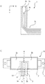
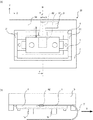
本発明の超音波モータの基本的な構成を図1により説明する。図1(a)は平面図、図1(b)は正面図、図1(c)、(d)は側面図、図1(e)は底面図である。図1において振動板1は、矩形状の平板部と、平板部に設けられた突起部1a及び1bとを有する。突起部1a及び1bは、絞り加工により平板部と一体成型してもよいし、別部材を平板部に接着により固定してもよい。振動板1には高周波振動する圧電素子2が固定されている。圧電素子2は、同方向に分極された2箇所の領域2aと2bとを備え、領域2aがα相に、領域2bがβ相に割り当てられている。圧電素子2は、更に分極されていない領域2cを備えており、領域2cは、図1(b)における圧電素子2の裏面2eの全面電極から側面の2dの領域の電極を経由して導通されたグランドとして使用する電極である。
(Basic configuration of the present invention)
The basic configuration of the ultrasonic motor of the present invention will be described with reference to FIG. 1A is a plan view, FIG. 1B is a front view, FIGS. 1C and 1D are side views, and FIG. 1E is a bottom view. In FIG. 1, the
振動板1の矩形状の面の短辺部には、振動板1と同期して移動し、後述の第2の保持部材5に対し、直接的又は間接的に連結される連結部1c及び1dが設けられている。この連結部1c及び1dは、振動板1と圧電素子2の振動において変位が少ない部分に設けられ、かつ、十分に剛性が弱いので、振動を阻害しにくい形状となっている。したがって、連結部1c及び1dは、振動板1と圧電素子2の振動にはほとんど影響を与えない。更に、連結部1cは固定穴1eを有し、連結部1dは固定穴1fを有する。図1(e)には、後述の短辺方向の曲げ振動の1次の固有振動モードの腹AN(Antinode)と、後述の長辺方向の曲げ振動の2次の固有振動モードの節N1、N、N2(Node)が示されている。ここで、振動板1の長辺方向をX方向、短辺方向をY方向とそれぞれ定義する。また、振動板1の略矩形状の面の厚さ方向をZ方向と定義する。Z方向において、振動板1から後述する摩擦部材7への向きを+Z方向、後述する摩擦部材7から振動板1への向きを−Z方向とそれぞれ定義する。
Connecting portions 1c and 1d that move in synchronization with the
図2は、圧電素子2に給電するための給電手段を示し、図2(a)は給電するためのフレキシブル基板3の構成の一部、図2(b)はフレキシブル基板3を圧電素子2に固定した状態の平面図を示す。フレキシブル基板3は、図2(a)に示すように、ベース基板3d上に電極3a、3b、3cが設けられている。そして、フレキシブル基板3は、図2(b)に示すように、電極3a、3b、3cがそれぞれ圧電素子2の領域2a、2b、2cに対応して電気的に接続されている。更にフレキシブル基板3は、圧電素子2の第1の固定部A1で固定され、図示されていない外部電源において発生した交流電圧を圧電素子2に給電する。
2 shows a power supply means for supplying power to the
フレキシブル基板3が第1の固定部A1から延出して引き出される位置Pは、後述の長辺方向の曲げ振動の2次の固有振動モードの節(図2(b)におけるN線上)となる位置である。また、フレキシブル基板3が第1の固定部A1から延出する方向は、振動板1の移動方向であるX方向及び、振動板1が後述の摩擦部材7に対して加圧される加圧方向であるZ方向に直交するY方向である。なお、これ以降の図では、フレキシブル基板3の電極3a、3b、3cの記載は、簡略化のため省略する。以上説明したとおり、振動板1、圧電素子2及びフレキシブル基板3によって超音波モータ10が構成されている。
A position P at which the
次に、超音波モータ10の保持方法について説明する。図3は、超音波モータ10の保持方法を示す。図3(a)は平面図、図3(b)は底面図であり、図3(c)は図3(b)の断面線c−cにおける断面図である。第1の保持部材4は、Z方向に突出している二つの固定軸4a及び4bを有する。そして、固定軸4a及び4bがそれぞれ振動板1の固定穴1e及び1fに嵌合することにより超音波モータ10が第1の保持部材4に固定される。フレキシブル基板3は、圧電素子2に第1の固定部A1で固定され、位置Pを通り、第1の保持部材4の切り欠き部4cを経て、Y方向に引き出される。更にフレキシブル基板3は、図3(a)における第1の保持部材4の投影領域外まで延出した後、略直角に曲がり、振動板の移動方向であるX方向に延出する。
Next, a method for holding the
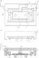
図4は、超音波モータ10を固定した第1の保持部材の更なる保持方法、及び振動板1を付勢する加圧機構を示す。図4(a)は底面図、図4(b)は正面図、図4(c)は図4(a)の断面線c−cにおける断面図である。第1の保持部材4に固定された超音波モータ10は、第2の保持部材5を有する。図4(c)に示すように、第2の保持部材5は、ローラ61が第1の保持部材4側ローラ受け面4dと第2の保持部材5側のローラ受け面5bとの間で転動可能となっている。すなわち、第1の保持部材4は、ローラ61によって第2の保持部材5に対して振動板1の移動方向であるX方向の移動は規制され、振動板1が後述の摩擦部材7に対して加圧される加圧方向であるZ方向の移動は、規制されないように保持されている。更に加圧部材である加圧ばね62が第2の保持部材5と振動板1との間に備えられ、加圧ばね62の上端が第2の保持部材5に作用し、下端が圧電素子2及びフレキシブル基板3に作用する。振動板1は、加圧ばね62の付勢力によって後述の摩擦部材7に対して付勢されながら当接する。このローラ61により、第1の保持部材4は第2の保持部材5に保持され、加圧ばね62により超音波モータ10は付勢されている。
FIG. 4 shows a further holding method of the first holding member to which the
これにより、振動板1は、第1の保持部材4と同期してZ方向に移動することができ、かつ、超音波モータ10の移動方向には、嵌合すき間等によるガタがなく移動することができる。また、振動板1の高周波振動によって超音波モータ10が後述の摩擦部材7に対して移動する際は、超音波モータ10及び第1の保持部材4、第2の保持部材5が同期して移動する。フレキシブル基板3は、図4(a)に示すように、圧電素子2上の第1の固定部A1からY方向へ延出している。そして、フレキシブル基板3は、第2の保持部材5上にて、移動方向のX方向へ屈曲して延出している。駆動部20は、超音波モータ10、第1の保持部材4及び第2の保持部材5等によって構成される。
Thereby, the
図5は、リニア駆動装置30の構成を示し、図5(a)は正面図、図5(b)は底面図、図5(c)は図5(a)の断面線c−cにおける断面図である。なお、図5(b)においては、摩擦部材7及びベース部材71の記載が省略されている。駆動部20の移動に伴いフレキシブル基板3は屈曲変形し、屈曲部3fが移動する。駆動部20は、ベース部材71に固定されたフレキシブル基板3を屈曲変形させながら移動するので、フレキシブル基板3には、図5(a)及び(b)において矢印で示す方向に反力Rが発生する。
5A and 5B show the configuration of the
摩擦部材7は、ベース部材71の底面71a上に固定されている。振動板1の突起部1a及び1bは、加圧されながら摩擦部材7と当接しており、振動板1の高周波振動によって超音波モータ10は摩擦部材7に対して相対移動し、第1の保持部材4及び第2の保持部材5は超音波モータ10と同期して移動する。ベース部材71と第2の保持部材5との間には、転動コロ72が設けられており、駆動の際の摺動抵抗を軽減している。転動コロ72は、駆動の際の摺動抵抗を軽減するために設けられているものであって、転動ボール及びボール溝による転動機構等でもよい。
The
超音波モータ10、第1の保持部材4及び第2の保持部材5によって構成される駆動部20は、振動板1の高周波振動によってベース部材71に対してX方向に移動可能となる。振動板1の突起部1a、1bは、加圧ばね62の加圧力により加圧されながら摩擦部材7に当接する。駆動部20は、後述の図6及び図9において矢印に示すような楕円運動による駆動力によって、X方向に移動することができる。以上が本発明の超音波モータ10の基本構成である。
The
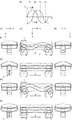
次に、超音波モータ10の圧電素子2の高周波振動によって振動板1の突起部1a及び1bに生成される楕円運動について図6を用いて説明する。圧電素子2の高周波振動は、振動板1に特定の固有振動モードを励振する。すなわち、圧電素子2の高周波振動によって振動板1には、振動板1の短辺方向(Y方向)の曲げ振動の1次の固有振動モードと振動板1の長辺方向(X方向)の曲げ振動の2次の固有振動モードが励振される。図1(e)を参照すると、突起部1a及び1bは、短辺方向の曲げ振動の1次の固有振動モードの腹ANの近傍であって、かつ、長辺方向の曲げ振動の2次の固有振動モードの節N1、N2の近傍に設けられている。又、図1(a)を参照すると、上述の給電手段により、圧電素子2の分極された領域2a(α相)と領域2b(β相)に位相差を+90°から+270°まで変化させた交流電圧を印加することによって、高周波振動を発生させることができる。
Next, the elliptical motion generated in the
図6は、α相に対してβ相の位相を約+90°遅らせて交流電圧を印加した場合の振動の様子を示す。図6(a)は、圧電素子のα相とβ相に印加される交流電圧の変化を示している。図1(b)、(c)、(d)は、それぞれ図6(b)、(c)、(d)に対応している。図6(a)に示す、各時刻T1からT4に対する、突起部の振動状態をP1からP4に示している。また、図6において圧電素子2、連結部1c及び1dの記載は、簡略化のため省略している。
FIG. 6 shows a state of vibration when an AC voltage is applied while delaying the phase of the β phase by about + 90 ° with respect to the α phase. FIG. 6A shows a change in AC voltage applied to the α phase and the β phase of the piezoelectric element. FIGS. 1B, 1C, and 1D correspond to FIGS. 6B, 6C, and 6D, respectively. The vibration states of the protrusions at times T1 to T4 shown in FIG. 6A are indicated by P1 to P4. In FIG. 6, the description of the
α相とβ相に同符号の電圧が印加されている時刻(T2及びT4)には、α相とβ相とが同様に伸縮することにより、短辺方向の曲げ振動の1次の固有振動モードが励振され、突起部1a及び1b先端のZ方向振幅が最大となる(図6(c)のP2、P4における変位z)。一方、α相とβ相に異符号の電圧が印加されている時刻(T1及びT3)には、α相とβ相が逆方向に伸縮することにより、長辺方向の曲げ振動の2次の固有振動モードが励振され、突起部1a及び1b先端のX方向振幅が最大となる(図6(b)のP1、P3における変位x)。α相に対してβ相の位相を約+90°遅らせて交流電圧を印加した結果、突起部1a及び1b先端には、それぞれ楕円運動が発生する。
At the time (T2 and T4) when the voltage of the same sign is applied to the α phase and the β phase (T2 and T4), the α natural phase and the β phase expand and contract in the same manner, so that the primary natural vibration of the bending vibration in the short side direction is obtained. The mode is excited, and the amplitudes in the Z direction at the tips of the
摩擦部材7には、突起部1a及び1bが当接する。突起部1a及び1bの楕円運動により生じる摩擦部材7と突起部1a及び1bとの間の摩擦によって、振動板1は推進力を得て、図6(b)に示すようにX方向に相対移動することができる。又、α相に対してβ相の位相を約+270°遅らせて交流電圧を印加した場合は、反対方向の楕円運動が発生するので、突起部1a及び1bの楕円運動により生じる摩擦部材7との摩擦によって振動板1は、図6(b)に示すX方向とは反対の方向に相対移動することができる。
The
このように、第1の実施形態の超音波モータにおいては、高周波振動により突起部1a及び1bに生成した楕円運動によって、摩擦部材7に対して振動板1が相対移動することが可能である。
As described above, in the ultrasonic motor according to the first embodiment, the
(従来例)
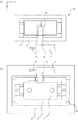
次に、超音波モータの従来例について説明する。図7及び図8は、いずれも従来例における、フレキシブル基板3が変形するという課題を示している。図7(a)は駆動部20の平面図、図7(b)は駆動部20の底面図である。図7(a)では、第2の保持部材5及びローラ61の記載が省略されている。図8(a)はリニア駆動装置30の正面図、図8(b)は図8(a)の断面線b−bにおける断面図である。
(Conventional example)
Next, a conventional example of an ultrasonic motor will be described. 7 and 8 show a problem that the
従来例では、駆動部20の移動に伴うフレキシブル基板3の屈曲変形により、図7の矢印で示す方向に発生した反力Rによって、フレキシブル基板3は、第2の保持部材5に対して相対的にX方向に移動する。これによりフレキシブル基板3の領域Sで示す部分が変形し、フレキシブル基板3を固定(第1の固定部A1)する圧電素子2に負荷が発生する。
In the conventional example, the
図8では、駆動部20の移動に伴うフレキシブル基板3の屈曲変形により発生した反力によって、フレキシブル基板3が矢印で示す方向Dに第2の保持部材5から離れるように変形する。この変形に伴い、第1の固定部A1でフレキシブル基板3が固定されている圧電素子2はZ方向に引っ張られることにより、圧電素子2に負荷が発生する。このような駆動部20の移動に伴い、フレキシブル基板3が変形し圧電素子2に負荷が発生する以外にも、圧電素子2に負荷が発生することが考えられる。
In FIG. 8, the
次に、従来例の超音波モータ10の速度特性について図9を用いて説明する。図9(a)は、駆動部20が駆動端位置(図9(a)において点線で図示)から他の駆動端位置(図9(a)において実線で図示)までの移動を示す図である。ここで、駆動部20を駆動端位置(1)から駆動端位置(2)まで移動させた際の駆動ストロークはXsである。駆動部20が移動する際に、超音波モータ10には、ある一定の周波数及び位相差の電圧が入力される。図9(b)は、入力に対し駆動される超音波モータ10の速度特性を示す。図の横軸は駆動部20の位置X、縦軸は駆動部20の移動速度vを示す。
Next, the speed characteristics of the conventional
図9(c)は、図9(b)の領域Xnにおける突起部1a及び1bの楕円運動を示している。図9(d)は、図9(b)の領域Xrにおける突起部1a及び1bの楕円運動を示している。突起部1a及び1b先端に発生する楕円運動のうち、振動板1の移動方向の振幅をAX、振動板1を摩擦部材7に加圧する加圧方向の振幅をAZとして示している。なお、図9(c)、(d)において、突起部1a及び1b先端の楕円運動は、簡略化のため円運動として示されている。
FIG. 9C shows the elliptical motion of the
駆動部20は、位置Xが0からX1までの所定の領域で加速し、駆動部20の移動速度vは、ある一定の周波数及び位相差での移動速度v1となる。X1からX2までの領域Xnは、圧電素子2への負荷がない領域である。一方、X2からXsまでの領域Xrは、図7もしくは図8に示したような、フレキシブル基板3の変形によって圧電素子2に負荷が発生する領域である。
領域Xrにおいては、フレキシブル基板3の変形に起因する圧電素子2への負荷によって、振動が阻害されるため、図9(d)に示すとおり、領域Xnにおける楕円運動(図9(d)の点線で図示)よりも楕円運動が小さくなる。すなわち、領域Xrにおける突起部1a及び1bの振幅AX2、AZ2は、領域Xnにおける振幅AX1、AZ1よりも小さくなる。振動板1の移動速度vには、突起部1a及び1bの楕円運動の移動方向の振幅AXが寄与する。このため、領域Xrにおいて、振動が阻害されて図9(d)の振幅AX2に示すように、移動方向の振幅Axが小さくなると、図9(b)に示すように振動板1の移動速度vは低下してしまう。
In the region Xr , since the vibration is hindered by the load on the
このように、従来例には、高周波振動する圧電素子2にフレキシブル基板3の屈曲変形による負荷が生じることにより、駆動部20の移動に必要な圧電素子2の高周波振動が阻害され、駆動部20の移動速度が低下、すなわち駆動効率が低下するという課題がある。
As described above, in the conventional example, a load caused by bending deformation of the
(第1の実施形態)
次に、第1の実施形態について、図10を用いて説明する。図10(a)は、第1の実施形態に係るフレキシブル基板3の固定方法を示す底面図、図10(b)は正面図である。主要な構成は、図4に示した構成と同じである。フレキシブル基板3は、両面粘着テープ等の接着手段により第2の保持部材5の固定面5a上に第2の固定部A2で固定されている。このとき、フレキシブル基板3は、圧電素子2上の第1の固定部A1から延出する方向の延長線上(N)で第2の保持部材5に固定されている。すなわち、第2の固定部A2は、フレキシブル基板3が第1の固定部A1から延出する方向の延長線上(N)に設けられている。フレキシブル基板3は、第2の固定部A2で固定された後、移動方向のX方向へ延出している。なお、図10(a)に示す延長線Nの位置は、長辺方向の曲げ振動の2次の固有振動モードの節の位置でもある。
(First embodiment)
Next, a first embodiment will be described with reference to FIG. FIG. 10A is a bottom view showing a fixing method of the
フレキシブル基板3が第2の保持部材5に固定される第2の固定部A2は、第1の固定部A1と屈曲部3fとの間である。すなわち、フレキシブル基板3は両面粘着テープにより第2の固定部A2において固定されており、駆動部20の移動に伴うフレキシブル基板3の屈曲変形によって発生する反力を第2の固定部A2で受ける。第2の保持部材5は十分な剛性を持った部材であるため、フレキシブル基板3の屈曲変形によって発生する反力でフレキシブル基板3の第2の固定部A2が圧電素子2の固定部Aに対して相対的に移動することはない。すなわち、第2の固定部A2から第1の固定部A1までの領域のフレキシブル基板3が変形することはないため、圧電素子2には負荷は伝達されない。
The second fixing portion A2 where the
なお、フレキシブル基板3は、第2の固定部A2から移動方向のX方向に延出した後、屈曲部3fで屈曲し折り返してベース部材71の底面71aに沿ってX方向とは反対の方向に延出する。フレキシブル基板3は、ベース部材71の底面71a上の後述の固定ボス71bにより固定されている。
The
ここで、フレキシブル基板3の共振現象による不要振動の発生について説明する。圧電素子2の高周波振動により、圧電素子2に固定されたフレキシブル基板3に振動が伝達される。このとき、圧電素子2上の第1の固定部A1と第2の保持部材5上の第2の固定部A2との間のフレキシブル基板3が両端固定梁の状態で振動するため、特定の固有振動モードが存在する。圧電素子2の高周波振動の周波数と、フレキシブル基板3が有する固有振動モードの共振周波数とが一致すると、共振現象によりフレキシブル基板3に不要振動が発生し、圧電素子2の高周波振動を阻害し、不要音が発生するといった問題が生じる。
Here, generation of unnecessary vibration due to the resonance phenomenon of the
このため、圧電素子2に発生させる高周波振動の周波数は、圧電素子2上の第1の固定部A1と第2の保持部材5上の第2の固定部A2との間のフレキシブル基板3の固有振動モードの共振周波数と異なるように、フレキシブル基板3の形状もしくは寸法を設計する。例えば、圧電素子2上の第1の固定部A1と第2の保持部材5上の第2の固定部A2との間のフレキシブル基板3の共振を、図10(a)の底面図に示すように長さl、幅bの平板の共振として考える。このとき、平板の共振周波数fは、以下の式(1)で与えられる。

ここで、εrは比誘電率、m及びnはそれぞれ長さ方向及び幅方向の振動モード番号である。すなわち、長さ方向のm次の振動モードの共振周波数には長さlの逆数が寄与し、幅方向のn次の振動モードの共振周波数には幅bの逆数が寄与する。このため、前述した不要振動の振動モードが長さ方向の振動モードであれば長さlの寸法を、幅方向の振動モードであれば幅bの寸法を調整することで不要振動の共振周波数が変化する。具体的には、長さlは第2の固定部A2のY方向の位置を変更することで、幅bはフレキシブル基板3の幅寸法を変更することでそれぞれ調整可能である。このようにして、フレキシブル基板3の寸法を変更することで不要振動の共振周波数を調整し、圧電素子2の高周波振動の周波数と異なるようにすることができる。
Here, ε r is a relative dielectric constant, and m and n are vibration mode numbers in the length direction and the width direction, respectively. That is, the reciprocal of the length l contributes to the resonance frequency of the m-th vibration mode in the length direction, and the reciprocal of the width b contributes to the resonance frequency of the n-th vibration mode in the width direction. Therefore, if the vibration mode of the unnecessary vibration described above is the vibration mode in the length direction, the dimension of the length l is adjusted, and if the vibration mode of the width direction is the vibration mode in the width direction, the resonance frequency of the unnecessary vibration is adjusted. Change. Specifically, the length l can be adjusted by changing the position of the second fixing portion A2 in the Y direction, and the width b can be adjusted by changing the width dimension of the
図11は、リニア駆動装置30において駆動部20がX方向に移動する様子を示した図である。図11(a)は、駆動部20が駆動端開始位置、(b)は中心位置、(c)は駆動端終了位置に位置する場合を示している。駆動部20がX方向に移動する場合、駆動端開始位置から移動を開始し、中間位置を通過して駆動端終了位置で停止する。X方向と反対の方向に移動する場合には、この移動の逆である。フレキシブル基板3は、両面粘着テープ等の接着手段により第2の保持部材5に固定されている。さらに、フレキシブル基板3は、第2の固定部A2からX方向に延出し、屈曲部3fで折り返した後にベース部材に沿ってX方向とは反対の方向に延出し、固定ボス71bによりベース部材71上に固定されている。駆動部20の移動に伴いフレキシブル基板3は、屈曲変形しながら屈曲部3fが移動する。固定されたベース部材71に対して駆動部20が移動する本発明のような構成においては、上記のように屈曲部3fを有するフレキシブル基板3によって駆動部20と一体となって移動する圧電素子2に給電する構成となる。
FIG. 11 is a diagram illustrating a state in which the
図12は、第1の実施形態の超音波モータ10を利用したリニア駆動装置30の速度特性を示す図であり、横軸が駆動部20の位置X、縦軸が駆動部20の移動速度vである。駆動部20は、位置Xが0からX1までの所定の領域で加速し、駆動部20の移動速度vは、ある一定の周波数及び位相差での移動速度v1となる。従来例における圧電素子2に負荷が発生していた領域Xr(図9(b)参照)において、第1の実施形態では、フレキシブル基板3に起因する負荷が圧電素子2へ伝達されない。このため、圧電素子2の高周波振動は阻害されずに、駆動部20は一定の移動速度v1でXsまで移動することができる。このように、第1の実施形態においては、圧電素子2の高周波振動が阻害されないため、従来のフレキシブル基板が第2の保持部材5に固定されていない構成と比較して移動速度が低下しない。すなわち、超音波モータ10の駆動効率が向上する。
FIG. 12 is a diagram illustrating speed characteristics of the
以上説明したとおり、第1の実施形態の超音波モータ10は、フレキシブル基板3が第2の保持部材5に固定されているため、フレキシブル基板3の屈曲変形による負荷が圧電素子2に伝達されない。この結果、フレキシブル基板3の屈曲変形による振動阻害を抑制し、駆動効率の向上を達成するという効果を奏する。
As described above, in the
なお、第1の実施形態では、第2の固定部A2が第1の固定部A1から延出する方向の延長線上(N)である例を示したが、第1の固定部A1から延出する方向の延長線上(N)ではない位置であっても良い。フレキシブル基板3は、長辺方向の曲げ振動の2次の固有振動モードの節(N1、N、N2)となる位置から引き出されているため、第1の固定部A1から延出する方向の延長線上(N)で第2の保持部材5に固定することによって、フレキシブル基板3の不要振動が発生しにくい。しかしながら、第2の固定部A2が延出する方向の延長線上(N)でない位置であっても、第2の固定部A2が屈曲部3fと第1の固定部A1との間で設けられていれば、フレキシブル基板3の屈曲変形による負荷は、圧電素子2に伝達されないため駆動効率が低下しない。又、第1の実施形態では両面粘着テープによりフレキシブル基板3を第2の保持部材5に固定する方法について述べたが、固定するための接着手段は両面粘着テープに限られない。
In the first embodiment, the example in which the second fixing portion A2 is on the extension line (N) in the direction extending from the first fixing portion A1 has been described. However, the second fixing portion A2 extends from the first fixing portion A1. It may be a position that is not on the extension line (N) in the direction. Since the
(第2の実施形態)
以下、本発明の第2の実施形態について、図13を用いて説明する。第1の実施形態では、フレキシブル基板3が両面粘着テープにより第2の保持部材5に固定されている。しかしながら、第2の実施形態では、フレキシブル基板3が第2の保持部材5に対してX方向及びZ方向の移動は規制され、Y方向の移動は規制されないように第2の保持部材5に固定されている。なお、第1の実施形態と同一部材のものは同一記号で図示される。また、第1の実施形態と同じところは説明を省略し、第1の実施形態と異なるところだけを説明する。
(Second Embodiment)
Hereinafter, a second embodiment of the present invention will be described with reference to FIG. In the first embodiment, the
図13は、フレキシブル基板3の保持方法の第2の実施形態を示す。図13(a)は、駆動部20の底面図、図13(b)は駆動部20の正面図である。フレキシブル基板3上に設けられた固定穴3eと第2の保持部材5上に設けられた固定ボス5c(突起)とを嵌合させることにより、フレキシブル基板3は、第2の保持部材5の固定面5a上に第2の固定部A2で固定されている。ここで、固定穴3eは、Y方向に長い長穴となっている。そのため、フレキシブル基板3は、振動板1の移動方向であるX方向と、振動板1の加圧方向であるZ方向の移動は規制され、移動方向であるX方向と加圧方向であるZ方向とに直交する方向であるY方向の移動は、規制されないように第2の保持部材5に固定されている。
FIG. 13 shows a second embodiment of the method for holding the
次に、第2の実施形態の作用、効果について図14を用いて説明する。図14(a)〜(c)は、第1の保持部材4の第2の保持部材5に対する相対的な位置が変化した状態を示している。図14(a)及び(b)は、第1の実施形態の図10(a)の断面線a−aにおける断面図であり、図14(c)は、第2の実施形態の図13(a)の断面線c−cにおける断面図である。
Next, the operation and effect of the second embodiment will be described with reference to FIG. 14A to 14C show a state in which the relative position of the first holding
第2の保持部材5が第1の保持部材4を保持する構成において、図14(a)のように、第1の固定部A1と第2の固定部A2とが同一平面となるように構成して、フレキシブル基板3を第2の固定部A2に両面粘着テープにより固定する(第1の実施形態)。しかしながら、部品公差の積み重ね等により、図14(b)のように、振動板1及び圧電素子2を保持する第1の保持部材4が第2の保持部材5に対して、Z方向にズレ量δだけ相対的に位置が変化する場合がある。このズレ量δが発生すると、第1の固定部A1と第2の固定部A2との間には引張荷重が発生する。発生した引張荷重は、圧電素子2の高周波振動を阻害するため駆動効率が低下する。すなわち、第1の実施形態では、場合によっては駆動効率が低下する問題がある。
In the configuration in which the second holding
しかしながら、第2の実施形態のように、フレキシブル基板3を第2の保持部材5に対してY方向の移動が規制されないように固定することで、図14(c)に示すようにフレキシブル基板3は第2の保持部材5に対してY方向に移動することができる。このため、第1の固定部A1と第2の固定部A2との間に引張荷重が発生せず、結果として圧電素子2の高周波振動を阻害することなく、駆動効率が低下しないという効果を奏する。
However, as shown in FIG. 14C, the
第2の実施形態のように、X方向とZ方向の移動が規制され、Y方向の移動が規制されないようにフレキシブル基板3を第2の保持部材5に固定さえすれば、どのような固定方法でも良い。例えば、図15は、第2の実施例の変形例を示し、フレキシブル基板3は固定爪5dによって固定されている。図15(a)は駆動部20の底面図、図15(b)は図15(a)の断面線b−bにおける断面図である。フレキシブル基板3を固定する固定爪5dは、X方向に離間した二つの要素で構成されている。そして、二つの固定爪5dは、X方向及びZ方向の移動が規制されるように、且つY方向には移動が規制されないようにフレキシブル基板3を固定している。
As in the second embodiment, any fixing method can be used as long as the
(第3の実施形態)
以下、本発明の第3の実施形態について図16を用いて説明する。第3の実施形態では、フレキシブル基板3が第1の保持部材4に固定されている点が第1の実施形態とは異なっている。なお、第1の実施形態と同一部材のものは、同一記号で図示される。また、第1の実施形態と同じところは説明を省略し、第1の実施形態と異なるところだけを説明する。
(Third embodiment)
Hereinafter, a third embodiment of the present invention will be described with reference to FIG. The third embodiment is different from the first embodiment in that the
図16(a)は、駆動部20の底面図、図16(b)は正面図である。なお、図16(b)において第2の保持部材5の記載は省略されている。図16において、フレキシブル基板3は、両面粘着テープにより第1の保持部材4の固定面4e上に第2の固定部A2で固定されている。すなわち、フレキシブル基板3は、圧電素子2に固定されている第1の固定部A1と、第1の保持部材4に固定されている第2の固定部A2と、振動板1の移動に伴い屈曲変形する屈曲部3fとを備え、第2の固定部A2は、第1の固定部A1と屈曲部3fとの間に備えられる。また、フレキシブル基板3は、圧電素子2上の第1の固定部A1から延出する方向の延長線上(N)で第1の保持部材4に固定されている。すなわち、第2の固定部A2は、フレキシブル基板3が第1の固定部A1から延出する方向の延長線上(N)に設けられている。
16A is a bottom view of the
フレキシブル基板3が第2の保持部材5に固定されている第1の実施形態では、図14(b)のようにZ方向にズレ量δだけ相対的な位置が変化すると、第1の固定部A1と第2の固定部A2との間に引張荷重が発生し、圧電素子2の高周波振動を阻害し駆動効率が低下する。しかしながら、第3の実施形態のように、フレキシブル基板3を第1の保持部材4に固定することによって、フレキシブル基板3の屈曲変形による負荷が圧電素子2に伝達されないようにしている。すなわち、Z方向にズレ量δだけ相対的な位置が変化した場合にも、第1の固定部A1と第2の固定部A2との間には引張荷重が発生しないため、圧電素子2の高周波振動を阻害することがなく、駆動効率が低下しないという効果を奏する。
In the first embodiment in which the
以上、本発明の好ましい実施形態について説明したが、本発明はこれらの実施形態に限定されず、その要旨の範囲内で種々の変形及び変更が可能である。 As mentioned above, although preferable embodiment of this invention was described, this invention is not limited to these embodiment, A various deformation | transformation and change are possible within the range of the summary.
本発明は、小型軽量かつ広い駆動速度レンジが要求される電子機器、特にレンズ駆動装置等に利用可能である。 The present invention can be used for electronic devices that are required to be small and light and have a wide driving speed range, in particular, lens driving devices and the like.
1 振動板
1a、1b 突起部
1c、1d 連結部
1e、1f 固定穴
2 圧電素子
2a、2b、2c 領域
2d 側面の領域
2e 裏面
3 フレキシブル基板
3a、3b、3c 電極
3d ベース基板
3e 固定穴
3f 屈曲部
4 第1の保持部材
4a、4b 固定軸
4c 切り欠き部
4d 第1の保持部材4側ローラ受け面
4e 固定面
5 第2の保持部材
5a 固定面
5b 第2の保持部材5側ローラ受け面
5c 固定ボス
5d 固定爪
61 ローラ
62 加圧ばね
7 摩擦部材
71 ベース部材
71a 底面
71b 固定ボス
72 転動コロ
10 超音波モータ
20 駆動部
30 リニア駆動装置
A1 第1の固定部
A2 第2の固定部
DESCRIPTION OF
Claims (8)
前記振動板に固定され高周波振動する圧電素子と、
該圧電素子に固定され該圧電素子に給電するためのフレキシブル基板と、
前記振動板を保持するための保持部材と、
前記振動板を付勢するための加圧部材と、
前記振動板が加圧部材により付勢され当接する摩擦部材と、
を有し、
前記振動板は、前記圧電素子の高周波振動により前記摩擦部材に対して移動し、
前記フレキシブル基板は、前記圧電素子に固定される第1の固定部と、前記保持部材に固定される第2の固定部と、前記振動板の移動に伴い屈曲変形する屈曲部と、を備え、
前記第2の固定部は、前記第1の固定部と前記屈曲部との間に設けられていることを特徴とする駆動装置。 A diaphragm having a substantially rectangular flat plate portion and a protrusion provided on the flat plate portion;
A piezoelectric element that is fixed to the diaphragm and vibrates at a high frequency;
A flexible substrate fixed to the piezoelectric element and supplying power to the piezoelectric element;
A holding member for holding the diaphragm;
A pressure member for biasing the diaphragm;
A friction member in which the diaphragm is urged and abutted by a pressure member;
Have
The diaphragm moves with respect to the friction member by high-frequency vibration of the piezoelectric element,
The flexible substrate includes a first fixing portion that is fixed to the piezoelectric element, a second fixing portion that is fixed to the holding member, and a bending portion that is bent and deformed as the diaphragm moves.
The drive device according to claim 1, wherein the second fixing portion is provided between the first fixing portion and the bent portion.
前記フレキシブル基板は、該第1の保持部材と該第2の保持部材のいずれかに固定されていることを特徴とする、請求項1又は2に記載の駆動装置。 The holding member is divided into a first holding member for holding the diaphragm and a second holding member for holding the first holding member;
The driving apparatus according to claim 1, wherein the flexible substrate is fixed to either the first holding member or the second holding member.
Priority Applications (2)
| Application Number | Priority Date | Filing Date | Title |
|---|---|---|---|
| JP2014234105A JP6463951B2 (en) | 2014-11-19 | 2014-11-19 | Drive device |
| US14/937,283 US10103650B2 (en) | 2014-11-19 | 2015-11-10 | Driving device |
Applications Claiming Priority (1)
| Application Number | Priority Date | Filing Date | Title |
|---|---|---|---|
| JP2014234105A JP6463951B2 (en) | 2014-11-19 | 2014-11-19 | Drive device |
Publications (2)
| Publication Number | Publication Date |
|---|---|
| JP2016100928A true JP2016100928A (en) | 2016-05-30 |
| JP6463951B2 JP6463951B2 (en) | 2019-02-06 |
Family
ID=55962601
Family Applications (1)
| Application Number | Title | Priority Date | Filing Date |
|---|---|---|---|
| JP2014234105A Active JP6463951B2 (en) | 2014-11-19 | 2014-11-19 | Drive device |
Country Status (2)
| Country | Link |
|---|---|
| US (1) | US10103650B2 (en) |
| JP (1) | JP6463951B2 (en) |
Cited By (4)
| Publication number | Priority date | Publication date | Assignee | Title |
|---|---|---|---|---|
| JP2017225294A (en) * | 2016-06-17 | 2017-12-21 | ミネベアミツミ株式会社 | Rotary device and vehicle including air conditioning system including the same |
| JP2019221073A (en) * | 2018-06-20 | 2019-12-26 | キヤノン株式会社 | Vibration wave motor and drive unit |
| JP2020005353A (en) * | 2018-06-26 | 2020-01-09 | キヤノン株式会社 | Vibration wave motor and driving device using vibration wave motor |
| JP2020137237A (en) * | 2019-02-19 | 2020-08-31 | キヤノン株式会社 | Vibration wave motor, and lens barrel driving apparatus having vibration wave motor |
Families Citing this family (4)
| Publication number | Priority date | Publication date | Assignee | Title |
|---|---|---|---|---|
| JP6829555B2 (en) | 2016-06-23 | 2021-02-10 | キヤノン株式会社 | Vibration wave motor and lens drive |
| JP6605012B2 (en) | 2017-12-08 | 2019-11-13 | キヤノン株式会社 | Vibration wave motor and lens driving device using vibration wave motor |
| JP2019195233A (en) | 2018-05-01 | 2019-11-07 | キヤノン株式会社 | Vibration wave motor and driving unit with the vibration wave motor |
| JP7112250B2 (en) | 2018-05-24 | 2022-08-03 | キヤノン株式会社 | Oscillating wave motor and drive |
Citations (2)
| Publication number | Priority date | Publication date | Assignee | Title |
|---|---|---|---|---|
| JP2006081006A (en) * | 2004-09-10 | 2006-03-23 | Konica Minolta Photo Imaging Inc | Camera with shake correction mechanism |
| JP2012227988A (en) * | 2011-04-15 | 2012-11-15 | Canon Inc | Vibration type linear actuator and optical apparatus using the same |
Family Cites Families (7)
| Publication number | Priority date | Publication date | Assignee | Title |
|---|---|---|---|---|
| JP4331531B2 (en) | 2003-08-06 | 2009-09-16 | オリンパス株式会社 | Vibration wave linear motor and lens device using the same |
| JP4276914B2 (en) * | 2003-09-18 | 2009-06-10 | オリンパス株式会社 | Vibration wave linear motor and driving method thereof |
| US7969065B2 (en) * | 2008-09-09 | 2011-06-28 | Canon Kabushiki Kaisha | Vibration wave driving device |
| JP2011045208A (en) * | 2009-08-24 | 2011-03-03 | Olympus Corp | Ultrasonic motor |
| JP5467821B2 (en) * | 2009-09-07 | 2014-04-09 | パナソニック株式会社 | Vibration type actuator |
| JP2012044832A (en) * | 2010-08-23 | 2012-03-01 | Canon Inc | Oscillatory wave driving device and image blur correction device |
| WO2013002298A1 (en) * | 2011-06-27 | 2013-01-03 | Canon Kabushiki Kaisha | Piezoelectric element, oscillatory wave motor, and optical apparatus |
-
2014
- 2014-11-19 JP JP2014234105A patent/JP6463951B2/en active Active
-
2015
- 2015-11-10 US US14/937,283 patent/US10103650B2/en active Active
Patent Citations (2)
| Publication number | Priority date | Publication date | Assignee | Title |
|---|---|---|---|---|
| JP2006081006A (en) * | 2004-09-10 | 2006-03-23 | Konica Minolta Photo Imaging Inc | Camera with shake correction mechanism |
| JP2012227988A (en) * | 2011-04-15 | 2012-11-15 | Canon Inc | Vibration type linear actuator and optical apparatus using the same |
Cited By (9)
| Publication number | Priority date | Publication date | Assignee | Title |
|---|---|---|---|---|
| JP2017225294A (en) * | 2016-06-17 | 2017-12-21 | ミネベアミツミ株式会社 | Rotary device and vehicle including air conditioning system including the same |
| US10770951B2 (en) | 2016-06-17 | 2020-09-08 | Minebea Mitsumi Inc. | Rotary apparatus and vehicle having air conditioning system including the rotating apparatus |
| US11689078B2 (en) | 2016-06-17 | 2023-06-27 | Minebea Mitsumi Inc. | Rotary apparatus and vehicle having air conditioning system including the rotating apparatus |
| JP2019221073A (en) * | 2018-06-20 | 2019-12-26 | キヤノン株式会社 | Vibration wave motor and drive unit |
| US11245343B2 (en) | 2018-06-20 | 2022-02-08 | Canon Kabushiki Kaisha | Vibration wave motor and driving device |
| JP7094792B2 (en) | 2018-06-20 | 2022-07-04 | キヤノン株式会社 | Vibration wave motor and drive |
| JP2020005353A (en) * | 2018-06-26 | 2020-01-09 | キヤノン株式会社 | Vibration wave motor and driving device using vibration wave motor |
| JP7098438B2 (en) | 2018-06-26 | 2022-07-11 | キヤノン株式会社 | Vibration wave motor and drive device using vibration wave motor |
| JP2020137237A (en) * | 2019-02-19 | 2020-08-31 | キヤノン株式会社 | Vibration wave motor, and lens barrel driving apparatus having vibration wave motor |
Also Published As
| Publication number | Publication date |
|---|---|
| US10103650B2 (en) | 2018-10-16 |
| JP6463951B2 (en) | 2019-02-06 |
| US20160141979A1 (en) | 2016-05-19 |
Similar Documents
| Publication | Publication Date | Title |
|---|---|---|
| JP6463951B2 (en) | Drive device | |
| US10171008B2 (en) | Vibration wave motor and driving apparatus using the vibration wave motor | |
| JP5765993B2 (en) | Vibration type driving device | |
| US11063205B2 (en) | Vibration actuator and method for manufacturing the same | |
| JP2014018027A (en) | Vibration type actuator, imaging apparatus, and stage | |
| JP2009017735A (en) | Ultrasonic motor | |
| JP2015080329A (en) | Vibrator for vibration type drive device, vibration type drive device, interchangeable lens, imaging device, and automatic stage | |
| JP6422248B2 (en) | Driving device and lens driving device having the same | |
| JP6381326B2 (en) | Ultrasonic motor | |
| JP2016226129A (en) | Vibration wave motor | |
| JP6576214B2 (en) | Vibration type actuator, lens barrel, imaging device and stage device | |
| US10924037B2 (en) | Vibration motor that prevents resonance of contact member, and electronic apparatus | |
| JP2017200374A (en) | Vibration type actuator and electronic apparatus | |
| JP2016032351A (en) | Vibration type actuator, optical equipment, and imaging apparatus | |
| JP6708472B2 (en) | Vibration wave motor and optical device equipped with the vibration wave motor | |
| US20080278034A1 (en) | Driving device | |
| JP6639244B2 (en) | Vibration type actuator and electronic equipment | |
| CN107947626B (en) | Motor using vibrator and electronic device | |
| WO2016002917A1 (en) | Vibration-type actuator, lens barrel, image-capturing device, and automatic stage | |
| JP2022057781A (en) | Vibration-type drive device and device with the same | |
| JP6774222B2 (en) | Vibration wave motor and optical device using vibration wave motor | |
| JP6929165B2 (en) | Vibration wave motor and drive | |
| JP2017060342A (en) | Vibration wave motor | |
| JP4554261B2 (en) | Drive device | |
| JP6273137B2 (en) | Motor and device with motor |
Legal Events
| Date | Code | Title | Description |
|---|---|---|---|
| A621 | Written request for application examination |
Free format text: JAPANESE INTERMEDIATE CODE: A621 Effective date: 20171106 |
|
| RD05 | Notification of revocation of power of attorney |
Free format text: JAPANESE INTERMEDIATE CODE: A7425 Effective date: 20171214 |
|
| RD04 | Notification of resignation of power of attorney |
Free format text: JAPANESE INTERMEDIATE CODE: A7424 Effective date: 20180126 |
|
| A977 | Report on retrieval |
Free format text: JAPANESE INTERMEDIATE CODE: A971007 Effective date: 20180808 |
|
| A131 | Notification of reasons for refusal |
Free format text: JAPANESE INTERMEDIATE CODE: A131 Effective date: 20180828 |
|
| A521 | Request for written amendment filed |
Free format text: JAPANESE INTERMEDIATE CODE: A523 Effective date: 20181022 |
|
| TRDD | Decision of grant or rejection written | ||
| A01 | Written decision to grant a patent or to grant a registration (utility model) |
Free format text: JAPANESE INTERMEDIATE CODE: A01 Effective date: 20181206 |
|
| A61 | First payment of annual fees (during grant procedure) |
Free format text: JAPANESE INTERMEDIATE CODE: A61 Effective date: 20190107 |
|
| R151 | Written notification of patent or utility model registration |
Ref document number: 6463951 Country of ref document: JP Free format text: JAPANESE INTERMEDIATE CODE: R151 |