JP7085196B2 - Vegetable shredding device - Google Patents
Vegetable shredding device Download PDFInfo
- Publication number
- JP7085196B2 JP7085196B2 JP2018110692A JP2018110692A JP7085196B2 JP 7085196 B2 JP7085196 B2 JP 7085196B2 JP 2018110692 A JP2018110692 A JP 2018110692A JP 2018110692 A JP2018110692 A JP 2018110692A JP 7085196 B2 JP7085196 B2 JP 7085196B2
- Authority
- JP
- Japan
- Prior art keywords
- blade
- disk
- shaped blade
- connecting portion
- shaft
- Prior art date
- Legal status (The legal status is an assumption and is not a legal conclusion. Google has not performed a legal analysis and makes no representation as to the accuracy of the status listed.)
- Active
Links
Images


Landscapes
- Food-Manufacturing Devices (AREA)
Description
本発明は、キャベツ等を切断する野菜細断装置に関する。 The present invention relates to a vegetable shredding device for cutting cabbage and the like.
従来の野菜細断装置として、特許文献1に開示されたものがある。特許文献1に開示される野菜細断装置は、上板に穿設した通孔内で水平に回転するように構成した円板状刃物と、上板上に回転自在に支持され、円板状刃物と同方向に回転するように構成された、野菜等を収納する円筒状の回転ドラムとを備える。そして、円板状刃物に設けられた、回転ドラムの回転方向と同方向に回転する円弧状刃が、少なくとも回転ドラムの半径にわたって位置するよう構成される。回転ドラムと円板状刃物が電動モータにより駆動することで、回転ドラムに収納された野菜が細断される。
As a conventional vegetable shredding device, there is one disclosed in
野菜を切断する円板状刃物は消耗品であるため、円板状刃物は、それを回転させる刃物用シャフトを通る棒状の固定具を用いて着脱可能に固定される。例えば円板状刃物の中心に形成された雌ねじと固定具の先端に形成された雄ねじによりねじ締結することで連結して、円板状刃物は刃物用シャフトに固定されていた。しかしながら、ねじ締結による固定では、使用者によって締付け力のばらつきが生じるため緩みが発生するときがある。そのため、円板状刃物が刃物用シャフトから浮いてしまい、野菜の切断(繊切)厚さが不揃いになったり、回転ドラムを削ってしまったりする場合があった。そこで、緩みが発生しないよう、円板状刃物と刃物用シャフトとを一定の締め付け力で固定することが望まれていた。 Since the disc-shaped blade for cutting vegetables is a consumable item, the disc-shaped blade is detachably fixed by using a rod-shaped fixture that passes through a blade shaft that rotates the disc-shaped blade. For example, the disc-shaped blade was fixed to the blade shaft by connecting by screwing with a female screw formed in the center of the disc-shaped blade and a male screw formed at the tip of the fixture. However, in the case of fixing by screwing, loosening may occur because the tightening force varies depending on the user. As a result, the disc-shaped blade may float from the blade shaft, resulting in uneven cutting (fine cutting) thickness of vegetables or scraping of the rotating drum. Therefore, it has been desired to fix the disc-shaped blade and the blade shaft with a constant tightening force so that loosening does not occur.
1つの側面では、野菜を細断する円板状刃物が一定の締め付け力で固定される野菜細断装置を提供することを目的とする。 On one side, it is an object of the present invention to provide a vegetable shredding device in which a disc-shaped blade for shredding vegetables is fixed with a constant tightening force.
1つの形態によれば、野菜を細断する野菜細断装置であって、回転する回転軸部を有する駆動部と、回転軸部に着脱可能に取り付けられ、駆動部により回転されることで野菜を細断する円板状刃物と、を備え、駆動部は、回転軸部の先端に連結部又は被連結部を備え、円板状刃物は、円板状刃物の裏面の中心に、駆動部の連結部に連結する被連結部、又は、駆動部の被連結部に連結する連結部を、備え、被連結部は、連結部が挿入される中空部を有するよう筒状に形成されるとともに、連結部が挿入される端部から延びて折返し部を有する曲がり形状の第一案内溝が形成され、連結部は、一端に被連結部の中空部に挿入可能に形成される挿入部と、挿入部の外周面から突出して第一案内溝を摺動するピンと、他端に挿入部が被連結部の中空部に挿入されたとき、被連結部から離れる方向に連結部を付勢する第一弾性部と、を備える、野菜細断装置が提供される。 According to one form, it is a vegetable shredding device for shredding vegetables, which is detachably attached to a drive unit having a rotating shaft portion and a rotating shaft portion, and is rotated by the drive unit to obtain vegetables. The drive unit is provided with a connecting portion or a connected portion at the tip of the rotating shaft portion, and the disk-shaped cutting tool is provided at the center of the back surface of the disk-shaped cutting tool. It is provided with a connected portion to be connected to the connected portion of the above, or a connected portion to be connected to the connected portion of the drive portion, and the connected portion is formed in a cylindrical shape so as to have a hollow portion into which the connecting portion is inserted. A curved first guide groove is formed extending from the end where the connecting portion is inserted and having a folded portion, and the connecting portion has an insertion portion formed at one end so as to be insertable into the hollow portion of the connected portion. A pin that protrudes from the outer peripheral surface of the insertion portion and slides on the first guide groove, and when the insertion portion is inserted into the hollow portion of the connected portion at the other end, the connecting portion is urged in a direction away from the connected portion. A vegetable shredding device comprising one elastic portion is provided.
開示の野菜細断装置により、円板状刃物が一定の締め付け力で固定される。 The disc-shaped blade is fixed with a constant tightening force by the disclosed vegetable shredding device.
以下、添付図面を用いて本出願の実施の形態を、具体的な実施例に基づいて詳細に説明する。また、以下の実施の形態において同一又は類似の要素には共通の参照符号を付けて示し、理解を容易にするために、これらの図面は縮尺を適宜変更している。 Hereinafter, embodiments of the present application will be described in detail with reference to the accompanying drawings, based on specific examples. Further, in the following embodiments, the same or similar elements are designated by a common reference numeral, and the scales of these drawings are appropriately changed in order to facilitate understanding.
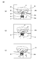
本実施形態の野菜細断装置1は、図1及び図2に示すように、基台10と、切断する野菜を収容する回転ドラム11と、回転ドラム11を載置する上板12と、野菜を切断する円板状刃物20とを備える。また、円板状刃物20によって切断された野菜の飛散を防止する飛散防止カバー13が設けられている。上板12には水平方向にて中央部から前側に偏心した位置に開口部12aが形成されている。基台10には、軸受を介して刃物用シャフト17が回転可能に支持されている。刃物用シャフト17は上板12の開口部12aの中央位置で鉛直方向に起立している。刃物用シャフト17の上端部には、上板12との上面の高さと円板状刃物20の高さとに差ができるよう円板状刃物20が取付けられる。円板状刃物20は、刃物用シャフト17の回転によって回転し、回転ドラム11の野菜を繊切りする。このとき、繊切りされたキャベツ等の野菜の幅が、上板12の上面の高さと円板状刃物20の差によって決まる。そして、野菜細断装置1は、繊切りする野菜の幅を変更可能にするため、図1に示すように上板12の高さを調節する高さ調節ねじ19が、上板12の一方の側部に設けられている。上板12の他方の側部は基台10に軸支されている。使用者が高さ調節ねじ19を回転することで上板12が上下に移動し、上板12の上面の高さと円板状刃物20の高さとの差が変更される。
As shown in FIGS. 1 and 2, the
野菜細断装置1の基台10は、上板12が取付けられる受枠14と、回転ドラム11のドラム用シャフト16と、円板状刃物20が取付けられる刃物用シャフト17を支持する中空軸カッターホルダ18とを備える。図2に示すように、基台10の内部には1台の電動モータ40が設置されていて、電動モータ40の回転軸部41には、ドラム用モータプーリ43と刃物用モータプーリ44とが取付けられている。ドラム用モータプーリ43は、ドラム用シャフト16に設けられたドラム用プーリ45と駆動ベルトを介して連結し、刃物用モータプーリ44は、刃物用シャフトに設けられた刃物用プーリ46と駆動ベルトを介して連結する。刃物用シャフト17は刃物用プーリ46及び駆動ベルトを介して電動モータ40に接続される。電動モータ40の回転が駆動ベルトを介して刃物用シャフト17に伝達される。
The
ドラム用シャフト16は、上板12の中心において上方に突出し、電動モータ40の駆動により回転する。ドラム用シャフト16には、上板12の上側において、回転ドラム11と接続される。回転ドラム11は、ドラム用シャフト16の回転によって上板12の上側において回転する。
The
一台の電動モータ40の駆動により、ドラム用シャフト16と刃物用シャフト17とが回転する。ドラム用シャフト16と刃物用シャフト17とが回転すると、回転ドラム11に収容されたキャベツ等の野菜が、上板12の上側においてドラム用シャフト16を中心に回転する。回転ドラム11内の野菜は、刃物用シャフト17により回転する円板状刃物20によって細断され、細断された野菜は、上板12の開口部12aより下側に放出される。
The
本実施形態の野菜細断装置1の円板状刃物20と円板状刃物20を刃物用シャフト17に固定する刃物用固定具30とについて説明する。図3に示すように、棒状の刃物用固定具30が、中空軸カッターホルダ18に形成された貫通孔18aに下方(図3の矢印A方向)から挿入され、刃物用シャフト17の中空部を通って円板状刃物20に連結する。それにより、円板状刃物20は刃物用シャフト17に固定され、上述したように、円板状刃物20は上板12の開口部12aに位置するようになる。本実施形態の野菜細断装置1は、円板状刃物20を回転させる駆動部15として、電動モータ40、電動モータ40による回転する刃物用シャフト17及び刃物用固定具30を備える。
The disc-shaped
刃物用固定具30は、図4に示すように軸本体37と、軸本体37の一方の端部(先端)に設けられ、円板状刃物20と連結する連結部31と、軸本体37の他方の端部(後端)に設けられたノブ33とを有する。連結部31は、一端に、後述する被連結部22に挿入される挿入部32を有し、挿入部32は軸本体37より縮径されている。連結部31は、挿入部32の外周面から突出した一対のピン34を有する。また、連結部31の他端、すなわち、軸本体37と挿入部32との間に第一弾性部として第一バネ35が設けられる。第一バネ35は、連結部31の挿入部32が、被連結部22に中空部に挿入されたとき、被連結部22から離れる方向に連結部31を付勢する。また、軸本体37とノブ33との間に、第二弾性部として第二バネ36が設けられ、第二バネ36は、その一端がノブ33と当接し、刃物用固定具30が中空軸カッターホルダ18に取付けられたとき、他端が中空軸カッターホルダ18の底面に当接する。それにより、刃物用固定具30が円板状刃物20に取付けられたとき下方(図の矢印B方向)、すなわち円板状刃物20から離れる方向に刃物用固定具30を付勢するように構成される。また、第二バネ36は、その一端が軸本体37と当接する。そして、刃物用固定具30が円板状刃物20に取付けられたとき、第一バネ35の他端35bが後述する円板状刃物20の被連結部22に当接する。それにより、刃物用固定具30を円板状刃物20から離れる方向に付勢される。なお、本実施形態で第一バネ35及び第二バネ36は皿バネであるが、これは一例であり、例えばゴムにより作製されてもよい。
As shown in FIG. 4, the
円板状刃物20は底面の中央に、刃物取付板21が取付けられ、さらにその中央に筒状の被連結部22が設けられる。被連結部22の中空部23には、刃物用固定具30の挿入部32が挿入される。被連結部22の外周部には、図4及び図6(a)~(c)示すように、連結部31のピン34が摺動する第一案内溝24が形成される。第一案内溝24は、刃物用固定具30の一対のピン34に対応するよう二箇所に形成される。第一案内溝24のそれぞれは、被連結部22の下端から延びて折返し部24bを有する曲がり形状(J字状)に形成され、終端24cにおいてピン34を引っ掛けることが可能である。
A
また、円板状刃物20は、図5に示すように、中央において被連結部22の上端が外出していて、被連結部22の中空部23に、刃物用固定具30の挿入部32を挿入可能である。また、被連結部22には、さらに第二案内溝25が、一対のピン34に対応するよう二箇所に形成されている。第二案内溝25のそれぞれは、第一案内溝24が形成された端部とは反対側、すなわち、被連結部22の上端から延びて折返し部25bを有する曲がり形状(J字状)に形成され、終端25cにおいてピン34を引っ掛けることが可能である。
Further, as shown in FIG. 5, in the disc-shaped
円板状刃物20に刃物用固定具30を下方から取付ける手順について、図6(a)~(c)を用いて説明する。まず、図6(a)に示すように、被連結部22の中空部23の下端に挿入部32の先端を挿入する。このとき、ピン34が第一案内溝24の入口24aに一致するよう位置合わせする。そして、図6(b)に示すように、刃物用固定具30を上方向(図の矢印A方向)に押し込むとともにC方向に回転させ、ピン34を第一案内溝24の折返し部24bまで押し込む。そして、図6(c)に示すように、さらにC方向に回転させ、第一案内溝24の終端24cにピン34を嵌め込んで固定する。このとき、第一バネ35又は第二バネ36により刃物用固定具30が下方(図の矢印B方向)に付勢される。それにより、ピン34が終端24cに留まり、連結部31が被連結部22に固定される。連結部31を被連結部22から取り外す場合は、一端、上方向(A方向)に刃物用固定具30を押し込み、取り付けたときと反対の方向に回転させることで、ピン34が第一案内溝24の終端24cから離れ、ピン34を第一案内溝24に沿って摺動させる。それにより、刃物用固定具30の連結部31を円板状刃物20の被連結部22から取り外すことができきる。
The procedure for attaching the
刃物用固定具30は、第一バネ35又は第二バネ36の付勢により、円板状刃物20を刃物用シャフト17に一定の力で固定され、緩みが発生することない。
In the
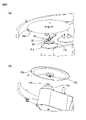
円板状刃物20から取り外した刃物用固定具30を、上板12から円板状刃物20を取り外すために利用することができる。図7に示すように、円板状刃物20の上面側から、刃物用固定具30の連結部31を円板状刃物20の被連結部22に取り付ける。
The
図8(a)~図8(c)を用いて、刃物用固定具30を、円板状刃物20の上面側から取付ける方法について説明する。図8(a)に示すように、中空部23の上端に、連結部31の挿入部32を挿入する。このとき、ピン34が第二案内溝25の入口25aに一致するよう位置合わせする。そして、図8(b)に示すように、刃物用固定具30を下方(図の矢印D方向)に押し込むとともに矢印E方向に回転させ、ピン34を第二案内溝25の折返し部25bまで押し込む。そして、図8(c)に示すように、さらにE方向に回転させ、第二案内溝25の終端25cにピン34を嵌め込んで固定する。このとき、第一バネ35により刃物用固定具30が上方(図の矢印F方向)、すなわち円板状刃物20から離れる方向に付勢される。それにより、ピン34が終端25cに留まり、連結部31が被連結部22に固定される。使用者は、円板状刃物20が取付けられた刃物用固定具30を持ち上げることで、円板状刃物20を上板12から取り出すことができる。使用者は円板状刃物20に直接接触することなく取り外すことができるため、円板状刃物20による怪我を防止することができる。
A method of attaching the
従来の野菜細断装置では、円板状刃物に刃物用固定具を取付ける場合又は取外す場合、円板状刃物が回転しないよう、回り止めピンを円板状刃物に差し込んでいた。本実施形態の野菜細断装置1では、回り止めピンを使用することなく、円板状刃物20の回転をロックするロック機構を備えている。以下では、本実施形態の野菜細断装置1に設けられた円板状刃物20の回転をロックするロック機構2について説明する。
In the conventional vegetable shredding device, when the fixture for a blade is attached to or removed from the disc-shaped blade, a detent pin is inserted into the disc-shaped blade so that the disc-shaped blade does not rotate. The
野菜細断装置1は、図2に示すように、一台の電動モータ40を駆動させることで、電動モータ40のドラム用モータプーリ43に連結された中空軸のドラム用シャフト16及び刃物用モータプーリ44に連結された中空軸の刃物用シャフト17を回転させている。そのため、ドラム用シャフト16の回転をロックすることにより、連結する電動モータ40のドラム用モータプーリ43、刃物用モータプーリ44の回転がロックされ、刃物用シャフト17の回転がロックされる。
As shown in FIG. 2, the
そこで、本実施形態の野菜細断装置1は、図2及び図9に示すように、中空軸であるドラム用シャフト16の中空部に棒状のドラム用固定具47を設け、ドラム用固定具47の下方端部に円錐台のテーパーコーン50(嵌合部)を設けている。また、テーパーコーン50の形状に合わせて設けられた被嵌合部51が、テーパーコーン50を覆うよう設置されている。ドラム用固定具47はドラム用シャフト16内に設けられた第三バネ49により上方に付勢され、それにより、テーパーコーン50が被嵌合部51と接触して摩擦抵抗が発生する。ドラム用固定具47の回転がロックされ、それに伴い、ドラム用固定具47と連動するドラム用シャフト16の回転がロックされる。ドラム用シャフト16のロックにより、電動モータ40を介して連動する刃物用シャフト17もロックされ円板状刃物20の回転がロックされる。
Therefore, in the
ドラム用固定具47の回転のロックは、ドラム用固定具47の上端に回転ドラム11を取付けることにより解除される。回転ドラム11によりドラム用固定具47が押し下げられ、それにより、テーパーコーン50と被嵌合部51との嵌合が解除されドラム用シャフト16が回転可能になる。
The rotation lock of the
このように、回り止めピンを用いることなく、回転ドラム11をドラム用シャフト16から外すことで円板状刃物20の回転をロックすることができる。
In this way, the rotation of the disc-shaped
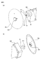
図10~図13に図1に示す野菜細断装置1の別例を示す。図10及び11に示す野菜細断装置1a、1bの円板状刃物20a、20bは、棒状の刃物用固定具30を使わずに、刃物用シャフト17aに直接取付けられる。円板状刃物20a、20bを刃物用シャフト17aに取付ける機構として、図1に示す、連結部31と被連結部22と同様の機構が用いられる。図10に示す野菜細断装置1aでは、刃物用シャフト17aに連結部31aが設けられ、円板状刃物20aには被連結部22aが設けられる。図11に示す野菜細断装置1bでは、刃物用シャフト17bに被連結部22bが設けられ、円板状刃物20bには、連結部31bが設けられる。
10 to 13 show another example of the
図12及び13に示す野菜細断装置1c、1dの円板状刃物20c、20dは、さらに刃物用シャフトを使わずに、電動モータ40の回転軸部41に直接、円板状刃物20c、20dが取付けられる。円板状刃物20c、20dを回転軸部41に取付ける機構として、図1に示す連結部31と被連結部22と同様の機構が用いられる。図12に示す野菜細断装置1cでは、回転軸部41に連結部31cが設けられ、円板状刃物20cに被連結部22cが設けられる。図13に示す野菜細断装置1dでは、回転軸部41に被連結部22dが設けられ、円板状刃物20dに連結部31dが設けられる。また、図12及び図13に示すように、円板状刃物20c、20dの上面に、円板状刃物20c、20dを回転軸部41から取り外す際に用いられるノブ33c、33dが設けられてよい。
The disc-shaped
1、1a、1b、1c、1d 野菜細断装置
10 基台
11 回転ドラム
12 上板
13 飛散防止カバー
14 受枠
15 駆動部
16 ドラム用シャフト
17、17a 刃物用シャフト
18 中空軸カッターホルダ
19 高さ調節ねじ
20、20a、20b、20c、20d 円板状刃物
21 刃物取付板
22、22a、22b、22c、22d 被連結部
30 刃物用固定具
31、31a、31b、31c、31d 連結部
32 挿入部
33、33c、33d ノブ
34 ピン
35 第一バネ
36 第二バネ
37 軸本体
40、40d 電動モータ
41 回転軸部
43 ドラム用モータプーリ
44 刃物用モータプーリ
47 ドラム用固定具
49 第三バネ
50 テーパーコーン(嵌合部)
51 被嵌合部
1, 1a, 1b, 1c, 1d
51 Fitted part
Claims (7)
回転する回転軸部を有する駆動部と、
前記回転軸部に着脱可能に取り付けられ、前記駆動部により回転されることで野菜を細断する円板状刃物と、を備え、
前記駆動部は、前記回転軸部の先端に連結部又は被連結部を備え、
前記円板状刃物は、前記円板状刃物の裏面の中心に、前記駆動部の前記連結部に連結する被連結部、又は、前記駆動部の被連結部に連結する連結部を、備え、
前記被連結部は、前記連結部が挿入される中空部を有するよう筒状に形成されるとともに、前記連結部が挿入される端部から延びて折返し部を有する曲がり形状の第一案内溝が形成され、
前記連結部は、一端に前記被連結部の前記中空部に挿入可能に形成される挿入部と、前記挿入部の外周面から突出して前記第一案内溝を摺動するピンと、他端に前記挿入部が前記被連結部の中空部に挿入されたとき、前記被連結部から離れる方向に前記連結部を付勢する第一弾性部と、を備え、
前記駆動部は、モータと、前記モータにより駆動され前記円板状刃物を回転させる中空軸の刃物用シャフトと、前記刃物用シャフトの中空部を通り、前記円板状刃物を前記刃物用シャフトに固定する回転軸部としての棒状の刃物用固定具と、を備え、
前記円板状刃物は、前記被連結部を備え、前記駆動部の前記刃物用固定具が、前記円板状刃物の被連結部に連結する連結部と、前記刃物用固定具を前記円板状刃物から離れる方向に付勢させる第二弾性部と、を備える、野菜細断装置。 It is a vegetable shredding device that shreds vegetables.
A drive unit having a rotating shaft unit and a rotating shaft unit,
It is provided with a disk-shaped blade that is detachably attached to the rotating shaft portion and is rotated by the driving portion to shred vegetables.
The drive unit is provided with a connecting portion or a connected portion at the tip of the rotating shaft portion.
The disk-shaped blade is provided with a connected portion connected to the connected portion of the drive portion or a connecting portion connected to the connected portion of the drive portion at the center of the back surface of the disk-shaped blade.
The connected portion is formed in a cylindrical shape so as to have a hollow portion into which the connecting portion is inserted, and a curved first guide groove extending from an end into which the connecting portion is inserted and having a folded portion is provided. Formed,
The connecting portion has an insertion portion formed at one end so as to be insertable into the hollow portion of the connected portion, a pin protruding from the outer peripheral surface of the insertion portion and sliding on the first guide groove, and the other end. A first elastic portion that urges the connecting portion in a direction away from the connected portion when the insertion portion is inserted into the hollow portion of the connected portion is provided .
The drive portion passes through a motor, a shaft for a blade of a hollow shaft driven by the motor to rotate the disk-shaped blade, and a hollow portion of the shaft for the blade, and the disk-shaped blade is used as the shaft for the blade. Equipped with a rod-shaped blade fixing tool as a rotating shaft to be fixed,
The disk-shaped blade is provided with the connected portion, and the connecting portion in which the blade fixing tool of the driving unit is connected to the connected portion of the disk-shaped blade and the blade fixing tool are connected to the disk. A vegetable shredding device provided with a second elastic portion that urges the blade away from the blade .
回転する回転軸部を有する駆動部と、
前記回転軸部に着脱可能に取り付けられ、前記駆動部により回転されることで野菜を細断する円板状刃物と、を備え、
前記駆動部は、前記回転軸部の先端に連結部又は被連結部を備え、
前記円板状刃物は、前記円板状刃物の裏面の中心に、前記駆動部の前記連結部に連結する被連結部、又は、前記駆動部の被連結部に連結する連結部を、備え、
前記被連結部は、前記連結部が挿入される中空部を有するよう筒状に形成されるとともに、前記連結部が挿入される端部から延びて折返し部を有する曲がり形状の第一案内溝が形成され、
前記連結部は、一端に前記被連結部の前記中空部に挿入可能に形成される挿入部と、前記挿入部の外周面から突出して前記第一案内溝を摺動するピンと、他端に前記挿入部が前記被連結部の中空部に挿入されたとき、前記被連結部から離れる方向に前記連結部を付勢する第一弾性部と、を備え、
前記駆動部は、モータと、前記モータにより駆動され前記円板状刃物を回転させる回転軸部としての刃物用シャフトと、を備え、
前記円板状刃物が前記連結部を備え、前記刃物用シャフトが前記円板状刃物の前記連結部に連結する前記被連結部を備える、野菜細断装置。 It is a vegetable shredding device that shreds vegetables.
A drive unit having a rotating shaft unit and a rotating shaft unit,
It is provided with a disk-shaped blade that is detachably attached to the rotating shaft portion and is rotated by the driving portion to shred vegetables.
The drive unit is provided with a connecting portion or a connected portion at the tip of the rotating shaft portion.
The disk-shaped blade is provided with a connected portion connected to the connected portion of the drive portion or a connecting portion connected to the connected portion of the drive portion at the center of the back surface of the disk-shaped blade.
The connected portion is formed in a cylindrical shape so as to have a hollow portion into which the connecting portion is inserted, and a curved first guide groove extending from an end into which the connecting portion is inserted and having a folded portion is provided. Formed,
The connecting portion has an insertion portion formed at one end so as to be insertable into the hollow portion of the connected portion, a pin protruding from the outer peripheral surface of the insertion portion and sliding on the first guide groove, and the other end. A first elastic portion that urges the connecting portion in a direction away from the connected portion when the insertion portion is inserted into the hollow portion of the connected portion is provided .
The drive unit includes a motor and a blade blade shaft as a rotation shaft unit that is driven by the motor to rotate the disk-shaped blade.
A vegetable shredding device comprising the connecting portion of the disc-shaped blade and the connected portion in which the blade shaft is connected to the connecting portion of the disk-shaped blade .
回転する回転軸部を有する駆動部と、
前記回転軸部に着脱可能に取り付けられ、前記駆動部により回転されることで野菜を細断する円板状刃物と、を備え、
前記駆動部は、前記回転軸部の先端に連結部又は被連結部を備え、
前記円板状刃物は、前記円板状刃物の裏面の中心に、前記駆動部の前記連結部に連結する被連結部、又は、前記駆動部の被連結部に連結する連結部を、備え、
前記被連結部は、前記連結部が挿入される中空部を有するよう筒状に形成されるとともに、前記連結部が挿入される端部から延びて折返し部を有する曲がり形状の第一案内溝が形成され、
前記連結部は、一端に前記被連結部の前記中空部に挿入可能に形成される挿入部と、前記挿入部の外周面から突出して前記第一案内溝を摺動するピンと、他端に前記挿入部が前記被連結部の中空部に挿入されたとき、前記被連結部から離れる方向に前記連結部を付勢する第一弾性部と、を備え、
前記駆動部は、モータと、前記モータにより駆動され前記円板状刃物を回転させる回転軸部としての刃物用シャフトと、を備え、
前記刃物用シャフトが前記連結部を備え、前記円板状刃物が前記刃物用シャフトの前記連結部に連結する前記被連結部を備える、野菜細断装置。 It is a vegetable shredding device that shreds vegetables.
A drive unit having a rotating shaft unit and a rotating shaft unit,
It is provided with a disk-shaped blade that is detachably attached to the rotating shaft portion and is rotated by the driving portion to shred vegetables.
The drive unit is provided with a connecting portion or a connected portion at the tip of the rotating shaft portion.
The disk-shaped blade is provided with a connected portion connected to the connected portion of the drive portion or a connecting portion connected to the connected portion of the drive portion at the center of the back surface of the disk-shaped blade.
The connected portion is formed in a cylindrical shape so as to have a hollow portion into which the connecting portion is inserted, and a curved first guide groove having a folded portion extending from an end into which the connecting portion is inserted is provided. Formed,
The connecting portion has an insertion portion formed at one end so as to be insertable into the hollow portion of the connected portion, a pin protruding from the outer peripheral surface of the insertion portion and sliding on the first guide groove, and the other end. When the insertion portion is inserted into the hollow portion of the connected portion, the first elastic portion that urges the connecting portion in a direction away from the connected portion is provided .
The drive unit includes a motor and a blade blade shaft as a rotation shaft unit that is driven by the motor to rotate the disk-shaped blade.
A vegetable shredding device comprising the connecting portion of the blade shaft and the connected portion in which the discoid blade is connected to the connecting portion of the blade shaft .
回転する回転軸部を有する駆動部と、
前記回転軸部に着脱可能に取り付けられ、前記駆動部により回転されることで野菜を細断する円板状刃物と、を備え、
前記駆動部は、前記回転軸部の先端に連結部又は被連結部を備え、
前記円板状刃物は、前記円板状刃物の裏面の中心に、前記駆動部の前記連結部に連結する被連結部、又は、前記駆動部の被連結部に連結する連結部を、備え、
前記被連結部は、前記連結部が挿入される中空部を有するよう筒状に形成されるとともに、前記連結部が挿入される端部から延びて折返し部を有する曲がり形状の第一案内溝が形成され、
前記連結部は、一端に前記被連結部の前記中空部に挿入可能に形成される挿入部と、前記挿入部の外周面から突出して前記第一案内溝を摺動するピンと、他端に前記挿入部が前記被連結部の中空部に挿入されたとき、前記被連結部から離れる方向に前記連結部を付勢する第一弾性部と、を備え、
前記駆動部は、前記円板状刃物を直接回転させるモータであり、
前記円板状刃物が前記連結部を備え、前記モータの回転軸部が前記円板状刃物の前記連結部に連結する前記被連結部を備える、野菜細断装置。 It is a vegetable shredding device that shreds vegetables.
A drive unit having a rotating shaft unit and a rotating shaft unit,
It is provided with a disk-shaped blade that is detachably attached to the rotating shaft portion and is rotated by the driving portion to shred vegetables.
The drive unit is provided with a connecting portion or a connected portion at the tip of the rotating shaft portion.
The disk-shaped blade is provided with a connected portion connected to the connected portion of the drive portion or a connecting portion connected to the connected portion of the drive portion at the center of the back surface of the disk-shaped blade.
The connected portion is formed in a cylindrical shape so as to have a hollow portion into which the connecting portion is inserted, and a curved first guide groove extending from an end into which the connecting portion is inserted and having a folded portion is provided. Formed,
The connecting portion has an insertion portion formed at one end so as to be insertable into the hollow portion of the connected portion, a pin protruding from the outer peripheral surface of the insertion portion and sliding on the first guide groove, and the other end. A first elastic portion that urges the connecting portion in a direction away from the connected portion when the insertion portion is inserted into the hollow portion of the connected portion is provided .
The drive unit is a motor that directly rotates the disc-shaped blade.
A vegetable shredding device comprising the connecting portion of the disk-shaped blade and the connected portion in which the rotating shaft portion of the motor is connected to the connecting portion of the disk-shaped blade .
回転する回転軸部を有する駆動部と、
前記回転軸部に着脱可能に取り付けられ、前記駆動部により回転されることで野菜を細断する円板状刃物と、を備え、
前記駆動部は、前記回転軸部の先端に連結部又は被連結部を備え、
前記円板状刃物は、前記円板状刃物の裏面の中心に、前記駆動部の前記連結部に連結する被連結部、又は、前記駆動部の被連結部に連結する連結部を、備え、
前記被連結部は、前記連結部が挿入される中空部を有するよう筒状に形成されるとともに、前記連結部が挿入される端部から延びて折返し部を有する曲がり形状の第一案内溝が形成され、
前記連結部は、一端に前記被連結部の前記中空部に挿入可能に形成される挿入部と、前記挿入部の外周面から突出して前記第一案内溝を摺動するピンと、他端に前記挿入部が前記被連結部の中空部に挿入されたとき、前記被連結部から離れる方向に前記連結部を付勢する第一弾性部と、を備え、
前記駆動部は、前記円板状刃物を直接回転させるモータであり、
前記モータの回転軸部が前記連結部を備え、前記円板状刃物が前記モータの前記連結部に連結する前記被連結部を備える、野菜細断装置。 It is a vegetable shredding device that shreds vegetables.
A drive unit having a rotating shaft unit and a rotating shaft unit,
It is provided with a disk-shaped blade that is detachably attached to the rotating shaft portion and is rotated by the driving portion to shred vegetables.
The drive unit is provided with a connecting portion or a connected portion at the tip of the rotating shaft portion.
The disk-shaped blade is provided with a connected portion connected to the connected portion of the drive portion or a connecting portion connected to the connected portion of the drive portion at the center of the back surface of the disk-shaped blade.
The connected portion is formed in a cylindrical shape so as to have a hollow portion into which the connecting portion is inserted, and a curved first guide groove extending from an end into which the connecting portion is inserted and having a folded portion is provided. Formed,
The connecting portion has an insertion portion formed at one end so as to be insertable into the hollow portion of the connected portion, a pin protruding from the outer peripheral surface of the insertion portion and sliding on the first guide groove, and the other end. A first elastic portion that urges the connecting portion in a direction away from the connected portion when the insertion portion is inserted into the hollow portion of the connected portion is provided .
The drive unit is a motor that directly rotates the disc-shaped blade.
A vegetable shredding device in which a rotary shaft portion of the motor includes the connecting portion, and the disc-shaped blade includes the connected portion in which the connecting portion of the motor is connected .
前記駆動部により駆動され前記回転ドラムを回転させる、中空軸のドラム用シャフトと、
前記ドラム用シャフトの中空部に摺動可能に設けられ、前記回転ドラムを支持し前記ドラム用シャフトとの回転と連動する棒状のドラム用固定具であって、前記ドラム用固定具の下端に設けられた嵌合部と、前記ドラム用固定具を上方に付勢する第三バネとを有する、ドラム用固定具と、
前記回転ドラムが前記ドラム用固定具から取り外された場合に、前記ドラム用固定具が前記第三バネにより上方に移動して前記ドラム用固定具の前記嵌合部が嵌合し、前記ドラム用シャフトの回転が防止される被嵌合部と、備える、請求項1から請求項6の何れか一項に記載の野菜細断装置。 A rotating drum for storing vegetables and
A hollow shaft drum shaft that is driven by the drive unit to rotate the rotary drum,
A rod-shaped drum fixture that is slidably provided in the hollow portion of the drum shaft, supports the rotating drum, and interlocks with rotation with the drum shaft, and is provided at the lower end of the drum fixture. A drum fixture having a fitted fitting and a third spring that urges the drum fixer upward.
When the rotating drum is removed from the drum fixing tool, the drum fixing tool is moved upward by the third spring, and the fitting portion of the drum fixing tool is fitted to the drum fixing tool. The vegetable shredding device according to any one of claims 1 to 6 , comprising a fitted portion for preventing rotation of the shaft.
Priority Applications (1)
| Application Number | Priority Date | Filing Date | Title |
|---|---|---|---|
| JP2018110692A JP7085196B2 (en) | 2018-06-08 | 2018-06-08 | Vegetable shredding device |
Applications Claiming Priority (1)
| Application Number | Priority Date | Filing Date | Title |
|---|---|---|---|
| JP2018110692A JP7085196B2 (en) | 2018-06-08 | 2018-06-08 | Vegetable shredding device |
Publications (2)
| Publication Number | Publication Date |
|---|---|
| JP2019209467A JP2019209467A (en) | 2019-12-12 |
| JP7085196B2 true JP7085196B2 (en) | 2022-06-16 |
Family
ID=68844490
Family Applications (1)
| Application Number | Title | Priority Date | Filing Date |
|---|---|---|---|
| JP2018110692A Active JP7085196B2 (en) | 2018-06-08 | 2018-06-08 | Vegetable shredding device |
Country Status (1)
| Country | Link |
|---|---|
| JP (1) | JP7085196B2 (en) |
Citations (2)
| Publication number | Priority date | Publication date | Assignee | Title |
|---|---|---|---|---|
| JP2006326815A (en) | 2005-05-23 | 2006-12-07 | Happy Kogyo Kk | Chopping device for cabbage and the like |
| US20150183122A1 (en) | 2013-12-31 | 2015-07-02 | Elec-Tech International Co., Ltd. | Cutterhead component for shredding/slicing foods and food processor having the cutterhead component |
Family Cites Families (2)
| Publication number | Priority date | Publication date | Assignee | Title |
|---|---|---|---|---|
| JP3650521B2 (en) * | 1998-02-26 | 2005-05-18 | 東芝テック株式会社 | Cooking device |
| JP3649895B2 (en) * | 1998-02-27 | 2005-05-18 | 東芝テック株式会社 | Cutting body and cooker |
-
2018
- 2018-06-08 JP JP2018110692A patent/JP7085196B2/en active Active
Patent Citations (2)
| Publication number | Priority date | Publication date | Assignee | Title |
|---|---|---|---|---|
| JP2006326815A (en) | 2005-05-23 | 2006-12-07 | Happy Kogyo Kk | Chopping device for cabbage and the like |
| US20150183122A1 (en) | 2013-12-31 | 2015-07-02 | Elec-Tech International Co., Ltd. | Cutterhead component for shredding/slicing foods and food processor having the cutterhead component |
Also Published As
| Publication number | Publication date |
|---|---|
| JP2019209467A (en) | 2019-12-12 |
Similar Documents
| Publication | Publication Date | Title |
|---|---|---|
| US8491356B2 (en) | Adjustable knife sharpener | |
| BRPI0608742A2 (en) | knife blade sharpening machine | |
| US11267146B2 (en) | Cutter head and hair-cutting machine therefor | |
| US7204440B2 (en) | Slicing condiment grinder | |
| KR101777140B1 (en) | Grinder for nipper for nail care | |
| JP7085196B2 (en) | Vegetable shredding device | |
| US6520436B1 (en) | Kitchen grater | |
| KR100946569B1 (en) | Root Vegetable Incision Machine | |
| KR102090187B1 (en) | Cutting machine for garlic | |
| KR102260823B1 (en) | Coffee grinding machine | |
| JP4493043B2 (en) | Flatness adjustment device for vegetable cutting machine | |
| CN220389586U (en) | A cooking cup assembly for dicing | |
| CN110948582A (en) | Bench circular sawing machine for woodwork | |
| JP7085197B2 (en) | Vegetable shredding device | |
| FR2507882A1 (en) | ROTARY FOOD PROCESSING INSTRUMENT FOR KITCHEN ROBOT APPLIANCES | |
| US1939847A (en) | Electrically operated potato parer | |
| JP2002239983A (en) | Leek cutting equipment | |
| JPH0121753Y2 (en) | ||
| US20060118668A1 (en) | Vegetable cutting device | |
| JP4305877B2 (en) | Drill blade grinder | |
| FR2507952A1 (en) | Cutter for shattered bevelled edge on natural slate - uses rotary disc with peripheral projections to provide hammer effect | |
| US761077A (en) | Apparatus for cutting and beveling sheets of cardboard or the like. | |
| US798584A (en) | Vegetable-cutter. | |
| US1197794A (en) | Cloth-cutting machine. | |
| KR960009529Y1 (en) | cutter |
Legal Events
| Date | Code | Title | Description |
|---|---|---|---|
| A621 | Written request for application examination |
Free format text: JAPANESE INTERMEDIATE CODE: A621 Effective date: 20210407 |
|
| A977 | Report on retrieval |
Free format text: JAPANESE INTERMEDIATE CODE: A971007 Effective date: 20220222 |
|
| A131 | Notification of reasons for refusal |
Free format text: JAPANESE INTERMEDIATE CODE: A131 Effective date: 20220308 |
|
| A521 | Request for written amendment filed |
Free format text: JAPANESE INTERMEDIATE CODE: A523 Effective date: 20220420 |
|
| TRDD | Decision of grant or rejection written | ||
| A01 | Written decision to grant a patent or to grant a registration (utility model) |
Free format text: JAPANESE INTERMEDIATE CODE: A01 Effective date: 20220510 |
|
| A61 | First payment of annual fees (during grant procedure) |
Free format text: JAPANESE INTERMEDIATE CODE: A61 Effective date: 20220530 |
|
| R150 | Certificate of patent or registration of utility model |
Ref document number: 7085196 Country of ref document: JP Free format text: JAPANESE INTERMEDIATE CODE: R150 |
|
| R250 | Receipt of annual fees |
Free format text: JAPANESE INTERMEDIATE CODE: R250 |