JP7079955B2 - Temperature characterization method - Google Patents
Temperature characterization method Download PDFInfo
- Publication number
- JP7079955B2 JP7079955B2 JP2017255089A JP2017255089A JP7079955B2 JP 7079955 B2 JP7079955 B2 JP 7079955B2 JP 2017255089 A JP2017255089 A JP 2017255089A JP 2017255089 A JP2017255089 A JP 2017255089A JP 7079955 B2 JP7079955 B2 JP 7079955B2
- Authority
- JP
- Japan
- Prior art keywords
- temperature
- difference
- temperature data
- internal
- internal space
- Prior art date
- Legal status (The legal status is an assumption and is not a legal conclusion. Google has not performed a legal analysis and makes no representation as to the accuracy of the status listed.)
- Active
Links
Images


Classifications
-
- F—MECHANICAL ENGINEERING; LIGHTING; HEATING; WEAPONS; BLASTING
- F24—HEATING; RANGES; VENTILATING
- F24F—AIR-CONDITIONING; AIR-HUMIDIFICATION; VENTILATION; USE OF AIR CURRENTS FOR SCREENING
- F24F11/00—Control or safety arrangements
- F24F11/30—Control or safety arrangements for purposes related to the operation of the system, e.g. for safety or monitoring
-
- F—MECHANICAL ENGINEERING; LIGHTING; HEATING; WEAPONS; BLASTING
- F24—HEATING; RANGES; VENTILATING
- F24F—AIR-CONDITIONING; AIR-HUMIDIFICATION; VENTILATION; USE OF AIR CURRENTS FOR SCREENING
- F24F11/00—Control or safety arrangements
- F24F11/62—Control or safety arrangements characterised by the type of control or by internal processing, e.g. using fuzzy logic, adaptive control or estimation of values
- F24F11/63—Electronic processing
-
- G—PHYSICS
- G01—MEASURING; TESTING
- G01N—INVESTIGATING OR ANALYSING MATERIALS BY DETERMINING THEIR CHEMICAL OR PHYSICAL PROPERTIES
- G01N17/00—Investigating resistance of materials to the weather, to corrosion, or to light
-
- G—PHYSICS
- G01—MEASURING; TESTING
- G01N—INVESTIGATING OR ANALYSING MATERIALS BY DETERMINING THEIR CHEMICAL OR PHYSICAL PROPERTIES
- G01N17/00—Investigating resistance of materials to the weather, to corrosion, or to light
- G01N17/002—Test chambers
-
- G—PHYSICS
- G01—MEASURING; TESTING
- G01N—INVESTIGATING OR ANALYSING MATERIALS BY DETERMINING THEIR CHEMICAL OR PHYSICAL PROPERTIES
- G01N17/00—Investigating resistance of materials to the weather, to corrosion, or to light
- G01N17/02—Electrochemical measuring systems for weathering, corrosion or corrosion-protection measurement
-
- G—PHYSICS
- G06—COMPUTING; CALCULATING OR COUNTING
- G06F—ELECTRIC DIGITAL DATA PROCESSING
- G06F17/00—Digital computing or data processing equipment or methods, specially adapted for specific functions
- G06F17/10—Complex mathematical operations
- G06F17/11—Complex mathematical operations for solving equations, e.g. nonlinear equations, general mathematical optimization problems
-
- F—MECHANICAL ENGINEERING; LIGHTING; HEATING; WEAPONS; BLASTING
- F24—HEATING; RANGES; VENTILATING
- F24F—AIR-CONDITIONING; AIR-HUMIDIFICATION; VENTILATION; USE OF AIR CURRENTS FOR SCREENING
- F24F2110/00—Control inputs relating to air properties
- F24F2110/10—Temperature
Landscapes
- Engineering & Computer Science (AREA)
- Physics & Mathematics (AREA)
- Chemical & Material Sciences (AREA)
- General Engineering & Computer Science (AREA)
- Mathematical Physics (AREA)
- General Physics & Mathematics (AREA)
- Mechanical Engineering (AREA)
- Combustion & Propulsion (AREA)
- Life Sciences & Earth Sciences (AREA)
- Signal Processing (AREA)
- Fuzzy Systems (AREA)
- Analytical Chemistry (AREA)
- Immunology (AREA)
- Pathology (AREA)
- General Health & Medical Sciences (AREA)
- Biochemistry (AREA)
- Health & Medical Sciences (AREA)
- Environmental Sciences (AREA)
- Environmental & Geological Engineering (AREA)
- Ecology (AREA)
- Biodiversity & Conservation Biology (AREA)
- Mathematical Analysis (AREA)
- Computational Mathematics (AREA)
- Mathematical Optimization (AREA)
- Pure & Applied Mathematics (AREA)
- Data Mining & Analysis (AREA)
- Theoretical Computer Science (AREA)
- Operations Research (AREA)
- Algebra (AREA)
- Databases & Information Systems (AREA)
- Software Systems (AREA)
- Air Conditioning Control Device (AREA)
- Testing Resistance To Weather, Investigating Materials By Mechanical Methods (AREA)
- Investigating Or Analyzing Materials Using Thermal Means (AREA)
Description
本発明は、環境試験装置の内部空間の温度特性を評価する温度特性評価方法に関する。 The present invention relates to a temperature characteristic evaluation method for evaluating the temperature characteristics of the internal space of an environmental test apparatus.
医薬品の安定性を評価するための安定性試験として、医薬品を一定の温度および湿度で長期間保存する環境試験が行われる。医薬品の環境試験には、環境試験装置の1つとして恒温恒湿槽が用いられる(例えば特許文献1および2参照)。恒温恒湿槽は、試験室、加湿部、冷却部、加熱部および送風部を備える。加湿部、冷却部、加熱部および送風部により試験室内の温度および湿度が一定に保たれた試験室内で医薬品が規定された期間保存される。 As a stability test for evaluating the stability of a drug, an environmental test is conducted in which the drug is stored at a constant temperature and humidity for a long period of time. A constant temperature and humidity chamber is used as one of the environmental test devices for the environmental test of pharmaceutical products (see, for example, Patent Documents 1 and 2). The constant temperature and humidity chamber includes a test room, a humidifying section, a cooling section, a heating section, and a blowing section. The drug is stored for a specified period in the test room where the temperature and humidity in the test room are kept constant by the humidifying part, the cooling part, the heating part and the blowing part.
医薬品の環境試験では、恒温恒湿槽の試験室内の温度および湿度が保存期間中に所定の範囲内に保たれていることを保証する必要がある。そこで、一般的には、恒温恒湿槽の試験室内の所定の位置での温度および湿度が常時モニタリングセンサまたは制御センサにより測定される。また、一定期間(例えば1年)ごとに恒温恒湿槽の試験室内の温度および湿度の分布が測定される。それにより、保存期間中に試験室内の温度および湿度が所定の範囲内に保たれていることが保証される。この場合、環境試験が規定された条件で行われたことを示す文書が証拠として関係機関に提出される。 In environmental testing of pharmaceutical products, it is necessary to ensure that the temperature and humidity in the test chamber of the constant temperature and humidity chamber are kept within a predetermined range during the storage period. Therefore, in general, the temperature and humidity at a predetermined position in the test chamber of the constant temperature and humidity chamber are constantly measured by a monitoring sensor or a control sensor. In addition, the distribution of temperature and humidity in the test chamber of the constant temperature and humidity chamber is measured at regular intervals (for example, one year). This ensures that the temperature and humidity in the test room are kept within the specified range during the storage period. In this case, a document showing that the environmental test was conducted under the specified conditions will be submitted to the relevant organizations as evidence.
しかしながら、試験室内の温度は外気の温度の影響により変化する可能性がある。上記の方法では、温度の分布の測定時点と測定時点との間の期間において、試験室内のモニタリングセンサまたは制御センサが配置された位置以外の位置の温度が所定の範囲内に維持されたか否かを判定することができない。一方、モニタリングセンサまたは制御センサとは別個に温度センサを用いて試験室内の温度を常時監視すると、温度センサ等の部品コストおよび作業コストが高くなる。そこで、低コストでかつ外気の温度を考慮して内部空間の温度特性を評価する方法が望まれる。 However, the temperature in the test chamber may change due to the influence of the temperature of the outside air. In the above method, whether or not the temperature at a position other than the position where the monitoring sensor or the control sensor in the test chamber is placed is maintained within a predetermined range during the period between the measurement time and the measurement time of the temperature distribution. Cannot be determined. On the other hand, if the temperature in the test room is constantly monitored by using a temperature sensor separately from the monitoring sensor or the control sensor, the cost of parts such as the temperature sensor and the work cost increase. Therefore, a method for evaluating the temperature characteristics of the internal space at low cost and in consideration of the temperature of the outside air is desired.
本発明の目的は、低コストかつ高い信頼性で環境試験装置の内部空間の温度特性を評価することが可能な温度特性評価方法を提供することである。 An object of the present invention is to provide a temperature characteristic evaluation method capable of evaluating the temperature characteristics of the internal space of an environmental test apparatus at low cost and with high reliability.
(1)本発明に係る温度特性評価方法は、内部空間を有するとともに内部空間の温度を予め定められた設定温度に維持するように動作する環境試験装置について内部空間の温度特性を評価する温度特性評価方法であって、環境試験装置の設定温度を設定温度データとして取得し、環境試験装置が設置された空間の温度である周囲温度を測定することにより周囲温度データを取得するとともに、内部空間の内部温度を測定することにより内部温度データを取得するステップと、設定温度および周囲温度のうち少なくとも一方を変更して設定温度データ、周囲温度データおよび内部温度データを取得することにより、設定温度データと周囲温度データと内部温度データとの複数の組み合わせを複数の温度データ群として得るステップと、複数の温度データ群の各々について、周囲温度データと設定温度データとの差分を第1の差分として算出し、内部温度データと設定温度データとの差分を第2の差分として算出し、算出された第1および第2の差分の組み合わせを差分群として得るステップと、複数の温度データ群についての複数の差分群を一次関数で近似し、一次関数を性能関数として得るステップと、性能関数を用いて環境試験装置の内部空間の温度特性に関する評価を行うステップとを含む。 (1) The temperature characteristic evaluation method according to the present invention is a temperature characteristic that evaluates the temperature characteristic of the internal space of an environmental test apparatus that has an internal space and operates so as to maintain the temperature of the internal space at a predetermined set temperature. In the evaluation method, the set temperature of the environmental test equipment is acquired as the set temperature data, and the ambient temperature data, which is the temperature of the space where the environmental test equipment is installed, is acquired to acquire the ambient temperature data and the internal space. The step of acquiring the internal temperature data by measuring the internal temperature, and the set temperature data by changing at least one of the set temperature and the ambient temperature to acquire the set temperature data, the ambient temperature data, and the internal temperature data. The step of obtaining a plurality of combinations of the ambient temperature data and the internal temperature data as a plurality of temperature data groups, and the difference between the ambient temperature data and the set temperature data for each of the plurality of temperature data groups are calculated as the first difference. , The step of calculating the difference between the internal temperature data and the set temperature data as the second difference and obtaining the combination of the calculated first and second differences as the difference group, and the plurality of differences for the plurality of temperature data groups. It includes a step of approximating a group with a linear function and obtaining the linear function as a performance function, and a step of evaluating the temperature characteristics of the internal space of the environmental test apparatus using the performance function.
ここで、温度特性とは、例えば、周囲温度の変化が内部温度に与える影響度、または周囲温度の変化が第2の差分の余裕度(後述する)に与える影響度をいう。 Here, the temperature characteristic means, for example, the degree of influence that a change in ambient temperature has on the internal temperature, or the degree of influence that a change in ambient temperature has on a second difference margin (described later).
この温度特性評価方法によれば、環境試験装置の周囲温度と設定温度との差を表す第1の差分および環境試験装置の内部温度と設定温度と差を表す第2の差分が取得され、第1の差分と第2の差分との関係を表す性能関数が得られる。性能関数は、周囲温度が内部温度と設定温度との差に与える影響を表している。この性能関数における第1の差分は、設定温度および周囲温度のうち少なくとも一方を変更することにより得られるため、周囲温度を大きく変化させることなく広い範囲で第1の差分の複数の値を得ることができる。そのため、性能関数を高い精度で得ることができる。このような性能関数を用いることにより、任意の時点の内部温度を高い精度で評価することが可能となる。また、したがって、低コストでかつ高い信頼性で環境試験装置の内部空間の温度特性を評価することが可能となる。 According to this temperature characteristic evaluation method, the first difference representing the difference between the ambient temperature of the environmental test device and the set temperature and the second difference representing the difference between the internal temperature of the environmental test device and the set temperature are acquired, and the second difference is obtained. A performance function representing the relationship between the difference of 1 and the difference of the second is obtained. The performance function represents the effect of ambient temperature on the difference between the internal temperature and the set temperature. Since the first difference in this performance function is obtained by changing at least one of the set temperature and the ambient temperature, a plurality of values of the first difference can be obtained in a wide range without significantly changing the ambient temperature. Can be done. Therefore, the performance function can be obtained with high accuracy. By using such a performance function, it is possible to evaluate the internal temperature at an arbitrary time point with high accuracy. Therefore, it is possible to evaluate the temperature characteristics of the internal space of the environmental test apparatus at low cost and with high reliability.
(2)温度特性評価方法は、性能関数の傾き係数を求めるステップをさらに含み、評価を行うステップは、性能関数の傾き係数について許容係数範囲を設定するステップと、性能関数の傾き係数が許容係数範囲内にあるか否かを判定するステップとを含んでもよい。 (2) The temperature characteristic evaluation method further includes a step of obtaining the slope coefficient of the performance function, and the evaluation step includes a step of setting an allowable coefficient range for the slope coefficient of the performance function and a step of setting the slope coefficient of the performance function as the allowable coefficient. It may include a step of determining whether or not it is within the range.
この場合、性能関数の傾き係数が許容係数範囲内にあるか否かに基づいて周囲温度の変動による内部温度と設定温度との差の変動が許容範囲内にあるか否かを判定することができる。これにより、環境試験装置における内部空間の温度特性に関する性能を評価することが可能となる。 In this case, it is possible to determine whether or not the fluctuation of the difference between the internal temperature and the set temperature due to the fluctuation of the ambient temperature is within the allowable range based on whether or not the slope coefficient of the performance function is within the allowable coefficient range. can. This makes it possible to evaluate the performance regarding the temperature characteristics of the internal space in the environmental test device.
(3)温度特性評価方法は、3以上の複数の差分群および性能関数に基づいて性能関数の決定係数を算出するステップをさらに含んでもよい。 (3) The temperature characteristic evaluation method may further include a step of calculating the coefficient of determination of the performance function based on a plurality of difference groups of 3 or more and the performance function.
この場合、決定係数に基づいて性能関数を用いて内部空間の温度特性が評価できるか否かを判断することができる。 In this case, it is possible to determine whether or not the temperature characteristics of the internal space can be evaluated using the performance function based on the coefficient of determination.
(4)評価を行うステップは、第2の差分についての許容範囲を第2の差分許容範囲として設定するステップと、第2の差分を取得するステップと、第2の差分許容範囲の上限値または下限値に対する第2の差分の余裕度を算出するステップとを含んでもよい。 (4) The steps for evaluation include a step of setting the allowable range for the second difference as the second difference allowable range, a step of acquiring the second difference, and an upper limit value or the upper limit value of the second difference allowable range. It may include a step of calculating the margin of the second difference with respect to the lower limit value.
この場合、内部温度と設定温度との差が第2の差分許容範囲の上限値または下限値に対してどの程度の余裕度を有するかを判定することができる。それにより、任意の時点において内部温度と設定温度との差が第2の差分許容範囲内にあるか否かを推定することが可能となる。 In this case, it is possible to determine how much margin the difference between the internal temperature and the set temperature has with respect to the upper limit value or the lower limit value of the second difference tolerance range. Thereby, it becomes possible to estimate whether or not the difference between the internal temperature and the set temperature is within the second allowable difference range at an arbitrary time point.
(5)第2の差分を取得するステップは、性能関数が得られた後の第1の時点における周囲温度を測定することにより周囲温度データを得るとともに設定温度データを取得するステップと、第1の時点で得られた周囲温度データおよび取得された設定温度データに基づいて第1の時点における第1の差分を算出するステップと、第1の時点における第1の差分および性能関数に基づいて第1の時点における第2の差分を算出するステップとを含んでもよい。 (5) The step of acquiring the second difference is the step of acquiring the ambient temperature data and the set temperature data by measuring the ambient temperature at the first time point after the performance function is obtained, and the first step. The step of calculating the first difference at the first time point based on the ambient temperature data obtained at the time point and the acquired set temperature data, and the first difference and the performance function at the first time point. It may include a step of calculating the second difference at the time point 1.
この場合、第1の時点で周囲温度を測定することによりその第1の時点での第2の差分を算出することができる。それにより、内部温度を測定することなく第1の時点で内部空間の温度特性を評価することができる。 In this case, the second difference at the first time point can be calculated by measuring the ambient temperature at the first time point. Thereby, the temperature characteristic of the internal space can be evaluated at the first time point without measuring the internal temperature.
(6)第2の差分許容範囲の上限値および下限値を性能関数の第2の差分に代入することにより、第1の差分についての許容範囲である第1の差分許容範囲の上限値および下限値を算出するステップと、第1の差分許容範囲の上限値および下限値と設定温度データとに基づいて周囲温度データの許容範囲の上限値および下限値を算出するステップとをさらに含んでもよい。 (6) By substituting the upper limit value and the lower limit value of the second difference tolerance range into the second difference of the performance function, the upper limit value and the lower limit value of the first difference tolerance range which is the tolerance range for the first difference. A step of calculating the value and a step of calculating the upper limit value and the lower limit value of the allowable range of the ambient temperature data based on the upper limit value and the lower limit value of the first difference allowable range and the set temperature data may be further included.
この場合、第2の差分が第2の差分許容範囲内にあるために要求される周囲温度の許容範囲の上限値および下限値を判定することができる。それにより、周囲温度を許容範囲内に調整することにより内部温度と設定温度との差を第2の差分許容範囲内に維持することが可能となる。 In this case, it is possible to determine the upper limit value and the lower limit value of the allowable range of the ambient temperature required because the second difference is within the second allowable range. Thereby, by adjusting the ambient temperature within the allowable range, the difference between the internal temperature and the set temperature can be maintained within the second allowable difference range.
(7)内部温度データを取得するステップは、内部空間内の複数の位置の各々における内部温度を測定することにより複数の内部温度データを取得するステップを含み、複数の温度データ群を得るステップは、複数の位置の各々についての複数の温度データ群を得るステップを含み、差分群を得るステップは、複数の位置の各々についての差分群を得るステップを含み、性能関数を得るステップは、複数の位置の各々についての性能関数を得るステップを含み、評価を行うステップは、複数の位置の各々についての性能関数に基づいて、内部空間の各位置での温度特性を評価するステップを含んでもよい。 (7) The step of acquiring the internal temperature data includes the step of acquiring a plurality of internal temperature data by measuring the internal temperature at each of the plurality of positions in the internal space, and the step of acquiring a plurality of temperature data groups is , A step of obtaining a plurality of temperature data groups for each of a plurality of positions, a step of obtaining a difference group includes a step of obtaining a difference group for each of a plurality of positions, and a step of obtaining a performance function is a plurality of steps. The step of obtaining and evaluating the performance function for each of the positions may include the step of evaluating the temperature characteristics at each position in the internal space based on the performance function for each of the plurality of positions.
この場合、環境試験装置の内部空間内の複数の位置についての性能関数に基づいて各位置での内部空間の温度特性を評価することが可能となる。 In this case, it is possible to evaluate the temperature characteristics of the internal space at each position based on the performance functions for a plurality of positions in the internal space of the environmental test apparatus.
(8)評価を行うステップは、複数の位置についての複数の性能関数に基づいて、複数の位置のうち最も低い温度特性を有する位置を判定するステップをさらに含んでもよい。 (8) The step of performing the evaluation may further include a step of determining the position having the lowest temperature characteristic among the plurality of positions based on a plurality of performance functions for the plurality of positions.
この場合、環境試験装置の内部空間内で最も低い温度特性を有する位置における内部温度を監視することにより、内部空間の他の位置における温度特性を評価することができる。 In this case, by monitoring the internal temperature at the position having the lowest temperature characteristic in the internal space of the environmental test apparatus, the temperature characteristic at another position in the internal space can be evaluated.
(9)評価を行うステップは、性能関数が得られた後の第2の時点における複数の位置について第2の差分を取得するステップと、複数の位置についての第2の差分に基づいて、複数の位置での内部空間の温度特性を評価するステップとを含んでもよい。 (9) A plurality of evaluation steps are performed based on a step of acquiring a second difference for a plurality of positions at a second time point after the performance function is obtained and a second difference for a plurality of positions. It may include a step of evaluating the temperature characteristics of the internal space at the position of.
この場合、第2の時点での内部空間の複数の位置における温度特性を評価することが可能となる。 In this case, it is possible to evaluate the temperature characteristics at a plurality of positions in the internal space at the second time point.
(10)内部温度データを取得するステップは、内部空間内の複数の位置の各々における内部温度を測定することにより複数の内部温度データを取得するステップを含み、複数の温度データ群を得るステップは、複数の位置の各々についての複数の温度データ群を得るステップを含み、差分群を得るステップは、複数の位置の各々についての差分群を得るステップを含み、性能関数を得るステップは、複数の位置の各々についての性能関数を得るステップを含み、評価を行うステップは、第2の差分についての許容範囲を第2の差分許容範囲として設定するステップと、性能関数が得られた後の第2の時点における複数の位置について第2の差分を取得するステップと、複数の位置について第2の差分許容範囲の上限値または下限値に対する第2の差分の余裕度を算出するステップと、複数の位置についての第2の差分値の余裕度のうち最大値または最小値である余裕度を有する位置を特定するステップとを含んでもよい。 (10) The step of acquiring the internal temperature data includes the step of acquiring a plurality of internal temperature data by measuring the internal temperature at each of the plurality of positions in the internal space, and the step of acquiring a plurality of temperature data groups is , A step of obtaining a plurality of temperature data groups for each of a plurality of positions, a step of obtaining a difference group includes a step of obtaining a difference group for each of a plurality of positions, and a step of obtaining a performance function is a plurality of steps. The steps of obtaining the performance function for each of the positions and performing the evaluation include a step of setting the tolerance for the second difference as the second difference tolerance and a second step after the performance function is obtained. A step of acquiring a second difference for a plurality of positions at the time point of It may include a step of specifying a position having a margin which is the maximum value or the minimum value among the margins of the second difference value of the above.
この場合、環境試験装置の内部空間内で最も低い温度特性を有する位置または最も高い温度特性を有する位置を特定することができる。 In this case, the position having the lowest temperature characteristic or the position having the highest temperature characteristic can be specified in the internal space of the environmental test apparatus.
(11)第2の時点における第2の差分を取得するステップは、第2の時点における周囲温度を測定することにより周囲温度データを取得するとともに設定温度データを取得するステップと、第2の時点で取得された周囲温度データおよび取得された設定温度データに基づいて第2の時点における第1の差分を算出するステップと、第2の時点における第1の差分および性能関数に基づいて第2の時点における第2の差分を算出するステップとを含んでもよい。 (11) The steps for acquiring the second difference at the second time point are the step of acquiring the ambient temperature data and the set temperature data by measuring the ambient temperature at the second time point, and the second time point. The step of calculating the first difference at the second time point based on the ambient temperature data and the set temperature data obtained in, and the second difference based on the first difference and the performance function at the second time point. It may include a step of calculating a second difference at a time point.
この場合、第2の時点における周囲温度を測定することにより内部温度と設定温度との差を算出することができる。したがって、内部温度を測定するための温度計を内部空間に配置する必要がないので、作業コストおよび部品コストが低減される。 In this case, the difference between the internal temperature and the set temperature can be calculated by measuring the ambient temperature at the second time point. Therefore, since it is not necessary to arrange a thermometer for measuring the internal temperature in the internal space, the work cost and the component cost are reduced.
(12)環境試験装置は外壁面を有し、周囲温度は、環境試験装置の外壁面の温度であってもよい。この場合、内部温度に影響を与えやすい位置の温度が周囲温度として得られる。それにより、温度特性の評価の精度が向上する。また、周囲温度の測定を容易に行うことができる。 (12) The environmental test apparatus has an outer wall surface, and the ambient temperature may be the temperature of the outer wall surface of the environmental test apparatus. In this case, the temperature at a position that easily affects the internal temperature is obtained as the ambient temperature. As a result, the accuracy of evaluation of temperature characteristics is improved. In addition, the ambient temperature can be easily measured.
(13)内部温度は、内部空間の隅部の温度であってもよい。この場合、試験体を置くスペースを確保しつつ内部温度を測定することが可能となる。 (13) The internal temperature may be the temperature at the corner of the internal space. In this case, it is possible to measure the internal temperature while securing a space for placing the test piece.
(14)環境試験装置は、空気調和部を含み、空気調和部により調和された空気を内部空間内へ吹き出す吹出し口と内部空間の空気を空気調和部へ吸い込む吸込み口とを有し、設定温度は、吹出し口または吸込み口の空気の温度であってもよい。 (14) The environmental test apparatus includes an air-conditioned unit, has an outlet for blowing out air conditioned by the air-conditioned unit into the internal space, and a suction port for sucking air in the internal space into the air-conditioned unit, and has a set temperature. May be the temperature of the air at the outlet or inlet.
(15)複数の温度データ群を得るステップは、設定温度および周囲温度を変更しないで周囲温度および内部温度を異なる複数の時点で複数回ずつ測定することにより複数のデータ群を得るステップを含んでもよい。 (15) The step of obtaining a plurality of temperature data groups may include a step of obtaining a plurality of data groups by measuring the ambient temperature and the internal temperature multiple times at different time points without changing the set temperature and the ambient temperature. good.
この場合、ノイズ等による周囲温度データおよび内部温度データの変動の影響を低減することができる。 In this case, it is possible to reduce the influence of fluctuations in the ambient temperature data and the internal temperature data due to noise and the like.
本発明によれば、低コストでかつ高い信頼性で環境試験装置の内部空間の温度特性を評価することが可能となる。 According to the present invention, it is possible to evaluate the temperature characteristics of the internal space of the environmental test apparatus at low cost and with high reliability.
以下、本発明の実施の形態に係る温度特性評価方法について図面を参照しながら詳細に説明する。 Hereinafter, the temperature characteristic evaluation method according to the embodiment of the present invention will be described in detail with reference to the drawings.
(1)恒温恒湿槽の構成
図1(a)は本実施の形態に係る温度特性評価方法に用いられる恒温恒湿槽の斜視図、図1(b)は図1(a)の恒温恒湿槽の扉が開かれた状態を示す斜視図である。図2は図1の恒温恒湿槽の垂直断面図である。図1および図2の恒温恒湿槽1は、例えば医薬品の安定性試験のための環境試験に使用される環境試験装置である。
(1) Configuration of constant temperature and humidity chamber FIG. 1 (a) is a perspective view of the constant temperature and humidity chamber used in the temperature characteristic evaluation method according to the present embodiment, and FIG. 1 (b) is a constant temperature and constant temperature of FIG. 1 (a). It is a perspective view which shows the state which the door of a wet tank is opened. FIG. 2 is a vertical cross-sectional view of the constant temperature and humidity chamber of FIG. The constant temperature and humidity chamber 1 of FIGS. 1 and 2 is an environmental test apparatus used for an environmental test for, for example, a stability test of a drug.
図1および図2に示すように、恒温恒湿槽1は、直方体形状の上部筐体2および直方体形状の下部筐体3を備える。上部筐体2は、前部開口を有する。上部筐体2の前部開口には、扉20が開閉可能に設けられている。扉20には、操作盤21および表示器22が取り付けられている。
As shown in FIGS. 1 and 2, the constant temperature and humidity chamber 1 includes a rectangular parallelepiped
図2に示すように、上部筐体2内には、隔壁4が設けられている。隔壁4は、上部筐体2内の閉空間を試験室である内部空間ISと空気調和空間(以下、空調空間と呼ぶ。)5とに区画している。内部空間ISには、1または複数の棚板23が取り付けられている。棚板23上に医薬品等の試験体24が載置される。
As shown in FIG. 2, a
隔壁4の上部には吹出し口41が設けられ、隔壁4の下部には吸込み口42が設けられている。吹出し口41の近傍には、温湿度センサSE0が取り付けられている。なお、温湿度センサSE0が吸込み口42の近傍に取り付けられてもよい。
An
空調空間5には、空気調和部として、加湿部51、冷却・除湿部52、加熱部53および送風部54が配置されている。加湿部51は、水が貯留されるパン51aおよびシーズヒータ51bを含む。冷却・除湿部52は、例えば冷却器を含む。加熱部53は、例えばワイヤストリップヒータを含む。送風部54は、例えばシロッコファンを含む。上部筐体2および下部筐体3の背面側には排気通路6が設けられている。
In the
下部筐体3の前面には、空気導入口31が設けられている。下部筐体3内には、圧縮器32、冷却ファン33および凝縮器34が配置されている。凝縮器34は冷媒配管35を介して冷却・除湿部52に接続されている。冷媒配管35には、電磁開閉弁38および膨張弁39が設けられている。冷却・除湿部52は冷媒配管36を介して圧縮器32と接続され、圧縮器32は冷媒配管37を介して凝縮器34と接続されている。
An
冷却・除湿部52から導出された冷媒は、冷媒配管36を通して圧縮器32に導入され、圧縮器32により圧縮される。圧縮された冷媒は、冷媒配管37を通して凝縮器34に導かれ、凝縮器34により凝縮される。凝縮された冷媒は、冷媒配管35および電磁開閉弁38を通して膨張弁39に導かれ、膨張弁39により膨張される。膨張された冷媒は冷却・除湿部52に導入される。加湿部51は、空調空間5内の空気を加湿する。冷却・除湿部52は、加湿された空気を冷媒の蒸発熱により冷却および除湿する。加熱部53は、冷却および除湿された空気を加熱する。空調空間5において温度および湿度が調整された空気は、白抜きの矢印で示されるように、送風部54により吹出し口41を通して内部空間IS内へ吹き出され、内部空間IS内の空気は吸込み口42を通して空調空間5内に吸い込まれる。
The refrigerant derived from the cooling /
また、冷却ファン33により空気導入口31を通して下部筐体3内に空気が導入される。それにより、凝縮器34が冷却される。下部筐体3内の空気は、ハッチングが付された矢印で示されるように、排気通路6を通して背面部の排気口61から排出される。
Further, air is introduced into the
また、図1(a),(b)に示すように、下部筐体3内にはコントローラ7が設けられている。コントローラ7は、温湿度センサSE0の測定値に基づいて加湿部51、冷却・除湿部52、加熱部53および送風部54を制御する。それにより、内部空間IS内の温度および湿度がそれぞれ設定温度および設定湿度に維持される。コントローラ7には、操作盤21および表示器22が接続されている。
Further, as shown in FIGS. 1 (a) and 1 (b), a
(2)性能関数の算出方法
次に、本実施の形態に係る温度特性評価方法に用いられる性能関数の算出方法について説明する。性能関数の算出は、恒温恒湿槽1の出荷前に工場で行われてもよく、医薬品の製造会社または研究機関への恒温恒湿槽1の納入後に行われてもよい。性能関数の算出が恒温恒湿槽1の納入後に行われる場合には、内部空間IS内に試験体24が置かれない状態または試験体24が置かれた状態で性能関数が算出される。
(2) Calculation method of performance function Next, a calculation method of the performance function used in the temperature characteristic evaluation method according to the present embodiment will be described. The calculation of the performance function may be performed at the factory before the constant temperature and humidity chamber 1 is shipped, or may be performed after the delivery of the constant temperature and humidity chamber 1 to the pharmaceutical manufacturing company or the research institute. When the performance function is calculated after the delivery of the constant temperature and humidity chamber 1, the performance function is calculated in a state where the
図1の恒温恒湿槽1は、建屋の部屋内に設置される。恒温恒湿槽1の内部空間ISに1または複数の温湿度センサが取り付けられる。本実施の形態では、内部空間IS内の8つの位置P1~P8にそれぞれ温湿度センサが取り付けられる。 The constant temperature and humidity chamber 1 of FIG. 1 is installed in the room of the building. One or more temperature / humidity sensors are attached to the internal space IS of the constant temperature / humidity constant bath 1. In the present embodiment, temperature / humidity sensors are attached to the eight positions P1 to P8 in the internal space IS, respectively.
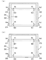
図3(a)は内部空間IS内の上端の4隅の位置の温湿度センサの配置を示す模式的水平断面図である。図3(b)は内部空間IS内の下端の4隅の位置の温湿度センサの配置を示す模式的水平断面図である。 FIG. 3A is a schematic horizontal cross-sectional view showing the arrangement of temperature / humidity sensors at the four corners of the upper end in the internal space IS. FIG. 3B is a schematic horizontal cross-sectional view showing the arrangement of temperature / humidity sensors at the four corners of the lower end in the internal space IS.
上部筐体2は、外壁201、断熱材202および内壁203により構成される。外壁201は、例えばステンレス鋼板等の金属板により形成される。内壁203は、例えば亜鉛メッキ鋼板等の金属板により形成される。断熱材202としては、例えば硬質発泡ウレタンおよびグラスウールが用いられる。
The
図3(a)に示すように、内部空間IS内の上端の4隅の位置P1~P4にそれぞれ温湿度センサSE1~SE4が取り付けられる。内部空間IS内の上端の4隅の位置P1~P4に対応して外壁201の表面上の4つの位置Pe1~Pe4にそれぞれ温度センサST1~ST4が取り付けられる。また、図3(b)に示すように、内部空間IS内の下端の4隅の位置P5~P8にそれぞれ温湿度センサSE5~SE8が取り付けられる。また、内部空間IS内の下端の4隅の位置P5~P8に対応して外壁201の表面上の4つの位置Pe5~Pe8にそれぞれ温度センサST5~ST8が取り付けられる。
As shown in FIG. 3A, temperature / humidity sensors SE1 to SE4 are attached to positions P1 to P4 at the four upper ends in the internal space IS, respectively. Temperature sensors ST1 to ST4 are attached to the four positions Pe1 to Pe4 on the surface of the
温湿度センサSE1~SE8により内部空間ISの内部温度および湿度がそれぞれ測定される。また、温度センサST1~ST8により恒温恒湿槽1の周囲温度がそれぞれ測定される。ここで、周囲温度とは、恒温恒湿槽1が設置される空間の温度である。本実施の形態では、周囲温度は、恒温恒湿槽1の外壁201の表面上の温度である。周囲温度が恒温恒湿槽1の近傍の特定の位置の温度であってもよい。
The internal temperature and humidity of the internal space IS are measured by the temperature / humidity sensors SE1 to SE8, respectively. Further, the ambient temperature of the constant temperature and humidity chamber 1 is measured by the temperature sensors ST1 to ST8, respectively. Here, the ambient temperature is the temperature of the space where the constant temperature and humidity chamber 1 is installed. In the present embodiment, the ambient temperature is the temperature on the surface of the
図1(a)の扉20が閉じられた状態で、操作盤21を用いて内部空間ISの設定温度が所定の値に設定される。また、内部空間ISの設定湿度が所定の値に設定される。それにより、内部空間ISの吹出し口41の温度および湿度がそれぞれ設定温度および設定湿度に維持されるようにコントローラ7により加湿部51、冷却・除湿部52、加熱部53および送風部54が制御される。本発明は、内部空間ISの温度特性評価方法の改善に関するため、内部空間ISの湿度特性評価方法には言及しない。そのため、本実施の形態では、温度に関する性能関数が算出される。内部温度IS内の温度は、湿度の変化の影響をほとんど受けないため、本発明では、性能関数の算出には湿度は考慮されない。性能関数は、恒温恒湿槽1に接続されたコンピュータを用いて算出される。
With the
図4は恒温恒湿槽とコンピュータとの接続を示すブロック図である。図4に示すように、パーソナルコンピュータ等のコンピュータ10は、恒温恒湿槽1のコントローラ7、温湿度センサSE1~SE8および温度センサST1~ST8に接続される。コンピュータ10は、コントローラ7から設定温度の値を設定温度データDSとして取得する。また、コンピュータ10は、温湿度センサSE1~SE8から内部温度の測定値をそれぞれ内部温度データDI1~DI8として取得し、温度センサST1~ST8から周囲温度の測定値をそれぞれ周囲温度データDA1~DA8として取得する。
FIG. 4 is a block diagram showing a connection between a constant temperature and humidity chamber and a computer. As shown in FIG. 4, a
図5および図6は性能関数の算出方法を示すフローチャートである。性能関数の算出は、複数の位置P1~P8の各々について行われるが、以下、内部空間IS内の任意の1つの位置Piについての性能関数の算出方法について説明する。ここで、iは1~8の任意の整数である。 5 and 6 are flowcharts showing a method of calculating a performance function. The calculation of the performance function is performed for each of the plurality of positions P1 to P8, and the method of calculating the performance function for any one position Pi in the internal space IS will be described below. Here, i is an arbitrary integer of 1 to 8.
まず、作業者は、操作盤21を用いて恒温恒湿槽1のコントローラ7に設定温度を入力する。恒温恒湿槽1の動作が安定した後、コンピュータ10は、コントローラ7から設定温度の値を設定温度データDSとして取得する(ステップS1)。次に、コンピュータ10は、温度センサSTiから周囲温度の測定値を周囲温度データとして取得し、温湿度センサSEiから内部温度の測定値を内部温度データとして取得する(ステップS2)。
First, the operator inputs the set temperature to the
コンピュータ10は、周囲温度データおよび内部温度データの取得回数がmに達したか否かを判定する(ステップS3)。mは1以上の整数である。周囲温度データおよび内部温度データの取得回数がm回に達していない場合、コンピュータ10はステップS2に戻り、周囲温度データおよび内部温度データを取得する。
The
周囲温度データおよび内部温度データの取得回数がm回に達した場合、コンピュータ10は、取得されたm個の周囲温度データの平均値およびm個の内部温度データの平均値をそれぞれ周囲温度データDAiおよび内部温度データDIiとして算出し(ステップS4)、設定温度データDS、周囲温度データDAiおよび内部温度データDIiの組み合わせを温度データ群として記憶する(ステップS5)。m個の周囲温度データの平均値およびm個の内部温度データの平均値を算出することによりノイズ等による周囲温度および内部温度の測定値の変動の影響を除去することができる。
When the number of acquisitions of the ambient temperature data and the internal temperature data reaches m times, the
次に、コンピュータ10は、n個の温度データ群が記憶されたか否かを判定する(ステップS6)。nは2以上の整数である。n個の温度データ群が記憶されていない場合には、作業者は、設定温度および周囲温度の少なくとも一方を変更する。コンピュータ10は、設定温度および周囲温度の少なくとも一方が変更されたか否かを判定する(ステップS7)。設定温度および周囲温度のいずれもが変更されていない場合には、コンピュータ10は、設定温度および周囲温度の少なくとも一方が変更されるまで待機する。設定温度および周囲温度の少なくとも一方が変更された場合には、コンピュータ10は、ステップS1~S7の処理を行い、他の1個の温度データ群を記憶する。
Next, the
ステップS6でn個の温度データ群が記憶されている場合には、コンピュータ10は、各温度データ群について、周囲温度データDAiと設定温度データDSとの差分(以下、第1の差分Δxと呼ぶ。)を算出する(ステップS8)。また、コンピュータ10は、各温度データ群について、内部温度データDIiと設定温度データDSとの差分(以下、第2の差分Δyと呼ぶ。)を算出する(ステップS9)。さらに、コンピュータ10は、各温度データ群について、第1の差分Δxと第2の差分Δyとの組み合わせを差分群として記憶する(ステップS10)。これにより、n個の差分群が得られる。
When n temperature data groups are stored in step S6, the
その後、コンピュータ10は、n個の差分群に基づいて性能関数を算出する(ステップS11)。具体的には、コンピュータ10は、n個の差分群を回帰分析により一次関数で近似し、その一次関数を性能関数として得る。コンピュータ10は、得られた性能関数を記憶する(ステップS12)。具体的には、性能関数の傾き係数および切片係数が記憶される。
After that, the
図7は性能関数の一例を示す概念図である。図7の横軸は周囲温度と設定温度との差(第1の差分Δx)を表し、縦軸は内部温度と設定温度との差(第2の差分Δy)を表す。以下の図8~図11においても同様である。図7に示すように、複数の差分群がΔx-Δy平面に測定点mpとしてプロットされる。複数の測定点mpの回帰分析により一次関数が性能関数Fiとして算出される。性能関数Fiは次式により表される。 FIG. 7 is a conceptual diagram showing an example of a performance function. The horizontal axis of FIG. 7 represents the difference between the ambient temperature and the set temperature (first difference Δx), and the vertical axis represents the difference between the internal temperature and the set temperature (second difference Δy). The same applies to FIGS. 8 to 11 below. As shown in FIG. 7, a plurality of difference groups are plotted as measurement points mp on the Δx−Δy plane. A linear function is calculated as a performance function Fi by regression analysis of a plurality of measurement points mp. The performance function Fi is expressed by the following equation.
Fi=Δy=A・Δx+B …(1)
上式(1)において、Aは傾き係数であり、Bは切片係数である。なお、切片係数は、温湿度センサの特性により生じる。後述するように、性能関数Fiを用いて恒温恒湿槽1の内部空間の温度特性を評価することができる。
Fi = Δy = A · Δx + B ... (1)
In the above equation (1), A is a slope coefficient and B is an intercept coefficient. The intercept coefficient is generated by the characteristics of the temperature / humidity sensor. As will be described later, the temperature characteristics of the internal space of the constant temperature and humidity chamber 1 can be evaluated using the performance function Fi.
(3)性能関数の例
図8は恒温恒湿槽1の内部空間IS内の8つの位置についての性能関数の例を示す図である。図8の例では、設定温度を20℃、40℃および60℃に設定し、8つの位置P1~P8について各設定温度での周囲温度データおよび内部温度データを取得した。それにより、8つの位置P1~P8の各々について、3個の温度データ群を取得し、3個の差分群を算出した。各差分群における第1の差分Δxと第2の差分Δyとの関係をΔx-Δy平面にプロットした。8つの位置P1~P8について、図5および図6の方法により性能関数F1~F8をそれぞれ算出した。
(3) Example of Performance Function FIG. 8 is a diagram showing an example of a performance function for eight positions in the internal space IS of the constant temperature and humidity chamber 1. In the example of FIG. 8, the set temperature was set to 20 ° C., 40 ° C., and 60 ° C., and the ambient temperature data and the internal temperature data at each set temperature were acquired for the eight positions P1 to P8. As a result, three temperature data groups were acquired for each of the eight positions P1 to P8, and three difference groups were calculated. The relationship between the first difference Δx and the second difference Δy in each difference group was plotted on the Δx−Δy plane. Performance functions F1 to F8 were calculated for the eight positions P1 to P8 by the methods of FIGS. 5 and 6, respectively.
医薬品の環境試験では、例えば、25℃±2℃、30℃±2℃または40℃±2℃の温度条件で医薬品を一定期間以上保存することが要求される。図8の例では、周囲温度と設定温度との差(第1の差分Δx)が-40℃~10℃の範囲内で内部温度と設定温度との差(第2の差分Δy)が±2℃よりも十分に小さくなっている。 In the environmental test of a drug, for example, it is required to store the drug under a temperature condition of 25 ° C ± 2 ° C, 30 ° C ± 2 ° C or 40 ° C ± 2 ° C for a certain period or longer. In the example of FIG. 8, the difference between the internal temperature and the set temperature (second difference Δy) is ± 2 while the difference between the ambient temperature and the set temperature (first difference Δx) is in the range of −40 ° C. to 10 ° C. It is sufficiently smaller than ℃.
(4)内部空間ISの温度特性に関する評価方法
(a)第2の差分許容範囲に対する第2の差分Δyの余裕度の評価
各性能関数Fiについて第2の差分許容範囲の上限値および下限値に対する第2の差分Δyの余裕度が算出される。図9は第2の差分の余裕度の算出方法の例を示す図である。
(4) Evaluation method for the temperature characteristics of the internal space IS (a) Evaluation of the margin of the second difference Δy with respect to the second difference tolerance range For each performance function Fi, the upper limit value and the lower limit value of the second difference tolerance range are obtained. The margin of the second difference Δy is calculated. FIG. 9 is a diagram showing an example of a method for calculating the margin of the second difference.
まず、第1の差分Δxの変動範囲(以下、第1の差分変動範囲と呼ぶ。)が設定される。第1の差分変動範囲は、恒温恒湿槽1が設置される空間の温度の変動範囲と設定温度とに基づいて設定される。第1の差分変動範囲の上限値をXaとし、第1の差分変動範囲の下限値を-Xbとする。 First, the fluctuation range of the first difference Δx (hereinafter, referred to as the first difference fluctuation range) is set. The first difference fluctuation range is set based on the temperature fluctuation range and the set temperature of the space in which the constant temperature and humidity chamber 1 is installed. The upper limit of the first difference fluctuation range is Xa, and the lower limit of the first difference fluctuation range is −Xb.
また、第2の差分Δyの許容範囲(以下、第2の差分許容範囲と呼ぶ。)が設定される。第2の差分許容範囲は、環境試験において規定された温度条件に設定される。第2の差分許容範囲の上限値をEaとし、第2の差分許容範囲の下限値を-Ebとする。 Further, an allowable range of the second difference Δy (hereinafter, referred to as a second allowable difference range) is set. The second difference tolerance is set to the temperature conditions specified in the environmental test. The upper limit of the second difference tolerance is Ea, and the lower limit of the second difference tolerance is −Eb.
例えば、設定温度が25℃であり、周囲温度が10℃~30℃の範囲で変動し得る場合には、第1の差分変動範囲の上限値Xaは5℃であり、第1の差分変動範囲の下限値-Xbは-15℃である。また、内部温度の許容誤差が±2℃である場合には、第2の差分許容範囲の上限値Eaは+2℃であり、第2の差分許容範囲の下限値-Ebは-2℃である。 For example, when the set temperature is 25 ° C. and the ambient temperature can fluctuate in the range of 10 ° C. to 30 ° C., the upper limit value Xa of the first difference fluctuation range is 5 ° C., and the first difference fluctuation range. The lower limit of −Xb is −15 ° C. When the tolerance of the internal temperature is ± 2 ° C., the upper limit value Ea of the second difference tolerance range is + 2 ° C., and the lower limit value −Eb of the second difference tolerance range is −2 ° C. ..
第1の差分変動範囲-Xb~Xa内で性能関数Fiについての第2の差分Δyの最大値および最小値が取得される。図9の例では、第1の差分変動範囲の上限値Xaでの第2の差分Δymaxが最大値となり、第1の差分変動範囲の下限値-Xbでの第2の差分-Δyminが最小値となる。 Within the first difference variation range-Xb to Xa, the maximum and minimum values of the second difference Δy for the performance function Fi are acquired. In the example of FIG. 9, the second difference Δymax at the upper limit value Xa of the first difference fluctuation range becomes the maximum value, and the second difference −Δymin at the lower limit value −Xb of the first difference fluctuation range becomes the minimum value. Will be.
第2の差分許容範囲の上限値Eaに対する第2の差分Δymaxの余裕度Maは、例えば次式により算出される。 The margin Ma of the second difference Δymax with respect to the upper limit value Ea of the second difference allowable range is calculated by, for example, the following equation.
Ma=Ea-Δymax …(2)
第2の差分許容範囲の下限値-Ebに対する第2の差分-Δyminの余裕度Mbは、例えば次式により算出される。
Ma = Ea-Δymax ... (2)
The margin Mb of the second difference −Δymin with respect to the lower limit value −Eb of the second difference tolerance range is calculated by, for example, the following equation.
Mb=Eb-Δymin …(3)
余裕度Ma,Mbのうち小さい値を有する余裕度が最小余裕度となる。図9の例では、余裕度Maが性能関数Fiについての最小余裕度である。
Mb = Eb-Δymin ... (3)
The margin having a smaller value among the margins Ma and Mb is the minimum margin. In the example of FIG. 9, the margin Ma is the minimum margin for the performance function Fi.
余裕度の算出方法は上記の例に限定されず、余裕度が他の方法により算出されてもよい。例えば、第2の差分許容範囲の上限値Eaに対する第2の差分Δymaxの余裕度Maおよび下限値-Ebに対する第2の差分-Δyminの余裕度Mbは次式により算出されてもよい。 The method for calculating the margin is not limited to the above example, and the margin may be calculated by another method. For example, the margin Ma of the second difference Δymax with respect to the upper limit value Ea of the second difference tolerance range and the margin Mb of the second difference −Δymin with respect to the lower limit value −Eb may be calculated by the following equations.
Ma=(Ea-Δymax)/Ea …(4)
Mb=(Eb-Δymin)/Eb …(5)
また、任意の第1の差分Δxkに対応する第2の差分Δykの余裕度は以下の方法で算出される。第2の差分Δykが正の値を有する場合には、第2の差分許容範囲の上限値Eaに対する第2の差分Δykの余裕度Mkは例えば次式(6)により算出される。
Ma = (Ea-Δymax) / Ea ... (4)
Mb = (Eb-Δymin) / Eb ... (5)
Further, the margin of the second difference Δyk corresponding to the arbitrary first difference Δxk is calculated by the following method. When the second difference Δyk has a positive value, the margin Mk of the second difference Δyk with respect to the upper limit value Ea of the second difference tolerance range is calculated by, for example, the following equation (6).
Mk=Ea-Δyk …(6)
第2の差分Δykが負の値を有する場合には、第2の差分許容範囲の下限値-Ebに対する第2の差分Δykの余裕度Mkは例えば次式(7)により算出される。
Mk = Ea-Δyk ... (6)
When the second difference Δyk has a negative value, the margin Mk of the second difference Δyk with respect to the lower limit value −Eb of the second difference tolerance range is calculated by, for example, the following equation (7).
Mk=(Eb+Δyk) …(7)
第2の差分Δykが次式により算出されてもよい。
Mk = (Eb + Δyk) ... (7)
The second difference Δyk may be calculated by the following equation.
Mk=(Ea-Δyk)/Ea …(8)
Mk=(Eb+Δyk)/Eb …(9)
これにより、周囲温度と設定温度との差の値ごとに第2の差分Δykの余裕度Mkを算出することができる。
Mk = (Ea-Δyk) / Ea ... (8)
Mk = (Eb + Δyk) / Eb ... (9)
Thereby, the margin Mk of the second difference Δyk can be calculated for each value of the difference between the ambient temperature and the set temperature.
また、性能関数Fiが得られた後の任意の時点において第2の差分Δykの余裕度が算出される。ここで、任意の時点での第2の差分Δykは次の方法で取得することができる。周囲温度を測定することにより周囲温度データDAiが得られるとともに、設定温度データDSが取得される。周囲温度データDAiおよび設定温度データDSから第1の差分Δxkが算出される。算出された第1の差分Δxkが上式(1)の性能関数Fiの第1の差分Δxに代入されることにより第2の差分Δykが算出される。この方法によれば、恒温恒湿槽1の実稼働中に内部温度を測定することなく、周囲温度を測定することにより第2の差分Δykを取得することができる。ここで、実稼働とは、恒温恒湿槽1が試験体24の環境試験のために動作することをいう。
Further, the margin of the second difference Δyk is calculated at an arbitrary time point after the performance function Fi is obtained. Here, the second difference Δyk at an arbitrary time point can be obtained by the following method. By measuring the ambient temperature, the ambient temperature data DAi is obtained, and the set temperature data DS is acquired. The first difference Δxx is calculated from the ambient temperature data DAi and the set temperature data DS. The second difference Δyk is calculated by substituting the calculated first difference Δxk into the first difference Δx of the performance function Fi of the above equation (1). According to this method, the second difference Δyk can be obtained by measuring the ambient temperature without measuring the internal temperature during the actual operation of the constant temperature and humidity chamber 1. Here, the actual operation means that the constant temperature and humidity chamber 1 operates for the environmental test of the
なお、任意の時点で周囲温度および内部温度を測定することにより第2の差分Δykが算出されてもよい。 The second difference Δyk may be calculated by measuring the ambient temperature and the internal temperature at any time point.
複数の時点で第2の差分許容範囲の上限値Eaまたは下限値-Ebに対する第2の差分Δykの余裕度Mkを算出することにより、複数の時点の間の任意の時点または将来の任意の時点における第2の差分Δyが第2の差分許容範囲内にあるか否かを推定することが可能となる。 By calculating the margin Mk of the second difference Δyk with respect to the upper limit value Ea or the lower limit value −Eb of the second difference tolerance range at a plurality of time points, any time point between the plurality of time points or any time point in the future It is possible to estimate whether or not the second difference Δy in is within the second allowable difference range.
(b)傾き係数による評価
各性能関数Fiの傾き係数Aが求められる。また、以下の方法で傾き係数Aの許容係数範囲が設定される。図10は許容係数範囲の設定方法の例を示す図である。図10の例では、性能関数Fiの切片係数Bは0とされる。
(B) Evaluation by slope coefficient The slope coefficient A of each performance function Fi is obtained. Further, the allowable coefficient range of the inclination coefficient A is set by the following method. FIG. 10 is a diagram showing an example of a method for setting an allowable coefficient range. In the example of FIG. 10, the intercept coefficient B of the performance function Fi is set to 0.
図9の例と同様に、第1の差分変動範囲-Xb~Xaおよび第2の差分許容範囲-Eb~Eaが設定される。この場合、周囲温度の変動により第1の差分Δxが第1の差分変動範囲-Xb~Xa内で変動した場合に第2の差分Δyが第2の差分許容範囲-Eb~Ea内にあるための最大の傾き係数はAmaxであり、最小の傾き係数はAminである。すなわち、性能関数の許容係数範囲はAmin以上Amax以下である。 Similar to the example of FIG. 9, the first difference fluctuation range-Xb to Xa and the second difference tolerance range-Eb to Ea are set. In this case, when the first difference Δx fluctuates within the first difference fluctuation range-Xb to Xa due to the fluctuation of the ambient temperature, the second difference Δy is within the second difference tolerance range-Eb to Ea. The maximum slope coefficient of is Amax, and the minimum slope coefficient is Amin. That is, the allowable coefficient range of the performance function is Amin or more and Amax or less.
各性能関数Fiの傾き係数Aが許容係数範囲Amin~Amax内にあると、周囲温度の変動による内部温度と設定温度との差(第2の差分Δy)の変動が第2の差分許容範囲Eb~Ea内にある。したがって、各性能関数Fiの傾き係数Aが許容係数範囲Amin~Amax内にあるか否かに基づいて周囲温度の変動による内部温度の変動が規定された許容範囲内にあるか否かを判定することができる。これにより、恒温恒湿槽1の内部空間の温度特性に関する評価を行うことができる。 When the slope coefficient A of each performance function Fi is within the allowable coefficient range Amin to Amax, the fluctuation of the difference between the internal temperature and the set temperature (second difference Δy) due to the fluctuation of the ambient temperature is the second difference allowable range Eb. It is in ~ Ea. Therefore, it is determined whether or not the fluctuation of the internal temperature due to the fluctuation of the ambient temperature is within the specified allowable range based on whether or not the slope coefficient A of each performance function Fi is within the allowable coefficient range Amin to Amax. be able to. This makes it possible to evaluate the temperature characteristics of the internal space of the constant temperature and humidity chamber 1.
許容係数範囲の設定方法は、上記の例に限定されない。例えば、最初に算出された各性能関数Fiの傾き係数Aiに所定値を加算することにより許容係数範囲の上限値を決定し、各性能関数Fiの傾き係数Aiから所定値を減算することにより許容係数範囲の下限値を決定してもよい。この場合、各性能関数Fiの傾き係数Ai±所定値の範囲が許容係数範囲として設定される。 The method of setting the allowable coefficient range is not limited to the above example. For example, the upper limit of the allowable coefficient range is determined by adding a predetermined value to the slope coefficient Ai of each performance function Fi calculated first, and the allowable value is subtracted from the slope coefficient Ai of each performance function Fi. The lower limit of the coefficient range may be determined. In this case, the range of the slope coefficient Ai ± predetermined value of each performance function Fi is set as the allowable coefficient range.
(c)決定係数による評価
複数の位置P1~P8の各々について、複数の差分群(Δx,Δy)および各性能関数Fiに基づいて各性能関数Fiの決定係数が算出される。決定係数は、実測により得られた複数の差分群(Δx,Δy)に対する性能関数Fiの当てはまりの程度を表す。各性能関数Fiについて算出された決定係数に基づいて、内部空間IS内の各位置P1~P8で性能関数を用いて温度特性を評価できるか否かを判断することができる。例えば、性能関数Fiの決定変数が予め定められたしきい値以上である場合には、当該性能関数Fiに対応する位置において性能関数を用いて温度特性を評価できると判定することができる。一方、性能関数Fiの決定変数が予め定められたしきい値よりも小さい場合には、当該性能関数Fiに対応する位置において性能関数を用いて温度特性を評価できないと判定することができる。
(C) Evaluation by coefficient of determination For each of the plurality of positions P1 to P8, the coefficient of determination of each performance function Fi is calculated based on a plurality of difference groups (Δx, Δy) and each performance function Fi. The coefficient of determination represents the degree of fit of the performance function Fi to a plurality of difference groups (Δx, Δy) obtained by actual measurement. Based on the coefficient of determination calculated for each performance function Fi, it is possible to determine whether or not the temperature characteristics can be evaluated using the performance function at each positions P1 to P8 in the internal space IS. For example, when the determination variable of the performance function Fi is equal to or higher than a predetermined threshold value, it can be determined that the temperature characteristic can be evaluated by using the performance function at the position corresponding to the performance function Fi. On the other hand, when the determination variable of the performance function Fi is smaller than the predetermined threshold value, it can be determined that the temperature characteristic cannot be evaluated by using the performance function at the position corresponding to the performance function Fi.
(d)周囲温度の変動の許容範囲の決定
各性能関数Fiを用いて各設定温度について周囲温度の変動の許容範囲を決定することができる。図11は周囲温度の変動の許容範囲の決定方法の例を示す図である。
(D) Determination of permissible range of fluctuation in ambient temperature It is possible to determine the permissible range of fluctuation in ambient temperature for each set temperature using each performance function Fi. FIG. 11 is a diagram showing an example of a method for determining an allowable range of fluctuation in ambient temperature.
第2の差分許容範囲の上限値Eaを上式(1)の性能関数Fiの第2の差分Δyに代入することにより次式が得られる。 The following equation is obtained by substituting the upper limit value Ea of the second difference tolerance range into the second difference Δy of the performance function Fi of the above equation (1).
Ea=A・Δx+B …(10)
上式(10)より次式が得られる。
Ea = A · Δx + B ... (10)
The following equation can be obtained from the above equation (10).
Δx=(Ea-B)/A=Va …(11)
上式(11)により第1の差分許容範囲の上限値Vaが算出される。
Δx = (Ea-B) / A = Va ... (11)
The upper limit value Va of the first difference tolerance range is calculated by the above equation (11).
同様に、第2の差分許容範囲の下限値-Ebを上式(1)の性能関数Fiの第2の差分Δyに代入することにより次式が得られる。 Similarly, the following equation is obtained by substituting the lower limit value −Eb of the second difference tolerance range into the second difference Δy of the performance function Fi of the above equation (1).
-Eb=A・Δx+B …(12)
上式(12)より次式が得られる。
-Eb = A · Δx + B ... (12)
The following equation can be obtained from the above equation (12).
Δx=(-Eb-B)/A=-Vb …(13)
上式(13)により第1の差分許容範囲の下限値-Vbが算出される。
Δx = (-Eb-B) / A = -Vb ... (13)
The lower limit value −Vb of the first difference tolerance range is calculated by the above equation (13).
第1の差分許容範囲の上限値Vaおよび下限値-Vbより、恒温恒湿槽1の内部温度が温度条件を満たすための周囲温度の変動の許容範囲を決定することができる。例えば、設定温度が40℃であり、第1の差分許容範囲の上限値Vaが10℃であり、下限値-Vbが-35℃である場合には、周囲温度の変動の許容範囲は5℃~50℃となる。本例では、周囲温度が5℃~50℃の範囲内で変動する場合には、恒温恒湿槽1の内部温度が温度条件を満たすことができる。 From the upper limit value Va and the lower limit value −Vb of the first difference allowable range, it is possible to determine the allowable range of fluctuation of the ambient temperature for the internal temperature of the constant temperature and humidity chamber 1 to satisfy the temperature condition. For example, when the set temperature is 40 ° C., the upper limit value Va of the first difference allowable range is 10 ° C., and the lower limit value −Vb is −35 ° C., the allowable range of fluctuation of the ambient temperature is 5 ° C. It becomes ~ 50 ° C. In this example, when the ambient temperature fluctuates within the range of 5 ° C to 50 ° C, the internal temperature of the constant temperature and humidity chamber 1 can satisfy the temperature condition.
(e)ワーストポイントおよびベストポイントの判定
本実施の形態では、恒温恒湿槽1の内部空間ISの複数の位置P1~P8について性能関数F1~F8が得られる。複数の性能関数F1~F8に基づいて以下の判定方法のいずれかにより恒温恒湿槽1の内部空間ISの温度特性に関するワーストポイントおよびベストポイントが判定される。
(E) Determination of worst point and best point In the present embodiment, performance functions F1 to F8 are obtained for a plurality of positions P1 to P8 of the internal space IS of the constant temperature and humidity chamber 1. Based on the plurality of performance functions F1 to F8, the worst point and the best point regarding the temperature characteristics of the internal space IS of the constant temperature and humidity chamber 1 are determined by any of the following determination methods.
第1の判定方法では、複数の性能関数F1~F8について算出される最小余裕度が用いられる。複数の性能関数F1~F8についての最小余裕度のうち、最も小さい最小余裕度を有する性能関数に対応する位置がワーストポイントと判定される。また、複数の性能関数F1~F8についての最小余裕度のうち、最も大きい最小余裕度を有する性能関数に対応する位置がベストポイントと判定される。 In the first determination method, the minimum margin calculated for the plurality of performance functions F1 to F8 is used. Of the minimum margins for the plurality of performance functions F1 to F8, the position corresponding to the performance function having the smallest minimum margin is determined to be the worst point. Further, among the minimum margins of the plurality of performance functions F1 to F8, the position corresponding to the performance function having the largest minimum margin is determined to be the best point.
また、任意の時点において、複数の位置P1~P8について任意の第1の差分Δxkに対応する第2の差分Δykの余裕度が算出され、最も小さい余裕度を有する位置がワーストポイントと判定され、最も大きい余裕度を有する位置がベストポイントと判定されてもよい。この場合、任意の時点で周囲温度と設定温度との差(第1の差分Δx)に応じてワーストポイントおよびベストポイントを判定することができる。 Further, at an arbitrary time point, the margin of the second difference Δyk corresponding to the arbitrary first difference Δxk is calculated for the plurality of positions P1 to P8, and the position having the smallest margin is determined to be the worst point. The position having the largest margin may be determined as the best point. In this case, the worst point and the best point can be determined according to the difference between the ambient temperature and the set temperature (first difference Δx) at any time point.
第2の判定方法では、複数の性能関数F1~F8の傾き係数Aが用いられる。この場合、複数の性能関数F1~F8の傾き係数Aの絶対値が算出される。最も大きい傾き係数Aの絶対値を有する性能関数に対応する位置がワーストポイントと判定され、最も小さい傾き係数Aの絶対値を有する性能関数に対応する位置がベストポイントと判定される。 In the second determination method, the slope coefficients A of the plurality of performance functions F1 to F8 are used. In this case, the absolute value of the slope coefficients A of the plurality of performance functions F1 to F8 is calculated. The position corresponding to the performance function having the absolute value of the largest inclination coefficient A is determined to be the worst point, and the position corresponding to the performance function having the absolute value of the smallest inclination coefficient A is determined to be the best point.
なお、第1および第2の判定方法を組み合わせることにより、ワーストポイントおよびベストポイントが判定されてもよい。 The worst point and the best point may be determined by combining the first and second determination methods.
恒温恒湿槽1の内部空間ISのワーストポイントにおける第2の差分Δyが第2の差分許容範囲内にある場合には、他の位置における第2の差分Δyも第2の差分許容範囲内にあると判断することができる。したがって、ワーストポイントにおける第2の差分Δyを監視することにより内部空間ISの全ての位置での内部温度が温度条件を満たすことを確認することができる。 When the second difference Δy at the worst point of the internal space IS of the constant temperature and humidity chamber 1 is within the second allowable difference range, the second difference Δy at other positions is also within the second allowable difference range. It can be determined that there is. Therefore, by monitoring the second difference Δy at the worst point, it can be confirmed that the internal temperature at all the positions of the internal space IS satisfies the temperature condition.
また、恒温恒湿槽1の内部空間ISのベストポイントに近い位置に試験体24を置くことにより安定な温度雰囲気内で環境試験を行うことができる。
Further, by placing the
(5)医薬品の環境試験
次に、本発明の実施の形態に係る温度特性評価方法を用いた医薬品の環境試験の例について説明する。医薬品の環境試験では、医薬品が一定の温度条件および一定の湿度条件を満たす環境下で一定期間保存され、効能が維持されるか否かが試験される。例えば、長期保存試験の温度条件は25℃±2℃または30℃±2℃であり、最小試験期間は12か月である。加速試験の温度条件は40℃±2℃であり、最小試験期間は6か月である。このような環境試験が規定の温度条件を満足する環境下で行われたことを保証するために、恒温恒湿槽1の温度特性を評価する必要がある。
(5) Environmental test of pharmaceutical products Next, an example of an environmental test of pharmaceutical products using the temperature characteristic evaluation method according to the embodiment of the present invention will be described. In the environmental test of a drug, it is tested whether or not the drug is stored for a certain period of time in an environment satisfying a certain temperature condition and a certain humidity condition, and the efficacy is maintained. For example, the temperature condition of the long-term storage test is 25 ° C ± 2 ° C or 30 ° C ± 2 ° C, and the minimum test period is 12 months. The temperature condition of the accelerated test is 40 ° C ± 2 ° C, and the minimum test period is 6 months. In order to ensure that such an environmental test was performed in an environment satisfying the specified temperature conditions, it is necessary to evaluate the temperature characteristics of the constant temperature and humidity chamber 1.
図12は医薬品の環境試験の例を示す図である。まず、工場において恒温恒湿槽1が製造された後、出荷前の検査の時点t1で恒温恒湿槽1の内部空間ISの温度特性が評価される。時点t1の評価においては、恒温恒湿槽1に複数の温湿度センサSE1~SE8および複数の温度センサST1~ST8が取り付けられ、図5および図6の方法で、内部空間ISの複数の位置P1~P8について性能関数F1~F8が算出される。複数の性能関数F1~F8を用いて位置P1~P8について上記の方法により温度特性の評価が行われる。例えば、全ての性能関数F1~F8について、最小余裕度が所定の基準値以上となり、傾き係数Aの絶対値が所定の基準値以下となり、複数の性能関数F1~F8の決定係数が所定の基準値以上となることが確認される。 FIG. 12 is a diagram showing an example of an environmental test for a pharmaceutical product. First, after the constant temperature and humidity chamber 1 is manufactured in the factory, the temperature characteristics of the internal space IS of the constant temperature and humidity chamber 1 are evaluated at the time t1 of the inspection before shipment. In the evaluation at time point t1, a plurality of temperature / humidity sensors SE1 to SE8 and a plurality of temperature sensors ST1 to ST8 are attached to the constant temperature / humidity constant chamber 1, and a plurality of positions P1 of the internal space IS are attached by the methods of FIGS. 5 and 6. Performance functions F1 to F8 are calculated for ~ P8. The temperature characteristics of the positions P1 to P8 are evaluated by the above method using a plurality of performance functions F1 to F8. For example, for all the performance functions F1 to F8, the minimum margin is equal to or more than a predetermined reference value, the absolute value of the slope coefficient A is equal to or less than a predetermined reference value, and the coefficient of determination of a plurality of performance functions F1 to F8 is a predetermined reference. It is confirmed that it exceeds the value.
次に、恒温恒湿槽1が納入先の建物の部屋内に設置された時点t2で恒温恒湿槽1の内部空間ISの温度特性が評価される。時点t2の評価においては、時点t1での評価と同様に、内部空間ISの複数の位置P1~P8について性能関数F1~F8が算出され、算出された性能関数F1~F8を用いて位置P1~P8について上記の方法により温度特性の評価が行われる。時点t2の評価は、恒温恒湿槽1の内部空間IS内に試験体24が置かれていない状態および試験体24が置かれた状態で行われる。
Next, the temperature characteristic of the internal space IS of the constant temperature and humidity chamber 1 is evaluated at t2 when the constant temperature and humidity chamber 1 is installed in the room of the delivery destination building. In the evaluation at the time point t2, the performance functions F1 to F8 are calculated for the plurality of positions P1 to P8 of the internal space IS as in the evaluation at the time point t1, and the calculated performance functions F1 to F8 are used to calculate the positions P1 to F8. The temperature characteristics of P8 are evaluated by the above method. The evaluation at the time point t2 is performed in a state where the
その後、環境試験の開始の時点t3で恒温恒湿槽1の内部空間ISの温度特性が評価される。時点t3の評価は、恒温恒湿槽1の内部空間IS内に試験体24が置かれた状態で行われる。なお、恒温恒湿槽1の内部空間IS内に試験体24が置かれる前にも評価が行われてもよい。
Then, at the time t3 at the start of the environmental test, the temperature characteristics of the internal space IS of the constant temperature and humidity chamber 1 are evaluated. The evaluation at time point t3 is performed with the
この場合、内部空間ISの複数の位置P1~P8の各々について第2の差分Δyが取得され、取得された各第2の差分Δyの余裕度が評価される。また、内部空間ISの複数の位置P1~P8について複数の性能関数F1~F8が算出され、複数の性能関数F1~F8について余裕度、傾き係数または決定係数が評価されてもよい。あるいは、内部空間ISのワーストポイントのみについて第2の差分Δyが取得され、取得された第2の差分Δyの余裕度が評価されてもよい。また、内部空間ISのワーストポイントのみについて性能関数が算出され、算出された性能関数について余裕度、傾き係数または決定係数が評価されてもよい。 In this case, the second difference Δy is acquired for each of the plurality of positions P1 to P8 of the internal space IS, and the margin of each acquired second difference Δy is evaluated. Further, a plurality of performance functions F1 to F8 may be calculated for a plurality of positions P1 to P8 of the internal space IS, and a margin, a slope coefficient, or a coefficient of determination may be evaluated for the plurality of performance functions F1 to F8. Alternatively, the second difference Δy may be acquired only for the worst point of the internal space IS, and the margin of the acquired second difference Δy may be evaluated. Further, the performance function may be calculated only for the worst point of the internal space IS, and the margin, the slope coefficient, or the coefficient of determination may be evaluated for the calculated performance function.
環境試験の開始の時点t3から一定期間ΔT経過後の時点t4で、恒温恒湿槽1の内部空間ISの温度特性が評価される。時点t4の評価では、一時的に扉20が開かれ、複数の温湿度センサSE1~SE8および複数の温度センサST1~ST8が取り付けられた後、扉20が閉じられる。その後、恒温恒湿槽1の温湿度センサSE0の測定値が設定温度で安定した後、位置P1~P8の各々についての内部温度および周囲温度が測定されることにより第2の差分Δyが取得され、取得された各第2の差分Δyの余裕度が評価される。
The temperature characteristics of the internal space IS of the constant temperature and humidity chamber 1 are evaluated at the time point t4 after the elapse of ΔT for a certain period from the time point t3 at the start of the environmental test. In the evaluation at time point t4, the
時点t4においても、内部空間ISの複数の位置P1~P8について複数の性能関数F1~F8が算出され、複数の性能関数F1~F8について余裕度、傾き係数または決定係数が評価されてもよい。あるいは、内部空間ISのワーストポイントのみについて第2の差分Δyが取得され、取得された第2の差分Δyの余裕度が評価されてもよい。また、内部空間ISのワーストポイントのみについて性能関数が算出され、算出された性能関数について余裕度、傾き係数または決定係数が評価されてもよい。 At the time point t4, a plurality of performance functions F1 to F8 may be calculated for the plurality of positions P1 to P8 of the internal space IS, and a margin, a slope coefficient, or a coefficient of determination may be evaluated for the plurality of performance functions F1 to F8. Alternatively, the second difference Δy may be acquired only for the worst point of the internal space IS, and the margin of the acquired second difference Δy may be evaluated. Further, the performance function may be calculated only for the worst point of the internal space IS, and the margin, the slope coefficient, or the coefficient of determination may be evaluated for the calculated performance function.
時点t4の評価において、位置P1~P8の内部温度が測定されることなく位置Pe1~Pe8の周囲温度のみが測定されてもよい。この場合、周囲温度および設定温度に基づいて第1の差分Δxの値が算出され、第1の差分Δxの値が上式(1)の第1の差分Δxに代入されることにより第2の差分Δyが算出される。取得された各第2の差分Δyが第2の差分許容範囲(例えば±2℃)内にあるか否かが確認されるとともに、各第2の差分Δyの余裕度が評価される。あるいは、内部空間ISのワーストポイントのみについて第2の差分Δyが取得され、取得された第2の差分Δyが第2の差分許容範囲内にあるか否かが確認されるとともに、第2の差分Δyの余裕度が評価される。ワーストポイントについての第2の差分Δyの値が第2の差分許容範囲内にある場合には、他の位置についての第2の差分Δyの値も第2の差分許容範囲内にあると推定される。 In the evaluation at time point t4, only the ambient temperature at positions Pe1 to Pe8 may be measured without measuring the internal temperature at positions P1 to P8. In this case, the value of the first difference Δx is calculated based on the ambient temperature and the set temperature, and the value of the first difference Δx is substituted into the first difference Δx in the above equation (1) to obtain the second difference Δx. The difference Δy is calculated. Whether or not each of the acquired second differences Δy is within the second allowable difference range (for example, ± 2 ° C.) is confirmed, and the margin of each second difference Δy is evaluated. Alternatively, the second difference Δy is acquired only for the worst point of the internal space IS, and it is confirmed whether or not the acquired second difference Δy is within the second difference allowable range, and the second difference is obtained. The margin of Δy is evaluated. If the value of the second difference Δy for the worst point is within the second tolerance, it is presumed that the value of the second difference Δy for the other position is also within the second tolerance. To.
時点t3の評価により算出された性能関数F1~F8ならびに時点t4の評価により得られた第2の差分Δyに基づいて、時点t3から時点t4までの期間における各位置P1~P8の内部温度と設定温度との差が第2の差分許容範囲内に維持されたか否かを推定することができる。また、時点t3の評価により算出された性能関数F1~F8ならびに時点t4の評価により算出された性能関数F1~F8に基づいて時点t3から時点t4までの内部空間の温度特性の変化の有無を推定することができる。 Based on the performance functions F1 to F8 calculated by the evaluation of the time point t3 and the second difference Δy obtained by the evaluation of the time point t4, the internal temperature and setting of each position P1 to P8 in the period from the time point t3 to the time point t4. It can be estimated whether the difference from the temperature is maintained within the second difference tolerance. Further, it is estimated whether or not there is a change in the temperature characteristics of the internal space from the time point t3 to the time point t4 based on the performance functions F1 to F8 calculated by the evaluation of the time point t3 and the performance functions F1 to F8 calculated by the evaluation of the time point t4. can do.
時点t4の評価では、ワーストポイントのみの第2の差分Δyが取得されてもよい。この場合、ワーストポイントについての第2の差分Δyが第2の差分許容範囲内にある場合には、他の位置についての第2の差分Δyも第2の差分許容範囲内にあると推定される。また、内部空間ISのワーストポイントのみについて性能関数が算出され、算出された性能関数について余裕度、傾き係数または決定係数が評価されてもよい。 In the evaluation at the time point t4, the second difference Δy of only the worst point may be acquired. In this case, if the second difference Δy for the worst point is within the second difference tolerance, it is estimated that the second difference Δy for the other position is also within the second difference tolerance. .. Further, the performance function may be calculated only for the worst point of the internal space IS, and the margin, the slope coefficient, or the coefficient of determination may be evaluated for the calculated performance function.
時点t4から一定期間ΔT経過後の時点t5で、時点t4と同様の方法で恒温恒湿槽1の内部空間ISの温度特性が評価される。時点t2または時点t3で算出された性能関数F1~F8ならびに時点t4および時点t5で取得された第2の差分Δyに基づいて、時点t3から時点t4までの期間および時点t4から時点t5までの期間における各位置P1~P8の内部温度と設定温度との差が第2の差分許容範囲内に維持されたか否かを推定することができる。また、時点t4の評価により算出された性能関数F1~F8ならびに時点t5の評価により算出された性能関数F1~F8に基づいて時点t4から時点t5までの内部空間の温度特性の変化の有無を推定することができる。 At the time point t5 after a certain period of time ΔT has elapsed from the time point t4, the temperature characteristics of the internal space IS of the constant temperature and humidity chamber 1 are evaluated by the same method as the time point t4. The period from time point t3 to time point t4 and the period from time point t4 to time point t5 based on the performance functions F1 to F8 calculated at time point t2 or time point t3 and the second difference Δy obtained at time point t4 and time point t5. It is possible to estimate whether or not the difference between the internal temperature of each position P1 to P8 and the set temperature in the second position is maintained within the second allowable difference range. Further, it is estimated whether or not there is a change in the temperature characteristics of the internal space from the time point t4 to the time point t5 based on the performance functions F1 to F8 calculated by the evaluation of the time point t4 and the performance functions F1 to F8 calculated by the evaluation of the time point t5. can do.
また、時点t3から時点t4までの期間および時点t4から時点t5までの期間における周囲温度を測定することにより、性能関数F1~F8に基づいて任意の時点における第2の差分Δyを取得することができる。それにより、時点t3から時点t4までの期間および時点t4から時点t5までの期間における任意の時点で各位置P1~P8での内部温度が温度条件を満たしたことを保証することができる。 Further, by measuring the ambient temperature in the period from the time point t3 to the time point t4 and the period from the time point t4 to the time point t5, it is possible to obtain the second difference Δy at any time point based on the performance functions F1 to F8. can. Thereby, it can be guaranteed that the internal temperature at each position P1 to P8 satisfies the temperature condition at any time point in the period from the time point t3 to the time point t4 and the period from the time point t4 to the time point t5.
(6)実施の形態の効果
本実施の形態に係る温度特性評価方法において得られる性能関数Fiは、周囲温度が内部温度と設定温度との差に与える影響を表している。この性能関数Fiにおける第1の差分Δxは、設定温度および周囲温度のうち少なくとも一方を変更することにより得られるため、周囲温度を大きく変化させることなく広い温度範囲で第1の差分Δxの値を得ることができる。そのため、性能関数Fiを高い精度で算出することができる。このような性能関数Fiを用いることにより、任意の時点の内部温度を高い精度で推定することが可能となる。したがって、低コストでかつ高い信頼性で環境試験装置の内部空間ISの温度特性を評価することが可能となる。その結果、環境試験の期間中の恒温恒湿槽1の性能を低コストでかつ高い信頼性で保証することが可能となる。
(6) Effect of the Embodiment The performance function Fi obtained in the temperature characteristic evaluation method according to the present embodiment represents the influence of the ambient temperature on the difference between the internal temperature and the set temperature. Since the first difference Δx in this performance function Fi is obtained by changing at least one of the set temperature and the ambient temperature, the value of the first difference Δx can be obtained in a wide temperature range without significantly changing the ambient temperature. Obtainable. Therefore, the performance function Fi can be calculated with high accuracy. By using such a performance function Fi, it is possible to estimate the internal temperature at an arbitrary time point with high accuracy. Therefore, it is possible to evaluate the temperature characteristics of the internal space IS of the environmental test apparatus at low cost and with high reliability. As a result, it is possible to guarantee the performance of the constant temperature and humidity chamber 1 during the environmental test at low cost and with high reliability.
また、恒温恒湿槽1の設定温度を変更する場合には、恒温恒湿槽1の周囲温度を変更する場合に比べて温度が安定するまでの時間が短く、かつ消費電力が小さい。本実施の形態に係る温度特性評価方法では、周囲温度を変更せずに設定温度を変更することにより性能関数Fiを算出することも可能である。それにより、待ち時間および消費電力の低減が可能となる。 Further, when the set temperature of the constant temperature and humidity chamber 1 is changed, the time until the temperature stabilizes is shorter and the power consumption is smaller than that when the ambient temperature of the constant temperature and humidity chamber 1 is changed. In the temperature characteristic evaluation method according to the present embodiment, it is also possible to calculate the performance function Fi by changing the set temperature without changing the ambient temperature. As a result, waiting time and power consumption can be reduced.
(7)他の実施の形態
上記実施の形態では、恒温恒湿槽1の内部空間ISの温度を設定温度に制御するための温湿度センサSE0が吹出し口41の近傍に配置されているが、温湿度センサSE0が吸込み口42の近傍に配置されてもよく、温湿度センサSE0が吹出し口41の近傍および吸込み口42の近傍に配置されてもよく、温湿度センサSE0が内部空間IS内の他の位置に配置されてもよい。
(7) Other Embodiments In the above embodiment, the temperature / humidity sensor SE0 for controlling the temperature of the internal space IS of the constant temperature / humidity chamber 1 to the set temperature is arranged in the vicinity of the
上記実施の形態では、周囲温度を測定するための複数の温度センサST1~ST8が恒温恒湿槽1の外壁201の表面上に接触するように配置されているが、複数の温度センサST1~ST8が恒温恒湿槽1の外壁201の近傍の空間に配置されてもよい。また、複数の温湿度センサSE1~SE8に対して共通に1つまたは複数の温度センサが配置されてもよい。
In the above embodiment, a plurality of temperature sensors ST1 to ST8 for measuring the ambient temperature are arranged so as to be in contact with the surface of the
上記実施の形態では、複数の性能関数F1~F8を算出するためにコントローラ7にコンピュータ10が接続されるが、コントローラ7がコンピュータ10の機能を有してもよい。
In the above embodiment, the
1…恒温恒湿槽,2…上部筐体,3…下部筐体,4…隔壁,5…空調空間,6…排気通路,7…コントローラ,10…コンピュータ,20…扉,21…操作盤,22…表示器,23…棚板,24…試験体,31…空気導入口,32…圧縮器,33…冷却ファン,34…凝縮器,35,36,37…冷媒配管,38…電磁開閉弁,39…膨張弁,41…吹出し口,42…吸込み口,51…加湿部,51a…パン,51b…シーズヒータ,52…冷却・除湿部,53…加熱部,54…送風部,61…排気口,201…外壁,202…断熱材,203…内壁,DA1~DA8,DAi…周囲温度データ,DI1~DI8,DIi…内部温度データ,DS…設定温度データ,Ea,Va,Xa…上限値,-Eb,-Vb,-Xb…下限値,F1~F8,Fi…性能関数,IS…内部空間,mp…測定点,P1~P8,Pe1~Pe8,Pi…位置,SE0,SE1~SE8,SEi…温湿度センサ,ST1~ST8,STi…温度センサ,ΔT…一定期間,Δx…第1の差分,Δy…第2の差分,Δymax…第2の差分の最大値,-Δymin…第2の差分の最小値 1 ... constant temperature and humidity chamber, 2 ... upper housing, 3 ... lower housing, 4 ... partition wall, 5 ... air conditioning space, 6 ... exhaust passage, 7 ... controller, 10 ... computer, 20 ... door, 21 ... operation panel, 22 ... Display, 23 ... Shelf board, 24 ... Test piece, 31 ... Air inlet, 32 ... Compressor, 33 ... Cooling fan, 34 ... Condensator, 35, 36, 37 ... Refrigerator piping, 38 ... Electromagnetic on-off valve , 39 ... Expansion valve, 41 ... Blowout port, 42 ... Suction port, 51 ... Humidity section, 51a ... Pan, 51b ... Seeds heater, 52 ... Cooling / dehumidifying section, 53 ... Heating section, 54 ... Blower section, 61 ... Exhaust Mouth, 201 ... outer wall, 202 ... heat insulating material, 203 ... inner wall, DA1 to DA8, DAi ... ambient temperature data, DI1 to DI8, DIi ... internal temperature data, DS ... set temperature data, Ea, Va, Xa ... upper limit, -Eb, -Vb, -Xb ... Lower limit value, F1 to F8, Fi ... Performance function, IS ... Internal space, mp ... Measurement point, P1 to P8, Pe1 to Pe8, Pi ... Position, SE0, SE1 to SE8, SEi ... temperature / humidity sensor, ST1 to ST8, STi ... temperature sensor, ΔT ... fixed period, Δx ... first difference, Δy ... second difference, Δymax ... maximum value of second difference, -Δymin ... second difference Minimum value of
Claims (14)
前記環境試験装置の設定温度を第一の設定温度を示す第一の設定温度データとして取得し、前記環境試験装置が設置された空間の温度である周囲温度を第一の周囲温度データとして取得するとともに、前記内部空間の内部温度を測定することにより第一の内部温度データを取得するステップと、
前記環境試験装置の前記設定温度を前記第一の設定温度とは異なる第二の設定温度に変更し、前記第二の設定温度に設定された際の、第二の設定温度データと、前記環境試験装置が設置された空間の温度である第二の周囲温度データと、前記内部空間の内部温度である第二の内部温度データを取得するステップと、
前記第一の設定温度データと、前記第一の設定温度に設定された際の、前記第一の周囲温度データと前記第一の内部温度データとの組み合わせからなる第一の温度データ群と、前記第二の設定温度データと、前記第二の設定温度に設定された際の、前記第二の周囲温度データと前記第二の内部温度データとの組み合わせからなる第二の温度データ群を取得するステップと、
前記第一の温度データ群と前記第二の温度データ群の各々に対して、周囲温度データと設定温度データとの差分を第1の差分として算出し、内部温度データと設定温度データとの差分を第2の差分として算出し、前記第一の温度データ群に対する前記第1及び第2の差分の組み合わせと、前記第二の温度データ群に対する前記第1及び第2の差分の組み合わせとを差分群として得るステップと、
前記第一の温度データ群と前記第二の温度データ群の各々に対する前記差分群を回帰分析で近似し、前記近似により得られた関数を性能関数として得るステップと、
前記性能関数を用いて前記環境試験装置の内部空間の温度特性に関する評価を行うステップとを含む、温度特性評価方法。 A temperature characteristic evaluation method for evaluating the temperature characteristics of the internal space of an environmental test device that has an internal space and operates so as to maintain the temperature of the internal space at a predetermined set temperature.
The set temperature of the environmental test device is acquired as the first set temperature data indicating the first set temperature, and the ambient temperature, which is the temperature of the space in which the environmental test device is installed, is acquired as the first ambient temperature data. At the same time, the step of acquiring the first internal temperature data by measuring the internal temperature of the internal space, and
The second set temperature data when the set temperature of the environmental test apparatus is changed to a second set temperature different from the first set temperature and set to the second set temperature, and the environment. A step of acquiring a second ambient temperature data which is the temperature of the space where the test device is installed and a second internal temperature data which is the internal temperature of the internal space.
A first temperature data group consisting of a combination of the first set temperature data, the first ambient temperature data and the first internal temperature data when the first set temperature is set, and the like. Acquire a second temperature data group consisting of a combination of the second set temperature data, the second ambient temperature data and the second internal temperature data when the second set temperature is set. Steps to do and
For each of the first temperature data group and the second temperature data group, the difference between the ambient temperature data and the set temperature data is calculated as the first difference, and the difference between the internal temperature data and the set temperature data. Is calculated as the second difference, and the difference between the combination of the first and second differences with respect to the first temperature data group and the combination of the first and second differences with respect to the second temperature data group. Steps to get as a group and
A step of approximating the difference group for each of the first temperature data group and the second temperature data group by regression analysis and obtaining the function obtained by the approximation as a performance function.
A temperature characteristic evaluation method including a step of evaluating the temperature characteristics of the internal space of the environmental test apparatus using the performance function.
Priority Applications (4)
| Application Number | Priority Date | Filing Date | Title |
|---|---|---|---|
| JP2017255089A JP7079955B2 (en) | 2017-12-29 | 2017-12-29 | Temperature characterization method |
| US16/209,358 US20190203963A1 (en) | 2017-12-29 | 2018-12-04 | Temperature characteristic evaluation method |
| CN201811625116.9A CN109991153B (en) | 2017-12-29 | 2018-12-28 | Temperature characteristic evaluation method |
| US17/315,426 US11614248B2 (en) | 2017-12-29 | 2021-05-10 | Temperature characteristic evaluation method |
Applications Claiming Priority (1)
| Application Number | Priority Date | Filing Date | Title |
|---|---|---|---|
| JP2017255089A JP7079955B2 (en) | 2017-12-29 | 2017-12-29 | Temperature characterization method |
Publications (3)
| Publication Number | Publication Date |
|---|---|
| JP2019120568A JP2019120568A (en) | 2019-07-22 |
| JP2019120568A5 JP2019120568A5 (en) | 2021-02-12 |
| JP7079955B2 true JP7079955B2 (en) | 2022-06-03 |
Family
ID=67059450
Family Applications (1)
| Application Number | Title | Priority Date | Filing Date |
|---|---|---|---|
| JP2017255089A Active JP7079955B2 (en) | 2017-12-29 | 2017-12-29 | Temperature characterization method |
Country Status (3)
| Country | Link |
|---|---|
| US (2) | US20190203963A1 (en) |
| JP (1) | JP7079955B2 (en) |
| CN (1) | CN109991153B (en) |
Families Citing this family (6)
| Publication number | Priority date | Publication date | Assignee | Title |
|---|---|---|---|---|
| JP6732391B2 (en) * | 2018-06-12 | 2020-07-29 | 日本電信電話株式会社 | Calculating device, calculating method and program |
| CN112578133B (en) * | 2019-09-27 | 2024-07-05 | 深圳迈瑞生物医疗电子股份有限公司 | Sample analysis system and test management method of analysis equipment |
| CN111707782A (en) * | 2020-03-30 | 2020-09-25 | 江苏方天电力技术有限公司 | Thermal power generating unit carbon dioxide emission concentration abnormity detection method based on oxygen amount |
| JP2022181926A (en) * | 2021-05-27 | 2022-12-08 | 富士電機株式会社 | Temperature adjustment device, testing device, and temperature adjustment method |
| TWI785860B (en) * | 2021-10-25 | 2022-12-01 | 謝德風 | Three-temperature multi-point uniform temperature gas split flow temperature control system |
| CN114646664B (en) * | 2022-05-20 | 2022-08-12 | 领合(南通)新型建材科技有限公司 | Novel composite door and window profile heat insulation performance quality monitoring method and system |
Citations (6)
| Publication number | Priority date | Publication date | Assignee | Title |
|---|---|---|---|---|
| JP2005229758A (en) | 2004-02-13 | 2005-08-25 | Tyrell Express Kk | System for managing energy consumption |
| JP2008275345A (en) | 2007-04-25 | 2008-11-13 | Nagano Science Kk | State estimation method in closed space, and device for monitoring temperature state of thermostatic bath by using the method |
| JP2010107062A (en) | 2008-10-28 | 2010-05-13 | Nagano Science Kk | Method of controlling air-conditioning device, air-conditioning device and environment testing device |
| JP2014134360A (en) | 2013-01-11 | 2014-07-24 | Panasonic Corp | Room temperature estimation device and program |
| WO2017056403A1 (en) | 2015-10-01 | 2017-04-06 | パナソニックIpマネジメント株式会社 | Air conditioning control method, air conditioning control device, and air conditioning control program |
| JP2017090343A (en) | 2015-11-13 | 2017-05-25 | スガ試験機株式会社 | Weather meter |
Family Cites Families (21)
| Publication number | Priority date | Publication date | Assignee | Title |
|---|---|---|---|---|
| JP2988316B2 (en) * | 1995-03-28 | 1999-12-13 | 住友電装株式会社 | Clamp for wire harness |
| JP4554535B2 (en) * | 2006-02-24 | 2010-09-29 | エスペック株式会社 | Environmental test equipment |
| EP3285192A1 (en) * | 2006-04-18 | 2018-02-21 | BlackBerry Limited | Providing access to in case of emergency information on a portable device |
| JP4884097B2 (en) * | 2006-06-21 | 2012-02-22 | 東光電気株式会社 | Environmental evaluation system and air conditioning system |
| JP4805963B2 (en) * | 2008-03-12 | 2011-11-02 | エスペック株式会社 | Environmental test method and environmental test apparatus |
| US8306772B2 (en) * | 2008-10-13 | 2012-11-06 | Apple Inc. | Method for estimating temperature at a critical point |
| JP5525960B2 (en) * | 2010-08-10 | 2014-06-18 | アズビル株式会社 | Air conditioning control apparatus and method |
| US8620632B2 (en) * | 2011-06-24 | 2013-12-31 | International Business Machines Corporation | Estimating building thermal properties by integrating heat transfer inversion model with clustering and regression techniques for a portfolio of existing buildings |
| JP5884124B2 (en) * | 2012-02-03 | 2016-03-15 | ナガノサイエンス株式会社 | control unit |
| CN103376805B (en) * | 2012-04-17 | 2015-07-29 | 深圳迈瑞生物医疗电子股份有限公司 | For temperature-controlled process and the reaction cup cleaning method of in-vitro diagnosis equipment |
| JP2014009923A (en) * | 2012-07-02 | 2014-01-20 | Nippon Telegr & Teleph Corp <Ntt> | Air conditioning control system and air conditioning control method |
| US10253996B2 (en) * | 2013-06-17 | 2019-04-09 | Mitsubishi Electric Corporation | Air-conditioning system control device and air-conditioning system control method |
| US20140379298A1 (en) * | 2013-06-21 | 2014-12-25 | Apogee Interactive, Inc. | Systems and Methods for Monitoring Energy Usage via Thermostat-Centered Approaches and Deriving Building Climate Analytics |
| CN103759851A (en) * | 2014-02-18 | 2014-04-30 | 悉雅特万科思自动化(杭州)有限公司 | Temperature compensation method used for thermal resistance collecting module |
| JP6258110B2 (en) * | 2014-04-14 | 2018-01-10 | エスペック株式会社 | Environmental test apparatus and temperature / humidity control method |
| CN105318644B (en) * | 2015-03-13 | 2017-11-17 | 合肥美的电冰箱有限公司 | Refrigerator temperature control method and device |
| CN106546357B (en) * | 2015-09-23 | 2020-06-02 | 中兴通讯股份有限公司 | Method and device for detecting environment temperature and electronic equipment |
| US10101049B2 (en) * | 2015-11-12 | 2018-10-16 | Oracle International Corporation | Determining parameters of air-cooling mechanisms |
| JP6566049B2 (en) * | 2016-01-21 | 2019-08-28 | 富士通株式会社 | Power demand value calculation system, power demand value calculation method, and power demand value calculation program |
| CN107368128B (en) * | 2016-05-11 | 2021-02-12 | 北京小焙科技有限公司 | Method and system for adjusting temperature of temperature field |
| US10970128B2 (en) * | 2018-04-13 | 2021-04-06 | Samsung Electronics Co., Ltd. | Server, air conditioner and method for controlling thereof |
-
2017
- 2017-12-29 JP JP2017255089A patent/JP7079955B2/en active Active
-
2018
- 2018-12-04 US US16/209,358 patent/US20190203963A1/en not_active Abandoned
- 2018-12-28 CN CN201811625116.9A patent/CN109991153B/en active Active
-
2021
- 2021-05-10 US US17/315,426 patent/US11614248B2/en active Active
Patent Citations (6)
| Publication number | Priority date | Publication date | Assignee | Title |
|---|---|---|---|---|
| JP2005229758A (en) | 2004-02-13 | 2005-08-25 | Tyrell Express Kk | System for managing energy consumption |
| JP2008275345A (en) | 2007-04-25 | 2008-11-13 | Nagano Science Kk | State estimation method in closed space, and device for monitoring temperature state of thermostatic bath by using the method |
| JP2010107062A (en) | 2008-10-28 | 2010-05-13 | Nagano Science Kk | Method of controlling air-conditioning device, air-conditioning device and environment testing device |
| JP2014134360A (en) | 2013-01-11 | 2014-07-24 | Panasonic Corp | Room temperature estimation device and program |
| WO2017056403A1 (en) | 2015-10-01 | 2017-04-06 | パナソニックIpマネジメント株式会社 | Air conditioning control method, air conditioning control device, and air conditioning control program |
| JP2017090343A (en) | 2015-11-13 | 2017-05-25 | スガ試験機株式会社 | Weather meter |
Also Published As
| Publication number | Publication date |
|---|---|
| CN109991153A (en) | 2019-07-09 |
| US20190203963A1 (en) | 2019-07-04 |
| US20210262681A1 (en) | 2021-08-26 |
| JP2019120568A (en) | 2019-07-22 |
| US11614248B2 (en) | 2023-03-28 |
| CN109991153B (en) | 2024-02-23 |
Similar Documents
| Publication | Publication Date | Title |
|---|---|---|
| JP7079955B2 (en) | Temperature characterization method | |
| CN105864954B (en) | Rise the system and method for compensation for heat | |
| US20170016642A1 (en) | Systems for Calibrating Airflow Rates in Heating, Ventilating, and Air Conditioning (HVAC) Ducts and HVAC Systems Including the Same | |
| CA2836461C (en) | Methods and apparatus for differential energy based airside economizer changeover | |
| CN104501360B (en) | Air-conditioner and its dehumidification control method | |
| US10161774B2 (en) | Systems and computer program products for measuring airflow rates in heating, ventilating, and air conditioning (HVAC) ducts and HVAC systems including the same | |
| US20130055744A1 (en) | Auxiliary ambient air refrigeration system for cooling and controlling humidity in an enclosure | |
| US20150144323A1 (en) | Central cooling system and controlling method for the same | |
| US9091454B2 (en) | Air change rate measurement and control | |
| EP2863137A1 (en) | Systems and methods for ventilating a building | |
| JP5884124B2 (en) | control unit | |
| KR101691881B1 (en) | The ventilation and air conditioning systems for environment test equipment | |
| JP2010107218A (en) | Method and device for measuring humidity distribution, and environment testing device | |
| TW201512607A (en) | Operation control device and operation control method | |
| US10285304B1 (en) | Rack-level test room | |
| JP2015132388A (en) | Air conditioning control method and air conditioning control system | |
| JP7231374B2 (en) | Indoor thermal environment analysis method | |
| US10605838B2 (en) | System and method for submetering of a heating, ventilation, and/or air conditioning (HVAC) system | |
| US20240077222A1 (en) | System and method for humidification temperature compensation | |
| JP6357889B2 (en) | Refrigerated warehouse | |
| US20240271804A1 (en) | Hvac efficiency boosting fan system, apparatus and method | |
| Sharma et al. | Determination of optimal location for sensors implementing non-invasive methods for evaluating the capacity of Window Air Conditioner | |
| JP2019002590A (en) | Facility management system and control method for facility management system | |
| JP2019164056A (en) | Fresh air leakage amount measurement method and fresh air leakage amount measuring device | |
| JPH0472135B2 (en) |
Legal Events
| Date | Code | Title | Description |
|---|---|---|---|
| A521 | Request for written amendment filed |
Free format text: JAPANESE INTERMEDIATE CODE: A523 Effective date: 20201218 |
|
| A621 | Written request for application examination |
Free format text: JAPANESE INTERMEDIATE CODE: A621 Effective date: 20201218 |
|
| A131 | Notification of reasons for refusal |
Free format text: JAPANESE INTERMEDIATE CODE: A131 Effective date: 20220118 |
|
| A521 | Request for written amendment filed |
Free format text: JAPANESE INTERMEDIATE CODE: A523 Effective date: 20220318 |
|
| TRDD | Decision of grant or rejection written | ||
| A01 | Written decision to grant a patent or to grant a registration (utility model) |
Free format text: JAPANESE INTERMEDIATE CODE: A01 Effective date: 20220426 |
|
| A61 | First payment of annual fees (during grant procedure) |
Free format text: JAPANESE INTERMEDIATE CODE: A61 Effective date: 20220517 |
|
| R150 | Certificate of patent or registration of utility model |
Ref document number: 7079955 Country of ref document: JP Free format text: JAPANESE INTERMEDIATE CODE: R150 |