JP7078394B2 - Pachinko machine - Google Patents

Pachinko machine Download PDF

Info

Publication number
JP7078394B2
JP7078394B2 JP2017252705A JP2017252705A JP7078394B2 JP 7078394 B2 JP7078394 B2 JP 7078394B2 JP 2017252705 A JP2017252705 A JP 2017252705A JP 2017252705 A JP2017252705 A JP 2017252705A JP 7078394 B2 JP7078394 B2 JP 7078394B2
Authority
JP
Japan
Prior art keywords
decorative
control board
light
led
light emission
Prior art date
Legal status (The legal status is an assumption and is not a legal conclusion. Google has not performed a legal analysis and makes no representation as to the accuracy of the status listed.)
Active
Application number
JP2017252705A
Other languages
Japanese (ja)
Other versions
JP2019115637A5 (en
JP2019115637A (en
Inventor
充郎 木下
Original Assignee
株式会社藤商事
Priority date (The priority date is an assumption and is not a legal conclusion. Google has not performed a legal analysis and makes no representation as to the accuracy of the date listed.)
Filing date
Publication date
Application filed by 株式会社藤商事 filed Critical 株式会社藤商事
Priority to JP2017252705A priority Critical patent/JP7078394B2/en
Publication of JP2019115637A publication Critical patent/JP2019115637A/en
Publication of JP2019115637A5 publication Critical patent/JP2019115637A5/ja
Application granted granted Critical
Publication of JP7078394B2 publication Critical patent/JP7078394B2/en
Active legal-status Critical Current
Anticipated expiration legal-status Critical

Links

Images

Landscapes

  • Pinball Game Machines (AREA)
  • Display Devices Of Pinball Game Machines (AREA)

Description

本発明は、演出用の発光体を備える遊技機に関する。 The present invention relates to a gaming machine including a light emitting body for directing.

パチンコ機やスロットマシン等の遊技機は、始動口への遊技球の入球や、遊技者のスタートレバーの操作を契機に当否の抽選を行い、抽選結果を画面中の絵柄を変動表示することで報知している。 For gaming machines such as pachinko machines and slot machines, a lottery for winning or failing is performed when the game ball enters the starting port or the player operates the start lever, and the lottery result is displayed in a variable manner on the screen. It is notified by.

抽選結果が当りの場合、変動表示結果が特定表示態様(当りの表示態様)となった後、当り遊技が行われる。この当り遊技では、遊技球やメダル等の遊技媒体を大量に獲得することができるので、遊技者は、当り遊技を行うことを目的として遊技を行っている。 When the lottery result is a hit, the winning game is performed after the variable display result becomes the specific display mode (winning display mode). In this hit game, a large amount of game media such as game balls and medals can be acquired, so that the player plays the game for the purpose of playing the hit game.

このため、変動表示結果が特定表示態様となる可能性を示唆する演出や予告を画面中に表示して、遊技者に当りに対する期待感を持たせる遊技機が一般的になっている(例えば、特許文献1)。 For this reason, it is common for a gaming machine to display an effect or a notice suggesting that the variable display result may be in a specific display mode on the screen to give the player a sense of expectation for a hit (for example). Patent Document 1).

特開2016-154682号公報Japanese Unexamined Patent Publication No. 2016-154682

特許文献1の遊技機では、LED(発光体)の発光色や画面中に登場するキャラクタの色彩、模様が当りの期待度と関連する演出に特徴があるが、画面中で演出画像が変化してもLEDの発光エリアは常に一定であり、遊技の興趣が低かった。 The gaming machine of Patent Document 1 is characterized by the effect that the light emission color of the LED (light emitting body), the color of the character appearing on the screen, and the pattern are related to the expected degree of hit, but the effect image changes on the screen. However, the light emitting area of the LED was always constant, and the interest of the game was low.

本発明は、このような事情に鑑みてなされたものであり、発光態様により遊技の興趣を高めることができる遊技機を提供することを目的とする。 The present invention has been made in view of such circumstances, and an object of the present invention is to provide a gaming machine capable of enhancing the interest of a game by a light emitting mode.

本発明の遊技機は、所定条件の成立を契機に当否の抽選を実行可能な抽選手段と、複数の図柄を変動表示可能な表示手段と、前記表示手段の表示領域に表示され、前記表示領域内を移動可能な表示物と、前記表示物が移動する移動演出を実行可能な移動演出実行手段と、前記表示手段の表示領域外に配列された複数の演出用発光体と、少なくとも3色の所定の発光色で発光可能な複数の装飾用発光体を有する装飾部材と、前記複数の演出用発光体及び前記複数の装飾用発光体の発光を制御可能な発光制御手段と、を備え、前記表示物は、第1表示画像と、前記第1表示画像とは異なる第2表示画像とを含む複数の表示画像を備え、前記発光制御手段は、前記移動演出の実行中は、前記複数の演出用発光体のうちの第1発光範囲の発光体と、前記複数の演出用発光体のうちの前記第1発光範囲と隣り合う第2発光範囲の発光体を互いに異なる発光態様で制御し、前記発光制御手段は、前記移動演出が実行される場合に、前記表示物の移動方向に応じて前記複数の演出用発光体が前記移動方向に合わせるように前記第1発光範囲と前記第2発光範囲を発光制御させる発光変化制御を行い、前記発光制御手段は、前記発光変化制御を行う場合に、前記第1発光範囲または第2発光範囲の複数の前記演出用発光体を、前記移動方向に合わせて順に発光させる制御を行い、前記装飾部材は、第1装飾部及び前記第1装飾部とは異なる第2装飾部で構成され、前記発光制御手段は、前記第1装飾部及び前記第2装飾部を同時に前記所定の発光色で発光させる同時発光制御を行う場合に、前記第1装飾部と前記第2装飾部との発光態様が異なるように前記複数の装飾用発光体の発光を制御し、前記第1発光範囲の発光体による発光領域と前記第2発光範囲の発光体による発光領域との第1比率と、前記第1表示画像の表示領域と前記第2表示画像の表示領域との第2比率とは、互いに対応しており、前記第1比率及び前記第2比率によって、前記抽選手段による抽選結果を示唆することを特徴とする。 The gaming machine of the present invention is displayed in a lottery means capable of executing a lottery of success or failure when a predetermined condition is satisfied, a display means capable of variablely displaying a plurality of symbols, and a display area of the display means. A display object that can be moved inside, a movement effect executing means that can execute the movement effect that the display object moves, a plurality of effect light emitters arranged outside the display area of the display means, and at least three colors. The present invention comprises a decorative member having a plurality of decorative light emitting bodies capable of emitting light with a predetermined light emitting color, and a light emitting control means capable of controlling the light emission of the plurality of effect light emitting bodies and the plurality of decorative light emitting bodies. The display object includes a plurality of display images including a first display image and a second display image different from the first display image, and the light emission control means has the plurality of effects during the execution of the movement effect. The light emitting body in the first light emitting range of the light emitting bodies and the light emitting body in the second light emitting range adjacent to the first light emitting range among the plurality of effect light emitting bodies are controlled in different light emitting modes. When the movement effect is executed, the light emission control means has the first light emission range and the second light emission range so that the plurality of effect light emitters match the movement direction according to the movement direction of the display object. When the light emission change control is performed, the light emission control means adjusts a plurality of the effect light emitters in the first light emission range or the second light emission range to the movement direction. The decorative member is composed of a first decorative portion and a second decorative portion different from the first decorative portion, and the light emitting control means is the first decorative portion and the second decorative portion. When simultaneous light emission control is performed to simultaneously emit light in the predetermined light emitting color, the light emission of the plurality of decorative light emitters is controlled so that the light emission modes of the first decorative part and the second decorative part are different. The first ratio of the light emitting region by the light emitting body in the first light emitting range and the light emitting region by the light emitting body in the second light emitting range, and the display area of the first display image and the display area of the second display image. The second ratio corresponds to each other, and is characterized in that the first ratio and the second ratio suggest a lottery result by the lottery means .

本発明によれば、遊技の興趣を高めることができる。 According to the present invention, it is possible to enhance the interest of the game.

実施形態に係るパチンコ遊技機の外観を示す正面側の斜視図。The front side perspective view which shows the appearance of the pachinko gaming machine which concerns on embodiment. 図1のパチンコ遊技機の外観を示す背面側の斜視図。The rear side perspective view which shows the appearance of the pachinko gaming machine of FIG. 図1のパチンコ遊技機の遊技盤の正面図。The front view of the gaming board of the pachinko gaming machine of FIG. 図1のパチンコ遊技機の外観を示す正面図。The front view which shows the appearance of the pachinko gaming machine of FIG. 枠装飾部を取り外した状態のパチンコ遊技機を示す正面図。A front view showing a pachinko machine with the frame decoration removed. 第1枠装飾LEDと左枠装飾基板と拡散カバーと光拡散部とを示す断面図。The cross-sectional view which shows the 1st frame decorative LED, the left frame decorative substrate, the diffusion cover, and a light diffusion part. 図1のパチンコ遊技機の制御装置の構成を示すブロック図。The block diagram which shows the structure of the control device of the pachinko gaming machine of FIG. 演出制御基板と装飾LEDとを示すブロック図。The block diagram which shows the staging control board and the decorative LED. 特別遊技の終了時に設定される各種フラグを説明する図。The figure explaining various flags set at the end of a special game. 主制御側で行われる遊技管理処理を示すフローチャート。A flowchart showing a game management process performed on the main control side. 図10中の特別図柄管理処理を示すフローチャート。The flowchart which shows the special symbol management process in FIG. 図11中の特別図柄変動開始処理を示すフローチャート(前半)。The flowchart which shows the special symbol change start processing in FIG. 11 (first half). 図11中の特別図柄変動開始処理を示すフローチャート(後半)。The flowchart which shows the special symbol change start processing in FIG. 11 (the latter half). 忍者とドラゴンとが押し合う演出を表示した状態のパチンコ遊技機の主要部を示す正面図。A front view showing the main part of a pachinko machine in a state where a ninja and a dragon are pressed against each other. 図11中の特別図柄確認時間中処理を示すフローチャート(前半)。The flowchart which shows the processing during the special symbol confirmation time in FIG. 11 (first half). 図11中の特別図柄確認時間中処理を示すフローチャート(後半)。The flowchart which shows the processing during the special symbol confirmation time in FIG. 11 (the latter half). 図10中の特別電動役物管理処理を示すフローチャート。The flowchart which shows the special electric accessory management process in FIG. 図15中の大当り開始処理を示すフローチャート。The flowchart which shows the big hit start processing in FIG. 図15中の特別電動役物作動開始処理を示すフローチャート。The flowchart which shows the special electric accessory operation start processing in FIG. 図15中の特別電動役物作動中処理を示すフローチャート。The flowchart which shows the processing during operation of a special electric accessory in FIG. 図15中の特別電動役物作動継続判定処理を示すフローチャート。The flowchart which shows the special electric accessory operation continuation determination process in FIG. 図15中の大当り終了処理を示すフローチャート。The flowchart which shows the big hit end processing in FIG. 副制御側で行われるメイン処理を示すフローチャート。A flowchart showing the main processing performed on the sub-control side. 副制御側で行われるタイマ割込処理を示すフローチャート。A flowchart showing a timer interrupt process performed on the sub-control side. 第2実施形態の右打ちを報知した状態のパチンコ遊技機の主要部を示す正面図。The front view which shows the main part of the pachinko gaming machine in the state which notified the right-handed hit of 2nd Embodiment. 第2実施形態のボタン操作を指示した状態のパチンコ遊技機の主要部を示す正面図。The front view which shows the main part of the pachinko gaming machine in the state which instructed the button operation of 2nd Embodiment. 第3実施形態の第1レインボー発光パターンを示す図。The figure which shows the 1st rainbow light emission pattern of 3rd Embodiment. 第3実施形態の第2レインボー発光パターンを示す図。The figure which shows the 2nd rainbow light emission pattern of 3rd Embodiment. 第3実施形態の第3レインボー発光パターンを示す図。The figure which shows the 3rd rainbow light emission pattern of 3rd Embodiment. 第3実施形態の第3レインボー発光パターンで発光した状態の第1~第4センター装飾部を示す図。The figure which shows the 1st to 4th center decoration part in the state which emitted light by the 3rd rainbow light emission pattern of 3rd Embodiment. 第3実施形態の第4レインボー発光パターンを示す図。The figure which shows the 4th rainbow light emission pattern of 3rd Embodiment. 第3実施形態の第4レインボー発光パターンで発光した状態の第1~第4センター装飾部を示す図。The figure which shows the 1st to 4th center decoration part in the state which emitted light by the 4th rainbow light emission pattern of 3rd Embodiment. 第5実施形態の横方向に延びる赤色発光画像を表示した状態のパチンコ遊技機を示す正面図。The front view which shows the pachinko gaming machine in the state which displayed the red light emitting image extending in the lateral direction of 5th Embodiment. 第5実施形態の縦方向に延びる赤色発光画像を表示した状態のパチンコ遊技機を示す正面図。The front view which shows the pachinko gaming machine in the state which displayed the red light emitting image extending in the vertical direction of 5th Embodiment.

まず、本実施形態の遊技機の概要について説明する。 First, the outline of the gaming machine of the present embodiment will be described.

本実施形態の遊技機は、所定条件の成立を契機に当否の抽選を実行可能な抽選手段と、前記抽選手段による抽選結果に基づいて、複数の図柄を変動表示可能な表示手段と、少なくとも3色の所定の発光色で発光可能な複数の発光体を有する装飾部材と、前記複数の発光体の発光を制御可能な発光制御手段と、を備え、前記装飾部材は、第1装飾部及び前記第1装飾部とは異なる第2装飾部で構成され、前記発光制御手段は、前記第1装飾部及び前記第2装飾部を同時に前記所定の発光色で発光させる同時発光制御を行う場合に、前記第1装飾部と前記第2装飾部との発光態様が異なるように前記複数の発光体の発光を制御することを特徴とする。 The gaming machine of the present embodiment includes a lottery means capable of executing a lottery for success or failure when a predetermined condition is satisfied, a display means capable of variablely displaying a plurality of symbols based on the lottery result by the lottery means, and at least three. A decorative member having a plurality of light emitting bodies capable of emitting light in a predetermined light emitting color of a color and a light emitting control means capable of controlling the light emission of the plurality of light emitting bodies are provided, and the decorative member includes a first decorative portion and the said. The light emitting control means is composed of a second decorative part different from the first decorative part, and when the first decorative part and the second decorative part simultaneously perform simultaneous light emission control to emit light in the predetermined light emitting color, the light emitting control means is performed. It is characterized in that the light emission of the plurality of light emitters is controlled so that the light emission modes of the first decorative portion and the second decorative portion are different.

この構成によれば、それぞれ複数の発光体を有し、第1装飾部と第2装飾部とで構成される装飾部材は、少なくとも3色の所定の発光色での発光が可能となっている。そして、同時発光制御においては、第1装飾部と第2装飾部とで、前記所定の発光色の発光態様を異ならせる。従って、前記所定の発光色の発光が1つの態様しかないものに比べて、多彩な演出を行うことができ、遊技の興趣を高めることができる。 According to this configuration, each of a plurality of light emitting bodies is provided, and the decorative member composed of the first decorative portion and the second decorative portion can emit light in at least three predetermined emission colors. .. Then, in the simultaneous light emission control, the light emission mode of the predetermined light emission color is different between the first decorative part and the second decorative part. Therefore, it is possible to perform a variety of effects and enhance the interest of the game, as compared with the case where the light emission of the predetermined light emission color has only one mode.

本実施形態において、前記第1装飾部は、複数のブロックで構成され、前記発光制御手段は、前記同時発光制御を行う場合に、前記第1装飾部は、前記複数のブロック毎に前記所定の発光色で発光するように前記複数の発光体の発光を制御し、前記第2装飾部は、前記第2装飾部全体が前記所定の発光色で発光するように前記複数の発光体の発光を制御することが好ましい。 In the present embodiment, the first decorative unit is composed of a plurality of blocks, and when the light emission control means performs the simultaneous light emission control, the first decorative unit is the predetermined for each of the plurality of blocks. The emission of the plurality of light emitters is controlled so as to emit light in the emission color, and the second decorative portion emits light of the plurality of light emitters so that the entire second decorative portion emits light in the predetermined emission color. It is preferable to control it.

この構成によれば、同時発光制御が行われる場合に、第1装飾部は複数のブロック毎に前記所定の発光色で発光し、第2装飾部は全体で前記所定の発光色で発光するように、発光態様を異ならせる。発光態様の違いは、遊技者に与える印象が異なるので、より一層、遊技の興趣を高めることができる。 According to this configuration, when simultaneous emission control is performed, the first decorative portion emits light in the predetermined emission color for each of a plurality of blocks, and the second decorative portion emits light in the predetermined emission color as a whole. In addition, the light emission mode is different. Since the impression given to the player is different due to the difference in the light emitting mode, it is possible to further enhance the interest of the game.

また、本実施形態において、前記第1装飾部と前記第2装飾部とは、互いに離間した位置に設けられていることが好ましい。 Further, in the present embodiment, it is preferable that the first decorative portion and the second decorative portion are provided at positions separated from each other.

第1装飾部と第2装飾部とを互いに離間した位置に設けることで、遊技者に各装飾部で行われる前記所定の発光色の発光態様の違いをより鮮明に印象付けることができる。 By providing the first decorative portion and the second decorative portion at positions separated from each other, it is possible to give the player a clearer impression of the difference in the emission mode of the predetermined emission color performed in each decorative portion.

また、本実施形態において、前記第1装飾部と前記第2装飾部との少なくとも一方は、移動可能であることが好ましい。 Further, in the present embodiment, it is preferable that at least one of the first decorative portion and the second decorative portion is movable.

第1装飾部と第2装飾部との少なくとも一方を移動可能とすることで、前記所定の発光色の発光と装飾部の移動を組合せた演出を行うことができる。これにより、インパクトのある演出を行うことができる。 By making at least one of the first decorative portion and the second decorative portion movable, it is possible to perform an effect that combines the emission of the predetermined emission color and the movement of the decorative portion. This makes it possible to produce an impactful effect.

また、本実施形態において、前記発光制御手段は、1回の前記図柄の変動表示中に、前記同時発光制御を行うことが好ましい。
この構成によれば、1回の図柄の変動表示中に、第1装飾部、第2装飾部で発光態様が異なる所定の発光色での発光を行うので、より興趣の高い演出とすることができる。
Further, in the present embodiment, it is preferable that the light emission control means performs the simultaneous light emission control during one variation display of the symbol.
According to this configuration, during one variable display of the design, the first decorative portion and the second decorative portion emit light in a predetermined emission color having different emission modes, so that the effect can be made more interesting. can.

[第1実施形態]
初めに、図1を参照して、本発明の第1実施形態のパチンコ遊技機1の構成について説明する。
[First Embodiment]
First, the configuration of the pachinko gaming machine 1 according to the first embodiment of the present invention will be described with reference to FIG.

図1に示すように、パチンコ遊技機1は、矩形状の外枠2、この外枠2に開閉可能に枢着された前面枠3及び前扉5を備えている。前面枠3は、額縁状であり開口部に遊技盤4(図3参照)が取付け可能となっている。また、前扉5の中央部にはガラス板6が嵌め込まれており、外部より遊技盤4が視認可能となっている。 As shown in FIG. 1, the pachinko gaming machine 1 includes a rectangular outer frame 2, a front frame 3 pivotally attached to the outer frame 2 so as to be openable and closable, and a front door 5. The front frame 3 has a frame shape, and a game board 4 (see FIG. 3) can be attached to the opening. Further, a glass plate 6 is fitted in the central portion of the front door 5, so that the game board 4 can be visually recognized from the outside.

前扉5の上部には、スピーカ7が2つ設けられている。スピーカ7は、遊技に伴う演出効果音を外部に出力する音響出力部である。また、前扉5の左右両側及び上部には、逆U字状の透明樹脂製の枠装飾部8aが設けられ、枠装飾部8aの内部には、枠装飾LED8b(図示省略)が設けられている。 Two speakers 7 are provided above the front door 5. The speaker 7 is an acoustic output unit that outputs the effect sound effect associated with the game to the outside. Further, an inverted U-shaped transparent resin frame decoration portion 8a is provided on both the left and right sides and the upper portion of the front door 5, and a frame decoration LED 8b (not shown) is provided inside the frame decoration portion 8a. There is.

詳細は図5で説明するが、枠装飾LED8bは、発光体としての第1枠装飾LED8b-1~第30枠装飾LED8b-30を備え、第1枠装飾LED8b-1~第30枠装飾LED8b-30は、後述する演出制御基板側CPU251(図7参照)により発光、点滅され、枠装飾部8aを発光、点滅させる。 The details will be described with reference to FIG. 5, but the frame decoration LED 8b includes a first frame decoration LED 8b-1 to a thirty frame decoration LED 8b-30 as a light emitter, and the first frame decoration LED 8b-1 to a thirty frame decoration LED 8b-. 30 is emitted and blinked by the effect control board side CPU 251 (see FIG. 7) described later, and the frame decoration portion 8a is emitted and blinked.

前扉5の下側には前面板9があり、その左端部は、前面枠3に開放可能に枢着されている。前面板9には、発射機構を作動させるための発射ハンドル10、遊技球を貯留する上貯留皿11、下貯留皿12等が設けられている。 There is a front plate 9 on the lower side of the front door 5, and the left end portion thereof is pivotally attached to the front frame 3 so as to be openable. The front plate 9 is provided with a launch handle 10 for operating the launch mechanism, an upper storage plate 11 for storing game balls, a lower storage plate 12, and the like.

上貯留皿11の表面部分には、内蔵ランプが点灯したとき操作が有効となる操作ボタン13が設けられている。操作ボタン13は、操作有効時に遊技者がボタンを押下げることにより、演出態様を変化させることができる。また、遊技画面から各種設定を行うメニュー画面に切替える際にも操作ボタン13を用いる。 The surface portion of the upper storage dish 11 is provided with an operation button 13 that is effective when the built-in lamp is lit. The operation button 13 can change the effect mode by the player pressing the button when the operation is valid. The operation button 13 is also used when switching from the game screen to the menu screen for making various settings.

さらに、上貯留皿11の表面部分には、方向キー部14が設けられている。方向キー部14は、メニュー画面から何れかの設定項目を選択するとき、又は遊技中に音量やBGMを選択するときに用いられる。 Further, a direction key portion 14 is provided on the surface portion of the upper storage dish 11. The direction key unit 14 is used when selecting any setting item from the menu screen, or when selecting the volume or BGM during the game.

また、前扉5に、空気が送風されるファンを設けるようにしてもよい。このファンは、大当りの事前予告演出として遊技者に向けて送風することができる。 Further, the front door 5 may be provided with a fan through which air is blown. This fan can blow air to the player as a pre-notice effect of the big hit.

図2は、本実施形態のパチンコ遊技機1の背面側の斜視図である。 FIG. 2 is a perspective view of the back side of the pachinko gaming machine 1 of the present embodiment.

図2に示すように、パチンコ遊技機1の背面には、遊技盤4を裏側から押さえる枠体状の裏機構盤16が取り付けられている。この裏機構盤16の上部には、パチンコホール側島設備の遊技球補給装置(図示省略)から供給される遊技球を貯留する遊技球貯留タンク17が設けられている。 As shown in FIG. 2, a frame-shaped back mechanism board 16 that presses the game board 4 from the back side is attached to the back surface of the pachinko gaming machine 1. A game ball storage tank 17 for storing game balls supplied from a game ball supply device (not shown) of a pachinko hall side island facility is provided on the upper part of the back mechanism board 16.

また、遊技球貯留タンク17から球を導出するタンクレール18の傾斜下端には、遊技球を払い出すための遊技球払出装置19が設けられている。さらに、裏機構盤16の隅部には、パチンコホールにある全遊技機を統括的に管理するホールコンピュータ(図7参照)に電気的に接続するための外部端子基板21が、端子基板ケース22に収納され、設けられている。 Further, a game ball payout device 19 for paying out the game ball is provided at the lower end of the inclination of the tank rail 18 for drawing out the ball from the game ball storage tank 17. Further, in the corner of the back mechanism board 16, an external terminal board 21 for electrically connecting to a hall computer (see FIG. 7) that collectively manages all the gaming machines in the pachinko hall is provided in the terminal board case 22. It is stored and provided in.

また、裏機構盤16の略中央には、遊技盤4の裏側に装着された透明の裏カバー23が備えられており、この裏カバー23内に、演出制御基板25を収納した透明の演出制御基板ケース25aと、液晶制御基板26を収納した透明の液晶制御基板ケース26aとが設けられている。 Further, a transparent back cover 23 mounted on the back side of the game board 4 is provided in the substantially center of the back mechanism board 16, and the transparent effect control board 25 is housed in the back cover 23. A substrate case 25a and a transparent liquid crystal control substrate case 26a containing the liquid crystal control substrate 26 are provided.

演出制御基板25と液晶制御基板26の中間部には、ボリュームスイッチ31が設けられている。つまみ部分を回転させることで10段階の音量設定が可能である。 A volume switch 31 is provided in the middle portion between the staging control board 25 and the liquid crystal control board 26. By rotating the knob part, it is possible to set the volume in 10 steps.

液晶制御基板ケース26aの下方には、主制御基板24を収納した透明な主制御基板ケース24aが設けられている。主制御基板24は、パチンコ遊技機1の動作を統括的に制御するものである。主制御基板24は、各種スイッチやセンサと接続されているため、これらの検出信号を受信して各種処理を行う。 Below the liquid crystal control board case 26a, a transparent main control board case 24a containing the main control board 24 is provided. The main control board 24 controls the operation of the pachinko gaming machine 1 in an integrated manner. Since the main control board 24 is connected to various switches and sensors, it receives these detection signals and performs various processes.

また、主制御基板24には、RAMクリアスイッチ27が設けられている。RAMクリアスイッチ27を押下しながら、電源を投入することによりRAM領域の記憶内容は消去され、パチンコ遊技機1は初期状態となる。 Further, the RAM clear switch 27 is provided on the main control board 24. By turning on the power while pressing the RAM clear switch 27, the stored contents of the RAM area are erased, and the pachinko gaming machine 1 is in the initial state.

演出制御基板25は、主制御基板24から送信される各種制御コマンドを受信し、その制御コマンドに基づいて、例えば、後述する液晶表示装置36等による演出を制御する。 The effect control board 25 receives various control commands transmitted from the main control board 24, and controls the effect by, for example, the liquid crystal display device 36 described later, based on the control commands.

主制御基板ケース24aの下方には、電源基板28を収めた透明な電源基板ケース28aと、払出制御基板29を収めた透明な払出制御基板ケース29aが配設されている。 Below the main control board case 24a, a transparent power supply board case 28a containing the power supply board 28 and a transparent payout control board case 29a containing the payout control board 29 are arranged.

さらに、発射ハンドル10に対応する位置には、遊技球を打撃する打撃槌やこれを駆動する発射モータを備えた遊技球発射装置(図示省略)の後側に発射制御基板30が設けられている。 Further, at a position corresponding to the launch handle 10, a launch control board 30 is provided on the rear side of a game ball launcher (not shown) provided with a batter that hits the game ball and a launch motor that drives the batter. ..

次に、図3を参照して、本実施形態のパチンコ遊技機1の遊技盤4について説明する。 Next, the gaming board 4 of the pachinko gaming machine 1 of the present embodiment will be described with reference to FIG.

図3に示すように、遊技盤4は、略正方形のパネルで形成され、その盤面上の遊技領域4aは、化粧板4bの前面にビス等で固定されるセンター飾り体34a、左部コーナー飾り体34b、右部コーナー飾り体34c等の部材によって区画形成されている。飾り体34a~34cは、ポリカーボネート等の硬質樹脂材料を用いた射出成形によってそれぞれ一体成型で形成されている。 As shown in FIG. 3, the game board 4 is formed of a substantially square panel, and the game area 4a on the board surface is a center decorative body 34a fixed to the front surface of the decorative board 4b with a screw or the like, and a left corner decoration. It is partitioned by members such as the body 34b and the right corner decorative body 34c. The decorative bodies 34a to 34c are integrally molded by injection molding using a hard resin material such as polycarbonate.

遊技盤4の中央部には開口が形成され、この開口内に液晶表示装置36の表示画面が配置される。液晶表示装置36は、種々の数字、キャラクタ等が描かれた図柄や背景画像、リーチ等の各種演出を遊技に応じて表示する表示器である。 An opening is formed in the central portion of the game board 4, and the display screen of the liquid crystal display device 36 is arranged in the opening. The liquid crystal display device 36 is a display device that displays various effects such as patterns, background images, and reach on which various numbers and characters are drawn according to the game.

遊技盤4の液晶表示装置36の下方には、第1特別図柄始動口38aが配置されている。遊技領域4aを流下する遊技球が第1特別図柄始動口38aに入賞することにより抽選が行われ、後述する特別図柄表示装置43aにて特別図柄の変動表示が行われる。さらに、液晶表示装置36でも、特別図柄に対応した装飾図柄の変動表示を含む演出の表示が行われる。 A first special symbol start port 38a is arranged below the liquid crystal display device 36 of the game board 4. A lottery is performed when a game ball flowing down the game area 4a wins a prize in the first special symbol start opening 38a, and a variable display of the special symbol is performed by the special symbol display device 43a described later. Further, the liquid crystal display device 36 also displays the effect including the variable display of the decorative symbol corresponding to the special symbol.

また、液晶表示装置36の右側には、普通図柄用始動ゲート40aが配置されている。普通図柄用始動ゲート40aは、普通図柄の始動契機となる入賞装置である。遊技球が普通図柄用始動ゲート40aを通過することにより抽選が行われ、後述する普通図柄表示装置43bにて、普通図柄が変動する。 Further, on the right side of the liquid crystal display device 36, a start gate 40a for a normal symbol is arranged. The start gate 40a for a normal symbol is a winning device that triggers the start of a normal symbol. A lottery is performed when the game ball passes through the normal symbol start gate 40a, and the normal symbol changes on the normal symbol display device 43b, which will be described later.

遊技盤4の第1特別図柄始動口38aの下方には、第2特別図柄始動口38bが配置されている。第2特別図柄始動口38bは誘導板38cを備えており、誘導板38cが前方に突出した場合に遊技球が入賞し易くなる。誘導板38cは、普通図柄の抽選に当選した場合に、所定回数、所定時間突出する。以下では、第2特別図柄始動口38bと誘導板38cとを合わせた装置を普通電動役物(電動チューリップ又は略称の「電チュー」)と称することがある。 A second special symbol start opening 38b is arranged below the first special symbol start opening 38a of the game board 4. The second special symbol starting port 38b is provided with a guide plate 38c, and when the guide plate 38c protrudes forward, the game ball can easily win a prize. When the guide plate 38c is won in the lottery of ordinary symbols, the guide plate 38c protrudes a predetermined number of times and for a predetermined time. In the following, a device in which the second special symbol start port 38b and the guide plate 38c are combined may be referred to as an ordinary electric accessory (electric tulip or abbreviated as "electric chew").

第2特別図柄始動口38bの右方には、大入賞装置39が配置されている。大入賞装置39には、前側に倒れたとき遊技球が入球可能な開閉扉がある。なお、大当り時には、遊技球を遊技領域4aの右側部分に打ち出す、いわゆる右打ちを行う。 A grand prize device 39 is arranged on the right side of the second special symbol start opening 38b. The grand prize device 39 has an opening / closing door through which a game ball can enter when it falls forward. At the time of a big hit, a so-called right-handed hit is performed by launching the game ball to the right side portion of the game area 4a.

詳細は後述するが、大入賞装置39は、特別図柄の抽選に当選したとき、すなわち大当りしたことにより発生する特別遊技で所定時間開放される入賞装置である。遊技球が大入賞装置39の内部にある大入賞口(図示省略)に入賞することにより、多くの賞球を獲得することが可能となる。 Although the details will be described later, the big prize device 39 is a prize device that is opened for a predetermined time in a special game generated by winning a lottery of a special symbol, that is, a big hit. A large number of prize balls can be obtained by winning a prize in the large prize opening (not shown) inside the large prize device 39.

遊技領域4aの右側上方には、特別図柄表示装置43a及び普通図柄表示装置43bが配置されている。特別図柄表示装置43aは、7セグメントLEDから構成され、特別図柄始動口38a,38bへの入賞を契機として特別図柄を変動させ、抽選結果を表示する。なお、残り1個は(右)、特別図柄及び普通図柄の保留球数や、時短状態であることを表示する。 A special symbol display device 43a and a normal symbol display device 43b are arranged on the upper right side of the game area 4a. The special symbol display device 43a is composed of a 7-segment LED, changes the special symbol when a prize is given to the special symbol start ports 38a and 38b, and displays the lottery result. The remaining one (right) indicates the number of reserved balls of the special symbol and the normal symbol, and that the time is shortened.

普通図柄表示装置43bは、複数のLEDからなる表示器であり、普通図柄用始動ゲート40aへの入賞を契機として普通図柄を始動させ、LEDの点灯により抽選結果を表示する。 The normal symbol display device 43b is a display device including a plurality of LEDs, and the normal symbol is started when a prize is won in the normal symbol start gate 40a, and the lottery result is displayed by lighting the LEDs.

遊技領域4aの左側には、遊技球の流下方向を変化させる風車41、多数の遊技釘(図示省略)が配置されている。また、遊技領域4aの下方には、一般入賞口42が配置されている。遊技球が一般入賞口42に入賞すると所定数の賞球の払出しが行われる。 On the left side of the game area 4a, a windmill 41 that changes the flow direction of the game ball and a large number of game nails (not shown) are arranged. Further, a general winning opening 42 is arranged below the game area 4a. When a game ball wins a prize in the general prize opening 42, a predetermined number of prize balls are paid out.

遊技領域4aの最も左側には、発射機構により発射された遊技球を遊技領域4aに案内するため略上下方向に延びたガイドレール44が配置されている。ガイドレール44は、金属製の帯状の外内2本のガイドレール44a,44bで構成されている。 On the leftmost side of the game area 4a, a guide rail 44 extending substantially in the vertical direction is arranged to guide the game ball launched by the launch mechanism to the game area 4a. The guide rail 44 is composed of two metal strip-shaped outer and inner guide rails 44a and 44b.

これら外内2本のガイドレール44a,44bの間で上下方向に延びた空間が、前記発射機構から発射された遊技球が通過する発射通路45を形成している。内側ガイドレール44bの上端には、発射球の発射方向(遊技領域4a側)への通過を許可すると共に戻り方向(発射通路45側)への通過を阻止する戻り球防止片46が配設されている。また、内側ガイドレール44bの最下部にはアウト球回収口47と、アウト球回収口47にアウト球を導入する球寄せ部48が形成されている。 The space extending in the vertical direction between the two guide rails 44a and 44b inside and outside forms a launch passage 45 through which the game ball launched from the launch mechanism passes. At the upper end of the inner guide rail 44b, a return ball prevention piece 46 that allows the launch ball to pass in the launch direction (game area 4a side) and prevents the launch ball from passing in the return direction (launch passage 45 side) is arranged. ing. Further, an out ball collection port 47 and a ball gathering portion 48 for introducing an out ball to the out ball collection port 47 are formed at the lowermost portion of the inner guide rail 44b.

センター飾り体34aには、「忍者伝説」の文字を構成する有色透明樹脂製の第1~第4センター装飾部51a~54aが設けられている。第1~第4センター装飾部51a~54aは、個別に上下方向に移動可能に設けられている。 The center decoration body 34a is provided with the first to fourth center decoration portions 51a to 54a made of colored transparent resin constituting the characters of "Ninja Legend". The first to fourth center decorative portions 51a to 54a are individually provided so as to be movable in the vertical direction.

第1センター装飾部51aは、「忍」の文字を形成し、第2センター装飾部52aは、「者」の文字を形成する。また、第3センター装飾部53aは、「伝」の文字を形成し、第4センター装飾部54aは、「説」の文字を形成する。 The first center decoration unit 51a forms the character of "shinobi", and the second center decoration unit 52a forms the character of "person". Further, the third center decoration unit 53a forms the character of "den", and the fourth center decoration unit 54a forms the character of "theory".

第1センター装飾部51aの後方には、第1センター上装飾LED51b、第1センター中装飾LED51c、及び第1センター下装飾LED51d(図8参照)が第1センター装飾基板(図示省略)に取り付けられている。以下では、第1センター上装飾LED51b、第1センター中装飾LED51c、及び第1センター下装飾LED51dをまとめて、第1センター装飾LED51b~51dと称する。 Behind the first center decorative portion 51a, a first center upper decorative LED 51b, a first center middle decorative LED 51c, and a first center lower decorative LED 51d (see FIG. 8) are attached to a first center decorative substrate (not shown). ing. Hereinafter, the decorative LED 51b above the first center, the decorative LED 51c inside the first center, and the decorative LED 51d below the first center are collectively referred to as the first center decorative LEDs 51b to 51d.

第1センター上装飾LED51bは、光を照射して、第1センター装飾部51aの上側1/3の範囲を発光させる。第1センター中装飾LED51cは、光を照射して、第1センター装飾部51aの真中1/3の範囲を発光させる。第1センター下装飾LED51dは、光を照射して、第1センター装飾部51aの下側1/3の範囲を発光させる。 The decorative LED 51b on the first center irradiates light to emit light in the upper 1/3 range of the decorative portion 51a of the first center. The decoration LED 51c in the first center irradiates light to emit light in the range of the middle 1/3 of the decoration portion 51a in the first center. The first center lower decoration LED 51d irradiates light to emit light in the lower 1/3 range of the first center decoration portion 51a.

第1センター装飾LED51b~51dは、フルカラーLEDから構成され、個別に制御(発光色や発光態様)することができる。例えば、第1センター上装飾LED51bを赤色で発光させ、第1センター中装飾LED51cを橙色で発光させ、第1センター下装飾LED51dを黄色で発光させる制御を行うことができる。 The first center decorative LEDs 51b to 51d are composed of full-color LEDs and can be individually controlled (emission color and emission mode). For example, it is possible to control the first center upper decorative LED 51b to emit red light, the first center middle decorative LED 51c to emit orange light, and the first center lower decorative LED 51d to emit yellow light.

同様に、第2センター装飾部52aの後方には、第2センター装飾部52aの上部、中部及び下部を発光させる第2センター上装飾LED52b、第2センター中装飾LED52c、及び第2センター下装飾LED52d(図8参照)が第2センター装飾基板(図示省略)に取り付けられている。以下では、第2センター上装飾LED52b、第2センター中装飾LED52c、及び第2センター下装飾LED52dをまとめて、第2センター装飾LED52b~52dと称する。 Similarly, behind the second center decoration portion 52a, a second center upper decoration LED 52b, a second center middle decoration LED 52c, and a second center lower decoration LED 52d that emit light at the upper part, the middle part, and the lower part of the second center decoration part 52a. (See FIG. 8) is attached to the second center decorative substrate (not shown). Hereinafter, the second center upper decoration LED 52b, the second center middle decoration LED 52c, and the second center lower decoration LED 52d are collectively referred to as the second center decoration LEDs 52b to 52d.

第3センター装飾部53aの後方には、第3センター装飾部53aの上部、中部及び下部を発光させる第3センター上装飾LED53b、第3センター中装飾LED53c、及び第3センター下装飾LED53d(図8参照)が第3センター装飾基板(図示省略)に取り付けられている。以下では、第3センター上装飾LED53b、第3センター中装飾LED53c、及び第3センター下装飾LED53dをまとめて、第3センター装飾LED53b~53dと称する。 Behind the third center decoration portion 53a, a third center upper decoration LED 53b, a third center middle decoration LED 53c, and a third center lower decoration LED 53d (FIG. 8) that emit light at the upper part, the middle part, and the lower part of the third center decoration part 53a. (See) is attached to the third center decorative substrate (not shown). Hereinafter, the decorative LED 53b above the third center, the decorative LED 53c inside the third center, and the decorative LED 53d below the third center are collectively referred to as the third center decorative LEDs 53b to 53d.

第4センター装飾部54aの後方には、第4センター装飾部54aの上部、中部及び下部を発光させる第4センター上装飾LED54b、第4センター中装飾LED54c、及び第4センター下装飾LED54d(図8参照)が第4センター装飾基板(図示省略)に取り付けられている。以下では、第4センター上装飾LED54b、第4センター中装飾LED54c、及び第4センター下装飾LED54dをまとめて、第4センター装飾LED54b~54dと称する。 Behind the 4th center decoration part 54a, a 4th center upper decoration LED 54b, a 4th center middle decoration LED 54c, and a 4th center lower decoration LED 54d (FIG. 8) that emit light at the upper part, the middle part and the lower part of the 4th center decoration part 54a. (See) is attached to the 4th center decorative board (not shown). Hereinafter, the 4th center upper decorative LED 54b, the 4th center middle decorative LED 54c, and the 4th center lower decorative LED 54d are collectively referred to as the 4th center decorative LED 54b to 54d.

なお、第1~第4センター装飾基板は、第1~第4センター装飾部51a~54aに取り付けられ、第1~第4センター装飾部51a~54aが上下に移動するときには、一緒に移動する。 The 1st to 4th center decorative boards are attached to the 1st to 4th center decorative portions 51a to 54a, and when the 1st to 4th center decorative portions 51a to 54a move up and down, they move together.

また、第1センター装飾LED51b~51d、第2センター装飾LED52b~52d、第3センター装飾LED53b~53d、及び第4センター装飾LED54b~54dの前方に、光を拡散するための拡散部を設けるようにしてもよい。 Further, a diffusing portion for diffusing light is provided in front of the first center decorative LEDs 51b to 51d, the second center decorative LEDs 52b to 52d, the third center decorative LEDs 53b to 53d, and the fourth center decorative LEDs 54b to 54d. You may.

第1センター装飾LED51b~51d、第2センター装飾LED52b~52d、第3センター装飾LED53b~53d、及び第4センター装飾LED54b~54dは、各遊技における図柄の変動表示や予告表示に伴って、演出制御基板側CPU251(図7参照)により発光色や発光態様が制御される。この制御により、演出を盛り上げることができる。 The first center decoration LEDs 51b to 51d, the second center decoration LEDs 52b to 52d, the third center decoration LEDs 53b to 53d, and the fourth center decoration LEDs 54b to 54d are directed and controlled according to the variation display and the advance notice display of the symbols in each game. The emission color and emission mode are controlled by the substrate-side CPU 251 (see FIG. 7). With this control, the production can be lively.

遊技盤4の液晶表示装置36の左側には、有色透明樹脂製の左装飾部56aと、光を照射して左装飾部56aを発光させる第1~第4左装飾LED56b~56eとが設けられている。左装飾部56aは、第1~第4左装飾LED56b~56eの前側で、遊技盤4の前面より突出しないように設けられている。また、詳細は図5で説明するが、左装飾部56aは、変動表示する図柄の上下方向のほぼ中心位置で左右方向に延びている。 On the left side of the liquid crystal display device 36 of the game board 4, a left decorative portion 56a made of colored transparent resin and first to fourth left decorative LEDs 56b to 56e that irradiate light to emit the left decorative portion 56a are provided. ing. The left decorative portion 56a is provided on the front side of the first to fourth left decorative LEDs 56b to 56e so as not to protrude from the front surface of the game board 4. Further, although the details will be described with reference to FIG. 5, the left decorative portion 56a extends in the left-right direction at a substantially central position in the vertical direction of the symbol to be variablely displayed.

遊技盤4の液晶表示装置36の右側には、有色透明樹脂製の右装飾部57aと、光を照射して右装飾部57aを発光させる第1~第4右装飾LED57b~57eとが設けられている。右装飾部57aは、第1~第4右装飾LED57b~57eの前側で、遊技盤4の前面より突出しないように設けられている。右装飾部57aについても、変動表示する図柄の上下方向のほぼ中心位置で左右方向に延びている。 On the right side of the liquid crystal display device 36 of the game board 4, a right decorative portion 57a made of colored transparent resin and first to fourth right decorative LEDs 57b to 57e that irradiate light to emit the right decorative portion 57a are provided. ing. The right decorative portion 57a is provided on the front side of the first to fourth right decorative LEDs 57b to 57e so as not to protrude from the front surface of the game board 4. The right decorative portion 57a also extends in the left-right direction at a substantially central position in the vertical direction of the pattern to be variablely displayed.

遊技盤4の液晶表示装置36の下側には、有色透明樹脂製の下装飾部58aと、光を照射して下装飾部58aを発光させる第1~第5下装飾LED58b~58fとが設けられている。下装飾部58aは、第1~第5下装飾LED58b~58fの前側で、遊技盤4の前面より突出しないように設けられている。下装飾部58aは、変動表示する3列の図柄のうち右側の図柄の左右方向のほぼ中心位置で上下方向に延びている。 Below the liquid crystal display device 36 of the game board 4, a colored transparent resin lower decorative portion 58a and first to fifth lower decorative LEDs 58b to 58f that irradiate light to emit the lower decorative portion 58a are provided. Has been done. The lower decorative portion 58a is provided on the front side of the first to fifth lower decorative LEDs 58b to 58f so as not to protrude from the front surface of the game board 4. The lower decorative portion 58a extends in the vertical direction at a substantially center position in the left-right direction of the symbol on the right side of the three rows of symbols to be variablely displayed.

センター飾り体34aには、有色透明樹脂製の上装飾部59aと、光を照射して上装飾部59aを発光させる第1~第5上装飾LED59b~59fとが設けられている。上装飾部59aは、第1~第5上装飾LED59b~59fの前側に設けられている。上装飾部59aについても、変動表示する3列の図柄のうち右側の図柄の左右方向のほぼ中心位置で上下方向に延びている。 The center decorative body 34a is provided with a colored transparent resin upper decorative portion 59a and first to fifth upper decorative LEDs 59b to 59f that irradiate light to cause the upper decorative portion 59a to emit light. The upper decorative portion 59a is provided on the front side of the first to fifth upper decorative LEDs 59b to 59f. The upper decorative portion 59a also extends in the vertical direction at a substantially center position in the left-right direction of the symbol on the right side of the three rows of symbols to be variablely displayed.

第1~第4左装飾LED56b~56e、第1~第4右装飾LED57b~57e、第1~第5下装飾LED58b~58f、及び第1~第5上装飾LED59b~59fは、フルカラーLEDから構成され、上装飾基板(図示省略)に取り付けられて、演出制御基板側CPU251により個別に制御(発光色や発光態様)される。 The first to fourth left decorative LEDs 56b to 56e, the first to fourth right decorative LEDs 57b to 57e, the first to fifth lower decorative LEDs 58b to 58f, and the first to fifth upper decorative LEDs 59b to 59f are composed of full-color LEDs. It is attached to the upper decorative substrate (not shown), and is individually controlled (light emission color and light emission mode) by the CPU 251 on the staging control board side.

なお、第1~第4左装飾LED56b~56e、第1~第4右装飾LED57b~57e、第1~第5下装飾LED58b~58f、及び第1~第5上装飾LED59b~59の前方に、光を拡散するための拡散部を設けるようにしてもよい。 In front of the first to fourth left decorative LEDs 56b to 56e, the first to fourth right decorative LEDs 57b to 57e, the first to fifth lower decorative LEDs 58b to 58f, and the first to fifth upper decorative LEDs 59b to 59, A diffusing portion for diffusing light may be provided.

図3、図4では、上述の第1~第4左装飾LED56b~56e、第1~第4右装飾LED57b~57e、第1~第5下装飾LED58b~58f、及び第1~第5上装飾LED59b~59fを、実線で示した。 In FIGS. 3 and 4, the above-mentioned first to fourth left decorative LEDs 56b to 56e, first to fourth right decorative LEDs 57b to 57e, first to fifth lower decorative LEDs 58b to 58f, and first to fifth upper decorations. LEDs 59b to 59f are shown by solid lines.

図5に示すように、前扉5の左右両側及び上部に設けられた逆U字状の透明樹脂製の枠装飾部8a(図4参照)の内部には、左枠装飾ユニット61と、上枠装飾ユニット62と、右枠装飾ユニット63とが設けられている。 As shown in FIG. 5, the left frame decoration unit 61 and the upper part are inside the inverted U-shaped transparent resin frame decoration portion 8a (see FIG. 4) provided on the left and right sides and the upper part of the front door 5. A frame decoration unit 62 and a right frame decoration unit 63 are provided.

左枠装飾ユニット61は、枠装飾部8aの左側部を発光、点滅させるものであり、左枠装飾基板61aと、左枠装飾基板61aを覆う拡散カバー61bとを備える。左枠装飾基板61aには、第1枠装飾LED8b-1~第11枠装飾LED8b-11が実装されている。 The left frame decoration unit 61 emits light and blinks the left side portion of the frame decoration portion 8a, and includes a left frame decoration substrate 61a and a diffusion cover 61b that covers the left frame decoration substrate 61a. The first frame decorative LED 8b-1 to the eleventh frame decorative LED 8b-11 are mounted on the left frame decorative substrate 61a.

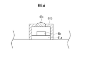
図6に示すように、拡散カバー61bは、第1枠装飾LED8b-1~第11枠装飾LED8b-11から照射された光を拡散して前方に透過するものであり、第1枠装飾LED8b-1~第11枠装飾LED8b-11に対応したそれぞれの位置には、光拡散部61cが形成されている。光拡散部61cは、それぞれ対応したLEDからの光を拡散する。 As shown in FIG. 6, the diffusion cover 61b diffuses the light emitted from the first frame decorative LED 8b-1 to the eleventh frame decorative LED 8b-11 and transmits it forward, and the first frame decorative LED 8b- A light diffusing portion 61c is formed at each position corresponding to the 1st to 11th frame decorative LEDs 8b-11. The light diffusing unit 61c diffuses the light from the corresponding LEDs.

上枠装飾ユニット62は、枠装飾部8aの上側部を発光、点滅させるものであり、上枠装飾基板62aと、上枠装飾基板62aを覆う拡散カバー62bとを備える。上枠装飾基板62aには、第12枠装飾LED8b-12~第21枠装飾LED8b-21が実装されている。 The upper frame decorative unit 62 emits light and blinks the upper portion of the frame decorative portion 8a, and includes an upper frame decorative substrate 62a and a diffusion cover 62b that covers the upper frame decorative substrate 62a. The 12th frame decorative LED 8b-12 to the 21st frame decorative LED 8b-21 are mounted on the upper frame decorative substrate 62a.

拡散カバー62bは、第12枠装飾LED8b-12~第21枠装飾LED8b-21から照射された光を拡散して前方に透過するものであり、第12枠装飾LED8b-12~第21枠装飾LED8b-21に対応したそれぞれの位置には、光拡散部62cが形成されている。拡散カバー62b及び光拡散部62cは、拡散カバー61b及び光拡散部61cと同様に構成されており、光拡散部62cは、それぞれ対応したLEDからの光を拡散する。 The diffusion cover 62b diffuses the light emitted from the 12th frame decorative LED 8b-12 to the 21st frame decorative LED 8b-21 and transmits it forward, and the 12th frame decorative LED 8b-12 to the 21st frame decorative LED 8b. A light diffusing portion 62c is formed at each position corresponding to -21. The diffusion cover 62b and the light diffusion unit 62c are configured in the same manner as the diffusion cover 61b and the light diffusion unit 61c, and the light diffusion unit 62c diffuses the light from the corresponding LEDs.

右枠装飾ユニット63は、枠装飾部8aの右側部を発光、点滅させるものであり、右枠装飾基板63aと、右枠装飾基板63aを覆う拡散カバー63bとを備える。右枠装飾基板63aには、第22枠装飾LED8b-22~第30枠装飾LED8b-30が実装されている。 The right frame decoration unit 63 emits light and blinks the right side portion of the frame decoration portion 8a, and includes a right frame decoration substrate 63a and a diffusion cover 63b that covers the right frame decoration substrate 63a. The 22nd frame decorative LED 8b-22 to the 30th frame decorative LED 8b-30 are mounted on the right frame decorative substrate 63a.

拡散カバー63bは、第22枠装飾LED8b-22~第30枠装飾LED8b-30から照射された光を拡散して前方に透過するものであり、第22枠装飾LED8b-22~第30枠装飾LED8b-30に対応したそれぞれの位置には、光拡散部63cが形成されている。拡散カバー63b及び光拡散部63cは、拡散カバー61b及び光拡散部61cと同様に構成されており、光拡散部63cは、それぞれ対応したLEDからの光を拡散する。 The diffusion cover 63b diffuses the light emitted from the 22nd frame decorative LED 8b-22 to the 30th frame decorative LED 8b-30 and transmits it forward, and the 22nd frame decorative LED 8b-22 to the 30th frame decorative LED 8b. A light diffusing portion 63c is formed at each position corresponding to -30. The diffusion cover 63b and the light diffusion unit 63c are configured in the same manner as the diffusion cover 61b and the light diffusion unit 61c, and the light diffusion unit 63c diffuses the light from the corresponding LEDs.

なお、図5では、上述の第1枠装飾LED8b-1~第30枠装飾LED8b-30及び各枠装飾基板61a~63aを、実線で示した。 In FIG. 5, the above-mentioned first frame decorative LEDs 8b-1 to 30th frame decorative LEDs 8b-30 and the frame decorative substrates 61a to 63a are shown by solid lines.

図7は、パチンコ遊技機1の制御装置の構成を示すブロック図である。なお、図7では信号を中継する中継基板や、本発明に関係のない一部の部材の構成を省略した。 FIG. 7 is a block diagram showing the configuration of the control device of the pachinko gaming machine 1. In addition, in FIG. 7, the configuration of the relay board for relaying the signal and some members not related to the present invention is omitted.

この制御装置は、パチンコ遊技機1の動作を統括的に制御する主制御基板24と、主制御基板24からコマンドを受けて演出の制御をする演出制御基板25を中心に構成される。電源基板28は、主制御基板24を初めとした各基板に接続され、外部電源から交流電圧24Vを受けて直流電圧に変換し、各基板に供給する。 This control device is mainly composed of a main control board 24 that comprehensively controls the operation of the pachinko gaming machine 1 and an effect control board 25 that receives a command from the main control board 24 to control the effect. The power supply board 28 is connected to each board including the main control board 24, receives an AC voltage 24V from an external power source, converts it into a DC voltage, and supplies it to each board.

主制御基板24は、その内部に、主制御基板側CPU241と、ROM242と、RAM243とを備えている。主制御基板側CPU241は、いわゆるプロセッサ部であり、大当りを発生させるか否かの抽選処理、決定された変動パターンや停止図柄の情報から制御コマンドを作成し、演出制御基板25に送信する等の処理を行う。 The main control board 24 includes a main control board side CPU 241, a ROM 242, and a RAM 243 inside. The CPU 241 on the main control board side is a so-called processor unit, and is a lottery process for whether or not to generate a big hit, a control command is created from information on a determined fluctuation pattern and a stop symbol, and is transmitted to the staging control board 25. Perform processing.

ROM242は、一連の遊技機制御手順を記述した制御プログラムや制御データ等を格納した記憶部である。また、RAM243は、主制御基板側CPU241の処理で設定されたデータを一時記憶するワークエリアを備えた記憶部である。 The ROM 242 is a storage unit that stores a control program, control data, and the like that describe a series of gaming machine control procedures. Further, the RAM 243 is a storage unit provided with a work area for temporarily storing the data set by the processing of the CPU 241 on the main control board side.

主制御基板24には、RAMクリアスイッチ27、第1始動入賞口センサ38d、第2始動入賞口センサ38e、大入賞口センサ39a、始動ゲート通過センサ40b、一般入賞口センサ42aが接続され、各センサの検出信号を受信可能となっている。 The RAM clear switch 27, the first start winning opening sensor 38d, the second starting winning opening sensor 38e, the large winning opening sensor 39a, the starting gate passing sensor 40b, and the general winning opening sensor 42a are connected to the main control board 24, and each of them is connected. It is possible to receive the detection signal of the sensor.

なお、パチンコ遊技機1に磁石等を近づけた場合に、磁気を検出する磁気センサ、パチンコ遊技機1に対し発せられた強い電波を検出する電波センサ、及び、パチンコ遊技機1に対し与えられた強い振動を検出する振動センサ等を設けてもよい。 It was given to the magnetic sensor that detects magnetism when a magnet or the like is brought close to the pachinko game machine 1, the radio wave sensor that detects the strong radio wave emitted to the pachinko game machine 1, and the pachinko game machine 1. A vibration sensor or the like that detects strong vibration may be provided.

また、主制御基板24には、特別図柄表示装置43a及び普通図柄表示装置43bが接続され、主制御基板側CPU241が抽選処理により取得した乱数情報は、各図柄表示装置43a,43bに送信される。 Further, a special symbol display device 43a and a normal symbol display device 43b are connected to the main control board 24, and random number information acquired by the main control board side CPU 241 by lottery processing is transmitted to the symbol display devices 43a and 43b. ..

また、主制御基板24には、パチンコ遊技機1の外部へ接続する端子を備えた外部端子基板21が接続されている。遊技における大当り、入賞数、ゲーム数等の各種情報は、主制御基板24から外部端子基板21を介してホールコンピュータに送信される。 Further, an external terminal board 21 having a terminal for connecting to the outside of the pachinko gaming machine 1 is connected to the main control board 24. Various information such as big hits, winning numbers, and game numbers in the game is transmitted from the main control board 24 to the hall computer via the external terminal board 21.

さらに、主制御基板24には、払出制御基板29が接続されている。払出制御基板29には、下貯留皿満杯センサ12c及び扉開放センサ20が接続されているため、これらのセンサが異常を検出すると、検出信号は払出制御基板29から主制御基板24に送信される。なお、払出制御基板29には、遊技球払出装置19と、発射制御基板30(さらに発射装置10aと接続)が接続している。 Further, a payout control board 29 is connected to the main control board 24. Since the lower storage dish full sensor 12c and the door open sensor 20 are connected to the payout control board 29, when these sensors detect an abnormality, the detection signal is transmitted from the payout control board 29 to the main control board 24. .. The game ball payout device 19 and the launch control board 30 (further connected to the launch device 10a) are connected to the payout control board 29.

次に、演出制御基板25は、その内部に、演出制御基板側CPU251と、ROM252と、RAM253とを備えている。演出制御基板側CPU251は、いわゆるプロセッサ部であり、主制御基板24から送信された制御コマンドを受信し、その制御コマンドに基づいた各種演出を制御する処理を行う。 Next, the staging control board 25 includes a staging control board side CPU 251, a ROM 252, and a RAM 253 inside. The effect control board side CPU 251 is a so-called processor unit, receives a control command transmitted from the main control board 24, and performs a process of controlling various effects based on the control command.

ROM252は、一連の演出制御手順を記述した制御プログラムや演出データ等を格納した記憶部である。また、RAM253は、演出制御基板側CPU251の処理で設定されたデータを一時記憶するワークエリアを備えた記憶部である。 The ROM 252 is a storage unit that stores a control program, effect data, and the like that describe a series of effect control procedures. Further, the RAM 253 is a storage unit provided with a work area for temporarily storing the data set by the processing of the CPU 251 on the staging control board side.

また、図8に示すように、演出制御基板25には、スピーカ7、第1枠装飾LED8b-1~第30枠装飾LED8b-30から構成される枠装飾LED8b、第1センター装飾LED51b~51d、第2センター装飾LED52b~52d、第3センター装飾LED53b~53d、第4センター装飾LED54b~54d、第1~第4左装飾LED56b~56e、第1~第4右装飾LED57b~57e、第1~第5下装飾LED58b~58f、及び第1~第5上装飾LED59b~59fが接続されている。演出制御基板25の演出制御基板側CPU251は、スピーカ7の効果音や各LED等の発光動作を制御し、演出効果を高めている。演出制御基板側CPU251は、本発明の「発光制御手段」に相当する。 Further, as shown in FIG. 8, the staging control board 25 includes a speaker 7, a frame decoration LED 8b composed of a first frame decoration LED 8b-1 to a thirty frame decoration LED 8b-30, and a first center decoration LED 51b to 51d. 2nd center decoration LED 52b to 52d, 3rd center decoration LED 53b to 53d, 4th center decoration LED 54b to 54d, 1st to 4th left decoration LEDs 56b to 56e, 1st to 4th right decoration LEDs 57b to 57e, 1st to 1st 5 The lower decorative speakers 58b to 58f and the first to fifth upper decorative LEDs 59b to 59f are connected. The effect control board side CPU 251 of the effect control board 25 controls the sound effect of the speaker 7 and the light emission operation of each LED and the like to enhance the effect. The CPU 251 on the staging control board side corresponds to the "light emission control means" of the present invention.

また、演出制御基板25には、操作ボタン13、及び方向キー部14が接続されている。演出制御基板25は、操作ボタン13の有効期間に、操作ボタン13に対して内蔵ランプを点灯させる信号を送信する。そして、有効期間に遊技者が操作ボタン13を押下することで、検知信号が演出制御基板25に送信され、液晶表示装置36に表示された演出等が変化する。 Further, the operation button 13 and the direction key unit 14 are connected to the staging control board 25. The staging control board 25 transmits a signal for lighting the built-in lamp to the operation button 13 during the valid period of the operation button 13. Then, when the player presses the operation button 13 during the valid period, the detection signal is transmitted to the effect control board 25, and the effect displayed on the liquid crystal display device 36 changes.

方向キー部14は、上方向キー、右方向キー、下方向キー及び左方向キーで構成されている(図1参照)。方向キー部14についても、操作された場合に、その検知信号が演出制御基板25に送信される。 The direction key unit 14 is composed of an up direction key, a right direction key, a down direction key, and a left direction key (see FIG. 1). When the direction key unit 14 is also operated, the detection signal is transmitted to the staging control board 25.

さらに、演出制御基板25には、液晶制御基板26が接続されている。液晶制御基板26は、演出制御基板25からコマンドを受けて液晶表示装置36の表示制御を行うものである。 Further, the liquid crystal control board 26 is connected to the staging control board 25. The liquid crystal control board 26 receives a command from the staging control board 25 to control the display of the liquid crystal display device 36.

液晶制御基板26は、その内部に、液晶制御CPU261と、液晶制御ROM262と、液晶制御RAM263と、映像表示プロセッサVDP264と、画像データROM265と、VRAM266とを備えている。 The liquid crystal control board 26 includes a liquid crystal control CPU 261, a liquid crystal control ROM 262, a liquid crystal control RAM 263, a video display processor VDP 264, an image data ROM 265, and a VRAM 266.

液晶制御CPU261は、いわゆるプロセッサ部であり、演出制御基板25から受信した液晶制御コマンドに基づいて表示制御を行うために必要な液晶制御データを生成する。また、そのデータを映像表示プロセッサVDP264に出力する。 The liquid crystal control CPU 261 is a so-called processor unit, and generates liquid crystal control data necessary for performing display control based on the liquid crystal control command received from the staging control board 25. Further, the data is output to the video display processor VDP264.

液晶制御ROM262は、液晶制御CPU261の動作手順を記述したプログラムを格納した記憶部であり、液晶制御RAM263は、ワークエリアやバッファメモリとして機能する記憶部である。 The liquid crystal control ROM 262 is a storage unit that stores a program that describes the operation procedure of the liquid crystal control CPU 261, and the liquid crystal control RAM 263 is a storage unit that functions as a work area or a buffer memory.

映像表示プロセッサVDP264は、液晶表示装置36に表示する画像データの画像処理を行うプロセッサである。また、画像データROM265は、映像表示プロセッサVDP264が画像処理を行うために必要な画像データを格納した記憶部であり、VRAM266は、映像表示プロセッサVDP264が画像処理した画像データを一時記憶する記憶部である。 The video display processor VDP264 is a processor that performs image processing of image data to be displayed on the liquid crystal display device 36. Further, the image data ROM 265 is a storage unit that stores image data necessary for the image display processor VDP 264 to perform image processing, and the VRAM 266 is a storage unit that temporarily stores the image data processed by the video display processor VDP 264. be.

上記の構成により液晶制御基板26は、演出制御基板25から送信された液晶制御コマンドに基づき画像処理を行い、液晶表示装置36に演出画像や動画を表示している。 With the above configuration, the liquid crystal control board 26 performs image processing based on the liquid crystal control command transmitted from the effect control board 25, and displays the effect image and the moving image on the liquid crystal display device 36.

次に、図9を参照して、パチンコ遊技機1の大当り種別と特別遊技(大当り遊技)の終了時に設定される各種フラグについて説明する。 Next, with reference to FIG. 9, the jackpot type of the pachinko gaming machine 1 and various flags set at the end of the special game (big hit game) will be described.

パチンコ遊技機1には、例えば「1」~「9」の装飾図柄のうち、確変図柄(例えば、「3」と「7」の装飾図柄)による大当りと、非確変図柄(例えば、「3」、「7」以外の装飾図柄)による大当りの2種類がある。各図柄は3列(左列、中央列、右列)で変動表示され、3列で同じ図柄が揃う(例えば「777」)と大当りとなる。変動表示する3列の図柄は、左列、右列、中央列の順で停止し、左右列が同じ図柄で揃って停止し、中央列の図柄が変動表示している状態がリーチとなる。 For the pachinko gaming machine 1, for example, among the decorative symbols of "1" to "9", a jackpot with a probabilistic symbol (for example, a decorative symbol of "3" and "7") and a non-probable variable symbol (for example, "3") , Decorative designs other than "7") There are two types of jackpots. Each symbol is variablely displayed in three columns (left column, center column, right column), and when the same symbols are aligned in the three columns (for example, "777"), a big hit is obtained. The three columns of symbols to be variablely displayed are stopped in the order of the left column, the right column, and the center column, the left and right columns are all stopped at the same symbol, and the state in which the symbols in the center column are variablely displayed is the reach.

パチンコ遊技機1では、通常モード、時短モード、確率変動モードで遊技が行われる。通常モードは、低確率(例えば、1/100で「大当り」)での抽選となる。時短モードは、通常モードと同じ抽選確率ではあるが、図柄の変動表示の時間を短縮した遊技状態であり、通常モードより普通電動役物の開閉部材が頻繁に開放され(電チューサポート有り状態)、遊技球が始動入賞し易い。確率変動モードは、通常モード及び時短モードよりも高確率(例えば、1/10で「大当り」)での抽選であり、電チューサポート有り状態である。 In the pachinko gaming machine 1, a game is performed in a normal mode, a time saving mode, and a probability fluctuation mode. The normal mode is a lottery with a low probability (for example, "big hit" at 1/100). The time saving mode has the same lottery probability as the normal mode, but it is a gaming state in which the time for displaying the fluctuation of the symbol is shortened. , The game ball is easy to start and win. The probability fluctuation mode is a lottery with a higher probability (for example, "big hit" at 1/10) than the normal mode and the time saving mode, and is in a state with electric chew support.

確変図柄大当りによる特別遊技は、例えば、全15ラウンドで構成され、非確変図柄大当りによる特別遊技は、全15ラウンドの場合もあるが、基本的にこれより少ないラウンドで構成される。確変図柄大当りの終了後には、遊技状態が確率変動モードとなる。確率変動モードは、50回の遊技が行われると終了する。なお、確率変動モードを、次回の大当りまで継続するモードとしてもよい。 The special game by the probabilistic symbol jackpot is composed of, for example, all 15 rounds, and the special game by the non-probability symbol jackpot is composed of all 15 rounds, but basically it is composed of less rounds. After the end of the probabilistic symbol jackpot, the game state becomes the probability fluctuation mode. The probability fluctuation mode ends when 50 games are played. The probability fluctuation mode may be a mode that continues until the next big hit.

次に、非確変図柄大当りについて、確変図柄大当りと異なる部分を中心に説明する。非確変図柄大当りによる特別遊技は、例えば、全10ラウンドで構成される。また、その終了後には、遊技状態が時短モードとなる。本実施形態の時短モードは、30回の遊技が行われると終了する。 Next, the non-probability symbol jackpot will be described focusing on the part different from the probabilistic symbol jackpot. The special game by the non-probability symbol jackpot consists of, for example, all 10 rounds. In addition, after the end, the game state becomes the reduced working hours mode. The time saving mode of this embodiment ends when 30 games are played.

次に、確変図柄大当り、非確変図柄大当りいずれの特別遊技の終了後に設定される各種フラグについて説明する。図9に示すように、普電開放延長状態フラグ、普図時短移行状態フラグ、普図確率変動移行状態フラグ、特図時短移行状態フラグに「5AH」がセットされる。「5AH」とは、フラグがオンの意味である。 Next, various flags set after the end of either the probabilistic symbol jackpot or the non-probabilistic symbol jackpot will be described. As shown in FIG. 9, "5AH" is set in the normal power release extension state flag, the normal figure time reduction transition state flag, the normal figure probability fluctuation transition state flag, and the special figure time reduction transition state flag. "5AH" means that the flag is on.

確変図柄大当りの場合は、特図確率変動移行状態フラグに「5AH」がセットされる。一方、非確変図柄大当りの場合、特別遊技の終了後に確率変動モードに移行しないので、特図確率変動移行状態フラグに「00H」がセットされる。「00H」とは、フラグがオフの意味である。 In the case of a probabilistic symbol jackpot, "5AH" is set in the special figure probability fluctuation transition state flag. On the other hand, in the case of a non-probability variation symbol jackpot, since the mode does not shift to the probability fluctuation mode after the end of the special game, "00H" is set in the special symbol probability fluctuation transition state flag. "00H" means that the flag is off.

なお、非確変図柄大当りの場合でも、電チューサポート有り状態となる。従って、上述の普図確率変動移行状態フラグは、確変図柄、非確変図柄に関わらず、「5AH」がセットされる。 Even in the case of a non-probability variation symbol jackpot, the electric chew support is available. Therefore, the above-mentioned normal figure probability fluctuation transition state flag is set to "5AH" regardless of the probable variation symbol or the non-probability variation symbol.

また、確変図柄大当りの場合は、特図時短回数カウンタ及び特図確率変動回数カウンタに「50」がセットされ、非確変図柄大当りの場合は、特図時短回数カウンタに「30」がセットされ、特図確率変動回数カウンタに「0」がセットされる。ここで、「50」、「30」とは、50回、30回の遊技を意味し、「0」は、特図確率変動での遊技が0回、すなわち、行われないことを意味する。 Further, in the case of a probabilistic symbol jackpot, "50" is set in the special figure time reduction counter and the special figure probability fluctuation counter, and in the case of a non-probability variation symbol jackpot, "30" is set in the special symbol time reduction counter. "0" is set in the special figure probability fluctuation counter. Here, "50" and "30" mean 50 times and 30 times of games, and "0" means that the games in the special figure probability fluctuation are 0 times, that is, not played.

特図時短回数カウンタ、特図確率変動回数カウンタの値は、変更することができる。例えば、確変図柄大当りの場合、特図時短回数カウンタ及び特図確率変動回数カウンタに「100」をセットすると、特別遊技の終了後、100回の確率変動モードに移行する。 The values of the special figure time reduction counter and the special figure probability fluctuation counter can be changed. For example, in the case of a probabilistic symbol jackpot, if "100" is set in the special figure time reduction counter and the special figure probability fluctuation counter, the mode shifts to the probability fluctuation mode of 100 times after the end of the special game.

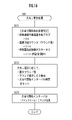
次に、図10を参照して、主制御側で行われる遊技管理処理について説明する。以下で説明する遊技管理処理は、電源投入処理が正常に終了した場合に、主制御側のメインループに対して実行されるタイマ割込処理である。 Next, the game management process performed on the main control side will be described with reference to FIG. The game management process described below is a timer interrupt process executed for the main loop on the main control side when the power-on process ends normally.

まず、主制御基板24は、タイマ管理処理を行う(ステップS10)。パチンコ遊技機1には、特別図柄役物動作タイマ等の複数のタイマが用意されており、それぞれ遊技に関する時間を計時している。 First, the main control board 24 performs a timer management process (step S10). The pachinko gaming machine 1 is provided with a plurality of timers such as a special symbol accessory operation timer, each of which measures the time related to the game.

主制御基板24は、処理状態に応じて各種タイマを更新(タイマを減算)していくことで、多数のタイマを管理する。その後、ステップS20に進む。 The main control board 24 manages a large number of timers by updating (subtracting timers) various timers according to the processing state. After that, the process proceeds to step S20.

ステップS20では、主制御基板24は、賞球管理処理を行う。これは、遊技盤4の遊技領域を流下する遊技球が、第1,第2特別図柄始動口37a,37bや一般入賞口42に入賞した場合に行われる処理である。例えば、一般入賞口42の内部にある一般入賞口センサ42aが遊技球を検知し、球検知信号を主制御基板24に送信する。 In step S20, the main control board 24 performs a prize ball management process. This is a process performed when a game ball flowing down the game area of the game board 4 wins a prize in the first and second special symbol start openings 37a and 37b and the general winning opening 42. For example, the general winning opening sensor 42a inside the general winning opening 42 detects a game ball and transmits a ball detection signal to the main control board 24.

主制御基板24は、上記信号を受信すると、払出制御基板29(更には、遊技球払出装置19)に向けて所定個数の賞球の払出しを行うための制御信号を送信する。遊技球払出装置19は、上記制御信号を受信した後に、上貯留皿11(上貯留皿11が満杯である場合には、下貯留皿12)に所定個数の賞球を払出す。その後、ステップS30に進む。 Upon receiving the above signal, the main control board 24 transmits a control signal for paying out a predetermined number of prize balls to the payout control board 29 (further, the game ball payout device 19). After receiving the control signal, the game ball payout device 19 pays out a predetermined number of prize balls to the upper storage plate 11 (or the lower storage plate 12 when the upper storage plate 11 is full). Then, the process proceeds to step S30.

ステップS30では、主制御基板24は、普通図柄管理処理を行う。これは、遊技盤4の遊技領域を流下する遊技球が、普通図柄用始動ゲート40aを通過した場合に行われる処理である。具体的には、普通図柄用始動ゲート40aの内部にある始動ゲート通過センサ40bがゲートを通過した遊技球を検知して、球検知信号を主制御基板24に送信する。 In step S30, the main control board 24 normally performs a symbol management process. This is a process performed when the game ball flowing down the game area of the game board 4 passes through the normal symbol start gate 40a. Specifically, the start gate passage sensor 40b inside the normal symbol start gate 40a detects a game ball that has passed through the gate, and transmits a ball detection signal to the main control board 24.

主制御基板24は、上記信号を受信すると、普通図柄の乱数値を取得する。この抽選した乱数値は最大4個まで記憶可能であり、記憶した順に上記乱数値の当否抽選を行う。 When the main control board 24 receives the above signal, it acquires a random value of a normal symbol. Up to four random numbers can be stored in this lottery, and the winning / failing lottery of the above random values is performed in the order in which they are stored.

また、主制御基板24は、普通図柄表示装置43bに制御信号を送信する。普通図柄表示装置43bでは、LEDの点滅による普通図柄の変動が行われ、普通図柄は、所定時間の経過後、抽選結果に応じて当り又は外れの態様を表示して停止する。その後、ステップS40に進む。 Further, the main control board 24 transmits a control signal to the normal symbol display device 43b. In the normal symbol display device 43b, the normal symbol is changed by blinking the LED, and after a predetermined time elapses, the normal symbol displays a hit or miss mode according to the lottery result and stops. Then, the process proceeds to step S40.

ステップS40では、主制御基板24は、普通電動役物管理処理を行う。これは、普通図柄の抽選結果により普通電動役物の動作を制御する処理である。普通図柄管理処理(ステップS30)にて、普通図柄が当り態様で停止した場合には、主制御基板24は、普通電動役物用ソレノイドに制御信号を送信し、所定時間、第2特別図柄始動口37bの開閉部材を開放する。 In step S40, the main control board 24 normally performs an electric accessory management process. This is a process of controlling the operation of an ordinary electric accessory based on the lottery result of an ordinary symbol. In the normal symbol management process (step S30), when the normal symbol stops in a hitting manner, the main control board 24 transmits a control signal to the solenoid for the normal electric accessory, and starts the second special symbol for a predetermined time. The opening / closing member of the mouth 37b is opened.

主制御基板24は、上記所定時間が経過した場合、又は所定時間経過前に第2特別図柄始動口37bに予め定められた上限数の遊技球が入賞した場合に、上記開閉部材を閉鎖するための制御信号を普通電動役物用ソレノイドに送信する。これにより、上記開閉部材は閉鎖する。その後、ステップS50に進む。 The main control board 24 closes the opening / closing member when the predetermined time elapses or when a predetermined upper limit number of game balls wins in the second special symbol start port 37b before the elapse of the predetermined time. The control signal of is transmitted to the solenoid for ordinary electric accessory. As a result, the opening / closing member is closed. Then, the process proceeds to step S50.

なお、普通図柄管理処理(ステップS30)にて、普通図柄が外れ態様で停止した場合には、上記開閉部材を開放することはなく、主制御基板24は、何もせず普通電動役物遊技処理を終了する。 In the normal symbol management process (step S30), when the normal symbol is stopped in a detached manner, the opening / closing member is not opened, and the main control board 24 does nothing and performs a normal electric accessory game process. To finish.

ステップS50では、主制御基板24は、特別図柄管理処理を行う。これは、遊技盤4の遊技領域を流下する遊技球が、第1特別図柄始動口37a又は第2特別図柄始動口37bに入賞した場合に行われる処理である。 In step S50, the main control board 24 performs a special symbol management process. This is a process performed when a game ball flowing down the game area of the game board 4 wins a prize in the first special symbol start port 37a or the second special symbol start port 37b.

詳細は後述するが、始動入賞口センサ37c,37dが遊技球を検出すると、始動入賞口センサ37c,37dは、球検出信号を主制御基板24に送信し、主制御基板24は、球検出信号を受けて、例えば600個の乱数値の中から1個の乱数値を取得し(特別図柄の抽選)、この取得した乱数値に対する演出態様を決定する。 Although the details will be described later, when the start winning opening sensors 37c and 37d detect the game ball, the starting winning opening sensors 37c and 37d transmit the ball detection signal to the main control board 24, and the main control board 24 transmits the ball detection signal. In response to this, for example, one random value is acquired from among 600 random values (lottery of a special symbol), and an effect mode for the acquired random value is determined.

主制御基板24は、特別図柄表示装置43aに演出コマンドを送信する。特別図柄表示装置43aでは、7セグメントLEDによる特別図柄の変動が行われ、特別図柄が所定時間の経過後に抽選結果に応じて当り又は外れの態様で停止する。また、特別図柄の変動は、液晶表示装置36においても遊技者に確実に認識可能な装飾図柄で表示される。その後、ステップS60に進む。 The main control board 24 transmits an effect command to the special symbol display device 43a. In the special symbol display device 43a, the special symbol is changed by the 7-segment LED, and the special symbol is stopped in a hit or miss manner according to the lottery result after a lapse of a predetermined time. Further, the variation of the special symbol is displayed as a decorative symbol that can be reliably recognized by the player even on the liquid crystal display device 36. Then, the process proceeds to step S60.

最後に、ステップS60では、主制御基板24は、特別電動役物管理処理を行う。これは、特別図柄の抽選結果により大入賞装置39(以下、特別電動役物とも称する)の動作を制御する処理である。 Finally, in step S60, the main control board 24 performs a special electric accessory management process. This is a process of controlling the operation of the large winning device 39 (hereinafter, also referred to as a special electric accessory) based on the lottery result of the special symbol.

詳細は後述するが、特別図柄が当り態様で停止した場合には、いわゆる大当りとなり、所定ラウンド数の特別遊技が遊技者に付与される。特別図柄管理処理(ステップS50)にて、特別図柄が外れ態様で停止した場合には、直ちに特別電動役物管理処理が終了となる。特別電動役物管理処理が終了すると、遊技管理処理も終了となる。 The details will be described later, but when the special symbol stops in the hit mode, it becomes a so-called big hit, and a predetermined number of special games are given to the player. In the special symbol management process (step S50), when the special symbol is stopped in a detached manner, the special electric accessory management process is immediately terminated. When the special electric accessory management process is completed, the game management process is also completed.

次に、図11を参照して、遊技管理処理の中で行われる特別図柄管理処理について説明する。特別図柄管理処理(図10:ステップS50)では、主制御基板24は、後述する特別図柄動作ステータス(変動待機中、変動中)を判定し、それぞれの処理を管理する。 Next, with reference to FIG. 11, the special symbol management process performed in the game management process will be described. In the special symbol management process (FIG. 10: step S50), the main control board 24 determines the special symbol operation status (during standby for change, during change), which will be described later, and manages each process.

まず、主制御基板24は、始動口チェック処理1を行う(ステップS51)。これは、第1特別図柄始動口37aへの遊技球の入賞の有無を判断する。第1特別図柄始動口37aへの遊技球の入賞があった場合には、主制御基板側CPU241は、第1始動入賞口センサ38dから送られる球検出信号に基づいて、200個の乱数値の中から1個の乱数値を取得する。 First, the main control board 24 performs the start port check process 1 (step S51). This determines whether or not a game ball has won a prize in the first special symbol start opening 37a. When a game ball is won in the first special symbol start opening 37a, the CPU 241 on the main control board side has 200 random values based on the ball detection signal sent from the first start winning opening sensor 38d. Get one random value from the inside.

ROM242には、演出情報テーブルが格納されている。この演出情報テーブルは、600個の乱数値それぞれに対応付けられた第1~第600演出態様を有する。主制御基板側CPU241は、取得した乱数値に対応した演出態様を、演出情報テーブルから読み込む。また、主制御基板側CPU241は、乱数値に基づいて大当り判定フラグを取得して、ワークエリアへ格納する処理も行う。 The effect information table is stored in the ROM 242. This effect information table has first to 600 effect modes associated with each of the 600 random values. The main control board side CPU 241 reads the effect mode corresponding to the acquired random number value from the effect information table. Further, the CPU 241 on the main control board side also performs a process of acquiring a jackpot determination flag based on a random number value and storing it in the work area.

特別図柄の変動表示中に、遊技球が第1特別図柄始動口37aに入賞すると、主制御基板側CPU241は、乱数値(抽選結果)、演出態様を含む演出コマンドを、RAM243の保留記憶エリアに記憶する。また、主制御基板側CPU241は、演出制御基板25を介して液晶制御基板26の液晶制御CPU261に演出コマンドを送る。液晶制御CPU261は、この演出コマンドを、保留情報として液晶制御RAM263に記憶する。液晶制御RAM263に記憶される保留情報は、例えば最大4個である。 When the game ball wins the first special symbol start port 37a during the variable display of the special symbol, the CPU 241 on the main control board side sends an effect command including a random number value (lottery result) and an effect mode to the hold storage area of the RAM 243. Remember. Further, the main control board side CPU 241 sends an effect command to the liquid crystal control CPU 261 of the liquid crystal control board 26 via the effect control board 25. The liquid crystal control CPU 261 stores this effect command in the liquid crystal control RAM 263 as hold information. The maximum number of reserved information stored in the liquid crystal control RAM 263 is, for example, four.

ステップS52では、主制御基板24は、始動口チェック処理2を行う。第2特別図柄始動口37bへの遊技球の入賞の有無を判断し、始動口チェック処理1と同様の処理を行う。その後、ステップS53に進む。 In step S52, the main control board 24 performs the start port check process 2. It is determined whether or not the game ball has won a prize in the second special symbol start opening 37b, and the same process as in the start opening check process 1 is performed. After that, the process proceeds to step S53.

次に、主制御基板24は、条件装置作動フラグが5AHか否かを判定する(ステップS53)。条件装置とは、大当り発生時に大当りを継続する条件が成立した場合に作動する装置であり、条件装置作動フラグがオンしたか否かの判定となる。条件装置作動フラグがオンである場合には、「YES」の判定となり、ステップS58に進む。 Next, the main control board 24 determines whether or not the condition device operation flag is 5AH (step S53). The condition device is a device that operates when a condition for continuing the big hit is satisfied when a big hit occurs, and determines whether or not the condition device operation flag is turned on. If the condition device operation flag is on, the determination is "YES", and the process proceeds to step S58.

一方、条件装置作動フラグがオンしていない場合には、「NO」の判定となり、ステップS54に進む。すなわち、ステップS54~S57は、大当りが発生していない通常遊技モードの場合の処理となる。 On the other hand, if the condition device operation flag is not turned on, the determination is "NO" and the process proceeds to step S54. That is, steps S54 to S57 are processes in the case of the normal game mode in which the big hit does not occur.

ステップS53の判定が「NO」である場合、主制御基板24は、特別図柄動作ステータス判定を行う(ステップS54)。特別図柄動作ステータス(以下、特図動作ステータスともいう)が「00H」、「01H」に設定されている場合は、特別図柄が「変動待機中」であるので、ステップS55に進む。 When the determination in step S53 is "NO", the main control board 24 determines the special symbol operation status (step S54). When the special symbol operation status (hereinafter, also referred to as the special symbol operation status) is set to "00H" or "01H", the special symbol is "waiting for change", so the process proceeds to step S55.

また、特図動作ステータスが「02H」に設定されている場合は、特別図柄が「変動中」であるので、ステップS56に進む。さらに、特図動作ステータスが「03H」に設定されている場合は、特別図柄の「確認時間中」であるので、ステップS57に進む。以下、各特図動作ステータスにおける処理について説明する。 Further, when the special symbol operation status is set to "02H", the special symbol is "changing", so the process proceeds to step S56. Further, when the special symbol operation status is set to "03H", the special symbol is "during confirmation time", so the process proceeds to step S57. Hereinafter, the processing in each special figure operation status will be described.

まず、図12A、図12Bを参照して、特別図柄管理処理の中で行われる特別図柄変動開始処理(ステップS55)について説明する。 First, the special symbol change start process (step S55) performed in the special symbol management process will be described with reference to FIGS. 12A and 12B.

まず、図12Aにおいて、主制御基板側CPU241は、特図保留球数が0であるか否かを判定する(ステップS71)。特図の保留球数が0である場合には、「YES」の判定となり、ステップS72に進む。一方、特図の保留球数が0でない場合には、「NO」の判定となり、ステップS76に進む(図12B参照)。 First, in FIG. 12A, the CPU 241 on the main control board side determines whether or not the number of reserved balls in the special figure is 0 (step S71). If the number of reserved balls in the special figure is 0, the determination is "YES" and the process proceeds to step S72. On the other hand, if the number of reserved balls in the special figure is not 0, the determination is "NO" and the process proceeds to step S76 (see FIG. 12B).

ステップS72では、第1特別図柄始動口37aまたは第2特別図柄始動口37bへの遊技球の入賞の有無を判定する。ステップS72の判定が「YES」である場合には、乱数値を取得し、ステップS79に進む。 In step S72, it is determined whether or not the game ball has won a prize in the first special symbol start opening 37a or the second special symbol start opening 37b. If the determination in step S72 is "YES", a random number value is acquired and the process proceeds to step S79.

ステップS72の判定が「NO」である場合には、主制御基板24は、特図動作ステータスが00Hであるか否かを判定する(ステップS73)。後述するが、特別図柄確認時間中処理(図11:ステップS57)が実行された直後は、特図動作ステータスとして「01H」がセットされている。 When the determination in step S72 is "NO", the main control board 24 determines whether or not the special figure operation status is 00H (step S73). As will be described later, immediately after the special symbol confirmation time process (FIG. 11: step S57) is executed, "01H" is set as the special symbol operation status.

特図動作ステータスが「00H」である場合には、「YES」の判定となり、特別図柄変動開始処理を終了する。一方、特図動作ステータスが「00H」でない場合(「01H」である場合)には、「NO」の判定となり、ステップS74に進む。 If the special symbol operation status is "00H", the determination is "YES" and the special symbol change start processing is terminated. On the other hand, if the special figure operation status is not "00H" (when it is "01H"), the determination is "NO" and the process proceeds to step S74.

ステップS74では、主制御基板24は、客待ちデモコマンドを送信する。「客待ちデモコマンド」は、特図の保留球数が0、且つ、特図動作ステータスが「01H」の場合に、主制御基板24から演出制御基板25に向けて送信される。その後、ステップS75に進む。 In step S74, the main control board 24 transmits a customer waiting demo command. The "customer waiting demo command" is transmitted from the main control board 24 to the staging control board 25 when the number of reserved balls of the special figure is 0 and the special figure operation status is "01H". Then, the process proceeds to step S75.

ステップS75では、主制御基板24は、特図動作ステータスに00Hをセットする。このセットにより特別図柄変動開始処理は終了となるが、これ以後、特別図柄変動開始処理では、保留情報や始動口入賞が発生しない限り、ステップS73の判定で「YES」となる処理を繰り返す。 In step S75, the main control board 24 sets 00H to the special figure operation status. The special symbol change start process ends with this set, but thereafter, in the special symbol change start process, the process of "YES" in the determination of step S73 is repeated unless the hold information or the start opening winning is generated.

ステップS71の判定が「NO」である場合、主制御基板24は、特図の保留球数を1減算する(図12B:ステップS76)。その後、ステップS77に進む。 When the determination in step S71 is "NO", the main control board 24 subtracts 1 from the number of reserved balls in the special figure (FIG. 12B: step S76). Then, the process proceeds to step S77.

ステップS77では、主制御基板24は、演出制御基板25に向けて保留減算コマンドを送信する。これにより、特別図柄表示装置43a(右側の7セグメントLED)の保留表示及び液晶表示装置36に表示された保留表示が1減算される。その後、ステップS78に進む。 In step S77, the main control board 24 transmits a hold subtraction command to the staging control board 25. As a result, the hold display of the special symbol display device 43a (7-segment LED on the right side) and the hold display displayed on the liquid crystal display device 36 are subtracted by 1. Then, the process proceeds to step S78.

ステップS78では、主制御基板24は、保留記憶エリアをシフトする。最大保留数と同数ある保留記憶エリア1~4は、保留球数の減算に伴い1だけシフトする。このとき、最新の保留情報が記憶される保留記憶エリア4については0をセットする。その後、ステップS79に進む。 In step S78, the main control board 24 shifts the hold storage area. The reserved storage areas 1 to 4, which have the same number as the maximum reserved number, are shifted by 1 as the number of reserved balls is subtracted. At this time, 0 is set for the hold storage area 4 in which the latest hold information is stored. Then, the process proceeds to step S79.

ステップS79では、主制御基板側CPU241は、特別電動役物作動判定用乱数判定処理を行う。これは、取得した乱数値に基づいた特図の当り判定処理である。また、大当り判定フラグをワークエリアへ格納する処理も行う。 In step S79, the main control board side CPU 241 performs a random number determination process for determining the operation of the special electric accessory. This is a hit determination process of the special figure based on the acquired random number value. In addition, the process of storing the jackpot determination flag in the work area is also performed.

本実施形態では、通常モード及び時短モードと、確率変動モードとで大当り確率が異なるため、「大当り」となる乱数値が異なる。通常モード及び時短モードでは、600個の乱数値のうち、乱数値595~600が「大当り」となる乱数値であり、乱数値595~597は、非確変図柄大当りとなり、乱数値598~600は、確変図柄大当りとなる。なお、乱数値581~600が、リーチとなる乱数値である。 In the present embodiment, since the jackpot probability is different between the normal mode and the time saving mode and the probability fluctuation mode, the random number value that becomes the “big hit” is different. In the normal mode and the time saving mode, among the 600 random numbers, the random numbers 595 to 600 are random values that are "big hits", the random numbers 595 to 597 are non-probable variable symbol big hits, and the random numbers 598 to 600 are. , It will be a big hit with a probabilistic symbol. The random number values 581 to 600 are random value values to reach.

確率変動モードでは、大当り確率が通常モード(1/100で大当り)の10倍となる(1/10で大当り)ため、乱数値541~600が「大当り」となる乱数値であり、乱数値541~570は非確変図柄大当りとなり、乱数値571~600は確変図柄大当りとなる。なお、乱数値の数や、「大当り」となる乱数値等は、適宜変更可能である。 In the probability fluctuation mode, the jackpot probability is 10 times that of the normal mode (1/10 is a jackpot) (1/10 is a jackpot), so the random numbers 541 to 600 are random values that are "big hits", and the random number value 541. ~ 570 is a non-probability variation symbol jackpot, and random numbers 571 to 600 are probability variation symbol jackpots. The number of random numbers, the random value that becomes a "big hit", and the like can be changed as appropriate.

ステップS80では、主制御基板24は、遊技状態移行準備処理を行う。ここでは、大当り判定フラグがオンの場合に、大当り種別に応じた遊技状態移行テーブルを選択し、これを参照して各種バッファに値を格納する。その後、ステップS81に進む。 In step S80, the main control board 24 performs a game state transition preparation process. Here, when the big hit determination flag is on, the game state transition table corresponding to the big hit type is selected, and the values are stored in various buffers with reference to this. Then, the process proceeds to step S81.

ステップS81では、主制御基板24は、特図の変動中フラグを5AHにセットする。その後、ステップS82に進む。 In step S81, the main control board 24 sets the changing flag of the special figure to 5AH. Then, the process proceeds to step S82.

ステップS82では、主制御基板側CPU241は、取得した乱数値に対応した演出態様を、演出情報テーブル246から読み込み、乱数値及び演出態様を含む演出コマンドを特別図柄表示装置43aに送り、演出コマンドまたは演出実行コマンドを演出制御基板25に送る。主制御基板側CPU241は、保留情報が記憶されていない場合には演出コマンドを、保留情報が記憶されている場合には演出実行コマンドを、演出制御基板25に送る。その後、ステップS83に進む。 In step S82, the main control board side CPU 241 reads the effect mode corresponding to the acquired random value value from the effect information table 246, sends the effect command including the random value and the effect mode to the special symbol display device 43a, and sends the effect command or the effect command. The effect execution command is sent to the effect control board 25. The main control board side CPU 241 sends an effect command when the hold information is not stored, and sends an effect execution command to the effect control board 25 when the hold information is stored. Then, the process proceeds to step S83.

最後に、主制御基板24は、変動開始時の各種設定を行う(ステップS83)。具体的には、乱数記憶エリア0に「00H」(消去)をセットする。また、特図動作ステータスを「02H」(変動中)にセットするので、次回の特別図柄管理処理では、特別図柄動作ステータス判定(図11:ステップS54)にて、後述する特別図柄変動中処理(図11:ステップS56)に分岐するようになる。その後、特別図柄変動開始処理を終了する。図11に戻り、その後、後述するステップS58に進む。 Finally, the main control board 24 makes various settings at the start of fluctuation (step S83). Specifically, "00H" (erasure) is set in the random number storage area 0. Further, since the special symbol operation status is set to "02H" (during change), in the next special symbol management process, the special symbol operation status determination (FIG. 11: step S54), which will be described later, will be performed during the special symbol change process (FIG. 11: step S54). FIG. 11: Branches to step S56). After that, the special symbol change start process is terminated. The process returns to FIG. 11 and then proceeds to step S58, which will be described later.

次に、特別図柄の変動表示処理について説明する。特別図柄表示装置43aは、主制御基板側CPU241から送られた演出コマンドの演出態様に基づいて、特別図柄の変動表示を行う。また、演出画像には、変動表示する装飾図柄も含まれる。 Next, the variable display processing of the special symbol will be described. The special symbol display device 43a performs variable display of the special symbol based on the effect mode of the effect command sent from the CPU 241 on the main control board side. In addition, the staging image also includes a decorative pattern to be displayed in a variable manner.

演出制御基板側CPU251は、保留情報が記憶されていない場合には、主制御基板側CPU241から送られた演出コマンドに基づいてスピーカ7の効果音や各LED等の動作を制御して演出を行い、保留情報が記憶され、演出実行コマンドを受信した場合には、液晶制御RAM263に記憶された保留情報(演出コマンド)に基づいて演出を行う。また、演出制御基板側CPU251は、保留情報が記憶されていない場合には、演出コマンドを液晶制御基板26に送り、保留情報が記憶されている場合には、演出実行コマンドを液晶制御基板26に送る。 When the hold information is not stored, the effect control board side CPU 251 controls the sound effect of the speaker 7 and the operation of each LED and the like based on the effect command sent from the main control board side CPU 241 to perform the effect. When the hold information is stored and the effect execution command is received, the effect is performed based on the hold information (effect command) stored in the liquid crystal control RAM 263. Further, the effect control board side CPU 251 sends an effect command to the liquid crystal control board 26 when the hold information is not stored, and sends an effect execution command to the liquid crystal control board 26 when the hold information is stored. send.

液晶制御基板26の映像表示プロセッサVDP264は、演出コマンドを受信した場合には受信した演出コマンドの演出態様に基づいて、演出実行コマンドを受信した場合には液晶制御RAM263に記憶された保留情報の演出態様に基づいて、液晶表示装置36に表示する演出の画像データの画像処理を行う。液晶制御CPU261は、画像処理された画像データを液晶表示装置36に表示することで、主制御基板側CPU241で決定された演出態様での演出を行う。液晶制御CPU261は、保留情報による演出を開始するのに合わせて、その保留情報を消去する。 When the image display processor VDP264 of the liquid crystal control board 26 receives the effect command, the effect is based on the effect mode of the received effect command, and when the effect execution command is received, the effect of the hold information stored in the liquid crystal control RAM 263 is produced. Based on the embodiment, image processing of the image data of the effect to be displayed on the liquid crystal display device 36 is performed. By displaying the image-processed image data on the liquid crystal display device 36, the liquid crystal control CPU 261 performs an effect in the effect mode determined by the main control board side CPU 241. The liquid crystal control CPU 261 erases the hold information at the same time as starting the effect of the hold information.

次に、図13A~図13Fを参照して、パチンコ遊技機1の液晶表示装置36で図柄の可変表示に応じて演出を実行する際の、第1枠装飾LED8b-1~第30枠装飾LED8b-30の制御について説明する。 Next, with reference to FIGS. 13A to 13F, the first frame decorative LED 8b-1 to the thirty frame decorative LED 8b when the liquid crystal display device 36 of the pachinko gaming machine 1 executes the effect according to the variable display of the symbol. The control of -30 will be described.

図13Aに示すように、表示画面において、上述の処理で取得した乱数値に応じて予め定められた演出が行われる。また、通常モードでは、遊技球が第1,第2特別図柄始動口38a,38bに入賞した際に取得した乱数値が所定値である場合に、装飾図柄が変動表示した後、リーチ態様となる(例えば、左の図柄と右の図柄が「5」で停止)。 As shown in FIG. 13A, on the display screen, a predetermined effect is performed according to the random number value acquired in the above process. Further, in the normal mode, when the random number value acquired when the game ball wins the first and second special symbol start ports 38a and 38b is a predetermined value, the decorative symbol is displayed in a variable manner and then the reach mode is established. (For example, the symbol on the left and the symbol on the right stop at "5").

ここでは、主人公である忍者71(赤色)が液晶表示装置36の左側部に表示され、敵であるドラゴン72(緑色)が液晶表示装置36の右側部に表示されている。そして、両者が互いに押し合う押合演出が行われる。 Here, the main character Ninja 71 (red) is displayed on the left side of the liquid crystal display device 36, and the enemy dragon 72 (green) is displayed on the right side of the liquid crystal display device 36. Then, a pressing effect is performed in which the two press against each other.

また、液晶表示装置36には、忍者71とドラゴン72との間に、例えば、稲妻73(青色)が表示される。 Further, on the liquid crystal display device 36, for example, a lightning bolt 73 (blue) is displayed between the ninja 71 and the dragon 72.

稲妻73の色を、実行する演出に応じて変えるようにしてもよい。例えば、押合演出で忍者71がドラゴン72を押し込む演出が行われる場合、稲妻73を赤色で表示し、逆にドラゴン72が忍者71を押し込む演出が行われる場合、稲妻73を緑色で表示する。なお、装飾図柄の変動表示は、忍者71、ドラゴン72及び稲妻73に重ならないように、例えば、液晶表示装置36の左上に表示される。 The color of the lightning bolt 73 may be changed according to the effect to be performed. For example, when the ninja 71 pushes the dragon 72 in the push-in effect, the lightning bolt 73 is displayed in red, and conversely, when the dragon 72 pushes the ninja 71, the lightning bolt 73 is displayed in green. The variable display of the decorative pattern is displayed on the upper left of the liquid crystal display device 36, for example, so as not to overlap the ninja 71, the dragon 72, and the lightning bolt 73.

押合演出が行われた後、忍者71とドラゴン72が戦う戦闘演出(図示省略)に移行する。そして、図13Fに示すように、戦闘演出において、主人公の忍者71が敵のドラゴン72を倒すと、大当りとなる。本実施形態では、押合演出で押し込んだ一方が戦闘演出で勝利する可能性が高くなるように設定され、押し込んだ量が増えると戦闘演出で勝利する可能性がさらに高くなるように設定されている。 After the push-in production is performed, the battle production (not shown) in which the ninja 71 and the dragon 72 fight is performed. Then, as shown in FIG. 13F, when the main character Ninja 71 defeats the enemy dragon 72 in the battle production, it becomes a big hit. In this embodiment, it is set so that one of the pushers in the push-in effect is more likely to win in the battle effect, and the more the amount pushed in, the higher the possibility of winning in the battle effect. ..

次に、押合演出における第1枠装飾LED8b-1~第16枠装飾LED8b-16、及び第17枠装飾LED8b-17~第30枠装飾LED8b-30の発光態様を説明する。 Next, the light emitting modes of the first frame decorative LED 8b-1 to the 16th frame decorative LED 8b-16 and the 17th frame decorative LED 8b-17 to the 30th frame decorative LED 8b-30 in the pressing effect will be described.

[初期状態:第1発光パターン制御]
図13Aに示すように、液晶表示装置36に忍者71、ドラゴン72及び稲妻73が表示された初期状態では、稲妻73が液晶表示装置36の左右方向中心に表示され、忍者71とドラゴン72とが、稲妻73からほぼ等距離の位置に表示される。
[Initial state: 1st light emission pattern control]
As shown in FIG. 13A, in the initial state in which the liquid crystal display device 36 displays the ninja 71, the dragon 72, and the lightning bolt 73, the lightning bolt 73 is displayed at the center of the liquid crystal display device 36 in the left-right direction, and the ninja 71 and the dragon 72 are displayed. , Is displayed at a position almost equidistant from the lightning bolt 73.

初期状態では、演出制御基板側CPU251は、第1枠装飾LED8b-1~第16枠装飾LED8b-16を忍者71と同じ赤色で発光させ、第17枠装飾LED8b-17~第30枠装飾LED8b-30をドラゴン72と同じ緑色で発光させる第1発光パターン制御を行う。 In the initial state, the effect control board side CPU 251 causes the 1st frame decorative LED 8b-1 to the 16th frame decorative LED 8b-16 to emit light in the same red color as the ninja 71, and the 17th frame decorative LED 8b-17 to the 30th frame decorative LED 8b- The first light emission pattern control is performed to make 30 emit light in the same green color as the dragon 72.

すなわち、第1発光パターン制御により、枠装飾ユニット8の枠装飾部8aは、左側半分が赤色で発光され、右側半分が緑色で発光された状態となる。なお、図13A~図13Fでは、第1枠装飾LED8b-1~第30枠装飾LED8b-30のうち、着色部分はLEDが赤色で発光された状態を示し、斜線部分はLEDが緑色で発光された状態を示す。 That is, due to the first light emission pattern control, the frame decoration portion 8a of the frame decoration unit 8 is in a state where the left half is emitted in red and the right half is emitted in green. In FIGS. 13A to 13F, among the first frame decorative LEDs 8b-1 to the thirty frame decorative LEDs 8b-30, the colored portion indicates the state in which the LED is emitted in red, and the shaded portion indicates the state in which the LED is emitted in green. Indicates the state of LED.

[第1忍者優位状態:第2発光パターン制御]
所定の乱数値、例えば、大当りの乱数値での変動表示の場合、図13Bに示すように、忍者71が右側に移動してドラゴン72を右側に押し込んだ第1忍者優位状態となる。なお、忍者71及びドラゴン72の移動に応じて稲妻73も移動する。
[1st Ninja dominant state: 2nd light emission pattern control]
In the case of a variable display with a predetermined random value, for example, a big hit random value, as shown in FIG. 13B, the ninja 71 moves to the right side and pushes the dragon 72 to the right side to be in the first ninja dominant state. The lightning bolt 73 also moves according to the movement of the ninja 71 and the dragon 72.

第1忍者優位状態では、演出制御基板側CPU251は、第1枠装飾LED8b-1~第19枠装飾LED8b-19を忍者71と同じ赤色で発光させ、第20枠装飾LED8b-20~第30枠装飾LED8b-30をドラゴン72と同じ緑色で発光させる第2発光パターン制御を行う。 In the first ninja dominant state, the effect control board side CPU 251 causes the first frame decorative LED 8b-1 to the 19th frame decorative LED 8b-19 to emit light in the same red color as the ninja 71, and the 20th frame decorative LED 8b-20 to the 30th frame. The second light emission pattern control is performed so that the decorative LED 8b-30 emits light in the same green color as the dragon 72.

第2発光パターン制御により、枠装飾ユニット8の枠装飾部8aは、約2/3が赤色で発光され、約1/3が緑色で発光された状態となり、赤色発光範囲が忍者71の移動方向と同じ右側に拡大する。 By the second light emission pattern control, the frame decoration portion 8a of the frame decoration unit 8 is in a state where about 2/3 is emitted in red and about 1/3 is emitted in green, and the red emission range is the movement direction of the ninja 71. Enlarge to the same right as.

初期状態から第1忍者優位状態に移行すると、赤色発光するLEDの右側端部が移動する(第16枠装飾LED8b-16→第19枠装飾LED8b-19)。演出制御基板側CPU251は、その移動方向に沿って光が流れる発光パターンとなるように、第1枠装飾LED8b-1、第2枠装飾LED8b-2、第3枠装飾LED8b-3・・・第17枠装飾LED8b-17、第18枠装飾LED8b-18、第19枠装飾LED8b-19の順に発光するように制御してもよい。 When shifting from the initial state to the first ninja dominant state, the right end of the LED that emits red light moves (16th frame decorative LED 8b-16 → 19th frame decorative LED 8b-19). The CPU 251 on the staging control board side has a first frame decorative LED 8b-1, a second frame decorative LED 8b-2, a third frame decorative LED 8b-3, ... The 17-frame decorative LED 8b-17, the 18-frame decorative LED 8b-18, and the 19-frame decorative LED 8b-19 may be controlled to emit light in this order.

第1忍者優位状態では、液晶表示装置36での演出表示(忍者71がドラゴン72を右側に押し込んでいる)に加えて、枠装飾部8aでの発光態様(赤色発光範囲が右側に広がる)により、遊技者は、大当りの可能性が高いことを把握する。 In the first ninja dominant state, in addition to the effect display on the liquid crystal display device 36 (the ninja 71 pushes the dragon 72 to the right side), the light emission mode in the frame decoration portion 8a (the red light emission range expands to the right side) , The player grasps that the possibility of a big hit is high.

[第2忍者優位状態:第3発光パターン制御]
第1忍者優位状態の後、図13Cに示すように、忍者71がさらに右側に移動してドラゴン72をさらに右側に押し込んだ第2忍者優位状態となる。
[2nd Ninja Dominance State: 3rd Luminous Pattern Control]
After the first ninja dominance state, as shown in FIG. 13C, the ninja 71 moves further to the right and pushes the dragon 72 further to the right to enter the second ninja dominance state.

第2忍者優位状態では、演出制御基板側CPU251は、第1枠装飾LED8b-1~第24枠装飾LED8b-24を、忍者71と同じ赤色で発光させ、第25枠装飾LED8b-25~第30枠装飾LED8b-30を、ドラゴン72と同じ緑色で発光させる第3発光パターン制御を行う。 In the second ninja dominant state, the effect control board side CPU 251 causes the first frame decorative LED 8b-1 to the 24th frame decorative LED 8b-24 to emit light in the same red color as the ninja 71, and the 25th frame decorative LED 8b-25 to 30th. The third light emission pattern control is performed so that the frame decoration LED 8b-30 emits light in the same green color as the dragon 72.

第3発光パターン制御により、枠装飾ユニット8の枠装飾部8aは、約4/5が赤色で発光され、約1/5が緑色で発光された状態となり、赤色発光範囲が忍者71の移動方向と同じ右側にさらに拡大する。 By the third light emission pattern control, the frame decoration portion 8a of the frame decoration unit 8 is in a state where about 4/5 is emitted in red and about 1/5 is emitted in green, and the red emission range is the movement direction of the ninja 71. Further expand to the same right side as.

第1忍者優位状態から第2忍者優位状態に移行すると、演出制御基板側CPU251は、赤色発光するLEDの右側端部が移動する(第19枠装飾LED8b-19→第24枠装飾LED8b-24)。演出制御基板側CPU251は、その移動方向に沿って光が流れる発光パターンとなるように、第1枠装飾LED8b-1、第2枠装飾LED8b-2、第3枠装飾LED8b-3・・・第22枠装飾LED8b-22、第23枠装飾LED8b-23、第24枠装飾LED8b-24の順に発光するように制御してもよい。 When shifting from the first ninja dominant state to the second ninja dominant state, the right end of the LED that emits red light moves in the effect control board side CPU 251 (19th frame decorative LED 8b-19 → 24th frame decorative LED 8b-24). .. The CPU 251 on the staging control board side has a first frame decorative LED 8b-1, a second frame decorative LED 8b-2, a third frame decorative LED 8b-3, ... The 22 frame decorative LED 8b-22, the 23rd frame decorative LED 8b-23, and the 24 frame decorative LED 8b-24 may be controlled to emit light in this order.

第2忍者優位状態では、液晶表示装置36での演出表示(忍者71がドラゴン72を右側にさらに押し込んでいる)に加えて、枠装飾部8aでの発光態様(赤色発光範囲が右側にさらに広がる)により、遊技者は、第1忍者優位状態より大当りの可能性が高くなったことを把握する。 In the second ninja dominant state, in addition to the effect display on the liquid crystal display device 36 (the ninja 71 further pushes the dragon 72 to the right side), the light emission mode (red light emission range further expands to the right side) in the frame decoration portion 8a. ), The player grasps that the possibility of a big hit is higher than that of the first ninja dominant state.

図13Cに示す第2忍者優位状態の後には、演出制御基板側CPU251は、第1枠装飾LED8b-1~第30枠装飾LED8b-30の少なくとも一部(又は全部)を忍者71と同じ赤色で発光させた後、忍者71とドラゴン72が戦う戦闘演出を行う。なお、第2忍者優位状態の後の発光制御は行わなくてもよい。 After the second ninja dominant state shown in FIG. 13C, the staging control board side CPU 251 makes at least a part (or all) of the first frame decorative LED 8b-1 to the thirty frame decorative LED 8b-30 in the same red color as the ninja 71. After making it emit light, a battle production is performed in which the ninja 71 and the dragon 72 fight. It is not necessary to control the light emission after the second ninja dominant state.

また、別の乱数値での変動表示の場合、第1忍者優位状態から第2忍者優位状態に移行せずに、第1忍者優位状態の後、直ちに戦闘演出に移行するようにしてもよい。 Further, in the case of variable display with another random value, the battle effect may be immediately shifted to after the first ninja dominant state without shifting from the first ninja dominant state to the second ninja dominant state.

[第1ドラゴン優位状態:第4発光パターン制御]
一方、大当りとならない乱数値での変動表示の場合、図13Dに示すように、ドラゴン72が左側に移動して忍者71を左側に押し込んだ第1ドラゴン優位状態となる。
[1st dragon dominant state: 4th emission pattern control]
On the other hand, in the case of the variable display with a random value that does not become a big hit, as shown in FIG. 13D, the dragon 72 moves to the left side and pushes the ninja 71 to the left side, resulting in the first dragon dominant state.

第1ドラゴン優位状態では、演出制御基板側CPU251は、第1枠装飾LED8b-1~第13枠装飾LED8b-13を、忍者71と同じ赤色で発光させ、第14枠装飾LED8b-14~第30枠装飾LED8b-30を、ドラゴン72と同じ緑色で発光させる第4発光パターン制御を行う。 In the first dragon dominant state, the effect control board side CPU 251 causes the first frame decorative LED 8b-1 to the thirteenth frame decorative LED 8b-13 to emit light in the same red color as the ninja 71, and the 14th frame decorative LED 8b-14 to 30th. The fourth light emission pattern control is performed so that the frame decoration LED 8b-30 emits light in the same green color as the dragon 72.

第4発光パターン制御により、枠装飾ユニット8の枠装飾部8aは、約1/3が赤色で発光され、約2/3が緑色で発光された状態となり、緑色発光範囲がドラゴン72の移動方向と同じ左側に拡大する。 By the fourth light emission pattern control, the frame decoration portion 8a of the frame decoration unit 8 is in a state where about 1/3 is emitted in red and about 2/3 is emitted in green, and the green emission range is the moving direction of the dragon 72. Enlarge to the same left side as.

第1ドラゴン優位状態では、液晶表示装置36での演出表示(ドラゴン72が忍者71を左側に押し込んでいる)に加えて、枠装飾部8aでの発光態様(緑色発光範囲が左側に広がる)により、遊技者は、大当りの可能性が低いことを把握する。 In the first dragon dominant state, in addition to the effect display on the liquid crystal display device 36 (the dragon 72 pushes the ninja 71 to the left side), the light emission mode in the frame decoration portion 8a (the green light emission range expands to the left side) , The player grasps that the possibility of a big hit is low.

[第2ドラゴン優位状態:第5発光パターン制御]
第1ドラゴン優位状態の後、図13Eに示すように、ドラゴン72が忍者71をさらに左側に押し込んだ第2ドラゴン優位状態となる。
[2nd dragon dominant state: 5th light emission pattern control]
After the first dragon dominance state, as shown in FIG. 13E, the dragon 72 pushes the ninja 71 further to the left to enter the second dragon dominance state.

第2ドラゴン優位状態では、演出制御基板側CPU251は、第1枠装飾LED8b-1~第8枠装飾LED8b-8を、忍者71と同じ赤色で発光させ、第9枠装飾LED8b-9~第30枠装飾LED8b-30を、ドラゴン72と同じ緑色で発光させる第5発光パターン制御を行う。 In the second dragon dominant state, the effect control board side CPU 251 causes the first frame decorative LED 8b-1 to the eighth frame decorative LED 8b-8 to emit light in the same red color as the ninja 71, and the ninth frame decorative LED 8b-9 to 30 The fifth light emission pattern control is performed so that the frame decoration LED 8b-30 emits light in the same green color as the dragon 72.

第5発光パターン制御により、枠装飾ユニット8の枠装飾部8aは、約4/5が赤色で発光され、約1/5が緑色で発光された状態となり、緑色発光範囲がドラゴン72の移動方向と同じ左側にさらに拡大する。 By the fifth light emission pattern control, the frame decoration portion 8a of the frame decoration unit 8 is in a state where about 4/5 is emitted in red and about 1/5 is emitted in green, and the green emission range is the movement direction of the dragon 72. Further expand to the same left side as.

第2ドラゴン優位状態では、液晶表示装置36での演出表示(ドラゴン72が忍者71をさらに左側に押し込んでいる)に加えて、枠装飾部8aでの発光態様(緑色発光範囲が左側にさらに広がる)により、遊技者は、第1ドラゴン優位状態より大当りの可能性が低くなったことを把握する。 In the second dragon dominant state, in addition to the effect display on the liquid crystal display device 36 (the dragon 72 pushes the ninja 71 further to the left side), the light emission mode (green light emission range further expands to the left side) in the frame decoration portion 8a. ), The player grasps that the possibility of a big hit is lower than that in the first dragon dominant state.

演出制御基板側CPU251は、第1ドラゴン優位状態、及び第2ドラゴン優位状態では、緑色発光範囲のLEDを、右から左に順に発光するように制御してもよい。 The CPU 251 on the effect control board side may control the LEDs in the green light emitting range to emit light in order from right to left in the first dragon dominant state and the second dragon dominant state.

図13Eに示す第2ドラゴン優位状態の後には、演出制御基板側CPU251は、第1枠装飾LED8b-1~第30枠装飾LED8b-30の少なくとも一部(又は全部)をドラゴン72と同じ緑色で発光させた後、忍者71とドラゴン72が戦う演出表示を行う。なお、第2ドラゴン優位状態の後の発光制御は行わなくてもよい。 After the second dragon dominant state shown in FIG. 13E, the effect control board side CPU 251 makes at least a part (or all) of the first frame decorative LED 8b-1 to the thirty frame decorative LED 8b-30 in the same green color as the dragon 72. After making it emit light, a staging display is performed in which the ninja 71 and the dragon 72 fight. It is not necessary to control the light emission after the second dragon dominance state.

また、別の乱数値での変動表示の場合、第1ドラゴン優位状態から第2ドラゴン優位状態に移行せずに、第1ドラゴン優位状態の後、直ちに戦闘演出に移行するようにしてもよい。 Further, in the case of variable display with another random value, the battle effect may be immediately shifted to after the first dragon dominant state without shifting from the first dragon dominant state to the second dragon dominant state.

図13C、図13Eの状態の後の戦闘演出では、大当りの乱数値である場合、忍者71がドラゴン72に勝利する演出表示となり、第1枠装飾LED8b-1~第30枠装飾LED8b-30の全部が忍者71と同じ赤色で発光する(図13F参照)。一方、大当りの乱数値ではない場合、忍者71がドラゴン72に敗北する演出表示となり、第1枠装飾LED8b-1~第30枠装飾LED8b-30の全部がドラゴン72と同じ緑色で発光する(図示省略)。 In the battle effect after the state of FIGS. 13C and 13E, if the random value is a big hit, the ninja 71 will be displayed to win the dragon 72, and the first frame decoration LED 8b-1 to the thirty frame decoration LED 8b-30 will be displayed. All emit light in the same red color as Ninja 71 (see Fig. 13F). On the other hand, if it is not a big hit random value, the ninja 71 will be defeated by the dragon 72, and all of the 1st frame decoration LED 8b-1 to the 30th frame decoration LED 8b-30 will emit light in the same green color as the dragon 72 (illustrated). omit).

なお、図13Bの第1忍者優位状態から、図13Dの第1ドラゴン優位状態や図13Eの第2ドラゴン優位状態に移行するようにしてもよく、さらに、図13Dの第1ドラゴン優位状態から、図13Bの第1忍者優位状態や図13Cの第2忍者優位状態に移行するようにしてもよい。 It should be noted that the first ninja dominant state of FIG. 13B may be shifted to the first dragon dominant state of FIG. 13D or the second dragon dominant state of FIG. 13E, and further, from the first dragon dominant state of FIG. 13D. The transition to the first ninja dominant state of FIG. 13B or the second ninja dominant state of FIG. 13C may be made.

忍者71又はドラゴン72が移動するキャラ移動タイミングと、赤色発光範囲の右端部又は緑色発光範囲の左端部が移動する発光端部移動タイミングとは、同時、発光端部移動タイミングがキャラ移動タイミングより前、発光端部移動タイミングがキャラ移動タイミングより後のいずれでもよい。 The character movement timing in which the ninja 71 or dragon 72 moves and the light emission end movement timing in which the right end of the red light emission range or the left end of the green light emission range move are simultaneous, and the light emission end movement timing is before the character movement timing. , The light emitting end movement timing may be any after the character movement timing.

さらに、第1枠装飾LED8b-1~第30枠装飾LED8b-30の発光パターン制御に加えて、又は代えて、図13A~図13Fの第1枠装飾LED8b-1~第30枠装飾LED8b-30の発光パターン(第1~第5発光パターン制御)と同じような発光パターンとなるように、第1センター装飾LED51b~51d、第2センター装飾LED52b~52d、第3センター装飾LED53b~53d、及び第4センター装飾LED54b~54dの発光を制御するようにしてもよい。 Further, in addition to or instead of controlling the light emission pattern of the first frame decorative LEDs 8b-1 to the thirty frame decorative LEDs 8b-30, the first frame decorative LEDs 8b-1 to the thirty frame decorative LEDs 8b-30 of FIGS. 13A to 13F 1st center decoration LEDs 51b to 51d, 2nd center decoration LEDs 52b to 52d, 3rd center decoration LEDs 53b to 53d, and a third center decoration LED 53b to 53d so as to have a light emission pattern similar to the light emission pattern of 4 The light emission of the center decoration LEDs 54b to 54d may be controlled.

第1~第4センター装飾LED51b~54dの発光を制御する場合、初期状態では、第1,第2センター装飾部51a,52aを赤色で発光し、第3,第4センター装飾部53a,54aを緑色で発光するように制御する。そして、第1忍者優位状態では、第1~第3センター装飾部51a~53aを赤色で発光し、第4センター装飾部54aを緑色で発光するように制御する。さらに、第2忍者優位状態では、第1~第4センター装飾部51a~54aを赤色で発光するように制御する。同様の制御を、第1ドラゴン優位状態、及び第2ドラゴン優位状態でも行う。 When controlling the light emission of the first to fourth center decorative LEDs 51b to 54d, in the initial state, the first and second center decorative portions 51a and 52a emit red light, and the third and fourth center decorative portions 53a and 54a are emitted. Control to emit green light. Then, in the first ninja dominant state, the first to third center decorative portions 51a to 53a are controlled to emit red light, and the fourth center decorative portion 54a is controlled to emit green light. Further, in the second ninja dominant state, the first to fourth center decoration portions 51a to 54a are controlled to emit red light. The same control is performed in the first dragon dominant state and the second dragon dominant state.

また、忍者71又はドラゴン72の押し込む、一方に対応したLEDのみを発光するようにしてもよい。この場合、第1忍者優位状態では、演出制御基板側CPU251は、第1枠装飾LED8b-1~第19枠装飾LED8b-19を、忍者71と同じ赤色で発光させ、第20枠装飾LED8b-20~第30枠装飾LED8b-30を消灯する。 Further, only the LED corresponding to one of the ninja 71 or the dragon 72 pushed in may be emitted. In this case, in the first ninja dominant state, the staging control board side CPU 251 causes the first frame decorative LED 8b-1 to the 19th frame decorative LED 8b-19 to emit light in the same red color as the ninja 71, and the 20th frame decorative LED 8b-20. -Turn off the 30th frame decorative LED 8b-30.

さらに、初期状態から第1忍者優位状態に移行するときや、第1忍者優位状態から第2忍者優位状態に移行するときに、赤色発光範囲を拡大せずに、赤色発光範囲全体を右方向に移動するようにしてもよい。この場合、演出制御基板側CPU251は、初期状態では、第1枠装飾LED8b-1~第16枠装飾LED8b-16を赤色で発光させ、第1忍者優位状態では、第4枠装飾LED8b-4~第19枠装飾LED8b-19を赤色で発光させる。 Furthermore, when shifting from the initial state to the first ninja dominant state, or when shifting from the first ninja dominant state to the second ninja dominant state, the entire red emission range is turned to the right without expanding the red emission range. You may move it. In this case, the effect control board side CPU 251 causes the first frame decorative LED 8b-1 to the 16th frame decorative LED 8b-16 to emit red light in the initial state, and in the first ninja dominant state, the fourth frame decorative LED 8b-4 to The 19th frame decorative LED 8b-19 is made to emit red light.

また、左右方向に移動可能な移動役物を設け、忍者71及びドラゴン72に加えて、又は変えて、移動役物を移動させ、移動役物の移動方向と、赤色発光範囲の右端部又は緑色発光範囲の左端部の移動方向とを同じ方向にするようにしてもよい。 In addition, a mobile accessory that can move in the left-right direction is provided, and the mobile accessory is moved in addition to or changed to the ninja 71 and the dragon 72, and the moving direction of the mobile accessory and the right end of the red emission range or green. The direction of movement of the left end of the light emitting range may be the same.

さらに、上記演出は、1回の図柄の変動表示中に限らず、例えば、デモンストレーション中に行うようにしてもよい。 Further, the above-mentioned effect is not limited to the one-time variable display of the symbol, and may be performed, for example, during the demonstration.

次に、特別図柄管理処理の中で行われる特別図柄変動中処理(図11:ステップS56)について簡単に説明する。主制御基板24は、特別図柄動作ステータス判定(図11:ステップS54)にて、特図動作ステータスが「02H」(変動中)と判断された場合、この処理を行う。 Next, the special symbol changing process (FIG. 11: step S56) performed in the special symbol management process will be briefly described. When the special symbol operation status is determined to be "02H" (during change) in the special symbol operation status determination (FIG. 11: step S54), the main control board 24 performs this process.

主制御基板24は、特図の変動時間に関するタイマである特別図柄役物動作タイマが0であるか否かを判定し、このタイマが0となった場合に、「変動停止コマンド」を送信する。また、変動停止時の各種設定を行うが、特別図柄動作ステータスを「03H」(確認時間中)にセットするので、次回の特別図柄管理処理では、特別図柄動作ステータス判定(図7:ステップS54)にて、後述する特別図柄確認時間中処理(図7:ステップS57)に分岐するようになる。その後、特別図柄変動中処理を終了する。 The main control board 24 determines whether or not the special symbol accessory operation timer, which is a timer for the fluctuation time of the special figure, is 0, and when this timer becomes 0, transmits a "variation stop command". .. In addition, various settings are made when the fluctuation is stopped, but since the special symbol operation status is set to "03H" (during the confirmation time), the special symbol operation status determination (FIG. 7: step S54) is performed in the next special symbol management process. At, the process branches to the special symbol confirmation time process (FIG. 7: step S57), which will be described later. After that, the processing during special symbol change is terminated.

次に、図14A、図14Bを参照して、特別図柄管理処理の中で行われる特別図柄確認時間中処理(ステップS57)について説明する。 Next, the special symbol confirmation time process (step S57) performed in the special symbol management process will be described with reference to FIGS. 14A and 14B.

まず、図14Aにおいて、主制御基板24は、特別図柄役物動作タイマが0であるか否かを判定する(ステップS111)。ここでは、特図の確定表示の時間が経過したか否かの判定となる。特別図柄役物動作タイマが0となった場合には、「YES」の判定となり、ステップS112に進む。一方、まだ特別図柄役物動作タイマが0となっていない場合には、「NO」の判定となり、特別図柄確認時間中処理を終了する(図14B参照)。 First, in FIG. 14A, the main control board 24 determines whether or not the special symbol accessory operation timer is 0 (step S111). Here, it is determined whether or not the time for confirming the special figure has elapsed. When the special symbol accessory operation timer becomes 0, the determination is "YES", and the process proceeds to step S112. On the other hand, if the special symbol accessory operation timer is not yet 0, the determination is "NO" and the processing is terminated during the special symbol confirmation time (see FIG. 14B).

ステップS111の判定が「YES」である場合、主制御基板24は、特図動作ステータスを「01H」にセットする(ステップS112)。特図動作ステータスを「01H」(変動待機中)にセットするので、次回の特別図柄管理処理では、特別図柄動作ステータス判定にて、特別図柄変動開始処理(図11:ステップS55)に分岐するようになる。その後、ステップS113に進む。 If the determination in step S111 is "YES", the main control board 24 sets the special figure operation status to "01H" (step S112). Since the special symbol operation status is set to "01H" (waiting for change), in the next special symbol management process, the special symbol operation status determination is to branch to the special symbol change start process (FIG. 11: step S55). become. Then, the process proceeds to step S113.

次に、主制御基板24は、大当りフラグが5AHであるか否かを判定する(ステップS113)。これは、大当りフラグがオンであるか否かの判定である。大当りフラグがオンである場合には、「YES」の判定となり、ステップS114に進む。一方、大当りフラグがオンしていない場合には、「NO」の判定となり、ステップS115に進む。 Next, the main control board 24 determines whether or not the jackpot flag is 5AH (step S113). This is a determination of whether or not the jackpot flag is on. If the jackpot flag is on, the determination is "YES" and the process proceeds to step S114. On the other hand, if the jackpot flag is not turned on, the determination is "NO" and the process proceeds to step S115.

ステップS113の判定が「YES」である場合、主制御基板24は、大当り図柄停止時の各種設定を行う(ステップS114)。例えば、大当り判定フラグを「00H」に戻し、条件装置作動フラグを「5AH」に設定する。その後、特別図柄確認時間中処理を終了する。 When the determination in step S113 is "YES", the main control board 24 makes various settings when the jackpot symbol is stopped (step S114). For example, the jackpot determination flag is returned to "00H" and the condition device operation flag is set to "5AH". After that, the processing is completed during the special symbol confirmation time.

また、ステップS113の判定が「NO」である場合、主制御基板24は、特図時短回数カウンタが0であるか否かを判定する(ステップS115)。特図時短回数カウンタは、時短モードの回数をカウントするカウンタであり、例えば、通常モード中は、0が設定されている。 Further, when the determination in step S113 is "NO", the main control board 24 determines whether or not the special figure time reduction counter is 0 (step S115). The special figure time reduction counter is a counter that counts the number of times in the time reduction mode, and is set to 0, for example, in the normal mode.

特図時短回数カウンタが0である場合には、「YES」の判定となり、ステップS119に進む(図14B参照)。一方、特図時短回数カウンタが0でない場合には、「NO」の判定となり、ステップS116に進む。 If the special figure time reduction counter is 0, the determination is "YES", and the process proceeds to step S119 (see FIG. 14B). On the other hand, if the special figure time reduction counter is not 0, the determination is "NO" and the process proceeds to step S116.

ステップS115の判定が「NO」である場合、主制御基板24は、特図時短回数カウンタを1減算する(ステップS116)。以下のステップS116~S118は、時短回数の減算に関する処理となる。 When the determination in step S115 is "NO", the main control board 24 subtracts 1 from the special figure time reduction counter (step S116). The following steps S116 to S118 are processes related to the subtraction of the number of time reductions.

次に、主制御基板24は、特図時短回数カウンタが0であるか否かを判定する(ステップS117)。特図時短回数カウンタが0である場合には、「YES」の判定となり、ステップS118に進む。一方、特図時短回数カウンタが0でない場合には、「NO」の判定となり、ステップS119に進む(図14B参照)。 Next, the main control board 24 determines whether or not the special figure time reduction counter is 0 (step S117). If the special figure time reduction counter is 0, the determination is "YES" and the process proceeds to step S118. On the other hand, if the special figure time reduction counter is not 0, the determination is "NO" and the process proceeds to step S119 (see FIG. 14B).

ステップS117の判定が「YES」である場合、主制御基板24は、時短終了時の各種設定を行う(ステップS118)。例えば、普図時短状態フラグ、特図時短状態フラグをそれぞれ「00H」に設定する。その後、ステップS119に進む(図14B参照)。 If the determination in step S117 is "YES", the main control board 24 makes various settings at the end of the reduced working hours (step S118). For example, the normal time saving state flag and the special drawing time saving state flag are set to "00H" respectively. Then, the process proceeds to step S119 (see FIG. 14B).

次に、図14Bにおいて、主制御基板24は、特図確変回数カウンタが0であるか否かを判定する(ステップS119)。本実施形態の確率変動モードは、回数限定であり、特図確変回数カウンタにより、確率変動モードの残り回数がカウントされる。 Next, in FIG. 14B, the main control board 24 determines whether or not the special figure probability variation counter is 0 (step S119). The probability variation mode of the present embodiment is limited to the number of times, and the remaining number of times of the probability variation mode is counted by the special figure probability variation number counter.

特図確変回数カウンタが0である場合には、「YES」の判定となり、特別図柄確認時間中処理を終了する。一方、特図確変回数カウンタが0でない場合には、「NO」の判定となり、ステップS120に進む。 If the special symbol probability variation counter is 0, the determination is "YES", and the processing during the special symbol confirmation time is terminated. On the other hand, if the special figure probability variation counter is not 0, the determination is "NO" and the process proceeds to step S120.

ステップS119の判定が「NO」である場合、主制御基板24は、特図確変回数カウンタを1減算する(ステップS120)。以下のステップS120~S122は、確変回数の減算に関する処理となる。 When the determination in step S119 is "NO", the main control board 24 subtracts 1 from the special figure probability variation counter (step S120). The following steps S120 to S122 are processes related to the subtraction of the probability variation number.

次に、主制御基板24は、特図確変回数カウンタが0であるか否かを判定する(ステップS121)。特図確変回数カウンタが0である場合には、「YES」の判定となり、ステップS122に進む。一方、特図確変回数カウンタが0でない場合には、「NO」の判定となり、特別図柄確認時間中処理を終了する。 Next, the main control board 24 determines whether or not the special figure probability variation counter is 0 (step S121). If the special figure probability variation counter is 0, the determination is “YES”, and the process proceeds to step S122. On the other hand, if the special symbol probability variation counter is not 0, the determination is "NO" and the processing during the special symbol confirmation time is terminated.

ステップS121の判定が「YES」である場合、主制御基板24は、確変終了時の各種設定を行う(ステップS122)。例えば、普図確変状態フラグ、特図確変状態フラグをそれぞれ「00H」に設定し、特別図柄確認時間中処理を終了する。その後、特別図柄確認時間中処理を終了する。特別図柄確認時間中処理の終了後には、図11のステップS58に進む。 If the determination in step S121 is "YES", the main control board 24 makes various settings at the end of the probability change (step S122). For example, the normal figure probability change state flag and the special figure probability change state flag are set to "00H", respectively, and the processing is terminated during the special symbol confirmation time. After that, the processing is completed during the special symbol confirmation time. After the processing during the special symbol confirmation time is completed, the process proceeds to step S58 in FIG.

最後に、主制御基板24は、特別図柄表示データを更新する(ステップS58)。具体的には、特別図柄表示装置43aの特別図柄を更新する。その後、特別図柄管理処理を終了する。 Finally, the main control board 24 updates the special symbol display data (step S58). Specifically, the special symbol of the special symbol display device 43a is updated. After that, the special symbol management process is terminated.

次に、図15を参照して、遊技管理処理の中で行われる特別電動役物管理処理について説明する。特別電動役物管理処理(図10:ステップS60)において、主制御基板24は、後述する特別電動役物動作ステータス(大当り開始処理、特別電動役物作動開始処理、特別電動役物作動中処理、特別電動役物作動継続判定処理、大当り終了処理)を判定し、それぞれの処理を管理する。 Next, with reference to FIG. 15, the special electric accessory management process performed in the game management process will be described. In the special electric bonus management process (FIG. 10: step S60), the main control board 24 has a special electric bonus operation status (big hit start process, special electric bonus operation start process, special electric bonus operation process), which will be described later. Special electric accessory operation continuation determination process, jackpot end process) is determined, and each process is managed.

まず、主制御基板24は、条件装置作動フラグが5AH(ON)であるか否かを判定する(ステップS61)。条件装置作動フラグが5AHの場合には、「YES」の判定となり、ステップS62に進む。一方、条件装置作動フラグがオンでない場合には、「NO」の判定となり、この処理を終了する。すなわち、ステップS62以降は、大当りが発生した場合の処理となる。 First, the main control board 24 determines whether or not the condition device operation flag is 5AH (ON) (step S61). When the condition device operation flag is 5AH, the determination is "YES", and the process proceeds to step S62. On the other hand, if the condition device operation flag is not on, the determination is "NO" and this process is terminated. That is, from step S62 onward, it is a process when a big hit occurs.

ステップS61の判定が「YES」である場合、主制御基板24は、特別電動役物動作ステータス判定を行う(ステップS62)。特別電動役物動作ステータス(以下、特電動作ステータスともいう)が「00H」に設定されている場合は、「大当り開始」時であるので、ステップS63に進む。 When the determination in step S61 is "YES", the main control board 24 determines the operation status of the special electric accessory (step S62). When the special electric accessory operation status (hereinafter, also referred to as the special electric accessory operation status) is set to "00H", it is the "big hit start" time, so the process proceeds to step S63.

また、特電動作ステータスが「01H」に設定されている場合は、「特電作動開始中」であるので、ステップS64に進む。同様に、特電動作ステータスが「02H」に設定されている場合は、「特電作動中」であるので、ステップS65に進む。 If the special electric power operation status is set to "01H", it means that "special electric power operation is starting", so the process proceeds to step S64. Similarly, when the special electric power operation status is set to "02H", it means that "special electric power operation is in progress", so the process proceeds to step S65.

さらに、特電動作ステータスが「03H」に設定されている場合は、「特電作動継続判定中」であるので、ステップS66に進み、特電動作ステータスが「04H」に設定されている場合は、「大当り終了中」であるので、ステップS67に進む。 Further, when the special electric operation status is set to "03H", it means that "the special electric operation continuation is being determined". Therefore, the process proceeds to step S66, and when the special electric operation status is set to "04H", "big hit". Since it is "finishing", the process proceeds to step S67.

ステップS63~S67の処理の内容については、以下で詳細を説明する。また、これらの処理が終了した後、主制御基板24は、特別電動役物管理処理を終了する。 The details of the processes of steps S63 to S67 will be described below. Further, after these processes are completed, the main control board 24 ends the special electric accessory management process.

次に、図16を参照して、特別電動役物管理処理の中で行われる大当り開始処理(ステップS63)について説明する。 Next, with reference to FIG. 16, the jackpot start process (step S63) performed in the special electric accessory management process will be described.

まず、主制御基板24は、大当り開始時の各種設定を行う(ステップS131)。具体的には、役物連続作動装置作動フラグをオンとし、連続回数カウンタに「01H」をセットする。連続回数カウンタは、後述する特別電動役物作動継続判定処理の中でラウンド数をカウントするために用いられ(図19参照)、「01H」は第1ラウンドを意味する。 First, the main control board 24 makes various settings at the start of the big hit (step S131). Specifically, the accessory continuous operation device operation flag is turned on, and "01H" is set in the continuous number counter. The continuous number counter is used to count the number of rounds in the special electric accessory operation continuation determination process described later (see FIG. 19), and "01H" means the first round.

また、特別電動役物動作ステータスを「01H」(特電作動開始中)にセットするので、次回の特別電動役物動作ステータス判定(図15:ステップS62)では、特別電動役物作動開始処理(図15:ステップS64)に進むようになる。大当り開始時の各種設定が終了した後、ステップS132に進む。 Further, since the special electric accessory operation status is set to "01H" (special electric accessory operation is being started), the special electric accessory operation start process (FIG. 15: step S62) is performed in the next special electric accessory operation status determination (FIG. 15: step S62). 15: Proceed to step S64). After completing various settings at the start of the big hit, the process proceeds to step S132.

ステップS132では、主制御基板24は、大当り種別に応じて各種データをセットする。具体的には、最大ラウンド数、ラウンド表示LED番号をRAM23に、大当り開始インターバル時間を特別図柄役物タイマに、それぞれ格納する。大当り開始インターバル時間は、後述する特別電動役物作動開始処理の中で利用する(図17参照)。その後、ステップS133に進む。 In step S132, the main control board 24 sets various data according to the jackpot type. Specifically, the maximum number of rounds and the round display LED number are stored in the RAM 23, and the jackpot start interval time is stored in the special symbol accessory timer. The jackpot start interval time is used in the special electric accessory operation start process described later (see FIG. 17). Then, the process proceeds to step S133.

最後に、主制御基板24は、大当り開始インターバルコマンドを送信する(ステップS133)。具体的には、主制御基板24は、演出制御基板25に向けて「大当り開始インターバル(ファンファーレ)コマンド」を送信する。その後、大当り開始処理を終了する。 Finally, the main control board 24 transmits a jackpot start interval command (step S133). Specifically, the main control board 24 transmits a "big hit start interval (fanfare) command" to the staging control board 25. After that, the jackpot start process is terminated.

次に、図17を参照して、特別電動役物管理処理の中で行われる特別電動役物作動開始処理(ステップS64)について説明する。 Next, with reference to FIG. 17, the special electric accessory operation start process (step S64) performed in the special electric accessory management process will be described.

まず、主制御基板24は、特別図柄役物動作タイマが0であるか否かを判定する(ステップS141)。具体的には、大当り開始インターバル時間が経過したか否か、又は後述するラウンド間インターバル時間が経過したか否かを判定する。 First, the main control board 24 determines whether or not the special symbol accessory operation timer is 0 (step S141). Specifically, it is determined whether or not the jackpot start interval time has elapsed, or whether or not the inter-round interval time, which will be described later, has elapsed.

特別図柄役物動作タイマが0となった場合には、「YES」の判定となり、ステップS142に進む。一方、まだ特別図柄役物動作タイマが0となっていない場合には、「NO」の判定となり、特別電動役物作動開始処理を終了する。 When the special symbol accessory operation timer becomes 0, the determination is "YES", and the process proceeds to step S142. On the other hand, if the special symbol accessory operation timer is not yet 0, the determination is "NO" and the special electric accessory operation start process is terminated.

ステップS141の判定が「YES」である場合、主制御基板24は、大入賞口開放コマンドを送信する(ステップS142)。具体的には、主制御基板24は、演出制御基板25に向けて「大入賞口開放コマンド」を送信する。その後、ステップS143に進む。 If the determination in step S141 is "YES", the main control board 24 transmits a big winning opening opening command (step S142). Specifically, the main control board 24 transmits a "large winning opening opening command" to the staging control board 25. Then, the process proceeds to step S143.

ステップS143では、主制御基板24は、大当り種別とラウンド数に応じた特別電動役物作動時間を特別図柄役物動作タイマに格納する。例えば、今回、確変図柄大当りに当選した場合には、10の各ラウンドの特別電動役物作動時間を特別図柄役物動作タイマにセットする。その後、ステップS144に進む。 In step S143, the main control board 24 stores the special electric accessory operation time according to the jackpot type and the number of rounds in the special symbol accessory operation timer. For example, if the probability variation symbol jackpot is won this time, the special electric accessory operation time of each of the 10 rounds is set in the special symbol accessory operation timer. After that, the process proceeds to step S144.

ステップS144では、主制御基板24は、開放動作開始時の各種設定を行う。具体的には、大入賞口入賞数カウンタを「00H」にセットする。「00H」は、入賞数が「0個」であることを意味する。 In step S144, the main control board 24 makes various settings at the start of the opening operation. Specifically, the large winning opening winning number counter is set to "00H". "00H" means that the number of winnings is "0".

また、特別電動役物動作ステータスを「02H」(特電作動中)にセットするので、次回の特別電動役物動作ステータス判定(図15:ステップS62)では、特別電動役物作動中処理(図15:ステップS65)に進むようになる。その後、ステップS145に進む。 Further, since the operation status of the special electric accessory is set to "02H" (during the special electric operation), the processing during the operation of the special electric accessory (FIG. 15) is performed in the next determination of the operation status of the special electric accessory (FIG. 15: step S62). : Step S65). Then, the process proceeds to step S145.

最後に、主制御基板24は、大入賞口開閉動作設定処理を行う(ステップS145)。この大入賞口開閉動作設定処理では、主制御基板24は、大当り種別、ラウンド数、特別図柄役物動作タイマ、ソレノイド動作パターンに基づいて、ソレノイドのON/OFFを設定する。ここでいうソレノイドは、アタッカの開閉扉を駆動するソレノイドである。その後、大入賞口開閉動作設定処理を終了する。これにより、特別電動役物作動開始処理を終了する。 Finally, the main control board 24 performs a large winning opening opening / closing operation setting process (step S145). In this big winning opening opening / closing operation setting process, the main control board 24 sets ON / OFF of the solenoid based on the big hit type, the number of rounds, the special symbol accessory operation timer, and the solenoid operation pattern. The solenoid referred to here is a solenoid that drives the opening / closing door of the attacker. After that, the large winning opening opening / closing operation setting process is completed. This ends the process of starting the operation of the special electric accessory.

次に、図18を参照して、特別電動役物管理処理の中で行われる特別電動役物作動中処理(ステップS65)について説明する。 Next, with reference to FIG. 18, the special electric accessory operating process (step S65) performed in the special electric accessory management process will be described.

まず、主制御基板24は、大入賞口への入賞があったか否かを判定する(ステップS151)。大入賞口の大入賞口センサにより入賞が検出される。大入賞口への入賞があった場合には、「YES」の判定となり、ステップS152に進む。一方、入賞がなかった場合には、「NO」の判定となり、ステップS155に進む。 First, the main control board 24 determines whether or not there has been a prize in the large prize opening (step S151). Winning is detected by the big winning opening sensor of the big winning opening. If there is a prize in the big prize opening, the judgment is "YES" and the process proceeds to step S152. On the other hand, if there is no prize, the determination is "NO" and the process proceeds to step S155.

ステップS151の判定が「YES」である場合、主制御基板24は、入賞数を1加算する(ステップS152)。すなわち、大入賞口センサが大入賞口に入賞する規定の入賞数をカウントする処理となる。その後、ステップS153に進む。 If the determination in step S151 is "YES", the main control board 24 adds 1 to the number of winnings (step S152). That is, it is a process of counting the specified number of winnings that the large winning opening sensor wins in the large winning opening. Then, the process proceeds to step S153.

次に、主制御基板24は、最大入賞数に達したか否かを判定する(ステップS153)。最大入賞数に達した場合には、「YES」の判定となり、ステップS154に進む。一方、まだ最大入賞数に達していない場合には、「NO」の判定となり、ステップS155に進む。なお、最大入賞数を大当り種別により異ならせてもよい。 Next, the main control board 24 determines whether or not the maximum number of winnings has been reached (step S153). When the maximum number of winnings is reached, the determination is "YES" and the process proceeds to step S154. On the other hand, if the maximum number of winnings has not been reached yet, the determination is "NO" and the process proceeds to step S155. The maximum number of winnings may be different depending on the jackpot type.

ステップS153の判定が「YES」である場合、主制御基板24は、特別図柄役物動作タイマをクリアする(ステップS154)。特別図柄役物動作タイマをクリアすることにより、1回のラウンド遊技が終了した場合の処理に進むようになる(ステップS156/YES)。その後、ステップS155に進む。 If the determination in step S153 is "YES", the main control board 24 clears the special symbol accessory operation timer (step S154). By clearing the special symbol accessory operation timer, the process proceeds to the process when one round game is completed (step S156 / YES). After that, the process proceeds to step S155.

ステップS155では、主制御基板24は、大入賞口開閉動作設定処理を行う。大入賞口開閉動作設定処理の詳細は、図17のステップS145で説明したので、ここでは説明を省略する。その後、ステップS156に進む。 In step S155, the main control board 24 performs a large winning opening opening / closing operation setting process. Since the details of the large winning opening opening / closing operation setting process have been described in step S145 of FIG. 17, the description thereof will be omitted here. Then, the process proceeds to step S156.

次に、主制御基板24は、特別図柄役物動作タイマが0であるか否かを判定する(ステップS156)。ここでは、特別電動役物作動時間が経過したか否かを判定する。特別図柄役物動作タイマが0となった場合には、「YES」の判定となり、ステップS157に進む。一方、まだ特別図柄役物動作タイマが0となっていない場合には、「NO」の判定となり、特別電動役物作動中処理を終了する。 Next, the main control board 24 determines whether or not the special symbol accessory operation timer is 0 (step S156). Here, it is determined whether or not the special electric accessory operating time has elapsed. When the special symbol accessory operation timer becomes 0, the determination is "YES", and the process proceeds to step S157. On the other hand, if the special symbol accessory operation timer is not yet 0, the determination is "NO" and the processing during operation of the special electric accessory is terminated.

ステップS156の判定が「YES」である場合、主制御基板24は、ラウンド間インターバルコマンドを送信する(ステップS157)。具体的には、主制御基板24は、演出制御基板25に向けて「ラウンド間インターバルコマンド」を送信する。「ラウンド間インターバルコマンド」とは、例えば、第1ラウンドと第2ラウンドのインターバルに移行することを知らせるコマンドである。その後、ステップS158に進む。 If the determination in step S156 is "YES", the main control board 24 transmits an interval command between rounds (step S157). Specifically, the main control board 24 transmits an "inter-round interval command" to the staging control board 25. The "inter-round interval command" is, for example, a command for notifying the transition to the interval between the first round and the second round. Then, the process proceeds to step S158.

ステップS158では、主制御基板24は、開放動作終了時の各種設定1を行う。具体的には、特別電動役物動作ステータスを「03H」(特電作動継続判定中)にセットする。これにより、次回の特別電動役物動作ステータス判定処理(図15:ステップS62)では、特別電動役物作動継続判定処理(図15:ステップS66)に進むようになる。主制御基板24は、開放動作終了時の各種設定2を行う(ステップS159)。ここでは、特別図柄役物動作タイマを1980msにセットする。これは、通常ラウンドの残存球排出時間に相当する。その後、特別電動役物作動中処理を終了する。 In step S158, the main control board 24 performs various settings 1 at the end of the opening operation. Specifically, the operation status of the special electric accessory is set to "03H" (during determination of continuation of special electric operation). As a result, in the next special electric accessory operation status determination process (FIG. 15: step S62), the process proceeds to the special electric accessory operation continuation determination process (FIG. 15: step S66). The main control board 24 performs various settings 2 at the end of the opening operation (step S159). Here, the special symbol accessory operation timer is set to 1980 ms. This corresponds to the remaining ball ejection time of a normal round. After that, the processing during operation of the special electric accessory is terminated.

次に、図19を参照して、特別電動役物管理処理の中で行われる特別電動役物作動継続判定処理(ステップS66)について説明する。 Next, with reference to FIG. 19, the special electric accessory operation continuation determination process (step S66) performed in the special electric accessory management process will be described.

まず、主制御基板24は、大入賞口入賞数チェック処理を行う(ステップS161)。大入賞口入賞数チェック処理の詳細は、図18のステップS151~S154で説明した処理と同じであるので、ここでは説明を省略する。その後、ステップS162に進む。 First, the main control board 24 performs a large winning opening winning number check process (step S161). Since the details of the large winning opening winning number check process are the same as the processes described in steps S151 to S154 of FIG. 18, the description thereof will be omitted here. Then, the process proceeds to step S162.

ステップS162では、主制御基板24は、大入賞口開閉動作設定処理を行う。大入賞口開閉動作設定処理の詳細は、図17のステップS145で説明した通りであるので、ここでは説明を省略する。その後、ステップS163に進む。 In step S162, the main control board 24 performs a large winning opening opening / closing operation setting process. Since the details of the large winning opening opening / closing operation setting process are as described in step S145 of FIG. 17, the description thereof will be omitted here. Then, the process proceeds to step S163.

次に、主制御基板24は、特別図柄役物動作タイマが0であるか否かを判定する(ステップS163)。ここでは、残存球排出時間が経過したか否かを判定する。特別図柄役物動作タイマが0となった場合には、「YES」の判定となり、ステップS164に進む。一方、まだ特別図柄役物動作タイマが0となっていない場合には、「NO」の判定となり、特別電動役物作動継続判定処理を終了する。 Next, the main control board 24 determines whether or not the special symbol accessory operation timer is 0 (step S163). Here, it is determined whether or not the remaining ball discharge time has elapsed. When the special symbol accessory operation timer becomes 0, the determination is "YES", and the process proceeds to step S164. On the other hand, if the special symbol accessory operation timer is not yet 0, the determination is "NO" and the special electric accessory operation continuation determination process is terminated.

ステップS163の判定が「YES」である場合、主制御基板24は、最大ラウンド数に達したか否かを判定する(ステップS164)。本実施形態では、最大の第10ラウンド(確変図柄大当り)又は第5ラウンド(非確変図柄大当り)に達した場合に「YES」の判定となり、ステップS168に進む。一方、第9ラウンド(確変図柄大当り)又は第4ラウンド(非確変図柄大当り)までは、「NO」の判定となり、ステップS165に進む。 If the determination in step S163 is "YES", the main control board 24 determines whether or not the maximum number of rounds has been reached (step S164). In the present embodiment, when the maximum 10th round (probability variation symbol jackpot) or 5th round (non-probability variation symbol jackpot) is reached, a determination of "YES" is made, and the process proceeds to step S168. On the other hand, until the 9th round (probability variation symbol jackpot) or the 4th round (non-probability variation symbol jackpot), the determination is "NO", and the process proceeds to step S165.

ステップS164の判定が「NO」である場合、主制御基板24は、連続回数カウンタを1加算する(ステップS165)。すなわち、特別遊技のラウンド数をカウントする処理となる。その後、ステップS166に進む。 When the determination in step S164 is "NO", the main control board 24 adds 1 to the continuous number counter (step S165). That is, it is a process of counting the number of rounds of the special game. Then, the process proceeds to step S166.

ステップS166では、主制御基板24は、ラウンド間インターバル時間を特別図柄役物動作タイマに格納する。ラウンド間インターバル時間は、特別電動役物作動開始処理に戻った場合、その処理の中で利用する(図17参照)。その後、ステップS167に進む。 In step S166, the main control board 24 stores the interval time between rounds in the special symbol accessory operation timer. When the special electric accessory operation start process is returned, the interval time between rounds is used in the process (see FIG. 17). Then, the process proceeds to step S167.

ステップS167では、主制御基板24は、継続時の各種設定を行う。具体的には、特別電動役物作動フラグが「00H」にセットされる。特別電動役物作動フラグが「00H」に設定されるのは、大当りラウンドの「開始」、「ラウンド間」又は「終了」の何れかの場合であるが、ここでは「ラウンド間」である。 In step S167, the main control board 24 makes various settings during continuation. Specifically, the special electric accessory operation flag is set to "00H". The special electric accessory operation flag is set to "00H" in any of "start", "between rounds" or "end" of the jackpot round, but here it is "between rounds".

また、特別電動役物動作ステータスを「01H」(特電作動開始中)にセットするので、次回の特別電動役物動作ステータス判定(図15:ステップS62)では、特別電動役物作動開始処理(図15:ステップS64)に進むようになる。その後、特別電動役物作動継続判定処理を終了する。 Further, since the operation status of the special electric accessory is set to "01H" (during the start of the special electric operation), the special electric accessory operation start process (FIG. 15: step S62) is performed in the next special electric accessory operation status determination (FIG. 15: step S62). 15: Proceed to step S64). After that, the special electric accessory operation continuation determination process is terminated.

次に、ステップS164の判定が「YES」である場合、主制御基板24は、終了時の各種設定を行う(ステップS168)。具体的には、特別電動役物作動フラグが「00H」にセットされる。特別電動役物作動フラグを「00H」とするのは、大当りラウンドが「終了」となるためである。 Next, when the determination in step S164 is "YES", the main control board 24 makes various settings at the end (step S168). Specifically, the special electric accessory operation flag is set to "00H". The reason why the special electric accessory operation flag is set to "00H" is that the jackpot round is "finished".

また、特電動作ステータスを「04H」(大当り終了中)にセットするので、次回の特別電動役物動作ステータス判定(図15:ステップS62)では、大当り終了処理(図15:ステップS67)に進むようになる。その後、ステップS169進む。 Further, since the special electric operation status is set to "04H" (during the end of the big hit), in the next special electric accessory operation status determination (FIG. 15: step S62), the process proceeds to the big hit end process (FIG. 15: step S67). become. Then, the process proceeds to step S169.

ステップS169では、主制御基板24は、終了インターバル時間を特別図柄役物動作タイマに格納する。終了インターバル時間は、後述する大当り終了処理の中で利用する(図20参照)。その後、ステップS170に進む。 In step S169, the main control board 24 stores the end interval time in the special symbol accessory operation timer. The end interval time is used in the jackpot end process described later (see FIG. 20). Then, the process proceeds to step S170.

最後に、主制御基板24は、大当り終了インターバルコマンドを送信する(ステップS170)。具体的には、主制御基板24は、演出制御基板25に向けて「大当り終了インターバル(ファンファーレ)コマンド」を送信する。その後、特別電動役物作動継続判定処理を終了する。 Finally, the main control board 24 transmits a jackpot end interval command (step S170). Specifically, the main control board 24 transmits a "big hit end interval (fanfare) command" to the staging control board 25. After that, the special electric accessory operation continuation determination process is terminated.

次に、図20を参照して、特別電動役物管理処理の中で行われる大当り終了処理(ステップS67)について説明する。 Next, with reference to FIG. 20, the jackpot end process (step S67) performed in the special electric accessory management process will be described.

まず、主制御基板24は、特別図柄役物動作タイマが0であるか否かを判定する(ステップS171)。ここでは、終了インターバル時間が経過したか否かを判定する。特別図柄役物動作タイマが0となった場合には、「YES」の判定となり、ステップS172に進む。一方、まだ特別図柄役物動作タイマが0となっていない場合には、「NO」の判定となり、大当り終了処理を終了する。 First, the main control board 24 determines whether or not the special symbol accessory operation timer is 0 (step S171). Here, it is determined whether or not the end interval time has elapsed. When the special symbol accessory operation timer becomes 0, the determination is "YES", and the process proceeds to step S172. On the other hand, if the special symbol accessory operation timer is not yet 0, the determination is "NO" and the jackpot end process is terminated.

ステップS171の判定が「YES」である場合、主制御基板24は、大当り終了時の各種設定1を行う(ステップS172)。具体的には、特別電動役物管理処理中の各ステップで使用した条件装置作動フラグ、連続回数カウンタ、最大連続回数バッファ等を全てクリアする。その後、ステップS173に進む。 When the determination in step S171 is "YES", the main control board 24 performs various settings 1 at the end of the big hit (step S172). Specifically, the condition device operation flag, the continuous count counter, the maximum continuous count buffer, etc. used in each step during the special electric accessory management process are all cleared. Then, the process proceeds to step S173.

ステップS173では、主制御基板24は、大当り終了時の各種設定2を行う。設定の詳細は、図9で説明した通りである。その後、ステップS174に進む。 In step S173, the main control board 24 performs various settings 2 at the end of the big hit. The details of the setting are as described with reference to FIG. After that, the process proceeds to step S174.

ステップS174では、主制御基板24は、大当り終了時の各種設定3を行う。具体的には、特電動作ステータスを「00H」(大当り開始)にセットするので、次回の特別電動役物動作ステータス判定(図15:ステップS62)では、大当り開始処理(図15:ステップS63)に進むようになる。その後、ステップS175進む。 In step S174, the main control board 24 makes various settings 3 at the end of the big hit. Specifically, since the special electric operation status is set to "00H" (big hit start), in the next special electric accessory operation status determination (FIG. 15: step S62), the big hit start process (FIG. 15: step S63) is performed. You will be able to proceed. After that, the process proceeds to step S175.

最後に、主制御基板24は、遊技状態報知情報を更新する(ステップS175)。例えば、この後に時短遊技状態に移行する場合には、時短中報知ランプをオンする。その後、大当り終了処理を終了する。以上、主制御基板24が行う処理について説明した。 Finally, the main control board 24 updates the game state notification information (step S175). For example, when the game shifts to the time saving game state after this, the time saving medium notification lamp is turned on. After that, the jackpot end process is terminated. The processing performed by the main control board 24 has been described above.

以下では、図21を参照して、副制御側で行われるメイン処理について説明する。このメイン処理には、演出制御基板25の起動時に行われる初期化処理が含まれる。 Hereinafter, the main process performed on the sub-control side will be described with reference to FIG. 21. This main process includes an initialization process performed when the staging control board 25 is started.

まず、演出制御基板25は、初期化処理を行う(ステップS181)。これは、主に、演出制御基板25の各種初期設定を行うものであり、起動時に一度だけ行われる。その後、ステップS182に進む。 First, the staging control board 25 performs an initialization process (step S181). This mainly performs various initial settings of the staging control board 25, and is performed only once at startup. Then, the process proceeds to step S182.

次に、演出制御基板25は、メインループ更新周期となったか否かを判定する(ステップS182)。メインループとは、後述するステップS184~S189までの処理であるが、その更新周期は16msである。 Next, the staging control board 25 determines whether or not the main loop update cycle has been reached (step S182). The main loop is a process from steps S184 to S189 described later, and the update cycle is 16 ms.

ステップS182に進んだとき更新周期の16msが経過すると、「YES」の判定となり、ステップS184に進む。一方、16ms経過する前の状態では、更新周期となっていないので、「NO」の判定となる。この場合には、ステップS183に進む。 When 16 ms of the update cycle elapses when the process proceeds to step S182, the determination of "YES" is made and the process proceeds to step S184. On the other hand, in the state before the elapse of 16 ms, since the update cycle has not been reached, the determination is "NO". In this case, the process proceeds to step S183.

ステップS182の判定が「NO」である場合、演出制御基板25は、各種ソフト乱数の更新処理を行う(ステップS183)。その後、更新周期となるまでステップS182、S183の処理を繰り返す。このループの期間に、1ms周期のタイマ割込処理(図22参照)が実行されるが、演出制御基板25は、この割込処理回数をカウントして、上記の16msが経過したか否かを判定する。 When the determination in step S182 is "NO", the staging control board 25 performs various soft random number update processes (step S183). After that, the processes of steps S182 and S183 are repeated until the update cycle is reached. During this loop period, a timer interrupt process (see FIG. 22) with a 1 ms cycle is executed. The staging control board 25 counts the number of interrupt processes and determines whether or not the above 16 ms have elapsed. judge.

ステップS182の判定が「YES」である場合、演出制御基板25は、LEDデータ更新処理を行う(ステップS184)。上述の通り、ステップS184~S189はメインループの処理となるが、ここでは、枠装飾LED8b、盤面装飾LED35のデータを更新することで、装飾LEDの発光態様を変化させる。その後、ステップS185に進む。 If the determination in step S182 is "YES", the staging control board 25 performs LED data update processing (step S184). As described above, steps S184 to S189 are the main loop processes, but here, the light emitting mode of the decorative LED is changed by updating the data of the frame decoration LED 8b and the board decoration LED 35. Then, the process proceeds to step S185.

ステップS185では、演出制御基板25は、受信コマンド解析処理を行う。これは、受信した制御コマンドの種別を解析し、それに応じた各種設定を行うものである。例えば、大当り開始処理(図16参照)の中で送信される「大当り開始インターバルコマンド」を受信した場合には、演出制御基板25は、開始インターバルを設定する。その後、ステップS186に進む。 In step S185, the staging control board 25 performs reception command analysis processing. This analyzes the type of received control command and makes various settings accordingly. For example, when the "big hit start interval command" transmitted in the big hit start process (see FIG. 16) is received, the staging control board 25 sets the start interval. Then, the process proceeds to step S186.

ステップS186では、演出制御基板25は、メインシナリオ更新処理を行う。具体的には、受信した制御コマンドに応じて演出の更新を行うものである。その後、ステップS187に進む。 In step S186, the staging control board 25 performs the main scenario update process. Specifically, the effect is updated according to the received control command. Then, the process proceeds to step S187.

ステップS187では、演出制御基板25は、サウンド出力処理を行う。具体的には、シナリオに応じてスピーカ7からサウンドを出力させる。その後、ステップS188に進む。 In step S187, the staging control board 25 performs sound output processing. Specifically, the sound is output from the speaker 7 according to the scenario. Then, the process proceeds to step S188.

ステップS188では、演出制御基板25は、ソレノイド更新処理を行う。具体的には、可動役物に用いられているソレノイドの詳細な動作を設定する。その後、ステップS189に進む。 In step S188, the staging control board 25 performs a solenoid update process. Specifically, the detailed operation of the solenoid used for the movable accessory is set. Then, the process proceeds to step S189.

最後に、演出制御基板25は、ノイズ対策用処理を行う(ステップS189)。具体的には、周辺LSIがノイズの影響を受けていないかチェックする。この処理が終了すると、ステップS182に戻り、以降の処理を継続して実行する。 Finally, the staging control board 25 performs noise countermeasure processing (step S189). Specifically, it is checked whether the peripheral LSI is affected by noise. When this process is completed, the process returns to step S182, and the subsequent processes are continuously executed.

次に、図22を参照して、副制御側のタイマ割込処理について説明する。これは、上述の副制御側メイン処理(図21参照)に対して、1ms周期で実行される割込処理である。 Next, with reference to FIG. 22, the timer interrupt processing on the sub-control side will be described. This is an interrupt process executed at a cycle of 1 ms with respect to the above-mentioned sub-control side main process (see FIG. 21).

まず、演出制御基板25は、CPUレジスタの初期設定をする(ステップS191)。具体的には、ポートのリフレッシュ初期値の設定を行う。その後、ステップS192に進む。 First, the staging control board 25 initially sets the CPU register (step S191). Specifically, the initial refresh value of the port is set. Then, the process proceeds to step S192.

ステップS192では、演出制御基板25は、出力処理を行う。具体的には、可動役物に用いられているソレノイドやモータの出力処理を行う。その後、ステップS193に進む。 In step S192, the staging control board 25 performs output processing. Specifically, the output processing of the solenoid and the motor used for the movable accessory is performed. Then, the process proceeds to step S193.

ステップS193では、演出制御基板25は、操作ボタン入力状態更新処理を行う。演出制御基板25は、操作ボタン13の操作がされた場合に、入力状態を更新する。その後、ステップS194に進む。 In step S193, the staging control board 25 performs an operation button input state update process. The staging control board 25 updates the input state when the operation button 13 is operated. Then, the process proceeds to step S194.

ステップS194では、演出制御基板25は、スイッチ入力状態更新処理を行う。具体的には、ボリュームスイッチ31等の入力情報を確認し、その情報に応じた処理を行う。その後、ステップS195に進む。 In step S194, the staging control board 25 performs a switch input state update process. Specifically, the input information of the volume switch 31 or the like is confirmed, and processing is performed according to the information. Then, the process proceeds to step S195.

ステップS195では、演出制御基板25は、液晶制御コマンド送信処理を行う。演出制御基板25は、例えば、演出用カウンタによって選択された演出用コマンドを液晶制御基板26に向けて送信する。その後、ステップS196に進む。 In step S195, the staging control board 25 performs a liquid crystal control command transmission process. The staging control board 25 transmits, for example, a staging command selected by the staging counter toward the liquid crystal control board 26. Then, the process proceeds to step S196.

ステップS196では、演出制御基板25は、モータ更新処理を行う。具体的には、可動役物に用いられているモータの詳細な動作設定をする。その後、ステップS197に進む。 In step S196, the staging control board 25 performs a motor update process. Specifically, detailed operation settings of the motor used for the movable accessory are set. Then, the process proceeds to step S197.

ステップS197では、演出制御基板25は、LEDデータ出力処理を行う。具体的には、必要なタイミングで枠装飾LED8b、盤面装飾LED35を点灯、点滅させるLEDデータ出力を行う。その後、ステップS198に進む。 In step S197, the staging control board 25 performs LED data output processing. Specifically, LED data output is performed so that the frame decoration LED 8b and the board decoration LED 35 are turned on and blinked at a necessary timing. Then, the process proceeds to step S198.

最後に、演出制御基板25は、メインループ更新周期用ワークを1インクリメントする(ステップS198)。これは、メインループ処理(図21:ステップS184~S189)の更新周期である16msをカウントするため、メインループ更新周期用ワークを1だけインクリメントする処理である。その後、タイマ割込処理を終了する。以上、本実施例のパチンコ遊技機1の一連の動作を説明した。 Finally, the staging control board 25 increments the work for the main loop update cycle by 1 (step S198). This is a process of incrementing the work for the main loop update cycle by 1 in order to count 16 ms, which is the update cycle of the main loop process (FIG. 21: steps S184 to S189). After that, the timer interrupt process is terminated. The series of operations of the pachinko gaming machine 1 of this embodiment has been described above.

[第2実施形態]
次に、図23A~図23Fを参照して、本発明の第2実施形態について説明する。第2実施形態では、演出制御基板側CPU251は、大当り開始時に、遊技者が右打ちを行う必要があることを、第1枠装飾LED8b-1~第30枠装飾LED8b-30の発光、及び液晶表示装置36での画像表示により報知する。
[Second Embodiment]
Next, a second embodiment of the present invention will be described with reference to FIGS. 23A to 23F. In the second embodiment, the effect control board side CPU 251 indicates that the player needs to hit right at the start of the big hit, that the first frame decorative LED 8b-1 to the 30th frame decorative LED 8b-30 emit light, and the liquid crystal display. Notification is given by displaying an image on the display device 36.

図23Aに示すように、大当りの乱数値での装飾図柄の変動表示では、3個の装飾図柄が同じ数字(例えば、555)で停止するとともに、大当り開始処理(図16:ステップS63)が行われる。 As shown in FIG. 23A, in the variable display of the decorative symbol with the random value of the jackpot, the three decorative symbols stop at the same number (for example, 555), and the jackpot start process (FIG. 16: step S63) is performed. Will be.

具体的には、3個の装飾図柄が同じ数字で停止した後、主制御基板24から演出制御基板25に向けて「大当り開始インターバル(ファンファーレ)コマンド」が送信され、演出制御基板側CPU251は、スピーカ7からファンファーレ音を出力させる。 Specifically, after the three decorative symbols stop at the same number, a "big hit start interval (fanfare) command" is transmitted from the main control board 24 to the effect control board 25, and the effect control board side CPU 251 receives the effect control board side CPU 251. The fanfare sound is output from the speaker 7.

[第6発光パターン制御]
演出制御基板側CPU251は、ファンファーレ音の出力の出力と同時又はその前後に、第1枠装飾LED8b-1、第2枠装飾LED8b-2、第3枠装飾LED8b-3・・・第28枠装飾LED8b-28、第29枠装飾LED8b-29、第30枠装飾LED8b-30の順で所定の色(例えば、赤色)で発光させる第6発光パターン制御を行う。演出制御基板側CPU251は、1回の第6発光パターン制御を所定時間(例えば、1秒)で行い、第6発光パターン制御を所定回数(例えば、5回)繰り返し行う。
[6th light emission pattern control]
The CPU 251 on the staging control board side simultaneously or before and after the output of the fanfare sound, the first frame decoration LED 8b-1, the second frame decoration LED 8b-2, the third frame decoration LED 8b-3 ... The sixth light emission pattern control is performed so that the LED 8b-28, the 29th frame decorative LED 8b-29, and the 30th frame decorative LED 8b-30 emit light in a predetermined color (for example, red) in this order. The CPU 251 on the effect control board side performs one sixth light emission pattern control for a predetermined time (for example, 1 second), and repeats the sixth light emission pattern control a predetermined number of times (for example, 5 times).

なお、第1枠装飾LED8b-1~第30枠装飾LED8b-30を順に赤色で発光させるときに、次のLEDが赤色で発光された場合に消灯するようにしてもよい。例えば、第3枠装飾LED8b-3が赤色で発光したときに、第2枠装飾LED8b-2を消灯する。 When the 1st frame decorative LED 8b-1 to the 30th frame decorative LED 8b-30 are sequentially emitted in red, the next LED may be turned off when the next LED is emitted in red. For example, when the third frame decorative LED 8b-3 emits red light, the second frame decorative LED 8b-2 is turned off.

例えば、演出制御基板側CPU251は、第6発光パターン制御を2回行った後に、3回目の第6発光パターン制御の開始と同時又はその前後に、図23Bに示すように、液晶表示装置36に「右打ちしてください」というコメント画像101と、右方向を指示する右矢印画像102とを1秒間表示する。 For example, after performing the sixth light emission pattern control twice, the effect control board side CPU 251 attaches the liquid crystal display device 36 to the liquid crystal display device 36 at the same time as or before and after the start of the third light emission pattern control, as shown in FIG. 23B. The comment image 101 "Please hit right" and the right arrow image 102 indicating the right direction are displayed for 1 second.

[右矢印画像表示制御]
次に、図23Cに示すように、演出制御基板側CPU251は、右矢印画像102が所定時間で徐々に液晶表示装置36の右端部まで伸びるような右矢印画像表示制御を行う。右矢印画像表示制御を行うときには、第6発光パターン制御が行われている。すなわち、第6発光パターン制御と右矢印画像表示制御とは一部同時に行われる。
[Right arrow image display control]
Next, as shown in FIG. 23C, the effect control board side CPU 251 performs right arrow image display control so that the right arrow image 102 gradually extends to the right end portion of the liquid crystal display device 36 in a predetermined time. When the right arrow image display control is performed, the sixth light emission pattern control is performed. That is, the sixth light emission pattern control and the right arrow image display control are partially performed at the same time.

また、第6発光パターン制御による右方向の発光変化と右矢印画像102の移動速度とを同じとすることで、遊技者に右打ちの操作を確実に報知することができる。なお、第6発光パターン制御による発光変化が右矢印画像102の移動速度よりも速い場合もあれば、遅い場合もある。 Further, by setting the change in light emission in the right direction due to the control of the sixth light emission pattern and the moving speed of the right arrow image 102 to be the same, it is possible to reliably notify the player of the right-handed operation. The change in light emission due to the control of the sixth light emission pattern may be faster or slower than the moving speed of the right arrow image 102.

例えば、右矢印画像102の移動が開始した後、第6発光パターン制御による発光変化が開始するが、発光変化の速度の方が速く、右矢印画像102の移動が完結する前に追い越される演出としてもよい。 For example, after the movement of the right arrow image 102 starts, the light emission change by the sixth light emission pattern control starts, but the speed of the light emission change is faster, and as an effect of being overtaken before the movement of the right arrow image 102 is completed. May be good.

第6発光パターン制御と右矢印画像表示制御とは、移動する対象は異なる(発光位置、右矢印画像表示範囲)が、いずれも左から右に移動するものである。また、先に第6発光パターン制御を行うので、光により右打ちすることを遊技者に報知することができる。光による右打ち報知は、初心者には分かりにくいこともあるが、第6発光パターン制御の後に右矢印画像表示制御を行うので、画像表示によって、右打ちすることを遊技者に確実に報知することができる。 The sixth light emission pattern control and the right arrow image display control move from different objects (light emission position, right arrow image display range), but both move from left to right. Further, since the sixth light emission pattern control is performed first, it is possible to notify the player that the player is hitting right with the light. Right-handed notification by light may be difficult for beginners to understand, but since the right arrow image display control is performed after the sixth light emission pattern control, it is necessary to reliably notify the player of right-handed hitting by image display. Can be done.

また、本実施形態では、大当り終了後に確率変動モード(50回)、又は時短モード(30回)の遊技に移行する。そして、確率変動モード及び時短モードの遊技では、遊技者は、右打ちの操作を継続して行う必要がある。 Further, in the present embodiment, after the big hit is completed, the game shifts to the probability fluctuation mode (50 times) or the time saving mode (30 times). Then, in the game of the probability fluctuation mode and the time saving mode, the player needs to continuously perform the right-handed operation.

その後、図23Dに示すように、例えば、確率変動モード(「○○タイム」)の遊技が終了する。なお、画面中の「50/50」は、全部で50回のゲームの50回目が行われたことを意味し、「418」は3つの図柄を示している。 After that, as shown in FIG. 23D, for example, the game in the probability fluctuation mode (“○○ time”) ends. In addition, "50/50" in the screen means that the 50th time of a total of 50 games was played, and "418" indicates three symbols.

確率変動モードの遊技が終了した場合、通常遊技モードの遊技に戻る。ここで、通常遊技モードの遊技では右打ちの操作を行わないので、左打ちの操作に戻す必要がある。 When the game in the probability fluctuation mode ends, the game returns to the game in the normal game mode. Here, since the right-handed operation is not performed in the normal game mode game, it is necessary to return to the left-handed operation.

従って、図23Eに示すように、演出制御基板側CPU251は、第30枠装飾LED8b-30、第29枠装飾LED8b-29、第28枠装飾LED8b-28・・・第3枠装飾LED8b-3、第2枠装飾LED8b-2、第1枠装飾LED8b-1の順で所定の色で発光させる発光パターン制御を行う。演出制御基板側CPU251は、1回の発光パターン制御を所定時間(例えば、1秒)で行い、この発光パターン制御を所定回数(例えば、5回)繰り返し行う。 Therefore, as shown in FIG. 23E, the effect control board side CPU 251 has a 30th frame decorative LED 8b-30, a 29th frame decorative LED 8b-29, a 28th frame decorative LED 8b-28 ..., a third frame decorative LED 8b-3, The light emission pattern is controlled so that the second frame decorative LED 8b-2 and the first frame decorative LED 8b-1 emit light in a predetermined color in this order. The CPU 251 on the effect control board side performs one light emission pattern control for a predetermined time (for example, 1 second), and repeats this light emission pattern control a predetermined number of times (for example, 5 times).

例えば、演出制御基板側CPU251は、この発光パターン制御を2回行った後に、3回目の発光パターン制御の開始と同時又はその前後に、図23Eに示すように、液晶表示装置36に「左打ちに戻してください」というコメント画像104と、左方向を指示する左矢印画像103とを1秒間表示する。 For example, after performing the light emission pattern control twice, the effect control board side CPU 251 "left-handed" on the liquid crystal display device 36 at the same time as or before and after the start of the third light emission pattern control, as shown in FIG. 23E. The comment image 104 saying "Please return to" and the left arrow image 103 indicating the left direction are displayed for 1 second.

最後に、図23Fに示すように、演出制御基板側CPU251は、左矢印画像103が所定時間で徐々に液晶表示装置36の左端部まで伸びるような左矢印画像表示制御を行う。上記左打ち時の発光パターン制御と左矢印画像表示制御とは同時に行われる。 Finally, as shown in FIG. 23F, the effect control board side CPU 251 performs left arrow image display control so that the left arrow image 103 gradually extends to the left end portion of the liquid crystal display device 36 in a predetermined time. The light emission pattern control and the left arrow image display control at the time of left-handed striking are performed at the same time.

左打ち時の発光パターン制御と右矢印画像表示制御とは、移動する対象は異なる(発光位置、左矢印画像表示範囲)が、いずれも右から左に移動するものであり、先に発光パターン制御を行うので、光により左打ちすることを遊技者に報知することができる。これにより、左打ちに戻すことについても、遊技者に確実に報知することができる。 The light emission pattern control when hitting left and the right arrow image display control are different from each other (light emission position, left arrow image display range), but they both move from right to left, and the light emission pattern control is performed first. Therefore, it is possible to notify the player that the player is to hit left with light. As a result, it is possible to reliably notify the player about returning to the left-handed strike.

また、第2実施形態では、第6発光パターン制御及び右矢印画像表示制御に加えて、又は変えて、図24A~図24Eに示すように、演出制御基板側CPU251は、3個の装飾図柄が同じ数字(例えば、555)で停止した後、操作ボタン13の操作指示を、第1枠装飾LED8b-1~第30枠装飾LED8b-30の発光、及び液晶表示装置36での画像表示により行うようにしてもよい。 Further, in the second embodiment, in addition to or changing the sixth light emission pattern control and the right arrow image display control, as shown in FIGS. 24A to 24E, the effect control board side CPU 251 has three decorative symbols. After stopping at the same number (for example, 555), the operation instruction of the operation button 13 is given by the light emission of the first frame decorative LED 8b-1 to the thirty frame decorative LED 8b-30 and the image display on the liquid crystal display device 36. You may do it.

図24Aに示すように、大当りの乱数値での装飾図柄の変動表示では、3個の装飾図柄が同じ数字(例えば、555)で停止する。その後、非確変図柄(「3」、「7」以外の装飾図柄)が3個揃った場合には、大当り開始処理(図16:ステップS63)が行われる前に、非確変図柄の大当りから、確変図柄(「3」、「7」の装飾図柄)の大当りに昇格するか否かの昇格演出が行われる。 As shown in FIG. 24A, in the variable display of the decorative symbol with the random value of the jackpot, the three decorative symbols stop at the same number (for example, 555). After that, when three non-probable variation symbols (decorative symbols other than "3" and "7") are prepared, the jackpot of the non-probability variation symbol is started before the jackpot start processing (FIG. 16: step S63) is performed. The promotion effect of whether or not to be promoted to the jackpot of the probabilistic symbol (decorative symbol of "3", "7") is performed.

[第7発光パターン制御]
昇格演出では、まず、図24Aに示すように、3個の装飾図柄が同じ数字で停止した後、演出制御基板側CPU251は、第16枠装飾LED8b-16、第15枠装飾LED8b-15、第14枠装飾LED8b-14・・・第3枠装飾LED8b-3、第2枠装飾LED8b-2、第1枠装飾LED8b-1の順で所定の色(例えば、赤色)で発光させ、且つ、第17枠装飾LED8b-17、第18枠装飾LED8b-18、第19枠装飾LED8b-19・・・第28枠装飾LED8b-28、第29枠装飾LED8b-29、第30枠装飾LED8b-30の順で所定の色で発光させる第7発光パターン制御を行う。
[7th emission pattern control]
In the promotion effect, first, as shown in FIG. 24A, after the three decorative symbols stop at the same number, the effect control board side CPU 251 uses the 16th frame decorative LED 8b-16, the 15th frame decorative LED 8b-15, and the first. 14-frame decorative LED 8b-14 ... The third frame decorative LED 8b-3, the second frame decorative LED 8b-2, and the first frame decorative LED 8b-1 are made to emit light in a predetermined color (for example, red) in this order, and the first 17-frame decorative LED 8b-17, 18-frame decorative LED 8b-18, 19-frame decorative LED 8b-19 ... 28-frame decorative LED 8b-28, 29-frame decorative LED 8b-29, 30-frame decorative LED 8b-30 in that order. The seventh light emission pattern is controlled so as to emit light in a predetermined color.

演出制御基板側CPU251は、1回の第7発光パターン制御を所定時間(例えば、1秒)で行い、第7発光パターン制御を所定回数(例えば、5回)繰り返し行う。 The CPU 251 on the effect control board side performs one seventh light emission pattern control for a predetermined time (for example, 1 second), and repeats the seventh light emission pattern control a predetermined number of times (for example, five times).

なお、第1枠装飾LED8b-1~第30枠装飾LED8b-30を順に赤色で発光させるときに、次のLEDが赤色で発光された場合に消灯するようにしてもよい。例えば、第3枠装飾LED8b-3が赤色で発光したときに、第4枠装飾LED8b-4を消灯する。 When the 1st frame decorative LED 8b-1 to the 30th frame decorative LED 8b-30 are sequentially emitted in red, the next LED may be turned off when the next LED is emitted in red. For example, when the third frame decorative LED 8b-3 emits red light, the fourth frame decorative LED 8b-4 is turned off.

例えば、演出制御基板側CPU251は、第7発光パターン制御を2回行った後に、3回目の第7発光パターン制御の開始と同時又はその前後に、図24Bに示すように、液晶表示装置36に「ボタンを」というコメント画像111と、操作ボタン13を模したボタン画像112と、下方向を指示する下矢印画像113とを1秒間表示する。 For example, after performing the seventh light emission pattern control twice, the effect control board side CPU 251 attaches the liquid crystal display device 36 to the liquid crystal display device 36 at the same time as or before and after the start of the third light emission pattern control, as shown in FIG. 24B. The comment image 111 "button", the button image 112 imitating the operation button 13, and the down arrow image 113 indicating the downward direction are displayed for 1 second.

[下矢印画像表示制御]
次に、図24Cに示すように、演出制御基板側CPU251は、「ボタンを押せ!」というコメント画像114と、ボタン画像112と、図24Bの状態より下側に移動した下矢印画像113とを2秒間表示する下矢印画像表示制御を行う。下矢印画像表示制御を行うときには、第7発光パターン制御は行われている。すなわち、第7発光パターン制御と下矢印画像表示制御とは同時行われる。
[Down arrow image display control]
Next, as shown in FIG. 24C, the effect control board side CPU 251 includes a comment image 114 saying "press a button!", A button image 112, and a down arrow image 113 moved downward from the state of FIG. 24B. Down arrow to display for 2 seconds Image display control is performed. Down arrow When image display control is performed, the seventh light emission pattern control is performed. That is, the seventh light emission pattern control and the down arrow image display control are performed at the same time.

遊技者が下矢印画像表示に従って操作ボタン13を押圧操作すると、確変図柄で大当りする乱数値を取得していた場合には、非確変図柄の大当り(「555」)から確変図柄の大当り(「777」)に昇格し、「777」が液晶表示装置36に大きく表示され(図示省略)、図柄の変動表示が終了する。 When the player presses the operation button 13 according to the down arrow image display and obtains a random value that is a big hit with the probabilistic symbol, the jackpot of the non-probable symbol (“555”) is changed to the big hit of the probabilistic symbol (“777”). ”),“ 777 ”is displayed large on the liquid crystal display device 36 (not shown), and the variable display of the symbol ends.

一方、非確変図柄で大当りする乱数値を取得していた場合には、非確変図柄の大当りの「555」が液晶表示装置36に大きく表示され、図柄の変動表示が終了する。 On the other hand, when the random value of the jackpot of the non-probability variation symbol is acquired, the jackpot "555" of the non-probability variation symbol is displayed in large size on the liquid crystal display device 36, and the variation display of the symbol ends.

第7発光パターン制御と、下矢印画像表示制御とは、移動する対象は異なる(発光位置、下矢印画像)が、いずれも上から下に移動するものであり、先に第7発光パターン制御を行うので、光により、操作ボタン13を下方向に押圧操作することを遊技者に報知することができる。光によるボタン下方向操作報知は、初心者には分かりにくいこともあるが、第7発光パターン制御の後に下矢印画像表示制御を行うので、画像表示により、操作ボタン13を下方向に押圧操作することを遊技者に確実に報知することができる。 The 7th light emission pattern control and the down arrow image display control have different moving targets (light emission position, down arrow image), but both move from top to bottom, and the 7th light emission pattern control is performed first. Therefore, it is possible to notify the player that the operation button 13 is pressed downward by the light. Although it may be difficult for beginners to understand the button downward operation notification by light, since the down arrow image display control is performed after the seventh light emission pattern control, the operation button 13 is pressed downward by the image display. Can be reliably notified to the player.

3個の装飾図柄が停止した状態(図24A参照)から、液晶表示装置36上方の「忍者伝説」の装飾部(第1~第4センター装飾部51a~54a)が、突然落下してくる昇格演出があってもよい。 From the state where the three decorative symbols are stopped (see FIG. 24A), the decoration part (1st to 4th center decoration parts 51a to 54a) of the "Ninja Legend" above the liquid crystal display device 36 suddenly falls and is promoted. There may be a production.

この演出では、図24Dに示すように、「忍者伝説」の装飾部が装飾図柄(555)の前面側に移動するとともに、演出制御基板側CPU251は、第16枠装飾LED8b-16、第15枠装飾LED8b-15、第14枠装飾LED8b-14・・・第3枠装飾LED8b-3、第2枠装飾LED8b-2、第1枠装飾LED8b-1の順で所定の色(例えば、赤色)で発光させ、且つ、第17枠装飾LED8b-17、第18枠装飾LED8b-18、第19枠装飾LED8b-19・・・第28枠装飾LED8b-28、第29枠装飾LED8b-29、第30枠装飾LED8b-30の順で所定の色で発光させる。 In this effect, as shown in FIG. 24D, the decorative part of the "Ninja Legend" moves to the front side of the decorative pattern (555), and the effect control board side CPU 251 is the 16th frame decorative LED 8b-16, the 15th frame. Decorative LED 8b-15, 14th frame decorative LED 8b-14 ... 3rd frame decorative LED 8b-3, 2nd frame decorative LED 8b-2, 1st frame decorative LED 8b-1 in a predetermined color (for example, red). 17th frame decorative LED 8b-17, 18th frame decorative LED 8b-18, 19th frame decorative LED 8b-19 ... 28th frame decorative LED 8b-28, 29th frame decorative LED 8b-29, 30th frame The decorative LEDs 8b-30 are made to emit light in a predetermined color in this order.

その後、図24Eに示すように、「忍者伝説」の装飾部が上昇したとき、装飾図柄が「777」に変化したことが液晶表示装置36に大きく表示され、確変図柄での大当りが確定する。 After that, as shown in FIG. 24E, when the decorative portion of the "Ninja Legend" rises, the change of the decorative symbol to "777" is greatly displayed on the liquid crystal display device 36, and the big hit with the probabilistic symbol is confirmed.

このとき、図24Dとは逆方向の発光が行われる。すなわち、演出制御基板側CPU251は、第1枠装飾LED8b-1、第2枠装飾LED8b-2、第3枠装飾LED8b-3・・・第14枠装飾LED8b-14、第15枠装飾LED8b-15、第16枠装飾LED8b-16の順で所定の色(例えば、赤色)で発光させ、且つ、第30枠装飾LED8b-30、第29枠装飾LED8b-29、第28枠装飾LED8b-28・・・第17枠装飾LED8b-17、第18枠装飾LED8b-18、第17枠装飾LED8b-17の順で所定の色で発光させる。 At this time, light emission is performed in the direction opposite to that in FIG. 24D. That is, the effect control board side CPU 251 has a first frame decorative LED 8b-1, a second frame decorative LED 8b-2, a third frame decorative LED 8b-3 ..., a 14th frame decorative LED 8b-14, and a 15th frame decorative LED 8b-15. , The 16th frame decorative LED 8b-16 emits light in a predetermined color (for example, red), and the 30th frame decorative LED 8b-30, the 29th frame decorative LED 8b-29, the 28th frame decorative LED 8b-28 ... The 17th frame decorative LED 8b-17, the 18th frame decorative LED 8b-18, and the 17th frame decorative LED 8b-17 are made to emit light in a predetermined color in this order.

なお、「忍者伝説」の装飾部が落下する昇格演出は、図24Cの状態において、遊技者が操作ボタン13を押圧操作したとき行われるようにしてもよい。もちろん、遊技者が操作ボタン13を押圧操作したが装飾部が落下せず、確変図柄に昇格しない場合もある。 The promotion effect of dropping the decorative part of "Ninja Legend" may be performed when the player presses the operation button 13 in the state of FIG. 24C. Of course, there are cases where the player presses the operation button 13 but the decorative portion does not fall and is not promoted to a probabilistic symbol.

右矢印画像102、左矢印画像103又は下矢印画像113が移動する矢印移動タイミングと、LEDの発光タイミングとは、同時、矢印移動タイミングが発光タイミングより前、矢印移動タイミングが発光タイミングより後のいずれでもよい。 The arrow movement timing at which the right arrow image 102, the left arrow image 103 or the down arrow image 113 moves and the LED light emission timing are simultaneous, the arrow movement timing is before the light emission timing, or the arrow movement timing is after the light emission timing. But it may be.

また、左右方向に移動可能な移動役物を設け、右矢印画像102又は左矢印画像103の移動に加えて、又は変えて、移動役物を移動させ、移動役物の移動方向と、LEDの赤色発光方向とを同じ方向にするようにしてもよい。 Further, a moving accessory that can be moved in the left-right direction is provided, and the moving accessory is moved in addition to or by changing the movement of the right arrow image 102 or the left arrow image 103, and the moving direction of the moving accessory and the LED. The direction of red emission may be the same as that of the red emission direction.

さらに、上記第2実施形態では、LEDの赤色発光方向及び右矢印画像102又は左矢印画像103の移動方向により、遊技者の操作方法を示唆しているが、操作方法の示唆に限られない。例えば、デモンストレーション中に、所定方向にLEDの赤色発光が移動するように制御し、液晶表示装置36に所定方向と同じ方向に例えば忍者71が移動するような動画を表示する。 Further, in the second embodiment, the player's operation method is suggested by the red light emitting direction of the LED and the moving direction of the right arrow image 102 or the left arrow image 103, but the suggestion is not limited to the operation method. For example, during the demonstration, the red light emission of the LED is controlled to move in a predetermined direction, and a moving image in which, for example, the ninja 71 moves in the same direction as the predetermined direction is displayed on the liquid crystal display device 36.

[第3実施形態]
次に、図25、図26を参照して、本発明の第3実施形態について説明する。第3実施形態では、演出制御基板側CPU251は、大当りの乱数値での図柄の変動表示において、変動表示開始時に、第1レインボー発光パターンで第1枠装飾LED8b-1~第30枠装飾LED8b-30を発光させ、且つ、3個の装飾図柄が同じ数字(例えば、555)で停止する直前、又は停止直後に、第2レインボー発光パターンで第1枠装飾LED8b-1~第30枠装飾LED8b-30を発光させる。
[Third Embodiment]
Next, a third embodiment of the present invention will be described with reference to FIGS. 25 and 26. In the third embodiment, the CPU 251 on the staging control board side has the first rainbow emission pattern in the first rainbow emission pattern in the variation display of the symbol with the random value of the jackpot, and the first frame decoration LED 8b-1 to the thirty frame decoration LED 8b-. 30 is made to emit light, and immediately before or immediately after the three decorative symbols stop at the same number (for example, 555), the first frame decorative LED 8b-1 to the 30th frame decorative LED 8b- 30 is made to emit light.

[第1レインボー発光パターン]
図25に示すように、演出制御基板側CPU251は、第1レインボー発光パターンでの制御では、第1枠装飾LED8b-1~第30枠装飾LED8b-30を、それぞれ赤、橙、黄、緑、青、藍、紫のレインボー発光順(紫の後は赤に戻る)で繰り返し発光させる。
[1st rainbow emission pattern]
As shown in FIG. 25, the effect control board side CPU 251 sets the first frame decorative LED 8b-1 to the thirty frame decorative LED 8b-30 in red, orange, yellow, and green, respectively, in the control by the first rainbow light emission pattern. Repeatedly emit light in the order of blue, indigo, and purple rainbow emission (returns to red after purple).

詳細には、演出制御基板側CPU251は、第1レインボー発光パターンでの制御では、第1枠装飾LED8b-1を、スタートから赤、橙、黄、緑、青、藍、紫の順で繰り返し発光させ、第2枠装飾LED8b-2を、スタートから橙、黄、緑、青、藍、紫、赤の順で繰り返し発光させ、第3枠装飾LED8b-3を、スタートから黄、緑、青、藍、紫、赤、橙の順で繰り返し発光させる。 Specifically, the effect control board side CPU 251 repeatedly emits the first frame decorative LED 8b-1 in the order of red, orange, yellow, green, blue, indigo, and purple from the start in the control by the first rainbow emission pattern. The second frame decorative LED 8b-2 is repeatedly emitted in the order of orange, yellow, green, blue, indigo, purple, and red from the start, and the third frame decorative LED 8b-3 is emitted from the start in yellow, green, blue, and so on. It emits light repeatedly in the order of indigo, purple, red, and orange.

同様に、第4枠装飾LED8b-4、第5枠装飾LED8b-5、第6枠装飾LED8b-6・・・第28枠装飾LED8b-28、第29枠装飾LED8b-29、第30枠装飾LED8b-30の順に、スタートでの発光色が1個ずれるようにして、上述のレインボー発光順で繰り返し発光させ、枠装飾部8aを発光させる。 Similarly, the 4th frame decorative LED 8b-4, the 5th frame decorative LED 8b-5, the 6th frame decorative LED 8b-6 ... The 28th frame decorative LED 8b-28, the 29th frame decorative LED 8b-29, the 30th frame decorative LED 8b. The frame decoration portion 8a is made to emit light by repeatedly emitting light in the above-mentioned rainbow emission order so that the emission color at the start is shifted by one in the order of −30.

この制御により、第1レインボー発光パターンは、第1枠装飾LED8b-1、第2枠装飾LED8b-2、第3枠装飾LED8b-3・・・第28枠装飾LED8b-28、第29枠装飾LED8b-29、第30枠装飾LED8b-30の順で枠装飾部8aの中でレインボーの光が流れるような発光パターンとなる。 By this control, the first rainbow light emission pattern has the first frame decorative LED 8b-1, the second frame decorative LED 8b-2, the third frame decorative LED 8b-3 ... the 28th frame decorative LED 8b-28, the 29th frame decorative LED 8b. The light emission pattern is such that rainbow light flows in the frame decoration portion 8a in the order of −29 and the 30th frame decoration LED 8b-30.

また、第1枠装飾LED8b-1~第5枠装飾LED8b-5を第1のブロック、第6枠装飾LED8b-6~第10枠装飾LED8b-10を第2のブロック、第11枠装飾LED8b-11~第15枠装飾LED8b-15を第3のブロックのように定義して、ブロック毎に所定のレインボー発光となるように制御してもよい。 Further, the first frame decorative LED 8b-1 to the fifth frame decorative LED 8b-5 are the first block, the sixth frame decorative LED 8b-6 to the tenth frame decorative LED 8b-10 are the second block, and the eleventh frame decorative LED 8b- The eleventh to fifteenth frame decorative LEDs 8b-15 may be defined as the third block, and may be controlled so as to emit a predetermined rainbow for each block.

[第2レインボー発光パターン]
一方、図26に示すように、演出制御基板側CPU251は、第2レインボー発光パターンでの制御では、第1枠装飾LED8b-1~第30枠装飾LED8b-30を、同時に同じ色で発光させ、且つ、スタートから赤、橙、黄、緑、青、藍、紫のレインボー発光順(紫の後は赤に戻る)で繰り返し発光させ、枠装飾部8aを発光させる。
[Second rainbow emission pattern]
On the other hand, as shown in FIG. 26, the effect control board side CPU 251 causes the first frame decorative LED 8b-1 to the thirty frame decorative LED 8b-30 to emit light in the same color at the same time in the control by the second rainbow light emitting pattern. Further, from the start, red, orange, yellow, green, blue, indigo, and purple are repeatedly emitted in the order of rainbow emission (returns to red after purple), and the frame decoration portion 8a is emitted.

この制御により、第2レインボー発光パターンは、第1枠装飾LED8b-1~第30枠装飾LED8b-30の全体(枠装飾部8a全体)でレインボー発光する発光パターンとなる。 By this control, the second rainbow light emission pattern becomes a light emission pattern in which the entire frame decoration LED 8b-1 to the 30th frame decoration LED 8b-30 (the entire frame decoration portion 8a) emits rainbow light.

このように、第1枠装飾LED8b-1~第30枠装飾LED8b-30を異なるタイミングでレインボー発光させるときに、レインボー発光パターンを変えている。このため、遊技者は、異なるレインボー発光パターンでの発光を見ることができ、遊技の興趣が向上する。 In this way, when the first frame decorative LED 8b-1 to the thirty frame decorative LED 8b-30 are made to emit rainbow light at different timings, the rainbow light emission pattern is changed. Therefore, the player can see the light emission with different rainbow light emission patterns, and the fun of the game is improved.

また、第1枠装飾LED8b-1~第30枠装飾LED8b-30(本発明の「第2装飾部」に相当)の第1,第2レインボー発光パターンでの制御に加えて、又は変えて、後述する第3,第4レインボー発光パターンで(図27~図30参照)、第1センター装飾LED51b~51d、第2センター装飾LED52b~52d、第3センター装飾LED53b~53d、及び第4センター装飾LED54b~54d(本発明の「第1装飾部」に相当)をレインボー発光させるようにしてもよい(同時の場合は、本発明の「同時発光制御」に相当)。 Further, in addition to or by changing the control of the first frame decorative LED 8b-1 to the thirty frame decorative LED 8b-30 (corresponding to the "second decorative portion" of the present invention) in the first and second rainbow emission patterns, In the third and fourth rainbow emission patterns described later (see FIGS. 27 to 30), the first center decoration LEDs 51b to 51d, the second center decoration LEDs 52b to 52d, the third center decoration LEDs 53b to 53d, and the fourth center decoration LED 54b. -54d (corresponding to the "first decorative portion" of the present invention) may be made to emit rainbow light (in the case of simultaneous emission, it corresponds to the "simultaneous light emission control" of the present invention).

なお、枠装飾部8の枠装飾LED8bと、第1~第4センター装飾部51a~54aとは、互いに離間した位置に設けられている(図1、図3参照)。これらが異なる態様のレインボー発光をすることで、より装飾効果の高い演出とすることができる。 The frame decoration LED 8b of the frame decoration portion 8 and the first to fourth center decoration portions 51a to 54a are provided at positions separated from each other (see FIGS. 1 and 3). By emitting rainbow light in different modes, it is possible to produce a more decorative effect.

演出制御基板側CPU251は、大当りの乱数値での装飾図柄の変動表示において、変動表示開始時に、第3レインボー発光パターンで第1センター装飾LED51b~51d、第2センター装飾LED52b~52d、第3センター装飾LED53b~53d、及び第4センター装飾LED54b~54dを発光させ、且つ、3個の装飾図柄が同じ数字(例えば、555)で停止する直前、又は停止直後に、第4レインボー発光パターンで第1センター装飾LED51b~51d、第2センター装飾LED52b~52d、第3センター装飾LED53b~53d、及び第4センター装飾LED54b~54dを発光させる。 The CPU 251 on the staging control board side has the first center decoration LEDs 51b to 51d, the second center decoration LEDs 52b to 52d, and the third center in the third rainbow emission pattern at the start of the variation display in the variation display of the decoration symbol with the random value of the jackpot. The decorative LEDs 53b to 53d and the fourth center decorative LEDs 54b to 54d are made to emit light, and immediately before or immediately after the three decorative symbols stop at the same number (for example, 555), the first in the fourth rainbow emission pattern. The center decoration LEDs 51b to 51d, the second center decoration LEDs 52b to 52d, the third center decoration LEDs 53b to 53d, and the fourth center decoration LEDs 54b to 54d are made to emit light.

なお、装飾図柄の変動表示開始時には、装飾LEDの発光演出の他に、液晶表示装置36にて予告演出等が行われる。また、3個の装飾図柄が停止する直前や停止直後には、装飾LEDの発光演出の他に、大当り確定演出や祝福演出が行われる。 At the start of the variable display of the decorative pattern, in addition to the light emission effect of the decorative LED, the liquid crystal display device 36 performs a notice effect and the like. Immediately before or immediately after the three decorative symbols stop, in addition to the light emitting effect of the decorative LED, a big hit confirmation effect and a blessing effect are performed.

[第3レインボー発光パターン]
図27に示すように、演出制御基板側CPU251は、第3レインボー発光パターンでの制御では、第1センター装飾LED51b~51d、第2センター装飾LED52b~52d、第3センター装飾LED53b~53d、及び第4センター装飾LED54b~54dを、それぞれ赤、橙、黄、緑、青、藍、紫のレインボー発光順(紫の後は赤に戻る)で繰り返し発光させる。
[Third rainbow emission pattern]
As shown in FIG. 27, the effect control board side CPU 251 is controlled by the third rainbow emission pattern, that is, the first center decoration LEDs 51b to 51d, the second center decoration LEDs 52b to 52d, the third center decoration LEDs 53b to 53d, and the third center decoration LEDs 53b to 53d. The four center decoration LEDs 54b to 54d are repeatedly emitted in the order of red, orange, yellow, green, blue, indigo, and purple rainbow emission (returns to red after purple).

詳細には、演出制御基板側CPU251は、第3レインボー発光パターンでの制御では、第1センター上装飾LED51bを、スタートから赤、橙、黄、緑、青、藍、紫の順で繰り返し発光させ、第1センター中装飾LED51cを、スタートから橙、黄、緑、青、藍、紫、赤の順で繰り返し発光させ、第1センター下装飾LED51dを、スタートから黄、緑、青、藍、紫、赤、橙の順で繰り返し発光させる。 Specifically, the effect control board side CPU 251 repeatedly emits the decorative LED 51b on the first center in the order of red, orange, yellow, green, blue, indigo, and purple from the start in the control by the third rainbow emission pattern. , The decorative LED 51c in the center 1 is repeatedly emitted in the order of orange, yellow, green, blue, indigo, purple, and red from the start, and the decorative LED 51d under the center 1 is yellow, green, blue, indigo, and purple from the start. , Red, and orange are repeatedly emitted in this order.

同様に、第2センター装飾LED52b~52d、第3センター装飾LED53b~53d、第4センター装飾LED54b~54dの順に、スタートでの発光色が1個ずれるようにして上記したレインボー発光順で繰り返し発光させる。 Similarly, the second center decorative LEDs 52b to 52d, the third center decorative LEDs 53b to 53d, and the fourth center decorative LEDs 54b to 54d are repeatedly emitted in the above-mentioned rainbow emission order so that the emission color at the start is deviated by one. ..

この制御により、スタート時には、第1センター上装飾LED51bは赤色、第1センター中装飾LED51cは橙色、第1センター下装飾LED51dは黄色、第2センター上装飾LED52bは緑色、第2センター中装飾LED52cは青色、第2センター下装飾LED52dは藍色、第3センター上装飾LED53bは紫色、第3センター中装飾LED53cは赤色、第3センター下装飾LED53dは橙色、第4センター上装飾LED54bは黄色、第4センター中装飾LED54cは緑色、第4センター下装飾LED54dは青色で発光された状態となる。 By this control, at the start, the first center upper decoration LED 51b is red, the first center middle decoration LED 51c is orange, the first center lower decoration LED 51d is yellow, the second center upper decoration LED 52b is green, and the second center middle decoration LED 52c is. Blue, 2nd center lower decoration LED52d is indigo, 3rd center upper decoration LED53b is purple, 3rd center middle decoration LED53c is red, 3rd center lower decoration LED53d is orange, 4th center upper decoration LED54b is yellow, 4th The decorative LED 54c in the center is emitted in green, and the decorative LED 54d under the fourth center is emitted in blue.

これにより、図28に示すように、スタート時には、第1~第4センター装飾部51a~54aそれぞれの上部、中部、及び下部は、それぞれ対応したLEDの発光色で発光される。なお、図28及び図30では、ハッチングの角度や模様の違いにより、異なる発光色を示している。 As a result, as shown in FIG. 28, at the start, the upper, middle, and lower portions of the first to fourth center decorative portions 51a to 54a are each emitted with the corresponding LED emission colors. In addition, in FIGS. 28 and 30, different emission colors are shown depending on the hatch angle and the pattern.

第3レインボー発光パターンは、第1~第4センター装飾LED51b~54dの全体(「忍者伝説」を構成する第1~第4センター装飾部51a~54a)で流れるようにレインボー発光する発光パターンとなる。 The third rainbow light emission pattern is a light emission pattern that emits rainbow light so as to flow in the entire 1st to 4th center decoration LEDs 51b to 54d (1st to 4th center decoration portions 51a to 54a constituting the "Ninja Legend"). ..

[第4レインボー発光パターン]
図29に示すように、演出制御基板側CPU251は、第4レインボー発光パターンでの制御では、第1センター上装飾LED51b、第2センター上装飾LED52b、第3センター上装飾LED53b、及び第4センター上装飾LED54bを、同時に同じ色で発光させ、且つ、スタートから赤、橙、黄、緑、青、藍、紫の順で繰り返し発光させる。
[4th rainbow emission pattern]
As shown in FIG. 29, the effect control board side CPU 251 is controlled by the fourth rainbow emission pattern on the first center upper decorative LED 51b, the second center upper decorative LED 52b, the third center upper decorative LED 53b, and the fourth center. The decorative LED 54b is simultaneously emitted with the same color, and is repeatedly emitted in the order of red, orange, yellow, green, blue, indigo, and purple from the start.

また、演出制御基板側CPU251は、第4レインボー発光パターンでの制御では、第1センター中装飾LED51c、第2センター中装飾LED52c、第3センター中装飾LED53c、及び第4センター中装飾LED54cを、同時に同じ色で発光させ、且つ、スタートから橙、黄、緑、青、藍、紫、赤の順で繰り返し発光させる。 Further, the CPU 251 on the effect control board side simultaneously uses the first center middle decoration LED 51c, the second center middle decoration LED 52c, the third center middle decoration LED 53c, and the fourth center middle decoration LED 54c in the control by the fourth rainbow light emission pattern. It emits light in the same color, and emits light repeatedly in the order of orange, yellow, green, blue, indigo, purple, and red from the start.

さらに、演出制御基板側CPU251は、第1センター下装飾LED51d、第2センター下装飾LED52d、第3センター下装飾LED53d、及び第4センター下装飾LED54dを、同時に同じ色で発光させ、且つ、スタートから黄、緑、青、藍、紫、赤、橙の順で繰り返し発光させる。 Further, the effect control board side CPU 251 simultaneously causes the first center lower decoration LED 51d, the second center lower decoration LED 52d, the third center lower decoration LED 53d, and the fourth center lower decoration LED 54d to emit light in the same color, and from the start. Lights up repeatedly in the order of yellow, green, blue, indigo, purple, red, and orange.

これにより、図30に示すように、スタート時には、第1~第4センター装飾部51a~54aそれぞれの上部は赤色、中部は橙色、下部は黄色で発光される。 As a result, as shown in FIG. 30, at the start, the upper portion of each of the first to fourth center decorative portions 51a to 54a is emitted in red, the middle portion is emitted in orange, and the lower portion is emitted in yellow.

また、第4レインボー発光パターンは、第1センター装飾LED51b~51d、第2センター装飾LED52b~52d、第3センター装飾LED53b~53d、及び第4センター装飾LED54b~54dのそれぞれ(第1~第4センター装飾部51a~54a)で独立して、レインボー発光する発光パターンとなる。 The fourth rainbow emission pattern includes the first center decorative LEDs 51b to 51d, the second center decorative LEDs 52b to 52d, the third center decorative LEDs 53b to 53d, and the fourth center decorative LEDs 54b to 54d (1st to 4th centers). The decorative portions 51a to 54a) independently emit a rainbow-emitting pattern.

このように、第1~第4センター装飾LED51b~54dを異なるタイミングでレインボー発光させるときに、レインボー発光パターンを変えている。このため、遊技者は、異なるレインボー発光パターンでの発光を見ることができ、遊技の興趣が向上する。 In this way, when the first to fourth center decorative LEDs 51b to 54d are made to emit rainbow light at different timings, the rainbow light emission pattern is changed. Therefore, the player can see the light emission with different rainbow light emission patterns, and the fun of the game is improved.

レインボーの発光パターンは適宜変更可能であり、さらに、演出の途中でレインボー発光パターンが変化するようにしてもよい。例えば、第1センター装飾部51aが赤色、第2センター装飾部52aが橙色、第3センター装飾部53aが黄色、第4センター装飾部54aが緑色で発光するように、第1~第4センター装飾LED51b~54dを制御し、その後、1色ずらしながら7色で発光する発光パターンがあってもよい。 The rainbow light emission pattern can be changed as appropriate, and the rainbow light emission pattern may be changed during the production. For example, the first to fourth center decorations are such that the first center decoration portion 51a emits red light, the second center decoration portion 52a emits orange color, the third center decoration portion 53a emits yellow light, and the fourth center decoration portion 54a emits green light. There may be a light emission pattern that controls LEDs 51b to 54d and then emits light in seven colors while shifting one color.

また、上記第3実施形態では、第1レインボー発光制御及び第2レインボー発光制御と、第3レインボー発光制御及び第4レインボー発光制御とを、1回の図柄の変動表示中に行っているが、デモンストレーション中に行うようにしてもよい。 Further, in the third embodiment, the first rainbow light emission control and the second rainbow light emission control, and the third rainbow light emission control and the fourth rainbow light emission control are performed during one variation display of the symbol. It may be done during the demonstration.

さらに、上記第3実施形態では、第1レインボー発光制御及び第2レインボー発光制御と、第3レインボー発光制御及び第4レインボー発光制御とを、装飾図柄の1回の変動表示中に行っているが、第1レインボー発光制御と第2レインボー発光制御との実行タイミング、及び第3レインボー発光制御と第4レインボー発光制御との実行タイミングが異なればよく、異なる変動表示中に行うようにしてもよい。 Further, in the third embodiment, the first rainbow light emission control and the second rainbow light emission control, and the third rainbow light emission control and the fourth rainbow light emission control are performed during one variation display of the decorative symbol. , The execution timing of the first rainbow light emission control and the second rainbow light emission control, and the execution timing of the third rainbow light emission control and the fourth rainbow light emission control may be different, and may be performed during different variable display.

また、第3レインボー発光制御及び第4レインボー発光制御を行うときには、第1~第4センター装飾部51a~54aを下方向に移動させるようにしてもよい。これにより、レインボー発光と第1~第4センター装飾部51a~54aの移動とを組合せたインパクトのある演出を行うことができる。 Further, when performing the third rainbow light emission control and the fourth rainbow light emission control, the first to fourth center decorative portions 51a to 54a may be moved downward. As a result, it is possible to produce an impactful effect by combining the rainbow light emission and the movement of the first to fourth center decorative portions 51a to 54a.

さらに、上記第3実施形態では、レインボー発光制御を、大当りの乱数値での1回の図柄の変動表示中に行っているが、大当りではない乱数値での図柄の変動表示中に行うようにしてもよい。 Further, in the third embodiment, the rainbow emission control is performed during the one-time variation display of the symbol with the random value of the jackpot, but it is performed during the variation display of the symbol with the random value that is not the jackpot. You may.

[第4実施形態]
第4実施形態では、演出制御基板側CPU251は、大当りの乱数値での装飾図柄の変動表示で3個の装飾図柄が同じ数字(例えば、555)で停止したときに、上記第1レインボー発光パターンで第1枠装飾LED8b-1~第30枠装飾LED8b-30を発光させ、且つ、上記第4レインボー発光パターンで第1センター装飾LED51b~51d、第2センター装飾LED52b~52d、第3センター装飾LED53b~53d、及び第4センター装飾LED54b~54dを発光させる。
[Fourth Embodiment]
In the fourth embodiment, when the effect control board side CPU 251 stops at the same number (for example, 555) in the variation display of the decorative symbol by the random value of the jackpot, the first rainbow emission pattern is described. The 1st frame decoration LED 8b-1 to the 30th frame decoration LED 8b-30 are made to emit light, and the 1st center decoration LED 51b to 51d, the 2nd center decoration LED 52b to 52d, and the 3rd center decoration LED 53b are used in the above 4th rainbow light emission pattern. -53d and the fourth center decorative LEDs 54b-54d are made to emit light.

第4実施形態では、同時に異なる装飾部材である枠装飾部8aと、第1~第4センター装飾部51a~54aとをレインボー発光させるときに、発光パターンを異ならせて発光させる。これにより、遊技者は、異なるレインボー発光パターンでの発光を見ることができ、遊技の興趣が向上する。 In the fourth embodiment, when the frame decoration portion 8a, which is a different decorative member at the same time, and the first to fourth center decoration portions 51a to 54a are made to emit rainbow light, the light emission patterns are different from each other. As a result, the player can see the light emission with different rainbow light emission patterns, and the interest of the game is improved.

なお、同時に異なる装飾部材を発光させるときに、発光パターンを異ならせてればよく、それぞれのレインボーの発光態様は適宜変更可能であり、さらに、レインボー発光する部材も適宜変更可能である。 When emitting different decorative members at the same time, the emission patterns may be different, the emission mode of each rainbow can be appropriately changed, and the member that emits rainbow light can also be appropriately changed.

また、上記第4実施形態では、第1~第4レインボー発光制御を、1回の図柄の変動表示中に行っているが、デモンストレーション中に行うようにしてもよい。 Further, in the fourth embodiment, the first to fourth rainbow light emission control is performed during one fluctuation display of the symbol, but it may be performed during the demonstration.

さらに、上記第4実施形態では、レインボー発光制御を、大当りの乱数値での1回の図柄の変動表示中に行っているが、大当りではない乱数値での図柄の変動表示中に行うようにしてもよい。 Further, in the fourth embodiment, the rainbow light emission control is performed during the one-time variation display of the symbol with the random value of the jackpot, but it is performed during the variation display of the symbol with the random value that is not the jackpot. You may.

[第5実施形態]
次に、図31、図32を参照して、本発明の第5実施形態について説明する。第5実施形態では、演出制御基板側CPU251は、リーチ(例えば、「5↓5」)になったときに、リーチ演出を行う。
[Fifth Embodiment]
Next, a fifth embodiment of the present invention will be described with reference to FIGS. 31 and 32. In the fifth embodiment, the effect control board side CPU 251 performs a reach effect when it reaches a reach (for example, “5 ↓ 5”).

図31に示すように、演出制御基板側CPU251は、リーチ演出では、液晶表示装置36のリーチになった装飾図柄(「5」)の上下方向中心部に、左右方向に延びる所定の色(例えば、赤色)で発光する赤色発光画像201を表示する。このとき、演出制御基板側CPU251は、赤色発光画像201を、左装飾部56a及び右装飾部57aと同じ幅(上下方向)で、例えば、左から右に流れる光となるように表示する。 As shown in FIG. 31, in the reach effect, the effect control board side CPU 251 has a predetermined color (for example, a predetermined color) extending in the left-right direction at the center of the decorative pattern (“5”) reached by the liquid crystal display device 36 in the vertical direction. , Red) displays a red emission image 201 that emits light. At this time, the effect control board side CPU 251 displays the red light emitting image 201 with the same width (vertical direction) as the left decorative portion 56a and the right decorative portion 57a so as to be light flowing from left to right, for example.

また、演出制御基板側CPU251は、リーチ演出では、第1~第4左装飾LED56b~56e、及び第1~第4右装飾LED57b~57eを、例えば、左から右に所定の色(例えば、赤色)で順に発光させて、左装飾部56a及び右装飾部57aを左から右に発光させるリーチ発光制御を繰り返し行う。 Further, in the reach effect, the effect control board side CPU 251 sets the first to fourth left decorative LEDs 56b to 56e and the first to fourth right decorative LEDs 57b to 57e to, for example, a predetermined color (for example, red) from left to right. ), And the reach emission control for causing the left decorative portion 56a and the right decorative portion 57a to emit light from left to right is repeatedly performed.

演出制御基板側CPU251は、リーチ発光制御では、第1~第4左装飾LED56b~56e、赤色発光画像201、第1~第4右装飾LED57b~57eの順で左から右に流れる光となるように制御する。なお、第1~第4左装飾LED56b~56e、赤色発光画像201、及び第1~第4右装飾LED57b~57eの全てを同時に発光して、その状態を保持してもよい。 In the reach emission control, the CPU 251 on the staging control board side is such that the light flows from left to right in the order of the first to fourth left decorative LEDs 56b to 56e, the red emission image 201, and the first to fourth right decorative LEDs 57b to 57e. To control. The first to fourth left decorative LEDs 56b to 56e, the red light emitting image 201, and the first to fourth right decorative LEDs 57b to 57e may all emit light at the same time to maintain the state.

第1~第4左装飾LED56b~56e及び第1~第4右装飾LED57b~57eの赤色発光により、左装飾部56a及び右装飾部57aが左から右に流れるような赤色で発光される。 Due to the red emission of the first to fourth left decorative LEDs 56b to 56e and the first to fourth right decorative LEDs 57b to 57e, the left decorative portion 56a and the right decorative portion 57a are emitted in red so as to flow from left to right.

また、演出制御基板側CPU251は、リーチ発光制御では、他のLEDである第1枠装飾LED8b-1~第30枠装飾LED8b-30、第1センター装飾LED51b~51d、第2センター装飾LED52b~52d、第3センター装飾LED53b~53d、第4センター装飾LED54b~54d、第1~第5下装飾LED58b~58f、及び第1~第5上装飾LED59b~59fを消灯する。 Further, in the reach emission control, the CPU 251 on the staging control board side is another LED, the first frame decorative LED 8b-1 to the 30th frame decorative LED 8b-30, the first center decorative LED 51b to 51d, and the second center decorative LED 52b to 52d. , 3rd center decoration LEDs 53b to 53d, 4th center decoration LEDs 54b to 54d, 1st to 5th lower decoration LEDs 58b to 58f, and 1st to 5th upper decoration LEDs 59b to 59f are turned off.

このように、リーチになったときには、液晶表示装置36の装飾図柄(「5↓5」)の上下方向中心部に赤色発光画像201を表示し、さらに、第1~第4左装飾LED56b~56e及び第1~第4右装飾LED57b~57eを赤色で発光し、その他のLEDを消灯するので、リーチになった装飾図柄(「5↓5」)を目立たせることができる。これにより、遊技者は、リーチになったことに注目するようになり、リーチ後の演出も注目するようになるので、遊技の興趣を高めることができる。 In this way, when the reach is reached, the red light emitting image 201 is displayed in the vertical center of the decorative symbol (“5 ↓ 5”) of the liquid crystal display device 36, and further, the first to fourth left decorative LEDs 56b to 56e are displayed. And since the 1st to 4th right decorative LEDs 57b to 57e emit red light and the other LEDs are turned off, the reached decorative design (“5 ↓ 5”) can be conspicuous. As a result, the player pays attention to the reach, and also pays attention to the post-reach production, so that the interest of the game can be enhanced.

液晶表示装置36の装飾図柄(「5↓5」)及び赤色発光画像201以外の部分を暗くするようにしてもよい。また、枠装飾部8aは、赤色発光画像201、第1~第4左装飾LED56b~56e及び第1~第4右装飾LED57b~57eで構成されるライン上のLEDのみ点灯するようにしてもよい。 The portion other than the decorative pattern (“5 ↓ 5”) and the red light emitting image 201 of the liquid crystal display device 36 may be darkened. Further, the frame decoration portion 8a may light only the LED on the line composed of the red light emitting image 201, the first to fourth left decorative LEDs 56b to 56e, and the first to fourth right decorative LEDs 57b to 57e. ..

また、本実施形態では、装飾図柄の「7」でリーチになったとき(「7↓7」)には、大当りするとその利益が大きい。従って、装飾図柄の「7」でリーチになることは、遊技者にとって有益なことである。 Further, in the present embodiment, when the decorative symbol "7" reaches the reach ("7 ↓ 7"), the profit is large if a big hit is made. Therefore, it is beneficial for the player to reach with the decorative symbol "7".

図32に示すように、演出制御基板側CPU251は、左の装飾図柄として「7」が停止し、右の装飾図柄が「7」で停止するか否かのリーチ前演出を行うときに、液晶表示装置36の変動表示している右の装飾図柄の左右方向中心部に、上下方向に延びる所定の色(例えば、赤色)で発光する赤色発光画像301を表示する。このとき、演出制御基板側CPU251は、赤色発光画像301を、下装飾部58a及び上装飾部59aと同じ幅(左右方向)で、例えば、上から右に流れる光となるように表示する。 As shown in FIG. 32, the effect control board side CPU 251 displays a liquid crystal display when performing a pre-reach effect as to whether or not "7" is stopped as the left decorative symbol and the right decorative symbol is stopped at "7". A red light emitting image 301 that emits light in a predetermined color (for example, red) extending in the vertical direction is displayed at the center in the left-right direction of the right decorative pattern that is variablely displayed on the display device 36. At this time, the effect control board side CPU 251 displays the red light emitting image 301 with the same width (horizontal direction) as the lower decorative portion 58a and the upper decorative portion 59a so as to be light flowing from the top to the right, for example.

また、演出制御基板側CPU251は、リーチ前演出では、第1~第5下装飾LED58b~58f、及び第1~第5上装飾LED59b~59fを、例えば、上から下に所定の色(例えば、赤色)で発光させて、上装飾部59a及び下装飾部58aを上から下に発光させるリーチ前発光制御を繰り返し行う。 Further, in the pre-reach effect, the effect control board side CPU 251 sets the first to fifth lower decorative LEDs 58b to 58f and the first to fifth upper decorative LEDs 59b to 59f, for example, from top to bottom in predetermined colors (for example, from top to bottom). (Red) is emitted, and the pre-reach emission control for causing the upper decorative portion 59a and the lower decorative portion 58a to emit light from top to bottom is repeatedly performed.

第1~第5下装飾LED58b~58f及び第1~第5上装飾LED59b~59fの赤色発光により、下装飾部58a及び上装飾部59aが赤色で発光される。 The lower decorative portion 58a and the upper decorative portion 59a are emitted in red by the red light emission of the first to fifth lower decorative LEDs 58b to 58f and the first to fifth upper decorative LEDs 59b to 59f.

演出制御基板側CPU251は、リーチ前発光制御では、第1~第5上装飾LED59b~59f、赤色発光画像301、第1~第5下装飾LED58b~58fの順で上から下に流れる光となるように制御する。なお、第1~第5上装飾LED59b~59f、赤色発光画像301、及び第1~第5下装飾LED58b~58fの全てを同時に発光して、その状態を保持してもよい。 In the pre-reach light emission control, the CPU 251 on the staging control board side becomes light that flows from top to bottom in the order of the first to fifth upper decorative LEDs 59b to 59f, the red light emitting image 301, and the first to fifth lower decorative LEDs 58b to 58f. To control. The first to fifth upper decorative LEDs 59b to 59f, the red light emitting image 301, and the first to fifth lower decorative LEDs 58b to 58f may all emit light at the same time to maintain the state.

演出制御基板側CPU251は、リーチ前発光制御では、他のLEDである第1枠装飾LED8b-1~第30枠装飾LED8b-30、第1センター装飾LED51b~51d、第2センター装飾LED52b~52d、第3センター装飾LED53b~53d、第4センター装飾LED54b~54d、第1~第4左装飾LED56b~56e、及び第1~第4右装飾LED57b~57eを消灯する。 In the staging control board side CPU 251, in the pre-reach light emission control, the first frame decorative LED 8b-1 to the 30th frame decorative LED 8b-30, the first center decorative LED 51b to 51d, the second center decorative LED 52b to 52d, The third center decorative LEDs 53b to 53d, the fourth center decorative LEDs 54b to 54d, the first to fourth left decorative LEDs 56b to 56e, and the first to fourth right decorative LEDs 57b to 57e are turned off.

このように、リーチ前演出で、液晶表示装置36の変動表示している右の装飾図柄の左右方向中心部に、赤色発光画像301を表示し、さらに、第1~第5下装飾LED58b~58f及び第1~第5上装飾LED59b~59fを赤色で発光し、その他のLEDを消灯するので、リーチ前演出を目立たせることができる。これにより、遊技者は、リーチ前演出に注目するようになるので、遊技の興趣を高めることができる。 In this way, in the pre-reach effect, the red light emitting image 301 is displayed at the center in the left-right direction of the right decorative symbol that is variablely displayed on the liquid crystal display device 36, and further, the first to fifth lower decorative LEDs 58b to 58f are displayed. And since the first to fifth upper decorative LEDs 59b to 59f emit red light and the other LEDs are turned off, the pre-reach effect can be conspicuous. As a result, the player pays attention to the pre-reach production, so that the interest of the game can be enhanced.

図柄の種類に関わらずリーチ演出のときに、赤色発光画像301の表示制御、及びLEDの発光・消灯制御を行うようにしてもよい。また、枠装飾部8aは、赤色発光画像301、第1~第5下装飾LED58b~58f及び第1~第5上装飾LED59b~59fで構成されるライン上のLEDのみ点灯するようにしてもよい。 Regardless of the type of the symbol, the display control of the red light emitting image 301 and the light emission / extinguishing control of the LED may be performed at the time of the reach effect. Further, the frame decoration portion 8a may light only the LED on the line composed of the red light emitting image 301, the first to fifth lower decoration LEDs 58b to 58f, and the first to fifth upper decoration LEDs 59b to 59f. ..

また、上記第5実施形態では、リーチ演出及びリーチ前演出を行うときに、LEDの発光・消灯制御を行っているが、リーチ演出及びリーチ前演出に限らず、各種演出を行うときに、LEDの発光・消灯制御を行うようにしてもよい。この場合には、実行する演出に関連した部分のLEDを発光させ、他のLEDを消灯する。 Further, in the fifth embodiment, the LED light emission / extinguishing control is performed when performing the reach effect and the pre-reach effect, but the LED is not limited to the reach effect and the pre-reach effect, and the LED is used when performing various effects. The light emission / extinguishing control may be performed. In this case, the LED of the portion related to the effect to be executed is made to emit light, and the other LEDs are turned off.

さらに、上記第5実施形態では、リーチ演出及びリーチ前演出を液晶表示装置36で行っているが、液晶表示装置36以外で行うようにしてもよい。 Further, in the fifth embodiment, the reach effect and the pre-reach effect are performed by the liquid crystal display device 36, but the reach effect and the pre-reach effect may be performed by a device other than the liquid crystal display device 36.

また、上記第5実施形態では、リーチ演出で左装飾部56aと右装飾部57aとの両方を発光し、リーチ前演出で下装飾部58aと上装飾部59aとの両方を発光しているが、いずれか一方を発光するようにしてもよい。また、第1~第4左装飾LED56b~56e、第1~第4右装飾LED57b~57e、第1~第5下装飾LED58b~58f及び第1~第5上装飾LED59b~59fは、いずれも直線状の装飾LED群であったが、これに限られない。すなわち、僅かにカーブしている形状、カーブも含む形状でもよく、赤色発光画像201,301と組合せたとき、1本の形状となればよい。 Further, in the fifth embodiment, both the left decorative portion 56a and the right decorative portion 57a are emitted in the reach effect, and both the lower decorative portion 58a and the upper decorative portion 59a are emitted in the pre-reach effect. , Either one may be emitted. Further, the first to fourth left decorative LEDs 56b to 56e, the first to fourth right decorative LEDs 57b to 57e, the first to fifth lower decorative LEDs 58b to 58f, and the first to fifth upper decorative LEDs 59b to 59f are all straight lines. It was a group of decorative LEDs in the shape, but it is not limited to this. That is, a shape that is slightly curved or a shape that includes a curve may be used, and when combined with the red light emitting images 201 and 301, it may be a single shape.

さらに、上記第5実施形態では、各演出を1回の図柄の変動表示中に行っているが、デモンストレーション中に行うようにしてもよい。 Further, in the fifth embodiment, each effect is performed during one change display of the symbol, but it may be performed during the demonstration.

以上、本実施形態としてパチンコ遊技機について説明したが、本発明は、これに限らず、回胴式遊技機、雀球式遊技機、アレンジボール機、封入式遊技機等にも適用可能である。 Although the pachinko gaming machine has been described above as the present embodiment, the present invention is not limited to this, and the present invention can be applied to a rotating cylinder type gaming machine, a sparrow ball type gaming machine, an arrange ball machine, an enclosed gaming machine, and the like. ..

1 パチンコ遊技機
2 外枠
3 前面枠
4 遊技盤
4a 遊技領域
4b 化粧板
5 前扉
6 ガラス板
7 スピーカ
8 枠装飾ユニット
8a 枠装飾部
8b 枠装飾LED
8b-1~8b-30 第1~第30枠装飾LED
9 前面板
10 発射ハンドル
24 主制御基板
25 演出制御基板
26 液晶制御基板
28 電源基板
33 ステージ部材
34a センター飾り体
34b 左部コーナー飾り体
34c 右部コーナー飾り体
36 液晶表示装置
37 始動入賞装置
37a 第1特別図柄始動口
37b 第2特別図柄始動口
37c 第1始動入賞口センサ
37d 第2始動入賞口センサ
39 大入賞装置
39a 大入賞口センサ
42 一般入賞口
42a 一般入賞口センサ
43a 特別図柄表示装置
43b 普通図柄表示装置
45 発射通路
47 アウト球回収口
48 球寄せ部
51a 第1センター装飾部
51b 第1センター上装飾LED
51c 第1センター中装飾LED
51d 第1センター下装飾LED
52a 第2センター装飾部
52b 第2センター上装飾LED
52c 第2センター中装飾LED
52d 第2センター下装飾LED
53a 第3センター装飾部
53b 第3センター上装飾LED
53c 第3センター中装飾LED
53d 第3センター下装飾LED
54a 第4センター装飾部
54b 第4センター上装飾LED
54c 第4センター中装飾LED
54d 第4センター下装飾LED
56a 左装飾部
56b~56d 第1~第4左装飾LED
57a 右装飾部
57b~57d 第1~第4右装飾LED
58a 下装飾部
58b~58e 第1~第5下装飾LED
59a 上装飾部
59b~59e 第1~第5上装飾LED
61 左枠装飾ユニット
61a 左枠装飾基板
61b,62b,63b 拡散カバー
62 上枠装飾ユニット
62a 上枠装飾基板
63 右枠装飾ユニット
63a 右枠装飾基板
71 忍者
72 ドラゴン
73 稲妻
102 右矢印画像
113 下矢印画像
201,301 赤色発光画像
241 主制御基板側CPU
251 演出制御基板側CPU
1 Pachinko game machine 2 Outer frame 3 Front frame 4 Game board 4a Game area 4b Decorative plate 5 Front door 6 Glass plate 7 Speaker 8 Frame decoration unit 8a Frame decoration part 8b Frame decoration LED
8b-1 to 8b-30 1st to 30th frame decorative LED
9 Front plate 10 Launch handle 24 Main control board 25 Directional control board 26 Liquid crystal control board 28 Power supply board 33 Stage member 34a Center decoration body 34b Left corner decoration body 34c Right corner decoration body 36 Liquid crystal display device 37 Start winning device 37a No. 1 Special symbol start port 37b 2nd special symbol start port 37c 1st start winning opening sensor 37d 2nd start winning opening sensor 39 Grand winning device 39a Large winning opening sensor 42 General winning opening 42a General winning opening sensor 43a Special symbol display device 43b Ordinary symbol display device 45 Launch passage 47 Out ball collection port 48 Ball gathering part 51a 1st center decoration part 51b 1st center decoration LED
51c 1st center decoration LED
51d Decorative LED under the 1st center
52a 2nd center decoration part 52b 2nd center decoration LED
52c 2nd center decoration LED
52d Decorative LED under the 2nd center
53a 3rd center decoration part 53b 3rd center top decoration LED
53c 3rd center decoration LED
53d Decorative LED under the 3rd center
54a 4th center decoration part 54b 4th center top decoration LED
54c 4th center decoration LED
54d 4th center lower decoration LED
56a Left decoration part 56b-56d 1st-4th left decoration LED
57a Right decoration part 57b-57d 1st to 4th right decoration LED
58a Lower decoration part 58b-58e 1st to 5th lower decoration LED
59a Upper decoration part 59b-59e 1st to 5th upper decoration LED
61 Left frame decoration unit 61a Left frame decoration board 61b, 62b, 63b Diffusion cover 62 Upper frame decoration unit 62a Top frame decoration board 63 Right frame decoration unit 63a Right frame decoration board 71 Ninja 72 Dragon 73 Lightning 102 Right arrow image 113 Down arrow Image 201,301 Red emission image 241 Main control board side CPU
251 Production control board side CPU

Claims (1)

所定条件の成立を契機に当否の抽選を実行可能な抽選手段と、
複数の図柄を変動表示可能な表示手段と、
前記表示手段の表示領域に表示され、前記表示領域内を移動可能な表示物と、
前記表示物が移動する移動演出を実行可能な移動演出実行手段と、
前記表示手段の表示領域外に配列された複数の演出用発光体と、
少なくとも3色の所定の発光色で発光可能な複数の装飾用発光体を有する装飾部材と、
前記複数の演出用発光体及び前記複数の装飾用発光体の発光を制御可能な発光制御手段と、
を備え、
前記表示物は、第1表示画像と、前記第1表示画像とは異なる第2表示画像とを含む複数の表示画像を備え、
前記発光制御手段は、前記移動演出の実行中は、前記複数の演出用発光体のうちの第1発光範囲の発光体と、前記複数の演出用発光体のうちの前記第1発光範囲と隣り合う第2発光範囲の発光体を互いに異なる発光態様で制御し、
前記発光制御手段は、前記移動演出が実行される場合に、前記表示物の移動方向に応じて前記複数の演出用発光体が前記移動方向に合わせるように前記第1発光範囲と前記第2発光範囲を発光制御させる発光変化制御を行い、
前記発光制御手段は、前記発光変化制御を行う場合に、前記第1発光範囲または第2発光範囲の複数の前記演出用発光体を、前記移動方向に合わせて順に発光させる制御を行い、
前記装飾部材は、第1装飾部及び前記第1装飾部とは異なる第2装飾部で構成され、
前記発光制御手段は、前記第1装飾部及び前記第2装飾部を同時に前記所定の発光色で発光させる同時発光制御を行う場合に、前記第1装飾部と前記第2装飾部との発光態様が異なるように前記複数の装飾用発光体の発光を制御し、
前記第1発光範囲の発光体による発光領域と前記第2発光範囲の発光体による発光領域との第1比率と、前記第1表示画像の表示領域と前記第2表示画像の表示領域との第2比率とは、互いに対応しており、
前記第1比率及び前記第2比率によって、前記抽選手段による抽選結果を示唆することを特徴とする遊技機。
A lottery means that can execute a lottery of success or failure when a predetermined condition is satisfied,
A display means that can display multiple symbols in a variable manner,
A display object displayed in the display area of the display means and movable within the display area, and
A moving effect executing means capable of executing a moving effect in which the displayed object moves, and a moving effect executing means.
A plurality of staging light emitters arranged outside the display area of the display means,
A decorative member having a plurality of decorative illuminants capable of emitting light with at least three predetermined emission colors, and a decorative member.
A light emitting control means capable of controlling the light emission of the plurality of staging light emitters and the plurality of decorative light emitting bodies, and
Equipped with
The display object includes a plurality of display images including a first display image and a second display image different from the first display image.
During the execution of the movement effect, the light emission control means is adjacent to the light emitting body in the first light emitting range of the plurality of effect light emitting bodies and the first light emitting range of the plurality of effect light emitting bodies. The illuminants in the matching second emission range are controlled in different emission modes,
When the movement effect is executed, the light emission control means has the first light emission range and the second light emission so that the plurality of effect light emitters match the movement direction according to the movement direction of the display object. Controls the light emission change to control the light emission in the range,
When the light emission change control is performed, the light emission control means controls to make a plurality of the staging light emitters in the first light emission range or the second light emission range emit light in order according to the movement direction.
The decorative member is composed of a first decorative portion and a second decorative portion different from the first decorative portion.
When the light emission control means simultaneously performs simultaneous light emission control for simultaneously emitting the first decorative part and the second decorative part with the predetermined light emitting color, the light emitting mode of the first decorative part and the second decorative part. Control the light emission of the plurality of decorative light emitters so as to be different.
The first ratio of the light emitting region by the light emitting body in the first light emitting range and the light emitting region by the light emitting body in the second light emitting range, and the first of the display area of the first display image and the display area of the second display image. The two ratios correspond to each other and
A gaming machine characterized by suggesting a lottery result by the lottery means by the first ratio and the second ratio .
JP2017252705A 2017-12-27 2017-12-27 Pachinko machine Active JP7078394B2 (en)

Priority Applications (1)

Application Number Priority Date Filing Date Title
JP2017252705A JP7078394B2 (en) 2017-12-27 2017-12-27 Pachinko machine

Applications Claiming Priority (1)

Application Number Priority Date Filing Date Title
JP2017252705A JP7078394B2 (en) 2017-12-27 2017-12-27 Pachinko machine

Publications (3)

Publication Number Publication Date
JP2019115637A JP2019115637A (en) 2019-07-18
JP2019115637A5 JP2019115637A5 (en) 2021-01-28
JP7078394B2 true JP7078394B2 (en) 2022-05-31

Family

ID=67303688

Family Applications (1)

Application Number Title Priority Date Filing Date
JP2017252705A Active JP7078394B2 (en) 2017-12-27 2017-12-27 Pachinko machine

Country Status (1)

Country Link
JP (1) JP7078394B2 (en)

Citations (4)

* Cited by examiner, † Cited by third party
Publication number Priority date Publication date Assignee Title
JP2014226164A (en) 2013-05-17 2014-12-08 株式会社平和 Game machine
JP2016067690A (en) 2014-09-30 2016-05-09 株式会社三共 Game machine
JP2017093539A (en) 2015-11-19 2017-06-01 株式会社三共 Game machine
JP2017196122A (en) 2016-04-27 2017-11-02 株式会社大都技研 Game machine

Patent Citations (4)

* Cited by examiner, † Cited by third party
Publication number Priority date Publication date Assignee Title
JP2014226164A (en) 2013-05-17 2014-12-08 株式会社平和 Game machine
JP2016067690A (en) 2014-09-30 2016-05-09 株式会社三共 Game machine
JP2017093539A (en) 2015-11-19 2017-06-01 株式会社三共 Game machine
JP2017196122A (en) 2016-04-27 2017-11-02 株式会社大都技研 Game machine

Also Published As

Publication number Publication date
JP2019115637A (en) 2019-07-18

Similar Documents

Publication Publication Date Title
JP7078393B2 (en) Pachinko machine
JP6706243B2 (en) Amusement machine
JP5400191B2 (en) Game machine
JP6204745B2 (en) Game machine
JP6336726B2 (en) Game machine
JP6173292B2 (en) Bullet ball machine
JP6470785B2 (en) Game machine
JP2018094095A (en) Game machine
JP2019000452A (en) Game machine
JP2018094094A (en) Game machine
JP6010157B2 (en) Game machine
JP2019000455A (en) Game machine
JP6883598B2 (en) Pachinko machine
JP5658313B2 (en) Game machine
JP2016093449A (en) Pinball game machine
JP2018064769A (en) Game machine
JP6725487B2 (en) Amusement machine
JP6047532B2 (en) Bullet ball machine
JP6242988B1 (en) Game machine
JP7078394B2 (en) Pachinko machine
JP2015054140A (en) Pinball game machine
JP2018064651A (en) Game machine
JP2018000491A (en) Game machine
JP6236227B2 (en) Bullet ball machine
JP6754269B2 (en) Game machine

Legal Events

Date Code Title Description
A521 Request for written amendment filed

Free format text: JAPANESE INTERMEDIATE CODE: A523

Effective date: 20201208

A621 Written request for application examination

Free format text: JAPANESE INTERMEDIATE CODE: A621

Effective date: 20201208

A977 Report on retrieval

Free format text: JAPANESE INTERMEDIATE CODE: A971007

Effective date: 20211015

A131 Notification of reasons for refusal

Free format text: JAPANESE INTERMEDIATE CODE: A131

Effective date: 20211116

A521 Request for written amendment filed

Free format text: JAPANESE INTERMEDIATE CODE: A523

Effective date: 20220114

TRDD Decision of grant or rejection written
A01 Written decision to grant a patent or to grant a registration (utility model)

Free format text: JAPANESE INTERMEDIATE CODE: A01

Effective date: 20220510

A61 First payment of annual fees (during grant procedure)

Free format text: JAPANESE INTERMEDIATE CODE: A61

Effective date: 20220519

R150 Certificate of patent or registration of utility model

Ref document number: 7078394

Country of ref document: JP

Free format text: JAPANESE INTERMEDIATE CODE: R150