JP7073104B2 - Electrode for chlorine generation and its manufacturing method - Google Patents
Electrode for chlorine generation and its manufacturing method Download PDFInfo
- Publication number
- JP7073104B2 JP7073104B2 JP2017543417A JP2017543417A JP7073104B2 JP 7073104 B2 JP7073104 B2 JP 7073104B2 JP 2017543417 A JP2017543417 A JP 2017543417A JP 2017543417 A JP2017543417 A JP 2017543417A JP 7073104 B2 JP7073104 B2 JP 7073104B2
- Authority
- JP
- Japan
- Prior art keywords
- catalyst layer
- palladium
- conductive substrate
- chlorine
- oxide
- Prior art date
- Legal status (The legal status is an assumption and is not a legal conclusion. Google has not performed a legal analysis and makes no representation as to the accuracy of the status listed.)
- Active
Links
Images


Classifications
-
- C—CHEMISTRY; METALLURGY
- C23—COATING METALLIC MATERIAL; COATING MATERIAL WITH METALLIC MATERIAL; CHEMICAL SURFACE TREATMENT; DIFFUSION TREATMENT OF METALLIC MATERIAL; COATING BY VACUUM EVAPORATION, BY SPUTTERING, BY ION IMPLANTATION OR BY CHEMICAL VAPOUR DEPOSITION, IN GENERAL; INHIBITING CORROSION OF METALLIC MATERIAL OR INCRUSTATION IN GENERAL
- C23C—COATING METALLIC MATERIAL; COATING MATERIAL WITH METALLIC MATERIAL; SURFACE TREATMENT OF METALLIC MATERIAL BY DIFFUSION INTO THE SURFACE, BY CHEMICAL CONVERSION OR SUBSTITUTION; COATING BY VACUUM EVAPORATION, BY SPUTTERING, BY ION IMPLANTATION OR BY CHEMICAL VAPOUR DEPOSITION, IN GENERAL
- C23C18/00—Chemical coating by decomposition of either liquid compounds or solutions of the coating forming compounds, without leaving reaction products of surface material in the coating; Contact plating
- C23C18/02—Chemical coating by decomposition of either liquid compounds or solutions of the coating forming compounds, without leaving reaction products of surface material in the coating; Contact plating by thermal decomposition
- C23C18/04—Pretreatment of the material to be coated
-
- C—CHEMISTRY; METALLURGY
- C23—COATING METALLIC MATERIAL; COATING MATERIAL WITH METALLIC MATERIAL; CHEMICAL SURFACE TREATMENT; DIFFUSION TREATMENT OF METALLIC MATERIAL; COATING BY VACUUM EVAPORATION, BY SPUTTERING, BY ION IMPLANTATION OR BY CHEMICAL VAPOUR DEPOSITION, IN GENERAL; INHIBITING CORROSION OF METALLIC MATERIAL OR INCRUSTATION IN GENERAL
- C23C—COATING METALLIC MATERIAL; COATING MATERIAL WITH METALLIC MATERIAL; SURFACE TREATMENT OF METALLIC MATERIAL BY DIFFUSION INTO THE SURFACE, BY CHEMICAL CONVERSION OR SUBSTITUTION; COATING BY VACUUM EVAPORATION, BY SPUTTERING, BY ION IMPLANTATION OR BY CHEMICAL VAPOUR DEPOSITION, IN GENERAL
- C23C18/00—Chemical coating by decomposition of either liquid compounds or solutions of the coating forming compounds, without leaving reaction products of surface material in the coating; Contact plating
- C23C18/02—Chemical coating by decomposition of either liquid compounds or solutions of the coating forming compounds, without leaving reaction products of surface material in the coating; Contact plating by thermal decomposition
- C23C18/12—Chemical coating by decomposition of either liquid compounds or solutions of the coating forming compounds, without leaving reaction products of surface material in the coating; Contact plating by thermal decomposition characterised by the deposition of inorganic material other than metallic material
- C23C18/1204—Chemical coating by decomposition of either liquid compounds or solutions of the coating forming compounds, without leaving reaction products of surface material in the coating; Contact plating by thermal decomposition characterised by the deposition of inorganic material other than metallic material inorganic material, e.g. non-oxide and non-metallic such as sulfides, nitrides based compounds
- C23C18/1208—Oxides, e.g. ceramics
- C23C18/1216—Metal oxides
-
- C—CHEMISTRY; METALLURGY
- C23—COATING METALLIC MATERIAL; COATING MATERIAL WITH METALLIC MATERIAL; CHEMICAL SURFACE TREATMENT; DIFFUSION TREATMENT OF METALLIC MATERIAL; COATING BY VACUUM EVAPORATION, BY SPUTTERING, BY ION IMPLANTATION OR BY CHEMICAL VAPOUR DEPOSITION, IN GENERAL; INHIBITING CORROSION OF METALLIC MATERIAL OR INCRUSTATION IN GENERAL
- C23C—COATING METALLIC MATERIAL; COATING MATERIAL WITH METALLIC MATERIAL; SURFACE TREATMENT OF METALLIC MATERIAL BY DIFFUSION INTO THE SURFACE, BY CHEMICAL CONVERSION OR SUBSTITUTION; COATING BY VACUUM EVAPORATION, BY SPUTTERING, BY ION IMPLANTATION OR BY CHEMICAL VAPOUR DEPOSITION, IN GENERAL
- C23C18/00—Chemical coating by decomposition of either liquid compounds or solutions of the coating forming compounds, without leaving reaction products of surface material in the coating; Contact plating
- C23C18/02—Chemical coating by decomposition of either liquid compounds or solutions of the coating forming compounds, without leaving reaction products of surface material in the coating; Contact plating by thermal decomposition
- C23C18/12—Chemical coating by decomposition of either liquid compounds or solutions of the coating forming compounds, without leaving reaction products of surface material in the coating; Contact plating by thermal decomposition characterised by the deposition of inorganic material other than metallic material
- C23C18/1225—Deposition of multilayers of inorganic material
-
- C—CHEMISTRY; METALLURGY
- C23—COATING METALLIC MATERIAL; COATING MATERIAL WITH METALLIC MATERIAL; CHEMICAL SURFACE TREATMENT; DIFFUSION TREATMENT OF METALLIC MATERIAL; COATING BY VACUUM EVAPORATION, BY SPUTTERING, BY ION IMPLANTATION OR BY CHEMICAL VAPOUR DEPOSITION, IN GENERAL; INHIBITING CORROSION OF METALLIC MATERIAL OR INCRUSTATION IN GENERAL
- C23C—COATING METALLIC MATERIAL; COATING MATERIAL WITH METALLIC MATERIAL; SURFACE TREATMENT OF METALLIC MATERIAL BY DIFFUSION INTO THE SURFACE, BY CHEMICAL CONVERSION OR SUBSTITUTION; COATING BY VACUUM EVAPORATION, BY SPUTTERING, BY ION IMPLANTATION OR BY CHEMICAL VAPOUR DEPOSITION, IN GENERAL
- C23C18/00—Chemical coating by decomposition of either liquid compounds or solutions of the coating forming compounds, without leaving reaction products of surface material in the coating; Contact plating
- C23C18/02—Chemical coating by decomposition of either liquid compounds or solutions of the coating forming compounds, without leaving reaction products of surface material in the coating; Contact plating by thermal decomposition
- C23C18/12—Chemical coating by decomposition of either liquid compounds or solutions of the coating forming compounds, without leaving reaction products of surface material in the coating; Contact plating by thermal decomposition characterised by the deposition of inorganic material other than metallic material
- C23C18/125—Process of deposition of the inorganic material
- C23C18/1262—Process of deposition of the inorganic material involving particles, e.g. carbon nanotubes [CNT], flakes
- C23C18/1266—Particles formed in situ
-
- C—CHEMISTRY; METALLURGY
- C23—COATING METALLIC MATERIAL; COATING MATERIAL WITH METALLIC MATERIAL; CHEMICAL SURFACE TREATMENT; DIFFUSION TREATMENT OF METALLIC MATERIAL; COATING BY VACUUM EVAPORATION, BY SPUTTERING, BY ION IMPLANTATION OR BY CHEMICAL VAPOUR DEPOSITION, IN GENERAL; INHIBITING CORROSION OF METALLIC MATERIAL OR INCRUSTATION IN GENERAL
- C23C—COATING METALLIC MATERIAL; COATING MATERIAL WITH METALLIC MATERIAL; SURFACE TREATMENT OF METALLIC MATERIAL BY DIFFUSION INTO THE SURFACE, BY CHEMICAL CONVERSION OR SUBSTITUTION; COATING BY VACUUM EVAPORATION, BY SPUTTERING, BY ION IMPLANTATION OR BY CHEMICAL VAPOUR DEPOSITION, IN GENERAL
- C23C18/00—Chemical coating by decomposition of either liquid compounds or solutions of the coating forming compounds, without leaving reaction products of surface material in the coating; Contact plating
- C23C18/02—Chemical coating by decomposition of either liquid compounds or solutions of the coating forming compounds, without leaving reaction products of surface material in the coating; Contact plating by thermal decomposition
- C23C18/12—Chemical coating by decomposition of either liquid compounds or solutions of the coating forming compounds, without leaving reaction products of surface material in the coating; Contact plating by thermal decomposition characterised by the deposition of inorganic material other than metallic material
- C23C18/125—Process of deposition of the inorganic material
- C23C18/1295—Process of deposition of the inorganic material with after-treatment of the deposited inorganic material
-
- C—CHEMISTRY; METALLURGY
- C25—ELECTROLYTIC OR ELECTROPHORETIC PROCESSES; APPARATUS THEREFOR
- C25B—ELECTROLYTIC OR ELECTROPHORETIC PROCESSES FOR THE PRODUCTION OF COMPOUNDS OR NON-METALS; APPARATUS THEREFOR
- C25B1/00—Electrolytic production of inorganic compounds or non-metals
- C25B1/01—Products
- C25B1/24—Halogens or compounds thereof
- C25B1/26—Chlorine; Compounds thereof
-
- C—CHEMISTRY; METALLURGY
- C25—ELECTROLYTIC OR ELECTROPHORETIC PROCESSES; APPARATUS THEREFOR
- C25B—ELECTROLYTIC OR ELECTROPHORETIC PROCESSES FOR THE PRODUCTION OF COMPOUNDS OR NON-METALS; APPARATUS THEREFOR
- C25B11/00—Electrodes; Manufacture thereof not otherwise provided for
- C25B11/04—Electrodes; Manufacture thereof not otherwise provided for characterised by the material
- C25B11/051—Electrodes formed of electrocatalysts on a substrate or carrier
- C25B11/052—Electrodes comprising one or more electrocatalytic coatings on a substrate
- C25B11/053—Electrodes comprising one or more electrocatalytic coatings on a substrate characterised by multilayer electrocatalytic coatings
-
- C—CHEMISTRY; METALLURGY
- C25—ELECTROLYTIC OR ELECTROPHORETIC PROCESSES; APPARATUS THEREFOR
- C25B—ELECTROLYTIC OR ELECTROPHORETIC PROCESSES FOR THE PRODUCTION OF COMPOUNDS OR NON-METALS; APPARATUS THEREFOR
- C25B11/00—Electrodes; Manufacture thereof not otherwise provided for
- C25B11/04—Electrodes; Manufacture thereof not otherwise provided for characterised by the material
- C25B11/051—Electrodes formed of electrocatalysts on a substrate or carrier
- C25B11/073—Electrodes formed of electrocatalysts on a substrate or carrier characterised by the electrocatalyst material
- C25B11/091—Electrodes formed of electrocatalysts on a substrate or carrier characterised by the electrocatalyst material consisting of at least one catalytic element and at least one catalytic compound; consisting of two or more catalytic elements or catalytic compounds
- C25B11/093—Electrodes formed of electrocatalysts on a substrate or carrier characterised by the electrocatalyst material consisting of at least one catalytic element and at least one catalytic compound; consisting of two or more catalytic elements or catalytic compounds at least one noble metal or noble metal oxide and at least one non-noble metal oxide
Description
本発明は、塩素発生用電極、特に海水電解などの希薄塩水を用いてオンサイトの次亜塩素酸ナトリウムの生成に用いられる電極およびその製造方法に関する。 The present invention relates to an electrode for generating chlorine, particularly an electrode used for producing on-site sodium hypochlorite using dilute salt water such as seawater electrolysis, and a method for producing the same.
従来、塩水の電気分解による次亜塩素酸塩の生成法が知られており、電極として混合金属酸化物の塗膜を使用することは、当業界において広く知られている。 Conventionally, a method for producing hypochlorite by electrolysis of salt water has been known, and it is widely known in the art to use a coating film of a mixed metal oxide as an electrode.
例えば、特許文献1では、陽極として、チタンまたはチタン合金上に、白金3~42重量%、酸化パラジウム3~34重量%、二酸化ルテニウム42~94重量%の組成を有する白金-酸化パラジウム-二酸化ルテニウムの白金族金属三元混合物と、前記混合物に対して20~40重量%の二酸化チタニウムとからなる混合物の被覆を施したものが開示されている。 For example, in Patent Document 1, platinum-platinum oxide-lutenium dioxide having a composition of 3 to 42% by weight of platinum, 3 to 34% by weight of palladium oxide, and 42 to 94% by weight of ruthenium dioxide on titanium or a titanium alloy as an anode. A ternary mixture of platinum group metals and a mixture of 20 to 40% by weight of titanium dioxide coated with the mixture is disclosed.
また、特許文献2において、特に塩素や次亜塩素酸塩を生産するための電極は、白金族金属酸化物と弁金属酸化物との混合酸化物の被膜であり、ルテニウム、パラジウムおよびイリジウムの白金族金属酸化物とチタンの酸化物からなり、白金族金属酸化物の弁金属酸化物に対するモル比は90:10~40:60であり、ルテニウムのイリジウムに対するモル比は90:10~50:50であり、酸化パラジウムの酸化ルテニウムと酸化イリジウムに対するモル比は5:95~40:60であることが開示されている。 Further, in Patent Document 2, the electrode for producing chlorine and hypochlorite in particular is a film of a mixed oxide of a platinum group metal oxide and a valve metal oxide, and platinum of ruthenium, palladium and iridium. It consists of a group metal oxide and a titanium oxide, and the molar ratio of the platinum group metal oxide to the valve metal oxide is 90:10 to 40:60, and the molar ratio of ruthenium to iridium is 90:10 to 50:50. It is disclosed that the molar ratio of palladium oxide to ruthenium oxide and iridium oxide is 5:95 to 40:60.
また、特許文献3には、次亜塩素酸塩製造用の陽極として、10~45重量%の酸化パラジウムと、15~45重量%の酸化ルテニウムと、10~40重量%の二酸化チタンと、10~20重量%の白金とともに、さらに2~10重量%のコバルト、ランタン、セリウムおよびイットリウムから選ばれる少なくとも1種の金属の酸化物を含有する被膜を有するものが提案されている。 Further, Patent Document 3 describes 10 to 45% by weight of palladium oxide, 15 to 45% by weight of yttrium oxide, 10 to 40% by weight of titanium dioxide, and 10 as an anode for producing hypochlorite. It has been proposed to have a coating containing up to 20% by weight platinum and an oxide of at least one metal selected from 2 to 10% by weight cobalt, lanthanum, cerium and yttrium.
特許文献1~3に記載されているような、白金族酸化物を有する電極は塩化物イオンの酸化効率が高く、90%を超えるような高い塩素発生効率で高濃度次亜塩素酸イオンが生成可能であり、従来の陽極より低い電力原単位で高濃度の次亜塩素酸塩を得ることが可能ではある。 Electrodes having platinum group oxides as described in Patent Documents 1 to 3 have high oxidation efficiency of chloride ions, and generate high-concentration hypochlorite ions with high chlorine generation efficiency exceeding 90%. It is possible, and it is possible to obtain a high concentration of hypochlorite at a lower power intensity than that of a conventional anode.
しかしながら、これは、2.5~32%という高濃度の塩水(塩化ナトリウム水溶液)を電解液として用いることを前提としており、それよりも希薄な塩水、例えばバラスト水などに使用されうる1%以下の塩水を電解液とする場合には、塩素発生効率が著しく低下するという問題がある。 However, this is based on the premise that salt water (sodium chloride aqueous solution) having a high concentration of 2.5 to 32% is used as the electrolytic solution, and 1% or less that can be used for thinner salt water such as ballast water. When the salt water of No. 1 is used as an electrolytic solution, there is a problem that the chlorine generation efficiency is remarkably lowered.
さらに、このような低濃度の塩水を電解液とする場合には、塩水の電気分解に高電圧が必要となるため、電極にかかる負担が大きく、電極の寿命が短いという問題もある。 Further, when such a low-concentration salt water is used as an electrolytic solution, a high voltage is required for electrolysis of the salt water, so that the load on the electrode is large and the life of the electrode is short.
以上のような事情を鑑み、本発明は、低濃度の塩水の電気分解に使用される場合であっても、塩素発生効率が高く、かつ、長期耐久性に優れる塩素発生用電極を提供することを主な目的とする。さらに、本発明は、当該塩素発生用電極の製造方法、当該塩素発生用電極を用いた次亜塩素酸塩の製造方法、及び当該電極を備える電解槽を提供することも目的とする。 In view of the above circumstances, the present invention provides an electrode for chlorine generation having high chlorine generation efficiency and excellent long-term durability even when used for electrolysis of low-concentration salt water. Is the main purpose. Further, it is also an object of the present invention to provide a method for producing the chlorine generating electrode, a method for producing hypochlorite using the chlorine generating electrode, and an electrolytic cell provided with the electrode.
本発明者らは、上記課題を解決すべく鋭意検討を行った。その結果、導電性基体と、当該導電性基体の上に設けられた触媒層とを備える塩素発生用電極であって、触媒層が、少なくとも、酸化パラジウム、酸化ルテニウム、及び酸化チタンを含んでおり、酸化パラジウムが、平均粒子径が5μm以下の粒子である塩素発生用電極は、低濃度の塩水の電気分解に使用される場合であっても、塩素発生効率が高く、かつ、長期耐久性に優れることを見出した。本発明は、これらの知見に基づいて、更に検討を重ねることにより完成したものである。 The present inventors have made diligent studies to solve the above problems. As a result, it is a chlorine generating electrode including a conductive substrate and a catalyst layer provided on the conductive substrate, and the catalyst layer contains at least palladium oxide, ruthenium oxide, and titanium oxide. The chlorine generation electrode, in which palladium oxide is a particle with an average particle size of 5 μm or less, has high chlorine generation efficiency and long-term durability even when used for electrolysis of low-concentration salt water. I found it to be excellent. The present invention has been completed by further studies based on these findings.
即ち、本発明は、下記に掲げる態様の発明を提供する。
項1. 導電性基体と、前記導電性基体の上に設けられた触媒層とを備える、塩素発生用電極であって、
前記触媒層は、少なくとも、酸化パラジウム、酸化ルテニウム、及び酸化チタンを含んでおり、
前記酸化パラジウムは、平均粒子径が5μm以下の粒子である、塩素発生用電極。
項2. 前記触媒層は、CuKα線を用いたX線回折法によって測定される、酸化パラジウムの回折ピーク2θ=33°~35°の範囲におけるX線回折ピーク強度が、500cps以上である、項1に記載の塩素発生用電極。
項3. 前記触媒層は、CuKα線を用いたX線回折法によって測定される、酸化パラジウムの回折ピーク2θ=33°~35°の範囲におけるX線回折ピーク半値幅が、1.5deg以下である、項1または2に記載の塩素発生用電極。
項4. 前記触媒層に含まれる金属元素を100モル%とした場合に、前記触媒層に含まれるパラジウム金属の割合が、1モル%以上である、項1~3のいずれか1項に記載の塩素発生用電極。
項5. 濃度が1%以下の塩水の電気分解に用いられる、項1~4のいずれか1項に記載の塩素発生用電極。
項6. 導電性基体と、前記導電性基体の上に設けられた触媒層とを備える、塩素発生用電極の製造方法であって、
少なくとも、パラジウム化合物、ルテニウム化合物、及びチタン化合物を含む溶液を導電性基体上に塗布する塗布工程と、
前記溶液が塗布された前記導電性基体を焼成する焼成工程と、
を備えており、
前記パラジウム化合物として、平均粒子径が5μm以下の酸化パラジウム粒子を用いる、塩素発生用電極の製造方法。
項7. 導電性基体と、前記導電性基体の上に設けられた触媒層とを備える、塩素発生用電極の製造方法であって、
少なくとも、パラジウム化合物、ルテニウム化合物、及びチタン化合物を含む溶液を導電性基体上に塗布する塗布工程と、
前記溶液が塗布された前記導電性基体を焼成する焼成工程と、
を備えており、
前記パラジウム化合物として、塩化パラジウム及び硝酸パラジウムの少なくとも一方を用い、
前記焼成工程において、400~600℃の温度で加熱して、前記塩化パラジウムから平均粒子径が5μm以下の酸化パラジウム粒子を生成させる、塩素発生用電極の製造方法。
項8. 前記焼成工程によって形成される触媒層は、CuKα線を用いたX線回折法によって測定される、酸化パラジウムの回折ピーク2θ=33°~35°の範囲におけるX線回折ピーク強度が、500cps以上である、項6または7に記載の塩素発生用電極の製造方法。
項9. 前記焼成工程によって形成される触媒層は、CuKα線を用いたX線回折法によって測定される、酸化パラジウムの回折ピーク2θ=33°~35°の範囲におけるX線回折ピーク半値幅が、1.5deg以下である、項6~8のいずれか1項に記載の塩素発生用電極の製造方法。
項10. 項1~5のいずれか1項に記載の塩素発生用電極を備える、電解槽。
項11. 項1~5のいずれか1項に記載の塩素発生用電極を用いて、金属塩化物水溶液を電気分解する工程を備える、次亜塩素酸塩の製造方法。That is, the present invention provides the inventions of the following aspects.
Item 1. A chlorine generating electrode comprising a conductive substrate and a catalyst layer provided on the conductive substrate.
The catalyst layer contains at least palladium oxide, ruthenium oxide, and titanium oxide.
The palladium oxide is an electrode for generating chlorine, which is a particle having an average particle diameter of 5 μm or less.
Item 2. Item 2. The catalyst layer has an X-ray diffraction peak intensity of 500 cps or more in the range of the diffraction peak 2θ = 33 ° to 35 ° of palladium oxide, which is measured by an X-ray diffraction method using CuKα rays. Chlorine generation electrode.
Item 3. The catalyst layer has an X-ray diffraction peak half-value width in the range of the diffraction peak 2θ = 33 ° to 35 ° of palladium oxide measured by an X-ray diffraction method using CuKα rays, which is 1.5 deg or less. The electrode for generating chlorine according to 1 or 2.
Item 4. Item 2. Chlorine generation according to any one of Items 1 to 3, wherein the proportion of the palladium metal contained in the catalyst layer is 1 mol% or more when the metal element contained in the catalyst layer is 100 mol%. Electrode for.
Item 6. A method for manufacturing a chlorine generating electrode, comprising a conductive substrate and a catalyst layer provided on the conductive substrate.
At least, a coating step of applying a solution containing a palladium compound, a ruthenium compound, and a titanium compound onto a conductive substrate, and
A firing step of firing the conductive substrate coated with the solution, and
Equipped with
A method for producing an electrode for chlorine generation, which uses palladium oxide particles having an average particle diameter of 5 μm or less as the palladium compound.
Item 7. A method for manufacturing a chlorine generating electrode, comprising a conductive substrate and a catalyst layer provided on the conductive substrate.
At least, a coating step of applying a solution containing a palladium compound, a ruthenium compound, and a titanium compound onto a conductive substrate, and
A firing step of firing the conductive substrate coated with the solution, and
Equipped with
At least one of palladium chloride and palladium nitrate was used as the palladium compound.
A method for producing a chlorine generating electrode, which is heated at a temperature of 400 to 600 ° C. in the firing step to generate palladium oxide particles having an average particle diameter of 5 μm or less from the palladium chloride.
Item 8. The catalyst layer formed by the firing step has an X-ray diffraction peak intensity in the range of diffraction peak 2θ = 33 ° to 35 ° of palladium oxide measured by an X-ray diffraction method using CuKα rays at 500 cps or more. Item 6. The method for manufacturing a chlorine generating electrode according to Item 6 or 7.
Item 9. The catalyst layer formed by the firing step has an X-ray diffraction peak half-value width in the range of diffraction peak 2θ = 33 ° to 35 ° of palladium oxide measured by an X-ray diffraction method using CuKα rays. Item 6. The method for producing a chlorine generating electrode according to any one of Items 6 to 8, which is 5 deg or less.
Item 11. A method for producing hypochlorite, comprising a step of electrolyzing an aqueous metal chloride solution using the chlorine generating electrode according to any one of Items 1 to 5.
本発明によれば、低濃度の塩水の電気分解に使用される場合であっても、塩素発生効率が高く、かつ、長期耐久性に優れる塩素発生用電極を提供することができる。さらに、本発明によれば、当該塩素発生用電極の製造方法、当該塩素発生用電極を用いた次亜塩素酸塩の製造方法、及び当該電極を備える電解槽を提供することもできる。 According to the present invention, it is possible to provide an electrode for chlorine generation having high chlorine generation efficiency and excellent long-term durability even when used for electrolysis of low-concentration salt water. Further, according to the present invention, it is also possible to provide a method for producing the chlorine generating electrode, a method for producing hypochlorite using the chlorine generating electrode, and an electrolytic cell provided with the electrode.
本発明の塩素発生用電極は、導電性基体と、当該導電性基体の上に設けられた触媒層とを備える。また、本発明の塩素発生用電極において、触媒層は、少なくとも、酸化パラジウム、酸化ルテニウム、及び酸化チタンを含んでおり、かつ、酸化パラジウムが、平均粒子径が5μm以下の粒子であることを特徴とする。本発明の塩素発生用電極は、このような特定の触媒層を備えていることにより、低濃度の塩水(例えば、濃度が1%以下の塩水)の電気分解に使用される(すなわち、電解液が、低濃度の塩水である)場合であっても、塩素発生効率が高く、かつ、長期耐久性に優れた効果を発揮することができる。以下、本発明の塩素発生用電極について、詳述する。 The electrode for generating chlorine of the present invention includes a conductive substrate and a catalyst layer provided on the conductive substrate. Further, in the chlorine generating electrode of the present invention, the catalyst layer contains at least palladium oxide, ruthenium oxide, and titanium oxide, and the palladium oxide is a particle having an average particle diameter of 5 μm or less. And. By providing such a specific catalyst layer, the chlorine generating electrode of the present invention is used for electrolysis of low-concentration salt water (for example, salt water having a concentration of 1% or less) (that is, an electrolytic solution). However, even in the case of low-concentration salt water), the chlorine generation efficiency is high and the effect of excellent long-term durability can be exhibited. Hereinafter, the chlorine generating electrode of the present invention will be described in detail.
本発明の塩素発生用電極は、導電性基体と触媒層とを備えている。導電性基体の材質としては、特に制限されず、公知の塩素発生用電極に用いられているものが挙げられる。導電性基体の材質の具体例としては、チタン、タンタル、ジルコニウム、ニオブ等のバルブ金属や、バルブ金属2種以上の合金を挙げることができる。また、導電性基体の形状としては、特に制限されず、例えば、板状、円板状、棒状、円筒状、エキスパンドメタル、パンチングメタルなどが挙げられる。 The electrode for generating chlorine of the present invention includes a conductive substrate and a catalyst layer. The material of the conductive substrate is not particularly limited, and examples thereof include those used for known chlorine generating electrodes. Specific examples of the material of the conductive substrate include valve metals such as titanium, tantalum, zirconium, and niobium, and alloys of two or more types of valve metals. The shape of the conductive substrate is not particularly limited, and examples thereof include a plate shape, a disk shape, a rod shape, a cylindrical shape, an expanded metal, and a punching metal.
導電性基体の表面には、触媒層に対するアンカー効果を発揮することなどを目的として、必要に応じて、サンドブラスト処理(粗面化処理)などが施されていてもよい。サンドブラスト処理は、砂状の粒子を含む高圧ガスを材料の表面に吹き付ける表面処理方法である。サンドブラスト処理は、公知の方法で行うことができる。例えば、使用する研磨剤の種類、処理時間などを調整することにより、導電性基体の表面粗さを制御することができる。砂状の粒子の材質としては、例えば、アルミナ、ガラス、鉄等が挙げられる。さらに、サンドブラスト処理の後に、必要に応じて、脱脂処理などを行ってもよい。 The surface of the conductive substrate may be sandblasted (roughened) or the like, if necessary, for the purpose of exerting an anchoring effect on the catalyst layer. Sandblasting is a surface treatment method in which a high-pressure gas containing sandy particles is sprayed onto the surface of a material. The sandblasting treatment can be performed by a known method. For example, the surface roughness of the conductive substrate can be controlled by adjusting the type of abrasive used, the processing time, and the like. Examples of the material of the sand-like particles include alumina, glass, iron and the like. Further, after the sandblasting treatment, a degreasing treatment or the like may be performed, if necessary.
サンドブラスト処理に用いる粒子サイズ等にもよるが、粗面化処理が施された導電性基体表面の表面粗さRa(算術平均粗さ)としては、例えば、0.5~10μm程度の範囲が挙げられる。サンドブラスト処理に用いる粒子サイズを変更することにより、表面粗さRaをこの範囲外に設定することもできる。 Although it depends on the particle size used for the sandblasting treatment, the surface roughness Ra (arithmetic mean roughness) of the surface of the conductive substrate subjected to the roughening treatment is, for example, in the range of about 0.5 to 10 μm. Be done. The surface roughness Ra can be set outside this range by changing the particle size used for the sandblasting treatment.
また、導電性基体の表面には、酸などによる表面処理が施されていてもよい。酸としては、特に制限されないが、例えば、硫酸、硝酸、塩酸、シュウ酸、フッ酸等を挙げることができる。 Further, the surface of the conductive substrate may be surface-treated with an acid or the like. The acid is not particularly limited, and examples thereof include sulfuric acid, nitric acid, hydrochloric acid, oxalic acid, and hydrofluoric acid.
導電性基体の厚みとしては、特に制限されず、塩素発生用電極が設置される電解槽の大きさなどに応じて適宜設定されるが、例えば、0.5~10mm程度が挙げられる。 The thickness of the conductive substrate is not particularly limited and is appropriately set according to the size of the electrolytic cell in which the chlorine generating electrode is installed, and examples thereof include about 0.5 to 10 mm.
本発明の塩素発生用電極において、導電性基体の上には、触媒層が設けられている。触媒層は、少なくとも、酸化パラジウム、酸化ルテニウム、及び酸化チタンを含んでいる。より具体的には、導電性基体の表面には、当該触媒層によって構成された被膜が形成されている。 In the chlorine generating electrode of the present invention, a catalyst layer is provided on the conductive substrate. The catalyst layer contains at least palladium oxide, ruthenium oxide, and titanium oxide. More specifically, a film formed by the catalyst layer is formed on the surface of the conductive substrate.
本発明の塩素発生用電極においては、触媒層に含まれる酸化パラジウム粒子の平均粒子径が、5μm以下である。前述の通り、従来の塩素発生用電極では、例えば低濃度の塩水を電解液とする場合には、塩素発生効率が大きく低下するという問題があり、さらに、低濃度の塩水を電解液とする場合には、塩水の電気分解に高電圧が必要となるため、電極にかかる負担が大きく、電極の寿命が短いという問題がある。これに対して、本発明においては、触媒層が酸化パラジウム、酸化ルテニウム、及び酸化チタンを含んでおり、かつ、酸化パラジウムの平均粒子径が5μm以下に設定されていることにより、低濃度の塩水の電気分解に使用される場合であっても、塩素発生効率が高く、かつ、長期耐久性に優れた効果を発揮することができる。 In the chlorine generating electrode of the present invention, the average particle size of the palladium oxide particles contained in the catalyst layer is 5 μm or less. As described above, the conventional electrode for chlorine generation has a problem that the chlorine generation efficiency is significantly lowered when, for example, low-concentration salt water is used as the electrolytic solution, and further, when low-concentration salt water is used as the electrolytic solution. Since a high voltage is required for electrolysis of salt water, there is a problem that the load on the electrode is large and the life of the electrode is short. On the other hand, in the present invention, the catalyst layer contains palladium oxide, ruthenium oxide, and titanium oxide, and the average particle size of palladium oxide is set to 5 μm or less, so that the concentration of salt water is low. Even when it is used for electrolysis of the above, it can exhibit an effect of high chlorine generation efficiency and excellent long-term durability.
この理由としては、例えば次のように考えることができる。すなわち、触媒層に同じモル比で分散した酸化パラジウムの表面積で比較すると、酸化パラジウム平均粒子径が小さいほどその表面積は大きくなり、活性点が増える。このため、触媒層に含まれる酸化パラジウムの平均粒子径が5μm以下であることにより、触媒としての機能が高められていると考えられる。本発明の塩素発生用電極は、特に、0.1~1%程度の低濃度の金属塩化物水溶液(特に、塩水)の電気分解に用いられる場合に、高い塩素発生効率を発揮することができる。 The reason for this can be considered, for example, as follows. That is, when comparing the surface areas of palladium oxide dispersed in the catalyst layer at the same molar ratio, the smaller the average particle size of palladium oxide, the larger the surface area and the more active sites. Therefore, it is considered that the function as a catalyst is enhanced by the average particle size of palladium oxide contained in the catalyst layer being 5 μm or less. The chlorine generation electrode of the present invention can exhibit high chlorine generation efficiency, especially when used for electrolysis of a low concentration metal chloride aqueous solution (particularly salt water) having a concentration of about 0.1 to 1%. ..
酸化パラジウムの平均粒子径としては、5μm以下であればよいが、本発明の塩素発生用電極の塩素発生効率をさらに高めつつ、電極の長期耐久性をさらに高める観点からは、好ましくは0.01~5μm程度、より好ましくは0.01~2.5μm程度、さらに好ましくは0.1~1.8μm程度が挙げられる。 The average particle size of palladium oxide may be 5 μm or less, but is preferably 0.01 from the viewpoint of further improving the long-term durability of the electrode while further increasing the chlorine generation efficiency of the chlorine generation electrode of the present invention. It is about 5 μm, more preferably about 0.01 to 2.5 μm, still more preferably about 0.1 to 1.8 μm.
なお、本発明の塩素発生用電極において、酸化パラジウム、酸化ルテニウム、及び酸化チタンをそれぞれ原料として用いる場合、これらの平均粒子径の測定は、次の条件で測定した値である。 When palladium oxide, ruthenium oxide, and titanium oxide are used as raw materials in the chlorine generating electrode of the present invention, the average particle size of these is measured under the following conditions.
(平均粒子径の測定)
測定機器:(株)堀場製作所製のレーザー散乱粒子分布測定装置 LA-950
測定方法:試料の分散力を高めるために吸引を開始する。その後、圧縮空気を0.4~0.8MPaの範囲で供給して強制分散を実施する。サンプルを入れていない状態をブランクとして測定する。フィーダの強度を調整して、透過率が70~90%になれば、測定を開始する。
測定条件:透過率を70~90%、反復回数を30回、粒子径基準を体積とする。(Measurement of average particle size)
Measuring equipment: Laser scattered particle distribution measuring device LA-950 manufactured by HORIBA, Ltd.
Measurement method: Start suction to increase the dispersion force of the sample. After that, compressed air is supplied in the range of 0.4 to 0.8 MPa to carry out forced dispersion. The state without the sample is measured as a blank. The strength of the feeder is adjusted, and when the transmittance reaches 70 to 90%, the measurement is started.
Measurement conditions: The transmittance is 70 to 90%, the number of repetitions is 30 times, and the particle size reference is the volume.
一方、本発明の塩素発生用電極の触媒層を観察して、酸化パラジウム、酸化ルテニウム、及び酸化チタンの平均粒子径を測定する場合には、これらの粒子の平均粒子径は、それぞれ、触媒層のSEM像の視野内に存在する粒子20個の長径の平均値とする。 On the other hand, when observing the catalyst layer of the electrode for chlorine generation of the present invention and measuring the average particle size of palladium oxide, ruthenium oxide, and titanium oxide, the average particle size of these particles is the catalyst layer, respectively. The average value of the major axis of 20 particles existing in the field of view of the SEM image of.
本発明において、触媒層に含まれる酸化パラジウムの割合としては、特に制限されないが、本発明の塩素発生用電極の塩素発生効率をさらに高めつつ、電極の長期耐久性をさらに高める観点からは、触媒層に含まれる金属元素を100モル%とした場合に、触媒層に含まれるパラジウム金属の割合が、1モル%以上であることが好ましく、1~90モル%であることがより好ましく、3~75モル%であることがさらに好ましく、5~75モル%であることが特に好ましい。 In the present invention, the proportion of palladium oxide contained in the catalyst layer is not particularly limited, but from the viewpoint of further enhancing the long-term durability of the electrode while further increasing the chlorine generation efficiency of the chlorine generating electrode of the present invention, the catalyst is used. When the metal element contained in the layer is 100 mol%, the ratio of the palladium metal contained in the catalyst layer is preferably 1 mol% or more, more preferably 1 to 90 mol%, and 3 to 3 to 90 mol%. It is more preferably 75 mol%, and particularly preferably 5 to 75 mol%.
同様の観点から、触媒層に含まれるルテニウム金属の割合が、1モル%以上であることが好ましく、1~90モル%であることがより好ましく、3~70モル%であることがさらに好ましく、3~50モル%であることが特に好ましい。同様の観点から、触媒層に含まれるチタン金属の割合が、1モル%以上であることが好ましく、5~90モル%であることがより好ましく、10~70モル%であることがさらに好ましく、15~60モル%であることが特に好ましい。 From the same viewpoint, the proportion of the ruthenium metal contained in the catalyst layer is preferably 1 mol% or more, more preferably 1 to 90 mol%, still more preferably 3 to 70 mol%. It is particularly preferably 3 to 50 mol%. From the same viewpoint, the proportion of the titanium metal contained in the catalyst layer is preferably 1 mol% or more, more preferably 5 to 90 mol%, still more preferably 10 to 70 mol%. It is particularly preferably 15 to 60 mol%.
本発明において、触媒層には、酸化パラジウム、酸化ルテニウム、及び酸化チタンに加えて、他の成分が含まれていてもよい。他の成分としては、白金族金属または白金族金属酸化物が挙げられ、具体例としては、白金、酸化イリジウム、酸化ロジウムが挙げられる。また、酸化マンガン、酸化コバルト、酸化クロム等の遷移金属酸化物、バルブ金属酸化物として酸化タンタル、酸化ジルコニウム、酸化ニオブ等が含まれていてもよい。他の成分の割合としては、触媒層に含まれる金属の割合として、60モル%以下であることが好ましく、5~50モル%であることがより好ましく、5~40モル%であることがさらに好ましい。 In the present invention, the catalyst layer may contain other components in addition to palladium oxide, ruthenium oxide, and titanium oxide. Examples of other components include platinum group metals or platinum group metal oxides, and specific examples thereof include platinum, iridium oxide, and rhodium oxide. Further, transition metal oxides such as manganese oxide, cobalt oxide and chromium oxide, and tantalum oxide, zirconium oxide, niobium oxide and the like may be contained as valve metal oxides. As the ratio of other components, the ratio of the metal contained in the catalyst layer is preferably 60 mol% or less, more preferably 5 to 50 mol%, and further preferably 5 to 40 mol%. preferable.
さらに、本発明の塩素発生用電極の塩素発生効率をさらに高めつつ、電極の長期耐久性をさらに高める観点からは、本発明において、触媒層は、CuKα線を用いたX線回折法によって測定される、酸化パラジウムの回折ピーク2θ=33°~35°の範囲におけるX線回折ピーク強度が、500cps以上であることが好ましく、500~4000cpsであることがより好ましく、1000~4000cpsであることがさらに好ましく、1300~4000cpsであることが特に好ましい。当該ピーク強度が500cps以上であると、安定な塩素発生効率を好適に維持することができる。また、当該ピーク強度が高いほど、酸化パラジウムの結晶性が高く、触媒としての機能を好適に発揮することができる。 Further, from the viewpoint of further increasing the chlorine generation efficiency of the chlorine generation electrode of the present invention and further enhancing the long-term durability of the electrode, in the present invention, the catalyst layer is measured by an X-ray diffraction method using CuKα rays. The X-ray diffraction peak intensity in the range of the diffraction peak 2θ = 33 ° to 35 ° of palladium oxide is preferably 500 cps or more, more preferably 500 to 4000 cps, and further preferably 1000 to 4000 cps. It is preferably 1300 to 4000 cps, and particularly preferably 1300 to 4000 cps. When the peak intensity is 500 cps or more, stable chlorine generation efficiency can be suitably maintained. Further, the higher the peak intensity, the higher the crystallinity of palladium oxide, and the more preferably the function as a catalyst can be exhibited.
また、同様の観点から、触媒層は、CuKα線を用いたX線回折法によって測定される、酸化パラジウムの回折ピーク2θ=33°~35°の範囲におけるX線回折ピーク半値幅が、1.5deg以下であることが好ましく、0.1~1.0degであることがより好ましく、0.1~0.9degであることがさらに好ましく、0.1~0.8degであることが特に好ましい。当該ピーク幅が1.5deg以下であると、安定な塩素発生効率を好適に維持することができる。また、当該ピーク幅が狭いほど、酸化パラジウムの結晶性が高く、触媒としての機能を好適に発揮することができる。 From the same viewpoint, the catalyst layer has an X-ray diffraction peak half-value width in the range of diffraction peak 2θ = 33 ° to 35 ° of palladium oxide, which is measured by an X-ray diffraction method using CuKα rays. It is preferably 5 deg or less, more preferably 0.1 to 1.0 deg, further preferably 0.1 to 0.9 deg, and particularly preferably 0.1 to 0.8 deg. When the peak width is 1.5 deg or less, stable chlorine generation efficiency can be suitably maintained. Further, the narrower the peak width, the higher the crystallinity of palladium oxide, and the more preferably the function as a catalyst can be exhibited.
本発明において、触媒層のX線回折の測定は、以下の条件で行う。
(X線回折の測定)
測定機器:(株)リガク製、Ultima IV
測定方法:測定サンプルを設置して、測定機器本体からX線が照射可能な状態にする。電流、電圧を印加してエージングを実施後、X線を照射して測定する。
X線源:CuKα線
出力設定:40kV、40mA
測定時光学条件:
発散スリット=0.2mm
散乱スリット=2°
受光スリット=0.15mm
回折ピークの位置:2θ≒34°
測定範囲:5°~90°
スキャン速度:20°/min
試料の調製:35mm×50mm×1mmに電極を切断する。In the present invention, the X-ray diffraction of the catalyst layer is measured under the following conditions.
(Measurement of X-ray diffraction)
Measuring equipment: Ultima IV, manufactured by Rigaku Co., Ltd.
Measurement method: Install a measurement sample so that X-rays can be emitted from the main body of the measuring device. After performing aging by applying current and voltage, measurement is performed by irradiating X-rays.
X-ray source: CuKα ray output setting: 40kV, 40mA
Optical conditions at the time of measurement:
Divergence slit = 0.2mm
Scattering slit = 2 °
Light receiving slit = 0.15 mm
Diffraction peak position: 2θ ≒ 34 °
Measurement range: 5 ° to 90 °
Scan speed: 20 ° / min
Sample preparation: Cut the electrode to 35 mm x 50 mm x 1 mm.
触媒層の厚みとしては、特に制限されず、塩素発生用電極が設置される電解槽の大きさなどに応じて適宜設定されるが、例えば、0.1~10μm程度が挙げられる。 The thickness of the catalyst layer is not particularly limited and is appropriately set according to the size of the electrolytic cell in which the chlorine generation electrode is installed, and examples thereof include about 0.1 to 10 μm.
本発明において、触媒層は、例えば、次のようにして形成することができる。まず、少なくとも、パラジウム化合物、ルテニウム化合物、及びチタン化合物を含む溶液を導電性基体上に塗布する塗布工程を行う。このとき、パラジウム化合物、ルテニウム化合物、及びチタン化合物の割合は、前述の触媒層におけるパラジウム金属、ルテニウム金属、及びチタン金属の割合となるように調整する。当該溶液には、前述の他の成分を配合してもよい。 In the present invention, the catalyst layer can be formed, for example, as follows. First, a coating step of applying at least a solution containing a palladium compound, a ruthenium compound, and a titanium compound onto a conductive substrate is performed. At this time, the ratio of the palladium compound, the ruthenium compound, and the titanium compound is adjusted so as to be the ratio of the palladium metal, the ruthenium metal, and the titanium metal in the above-mentioned catalyst layer. The solution may contain other components as described above.
パラジウム化合物としては、後述の焼成工程後に、触媒層内において酸化パラジウムとなっていれば特に制限されず、例えば、酸化パラジウム、塩化パラジウム、硝酸パラジウムなどが挙げられる。これらの中でも、酸化パラジウム、塩化パラジウムが好ましい。また、ルテニウム化合物としては、後述の焼成工程後に、触媒層内において酸化ルテニウムとなっていれば特に制限されず、例えば、酸化ルテニウム、塩化ルテニウム、硝酸ルテニウムなどが挙げられる。これらの中でも、酸化ルテニウムが好ましい。チタン化合物としては、後述の焼成工程後に、触媒層内において酸化チタンとなっていれば特に制限されず、例えば、ブチルチタネート、チタンアルコラート、三塩化チタンなどが挙げられる。これらの中でも、ブチルチタネート、チタンアルコラートが好ましい。また、溶液に用いる液体としては、特に制限されず、n-ブタノール、プロパノール、ヘキサノールなどの有機溶媒などが挙げられる。 The palladium compound is not particularly limited as long as it becomes palladium oxide in the catalyst layer after the firing step described later, and examples thereof include palladium oxide, palladium chloride, and palladium nitrate. Among these, palladium oxide and palladium chloride are preferable. The ruthenium compound is not particularly limited as long as it becomes ruthenium oxide in the catalyst layer after the firing step described later, and examples thereof include ruthenium oxide, ruthenium chloride, and ruthenium nitrate. Of these, ruthenium oxide is preferred. The titanium compound is not particularly limited as long as it becomes titanium oxide in the catalyst layer after the firing step described later, and examples thereof include butyl titanate, titanium alcoholate, and titanium trichloride. Of these, butyl titanate and titanium alcoholate are preferable. The liquid used for the solution is not particularly limited, and examples thereof include organic solvents such as n-butanol, propanol, and hexanol.
例えば、触媒層中に酸化パラジウムを含ませるためには、前記溶液に酸化パラジウムを含むことが好ましいが、塩化パラジウム、硝酸パラジウムなどを用いる場合にも、後述の焼成工程で塩化パラジウム、硝酸パラジウムなどを酸化パラジウムに変換すればよい。例えば、塗布工程において、パラジウム化合物として、塩化パラジウム及び硝酸パラジウムの少なくとも一方を用い、後述の焼成工程において、400~600℃の温度で加熱して、塩化パラジウム、硝酸パラジウムなどから平均粒子径が5μm以下の酸化パラジウム粒子を生成させることができる。 For example, in order to include palladium oxide in the catalyst layer, it is preferable to include palladium oxide in the solution, but even when palladium chloride, palladium nitrate, etc. are used, palladium chloride, palladium nitrate, etc. are used in the firing step described later. Should be converted to palladium oxide. For example, in the coating step, at least one of palladium chloride and palladium nitrate is used as the palladium compound, and in the firing step described later, the mixture is heated at a temperature of 400 to 600 ° C. and has an average particle size of 5 μm from palladium chloride, palladium nitrate and the like. The following palladium oxide particles can be produced.
次に、溶液が塗布された導電性基体を焼成する焼成工程を行う。これにより、導電性基体の表面に触媒層が形成される。なお、焼成を行う前に、導電性基体上の溶液を乾燥させることが好ましい。 Next, a firing step of firing the conductive substrate coated with the solution is performed. As a result, a catalyst layer is formed on the surface of the conductive substrate. It is preferable to dry the solution on the conductive substrate before firing.
前述の塗布工程と焼成工程を複数回繰り返し行ってもよい。複数回繰り返すことにより、触媒層の厚みを厚くすることができる。 The above-mentioned coating step and firing step may be repeated a plurality of times. By repeating the process a plurality of times, the thickness of the catalyst layer can be increased.
焼成工程における加熱温度としては、特に制限されないが、好ましくは400~650℃程度、より好ましくは450~650℃程度、さらに好ましくは450~600℃程度が挙げられる。また、焼成時間としては、好ましくは5~60分間程度、より好ましくは5~40分間程度、さらに好ましくは5~30分間程度が挙げられる。 The heating temperature in the firing step is not particularly limited, but is preferably about 400 to 650 ° C, more preferably about 450 to 650 ° C, and even more preferably about 450 to 600 ° C. The firing time is preferably about 5 to 60 minutes, more preferably about 5 to 40 minutes, and even more preferably about 5 to 30 minutes.
以上の塗布工程及び焼成工程を行うことにより、導電性基体と、前記導電性基体の上に設けられた触媒層とを備える、本発明の塩素発生用電極を好適に製造することができる。 By performing the above coating step and firing step, the electrode for chlorine generation of the present invention provided with the conductive substrate and the catalyst layer provided on the conductive substrate can be suitably manufactured.
本発明の塩素発生用電極の製造方法に用いることができる酸化パラジウム等の詳細については、前述の通りである。また、焼成工程によって形成される触媒層について、CuKα線を用いたX線回折法によって測定される、酸化パラジウムの回折ピーク2θ=33°~35°の範囲におけるX線回折ピーク強度及びピーク幅も、前述の通りである。 Details of palladium oxide and the like that can be used in the method for producing a chlorine generating electrode of the present invention are as described above. Further, for the catalyst layer formed by the firing step, the X-ray diffraction peak intensity and peak width in the range of the diffraction peak 2θ = 33 ° to 35 ° of palladium oxide measured by the X-ray diffraction method using CuKα rays are also obtained. , As mentioned above.
本発明の塩素発生用電極は、電解槽に配置することができる。すなわち、本発明の電解槽は、前述の塩素発生用電極を備えている。本発明の電解槽においては、塩素発生用電極が陽極となり、さらに陰極を備えている。陰極を構成する材料としては、特に制限されず、例えば、ステンレス鋼、チタンなどが挙げられる。 The chlorine generating electrode of the present invention can be arranged in an electrolytic cell. That is, the electrolytic cell of the present invention includes the above-mentioned electrode for chlorine generation. In the electrolytic cell of the present invention, the chlorine generating electrode serves as an anode, and further includes a cathode. The material constituting the cathode is not particularly limited, and examples thereof include stainless steel and titanium.
また、本発明の塩素発生用電極を用いて、金属塩化物水溶液を電気分解することにより、次亜塩素酸塩を好適に製造することができる。なお、金属塩化物水溶液としては、好ましくは塩水(例えば、バラスト水、海水など)、塩化カリウム水溶液などが挙げられる。次亜塩素酸塩としては、次亜塩素酸ナトリウム、次亜塩素酸カリウムなどが挙げられる。 Further, hypochlorite can be suitably produced by electrolyzing an aqueous metal chloride solution using the chlorine generating electrode of the present invention. The metal chloride aqueous solution preferably includes salt water (for example, ballast water, seawater, etc.), potassium chloride aqueous solution, and the like. Examples of the hypochlorite include sodium hypochlorite and potassium hypochlorite.
前述の通り、本発明の塩素発生用電極は、例えば濃度が1%以下という低濃度の塩水の電気分解に好適に用いることができる。すなわち、本発明の塩素発生用電極を用いた次亜塩素酸塩の製造方法においては、金属塩化物水溶液中の金属塩化物の濃度が1%以下であることが好ましい。 As described above, the chlorine generating electrode of the present invention can be suitably used for electrolysis of low-concentration salt water having a concentration of, for example, 1% or less. That is, in the method for producing hypochlorite using the chlorine generating electrode of the present invention, the concentration of metal chloride in the aqueous metal chloride solution is preferably 1% or less.
電気分解時の温度としては、特に制限されないが、低濃度の塩水の電気分解に使用される場合であっても、塩素発生効率が高く、かつ、長期耐久性を向上させる観点からは、好ましくは2~35℃程度、より好ましくは5~30℃程度が挙げられる。 The temperature at the time of electrolysis is not particularly limited, but even when it is used for electrolysis of low-concentration salt water, it is preferable from the viewpoint of high chlorine generation efficiency and improvement of long-term durability. The temperature is about 2 to 35 ° C, more preferably about 5 to 30 ° C.
電気分解時の電流密度としては、特に制限されないが、低濃度の塩水の電気分解に使用される場合であっても、塩素発生効率が高く、かつ、長期耐久性を向上させる観点からは、好ましくは1~20A/dm2程度、より好ましくは1~15A/dm2程度が挙げられる。The current density during electrolysis is not particularly limited, but even when used for electrolysis of low-concentration salt water, it is preferable from the viewpoint of high chlorine generation efficiency and improvement of long-term durability. Is about 1 to 20 A / dm 2 , more preferably about 1 to 15 A / dm 2 .
以下に実施例及び比較例を示して本発明を詳細に説明する。但し本発明は実施例に限定されるものではない。以下の実施例及び比較例において、平均粒子径の測定及びX線回折測定は、以下の条件で行った。 Hereinafter, the present invention will be described in detail with reference to Examples and Comparative Examples. However, the present invention is not limited to the examples. In the following examples and comparative examples, the average particle size and the X-ray diffraction measurement were performed under the following conditions.
平均粒子径測定
原料として用いた酸化パラジウムの平均粒子径は、以下の条件で測定した。
測定機器:(株)堀場製作所製のレーザー散乱粒子分布測定装置 LA-950
測定方法:試料の分散力を高めるために吸引を開始する。その後、圧縮空気を0.4~0.8MPaの範囲で供給して強制分散を実施する。サンプルを入れていない状態をブランクとして測定する。フィーダの強度を調整して、透過率が70~90%になれば、測定を開始する。
測定条件:透過率を70~90%、反復回数を30回、粒子径基準を体積とする。The average particle size of palladium oxide used as a raw material for measuring the average particle size was measured under the following conditions.
Measuring equipment: Laser scattered particle distribution measuring device LA-950 manufactured by HORIBA, Ltd.
Measurement method: Start suction to increase the dispersion force of the sample. After that, compressed air is supplied in the range of 0.4 to 0.8 MPa to carry out forced dispersion. The state without the sample is measured as a blank. The strength of the feeder is adjusted, and when the transmittance reaches 70 to 90%, the measurement is started.
Measurement conditions: The transmittance is 70 to 90%, the number of repetitions is 30 times, and the particle size reference is the volume.
また、触媒層に含まれる酸化パラジウムの平均粒子径については、触媒層の表面をSEMで観察し、視野内に観察される粒子20個について長径を測定し、その平均値とする。なお、酸化パラジウムと、酸化ルテニウム及び酸化チタンとは、原料として用いた粒子径が大きく異なっていることから、SEM像によって、酸化パラジウム粒子と他の粒子を見分けることが可能である。 Regarding the average particle size of palladium oxide contained in the catalyst layer, the surface of the catalyst layer is observed by SEM, and the major axis of 20 particles observed in the visual field is measured and used as the average value. Since the particle diameters of palladium oxide, ruthenium oxide, and titanium oxide used as raw materials are significantly different, it is possible to distinguish between palladium oxide particles and other particles by the SEM image.
X線回折の測定
触媒層のX線回折の測定は、以下の条件で行った。
測定機器:(株)リガク製、Ultima IV
測定方法:測定サンプルを設置して、測定機器本体からX線が照射可能な状態にする。電流、電圧を印加してエージングを実施後、X線を照射して測定する。
X線源:CuKα線
出力設定:40kV、40mA
測定時光学条件:
発散スリット=0.2mm
散乱スリット=2°
受光スリット=0.15mm
回折ピークの位置:2θ≒34°
測定範囲:5°~90°
スキャン速度:20°/min
試料の調製:35mm×50mm×1mmに電極を切断する。 Measurement of X-ray diffraction The measurement of X-ray diffraction of the catalyst layer was performed under the following conditions.
Measuring equipment: Ultima IV, manufactured by Rigaku Co., Ltd.
Measurement method: Install a measurement sample so that X-rays can be emitted from the main body of the measuring device. After performing aging by applying current and voltage, measurement is performed by irradiating X-rays.
X-ray source: CuKα ray output setting: 40kV, 40mA
Optical conditions at the time of measurement:
Divergence slit = 0.2mm
Scattering slit = 2 °
Light receiving slit = 0.15 mm
Diffraction peak position: 2θ ≒ 34 °
Measurement range: 5 ° to 90 °
Scan speed: 20 ° / min
Sample preparation: Cut the electrode to 35 mm x 50 mm x 1 mm.
[実施例1]
チタニウム製平板からなる導電性基体(厚み1mm)の表面を#36のアルミナでサンドブラスト処理した。このようにして粗面化された導電性基体の表面に、触媒層の原料として、所定の平均粒子径の酸化パラジウム、塩化ルテニウム、及びブチルチタネートをn-ブタノール溶液(触媒層の組成が表1に示される値(モル%)となる)を塗布し、120℃で10分間の乾燥処理を行った後、500℃で10分間の焼成処理を行った。この塗布-乾燥-焼成のプロセスを繰り返して、導電性基体の表面に触媒層が設けられた陽極を作製した。原料とした酸化パラジウムの平均粒子径は、0.52μmであった。また、陽極の触媒層について、CuKα線を用いたX線回折の測定を行い、2θ≒34°におけるX線回折ピーク強度と半値幅を求めた。結果を表1に示す。実施例1で得られた陽極の触媒層表面のSEM像(5千倍)を図1に示す。[Example 1]
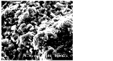
The surface of a conductive substrate (thickness 1 mm) made of a titanium flat plate was sandblasted with # 36 alumina. Palladium oxide, ruthenium chloride, and butyl titanate having a predetermined average particle size were added to the surface of the conductive substrate roughened in this manner as raw materials for the catalyst layer in an n-butanol solution (the composition of the catalyst layer is shown in Table 1). The value (mol%) shown in (1) was applied, and the mixture was dried at 120 ° C. for 10 minutes and then fired at 500 ° C. for 10 minutes. This coating-drying-baking process was repeated to prepare an anode having a catalyst layer on the surface of the conductive substrate. The average particle size of palladium oxide used as a raw material was 0.52 μm. Further, the X-ray diffraction of the catalyst layer of the anode was measured using CuKα rays, and the X-ray diffraction peak intensity and the full width at half maximum at 2θ≈34 ° were obtained. The results are shown in Table 1. The SEM image (5,000 times) of the surface of the catalyst layer of the anode obtained in Example 1 is shown in FIG.
[実施例2]
チタニウム製平板からなる導電性基体(厚み1mm)の表面を#36のアルミナでサンドブラスト処理した。このようにして粗面化された導電性基体の表面に、触媒層の原料として、所定の平均粒子径の酸化パラジウム、塩化ルテニウム、及びブチルチタネートをn-ブタノール溶液(触媒層の組成が表1に示される値(モル%)となる)を塗布し、120℃で10分間の乾燥処理を行った後、450℃で10分間の焼成処理を行った。この塗布-乾燥-焼成のプロセスを繰り返して、導電性基体の表面に触媒層が設けられた陽極を作製した。原料とした酸化パラジウムの平均粒子径は、0.17μmであった。また、陽極の触媒層について、CuKα線を用いたX線回折の測定を行い、2θ≒34°におけるX線回折ピーク強度と半値幅を求めた。結果を表1に示す。実施例2で得られた陽極の触媒層表面のSEM像(5千倍)を図2に示す。また、実施例2で得られた陽極の触媒層について、X線回折を測定して得られた2θ(°)とピーク強度(cps)との関係のグラフを図9に示す。[Example 2]
The surface of a conductive substrate (thickness 1 mm) made of a titanium flat plate was sandblasted with # 36 alumina. Palladium oxide, ruthenium chloride, and butyl titanate having a predetermined average particle size were added to the surface of the conductive substrate roughened in this manner as raw materials for the catalyst layer in an n-butanol solution (the composition of the catalyst layer is shown in Table 1). The value (mol%) shown in (1) was applied, and the mixture was dried at 120 ° C. for 10 minutes and then fired at 450 ° C. for 10 minutes. This coating-drying-baking process was repeated to prepare an anode having a catalyst layer on the surface of the conductive substrate. The average particle size of palladium oxide used as a raw material was 0.17 μm. Further, the X-ray diffraction of the catalyst layer of the anode was measured using CuKα rays, and the X-ray diffraction peak intensity and the full width at half maximum at 2θ≈34 ° were obtained. The results are shown in Table 1. The SEM image (5,000 times) of the surface of the catalyst layer of the anode obtained in Example 2 is shown in FIG. Further, with respect to the catalyst layer of the anode obtained in Example 2, a graph of the relationship between 2θ (°) obtained by measuring X-ray diffraction and the peak intensity (cps) is shown in FIG.
[実施例3]
チタニウム製平板からなる導電性基体(厚み1mm)の表面を#36のアルミナでサンドブラスト処理した。このようにして粗面化された導電性基体の表面に、触媒層の原料として、所定の平均粒子径の酸化パラジウム、塩化ルテニウム、及びブチルチタネートをn-ブタノール溶液(触媒層の組成が表1に示される値(モル%)となる)を塗布し、120℃で10分間の乾燥処理を行った後、550℃で10分間の焼成処理を行った。この塗布-乾燥-焼成のプロセスを繰り返して、導電性基体の表面に触媒層が設けられた陽極を作製した。原料とした酸化パラジウムの平均粒子径は、1.53μmであった。また、陽極の触媒層について、CuKα線を用いたX線回折の測定を行い、2θ≒34°におけるX線回折ピーク強度と半値幅を求めた。結果を表1に示す。実施例3で得られた陽極の触媒層表面のSEM像(5千倍)を図3に示す。また、実施例3で得られた陽極の触媒層について、X線回折を測定して得られた2θ(°)とピーク強度(cps)との関係のグラフを図10に示す。[Example 3]
The surface of a conductive substrate (thickness 1 mm) made of a titanium flat plate was sandblasted with # 36 alumina. Palladium oxide, ruthenium chloride, and butyl titanate having a predetermined average particle size were added to the surface of the conductive substrate roughened in this manner as raw materials for the catalyst layer in an n-butanol solution (the composition of the catalyst layer is shown in Table 1). The value (mol%) shown in (1) was applied, and the mixture was dried at 120 ° C. for 10 minutes and then fired at 550 ° C. for 10 minutes. This coating-drying-baking process was repeated to prepare an anode having a catalyst layer on the surface of the conductive substrate. The average particle size of palladium oxide used as a raw material was 1.53 μm. Further, the X-ray diffraction of the catalyst layer of the anode was measured using CuKα rays, and the X-ray diffraction peak intensity and the full width at half maximum at 2θ≈34 ° were obtained. The results are shown in Table 1. The SEM image (5,000 times) of the surface of the catalyst layer of the anode obtained in Example 3 is shown in FIG. Further, with respect to the catalyst layer of the anode obtained in Example 3, a graph of the relationship between 2θ (°) obtained by measuring X-ray diffraction and the peak intensity (cps) is shown in FIG.
[実施例4]
触媒層の原料として、表1に記載の組成となるようにして、硝酸コバルトを加えたこと以外は、実施例1と同様にして陽極を作製した。また、陽極の触媒層について、CuKα線を用いたX線回折の測定を行い、2θ≒34°におけるX線回折ピーク強度と半値幅を求めた。結果を表1に示す。実施例4で得られた陽極の触媒層表面のSEM像(1万倍)を図4に示す。また、実施例4で得られた陽極の触媒層について、X線回折を測定して得られた2θ(°)とピーク強度(cps)との関係のグラフを図11に示す。[Example 4]
An anode was prepared in the same manner as in Example 1 except that cobalt nitrate was added as a raw material for the catalyst layer so as to have the composition shown in Table 1. Further, the X-ray diffraction of the catalyst layer of the anode was measured using CuKα rays, and the X-ray diffraction peak intensity and the full width at half maximum at 2θ≈34 ° were obtained. The results are shown in Table 1. FIG. 4 shows an SEM image (10,000 times) of the surface of the catalyst layer of the anode obtained in Example 4. Further, with respect to the catalyst layer of the anode obtained in Example 4, a graph of the relationship between 2θ (°) obtained by measuring X-ray diffraction and the peak intensity (cps) is shown in FIG.
[実施例5]
チタニウム製平板からなる導電性基体(厚み1mm)の表面を#36のアルミナでサンドブラスト処理した。このようにして粗面化された導電性基体の表面に、触媒原料として、塩化パラジウム、塩化ルテニウム、ブチルチタネートを所定量含む、n-ブタノール溶液(触媒層の組成が表1に示される値(モル%)となる)を塗布し、120℃で10分間の乾燥処理を行った後、500℃で10分間の焼成処理を行った。この塗布-乾燥-焼成のプロセスを繰り返して、導電性基体の表面に触媒層が設けられた陽極を作製した。得られた陽極の触媒層表面をSEMで観察したところ、0.4~0.5μm程度の酸化パラジウムの粒子が観察され、上記の方法で任意の20個について長径を測定し、平均粒子径を算出したところ、0.15μmであった。また、陽極の触媒層について、CuKα線を用いたX線回折の測定を行い、2θ≒34°におけるX線回折ピーク強度と半値幅を求めた。結果を表1に示す。実施例5で得られた陽極の触媒層表面のSEM像(1万倍)を図5に示す。[Example 5]
The surface of a conductive substrate (thickness 1 mm) made of a titanium flat plate was sandblasted with # 36 alumina. An n-butanol solution containing a predetermined amount of palladium chloride, ruthenium chloride, and butyl titanate as catalyst raw materials on the surface of the conductive substrate roughened in this manner (the composition of the catalyst layer is shown in Table 1 (values shown in Table 1). (Mole%)) was applied and dried at 120 ° C. for 10 minutes, and then calcined at 500 ° C. for 10 minutes. This coating-drying-baking process was repeated to prepare an anode having a catalyst layer on the surface of the conductive substrate. When the surface of the catalyst layer of the obtained anode was observed by SEM, particles of palladium oxide having a size of about 0.4 to 0.5 μm were observed, and the major axis was measured for any 20 particles by the above method to obtain the average particle diameter. As a result of calculation, it was 0.15 μm. Further, the X-ray diffraction of the catalyst layer of the anode was measured using CuKα rays, and the X-ray diffraction peak intensity and the full width at half maximum at 2θ≈34 ° were obtained. The results are shown in Table 1. FIG. 5 shows an SEM image (10,000 times) of the surface of the catalyst layer of the anode obtained in Example 5.
[比較例1]
チタニウム製平板からなる導電性基体(厚み1mm)の表面を#36のアルミナでサンドブラスト処理した。このようにして粗面化された導電性基体の表面に、触媒原料として、塩化パラジウム、塩化ルテニウム、及びブチルチタネートを所定量含む、n-ブタノール溶液を塗布(触媒層の組成が表1に示される値(モル%)となる)し、120℃で10分間の乾燥処理を行った後、400℃で10分間の焼成処理を行った。この塗布-乾燥-焼成のプロセスを繰り返して、導電性基体の表面に触媒層が設けられた陽極を作製した。得られた陽極の触媒層表面をSEMで観察したところ、酸化パラジウムの粒子は観察されなかった。また、陽極の触媒層について、CuKα線を用いたX線回折の測定を行い、2θ≒34°におけるX線回折ピーク強度と半値幅を求めた。結果を表1に示す。比較例1で得られた陽極の触媒層表面のSEM像(5千倍)を図6に示す。[Comparative Example 1]
The surface of a conductive substrate (thickness 1 mm) made of a titanium flat plate was sandblasted with # 36 alumina. An n-butanol solution containing a predetermined amount of palladium chloride, ruthenium chloride, and butyl titanate as catalyst raw materials was applied to the surface of the conductive substrate roughened in this manner (the composition of the catalyst layer is shown in Table 1). After drying at 120 ° C. for 10 minutes, firing treatment was performed at 400 ° C. for 10 minutes. This coating-drying-baking process was repeated to prepare an anode having a catalyst layer on the surface of the conductive substrate. When the surface of the catalyst layer of the obtained anode was observed by SEM, no particles of palladium oxide were observed. Further, the X-ray diffraction of the catalyst layer of the anode was measured using CuKα rays, and the X-ray diffraction peak intensity and the full width at half maximum at 2θ≈34 ° were obtained. The results are shown in Table 1. FIG. 6 shows an SEM image (5,000 times) of the surface of the catalyst layer of the anode obtained in Comparative Example 1.
[比較例2]
チタニウム製平板からなる導電性基体(厚み1mm)の表面を#36のアルミナでサンドブラスト処理した。このようにして粗面化された導電性基体の表面に、触媒原料として、塩化ルテニウム及びブチルチタネートを所定量含む、n-ブタノール溶液を塗布(触媒層の組成が表1に示される値(モル%)となる)し、120℃で10分間の乾燥処理を行った後、500℃で10分間の焼成処理を行った。この塗布-乾燥-焼成のプロセスを繰り返して、導電性基体の表面に触媒層が設けられた陽極を作製した。得られた陽極の触媒層について、X線回折の測定を行ったが、触媒層がパラジウムを含んでいないため、当然ながら2θ≒34°におけるX線回折ピークは見られなかった。比較例2で得られた陽極の触媒層表面のSEM像(5千倍)を図7に示す。[Comparative Example 2]
The surface of a conductive substrate (thickness 1 mm) made of a titanium flat plate was sandblasted with # 36 alumina. An n-butanol solution containing a predetermined amount of ruthenium chloride and butyl titanate as catalyst raw materials was applied to the surface of the conductive substrate roughened in this manner (the composition of the catalyst layer is the value shown in Table 1 (mol). %), And then a drying treatment at 120 ° C. for 10 minutes and then a firing treatment at 500 ° C. for 10 minutes. This coating-drying-baking process was repeated to prepare an anode having a catalyst layer on the surface of the conductive substrate. X-ray diffraction was measured for the obtained catalyst layer of the anode, but since the catalyst layer did not contain palladium, naturally no X-ray diffraction peak was observed at 2θ≈34 °. FIG. 7 shows an SEM image (5,000 times) of the surface of the catalyst layer of the anode obtained in Comparative Example 2.
[比較例3]
原料とした酸化パラジウムの平均粒子径が、5.14μmであったこと以外は、実施例1と同様にして、陽極を作製した。また、陽極の触媒層について、CuKα線を用いたX線回折の測定を行い、2θ≒34°におけるX線回折ピーク強度と半値幅を求めた。結果を表1に示す。比較例3で得られた陽極の触媒層表面のSEM像(5千倍)を図8に示す。[Comparative Example 3]
An anode was prepared in the same manner as in Example 1 except that the average particle size of palladium oxide used as a raw material was 5.14 μm. Further, the X-ray diffraction of the catalyst layer of the anode was measured using CuKα rays, and the X-ray diffraction peak intensity and the full width at half maximum at 2θ≈34 ° were obtained. The results are shown in Table 1. FIG. 8 shows an SEM image (5,000 times) of the surface of the catalyst layer of the anode obtained in Comparative Example 3.
<0.1%塩水からの塩素発生効率の測定>
それぞれ、実施例1~5及び比較例1~3で得られた陽極と、陰極としてステンレス鋼を使用し、電流密度3A/dm2、電解温度17℃で、0.1%塩水(塩化ナトリウム水溶液)を電気分解し、有効塩素濃度から塩素発生効率(1100時間経過後)を求めた。結果を表1に示す。<Measurement of chlorine generation efficiency from 0.1% salt water>
Using the anodes obtained in Examples 1 to 5 and Comparative Examples 1 to 3, stainless steel as the cathode, 0.1% salt water (sodium chloride aqueous solution) at a current density of 3 A / dm 2 and an electrolysis temperature of 17 ° C., respectively. ) Was electrolyzed, and the chlorine generation efficiency (after 1100 hours had elapsed) was obtained from the effective chlorine concentration. The results are shown in Table 1.

*表1において、実施例5の酸化パラジウムの平均粒子径は、触媒層の表面をSEMで観察して測定した値である。 * In Table 1, the average particle size of palladium oxide in Example 5 is a value measured by observing the surface of the catalyst layer with SEM.
<塩水濃度と塩素発生効率の関係の測定>
実施例4で得られた陽極と、陰極としてステンレス鋼を使用し、各塩水濃度(0.1%、0.15%または0.5%)の塩水を電気分解し、有効塩素濃度から塩素発生効率を求めた。このとき、図12~14のグラフに示されるように、それぞれの塩水濃度において、電流密度を4.2A/dm2とした場合について、塩素発生効率(1100時間経過後)を求めた。温度と塩素発生効率との関係を示すグラフを図12~14に示す。なお、図12に示されるグラフから明らかなとおり、塩水濃度0.1%の場合、電解温度が10℃でも、塩素発生効率は50%以上であった。図13に示されるグラフから明らかなとおり、塩水濃度0.15%の場合、電解温度が5℃でも、塩素発生効率は50%以上であった。図14に示されるグラフから明らかなとおり、塩水濃度0.5%の場合、電解温度が2℃でも、塩素発生効率は70%以上であった。<Measurement of the relationship between salt water concentration and chlorine generation efficiency>
Using the anode obtained in Example 4 and stainless steel as the cathode, salt water having each salt water concentration (0.1%, 0.15% or 0.5%) was electrolyzed to generate chlorine from the effective chlorine concentration. I asked for efficiency. At this time, as shown in the graphs of FIGS. 12 to 14, the chlorine generation efficiency (after 1100 hours had elapsed) was determined when the current density was 4.2 A / dm 2 at each salt water concentration. Graphs showing the relationship between temperature and chlorine generation efficiency are shown in FIGS. 12 to 14. As is clear from the graph shown in FIG. 12, when the salt water concentration was 0.1%, the chlorine generation efficiency was 50% or more even when the electrolysis temperature was 10 ° C. As is clear from the graph shown in FIG. 13, when the salt water concentration was 0.15%, the chlorine generation efficiency was 50% or more even when the electrolysis temperature was 5 ° C. As is clear from the graph shown in FIG. 14, when the salt water concentration was 0.5%, the chlorine generation efficiency was 70% or more even when the electrolysis temperature was 2 ° C.
<電気分解時間と塩素発生効率の経時変化>
実施例4及び比較例1で得られた陽極と、陰極としてステンレス鋼を使用し、電流密度3A/dm2、電解温度2℃で、0.1%塩水(塩化ナトリウム水溶液)を電気分解し、有効塩素濃度から塩素発生効率を求めた。この電気分解を継続して行い、電気分解時間と塩素発生効率の経時変化を測定した。得られたグラフを図15に示す。図15に示されるグラフから明らかなとおり、実施例4の陽極を用いた場合、電気分解時間が4500時間を超えても、塩素発生効率があまり低下していなかった(電気分解0時間で塩素発生効率が46%、電気分解4573時間で塩素発生効率は42%であった)。一方、比較例1の陽極を用いた場合、初期の塩素発生効率は高い(電気分解0時間で塩素発生効率は46%)ものの、電気分化時間が1000時間を超えた際には、塩素発生効率がかなり低下した(1176時間で塩素発生効率は39%)。<Changes in electrolysis time and chlorine generation efficiency over time>
Using the anodes obtained in Example 4 and Comparative Example 1 and stainless steel as the cathode, 0.1% salt water (sodium chloride aqueous solution) was electrolyzed at a current density of 3 A / dm 2 and an electrolytic temperature of 2 ° C. The chlorine generation efficiency was calculated from the effective chlorine concentration. This electrolysis was continued, and the changes over time in the electrolysis time and chlorine generation efficiency were measured. The obtained graph is shown in FIG. As is clear from the graph shown in FIG. 15, when the anode of Example 4 was used, the chlorine generation efficiency did not decrease so much even if the electrolysis time exceeded 4500 hours (chlorine generation in 0 hours of electrolysis). The efficiency was 46%, and the chlorine generation efficiency was 42% after 4573 hours of electrolysis). On the other hand, when the anode of Comparative Example 1 is used, the initial chlorine generation efficiency is high (the chlorine generation efficiency is 46% in 0 hours of electrolysis), but when the electrolysis time exceeds 1000 hours, the chlorine generation efficiency is high. Was significantly reduced (chlorine generation efficiency was 39% in 1176 hours).
Claims (7)
前記触媒層は、少なくとも、酸化パラジウム、酸化ルテニウム、及び酸化チタンを含んでおり、
前記酸化パラジウムは、平均粒子径が5μm以下の粒子であり、
前記触媒層は、CuKα線を用いたX線回折法によって測定される、酸化パラジウムの回折ピーク2θ=33°~35°の範囲におけるX線回折ピーク半値幅が、1.5deg以下であり、
濃度が0.1~1%の金属塩化物水溶液の電気分解に用いられる、塩素発生用電極。 A chlorine generating electrode comprising a conductive substrate and a catalyst layer provided on the conductive substrate.
The catalyst layer contains at least palladium oxide, ruthenium oxide, and titanium oxide.
The palladium oxide is a particle having an average particle diameter of 5 μm or less, and has an average particle diameter of 5 μm or less.
The catalyst layer has an X-ray diffraction peak half-value width in the range of palladium oxide diffraction peak 2θ = 33 ° to 35 °, which is measured by an X-ray diffraction method using CuKα rays, and is 1.5 deg or less.
An electrode for generating chlorine used for electrolysis of an aqueous metal chloride solution having a concentration of 0.1 to 1%.
少なくとも、パラジウム化合物、ルテニウム化合物、及びチタン化合物を含む溶液を導電性基体上に塗布する塗布工程と、
前記溶液が塗布された前記導電性基体を焼成する焼成工程と、
を備えており、
前記パラジウム化合物として、平均粒子径が5μm以下の酸化パラジウム粒子を用いる、請求項1~3のいずれか1項に記載の塩素発生用電極の製造方法。 A method for manufacturing a chlorine generating electrode, comprising a conductive substrate and a catalyst layer provided on the conductive substrate.
At least, a coating step of applying a solution containing a palladium compound, a ruthenium compound, and a titanium compound onto a conductive substrate, and
A firing step of firing the conductive substrate coated with the solution, and
Equipped with
The method for producing a chlorine generating electrode according to any one of claims 1 to 3, wherein palladium oxide particles having an average particle diameter of 5 μm or less are used as the palladium compound.
少なくとも、パラジウム化合物、ルテニウム化合物、及びチタン化合物を含む溶液を導電性基体上に塗布する塗布工程と、
前記溶液が塗布された前記導電性基体を焼成する焼成工程と、
を備えており、
前記パラジウム化合物として、塩化パラジウム及び硝酸パラジウムの少なくとも一方を用い、
前記焼成工程において、400~600℃の温度で加熱して、前記塩化パラジウム及び硝酸パラジウムの少なくとも一方から平均粒子径が5μm以下の酸化パラジウム粒子を生成させる、請求項1~3のいずれか1項に記載の塩素発生用電極の製造方法。 A method for manufacturing a chlorine generating electrode, comprising a conductive substrate and a catalyst layer provided on the conductive substrate.
At least, a coating step of applying a solution containing a palladium compound, a ruthenium compound, and a titanium compound onto a conductive substrate, and
A firing step of firing the conductive substrate coated with the solution, and
Equipped with
At least one of palladium chloride and palladium nitrate was used as the palladium compound.
3. The method for manufacturing an electrode for chlorine generation described in 1.
A method for producing hypochlorite, comprising a step of electrolyzing an aqueous metal chloride solution using the chlorine generating electrode according to any one of claims 1 to 3.
Applications Claiming Priority (3)
| Application Number | Priority Date | Filing Date | Title |
|---|---|---|---|
| JP2015190314 | 2015-09-28 | ||
| JP2015190314 | 2015-09-28 | ||
| PCT/JP2016/078404 WO2017057337A1 (en) | 2015-09-28 | 2016-09-27 | Electrode for generating chlorine, and method for manufacturing same |
Publications (2)
| Publication Number | Publication Date |
|---|---|
| JPWO2017057337A1 JPWO2017057337A1 (en) | 2018-07-19 |
| JP7073104B2 true JP7073104B2 (en) | 2022-05-23 |
Family
ID=58423826
Family Applications (1)
| Application Number | Title | Priority Date | Filing Date |
|---|---|---|---|
| JP2017543417A Active JP7073104B2 (en) | 2015-09-28 | 2016-09-27 | Electrode for chlorine generation and its manufacturing method |
Country Status (5)
| Country | Link |
|---|---|
| EP (1) | EP3358043A4 (en) |
| JP (1) | JP7073104B2 (en) |
| KR (1) | KR20180058702A (en) |
| CN (1) | CN107949663A (en) |
| WO (1) | WO2017057337A1 (en) |
Families Citing this family (4)
| Publication number | Priority date | Publication date | Assignee | Title |
|---|---|---|---|---|
| KR20190022333A (en) * | 2017-08-23 | 2019-03-06 | 주식회사 엘지화학 | Anode for electrolysis and preparation method thereof |
| KR102355824B1 (en) * | 2018-12-27 | 2022-01-26 | 코웨이 주식회사 | Electrode catalyst layer composed of palladium, iridium, and tantalum, and sterilizing water generating module coated with the electrode catalyst |
| KR102214152B1 (en) * | 2019-04-29 | 2021-02-09 | 포항공과대학교 산학협력단 | M/Ru-Based Chlorine Evolution Reaction Catalysts With High Selectivity For Preventing Corrosion Of Balanced Water Treatment System |
| KR102648323B1 (en) * | 2021-12-13 | 2024-03-14 | 경북대학교 산학협력단 | Pt-Ru-Ti catalyst electrode for ballast water electrolysis |
Citations (2)
| Publication number | Priority date | Publication date | Assignee | Title |
|---|---|---|---|---|
| JP2007239040A (en) | 2006-03-09 | 2007-09-20 | Ishifuku Metal Ind Co Ltd | Electrode for electrolysis |
| JP2009052069A (en) | 2007-08-24 | 2009-03-12 | Ishifuku Metal Ind Co Ltd | Electrode for electrolysis |
Family Cites Families (9)
| Publication number | Priority date | Publication date | Assignee | Title |
|---|---|---|---|---|
| JPS5137877A (en) * | 1974-09-27 | 1976-03-30 | Asahi Chemical Ind | Denkaiyodenkyoku oyobi sonoseizoho |
| JPS51116182A (en) * | 1975-04-04 | 1976-10-13 | Tdk Corp | An electrode |
| JPS5518503A (en) * | 1978-07-21 | 1980-02-08 | Japan Carlit Co Ltd:The | Electrode for electrolytic manufacturing hypochlorite |
| JPS5861286A (en) * | 1981-10-08 | 1983-04-12 | Tdk Corp | Electrode for electrolysis and its production |
| DE3227718A1 (en) | 1982-07-24 | 1984-01-26 | Erno Raumfahrttechnik Gmbh, 2800 Bremen | LOW-TEMPERATURE HEATER, ESPECIALLY FOR GREENHOUSES |
| JP3319880B2 (en) | 1994-07-22 | 2002-09-03 | クロリンエンジニアズ株式会社 | Anode for producing hypochlorite and method for producing the same |
| JP3319887B2 (en) * | 1994-10-05 | 2002-09-03 | クロリンエンジニアズ株式会社 | Method for producing hypochlorite |
| US6572758B2 (en) * | 2001-02-06 | 2003-06-03 | United States Filter Corporation | Electrode coating and method of use and preparation thereof |
| AU2005325733B2 (en) | 2005-01-27 | 2010-06-10 | Industrie De Nora S.P.A. | High efficiency hypochlorite anode coating |
-
2016
- 2016-09-27 EP EP16851508.8A patent/EP3358043A4/en not_active Withdrawn
- 2016-09-27 CN CN201680050732.9A patent/CN107949663A/en active Pending
- 2016-09-27 KR KR1020187002346A patent/KR20180058702A/en not_active Application Discontinuation
- 2016-09-27 JP JP2017543417A patent/JP7073104B2/en active Active
- 2016-09-27 WO PCT/JP2016/078404 patent/WO2017057337A1/en active Application Filing
Patent Citations (2)
| Publication number | Priority date | Publication date | Assignee | Title |
|---|---|---|---|---|
| JP2007239040A (en) | 2006-03-09 | 2007-09-20 | Ishifuku Metal Ind Co Ltd | Electrode for electrolysis |
| JP2009052069A (en) | 2007-08-24 | 2009-03-12 | Ishifuku Metal Ind Co Ltd | Electrode for electrolysis |
Also Published As
| Publication number | Publication date |
|---|---|
| CN107949663A (en) | 2018-04-20 |
| JPWO2017057337A1 (en) | 2018-07-19 |
| EP3358043A1 (en) | 2018-08-08 |
| WO2017057337A1 (en) | 2017-04-06 |
| EP3358043A4 (en) | 2019-06-26 |
| KR20180058702A (en) | 2018-06-01 |
Similar Documents
| Publication | Publication Date | Title |
|---|---|---|
| JP7073104B2 (en) | Electrode for chlorine generation and its manufacturing method | |
| JP4560089B2 (en) | Electrode used for electrolysis of aqueous solution to produce hypochlorite | |
| TW200417634A (en) | Coatings for the inhibition of undesirable oxidation in an electrochemical cell | |
| US11326266B2 (en) | Electrode | |
| US7001494B2 (en) | Electrolytic cell and electrodes for use in electrochemical processes | |
| KR20190022333A (en) | Anode for electrolysis and preparation method thereof | |
| JP6920998B2 (en) | Anode for electrolysis generation of chlorine | |
| JP2009197284A (en) | Electrode and its production method | |
| JP2011202206A (en) | Insoluble electrode and method of producing the same | |
| US20070261968A1 (en) | High efficiency hypochlorite anode coating | |
| RU2379380C2 (en) | High-efficiency anode coating for producing hypochlorite | |
| WO2011102431A1 (en) | Electrode base, negative electrode for aqueous solution electrolysis using same, method for producing the electrode base, and method for producing the negative electrode for aqueous solution electrolysis | |
| RU2660362C1 (en) | Cathode for electrolysis and the method of its manufacture and electrolytic cell for electrolysis | |
| EA023083B1 (en) | Electrode for cathode hydrogen evolution in electrolytic process | |
| JP2836840B2 (en) | Electrode for chlorine generation and method for producing the same | |
| TW201725285A (en) | Electrode | |
| RU2425176C2 (en) | Method to produce electrode, electrode (versions) and electrolytic cell (versions) | |
| JP2004360067A (en) | Electrode for electrolysis, and its production method | |
| RU2818275C1 (en) | Oxygen generation electrode | |
| JP7052130B1 (en) | Electrode for chlorine generation and its manufacturing method | |
| KR102576668B1 (en) | Electrode for Electrolysis | |
| KR20190037519A (en) | Coating composition for electrolysis anode | |
| WO2022018962A1 (en) | Oxygen-generating electrode | |
| WO2022136455A1 (en) | Electrolyser for electrochlorination processes and a self-cleaning electrochlorination system | |
| JP2023035268A (en) | Electrode for chlorine generation and production method thereof |
Legal Events
| Date | Code | Title | Description |
|---|---|---|---|
| A621 | Written request for application examination |
Free format text: JAPANESE INTERMEDIATE CODE: A621 Effective date: 20190808 |
|
| A131 | Notification of reasons for refusal |
Free format text: JAPANESE INTERMEDIATE CODE: A131 Effective date: 20200616 |
|
| A521 | Request for written amendment filed |
Free format text: JAPANESE INTERMEDIATE CODE: A523 Effective date: 20200806 |
|
| A02 | Decision of refusal |
Free format text: JAPANESE INTERMEDIATE CODE: A02 Effective date: 20200908 |
|
| A521 | Request for written amendment filed |
Free format text: JAPANESE INTERMEDIATE CODE: A523 Effective date: 20201207 |
|
| C60 | Trial request (containing other claim documents, opposition documents) |
Free format text: JAPANESE INTERMEDIATE CODE: C60 Effective date: 20201207 |
|
| C11 | Written invitation by the commissioner to file amendments |
Free format text: JAPANESE INTERMEDIATE CODE: C11 Effective date: 20201222 |
|
| A911 | Transfer to examiner for re-examination before appeal (zenchi) |
Free format text: JAPANESE INTERMEDIATE CODE: A911 Effective date: 20210120 |
|
| C21 | Notice of transfer of a case for reconsideration by examiners before appeal proceedings |
Free format text: JAPANESE INTERMEDIATE CODE: C21 Effective date: 20210126 |
|
| A912 | Re-examination (zenchi) completed and case transferred to appeal board |
Free format text: JAPANESE INTERMEDIATE CODE: A912 Effective date: 20210226 |
|
| C211 | Notice of termination of reconsideration by examiners before appeal proceedings |
Free format text: JAPANESE INTERMEDIATE CODE: C211 Effective date: 20210302 |
|
| C22 | Notice of designation (change) of administrative judge |
Free format text: JAPANESE INTERMEDIATE CODE: C22 Effective date: 20210727 |
|
| C22 | Notice of designation (change) of administrative judge |
Free format text: JAPANESE INTERMEDIATE CODE: C22 Effective date: 20211005 |
|
| C13 | Notice of reasons for refusal |
Free format text: JAPANESE INTERMEDIATE CODE: C13 Effective date: 20211214 |
|
| C141 | Inquiry by the administrative judge |
Free format text: JAPANESE INTERMEDIATE CODE: C141 Effective date: 20211214 |
|
| A521 | Request for written amendment filed |
Free format text: JAPANESE INTERMEDIATE CODE: A523 Effective date: 20220203 |
|
| C54 | Written response to inquiry |
Free format text: JAPANESE INTERMEDIATE CODE: C54 Effective date: 20220203 |
|
| C23 | Notice of termination of proceedings |
Free format text: JAPANESE INTERMEDIATE CODE: C23 Effective date: 20220315 |
|
| C03 | Trial/appeal decision taken |
Free format text: JAPANESE INTERMEDIATE CODE: C03 Effective date: 20220419 |
|
| C30A | Notification sent |
Free format text: JAPANESE INTERMEDIATE CODE: C3012 Effective date: 20220419 |
|
| A61 | First payment of annual fees (during grant procedure) |
Free format text: JAPANESE INTERMEDIATE CODE: A61 Effective date: 20220511 |
|
| R150 | Certificate of patent or registration of utility model |
Ref document number: 7073104 Country of ref document: JP Free format text: JAPANESE INTERMEDIATE CODE: R150 |