JP7066724B2 - Mounting base with electrical device module and electrical device module - Google Patents
Mounting base with electrical device module and electrical device module Download PDFInfo
- Publication number
- JP7066724B2 JP7066724B2 JP2019538155A JP2019538155A JP7066724B2 JP 7066724 B2 JP7066724 B2 JP 7066724B2 JP 2019538155 A JP2019538155 A JP 2019538155A JP 2019538155 A JP2019538155 A JP 2019538155A JP 7066724 B2 JP7066724 B2 JP 7066724B2
- Authority
- JP
- Japan
- Prior art keywords
- housing
- electronic device
- device module
- spring
- module according
- Prior art date
- Legal status (The legal status is an assumption and is not a legal conclusion. Google has not performed a legal analysis and makes no representation as to the accuracy of the status listed.)
- Active
Links
- 238000013016 damping Methods 0.000 claims description 2
- 230000000694 effects Effects 0.000 claims description 2
- 239000004020 conductor Substances 0.000 description 3
- 229920001971 elastomer Polymers 0.000 description 2
- 239000000806 elastomer Substances 0.000 description 2
- 239000004033 plastic Substances 0.000 description 2
- 230000035939 shock Effects 0.000 description 2
- 238000005452 bending Methods 0.000 description 1
- 239000003990 capacitor Substances 0.000 description 1
- 230000001419 dependent effect Effects 0.000 description 1
- 238000002347 injection Methods 0.000 description 1
- 239000007924 injection Substances 0.000 description 1
- 238000009434 installation Methods 0.000 description 1
- 239000002184 metal Substances 0.000 description 1
- 238000000926 separation method Methods 0.000 description 1
- 239000007787 solid Substances 0.000 description 1
Images


Classifications
-
- H—ELECTRICITY
- H05—ELECTRIC TECHNIQUES NOT OTHERWISE PROVIDED FOR
- H05K—PRINTED CIRCUITS; CASINGS OR CONSTRUCTIONAL DETAILS OF ELECTRIC APPARATUS; MANUFACTURE OF ASSEMBLAGES OF ELECTRICAL COMPONENTS
- H05K7/00—Constructional details common to different types of electric apparatus
- H05K7/14—Mounting supporting structure in casing or on frame or rack
- H05K7/1462—Mounting supporting structure in casing or on frame or rack for programmable logic controllers [PLC] for automation or industrial process control
- H05K7/1474—Mounting of modules, e.g. on a base or rail or wall
-
- H—ELECTRICITY
- H05—ELECTRIC TECHNIQUES NOT OTHERWISE PROVIDED FOR
- H05K—PRINTED CIRCUITS; CASINGS OR CONSTRUCTIONAL DETAILS OF ELECTRIC APPARATUS; MANUFACTURE OF ASSEMBLAGES OF ELECTRICAL COMPONENTS
- H05K5/00—Casings, cabinets or drawers for electric apparatus
- H05K5/02—Details
- H05K5/0217—Mechanical details of casings
- H05K5/0234—Feet; Stands; Pedestals, e.g. wheels for moving casing on floor
-
- H—ELECTRICITY
- H05—ELECTRIC TECHNIQUES NOT OTHERWISE PROVIDED FOR
- H05K—PRINTED CIRCUITS; CASINGS OR CONSTRUCTIONAL DETAILS OF ELECTRIC APPARATUS; MANUFACTURE OF ASSEMBLAGES OF ELECTRICAL COMPONENTS
- H05K5/00—Casings, cabinets or drawers for electric apparatus
- H05K5/02—Details
- H05K5/0204—Mounting supporting structures on the outside of casings
-
- H—ELECTRICITY
- H01—ELECTRIC ELEMENTS
- H01R—ELECTRICALLY-CONDUCTIVE CONNECTIONS; STRUCTURAL ASSOCIATIONS OF A PLURALITY OF MUTUALLY-INSULATED ELECTRICAL CONNECTING ELEMENTS; COUPLING DEVICES; CURRENT COLLECTORS
- H01R9/00—Structural associations of a plurality of mutually-insulated electrical connecting elements, e.g. terminal strips or terminal blocks; Terminals or binding posts mounted upon a base or in a case; Bases therefor
- H01R9/22—Bases, e.g. strip, block, panel
- H01R9/24—Terminal blocks
- H01R9/26—Clip-on terminal blocks for side-by-side rail- or strip-mounting
-
- H—ELECTRICITY
- H02—GENERATION; CONVERSION OR DISTRIBUTION OF ELECTRIC POWER
- H02B—BOARDS, SUBSTATIONS OR SWITCHING ARRANGEMENTS FOR THE SUPPLY OR DISTRIBUTION OF ELECTRIC POWER
- H02B1/00—Frameworks, boards, panels, desks, casings; Details of substations or switching arrangements
- H02B1/015—Boards, panels, desks; Parts thereof or accessories therefor
- H02B1/04—Mounting thereon of switches or of other devices in general, the switch or device having, or being without, casing
- H02B1/052—Mounting on rails
- H02B1/0526—Mounting on rails locking or releasing devices actuated from the front face of the apparatus
-
- H—ELECTRICITY
- H05—ELECTRIC TECHNIQUES NOT OTHERWISE PROVIDED FOR
- H05K—PRINTED CIRCUITS; CASINGS OR CONSTRUCTIONAL DETAILS OF ELECTRIC APPARATUS; MANUFACTURE OF ASSEMBLAGES OF ELECTRICAL COMPONENTS
- H05K5/00—Casings, cabinets or drawers for electric apparatus
- H05K5/02—Details
- H05K5/0217—Mechanical details of casings
- H05K5/0221—Locks; Latches
Landscapes
- Engineering & Computer Science (AREA)
- Microelectronics & Electronic Packaging (AREA)
- Automation & Control Theory (AREA)
- Mounting Components In General For Electric Apparatus (AREA)
Description
本発明は、請求項1の前文に記載の電子機器モジュール、及び支持レールを有する取付けベースと電子機器モジュールとからなる装置に関する。
The present invention relates to the electronic device module according to the preamble of
クラス固有タイプの電子機器モジュールは、例えば、工作機械の制御盤や同様の機器など、激しい振動や衝撃にさらされる場所で使用されることがよくある。 Class-specific electronic device modules are often used in places exposed to intense vibrations and shocks, such as machine tool control panels and similar equipment.
本発明の根底にある目的は、そのような振動によって引き起こされる損傷の危険性が減少するように電子機器モジュールを構成することである。 An underlying object of the present invention is to construct an electronic device module so that the risk of damage caused by such vibrations is reduced.
本発明は請求項1の主題事項によってこの目的を解決する。本発明の有利な実施形態は、従属請求項に見出される。
The present invention solves this object by the subject matter of
請求項1は、取付け足部を有するハウジングを備え、ハウジングは支持レール上に取り付けられ、取付けベース上に取り付けられる支持レールに電子機器モジュールを締結するのに適している電子機器モジュールを生成する。
少なくとも1つのばね要素-好ましいが絶対的に必要ではない付随的な構成に従って、ハウジングの取付け足部から距離を置いて配置される-がハウジングの下部領域に配備され、該下部領域はハウジングの取付け時に取付けベースに対向し、少なくとも1つのばね要素は、ハウジングが取付けベースに対して振動したときに減衰効果を有するように釣り合いが取れて構成されている。従って、衝撃又は振動によって引き起こされる損害の危険性は効果的に減少する。ここで、2つ以上のばね要素がハウジング上に構成されると有利である。
The first aspect comprises a housing having a mounting foot, the housing being mounted on a support rail to generate an electronic device module suitable for fastening the device module to a support rail mounted on a mounting base.
At least one spring element-located away from the mounting foot of the housing according to ancillary configurations that are preferred but not absolutely necessary-is deployed in the lower area of the housing, which lower area is the mounting of the housing. Sometimes facing the mounting base, at least one spring element is configured to be balanced so that it has a damping effect when the housing vibrates against the mounting base. Therefore, the risk of damage caused by impact or vibration is effectively reduced. Here, it is advantageous that two or more spring elements are configured on the housing.
それらの構成において、少なくとも1つ又は複数の又は全てのばね要素がハウジングの壁、特に側壁の一部として一体化されることにより、簡素に且つ費用対効果が高く実現される。或いは、ばね要素は、例えばエラストマーばねの形態で、ハウジングに取り付けられるか又は射出成形され得る。 In those configurations, at least one or more or all of the spring elements are integrated as part of the housing wall, especially the sidewalls, which is simply and cost-effectively realized. Alternatively, the spring element may be attached to the housing or injection molded, for example in the form of an elastomer spring.
更に、ハウジングの取付け状態で取付けベースに対向するハウジングの側部に形成されたハウジングの下部、外側領域に、ハウジングが1つ又は複数のばね要素を含めば、有利で安全である。 Further, it is advantageous and safe if the housing includes one or more spring elements in the lower, outer region of the housing formed on the side of the housing facing the mounting base in the mounted state of the housing.
更に、ハウジングの複数の側壁が夫々1つ又は複数のばね要素を含み、複数の箇所の夫々に亘って分散された弾性支持を達成れば、有利である。 Further, it is advantageous if the plurality of sidewalls of the housing each include one or more spring elements to achieve distributed elastic support across each of the plurality of locations.
ここで、少なくとも1つのばね要素が少なくとも1つのばねバー又は夫々2つ以上のばねバーを含み、それらが取付けベースに面する側でハウジングから下方に突き出ていれば、費用対効果が高く、更にコンパクトな構成の点でまた有利である。 Here, it is cost-effective and further if at least one spring element comprises at least one spring bar or two or more spring bars each protruding downward from the housing on the side facing the mounting base. It is also advantageous in terms of compact configuration.
ここで、様々なバージョンのばねバーを実現することができ、そのうちの幾つかは、図面を参照して以下により詳細に説明される。 Here, various versions of spring bars can be realized, some of which are described in more detail below with reference to the drawings.
本発明は更に、支持レールと、関連する請求項の1つ以上に従って、一列に互いに隣接して配置された支持レール上に配置された電子機器モジュールとを有する取付けベースの構成を生成する。 The invention further produces a mounting base configuration with support rails and electronic device modules arranged on support rails arranged adjacent to each other in a row according to one or more of the relevant claims.
以下において、本発明は図面を参照して代表的な実施形態を基により詳細に記載される。
以下において、図6に従った公知の電子機器モジュールの基本構成がまず説明される。「頂部」及び「底部」、「右」及び「左」などの位置情報及び用語は、図6の水平方向における下側取付けベースMに関連し、又は図3bに示される本発明にも関連し、このように互いに関連すると理解されるべきである。使用時には、取付けベースMもまた垂直に又は斜めに向けられてもよい。 In the following, the basic configuration of a known electronic device module according to FIG. 6 will be described first. Positional information and terms such as "top" and "bottom", "right" and "left" relate to the horizontal lower mounting base M in FIG. 6 or also to the invention shown in FIG. 3b. , It should be understood that they are related to each other in this way. In use, the mounting base M may also be oriented vertically or diagonally.
公知の電子機器モジュール1は、複数の部品から作られるハウジング2を含む。ハウジング2は非導電性のプラスチックから成るのが好ましい。ハウジングの内側には1以上の電子部品を有する機能的電子回路が配置されている。本出願の意味において、これらの電子部品は、一方では抵抗器、コンデンサ、コイル、ダイオードなどの1以上の部品を含み、また、バスバー、導電体、導電体コネクタなどの1以上の純粋に導電性の部品を含む。従って、機能的電子回路は、1以上のコネクタ3a、3b、3c…及び1以上のバスバーに限定され得るが、上記に列挙したものなど、1以上の追加の電子部品も含むことができる。好ましくは、プラグ又は導電体端部のようなプラグイン要素のための1以上のコネクタ3a、3b、…がハウジング2、この場合は上側に設けられている。
The known
少なくとも1つの支持レールTが取付けベースM上に配置され又は構成される。この場合、この支持レールTはハット形の輪郭を有する。 At least one support rail T is arranged or configured on the mounting base M. In this case, the support rail T has a hat-shaped contour.
ハウジング2は、その下部領域に取付け足部4を備え、該取付け足部は支持レールTを向いている。このハウジング2は支持レールTに取り付けられており、取付け足部4によって取り付けられている。取付け足部4は、ここには示されていない機構を介してハンドル5によってロック解除及びロックすることができる。
The
以下において、デカルト座標系X、Y、Zが、空間方向を説明するために使用される。ここで、支持レールTは、X方向に延びている(図1参照)。取付けベースMはX/Y平面内に配置されている。取付け面に直交する垂直方向をZで示す。 In the following, the Cartesian coordinate system X, Y, Z will be used to explain the spatial direction. Here, the support rail T extends in the X direction (see FIG. 1). The mounting base M is arranged in the X / Y plane. The vertical direction orthogonal to the mounting surface is indicated by Z.
ハウジング2は、+Y方向及び/又は-Y方向において支持レールTの夫々の縁部T1及びT2を越えて横方向に延びる。支持レールTの縁部T1、T2を越えてY方向及び/又は-Y方向に50-150mm延びている。ここで検討される実施形態では、ハウジング2の底側U、即ち取付けベースMに面する側Uは、取付けベースMに非常に接近する。これは、ハウジング2のその取り付け状態における水平な取付けベースMまでの距離A(図6b)が支持レールTの下方10mm未満、特に4mm未満であることを意味する。Y方向の側方の延長部分が比較的大きければ、取付けベースM及び支持レールTが振動しているときにハウジング2が動かされて、ハウジング2の底側、特にコーナー部E1及びE2の領域が取付けベースMに衝突する危険性がある。これは、言い換えると(in turn)、電子機器モジュール1の機能的電子機器及び/又は他の機能的要素を損傷するという重大な危険につながる可能性がある。
The
ハウジング2は接続要素を含み、一列に取り付けられるように構成されているのが好ましい。これは、幾つかの電子機器モジュール1を支持レールの延び方向Xに一列に取り付けることができることを意味する(より詳細には、本発明に関する図1を参照)。この目的から、電子機器モジュール1は、比較的狭い円板形状の構成を有することが好ましい。全ての電子機器モジュールが同様に構成される。しかしながら、異なるタイプI及びIIの電子機器モジュール1を提供することも可能である。これらは様々な幅(特にX方向)であり得、特に支持レールから離れて面するそれらの上部領域において異なる構成であり得る。従って、図1は、フィールドバスカプラとして設計されている第1のタイプIの電子機器モジュール1を示している。本明細書では例示的にI/Oモジュールとして構成されているが異なる機能を有することもできる第2のタイプIIの電子モジュールが、第1のタイプIの電子機器モジュール1に隣接して取り付けられている。
The
本発明に従って、上記の構成が維持され得て、維持されるのが好ましい。しかし、本発明に従って且つ図6aと図6bとは対照的に、本発明に従って、少なくとも1つのばね要素6が、各電子機器モジュール1のハウジングの下部領域に構成又は配置されている。好ましくは、ばね要素6はハウジング2に一体化されており、一体になるように構成されている。この構成はシンプルで、費用対効果が高く、機能的に安全である。他の仕様に従って、少なくとも1つのばね要素はまた、ハウジングの底部側に取り付けられたエラストマー又は金属製もしくはプラスチック製のばねの種類の別個のばね要素(例えば、板ばねの一種)であってもよい(図示せず)。
According to the present invention, the above configuration can be maintained and is preferably maintained. However, according to the present invention and in contrast to FIGS. 6a and 6b, at least one
低コストと必要な設置スペースが小さいため、ばね要素6がハウジング2と一体になるように、即ち一体化されるように構成されている仕様が好ましい。
Due to the low cost and the small installation space required, it is preferable that the
以下の記載において、各ばね要素6は個々に記載されている。本発明による電子機器モジュールには、少なくとも1つ、好ましくは2つ以上(好ましくは4つ)、さらにはそれ以上のこれらのばね要素6が取り付けられている。特に好ましいのは、4つのばね要素6a、6bを備えた構成であり、2つの各ばね要素6a、6c又は各ばね要素6b、6dが、ハウジング2の底側U上の2つの下部コーナー領域E1及びE2の領域に構成され、又はこれらのコーナー領域(支持レールTの両側上、この場合、電子機器モジュールの各側)に近いことである。タイプIIの電子モジュールは8個のばね要素さえも有する。タイプIIの電子機器モジュールは、ここでは4つのばね要素6を有するのが好ましい。
In the following description, each
図1に従って、コーナー領域は、取付けベースMに最も衝突する可能性が高い領域である。しかし、これはこの場合に固有ではなく、ここで示された進歩性のあるハウジングの好ましい構成から生じるものであり、ハウジング2の底側は、ばね要素6を除き、支持レールTの片側と大凡同じ高さである。ハウジング2の底部が階段状の構成である場合に、少なくとも1つのばね要素6を異なる位置(ここには示されていない)に配置することも理解されるだろう。
According to FIG. 1, the corner region is the region most likely to collide with the mounting base M. However, this is not unique in this case and results from the preferred configuration of the inventive step housing shown herein, the bottom side of the
図1乃至図5(及び図6)に添付した各ハウジング2は、図1に示す側面図にて大凡矩形の構成を有する。これは有利であるが必須ではない。各ハウジング2は底側Uを有し、取付け状態で取付けベースMを向いている。この取付けベースMは、例えば制御キャビネットの壁である。以下の説明において、この取付けベースMは水平と考えられる。
Each
ハウジング2の底側Uの各コーナー領域E1及びE2に構成された好ましいばね要素6、6a、6bは、各ばね要素6の領域にてばねバー7の少なくとも1つを有するハウジング2によってこれらの箇所に形成されている。このばねバー7は、この領域においてハウジング2の底側Uの隣接する下縁を越えて突起のように下方に(取付けベースMの方向に)延びる。ばねバー7を有するばね要素6は、ハウジング2の一方又は両方に、あるいはさらに多くの主側壁8及び9に構成され、及び費用対効果が高く、簡素で一体化された構成で主側壁8及び9に一体化されている。
これは特に図1b、図2c及び図3cに示される。主側壁8及び9は、特に、隣のハウジングに取り付けられ且つY/Z平面内に配置されているハウジング2の壁である。ばねバー7はこれらの側壁内に一体化されているのが好ましい。主側壁8及び9(夫々ここでは図示せず)を接続するハウジング2の下部壁又は短い側壁にばねバーを構成することも考えられる。
This is particularly shown in FIGS. 1b, 2c and 3c. The
電子機器モジュールが、1つ以上のばね要素6を備えた2つよりも多い側壁を有することも考えられる。これは、例えば、電子機器モジュールが非常に大きな構造幅を有する場合、例えば、ここでは第2の構成のタイプの電子モジュールの幅によって定義される、X方向に複数のグリッド幅を有する場合など-参照番号IIで示す。従って、第1の構成-参照番号I-の電子機器モジュールは例として4つの側壁を有し、これはX方向に内向きにさらに位置する2つの外側壁と2つの分離壁であり、しかしこの出願の意味において全ての側壁は主側壁と言及され、全ては1以上のばねバー7を有するばね要素6を備えている。これは特に図1cに示される。
It is also conceivable that the electrical device module has more than two side walls with one or
1以上のばね要素6が、一方又は両方の壁、特に主側壁8及び9に構成されることが可能である。好ましくは、2つの主側壁8及び9の夫々に、2つの夫々のばねバー7が、即ち下部の外側コーナーE1及びE2の近くに設けられる。
One or
ここで、ばねバー7はまた、バー(ここでは示さない)によってX方向に互いに接続され得る。3つのみのばね要素6が設けられ、2つがコーナーE1に配置され、1つがコーナーE2に配置されるようにすることも考えられる(ここでは図示せず)。更に、本発明による実施形態について考えられる構成であり、あまり好ましくはないが、1つ又は2つのみのばね要素6を設け、1つはコーナーE1の1つに配置され、もう1つはコーナーE1とは反対側の夫々のコーナーE2に配置される(ここでは図示せず)。そのような構成は、振動に対する改良された安全装置を既に作り出すであろうが、それは追加のばね要素6によってさらに改良することができる。最終的にまた、ばね要素6のうちの1つが取付け足部4又は底壁に一体化されている(又は別の方法でハウジング上に構成されている(夫々ここでは図示せず))ことも考えられる。
Here, the spring bars 7 can also be connected to each other in the X direction by bars (not shown here). It is also conceivable that only three
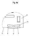
少なくとも1つのばねバー7は、一端又は両端において、ハウジング2、特に夫々の側壁8又は9に一体的に取り付けられているか、又はその上に構成されている(図4a及び図5参照)。ばねバー7の上には、ハウジング2の関連する側壁9に窓状の開口部(これも切欠き部であり得る)がある。この開口部はスロット10、特に湾曲したスロットとして形成され得る。この場合、ばねバー7もまた湾曲形状を有し、その中央領域はハウジング2の隣接する下縁から最も遠く離れたところまで延びている、即ち、その中央領域は取付けベースMに最も近い距離にあることが有利である(図1乃至図4、図5a及び図5b、図5a及び図5d参照)。
At least one
開口部が、僅か約1mmから3mmの幅(Z方向に)の狭いスロット10に形成されるのが好ましが、必須ではない。振動によってハウジング2が夫々のばねバー7の領域で取付けベースMと接触すると、前記ばねバーは開口部内、特にスロット内に撓むことがある。それによって、ばねバー7はショックを減衰する。従って、電子機器ハウジングの全体、特にその機能的電子機器は、衝撃による損傷から効果的に保護される。
It is preferred, but not required, for the openings to be formed in
次に、ばねバー7自体が、ばねバー7の上縁から開口部内、特にスロット10内に僅かに突出する突起11を含むことができる。これにより、ばね特性に影響し調整することが容易になる。ばねバー7はまた、その最下点において取付けベースから離れていてもよく、衝撃の場合には取付けベースに対して止まることができるか、又は衝撃の存在なしにアイドリング位置であっても取付けベースに対して支持され得る(図4b)。
Next, the
図5は、種々の構成のばね要素6を示す。各場合において、夫々のばね要素6のうちの1つを有するハウジング2の側壁8又は9を有する下部コーナー部分のみを示す。
FIG. 5 shows
各ばね要素6は1つのばねバー7(図5a及び図5b、図5e、図5f、図5i、図5j、図5k、図5l、図5m、図5n)又は2つのばねバー(図5c、図5d、図5g、図5h)又は2つを超えるばねバー(図示せず)を含む。
Each
ばね要素内で、各ばねバー7、7a、7bはその一端部のみ(図5c及び図5d、図5e、図5f、図5g、図5h、図5k、図5l、図5m、図5n)、又は両端部(図5a、図5b、図5i及び図5j)が側壁8に取り付けられる。
Within the spring element, each
開口部10はまた、様々な方法で構成することができる。開口部10は、湾曲した形状(図5a及び図5b、図5c及び図5d)又は三角形(図5i及び図5j)のような1つ以上のばねバー7a及び7bの撓みを許容する他の形状を有することができる。
The
ばねバー7a、7b、…がそれらの1つの端部で関連する側壁8又は9にのみ取り付けられる場合、開口部内に延在し、ばねの移動を制限し、ばね特性に影響を及ぼす、突起11としての一種のハンマーヘッド12を端部に有することが有利である(図5c及び図5d、図5e、図5f、図5g、図5h、図5k、図5l)。ハンマーヘッドは中実設計のものであってもよく、又は弧状(図5k及び図5l)又はフックとして設計されていてもよい。
If the spring bars 7a, 7b, ... Are attached only to the associated sidewalls 8 or 9 at one end of them, the
ばねバー7a、7b、…はまたハンマーヘッドを除いて、ストレートバー(図5e及び図5f、図5k及び図5l)として構成することができ、又は角度付きバーとして設計することができる(図5i及び図5j、図5m、図5n)。 The spring bars 7a, 7b, ... Can also be configured as straight bars (FIGS. 5e and 5f, FIGS. 5k and 5l) or can be designed as angled bars, with the exception of the hammer head (FIG. 5i). And FIG. 5j, FIG. 5m, FIG. 5n).
電子機器モジュール 1
ハウジング 2
コネクタ 3a、3b、3c…
取付け足部 4
ハンドル 5
ばね要素 6、6a、6b…
ばねバー 7、7a、7b…
主側壁 8、9
スロット 10
突起 11
ハンマーヘッド 12
取付けベース M
座標系 X、Y、Z
支持レールの縁部 T1、T2
ハウジングの底側 U
コーナー E1及びE2
Mounting
Handle 5
Spring bars 7, 7a, 7b ...
Mounting base M
Coordinate system X, Y, Z
Support rail edges T1, T2
Bottom side of housing U
Corners E1 and E2
Claims (16)
少なくとも1つのばね要素(6)がハウジング(2)の下部領域に配備され、該下部領域はハウジング(2)の取付け時に取付けベースに対向し、
少なくとも1つのばね要素は、ハウジング(2)が取付けベース(M)に対して振動したときに減衰効果を有するように釣り合いが取れて構成され、
少なくとも1つ又は複数の又は全てのばね要素(6)が、ハウジング(2)の側壁(8、9)と一体化されている、電子機器モジュール。 A housing (2) having a mounting foot (4) is provided, the housing (2) is mounted on a support rail (T), and an electronic device module is fastened to a support rail (T) mounted on a mounting base (M). In an electronic device module suitable for
At least one spring element (6) is deployed in the lower region of the housing (2), the lower region facing the mounting base when the housing (2) is mounted.
The at least one spring element is configured to be balanced so that it has a damping effect when the housing (2) vibrates against the mounting base (M).
An electronic device module in which at least one or more or all spring elements (6) are integrated with the sidewalls (8, 9) of the housing (2) .
Applications Claiming Priority (3)
| Application Number | Priority Date | Filing Date | Title |
|---|---|---|---|
| DE202017100172.5 | 2017-01-13 | ||
| DE202017100172.5U DE202017100172U1 (en) | 2017-01-13 | 2017-01-13 | Electronic module and mounting base with an electronic module |
| PCT/EP2018/050520 WO2018130547A1 (en) | 2017-01-13 | 2018-01-10 | Electronics module, and a mounting base comprising an electronics module |
Publications (3)
| Publication Number | Publication Date |
|---|---|
| JP2020506538A JP2020506538A (en) | 2020-02-27 |
| JP2020506538A5 JP2020506538A5 (en) | 2020-11-26 |
| JP7066724B2 true JP7066724B2 (en) | 2022-05-13 |
Family
ID=60957310
Family Applications (1)
| Application Number | Title | Priority Date | Filing Date |
|---|---|---|---|
| JP2019538155A Active JP7066724B2 (en) | 2017-01-13 | 2018-01-10 | Mounting base with electrical device module and electrical device module |
Country Status (6)
| Country | Link |
|---|---|
| US (1) | US10827634B2 (en) |
| EP (1) | EP3569042B1 (en) |
| JP (1) | JP7066724B2 (en) |
| CN (1) | CN110192438B (en) |
| DE (1) | DE202017100172U1 (en) |
| WO (1) | WO2018130547A1 (en) |
Families Citing this family (5)
| Publication number | Priority date | Publication date | Assignee | Title |
|---|---|---|---|---|
| JP1623420S (en) * | 2018-03-14 | 2019-02-04 | ||
| JP1623945S (en) * | 2018-03-14 | 2019-02-04 | ||
| DE202019100078U1 (en) * | 2019-01-09 | 2020-04-15 | Weidmüller Interface GmbH & Co. KG | Control and modular control system of an industrial automation system |
| USD1044794S1 (en) * | 2022-08-04 | 2024-10-01 | Weidmuller Interface Gmbh & Co. Kg | Computer housing |
| CN118548780B (en) * | 2024-07-30 | 2024-10-01 | 中建五局(四川)建设发展有限公司 | Thickness measuring device for gypsum self-leveling indoor terrace |
Citations (2)
| Publication number | Priority date | Publication date | Assignee | Title |
|---|---|---|---|---|
| JP2007194318A (en) | 2006-01-18 | 2007-08-02 | Omron Corp | Mounting structure of din rail-mounting electrical equipment |
| JP2014107366A (en) | 2012-11-27 | 2014-06-09 | Mitsubishi Electric Corp | Auxiliary tool and installation method of apparatus mount |
Family Cites Families (21)
| Publication number | Priority date | Publication date | Assignee | Title |
|---|---|---|---|---|
| GB1050416A (en) * | 1963-05-25 | |||
| US3160280A (en) * | 1963-08-12 | 1964-12-08 | Gen Electric | Device for mounting apparatus |
| DE2719194C3 (en) * | 1977-04-29 | 1985-01-31 | SWF Auto-Electric GmbH, 7120 Bietigheim-Bissingen | Electrical switch for attachment in a receiving part |
| CH665059A5 (en) * | 1985-04-03 | 1988-04-15 | Rdi Limited Partnership | ASSEMBLY INCLUDING A MODULAR ELECTRICAL OR ELECTRONIC CIRCUIT AND A CONNECTOR FOR CONNECTING THE CIRCUIT TO A SELF - CONTAINED ELECTRICAL SYSTEM. |
| DE4034204C2 (en) * | 1990-10-27 | 2002-04-18 | Wago Verwaltungs Gmbh | Electrical terminal with busbar connection |
| US5135415A (en) * | 1991-08-12 | 1992-08-04 | Nick Huber | Device for attaching electrical components to track |
| DE4420134C1 (en) * | 1994-06-09 | 1995-10-05 | Fichtel & Sachs Ag | Oscillation damper with mechanical traction stop |
| DE9411323U1 (en) * | 1994-07-13 | 1995-11-09 | Moeller GmbH, 53115 Bonn | Electronics housing for attachment to a mounting rail or mounting plate |
| US5775955A (en) * | 1996-09-17 | 1998-07-07 | Graube; Maris | Modular fieldbus terminal block |
| JPH11233970A (en) * | 1998-02-12 | 1999-08-27 | Omron Corp | Rail-mounted equipment |
| DE10249981B3 (en) * | 2002-10-26 | 2004-04-01 | Moeller Gmbh | Electronic control device comprises interference signal diversion plate between control module circuit board and carrier rail or carrier plate |
| DE10301003B3 (en) | 2003-01-13 | 2004-09-30 | Siemens Ag | Modular installation device |
| US7073971B2 (en) * | 2004-02-10 | 2006-07-11 | Egs Electrical Group, Llc | Apparatus and methods for detachably mounting devices to rails |
| US20060249507A1 (en) * | 2005-04-11 | 2006-11-09 | Watlow Electric Manufacturing Company | Modular controller user interface and method |
| DE202006006615U1 (en) * | 2006-04-22 | 2006-09-07 | Phoenix Contact Gmbh & Co. Kg | Electronic housing has several attachment devices in side walls, especially several openings formed so that other circuit boards can be optionally latched into attachment devices in at least two orthogonal spatial directions |
| DE102006057766B4 (en) * | 2006-12-07 | 2010-02-04 | Siemens Ag | Fastening device of electronic modules on mounting rail |
| CN101315574A (en) * | 2007-06-01 | 2008-12-03 | 鸿富锦精密工业(深圳)有限公司 | Data storage fixing device |
| TW200931732A (en) * | 2008-01-04 | 2009-07-16 | Switchlab Inc | Improvement of rail-type grounding terminal structure |
| CN203722964U (en) * | 2014-01-08 | 2014-07-16 | 矢崎(中国)投资有限公司 | Shockproof fixing structure and electrical box base provided with same |
| DE102015117427A1 (en) * | 2015-10-13 | 2017-04-13 | Phoenix Contact Gmbh & Co. Kg | locking device |
| CN105472932A (en) * | 2015-12-05 | 2016-04-06 | 重庆诚硕科技有限公司 | Shockproof device for electronic element bearing plate |
-
2017
- 2017-01-13 DE DE202017100172.5U patent/DE202017100172U1/en active Active
-
2018
- 2018-01-10 EP EP18700324.9A patent/EP3569042B1/en active Active
- 2018-01-10 US US16/473,523 patent/US10827634B2/en active Active
- 2018-01-10 JP JP2019538155A patent/JP7066724B2/en active Active
- 2018-01-10 CN CN201880006788.3A patent/CN110192438B/en active Active
- 2018-01-10 WO PCT/EP2018/050520 patent/WO2018130547A1/en unknown
Patent Citations (2)
| Publication number | Priority date | Publication date | Assignee | Title |
|---|---|---|---|---|
| JP2007194318A (en) | 2006-01-18 | 2007-08-02 | Omron Corp | Mounting structure of din rail-mounting electrical equipment |
| JP2014107366A (en) | 2012-11-27 | 2014-06-09 | Mitsubishi Electric Corp | Auxiliary tool and installation method of apparatus mount |
Also Published As
| Publication number | Publication date |
|---|---|
| US10827634B2 (en) | 2020-11-03 |
| EP3569042B1 (en) | 2023-05-03 |
| EP3569042A1 (en) | 2019-11-20 |
| US20190335597A1 (en) | 2019-10-31 |
| WO2018130547A1 (en) | 2018-07-19 |
| DE202017100172U1 (en) | 2018-04-16 |
| JP2020506538A (en) | 2020-02-27 |
| CN110192438A (en) | 2019-08-30 |
| CN110192438B (en) | 2021-12-21 |
Similar Documents
| Publication | Publication Date | Title |
|---|---|---|
| JP7066724B2 (en) | Mounting base with electrical device module and electrical device module | |
| JP4464878B2 (en) | Electrical junction box | |
| JP6062530B2 (en) | Electronic component assembly structure and electrical junction box | |
| JP6663565B2 (en) | Board connector | |
| JP5875115B2 (en) | Electrical junction box | |
| US3704394A (en) | Receptacle for printed circuit structures with bus bar mounting means | |
| CN108604746B (en) | Substrate connector | |
| JP6626066B2 (en) | Electrical junction box | |
| US9805892B2 (en) | Electronic component and electronic component assembly structure | |
| KR20080000640A (en) | Clamping device for a connection terminal | |
| JP4688489B2 (en) | Electrical connector | |
| JP5134458B2 (en) | Relay mounting structure | |
| US8123186B2 (en) | Ruggedized mounting assembly and method for stabilizing one or more computer racks | |
| KR20110009654A (en) | Circuit case with terminal | |
| US6570775B2 (en) | Circuit board assembly having a compact structure | |
| KR101483768B1 (en) | Box for vehicle | |
| KR102316364B1 (en) | Holder for surface mounted device | |
| JP4936452B2 (en) | Distribution board | |
| KR20160070019A (en) | Contact device | |
| JP6865597B2 (en) | Electronic control device | |
| JP4831763B2 (en) | Mounting structure for live cover | |
| JP2663630B2 (en) | Printed wiring board accommodation structure | |
| EP1729201A1 (en) | Shielding means | |
| JP2024015619A (en) | Impact prevention structure for electronic equipment | |
| CN110213928B (en) | Electronic device |
Legal Events
| Date | Code | Title | Description |
|---|---|---|---|
| A521 | Request for written amendment filed |
Free format text: JAPANESE INTERMEDIATE CODE: A523 Effective date: 20201016 |
|
| A621 | Written request for application examination |
Free format text: JAPANESE INTERMEDIATE CODE: A621 Effective date: 20201016 |
|
| A977 | Report on retrieval |
Free format text: JAPANESE INTERMEDIATE CODE: A971007 Effective date: 20211111 |
|
| A131 | Notification of reasons for refusal |
Free format text: JAPANESE INTERMEDIATE CODE: A131 Effective date: 20211116 |
|
| A521 | Request for written amendment filed |
Free format text: JAPANESE INTERMEDIATE CODE: A523 Effective date: 20211223 |
|
| TRDD | Decision of grant or rejection written | ||
| A01 | Written decision to grant a patent or to grant a registration (utility model) |
Free format text: JAPANESE INTERMEDIATE CODE: A01 Effective date: 20220419 |
|
| A61 | First payment of annual fees (during grant procedure) |
Free format text: JAPANESE INTERMEDIATE CODE: A61 Effective date: 20220427 |
|
| R150 | Certificate of patent or registration of utility model |
Ref document number: 7066724 Country of ref document: JP Free format text: JAPANESE INTERMEDIATE CODE: R150 |