JP7050002B2 - Visible laser welding of electronic packaging, automotive electrical equipment, batteries, and other components - Google Patents
Visible laser welding of electronic packaging, automotive electrical equipment, batteries, and other components Download PDFInfo
- Publication number
- JP7050002B2 JP7050002B2 JP2018556818A JP2018556818A JP7050002B2 JP 7050002 B2 JP7050002 B2 JP 7050002B2 JP 2018556818 A JP2018556818 A JP 2018556818A JP 2018556818 A JP2018556818 A JP 2018556818A JP 7050002 B2 JP7050002 B2 JP 7050002B2
- Authority
- JP
- Japan
- Prior art keywords
- laser beam
- metal piece
- component
- metal
- welding
- Prior art date
- Legal status (The legal status is an assumption and is not a legal conclusion. Google has not performed a legal analysis and makes no representation as to the accuracy of the status listed.)
- Active
Links
- 238000003466 welding Methods 0.000 title claims description 97
- 238000004100 electronic packaging Methods 0.000 title 1
- 229910052751 metal Inorganic materials 0.000 claims description 118
- 239000002184 metal Substances 0.000 claims description 118
- 238000000034 method Methods 0.000 claims description 102
- 239000000463 material Substances 0.000 claims description 90
- 239000010949 copper Substances 0.000 claims description 66
- RYGMFSIKBFXOCR-UHFFFAOYSA-N Copper Chemical compound [Cu] RYGMFSIKBFXOCR-UHFFFAOYSA-N 0.000 claims description 63
- 229910052802 copper Inorganic materials 0.000 claims description 52
- 239000011888 foil Substances 0.000 claims description 43
- 229910052782 aluminium Inorganic materials 0.000 claims description 42
- XAGFODPZIPBFFR-UHFFFAOYSA-N aluminium Chemical group [Al] XAGFODPZIPBFFR-UHFFFAOYSA-N 0.000 claims description 42
- 229910000881 Cu alloy Inorganic materials 0.000 claims description 30
- 229910000838 Al alloy Inorganic materials 0.000 claims description 25
- 230000008569 process Effects 0.000 claims description 23
- 229910001220 stainless steel Inorganic materials 0.000 claims description 18
- 239000010935 stainless steel Substances 0.000 claims description 17
- 239000010931 gold Substances 0.000 claims description 14
- 229910052737 gold Inorganic materials 0.000 claims description 10
- PCHJSUWPFVWCPO-UHFFFAOYSA-N gold Chemical compound [Au] PCHJSUWPFVWCPO-UHFFFAOYSA-N 0.000 claims description 9
- 229910045601 alloy Inorganic materials 0.000 claims description 8
- 239000000956 alloy Substances 0.000 claims description 8
- BASFCYQUMIYNBI-UHFFFAOYSA-N platinum Chemical compound [Pt] BASFCYQUMIYNBI-UHFFFAOYSA-N 0.000 claims description 8
- 150000002739 metals Chemical class 0.000 claims description 7
- 238000005304 joining Methods 0.000 claims description 6
- BQCADISMDOOEFD-UHFFFAOYSA-N Silver Chemical compound [Ag] BQCADISMDOOEFD-UHFFFAOYSA-N 0.000 claims description 4
- 238000004519 manufacturing process Methods 0.000 claims description 4
- 229910052697 platinum Inorganic materials 0.000 claims description 4
- 229910052709 silver Inorganic materials 0.000 claims description 4
- 239000004332 silver Substances 0.000 claims description 4
- 229910001020 Au alloy Inorganic materials 0.000 claims description 2
- 229910000831 Steel Inorganic materials 0.000 claims description 2
- 239000003353 gold alloy Substances 0.000 claims description 2
- 239000010959 steel Substances 0.000 claims description 2
- PXHVJJICTQNCMI-UHFFFAOYSA-N Nickel Chemical group [Ni] PXHVJJICTQNCMI-UHFFFAOYSA-N 0.000 description 32
- 238000010521 absorption reaction Methods 0.000 description 14
- 229910052759 nickel Inorganic materials 0.000 description 14
- XKRFYHLGVUSROY-UHFFFAOYSA-N Argon Chemical compound [Ar] XKRFYHLGVUSROY-UHFFFAOYSA-N 0.000 description 10
- 239000011889 copper foil Substances 0.000 description 6
- 230000003287 optical effect Effects 0.000 description 6
- 238000003860 storage Methods 0.000 description 6
- 229910052786 argon Inorganic materials 0.000 description 5
- 238000010586 diagram Methods 0.000 description 5
- 230000000694 effects Effects 0.000 description 5
- 238000004146 energy storage Methods 0.000 description 5
- 230000008901 benefit Effects 0.000 description 4
- 238000003754 machining Methods 0.000 description 4
- 239000013307 optical fiber Substances 0.000 description 4
- 238000004891 communication Methods 0.000 description 3
- 239000002131 composite material Substances 0.000 description 3
- 230000008878 coupling Effects 0.000 description 3
- 238000010168 coupling process Methods 0.000 description 3
- 238000005859 coupling reaction Methods 0.000 description 3
- 239000007789 gas Substances 0.000 description 3
- 239000011261 inert gas Substances 0.000 description 3
- 230000001902 propagating effect Effects 0.000 description 3
- IJGRMHOSHXDMSA-UHFFFAOYSA-N Atomic nitrogen Chemical compound N#N IJGRMHOSHXDMSA-UHFFFAOYSA-N 0.000 description 2
- 229910001369 Brass Inorganic materials 0.000 description 2
- 229910001374 Invar Inorganic materials 0.000 description 2
- ATJFFYVFTNAWJD-UHFFFAOYSA-N Tin Chemical compound [Sn] ATJFFYVFTNAWJD-UHFFFAOYSA-N 0.000 description 2
- 239000011324 bead Substances 0.000 description 2
- 239000010951 brass Substances 0.000 description 2
- 239000000945 filler Substances 0.000 description 2
- 238000007689 inspection Methods 0.000 description 2
- 238000012544 monitoring process Methods 0.000 description 2
- 201000006284 orofacial cleft 1 Diseases 0.000 description 2
- 238000005476 soldering Methods 0.000 description 2
- 238000001228 spectrum Methods 0.000 description 2
- 230000001360 synchronised effect Effects 0.000 description 2
- 238000005493 welding type Methods 0.000 description 2
- WHXSMMKQMYFTQS-UHFFFAOYSA-N Lithium Chemical compound [Li] WHXSMMKQMYFTQS-UHFFFAOYSA-N 0.000 description 1
- 238000001069 Raman spectroscopy Methods 0.000 description 1
- 238000003723 Smelting Methods 0.000 description 1
- 238000004458 analytical method Methods 0.000 description 1
- 238000004873 anchoring Methods 0.000 description 1
- 238000000137 annealing Methods 0.000 description 1
- 238000003491 array Methods 0.000 description 1
- QVGXLLKOCUKJST-UHFFFAOYSA-N atomic oxygen Chemical compound [O] QVGXLLKOCUKJST-UHFFFAOYSA-N 0.000 description 1
- 230000009286 beneficial effect Effects 0.000 description 1
- 239000004020 conductor Substances 0.000 description 1
- 239000002178 crystalline material Substances 0.000 description 1
- 230000001419 dependent effect Effects 0.000 description 1
- 238000000151 deposition Methods 0.000 description 1
- 238000005516 engineering process Methods 0.000 description 1
- 239000000835 fiber Substances 0.000 description 1
- 230000004927 fusion Effects 0.000 description 1
- 238000010438 heat treatment Methods 0.000 description 1
- 239000001307 helium Substances 0.000 description 1
- 229910052734 helium Inorganic materials 0.000 description 1
- SWQJXJOGLNCZEY-UHFFFAOYSA-N helium atom Chemical compound [He] SWQJXJOGLNCZEY-UHFFFAOYSA-N 0.000 description 1
- 239000001257 hydrogen Substances 0.000 description 1
- 229910052739 hydrogen Inorganic materials 0.000 description 1
- 125000004435 hydrogen atom Chemical class [H]* 0.000 description 1
- 230000006872 improvement Effects 0.000 description 1
- 229910052744 lithium Inorganic materials 0.000 description 1
- 238000003801 milling Methods 0.000 description 1
- 230000003278 mimic effect Effects 0.000 description 1
- 229910052757 nitrogen Inorganic materials 0.000 description 1
- 230000003647 oxidation Effects 0.000 description 1
- 238000007254 oxidation reaction Methods 0.000 description 1
- 239000001301 oxygen Substances 0.000 description 1
- 229910052760 oxygen Inorganic materials 0.000 description 1
- 238000004806 packaging method and process Methods 0.000 description 1
- 230000035515 penetration Effects 0.000 description 1
- 239000004033 plastic Substances 0.000 description 1
- 229920003023 plastic Polymers 0.000 description 1
- 238000007639 printing Methods 0.000 description 1
- 238000007789 sealing Methods 0.000 description 1
- 238000007493 shaping process Methods 0.000 description 1
- 239000000758 substrate Substances 0.000 description 1
- 230000007704 transition Effects 0.000 description 1
- 238000002211 ultraviolet spectrum Methods 0.000 description 1
- 238000001429 visible spectrum Methods 0.000 description 1
Images


Classifications
-
- B—PERFORMING OPERATIONS; TRANSPORTING
- B23—MACHINE TOOLS; METAL-WORKING NOT OTHERWISE PROVIDED FOR
- B23K—SOLDERING OR UNSOLDERING; WELDING; CLADDING OR PLATING BY SOLDERING OR WELDING; CUTTING BY APPLYING HEAT LOCALLY, e.g. FLAME CUTTING; WORKING BY LASER BEAM
- B23K26/00—Working by laser beam, e.g. welding, cutting or boring
- B23K26/14—Working by laser beam, e.g. welding, cutting or boring using a fluid stream, e.g. a jet of gas, in conjunction with the laser beam; Nozzles therefor
-
- B—PERFORMING OPERATIONS; TRANSPORTING
- B22—CASTING; POWDER METALLURGY
- B22F—WORKING METALLIC POWDER; MANUFACTURE OF ARTICLES FROM METALLIC POWDER; MAKING METALLIC POWDER; APPARATUS OR DEVICES SPECIALLY ADAPTED FOR METALLIC POWDER
- B22F10/00—Additive manufacturing of workpieces or articles from metallic powder
- B22F10/10—Formation of a green body
-
- B—PERFORMING OPERATIONS; TRANSPORTING
- B22—CASTING; POWDER METALLURGY
- B22F—WORKING METALLIC POWDER; MANUFACTURE OF ARTICLES FROM METALLIC POWDER; MAKING METALLIC POWDER; APPARATUS OR DEVICES SPECIALLY ADAPTED FOR METALLIC POWDER
- B22F10/00—Additive manufacturing of workpieces or articles from metallic powder
- B22F10/30—Process control
- B22F10/36—Process control of energy beam parameters
-
- B—PERFORMING OPERATIONS; TRANSPORTING
- B23—MACHINE TOOLS; METAL-WORKING NOT OTHERWISE PROVIDED FOR
- B23K—SOLDERING OR UNSOLDERING; WELDING; CLADDING OR PLATING BY SOLDERING OR WELDING; CUTTING BY APPLYING HEAT LOCALLY, e.g. FLAME CUTTING; WORKING BY LASER BEAM
- B23K26/00—Working by laser beam, e.g. welding, cutting or boring
- B23K26/02—Positioning or observing the workpiece, e.g. with respect to the point of impact; Aligning, aiming or focusing the laser beam
- B23K26/06—Shaping the laser beam, e.g. by masks or multi-focusing
- B23K26/064—Shaping the laser beam, e.g. by masks or multi-focusing by means of optical elements, e.g. lenses, mirrors or prisms
- B23K26/0648—Shaping the laser beam, e.g. by masks or multi-focusing by means of optical elements, e.g. lenses, mirrors or prisms comprising lenses
-
- B—PERFORMING OPERATIONS; TRANSPORTING
- B23—MACHINE TOOLS; METAL-WORKING NOT OTHERWISE PROVIDED FOR
- B23K—SOLDERING OR UNSOLDERING; WELDING; CLADDING OR PLATING BY SOLDERING OR WELDING; CUTTING BY APPLYING HEAT LOCALLY, e.g. FLAME CUTTING; WORKING BY LASER BEAM
- B23K26/00—Working by laser beam, e.g. welding, cutting or boring
- B23K26/02—Positioning or observing the workpiece, e.g. with respect to the point of impact; Aligning, aiming or focusing the laser beam
- B23K26/06—Shaping the laser beam, e.g. by masks or multi-focusing
- B23K26/0665—Shaping the laser beam, e.g. by masks or multi-focusing by beam condensation on the workpiece, e.g. for focusing
-
- B—PERFORMING OPERATIONS; TRANSPORTING
- B23—MACHINE TOOLS; METAL-WORKING NOT OTHERWISE PROVIDED FOR
- B23K—SOLDERING OR UNSOLDERING; WELDING; CLADDING OR PLATING BY SOLDERING OR WELDING; CUTTING BY APPLYING HEAT LOCALLY, e.g. FLAME CUTTING; WORKING BY LASER BEAM
- B23K26/00—Working by laser beam, e.g. welding, cutting or boring
- B23K26/08—Devices involving relative movement between laser beam and workpiece
- B23K26/082—Scanning systems, i.e. devices involving movement of the laser beam relative to the laser head
-
- B—PERFORMING OPERATIONS; TRANSPORTING
- B23—MACHINE TOOLS; METAL-WORKING NOT OTHERWISE PROVIDED FOR
- B23K—SOLDERING OR UNSOLDERING; WELDING; CLADDING OR PLATING BY SOLDERING OR WELDING; CUTTING BY APPLYING HEAT LOCALLY, e.g. FLAME CUTTING; WORKING BY LASER BEAM
- B23K26/00—Working by laser beam, e.g. welding, cutting or boring
- B23K26/08—Devices involving relative movement between laser beam and workpiece
- B23K26/0869—Devices involving movement of the laser head in at least one axial direction
- B23K26/0876—Devices involving movement of the laser head in at least one axial direction in at least two axial directions
-
- B—PERFORMING OPERATIONS; TRANSPORTING
- B23—MACHINE TOOLS; METAL-WORKING NOT OTHERWISE PROVIDED FOR
- B23K—SOLDERING OR UNSOLDERING; WELDING; CLADDING OR PLATING BY SOLDERING OR WELDING; CUTTING BY APPLYING HEAT LOCALLY, e.g. FLAME CUTTING; WORKING BY LASER BEAM
- B23K26/00—Working by laser beam, e.g. welding, cutting or boring
- B23K26/20—Bonding
- B23K26/21—Bonding by welding
- B23K26/22—Spot welding
-
- B—PERFORMING OPERATIONS; TRANSPORTING
- B23—MACHINE TOOLS; METAL-WORKING NOT OTHERWISE PROVIDED FOR
- B23K—SOLDERING OR UNSOLDERING; WELDING; CLADDING OR PLATING BY SOLDERING OR WELDING; CUTTING BY APPLYING HEAT LOCALLY, e.g. FLAME CUTTING; WORKING BY LASER BEAM
- B23K26/00—Working by laser beam, e.g. welding, cutting or boring
- B23K26/20—Bonding
- B23K26/21—Bonding by welding
- B23K26/24—Seam welding
- B23K26/244—Overlap seam welding
-
- B—PERFORMING OPERATIONS; TRANSPORTING
- B23—MACHINE TOOLS; METAL-WORKING NOT OTHERWISE PROVIDED FOR
- B23K—SOLDERING OR UNSOLDERING; WELDING; CLADDING OR PLATING BY SOLDERING OR WELDING; CUTTING BY APPLYING HEAT LOCALLY, e.g. FLAME CUTTING; WORKING BY LASER BEAM
- B23K26/00—Working by laser beam, e.g. welding, cutting or boring
- B23K26/20—Bonding
- B23K26/32—Bonding taking account of the properties of the material involved
- B23K26/323—Bonding taking account of the properties of the material involved involving parts made of dissimilar metallic material
-
- B—PERFORMING OPERATIONS; TRANSPORTING
- B23—MACHINE TOOLS; METAL-WORKING NOT OTHERWISE PROVIDED FOR
- B23K—SOLDERING OR UNSOLDERING; WELDING; CLADDING OR PLATING BY SOLDERING OR WELDING; CUTTING BY APPLYING HEAT LOCALLY, e.g. FLAME CUTTING; WORKING BY LASER BEAM
- B23K26/00—Working by laser beam, e.g. welding, cutting or boring
- B23K26/70—Auxiliary operations or equipment
- B23K26/702—Auxiliary equipment
-
- B—PERFORMING OPERATIONS; TRANSPORTING
- B22—CASTING; POWDER METALLURGY
- B22F—WORKING METALLIC POWDER; MANUFACTURE OF ARTICLES FROM METALLIC POWDER; MAKING METALLIC POWDER; APPARATUS OR DEVICES SPECIALLY ADAPTED FOR METALLIC POWDER
- B22F10/00—Additive manufacturing of workpieces or articles from metallic powder
- B22F10/20—Direct sintering or melting
- B22F10/25—Direct deposition of metal particles, e.g. direct metal deposition [DMD] or laser engineered net shaping [LENS]
-
- B—PERFORMING OPERATIONS; TRANSPORTING
- B22—CASTING; POWDER METALLURGY
- B22F—WORKING METALLIC POWDER; MANUFACTURE OF ARTICLES FROM METALLIC POWDER; MAKING METALLIC POWDER; APPARATUS OR DEVICES SPECIALLY ADAPTED FOR METALLIC POWDER
- B22F12/00—Apparatus or devices specially adapted for additive manufacturing; Auxiliary means for additive manufacturing; Combinations of additive manufacturing apparatus or devices with other processing apparatus or devices
- B22F12/22—Driving means
-
- B—PERFORMING OPERATIONS; TRANSPORTING
- B22—CASTING; POWDER METALLURGY
- B22F—WORKING METALLIC POWDER; MANUFACTURE OF ARTICLES FROM METALLIC POWDER; MAKING METALLIC POWDER; APPARATUS OR DEVICES SPECIALLY ADAPTED FOR METALLIC POWDER
- B22F12/00—Apparatus or devices specially adapted for additive manufacturing; Auxiliary means for additive manufacturing; Combinations of additive manufacturing apparatus or devices with other processing apparatus or devices
- B22F12/40—Radiation means
- B22F12/44—Radiation means characterised by the configuration of the radiation means
-
- B—PERFORMING OPERATIONS; TRANSPORTING
- B23—MACHINE TOOLS; METAL-WORKING NOT OTHERWISE PROVIDED FOR
- B23K—SOLDERING OR UNSOLDERING; WELDING; CLADDING OR PLATING BY SOLDERING OR WELDING; CUTTING BY APPLYING HEAT LOCALLY, e.g. FLAME CUTTING; WORKING BY LASER BEAM
- B23K2101/00—Articles made by soldering, welding or cutting
- B23K2101/36—Electric or electronic devices
-
- B—PERFORMING OPERATIONS; TRANSPORTING
- B23—MACHINE TOOLS; METAL-WORKING NOT OTHERWISE PROVIDED FOR
- B23K—SOLDERING OR UNSOLDERING; WELDING; CLADDING OR PLATING BY SOLDERING OR WELDING; CUTTING BY APPLYING HEAT LOCALLY, e.g. FLAME CUTTING; WORKING BY LASER BEAM
- B23K2103/00—Materials to be soldered, welded or cut
- B23K2103/02—Iron or ferrous alloys
- B23K2103/04—Steel or steel alloys
-
- B—PERFORMING OPERATIONS; TRANSPORTING
- B23—MACHINE TOOLS; METAL-WORKING NOT OTHERWISE PROVIDED FOR
- B23K—SOLDERING OR UNSOLDERING; WELDING; CLADDING OR PLATING BY SOLDERING OR WELDING; CUTTING BY APPLYING HEAT LOCALLY, e.g. FLAME CUTTING; WORKING BY LASER BEAM
- B23K2103/00—Materials to be soldered, welded or cut
- B23K2103/08—Non-ferrous metals or alloys
- B23K2103/10—Aluminium or alloys thereof
-
- B—PERFORMING OPERATIONS; TRANSPORTING
- B23—MACHINE TOOLS; METAL-WORKING NOT OTHERWISE PROVIDED FOR
- B23K—SOLDERING OR UNSOLDERING; WELDING; CLADDING OR PLATING BY SOLDERING OR WELDING; CUTTING BY APPLYING HEAT LOCALLY, e.g. FLAME CUTTING; WORKING BY LASER BEAM
- B23K2103/00—Materials to be soldered, welded or cut
- B23K2103/08—Non-ferrous metals or alloys
- B23K2103/12—Copper or alloys thereof
-
- B—PERFORMING OPERATIONS; TRANSPORTING
- B23—MACHINE TOOLS; METAL-WORKING NOT OTHERWISE PROVIDED FOR
- B23K—SOLDERING OR UNSOLDERING; WELDING; CLADDING OR PLATING BY SOLDERING OR WELDING; CUTTING BY APPLYING HEAT LOCALLY, e.g. FLAME CUTTING; WORKING BY LASER BEAM
- B23K2103/00—Materials to be soldered, welded or cut
- B23K2103/18—Dissimilar materials
-
- B—PERFORMING OPERATIONS; TRANSPORTING
- B23—MACHINE TOOLS; METAL-WORKING NOT OTHERWISE PROVIDED FOR
- B23K—SOLDERING OR UNSOLDERING; WELDING; CLADDING OR PLATING BY SOLDERING OR WELDING; CUTTING BY APPLYING HEAT LOCALLY, e.g. FLAME CUTTING; WORKING BY LASER BEAM
- B23K2103/00—Materials to be soldered, welded or cut
- B23K2103/30—Organic material
- B23K2103/42—Plastics
-
- B—PERFORMING OPERATIONS; TRANSPORTING
- B23—MACHINE TOOLS; METAL-WORKING NOT OTHERWISE PROVIDED FOR
- B23K—SOLDERING OR UNSOLDERING; WELDING; CLADDING OR PLATING BY SOLDERING OR WELDING; CUTTING BY APPLYING HEAT LOCALLY, e.g. FLAME CUTTING; WORKING BY LASER BEAM
- B23K26/00—Working by laser beam, e.g. welding, cutting or boring
- B23K26/20—Bonding
- B23K26/32—Bonding taking account of the properties of the material involved
-
- Y—GENERAL TAGGING OF NEW TECHNOLOGICAL DEVELOPMENTS; GENERAL TAGGING OF CROSS-SECTIONAL TECHNOLOGIES SPANNING OVER SEVERAL SECTIONS OF THE IPC; TECHNICAL SUBJECTS COVERED BY FORMER USPC CROSS-REFERENCE ART COLLECTIONS [XRACs] AND DIGESTS
- Y02—TECHNOLOGIES OR APPLICATIONS FOR MITIGATION OR ADAPTATION AGAINST CLIMATE CHANGE
- Y02E—REDUCTION OF GREENHOUSE GAS [GHG] EMISSIONS, RELATED TO ENERGY GENERATION, TRANSMISSION OR DISTRIBUTION
- Y02E60/00—Enabling technologies; Technologies with a potential or indirect contribution to GHG emissions mitigation
- Y02E60/10—Energy storage using batteries
-
- Y—GENERAL TAGGING OF NEW TECHNOLOGICAL DEVELOPMENTS; GENERAL TAGGING OF CROSS-SECTIONAL TECHNOLOGIES SPANNING OVER SEVERAL SECTIONS OF THE IPC; TECHNICAL SUBJECTS COVERED BY FORMER USPC CROSS-REFERENCE ART COLLECTIONS [XRACs] AND DIGESTS
- Y02—TECHNOLOGIES OR APPLICATIONS FOR MITIGATION OR ADAPTATION AGAINST CLIMATE CHANGE
- Y02P—CLIMATE CHANGE MITIGATION TECHNOLOGIES IN THE PRODUCTION OR PROCESSING OF GOODS
- Y02P10/00—Technologies related to metal processing
- Y02P10/25—Process efficiency
Description
本願は、2016年4月29日出願の米国仮特許出願第62/329,830号の出願日の恩典を主張し、その開示全体をここに参考文献として引用する。 The present application claims the benefit of the filing date of US Provisional Patent Application No. 62 / 329,830 filed April 29, 2016, the entire disclosure of which is cited herein as a reference.
本発明は、材料のレーザー加工に関し、詳しくは、約350nmから約500nm及びそれより大きい波長を有するレーザービームを使用する材料のレーザー接合に関する。 The present invention relates to laser processing of materials, and more particularly to laser bonding of materials using a laser beam having a wavelength of about 350 nm to about 500 nm and larger.
次世代のバッテリ及びエネルギー貯蔵システムでの、バスバー、相互接続部、電極、バッテリセル、バッテリパック、及びタブやケーシングの溶接は、銅、アルミニウム、ステンレス鋼(「SS」)、及びニッケルめっきされた材料の間に低抵抗高疲労サイクルの接合部を作製するための堅牢な手段を必要とする。IR波長、例えば700nmより大きい波長、特に1,000nmより大きい波長での従来のレーザーは、それらの波長での材料の低い吸収能のせいで、これらの材料を溶接することが又はこれらの材料の一貫して高品質な溶接部を提供することができない。必然の結果として、プロセスを始動させるのに非常に高いパワーのレーザーが必要であるか又はプロセスを実施してゆくのに非常に高い輝度のレーザーが必要であるかのどちらかとなり、場合に依ってはどちらのレーザーも要求される。それ故、これらの先行技術の選択肢つまり高輝度か高パワーかという選択肢の両方が狭い加工ウインドーをもたらす原因となっており、そのことは、電子機器パッケージングの分野及び構成要素関連の分野を含め、バス、バッテリ、エネルギー貯蔵、航空宇宙産業、自動車、ソーラー、光電池、及び電力の各分野において、かねてより要求が高まっている高い公差と優れた均一性に向けた溶接部及び製品を提供するうえで、望ましいことではなく、再現性の欠如、動作の制御の難しさ、そして動作をスケーリングする場合の難しさを含む数々の困難を招いている。 Welding of busbars, interconnects, electrodes, battery cells, battery packs, and tabs and casings in next-generation battery and energy storage systems was copper, aluminum, stainless steel (“SS”), and nickel-plated. Robust means are needed to create joints with low resistance and high fatigue cycles between the materials. Conventional lasers at IR wavelengths, such as wavelengths greater than 700 nm, especially those greater than 1,000 nm, may weld these materials or of these materials due to the low absorption capacity of the materials at those wavelengths. It is not possible to consistently provide high quality welds. The inevitable result is that either a very high power laser is needed to start the process or a very high brightness laser is needed to carry out the process, depending on the case. Both lasers are required. Therefore, both of these predecessor options, high-brightness or high-power options, are responsible for the narrow processing window, including in the field of electronics packaging and component-related fields. , Bus, battery, energy storage, aerospace industry, automotive, solar, photovoltaic, and power fields to provide welds and products for ever-increasing demands for high tolerances and excellent uniformity. This is undesired and leads to a number of difficulties, including lack of reproducibility, difficulty in controlling movement, and difficulty in scaling movement.
「レーザー加工」、「材料のレーザー加工」という用語、及び類似のその様な用語は、別途明示的に提示されていない限りは、これらの可能な限り最も広範な意味を与えられるべきであり、溶接、はんだ付け、溶融製錬、接合、焼なまし、軟化、粘着付与、リサーフェシング、ピーニング、熱処理、融合、封止、及び積付けを含むものとする。 The terms "laser processing", "lasering of materials", and similar such terms should be given the broadest possible meaning of these, unless otherwise explicitly stated. It shall include welding, soldering, melt smelting, joining, annealing, softening, tacking, resurfacing, peening, heat treatment, fusion, sealing, and loading.
ここでの使用に際し、別途明示的に表明されていない限り、「UV」、「紫外線」、「UVスペクトル」、及び「スペクトルのUV部分」、及び類似の用語は、それらの最も広範な意味を与えられるべきであり、約10nmから約400nm、及び約10nmから約400nmの波長の光を含むものとする。 In use herein, "UV", "ultraviolet", "UV spectrum", and "UV portion of the spectrum", and similar terms have their broadest meanings, unless expressly stated otherwise. It should be given and shall include light of wavelengths from about 10 nm to about 400 nm, and from about 10 nm to about 400 nm.
ここでの使用に際し、別途明示的に表明されていない限り、「可視」、「可視スペクトル」、及び「スペクトルの可視部分」という用語、及び類似の用語は、それらの最も広範な意味を与えられるべきであり、約380nmから約750nm及び約400nmから約700nmの波長の光を含むものとする。 In use herein, the terms "visible," "visible spectrum," and "visible parts of the spectrum," and similar terms are given their broadest meaning, unless expressly stated otherwise. Should include light with wavelengths from about 380 nm to about 750 nm and from about 400 nm to about 700 nm.
ここでの使用に際し、別途明示的に表明されていない限り、「青色レーザービーム」、「青色レーザー」、及び「青色」という用語は、それらの最も広範な意味を与えられるべきであり、概して、レーザービームを提供するシステム、レーザービーム、レーザー源、例えばレーザー及びダイオードレーザーであって、約400nmから約500nmの波長を有するレーザービーム又は光を提供するもの、例えば伝播させるもの、をいう。 In use here, the terms "blue laser beam," "blue laser," and "blue" should be given their broadest meaning, unless expressly stated otherwise, and in general. A system that provides a laser beam, a laser beam, a laser source, such as a laser and a diode laser, which provides a laser beam or light having a wavelength of about 400 nm to about 500 nm, such as propagating.
ここでの使用に際し、別途明示的に表明されていない限り、「緑色レーザービーム」、「緑色レーザー」、及び「緑色」という用語は、それらの最も広範な意味を与えられるべきであり、概して、レーザービームを提供するシステム、レーザービーム、レーザー源、例えばレーザー及びダイオードレーザーであって、約500nmから約575nmの波長を有するレーザービーム又は光を提供するもの、例えば伝播させるもの、をいう。 In use here, the terms "green laser beam," "green laser," and "green" should be given their broadest meaning, and generally, unless expressly stated otherwise. A system that provides a laser beam, a laser beam, a laser source, such as a laser and a diode laser, which provides a laser beam or light having a wavelength of about 500 nm to about 575 nm, such as propagating.
概して、ここでの使用に際し「約」という用語は、別途指定されていない限り、±10%の分散又は範囲、表明されている値を得ることに関連付けられる実験誤差又は計器誤差、及び望ましくはこれらのうちのより大きい方、を網羅するものとする。 In general, the term "about" as used herein refers to a variance or range of ± 10%, experimental or instrumental errors associated with obtaining the stated values, and preferably these, unless otherwise specified. The larger one of them shall be covered.
発明の背景技術の項は、本発明の実施形態と関連付けられ得る当技術の様々な態様を紹介することを意図している。従って、本項での上記論考は、本発明をより深く理解するための枠組みを提供しており、先行技術の是認と見なされてはならない。 The technical background of the invention section is intended to introduce various aspects of the art that may be associated with embodiments of the invention. Therefore, the above discussion in this section provides a framework for a deeper understanding of the invention and should not be considered as an endorsement of the prior art.
高反射性構成要素部品、電子コネクタ、電子機器、電子構成要素の製作、特にバスバー、相互接続部、及びタブの製作では、より優れた再現性、高信頼性、高公差、及びよりいっそうの堅牢性に対する必要性が長年存在しており、未だ成就されていない。本発明は、他にもあるが中でも特に、ここに教示され開示されている製造物品、デバイス、及びプロセスを提供することによってこれらの必要性を解決する。 Greater reproducibility, higher reliability, higher tolerances, and even more robustness in the manufacture of highly reflective components, electronic connectors, electrical devices, electronic components, especially busbars, interconnects, and tabs. The need for sex has existed for many years and has not yet been fulfilled. The present invention solves these needs, among others, by providing the manufactured articles, devices, and processes taught and disclosed herein.
すなわち、金属部片同士を一体に溶接する方法であって、第1の金属部片を第2の金属部片と関連付ける段階と;第1の金属部片及び第2の金属部片に向かってレーザービームを方向決めする段階であって;レーザービームは約400nmから約500nmの範囲の波長を有しており;金属部片はレーザービームの約40%から約75%を吸収し;それにより部片同士は一体に溶接されるようにする段階と、を有する方法が提供されている。 That is, a method of integrally welding metal pieces to each other, in which the first metal piece is associated with the second metal piece; and toward the first metal piece and the second metal piece. At the stage of orienting the laser beam; the laser beam has a wavelength in the range of about 400 nm to about 500 nm; the metal piece absorbs about 40% to about 75% of the laser beam; thereby the part. A method is provided in which the pieces are welded together, and the steps are provided.
更に、次の特徴、即ち、第1の部片は約5μmから約100μmの厚さを有する箔である;第2の部片は約5μmから約100μmの厚さを有する箔である;第1の材料部片は、銅、銅合金、金、金合金、及びステンレス鋼からなる群より選択される金属を有している、という特徴のうちの1つ又はそれ以上を有するこれらの方法、システム、及び装置が提供されている。 Further, the following features, i.e., the first piece is a foil having a thickness of about 5 μm to about 100 μm; the second piece is a foil having a thickness of about 5 μm to about 100 μm; These methods, systems having one or more of the features that the material pieces of have a metal selected from the group consisting of copper, copper alloys, gold, gold alloys, and stainless steels. , And the equipment is provided.
また、金属部片同士を一体に溶接する方法であって、第1の金属部片を第2の金属部片と関連付ける段階と;第1の金属部片及び第2の金属部片に向かってレーザービームを方向決めする段階であって;レーザービームは約400nmから約500nmの範囲の波長を有しており;第1の金属部片はアルミニウムであり;それにより部片同士は一体に溶接されるにする、レーザービームを方向決めする段階と、を有する方法が提供されている。 Further, it is a method of integrally welding metal pieces to each other, in which the first metal piece is associated with the second metal piece; and toward the first metal piece and the second metal piece. At the stage of orienting the laser beam; the laser beam has a wavelength in the range of about 400 nm to about 500 nm; the first metal piece is aluminum; so that the pieces are welded together. A method is provided in which the laser beam is directed, and the steps are provided.
更に、次の特徴の1つ又はそれ以上を有するこれらの方法、システム、及び装置、即ち、第2の金属部片はアルミニウムを有している;第1の金属部片はアルミニウム合金である;第1の部片又は第2の部片又は両方の部片は約5μmから約100μmの厚さを有する箔である;第1の部片又は第2の部片又は両方の部片は約50μmから約500μmの厚さを有するタブである;第2の部片は銅を有している;第2の部片は約50μmから約500μmの厚さを有するタブであり;タブは銅及び銅合金からなる群より選択される材料で作られている;第2の金属部片は、ニッケルめっきされた材料、ニッケルめっきされた銅、ニッケルめっきされたアルミニウム、ニッケルめっきされた銅合金、ニッケルめっきされたアルミニウム合金、及びステンレス鋼からなる群より選択されている;第2の金属部片はバスバーである;第2の金属部片は、アルミニウムバスバー、アルミニウム合金バスバー、銅タブ、銅合金タブ、ニッケルメッキされた銅バスバー、ニッケルめっきされた銅合金バスバー、ニッケルめっきされたアルミニウムバスバー、及びニッケルめっきされたアルミニウム合金バスバーからなる群より選択されている;及び、第2の金属部片は、金で電気メッキされた材料、白金で電気メッキされた材料、及び銅で電気メッキされた材料からなる群より選択されている、という特徴のうちの1つ又はそれ以上を有する方法、システム、及び装置が提供されている。 In addition, these methods, systems, and devices having one or more of the following features, i.e., the second piece of metal, have copper; the first piece of metal is an aluminum alloy; The first piece or the second piece or both pieces are foils having a thickness of about 5 μm to about 100 μm; the first piece or the second piece or both pieces are about 50 μm. It is a tab with a thickness of about 500 μm from; the second piece has copper; the second piece is a tab with a thickness of about 50 μm to about 500 μm; the tabs are copper and copper. Made of a material selected from the group consisting of alloys; the second metal piece is nickel plated material, nickel plated copper, nickel plated aluminum, nickel plated copper alloy, nickel plated. Selected from the group consisting of aluminum alloys and stainless steel; the second metal piece is a bus bar; the second metal piece is an aluminum bus bar, an aluminum alloy bus bar, a copper tab, a copper alloy tab, Selected from the group consisting of nickel-plated copper bus bars, nickel-plated copper alloy bus bars, nickel-plated aluminum bus bars, and nickel-plated aluminum alloy bus bars; and the second metal piece is gold. Methods, systems, and devices having one or more of the features selected from the group consisting of electroplated materials in, platinum electroplated materials, and copper electroplated materials. Is provided.
また、青色レーザービームを使用して2つの金属構成要素を接合する方法であって、接合されるべき第1の構成要素と接合されるべき第2の構成要素とを含む標的場所への既定波長を有するレーザービームの源を提供する段階と;レーザービームが或るパターンと或る既定レーザー強度で方向決めされることができるように走査デバイス及び集束光学器を提供する段階であって;レーザービーム及び第1の構成要素と第2の構成要素の少なくとも一方は少なくとも約45%である吸収能を有している、走査デバイス及び集束光学器を提供する段階と;第1の構成要素と第2の構成要素を一体に溶接するために標的場所へレーザービームを送達する段階であって、レーザービームエネルギーの少なくとも45%が溶接部を形成するのに利用され;溶接部は約0.1mΩから約250mΩの抵抗率を有する、レーザービームを送達する段階と、を有する方法が提供されている。 It is also a method of joining two metal components using a blue laser beam, which is a predetermined wavelength to a target location including a first component to be joined and a second component to be joined. A step of providing a source of a laser beam with; a step of providing a scanning device and a focusing optics so that the laser beam can be oriented with a pattern and a certain predetermined laser intensity; And at least one of the first and second components has an absorptive capacity of at least about 45%, with the steps of providing a scanning device and focusing optics; the first component and the second. At least 45% of the laser beam energy is used to form the weld; the weld is from about 0.1 mΩ to about. A method of delivering a laser beam, which has a resistance of 250 mΩ, is provided.
更に、次の特徴のうちの1つ又はそれ以上を有するこれらの方法、システム、及び装置、即ち、抵抗率は約0.1mΩから約200mΩである;抵抗率は約150mΩ未満である;抵抗率は約100mΩ未満である;抵抗率は約10mΩ未満である;抵抗率は約1mΩ未満である;走査デバイスはレーザービームを動かす;走査デバイスは第1の構成要素及び第2の構成要素を動かし、而してデバイスはレーザービームを動かすことができる、又は操作デバイスは溶接されるべき部片をレーザービームに対して既定のやり方で動かす台、ロボット、又は他の機械式、電気式、又は空気式のデバイスであり得る;第1の構成要素又は第2の構成要素又は両方の構成要素上のスポットでのレーザービームのフルエンスは約1,000,000W/cm2未満である;第1の構成要素又は第2の構成要素又は両方の構成要素上のスポットでのレーザービームのフルエンスは約500,000W/cm2未満である;第1の構成要素又は第2の構成要素又は両方の構成要素上のスポットでのレーザービームのフルエンスは約100,000W/cm2未満である;第1の構成要素又は第2の構成要素又は両方の構成要素上のスポットでのレーザービームのフルエンスは約50,000W/cm2未満である;波長は約400nmから約600nmである;波長は約400nmから約500nmである;波長は約450nmである;第1の構成要素と第2の構成要素は異なる金属である;第1の構成要素と第2の構成要素は同じ金属である;及び、第1の構成要素は、金、銅、銀、アルミニウム、鋼、ステンレス鋼、及びそれらの金属の1つ又はそれ以上の合金からなる群より選択されている、という特徴のうちの1つ又はそれ以上を有する方法、システム、及び装置が提供されている。 In addition, these methods, systems, and devices having one or more of the following features, ie, resistances are from about 0.1 mΩ to about 200 mΩ; resistances are less than about 150 mΩ; resistances. Is less than about 100 mΩ; the resistance is less than about 10 mΩ; the resistance is less than about 1 mΩ; the scanning device drives the laser beam; the scanning device moves the first and second components, Thus, the device can move the laser beam, or the operating device is a platform, robot, or other mechanical, electric, or pneumatic that moves the piece to be welded in the prescribed way with respect to the laser beam. The device can be; the fluence of the laser beam at the spot on the first component, the second component, or both components is less than about 1,000,000 W / cm 2 ; the first component. Or the fluence of the laser beam at the spot on the second component or both components is less than about 500,000 W / cm 2 ; on the first component and / or both components. The fluence of the laser beam at the spot is less than about 100,000 W / cm 2 ; the fluence of the laser beam at the spot on the first component and / or the second component is about 50,000 W / cm. Less than cm 2 ; the wavelength is from about 400 nm to about 600 nm; the wavelength is from about 400 nm to about 500 nm; the wavelength is about 450 nm; the first and second components are different metals; The first and second components are the same metal; and the first component is gold, copper, silver, aluminum, steel, stainless steel, and one or more of those metals. Methods, systems, and devices are provided that have one or more of the features selected from the group consisting of alloys.
更にまた、青色レーザービームを使用して2つの金属構成要素を接合する方法であって、溶接部位でのレーザー強度が感知され得るほどに変更される必要のない方法において、接合されるべき第1の構成要素と接合されるべき第2の構成要素とを含む溶接部位への既定波長を有するレーザービームの源を提供する段階と;レーザービームが或るパターンと或る既定強度で方向決めされることができるように走査デバイス及び集束光学器を提供する段階と;第1の構成要素と第2の構成要素を一体に溶接するために溶接部位へレーザービームを送達する段階であって、強度は溶接の始動時からその完了時までを通して本質的に同じままであり;レーザービームエネルギーの少なくとも45%が溶接部を形成するのに利用される、レーザービームを送達する段階と、を有する方法が提供されている。 Furthermore, the first method of joining two metal components using a blue laser beam, which does not need to be altered enough to perceive the laser intensity at the weld, is to be joined. A step of providing a source of a laser beam having a predetermined wavelength to a weld site containing a component of the laser beam and a second component to be joined; the laser beam is oriented with a pattern and a predetermined intensity. The step of providing the scanning device and the focusing optics so that it can; the step of delivering the laser beam to the weld site to weld the first component and the second component integrally, the intensity is A method is provided with a step of delivering a laser beam, in which at least 45% of the laser beam energy is used to form the weld, which remains essentially the same from the start of the weld to the completion of the weld. Has been done.
更に、次の特徴のうちの1つ又はそれ以上を有するこれらの方法、システム、及び装置、即ち、レーザービームエネルギーの約50%が溶接部を形成するのに利用される;レーザービームエネルギーの約60%が溶接部を形成するのに利用される;レーザービームエネルギーの約65%が溶接部を形成するのに利用される;構成要素の溶接時、レーザービーム強度は溶接中に約1%から約20%まで可変である;構成要素の溶接時、レーザービーム強度は溶接中に約10%可変である;構成要素の溶接時、レーザービーム強度は溶接中に約1%から約5%まで可変である;構成要素の溶接時、レーザービーム強度は溶接中に約1%可変である、という特徴のうちの1つ又はそれ以上を有する方法、システム、及び装置が提供されている。 In addition, these methods, systems, and devices having one or more of the following features, ie, about 50% of the laser beam energy, are utilized to form the weld; about the laser beam energy. 60% is used to form the weld; about 65% of the laser beam energy is used to form the weld; when the components are welded, the laser beam intensity is from about 1% during the weld. Variable to about 20%; when welding components, laser beam intensity is variable about 10% during welding; when welding components, laser beam intensity is variable from about 1% to about 5% during welding. A method, system, and apparatus is provided that has one or more of the features that the laser beam intensity is about 1% variable during welding when the components are welded.
概して、本発明は、材料をレーザー加工すること、つまり、事前に選択されたレーザービーム波長を加工されるべき材料に合わせて当該材料による高いレベル又は向上したレベルの吸収能を有するようしてレーザー加工することに関しており、詳しくは材料による高い吸収能を有するレーザービームを用いて材料をレーザー溶接することに関する。 In general, the present invention laser processes a material, i.e., lasers such that a preselected laser beam wavelength has a high or improved level of absorption capacity by the material in accordance with the material to be machined. It relates to processing, and more specifically to laser welding a material using a laser beam having a high absorption capacity by the material.
本発明の或る実施形態は、可視レーザービーム、即ち350nmから700nmの波長を有するレーザービームを使用して、これらの波長に高い吸収能を有する材料同士をレーザー加工によって溶接する又は接合することに関する。特に、レーザービーム波長は、少なくとも約30%、少なくとも約40%、少なくとも約50%、及び少なくとも約60%、又はそれ以上の吸収率を有するように、及び約30%から約65%、約35%から85%、約80%、約65%、約50%、及び約40%の吸収率を有するように、レーザー加工されるべき材料に基づいて既定される。かくして、金、銅、真鍮、銀、アルミニウム、ニッケル、これらの金属の合金、ステンレス鋼、及び他の金属、材料、及び合金を溶接するのに、例えば約400nmから約500nmの波長を有するレーザービームが使用される。 One embodiment of the present invention relates to using a visible laser beam, that is, a laser beam having wavelengths of 350 nm to 700 nm, to weld or join materials having high absorption capacity to these wavelengths by laser processing. .. In particular, the laser beam wavelengths should have at least about 30%, at least about 40%, at least about 50%, and at least about 60%, or higher absorptivity, and from about 30% to about 65%, about 35. % To 85%, about 80%, about 65%, about 50%, and about 40% absorption rates are defined based on the material to be laser machined. Thus, a laser beam having a wavelength of, for example, about 400 nm to about 500 nm for welding gold, copper, brass, silver, aluminum, nickel, alloys of these metals, stainless steel, and other metals, materials, and alloys. Is used.
概して、ここでの使用に際し「約」という用語は、別途指定されていない限り、±10%の分散又は範囲、表明されている値を得ることに関連付けられる実験誤差又は計器誤差、及び望ましくはこれらのうちのより大きい方、を網羅するものとする。 In general, the term "about" as used herein refers to a variance or range of ± 10%, experimental or instrumental errors associated with obtaining the stated values, and preferably these, unless otherwise specified. The larger one of them shall be covered.
金、銅、真鍮、銀、アルミニウム、ニッケル、ニッケルめっきされた銅、ステンレス鋼、及び他の材料、まためっきされた材料及びめっきされた合金の様な、材料を溶接するには、青色レーザー例えば約405nm乃至約495nmの波長の使用は、室温での材料の高い吸収能例えば約50%より大きい吸収能故に好適である。本発明の幾つかの利点の1つは、青色レーザービームの様な事前に選択されている波長のレーザービームの能力、つまりレーザー動作例えば溶接プロセス中にレーザーエネルギーを材料により良好に結合させるという能力である。レーザーエネルギーを溶接中の材料により良好に結合させることによって、赤外線レーザー(例えば700nmより大きい波長)の場合に典型的に起こり得る暴走プロセスの可能性は大幅に低減され、また好適には排除される。レーザーエネルギーをより良好に結合させるということは、更に、より低いパワーのレーザーが使用されることを可能にし、費用節減をもたらす。より良好に結合させるということは、更に、溶接部のより優れた制御、溶接部のより高い公差、ひいては溶接部のより優れた再現性をもたらす。IRレーザー及びIRレーザー溶接動作には見出されないこれらの特徴は、他にも製品はあるが中でも特に電子機器分野及び電力貯蔵分野の製品にとって重要である。 To weld materials such as gold, copper, brass, silver, aluminum, nickel, nickel-plated copper, stainless steel, and other materials, as well as plated materials and plated alloys, a blue laser eg The use of wavelengths from about 405 nm to about 495 nm is suitable because of the high absorbency of the material at room temperature, eg, greater than about 50%. One of the advantages of the present invention is the ability of a laser beam of a preselected wavelength, such as a blue laser beam, i.e. the ability to better couple laser energy to a material during laser operation, eg, welding process. Is. By better coupling the laser energy to the material being welded, the possibility of runaway processes typically occurring with infrared lasers (eg wavelengths greater than 700 nm) is greatly reduced and preferably eliminated. .. Better coupling of laser energy also allows lower power lasers to be used, resulting in cost savings. Better coupling also results in better control of the weld, higher tolerances of the weld, and thus better reproducibility of the weld. These features not found in IR lasers and IR laser welding operations are of particular importance to products in the electronics and power storage fields, among other products.
或る好適な実施形態では、青色レーザーは約440nmの波長を有している。 In one preferred embodiment, the blue laser has a wavelength of about 440 nm.
或る実施形態では、CWモードで動作する青色レーザーが使用されている。CW動作は多くの用途でパルスレーザーに勝って好適であり得る、というのも、レーザー出力を迅速に且つ完全に変調させフィードバックループ内での溶接プロセスを制御し、最適な機械的及び電気的特性で以て高度に再現可能なプロセスをもたらすことができるからである。 In certain embodiments, a blue laser operating in CW mode is used. CW operation may be more suitable than pulsed lasers in many applications, because it rapidly and completely modulates the laser output to control the welding process in the feedback loop and has optimum mechanical and electrical properties. This is because it can bring about a highly reproducible process.
概して、本発明の実施形態は、1つ、2つ、又はそれ以上の構成要素のレーザー加工を伴う。構成要素は、レーザービーム例えば複数のレーザービームを吸収する何れの型式の材料から作られていてもよく、プラスチック、金属、複合材、非晶質材料、結晶質材料、及び他の型式の材料から作られていてもよい。或る実施形態では、レーザー加工は、2つの金属構成要素を一体にはんだ付けすることを伴う。或る実施形態では、レーザー加工は、2つの金属構成要素を一体に溶接することを伴う。 In general, embodiments of the present invention involve laser machining of one, two, or more components. The components may be made of a laser beam, eg, any type of material that absorbs multiple laser beams, from plastics, metals, composites, amorphous materials, crystalline materials, and other types of materials. It may be made. In certain embodiments, laser machining involves soldering two metal components together. In certain embodiments, laser machining involves welding two metal components together.
例えば、構成要素は箔の積層体であってもよい。そうすると、本システム及び方法の実施形態は、例えば、5枚の箔の積層体、10枚の箔の積層体、20枚の箔の積層体、25枚の箔の積層体、30枚の箔の積層体、40枚の箔の積層体、それより多い又はそれより少ない箔の積層体、及び10枚から40枚の箔の積層体を溶接することができる。これらの箔積層体は、5μm又はそれ以上、10μm又はそれ以上、及び15μm又はそれ以上、及び約5μmから約10μmの高さを有し得る。積層体の箔は、典型的には金属であり、例えば銅、更にはリチウム材料で被覆された銅とすることができる。これらの箔積層体は、セルを形成するように本システム及び方法の実施形態によって一体に接合されることができる。 For example, the component may be a laminate of foils. Then, the embodiment of the present system and the method is, for example, a laminate of 5 foils, a laminate of 10 foils, a laminate of 20 foils, a laminate of 25 foils, and a laminate of 30 foils. A laminate, a laminate of 40 foils, a laminate of more or less foils, and a laminate of 10 to 40 foils can be welded. These foil laminates can have a height of 5 μm or more, 10 μm or more, and 15 μm or more, and about 5 μm to about 10 μm. The foil of the laminate is typically a metal and can be, for example, copper or even copper coated with a lithium material. These foil laminates can be integrally joined by embodiments of the system and methods to form cells.
本システム及び方法の実施形態は、ソーラーセル相互接続部材料であって、例えば1100アルミニウム;OFC1/4硬質銅;Cu/インバール/Cu貼り合わせ複合材;Cu/SS/Cu材料;及びこれら組合せ及び変形型から作られ得るソーラーセル相互接続部材料を溶接するのに使用されることができる。 Embodiments of this system and method are solar cell interconnect materials such as 1100 aluminum; OFC1 / 4 hard copper; Cu / Invar / Cu laminated composites; Cu / SS / Cu materials; and combinations thereof. It can be used to weld solar cell interconnect materials that can be made from variants.
或る実施形態では、工具、システム、及び方法であって、レーザー溶接動作が、自家溶接(autogeneous welding)、レーザーハイブリッド型溶接、キーホール溶接、重ね溶接、隅肉溶接、突合せ溶接、及び非自家溶接(non-autogeneous welding)からなる群より選択される、工具、システム、及び方法が提供されている。 In certain embodiments, the tools, systems, and methods are such that the laser welding operation is autogeneous welding, laser hybrid welding, keyhole welding, lap welding, fillet welding, butt welding, and non-self-welding. Tools, systems, and methods selected from the group consisting of non-autogeneous welding are provided.
レーザー溶接技法は、多くの様々な状況において、特に電子接続部具体的には電力貯蔵デバイスを形成するのに溶接が必要である場合に、有用であるだろう。概して、本レーザービーム溶接動作及びシステムの実施形態は、自己生成的(autogeneous)とされ得る可視波長及び望ましくは青色波長のレーザーを含んでおり、自己生成的とはベース材料しか使用されないという意味であってキーホール溶接、重ね溶接、隅肉溶接、及び突合せ溶接では一般的である。レーザー溶接は、ギャップを「埋める」ために又は溶接部の強化のための隆起ビードを作成するために充填材料が溶かされたパドルへ加えられる場合は非自己生成的(non-autogeneous)ということになろう。レーザー溶接技法はレーザー材料堆積法(「LMD」)を含むものとする。 Laser welding techniques may be useful in many different situations, especially when welding is required to form an electronic connection, specifically a power storage device. In general, the laser beam welding operation and embodiments of the system include lasers of visible and preferably blue wavelengths that can be autogeneous, meaning that self-generated means that only the base material is used. It is common in keyhole welding, lap welding, fillet welding, and butt welding. Laser welding is non-autogeneous when the filling material is added to the melted paddle to "fill" the gap or to create a raised bead to strengthen the weld. Become. Laser welding techniques shall include the laser material deposition method (“LMD”).
本レーザー溶接動作及びシステムの実施形態は、ハイブリッド型溶接とされ得る可視波長及び望ましくは青色波長のレーザーを含んでおり、ハイブリッド型では充填材料のより速い給送を提供するためにレーザービームと併せて電流が使用される。レーザーハイブリッド型溶接は定義上は非自己生成的である。 Embodiments of this laser welding operation and system include a visible wavelength and preferably a blue wavelength laser that can be considered as hybrid welding, in which the hybrid type is combined with a laser beam to provide a faster feed of filler material. Current is used. Laser hybrid welding is by definition non-self-generated.
好適にも、一部の実施形態では、溶接の品質をオンザフライでチェックするのに能動的な溶接部監視器、例えばカメラ、が使用されてもよい。これらの監視器は例えばX線検査システム及び超音波検査システムを含むことができる。また、システム特性及び動作特性を完全に把握できるようにするため、オン・ストリームビーム解析及び電力監視が利用されてもよい。 Preferably, in some embodiments, an active weld monitor, such as a camera, may be used to check the quality of the weld on the fly. These monitors can include, for example, an X-ray inspection system and an ultrasonic inspection system. In-stream beam analysis and power monitoring may also be utilized to provide a complete understanding of system and operating characteristics.
本レーザーシステムの実施形態は、新規性のあるレーザーシステム及び方法を従来のフライス加工及び機械加工機器と組み合わせたハイブリッド型システムとすることができる。このやり方では、製造中、造形中、再仕上中、又は他のプロセス中に、材料を足したり除去したりすることができる。本発明の発明者の一人又はそれ以上によって考案されているレーザーシステムの他の実施形態を使用しているその様なハイブリッド型システムの例が、米国特許出願第14/837,782号に開示、教示されており、その開示全体をここに参考文献として援用する。 Embodiments of this laser system can be a hybrid system that combines a novel laser system and method with conventional milling and machining equipment. In this way, materials can be added or removed during manufacturing, shaping, refinishing, or other processes. An example of such a hybrid system using another embodiment of the laser system devised by one or more of the inventors of the invention is disclosed in US Patent Application No. 14 / 837,782. It has been taught and the entire disclosure is incorporated herein by reference.
典型的には、重ね溶接又は突合せ溶接を遂行する場合には、シームトラッカーが有益であり、時に必要とされることがしばしばある。同じく突合せ溶接であるキーホール溶接は典型的にシームトラッカーを必要とするが、但し重ね幾何学配置にある両方の部品に浸透するキーホール溶接は概してシームを追跡する必要はない。 Typically, seam trackers are useful and often needed when performing lap or butt welds. Keyhole welds, which are also butt welds, typically require a seam tracker, but keyhole welds that penetrate both parts in a lap geometric arrangement generally do not need to track the seam.
典型的に、実施形態では、レーザー溶接は、光学器をクリーンに保つための極めて低い流量のガス、光学器をクリーンに保つためのエアナイフ、又は光学器をクリーンに保つための不活性環境を使用する。レーザー溶接は、空気中に、不活性環境中に、又は他の制御された環境中、例えばN2中で遂行されることができる。 Typically, in embodiments, laser welding uses a very low flow rate gas to keep the optics clean, an air knife to keep the optics clean, or an inert environment to keep the optics clean. do. Laser welding can be performed in air, in an inert environment, or in other controlled environments, such as N2 .
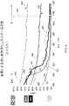
或る実施形態は、405nmから500nmのレジームで動作する青色レーザーであって、マルチモードかシングルモードのどちらかであり、溶接プロセスを実施するのに使用される青色光の源となり得る青色レーザーを利用している。図2は、青色レーザー光の吸収特性を赤外線と比較して示している。ここでは、名目上450nmである青色光(線290)が赤外線(線200)よりも高い吸収特性を有していることが明白に分かる。図2では、華氏295度(摂氏21.85度)での吸収率vs波長(nm単位)が、Ti(線401)、SS304(線402)、Ni(線403)、Sn(Tin)(線404)、Cu(線405)、Au(線406)、Ag(線407)、Al(線408)について示されており、銅を例に取ると、赤外線(4%)から青色波長(65%)への吸収率の差は、溶接プロセス始動時で16倍優れた吸収率である。吸収率でのこの改善は、溶接プロセス中のより優れた制御を可能にさせる青色の比較的低パワー/低輝度のレーザー源を用いて溶接を開始させ及び持続させることを実施可能にする。図4には、波長についての追加の吸収率が提供されており、Ti(線450)、Cu(線451)、Au(線452)、Ag(線453)、Al(線454)、Ni(線456)、及びSS(線455)を示している。450nmの波長を使用する溶接プロセスの実施形態が線460によって示されており、IR波長461での吸収率に比較してこの実施形態460の波長では材料の多くについて吸収率が良くなっていることが分かり、例えばCu、Auについては有意に向上していることが分かる。
One embodiment is a blue laser operating in a regime of 405 nm to 500 nm, which is either multimode or single mode and can be a source of blue light used to carry out the welding process. We are using. FIG. 2 shows the absorption characteristics of blue laser light in comparison with infrared rays. Here, it is clearly seen that blue light (line 290), which is nominally 450 nm, has higher absorption characteristics than infrared light (line 200). In FIG. 2, the absorptance vs. wavelength (in nm) at 295 degrees Fahrenheit (21.85 degrees Celsius) is Ti (line 401), SS304 (line 402), Ni (line 403), Sn (Tin) (line). 404), Cu (line 405), Au (line 406), Ag (line 407), Al (line 408), and taking copper as an example, infrared (4%) to blue wavelength (65%). The difference in absorption rate to) is 16 times better at the start of the welding process. This improvement in absorptivity makes it possible to initiate and sustain welds using a blue, relatively low power / low brightness laser source that allows for better control during the weld process. FIG. 4 provides additional absorptivity for wavelength, Ti (line 450), Cu (line 451), Au (line 452), Ag (line 453), Al (line 454), Ni (line 454). Line 456) and SS (line 455) are shown. An embodiment of the welding process using a wavelength of 450 nm is indicated by
本発明の実施形態は銅ベースの材料の溶接に大きな利点を見出し得るものであり、銅ベースの材料とは、銅、純銅、銅の合金、及び青色レーザー波長での好適には約400nmから約500nmでの約40%から約75%の吸収率を有するのに十分な量の銅を有しているあらゆる材料ということになる。 Embodiments of the present invention can find great advantages in welding copper-based materials, which are copper, pure copper, copper alloys, and preferably from about 400 nm to about at blue laser wavelengths. Any material that has a sufficient amount of copper to have an absorptivity of about 40% to about 75% at 500 nm.
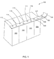
図1を見ると、電力貯蔵デバイス100の或る実施形態の概略斜視図が提供されている。この実施形態は、バスバー105によって接続されているバッテリ101、102、103、104の群を有している。バッテリは溶接区域115、114、113、112、111、110、109、108においてバスバーに接続されている。理解しておきたいこととして、好適には、青色レーザーを使用する実際のレーザー溶接部は、バスバーの下になっていて故に図1では確認できないということであってもよいし、バスバーの肉厚内の異なる位置にあってもよいし、またバスバーの幅に沿って(例えば115と114の間に見られる様に)異なる場所にあってもよいわけである。バスバー105は、例えば他のバッテリパック、電源ケーブル、又は他のデバイスへ接続できるコネクタ106を有している。青色レーザーを使用する溶接部107がバスバー105をコネクタ106へ付着させている。溶接区域に形成されている溶接部は強度のある機械的電気的接続部であり、これらの溶接区域及び各々の関連する溶接部は低い抵抗率、好適には、140mΩより低い;10mΩより低い;及び1mΩより低い抵抗率、及び約140mΩから約1mΩ、約100mΩから約50mΩ、及び約100mΩから約10mΩの抵抗率、及び約10mΩから約1mΩの抵抗率を有する。
FIG. 1 provides a schematic perspective view of an embodiment of the
レーザービームを用いて遂行され得る溶接には2つの基本的に自己生成的な溶接があり、つまり伝導溶接とキーホール溶接である。伝導溶接は、低強度(<100kW/cm2)のレーザービームを使用して2つの金属部片が一体に溶接される場合である。この場合、2つの金属部片は互いに突き合わされていてもよいし、一方の側へ重なり合っていてもよいし、全体が重なり合っていてもよい。伝導溶接はキーホール溶接ほど深く浸透する傾向はなく、伝導溶接は、概して、突合せ溶接については特徴的な「v字」形状の非常に強度のある溶接継ぎ目を現出させる。一方で、キーホール溶接は、相対的に高いレーザービーム強度(>500kW/cm2)で以て起こり、この溶接は材料の中へ深く浸透し、材料同士が重ね合わされている場合には多重の材料層を浸透することも多い。伝導モードからキーホールモードへの移行についての精密な閾値は青色レーザー源についてはまだ確定されていないが、キーホール溶接は特徴的な「v字」形状を材料の上部に有し且つ再凍結材料のほぼ平行な溝が材料の中へ深く浸透している。キーホールプロセスは、レーザーエネルギーを材料の中へ深く透過させることを金属の溶融プールの面からのレーザービームの反射に頼っている。これらの型式の溶接は何れのレーザーを用いて遂行されることもできるが、青色レーザーならこれらの溶接型式のどちらを開始させるにしても赤外線レーザーより実質的に低い閾値を有するはずであると予想される。 There are two basically self-generated welds that can be performed using a laser beam: conduction welds and keyhole welds. Conduction welding is the case where two metal pieces are integrally welded using a low-strength (<100 kW / cm 2 ) laser beam. In this case, the two metal pieces may be butted against each other, may overlap on one side, or may overlap as a whole. Conductive welds do not tend to penetrate as deeply as keyhole welds, and conducted welds generally reveal the very strong weld seams of the "v" shape that are characteristic of butt welds. On the other hand, keyhole welding occurs with a relatively high laser beam intensity (> 500kW / cm 2 ), and this welding penetrates deeply into the material and is multiple when the materials are superposed. It often penetrates the material layer. The exact threshold for the transition from conduction mode to keyhole mode has not yet been determined for the blue laser source, but keyhole welding has a characteristic "v" shape at the top of the material and is a refreeze material. Almost parallel grooves penetrate deep into the material. The keyhole process relies on the reflection of the laser beam from the surface of the metal melt pool to allow the laser energy to penetrate deep into the material. Welding of these types can be performed using any laser, but it is expected that a blue laser should have a substantially lower threshold than an infrared laser no matter which of these welding types is initiated. Will be done.
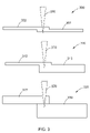
図3には、本発明の方法を使用した、貯蔵デバイスの構成要素同士を一体に溶接する場合の模式図が示されている。かくして、構成300では、450nmの波長を有する青色レーザービーム370を使用してCu箔301をCu箔302へ一体に溶接する場合が示されている。構成310では、青色レーザービーム370を使用してCu箔312をCuタブ315へ一体に溶接する場合が示されている。構成320では、レーザービーム370を使用してCuタブ322をAlバス330へ溶接する場合が示されている。
FIG. 3 shows a schematic diagram of the case where the components of the storage device are integrally welded to each other using the method of the present invention. Thus,
エネルギー貯蔵システム中に作られ得る接続部には多数の異なる型式の接続部がある。表1は、エネルギー貯蔵デバイス望ましくは高効率のエネルギー貯蔵システムを構築するのに貼り合わされることのできる材料の様々なボンド及び材料の型式の実施形態をまとめている。本レーザー動作及びシステムは、基板が薄肉材料(例えば、100μm未満、50μm未満、25μm未満、及び10μm未満、及び約100μmから約5μm、約50μmから約5μm、約76μmから約10μm、及び約50μmから約10μm)である場合に高品質溶接部を作ることができ、また厚肉材料(例えば、約0.5mm、約1mm、及びそれより厚い)について高品質溶接部を作ることができる。 There are many different types of connections that can be made in an energy storage system. Table 1 summarizes various bond and material type embodiments of the material that can be attached to the energy storage device, preferably to build a highly efficient energy storage system. In this laser operation and system, the substrate is made of thin material (eg, less than 100 μm, less than 50 μm, less than 25 μm, and less than 10 μm, and from about 100 μm to about 5 μm, from about 50 μm to about 5 μm, from about 76 μm to about 10 μm, and from about 50 μm. High quality welds can be made when the thickness is about 10 μm), and high quality welds can be made for thick materials (eg, about 0.5 mm, about 1 mm, and thicker).

表1は、左の列に掲載されている溶接部の上材料と一番上の行に沿って掲載されている溶接部の下材料でセットアップされている。こうして、異なる溶接部構成の実施形態が表中に×印で示されており、例えばCu箔(上)がCu箔(下)へ溶接される及び上のAlタブが下のCu箔へ溶接されることを示している。 Table 1 is set up with the weld top material listed in the left column and the weld bottom material listed along the top row. Thus, embodiments of different weld configurations are indicated by crosses in the table, eg, Cu foil (top) is welded to Cu foil (bottom) and the top Al tab is welded to the bottom Cu foil. Which indicates that.
薄肉材料同士を互いへ貼り合わせることは薄肉材料を厚肉材料へ貼り合わせることとは全く異なる動作であり異なる課題を提起し得る。この溶接型式に係る根本的な課題の1つは、貼り合わせ層間の熱吸収と熱拡散及び上の薄肉層を下側の厚肉層へ貼り合わせながら薄肉層に浸透してゆく能力である。本システム及び動作の実施形態は、青色レーザーシステム及び動作の特定の実施形態では、薄肉層が銅、アルミニウム、ニッケルめっきされた銅、ステンレス鋼であろうとなかろうと、上の薄肉材料層を貫いてキーホール溶接を開始させるのに十分な効率で以て、レーザーエネルギーを薄肉材料の中へ効率的に結合させることを実現可能にする。図3を見ると、薄肉材料を厚肉材料へ溶接するための青色レーザーシステム及び動作の或る実施形態の模式図がある。 Attaching thin-walled materials to each other is a completely different operation from attaching thin-walled materials to thick-walled materials, and may pose different problems. One of the fundamental issues related to this welding type is the ability to absorb and diffuse heat between the bonded layers and to penetrate the thin layer while bonding the upper thin layer to the lower thick layer. The embodiment of the system and operation penetrates the thin layer above, whether the thin layer is copper, aluminum, nickel-plated copper, stainless steel or not, in certain embodiments of the blue laser system and operation. It makes it feasible to efficiently combine laser energy into thin-walled materials with sufficient efficiency to initiate keyhole welding. Looking at FIG. 3, there is a schematic diagram of an embodiment of a blue laser system and operation for welding a thin-walled material to a thick-walled material.
本システムと共に本動作のために使用され得るレーザーは、例えば表2のパラメータ内に入るレーザーを含む。 Lasers that can be used with the system for this operation include, for example, lasers that fall within the parameters of Table 2.

また、米国特許出願第14/787,393号(3次元印刷のための装置、システム、及び方法(Devices, Systems and Methods for Three-Dimentional Printing))、米国特許出願第14/837,782号(可視ラマンレーザーを用いた材料加工のための用途、方法、及びシステム(Applications, Methods and Systems for Material Processing with Visible Raman Laser))、及び米国仮特許出願第62/193,047号(レーザー送達アドレス指定可能アレイのための用途、方法、及びシステム(Applications, Methods and Systems for a Laser Deliver Addressable Array))はそれぞれの開示全体がここに参考文献として援用されるものであって、それらに開示、教示されているレーザーシステム及びレーザーは、本発明の溶接の実施形態及び本構成要素及びコネクタの実施形態並びに本発明の他の実施形態を作るのに使用できる。 Also, US Patent Application No. 14 / 787,393 (Devices, Systems and Methods for Three-Dimental Printing), US Patent Application No. 14 / 837,782 (US Patent Application No. 14 / 787,393). Applications, methods, and systems for material processing using visible Raman lasers (Applications, Methods and Systems for Material Processing with Visible Raman Laser), and US Provisional Patent Application No. 62 / 193,047 (Laser Delivery Address Designation). Applications, methods, and systems for possible arrays (Applications, Methods and Systems for a Laser Deliver Adlessable Array) are incorporated herein by reference in their entirety and are disclosed and taught in them. Laser systems and lasers can be used to make the welding embodiments of the present invention and the embodiments of the components and connectors as well as other embodiments of the present invention.
或る実施形態では、金属を溶接するのに青色レーザーが使用されている。 In some embodiments, a blue laser is used to weld the metal.
或る実施形態では、400nmから500nmの間の波長を有する青色レーザーが材料同士を溶接するのに使用されており、例えば、箔を箔へ溶接、ここに箔は厚さ<100μm;銅箔又は銅合金箔を銅箔又は銅合金箔へ溶接;アルミニウム箔又はアルミニウム合金箔を銅箔又は銅合金箔へ溶接;アルミニウム箔又はアルミニウム合金箔をアルミニウム箔又はアルミニウム合金箔へ溶接;箔を>10μm但し<50μmである厚さを有するタブへ溶接;銅箔又は銅合金箔を銅タブ又は銅合金タブへ溶接;銅箔又は銅合金箔をアルミニウムタブ又はアルミニウム合金タブへ溶接;アルミニウム箔又はアルミニウム合金箔を銅タブ又は銅合金タブへ溶接;アルミニウム箔又はアルミニウム合金箔をアルミニウムタブ又はアルミニウム合金タブへ溶接;ニッケルめっきされた銅又はニッケルめっきされたアルミニウム及びニッケルめっきされたそれらの合金の様なニッケルめっきされた材料の溶接;ステンレス鋼箔を銅タブ又は銅合金タブへ溶接;ステンレス鋼箔をアルミニウムタブ又はアルミニウム合金タブへ溶接;タブを>100μm但し<1mmの厚さを有するバスバーへ溶接;銅タブ又は銅合金タブを銅バスバー又は銅合金バスバーへ溶接;銅タブ又は銅合金タブをアルミニウムバスバー又はアルミニウム合金バスバーへ溶接;銅タブ又は銅合金タブをニッケルめっきされた銅バスバー又はニッケルめっきされた銅合金バスバーへ溶接;銅タブ又は銅合金タブをニッケルめっきされたアルミニウムバスバー又はニッケルめっきされたアルミニウム合金バスバーへ溶接;アルミニウムタブ又はアルミニウム合金タブを銅バスバー又は銅合金バスバーへ溶接;アルミニウムタブをアルミニウムバスバーへ溶接;アルミニウムタブ又はアルミニウム合金タブをニッケルめっきされた銅バスバー又はニッケルめっきされた銅合金バスバーへ溶接;アルミニウムタブ又はアルミニウム合金タブをニッケルめっきされたアルミニウムバスバー又はニッケルめっきされたアルミニウム合金バスバーへ溶接;ステンレス鋼タブを銅バスバー又は銅合金バスバーへ溶接;ステンレス鋼タブをアルミニウムバスバー又はアルミニウム合金バスバーへ溶接;ステンレス鋼をニッケルめっきされた銅バスバー又はニッケルめっきされた銅合金バスバーへ溶接;ステンレス鋼をニッケルめっきされたアルミニウムバスバー又はニッケルめっきされたアルミニウム合金バスバーへ溶接;n>2としてn枚の銅箔又は銅合金箔を溶接;n>2としてn枚のアルミニウム箔又はアルミニウム合金箔を溶接;n>2としてn枚のステンレス鋼箔を溶接する;など、に400nmから500nmの間の波長を有する青色レーザーが使用される。 In some embodiments, a blue laser with a wavelength between 400 nm and 500 nm is used to weld the materials together, eg, weld the foil onto the foil, where the foil is <100 μm thick; copper foil or Copper alloy foil welded to copper foil or copper alloy foil; aluminum foil or aluminum alloy foil welded to copper foil or copper alloy foil; aluminum foil or aluminum alloy foil welded to aluminum foil or aluminum alloy foil; foil> 10 μm <Weld to a tab with a thickness of 50 μm; Copper foil or copper alloy foil welded to a copper tab or copper alloy tab; Copper foil or copper alloy foil welded to an aluminum tab or aluminum alloy tab; Aluminum foil or aluminum alloy foil Weld to copper tabs or copper alloy tabs; weld aluminum foil or aluminum alloy foil to aluminum tabs or aluminum alloy tabs; nickel plated copper or nickel plated aluminum and nickel plated like their alloys nickel plated Welding of the material used; Welding stainless steel foil to copper tabs or copper alloy tabs; Welding stainless steel foil to aluminum tabs or aluminum alloy tabs; Tabs> 100 μm but <welding to bus bars with a thickness of <1 mm; Copper tabs Or weld copper alloy tabs to copper bus bars or copper alloy bus bars; weld copper tabs or copper alloy tabs to aluminum bus bars or aluminum alloy bus bars; copper tabs or copper alloy tabs nickel plated copper bus bars or nickel plated copper alloys Weld to bus bars; Copper tabs or copper alloy tabs weld to nickel-plated aluminum bus bars or nickel-plated aluminum alloy bus bars; Aluminum tabs or aluminum alloy tabs weld to copper bus bars or copper alloy bus bars; Aluminum tabs to aluminum bus bars Welding; Welding aluminum tabs or aluminum alloy tabs to nickel-plated copper bus bars or nickel-plated copper alloy bus bars; Welding aluminum tabs or aluminum alloy tabs to nickel-plated aluminum bus bars or nickel-plated aluminum alloy bus bars; Weld stainless steel tabs to copper bus bars or copper alloy bus bars; weld stainless steel tabs to aluminum bus bars or aluminum alloy bus bars; weld stainless steel to nickel-plated copper bus bars or nickel-plated copper alloy bus bars; weld stainless steel to nickel Plated aluminum bath bar or nickel-plated copper Welded to luminium alloy bus bar; welded n copper foils or copper alloy foils with n> 2; welded n aluminum foils or aluminum alloy foils with n> 2; welded n stainless steel foils with n> 2. A blue laser having a wavelength between 400 nm and 500 nm is used.
銅で電気めっきされた材料、白金で電気めっきされた材料、及び他の伝導性材料で電気めっきされた材料の様な、電気めっきされた材料を青色レーザー溶接することを含め、電気めっきされた材料を、これらの材料を溶接する青色レーザー動作を使用して溶接することが構想される。 Electroplated, including blue laser welding, electroplated materials, such as copper electroplated materials, platinum electroplated materials, and other conductive materials electroplated materials. It is envisioned that the materials are welded using a blue laser operation that welds these materials.
電子記憶デバイス内の構成要素を含め、構成要素同士の溶接のための本レーザーシステム及び動作、特に青色レーザーシステム、の様々な実施形態を例示するために以下の実施例が提供されている。これらの実施例は例示が目的であり、本発明の範囲を限定するものと見なされてはならず、また他の形で本発明の範囲を限定するものでもない。 The following examples are provided to illustrate various embodiments of the present laser system and operation, in particular a blue laser system, for welding components to each other, including components within an electronic storage device. These examples are for purposes of illustration only and should not be considered as limiting the scope of the invention, nor are they otherwise limiting the scope of the invention.
実施例1 Example 1
青色レーザー溶接システムは、レーザーと、モーションシステムと、溶接ヘッドと、不活性ガス給送システム(エアナイフ又は他の制御された空気送達システムであってもよく、更には溶接ヘッドの中へ組み入れられていてもよい)と、溶接品質監視システムと、クランプシステムと、からなっている。レーザーは光ファイバーを介して溶接ヘッドへ電力を送達する。溶接ヘッドはレーザービームをコリメートし溶接されるべき部分へ再集束させる。レーザーヘッドを被加工品より上方の精密な距離にて精密なパターンで動かすために6軸ロボット又は単純な2軸ガントリーシステムの様なモーションシステムが使用されていてもよい。溶接ヘッドの被加工品からの高さは、レーザービームを溶接シームへ集束させた状態に保つうえで重要である。この青色レーザーシステムと共に使用されるはずの典型的な溶接ヘッドは、良好な溶接ビードを維持するには、+/-200μmの高さ公差を有する100mmの最終焦点距離のレンズを有することになるだろう。この構成では、レーザー/溶接システムはキーホール溶接モードで動作できるだろう。+/-400μmの高さ公差を有する200mmのより長い焦点距離のレンズを用いれば、レーザーシステムは伝導モードレジームで溶接することができるだろう。レーザービームが被加工品を横切って動かされていくと、レーザーパワーは溶接品質センサに応じて連続的に0%から100%まで変化する。センサは、溶接の品質を制御する手段として溶接部の幅を絶え間なく測定する。不活性ガスシステムは、溶接時に、溶接中の材料の酸化を防止するために必要である。不活性ガスの主たる規準は、それが溶接パドルを酸素から遮蔽することである。ヘリウム、アルゴン、アルゴン/CO2、アルゴン/水素、又は窒素の様なガスが一般に使用される。アルゴン及び又はアルゴン/CO2が好ましい、というのも、それは空気より重く、部品の周りに定着して酸素不含帯を作り出すというすばらしい仕事を果たすからである。支援ガスは様々に異なるやり方で送達され得る。溶接前、溶接後、溶接中の試料の上方、溶接中の試料の下方、溶接部へ直接、又はこれらの送達選択肢の組合せがある。クランプシステムは、溶接システムの次に最も重要な部分である。クランプは、一連のボルト又はねじを締めることによって、磁気式ホールドダウンによって、又は空気式ホールドダウンによって作動されるようになっていてもよい。これらのクランプシステムは、全てのレーザー溶接システムに普及しており、本システムもまた、レーザービームによって溶接されるべき2つ又はそれ以上の部片への強いクランプ力を保証するためにそれらを組み入れるだろう。一部の事例では、このクランプ力を加えるために、スライドと同じくローラーホイールも使用されている。他の事例では、試料部片の各面の個別クランプ及び/又はスロット付きの板が試料をしっかりと取付ジグへ保持するのに使用されている。もう1つの考察は、溶接が自己生成的でなはなく溶接継ぎ目に材料が足されることを要する事例である。これはワイヤ給送部か又は電力給送部のどちらかを用いて達成できる。充填材を要する溶接の殆どの事例はワイヤを使用するだろう。最後に、本レーザーと他のレーザー又はアークとの組合せは全ての溶接可能な材料でのより深い浸透溶接を可能にさせるだろう。溶接されるべき部品はクランプ式取付ジグへ人か又はロボットのどちらかによって動かされることができる。どちらの方法も今日では生産シナリオで使用されている。 The blue laser welding system may be a laser, a motion system, a welding head, an inert gas delivery system (air knife or other controlled air delivery system, or even incorporated into the welding head. It may consist of a welding quality monitoring system and a clamping system. The laser delivers power to the weld head via optical fiber. The weld head collimates the laser beam and refocuses it on the part to be welded. A motion system such as a 6-axis robot or a simple 2-axis gantry system may be used to move the laser head in a precise pattern at a precise distance above the workpiece. The height of the weld head from the workpiece is important for keeping the laser beam focused on the weld seam. A typical weld head that should be used with this blue laser system would have a lens with a final focal length of 100 mm with a height tolerance of +/- 200 μm to maintain a good weld bead. Let's go. In this configuration, the laser / welding system will be able to operate in keyhole welding mode. Using a lens with a longer focal length of 200 mm with a height tolerance of +/- 400 μm, the laser system could be welded in a conduction mode regime. As the laser beam is moved across the workpiece, the laser power continuously changes from 0% to 100% depending on the weld quality sensor. Sensors continuously measure the width of the weld as a means of controlling the quality of the weld. An inert gas system is needed during welding to prevent oxidation of the material during welding. The main criterion for the inert gas is that it shields the weld paddle from oxygen. Gases such as helium, argon, argon / CO2, argon / hydrogen, or nitrogen are commonly used. Argon and / or argon / CO2 are preferred because they are heavier than air and do the wonderful job of anchoring around the component and creating an oxygen-free zone. Support gas can be delivered in a variety of different ways. Before, after, and above the sample being welded, below the sample being welded, directly to the weld, or a combination of these delivery options. The clamping system is the second most important part of the welding system. The clamp may be activated by a magnetic holddown or by a pneumatic holddown by tightening a series of bolts or screws. These clamping systems are widespread in all laser welding systems, and the system also incorporates them to ensure strong clamping forces on two or more pieces to be welded by the laser beam. right. In some cases, roller wheels as well as slides are used to apply this clamping force. In other cases, individual clamps and / or slotted plates on each side of the sample piece are used to hold the sample firmly to the mounting jig. Another consideration is the case where the weld is not self-generated and requires material to be added to the weld seam. This can be achieved using either the wire feeder or the power feeder. Most cases of welds that require filler will use wires. Finally, the combination of this laser with other lasers or arcs will allow deeper penetration welding in all weldable materials. The parts to be welded can be moved to the clamp mounting jig either by humans or by robots. Both methods are used today in production scenarios.
実施例2 Example 2
或る実施形態では、バッテリの製作に使用される材料を貫いてキーホール溶接を開始して持続するのに十分な強度(>500kW/cm2)が可能な青色レーザーが採用される。 In certain embodiments, a blue laser is employed that is capable of sufficient intensity (> 500 kW / cm 2 ) to initiate and sustain keyhole welding through the material used to make the battery.
実施例3 Example 3
本システムの実施形態は、ソーラーセル相互接続部材料であって、1100アルミニウム、OFC1/4硬質銅、Cu/インバール/Cu貼り合わせ複合材、Cu/SS/Cu材料であり得るソーラーセル相互接続部を接合する、例えば溶接する、のに使用される。 Embodiments of this system are solar cell interconnects that may be 1100 aluminum, OFC1 / 4 hard copper, Cu / Invar / Cu laminated composites, Cu / SS / Cu materials. Used for joining, eg welding.
実施例4 Example 4
金属を溶接するための青色レーザー溶接システムが、青色レーザー源と、レーザービームを集束させるための及び必要であればz方向の運動を提供するための光学器組立体と、ビームを動かしてゆくための又は溶接部が作られるべき点にビームを位置決めするためのx-y走査器と、を有している。これらの構成要素は、例えばコンピュータ、コントローラ、及びその両方であってもよいとされるコントロールシステムと制御通信しているのが望ましい。 A blue laser welding system for welding metal moves the beam with a blue laser source and an optical assembly to focus the laser beam and, if necessary, to provide z-direction motion. Or has an xy scanner for positioning the beam at the point where the weld should be made. It is desirable that these components are in control communication with a control system, which may be, for example, a computer, a controller, or both.
例えば図5を見ると、本発明の方法を遂行するための青色レーザーシステムの或る実施形態の概略流れ線図が示されている。本願と同時期に出願された弁理士整理番号84366.0006(Nu 5a)を有する米国特許出願は、本溶接方法の実施形態を遂行するのに使用できるレーザーシステムの実施形態を開示及び教示しており、その全体をここに参考文献として援用する。図5は、更に、青色レーザーシステムを赤外線レーザーシステムと比較して、スポットサイズがどちらのシステムについても同じである場合の達成可能な走査体積の比較を示している。かくして、システム200内には、青色レーザービームを伝播させるためのレーザーシステム201がある。レーザーシステム201は、レーザービームを光学的送達組立体203へ送達するための光ファイバー202と光学的に通信している。このやり方では、光ファイバー202はレーザーシステム201を光学的送達組立体203と光学的通信した状態とする。光学的送達組立体203は、コリメート光学器204と可動光学器205を有している。システム200はx-y走査システム206を有している。レーザービーム及びレーザービーム経路は、x-y走査器を出て自由空間に入り、標的である例えば溶接されるべき部品に向かって進んでゆく又は方向決めされる。青色レーザーシステム200は、走査可能区域208のフットプリント、例えば一体に溶接されるべき部片への溶接動作を遂行するためにレーザービームが方向決めされ得る区域のフットプリントを作製する。図5には、比較目的のため、青色レーザーシステム200と同じスポットサイズを使用して得られるはずのIRシステム走査可能区域207が示されている。この図では、IRレーザービーム経路211IR及びIRレーザービーム212IRが青色レーザービーム経路211及び青色レーザービーム212の上に重ねて置かれている(比較目的)。この様に、どちらのシステムも同じスポットサイズを有している場合、青色レーザーシステムの走査可能区域208はIRレーザーシステムの走査可能区域207の2倍広い。矢印209は、青色レーザーシステムがIRシステムと同じスポットサイズを但し集束レンズから2倍以上離れた距離に作り出していることを説明している。この様に、青色レーザーシステムは、IRシステムより高い吸収率という利点を有しているだけでなく、同じサイズ(例えば設置面積)のシステムで、より大きい部片、より多い部片、又はより大きくより多い部片を溶接する能力を有する。
For example, FIG. 5 shows a schematic flow diagram of an embodiment of a blue laser system for carrying out the method of the invention. A US patent application with patent attorney reference number 84366.0006 (Nu 5a) filed at the same time as this application discloses and teaches embodiments of a laser system that can be used to carry out embodiments of this welding method. The whole is used here as a reference. FIG. 5 further shows a comparison of achievable scan volumes when the blue laser system is compared to the infrared laser system and the spot size is the same for both systems. Thus, within the
集束レンズシステム220は、中央のレンズがレンズシステムの焦点距離を調節するべく高速で物理的に動かされる正の構成要素か又は負の構成要素のどちらかであり得る点でズーム光学器に似ている。ビームのこの集束は、F-シータレンズシステムを通るレーザービーム走査のフラットフィールド特性を模擬するようにX-Y走査システムによるレーザービームの走査と同期される。こうして、集束システム220及び走査器206は、システム200上のコントローラ又はコントロールシステムと同期されていて制御通信している。これには、電子的に制御される集束要素がX-Y走査に遅れずについてゆくのに十分に高速であることが要件とされ、それは高速サーボシステムを用いて実現可能である。
The
本発明の実施形態の主題である又は本発明の実施形態と関連付けられる新規で画期的なプロセス、材料、性能又は他の有益な特徴及び特性の根底にある理論を提供する又は当該理論に取り組むうえで必要条件はないことを指摘しておく。それでもなお、本明細書にはこの分野の技術を更に進展させるための様々な理論が提供されている。本明細書に提言されているこれらの理論は、別途明示的に表明されていない限り、断じて、保護を与えられるべき特許請求の範囲に記載の発明の範囲を限定、制限、又は狭小化するものではない。本発明を利用するうえでこれらの理論は必要とならないかもしれないし又は実践されないかもしれない。更に理解しておきたいこととして、本発明は、本発明の方法、物品、材料、装置、及びシステムの実施形態の機能特徴を解説するための新しい理論及びこれまで知られていない理論へとつながる可能性があり、その様な後発理論は保護を与えられるべき本発明の範囲を限定するものではない。 Provides or addresses the theory underlying novel and groundbreaking processes, materials, performance or other beneficial features and properties that are the subject matter of embodiments of the invention or associated with embodiments of the invention. It should be pointed out that there are no requirements above. Nonetheless, the specification provides various theories for further advancement of technology in this field. Unless expressly stated otherwise, these theories proposed herein limit, limit, or narrow the scope of the inventions described in the claims, unless expressly stated otherwise. is not. These theories may or may not be needed in order to utilize the present invention. It should be further understood that the present invention leads to new and previously unknown theories for explaining the functional features of embodiments of the methods, articles, materials, devices and systems of the present invention. There is a possibility, and such latecomer theory does not limit the scope of the invention to which protection should be given.
本明細書に示されているシステム、機器、技法、方法、活動、及び動作の様々な実施形態は、以上に示されている活動及び分野に加え様々な他の活動のために及び様々な他の分野で使用されてもよい。加えて、これらの実施形態は、例えば、将来開発され得る他の機器又は活動と共に;及び、本明細書の教示に基づき一部が修正され得る既存の機器又は活動と共に、使用されてもよい。更に、本明細書に示されている様々な実施形態は互いと一体に異なる様々な組合せで使用されてもよい。而して、例えば、本明細書の様々な実施形態に提供されている構成は互いと一体に使用されてもよく、保護を与えられるべき本発明の範囲は、特定の実施形態、特定の実施例、又は特定の図にある実施形態に示されている特定の具現化、構成、又は配列に限定されてはならない。 Various embodiments of the systems, equipment, techniques, methods, activities, and operations set forth herein are for and various other activities in addition to the activities and disciplines set forth above. May be used in the field of. In addition, these embodiments may be used, for example, with other equipment or activities that may be developed in the future; and with existing equipment or activities that may be partially modified based on the teachings herein. In addition, the various embodiments presented herein may be used in different combinations integrally with each other. Thus, for example, the configurations provided in the various embodiments herein may be used integrally with each other, and the scope of the invention to be protected is a particular embodiment, a particular embodiment. It should not be limited to the particular embodiment, configuration, or arrangement shown in the examples or embodiments shown in the particular figure.
発明は、その精神又は本質的な特性から逸脱することなく、ここに具体的に開示されている以外の他の形態に具現化されることもできる。説明されている実施形態は、あらゆる点で、例示にすぎず制限を課すものではないと考えられるべきである。 The invention may also be embodied in other forms than specifically disclosed herein, without departing from its spirit or essential properties. The embodiments described should be considered in all respects to be illustrative only and not to impose restrictions.
100 電力貯蔵デバイス
101、102、103、104 バッテリ
105 バスバー
106 コネクタ
107 溶接部
108、109、110、111、112、113、114、115 溶接区域
200 システム
201 レーザーシステム
202 光ファイバー
203 光学的送達組立体
204 コリメート光学器
205 可動光学器
206 x-y走査システム
207 IRシステム走査可能区域
208 走査可能区域
209 青色レーザーがIRレーザーと同じスポットサイズを集束レンズから2倍以上の距離に作製することを説明する矢印
211 青色レーザービーム経路
211IR IRレーザービーム経路
212 青色レーザービーム
212IR IRレーザービーム
220 集束レンズシステム
290 青色レーザー
300 ファイバーレーザー
300、310、320 溶接部構成
301、302、312 Cu箔
315、322 Cuタブ
330 Alバス
370 青色レーザービーム
401 Ti
402 SS304
403 Ni
404 Sn(Tin)
405 Cu
406 Au
407 Ag
408 Al
450 Ti
451 Cu
452 Au
453 Ag
454 Al
455 SS
456 Ni
460 青色レーザー
461 ファイバーレーザー
100
402 SS304
403 Ni
404 Sn (Tin)
405 Cu
406 Au
407 Ag
408 Al
450 Ti
451 Cu
452 Au
453 Ag
454 Al
455 SS
456 Ni
460
Claims (38)
約5μmから約100μmの厚さを有する箔である第1の金属部片を第2の金属部片と関連付ける段階と;前記第1の金属部片及び前記第2の金属部片に向かってレーザービームを方向決めする段階と、を備え;前記レーザービームは約400nmから約500nmの範囲の波長を有し;前記第1及び第2の金属部片は溶接プロセスの始動時に前記レーザービームの約40%から約75%を吸収するものとされ;それにより前記第1及び第2の金属部片が一体に溶接されるようにする、方法。 It is a method of welding two metal pieces together.
A step of associating a first metal piece, which is a foil having a thickness of about 5 μm to about 100 μm, with a second metal piece; a laser towards the first metal piece and the second metal piece. The laser beam has a wavelength in the range of about 400 nm to about 500 nm; the first and second metal pieces are about 40 of the laser beam at the start of the welding process. % To about 75% is to be absorbed; thereby allowing the first and second metal pieces to be welded together.
第1の金属部片を第2の金属部片と関連付ける段階と;前記第1の金属部片及び前記第2の金属部片に向かってレーザービームを方向決めする段階とを備え;前記レーザービームは前記第1及び第2の金属部片の両方に当り、それにより前記第1及び第2の金属部片の両方が前記レーザービームを吸収するようにされ;前記レーザービームは約400nmから約500nmの範囲の波長を有し;前記第1の金属部片はアルミニウムであり;それにより前記第1及び第2の金属部片が一体に溶接されるようにする、方法。 It is a method of welding metal pieces together.
It comprises associating a first metal piece with a second metal piece; and directing a laser beam towards the first metal piece and the second metal piece; the laser beam. Hits both the first and second metal pieces so that both the first and second metal pieces absorb the laser beam; the laser beam is from about 400 nm to about 500 nm. A method of having a wavelength in the range of; the first metal piece is aluminum; thereby allowing the first and second metal pieces to be integrally welded together.
第1の金属部片を第2の金属部片と関連付ける段階と;前記第1の金属部片及び前記第2の金属部片に向かってレーザービームを方向決めする段階とを備え;前記レーザービームは約400nmから約500nmの範囲の波長を有し;前記第1の金属部片はアルミニウムであり;前記第2の金属部片は銅を備えており、それにより前記第1及び第2の金属部片が一体に溶接されるようにする、方法。 It is a method of welding metal pieces together.
It comprises associating a first metal piece with a second metal piece; and directing a laser beam towards the first metal piece and the second metal piece; the laser beam. Has a wavelength in the range of about 400 nm to about 500 nm; the first metal piece is aluminum; the second metal piece comprises copper, thereby the first and second metal pieces. A method of ensuring that pieces are welded together.
第1の金属部片を第2の金属部片と関連付ける段階と;前記第1の金属部片及び前記第2の金属部片に向かってレーザービームを方向決めする段階とを備え;前記レーザービームは約400nmから約500nmの範囲の波長を有し;前記第1の金属部片はアルミニウムであり;前記第2の金属部片は約50μmから約500μmの厚さを有するタブであり;前記タブは銅及び銅合金からなる群より選択される材料で作られており、それにより前記第1及び第2の金属部片が一体に溶接されるようにする、方法。 It is a method of welding metal pieces together.
It comprises associating a first metal piece with a second metal piece; and directing a laser beam towards the first metal piece and the second metal piece; the laser beam. Has a wavelength in the range of about 400 nm to about 500 nm; the first metal piece is aluminum; the second metal piece is a tab with a thickness of about 50 μm to about 500 μm; the tab. Is made of a material selected from the group consisting of copper and copper alloys, whereby the first and second metal pieces are integrally welded.
第1の金属部片を第2の金属部片と関連付ける段階と;前記第1の金属部片及び前記第2の金属部片に向かってレーザービームを方向決めする段階とを備え;前記レーザービームは約400nmから約500nmの範囲の波長を有し;前記第1の金属部片はアルミニウムであり;前記第2の金属部片は、ニッケルめっきされた材料、ニッケルめっきされた銅、ニッケルめっきされたアルミニウム、ニッケルめっきされた銅合金、ニッケルめっきされたアルミニウム合金、及びステンレス鋼からなる群より選択されており、それにより前記第1及び第2の金属部片が一体に溶接されるようにする、方法。 It is a method of welding metal pieces together.
It comprises associating a first metal piece with a second metal piece; and directing a laser beam towards the first metal piece and the second metal piece; the laser beam. Has a wavelength in the range of about 400 nm to about 500 nm; the first metal piece is aluminum; the second metal piece is a nickel-plated material, nickel-plated copper, nickel-plated. It is selected from the group consisting of aluminum, nickel-plated copper alloys, nickel-plated aluminum alloys, and stainless steel so that the first and second metal pieces are integrally welded. ,Method.
第1の金属部片を第2の金属部片と関連付ける段階と;前記第1の金属部片及び前記第2の金属部片に向かってレーザービームを方向決めする段階とを備え;前記レーザービームは約400nmから約500nmの範囲の波長を有し;前記第1の金属部片はアルミニウムであり;前記第2の金属部片は、金で電気メッキされた材料、白金で電気メッキされた材料、及び銅で電気メッキされた材料からなる群より選択されており、それにより前記第1及び第2の金属部片が一体に溶接されるようにする、方法。 It is a method of welding metal pieces together.
It comprises associating a first metal piece with a second metal piece; and directing a laser beam towards the first metal piece and the second metal piece; the laser beam. Has a wavelength in the range of about 400 nm to about 500 nm; the first metal piece is aluminum; the second metal piece is a gold electroplated material, a platinum electroplated material. , And a method of allowing the first and second metal pieces to be integrally welded together, selected from the group consisting of materials electroplated with copper.
a.接合されるべき第1の構成要素と接合されるべき第2の構成要素とを含む標的場所への既定波長を有するレーザービームの源を提供する段階と、
b.前記レーザービームが或るパターンと或る既定のレーザー強度で方向決めされることができるように走査デバイス及び集束光学器を提供する段階であって、
c.前記第1の構成要素と前記第2の構成要素の少なくとも一方は、溶接プロセスの始動時に前記レーザービームの少なくとも約45%を吸収するものである、走査デバイス及び集束光学器を提供する段階と、
d.前記第1の構成要素と前記第2の構成要素を一体に溶接するために前記標的場所へ前記レーザービームを送達して溶接部を形成する段階と、
e.前記溶接部は0.1mΩから250mΩの抵抗率を有するようにする、レーザービームを送達する段階と、
を備えている方法。 A method of joining two metal components using a blue laser beam.
a. A step of providing a source of a laser beam having a predetermined wavelength to a target location, including a first component to be joined and a second component to be joined.
b. At the stage of providing a scanning device and focusing optics so that the laser beam can be oriented with a pattern and a predetermined laser intensity.
c . The step of providing a scanning device and focusing optics, wherein the first component and at least one of the second components absorb at least about 45% of the laser beam at the start of the welding process. ,
d. A step of delivering the laser beam to the target location to form a weld in order to integrally weld the first component and the second component.
e. The step of delivering the laser beam and the step of delivering the weld so that the weld has a resistivity of 0.1 mΩ to 250 mΩ.
How to have.
a.接合されるべき第1の構成要素と接合されるべき第2の構成要素とを含む溶接部位への既定波長を有するレーザービームの源を提供する段階と、
b.前記レーザービームが或るパターンと或る既定強度で方向決めされることができるように走査デバイス及び集束光学器を提供する段階と、
c.前記第1の構成要素と前記第2の構成要素を一体に溶接するために前記溶接部位へ前記レーザービームを送達する段階であって、
d.前記強度は溶接の始動時からその完了時までを通して本質的に同じままであり、
e.レーザービームエネルギーの少なくとも45%が、溶接プロセスの始動時に、前記第1の構成要素と前記第2の構成要素の少なくとも一方に吸収される、レーザービームを送達する段階と、
を備えている方法。 A method of joining two metal components using a blue laser beam operating in CW mode, where the laser intensity at the weld does not need to be perceptibly changed.
a. A step of providing a source of a laser beam having a predetermined wavelength to a weld site including a first component to be joined and a second component to be joined, and
b. The stage of providing a scanning device and focusing optics so that the laser beam can be oriented with a pattern and a predetermined intensity, and
c. At the stage of delivering the laser beam to the welded portion in order to integrally weld the first component and the second component.
d. The strength remains essentially the same from the start of the weld to its completion.
e. A step of delivering a laser beam, in which at least 45% of the laser beam energy is absorbed by at least one of the first component and the second component at the start of the welding process .
How to have.
第1の金属部片を第2の金属部片と関連付ける段階と;前記第1の金属部片及び前記第2の金属部片に向かってレーザービームを方向決めする段階と、を備え;前記レーザービームは約400nmから約500nmの範囲の波長を有し;前記第1及び第2の金属部片は溶接プロセスの始動時に前記レーザービームの約40%から約75%を吸収するものとされ;前記第2の金属部片は、ニッケルめっきされた材料、ニッケルめっきされた銅、ニッケルめっきされたアルミニウム、ニッケルめっきされた銅合金、ニッケルめっきされたアルミニウム合金、及びステンレス鋼からなる群より選択されており、それにより前記第1及び第2の金属部片が一体に溶接されるようにする、方法。 It is a method of welding two metal pieces together.
It comprises associating a first metal piece with a second metal piece; and directing a laser beam towards the first metal piece and the second metal piece; the laser. The beam has a wavelength in the range of about 400 nm to about 500 nm; the first and second metal pieces are supposed to absorb about 40% to about 75% of the laser beam at the start of the welding process ; said. The second metal piece is selected from the group consisting of nickel-plated material, nickel-plated copper, nickel-plated aluminum, nickel-plated copper alloy, nickel-plated aluminum alloy, and stainless steel. A method of allowing the first and second metal pieces to be integrally welded together.
第1の金属部片を第2の金属部片と関連付ける段階と;前記第1の金属部片及び前記第2の金属部片に向かってレーザービームを方向決めする段階と、を備え;前記レーザービームは約400nmから約500nmの範囲の波長を有し;前記第1及び第2の金属部片は溶接プロセスの始動時に前記レーザービームの約40%から約75%を吸収するものとされ;前記第2の金属部片は、金で電気メッキされた材料、白金で電気メッキされた材料、及び銅で電気メッキされた材料からなる群より選択されており、それにより前記第1及び第2の金属部片が一体に溶接されるようにする、方法。 It is a method of welding two metal pieces together.
It comprises associating a first metal piece with a second metal piece; and directing a laser beam towards the first metal piece and the second metal piece; the laser. The beam has a wavelength in the range of about 400 nm to about 500 nm; the first and second metal pieces are supposed to absorb about 40% to about 75% of the laser beam at the start of the welding process ; said. The second metal piece is selected from the group consisting of a material electroplated with gold, a material electroplated with platinum, and a material electroplated with copper, thereby the first and second pieces. A method of making metal pieces weld together.
Priority Applications (2)
| Application Number | Priority Date | Filing Date | Title |
|---|---|---|---|
| JP2022051337A JP7392022B2 (en) | 2016-04-29 | 2022-03-28 | Visible laser welding of electronic packaging, automotive electrical equipment, batteries, and other components |
| JP2023198006A JP2024019199A (en) | 2016-04-29 | 2023-11-22 | Visible laser welding of electronic packaging, automotive electrical equipment, batteries, and other components |
Applications Claiming Priority (3)
| Application Number | Priority Date | Filing Date | Title |
|---|---|---|---|
| US201662329830P | 2016-04-29 | 2016-04-29 | |
| US62/329,830 | 2016-04-29 | ||
| PCT/US2017/030175 WO2017190042A1 (en) | 2016-04-29 | 2017-04-28 | Visible laser welding of electronic packaging, automotive electrics, battery and other components |
Related Child Applications (1)
| Application Number | Title | Priority Date | Filing Date |
|---|---|---|---|
| JP2022051337A Division JP7392022B2 (en) | 2016-04-29 | 2022-03-28 | Visible laser welding of electronic packaging, automotive electrical equipment, batteries, and other components |
Publications (3)
| Publication Number | Publication Date |
|---|---|
| JP2019514694A JP2019514694A (en) | 2019-06-06 |
| JP2019514694A5 JP2019514694A5 (en) | 2020-01-16 |
| JP7050002B2 true JP7050002B2 (en) | 2022-04-07 |
Family
ID=60161160
Family Applications (3)
| Application Number | Title | Priority Date | Filing Date |
|---|---|---|---|
| JP2018556818A Active JP7050002B2 (en) | 2016-04-29 | 2017-04-28 | Visible laser welding of electronic packaging, automotive electrical equipment, batteries, and other components |
| JP2022051337A Active JP7392022B2 (en) | 2016-04-29 | 2022-03-28 | Visible laser welding of electronic packaging, automotive electrical equipment, batteries, and other components |
| JP2023198006A Pending JP2024019199A (en) | 2016-04-29 | 2023-11-22 | Visible laser welding of electronic packaging, automotive electrical equipment, batteries, and other components |
Family Applications After (2)
| Application Number | Title | Priority Date | Filing Date |
|---|---|---|---|
| JP2022051337A Active JP7392022B2 (en) | 2016-04-29 | 2022-03-28 | Visible laser welding of electronic packaging, automotive electrical equipment, batteries, and other components |
| JP2023198006A Pending JP2024019199A (en) | 2016-04-29 | 2023-11-22 | Visible laser welding of electronic packaging, automotive electrical equipment, batteries, and other components |
Country Status (6)
| Country | Link |
|---|---|
| US (1) | US20170341144A1 (en) |
| EP (1) | EP3448622B1 (en) |
| JP (3) | JP7050002B2 (en) |
| KR (3) | KR20210134087A (en) |
| CN (1) | CN109715339A (en) |
| WO (1) | WO2017190042A1 (en) |
Families Citing this family (42)
| Publication number | Priority date | Publication date | Assignee | Title |
|---|---|---|---|---|
| US10971896B2 (en) | 2013-04-29 | 2021-04-06 | Nuburu, Inc. | Applications, methods and systems for a laser deliver addressable array |
| US10562132B2 (en) | 2013-04-29 | 2020-02-18 | Nuburu, Inc. | Applications, methods and systems for materials processing with visible raman laser |
| US11646549B2 (en) | 2014-08-27 | 2023-05-09 | Nuburu, Inc. | Multi kW class blue laser system |
| US11612957B2 (en) | 2016-04-29 | 2023-03-28 | Nuburu, Inc. | Methods and systems for welding copper and other metals using blue lasers |
| CA3052155A1 (en) | 2017-01-31 | 2018-08-09 | Nuburu, Inc. | Methods and systems for welding copper using blue laser |
| JP7088958B2 (en) | 2017-04-21 | 2022-06-21 | ヌブル インク | Multi-clad optical fiber |
| CN110999000B (en) | 2017-06-13 | 2021-10-08 | 努布鲁有限公司 | High-density wavelength beam combined laser system |
| WO2018235637A1 (en) * | 2017-06-21 | 2018-12-27 | 古河電気工業株式会社 | Wire connection structure |
| CN108393585A (en) * | 2018-04-17 | 2018-08-14 | 淮阴师范学院 | Interval adjustable multi-beam laser mash welder and end cover of filter flexible automation laser spot welding production line |
| CN117031615A (en) | 2018-05-04 | 2023-11-10 | 努布鲁有限公司 | Three-clad optical fiber |
| JP2019197820A (en) * | 2018-05-10 | 2019-11-14 | 株式会社島津製作所 | Laser device |
| EP3807041A4 (en) * | 2018-07-19 | 2022-04-06 | IPG Photonics Corporation | Systems and methods for monitoring and/or controlling wobble-processing using inline coherent imaging (ici) |
| CN116638102A (en) * | 2018-08-24 | 2023-08-25 | 努布鲁有限公司 | Blue Laser Metal Additive Manufacturing System |
| JP7347432B2 (en) * | 2018-09-03 | 2023-09-20 | 住友電気工業株式会社 | Welded structure of metal members and manufacturing method of welded structure of metal members |
| WO2020107030A1 (en) | 2018-11-23 | 2020-05-28 | Nuburu, Inc | Multi-wavelength visible laser source |
| IT201800021022A1 (en) | 2018-12-24 | 2020-06-24 | Comau Spa | "Procedure for monitoring the quality of a weld, relative welding station and IT product" |
| WO2020142458A1 (en) * | 2018-12-30 | 2020-07-09 | Nuburu, Inc. | Methods and systems for welding copper and other metals using blue lasers |
| CN209550932U (en) * | 2019-01-30 | 2019-10-29 | 宁德时代新能源科技股份有限公司 | Weld assembly and battery modules |
| EP3917718A4 (en) * | 2019-02-02 | 2022-12-07 | Nuburu, Inc. | High reliability high power, high brightness blue laser diode systems and methods of making |
| CN110340521A (en) * | 2019-07-19 | 2019-10-18 | 中国第一汽车股份有限公司 | A kind of method for laser welding of copper and mickel |
| DE102019211070B3 (en) * | 2019-07-25 | 2020-12-10 | Robert Bosch Gmbh | Manufacturing process for welding a copper conductor to a workpiece, workpiece and vehicle |
| CN110471191B (en) * | 2019-08-02 | 2021-03-30 | 腾景科技股份有限公司 | Novel multiband light source for material processing and implementation method thereof |
| DE102019214891A1 (en) * | 2019-09-27 | 2021-04-01 | Trumpf Laser- Und Systemtechnik Gmbh | Process for laser soldering, in particular of steel body parts |
| EP3797890B1 (en) * | 2019-09-30 | 2024-03-27 | Nexans | Method for the production of thin-walled hollow profiles with small diameters made from non-ferrous metals |
| EP3797891B1 (en) | 2019-09-30 | 2023-08-02 | Nexans | Method for the continuous production of thin-walled hollow profiles with small diameters, corrugated in sections and made from non-ferrous metals |
| DE102019216070A1 (en) * | 2019-10-18 | 2021-04-22 | Trumpf Laser- Und Systemtechnik Gmbh | Method for processing a lithium foil or a metal foil coated with lithium by means of a laser beam |
| CN114829057B (en) * | 2019-12-25 | 2024-03-05 | 古河电气工业株式会社 | Method for welding metal foil |
| CA3163159A1 (en) * | 2019-12-30 | 2021-07-08 | Mathew Finuf | Methods and systems for reducing hazardous byproduct from welding metals using lasers |
| US20220126400A1 (en) | 2020-10-22 | 2022-04-28 | Ferrari S.P.A. | Method to execute a weld of an electrode of a cell which is part of a battery |
| KR20220056637A (en) | 2020-10-28 | 2022-05-06 | 삼성에스디아이 주식회사 | Laser welding method and laser welding devicefor secondary battery |
| CN112355477B (en) * | 2020-11-18 | 2024-01-19 | 苏州松控电子科技有限公司 | Electrode plate welding method for electrolytic capacitor |
| EP4269661A4 (en) * | 2020-12-24 | 2024-03-06 | Nissan Motor | Laser welding-use aluminum alloy member |
| GB2623441A (en) * | 2021-03-03 | 2024-04-17 | Jaguar Land Rover Ltd | Components for Batteries |
| GB2605408A (en) * | 2021-03-31 | 2022-10-05 | Jaguar Land Rover Ltd | Laser welding position determination |
| GB2605415A (en) * | 2021-03-31 | 2022-10-05 | Jaguar Land Rover Ltd | Methods for Welding Components of Battery Modules |
| GB2605407A (en) * | 2021-03-31 | 2022-10-05 | Jaguar Land Rover Ltd | Methods for welding components of battery modules |
| GB2605410A (en) * | 2021-03-31 | 2022-10-05 | Jaguar Land Rover Ltd | Methods for welding components of battery modules |
| CN113146037B (en) * | 2021-04-16 | 2023-06-30 | 北京工业大学 | Laser high-speed spiral spot welding method for aluminum/copper dissimilar material sheet |
| EP4348759A1 (en) * | 2021-05-27 | 2024-04-10 | Jaguar Land Rover Limited | Components for batteries |
| CN113937429A (en) * | 2021-10-14 | 2022-01-14 | 湖北亿纬动力有限公司 | Negative electrode connecting method and device |
| WO2023085336A1 (en) * | 2021-11-10 | 2023-05-19 | 古河電気工業株式会社 | Welding method, welding device, and metal laminate |
| JP7456559B1 (en) | 2022-12-02 | 2024-03-27 | Jfeスチール株式会社 | Stainless steel and copper joined body and its manufacturing method, and stainless steel and copper joining method |
Citations (4)
| Publication number | Priority date | Publication date | Assignee | Title |
|---|---|---|---|---|
| JP2006094600A (en) | 2004-09-22 | 2006-04-06 | Miyachi Technos Corp | Rotor wire connection method |
| JP2011018823A (en) | 2009-07-10 | 2011-01-27 | Miyachi Technos Corp | Wire bonding method, and laser welding apparatus for wire bonding |
| US20150136840A1 (en) | 2013-11-21 | 2015-05-21 | Medtronic, Inc. | Method of joining stacks of thin metal foil layers |
| US20160067780A1 (en) | 2013-04-29 | 2016-03-10 | Nuburu, Inc. | Devices, systems and methods for three-dimensional printing |
Family Cites Families (100)
| Publication number | Priority date | Publication date | Assignee | Title |
|---|---|---|---|---|
| US3402254A (en) * | 1966-12-02 | 1968-09-17 | Texas Instruments Inc | Composite electrical bus bar |
| JPS4942538A (en) * | 1972-08-30 | 1974-04-22 | ||
| US4187408A (en) * | 1975-10-24 | 1980-02-05 | Union Carbide Corporation | Method for laser seam welding of moving workpieces |
| US4185185A (en) * | 1975-10-24 | 1980-01-22 | Union Carbide Corporation | Laser welding |
| IT1119679B (en) * | 1979-03-05 | 1986-03-10 | Fiat Auto Spa | EQUIPMENT FOR CARRYING OUT TREATMENTS ON METAL PIECES BY MEANS |
| EP0218069A1 (en) * | 1985-09-19 | 1987-04-15 | Siemens Aktiengesellschaft | Laser light welding process |
| US4679198A (en) * | 1986-04-04 | 1987-07-07 | North American Philips Corporation | Solid-state tunable laser |
| US4879449A (en) * | 1987-01-30 | 1989-11-07 | Duley Walter W | Means of enhancing laser processing efficiency of metals |
| US4857699A (en) * | 1987-01-30 | 1989-08-15 | Duley Walter W | Means of enhancing laser processing efficiency of metals |
| US5124973A (en) * | 1988-02-04 | 1992-06-23 | Pioneer Electronic Corporation | Tilt control mechanism |
| FR2637210B1 (en) * | 1988-09-30 | 1990-11-09 | Thomson Hybrides Microondes | LASER BEAM WELDING METHOD OF TWO METAL PARTS, AND ELECTRONIC BOX WELDED BY THIS METHOD |
| JPH03106578A (en) * | 1989-09-20 | 1991-05-07 | Sumitomo Special Metals Co Ltd | Manufacture of spot shaped partial clad material |
| US5129884A (en) * | 1990-01-16 | 1992-07-14 | Dysarz Edward D | Trap in barrel one handed retracted intervenous catheter device |
| US5027360A (en) * | 1990-06-13 | 1991-06-25 | Stanford University | High power continuous wave injection-locked solid state laser |
| JPH0489190A (en) * | 1990-07-31 | 1992-03-23 | Nippondenso Co Ltd | Method for joining insulated electric wire and terminal |
| US5085122A (en) * | 1991-02-07 | 1992-02-04 | The United States Of America As Represented By The Secretary Of The Navy | Firing assembly for stored energy launcher |
| GB9200622D0 (en) * | 1992-01-13 | 1992-03-11 | Duley Walter W | Improved means of co2 laser welding of a1 7075 |
| US5393482A (en) * | 1993-10-20 | 1995-02-28 | United Technologies Corporation | Method for performing multiple beam laser sintering employing focussed and defocussed laser beams |
| US5517059A (en) * | 1994-04-26 | 1996-05-14 | Delco Electronics Corp. | Electron and laser beam welding apparatus |
| US5502292A (en) * | 1994-08-04 | 1996-03-26 | Midwest Research Institute | Method for laser welding ultra-thin metal foils |
| US5500503A (en) * | 1994-08-04 | 1996-03-19 | Midwest Research Institute | Simultaneous laser cutting and welding of metal foil to edge of a plate |
| US5932119A (en) * | 1996-01-05 | 1999-08-03 | Lazare Kaplan International, Inc. | Laser marking system |
| DE19606731C2 (en) * | 1996-02-23 | 2000-12-07 | Sinterstahl Gmbh | Process for welding scattered sintered friction linings |
| US5578227A (en) * | 1996-11-22 | 1996-11-26 | Rabinovich; Joshua E. | Rapid prototyping system |
| US5940037A (en) * | 1997-04-29 | 1999-08-17 | The Whitaker Corporation | Stacked patch antenna with frequency band isolation |
| JPH1177348A (en) * | 1997-08-29 | 1999-03-23 | Canon Inc | Welding method and photovoltaic element |
| US6060685A (en) * | 1997-10-23 | 2000-05-09 | Trw Inc. | Method for monitoring laser weld quality via plasma light intensity measurements |
| US5987043A (en) * | 1997-11-12 | 1999-11-16 | Opto Power Corp. | Laser diode arrays with offset components |
| JPH11243224A (en) * | 1997-12-26 | 1999-09-07 | Canon Inc | Photovoltaic element module, manufacture thereof and non-contact treatment |
| US6172327B1 (en) * | 1998-07-14 | 2001-01-09 | General Electric Company | Method for laser twist welding of compressor blisk airfoils |
| US6326585B1 (en) * | 1998-07-14 | 2001-12-04 | General Electric Company | Apparatus for laser twist weld of compressor blisks airfoils |
| US7045015B2 (en) * | 1998-09-30 | 2006-05-16 | Optomec Design Company | Apparatuses and method for maskless mesoscale material deposition |
| CA2419944A1 (en) * | 2000-08-21 | 2002-02-28 | National Research Council Of Canada | Methods for creating optical structures in dielectrics using controlled energy deposition |
| US6479168B2 (en) * | 2001-04-03 | 2002-11-12 | The Regents Of The University Of Michigan | Alloy based laser welding |
| US20020149137A1 (en) * | 2001-04-12 | 2002-10-17 | Bor Zeng Jang | Layer manufacturing method and apparatus using full-area curing |
| US7616986B2 (en) * | 2001-05-07 | 2009-11-10 | University Of Washington | Optical fiber scanner for performing multimodal optical imaging |
| EP1414612B1 (en) * | 2001-08-07 | 2009-12-23 | Fraunhofer-Gesellschaft zur Förderung der angewandten Forschung e.V. | Laser beam welding method |
| US6714581B2 (en) * | 2001-10-01 | 2004-03-30 | Christopher J. Corcoran | Compact phase locked laser array and related techniques |
| US7358157B2 (en) * | 2002-03-27 | 2008-04-15 | Gsi Group Corporation | Method and system for high-speed precise laser trimming, scan lens system for use therein and electrical device produced thereby |
| US6670574B1 (en) * | 2002-07-31 | 2003-12-30 | Unitek Miyachi Corporation | Laser weld monitor |
| DE10306235B4 (en) * | 2003-02-14 | 2005-02-03 | Daimlerchrysler Ag | Method and arrangement for resistance seam welding of a film and at least one film carrier of a fuel cell system |
| US6906281B2 (en) * | 2003-03-03 | 2005-06-14 | Dana Corporation | Method for laser welding of metal |
| US6875949B2 (en) * | 2003-03-19 | 2005-04-05 | Edison Welding Institute | Method of welding titanium and titanium based alloys to ferrous metals |
| US20070170158A1 (en) * | 2003-09-09 | 2007-07-26 | Greig Christian F | System and method for laser welding foils |
| US7034992B2 (en) * | 2003-10-08 | 2006-04-25 | Northrop Grumman Corporation | Brightness enhancement of diode light sources |
| JP2005347415A (en) * | 2004-06-01 | 2005-12-15 | Miyachi Technos Corp | Electric part mounting method |
| US20080035615A1 (en) * | 2004-09-16 | 2008-02-14 | Y. Norman Zhou | Lap welding of steel articles having a corrosion resisting metallic coating |
| JP2006095602A (en) * | 2004-09-27 | 2006-04-13 | Dana Corp | Method of welding galvanized steel component |
| US20060207976A1 (en) * | 2005-01-21 | 2006-09-21 | Bovatsek James M | Laser material micromachining with green femtosecond pulses |
| US20090283505A1 (en) * | 2005-07-13 | 2009-11-19 | Dr Industries | Interface suspension for alloy based laser welding |
| DE102006042280A1 (en) * | 2005-09-08 | 2007-06-06 | IMRA America, Inc., Ann Arbor | Transparent material scribing comprises using single scan of focused beam of ultrashort laser pulses to simultaneously create surface groove in material and modified region(s) within bulk of material |
| FR2893872B1 (en) * | 2005-11-25 | 2008-10-17 | Air Liquide | CUTTING PROCESS WITH FIBER STEEL LASER C-MN |
| JP2007265962A (en) * | 2006-02-28 | 2007-10-11 | Hitachi Ltd | Method of laser welding, manufacturing method of control unit, and vehicular control unit |
| US7515346B2 (en) * | 2006-07-18 | 2009-04-07 | Coherent, Inc. | High power and high brightness diode-laser array for material processing applications |
| DE102009013110B4 (en) * | 2008-03-20 | 2018-02-08 | Denso Corporation | Laser welding structure and laser welding process |
| CN101990729B (en) * | 2008-03-31 | 2013-02-27 | 伊雷克托科学工业股份有限公司 | Combining multiple laser beams to form high repetition rate, high average power polarized laser beam |
| US8571368B2 (en) * | 2010-07-21 | 2013-10-29 | Foro Energy, Inc. | Optical fiber configurations for transmission of laser energy over great distances |
| GB0816308D0 (en) * | 2008-09-05 | 2008-10-15 | Mtt Technologies Ltd | Optical module |
| WO2010068804A1 (en) * | 2008-12-10 | 2010-06-17 | Boston Scientific Scimed, Inc. | Method of forming a joint between a titanium alloy member and a steel alloy member and medical device comprising said joint |
| CN101527335B (en) * | 2009-01-14 | 2011-11-02 | 普乐新能源(蚌埠)有限公司 | Method for preparing thin film solar cell by green laser |
| US8080749B2 (en) * | 2009-03-04 | 2011-12-20 | Niles America Wintech, Inc. | Switch and welding method of same |
| DE102009016805B4 (en) * | 2009-04-09 | 2014-04-03 | Alanod Gmbh & Co. Kg | Method for laser welding a composite material with a component |
| JP2010253500A (en) * | 2009-04-23 | 2010-11-11 | Sumitomo Electric Ind Ltd | Laser welding method |
| US20120055909A1 (en) * | 2009-05-15 | 2012-03-08 | Hideaki Miyake | Method of laser-welding and method of manufacturing battery including the same |
| JP5479024B2 (en) * | 2009-10-27 | 2014-04-23 | パナソニック株式会社 | Joining method and joining apparatus |
| KR101084220B1 (en) * | 2009-10-30 | 2011-11-17 | 에스비리모티브 주식회사 | Terminal unit for secondary battery and manufacturing method thereof |
| US8598523B2 (en) * | 2009-11-13 | 2013-12-03 | Sciaky, Inc. | Electron beam layer manufacturing using scanning electron monitored closed loop control |
| KR20110055255A (en) * | 2009-11-19 | 2011-05-25 | 에스비리모티브 주식회사 | Bus bar and battery module with the same |
| US8441718B2 (en) * | 2009-11-23 | 2013-05-14 | Lockheed Martin Corporation | Spectrally beam combined laser system and method at eye-safer wavelengths |
| US9352424B2 (en) * | 2009-12-04 | 2016-05-31 | Nippon Steel & Sumitomo Metal Corporation | Butt welding joint using high-energy density beam |
| WO2011082128A1 (en) * | 2009-12-28 | 2011-07-07 | Productive Researsh Llc. | Processes for welding composite materials and articles therefrom |
| JP2011143457A (en) * | 2010-01-15 | 2011-07-28 | Tyco Electronics Japan Kk | Laser welding structure |
| KR101097227B1 (en) * | 2010-02-08 | 2011-12-21 | 에스비리모티브 주식회사 | Battery module and the manufacturing method thereof |
| CN101771142B (en) * | 2010-02-10 | 2012-09-19 | 力佳电源科技(深圳)有限公司 | Tab material of flexible-packaging lithium battery as well as electroplating method and application method thereof |
| DE112011100812T5 (en) * | 2010-03-05 | 2013-03-07 | TeraDiode, Inc. | System and method for wavelength beam combination |
| CN101997047B (en) * | 2010-04-20 | 2012-10-03 | 常州天合光能有限公司 | Circuit laminated structure of photovoltaic assembly |
| JP5186528B2 (en) * | 2010-04-23 | 2013-04-17 | 日本発條株式会社 | Conductive member and manufacturing method thereof |
| US9175568B2 (en) * | 2010-06-22 | 2015-11-03 | Honeywell International Inc. | Methods for manufacturing turbine components |
| JP5232840B2 (en) * | 2010-09-03 | 2013-07-10 | 日立ビークルエナジー株式会社 | Secondary battery and manufacturing method thereof |
| US20130162952A1 (en) * | 2010-12-07 | 2013-06-27 | Laser Light Engines, Inc. | Multiple Laser Projection System |
| GB2487437A (en) * | 2011-01-24 | 2012-07-25 | Univ Southampton | A first resonant optical fiber cavity and an second resonant enhancement cavity arranged in the first cavity. |
| US9025635B2 (en) * | 2011-01-24 | 2015-05-05 | Soraa Laser Diode, Inc. | Laser package having multiple emitters configured on a support member |
| EP2683522A4 (en) * | 2011-03-11 | 2015-06-03 | Univ Columbia | Methods, devices, systems for joining materials and resulting articles |
| US8894721B2 (en) * | 2011-03-23 | 2014-11-25 | GM Global Technology Operations LLC | Beam welding of a multi-sheet work stack with a single common welding interface |
| US8535395B2 (en) * | 2011-03-23 | 2013-09-17 | GM Global Technology Operations LLC | Beam welding of a multi-sheet work stack having a reduced thickness feature |
| JP5252026B2 (en) * | 2011-05-10 | 2013-07-31 | パナソニック株式会社 | Laser welding apparatus and laser welding method |
| DK2710654T3 (en) * | 2011-05-19 | 2015-04-27 | Super B B V | Connecting device to cells in a battery |
| US8824513B2 (en) * | 2011-06-14 | 2014-09-02 | Bae Systems Information And Electronic Systems Integration Inc. | Method for beam combination by seeding stimulated brillouin scattering in optical fiber |
| CN104412357B (en) * | 2012-04-17 | 2017-09-22 | 环球太阳能公司 | The interconnection of product body thin film solar energy structure cell battery |
| KR101449118B1 (en) * | 2012-08-31 | 2014-10-10 | 주식회사 포스코 | Method for laser welding and welded metal using the same |
| WO2014129221A1 (en) * | 2013-02-24 | 2014-08-28 | 古河電気工業株式会社 | Metal member, terminal, electric wire connection structure, and method of manufacturing terminal |
| US20140305910A1 (en) * | 2013-03-27 | 2014-10-16 | Ipg Photonics Corporation | System and Method Utilizing Fiber Lasers for Titanium Welding Using an Argon Cover Gas |
| US10562132B2 (en) * | 2013-04-29 | 2020-02-18 | Nuburu, Inc. | Applications, methods and systems for materials processing with visible raman laser |
| CN103331511B (en) * | 2013-07-03 | 2014-07-02 | 林青云 | Electric resistance welding method, and electrode welding head used in electric resistance welding method |
| KR101677317B1 (en) * | 2013-07-03 | 2016-11-17 | 주식회사 포스코 | Method for manufacturing electrical steel sheet laminated core for reducing core loss and increasing strength and laminated core produced by the same |
| KR101554361B1 (en) * | 2013-07-09 | 2015-09-18 | 주식회사 엘지화학 | A welding method of different metal, different metal busbar manufactured by the same and secondary battery comprising the same |
| JP6354415B2 (en) * | 2013-08-14 | 2018-07-11 | 富士電機株式会社 | Laser welding machine and laser welding method using the same |
| CN106232283B (en) * | 2014-02-28 | 2019-03-29 | Ipg光子公司 | It is processed using the multi-beam laser of different wave length and/or multiple laser beams in pulse duration |
| JP5982652B2 (en) * | 2014-04-15 | 2016-08-31 | パナソニックIpマネジメント株式会社 | Dissimilar metal joint |
| US9770790B2 (en) * | 2015-07-30 | 2017-09-26 | Ford Global Technologies, Llc | Metal sheet laser welding clamp |
-
2017
- 2017-04-28 WO PCT/US2017/030175 patent/WO2017190042A1/en active Application Filing
- 2017-04-28 US US15/581,928 patent/US20170341144A1/en active Pending
- 2017-04-28 KR KR1020217035586A patent/KR20210134087A/en not_active IP Right Cessation
- 2017-04-28 KR KR1020187034620A patent/KR20190012175A/en active Application Filing
- 2017-04-28 CN CN201780040943.9A patent/CN109715339A/en active Pending
- 2017-04-28 JP JP2018556818A patent/JP7050002B2/en active Active
- 2017-04-28 KR KR1020237019459A patent/KR20230090371A/en not_active Application Discontinuation
- 2017-04-28 EP EP17790567.6A patent/EP3448622B1/en active Active
-
2022
- 2022-03-28 JP JP2022051337A patent/JP7392022B2/en active Active
-
2023
- 2023-11-22 JP JP2023198006A patent/JP2024019199A/en active Pending
Patent Citations (4)
| Publication number | Priority date | Publication date | Assignee | Title |
|---|---|---|---|---|
| JP2006094600A (en) | 2004-09-22 | 2006-04-06 | Miyachi Technos Corp | Rotor wire connection method |
| JP2011018823A (en) | 2009-07-10 | 2011-01-27 | Miyachi Technos Corp | Wire bonding method, and laser welding apparatus for wire bonding |
| US20160067780A1 (en) | 2013-04-29 | 2016-03-10 | Nuburu, Inc. | Devices, systems and methods for three-dimensional printing |
| US20150136840A1 (en) | 2013-11-21 | 2015-05-21 | Medtronic, Inc. | Method of joining stacks of thin metal foil layers |
Also Published As
| Publication number | Publication date |
|---|---|
| WO2017190042A1 (en) | 2017-11-02 |
| JP7392022B2 (en) | 2023-12-05 |
| KR20210134087A (en) | 2021-11-08 |
| JP2024019199A (en) | 2024-02-08 |
| KR20230090371A (en) | 2023-06-21 |
| JP2019514694A (en) | 2019-06-06 |
| EP3448622A1 (en) | 2019-03-06 |
| US20170341144A1 (en) | 2017-11-30 |
| EP3448622B1 (en) | 2023-11-15 |
| CN109715339A (en) | 2019-05-03 |
| KR20190012175A (en) | 2019-02-08 |
| EP3448622A4 (en) | 2020-04-08 |
| JP2022095743A (en) | 2022-06-28 |
Similar Documents
| Publication | Publication Date | Title |
|---|---|---|
| JP7050002B2 (en) | Visible laser welding of electronic packaging, automotive electrical equipment, batteries, and other components | |
| JP6911153B2 (en) | Methods and systems for welding copper using a blue laser | |
| US20090130482A1 (en) | Titanium aluminium component | |
| JP2009500177A (en) | System and method for laser resistance hybrid welding | |
| US11446764B2 (en) | Laser welding stacked foils | |
| JP2016030280A (en) | Method and apparatus for laser welding of metal foil | |
| US11203085B2 (en) | Method and apparatus for laser welding | |
| JP6238766B2 (en) | Welding equipment | |
| CN113543921A (en) | Method and system for welding copper and other metals using blue laser | |
| WO2023157809A1 (en) | Laser welding method | |
| WO2023157810A1 (en) | Laser welding method and metal joined body | |
| RO137959A2 (en) | Laser welding method for welding contacts between the cells of electric batteries made of heterogeneous materials cu-ai, using a rigid contact-keeping device and thermal imaging surveillance | |
| WO2022270595A1 (en) | Welding method, metal laminate, electrical component, and electrical product | |
| Kim et al. | Review on Ultrasonic and Laser Welding Technologies of Multi-Layer Thin Foils for the Lithium-Ion Pouch Cell Manufacturing | |
| Shannon | Spot and Seam Welding Applications Using an Nd: YAG Laser | |
| CN113878234A (en) | Laser welding method and device for double-layer tab and lithium battery |
Legal Events
| Date | Code | Title | Description |
|---|---|---|---|
| A521 | Request for written amendment filed |
Free format text: JAPANESE INTERMEDIATE CODE: A523 Effective date: 20190104 |
|
| A621 | Written request for application examination |
Free format text: JAPANESE INTERMEDIATE CODE: A621 Effective date: 20191129 |
|
| A521 | Request for written amendment filed |
Free format text: JAPANESE INTERMEDIATE CODE: A523 Effective date: 20191202 |
|
| A131 | Notification of reasons for refusal |
Free format text: JAPANESE INTERMEDIATE CODE: A131 Effective date: 20200901 |
|
| A601 | Written request for extension of time |
Free format text: JAPANESE INTERMEDIATE CODE: A601 Effective date: 20201201 |
|
| A601 | Written request for extension of time |
Free format text: JAPANESE INTERMEDIATE CODE: A601 Effective date: 20210201 |
|
| A521 | Request for written amendment filed |
Free format text: JAPANESE INTERMEDIATE CODE: A523 Effective date: 20210301 |
|
| A131 | Notification of reasons for refusal |
Free format text: JAPANESE INTERMEDIATE CODE: A131 Effective date: 20210525 |
|
| A601 | Written request for extension of time |
Free format text: JAPANESE INTERMEDIATE CODE: A601 Effective date: 20210825 |
|
| A601 | Written request for extension of time |
Free format text: JAPANESE INTERMEDIATE CODE: A601 Effective date: 20211025 |
|
| A521 | Request for written amendment filed |
Free format text: JAPANESE INTERMEDIATE CODE: A523 Effective date: 20211124 |
|
| TRDD | Decision of grant or rejection written | ||
| A01 | Written decision to grant a patent or to grant a registration (utility model) |
Free format text: JAPANESE INTERMEDIATE CODE: A01 Effective date: 20220315 |
|
| A61 | First payment of annual fees (during grant procedure) |
Free format text: JAPANESE INTERMEDIATE CODE: A61 Effective date: 20220328 |
|
| R150 | Certificate of patent or registration of utility model |
Ref document number: 7050002 Country of ref document: JP Free format text: JAPANESE INTERMEDIATE CODE: R150 |