JP7004397B2 - Optical equipment - Google Patents
Optical equipment Download PDFInfo
- Publication number
- JP7004397B2 JP7004397B2 JP2017114141A JP2017114141A JP7004397B2 JP 7004397 B2 JP7004397 B2 JP 7004397B2 JP 2017114141 A JP2017114141 A JP 2017114141A JP 2017114141 A JP2017114141 A JP 2017114141A JP 7004397 B2 JP7004397 B2 JP 7004397B2
- Authority
- JP
- Japan
- Prior art keywords
- conductive portion
- conductive
- optical element
- layer
- substrate
- Prior art date
- Legal status (The legal status is an assumption and is not a legal conclusion. Google has not performed a legal analysis and makes no representation as to the accuracy of the status listed.)
- Active
Links
Images


Classifications
-
- H—ELECTRICITY
- H10—SEMICONDUCTOR DEVICES; ELECTRIC SOLID-STATE DEVICES NOT OTHERWISE PROVIDED FOR
- H10H—INORGANIC LIGHT-EMITTING SEMICONDUCTOR DEVICES HAVING POTENTIAL BARRIERS
- H10H20/00—Individual inorganic light-emitting semiconductor devices having potential barriers, e.g. light-emitting diodes [LED]
- H10H20/80—Constructional details
- H10H20/85—Packages
- H10H20/857—Interconnections, e.g. lead-frames, bond wires or solder balls
-
- H10W72/0198—
-
- H10W74/10—
-
- H—ELECTRICITY
- H10—SEMICONDUCTOR DEVICES; ELECTRIC SOLID-STATE DEVICES NOT OTHERWISE PROVIDED FOR
- H10H—INORGANIC LIGHT-EMITTING SEMICONDUCTOR DEVICES HAVING POTENTIAL BARRIERS
- H10H20/00—Individual inorganic light-emitting semiconductor devices having potential barriers, e.g. light-emitting diodes [LED]
- H10H20/01—Manufacture or treatment
- H10H20/036—Manufacture or treatment of packages
- H10H20/0362—Manufacture or treatment of packages of encapsulations
-
- H—ELECTRICITY
- H10—SEMICONDUCTOR DEVICES; ELECTRIC SOLID-STATE DEVICES NOT OTHERWISE PROVIDED FOR
- H10H—INORGANIC LIGHT-EMITTING SEMICONDUCTOR DEVICES HAVING POTENTIAL BARRIERS
- H10H20/00—Individual inorganic light-emitting semiconductor devices having potential barriers, e.g. light-emitting diodes [LED]
- H10H20/01—Manufacture or treatment
- H10H20/036—Manufacture or treatment of packages
- H10H20/0364—Manufacture or treatment of packages of interconnections
-
- H—ELECTRICITY
- H10—SEMICONDUCTOR DEVICES; ELECTRIC SOLID-STATE DEVICES NOT OTHERWISE PROVIDED FOR
- H10H—INORGANIC LIGHT-EMITTING SEMICONDUCTOR DEVICES HAVING POTENTIAL BARRIERS
- H10H20/00—Individual inorganic light-emitting semiconductor devices having potential barriers, e.g. light-emitting diodes [LED]
- H10H20/01—Manufacture or treatment
- H10H20/036—Manufacture or treatment of packages
- H10H20/0365—Manufacture or treatment of packages of means for heat extraction or cooling
-
- H—ELECTRICITY
- H10—SEMICONDUCTOR DEVICES; ELECTRIC SOLID-STATE DEVICES NOT OTHERWISE PROVIDED FOR
- H10H—INORGANIC LIGHT-EMITTING SEMICONDUCTOR DEVICES HAVING POTENTIAL BARRIERS
- H10H20/00—Individual inorganic light-emitting semiconductor devices having potential barriers, e.g. light-emitting diodes [LED]
- H10H20/80—Constructional details
- H10H20/85—Packages
- H10H20/8506—Containers
-
- H—ELECTRICITY
- H10—SEMICONDUCTOR DEVICES; ELECTRIC SOLID-STATE DEVICES NOT OTHERWISE PROVIDED FOR
- H10H—INORGANIC LIGHT-EMITTING SEMICONDUCTOR DEVICES HAVING POTENTIAL BARRIERS
- H10H20/00—Individual inorganic light-emitting semiconductor devices having potential barriers, e.g. light-emitting diodes [LED]
- H10H20/80—Constructional details
- H10H20/85—Packages
- H10H20/852—Encapsulations
- H10H20/853—Encapsulations characterised by their shape
-
- H—ELECTRICITY
- H10—SEMICONDUCTOR DEVICES; ELECTRIC SOLID-STATE DEVICES NOT OTHERWISE PROVIDED FOR
- H10H—INORGANIC LIGHT-EMITTING SEMICONDUCTOR DEVICES HAVING POTENTIAL BARRIERS
- H10H20/00—Individual inorganic light-emitting semiconductor devices having potential barriers, e.g. light-emitting diodes [LED]
- H10H20/80—Constructional details
- H10H20/85—Packages
- H10H20/855—Optical field-shaping means, e.g. lenses
- H10H20/856—Reflecting means
-
- H—ELECTRICITY
- H10—SEMICONDUCTOR DEVICES; ELECTRIC SOLID-STATE DEVICES NOT OTHERWISE PROVIDED FOR
- H10H—INORGANIC LIGHT-EMITTING SEMICONDUCTOR DEVICES HAVING POTENTIAL BARRIERS
- H10H20/00—Individual inorganic light-emitting semiconductor devices having potential barriers, e.g. light-emitting diodes [LED]
- H10H20/80—Constructional details
- H10H20/85—Packages
- H10H20/858—Means for heat extraction or cooling
- H10H20/8585—Means for heat extraction or cooling being an interconnection
-
- H10W72/30—
-
- H10W74/00—
-
- H10W90/00—
-
- H10W90/754—
-
- H10W90/756—
Landscapes
- Engineering & Computer Science (AREA)
- Power Engineering (AREA)
- Microelectronics & Electronic Packaging (AREA)
- Computer Hardware Design (AREA)
- Led Device Packages (AREA)
- Light Receiving Elements (AREA)
- Physics & Mathematics (AREA)
- Condensed Matter Physics & Semiconductors (AREA)
- General Physics & Mathematics (AREA)
Description
本発明は、光学装置に関する。 The present invention relates to an optical device.
従来の半導体発光装置は、基板、光学素子、配線パターン、接合層、および、封止樹脂を備えている。配線パターンは、基板に形成されている。半導体発光素子は、接合層を介して配線パターンに配置されている。封止樹脂は、基材上に配置され、半導体発光素子および配線パターンを覆っている。 A conventional semiconductor light emitting device includes a substrate, an optical element, a wiring pattern, a bonding layer, and a sealing resin. The wiring pattern is formed on the substrate. The semiconductor light emitting device is arranged in a wiring pattern via a bonding layer. The encapsulating resin is placed on the substrate and covers the semiconductor light emitting device and the wiring pattern.
本発明は、光学素子が導電層から脱離することを防止できる光学装置を提供することをその主たる課題とする。 The main object of the present invention is to provide an optical device capable of preventing an optical element from detaching from a conductive layer.
本開示の第1の側面によると、基板と、前記基板に形成された導電層と、前記導電層に形成された絶縁層と、前記導電層に配置された第1光学素子と、前記第1光学素子を覆う封止樹脂部と、を備え、前記導電層は、第1導電箇所と、前記第1導電箇所から離間した第2導電箇所と、前記第1導電箇所から第1方向に延び出る第1導電部分と、を含み、前記第1導電部分は、前記第2導電箇所から、前記第1方向に交差する第2方向に対し離間しており、前記絶縁層は、前記第1導電部分に形成された第1絶縁部を含み、前記第1絶縁部は、前記第1方向において、前記第2導電箇所と重なる部位を有する、光学装置が提供される。 According to the first aspect of the present disclosure, the substrate, the conductive layer formed on the substrate, the insulating layer formed on the conductive layer, the first optical element arranged on the conductive layer, and the first optical element. A sealing resin portion that covers the optical element is provided, and the conductive layer extends from the first conductive portion, the second conductive portion separated from the first conductive portion, and the first conductive portion in the first direction. The first conductive portion includes the first conductive portion, the first conductive portion is separated from the second conductive portion with respect to the second direction intersecting with the first direction, and the insulating layer is the first conductive portion. Provided is an optical device including a first insulating portion formed in the above, wherein the first insulating portion has a portion overlapping with the second conductive portion in the first direction.
本発明のその他の特徴および利点は、添付図面を参照して以下に行う詳細な説明によって、より明らかとなろう。 Other features and advantages of the invention will be more apparent by the detailed description given below with reference to the accompanying drawings.
以下、本発明の実施の形態につき、図面を参照して具体的に説明する。 Hereinafter, embodiments of the present invention will be specifically described with reference to the drawings.
<第1実施形態>
図1~図18を用いて、本発明の第1実施形態について説明する。
<First Embodiment>
The first embodiment of the present invention will be described with reference to FIGS. 1 to 18.
図1は、第1実施形態の光学装置の斜視図である。図2は、第1実施形態の光学装置の正面図である。図3は、第1実施形態の光学装置の背面図である。図4は、第1実施形態の光学装置の平面図である。 FIG. 1 is a perspective view of the optical device of the first embodiment. FIG. 2 is a front view of the optical device of the first embodiment. FIG. 3 is a rear view of the optical device of the first embodiment. FIG. 4 is a plan view of the optical device of the first embodiment.
これらの図に示す光学装置A1は、基板1と、導電層3と、第1光学素子41と、第2光学素子42と、第1ワイヤ43と、第2ワイヤ44と、第1接合層51と、第2接合層52と、絶縁層6と、封止樹脂部7と、を含む。図4では、封止樹脂部7を、二点鎖線を用いて示している。
The optical device A1 shown in these figures includes a
基板1は、例えば絶縁性の材料よりなる。このような絶縁性の材料としては、例えば、絶縁性の樹脂もしくはセラミックなどが挙げられる。絶縁性の樹脂としては、例えば、エポキシ樹脂(たとえばガラスあるいは紙を含んでいてもよい)、フェノール樹脂、ポリイミド、およびポリエステルなどが挙げられる。セラミックとしては、例えば、Al2O3、SiC、およびAlNなどが挙げられる。基板1は、アルミニウムなどの金属よりなる基板に、絶縁膜が形成されたものであってもよい。基板1は、基板1の厚さ方向Z1視において、矩形状を呈する。
The
基板1は、主面11、裏面13、第1側面15A、第2側面15B、第3側面15C、および第4側面15Dを有する。
The
主面11および裏面13は、基板1の厚さ方向Z1において、離間しており、互いに反対側を向く。主面11および裏面13はともに、平坦である。
The
第1側面15Aおよび第2側面15Bは、第1方向X1に交差する第2方向Y1に離間しており、互いに反対側を向く。第1側面15Aおよび第2側面15Bはともに、主面11および裏面13につながっている。第1側面15Aおよび第2側面15Bはともに、平坦である。本実施形態では、第1方向X1および第2方向Y1は直交するが、直交していなくてもよい。たとえば、第1方向X1および第2方向Y1のなす角度が60度や80度であってもよい。
The
第3側面15Cおよび第4側面15Dは、第1方向X1に離間しており、互いに反対側を向く。第3側面15Cおよび第4側面15Dはともに、主面11および裏面13につながっている。第3側面15Cおよび第4側面15Dはともに、平坦である。
The
図5は、図4から封止樹脂部を省略した図である。図6は、図5から絶縁層を省略した図である。図7は、図6から光学素子およびワイヤを省略した図である。 FIG. 5 is a diagram in which the sealing resin portion is omitted from FIG. FIG. 6 is a diagram in which the insulating layer is omitted from FIG. FIG. 7 is a diagram in which the optical element and the wire are omitted from FIG.
図5~図7等に示す導電層3は基板1に形成されている。導電層3は、第1光学素子41および第2光学素子42に電力を供給するための電流経路を構成する。
The
導電層3は、第1導電箇所31Aと、第1導電部分32Aと、第1導電部33Aと、第1追加導電部分34Aと、第2導電箇所31Bと、第2導電部分32Bと、第3導電部33Cと、第3導電箇所31Cと、第3導電部分32Cと、第3導電部33Cと、第2追加導電部分34Cと、第4導電箇所31Dと、第4導電部分32Dと、第4導電部33Dと、第1導電部37Aと、第2導電部37Bと、第3導電部37Cと、第4導電部37Dと、第1裏面部38Aと、第2裏面部38Bと、第3裏面部38Cと、第4裏面部38Dと、を含む。
The
図6等に示すように、第1導電箇所31Aと、第1導電部分32Aと、第1導電部33Aと、第1追加導電部分34Aと、第2導電箇所31Bと、第2導電部分32Bと、第3導電部33Cと、第3導電箇所31Cと、第3導電部分32Cと、第3導電部33Cと、第2追加導電部分34Cと、第4導電箇所31Dと、第4導電部分32Dと、第4導電部33Dとは、基板1における主面11に形成されている。
As shown in FIG. 6 and the like, the first
第1導電箇所31Aには第1光学素子41がボンディングされている。本実施形態では、第1導電箇所31Aの外郭形状の一部は円形状である。円形状とは、完全な円形および円形に類似する形状を含んでよく、以下同様である。本実施形態とは異なり、第1導電箇所31Aは円形状ではなく、他の形状(たとえば矩形状)であってもよい。矩形状は、完全な矩形および矩形に類似する形状を含んでいてもよく、以下同様である。
The first
第1導電部分32Aは、第1導電箇所31Aから第1方向X1に延び出ている。第1導電部分32Aの第2方向Y1における端縁と、第1ボンディングパッド31Aの第2方向Y1における端縁は連続してつながっている。第1導電部分32Aは、第2導電箇所31Bから、第1方向X1に交差する第2方向Y1に対し離間している。本実施形態では、第1導電部分32Aの幅L21(本実施形態では第2方向Y1における寸法、図5参照)は、第1導電箇所31Aの直径D21よりも小さい。
The first
第1導電部33Aは、第1導電部分32Aにつながっている。第1導電部33Aは、基板1の主面11における4つの角のうちの1つの近傍に形成されている。具体的には、第1導電部33Aは、厚さ方向Z1視において、第1側面15Aと第3側面15Cとに接している。
The first
第1追加導電部分34Aは、第1導電箇所31Aから延び出ている。第1追加導電部分34Aは、基板1の厚さ方向Z1視において、第1側面15Aに至っている。第1追加導電部分34Aは、基板1の厚さ方向Z1視において、第1方向X1と第2方向Y1とは異なる方向D31(図5参照)に延びている。第1追加導電部分34Aは、絶縁層6から露出している。図5等に示すように、第1追加導電部分34Aは、第1側面15Aと面一である第1外側面341Aを有する。
The first additional
第2導電箇所31Bは、第1導電箇所31Aから離間している。第2導電箇所31Bには第2光学素子42がボンディングされている。本実施形態では、第2導電箇所31Bは円形状である。本実施形態とは異なり、第2導電箇所31Bは円形状ではなく、他の形状(たとえば矩形状)であってもよい。
The second
第2導電部分32Bは、第2導電箇所31Bから第1方向X1に延び出ている。本実施形態では、第2導電部分32Bの幅L22(本実施形態では第2方向Y1における寸法)は、第2導電箇所31Bの直径D22よりも小さい。
The second
第2導電部33Bは、第2導電部分32Bにつながっている。第2導電部33Bは、基板1の主面11における4つの角のうちの1つの近傍に形成されている。具体的には、第2導電部33Bは、厚さ方向Z1視において、第2側面15Bと第3側面15Cとに接している。第2導電部33Bは、第1導電部33Aに対し第2方向Y1に離間している。
The second
本実施形態では、第3導電箇所31Cは、第1導電箇所31Aおよび第2導電箇所31Bから離間している。第3導電箇所31Cは矩形状である。本実施形態とは異なり、第3導電箇所31Cは矩形状ではなく、他の形状(たとえば円形状)であってもよい。
In the present embodiment, the third
第3導電部分32Cは、第3導電箇所31Cから第2導電箇所31Bとは反対側に延び出ている。第3導電部分32Cおよび第4導電箇所31Dは、第2方向Y1に離間している。
The third
第3導電部33Cは、第3導電部分32Cにつながっている。第3導電部33Cは、基板1の主面11における4つの角のうちの1つの近傍に形成されている。具体的には、第3導電部33Cは、厚さ方向Z1視において、第2側面15Bと第4側面15Dとに接している。
The third
第2追加導電部分34Cは、第3導電箇所31Cあるいは第3導電部分33Cから延び出ている。本実施形態では、第2追加導電部分34Cは、第3導電箇所31Cから延び出ている。本実施形態とは異なり、第3導電箇所31Cから延び出ていてもよい。第2追加導電部分34Cは、基板1の厚さ方向Z1視において、第2側面15Bに至っている。第2追加導電部分34Cは、基板1の厚さ方向Z1視において、第1方向X1と第2方向Y1とは異なる方向に延びている。本実施形態では、第2追加導電部分34Cは、基板1の厚さ方向Z1視において、第1追加導電部分34Aが延びる方向と同一方向に延びている。本実施形態では、第2追加導電部分34Cは、絶縁層6から露出している。図5等に示すように、第2追加導電部分34Cは、第2側面15Bと面一である第2外側面341Cを有する。本実施形態では、図6に示すように、第2追加導電部分34Cの第2外側面341Cおよび第1追加導電部分34Aの第1外側面341Aはいずれも、仮想線L1に対し、厚さ方向Z1視において同一側(図6では左側)に位置している。仮想線L1は、第2方向Y1に沿って延び、且つ、厚さ方向Z1視における基板1の中心C1を通る。
The second additional
本実施形態では、第4導電箇所31Dは、第1導電箇所31A、第2導電箇所31B、および第3導電箇所31Cから離間している。第4導電箇所31Dは円形状である。本実施形態とは異なり、第4導電箇所31Dは矩形状ではなく、他の形状(たとえば円形状)であってもよい。
In the present embodiment, the fourth
第4導電部分32Dは、第4導電箇所31Dから第3導電箇所31Cとは反対側に延び出ている。
The fourth
第4導電部33Dは、第4導電部分32Dにつながっている。第4導電部33Dは、基板1の主面11における4つの角のうちの1つの近傍に形成されている。具体的には、第4導電部33Dは、厚さ方向Z1視において、第1側面15Aと第4側面15Dとに接している。
The fourth
図8は、第1実施形態の光学装置の底面図である。 FIG. 8 is a bottom view of the optical device of the first embodiment.
図8に示すように、第1裏面部38A、第2裏面部38B、第3裏面部38C、および第4裏面部38Dはいずれも、裏面13に形成されている。第1裏面部38A、第2裏面部38B、第3裏面部38C、および第4裏面部38Dは、互いに離間している。本実施形態では、第1裏面部38A、第2裏面部38B、第3裏面部38C、および第4裏面部38Dは、矩形状である。図8に示すように、裏面13には、光学装置A1の方向判別のための絶縁層81が形成されている。第1裏面部38A、第2裏面部38B、第3裏面部38C、および第4裏面部38Dはいずれも、光学装置A1を実装基板に配置する際の実装端子となる。
As shown in FIG. 8, the first
図5、図6等に示す第1導電部37A、第2導電部37B、第3導電部37C、および第4導電部37Dは基板1に形成された4つの貫通孔にそれぞれ形成されている。第1導電部37Aは、第1導電箇所31Aおよび第1裏面部38Aにつながっている。第2導電部37Bは、第2導電箇所31Bおよび第2裏面部38Bにつながっている。第3導電部37Cは、第3導電箇所31Cおよび第3裏面部38Cにつながっている。第4導電部37Dは、第4導電箇所31Dおよび第4裏面部38Dにつながっている。
The first
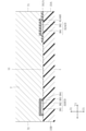
図9は、図4のIX-IX線に沿う断面図である。図10は、図4のX-X線に沿う断面図である。図11は、図4のXI-XI線に沿う断面図である。図12は、図4のXII-XII線に沿う断面図である。図13は、図4のXIII-XIII線に沿う断面図である。 FIG. 9 is a cross-sectional view taken along the line IX-IX of FIG. FIG. 10 is a cross-sectional view taken along the line XX of FIG. FIG. 11 is a cross-sectional view taken along the line XI-XI of FIG. FIG. 12 is a cross-sectional view taken along the line XII-XII of FIG. FIG. 13 is a cross-sectional view taken along the line XIII-XIII of FIG.
導電層3は、例えば、Cu、Ni、Ti、Au、Agなどの単種類または複数種類の金属からなる。図9~図13に示すように、本実施形態においては、導電層3は、箇所381と、箇所382~384と、を含む。箇所382~384は、メッキによって形成されていてもよく、あるいは、スパッタリングやCVD(chemical vapor deposition)により形成されていてもよい。
The
箇所381は、たとえば、Cuよりなる。箇所381は、基板1の主面11および裏面13に直接形成されている。箇所381は、Cuに加え、Cu以外の他の材料を含んでいても良い。
The
箇所382は、たとえばCuよりなる。箇所382は、箇所381に形成されている。本実施形態では特に、箇所382は、箇所381に直接形成されている。本実施形態とは異なり、箇所381が箇所382に直接形成されておらず、箇所381および箇所382の間に他の箇所が介在していてもよい。箇所382は、主面11に形成された箇所381と、裏面13に形成された箇所381とを導通させる。図14に示すように、箇所382は、第1導電部37A、第2導電部37B、第3導電部37C、および第4導電部37Dを構成する。図14は、基板1における貫通孔をレーザにより形成した場合の一例である。図14に示した例とは異なり、基板1における貫通孔をドリルにより形成してもよい。図9、図10等に示すように、箇所382は、導電層3のうち、絶縁層6に覆われた領域、および、絶縁層6から露出している領域のいずれの領域にも形成されている。すなわち、厚さ方向Z1視においては、図4にて示した導電層3の全ての領域に、箇所382が形成されている。
The
箇所383は、たとえばNiよりなる。箇所383は、箇所382に形成されている。本実施形態では特に、箇所383は、箇所382に直接形成されている。本実施形態とは異なり、箇所383が箇所382に直接形成されておらず、箇所383および箇所382の間に他の箇所が介在していてもよい。箇所384は、たとえば、Auよりなる。箇所384は、箇所383に形成されている。本実施形態では特に、箇所384は、箇所383に直接形成されている。本実施形態とは異なり、箇所384が箇所383に直接形成されておらず、箇所384と箇所383との間に他の箇所が介在していてもよい。図9、図10等に示すように、箇所383および箇所384は、導電層3のうち、絶縁層6から露出している領域には形成されているが、絶縁層6に覆われた領域には形成されていない。
The
図5等に示す絶縁層6は、絶縁性を有する材質からなる。絶縁層6は、たとえばレジスト層と称されることがある。絶縁層6は、たとえば樹脂(ポリマー)よりなる。絶縁層6は、半透明な材料あるいは透明でない材料よりなる。絶縁層6は、主面11および導電層3に形成されている。図9、図10等に示すように、絶縁層6は、基板1および封止樹脂部7の間に介在しており、且つ、基板1および封止樹脂部7に接している。
The insulating
図5等に示すように、絶縁層6は、第1絶縁部61Aと、第2絶縁部61Cと、部位63~65と、を含む。
As shown in FIG. 5 and the like, the insulating
第1絶縁部61Aは、第1導電部分32Aに形成されている。第1絶縁部61Aは、第1方向X1において、第2導電箇所31Bと重なる部位を有する。より好ましくは、第1絶縁部61Aは、第1方向X1において、第2接合層52と重なる部位を有する。より好ましくは、第1絶縁部61Aは、第1方向X1において、第2光学素子42に重なる部位を有する。好ましくは、第1絶縁部61Aの縁611A(図5参照)は、第1導電箇所31Aよりも第1方向X1側に位置している。図5に示すように、縁611Aは、第1方向X1において、第2光学素子42と重なる位置に位置していても良い。あるいは、図5の想像線(二点鎖線)で示すように、第1絶縁部61Aの縁は、位置611Bに位置していてもよい。位置611Bは、第2光学素子42よりも第1方向X1側であり、且つ、第1方向X1において、第2接合層52と重なっている。あるいは、図5の想像線(二点鎖線)で示すように、第1絶縁部61Aの縁は、位置611Cに位置していてもよい。位置611Cは、第2接合層52よりも第1方向X1側であり、且つ、第1方向X1において、第2ボンディングパッド31Bと重なっている。
The first insulating
第2絶縁部61Cは、第3導電部分32Cに形成されている。第2絶縁部61Cは、第1方向X1において、第4導電箇所31Dと重なる部位を有する。より好ましくは、第2絶縁部61Cは、第1方向X1において、第1ワイヤ43と重なる部位を有する。第2絶縁部61Cは、第2追加導電部分34Cに形成されている。
The second insulating
部位63は、第1導電部33Aおよび第2導電部33Bに形成されている。部位63は、第1絶縁部61Aにつながっている。部位63は、厚さ方向Z1視において、第1側面15A、第2側面15B、および第3側面15Cに接している。部位64は、第3導電部33Cに形成されている。部位64は、厚さ方向Z1視において、第2側面15Bおよび第4側面15Dに接している。部位64は、第2絶縁部61Cにつながっている。部位65は、第4導電部33Dに形成されている。部位65は、厚さ方向Z1視において、第1側面15Aおよび第4側面15Dに接している。
The
図5等に示す第1光学素子41は、導電層3における第1導電箇所31Aにボンディング(配置)されている。第2光学素子42は、導電層3における第2導電箇所31Bにボンディング(配置)されている。本実施形態では、第1光学素子41および第2光学素子42は各々発光素子あるいは受光素子である。本実施形態では第1光学素子41および第2光学素子42は各々、発光素子であり、光学装置A1の光源となる。本実施形態においては更に、第1光学素子41および第2光学素子42は各々、LEDチップである。本実施形態における第1光学素子41および第2光学素子42は各々、n型半導体層と活性層とp型半導体層とを有する。n型半導体層は活性層に積層されている。活性層はp型半導体層に積層されている。よって、活性層はn型半導体層とp型半導体層との間に位置する。n型半導体層、活性層、および、p型半導体層は、例えば、GaNよりなる。第1光学素子41および第2光学素子42は各々、互いに反対側を向く主面電極パッドおよび裏面電極パッドを有する。なお、これらの主面電極パッドおよび裏面電極パッドの図示は省略する。第1光学素子41および第2光学素子42は各々の発光色は特に限定されない。第1光学素子41および第2光学素子42の発光色が異なっていてもよいし、同一色であってもよい。
The first
図5等に示す第1ワイヤ43は第1光学素子41および第4導電箇所31Dにボンディングされている。第1ワイヤ43は導電性の材料よりなる。第1ワイヤ43は第1光学素子41および第4導電箇所31Dを導通させている。
The
図5等に示す第2ワイヤ44は第2光学素子42および第3導電箇所31Cにボンディングされている。第2ワイヤ44は導電性の材料よりなる。第2ワイヤ44は第2光学素子42および第3導電箇所31Cを導通させている。
The
図5等に示す第1接合層51は第1光学素子41および導電層3(具体的には第1導電箇所31A)の間に介在する。本実施形態では第1接合層51は導電性の材料よりなる。第1接合層51はたとえば銀ペーストに由来する。本実施形態とは異なり第1接合層51は絶縁性の材料よりなっていてもよい。図11に示すように、第1接合層51の一部が第1光学素子41の側面411に這い上がっていてもよく、第1接合層51は、第1光学素子41の側面411に接していてもよい。本実施形態とは異なり、第1接合層51が第1光学素子41の側面に這い上がっていなくてもよい。
The
図5等に示す第2接合層52は第2光学素子42および導電層3(具体的には第2導電箇所31B)の間に介在する。本実施形態では第2接合層52は導電性の材料よりなる。第2接合層52はたとえば銀ペーストに由来する。本実施形態とは異なり第2接合層52は絶縁性の材料よりなっていてもよい。図10に示すように、第2接合層52の一部が第2光学素子42の側面421に這い上がっていてもよく、第2接合層52は、第2光学素子42の側面421に接していてもよい。本実施形態とは異なり、第2接合層52が第2光学素子42の側面に這い上がっていなくてもよい。
The
図9、図10等に示す封止樹脂部7は、基板1、第1光学素子41、第2光学素子42、導電層3、絶縁層6、第1ワイヤ43、および第2ワイヤ44を覆っている。本実施形態では、封止樹脂部7は、光を透過させる樹脂からなる。このような樹脂としては、たとえば、透明あるいは半透明の、エポキシ樹脂、シリコーン樹脂、アクリル樹脂、もしくは、ポリビニル系樹脂などが挙げられる。封止樹脂部7は、第1光学素子41からの光によって励起されることにより異なる波長の光を発する蛍光材料を含むものであってもよい。本実施形態では、樹脂部がいわゆる黒樹脂である場合と異なり、封止樹脂部7にはフィラーが混入していない。
The sealing
封止樹脂部7は、モールド成型により形成される。封止樹脂部7は、方向X1において、基板1よりも小さい。本実施形態においては、封止樹脂部7は、四角錐台状である。封止樹脂部7は、四角錐台状に限らず、基板1の厚さ方向Z1に突き出る半球体状であってもよく、基板1の厚さ方向Z1前方の面を凹面にしてもよい。本実施形態とは異なり、封止樹脂部7および第1光学素子41を包囲するリフレクタが基板1に配置されていてもよい。本実施形態とは異なり、封止樹脂部7の厚さ方向Z1の形状は、基板1の厚さ方向Z1視の形状と同一であってもよい。
The sealing
図12、図13に示すように、封止樹脂部7は、第1外面71および第2外面72を含む。図12に示すように、第1外面71は、第1追加導電部分34Aにおける第1外側面341Aと面一である。図13に示すように、第2外面72は、第2追加導電部分34Cにおける第2外側面341Cと面一である。
As shown in FIGS. 12 and 13, the sealing
次に、本実施形態に係る光学装置A1の製造方法について、図15、図18を参照し、説明する。本実施形態においては、複数の光学装置A1を製造する場合を例に説明する。なお、以下の説明では、上記と同一または類似の構成については上記と同一の符号を付す。 Next, the manufacturing method of the optical device A1 according to the present embodiment will be described with reference to FIGS. 15 and 18. In this embodiment, a case where a plurality of optical devices A1 are manufactured will be described as an example. In the following description, the same or similar configurations as above are designated by the same reference numerals as above.
まず、矩形状の基板100(図15参照)を用意する。基板100は、図1等に示す基板1を複数個形成可能なサイズである。基板100は、上記基板1の材質と同じ材料(すなわちガラスエポキシ樹脂)からなる。次に、基板100に導電層3を形成する。導電層3は、部位34Mを含む。部位34Mは、第1導電箇所31Aおよび第3導電部分32Cとつながっている。部位34Mは、後に、第1追加導電部分34Aおよび第2追加導電部分34Cになる。なお、この時点においては、図9、図10に示した箇所381および箇所382が形成されている。部位34Mは、メッキを形成するための、第1導電箇所31Aおよび第3導電部分32C間の導通経路を確保している。
First, a rectangular substrate 100 (see FIG. 15) is prepared. The
次に、図16に示すように、導電層3が形成された基板100に絶縁層6を形成する。たとえば、基板100にフィルム状のレジストを圧着し貼り付けてもよいし、ペースト状のレジストを塗布してもよい。次に、図示は省略するが、図9、図10等に示した箇所383,384を形成する。
Next, as shown in FIG. 16, the insulating
次に、図17に示すように、第1光学素子41および第2光学素子42を、第1接合層51、第2接合層52をそれぞれ介在させて、導電層3に配置する。次に、第1ワイヤ43を、第1光学素子41と導電層3とにボンディングする。同様に、第2ワイヤ44を、第2光学素子42と導電層3とにボンディングする。
Next, as shown in FIG. 17, the first
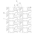
次に、図18に示すように、上述の封止樹脂部7をモード成型により形成した後に、封止樹脂部7が形成された中間品を線Dc1に沿ってダイシングすることにより、図1等に示す光学装置A1が複数個製造される。なお、上記光学装置A1の製造方法において、複数の光学装置A1を製造する場合を例に説明したが、1つずつ製造してもよい。
Next, as shown in FIG. 18, after the above-mentioned
次に、本実施形態の作用効果について説明する。 Next, the action and effect of this embodiment will be described.
本実施形態においては、絶縁層6は、第1導電部分32Aに形成された第1絶縁部61Aを含み、第1絶縁部61Aは、第1方向X1において、第2導電箇所31Bと重なる部位を有する。このような構成によると、導電層3におけるより多くの領域が、絶縁層6に覆われうる。導電層3と封止樹脂部7とは、絶縁層6と封止樹脂部7と比べて、密着しにくい。したがって、本実施形態によると、封止樹脂部7が導電層3から脱離することに伴って、封止樹脂部7に密着している第1光学素子41が、第1導電箇所31Aから脱離することを、防止できる。同様の理由により、第2光学素子42が第2導電箇所31Bから脱離することを、防止できる。
In the present embodiment, the insulating
仮に、縁611Aが第1導電箇所31A上に位置していたならば、封止樹脂部7が絶縁層6と密着する領域が過度に大きくなり、第1光学素子41が第1導電箇所31Aから脱離しにくくなる。その結果、封止樹脂部7のうち、第1光学素子41Aの近傍の部位にクラックが生じるおそれがある。本実施形態では、第1絶縁部61Aにおける縁611Aが、第1導電箇所31Aよりも第1方向X1側に位置している。このような構成によると、上記のクラックが封止樹脂部7に生じることを抑制できる。更に、第1絶縁部61Aの縁が、図5の位置611A,611B,611Cにある場合には、第1光学素子41に応力が集中することを抑制できるので、第1光学素子41が第1導電箇所31Aから脱離しにくくなる効果を享受できる。
If the
本実施形態においては、第1絶縁部61Aは、第1方向X1において、第2接合層52と重なる部位を有する。このような構成によると、導電層3における更に多くの領域が、絶縁層6に覆われうる。その結果、第1光学素子41が、第1導電箇所31Aから脱離することを、抑制できる。同様の理由により、第2光学素子42が第2導電箇所31Bから脱離することを、抑制できる。
In the present embodiment, the first insulating
本実施形態においては、第1絶縁部61Aは、第1方向X1において、第2光学素子42に重なる部位を有する。このような構成によると、導電層3における更に多くの領域が、絶縁層6に覆われうる。その結果、第1光学素子41が、第1導電箇所31Aから脱離することを、抑制できる。同様の理由により、第2光学素子42が第2導電箇所31Bから脱離することを、抑制できる。
In the present embodiment, the first insulating
本実施形態においては、導電層3は、第1導電箇所31Aから延び出る第1追加導電部分34Aを含む。第1追加導電部分34Aは、基板1の厚さ方向Z1視において、第1側面15Aに至っている。このような構成によると、第1光学素子41にて発生した熱を、第1追加導電部分34Aを介して、光学装置A1の外部の放出しやすくなる。これにより、第1光学素子41が過度に高温となることを防止できる。
In the present embodiment, the
本実施形態においては、導電層3は、第3導電箇所31Cあるいは第3導電部分32Cから延び出る第2追加導電部分34Cを含む。第2追加導電部分34Cは、基板1の厚さ方向Z1視において、第2側面15Bに至っている。このような構成によると、第2光学素子42にて発生した熱を、第2ワイヤ44および第2追加導電部分34Cを介して、光学装置A1の外部の放出しやすくなる。これにより、第2光学素子42が過度に高温となることを防止できる。
In the present embodiment, the
本実施形態においては、第1追加導電部分34Aは、基板1の厚さ方向Z1視において、第1方向X1と第2方向Y1とは異なる方向に延びている。このような構成によると、第1追加導電部分34Aをより長くすることができる。これにより、光学装置A1の外部から、第1追加導電部分34Aを伝って湿気が第1導電箇所31Aや第1光学素子41に至ることを、防止できる。
In the present embodiment, the first additional
本実施形態においては、第2追加導電部分34Cは、基板1の厚さ方向Z1視において、第1方向X1と第2方向Y1とは異なる方向に延びている。このような構成によると、第2追加導電部分34Cをより長くすることができる。これにより、光学装置A1の外部から、第2追加導電部分34Cを伝って湿気が第3導電箇所31Cや第2ワイヤ44に至ることを、防止できる。
In the present embodiment, the second additional
図15では、部位34Mが、第3導電箇所31Cにつながっておらず、第3導電部分32Cにつながっている。これにより、光学装置A1の製造の際に、第1導電箇所31Aに配置されるペースト(後に第1接合層51となる)が、部位34Mを伝って第3導電箇所31Cに至ることを防止できる。その結果、第2ワイヤ44を適切に、第3導電箇所31Cにボンディングできる。
In FIG. 15, the
図17では、絶縁層6の縁69が部位34M上に位置している。これにより、光学装置A1の製造の際に、上記ペーストが部位34Mを伝ってきたとしても、縁69において、上記ペーストをせき止めることができる。
In FIG. 17, the
本発明は、上述した実施形態に限定されるものではない。本発明の各部の具体的な構成は、種々に設計変更自在である。 The present invention is not limited to the above-described embodiment. The specific configuration of each part of the present invention can be freely redesigned.
上記実施形態は、以下の付記を含む。
[付記1]
基板と、
前記基板に形成された導電層と、
前記導電層に形成された絶縁層と、
前記導電層に配置された第1光学素子と、
前記第1光学素子を覆う封止樹脂部と、を備え、
前記導電層は、第1導電箇所と、前記第1導電箇所から離間した第2導電箇所と、前記第1導電箇所から第1方向に延び出る第1導電部分と、を含み、
前記第1導電部分は、前記第2導電箇所から、前記第1方向に交差する第2方向に対し離間しており、
前記絶縁層は、前記第1導電部分に形成された第1絶縁部を含み、前記第1絶縁部は、前記第1方向において、前記第2導電箇所と重なる部位を有する、光学装置。
[付記2]
前記導電層に配置された第2光学素子を更に備え、
前記第1光学素子は、前記第1導電箇所に配置されており、
前記第2光学素子は、前記第2導電箇所に配置されている、付記1に記載の光学装置。
[付記3]
前記第1光学素子および前記第1導電箇所の間に介在する第1接合層と、
前記第2光学素子および前記第2導電箇所の間に介在する第2接合層と、を更に備え、
前記第1絶縁部は、前記第1方向において、前記第2接合層と重なる部位を有する、付記2に記載の光学装置。
[付記4]
前記第1絶縁部は、前記第1方向において、前記第2光学素子に重なる部位を有する、付記3に記載の光学装置。
[付記5]
前記基板は、前記第2方向に互いに離間する第1側面および第2側面を含み、前記第1側面および前記第2側面は、互いに反対側を向いており、
前記導電層は、前記第1導電箇所から延び出る第1追加導電部分を含み、
前記第1追加導電部分は、前記基板の厚さ方向視において、前記第1側面に至っている、付記2ないし付記4のいずれかに記載の光学装置。
[付記6]
前記第1追加導電部分は、前記基板の厚さ方向視において、前記第1方向と前記第2方向とは異なる方向に延びている、付記5に記載の光学装置。
[付記7]
前記第1追加導電部分は、前記絶縁層から露出している、付記5または付記6に記載の光学装置。
[付記8]
前記第1追加導電部分は、前記第1側面と面一である第1外側面を有する、付記5ないし付記7のいずれかに記載の光学装置。
[付記9]
前記導電層は、前記第2導電箇所から延び出る第2導電部分を含む、付記5に記載の光学装置。
[付記10]
前記導電層は、前記第1導電箇所および前記第2導電箇所から離間する第3導電箇所と、前記第3導電箇所から前記第2導電箇所とは反対側に延び出る第3導電部分と、を含み、
前記絶縁層は、前記第3導電部分に形成された第2絶縁部を含む、付記9に記載の光学装置。
[付記11]
前記導電層は、前記第3導電箇所あるいは前記第3導電部分から延び出る第2追加導電部分を含み、
前記第2追加導電部分は、前記基板の厚さ方向視において、前記第2側面に至っている、付記10に記載の光学装置。
[付記12]
前記第2追加導電部分は、前記基板の厚さ方向視において、前記第1導電部分が延びる方向と同一方向に延びている、付記11に記載の光学装置。
[付記13]
前記第2追加導電部分は、前記絶縁層から露出している、付記11または付記12に記載の光学装置。
[付記14]
前記第2追加導電部分は、前記第2側面と面一である第2外側面を有し、
前記第2追加導電部分の前記第2外側面および前記第1追加導電部分の前記第1外側面はいずれも、前記第2方向に沿って延びる仮想線であって、前記厚さ方向視における前記基板の中心を通る仮想線に対し、前記厚さ方向視において同一側に位置している、付記11ないし付記13のいずれかに記載の光学装置。
[付記15]
前記絶縁層は、前記第2追加導電部分に形成されている、付記11ないし付記14のいずれかに記載の光学装置。
[付記16]
前記第1光学素子にボンディングされた第1ワイヤと、
前記第2光学素子にボンディングされた第2ワイヤと、を更に備える、付記2ないし付記15のいずれかに記載の光学装置。
The above embodiment includes the following appendices.
[Appendix 1]
With the board
The conductive layer formed on the substrate and
The insulating layer formed on the conductive layer and
The first optical element arranged on the conductive layer and
A sealing resin portion that covers the first optical element is provided.
The conductive layer includes a first conductive portion, a second conductive portion separated from the first conductive portion, and a first conductive portion extending in a first direction from the first conductive portion.
The first conductive portion is separated from the second conductive portion with respect to the second direction intersecting with the first direction.
The insulating layer includes a first insulating portion formed in the first conductive portion, and the first insulating portion has a portion that overlaps with the second conductive portion in the first direction.
[Appendix 2]
A second optical element arranged on the conductive layer is further provided.
The first optical element is arranged at the first conductive portion, and the first optical element is arranged at the first conductive portion.
The optical device according to
[Appendix 3]
A first bonding layer interposed between the first optical element and the first conductive portion,
A second bonding layer interposed between the second optical element and the second conductive portion is further provided.
The optical device according to Appendix 2, wherein the first insulating portion has a portion overlapping the second bonding layer in the first direction.
[Appendix 4]
The optical device according to
[Appendix 5]
The substrate includes a first side surface and a second side surface that are separated from each other in the second direction, and the first side surface and the second side surface face opposite to each other.
The conductive layer includes a first additional conductive portion extending from the first conductive portion.
The optical device according to any one of Supplementary note 2 to Supplementary note 4, wherein the first additional conductive portion reaches the first side surface in the thickness direction of the substrate.
[Appendix 6]
The optical device according to Appendix 5, wherein the first additional conductive portion extends in a direction different from the first direction and the second direction in the thickness direction of the substrate.
[Appendix 7]
The optical device according to
[Appendix 8]
The optical device according to any one of Supplementary note 5 to
[Appendix 9]
The optical device according to Appendix 5, wherein the conductive layer includes a second conductive portion extending from the second conductive portion.
[Appendix 10]
The conductive layer comprises a first conductive portion, a third conductive portion separated from the second conductive portion, and a third conductive portion extending from the third conductive portion to a side opposite to the second conductive portion. Including,
The optical device according to Appendix 9, wherein the insulating layer includes a second insulating portion formed in the third conductive portion.
[Appendix 11]
The conductive layer includes a second additional conductive portion extending from the third conductive portion or the third conductive portion.
The optical device according to Appendix 10, wherein the second additional conductive portion reaches the second side surface in the thickness direction of the substrate.
[Appendix 12]
The optical device according to
[Appendix 13]
The optical device according to
[Appendix 14]
The second additional conductive portion has a second outer surface that is flush with the second side surface.
Both the second outer surface of the second additional conductive portion and the first outer surface of the first additional conductive portion are virtual lines extending along the second direction, and are the above-mentioned in the thickness direction view. The optical device according to any one of
[Appendix 15]
The optical device according to any one of
[Appendix 16]
The first wire bonded to the first optical element and
The optical device according to any one of Supplementary Provisions 2 to 15, further comprising a second wire bonded to the second optical element.
1 基板
11 主面
13 裏面
15A 第1側面
15B 第2側面
15C 第3側面
15D 第4側面
3 導電層
31A 第1導電箇所
31B 第2導電箇所
31C 第3導電箇所
31D 第4導電箇所
32A 第1導電部分
32B 第2導電部分
32C 第3導電部分
32D 第4導電部分
33A 第1導電部
33B 第2導電部
33C 第3導電部
33D 第4導電部
341A 第1外側面
341C 第2外側面
34A 第1追加導電部分
34C 第2追加導電部分
34M 部位
37A 第1導電部
37B 第2導電部
37C 第3導電部
37D 第4導電部
381 箇所
382 箇所
383 箇所
384 箇所
38A 第1裏面部
38B 第2裏面部
38C 第3裏面部
38D 第4裏面部
41 第1光学素子
42 第2光学素子
43 第1ワイヤ
44 第2ワイヤ
51 第1接合層
52 第2接合層
6 絶縁層
611A 縁
61A 第1絶縁部
61C 第2絶縁部
63 部位
64 部位
65 部位
69 縁
7 封止樹脂部
71 第1外面
72 第2外面
81 絶縁層
A1 光学装置
C1 中心
L1 仮想線
X1 第1方向
Y1 第2方向
Z1 厚さ方向
1
Claims (14)
前記基板に形成された導電層と、
前記導電層に形成された絶縁層と、
前記導電層に配置された第1光学素子と、
前記第1光学素子を覆う封止樹脂部と、を備え、
前記導電層は、第1導電箇所と、前記第1導電箇所から離間した第2導電箇所と、前記第1導電箇所から第1方向に延び出る第1導電部分と、を含み、
前記第1導電部分は、前記第2導電箇所から、前記第1方向に交差する第2方向に対し離間しており、
前記絶縁層は、前記第1導電部分に形成された第1絶縁部を含み、前記第1絶縁部は、前記第2方向に沿って見て、前記第2導電箇所と重なる部位を有し、
前記導電層に配置された第2光学素子を更に備え、
前記第1光学素子は、前記第1導電箇所に配置されており、
前記第2光学素子は、前記第2導電箇所に配置されており、
前記基板は、前記第2方向に互いに離間する第1側面および第2側面を含み、前記第1側面および前記第2側面は、互いに反対側を向いており、
前記導電層は、前記第1導電箇所から延び出る第1追加導電部分を含み、
前記第1追加導電部分は、前記基板の厚さ方向視において、前記第1側面に至っている、
光学装置。 With the board
The conductive layer formed on the substrate and
The insulating layer formed on the conductive layer and
The first optical element arranged on the conductive layer and
A sealing resin portion that covers the first optical element is provided.
The conductive layer includes a first conductive portion, a second conductive portion separated from the first conductive portion, and a first conductive portion extending in a first direction from the first conductive portion.
The first conductive portion is separated from the second conductive portion with respect to the second direction intersecting with the first direction.
The insulating layer includes a first insulating portion formed in the first conductive portion, and the first insulating portion has a portion overlapping the second conductive portion when viewed along the second direction.
A second optical element arranged on the conductive layer is further provided.
The first optical element is arranged at the first conductive portion, and the first optical element is arranged at the first conductive portion.
The second optical element is arranged at the second conductive portion.
The substrate includes a first side surface and a second side surface that are separated from each other in the second direction, and the first side surface and the second side surface face opposite to each other.
The conductive layer includes a first additional conductive portion extending from the first conductive portion.
The first additional conductive portion reaches the first side surface in the thickness direction of the substrate.
Optical equipment.
前記第2光学素子および前記第2導電箇所の間に介在する第2接合層と、を更に備え、
前記第1絶縁部は、前記第2方向に沿って見て、前記第2接合層と重なる部位を有する、請求項1に記載の光学装置。 A first bonding layer interposed between the first optical element and the first conductive portion,
A second bonding layer interposed between the second optical element and the second conductive portion is further provided.
The optical device according to claim 1 , wherein the first insulating portion has a portion overlapping the second bonding layer when viewed along the second direction.
前記絶縁層は、前記第3導電部分に形成された第2絶縁部を含む、請求項7に記載の光学装置。 The conductive layer comprises a first conductive portion, a third conductive portion separated from the second conductive portion, and a third conductive portion extending from the third conductive portion to a side opposite to the second conductive portion. Including,
The optical device according to claim 7 , wherein the insulating layer includes a second insulating portion formed in the third conductive portion.
前記第2追加導電部分は、前記基板の厚さ方向視において、前記第2側面に至っている、請求項8に記載の光学装置。 The conductive layer includes a second additional conductive portion extending from the third conductive portion or the third conductive portion.
The optical device according to claim 8 , wherein the second additional conductive portion reaches the second side surface in the thickness direction of the substrate.
前記第2追加導電部分の前記第2外側面および前記第1追加導電部分の前記第1外側面はいずれも、前記第2方向に沿って延びる仮想線であって、前記厚さ方向視における前記基板の中心を通る仮想線に対し、前記厚さ方向視において同一側に位置している、請求項9ないし請求項11のいずれかに記載の光学装置。 The second additional conductive portion has a second outer surface that is flush with the second side surface.
Both the second outer surface of the second additional conductive portion and the first outer surface of the first additional conductive portion are virtual lines extending along the second direction, and are the above-mentioned in the thickness direction view. The optical device according to any one of claims 9 to 11 , which is located on the same side in the thickness direction with respect to the virtual line passing through the center of the substrate.
前記第2光学素子にボンディングされた第2ワイヤと、を更に備える、請求項1ないし請求項13のいずれかに記載の光学装置。 The first wire bonded to the first optical element and
The optical device according to claim 1 , further comprising a second wire bonded to the second optical element.
Priority Applications (2)
| Application Number | Priority Date | Filing Date | Title |
|---|---|---|---|
| JP2017114141A JP7004397B2 (en) | 2017-06-09 | 2017-06-09 | Optical equipment |
| US16/002,219 US10439117B2 (en) | 2017-06-09 | 2018-06-07 | Optical device |
Applications Claiming Priority (1)
| Application Number | Priority Date | Filing Date | Title |
|---|---|---|---|
| JP2017114141A JP7004397B2 (en) | 2017-06-09 | 2017-06-09 | Optical equipment |
Publications (2)
| Publication Number | Publication Date |
|---|---|
| JP2018207063A JP2018207063A (en) | 2018-12-27 |
| JP7004397B2 true JP7004397B2 (en) | 2022-01-21 |
Family
ID=64563671
Family Applications (1)
| Application Number | Title | Priority Date | Filing Date |
|---|---|---|---|
| JP2017114141A Active JP7004397B2 (en) | 2017-06-09 | 2017-06-09 | Optical equipment |
Country Status (2)
| Country | Link |
|---|---|
| US (1) | US10439117B2 (en) |
| JP (1) | JP7004397B2 (en) |
Citations (14)
| Publication number | Priority date | Publication date | Assignee | Title |
|---|---|---|---|---|
| JP2000183406A (en) | 1998-12-15 | 2000-06-30 | Matsushita Electric Works Ltd | Light emitting diode |
| JP2002314143A (en) | 2001-04-09 | 2002-10-25 | Toshiba Corp | Light emitting device |
| JP2003264267A (en) | 2002-03-08 | 2003-09-19 | Rohm Co Ltd | Semiconductor device using semiconductor chip |
| JP2005538550A (en) | 2002-09-04 | 2005-12-15 | クリー インコーポレイテッド | Power surface mounted light emitting die package |
| JP2008288228A (en) | 2007-05-15 | 2008-11-27 | Sony Corp | Light emitting device, light source device, and liquid crystal display device |
| WO2009011302A1 (en) | 2007-07-13 | 2009-01-22 | Rohm Co., Ltd. | Led module and led dot matrix display |
| JP2009105198A (en) | 2007-10-23 | 2009-05-14 | Sanyo Electric Co Ltd | Printed wiring board and light emitting device having the same |
| JP2011003798A (en) | 2009-06-19 | 2011-01-06 | Japan Aviation Electronics Industry Ltd | Electric connection member and socket connector using the same |
| US20110156090A1 (en) | 2008-03-25 | 2011-06-30 | Lin Charles W C | Semiconductor chip assembly with post/base/post heat spreader and asymmetric posts |
| JP2012517709A (en) | 2009-02-12 | 2012-08-02 | オスラム オプト セミコンダクターズ ゲゼルシャフト ミット ベシュレンクテル ハフツング | Semiconductor structure and method for manufacturing semiconductor structure |
| JP2012186450A (en) | 2011-02-16 | 2012-09-27 | Rohm Co Ltd | Led module |
| JP2014160756A (en) | 2013-02-20 | 2014-09-04 | Stanley Electric Co Ltd | Light emitting element module |
| JP2015115432A (en) | 2013-12-11 | 2015-06-22 | ローム株式会社 | Semiconductor device |
| JP2015201605A (en) | 2014-04-10 | 2015-11-12 | 日亜化学工業株式会社 | Light emitting device and method for manufacturing light emitting device |
Family Cites Families (2)
| Publication number | Priority date | Publication date | Assignee | Title |
|---|---|---|---|---|
| JP2002314138A (en) * | 2001-04-09 | 2002-10-25 | Toshiba Corp | Light emitting device |
| KR101380390B1 (en) * | 2013-06-28 | 2014-04-02 | 서울반도체 주식회사 | Anti moisture led package |
-
2017
- 2017-06-09 JP JP2017114141A patent/JP7004397B2/en active Active
-
2018
- 2018-06-07 US US16/002,219 patent/US10439117B2/en active Active
Patent Citations (14)
| Publication number | Priority date | Publication date | Assignee | Title |
|---|---|---|---|---|
| JP2000183406A (en) | 1998-12-15 | 2000-06-30 | Matsushita Electric Works Ltd | Light emitting diode |
| JP2002314143A (en) | 2001-04-09 | 2002-10-25 | Toshiba Corp | Light emitting device |
| JP2003264267A (en) | 2002-03-08 | 2003-09-19 | Rohm Co Ltd | Semiconductor device using semiconductor chip |
| JP2005538550A (en) | 2002-09-04 | 2005-12-15 | クリー インコーポレイテッド | Power surface mounted light emitting die package |
| JP2008288228A (en) | 2007-05-15 | 2008-11-27 | Sony Corp | Light emitting device, light source device, and liquid crystal display device |
| WO2009011302A1 (en) | 2007-07-13 | 2009-01-22 | Rohm Co., Ltd. | Led module and led dot matrix display |
| JP2009105198A (en) | 2007-10-23 | 2009-05-14 | Sanyo Electric Co Ltd | Printed wiring board and light emitting device having the same |
| US20110156090A1 (en) | 2008-03-25 | 2011-06-30 | Lin Charles W C | Semiconductor chip assembly with post/base/post heat spreader and asymmetric posts |
| JP2012517709A (en) | 2009-02-12 | 2012-08-02 | オスラム オプト セミコンダクターズ ゲゼルシャフト ミット ベシュレンクテル ハフツング | Semiconductor structure and method for manufacturing semiconductor structure |
| JP2011003798A (en) | 2009-06-19 | 2011-01-06 | Japan Aviation Electronics Industry Ltd | Electric connection member and socket connector using the same |
| JP2012186450A (en) | 2011-02-16 | 2012-09-27 | Rohm Co Ltd | Led module |
| JP2014160756A (en) | 2013-02-20 | 2014-09-04 | Stanley Electric Co Ltd | Light emitting element module |
| JP2015115432A (en) | 2013-12-11 | 2015-06-22 | ローム株式会社 | Semiconductor device |
| JP2015201605A (en) | 2014-04-10 | 2015-11-12 | 日亜化学工業株式会社 | Light emitting device and method for manufacturing light emitting device |
Also Published As
| Publication number | Publication date |
|---|---|
| US20180358524A1 (en) | 2018-12-13 |
| JP2018207063A (en) | 2018-12-27 |
| US10439117B2 (en) | 2019-10-08 |
Similar Documents
| Publication | Publication Date | Title |
|---|---|---|
| CN102683509B (en) | Led module | |
| CN101459166B (en) | Licht aussendende diode | |
| JP6293995B2 (en) | Light emitting element mounting package, method for manufacturing the same, and light emitting element package | |
| JP6483800B2 (en) | Light emitting element mounting package, light emitting device, and light emitting module | |
| JP6855787B2 (en) | Light emitting element | |
| JP7283938B2 (en) | semiconductor light emitting device | |
| JP2013161903A (en) | Semiconductor device and method of manufacturing the same | |
| US9537019B2 (en) | Semiconductor device | |
| TWI455363B (en) | Light-emitting diode package structure and manufacturing method thereof | |
| KR20130051206A (en) | Light emitting module | |
| JP4863193B2 (en) | Semiconductor light emitting device | |
| JP5745784B2 (en) | Light emitting diode | |
| JP2022180523A (en) | semiconductor equipment | |
| JP4831958B2 (en) | Surface mount type LED | |
| JP7004397B2 (en) | Optical equipment | |
| JP2005353802A (en) | Light emitting diode | |
| JP5912471B2 (en) | Semiconductor device | |
| JP5809965B2 (en) | Semiconductor light emitting device | |
| JP6543391B2 (en) | Semiconductor device | |
| WO2010140693A1 (en) | Electronic component | |
| JP6679799B2 (en) | Light emitting device | |
| TW201427116A (en) | LED package with tilted structure | |
| JP2014022705A (en) | Semiconductor light-emitting device and manufacturing method of the same | |
| JP2016032082A (en) | Peeling prevention method for plating film, component assembly and light-emitting device | |
| JP2019110292A (en) | Semiconductor light-emitting device |
Legal Events
| Date | Code | Title | Description |
|---|---|---|---|
| A621 | Written request for application examination |
Free format text: JAPANESE INTERMEDIATE CODE: A621 Effective date: 20200511 |
|
| A977 | Report on retrieval |
Free format text: JAPANESE INTERMEDIATE CODE: A971007 Effective date: 20210430 |
|
| A131 | Notification of reasons for refusal |
Free format text: JAPANESE INTERMEDIATE CODE: A131 Effective date: 20210511 |
|
| A521 | Request for written amendment filed |
Free format text: JAPANESE INTERMEDIATE CODE: A523 Effective date: 20210614 |
|
| TRDD | Decision of grant or rejection written | ||
| A01 | Written decision to grant a patent or to grant a registration (utility model) |
Free format text: JAPANESE INTERMEDIATE CODE: A01 Effective date: 20211130 |
|
| A61 | First payment of annual fees (during grant procedure) |
Free format text: JAPANESE INTERMEDIATE CODE: A61 Effective date: 20211224 |
|
| R150 | Certificate of patent or registration of utility model |
Ref document number: 7004397 Country of ref document: JP Free format text: JAPANESE INTERMEDIATE CODE: R150 |
|
| R250 | Receipt of annual fees |
Free format text: JAPANESE INTERMEDIATE CODE: R250 |
|
| R250 | Receipt of annual fees |
Free format text: JAPANESE INTERMEDIATE CODE: R250 |