JP7002314B2 - Pneumatic tires - Google Patents
Pneumatic tires Download PDFInfo
- Publication number
- JP7002314B2 JP7002314B2 JP2017238967A JP2017238967A JP7002314B2 JP 7002314 B2 JP7002314 B2 JP 7002314B2 JP 2017238967 A JP2017238967 A JP 2017238967A JP 2017238967 A JP2017238967 A JP 2017238967A JP 7002314 B2 JP7002314 B2 JP 7002314B2
- Authority
- JP
- Japan
- Prior art keywords
- rubber
- tire
- conductive
- belt
- radial direction
- Prior art date
- Legal status (The legal status is an assumption and is not a legal conclusion. Google has not performed a legal analysis and makes no representation as to the accuracy of the status listed.)
- Active
Links
Images


Classifications
-
- B—PERFORMING OPERATIONS; TRANSPORTING
- B60—VEHICLES IN GENERAL
- B60C—VEHICLE TYRES; TYRE INFLATION; TYRE CHANGING; CONNECTING VALVES TO INFLATABLE ELASTIC BODIES IN GENERAL; DEVICES OR ARRANGEMENTS RELATED TO TYRES
- B60C19/00—Tyre parts or constructions not otherwise provided for
- B60C19/08—Electric-charge-dissipating arrangements
- B60C19/084—Electric-charge-dissipating arrangements using conductive carcasses
-
- B—PERFORMING OPERATIONS; TRANSPORTING
- B60—VEHICLES IN GENERAL
- B60C—VEHICLE TYRES; TYRE INFLATION; TYRE CHANGING; CONNECTING VALVES TO INFLATABLE ELASTIC BODIES IN GENERAL; DEVICES OR ARRANGEMENTS RELATED TO TYRES
- B60C19/00—Tyre parts or constructions not otherwise provided for
- B60C19/08—Electric-charge-dissipating arrangements
-
- B—PERFORMING OPERATIONS; TRANSPORTING
- B60—VEHICLES IN GENERAL
- B60C—VEHICLE TYRES; TYRE INFLATION; TYRE CHANGING; CONNECTING VALVES TO INFLATABLE ELASTIC BODIES IN GENERAL; DEVICES OR ARRANGEMENTS RELATED TO TYRES
- B60C15/00—Tyre beads, e.g. ply turn-up or overlap
- B60C15/06—Flipper strips, fillers, or chafing strips and reinforcing layers for the construction of the bead
- B60C2015/0617—Flipper strips, fillers, or chafing strips and reinforcing layers for the construction of the bead comprising a cushion rubber other than the chafer or clinch rubber
-
- Y—GENERAL TAGGING OF NEW TECHNOLOGICAL DEVELOPMENTS; GENERAL TAGGING OF CROSS-SECTIONAL TECHNOLOGIES SPANNING OVER SEVERAL SECTIONS OF THE IPC; TECHNICAL SUBJECTS COVERED BY FORMER USPC CROSS-REFERENCE ART COLLECTIONS [XRACs] AND DIGESTS
- Y02—TECHNOLOGIES OR APPLICATIONS FOR MITIGATION OR ADAPTATION AGAINST CLIMATE CHANGE
- Y02T—CLIMATE CHANGE MITIGATION TECHNOLOGIES RELATED TO TRANSPORTATION
- Y02T10/00—Road transport of goods or passengers
- Y02T10/80—Technologies aiming to reduce greenhouse gasses emissions common to all road transportation technologies
- Y02T10/86—Optimisation of rolling resistance, e.g. weight reduction
Description
本発明は空気入りタイヤ(以下、単に「タイヤ」とも称する)に関し、詳しくは、導電性を改良した乗用車用空気入りタイヤ、特には空気入りラジアルタイヤに関する。 The present invention relates to a pneumatic tire (hereinafter, also simply referred to as a "tire"), and more particularly to a passenger vehicle pneumatic tire having improved conductivity, particularly a pneumatic radial tire.
近年、タイヤの低燃費性への要求の高まりに伴い、タイヤに低ロスのゴム組成物を適用して、タイヤの転がり抵抗を低下させる試みがなされている。タイヤの転がり抵抗を低下させる観点からは、低ロスのトレッドゴムに加えて、タイヤを構成する各種ケース部材についても、低ロスのゴム組成物を適用することが有利である。 In recent years, with the increasing demand for low fuel consumption of tires, attempts have been made to apply a low-loss rubber composition to the tire to reduce the rolling resistance of the tire. From the viewpoint of reducing the rolling resistance of the tire, it is advantageous to apply the low-loss rubber composition not only to the low-loss tread rubber but also to various case members constituting the tire.
一方で、従来、車両本体から発生する電気を外部に逃がす手段として、タイヤを介して地面に逃がす方法が一般にとられている。しかし、タイヤに使用するゴム組成物の低ロス化を進めると、タイヤの電気抵抗が上昇して、電気が十分逃がせず、ラジオノイズや、車両のドアを開閉する際の静電気発生等につながってしまう。タイヤの一部部材を高ロス部材にすることでタイヤ電気抵抗を低下させることはできるが、タイヤの転がり抵抗が悪化するなどの問題が生ずる。 On the other hand, conventionally, as a means for releasing electricity generated from a vehicle body to the outside, a method of releasing electricity to the ground via a tire is generally adopted. However, if the loss of the rubber composition used for the tire is reduced, the electric resistance of the tire will increase and the electricity will not escape sufficiently, leading to radio noise and static electricity generation when opening and closing the vehicle door. It ends up. Although it is possible to reduce the electric resistance of a tire by making a part of the tire a high loss member, there are problems such as deterioration of the rolling resistance of the tire.
これに対し、従来、タイヤ内に導電性部材を配置することによりタイヤの電気抵抗を下げる試みが種々なされてきている。例えば、特許文献1には、少なくともビード部からベルト層まで連続して延在する導電部を備え、導電部が線状構造を有すると共に、この線状構造が、所定の電気抵抗率をもつ導電物質を線状に成形して成る導電線状体を含んで構成されるタイヤが開示されている。
On the other hand, conventionally, various attempts have been made to reduce the electric resistance of the tire by arranging the conductive member in the tire. For example,
しかしながら、特許文献1におけるように導電性繊維を配置するのみでは、一部の導電パスしか確保できないため、タイヤのケース部材のさらなる低ロス化を図りつつタイヤ全体の電気抵抗を下げるためには、十分なものではなかった。
However, since only a part of the conductive paths can be secured only by arranging the conductive fibers as in
そこで本発明の目的は、上記問題を解消して、タイヤのケース部材のさらなる低ロス化により転がり抵抗のさらなる低減を図った場合でも、タイヤ全体の電気抵抗を低下させることができる空気入りタイヤを提供することにある。 Therefore, an object of the present invention is to provide a pneumatic tire capable of reducing the electric resistance of the entire tire even when the above problem is solved and the rolling resistance is further reduced by further reducing the loss of the tire case member. To provide.
本発明者は鋭意検討した結果、下記構成とすることにより、上記課題を解決できることを見出して、本発明を完成するに至った。 As a result of diligent studies, the present inventor has found that the above problems can be solved by adopting the following configuration, and has completed the present invention.
すなわち、本発明は、一対のビード部間に跨ってトロイド状に延在する少なくとも1枚のカーカスプライからなるカーカスを骨格とし、該カーカスのクラウン部タイヤ半径方向外側に配置されたトレッドゴムと、該トレッドゴムをタイヤ表面の接地領域からタイヤ半径方向内側に向かって貫通して設けられる導電性ゴム部と、該ビード部のタイヤ幅方向外表面に配置されたゴムチェーファーと、を備える空気入りタイヤにおいて、
前記カーカスと前記トレッドゴムとの間に少なくとも1枚のベルト層が配置され、該ベルト層のタイヤ幅方向端部であって該ベルト層と該カーカスとの間にベルト端クッションゴムが配置され、該ベルト層のタイヤ半径方向外側にキャップ層が設けられ、前記導電性ゴム部が、該キャップ層を貫通して該ベルト層に接しており、
前記導電性ゴム部のタイヤ半径方向内側端部から前記ゴムチェーファーまでを電気的に接続する導電性部材が配置され、該導電性部材が、導電性繊維および前記ベルト端クッションゴムからなるとともに、少なくとも該導電性ゴム部のタイヤ半径方向内側端部近傍および該ゴムチェーファー近傍における該導電性部材が該導電性繊維からなり、該導電性繊維が、タイヤ全体で少なくとも2本以上設けられており、かつ、該導電性部材の体積抵抗率が1×10⁸Ω・cm以下であることを特徴とするものである。
That is, the present invention has a tread rubber having a carcass composed of at least one carcass ply extending in a tread shape straddling between a pair of bead portions as a skeleton, and a tread rubber arranged on the outer side of the crown portion in the tire radial direction of the carcass. Pneumatic including a conductive rubber portion provided so as to penetrate the tread rubber from the ground contact region of the tire surface toward the inside in the tire radial direction, and a rubber chafer arranged on the outer surface of the bead portion in the tire width direction. In tires
At least one belt layer is arranged between the carcass and the tread rubber, and a belt end cushion rubber is arranged at the end of the belt layer in the tire width direction between the belt layer and the carcass. A cap layer is provided on the outer side of the belt layer in the tire radial direction, and the conductive rubber portion penetrates the cap layer and is in contact with the belt layer.
A conductive member that electrically connects the inner end portion of the conductive rubber portion in the radial direction of the tire to the rubber chafer is arranged, and the conductive member is composed of a conductive fiber and the belt end cushion rubber, and also At least the conductive member in the vicinity of the inner end portion in the radial direction of the tire and the vicinity of the rubber chafer of the conductive rubber portion is made of the conductive fiber, and at least two or more of the conductive fibers are provided in the entire tire. Moreover, the volume resistance of the conductive member is 1 × 10⁸ Ω · cm or less.
本発明においては、前記導電性ゴム部のタイヤ半径方向内側端部から前記ベルト端クッションゴムまで、および、該ベルト端クッションゴムから前記ゴムチェーファーまでの領域に、前記導電性繊維が配置されていることが好ましい。また、本発明においては、前記ベルト層と前記キャップ層との間に、前記導電性繊維が配置されているものとすることができる。 In the present invention, the conductive fibers are arranged in the region from the inner end portion of the conductive rubber portion in the tire radial direction to the belt end cushion rubber, and from the belt end cushion rubber to the rubber chafer. It is preferable to have. Further, in the present invention, the conductive fibers may be arranged between the belt layer and the cap layer.
さらに、本発明において、前記ゴムチェーファーの体積抵抗率は、好適には1×10¹⁰Ω・cm以下であり、前記ベルト層のコーティングゴムの体積抵抗率は、好適には1×10⁸Ω・cm以上であり、前記カーカスのコーティングゴムの体積抵抗率は、好適には1×10⁸Ω・cm以上である。 Further, in the present invention, the volume resistivity of the rubber chafer is preferably 1 × 10 10 Ω · cm or less, and the volume resistivity of the coated rubber of the belt layer is preferably 1 × 10 8 Ω. -Cm or more, and the volume resistivity of the coating rubber of the carcas is preferably 1 × 10⁸ Ω · cm or more.
本発明によれば、タイヤのケース部材のさらなる低ロス化により転がり抵抗のさらなる低減を図った場合でも、タイヤ全体の電気抵抗を低下させることができる空気入りタイヤを実現できた。 According to the present invention, it is possible to realize a pneumatic tire capable of reducing the electric resistance of the entire tire even when the rolling resistance is further reduced by further reducing the loss of the tire case member.
以下、本発明の実施の形態について、図面を参照しつつ詳細に説明する。 Hereinafter, embodiments of the present invention will be described in detail with reference to the drawings.
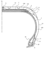
図1に、本発明の空気入りタイヤの一例を示す幅方向片側断面図を示す。図示する空気入りタイヤは、一対のビード部11と、一対のビード部11からそれぞれタイヤ半径方向外側に連なる一対のサイドウォール部12と、一対のサイドウォール部12間に跨って延びて接地部を形成するトレッド部13とを備える。また、図示するタイヤは、一対のビード部11間に跨ってトロイド状に延在する少なくとも1枚、例えば1~3枚、図示する例では1枚のカーカスプライからなるカーカス1を骨格とし、そのクラウン部タイヤ半径方向外側に配置された少なくとも1枚、例えば2~4枚、図示する例では2枚のベルト層2を備えている。さらに、ビード部11のタイヤ幅方向外表面には、ゴムチェーファー3が配設されている。さらにまた、ベルト層2のタイヤ半径方向外側には、クッションゴム13C、および、踏面部を形成するトレッドゴム13Gが順次配設されており、ベルト層2のタイヤ幅方向端部であってベルト層2とカーカス1との間には、ベルト端クッションゴム4が配置されている。さらにまた、図示するタイヤにおいては、トレッドゴム13Gをタイヤ表面の接地領域からタイヤ半径方向内側に向かって貫通する、導電性ゴム部5が配置されている。符号CLは、タイヤ赤道線を意味する。
FIG. 1 shows a cross-sectional view on one side in the width direction showing an example of the pneumatic tire of the present invention. The illustrated tire has a pair of
本発明のタイヤにおいては、導電性ゴム部5のタイヤ半径方向内側端部からゴムチェーファー3までを電気的に接続する、体積抵抗率が1×10⁸Ω・cm以下の導電性部材6が配置されており、少なくとも導電性ゴム部5のタイヤ半径方向内側端部近傍およびゴムチェーファー3の近傍における導電性部材6が、導電性繊維7からなる点に特徴がある。少なくとも一部に導電性繊維7を用いた導電性部材6を、導電性ゴム部5のタイヤ半径方向内側端部からゴムチェーファー3までを導通可能に配置することで、路面に接する導電性ゴム部5からリム20に接するゴムチェーファー3までの、タイヤ内における導電パスを確実に確保することができる。これにより、従来導電パスとして使用されていたベルト層2などのケース部材に使用されるゴム組成物を低ロス化して転がり抵抗の低減を図っても、導電パスが確保されるので、低燃費性を確保しつつ、タイヤ全体の電気抵抗を低下させることができる。ここで、ケース部材としては、ベルト層2の他に、例えば、カーカス1、ゴムチェーファー3、ベルト端クッションゴム4、サイドゴム12G、ベルト層2のタイヤ半径方向外側にベルト層2を覆う幅で配置されるキャップ層およびレイヤー層(図示せず)などが挙げられる。
In the tire of the present invention, the
本発明に係る導電性部材6としては、導電性ゴム部5からゴムチェーファー3までを導通可能なものであって、少なくとも導電性ゴム部5のタイヤ半径方向内側端部近傍およびゴムチェーファー3の近傍における部分が、導電性繊維7からなるものであればよい。具体的には、導電性部材6は、導電性繊維7のみからなるものであってもよく、導電性繊維7およびベルト端クッションゴム4からなるものであってもよい。なお、ベルト端クッションゴム4を導電性部材6として用いる場合、ベルト端クッションゴム4には導電性を有するゴム組成物を用いることが必要となり、低ロス化はできない。
The
図1に示す例では、導電性部材6は導電性繊維7およびベルト端クッションゴム4からなり、導電性ゴム部5のタイヤ半径方向内側端部からベルト端クッションゴム4まで、および、ベルト端クッションゴム4からゴムチェーファー3までの領域に、導電性繊維7が配置されている。図2に、図1における導電性ゴム部5近傍の拡大部分断面図を示す。図示するように、この場合、導電性繊維7は、トレッド部においては、ベルト層2とクッションゴム13Cとの間に配置されている。
In the example shown in FIG. 1, the
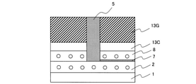
図3~7に、本発明に係る導電性部材の配置形態の他のバリエーションを示す。図3は、クッションゴム13Cが設けられていない例であり、導電性繊維7は、ベルト層2とトレッドゴム13Gとの間に配置されている。図4では、導電性繊維7は、クッションゴム13Cとトレッドゴム13Gとの間に配置されている。図5は、ベルト層2のタイヤ半径方向外側にキャップ層8が設けられている例であり、導電性繊維7は、キャップ層8とクッションゴム13Cとの間に配置されている。図6は、ベルト層2のタイヤ半径方向外側にキャップ層8が設けられており、導電性ゴム部5がキャップ層8を貫通してベルト層2に接している例であり、導電性繊維7は、キャップ層8とクッションゴム13Cとの間に配置されている。図7は、ベルト層2のタイヤ半径方向外側にキャップ層8が設けられており、導電性ゴム部5がキャップ層8を貫通してベルト層2に接している例であり、導電性繊維7は、クッションゴム13Cとトレッドゴム13Gとの間に配置されている。図8は、ベルト層2のタイヤ半径方向外側にキャップ層8が設けられており、導電性ゴム部5がキャップ層8を貫通してベルト層2に接している例であり、導電性繊維7は、ベルト層2とキャップ層8との間に配置されている。キャップ層8は、ゴム被覆された補強コードを実質的にタイヤ周方向に巻回することにより形成されるので、導電性ゴム部5は、図6~8に示すように、巻回されるキャップ層8の補強コードの間に挿入するようにして設けることもできる。
FIGS. 3 to 7 show other variations of the arrangement form of the conductive member according to the present invention. FIG. 3 shows an example in which the
図9に、図3に対応するベルト端クッションゴム4近傍の拡大部分断面図を示す。図示するように、この場合、導電性繊維7は、ベルト層2とトレッドゴム13Gとの間に配置されている。導電性ゴム部5のタイヤ半径方向内側端部から延びた導電性繊維7、および、ゴムチェーファー3から延びた導電性繊維7が、ベルト層2のタイヤ幅方向端部に配置されたベルト端クッションゴム4と導通することで、導電パスが確保されている。
FIG. 9 shows an enlarged partial cross-sectional view of the vicinity of the belt
図10に、導電性部材の配置形態の他のバリエーションに係る本発明の空気入りタイヤの他の例を示す幅方向片側断面図を示す。図10は、導電性部材が導電性繊維のみから構成されている以外の点は図1と同様であるので、共通する部分の説明は省略する。図示する配置形態においては、導電性繊維7のみで導電性ゴム部5からゴムチェーファー3までを導通させることができるので、ベルト端クッションゴム4は設けなくてもよく、また、設ける場合でも低ロス化が可能である。なお、本発明において導電性部材6は、ベルト層2のタイヤ幅方向端部よりもタイヤ半径方向内側の領域においては、サイドゴム12Gの内側に配置することができる。
FIG. 10 shows a one-sided cross-sectional view in the width direction showing another example of the pneumatic tire of the present invention according to another variation of the arrangement of the conductive member. FIG. 10 is the same as FIG. 1 except that the conductive member is composed of only conductive fibers, and thus the description of common parts will be omitted. In the illustrated arrangement, since the
本発明において、導電性部材6は導電性繊維7のみで構成しても導電性繊維7およびベルト端クッションゴム4により構成してもよく、導電性繊維7のみで構成した場合、軽量化が図れるというメリットがある。導電性部材6は、成型の自由度の観点から、複数に分割された部材の連結により構成することも可能である。
In the present invention, the
導電性繊維7は、繊維の形態のままで各部材間に配置してもよく、織物または編物のような集合体の形態で各部材間に配置してもよい。具体的には、成型時において導電性繊維7は、いずれかの部材の生ゴム表面に貼り付けて配置する他、ゴムにより被覆したシート状として各部材間に配置してもよく、配置条件に特に制限はない。
The
本発明に係る導電性部材6は、体積抵抗率が1×10⁸Ω・cm以下であることが必要であり、好適には1×10⁷Ω・cm以下であり、低いほど好ましい。導電性部材6の体積抵抗率が1×10⁸Ω・cmを超えると、タイヤ全体の電気抵抗を十分低減することができない。ここで、導電性部材6が複数の部材により構成されている場合には、複数の部材のそれぞれが体積抵抗率1×10⁸Ω・cm以下であることが必要である。
The
また、導電性繊維7の抵抗率は、単位長さ当たりの抵抗率である線抵抗率で、1×10⁷Ω/cm以下であることが好ましく、1×103Ω/cm以下であることがより好ましく、低いほどよい。導電性繊維7の線抵抗率を1×107Ω/cm以下とすることで、タイヤの電気抵抗の低減効果を良好に得ることができる。
Further, the resistivity of the
導電性繊維7としては、いかなる構造を有するものであってもよく、異なる種類の導電性繊維を組み合わせて用いてもよい。好適には、導電性繊維7として、導電部と非導電部とを有する複合繊維を用いることができる。このような導電性繊維7を構成する導電部としては、具体的には例えば、金属含有繊維、カーボン含有繊維、および、金属酸化物含有繊維などを挙げることができ、これらのうちのいずれか1種以上を用いることができる。ここで、本発明において金属含有繊維とは、金属含有量が5~100質量%である繊維をいい、金属および金属酸化物としては、例えば、ステンレス、スチール、アルミ、銅およびこれらの酸化物等が挙げられる。また、非導電部としては、綿、ナイロン、ポリエチレンテレフタレート(PET)等のポリエステル、および、ポリプロピレン(PP)などの有機物を挙げることができ、これらのうちのいずれか1種以上を用いることができる。これらの導電部と非導電部とからなる複合繊維は、良好な伸びを有し、密着性にも優れることから、タイヤ製造工程における応力負荷時や車両走行時における歪入力時にも破断することがなく、導電性繊維7として好ましく用いることができる。
The
本発明に用いる導電性繊維7中に占める導電部の質量比率としては、特に制限されないが、好適には10~90質量%、より好適には15~85質量%である。非導電部を上記比率で含むことで、導電性繊維7の伸びを良好に確保することができ、導電部を上記比率で含むことで、タイヤの電気抵抗の低減効果を良好に得ることができ、好ましい。
The mass ratio of the conductive portion in the
本発明における導電性繊維7としては、具体的には例えば、Bekaert社製のベキノックス(Bekinox、登録商標)や、クラレトレーディング(株)製のクラカーボ(登録商標)KC-500R、KC-793R等を用いることができる。
Specific examples of the
また、導電性繊維7の繊度としては、エア抜き性と導電性、耐久性を両立させる観点から、20~3000dtexとすることが好ましく、より好ましくは100~1000dtexであり、さらに好ましくは150~600dtexである。
Further, the fineness of the
本発明において、導電性繊維7は、繊維の形態のまま配置する場合、直線状に配置してもよく、ジグザグ状または波状に配置してもよい。また、本発明において、導電性繊維7は、タイヤ周方向に対し傾斜して配置するものであれば、トレッド部13からビード部11までの導電パスを確保することができるが、タイヤ周方向に対し60°~120°、さらにはタイヤ周方向に対し80°~110°となる方向に延在するよう配置されていることが好ましく、特には、タイヤ幅方向に延在するよう配置する。なお、導電性繊維7をジグザグ状または波状に配設する場合には、導電性繊維7が全体として延在する方向を、導電性繊維7の延在方向とする。
In the present invention, when the
なお、本発明において、導電性繊維7は、従来より加硫時のエア抜き目的で配置されているブリーダーコードに置換して設けることもできる。ブリーダーコードは、タイヤの生産工程で発生するエア入り不良を低減することを目的として、カーカスやベルト層の片面または両面に配置されるコード部材であり、一般に、綿糸やポリエステル糸等からなる。ブリーダーコードは、タイヤ生産工程においてタイヤ内に包含された空気を吸着、透過させ、エア入り不良を低減できるものである。カーカスに配置されるブリーダーコードのうちの一部または全部を導電性繊維7に置換することで、新たな部材の追加なしで、導電性繊維7の配置による効果を得ることができる。もちろん、ブリーダーコードはそのままで、導電性繊維7を追加して配置するものであっても、本発明の所期の効果を得ることができる。
In the present invention, the
導電性繊維7を、従来のブリーダーコードに代えて配置する場合、導電性繊維7は、ブリーダーコードのうち10~100質量%、好適には20~50質量%に代えて配設することができる。この程度の本数を導電性繊維7に置き換えれば、本発明の所期の効果を確実に得ることができる。
When the
本発明に用いる導電性繊維7は、紡績糸およびフィラメント糸のいずれであってもよいが、好適には、短繊維を紡績してなる紡績糸(混紡糸)とする。導電性繊維7とゴムとの接着性を確保するためには、導電性繊維7に対し、有機繊維とゴムとの間の接着を確保するための接着剤によるディップ処理を施すことが必要となるが、ディップ処理により導電性繊維7に接着剤の表面被覆を設けると、導電性繊維7を介してのエア抜き性が悪化する。そのため、導電性繊維7をブリーダーコードに代えて配置する際には、ディップ処理を一部分のみ施すことが好ましく、ディップ処理を施さないことがより好ましい。しかし、接着剤の表面被覆がない場合、導電性繊維7と未加硫ゴムとの密着力が小さくなって、製造時に抜け落ちてしまうことがある。この場合、紡績糸(混紡糸)を用いることで、短繊維のアンカー効果により、ディップ処理なしでもゴムとの密着性が確保でき、導電パスを確保しつつ、エア抜き性の効果も維持される点で好ましい。なお、フィラメント糸を用いる場合には、エア抜き性を保持するために撚りを加えることが好ましく、この場合の撚り数は、好適には10回/10cm以上、例えば、30~60回/10cmとすることができる。
The
一方、ブリーダーコードのうちの一部を導電性繊維7に置き換えるような場合には、例えば綿糸からなる残りのブリーダーコードにより、エア抜き性を確保することができるので、導電性繊維7がディップ処理されていても、ゴムとの密着性とエア抜き性とを両立することができる。よって、本発明においては、導電性繊維7は、ディップ処理されていてもよいが、ブリーダーコードをすべて導電性繊維7に置き換えるなど、設計の自由度を確保する観点からは、ディップ処理されていないことが好ましい。
On the other hand, when a part of the bleeder cord is replaced with the
導電性繊維7は、導電パスをタイヤ周方向にわたり確実に確保する観点から、タイヤ全体で少なくとも2本以上設けられていることが好ましい。
It is preferable that at least two or more
本発明においては、上記導電性部材6を設けたことで、例えば、ベルト層2のコーティングゴムの体積抵抗率を、1×10⁸Ω・cm以上、特には1×10¹⁰Ω・cm以上1×10¹³Ω・cm以下程度に低ロス化した場合や、カーカス1のコーティングゴムの体積抵抗率を、1×10⁸Ω・cm以上、特には1×10¹⁰Ω・cm以上1×10¹³Ω・cm以下程度に低ロス化した場合においても、タイヤの電気抵抗を低減することができるものである。
In the present invention, by providing the
本発明において、ゴムチェーファー3の体積抵抗率としては、1×10¹⁰Ω・cm以下であることが好ましく、1×10⁸Ω・cm以下であることがより好ましく、1×10⁷Ω・cm以下であることがさらに好ましく、低いほどよい。ゴムチェーファー3の体積抵抗率を上記範囲とすることで、タイヤの電気抵抗の低減効果を良好に得ることができる。
In the present invention, the volume resistivity of the
本発明において、導電性ゴム部5は、図示するように、通常、タイヤ赤道線CLの近傍に、少なくともトレッド踏面部からトレッドゴム13Gのタイヤ半径方向内側面までにわたり、タイヤ周方向の全周に設けることができる。すなわち、導電性ゴム部5は、トレッド踏面部から、トレッドゴム13Gを貫通するように設けられて、路面からタイヤ内部までの導電パスを形成する。
In the present invention, as shown in the figure, the
また、本発明においてクッションゴム13Cは、少なくともタイヤ赤道線CL上において、トレッドゴム13Gとベルト層2のコーティングゴム(キャップ層を設ける場合はキャップ層のコーティングゴム)との間に配置することができるゴム部材であり、通常、タイヤショルダー部付近まで延在しており、トレッドゴム13G、および、配設形態によってはサイドゴム12Gにも覆われるため、タイヤ外表面には露出しないゴム部材である。
Further, in the present invention, the
本発明においては、所定の導電性部材を配設した点のみが重要であり、これにより、本発明の所期の効果を得ることができるものであって、タイヤ構造の他の部分については、上方に従い適宜構成することができ、特に制限されるものではない。 In the present invention, it is important only that a predetermined conductive member is arranged, whereby the desired effect of the present invention can be obtained, and the other parts of the tire structure can be obtained. It can be appropriately configured according to the upper direction, and is not particularly limited.
例えば、図示するタイヤにおいて、カーカス1は、一対のビード部11間にそれぞれ埋設されたビードコア9の周りにタイヤ内側から外側に折り返され巻き上げられており、ビードコア9のタイヤ半径方向外側には、断面先細り状のビードフィラー10が配置されている。また、図示はしないが、本発明のタイヤにおいては、必要に応じ、ベルト層2のタイヤ半径方向外側に、ベルト層2の全体を覆うキャップ層や、ベルト層2の端部のみを覆うレイヤー層を、それぞれ1枚以上で配置することもできる。キャップ層およびレイヤー層は、通常、ゴム被覆された1本以上の補強コードを、実質的にタイヤ周方向に巻回することにより形成される。さらに、図示はしないが、タイヤの最内面には、通常、インナーライナーが配設されている。
For example, in the illustrated tire, the
以下、本発明を、実施例を用いてより詳細に説明する。
タイヤサイズ195/65R15にて、一対のビード部間に跨ってトロイド状に延在する1枚のカーカスプライからなるカーカスを骨格とし、そのクラウン部タイヤ半径方向外側に順次配置された2枚のベルト層、クッションゴムおよびトレッドゴムを備え、ビード部のタイヤ幅方向外表面にゴムチェーファー(体積抵抗率1×108Ω・cm)が配設された空気入りタイヤを製造した。また、ベルト層のタイヤ半径方向外側には、ベルト層を覆う幅でキャップ層が配置されており、ベルト層のタイヤ幅方向端部であってベルト層とカーカスとの間にはベルト端クッションゴム(体積抵抗率1×107Ω・cm)が配置され、トレッド部には、トレッドゴムをタイヤ表面の接地領域からタイヤ半径方向内側に向かって貫通して設けられる導電性ゴム部(体積抵抗率1×104Ω・cm)が配置されていた。
Hereinafter, the present invention will be described in more detail with reference to examples.
With a tire size of 195 / 65R15, a carcass consisting of one carcass ply extending in a toroid shape straddling between a pair of bead portions is used as a skeleton, and two belts sequentially arranged on the outer side of the crown portion in the radial direction of the tire. A pneumatic tire having a layer, cushion rubber and tread rubber and having a rubber chafer (
なお、カーカスのコーティングゴムは、体積抵抗率1×10¹²Ω・cmであり、ベルト層のコーティングゴムは、体積抵抗率1×10¹⁰Ω・cmであり、いずれも低ロスのゴム組成物が用いられていた。 The carcass coated rubber has a volume resistivity of 1 × 10 12 Ω · cm, and the belt layer coated rubber has a volume resistivity of 1 × 10 10 Ω · cm. It was used.
下記の表中に示す条件に従い導電性繊維を配置して、各実施例、参考例および比較例の供試タイヤを作製した。導電性繊維としては、線抵抗率が50Ω/cmであって、繊維径が400dtexであるBekaert社製のベキノックス(Bekinox)(登録商標、ポリエステル/金属繊維混紡糸)を用いて、タイヤ周方向において50mm間隔で配置した。 Conductive fibers were arranged according to the conditions shown in the table below to prepare test tires of Examples, Reference Examples and Comparative Examples. As the conductive fiber, Bekinox (registered trademark, polyester / metal fiber blended yarn) manufactured by Bekaert, which has a linear resistivity of 50 Ω / cm and a fiber diameter of 400 dtex, is used in the tire circumferential direction. They were arranged at intervals of 50 mm.
得られた各供試タイヤについて、電気抵抗値を下記に従い評価した。その結果を、下記の表中に示す。 The electric resistance value of each of the obtained test tires was evaluated according to the following. The results are shown in the table below.
(電気抵抗値)
タイヤの電気抵抗値は、GERMAN ASSOCIATION OF RUBBER INDUSTRYのWdK 110シート3に準拠して、ヒューレットパッカード(HEWLETT PACKARD)社製のモデルHP4394Aハイレジスタンスメーターを使用し、図11に示すようにして測定した。図中、符号111はタイヤ、112は鋼板、113は絶縁体、114はハイレジスタンスメーターであり、絶縁板113上の鋼板112とタイヤ111のリムとの間に1000Vの電流を流して測定した。
タイヤの電気抵抗値は、低いほど良好である。
(Electrical resistance value)
The electric resistance value of the tire was measured as shown in FIG. 11 using a model HP4394A high resistance meter manufactured by Hewlett-Packard (HEWLETT PACKARD) in accordance with WdK 110
The lower the electric resistance value of the tire, the better.
(転がり抵抗)
タイヤの転がり抵抗は、SAE J 1269に準拠して、転動抵抗試験機を用いて測定した。結果は、比較例1を基準とする指数にて示した。数値が大きいほど、転がり抵抗性能が良好であることを示している。
(Rolling resistance)
The rolling resistance of the tire was measured using a rolling resistance tester in accordance with SAE J 1269. The results are shown by an index based on Comparative Example 1. The larger the value, the better the rolling resistance performance.
これらの結果を、下記の表中に併せて示す。 These results are also shown in the table below.

*2)クッションゴムとして体積抵抗率1×10⁷Ω・cmのものを用いた場合を「なし」、1×10¹²Ω・cmのものを用いた場合を「あり」とした。
*3)ベルト端クッションゴムを設けない形態である。
* 2) The case where a cushion rubber having a volume resistivity of 1 × 10 7 Ω · cm was used was “none”, and the case where a cushion rubber having a volume resistivity of 1 × 10 12 Ω · cm was used was “yes”.
* 3) The belt end cushion rubber is not provided.
上記表中に示すように、所定の導電性部材を、導電性ゴム部のタイヤ半径方向内側端部からゴムチェーファーまでを導通可能に配置することで、キャップ層のコーティングゴムおよびクッションゴムについて低ロス化を図っても、タイヤの導電パスを確保することができ、タイヤの電気抵抗の上昇を防止できることが確かめられた。 As shown in the above table, by arranging the predetermined conductive member so as to be conductive from the inner end portion of the conductive rubber portion in the tire radial direction to the rubber chafer, the coating rubber and the cushion rubber of the cap layer are lowered. It was confirmed that the conductive path of the tire could be secured and the increase in the electric resistance of the tire could be prevented even if the loss was reduced.
1 カーカス
2 ベルト層
3 ゴムチェーファー
4 ベルト端クッションゴム
5 導電性ゴム部
6 導電性部材
7 導電性繊維
8 キャップ層
9 ビードコア
10 ビードフィラー
11 ビード部
12 サイドウォール部
12G サイドゴム
13 トレッド部
13G トレッドゴム
13C クッションゴム
20 リム
111 タイヤ
112 鋼板
113 絶縁体
114 ハイレジスタンスメーター
1
Claims (6)
前記カーカスと前記トレッドゴムとの間に少なくとも1枚のベルト層が配置され、該ベルト層のタイヤ幅方向端部であって該ベルト層と該カーカスとの間にベルト端クッションゴムが配置され、該ベルト層のタイヤ半径方向外側にキャップ層が設けられ、前記導電性ゴム部が、該キャップ層を貫通して該ベルト層に接しており、
前記導電性ゴム部のタイヤ半径方向内側端部から前記ゴムチェーファーまでを電気的に接続する導電性部材が配置され、該導電性部材が、導電性繊維および前記ベルト端クッションゴムからなるとともに、少なくとも該導電性ゴム部のタイヤ半径方向内側端部近傍および該ゴムチェーファー近傍における該導電性部材が該導電性繊維からなり、該導電性繊維が、タイヤ全体で少なくとも2本以上設けられており、かつ、該導電性部材の体積抵抗率が1×10⁸Ω・cm以下であることを特徴とする空気入りタイヤ。 The skeleton is a carcass composed of at least one carcass ply extending in a tread shape straddling between a pair of bead portions, and the tread rubber arranged on the outer side of the crown portion of the carcass in the radial direction of the tire and the tread rubber on the tire surface. In a pneumatic tire comprising a conductive rubber portion provided so as to penetrate inward in the tire radial direction from the ground contact region of the tire and a rubber chafer arranged on the outer surface of the bead portion in the tire width direction.
At least one belt layer is arranged between the carcass and the tread rubber, and a belt end cushion rubber is arranged at the end of the belt layer in the tire width direction between the belt layer and the carcass. A cap layer is provided on the outer side of the belt layer in the tire radial direction, and the conductive rubber portion penetrates the cap layer and is in contact with the belt layer.
A conductive member that electrically connects the inner end portion of the conductive rubber portion in the radial direction of the tire to the rubber chafer is arranged, and the conductive member is composed of a conductive fiber and the belt end cushion rubber, and also At least the conductive member in the vicinity of the inner end portion in the radial direction of the tire and the vicinity of the rubber chafer of the conductive rubber portion is made of the conductive fiber, and at least two or more of the conductive fibers are provided in the entire tire. Moreover, the pneumatic tire characterized in that the volumetric resistance of the conductive member is 1 × 10⁸ Ω · cm or less.
Priority Applications (5)
| Application Number | Priority Date | Filing Date | Title |
|---|---|---|---|
| JP2017238967A JP7002314B2 (en) | 2017-12-13 | 2017-12-13 | Pneumatic tires |
| PCT/JP2018/025412 WO2019116615A1 (en) | 2017-12-13 | 2018-07-04 | Pneumatic tire |
| EP18889722.7A EP3725568A4 (en) | 2017-12-13 | 2018-07-04 | Pneumatic tire |
| US16/900,135 US20200331308A1 (en) | 2017-12-13 | 2020-06-12 | Pneumatic tire |
| JP2021173459A JP7284795B2 (en) | 2017-12-13 | 2021-10-22 | pneumatic tire |
Applications Claiming Priority (1)
| Application Number | Priority Date | Filing Date | Title |
|---|---|---|---|
| JP2017238967A JP7002314B2 (en) | 2017-12-13 | 2017-12-13 | Pneumatic tires |
Related Child Applications (1)
| Application Number | Title | Priority Date | Filing Date |
|---|---|---|---|
| JP2021173459A Division JP7284795B2 (en) | 2017-12-13 | 2021-10-22 | pneumatic tire |
Publications (2)
| Publication Number | Publication Date |
|---|---|
| JP2019104424A JP2019104424A (en) | 2019-06-27 |
| JP7002314B2 true JP7002314B2 (en) | 2022-02-10 |
Family
ID=66819630
Family Applications (2)
| Application Number | Title | Priority Date | Filing Date |
|---|---|---|---|
| JP2017238967A Active JP7002314B2 (en) | 2017-12-13 | 2017-12-13 | Pneumatic tires |
| JP2021173459A Active JP7284795B2 (en) | 2017-12-13 | 2021-10-22 | pneumatic tire |
Family Applications After (1)
| Application Number | Title | Priority Date | Filing Date |
|---|---|---|---|
| JP2021173459A Active JP7284795B2 (en) | 2017-12-13 | 2021-10-22 | pneumatic tire |
Country Status (4)
| Country | Link |
|---|---|
| US (1) | US20200331308A1 (en) |
| EP (1) | EP3725568A4 (en) |
| JP (2) | JP7002314B2 (en) |
| WO (1) | WO2019116615A1 (en) |
Families Citing this family (4)
| Publication number | Priority date | Publication date | Assignee | Title |
|---|---|---|---|---|
| JP7002314B2 (en) | 2017-12-13 | 2022-02-10 | 株式会社ブリヂストン | Pneumatic tires |
| WO2019244349A1 (en) * | 2018-06-22 | 2019-12-26 | 横浜ゴム株式会社 | Pneumatic tire and assembly sheet |
| KR102267900B1 (en) * | 2019-09-24 | 2021-06-24 | 한국타이어앤테크놀로지 주식회사 | Non-pneumatic tire having fiber coated by metal salt |
| JP2023017521A (en) * | 2021-07-26 | 2023-02-07 | 株式会社ブリヂストン | tire |
Citations (11)
| Publication number | Priority date | Publication date | Assignee | Title |
|---|---|---|---|---|
| US20050087275A1 (en) | 2003-10-23 | 2005-04-28 | Zanzig David J. | Pneumatic tire with electrically conductive cord extending between a bead portion and a tread portion of the tire |
| JP2009040331A (en) | 2007-08-10 | 2009-02-26 | Sumitomo Rubber Ind Ltd | Tire |
| JP2009154608A (en) | 2007-12-25 | 2009-07-16 | Sumitomo Rubber Ind Ltd | Pneumatic tire |
| JP2011088458A (en) | 2009-10-20 | 2011-05-06 | Sumitomo Rubber Ind Ltd | Pneumatic tire |
| JP2013528525A (en) | 2010-06-18 | 2013-07-11 | コンティネンタル・ライフェン・ドイチュラント・ゲゼルシャフト・ミト・ベシュレンクテル・ハフツング | PNEUMATIC VEHICLE TIRE HAVING AIR EXHAUSION SLED AND METHOD FOR PRODUCING CONDUCTIVE COATING FOR AIR EXTRUSION SLED |
| JP2014133467A (en) | 2013-01-09 | 2014-07-24 | Sumitomo Rubber Ind Ltd | Pneumatic tire |
| JP2015123900A (en) | 2013-12-26 | 2015-07-06 | 横浜ゴム株式会社 | Pneumatic tire |
| JP2016033000A (en) | 2014-07-31 | 2016-03-10 | 横浜ゴム株式会社 | Pneumatic tire |
| WO2017122509A1 (en) | 2016-01-13 | 2017-07-20 | 株式会社ブリヂストン | Pneumatic tire |
| WO2017122821A1 (en) | 2016-01-13 | 2017-07-20 | 株式会社ブリヂストン | Pneumatic tire |
| WO2018011001A1 (en) | 2016-07-15 | 2018-01-18 | Nv Bekaert Sa | Electrically conductive yarn |
Family Cites Families (16)
| Publication number | Priority date | Publication date | Assignee | Title |
|---|---|---|---|---|
| JPS60182204U (en) * | 1984-05-15 | 1985-12-03 | 竹市 福平 | Automobile tires that discharge static electricity from the car body to the ground |
| JP4464917B2 (en) * | 2005-12-28 | 2010-05-19 | 住友ゴム工業株式会社 | Pneumatic tire |
| JP4348380B2 (en) * | 2007-05-29 | 2009-10-21 | 住友ゴム工業株式会社 | Pneumatic tire |
| DE602008003716D1 (en) * | 2007-06-15 | 2011-01-13 | Sumitomo Rubber Ind | tire |
| JP2009023504A (en) | 2007-07-19 | 2009-02-05 | Sumitomo Rubber Ind Ltd | Pneumatic tire |
| JP4249792B2 (en) | 2007-08-10 | 2009-04-08 | 住友ゴム工業株式会社 | tire |
| JP5295711B2 (en) * | 2007-11-01 | 2013-09-18 | 東洋ゴム工業株式会社 | Pneumatic tire |
| JP5570488B2 (en) * | 2011-10-14 | 2014-08-13 | 住友ゴム工業株式会社 | Pneumatic tire |
| JP5512724B2 (en) * | 2012-03-21 | 2014-06-04 | 住友ゴム工業株式会社 | Pneumatic tire |
| JP6040067B2 (en) * | 2013-03-21 | 2016-12-07 | 東洋ゴム工業株式会社 | Pneumatic tire manufacturing method and pneumatic tire |
| JP6130205B2 (en) | 2013-05-01 | 2017-05-17 | 住友ゴム工業株式会社 | Pneumatic tire |
| JP2015157547A (en) | 2014-02-24 | 2015-09-03 | 横浜ゴム株式会社 | pneumatic tire |
| JP6354515B2 (en) | 2014-10-20 | 2018-07-11 | 横浜ゴム株式会社 | Pneumatic tire |
| DE102015225149A1 (en) * | 2015-12-14 | 2017-06-14 | Continental Reifen Deutschland Gmbh | Vehicle tires |
| JP6758046B2 (en) | 2016-01-13 | 2020-09-23 | 株式会社ブリヂストン | Pneumatic tires |
| JP7002314B2 (en) | 2017-12-13 | 2022-02-10 | 株式会社ブリヂストン | Pneumatic tires |
-
2017
- 2017-12-13 JP JP2017238967A patent/JP7002314B2/en active Active
-
2018
- 2018-07-04 WO PCT/JP2018/025412 patent/WO2019116615A1/en unknown
- 2018-07-04 EP EP18889722.7A patent/EP3725568A4/en active Pending
-
2020
- 2020-06-12 US US16/900,135 patent/US20200331308A1/en not_active Abandoned
-
2021
- 2021-10-22 JP JP2021173459A patent/JP7284795B2/en active Active
Patent Citations (11)
| Publication number | Priority date | Publication date | Assignee | Title |
|---|---|---|---|---|
| US20050087275A1 (en) | 2003-10-23 | 2005-04-28 | Zanzig David J. | Pneumatic tire with electrically conductive cord extending between a bead portion and a tread portion of the tire |
| JP2009040331A (en) | 2007-08-10 | 2009-02-26 | Sumitomo Rubber Ind Ltd | Tire |
| JP2009154608A (en) | 2007-12-25 | 2009-07-16 | Sumitomo Rubber Ind Ltd | Pneumatic tire |
| JP2011088458A (en) | 2009-10-20 | 2011-05-06 | Sumitomo Rubber Ind Ltd | Pneumatic tire |
| JP2013528525A (en) | 2010-06-18 | 2013-07-11 | コンティネンタル・ライフェン・ドイチュラント・ゲゼルシャフト・ミト・ベシュレンクテル・ハフツング | PNEUMATIC VEHICLE TIRE HAVING AIR EXHAUSION SLED AND METHOD FOR PRODUCING CONDUCTIVE COATING FOR AIR EXTRUSION SLED |
| JP2014133467A (en) | 2013-01-09 | 2014-07-24 | Sumitomo Rubber Ind Ltd | Pneumatic tire |
| JP2015123900A (en) | 2013-12-26 | 2015-07-06 | 横浜ゴム株式会社 | Pneumatic tire |
| JP2016033000A (en) | 2014-07-31 | 2016-03-10 | 横浜ゴム株式会社 | Pneumatic tire |
| WO2017122509A1 (en) | 2016-01-13 | 2017-07-20 | 株式会社ブリヂストン | Pneumatic tire |
| WO2017122821A1 (en) | 2016-01-13 | 2017-07-20 | 株式会社ブリヂストン | Pneumatic tire |
| WO2018011001A1 (en) | 2016-07-15 | 2018-01-18 | Nv Bekaert Sa | Electrically conductive yarn |
Also Published As
| Publication number | Publication date |
|---|---|
| JP2022002966A (en) | 2022-01-11 |
| JP2019104424A (en) | 2019-06-27 |
| JP7284795B2 (en) | 2023-05-31 |
| EP3725568A4 (en) | 2021-07-14 |
| EP3725568A1 (en) | 2020-10-21 |
| US20200331308A1 (en) | 2020-10-22 |
| WO2019116615A1 (en) | 2019-06-20 |
Similar Documents
| Publication | Publication Date | Title |
|---|---|---|
| JP6726217B2 (en) | Pneumatic tire | |
| JP6758046B2 (en) | Pneumatic tires | |
| JP7284795B2 (en) | pneumatic tire | |
| JP6075285B2 (en) | Pneumatic tire | |
| JP5512724B2 (en) | Pneumatic tire | |
| JP4575979B2 (en) | Pneumatic tire and manufacturing method thereof | |
| JP2014133467A (en) | Pneumatic tire | |
| JP2019081401A (en) | Pneumatic tire | |
| JP5512727B2 (en) | Pneumatic tire | |
| JP5512726B2 (en) | Pneumatic tire | |
| CN113165439B (en) | Tyre for vehicle wheels | |
| JP2011156887A (en) | Pneumatic radial tire and method for manufacturing the same | |
| JP5104047B2 (en) | Pneumatic radial tire | |
| US20200298632A1 (en) | Pneumatic tire | |
| JP5512725B2 (en) | Pneumatic tire | |
| JP2015205528A (en) | pneumatic tire | |
| JP6354429B2 (en) | Pneumatic tire | |
| JP2023084587A (en) | tire | |
| KR102326574B1 (en) | Tire improved discharging property of static electricity | |
| JP2009202643A (en) | Pneumatic radial tire | |
| JP2014201136A (en) | Pneumatic tire | |
| JP2023089367A (en) | tire |
Legal Events
| Date | Code | Title | Description |
|---|---|---|---|
| A621 | Written request for application examination |
Free format text: JAPANESE INTERMEDIATE CODE: A621 Effective date: 20200706 |
|
| A131 | Notification of reasons for refusal |
Free format text: JAPANESE INTERMEDIATE CODE: A131 Effective date: 20210413 |
|
| A521 | Request for written amendment filed |
Free format text: JAPANESE INTERMEDIATE CODE: A523 Effective date: 20210611 |
|
| A131 | Notification of reasons for refusal |
Free format text: JAPANESE INTERMEDIATE CODE: A131 Effective date: 20210824 |
|
| A521 | Request for written amendment filed |
Free format text: JAPANESE INTERMEDIATE CODE: A523 Effective date: 20211022 |
|
| TRDD | Decision of grant or rejection written | ||
| A01 | Written decision to grant a patent or to grant a registration (utility model) |
Free format text: JAPANESE INTERMEDIATE CODE: A01 Effective date: 20211221 |
|
| A61 | First payment of annual fees (during grant procedure) |
Free format text: JAPANESE INTERMEDIATE CODE: A61 Effective date: 20211227 |
|
| R150 | Certificate of patent or registration of utility model |
Ref document number: 7002314 Country of ref document: JP Free format text: JAPANESE INTERMEDIATE CODE: R150 |