JP7001381B2 - Alignment method, film formation method, manufacturing method of electronic device using it, alignment device, and manufacturing device of electronic device equipped with it. - Google Patents
Alignment method, film formation method, manufacturing method of electronic device using it, alignment device, and manufacturing device of electronic device equipped with it. Download PDFInfo
- Publication number
- JP7001381B2 JP7001381B2 JP2017138326A JP2017138326A JP7001381B2 JP 7001381 B2 JP7001381 B2 JP 7001381B2 JP 2017138326 A JP2017138326 A JP 2017138326A JP 2017138326 A JP2017138326 A JP 2017138326A JP 7001381 B2 JP7001381 B2 JP 7001381B2
- Authority
- JP
- Japan
- Prior art keywords
- substrate
- mask
- alignment
- film
- clamp
- Prior art date
- Legal status (The legal status is an assumption and is not a legal conclusion. Google has not performed a legal analysis and makes no representation as to the accuracy of the status listed.)
- Active
Links
- 238000000034 method Methods 0.000 title claims description 47
- 238000004519 manufacturing process Methods 0.000 title claims description 25
- 230000015572 biosynthetic process Effects 0.000 title claims description 18
- 239000000758 substrate Substances 0.000 claims description 312
- 239000010408 film Substances 0.000 claims description 80
- 238000003825 pressing Methods 0.000 claims description 24
- 238000000926 separation method Methods 0.000 claims 2
- 238000007736 thin film deposition technique Methods 0.000 claims 1
- 238000000427 thin-film deposition Methods 0.000 claims 1
- 239000010410 layer Substances 0.000 description 44
- 230000003028 elevating effect Effects 0.000 description 31
- 210000000078 claw Anatomy 0.000 description 21
- 239000000463 material Substances 0.000 description 10
- 230000005525 hole transport Effects 0.000 description 8
- 238000005192 partition Methods 0.000 description 8
- 238000013519 translation Methods 0.000 description 8
- 238000007740 vapor deposition Methods 0.000 description 7
- 230000001965 increasing effect Effects 0.000 description 6
- 238000012546 transfer Methods 0.000 description 6
- QVGXLLKOCUKJST-UHFFFAOYSA-N atomic oxygen Chemical compound [O] QVGXLLKOCUKJST-UHFFFAOYSA-N 0.000 description 4
- 238000010586 diagram Methods 0.000 description 4
- 238000005259 measurement Methods 0.000 description 4
- 239000001301 oxygen Substances 0.000 description 4
- 229910052760 oxygen Inorganic materials 0.000 description 4
- 238000012545 processing Methods 0.000 description 4
- 239000011888 foil Substances 0.000 description 3
- 239000011241 protective layer Substances 0.000 description 3
- 239000004925 Acrylic resin Substances 0.000 description 2
- 229920000178 Acrylic resin Polymers 0.000 description 2
- 238000005452 bending Methods 0.000 description 2
- 238000006073 displacement reaction Methods 0.000 description 2
- 230000006870 function Effects 0.000 description 2
- 239000002184 metal Substances 0.000 description 2
- 239000012044 organic layer Substances 0.000 description 2
- 238000004544 sputter deposition Methods 0.000 description 2
- 238000003860 storage Methods 0.000 description 2
- 239000010409 thin film Substances 0.000 description 2
- 238000005229 chemical vapour deposition Methods 0.000 description 1
- 239000003086 colorant Substances 0.000 description 1
- 230000007547 defect Effects 0.000 description 1
- 239000000428 dust Substances 0.000 description 1
- 230000000694 effects Effects 0.000 description 1
- 239000005357 flat glass Substances 0.000 description 1
- 239000011521 glass Substances 0.000 description 1
- 230000005484 gravity Effects 0.000 description 1
- 238000005286 illumination Methods 0.000 description 1
- 239000011261 inert gas Substances 0.000 description 1
- 230000000977 initiatory effect Effects 0.000 description 1
- 229910010272 inorganic material Inorganic materials 0.000 description 1
- 239000011147 inorganic material Substances 0.000 description 1
- 230000001678 irradiating effect Effects 0.000 description 1
- 238000001459 lithography Methods 0.000 description 1
- 239000011159 matrix material Substances 0.000 description 1
- 229910044991 metal oxide Inorganic materials 0.000 description 1
- 150000004706 metal oxides Chemical class 0.000 description 1
- 230000003287 optical effect Effects 0.000 description 1
- 239000011368 organic material Substances 0.000 description 1
- 230000000149 penetrating effect Effects 0.000 description 1
- 238000005268 plasma chemical vapour deposition Methods 0.000 description 1
- 239000011347 resin Substances 0.000 description 1
- 229920005989 resin Polymers 0.000 description 1
- 230000000452 restraining effect Effects 0.000 description 1
- 238000004528 spin coating Methods 0.000 description 1
Images


Description
本発明は、基板とマスクとのアライメント方法と、マスクを用いて基板の上にパターン状の膜を形成する成膜方法、パターン状の膜を有する電子デバイスの製造方法、アライメント装置、及び、それを備えた電子デバイスの製造装置に関する。 The present invention relates to an alignment method between a substrate and a mask, a film forming method for forming a patterned film on a substrate using a mask, a method for manufacturing an electronic device having a patterned film, an alignment device, and the like. The present invention relates to an electronic device manufacturing apparatus equipped with .
有機EL素子などの電子デバイスの製造では、基板の被成膜面を下向きにして水平に保持し、基板上に形成する膜のパターンに応じた開口を有するマスクを用いた成膜が行われている。基板の被成膜面を下向きにして成膜を行う場合、なるべく成膜を妨げないよう基板は端部で支持されるため、基板の中央部が自重で下方に凸形状に撓んだ状態となる。 In the manufacture of electronic devices such as organic EL elements, film formation is performed using a mask that holds the substrate to be filmed facing down and holds it horizontally and has openings according to the pattern of the film formed on the substrate. There is. When film formation is performed with the surface to be filmed on the substrate facing downward, the substrate is supported by the edges so as not to interfere with film formation as much as possible. Become.
基板の所定位置に膜を形成するために、基板とマスクとの相対位置合わせ(アライメント)が行われる。具体的には、基板とマスクとが接触しない位置関係に配置して、撮像装置を用いて基板のアライメントマークとマスクのアライメントマークとの位置合わせを行った後、基板とマスクとを近づけ、基板をマスクの上に載置する。この状態で基板のアライメントマークとマスクのアライメントマークとのずれ量が所定の範囲内に収まると、アライメントは完了する。 Relative alignment between the substrate and the mask is performed in order to form a film at a predetermined position on the substrate. Specifically, they are arranged in a positional relationship in which the substrate and the mask do not come into contact with each other, and after aligning the alignment mark of the substrate and the alignment mark of the mask using an image pickup device, the substrate and the mask are brought close to each other to bring the substrate closer to the substrate. Place on the mask. In this state, when the amount of deviation between the alignment mark on the substrate and the alignment mark on the mask is within a predetermined range, the alignment is completed.
基板中央部が自重で下方に撓んだ状態で基板とマスクとが接触しない位置関係に設置すると、基板の端部において、基板とマスク間の距離が最も長くなる。基板とマスク間の距離が長いと、撮像装置の焦点は基板およびマスクのいずれか一方にしか合わせられなくなる。一般に、アライメントマークは基板およびマスクそれぞれの端部に設けられているため、基板の撓みが大きいと、基板とマスクのアライメントマークを同時に計測できなくなり、基板とマスクとの位置合わせが困難になるという課題が生じる。特に、近年は基板の大型化、薄型化が進んでいるため基板の撓みが大きくなり、ますますアライメントが困難になっている。 If the central portion of the substrate is bent downward due to its own weight and installed in a positional relationship in which the substrate and the mask do not come into contact with each other, the distance between the substrate and the mask becomes the longest at the end of the substrate. If the distance between the substrate and the mask is long, the image pickup device can only be focused on either the substrate or the mask. Generally, the alignment mark is provided at the end of each of the substrate and the mask, so if the deflection of the substrate is large, the alignment mark of the substrate and the mask cannot be measured at the same time, and it becomes difficult to align the substrate and the mask. Challenges arise. In particular, in recent years, as the size and thickness of the substrate have been increasing, the deflection of the substrate has increased, and alignment has become more difficult.
特許文献1には、被成膜面である一主面の縁で支持された基板に、他主面の全域を覆う状態で基板押さえ部を載置するアライメント装置が開示されている。このように基板を保持することにより、基板押さえ部のマス(重力または慣性)を利用したアライメントが可能となり、基板が暴れてしまう現象を回避でき、基板の位置ずれを防止することができると記載されている。 Patent Document 1 discloses an alignment device in which a substrate holding portion is placed on a substrate supported by the edge of one main surface, which is the surface to be film-formed, so as to cover the entire other main surface. It is stated that by holding the board in this way, alignment using the mass (gravity or inertia) of the board holding portion is possible, the phenomenon that the board is violent can be avoided, and the misalignment of the board can be prevented. Has been done.
特許文献1によれば、基板押さえ部によって基板の端部が押さえられることにより、梃子の原理によって基板のたわみ量が低減され、基板とマスクのアライメントマークを同時に計測することが可能となる。 According to Patent Document 1, since the end portion of the substrate is pressed by the substrate pressing portion, the amount of deflection of the substrate is reduced by the principle of leverage, and the alignment mark of the substrate and the mask can be measured at the same time.
しかし、基板の撓みは、低減できても無くすことはできない。そのため、アライメントの後に基板とマスクとを互いに近付けていくと、まず撓んだ中央部がマスクに接触し、次いで中央部の周辺に向かって接触領域が拡大して略全面が接触することになる。接触領域には、基板とマスクとの間に摩擦力が生じるため、基板中央部に生じる摩擦力による拘束と基板端部の基板押さえ部による拘束とによって、基板の自由な動きが妨げられる。そのような状態でさらに基板とマスクとを近づけていくと、マスクの形状に合わせて基板の形状が変化し、基板には大きな歪が生じる。 However, even if the deflection of the substrate can be reduced, it cannot be eliminated. Therefore, when the substrate and the mask are brought closer to each other after alignment, the bent central portion first contacts the mask, and then the contact region expands toward the periphery of the central portion so that almost the entire surface is in contact. .. Since a frictional force is generated between the substrate and the mask in the contact region, the free movement of the substrate is hindered by the restraint by the frictional force generated in the central portion of the substrate and the restraint by the substrate holding portion at the end of the substrate. If the substrate and the mask are brought closer to each other in such a state, the shape of the substrate changes according to the shape of the mask, and the substrate is greatly distorted.
基板の歪みがある程度大きくなると、歪みは拘束力が比較的弱い箇所で解消され、基板とマスクとの相対位置がずれる。基板とマスクとの相対位置ずれの大きさや方向が一定であれば、相対位置ずれを考慮してアライメントを行うことができる。しかし、基板の個性や基板を保持する位置の微妙な変化に起因して、基板が変わる度に撓みの形状や歪みが解消される位置が異なる。許文献1では個々の基板の撓み形状のついては考慮されていないため、基板毎に基板とマスクとの相対位置ずれの方向や大きさが異なり、相対位置ずれを考慮したアライメントを行うのは困難である。 When the strain of the substrate becomes large to some extent, the strain is eliminated at the place where the binding force is relatively weak, and the relative position between the substrate and the mask shifts. If the magnitude and direction of the relative positional deviation between the substrate and the mask are constant, the alignment can be performed in consideration of the relative positional deviation. However, due to the individuality of the substrate and the subtle changes in the position where the substrate is held, the shape of the deflection and the position where the distortion is eliminated are different each time the substrate is changed. Since the bending shape of each substrate is not taken into consideration in License Document 1, the direction and magnitude of the relative positional deviation between the substrate and the mask are different for each substrate, and it is difficult to perform alignment considering the relative positional deviation. be.
そこで、本発明は、自重によって撓んだ状態の基板をマスクに載置する際に生じる、基板とマスクとの相対位置ずれの再現性を向上させ、精度の高いアライメントを実現することを目的とする。 Therefore, an object of the present invention is to improve the reproducibility of the relative positional deviation between the substrate and the mask, which occurs when the substrate bent by its own weight is placed on the mask, and to realize highly accurate alignment. do.
上記目的を達成するために、本発明にかかる基板とマスクとのアライメント方法は、基板の第1の部分が載置される第1の基板載置部と、前記第1の基板載置部に対向して前記基板の前記第1の部分を押圧する第1の押圧部と、を有し、前記第1の部分をクランプする第1のクランプ部と、前記基板の前記第1の部分とは異なる第2の部分が載置される第2の基板載置部と、前記第2の基板載置部に対向して前記基板の前記第2の部分を押圧する第2の押圧部と、を有し、前記第2の部分をクランプする第2のクランプ部と、を備えたアライメント装置におけるアライメント方法であって、前記第1のクランプ部が前記第1の部分をクランプし、かつ、前記第2のクランプ部が前記第2の部分をクランプする状態で、前記基板とマスクとの面内における相対位置を調整するアライメント工程と、前記アライメント工程の後に、前記基板の一部が前記マスクに接触し、かつ、前記面と交差する前記基板の厚み方向における前記第1の基板載置部と前記第2の基板載置部との高さの差が、前記アライメント工程のときの前記高さの差よりも大きい状態において、前記第1の押圧部と前記第2の押圧部とを前記基板から離間する離間工程と、を有することを特徴とする。
In order to achieve the above object, the method of aligning the substrate and the mask according to the present invention is performed on the first substrate mounting portion on which the first portion of the substrate is mounted and the first substrate mounting portion. A first clamping portion having a first pressing portion for pressing the first portion of the substrate facing each other and clamping the first portion, and the first portion of the substrate A second substrate mounting portion on which a different second portion is mounted and a second pressing portion that faces the second substrate mounting portion and presses the second portion of the substrate. It is an alignment method in an alignment apparatus including a second clamp portion that has and clamps the second portion, wherein the first clamp portion clamps the first portion and the first portion is provided. After the alignment step of adjusting the relative position of the substrate and the mask in the plane and the alignment step in a state where the clamp portion of 2 clamps the second portion, a part of the substrate comes into contact with the mask. Moreover, the difference in height between the first substrate mounting portion and the second substrate mounting portion in the thickness direction of the substrate intersecting the surface is the height at the time of the alignment step. It is characterized by having a separating step of separating the first pressing portion and the second pressing portion from the substrate in a state larger than the difference .
本発明によれば、基板をマスクに載置する際の相対位置ずれの再現性を高め、アライメント精度を向上させることができる。 According to the present invention, it is possible to improve the reproducibility of the relative positional deviation when the substrate is placed on the mask and improve the alignment accuracy.
以下、図面を参照しつつ本発明の好適な実施形態を説明する。ただし、以下で説明する実施形態は本発明の好ましい構成を例示的に示すものにすぎず、本発明の範囲をそれらの構成に限定されない。以下の説明における、装置のハードウェア構成及びソフトウェア構成、処理フロー、製造条件、寸法、材質、形状などは、特定的な記載がないかぎりは、本発明の範囲をそれらのみに限定する趣旨のものではない。 Hereinafter, preferred embodiments of the present invention will be described with reference to the drawings. However, the embodiments described below merely illustrate preferred configurations of the present invention, and the scope of the present invention is not limited to those configurations. Unless otherwise specified, the hardware configuration and software configuration, processing flow, manufacturing conditions, dimensions, materials, shapes, etc. of the apparatus in the following description are intended to limit the scope of the present invention to those. is not it.
本発明は、基板とマスクとのアライメント技術に関し、平行平板の基板の表面に真空蒸着により所望のパターンの薄膜(材料層)を形成する際に好ましく適用できる。基板の材料としては、ガラス、樹脂、金属などの任意の材料を選択でき、また、蒸着材料としても、有機材料、無機材料(金属、金属酸化物など)などの任意の材料を選択できる。本発明の技術は、具体的には、電子デバイス(例えば、有機ELパネル、薄膜太陽電池)の製造に適用可能である。なかでも、有機ELパネルの製造には、基板の大型化あるいは表示パネルの高精細化により基板とマスクのアライメント精度のさらなる向上が要求されているため、本発明の好ましい適用例の一つである。 INDUSTRIAL APPLICABILITY The present invention relates to an alignment technique between a substrate and a mask, and can be preferably applied when forming a thin film (material layer) having a desired pattern on the surface of a parallel plate substrate by vacuum vapor deposition. As the substrate material, any material such as glass, resin, and metal can be selected, and as the vapor deposition material, any material such as an organic material and an inorganic material (metal, metal oxide, etc.) can be selected. Specifically, the technique of the present invention can be applied to the manufacture of electronic devices (for example, organic EL panels, thin-film solar cells). In particular, in the manufacture of an organic EL panel, it is required to further improve the alignment accuracy between the substrate and the mask by increasing the size of the substrate or increasing the definition of the display panel, which is one of the preferable application examples of the present invention. ..
(アライメント装置および成膜装置)
本発明の実施形態に係るアライメント方法およびそれを用いた成膜方法を、図面に基づき説明する。同一もしくは対応する部材を複数有する場合、図面中にa、bなどの添え字を付与しているが、特定の部材を指す場合を除いて、a、bなどの添え字を省略して説明する。
(Alignment device and film forming device)
The alignment method according to the embodiment of the present invention and the film forming method using the same will be described with reference to the drawings. When there are a plurality of identical or corresponding members, subscripts such as a and b are added in the drawings, but the subscripts such as a and b are omitted except when referring to a specific member. ..
図1に、電子デバイスの製造装置の一例を示す。図1に示すように、複数の成膜装置111、112と、搬送室110と、を有する。搬送室110内には、基板5を保持し搬送する搬送ロボット119が設けられている。搬送ロボット119は、例えば、多関節アームに、基板を保持するロボットハンドが取り付けられた構造をもつロボットであり、各成膜室への基板5の搬入/搬出を行う。製造装置は、成膜装置を3つ以上有していても良いし、他の処理を行う処理室がさらに連結されていても良い。
FIG. 1 shows an example of an electronic device manufacturing apparatus. As shown in FIG. 1, it has a plurality of
搬送ロボット119との基板5の受け渡し、基板5とマスクの相対位置の調整(アライメント)、マスク上への基板5の固定、成膜などの一連の成膜プロセスは、不図示の制御部によって自動で行うことができる。各成膜装置は、成膜源の違いやマスクの違いなど細かい点で相違する部分はあるものの、基本的な構成(特に基板の搬送やアライメントに関わる構成)はほぼ共通している。以下、成膜装置の共通構成について説明する。
A series of film formation processes such as transfer of the
本発明にかかるアライメント方法が適用される成膜装置の概念図を図1に示す。 FIG. 1 shows a conceptual diagram of a film forming apparatus to which the alignment method according to the present invention is applied.
成膜装置は、基板5に成膜材料を形成するための成膜空間2を有する成膜チャンバ4、基板5を成膜チャンバ4内に搬入/搬出するためのゲートバルブ15、基板5およびマスク6を保持して相対位置合わせを行うアライメント装置1を備えている。成膜チャンバ1の成膜空間2には、成膜材料を備える成膜源(蒸着源)7を設置するための機構が設けられている。図1には、蒸着装置を示しているが、本発明は、スパッタリング法やCVD法など、蒸着法以外の成膜方法にも適用することが可能である。
The film forming apparatus includes a film forming chamber 4 having a
アライメント装置1は、成膜チャンバ4の上部隔壁(天板)3の上に搭載されており、位置決め機構と、基板保持部8と、マスク保持部9とを有している。位置決め機構は、XYθz方向に駆動する回転並進機構11と、Z昇降ベース13と、Z昇降ベース13の側面に固定されるZガイド18に沿って移動するZ昇降スライダ10を含んでおり、成膜チャンバ2の外側に設けられている。可動部を多く含む位置決め機構を成膜空間の外に配置することで、成膜空間内の発塵を抑制することができる。
The alignment device 1 is mounted on the upper partition wall (top plate) 3 of the film forming chamber 4, and has a positioning mechanism, a
Z昇降スライダ10には、基板保持シャフト12が固定されている。基板保持シャフト12は、成膜チャンバ4の上部隔壁3に設けられた貫通穴16を介して、成膜チャンバ4の外部と内部にわたって設けられている。そして、成膜空間2において、基板保持シャフト12の下部に基板保持部8が設けられ、被成膜物である基板5を保持することが可能となっている。
A
基板保持シャフト12と上部隔壁3とが干渉することのないよう、貫通穴16は基板保持シャフト12の外径に対して十分に大きく設計される。また、基板保持シャフト12は、貫通穴16を通り、成膜チャンバ4の外側のZ昇降スライダ10に固定されるまでの間、Z昇降スライダ10と上部隔壁3とに端部が固定されたベローズ40によって覆われる。つまり、基板保持シャフト12は、成膜チャンバ4と連通する閉じられた空間によって覆われるため、基板保持シャフト12全体を成膜空間2と同じ状態(例えば、真空状態)に保つことができる。ベローズ40には、Z方向およびXY方向にも柔軟性を持つものを用いるとよい。アライメント装置1の稼働によってベローズ40が変位した際に発生する抵抗力を十分に小さくすることができ、位置調整時の負荷を低減することができる。
The through
マスク保持部9は、成膜チャンバ4の内部において、上部隔壁3の成膜空間側の面に設置されており、マスクを保持することが可能となっている。有機ELパネルの製造に広く用いられるマスク6は、成膜パターンに応じた開口を有するマスク箔6aが、剛性の高いマスク枠6bに架張された状態で固定された構成を有しており、マスク6は撓みの小さい状態で保持される。
The mask holding portion 9 is installed on the surface of the
位置決め機構、基板保持機構8、成膜源の一連の動作は、制御部50によって制御される。制御部50は、例えば、プロセッサ、メモリ、ストレージ、I/Oなどを有するコンピュータにより構成可能である。この場合、制御部50の機能は、メモリ又はストレージに記憶されたプログラムをプロセッサが実行することにより実現される。コンピュータとしては、汎用のパーソナルコンピュータを用いてもよいし、組込型のコンピュータ又はPLC(programmable logic controller)を用いてもよい。あるいは、制御部270の機能の一部又は全部をASICやFPGAのような回路で構成してもよい。なお、図1に示した電子デバイス製造装置の場合、成膜装置ごとに制御部50が設けられていてもよいし、1つの制御部50が複数の成膜装置を制御してもよい。
A series of operations of the positioning mechanism, the
次にアライメント装置1の位置決め機構の詳細について、図3を用いて説明する。 Next, the details of the positioning mechanism of the alignment device 1 will be described with reference to FIG.
図3は、アライメント機構の一形態を示す斜視図である。Z昇降スライダ10を鉛直Z方向に案内するガイドは、複数本のZガイド18a~18dを含んでおり、Z昇降ベース13の側面に固定されている。Z昇降スライダ中央には駆動力を伝達するためのボールネジ20が配設され、Z昇降ベース13に固定されたモータ19から伝達される動力が、ボールネジ20を介してZ昇降スライダ10に伝えられる。
FIG. 3 is a perspective view showing one form of the alignment mechanism. The guide that guides the
モータ19は不図示の回転エンコーダを内蔵しており、エンコーダの回転数により間接的にZ昇降スライダ10のZ方向位置を計測することが可能となっている。従って、モータ19の駆動をエンコーダによる計測値に基づいて制御すれば、Z昇降スライダ10のZ方向の精密な位置決めを行うことができる。なお、Z昇降スライダ10の昇降機構は、ボールネジ20と回転エンコーダに限定されるものではなく、リニアモータとリニアエンコーダの組み合わせなど、公知の機構を採用することができる。
The motor 19 has a built-in rotary encoder (not shown), and it is possible to indirectly measure the Z direction position of the
図4は、回転並進機構11の一形態を示す斜視図である。Z昇降スライダ10およびZ昇降ベース13が回転並進機構11の上に配設されており、Z昇降ベース13とZ昇降スライダ10の全体を、XYθz方向に駆動させることが可能となっている。
FIG. 4 is a perspective view showing one form of the
回転並進機構11は複数の駆動ユニット21a~21dを有している。図4の構成では、駆動ユニット21a~21dは、それぞれベースの四隅に配置されており、隣接する隅に配置された駆動ユニットをZ軸周りに90度回転させた向きに配置されている。
The
各駆動ユニット21は、駆動力を発生させるモータ41を備えている。さらに、モータ41の力がボールネジ42を介して伝達されることにより第1の方向にスライドする第1のガイド22と、XY平面において第1の方向と直交する第2の方向にスライドする第2のガイド23とを備えている。さらに、Z軸周りに回転可能な回転ベアリング24を備えている。例えば、駆動ユニット21cの場合は、X方向にスライドする第1のガイド22、X方向と直交するY方向にスライドする第2のガイド23、回転ベアリング24を有しており、Xモータ41の力がボールネジ42を介して第1のガイド22に伝達される。
Each drive unit 21 includes a
モータ41は不図示の回転エンコーダを内蔵しており、第1のガイド22の変位量を計測可能である。従って、各駆動ユニット21において、計測した第1のガイド22の変位量に基づいてモータ41の駆動を制御部50で制御することにより、Z昇降ベース13のXYθz方向における位置を精密に制御することができる。
The
Z昇降ベース13を+X方向へ移動させる場合は、駆動ユニット21bと21cのそれぞれにおいて+X方向にスライドさせる力をモータ41で発生させ、Z昇降ベース13にその力を伝えるとよい。また、+Y方向へ移動させる場合には、駆動ユニット21aと21dのそれぞれにおいて+Y方向にスライドさせる力をモータ41で発生させ、Z昇降ベース13にその力を伝えるとよい。Z昇降ベース13を+θz回転(時計周りにθz回転)させる場合は、対角に配置された駆動ユニット21cと21bとを用いて、Z軸周りに+θz回転させるために必要な力を発生させ、Z昇降ベース13にその力を伝えるとよい。あるいは、駆動ユニット21aと21dとを用いて、Z昇降ベース13に回転に必要な力を伝えてもよい。
When moving the
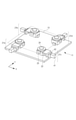
次に、本発明にかかる基板保持部8の詳細な構成について、図5を用いて説明する。図5(a)は矩形の基板5を保持した状態の基板保持部8全体を、アライメント機構1側から見た斜視図である。図5(b)、(c)は、基板保持部8が基板と接する部分を拡大した図である。それぞれ、基板を挟持せずに保持した状態と、基板をクランプ27で挟持して固定した状態と、を示している。
Next, the detailed configuration of the
図5(a)~(c)に示すように、基板保持部8は基板保持シャフト12a~12dの下部に固定されている。基板保持部8は、基板保持シャフト12によって位置が制御される保持部ベース25に設けられた複数の受け爪26と、受け爪26と対向して配置された複数のクランプ27を有している。基板5は、一対の長辺にて、被成膜面である第1の主面側が受け爪26に接する向きに、基板保持部8に載置される。
As shown in FIGS. 5A to 5C, the
本発明が適用されるアライメント装置は、保持部ベース25aの位置を制御するための基板保持シャフト12a、12bと、
保持部ベース25bの位置を制御するための基板保持シャフト12c、12dとは、別々に位置が制御可能となっている。図5では、矩形の基板5を保持する保持部ベース25を、基板5の対向する長辺を保持する2つの部材としているが、これに限定されるものではない。保持部ベース25a、25bをさらに複数に分割し、それぞれを個別に駆動制御可能な構成としてもよい。
The alignment device to which the present invention is applied includes
The position can be controlled separately from the
クランプ27は、基板5の第1の主面とは反対側の第2の主面に接して、基板5に対して受け爪26側に押圧を加える部材である。基板5の縁を受け爪26とクランプ27とによって挟み込むことによって、基板の位置を固定し、かつ、基板の撓みを低減した状態で保持することができる。
The
クランプ27は、それぞれが個別に設けられた駆動機構によって上下に駆動されてもよいが、ここでは保持部ベース25ごとに複数のクランプ27を1つのユニットとし、ユニットごとに駆動機構で駆動する場合について説明する。複数のクランプ27を含むクランプユニット28はクランプスライダ32に固定されており、基板保持部8の保持部ベース25と保持部上板35の間に配設されたリニアブッシュ39によって、クランプスライダ32がZ方向にガイドされる。クランプスライダ32は、上部隔壁3を貫通する駆動シャフト34を介してZ昇降スライダ10に固定される。クランプスライダ32は駆動シャフト34を介して電動シリンダ36の力が伝えられZ方向に駆動させることができる。
The
クランプ27の下降し、クランプ27が受け爪26上に搭載された基板5の第2の主面側に当接すると、受け爪26とクランプ27とで基板5を両側から固定した、図5(b)の状態となる。クランプ27によって一定の荷重を基板5に付加するため、クランプ27の上部には保持力(荷重)を発生するためのバネ29が配設される。なおクランプ27とバネ29の間にはロッド31が存在し、クランプ27はZ方向に案内される。バネ29は荷重調整ネジ30によってギャップLを変えることで全長を調整することができる。したがって、バネ29の押し込み量によって、クランプ27に発生する押圧力も自在に調整可能である。なお、この押圧力が数N~数10N程度あれば、基板5の自重よりも大きい荷重で基板5を押さえることができ、アライメント中に基板がずれるのを抑制することができる。
When the
前述したクランプユニット28および基板保持部8の構成によれば、基板5を一定の荷重で保持したままアライメント装置1によってXYθz方向、および、Z方向に移動可能である。
According to the configuration of the
マスク枠6bには、基板5をマスク6aに載置させる際に受け爪26との干渉を回避するための複数の溝が掘られている。溝と受け爪26とのクリアランスを数mm程度設定しておけば、基板5の載置後に受け爪26がさらに下降しても、マスク枠6bと受け爪26が互いに衝突するのを避けることができる。
The
次に、基板5とマスク箔6aとの位置、すなわち、それぞれのアライメントマークの位置を同時に計測するための撮像装置について説明する。図2において上部隔壁3の外側の面には、マスク6上のアライメントマーク(マスクマーク)および基板5上のアライメントマーク(基板マーク)の位置を計測するための撮像装置14が配設されている。上部隔壁3には、撮像装置14により成膜チャンバ2内のアライメントマークの位置を計測できるよう、撮像装置の光軸上に貫通穴および窓ガラス17が設けてある。さらに、撮像装置14の内部または近傍に不図示の照明を設け、基板マークおよび/またはマスクマーク近傍に光を照射することで、正確なマーク像の計測を可能としている。
Next, an image pickup device for simultaneously measuring the positions of the
図6(a)~(c)を参照し、撮像装置14を用いて基板マーク37とマスクマーク38の位置を計測する方法を説明する。
A method of measuring the positions of the
図6(a)は基板保持部8に保持されている状態の基板5を上から見た図である。基板5上には撮像装置14で計測可能な基板マーク37a~dが基板の4隅に形成されている。この基板マーク37a~dを4つの撮像装置14によって同時計測し、各基板マークの中心位置である4点の位置関係から、基準位置に対する基板5の並進量、回転量を算出して、基板の位置情報を取得することができる。基準位置はあらかじめ設定された任意の位置である。
FIG. 6A is a top view of the
図6(b)はマスク6を上面から見た図である。マスク6のマスク箔6aの四隅には撮像装置で計測可能なマスクマーク38a~dが形成されている。このマスクマーク38a~dを4つの撮像装置14a~dによって同時計測し、各マスクマークの中心位置である4点の位置関係から、基準位置に対するマスク6の並進量、回転量などを算出して、マスクの位置情報を取得することができる。
FIG. 6B is a view of the mask 6 as viewed from above. Mask marks 38a to d, which can be measured by an image pickup apparatus, are formed at the four corners of the
図6(c)は撮像装置14によって、1組のマスクマーク38および基板マーク37を計測した際の視野43をイメージする図である。撮像装置14の視野43内において、基板マーク37とマスクマーク38を同時に計測し、マーク中心同士の相対的な位置を測定することが可能である。マーク中心座標は撮像装置14の計測によって得られた画像を不図示の画像処理装置を用いることで求めることができる。なお、マスクマーク38および基板マーク37の形状として□や○を示したが、これに限らず×や十字など中心位置を算出しやすい、対象性を有する形状を用いることができる。
FIG. 6 (c) is a diagram imagining a field of
精度の高いアライメントが求められる場合、撮像装置14として数μmのオーダーの高解像度を有する高倍率CCDカメラ(ファインカメラとも呼ぶ)が用いられる。このような高倍率CCDカメラは、視野が数mmと狭いため、基板5を受け爪26に載置した状態のずれが大きいと、基板マーク37が視野から外れてしまい、計測不可能となる。そこで、撮像装置14として、高倍率CCDカメラと併せて広い視野をもつ低倍率CCDカメラ(ラフカメラとも呼ぶ)を併設するのが好ましい。マスクマーク38と基板マーク37が同時に高倍率CCDカメラの視野に収まるよう、ラフカメラを用いて大まかなアライメントを行った後、高倍率CCDカメラを用いて高い精度で位置計測を行うことができる。
When highly accurate alignment is required, a high-magnification CCD camera (also referred to as a fine camera) having a high resolution on the order of several μm is used as the image pickup apparatus 14. Since the field of view of such a high-magnification CCD camera is as narrow as several mm, if the deviation of the state in which the
撮像装置14によって取得したマスク6の位置情報および基板5の位置情報から、マスク6と基板5との相対位置情報を取得することができる。この相対位置情報を、アライメント装置の制御部50にフィードバックし、昇降スライダ10、回転並進機構11、基板保持部8それぞれの駆動量を制御する。撮像装置14として高倍率CCDカメラを用いることにより、マスク6と基板5の相対位置を数μmの精度で調整することができる。
From the position information of the mask 6 and the position information of the
マスク6と基板5のアライメントが完了した後は、成膜空間2に配置された蒸着源7から成膜材料の蒸気を放出させ、成膜工程を開始すればよい。
After the alignment between the mask 6 and the
(アライメント方法)
本発明にかかるアライメント方法について、図7と図8を参照して説明する。図7は、撮像装置14として高倍率CCDカメラと低倍率CCDカメラを設置した場合の、本発明にかかるアライメントシーケンスを示すフローチャートである。図8は、基板とマスクとを位置合わせした後、基板をマスクに載置するまでのアライメント装置と基板とマスクの状態の変化を示す図である。マスク保持部には、あらかじめマスクが設定してあるものとする。
(Alignment method)
The alignment method according to the present invention will be described with reference to FIGS. 7 and 8. FIG. 7 is a flowchart showing an alignment sequence according to the present invention when a high-magnification CCD camera and a low-magnification CCD camera are installed as the image pickup apparatus 14. FIG. 8 is a diagram showing changes in the state of the alignment device, the substrate, and the mask after the substrate and the mask are aligned and before the substrate is placed on the mask. It is assumed that a mask is set in advance in the mask holding portion.
まず、基板5が、ゲートバルブ15から不図示のロボットハンドに搭載して搬入され、被成膜面である第1の主面が接するように受け爪26上に載置される(S101)。
First, the
基板5が受け爪26の上に載置されると、電動シリンダ36から発生する力が駆動シャフト34を介してクランプスライダ32に伝えられ、クランプスライダ32がZ方向に駆動する。すると、クランプスライダ32に取り付けられたクランプユニット28が下降して基板5の第2の主面側に接触し、受け爪26との間に基板5を挟み込んで(クランプして)、保持する(S102)。
When the
次に、ラフカメラで基板マーク37を計測し、受け爪26に載置された基板5の位置情報を取得する。初期載置時の位置が、ファインカメラの視野内に基板マーク37が収まる位置に調整できない程ずれている場合は、ロボットハンドを用いて、ファインカメラの視野に収まる位置に調整可能となるまで基板5を載置しなおす。
Next, the
ラフカメラによって基板5の基板マーク37とマスク6のマスクマーク38とを同時に検出し、基板5とマスク6の相対位置情報を取得する(S103)。ここでいう相対位置情報とは、具体的には、基板マーク37とマスクマーク38の中心位置間の距離と位置ずれの方向である。本発明では、基板5をクランプし、基板の撓みが改善された状態を実現しているため、基板マスクが設けられた基板の縁部において、基板マークと一緒にマスクマークを計測することが可能となる。
The
得られた基板5とマスク6の相対位置情報に基づき、基板5とマスク6の相対位置を調整(アライメント)する。前述の通り、相対位置情報に基づいてアライメント装置1が備える位置決め機構を駆動し、基板5をXYθz方向およびZ方向に移動させて位置を調整する(S104)。S103~S104の工程は、後に行われる、ファインカメラを用いて得られた相対位置情報に基づくファインアライメントに対して、ラフアライメントと呼ばれる。ラフアライメントは、ファインカメラの視野内に基板マークおよびマスクマークを収めるためのアライメントである。
Based on the obtained relative position information of the
基板5が大型であると、クランプした状態でも自重により中央部が数mm撓んだ状態になる。位置決めの際には、マスク6と基板5が接触して互いに擦れ、基板5の表面、あるいは、すでに形成された膜が破損しないように、マスク6に対して基板5を撓み量以上の十分な高さ(ラフアライメント高さ)に保持しておく。
If the
基板5とマスク6の相対位置が、所定の範囲内に収まるまで基板5の位置が調整できると、ファインカメラ14の焦点が基板マーク37に合う高さ(ファインアライメント高さ)になるまで、基板5をマスク6に近づける(S105)。なお、ファインアライメント高さにおいても基板5をマスク6に対して相対的に移動させる必要があるため、基板5とマスク6とが接触しない程度にファインアライメント高さを設定しておく必要がある。
When the position of the
S103~S104であらかじめラフアライメントしておくことにより、ファインカメラによって基板マーク37とマスクマーク38とが同じ視野内に収まったファインカメラ画像を取得することができる。取得したファインカメラ画像から、基板マーク37とマスクマーク38の中心位置を検出し、数μmの精度で相対位置情報を取得することができる(S106)。
By performing rough alignment in advance in S103 to S104, it is possible to acquire a fine camera image in which the
取得した相対位置情報に含まれる、基板マーク37とマスクマーク38の中心位置間の距離、すなわち、相対位置のずれ量を、あらかじめ設定した閾値と比較する(S107)。相対位置ずれ量が閾値を超える場合は、基板5をラフアライメント高さまで上昇させ、S103~S106を再度行う。閾値は、求められる基板5とマスク6のアライメント精度を達成しうる、数μmのオーダーで設定される。
The distance between the center positions of the
S107で、基板マーク37とマスクマーク38の中心位置間の距離が閾値以下となったことが確認されると、基板5をマスク6へと近づけ(S108)、基板5とマスク6とを接触させる。このとき、基板5の一端部からマスク6に接触が開始するよう、基板保持部8を制御する(図8(a))。例えば、図1において、基板5の対向する長辺を保持する保持部ベース25のうち、一方の長辺を保持する保持部ベース25aの降下を先に開始させる。他方の保持部ベース25bは、保持部ベース25aに遅れて下降を開始させる。
When it is confirmed in S107 that the distance between the center positions of the
先に降下を始めた保持部ベース25aのクランプ面(クランプ27が基板5に接触する面)が、マスク枠6bの上面と同じ高さ近くに達すると、保持部ベース25a近傍の基板5の一端部がマスク6と接触し始める。
When the clamp surface of the holding
基板5とマスク6とが接触し始める(図8(b))と、クランプユニット28a、28bの各クランプ27を上昇させて第2の主面側の保持を解除(アンクランプ状態)する(S109、図8(c))。クランプ27の押圧が解除された基板5は、基板5とマスク6の接触部においてマスク6との間に生じる大きな摩擦力によって、動きが拘束されるため、基板5の一端部がマスク6と接触し始めた時の相対位置は維持される。そして、基板5とマスク6との接触面積が増えるに従って増大する基板5の歪みは、主に保持ベース25bの側で生じ、保持ベース25bの側で解消される。
When the
また、基板5がアンクランプの状態であるため、保持部ベース25a、25bの下降に伴って生じる基板5の歪は、受け爪26の上で基板5の位置がずれることによって随時解放される。これは、基板5とマスク6の接触部よりも、基板5と受け爪26との接触面積が小さいため、基板5と受け爪26との間に生じる摩擦力が小さく、基板を拘束する力が弱いためである。
Further, since the
このようなアライメントシーケンスの結果、基板5をマスク6の上に載置する際に生じる、S107で決めた相対位置関係からのずれの方向が一定方向(保持ベース25b側へのずれ)になり、ずれ量(量および方向)に再現性が出てくる。そして、基板5をマスク6の上に載置する際に生じる相対位置ずれを考慮してアライメントを行うことができるため、アライメント動作回数を減らすことができる。
As a result of such an alignment sequence, the direction of deviation from the relative positional relationship determined in S107, which occurs when the
クランプユニット28a、28bのクランプ面が、いずれもマスク枠6bの上面よりも低くなる位置まで保持部ベース25a、25bを降下させると、基板5を、基板保持部8からマスク6の上へと載置することができる(S110、図8(d))。
When the holding
基板5の一端部からマスク6への接触を開始させる方法は、前述した方法に限定されるものではない。例えば、基板5の各長辺を、複数の保持部ベース25で保持する構成とし、それぞれの長辺において、同じ短辺に近い側から保持部ベース25を順に降下させてもよい。あるいは、あらかじめ基板を一方に傾けた状態で保持するように保持部ベース25の高さを変えた基板保持部8を用いれば、基板保持部8全体を一様に降下させることで、基板5を一端部からマスク6に接触させることが可能となる。なお、基板5とマスク6との接触を開始させる「基板の一端部」とは、基板の一角部であってもよい。基板の一角部から接触を開始させる場合は、ある程度基板とマスクとの接触面積が大きくして基板とマスクとの位置ずれが生じない程度の摩擦力が確保できてから、アンクランプ状態とする必要がある。
The method of initiating contact with the mask 6 from one end of the
基板5のマスク6上へ載置が完了すると、ファインカメラで基板マーク37およびマスクマーク38を撮像し、基板5とマスク6との相対位置情報を取得する(S111)。相対位置情報の取得方法は、S106と同様である。
When the placement of the
S112では相対位置のずれ量が閾値以下か否か確認され(S112)、ずれ量が閾値以下であるとアライメントシーケンスは完了する。S114で相対位置のずれ量が閾値を超えている場合は、再度アライメントシーケンスをやり直す。具体的には、クランプユニット28a、28bの受け受け爪26をマスク枠6bの高さまで上昇させ、基板5がマスクの上から基板保持部の上に載置された時点でクランプ27を下降させて基板をクランプ状態とする。そして、ラフアライメント高さまで基板5を上昇させ、S103~S112の工程を行って、基板5とマスク6との位置合わせを再度実施する。S112におけるずれ量の閾値は、成膜に求められる精度に応じて決めるとよい。
In S112, it is confirmed whether or not the deviation amount of the relative position is equal to or less than the threshold value (S112), and if the deviation amount is equal to or less than the threshold value, the alignment sequence is completed. If the amount of relative position deviation exceeds the threshold value in S114, the alignment sequence is repeated again. Specifically, the receiving
(デバイスの製造)
基板5とマスク6とのアライメントが完了すると、成膜工程を含むデバイスの製造工程が実施される。ここでは、本実施形態の成膜装置を用いた電子デバイスの製造方法の一例として有機ELパネルの製造方法を説明する。
(Manufacturing of devices)
When the alignment between the
まず、製造する有機ELパネルについて説明する。図9(a)は有機ELパネル60の全体図、図9(b)は1画素の断面構造を表している。
First, the organic EL panel to be manufactured will be described. FIG. 9A shows an overall view of the
図9(a)に示すように、有機ELパネル60の表示領域61には、発光素子を複数備える画素62がマトリクス状に複数配置されている。詳細は後で説明するが、発光素子のそれぞれは、一対の電極に挟まれた有機層(有機膜)を備えた構造を有している。なお、ここでいう画素とは、表示領域61において所望の色を表示することができる最小単位を指す。
As shown in FIG. 9A, a plurality of pixels 62 including a plurality of light emitting elements are arranged in a matrix in the
本実施例にかかる有機ELパネルの場合、互いに異なる発光を示す第1発光素子62R、第2発光素子62G、第3発光素子62Bの組合せが画素62に含まれる。一般に、画素62には、赤色発光素子と緑色発光素子と青色発光素子が含まれることが多いが、黄色発光素子とシアン発光素子と白色発光素子が含まれてもよく、特に制限されるものではない。
In the case of the organic EL panel according to the present embodiment, the pixel 62 includes a combination of the first
図9(b)は、図9(a)のA-B線における部分断面模式図である。画素62は、基板63上に、第1電極(陽極)64と、正孔輸送層65と、発光層66R,66G,66Bのいずれかと、電子輸送層67と、第2電極(陰極)68と、を備える有機EL素子を有している。これらのうち、正孔輸送層65、発光層66R,66G,66B、電子輸送層67が有機層に当たる。また、本実施形態では、発光層66Rは赤色を発する有機EL層、発光層66Gは緑色を発する有機EL層、発光層66Bは青色を発する有機EL層である。発光層66R,66G,66Bは、それぞれ赤色、緑色、青色を発する発光素子(有機EL素子と記述する場合もある)に対応するパターンに形成されている。また、第1電極64は、発光素子ごとに分離して形成されている。正孔輸送層65と電子輸送層67と第2電極68は、複数の発光素子62と共通で形成されていてもよいし、発光素子ごとに形成されていてもよい。ここでは、第1電極64を陽極、第2電極を陰極としたが、第1電極64を陰極、第2電極を陽極としてもよい。その場合、正孔輸送層65と電子輸送層67の積層順を逆にするとよい。
9 (b) is a schematic partial cross-sectional view taken along the line AB of FIG. 9 (a). The pixel 62 has a first electrode (anode) 64, a
第1電極64と第2電極68とが異物によってショートするのを防ぐために、第1電極64間に絶縁層69が設けられている。さらに、有機EL層は水分や酸素によって劣化するため、水分や酸素から有機EL素子を保護するための保護層70が設けられている。
An insulating layer 69 is provided between the
有機EL層を発光素子単位に形成するためには、マスクを介して成膜する方法が用いられる。近年、表示装置の高精細化が進んでおり、有機EL層の形成には開口の幅が数十μmのマスクが用いられる。このような有機EL層の成膜には、本発明にかかる成膜方法が好適である。 In order to form the organic EL layer in units of light emitting elements, a method of forming a film through a mask is used. In recent years, the definition of display devices has been increasing, and a mask having an opening width of several tens of μm is used to form an organic EL layer. The film forming method according to the present invention is suitable for forming such an organic EL layer.
次に、有機ELパネルの製造方法の例について具体的に説明する。 Next, an example of a method for manufacturing an organic EL panel will be specifically described.
まず、有機ELパネルを駆動するための回路(不図示)および第1電極64が形成された基板63を準備する。
First, a circuit (not shown) for driving the organic EL panel and a
第1電極64が形成された基板63の上にアクリル樹脂をスピンコートで形成し、アクリル樹脂をリソグラフィ法により、第1電極64が形成された部分に開口が形成されるようにパターニングし絶縁層69を形成する。この開口部が、発光素子が実際に発光する発光領域に相当する。
Acrylic resin is formed by spin coating on the
絶縁層69がパターニングされた基板63を第1の成膜装置に搬入し、基板保持ユニットにて基板を保持し、正孔輸送層65を、表示領域の第1電極64の上に共通する層として成膜する。正孔輸送層65は真空蒸着により成膜される。実際には正孔輸送層65は表示領域61よりも大きなサイズに形成されるため、高精細なマスクは不要である。
The
次に、正孔輸送層65までが形成された基板63を第2の成膜装置に搬入し、基板保持ユニットにて保持する。基板とマスクとのアライメントを行い、基板をマスクの上に載置し、基板63の赤色を発する素子を配置する部分に、赤色を発する発光層66Rを成膜する。本例によれば、マスクと基板との相対位置を精度よく合わせて重ね合わせることができ、高精度な成膜を行うことができる。
Next, the
発光層66Rの成膜と同様に、第3の成膜装置により緑色を発する発光層66Gを成膜し、さらに第4の成膜装置により青色を発する発光層66Bを成膜する。発光層66R、66G、66Bの成膜が完了した後、第5の成膜装置により表示領域61の全体に電子輸送層67を成膜する。電子輸送層67は、3色の発光層66R、66G、66Bに共通の層として形成される。
Similar to the film formation of the
電子輸送層67までが形成された基板をスパッタリング装置に移動し、第2電極68を成膜し、その後プラズマCVD装置に移動して保護層70を成膜して、有機ELパネル60が完成する。
The substrate on which the
絶縁層69がパターニングされた基板63を成膜装置に搬入してから保護層70の成膜が完了するまでは、水分や酸素を含む雰囲気にさらしてしまうと、有機EL材料からなる発光層が水分や酸素によって劣化してしまうおそれがある。従って、本例において、成膜装置間の基板の搬入搬出は、真空雰囲気または不活性ガス雰囲気の下で行われる。
From the time when the
このようにして得られた有機ELパネルは、発光素子ごとに発光層が精度よく形成される。従って、上記製造方法を用いれば、発光層の位置ずれに起因する有機ELパネルの不良の発生を抑制することができる。 In the organic EL panel thus obtained, a light emitting layer is accurately formed for each light emitting element. Therefore, if the above manufacturing method is used, it is possible to suppress the occurrence of defects in the organic EL panel due to the misalignment of the light emitting layer.
以上説明したように、本発明にかかるアライメント方法によれば、基板5を基板保持部8でクランプした状態でアライメントした後基板5の一端部からマスク6への接触を開始させる。そして、接触が開始してすぐに基板保持部8によるクランプを解除して、基板5をマスク6の上に載置する。このような方法によれば、基板5をマスク6の上に載置する際に、接触開始位置を再現性よく制御することができる。加えて、接触が開始してから載置が完了するまで基板とマスクとの接触箇所以外の拘束を解いているため、基板とマスクとが接触開始したときの位置関係を維持しながら基板の歪みを解放することが可能となる。その結果、基板をマスクに載置する際の相対位置ずれの再現性を高め、基板5とマスク6の相対位置合わせの精度が向上するという効果が得られる。
As described above, according to the alignment method according to the present invention, after the
また、本発明のアライメント方法を採用して成膜を行えば、所定の位置に精度よく膜パターンを形成することができるため、成膜工程の収率が高まり、高精細な成膜も可能となる。従って、本発明を有機ELパネルの製造において、各有機膜を形成する工程に採用すれば、高い解像度の有機ELパネルを高い収率で生産することが可能となる。 Further, if the film formation is performed by adopting the alignment method of the present invention, the film pattern can be formed accurately at a predetermined position, so that the yield of the film formation process is increased and high-definition film formation is possible. Become. Therefore, if the present invention is adopted in the step of forming each organic film in the production of an organic EL panel, it becomes possible to produce an organic EL panel with a high resolution in a high yield.
5 基板
6 マスク
8 基板保持部
9 マスク保持部
10 Z昇降スライダ
11 回転並進機構
12 基板保持シャフト
13 Z昇降ベース
25 保持ベース
26 受け爪
27 クランプ
28 クランプユニット
32 クランプスライダ
34 駆動シャフト
36 電動シリンダ
5 Board 6
Claims (13)
前記基板の前記第1の部分とは異なる第2の部分が載置される第2の基板載置部と、前記第2の基板載置部に対向して前記基板の前記第2の部分を押圧する第2の押圧部と、を有し、前記第2の部分をクランプする第2のクランプ部と、を備えたアライメント装置におけるアライメント方法であって、
前記第1のクランプ部が前記第1の部分をクランプし、かつ、前記第2のクランプ部が前記第2の部分をクランプする状態で、前記基板とマスクとの面内における相対位置を調整するアライメント工程と、
前記アライメント工程の後に、前記基板の一部が前記マスクに接触し、かつ、前記面と交差する前記基板の厚み方向における前記第1の基板載置部と前記第2の基板載置部との高さの差が、前記アライメント工程のときの前記高さの差よりも大きい状態において、前記第1の押圧部と前記第2の押圧部とを前記基板から離間する離間工程と、
を有することを特徴とするアライメント方法。 A first substrate mounting portion on which the first portion of the substrate is mounted, a first pressing portion that faces the first substrate mounting portion and presses the first portion of the substrate, and a first pressing portion. With a first clamp portion for clamping the first portion, and
A second substrate mounting portion on which a second portion different from the first portion of the substrate is mounted, and the second portion of the substrate facing the second substrate mounting portion. A method of alignment in an alignment device comprising a second pressing portion for pressing and a second clamping portion for clamping the second portion.
The relative position of the substrate and the mask in the plane is adjusted in a state where the first clamp portion clamps the first portion and the second clamp portion clamps the second portion. Alignment process and
After the alignment step, the first substrate mounting portion and the second substrate mounting portion in the thickness direction of the substrate where a part of the substrate comes into contact with the mask and intersects the surface. A separation step of separating the first pressing portion and the second pressing portion from the substrate in a state where the height difference is larger than the height difference in the alignment step.
An alignment method characterized by having.
請求項1乃至請求項5のいずれか一項に記載のアライメント方法により、前記基板を前記マスクの上に載置する工程と、
前記基板に前記マスクを介して成膜を行う成膜工程と、
を有することを特徴とする成膜方法。 It is a film formation method
The step of placing the substrate on the mask by the alignment method according to any one of claims 1 to 5 .
A film forming step of forming a film on the substrate via the mask, and
A film forming method characterized by having.
請求項1乃至請求項5のいずれか一項に記載のアライメント方法により、前記基板を前記マスクの上に載置する工程と、
前記基板に前記マスクを介して成膜を行う成膜工程と、
を有することを特徴とする電子デバイスの製造方法。 It is a manufacturing method of electronic devices.
The step of placing the substrate on the mask by the alignment method according to any one of claims 1 to 5 .
A film forming step of forming a film on the substrate via the mask, and
A method for manufacturing an electronic device, which comprises.
前記基板の前記第1の部分とは異なる第2の部分が載置される第2の基板載置部と、前記第2の基板載置部に対向して前記基板の前記第2の部分を押圧する第2の押圧部と、を有し、前記第2の部分をクランプする第2のクランプ部と、を備えたアライメント装置であって、
前記第1のクランプ部が前記第1の部分をクランプし、かつ、前記第2のクランプ部が前記第2の部分をクランプする状態で、前記基板とマスクとの面内における相対位置を調整する調整手段と、
前記相対位置の調整の後に、前記基板の一部が前記マスクに接触し、かつ、前記面と交差する前期基板の厚み方向における前記第1の基板載置部と前記第2の基板載置部との高さの差が、前記相対位置の調整を行うときの前記高さの差よりも大きい状態において、前記第1の押圧部と前記第2の押圧部とを前記基板から離間する離間手段と、
を備えることを特徴とするアライメント装置。 A first substrate mounting portion on which the first portion of the substrate is mounted, a first pressing portion that faces the first substrate mounting portion and presses the first portion of the substrate, and a first pressing portion. With a first clamp portion for clamping the first portion, and
A second substrate mounting portion on which a second portion different from the first portion of the substrate is mounted, and the second portion of the substrate facing the second substrate mounting portion. An alignment device comprising a second pressing portion for pressing and a second clamping portion for clamping the second portion.
The relative position of the substrate and the mask in the plane is adjusted in a state where the first clamp portion clamps the first portion and the second clamp portion clamps the second portion. Adjustment means and
After adjusting the relative position, the first substrate mounting portion and the second substrate mounting portion in the thickness direction of the early-stage substrate in which a part of the substrate comes into contact with the mask and intersects the surface. In a state where the difference in height from the above is larger than the difference in height when the relative position is adjusted, the separating means for separating the first pressing portion and the second pressing portion from the substrate. When,
An alignment device characterized by being equipped with.
前記基板に前記マスクを介して有機膜を蒸着する蒸着装置と、
を備えることを特徴とする電子デバイスの製造装置。 The alignment device according to any one of claims 10 to 12 ,
A thin-film deposition device that deposits an organic film on the substrate via the mask,
An electronic device manufacturing apparatus characterized by comprising.
Priority Applications (1)
| Application Number | Priority Date | Filing Date | Title |
|---|---|---|---|
| JP2017138326A JP7001381B2 (en) | 2017-07-14 | 2017-07-14 | Alignment method, film formation method, manufacturing method of electronic device using it, alignment device, and manufacturing device of electronic device equipped with it. |
Applications Claiming Priority (1)
| Application Number | Priority Date | Filing Date | Title |
|---|---|---|---|
| JP2017138326A JP7001381B2 (en) | 2017-07-14 | 2017-07-14 | Alignment method, film formation method, manufacturing method of electronic device using it, alignment device, and manufacturing device of electronic device equipped with it. |
Publications (3)
| Publication Number | Publication Date |
|---|---|
| JP2019019370A JP2019019370A (en) | 2019-02-07 |
| JP2019019370A5 JP2019019370A5 (en) | 2020-09-10 |
| JP7001381B2 true JP7001381B2 (en) | 2022-01-19 |
Family
ID=65354289
Family Applications (1)
| Application Number | Title | Priority Date | Filing Date |
|---|---|---|---|
| JP2017138326A Active JP7001381B2 (en) | 2017-07-14 | 2017-07-14 | Alignment method, film formation method, manufacturing method of electronic device using it, alignment device, and manufacturing device of electronic device equipped with it. |
Country Status (1)
| Country | Link |
|---|---|
| JP (1) | JP7001381B2 (en) |
Families Citing this family (3)
| Publication number | Priority date | Publication date | Assignee | Title |
|---|---|---|---|---|
| JP7177128B2 (en) * | 2020-09-30 | 2022-11-22 | キヤノントッキ株式会社 | Film deposition apparatus, detection apparatus, detection method, and electronic device manufacturing method |
| JP7185674B2 (en) * | 2020-09-30 | 2022-12-07 | キヤノントッキ株式会社 | Film forming apparatus, adjustment method, and electronic device manufacturing method |
| JP2022112194A (en) | 2021-01-21 | 2022-08-02 | 株式会社荏原製作所 | Polishing pad surface property measurement apparatus, polishing pad surface property measurement method, and polishing pad surface property determination method |
Citations (2)
| Publication number | Priority date | Publication date | Assignee | Title |
|---|---|---|---|---|
| JP2008007857A (en) | 2006-06-02 | 2008-01-17 | Sony Corp | Alignment device, alignment method, and manufacturing method of display device |
| JP2018197363A (en) | 2017-05-22 | 2018-12-13 | キヤノントッキ株式会社 | Substrate mounting method, substrate mounting mechanism, film formation method, film formation device, and method for producing electronic device |
-
2017
- 2017-07-14 JP JP2017138326A patent/JP7001381B2/en active Active
Patent Citations (2)
| Publication number | Priority date | Publication date | Assignee | Title |
|---|---|---|---|---|
| JP2008007857A (en) | 2006-06-02 | 2008-01-17 | Sony Corp | Alignment device, alignment method, and manufacturing method of display device |
| JP2018197363A (en) | 2017-05-22 | 2018-12-13 | キヤノントッキ株式会社 | Substrate mounting method, substrate mounting mechanism, film formation method, film formation device, and method for producing electronic device |
Also Published As
| Publication number | Publication date |
|---|---|
| JP2019019370A (en) | 2019-02-07 |
Similar Documents
| Publication | Publication Date | Title |
|---|---|---|
| JP6999769B2 (en) | Film forming equipment, control method, and manufacturing method of electronic devices | |
| JP6448067B2 (en) | Substrate mounting method, substrate mounting mechanism, film forming method, film forming apparatus, and electronic device manufacturing method | |
| JP7039656B2 (en) | Manufacturing method of alignment mark position detection device, vapor deposition device and electronic device | |
| JP6393802B1 (en) | Substrate placing apparatus, substrate placing method, film forming apparatus, film forming method, alignment apparatus, alignment method, and electronic device manufacturing method | |
| JP6351918B2 (en) | Substrate mounting method, film forming method, and electronic device manufacturing method | |
| JP2018197361A (en) | Substrate mounting device, film formation device, substrate mounting method, film formation method, and method for producing electronic device | |
| JP6468540B2 (en) | Substrate transport mechanism, substrate mounting mechanism, film forming apparatus, and methods thereof | |
| JP7170524B2 (en) | Substrate mounting method, film forming method, film forming apparatus, organic EL panel manufacturing system | |
| JP7244401B2 (en) | Alignment apparatus, film formation apparatus, alignment method, film formation method, and electronic device manufacturing method | |
| KR102128888B1 (en) | Film forming apparatus, film forming method and manufacturing method of electronic device | |
| JP7001381B2 (en) | Alignment method, film formation method, manufacturing method of electronic device using it, alignment device, and manufacturing device of electronic device equipped with it. | |
| JP2019189922A (en) | Adjustment method of film deposition apparatus, film deposition method, film deposition apparatus, manufacturing system, manufacturing system of organic el panel, and manufacturing method of organic el panel | |
| JP7269000B2 (en) | Substrate mounting method, film forming method, film forming apparatus, and organic EL panel manufacturing system | |
| CN112626475A (en) | Film forming apparatus and film forming method, information acquisition apparatus, alignment method, and electronic device manufacturing apparatus and manufacturing method | |
| JP7202329B2 (en) | Alignment Apparatus, Film Forming Apparatus, Alignment Method, Electronic Device Manufacturing Method, Program and Storage Medium | |
| CN113388806A (en) | Mask mounting device and method, film forming device and method, and substrate mounting device | |
| JP6960789B2 (en) | Alignment device and film formation device | |
| JP7438865B2 (en) | Alignment equipment, film forming equipment, alignment method, electronic device manufacturing method, program and storage medium | |
| JP7225275B2 (en) | Deposition equipment | |
| JP7440356B2 (en) | Alignment equipment, film forming equipment, alignment method, electronic device manufacturing method, program and storage medium | |
| JP6821641B2 (en) | Substrate mounting equipment, film forming equipment, substrate mounting method, film forming method, and manufacturing method of electronic devices | |
| JP2019044249A (en) | Alignment device and film deposition apparatus | |
| WO2024034236A1 (en) | Alignment device, film forming device, control method, electronic device manufacturing method, program, and storage medium | |
| CN114107937B (en) | Alignment device, alignment method, film forming device, and film forming method | |
| JP2021073373A (en) | Substrate mounting method, substrate holding device, and method for producing electronic device |
Legal Events
| Date | Code | Title | Description |
|---|---|---|---|
| A711 | Notification of change in applicant |
Free format text: JAPANESE INTERMEDIATE CODE: A711 Effective date: 20200702 |
|
| A521 | Request for written amendment filed |
Free format text: JAPANESE INTERMEDIATE CODE: A523 Effective date: 20200714 |
|
| A621 | Written request for application examination |
Free format text: JAPANESE INTERMEDIATE CODE: A621 Effective date: 20200714 |
|
| RD02 | Notification of acceptance of power of attorney |
Free format text: JAPANESE INTERMEDIATE CODE: A7422 Effective date: 20210308 |
|
| A977 | Report on retrieval |
Free format text: JAPANESE INTERMEDIATE CODE: A971007 Effective date: 20210520 |
|
| A131 | Notification of reasons for refusal |
Free format text: JAPANESE INTERMEDIATE CODE: A131 Effective date: 20210524 |
|
| A521 | Request for written amendment filed |
Free format text: JAPANESE INTERMEDIATE CODE: A523 Effective date: 20210715 |
|
| TRDD | Decision of grant or rejection written | ||
| A01 | Written decision to grant a patent or to grant a registration (utility model) |
Free format text: JAPANESE INTERMEDIATE CODE: A01 Effective date: 20211203 |
|
| A61 | First payment of annual fees (during grant procedure) |
Free format text: JAPANESE INTERMEDIATE CODE: A61 Effective date: 20211224 |
|
| R150 | Certificate of patent or registration of utility model |
Ref document number: 7001381 Country of ref document: JP Free format text: JAPANESE INTERMEDIATE CODE: R150 |