JP6996410B2 - Interior material mounting structure on the ceiling of the luggage compartment of a vehicle - Google Patents
Interior material mounting structure on the ceiling of the luggage compartment of a vehicle Download PDFInfo
- Publication number
- JP6996410B2 JP6996410B2 JP2018082940A JP2018082940A JP6996410B2 JP 6996410 B2 JP6996410 B2 JP 6996410B2 JP 2018082940 A JP2018082940 A JP 2018082940A JP 2018082940 A JP2018082940 A JP 2018082940A JP 6996410 B2 JP6996410 B2 JP 6996410B2
- Authority
- JP
- Japan
- Prior art keywords
- ceiling
- interior material
- luggage compartment
- vehicle
- reinforcing member
- Prior art date
- Legal status (The legal status is an assumption and is not a legal conclusion. Google has not performed a legal analysis and makes no representation as to the accuracy of the status listed.)
- Active
Links
Images


Landscapes
- Vehicle Interior And Exterior Ornaments, Soundproofing, And Insulation (AREA)
Description
本発明は、乗物の荷室天井に対する内装材の取付構造に関する。 The present invention relates to a structure for attaching an interior material to the ceiling of a luggage compartment of a vehicle.
従来、乗物の荷室天井に対する内装材の取付構造の取付構造として、特許文献1に記載のものが知られている。特許文献1に記載の乗物の荷室天井に対する内装材の取付構造において、 インナパネル32の車室内側には、天井内装材20がクリップによって取り付けられている。また、インナパネル32の車室内側には、線状部材を保持するための保持部材40が取り付けられており、保持部材40はクリップ部42を備えている。このような構成により、クリップ部42をインナパネル32に設けられた取付孔31に挿入して係合させることで保持部材40をインナパネル32の車室内側に取り付けることができる、と記載されている。
Conventionally, the one described in
一般的に、乗物の天井のインナパネルに対して内装材等を取り付ける際は、特許文献1に記載されているように、クリップ等を用いた取付構造を採用する。そして、そのような内装材の素材としては、カーペットのような柔らかい素材を用いる場合がある。その場合、内装材の剛性が比較的低いので、インナパネルに内装材を取り付けたとしても、その端部が自重で垂れ下がってしまうことが懸念される。そのため、クリップを上記端部まで設けたり、鉄板のような補強部材を上記端部まで延在させたりすることで、内装材の端部が垂れ下がらないような工夫がなされることがある。しかし、乗物の荷室の天井においては、例えば、アウタパネルがインナパネルよりもオーバーラップした部分のように、天井の構造上、上記の工夫では天井に取り付けた内装材の垂れ下がりに対処できない部分が存在する。
Generally, when an interior material or the like is attached to an inner panel on the ceiling of a vehicle, an attachment structure using a clip or the like is adopted as described in
本発明は上記のような事情に基づいて完成されたものであって、内装材の垂れ下がりを防止することができる乗物の荷室天井に対する内装材の取付構造を提供することを目的の一つとする。 The present invention has been completed based on the above circumstances, and one of the objects of the present invention is to provide a structure for attaching the interior material to the ceiling of the luggage compartment of a vehicle, which can prevent the interior material from hanging down. ..
本発明は、乗物の荷室天井に対する内装材の取付構造であって、前記荷室天井は、その周端部において部分的に外側に延出した延出部を備えて構成され、前記内装材には、前記内装材を補強する補強部材が付設され、前記内装材及び前記補強部材は、少なくとも前記延出部の延出基端部において、前記荷室天井に対して重ねて取り付けられ、前記荷室天井に対する前記内装材及び前記補強部材の取付箇所よりも、前記荷室天井の面内内側において、前記補強部材を室内側に付勢する付勢部材が配されていることに特徴を有する。 The present invention is a structure for attaching an interior material to the luggage compartment ceiling of a vehicle, wherein the luggage compartment ceiling is configured to include an extending portion partially extending outward at a peripheral end thereof, and the interior material is provided. A reinforcing member for reinforcing the interior material is attached to the interior material, and the interior material and the reinforcing member are attached so as to be overlapped with respect to the luggage compartment ceiling at least at the extension base end portion of the extension portion. It is characterized in that an urging member for urging the reinforcing member to the indoor side is arranged inside the surface of the luggage compartment ceiling rather than the attachment point of the interior material and the reinforcing member to the luggage compartment ceiling. ..
このような乗物の荷室天井に対する内装材の取付構造によると、荷室天井に対する内装材及び補強部材の取付箇所よりも、荷室天井の面内内側に配された付勢部材によって、補強部材の一方の端部が室内側に付勢される。すると、当該取付箇所が支点となって、てこの原理が働き、当該取付箇所よりも荷室天井の面内外側に位置する補強部材の他方の端部が室外側へ持ち上げられる。その結果、補強部材に補強された内装材が、室外側へ持ち上がることとなる。従って、延出部に取付けられる内装材であっても、自重によって垂れ下がることを防止することができる。 According to the structure of attaching the interior material to the luggage compartment ceiling of such a vehicle, the reinforcing member is provided by the urging member arranged inside the surface of the luggage compartment ceiling rather than the attachment point of the interior material and the reinforcing member to the luggage compartment ceiling. One end is urged to the indoor side. Then, the attachment point serves as a fulcrum, and the principle of the lever works, and the other end of the reinforcing member located on the inside and outside of the surface of the luggage compartment ceiling from the attachment point is lifted to the outside of the room. As a result, the interior material reinforced by the reinforcing member is lifted to the outdoor side. Therefore, even the interior material attached to the extension portion can be prevented from hanging due to its own weight.
上記構成において、前記補強部材は、前記内装材の室外側に配されていることとすることができる。このような乗物の荷室天井に対する内装材の取付構造によると、天井と内装材の間に補強部材を隠すことができる。すると、乗員が荷室に荷物を出し入れする際に、補強部材に荷物が引っ掛かって、内装材が剥がれたり垂れ下がったりすることを防ぐことができる。また、補強部材が室内側にむき出しにならないので、荷室の意匠性を向上させることができる。 In the above configuration, the reinforcing member may be arranged on the outdoor side of the interior material. According to the mounting structure of the interior material to the luggage compartment ceiling of such a vehicle, a reinforcing member can be hidden between the ceiling and the interior material. Then, when the occupant puts the luggage in and out of the luggage compartment, it is possible to prevent the luggage from being caught by the reinforcing member and the interior material from peeling off or hanging down. Further, since the reinforcing member is not exposed to the indoor side, the design of the luggage compartment can be improved.
上記構成において、前記内装材は、前記荷室のアッパートリムであることとすることができる。このような乗物の荷室天井に対する内装材の取付構造によると、アウタパネルがインナパネルよりも比較的大きくオーバーラップした部分であっても、内装材の垂れ下がりを防止することができる。 In the above configuration, the interior material may be the upper trim of the luggage compartment. According to the structure of attaching the interior material to the ceiling of the luggage compartment of the vehicle, it is possible to prevent the interior material from sagging even in a portion where the outer panel overlaps relatively larger than the inner panel.
本発明によれば、内装材の垂れ下がりを防止することができる乗物の荷室天井に対する内装材の取付構造を提供することが可能となる。 According to the present invention, it is possible to provide a structure for attaching an interior material to the ceiling of a luggage compartment of a vehicle, which can prevent the interior material from hanging down.
<実施形態1>
本発明の実施形態1を図1ないし図5によって説明する。なお、図2ないし図5において、矢指方向Lを左方、矢指方向Rを右方、矢指方向Frを前方、矢指方向Rrを後方、矢指方向Tを上方、矢指方向Bを下方として説明する。
<
車両(乗物)1は、図1に示すように、車両本体10と、車両本体10の後方に取り付けられ、ダンパー2,2によって開閉が可能なラゲージドア100と、を有する。車両本体10及びラゲージドア100は、その外側および内側の板金を形成するボデーパネル11,111を備える。車両本体10のボデーパネル11は、図4に示すように、車両1の外側に配され、車両1の外形を形成するアウタパネル15と、アウタパネル15に対し、その裏側から一部分が溶接されたインナパネル16と、を有する。
As shown in FIG. 1, the vehicle (vehicle) 1 has a
車両本体10は、図1に示すように、その後方に設けられ、乗員が荷物を収納することができる空間を形成する荷室30を有する。荷室30は、車両後方かつ上方に向かって開口する開口部19を有しており、この開口部19から乗員は荷物を出し入れすることができる。また、ラゲージドア100を閉めることで、荷室30は、車両本体10及びラゲージドア100によって囲まれた空間となる。
As shown in FIG. 1, the
荷室30上方のボデーパネル11は、荷室30の天井の一部を構成するパネル天井部12を備える。パネル天井部12は、荷室30の前方側部分の天井、および荷室30の開口部19の前方縁と左右側方縁部分の天井を構成している。すなわち、パネル天井部12は、荷室30の前方側部分の天井を構成する荷室天井本体部12Aと、荷室天井本体部12Aの後方周端部の左右端において部分的に後方側(外側)に延出した一対の延出部12Bと、を備えて構成されている。
The
ラゲージドア100のボデーパネル111は、荷室30の天井の一部を構成するドア天井部112を備える。ドア天井部112は、ラゲージドア100を閉じた状態において、荷室30の開口部19の略全体を覆うドア天井本体部113Aと、ドア天井本体部113Aの前方周端部の左右端において部分的に前方側(外側)に延出した一対の延出部113Bを備える。
The
車両本体10のボデーパネル11の延出部12B(以下、単に延出部12Bと記載する)は、図4に示すように、アウタパネル15とインナパネル16とがラップしている部分(上下方向において重なっている部分)であって、その延出の基端となる延出基端部17と、アウタパネル15がインナパネル16をオーバーラップしている部分(インナパネル16のみが配された部分)であって、その延出の端となる延出端部18と、を有する。すなわち、パネル天井部12(ボデーパネル11)が、延出基端部17及び延出端部18からなる延出部12Bを有することで、その厚みが調整されている。これにより、ボデーパネル11への他部品(内装材等)の取付けを実現するとともに、図1に示すように、荷室30の開口部19近傍の見栄えを向上させている。
As shown in FIG. 4, the
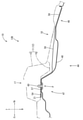
荷室30は、図2に示すように、ボデーパネル11に取り付けられて壁面を形成するトリム(内装材)31,32,40と、底面を形成するデッキボード33と、によって囲まれることで形成されている。すなわち、荷室30は、前方の壁面を形成するフロントトリム31と、左右の壁面を形成するサイドトリム32(左方のサイドトリムを省略する)と、上方の壁面を形成するアッパートリム40と、下方の底面を形成するデッキボード33と、によって囲まれている。
As shown in FIG. 2, the
右方の壁面を形成するサイドトリム32は、その前方端がフロントトリム31の後方端に接続されている。アッパートリム40は、その前方端がフロントトリム31の上端に接続されるとともに、その左右端がサイドトリム32の上端に接続されている。デッキボード33は、フロントトリム31の下端及びサイドトリム32の下端によって仕切られた部分を埋めるように敷設されている。
The front end of the
また、アッパートリム40は、図2ないし図4に示すように、その後端部において、左右端部に配されたクリップ60,60と、クリップ60,60の間に配されたクリップ61,61と、によって荷室30のパネル天井部12に対し室内側から取り付けられている。
Further, as shown in FIGS. 2 to 4, the
さらに、アッパートリム40は、その後端部かつ左右の端部が車両後方へ膨出した膨出部44,44を有する。この膨出部44,44は、パネル天井部12の延出部12B,12Bに倣うように、すなわち、パネル天井部12が延出基端部17から延出端部18まで延出した形状に倣うように膨出している。膨出部44,44は、延出部12B,12Bに対して取り付けられる内装材の一部分であるともいえる。また、膨出部44,44の上方(室外側)には、膨出部44,44を補強する平面視長手状の2つの補強部材50,50が付設されている。
Further, the
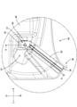
以下、図3及び図4を参照しつつ、膨出部44,44と補強部材50との組付態様(図3では左側の膨出部44を示している)について説明する。補強部材50は、膨出部44が膨出する基端付近の膨出基端部47から、膨出した先端付近の膨出先端部48までの位置に対応するように延在する金属の板状体である。補強部材50の後側の端部58は、図4に示すように、膨出先端部48に室外側から接着されている。
Hereinafter, the assembling mode of the bulging
また、補強部材50は、膨出部44及び延出部12Bに上下方向から挟まれるようにして重なっている。そして、膨出基端部47及び補強部材50の前側の端部57は、延出基端部17において、パネル天井部12に対して1つのクリップ60によって共締めにより取り付けられている。尚、このクリップ60が取り付けられた箇所を取付箇所Pとする。
Further, the reinforcing
補強部材50の前側の端部57の先端部分である先端部54には、その上下面を覆うように接着された断面視U字状の付勢部材20が配されている。付勢部材20は、その素材として不織布を採用することができ、一定の厚みを有する。従って、インナパネル16と先端部54との間に付勢部材20が介在することで、先端部54がインナパネル16から離れる方向(下方)へ押し下げられている。言い換えれば、取付箇所Pよりも車両前方の位置となる、パネル天井部12の面内内側において、補強部材50を室内側に付勢する付勢部材20が配されているともいえる。
A U-shaped urging
続いて、本実施形態の効果について説明する。本実施形態では、上述の通り、乗物1の荷室30のパネル天井部(天井)12に対する内装材40の取付構造を例示した。この取付構造においては、荷室30の天井12は、その周端部において部分的に外側に延出した延出部12Bを備えて構成され、内装材40には、内装材40を補強する補強部材50が付設されている。内装材40及び補強部材50は、少なくとも延出部12Bの延出基端部17において、荷室30の天井12に対して重ねて取り付けられ、荷室30の天井12に対する内装材40及び補強部材50の取付箇所Pよりも、荷室30の天井12の面内内側において、補強部材50を室内側に付勢する付勢部材20が配されている。
Subsequently, the effect of this embodiment will be described. In the present embodiment, as described above, the mounting structure of the
従って、荷室30の天井12に対する内装材40及び補強部材50の取付箇所Pよりも、荷室30の天井12の面内内側に配された付勢部材20によって、補強部材50の一方の端部(先端部)57が室内側に付勢されることとなる。すると、当該取付箇所Pが支点となって、てこの原理が働き、当該取付箇所Pよりも荷室30の天井12の面内外側に位置する補強部材50の他方の端部(後方の端部)58が室外側へ持ち上げられる。その結果、補強部材50に補強された内装材40が、室外側へ持ち上がることとなる。従って、本実施形態のように延出部12Bに取付けられる内装材40の膨出部44が存在する場合であっても、自重によって垂れ下がることが防止されている。
Therefore, one end of the reinforcing
また、本実施形態では、補強部材50は、内装材40の室外側に配されている。従って、天井12と内装材40の間に補強部材50を隠すことができる。すると、乗員が荷室30に荷物を出し入れする際に、補強部材50に荷物が引っ掛かって、内装材40が剥がれたり垂れ下がったりすることを防ぐことができる。また、補強部材50が室内側にむき出しにならないので、荷室30の意匠性が向上されている。
Further, in the present embodiment, the reinforcing
また、本実施形態では、内装材40は、荷室30のアッパートリム40である。従って、アウタパネル15がインナパネル16よりも比較的大きくオーバーラップした部分(延出端部)18であっても、内装材40の垂れ下がりが防止されている。
Further, in the present embodiment, the
次に、本発明の変形例1を図5によって説明する。インナパネル16において、補強部材50の先端部54に対応する位置には、その下面から接着された付勢部材21が配されている。付勢部材21は、その素材として不織布を採用することができ、一定の厚みを有する。従って、インナパネル16と先端部54の間に付勢部材21が介在することで、先端部54がインナパネル16から離れる方向(下方)へ押し下げられている。
Next, a
<実施形態2>
次に、本発明の実施形態2を図6によって説明する。本実施形態では、実施形態1とはアッパートリム及び補強部材の配置が異なる乗物の荷室天井に対する内装材の取付構造を例示する。なお、本実施形態では、上記実施形態と同じ部位には、同一の符号を用い、構造、作用及び効果について重複する説明は省略する。
<
Next,
アッパートリム240は、その後端部が車両後方へ膨出した膨出部244を有する。膨出部244の下方(室内側)には、膨出部244を補強する平面視長手状の補強部材250が付設されている。補強部材250は、膨出部244が膨出する基端付近の膨出基端部247から、膨出した先端付近の膨出先端部248までの位置に対応するように延在する金属の板状体である。補強部材250の後方の端部258は、膨出先端部248に室内側から接着されている。
The
膨出基端部247及び補強部材250の前側の端部257は、延出基端部17において、車両本体210のパネル天井部12に対して1つのクリップ60によって共締めにより取り付けられている。尚、このクリップ60が取り付けられた箇所を取付箇所Pとする。
The bulging
補強部材250の前側の端部257の先端部分である先端部254には、その上下面を覆うように接着された断面視U字状の付勢部材20が配されている。付勢部材20は、その素材として不織布を採用することができ、一定の厚みを有する。従って、膨出基端部247と先端部254との間に付勢部材20が介在することで、先端部254が膨出基端部247から離れる方向(下方)へ押し下げられている。言い換えれば、取付箇所Pよりも車両前方の位置となる、パネル天井部12の面内内側において、補強部材250を室内側に付勢する付勢部材20が配されているともいえる。
A U-shaped urging
<他の実施形態>
本発明は上記記述及び図面によって説明した実施形態に限定されるものではなく、例えば次のような実施形態も本発明の技術的範囲に含まれ、さらに、下記以外にも要旨を逸脱しない範囲内で種々変更して実施することができる。
<Other embodiments>
The present invention is not limited to the embodiments described in the above description and drawings, and for example, the following embodiments are also included in the technical scope of the present invention, and further, within the scope not deviating from the gist other than the following. It can be changed in various ways.
(1)上記実施形態以外にも、付勢部材の構成は適宜変更可能である。上記実施形態では、付勢部材は、一定の厚みを有する不織布としたが、これに限られない。例えば、付勢部材は、織布、発泡材、バネ等であってもよい。 (1) In addition to the above embodiment, the configuration of the urging member can be changed as appropriate. In the above embodiment, the urging member is a nonwoven fabric having a certain thickness, but the urging member is not limited to this. For example, the urging member may be a woven fabric, a foam material, a spring, or the like.
(2)上記実施形態以外にも、内装材が取り付けられる天井は適宜変更可能である。上記実施形態では、図1に示すように、内装材が取り付けられる天井は、パネル天井部12としたが、これに限られない。例えば、内装材が取り付けられる天井は、ドア天井部112であってもよい。この場合、ドア天井部112の延出部113Bに対し、補強部材及び内装材を室内側から取り付けて、本願発明の取付構造を適用してもよい。
(2) In addition to the above embodiment, the ceiling to which the interior material is attached can be changed as appropriate. In the above embodiment, as shown in FIG. 1, the ceiling to which the interior material is attached is the
(3)上記各実施形態で例示した乗物の荷室天井に対する内装材の取付構造は、車両用に提供されるもの限られず、種々の乗物において提供されるものであってもよい。例えば、地上の乗物としての列車や遊戯用車両、飛行用乗物としての飛行機やヘリコプター、海上や海中用乗物としての船舶や潜水艇などの乗物についても上記乗物の荷室天井に対する内装材の取付構造を適用することができる。 (3) The attachment structure of the interior material to the luggage compartment ceiling of the vehicle exemplified in each of the above embodiments is not limited to that provided for the vehicle, and may be provided in various vehicles. For example, for vehicles such as trains and amusement vehicles as ground vehicles, airplanes and helicopters as flight vehicles, ships and submersibles as marine and underwater vehicles, the mounting structure of interior materials to the ceiling of the luggage compartment of the above vehicles. Can be applied.
1…車両(乗物)、2…ダンパー、10,210…車両本体、11,111…ボデーパネル、12…パネル天井部、12B…延出部、15…アウタパネル、16…インナパネル、17…延出基端部、18…延出端部、20,21…付勢部材、30…荷室、40,240…アッパートリム(内装材)、44,244…膨出部、47,247…膨出基端部、48,248…膨出先端部、50,250…補強部材、54,254…先端部、57,257…前方の端部、58,258…後方の端部、60,61…クリップ、100…ラゲージドア、112…ドア天井部、P…取付箇所 1 ... Vehicle (vehicle), 2 ... Damper, 10,210 ... Vehicle body, 11,111 ... Body panel, 12 ... Panel ceiling, 12B ... Extension, 15 ... Outer panel, 16 ... Inner panel, 17 ... Extension Base end, 18 ... extension end, 20, 21 ... urging member, 30 ... luggage compartment, 40, 240 ... upper trim (interior material), 44, 244 ... bulge, 47, 247 ... bulge base End, 48,248 ... bulging tip, 50,250 ... reinforcing member, 54,254 ... tip, 57,257 ... front end, 58,258 ... rear end, 60,61 ... clip, 100 ... Luggage door, 112 ... Door ceiling, P ... Mounting location
Claims (3)
前記内装材を前記荷室天井に取り付ける取付部材を備え、
前記荷室天井は、その周端部において部分的に外側に延出した延出部を備えて構成され、
前記内装材には、前記内装材を補強する補強部材が付設され、
前記内装材及び前記補強部材は、少なくとも前記延出部の延出基端部において、当該内装材及び当該補強部材が部分的に重ねられた取付箇所に前記取付部材が室内側から取り付けられることで、前記荷室天井に対して重ねて取り付けられ、
前記荷室天井に対する前記内装材及び前記補強部材の前記取付箇所よりも、前記荷室天井の面内内側において、前記補強部材を室内側に付勢する付勢部材が配されていることを特徴とする乗物の荷室天井に対する内装材の取付構造。 It is a structure for attaching interior materials to the ceiling of the luggage compartment of a vehicle.
A mounting member for attaching the interior material to the luggage compartment ceiling is provided.
The luggage compartment ceiling is configured to include an extension portion that partially extends outward at its peripheral end.
A reinforcing member for reinforcing the interior material is attached to the interior material.
The interior material and the reinforcing member are such that the mounting member is mounted from the indoor side at a mounting location where the interior material and the reinforcing member are partially overlapped at least at the extension base end portion of the extending portion. , Mounted on top of the luggage compartment ceiling,
It is characterized in that an urging member for urging the reinforcing member to the indoor side is arranged inside the surface of the luggage compartment ceiling rather than the interior material and the mounting portion of the reinforcing member with respect to the luggage compartment ceiling. The mounting structure of the interior material to the ceiling of the luggage compartment of the vehicle.
Priority Applications (1)
| Application Number | Priority Date | Filing Date | Title |
|---|---|---|---|
| JP2018082940A JP6996410B2 (en) | 2018-04-24 | 2018-04-24 | Interior material mounting structure on the ceiling of the luggage compartment of a vehicle |
Applications Claiming Priority (1)
| Application Number | Priority Date | Filing Date | Title |
|---|---|---|---|
| JP2018082940A JP6996410B2 (en) | 2018-04-24 | 2018-04-24 | Interior material mounting structure on the ceiling of the luggage compartment of a vehicle |
Publications (2)
| Publication Number | Publication Date |
|---|---|
| JP2019188983A JP2019188983A (en) | 2019-10-31 |
| JP6996410B2 true JP6996410B2 (en) | 2022-01-17 |
Family
ID=68388387
Family Applications (1)
| Application Number | Title | Priority Date | Filing Date |
|---|---|---|---|
| JP2018082940A Active JP6996410B2 (en) | 2018-04-24 | 2018-04-24 | Interior material mounting structure on the ceiling of the luggage compartment of a vehicle |
Country Status (1)
| Country | Link |
|---|---|
| JP (1) | JP6996410B2 (en) |
Citations (2)
| Publication number | Priority date | Publication date | Assignee | Title |
|---|---|---|---|---|
| JP2017024427A (en) | 2013-11-06 | 2017-02-02 | 本田技研工業株式会社 | Inner package structure of cargo chamber in vehicle |
| JP2017128174A (en) | 2016-01-19 | 2017-07-27 | トヨタ紡織株式会社 | Sunroof panel, ceiling module including the same, and ceiling structure |
-
2018
- 2018-04-24 JP JP2018082940A patent/JP6996410B2/en active Active
Patent Citations (2)
| Publication number | Priority date | Publication date | Assignee | Title |
|---|---|---|---|---|
| JP2017024427A (en) | 2013-11-06 | 2017-02-02 | 本田技研工業株式会社 | Inner package structure of cargo chamber in vehicle |
| JP2017128174A (en) | 2016-01-19 | 2017-07-27 | トヨタ紡織株式会社 | Sunroof panel, ceiling module including the same, and ceiling structure |
Also Published As
| Publication number | Publication date |
|---|---|
| JP2019188983A (en) | 2019-10-31 |
Similar Documents
| Publication | Publication Date | Title |
|---|---|---|
| JP5874610B2 (en) | Interior materials for vehicles | |
| JP2009137397A (en) | Vehicle door | |
| JP6996410B2 (en) | Interior material mounting structure on the ceiling of the luggage compartment of a vehicle | |
| JP5151740B2 (en) | Door trim pocket structure | |
| JP2024161129A5 (en) | ||
| JP6772795B2 (en) | Vehicle armrests | |
| JP6423842B2 (en) | Vehicle fender structure | |
| JP6708069B2 (en) | Vehicle hood | |
| JP6459897B2 (en) | Rear structure of the vehicle | |
| JP5233581B2 (en) | Car body rear structure | |
| JP2005324668A (en) | Vehicle accessory storage structure | |
| CN111204289B (en) | Luggage Compartment Structure for Vehicles | |
| JP7074573B2 (en) | Ceiling structure for vehicles | |
| JP6792816B2 (en) | Roof lining mounting structure | |
| JP2020157789A (en) | Vehicle luggage space structure | |
| JPH0214985Y2 (en) | ||
| JPH0539004Y2 (en) | ||
| JPH0732180Y2 (en) | Ventilation structure for automobiles | |
| JP2019182355A (en) | Vehicle door | |
| JPS5921968Y2 (en) | Storage bag on the back of the seat in a vehicle, etc. | |
| JP5913946B2 (en) | Instrument panel assembly structure | |
| JP2021172292A (en) | Hook structure for passenger compartment | |
| JPS6031975Y2 (en) | automotive trim panel | |
| JP6563836B2 (en) | Attachment structure of insect net to vehicle body and method of attaching insect net to vehicle body | |
| JP6590785B2 (en) | Luggage side trim assembly structure |
Legal Events
| Date | Code | Title | Description |
|---|---|---|---|
| A621 | Written request for application examination |
Free format text: JAPANESE INTERMEDIATE CODE: A621 Effective date: 20201110 |
|
| A131 | Notification of reasons for refusal |
Free format text: JAPANESE INTERMEDIATE CODE: A131 Effective date: 20210831 |
|
| A977 | Report on retrieval |
Free format text: JAPANESE INTERMEDIATE CODE: A971007 Effective date: 20210831 |
|
| A521 | Request for written amendment filed |
Free format text: JAPANESE INTERMEDIATE CODE: A523 Effective date: 20211027 |
|
| TRDD | Decision of grant or rejection written | ||
| A01 | Written decision to grant a patent or to grant a registration (utility model) |
Free format text: JAPANESE INTERMEDIATE CODE: A01 Effective date: 20211116 |
|
| A61 | First payment of annual fees (during grant procedure) |
Free format text: JAPANESE INTERMEDIATE CODE: A61 Effective date: 20211129 |
|
| R151 | Written notification of patent or utility model registration |
Ref document number: 6996410 Country of ref document: JP Free format text: JAPANESE INTERMEDIATE CODE: R151 |
|
| R250 | Receipt of annual fees |
Free format text: JAPANESE INTERMEDIATE CODE: R250 |
|
| R250 | Receipt of annual fees |
Free format text: JAPANESE INTERMEDIATE CODE: R250 |