JP6971317B2 - Suspension system group for motorized vehicle, wheel group for motorized vehicle, front end of motorized vehicle and motorized vehicle - Google Patents
Suspension system group for motorized vehicle, wheel group for motorized vehicle, front end of motorized vehicle and motorized vehicle Download PDFInfo
- Publication number
- JP6971317B2 JP6971317B2 JP2019528917A JP2019528917A JP6971317B2 JP 6971317 B2 JP6971317 B2 JP 6971317B2 JP 2019528917 A JP2019528917 A JP 2019528917A JP 2019528917 A JP2019528917 A JP 2019528917A JP 6971317 B2 JP6971317 B2 JP 6971317B2
- Authority
- JP
- Japan
- Prior art keywords
- group
- crank
- motorized vehicle
- suspension device
- shock absorber
- Prior art date
- Legal status (The legal status is an assumption and is not a legal conclusion. Google has not performed a legal analysis and makes no representation as to the accuracy of the status listed.)
- Active
Links
Images


Classifications
-
- B—PERFORMING OPERATIONS; TRANSPORTING
- B62—LAND VEHICLES FOR TRAVELLING OTHERWISE THAN ON RAILS
- B62K—CYCLES; CYCLE FRAMES; CYCLE STEERING DEVICES; RIDER-OPERATED TERMINAL CONTROLS SPECIALLY ADAPTED FOR CYCLES; CYCLE AXLE SUSPENSIONS; CYCLE SIDE-CARS, FORECARS, OR THE LIKE
- B62K5/00—Cycles with handlebars, equipped with three or more main road wheels
- B62K5/02—Tricycles
- B62K5/027—Motorcycles with three wheels
-
- B—PERFORMING OPERATIONS; TRANSPORTING
- B60—VEHICLES IN GENERAL
- B60G—VEHICLE SUSPENSION ARRANGEMENTS
- B60G13/00—Resilient suspensions characterised by arrangement, location or type of vibration dampers
- B60G13/001—Arrangements for attachment of dampers
- B60G13/005—Arrangements for attachment of dampers characterised by the mounting on the axle or suspension arm of the damper unit
-
- B—PERFORMING OPERATIONS; TRANSPORTING
- B60—VEHICLES IN GENERAL
- B60G—VEHICLE SUSPENSION ARRANGEMENTS
- B60G3/00—Resilient suspensions for a single wheel
- B60G3/01—Resilient suspensions for a single wheel the wheel being mounted for sliding movement, e.g. in or on a vertical guide
-
- B—PERFORMING OPERATIONS; TRANSPORTING
- B60—VEHICLES IN GENERAL
- B60G—VEHICLE SUSPENSION ARRANGEMENTS
- B60G3/00—Resilient suspensions for a single wheel
- B60G3/02—Resilient suspensions for a single wheel with a single pivoted arm
- B60G3/04—Resilient suspensions for a single wheel with a single pivoted arm the arm being essentially transverse to the longitudinal axis of the vehicle
-
- B—PERFORMING OPERATIONS; TRANSPORTING
- B60—VEHICLES IN GENERAL
- B60G—VEHICLE SUSPENSION ARRANGEMENTS
- B60G3/00—Resilient suspensions for a single wheel
- B60G3/18—Resilient suspensions for a single wheel with two or more pivoted arms, e.g. parallelogram
- B60G3/20—Resilient suspensions for a single wheel with two or more pivoted arms, e.g. parallelogram all arms being rigid
-
- B—PERFORMING OPERATIONS; TRANSPORTING
- B60—VEHICLES IN GENERAL
- B60G—VEHICLE SUSPENSION ARRANGEMENTS
- B60G7/00—Pivoted suspension arms; Accessories thereof
- B60G7/001—Suspension arms, e.g. constructional features
-
- B—PERFORMING OPERATIONS; TRANSPORTING
- B62—LAND VEHICLES FOR TRAVELLING OTHERWISE THAN ON RAILS
- B62K—CYCLES; CYCLE FRAMES; CYCLE STEERING DEVICES; RIDER-OPERATED TERMINAL CONTROLS SPECIALLY ADAPTED FOR CYCLES; CYCLE AXLE SUSPENSIONS; CYCLE SIDE-CARS, FORECARS, OR THE LIKE
- B62K25/00—Axle suspensions
-
- B—PERFORMING OPERATIONS; TRANSPORTING
- B62—LAND VEHICLES FOR TRAVELLING OTHERWISE THAN ON RAILS
- B62K—CYCLES; CYCLE FRAMES; CYCLE STEERING DEVICES; RIDER-OPERATED TERMINAL CONTROLS SPECIALLY ADAPTED FOR CYCLES; CYCLE AXLE SUSPENSIONS; CYCLE SIDE-CARS, FORECARS, OR THE LIKE
- B62K5/00—Cycles with handlebars, equipped with three or more main road wheels
- B62K5/08—Cycles with handlebars, equipped with three or more main road wheels with steering devices acting on two or more wheels
-
- B—PERFORMING OPERATIONS; TRANSPORTING
- B62—LAND VEHICLES FOR TRAVELLING OTHERWISE THAN ON RAILS
- B62K—CYCLES; CYCLE FRAMES; CYCLE STEERING DEVICES; RIDER-OPERATED TERMINAL CONTROLS SPECIALLY ADAPTED FOR CYCLES; CYCLE AXLE SUSPENSIONS; CYCLE SIDE-CARS, FORECARS, OR THE LIKE
- B62K5/00—Cycles with handlebars, equipped with three or more main road wheels
- B62K5/10—Cycles with handlebars, equipped with three or more main road wheels with means for inwardly inclining the vehicle body on bends
-
- B—PERFORMING OPERATIONS; TRANSPORTING
- B60—VEHICLES IN GENERAL
- B60G—VEHICLE SUSPENSION ARRANGEMENTS
- B60G2204/00—Indexing codes related to suspensions per se or to auxiliary parts
- B60G2204/10—Mounting of suspension elements
- B60G2204/30—In-wheel mountings
-
- B—PERFORMING OPERATIONS; TRANSPORTING
- B60—VEHICLES IN GENERAL
- B60G—VEHICLE SUSPENSION ARRANGEMENTS
- B60G2300/00—Indexing codes relating to the type of vehicle
- B60G2300/12—Cycles; Motorcycles
- B60G2300/122—Trikes
-
- B—PERFORMING OPERATIONS; TRANSPORTING
- B60—VEHICLES IN GENERAL
- B60G—VEHICLE SUSPENSION ARRANGEMENTS
- B60G2300/00—Indexing codes relating to the type of vehicle
- B60G2300/45—Rolling frame vehicles
-
- B—PERFORMING OPERATIONS; TRANSPORTING
- B62—LAND VEHICLES FOR TRAVELLING OTHERWISE THAN ON RAILS
- B62K—CYCLES; CYCLE FRAMES; CYCLE STEERING DEVICES; RIDER-OPERATED TERMINAL CONTROLS SPECIALLY ADAPTED FOR CYCLES; CYCLE AXLE SUSPENSIONS; CYCLE SIDE-CARS, FORECARS, OR THE LIKE
- B62K5/00—Cycles with handlebars, equipped with three or more main road wheels
- B62K2005/001—Suspension details for cycles with three or more main road wheels
Description
本発明は、原動機付き車両(例えば、二輪または三輪の原動機付き車両)の車輪の懸架装置群に関する。 The present invention relates to a group of wheel suspensions for a motorized vehicle (eg, a two-wheeled or three-wheeled motorized vehicle).
さらに、本発明は、原動機付き車両の前端部とその原動機付き車両の両方で、懸架装置群と一体化された原動機付き車両の車輪群に関する。 Further, the present invention relates to a wheel group of a motorized vehicle integrated with a suspension system group at both the front end portion of the motorized vehicle and the motorized vehicle thereof.
原動機付き車両の車輪に適用される様々な懸架装置解決策が知られている。懸架装置は、車輪支持のための所定の剛性を保証しなければならず、同時に、特に三輪の原動機付き車両で、車両の動的な挙動を改善するために大きさおよび重量の削減を提供しなければならない。三輪の原動機付き車両は、後部に駆動輪を、前部に操舵および傾斜する種類の二つの車輪を備える。後輪は、駆動トルクを提供するという目的を有する一方、互いに実質的に平行な前輪は、車両の進む方向を決める。 Various suspension solutions are known that apply to the wheels of motorized vehicles. Suspension devices must ensure a given stiffness for wheel support, while at the same time providing size and weight reduction to improve the dynamic behavior of the vehicle, especially in three-wheeled motorized vehicles. There must be. A three-wheeled motor vehicle has a drive wheel at the rear and two wheels of the type steered and tilted at the front. The rear wheels have the purpose of providing drive torque, while the front wheels, which are substantially parallel to each other, determine the direction in which the vehicle travels.
前輪は、例えば、関節接合された四角形の介在によって、同期的かつ対称的にロールおよび操舵することを確保する運動学的システムを介して互いに運動学的に連結されている。 The front wheels are kinematically connected to each other via a kinematic system that ensures synchronous and symmetrical rolling and steering, for example, through the intervention of articulated squares.
四角形構造の懸架装置群は、本出願人の名前で知られており、カバーの内側に一体化されたショックアブソーバ(緩衝装置)群を備えられた車輪ガイドを備えている。車輪ガイドは、クランクおよびガイド棒を介して支持アームに連結されており、クランクは、車輪ガイドの端部と支持アームの端部でヒンジ連結され、ガイド棒は、カバーの内側に摺動自在に連結されたショックアブソーバ群の頭頂部に合わされている。ガイド棒の移動は、カバーに作られたスロットによって定められる。ショックアブソーバ群の頭頂部は、シリンダ−ピストン連結を形成し、ショックアブソーバ群の摺動に対する軸方向のガイドとして作用する。 The rectangular suspension system group, known in the name of the applicant, is equipped with a wheel guide equipped with a shock absorber (buffer device) group integrated inside the cover. The wheel guide is connected to the support arm via a crank and a guide rod, the crank is hinged at the end of the wheel guide and the end of the support arm, and the guide rod is slidable inside the cover. It is fitted to the crown of a group of connected shock absorbers. The movement of the guide rod is determined by the slot made in the cover. The crown of the shock absorber group forms a cylinder-piston connection and acts as an axial guide to the sliding of the shock absorber group.
前述の解決策は、機能的に有効であるが、いくつかの欠点を有する。頭頂部は、スロットを通じて外側に開口しており、したがって、シリンダ−ピストン連結は、土砂の堆積にさらされ、当該態様は、シール性および一般的な機能の劣化を生じさせる。 While the aforementioned solution is functionally effective, it has some drawbacks. The crown is open outward through the slot and therefore the cylinder-piston connection is exposed to sediment deposits, which aspect results in deterioration of sealing and general function.
したがって、前述の欠点を解決する必要性が感じられる。 Therefore, there is a need to solve the above-mentioned drawbacks.
懸架装置群の性能を改善する必要性はまた、ショックアブソーバの車輪ガイドに固定された車輪の軌跡のよりよい制御、懸架装置群のより高い強度、および製造費用に関して感じられる。 The need to improve the performance of the suspension system is also felt with respect to better control of the wheel trajectories fixed to the wheel guides of the shock absorber, higher strength of the suspension system, and manufacturing costs.
したがって、本発明の目的は、従来技術による解決策に対して動的な反応および製造費用が改善された原動機付き車両の懸架装置群を提供することである。 Therefore, it is an object of the present invention to provide a group of suspension devices for a motorized vehicle with improved dynamic reaction and manufacturing cost to a solution according to the prior art.
本発明の別の目的は、同じ目的を実現する懸架装置群を備える車輪群を提供することである。 Another object of the present invention is to provide a wheel group provided with a suspension device group that achieves the same object.
また、本発明の目的は、同じ目的を実現する原動機付き車両の前端部およびその原動機付き車両を提供することである。 It is also an object of the present invention to provide a front end of a motorized vehicle and a motorized vehicle thereof that achieves the same object.
これらの、およびその他の目的は、請求項1に記載している原動機付き車両用の懸架装置群によって達成される。 These and other purposes are achieved by the suspension set for the motorized vehicle according to claim 1.
本発明は、添付図面に関して、非限定的な例の方法で作られた、後述する実施形態の記載とともに以下で説明されている。 The present invention is described below with respect to the accompanying drawings, along with a description of embodiments described below, made in a non-limiting example way.
以下に記載された実施形態間で共通の部材または部材の部品は、同一の符号で示されている。 Members or parts of members that are common among the embodiments described below are designated by the same reference numerals.
上述の図に関して、本発明による原動機付き車両の全体概略図は、まとめて100で示されている。 With respect to the above figure, the overall schematic of the motorized vehicle according to the present invention is collectively shown by 100.
本発明において、用語「原動機付き車両(motor vehicle)」は、広義で考えられるものであり、少なくとも三つの車輪(すなわち、以下でより詳細に記載されているような二つの前輪102、102a、および少なくとも一つの後輪103)を有する任意のモータサイクルを含む。したがって、いわゆる四輪車は同様に原動機付き車両の定義に含まれ、前端部に二つの車輪および後車軸に二つの車輪を有する。
In the present invention, the term "motor vehicle" is considered in a broad sense, with at least three wheels (ie, two
原動機付き車両100は、少なくとも二つの前輪102、102aを支持する前端部108から、一つ以上の後輪103を支持する後車軸109へと延在するシャーシ101を備える。
The
たとえ示されていない場合でも、進行方向を向いて乗車している運転手に対して、図2aにて概略的に示されている右側前輪102、および左側前輪102aが、示されている。車輪102、102aは、運転手の観測点から見て、原動機付き車両の中心線平面M−Mの左側と右側に配置されている。
Even if not shown, the right
本発明に関して、原動機付き車両のシャーシ101は、任意の形状と大きさであってよく、また、例えば、ラティス(格子)タイプ、ボックス(箱)タイプ、シングルクレードルまたはダブルクレードルのものなどであってもよい。
With respect to the present invention, the
特に、原動機付き車両100の前端部108は、前端フレーム116および一対の前輪102、102aを備え、一対の前輪102、102aは、ロールする関節接合された四角形120によって前端シャーシ116に運動学的に連結されている。ロールする関節接合された四角形120によって、前輪102、102aはロール、つまり、地面に垂直な方向に対して傾斜できる。
In particular, the
前端部108は、それぞれの前輪102、102aで、懸架装置群10を備える。
The
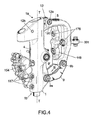
図3および図4でより詳細に示されているように、懸架装置群10は、車輪ガイド1を備え、これは長手方向軸T−Tに沿って延在している。車輪ガイド1は、長手方向軸T−Tに直角な回転軸R−Rで車輪102、102aの回転ピン3に連結するための車輪取り付け部2を提供している。
As shown in more detail in FIGS. 3 and 4, the
特に、車輪ガイド1は、互いに反対側にある第1の端部1aと第2の端部1bとの間に延在している。
In particular, the wheel guide 1 extends between the
懸架装置群10は、基礎部7aから、基礎部7aに対して反対側にある頭頂部7bへと延在するショックアブソーバ群7をさらに備える。基礎部および頭頂部は、互いに移動可能であり、車輪ガイド1と支持アーム8と第1のクランク9とクランク12(以下でより詳細に記載する)の中の少なくとも二つの部材に連結されている。
The
例えば、ショックアブソーバ群7は、弾性手段72およびダンパ71を備える。
For example, the
懸架装置群10は、第1のクランク9と第2のクランク12それぞれを用いて車輪ガイド1に機能的に連結された支持アーム8を備える。
The
第1のクランク9は、第2の端部1bで(例えば、第1のヒンジ9aを介して)車輪ガイド1に、および(例えば、第2のヒンジ9bを介して)支持アーム8に枢動可能に連結されている。
The
第2のクランク12は、第1の端部1aで車輪ガイド1および支持アーム8に枢動可能に連結されている。
The
例えば、第2のクランク12は、第1の端部1aで、支持アーム8に配置された第3のヒンジ12aを介して、および車輪ガイド1に配置された第4のヒンジ12bを介して枢動可能に連結されている。
For example, the
一実施形態によると、第1のクランク9は、第2の端部1bで、車輪ガイド1に配置された第1のヒンジ9a、および支持アーム8に配置された第2のヒンジ9bを介して枢動可能に連結されている。
According to one embodiment, the
車輪ガイド1、支持アーム8、並びに第1のクランク9および第2のクランク12は、共同で関節接合された懸架四角形を形成している。それぞれの車輪は、車輪自体の関節接合された懸架四角形に枢動可能に連結されている。懸架四角形は、ロールする関節接合された四角形120によって互いに連結されている。そして、ロールする関節接合された四角形120は、懸架四角形を原動機付き車両のシャーシに連結している。好適には、車輪ガイド1と支持アーム8と第1のクランク9と第2のクランク12の中から選択された部材の少なくとも二つの間で、ショックアブソーバ群7は、懸架四角形の運動が変化したときにショックアブソーバ群7がその伸びを変化させるように、相互に連結されている。
The wheel guide 1, the
一般的に、そのようなショックアブソーバ群は、弾性手段72(典型的だが非排他的にはコイルバネまたはトーションバー)およびダンパ71を備える。弾性手段72およびダンパ71は、車輪ガイド1と支持アーム8と第1のクランク9と第2のクランク12の中から選択された同じ二つの部材の間に配置される必要はない。したがって、弾性手段72およびダンパ71は、ともに一体化されている場合、懸架四角形の同じ部材に連結するが、一方、分離している場合、四角形の同じ部材に連結してもよいし、懸架四角形の部材の異なる部品に連結してもよい。
Generally, such shock absorbers include elastic means 72 (typically but non-exclusively coil springs or torsion bars) and dampers 71. The elastic means 72 and the damper 71 need not be arranged between the same two members selected from the wheel guide 1, the
一実施形態によると、ショックアブソーバ群は、第1のクランク9と第2のクランク12との間に設けられている。
According to one embodiment, the shock absorber group is provided between the first crank 9 and the
一実施形態によると、ショックアブソーバ群7は、第1のクランク9と支持アーム8との間に設けられている。
According to one embodiment, the
一実施形態によると、ショックアブソーバ群7は、第1のクランク9と車輪ガイド1との間に設けられている。
According to one embodiment, the
一実施形態によると、ショックアブソーバ群7は、第2のクランク12と支持アーム8との間に設けられている。
According to one embodiment, the
一実施形態によると、ショックアブソーバ群7は、第2のクランク12と車輪ガイド1との間に設けられている。
According to one embodiment, the
一実施形態によると、ショックアブソーバ群7は、支持アーム8と車輪ガイド1との間に設けられている。
According to one embodiment, the
一実施形態によると、弾性手段72は、車輪102、車輪102aで増加した負荷によって縮むように配置されている。当該状態は、図1aで概略的に示されており、ここでは、記載されたように圧縮された弾性手段72の様々な想定される傾き/配置が示されている。
According to one embodiment, the elastic means 72 is arranged so as to contract due to the increased load on the
さらなる想定される実施形態によると、弾性手段72は、車輪102、車輪102aで増加した負荷によって伸びるように配置されている。当該状態は、図1bで概略的に示されており、ここでは、記載されたように伸長された弾性手段72の様々な想定される傾き/配置が示されている。
According to a further envisioned embodiment, the elastic means 72 is arranged to stretch due to the increased load on the
一実施形態によると、懸架四角形10は、車輪102、車輪102aのリム184によって形成される容積180(すなわち、径方向に、リム184の内側にある空間)内に含まれる。ショックアブソーバ群7は、軸方向に容積184の外側に少なくとも部分的に配置されてもよい。好ましくは、ショックアブソーバ群7は、当該構成で、容積180に対して少なくとも部分的にカンチレバー(片持ち)に又は外側に配置されている。
According to one embodiment, the
例えば、そのような少なくとも部分的なカンチレバー構成では、ショックアブソーバは、好ましくは第1のクランク9と第2のクランク12に対して回転するように、これらのクランクに二重にヒンジ連結されている。つまり、当該構成では、ショックアブソーバは、フローティングアンカーを有する。 For example, in such at least partial cantilever configurations, the shock absorbers are doubly hinged to these cranks so that they rotate, preferably with respect to the first crank 9 and the second crank 12. .. That is, in this configuration, the shock absorber has a floating anchor.
好ましくは、ショックアブソーバ7は、車輪の内側から中心線平面M−Mへと面して、容積180に対して完全に外側に、またはカンチレバーに配置されている。
Preferably, the
ショックアブソーバを当該位置にすることで、車輪のスタブアクスルの寸法を小さくすることができ、したがって、スタブアクスルが小さくなると材料および処理が削減されるため、関連費用も減らすことができる。また、懸架装置群を当該配置にすると、より細いトラック幅を備える車両の構造にすることができる。 By placing the shock absorber in that position, the dimensions of the wheel stub axle can be reduced, and therefore smaller stub axles reduce material and processing, thus reducing associated costs. Further, by arranging the suspension device group in this arrangement, it is possible to form a vehicle structure having a narrower truck width.
さらに、ショックアブソーバ7は、端部7a、端部7bで単純な結合を有し、その外側位置では、その油圧本体およびバネがスタブアクスルの内側での通過寸法を抑制しないため、その大きさに対して操縦性の大きなマージンが得られる。さらに、容積180の外側に位置することで、単一の弾性係数を備えるバネを使用できる高い幾何学的漸進性を有する挙動を得ることができる。
Further, the
弾性手段72は典型的には、一定のまたは可変のピッチによってコイルが巻かれたコイルバネを備える。 The elastic means 72 typically comprises a coil spring in which the coil is wound by a constant or variable pitch.
例えば、弾性手段は、既知の方法で、ショックアブソーバ7と同軸上に配置されたバネである。
For example, the elastic means is a spring arranged coaxially with the
弾性手段72は、ショックアブソーバ7に対して直列に、または並列に取り付けられてもよい。
The elastic means 72 may be attached in series or in parallel with the
一実施形態によると、弾性手段72は、ショックアブソーバ7に並列に配置されている。
According to one embodiment, the elastic means 72 is arranged in parallel with the
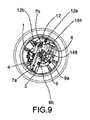
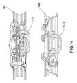
想定されるさらなる実施形態によると(図12〜図17)、第1のクランク9の第1のヒンジ9aおよび第2のヒンジ9bは、第1のクランク9が弾性手段72の機能を実行するトーションバーとして振る舞うことができるように、固定され、または連結している。さらに、好ましくは、当該構成で、ショックアブソーバ7は、ダンパ71のみを備える。
According to a further supposed embodiment (FIGS. 12-17), the
また、第2のクランク12が弾性手段の機能を提供するトーションバーとして振る舞うことができるように、固定され、または連結している、第2のクランク12の第3のヒンジ12aおよび第4のヒンジ12bを設けることも可能である。さらに、好ましくは、そのような構成で、ショックアブソーバ7は、ダンパ71のみを備える。
Also, a
トーションバーとして作用する第1のクランク9と第2のクランク12の使用が交互に発生し、または同時に起きてもよい。つまり、(第1のクランクまたは第2のクランクとして)単一のトーションバーを提供することができ、または両方のクランクがトーションバーとして作用してもよい。 The use of the first crank 9 and the second crank 12 acting as torsion bars may occur alternately or at the same time. That is, a single torsion bar can be provided (as a first crank or a second crank), or both cranks may act as torsion bars.
トーションバーの使用によって、ベアリングであろうとブッシュであろうと、費用に関してかなり有利に、ロトイダルなトルクを除去することができる。 The use of torsion bars, whether bearings or bushes, can eliminate rotational torque in a significant cost advantage.
その上、伝統的ならせんバネを除去することで、特にカバー4に含まれていた場合、カバーの大きさそのものが小さくなるため、および/またはショックアブソーバの本体が大きくなり、懸架装置の油圧部品の挙動(すなわち、ダンピング)を改善することができるため、全体寸法は、かなり改善される。 Moreover, by removing the traditional spiral spring, the size of the cover itself becomes smaller and / or the body of the shock absorber becomes larger, especially if included in the cover 4, and the hydraulic components of the suspension device. The overall dimensions are significantly improved because the behavior of the (ie, damping) can be improved.
さらに、トーションバーは、支持アーム8とカバー4との間またはショックアブソーバ7の頭頂部7bとの間で固定され、回転を導くために通常は使用されるボールベアリングの遊びは、認識されない。
Further, the torsion bar is fixed between the
明らかに、想定される実施形態によると、車輪ガイド1はさらに、管状カバー4(すなわち、中空管の一部)を備え、管状カバー4は、収容空間5(以後、空間5)を定めている。 Obviously, according to the envisioned embodiment, the wheel guide 1 further comprises a tubular cover 4 (ie, part of a hollow tube), which defines a containment space 5 (hereafter, space 5). There is.
管状カバー4は、図3の断面または図5で再度示されているように、第1の端部1aで、スロット6を備える。スロット6は、長手方向軸T−Tに沿った少なくとも一つの区画にわたって延在している。
The tubular cover 4 comprises a slot 6 at the
カバー4は、空間5にショックアブソーバ群7を含むように形成されている(図3参照)。ショックアブソーバ群7は、バネ72に機能的に連結されたダンパ71を備え、両方とも空間5に収容されている。
The cover 4 is formed so as to include the
代替的な実施形態では、空間5は、ダンパ71のみを収容している一方、ダンパ71と機能的に連結されたバネ72は、外側に配置されている。
In an alternative embodiment, the space 5 houses only the damper 71, while the
特に、互いに連結されたダンパ71およびバネ72は、カバー4へのねじ結合によって取り付けられた固定基礎部7a、および固定部7aとは反対側に可動性の頭頂部7bを形成している。可動頭頂部7bは、長手方向軸T−Tにカバー4の空間5内を摺動するように調整されている。
In particular, the damper 71 and the
反対側では、第1の端部1aで、支持アーム8は、支持アーム8から延び、かつショックアブソーバ群7の可動頭頂部7bと合わされたガイド棒11を備える。ガイド棒11は、スロット6内を動き、これは、車輪102、車輪102aによって伝達されたショックアブソーバ群7の揺動運動にしたがった、その移動を定めている。
On the opposite side, at the
図4および図5により詳細に示されているように、ショックアブソーバ群10の伸長構成では、ガイド棒11は、第1の端部1aにある。ショックアブソーバ群7の圧縮段階(図5参照)では、ガイド棒11は、以下で詳細に記載するように、第2の端部1bへ向かって動く。
As shown in detail by FIGS. 4 and 5, in the extended configuration of the
第2のクランク12は、長手方向軸T−Tと実質的に同軸上にある摺動方向に沿って、管状カバー4に沿った可動性頭頂部7bの移動を誘導している。
The
第2のクランク12は、駆動機能を有する。つまり、ショックアブソーバ群7が管状カバーと同軸上に(すなわち、懸架軸を表す長手方向軸T−Tと同軸上に)動くことができる。
The
このようにして、四角形懸架装置の構成は、ショックアブソーバの車輪ガイドに固定された車輪の軌跡のより良い制御、および高い強度、したがって信頼性を確保している。 In this way, the configuration of the square suspension system ensures better control of the wheel trajectory fixed to the wheel guides of the shock absorber, and high strength and thus reliability.
機能的には、(下側に配置された)第1のクランク9は、特に横方向への支持として作用し、一方、(上側に配置された)第2のクランク12は、車輪ガイド1で放たれた制動力への反応および軌跡のガイドとして作用している。 Functionally, the first crank 9 (located on the lower side) acts specifically as a lateral support, while the second crank 12 (located on the upper side) is on the wheel guide 1. It acts as a guide to the response to the released braking force and the trajectory.
特に、第2のクランク12は、回転の瞬間中心が実質的に無限へと近づくような懸架四角形の構成を形成する第1のクランク9に対する寸法比を有し、または、別の構成では(図3および図3Aに概略的に示されているように)、回転の瞬間中心CRは、支持アーム8の外側から有限点に収束している。
In particular, the
特に、回転の瞬間中心CRは、第1のクランク9の第1のヒンジ9aおよび第2のヒンジ9bを通る第1の直線R1と、第2のクランク12の第3のヒンジ12aおよび第4のヒンジ12bを通る第2の線R2とによって定められている。図3Aは、図3に示されている線R1と線R2の交点、すなわち、懸架装置の回転の瞬間中心CRを示している。
In particular, the instantaneous center of rotation CR is the first straight line R1 passing through the
建設的に、好ましい実施形態によると、図4に示されているように、第2のクランク12は、支持アーム8と車輪ガイド1の取り付けヒンジ12a、12bに対応する端部を通過する孔を設けられた平らに形成された部材である。少なくとも一つのベアリングまたはブッシュが通過孔に挿入され、そこにそれぞれピン12c(図5参照)、ピン12d(図3参照)が付けられている。
Constructively, according to a preferred embodiment, as shown in FIG. 4, the
第3のヒンジ12aは、ブランチ8aとして延在している、支持アーム8に形成された取り付け部を備える。特に、取り付け部8aは、反対側で互いに向かい合う取り付け壁8bを備える「U」字形状を有する。したがって、第2のクランク12の端部は、取り付け壁8bの間に含まれ、関連するピン12cは、側壁8bによって機能的に支持されている。
The
その他の建設的な態様では、第1のクランク9は、互いに反対側にある第1のヒンジ9aと第2のヒンジ9bで支持アーム8および車輪ガイド1と連結している、互いに平行な二つの異なる部材9、9’で構成されている。
In another constructive aspect, the
好ましくは、車輪に対応する制動手段154、155(例えば、ディスクブレーキ155用のキャリパ154)は、それぞれの車輪ガイド1に固定されている。本発明において、制動手段154、155は、任意の類いのものでよく、好ましくは、制動手段154、155は、それぞれの車輪102、102aのリム184によって範囲を定められた容積180内に入るような配置および大きさである(図3参照)。
Preferably, the braking means 154, 155 (eg,
車輪ガイド1は、カバー4に形成された特別な小孔157を備え(図4参照)、ブレーキキャリパ154を車輪ガイド1に固定できる。
The wheel guide 1 includes a special
上述された懸架装置群10は、上記されたように図2aの三輪の原動機付き車両100の前端部108のそれぞれの車輪群102、102aに適用されている。
As described above, the
特に、懸架装置群10は全体的に、それぞれの車輪102、102aのリム184によって範囲を定められた容積180内に含まれる(図3参照)。前輪102および前輪102aの懸架装置群10は、各車輪の内側で互いに面している(図2参照)。つまり、懸架装置群10は、原動機付き車両の中心線平面M−Mに向かって回転され、スタブアクスルと関連付けられた関連構成部品は、外部の観察者からは直接は見えない。
In particular, the
図5に示されているように、支持アーム8は、支持垂直物148、支持垂直物148aを備える。
As shown in FIG. 5, the
支持垂直物148、148aは、支持アーム8の内側で一体化され、第1の端部1aと第2の端部1bとの間に延在している。支持垂直物148、148aは、関節接合された四角形120のブランチを形成し、各ステアリングヒンジ176によって支持アーム8と結合している。ステアリングヒンジ176は、互いに平行な、車輪102、102aの各ステアリング軸S−Sを定めている。
The support
関節接合された四角形120はさらに、上側クロスメンバ124および下側クロスメンバ125を備える。クロスメンバ124とクロスメンバ125の対は、中央ヒンジ128で前端シャーシ116とヒンジ連結されている(図2参照)。さらに、クロスメンバ124およびクロスメンバ125は、対応するロールヒンジ178を介して対応する端部に連結されている。
The articulated
懸架装置群10の関節接合された懸架四角形は、各支持垂直物148、148aの軸を中心に回転することで、原動機付き車両を操舵できる。関節接合された懸架四角形は、(単一の、または関節接合された)棒300を通じて回転するように配置されており、棒300は、好ましくは球状ヒンジ301で支持アーム8とヒンジ連結されている。棒300は、ステアリングを動作させるように原動機付き車両のステアリングに機能的に連結されている。原動機付き車両のロールはしたがって、ロールする四角形120によって決定され、一方、操舵は、支持垂直物148、148aの軸(ステアリングヒンジ176とも呼ばれる)を中心とする、ロールする四角形120に対する懸架四角形の回転によってすることができる。
The articulated suspension quadrangle of the
上記内容から分かるように、本発明は、従来技術の欠点を打開する。 As can be seen from the above contents, the present invention overcomes the shortcomings of the prior art.
好適には、本発明は、従来技術の解決策に対して、車両の動的な挙動を改善し、建設的に単純にすることで懸架装置の信頼性を改善する。 Preferably, the present invention improves the reliability of the suspension system by improving the dynamic behavior of the vehicle and constructively simplifying the solution of the prior art.
本発明の実施形態の上記記載は、概念的な観点から発明を示しており、当業者は、周知技術を用いることで、さらなる研究をすることなく、また、創作的概念から逸脱することなく、そのような特定の実施形態を様々な利用のために改良および/または適合させることができる。したがって、そのような適合および/または改良は、特定に実施形態と同等であると考えられることを意味する。記載された様々な機能を実行するための手段および材料は、本発明の範囲から逸脱しない様々な類いのものである。用いられた表現および専門用語は、単なる説明のためのものであり、限定するものではない。 The above description of embodiments of the present invention illustrates the invention from a conceptual point of view, and those skilled in the art will use well-known techniques without further research and without departing from the creative concept. Such particular embodiments can be modified and / or adapted for a variety of uses. Thus, such adaptations and / or improvements are meant to be specifically considered equivalent to embodiments. The means and materials for performing the various functions described are of various types that do not deviate from the scope of the invention. The expressions and terminology used are for illustration purposes only and are not limiting.
Claims (22)
長手方向軸(T−T)に沿って延在し、前記長手方向軸(T−T)に直角な回転軸(R−R)を有する車輪(102、102a)の回転ピン(3)と連結するための車輪取り付け部(2)を備える、車輪ガイド(1)と、
第1のクランク(9)と第2のクランク(12)それぞれを介して前記車輪ガイド(1)に機能的に連結されている支持アーム(8)とを備え、
前記車輪ガイド(1)は、第1の端部(1a)と前記第1の端部(1a)の反対側にある第2の端部(1b)との間に延在し、
前記第1のクランク(9)は、前記第2の端部(1b)で前記車輪ガイド(1)に及び前記支持アーム(8)に枢動可能に連結され、
前記第2のクランク(12)は、前記第1の端部(1a)で前記車輪ガイド(1)に及び前記支持アーム(8)に枢動可能に連結され、
前記車輪ガイド部材(1)、前記支持アーム(8)並びに前記第1のクランク(9)および前記第2のクランク(12)は、懸架四角形を定め、
前記車輪ガイド(1)と前記支持アーム(8)と前記第1のクランク(9)と前記第2のクランク(12)の中から選択された前記部材の少なくとも二つの間で、ショックアブソーバ群(7)は、前記懸架四角形の運動が変化したときに前記ショックアブソーバ群(7)がその伸びを変化させるように、相互に連結されており、
前記懸架四角形は、前記車輪(102、102a)のリム(184)によって範囲を定められた容積(180)内に収容され、
前記原動機付き車両は、モータサイクルである、
原動機付き車両(100)用懸架装置群(10)。 A suspension device group (10) for a motorized vehicle (100), wherein the suspension device group (10) is
Connected to the rotating pin (3) of the wheel (102, 102a) extending along the longitudinal axis (TT) and having a rotating axis (RR) perpendicular to the longitudinal axis (TT). A wheel guide (1) and a wheel guide (1) provided with a wheel mounting portion (2) for
It comprises a support arm (8) functionally connected to the wheel guide (1) via a first crank (9) and a second crank (12), respectively.
The wheel guide (1) extends between the first end (1a) and the second end (1b) on the opposite side of the first end (1a).
The first crank (9) is pivotally coupled to the wheel guide (1) and to the support arm (8) at the second end (1b).
The second crank (12) is pivotally coupled to the wheel guide (1) and to the support arm (8) at the first end (1a).
The wheel guide member (1), the support arm (8), the first crank (9), and the second crank (12) define a suspension quadrangle.
A group of shock absorbers (between at least two of the members selected from the wheel guide (1), the support arm (8), the first crank (9), and the second crank (12). 7), said such that the shock absorber group when motion is changed in the suspension quadrilateral (7) changes its elongation, are connected to each other,
The suspension rectangle is housed within a volume (180) ranged by the rim (184) of the wheels (102, 102a).
The motorized vehicle is a motorcycle,
Suspension device group (10) for a motorized vehicle (100).
前記第2のクランク(12)は、前記第1の端部(1b)で、前記支持アーム(8)に配置された第3のヒンジ(12a)を介して、および前記車輪ガイド(1)に配置された第4のヒンジ(12b)を介して、枢動可能に連結されている、請求項1から請求項11のいずれか一項に記載の原動機付き車両(100)用懸架装置群(10)。 The first crank (9) was arranged at the second end (1b) on the first hinge (9a) disposed on the wheel guide (1) and on the support arm (8). Rotiably connected via a second hinge (9b),
The second crank (12) is at the first end (1b) via a third hinge (12a) disposed on the support arm (8) and to the wheel guide (1). The suspension device group (10) for a motorized vehicle (100) according to any one of claims 1 to 11, which is pivotally connected via a fourth hinge (12b) arranged. ).
前端シャーシ(116)と、
ロールする関節接合された四角形(120)を介して前記前端シャーシ(116)に運動学的に連結された一対の前輪(102、102a)とを備え、
前記前端部(108)は、それぞれの前輪(102、102a)で、請求項1から請求項19のいずれか一項に記載の懸架装置群(10)と請求項20に記載の車輪群の少なくとも一つを備える、原動機付き車両(100)の前端部(108)。 The front end (108) of the motorized vehicle (100),
Front end chassis (116) and
It comprises a pair of front wheels (102, 102a) kinematically connected to the front end chassis (116) via a rolling articulated quadrangle (120).
The front end portion (108) is a front wheel (102, 102a), and is at least one of the suspension device group (10) according to any one of claims 1 to 19 and the wheel group according to claim 20. Front end (108) of motorized vehicle (100) with one.
Applications Claiming Priority (3)
| Application Number | Priority Date | Filing Date | Title |
|---|---|---|---|
| IT102016000124367 | 2016-12-07 | ||
| IT102016000124367A IT201600124367A1 (en) | 2016-12-07 | 2016-12-07 | SUSPENSION UNIT FOR MOTORCYCLES, WHEEL UNIT FOR MOTORCYCLES, MOTORCYCLE ADVANCES AND MOTORCYCLES RELATIVE |
| PCT/IB2017/057729 WO2018104906A1 (en) | 2016-12-07 | 2017-12-07 | Suspension group for motor vehicle, wheel group for motor vehicle, front end of a motor vehicle and motor vehicle thereof |
Publications (3)
| Publication Number | Publication Date |
|---|---|
| JP2020513369A JP2020513369A (en) | 2020-05-14 |
| JP2020513369A5 JP2020513369A5 (en) | 2020-11-26 |
| JP6971317B2 true JP6971317B2 (en) | 2021-11-24 |
Family
ID=58455472
Family Applications (1)
| Application Number | Title | Priority Date | Filing Date |
|---|---|---|---|
| JP2019528917A Active JP6971317B2 (en) | 2016-12-07 | 2017-12-07 | Suspension system group for motorized vehicle, wheel group for motorized vehicle, front end of motorized vehicle and motorized vehicle |
Country Status (9)
| Country | Link |
|---|---|
| US (1) | US11046134B2 (en) |
| EP (1) | EP3551528B1 (en) |
| JP (1) | JP6971317B2 (en) |
| CN (1) | CN110177737B (en) |
| ES (1) | ES2962153T3 (en) |
| IL (1) | IL266852B2 (en) |
| IT (1) | IT201600124367A1 (en) |
| MX (1) | MX2019006407A (en) |
| WO (1) | WO2018104906A1 (en) |
Families Citing this family (7)
| Publication number | Priority date | Publication date | Assignee | Title |
|---|---|---|---|---|
| IT201800010942A1 (en) * | 2018-12-10 | 2020-06-10 | Piaggio & C Spa | FRONT FOR VEHICLE WITH TWO WHEELS FRONT STEERING AND MOTOR VEHICLE INCLUDING SAID FORWARD |
| US11364757B2 (en) * | 2019-06-28 | 2022-06-21 | Ree Automotive Ltd | Device and method for double-arm suspension and in-wheel steering |
| IT201900015911A1 (en) * | 2019-09-09 | 2021-03-09 | Piaggio & C Spa | A MOTORCYCLE WITH A SUSPENSION USING AN ARTICULATED QUADRILATERAL BY ROBERTS |
| IT201900015908A1 (en) * | 2019-09-09 | 2021-03-09 | Piaggio & C Spa | A MOTORCYCLE WITH A SUSPENSION USING AN ARTICULATED QUADRILATERAL BY TCHEBICHEFF |
| IT202100015341A1 (en) | 2021-06-11 | 2022-12-11 | Piaggio & C Spa | ROLLING SADDLE VEHICLE WITH NON ROLLING FRONT FAIRING. |
| IT202100015359A1 (en) | 2021-06-11 | 2022-12-11 | Piaggio & C Spa | ROLLING SADDLE VEHICLE WITH LOAD CAPACITY IN THE FRONT PART. |
| IT202100022853A1 (en) | 2021-09-03 | 2023-03-03 | Floris Alessandra | A TILTANT THREE OR FOUR WHEELED VEHICLE WITH HORIZONTAL PARALLELOGRAM |
Family Cites Families (44)
| Publication number | Priority date | Publication date | Assignee | Title |
|---|---|---|---|---|
| US1093131A (en) * | 1912-02-16 | 1914-04-14 | Charles Lepley Hays | Load-supporting means for carrying-wheels. |
| GB163504A (en) * | 1920-02-25 | 1921-05-25 | Harry Topham Short | Improvements in or relating to spring forks for cycles and motor cycles |
| US2044232A (en) * | 1933-12-01 | 1936-06-16 | Briggs Mfg Co | Wheel suspension and steering mechanism |
| US2689747A (en) * | 1951-02-09 | 1954-09-21 | Kolbe Joachim | Vehicle with variable length banking links |
| US4088199A (en) * | 1976-02-23 | 1978-05-09 | Wolfgang Trautwein | Stabilized three-wheeled vehicle |
| IT1124375B (en) * | 1979-12-07 | 1986-05-07 | Valentino Ribi | ARTICULATED QUADRILATERAL SUSPENSION WITH AT LEAST ONE SHOCK ABSORBER FOR VEHICLE WHEELS, IN PARTICULAR OF MOTORCYCLES |
| JPS57107979A (en) * | 1980-12-25 | 1982-07-05 | Honda Motor Co Ltd | Suspension system for front wheel of autobicycle |
| US4515390A (en) * | 1983-04-11 | 1985-05-07 | Greenberg William H | Chassis and suspension system for vehicles |
| JPS6192983A (en) * | 1985-09-13 | 1986-05-10 | 本田技研工業株式会社 | Suspension system for front wheel of motorcycle |
| US5580089A (en) * | 1994-10-11 | 1996-12-03 | Kolka; David B. | Vehicle stabilization system and method |
| DE29519108U1 (en) * | 1995-12-05 | 1997-04-03 | Kramer Klaus | Suspension device for guiding a sprung wheel |
| AR001418A1 (en) * | 1996-03-25 | 1997-10-22 | Osvaldo Amilcar Maestripieri | Elastic frame for bicycles (mopeds or motorcycles). |
| DE19717418C1 (en) * | 1997-04-25 | 1998-10-22 | Daimler Benz Ag | Multi-lane curve headed vehicle |
| US6260869B1 (en) * | 1997-07-31 | 2001-07-17 | Excelsior-Henderson Motorcyle Co. | Motorcycle front suspension system |
| FR2796594A1 (en) * | 1999-07-23 | 2001-01-26 | Michelin & Cie | MOTOR VEHICLE EQUIPPED WITH A SYSTEM FOR CHECKING THE BODY ANGLE OF THE WHEELS OF THE VEHICLE IN A TURN |
| US6311795B1 (en) * | 2000-05-02 | 2001-11-06 | Case Corporation | Work vehicle steering and suspension system |
| ITPN20000034A1 (en) * | 2000-06-02 | 2001-12-02 | Aprilia Spa | REFINEMENTS FOR VEHICLES HAVING TWO FRONT AND STEERING WHEELS AND AT LEAST ONE REAR DRIVE WHEEL |
| DE60224010T2 (en) * | 2001-01-23 | 2008-12-04 | Société de Technologie Michelin | HANGING DEVICE FOR A MOTORCYCLE WHEEL |
| US6722994B2 (en) * | 2001-03-09 | 2004-04-20 | Deer & Co. | Suspended drive axle and agricultural tractor with same |
| JP2004352121A (en) * | 2003-05-29 | 2004-12-16 | Aruze Corp | Front wheel supporting mechanism |
| JP4305429B2 (en) * | 2005-08-18 | 2009-07-29 | トヨタ自動車株式会社 | In-wheel suspension |
| JP4258514B2 (en) * | 2005-10-27 | 2009-04-30 | トヨタ自動車株式会社 | In-wheel suspension |
| JP4265586B2 (en) * | 2005-08-31 | 2009-05-20 | トヨタ自動車株式会社 | In-wheel suspension |
| JP4694451B2 (en) * | 2006-09-26 | 2011-06-08 | 本田技研工業株式会社 | Front wheel suspension |
| WO2009126787A2 (en) * | 2008-04-10 | 2009-10-15 | Sacli Suspension, Llc | Suspension system providing two degrees of freedom |
| CN101670757B (en) * | 2009-10-22 | 2011-09-28 | 浙江吉利汽车研究院有限公司 | Front suspension frame for double-body vehicle |
| KR101165895B1 (en) * | 2010-04-15 | 2012-07-13 | 진성현 | Suspension appratus of three wheeled vehicle |
| CN202557707U (en) * | 2012-04-28 | 2012-11-28 | 厦门坤骑复材科技有限公司 | Bicycle shock-proof frame |
| JP2014015063A (en) * | 2012-07-05 | 2014-01-30 | Nhk Spring Co Ltd | Vehicle suspension device |
| JP6112934B2 (en) * | 2013-03-28 | 2017-04-12 | 本田技研工業株式会社 | Front two-wheel saddle-type swing vehicle |
| ITPD20130136A1 (en) * | 2013-05-16 | 2014-11-17 | Piaggio & C Spa | MOTORCYCLE SUSPENSION |
| BR112016022843B1 (en) * | 2014-04-02 | 2022-09-20 | Iveco S.P.A. | QUADRILATERAL OR MCPHERSON SUSPENSION WITH TRANSVERSE LAMINAR SPRING AND METHOD FOR SIZING A SUSPENSION |
| CN105313628A (en) * | 2014-08-04 | 2016-02-10 | 朱玉根 | Automobile wheel suspension structure with hydraulic damping device |
| ITUB20152758A1 (en) * | 2015-08-03 | 2017-02-03 | Piaggio & C Spa | Suspension for motor vehicle wheel, motor vehicle wheel assembly, motor vehicle front end and relative motor vehicle |
| ITUB20152766A1 (en) * | 2015-08-03 | 2017-02-03 | Piaggio & C Spa | ADVANCED TILTING MOTORCYCLE AND RELATED MOTORCYCLE |
| JP6148305B2 (en) * | 2015-09-30 | 2017-06-14 | 本田技研工業株式会社 | Saddle riding |
| CN205439856U (en) | 2016-04-02 | 2016-08-10 | 上海海洋大学 | Move web paddle formula amphibious vehicle running gear |
| CN205439858U (en) * | 2016-04-14 | 2016-08-10 | 韦伟 | Damper is imitated to old overall height |
| CN106114103A (en) | 2016-07-20 | 2016-11-16 | 浙江大学昆山创新中心 | A kind of multi link suspension for wheeled mobile robot |
| IT201600116483A1 (en) * | 2016-11-17 | 2018-05-17 | Piaggio & C Spa | Telescopic front suspension with anti-sinking effect |
| IT201600129497A1 (en) * | 2016-12-21 | 2018-06-21 | Piaggio & C Spa | ADVANCE OF ROLLANTE MOTORCYCLE WITH ROLLO BLOCK |
| IT201600129510A1 (en) * | 2016-12-21 | 2018-06-21 | Piaggio & C Spa | ADVANCE OF ROLLANTE MOTORCYCLE WITH ROLLIO CONTROL |
| IT201800004941A1 (en) * | 2018-04-27 | 2019-10-27 | FRONT MOTORCYCLE SUSPENSION | |
| US10723191B1 (en) * | 2018-07-01 | 2020-07-28 | Softwheel Ltd. | In-wheel three-arm suspension for vehicles |
-
2016
- 2016-12-07 IT IT102016000124367A patent/IT201600124367A1/en unknown
-
2017
- 2017-12-07 WO PCT/IB2017/057729 patent/WO2018104906A1/en unknown
- 2017-12-07 CN CN201780075567.7A patent/CN110177737B/en active Active
- 2017-12-07 US US16/465,163 patent/US11046134B2/en active Active
- 2017-12-07 EP EP17826287.9A patent/EP3551528B1/en active Active
- 2017-12-07 ES ES17826287T patent/ES2962153T3/en active Active
- 2017-12-07 JP JP2019528917A patent/JP6971317B2/en active Active
- 2017-12-07 MX MX2019006407A patent/MX2019006407A/en unknown
-
2019
- 2019-05-23 IL IL266852A patent/IL266852B2/en unknown
Also Published As
| Publication number | Publication date |
|---|---|
| US20190329616A1 (en) | 2019-10-31 |
| EP3551528B1 (en) | 2023-09-13 |
| IL266852A (en) | 2019-07-31 |
| CN110177737B (en) | 2021-04-06 |
| JP2020513369A (en) | 2020-05-14 |
| WO2018104906A1 (en) | 2018-06-14 |
| IT201600124367A1 (en) | 2018-06-07 |
| EP3551528A1 (en) | 2019-10-16 |
| CN110177737A (en) | 2019-08-27 |
| IL266852B (en) | 2022-10-01 |
| MX2019006407A (en) | 2019-09-04 |
| EP3551528C0 (en) | 2023-09-13 |
| IL266852B2 (en) | 2023-02-01 |
| ES2962153T3 (en) | 2024-03-15 |
| US11046134B2 (en) | 2021-06-29 |
Similar Documents
| Publication | Publication Date | Title |
|---|---|---|
| JP6971317B2 (en) | Suspension system group for motorized vehicle, wheel group for motorized vehicle, front end of motorized vehicle and motorized vehicle | |
| JP6913666B2 (en) | The front part of the tilt motor vehicle and its motor vehicle | |
| JP6947811B2 (en) | Tilt front carriage of motorized vehicle and related motorized vehicle | |
| JP6913097B2 (en) | Front wheel of rolling car | |
| CN102216094B (en) | Vehicle independent suspension | |
| JP5702715B2 (en) | Vehicle suspension system | |
| KR102520220B1 (en) | Motor vehicle wheel suspension, motor vehicle assembly, motor vehicle forecarriage and motor vehicle thereof | |
| KR102478937B1 (en) | In-wheel 3-arm suspension for vehicles | |
| CN109476355B (en) | Vehicle with reactive restraint suspension having three or more inclined wheels | |
| JP2008168893A (en) | Rolling vehicle provided with two front steering wheels and at least one rear driving wheel | |
| JP7014716B2 (en) | Front fork of motor vehicle | |
| JP2020513369A5 (en) | ||
| JP3944907B2 (en) | Front suspension device for automobile | |
| TWI807118B (en) | A motor vehicle with two front steered wheels and a four-bar linkage containing two suspensions | |
| JPH05169941A (en) | Suspension device of vehicle | |
| JP2022547174A (en) | Vehicle with suspension using Chebyshev four-bar linkage | |
| JP4857658B2 (en) | Suspension device | |
| TWI732095B (en) | Suspension group for motor vehicle, wheel group for motor vehicle, front end of a motor vehicle and motor vehicle thereof | |
| KR101955409B1 (en) | Cornering Anti-roll Chair System for Kart | |
| WO2012176489A1 (en) | Three-wheeled motor vehicle | |
| JPH0277310A (en) | Suspension for front wheel drive type car | |
| JPS6277207A (en) | Rear wheel suspension device | |
| JPH04183620A (en) | Suspension for vehicle | |
| JPH06127231A (en) | Suspension device for automobile | |
| JPH05294125A (en) | Vehicle suspension device |
Legal Events
| Date | Code | Title | Description |
|---|---|---|---|
| A521 | Request for written amendment filed |
Free format text: JAPANESE INTERMEDIATE CODE: A523 Effective date: 20201015 |
|
| A621 | Written request for application examination |
Free format text: JAPANESE INTERMEDIATE CODE: A621 Effective date: 20201015 |
|
| A977 | Report on retrieval |
Free format text: JAPANESE INTERMEDIATE CODE: A971007 Effective date: 20210526 |
|
| A131 | Notification of reasons for refusal |
Free format text: JAPANESE INTERMEDIATE CODE: A131 Effective date: 20210608 |
|
| A521 | Request for written amendment filed |
Free format text: JAPANESE INTERMEDIATE CODE: A523 Effective date: 20210907 |
|
| TRDD | Decision of grant or rejection written | ||
| A01 | Written decision to grant a patent or to grant a registration (utility model) |
Free format text: JAPANESE INTERMEDIATE CODE: A01 Effective date: 20211019 |
|
| A61 | First payment of annual fees (during grant procedure) |
Free format text: JAPANESE INTERMEDIATE CODE: A61 Effective date: 20211101 |
|
| R150 | Certificate of patent or registration of utility model |
Ref document number: 6971317 Country of ref document: JP Free format text: JAPANESE INTERMEDIATE CODE: R150 |