JP6970195B2 - Bearing member - Google Patents
Bearing member Download PDFInfo
- Publication number
- JP6970195B2 JP6970195B2 JP2019521151A JP2019521151A JP6970195B2 JP 6970195 B2 JP6970195 B2 JP 6970195B2 JP 2019521151 A JP2019521151 A JP 2019521151A JP 2019521151 A JP2019521151 A JP 2019521151A JP 6970195 B2 JP6970195 B2 JP 6970195B2
- Authority
- JP
- Japan
- Prior art keywords
- bearing
- ring member
- angle
- tangent
- bearing member
- Prior art date
- Legal status (The legal status is an assumption and is not a legal conclusion. Google has not performed a legal analysis and makes no representation as to the accuracy of the status listed.)
- Active
Links
Images


Classifications
-
- F—MECHANICAL ENGINEERING; LIGHTING; HEATING; WEAPONS; BLASTING
- F16—ENGINEERING ELEMENTS AND UNITS; GENERAL MEASURES FOR PRODUCING AND MAINTAINING EFFECTIVE FUNCTIONING OF MACHINES OR INSTALLATIONS; THERMAL INSULATION IN GENERAL
- F16C—SHAFTS; FLEXIBLE SHAFTS; ELEMENTS OR CRANKSHAFT MECHANISMS; ROTARY BODIES OTHER THAN GEARING ELEMENTS; BEARINGS
- F16C23/00—Bearings for exclusively rotary movement adjustable for aligning or positioning
- F16C23/02—Sliding-contact bearings
- F16C23/04—Sliding-contact bearings self-adjusting
- F16C23/041—Sliding-contact bearings self-adjusting with edge relief
-
- F—MECHANICAL ENGINEERING; LIGHTING; HEATING; WEAPONS; BLASTING
- F16—ENGINEERING ELEMENTS AND UNITS; GENERAL MEASURES FOR PRODUCING AND MAINTAINING EFFECTIVE FUNCTIONING OF MACHINES OR INSTALLATIONS; THERMAL INSULATION IN GENERAL
- F16C—SHAFTS; FLEXIBLE SHAFTS; ELEMENTS OR CRANKSHAFT MECHANISMS; ROTARY BODIES OTHER THAN GEARING ELEMENTS; BEARINGS
- F16C17/00—Sliding-contact bearings for exclusively rotary movement
- F16C17/10—Sliding-contact bearings for exclusively rotary movement for both radial and axial load
-
- F—MECHANICAL ENGINEERING; LIGHTING; HEATING; WEAPONS; BLASTING
- F03—MACHINES OR ENGINES FOR LIQUIDS; WIND, SPRING, OR WEIGHT MOTORS; PRODUCING MECHANICAL POWER OR A REACTIVE PROPULSIVE THRUST, NOT OTHERWISE PROVIDED FOR
- F03D—WIND MOTORS
- F03D80/00—Details, components or accessories not provided for in groups F03D1/00 - F03D17/00
- F03D80/70—Bearing or lubricating arrangements
-
- F—MECHANICAL ENGINEERING; LIGHTING; HEATING; WEAPONS; BLASTING
- F16—ENGINEERING ELEMENTS AND UNITS; GENERAL MEASURES FOR PRODUCING AND MAINTAINING EFFECTIVE FUNCTIONING OF MACHINES OR INSTALLATIONS; THERMAL INSULATION IN GENERAL
- F16C—SHAFTS; FLEXIBLE SHAFTS; ELEMENTS OR CRANKSHAFT MECHANISMS; ROTARY BODIES OTHER THAN GEARING ELEMENTS; BEARINGS
- F16C17/00—Sliding-contact bearings for exclusively rotary movement
- F16C17/26—Systems consisting of a plurality of sliding-contact bearings
-
- F—MECHANICAL ENGINEERING; LIGHTING; HEATING; WEAPONS; BLASTING
- F05—INDEXING SCHEMES RELATING TO ENGINES OR PUMPS IN VARIOUS SUBCLASSES OF CLASSES F01-F04
- F05B—INDEXING SCHEME RELATING TO WIND, SPRING, WEIGHT, INERTIA OR LIKE MOTORS, TO MACHINES OR ENGINES FOR LIQUIDS COVERED BY SUBCLASSES F03B, F03D AND F03G
- F05B2240/00—Components
- F05B2240/50—Bearings
- F05B2240/53—Hydrodynamic or hydrostatic bearings
-
- F—MECHANICAL ENGINEERING; LIGHTING; HEATING; WEAPONS; BLASTING
- F16—ENGINEERING ELEMENTS AND UNITS; GENERAL MEASURES FOR PRODUCING AND MAINTAINING EFFECTIVE FUNCTIONING OF MACHINES OR INSTALLATIONS; THERMAL INSULATION IN GENERAL
- F16C—SHAFTS; FLEXIBLE SHAFTS; ELEMENTS OR CRANKSHAFT MECHANISMS; ROTARY BODIES OTHER THAN GEARING ELEMENTS; BEARINGS
- F16C2240/00—Specified values or numerical ranges of parameters; Relations between them
- F16C2240/40—Linear dimensions, e.g. length, radius, thickness, gap
- F16C2240/50—Crowning, e.g. crowning height or crowning radius
-
- F—MECHANICAL ENGINEERING; LIGHTING; HEATING; WEAPONS; BLASTING
- F16—ENGINEERING ELEMENTS AND UNITS; GENERAL MEASURES FOR PRODUCING AND MAINTAINING EFFECTIVE FUNCTIONING OF MACHINES OR INSTALLATIONS; THERMAL INSULATION IN GENERAL
- F16C—SHAFTS; FLEXIBLE SHAFTS; ELEMENTS OR CRANKSHAFT MECHANISMS; ROTARY BODIES OTHER THAN GEARING ELEMENTS; BEARINGS
- F16C2300/00—Application independent of particular apparatuses
- F16C2300/10—Application independent of particular apparatuses related to size
- F16C2300/14—Large applications, e.g. bearings having an inner diameter exceeding 500 mm
-
- F—MECHANICAL ENGINEERING; LIGHTING; HEATING; WEAPONS; BLASTING
- F16—ENGINEERING ELEMENTS AND UNITS; GENERAL MEASURES FOR PRODUCING AND MAINTAINING EFFECTIVE FUNCTIONING OF MACHINES OR INSTALLATIONS; THERMAL INSULATION IN GENERAL
- F16C—SHAFTS; FLEXIBLE SHAFTS; ELEMENTS OR CRANKSHAFT MECHANISMS; ROTARY BODIES OTHER THAN GEARING ELEMENTS; BEARINGS
- F16C2360/00—Engines or pumps
- F16C2360/31—Wind motors
-
- F—MECHANICAL ENGINEERING; LIGHTING; HEATING; WEAPONS; BLASTING
- F16—ENGINEERING ELEMENTS AND UNITS; GENERAL MEASURES FOR PRODUCING AND MAINTAINING EFFECTIVE FUNCTIONING OF MACHINES OR INSTALLATIONS; THERMAL INSULATION IN GENERAL
- F16C—SHAFTS; FLEXIBLE SHAFTS; ELEMENTS OR CRANKSHAFT MECHANISMS; ROTARY BODIES OTHER THAN GEARING ELEMENTS; BEARINGS
- F16C25/00—Bearings for exclusively rotary movement adjustable for wear or play
- F16C25/02—Sliding-contact bearings
Description
本発明は、構成部分を軸承するための軸受部材に関する。 The present invention relates to a bearing member for bearing a component.
特許文献1からは、風力設備のロータハブを軸承するための軸受部材が知られている。この軸受部材は、アウターリング、インナーリング及びアウターリングとインナーリングの間に配置されている複数の滑り軸受パッドを有している。軸受部材は、径方向もしくは軸方向の力の負荷用に設計されており、重畳される傾きモーメントは制限された状態でしか吸収できない。
From
本発明の課題は、従来技術の欠点を克服して、径方向力、軸方向力及び傾きモーメントによって負荷を受ける構成部分を軸承することができる、軸受部材を提供することである。 An object of the present invention is to provide a bearing member capable of overcoming the shortcomings of the prior art and bearing a component that is loaded by a radial force, an axial force and a tilting moment.
この課題は、請求項に記載の装置によって解決される。 This problem is solved by the device according to claim.
本発明によれば、径方向力、軸方向力及び傾きモーメントによって負荷を受ける構成部分を軸承するための軸受部材、特にロータハブ軸承部が形成されている。軸受部材は少なくとも1つの内側のリング部材と少なくとも1つの外側のリング部材とを有しており、それらは負荷を受けない状態において中央の長手軸線に関して互いに同軸に配置されて、内側のリング部材と外側のリング部材との間に滑り軸承部が形成され、その滑り軸承部が少なくとも2つの、互いに対して軸方向に間隔をおいて配置された滑り軸受によって形成されている。これらの軸受部材は、収容側においてリング部材の1つと結合され、かつ収容側に対向して滑り面が形成され、その滑り面が対向するリング部材の走行面と協働する。滑り軸受の新規状態において、滑り軸受の滑り面が横断面で見て少なくとも1つの第1の部分と第2の部分とを有し、第1の部分に添接する接線が中央の長手軸線に関して第1の角度で配置され、第2の部分に添接する接線が中央の長手軸線に関して第2の角度で配置され、第1の角度が第2の角度とは異なる大きさである。 According to the present invention, a bearing member, particularly a rotor hub shaft bearing portion, is formed for bearing a component that is loaded by a radial force, an axial force, and a tilting moment. The bearing member has at least one inner ring member and at least one outer ring member, which are arranged coaxially with each other with respect to the central longitudinal axis in an unloaded state with the inner ring member. A slide bearing is formed between the outer ring member and the slide bearing, and the slide bearing is formed by at least two slide bearings arranged axially apart from each other. These bearing members are coupled to one of the ring members on the accommodating side, and a sliding surface is formed facing the accommodating side, and the sliding surface cooperates with the traveling surface of the facing ring member. In the new state of the plain bearing, the plain bearing surface has at least one first portion and a second portion as viewed in cross section, and the tangent to the first portion is the first with respect to the central longitudinal axis. Arranged at an angle of 1, the tangent line adjacent to the second portion is arranged at a second angle with respect to the central longitudinal axis, and the first angle is of a different size than the second angle.
軸受部材の本発明に係る形成の利点は、滑り軸受の第1の部分が、軸受部材に作用する軸方向力もしくは径方向力を良好に吸収できるように形成することができ、かつ第2の部分が軸受部材に作用する傾きモーメントを良好に吸収することができるように形成できることである。従来の滑り軸受とは異なり、本発明に係る軸受部材によって、内側のリング部材が外側のリング部材に対して傾いた場合に点状の負荷がもたらされず、内側のリング部材が外側のリング部材に対して傾いた場合でも、滑り面が走行面に少なくとも線形状に添接する。それによって面圧力は従来の軸受部材に比較して減少させることができ、それによって軸受部材における摩耗も小さく抑えることができる。 The advantage of forming the bearing member according to the present invention is that the first portion of the slide bearing can be formed so as to be able to satisfactorily absorb the axial force or the radial force acting on the bearing member, and the second portion. The portion can be formed so as to be able to satisfactorily absorb the tilting moment acting on the bearing member. Unlike conventional plain bearings, the bearing member according to the present invention does not bring a point load when the inner ring member is tilted with respect to the outer ring member, and the inner ring member becomes the outer ring member. On the other hand, even when the sliding surface is tilted, the sliding surface is in contact with the traveling surface at least in a linear shape. As a result, the surface pressure can be reduced as compared with the conventional bearing member, and thereby the wear in the bearing member can be suppressed to a small level.
さらに、滑り軸受と協働するリング部材の走行面に添接する接線が、中央の長手軸線に関して第3の角度で配置されており、負荷を受けない状態において走行面の第3の角度が滑り面の第1の部分の第1の角度と同じ大きさであると、効果的であり得る。好ましくは、この措置によって、径方向力もしくは軸方向力によって負荷を受ける軸受部材(この軸受部材は内側のリング部材と外側のリング部材の間に傾きをもたず、かつ傾きモーメントによって負荷を受けない)内に、線形状の接触を形成することができる。 Further, the tangent line attached to the running surface of the ring member that cooperates with the slide bearing is arranged at a third angle with respect to the central longitudinal axis, and the third angle of the running surface is the sliding surface in a state where no load is applied. It can be effective if it is the same size as the first angle of the first part of. Preferably, this measure causes a bearing member to be loaded by a radial or axial force (the bearing member has no tilt between the inner ring member and the outer ring member and is loaded by the tilt moment). Within), linear contacts can be formed.
さらに、滑り軸受が外側のリング部材と結合されて、滑り面が滑り軸受の内側に形成され、かつ走行面が内側のリング部材の外側に形成されることが、可能である。軸受部材をこのように形成することは、外側のリング部材が回転する構成部分として形成されて、内側のリング部材が固定の構成部分として形成されている場合に、効果的である。というのは、それによって軸受部材における摩耗が減少されるからである。 Further, it is possible that the plain bearing is coupled to the outer ring member so that the sliding surface is formed inside the sliding bearing and the traveling surface is formed outside the inner ring member. Forming the bearing member in this way is effective when the outer ring member is formed as a rotating component and the inner ring member is formed as a fixed component. This is because it reduces wear on the bearing member.
代替的な実施変形例においては、滑り軸受が内側のリング部材と結合されており、滑り面が滑り軸受の外側に形成され、かつ走行面が外側のリング部材の内側に形成されることが可能である。 In an alternative embodiment, the slide bearing may be coupled to the inner ring member so that the slide surface is formed on the outside of the slide bearing and the traveling surface is formed on the inside of the outer ring member. Is.
軸受部材のこの種の形成は、内側のリング部材が回転する構成部分として形成されており、外側のリング部材が固定の構成部分として形成されている場合に効果的である。この理由は、それによって軸受部材における摩耗が減少されるからである。 This type of formation of the bearing member is effective when the inner ring member is formed as a rotating component and the outer ring member is formed as a fixed component. The reason for this is that it reduces wear on the bearing member.
さらに、滑り軸受の少なくとも1つを、周方向に分配された複数の滑り軸受パッドによって形成することができる。好ましくは、この種の滑り軸受パッドは保守の場合に簡単に交換され、もしくは取り出すことができ、軸受部材全体を分解する必要はない。 Further, at least one of the plain bearings can be formed by a plurality of plain bearing pads distributed in the circumferential direction. Preferably, this type of plain bearing pad can be easily replaced or removed for maintenance without the need to disassemble the entire bearing member.
また、好ましい形態によれば、滑り軸受が内側に配置された滑り面を有する場合に、第1の部分に添接する接線の、中央の長手軸線に関する第1の角度が、第2の部分に添接する接線の、中央の長手軸線に関する第2の角度よりも小さく、かつ、滑り軸受が外側に配置された滑り面を有する場合には、第1の部分に添接する接線の、中央の長手軸線に関する第1の角度が、第2の部分に添接する接線の、中央の長手軸線に関する第2の角度よりも大きいことが、可能である。 Further, according to a preferred embodiment, when the sliding bearing has a sliding surface arranged inside, the first angle of the tangent line attached to the first portion with respect to the central longitudinal axis is attached to the second portion. With respect to the central longitudinal axis of the tangent tangent to the first portion if the tangent tangent is smaller than the second angle with respect to the central longitudinal axis and the sliding bearing has a sliding surface located on the outside. It is possible that the first angle is greater than the second angle of the tangent tangent to the second portion with respect to the central longitudinal axis.
展開によれば、軸受部材が径方向力又は軸方向力によって負荷を受けた場合に、リング部材の走行面が滑り軸受の滑り面の第1の部分に、特に第1の接触線に沿って添接し、かつリング部材と滑り軸受が中央の長手軸線を中心に互いに対して相対回動可能であること、及び軸受部材が傾きモーメントによって負荷を受けた場合に、リング部材の走行面が滑り軸受の滑り面の第2の部分に、特に第2の接触線に沿って添接し、かつリング部材と滑り軸受が中央の長手軸線を中心に互いに対して相対回動可能であることが、可能である。好ましくは、2つの部分の各々が特殊な負荷状態の負荷を吸収するように形成されており、それによって軸受部材の可能な寿命を高めることができる。 According to the deployment, when the bearing member is loaded by a radial or axial force, the traveling surface of the ring member is on the first portion of the sliding surface of the plain bearing, especially along the first contact line. When the ring member and the slide bearing are attached and can rotate relative to each other about the central longitudinal axis, and the bearing member is loaded by the tilt moment, the running surface of the ring member is the slide bearing. It is possible that the ring member and the plain bearing can rotate relative to each other about the central longitudinal axis, particularly along the second contact line, to the second portion of the sliding surface of the. be. Preferably, each of the two portions is formed to absorb a load in a special load condition, thereby increasing the possible life of the bearing member.
さらに、第2の部分の接線が、次のように、すなわち軸受部材が負荷を受けない状態において走行面の接線が軸受部材の中心点を中心に第2の部分の接線に対して等しく重なるように、形成されており、もしくはそのような角度を有していると、好ましい場合がある。好ましくは、軸受部材が傾きモーメントによって負荷を受けた場合に、したがって外側のリング部材が内側のリング部材に対して傾いた状態において、走行面と滑り面が第2の接触線において互いに重なる。 Further, the tangent of the second portion is as follows, that is, the tangent of the traveling surface is equally overlapped with the tangent of the second portion about the center point of the bearing member in a state where the bearing member is not subjected to the load. It may be preferable that it is formed or has such an angle. Preferably, the traveling surface and the sliding surface overlap each other at the second contact line when the bearing member is loaded by the tilting moment and thus the outer ring member is tilted with respect to the inner ring member.
さらに、第1の部分と第2の部分は、横断面で見て直線によって形成され、それらの直線が移行半径によって互いに結合されることが、可能である。好ましくは、横断面で見て直線によって形成されるそれらの部分が、同様に横断面で見て直線として形成される相手側面と協働することができ、線形状の接触が形成される。移行半径は、好ましくはできるだけ小さく選択されている。好ましくは、移行半径はほぼゼロとすることができ、したがって直線は直接互いに交差して、鋭角を形成する。 Further, the first part and the second part are formed by straight lines when viewed in cross section, and it is possible that the straight lines are connected to each other by the transition radius. Preferably, those portions formed by straight lines in cross section can collaborate with mating side surfaces that are also formed as straight lines in cross section, forming linear contacts. The transition radius is preferably chosen to be as small as possible. Preferably, the transition radius can be near zero, so the straight lines intersect directly with each other to form an acute angle.
さらに、第1の部分に添接する接線と第2の部分に添接する接線との間の開口角度が、175°と179.99°の間、特に178°と179.99°の間、好ましくは179°と179.99°の間であると、好ましい場合がある。好ましくは、この種の開口角度を実現することによって、それに応じて小さい軸受の遊びを達成することができる。 Further, the opening angle between the tangent line tangent to the first portion and the tangent line tangent to the second portion is preferably between 175 ° and 179.99 °, particularly between 178 ° and 179.99 °. It may be preferable to be between 179 ° and 179.99 °. Preferably, by achieving this type of opening angle, a correspondingly small bearing play can be achieved.
さらに、ロータハブとゴンドラを有する風力設備を形成することができ、ロータハブは記述された軸受部材によってゴンドラに軸承されている。 In addition, wind equipment with a rotor hub and gondola can be formed, the rotor hub being pivoted to the gondola by the described bearing members.
接線は、たとえば円のような、湾曲したカーブにも、直線にも添接することができる。直線の特別な場合においては、接線は直線上の長さ全体において直線に添接する。 Tangents can be attached to curved curves, such as circles, or straight lines. In the special case of a straight line, the tangent is annexed to the straight line over its entire length.
軸受部材は、新規状態において幾何学的な形成を有している。これは特に、効果的である。というのはそれによって滑り軸受の過度の摩耗ができる限り回避されるからである。 The bearing member has a geometric formation in the new state. This is especially effective. This is because it avoids excessive wear of the plain bearings as much as possible.
本発明をよりよく理解するために、以下の図を用いて本発明を詳細に説明する。
図は、それぞれ著しく簡略化された図式的な表示である。
In order to better understand the invention, the invention will be described in detail with reference to the following figures.
Each figure is a significantly simplified schematic representation.
最初に記録しておくが、異なるように記載される実施形態において、同一の部分には同一の参照符号ないし同一の構成部分名称が設けられており、説明全体に含まれる開示は、同一の参照符号ないし同一の構成部分名称を有する同一の部分へ意味に従って移し替えることができる。また、説明内で選択される、たとえば上、下、側方などのような位置記載は、直接説明され、かつ示される図に関するものであって、この位置記載は位置が変化した場合には意味に従って新しい位置へ移し替えられる。 As noted first, in embodiments described differently, the same parts are provided with the same reference code or the same component name, and the disclosures contained throughout the description are the same reference. It can be transferred according to the meaning to the same part having the same code or the same component name. Also, the position description selected in the description, such as top, bottom, side, etc., relates to a figure that is directly explained and shown, and this position description means when the position changes. It will be moved to a new position according to.
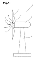
図1は、風エネルギから電気エネルギを発生させるための風力設備1の図式的な表示である。風力設備1は、ゴンドラ2を有しており、そのゴンドラがタワー3に回転可能に収容されている。ゴンドラ2内には、風力設備1のジェネレータのような、複数の電気機械的コンポーネントが配置されている。
FIG. 1 is a schematic representation of a
さらに、ロータ4が形成されており、そのロータはロータハブ5とそれに配置されたロータブレード6を有している。特に、ロータハブ5は軸受部材7によって回転運動可能にゴンドラ2に収容されている。
Further, a rotor 4 is formed, the rotor having a
軸受部材7がこの文書に記述される仕様に従って形成されていると、特に効果的である。その理由は、ゴンドラ2にロータハブ5を軸承するために軸受部材7が1つだけ使用される場合に、径方向力8も軸方向力9も、そして傾きモーメント10も1つの軸受部材7によって吸収されなければならないからである。軸方向力9は風の力によって生じる。径方向力8は、ロータ4の自重に相当し、かつロータ4の重心に作用する。ロータ4の重心は軸受部材7の外部に位置しているので、軸受部材7内に径方向力8によって傾きモーメント10がもたらされる。傾きモーメント10は、ロータブレード6の不均一な負荷によっても同様にもたらされることがある。
It is particularly effective if the bearing
軸受部材7を風力設備1内で使用する代わりに、このように形成された軸受部材7を、たとえばドレッジャのターンテーブルに使用すること、あるいは径方向力8及び/又は軸方向力8も、傾きモーメント10も軸受部材7に作用するところにおける、その他の適用も、考えられる。
Instead of using the bearing
本発明に係る軸受部材7は、たとえば0.5mと5mの間の直径を有することができる。もちろん軸受部材がそれより小さく、あるいは大きいことも、考えられる。
The bearing
図2には、軸受部材7の第1の実施例が、負荷を受けない状態において示されている。図3においては、図2に示す軸受部材7の第1の実施例が、傾きモーメントによって負荷を受けた状態において示されており、ここでも、先行する図2におけるのと同じ部分には同一の参照符号もしくは構成部分名称が使用される。不必要な繰り返しを避けるために、軸受部材7は図2と3を一緒に見たものに基づいて説明される。
FIG. 2 shows a first embodiment of the bearing
軸受部材7は、少なくとも1つの内側のリング部材11を有しており、それが内側12と外側13とを有している。さらに外側のリング部材14が設けられており、それが内側15と外側16とを有している。さらに内側のリング部材11と外側のリング部材14との間に滑り軸承部17が形成されており、その滑り軸承部が少なくとも2つの、互いに対して軸方向の間隔18で離隔した滑り軸受19を有している。2つの滑り軸受19は、それぞれ内側20と外側21とを有している。
The bearing
図2の表示においては、軸受部材7は負荷を受けない状態で示されている。負荷を受けない状態と定義されるのは、軸受部材7に力が作用せず、したがって重力も作用しない状態である。この状態は仮想であって、したがって軸受部材7の構成部分もしくは機能を説明するためだけに示されている。図2から明らかなように、軸受部材7が負荷を受けない状態において、内側のリング部材11と外側のリング部材14及び滑り軸受19は、共通の中央の長手軸線22に関して同心に配置されている。
In the display of FIG. 2, the bearing
図2〜6に示すような、軸受部材7の第1の実施例において、滑り軸受19は外側のリング部材14と結合されている。滑り軸受19の、外側のリング部材14と結合されている側は、この実施例においては滑り軸受の収容側23と称される。滑り軸受19の収容側23においては、滑り軸受19と外側のリング部材14との間に相対運動は行われない。滑り軸受部材19と外側のリング部材14とのこの種の結合は、たとえばオーストリア国特許第509625(B1)号明細書にすでに記述されているような措置によって達成することができる。
In the first embodiment of the bearing
さらに、滑り軸受19がたとえば接着結合によって外側のリング部材14内に収容されることも考えられる。更に、他の実施例においては、滑り軸受19がたとえば形状係合で外側のリング部材14内に収容されることも可能である。
Further, it is conceivable that the
滑り軸受19は、周面上に分配された複数のリング部材に分割することができる。さらに、滑り軸受19が唯一の一周するリングとして形成されることも、考えられる。この種の一周するリングは、たとえば外側のリング部材14内へ挿入することができ、摩擦結合によって外側のリング部材14に対して滑り軸受19が一緒に回転することは、阻止される。
The
滑り軸受19の収容側23に対向して、滑り面24が形成されており、その滑り面が内側のリング部材11の走行面25と協働する。第1の実施例において、内側のリング部材11の外側13が走行面25として形成されている。
A sliding
特に第1の実施例において、滑り軸受19が内側のリング部材11に対して回動し、滑り軸受19の滑り面24と内側のリング部材11の走行面25との間の滑り移動が可能になる。それによって軸受部材7の機能を実現することができる。軸受部材7の正確な機能又は正確な関係が図4〜6に詳細に示されており、又はこれらの表示は軸受部材7の第1の実施例を理解するための補足として用いられる。
In particular, in the first embodiment, the
図2に示すように、内側のリング部材11と滑り軸受19の間には、軸受のあそび26が形成されている。
As shown in FIG. 2, a bearing
ここで述べておくが、図2と3においても、図4〜6及び7〜9においても、軸受のあそび26は、はっきりさせるために過度に大きく示されている。特に図4〜6及び7〜9においては、機能及び技術的効果を見えるように示すことができるようにするために、滑り軸承の幾何学配置も著しく誇張して示されている。
As mentioned here, in FIGS. 2 and 3 as well as in FIGS. 4-6 and 7-9, the bearing
図2から明らかなように、2つの内側のリング11が形成されており、それらが互いに対して間隔27で配置されている。内側のリング部材11の外側13は、それぞれ円錐状に形成されており、かつ互いに向き合っている。2つの内側のリング部材11の互いに対する間隔27によって、軸受のあそび26を調節することができる。
As is clear from FIG. 2, two
走行面25は、中央の長手軸線22に関して回転対称に形成された面であり、その面は円錐台の特殊な形状を有することができる。図2に示すように、軸受部材7の横断面において、走行面25は直線を形成している。走行面25に接線28を引くと、この接線28は中央の長手軸線22に関して角度29で形成されている。
The traveling
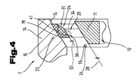
図2から、そして特に図4に示す拡大された表示から明らかなように、滑り軸受19はその滑り面24に第1の部分30と第2の部分31とを有している。
As is apparent from FIG. 2 and particularly from the enlarged display shown in FIG. 4, the
第1の部分30に引いた接線32は、中央の長手軸線22に対して角度33で配置されている。第2の部分31に引いた接線34は、中央の長手軸線22に対して角度35で配置されている。
The
特に、第2の部分32の角度35と第1の部分30の角度33は異なる大きさである。さらに、走行面25の角度29と第1の部分30の角度33は等しい大きさであって、したがって軸受部材7が負荷を受けない状態において、走行面25の接線28と第1の部分30の接線32は、互いに対して平行になる。したがって三次元の表示において見て、走行面25と第1の部分30は、等しい開口角度を有する円錐台の外表面を有している。
In particular, the
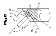
図5に示すように、軸受部材7が軸方向力9及び/又は径方向力8によって負荷を受けた場合に、滑り軸受19の滑り面24の第1の部分30と内側のリング部材11の走行面25とが第1の接触線36において添接する。したがって、滑り軸受19の滑り面24と内側のリング部材11の走行面25が第1の接触線36において互いに接触する。この理由は、径方向力8によって、もしくは軸方向力9によって2つの構成部分の互いに対する平行摺動がもたらされるからである。もちろん平行摺動は、百分の1から十分の1ミリメートルの領域内で移動し、かつ著しく誇張して示されている。
As shown in FIG. 5, when the bearing
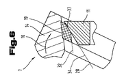
しかし、図3と6の表示に示すように軸受部材7内へ傾きモーメント10が導入された場合に、内側のリング部材11に対する外側のリング部材14の傾きがもたらされ、それによって滑り軸受19の滑り面24の第2の部分31が第2の接触線37において内側のリング部材11の走行面25に添接する。
However, when the
図3から明らかなように、2つの滑り軸受19は対角線状に対向して内側のリング部材11に載置される。このように傾いた場合に、特に回転点38に関して外側のリング部材14が内側のリング部材11に対して回動し、その回転点は中央の長手軸線22と長手中心軸線39の交点内に位置する。
As is clear from FIG. 3, the two
もちろん、外側のリング部材14が説明したように傾いた後に、走行面25の接線28と滑り軸受19の滑り面24の第2の部分31の接線34とが互いに等しく重なると、理想的である。それによって、軸受部材7が傾きモーメント10によって負荷を受けた場合でも、滑り面24と走行面25の間の線形状の接触がもたらされ、それによって面圧力とそれに伴って滑り面における摩耗を軽減することができる。
Of course, it is ideal that after the
傾いた後に第2の部分31の接線34と走行面25の接線28が等しく重なることは、滑り軸受19の構造において、図2に示す負荷を受けない状態において接線28が走行面25に接するものとされ、かつ回転点38に関して所定角度回動されるので、それが第2の部分31の接線34を形成し、かつ第1の部分30の接線32と滑り軸受19のほぼ中心で交差することによって、達成することができる。滑り軸受19の構造において接線28が走行面25に接して回動するこの角度の大きさが、次に最大の変位角度40°を定める。
The fact that the
第2の部分31の接線34と第1の部分30の接線32の間に開口角度41が形成され、その開口角度41は180°−(最大の変位角度40°)の角度に相当する。したがってそれなりに小さい軸受のあそび26が、百分の1ミリメートルから十分の1ミリメートルで移動する場合に、最大の変位角度40°も百分の1から十分の1度の領域内におちつく。
An
さらに、第1の部分30と第2の部分31の間に移行半径42を形成することができ、その移行半径は製造に基づくものである。好ましくは、移行半径42はできるだけ小さくされるので、第1の接触線36又は第2の接触線37はできる限り長くなり、したがって滑り軸受19の滑り面24と内側のリング部材11の走行面25の間に生じる面圧力はできるかぎり小さくなる。言い換えると、理想的な場合においては、第1の部分30と第2の部分31は、直接もしくは移行半径42なしで、互いに連続する。
Further, a transition radius 42 can be formed between the
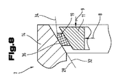
図7〜9には、第2の実施例において他の、そして場合によってはそれ自体自立した、軸受部材7の実施形態が示されており、ここでも先行する図2〜6におけるのと同じ部分には同一の参照符号又は構成部品名称が使用される。不必要な繰り返しを避けるために、先行する図2〜6における詳細な説明を参照する。
7-9 show another embodiment of the bearing
軸受部材7の第2の実施例においては、滑り軸受19は内側のリング部材11と結合することができ、滑り軸受19と外側のリング部材14との間で滑り移動が行われる。
In the second embodiment of the bearing
第2の実施例から明らかなように、滑り軸受19は内側のリング部材11と結合することができ、したがって滑り軸受19の収容側23はその内側20に形成することができる。それに従ってこの実施例においては、滑り軸受19の滑り面24はその外側21に形成されており、かつ、この実施例において走行面25として形成されている、外側のリング部材14の内側15と協働する。
As is apparent from the second embodiment, the
滑り軸受19の滑り面24の第1の部分30及び第2の部分31と、それと協働する外側のリング部材14の走行面25との間の関係は、図2から6においてすでに説明した第1の実施例と同様にふるまう。したがって簡単にするために、第2の実施例は別に詳細に説明せずに、当業者にとっては図2から6で説明した第1の実施例についての記述に基づいて、もしくは図7〜9に基づいて、機能は明らかである。
The relationship between the
図7〜9に示すように、内側に配置された滑り軸受19を有する軸受部材7のこの種の第2の実施例は、好ましくは、外側のリング部材14が固定位置に形成されており、かつ内側のリング部材11が滑り軸受部材19によって外側のリング部材14に対して回動可能である場合に、使用される。
As shown in FIGS. 7-9, in a second embodiment of this type of bearing
これらの実施例は、可能な実施変形例を示すものであって、ここで記録しておくが、本発明は具体的に示されたその実施変形例に限定されるものではなく、むしろ個々の実施変形例の互いに対する様々な組合せが可能であって、これらの変更可能性は具体的な発明による技術的に取り扱うための教示に基づいて、この技術分野で作業する当業者の裁量の範囲内にある。 These examples show possible embodiments and are recorded here, but the present invention is not limited to the specific embodiments thereof, but rather individual examples. Various combinations of embodiments are possible with respect to each other, and these modifiable possibilities are within the discretion of those skilled in the art working in the art, based on the teachings of the specific invention for technical handling. It is in.
保護領域は、請求項によって定められている。しかし明細書と図面は、請求項を解釈するために利用される。図示され、かつ説明された様々な実施例の個々の特徴又は特徴の組合せは、それ自体自立した進歩的解決を表すことができる。自立した進歩的解決の基礎となる課題は、明細書から読み取ることができる。 The protected area is defined by the claims. However, the specification and drawings are used to interpret the claims. The individual features or combinations of features of the various embodiments illustrated and described can represent themselves self-sustaining progressive solutions. The issues underlying self-sustaining progressive solutions can be read from the specification.
具体的な説明内の値領域についてのすべての記載は、その任意の部分領域とすべての部分領域を共に含むものであって、たとえば記載1から10は、下限の1と上限の10から始まるすべての部分領域、すなわち下限の1またはそれ以上で始まり、上限の10またはそれ以下で終了する、たとえば1から1.7、または3.2から8.1、あるいは5.5から10のすべての部分領域、を一緒に含んでいるものとする。
All descriptions of a value region in a specific description include both any subregion and all subregions, eg,
最後に形式的に指摘しておくが、構造を理解しやすくするために部材は部分的に縮尺通りではなく、かつ/又は拡大及び/又は縮小して示されている。 Finally, formally pointed out, the members are not partially scaled and / or enlarged and / or reduced to make the structure easier to understand.
1 風力設備
2 ゴンドラ
3 タワー
4 ロータ
5 ロータハブ
6 ロータブレード
7 軸受部材
8 径方向力
9 軸方向力
10 傾きモーメント
11 内側のリング部材
12 内側のリング部材の内側
13 内側のリング部材の外側
14 外側のリング部材
15 外側のリング部材の内側
16 外側のリング部材の外側
17 滑り軸承部
18 軸方向の間隔
19 滑り軸受
20 内側の滑り軸受
21 外側の滑り軸受
22 中央の長手軸線
23 収容側 滑り軸受
24 滑り面 滑り軸受
25 走行面
26 軸受のあそび
27 間隔 内側のリング部材
28 接線 走行面
29 角度 走行面
30 第1の部分
31 第2の部分
32 第1の部分の接線
33 第1の部分の角度
34 第2の部分の接線
35 第2の部分の角度
36 第1の接触線
37 第2の接触線
38 回転点
39 長手中心軸線
40 最大の変位角度
41 開口角度
42 移行半径
1 Wind equipment 2
Claims (9)
少なくとも1つの内側のリング部材(11)と少なくとも1つの外側のリング部材(14)を有し、それらが負荷を受けない状態において中央の長手軸線(22)に関して互いに同軸に配置され、前記内側のリング部材(11)と前記外側のリング部材(14)の間に滑り軸承部(17)が形成され、該滑り軸承部が少なくとも2つの、互いに対して軸方向の間隔(18)で配置された滑り軸受(19)によって形成され、該滑り軸受(19)が収容側(23)において前記内側のリング部材及び前記外側のリング部材(11、14)の1つと結合され、かつ収容側(23)と対向して滑り面(24)が形成され、該滑り面が対向する前記内側のリング部材及び前記外側のリング部材(11、14)の走行面(25)と協働する、軸受部材において、
前記滑り軸受(19)の新規状態において、該滑り軸受(19)の滑り面(24)が横断面で見て少なくとも1つの第1の部分(30)と第2の部分(31)とを有し、前記第1の部分(30)に添接する接線(32)が中央の長手軸線(22)に関して第1の角度(33)で配置され、前記第2の部分(31)に添接する接線(34)が中央の長手軸線(22)に関して第2の角度(35)で配置され、前記第1の角度(33)が前記第2の角度(35)と異なる大きさであり、
前記第1の部分(30)と前記第2の部分(31)とが、横断面で見て直線によって形成され、該直線が移行半径(42)によって互いに結合されている、ことを特徴とする軸受部材。 Radial force (8) and / or axial force (9) as well as for journalled a component for receiving the load by tilting moment (10), a bearing member (7),
It has at least one inner ring member (11) and at least one outer ring member (14) and is arranged coaxially with each other with respect to the central longitudinal axis (22) in a state where they are unloaded and said inner. A plain bearing (17) was formed between the ring member (11) and the outer ring member (14), and the plain bearings were arranged at least two at an axial distance (18) with respect to each other. Formed by a plain bearing (19), the plain bearing (19) is coupled to one of the inner ring member and the outer ring member (11, 14) on the accommodating side (23) and is coupled to the accommodating side (23). In the bearing member, a sliding surface (24) is formed so as to face the sliding surface, and the sliding surface cooperates with the traveling surface (25) of the inner ring member and the outer ring member (11, 14) facing the sliding surface.
In the new state of the plain bearing (19), the sliding surface (24) of the plain bearing (19) has at least one first portion (30) and a second portion (31) when viewed in cross section. The tangent line (32) attached to the first portion (30) is arranged at a first angle (33) with respect to the central longitudinal axis (22), and the tangent line attached to the second portion (31) ( 34) are arranged at a second angle (35) with respect to the central longitudinal axis (22), Ri said first angle (33) is sized der different from the second angle (35),
The first portion (30) and the second portion (31) are formed by a straight line when viewed in a cross section, and the straight line is connected to each other by a transition radius (42). Bearing member.
前記滑り軸受(19)が外側(21)に配置された前記滑り面(24)を有する場合に、前記第1の部分(30)に添接する接線(32)の、中央の長手軸線(22)に関する前記第1の角度(33)が、前記第2の部分(31)に添接する接線(34)の、中央の長手軸線(22)に関する前記第2の角度(35)よりも大きい、ことを特徴とする請求項1〜4の何れか一項に記載の軸受部材。 The central longitudinal axis (22) of the tangent (32) tangent to the first portion (30) when the plain bearing (19) has the sliding surface (24) disposed inside (20). The first angle (33) with respect to is smaller than the second angle (35) with respect to the central longitudinal axis (22) of the tangent (34) annexed to the second portion (31).
The central longitudinal axis (22) of the tangent (32) tangent to the first portion (30) when the plain bearing (19) has the sliding surface (24) disposed on the outside (21). That the first angle (33) with respect to is greater than the second angle (35) with respect to the central longitudinal axis (22) of the tangent (34) annexed to the second portion (31). The bearing member according to any one of claims 1 to 4, which is characterized.
前記軸受部材(7)が傾きモーメント(10)によって負荷を受けた場合に、前記内側のリング部材又は前記外側のリング部材(11、14)の前記走行面(25)が前記滑り軸受(19)の前記滑り面(24)の前記第2の部分(31)に、特に第2の接触線(37)に沿って添接し、前記内側のリング部材又は前記外側のリング部材(11、14)と前記滑り軸受(19)が中央の長手軸線(22)を中心に互いに対して相対回動可能である、ことを特徴とする請求項1〜5の何れか一項に記載の軸受部材。 When a load is applied to the bearing member (7) by the radial force (8) and / or the axial force (9), the traveling surface (11, 14) of the inner ring member or the outer ring member (11, 14). 25) is attached to the first portion (30) of the bearing member (7) of the slide bearing (19), particularly along the first contact line (36), and the inner ring member or the outer ring member. (11, 14) and the slide bearing (19) are rotatable relative to each other about the central longitudinal axis (22), and the bearing member (7) is loaded by the tilt moment (10). The running surface (25) of the inner ring member or the outer ring member (11, 14) receives the second portion (24) of the sliding surface (24) of the sliding bearing (19). 31), particularly along the second contact line (37), with the inner ring member or the outer ring member (11, 14) and the slide bearing (19) at the center of the longitudinal axis (22). The bearing member according to any one of claims 1 to 5, wherein the bearing members can rotate relative to each other with respect to each other.
前記軸受部材(7)が請求項1〜8の何れか一項に従って形成されている、ことを特徴とする風力設備。 In a wind turbine (1) having a rotor hub (5) and a gondola (2), the rotor hub (5) being pivotally supported by the gondola (2) by a bearing member (7).
A wind power facility, wherein the bearing member (7) is formed according to any one of claims 1 to 8.
Applications Claiming Priority (3)
| Application Number | Priority Date | Filing Date | Title |
|---|---|---|---|
| ATA50969/2016 | 2016-10-21 | ||
| ATA50969/2016A AT519288B1 (en) | 2016-10-21 | 2016-10-21 | bearing element |
| PCT/AT2017/060273 WO2018071941A1 (en) | 2016-10-21 | 2017-10-19 | Bearing element |
Publications (3)
| Publication Number | Publication Date |
|---|---|
| JP2019534428A JP2019534428A (en) | 2019-11-28 |
| JP2019534428A5 JP2019534428A5 (en) | 2020-10-08 |
| JP6970195B2 true JP6970195B2 (en) | 2021-11-24 |
Family
ID=60654568
Family Applications (1)
| Application Number | Title | Priority Date | Filing Date |
|---|---|---|---|
| JP2019521151A Active JP6970195B2 (en) | 2016-10-21 | 2017-10-19 | Bearing member |
Country Status (9)
| Country | Link |
|---|---|
| US (1) | US10598214B2 (en) |
| EP (1) | EP3529508B1 (en) |
| JP (1) | JP6970195B2 (en) |
| KR (1) | KR102416389B1 (en) |
| CN (1) | CN109790866B (en) |
| AT (1) | AT519288B1 (en) |
| DK (1) | DK3529508T3 (en) |
| ES (1) | ES2846974T3 (en) |
| WO (1) | WO2018071941A1 (en) |
Families Citing this family (15)
| Publication number | Priority date | Publication date | Assignee | Title |
|---|---|---|---|---|
| DE102018120810A1 (en) * | 2018-08-27 | 2020-02-27 | Renk Aktiengesellschaft | Bearing arrangement of a rotor of a wind turbine and wind turbine |
| DE102018120806A1 (en) * | 2018-08-27 | 2020-02-27 | Renk Aktiengesellschaft | Bearing arrangement of a rotor of a wind turbine |
| CN113508239B (en) * | 2018-12-03 | 2023-09-19 | Bmts科技有限及两合公司 | Exhaust gas turbocharger or hydrodynamic slide bearing with hydrodynamic slide bearing |
| AT521882B1 (en) | 2018-12-13 | 2021-05-15 | Miba Gleitlager Austria Gmbh | Plain bearings, in particular for a gearbox of a wind turbine |
| AT521775B1 (en) | 2018-12-13 | 2020-06-15 | Miba Gleitlager Austria Gmbh | Planetary gear for a wind turbine |
| AT521885B1 (en) | 2018-12-13 | 2020-09-15 | Miba Gleitlager Austria Gmbh | Gondola for a wind turbine |
| AT521884B1 (en) | 2018-12-13 | 2020-10-15 | Miba Gleitlager Austria Gmbh | Method for changing a slide bearing element of a rotor bearing of a wind turbine, as well as a nacelle for a wind turbine |
| AT522155B1 (en) | 2019-03-07 | 2020-09-15 | Miba Gleitlager Austria Gmbh | Plain bearing |
| AT522476B1 (en) * | 2019-05-21 | 2020-11-15 | Miba Gleitlager Austria Gmbh | Gondola for a wind turbine |
| DE102020112765A1 (en) | 2020-05-12 | 2021-11-18 | Miba Gleitlager Austria Gmbh | Main rotor bearing of a nacelle for a wind turbine |
| DE102020116588A1 (en) | 2020-06-24 | 2021-12-30 | Schaeffler Technologies AG & Co. KG | Angular contact sliding bearing |
| WO2022109635A1 (en) * | 2020-11-30 | 2022-06-02 | Miba Gleitlager Austria Gmbh | Method for assembling a rotor bearing of a wind turbine |
| EP4047228A1 (en) * | 2021-02-23 | 2022-08-24 | Flender GmbH | Bearing arrangement, generator transmission, wind turbine and computer program product |
| AT524591B1 (en) * | 2021-05-14 | 2022-07-15 | Miba Gleitlager Austria Gmbh | Gondola for a wind turbine |
| CN113339406B (en) * | 2021-05-26 | 2023-03-10 | 河南科技大学 | Bidirectional thrust conical sliding bearing |
Family Cites Families (34)
| Publication number | Priority date | Publication date | Assignee | Title |
|---|---|---|---|---|
| US3709573A (en) * | 1970-09-10 | 1973-01-09 | Kacarb Products Corp | Bearing construction |
| DE2235448C3 (en) | 1972-07-20 | 1975-06-26 | A. Friedr. Flender & Co, 4290 Bocholt | Planetary gear with load distribution of the tooth forces |
| FR2415747A1 (en) * | 1978-01-25 | 1979-08-24 | Greene Jerome | Hydrodynamic bearing with concave pressure pads - has evenly spaced cushions in two inclined rows to provide radial and thrust loading |
| US4243274A (en) * | 1978-08-28 | 1981-01-06 | Jerome Greene | Hydrodynamic bearing with radial, thrust and moment load capacity |
| US4245870A (en) * | 1979-04-06 | 1981-01-20 | Emerson Electric Co. | Electric motor bearing assembly |
| DE3816404A1 (en) * | 1988-05-13 | 1989-11-30 | Mtu Friedrichshafen Gmbh | THREE-MATERIAL SLIDING BEARING |
| US5732441A (en) * | 1994-04-06 | 1998-03-31 | Janian; Robert | Low friction wheel |
| DE29512636U1 (en) * | 1995-08-05 | 1995-10-05 | Intertractor Ag | Track roller track |
| US6296391B1 (en) * | 1997-06-09 | 2001-10-02 | Sankyo Seiki Mfg. Co., Ltd. | Hydrodynamic bearing apparatus |
| JP2002122134A (en) * | 2000-10-13 | 2002-04-26 | Nsk Ltd | Fluid bearing device |
| JP3955737B2 (en) * | 2001-03-07 | 2007-08-08 | 大同メタル工業株式会社 | Plain bearing |
| JP4096683B2 (en) * | 2002-10-07 | 2008-06-04 | 株式会社デンソー | Rotor support structure |
| DE10351524A1 (en) * | 2002-11-05 | 2004-08-12 | Roland Weitkamp | Rotor bearing arrangement for transferring rotor bending moments and torques for wind power plant has hub directly connected to inner ring of radial bearing or/and to bearing stiffening ring |
| JP2004308682A (en) * | 2003-04-02 | 2004-11-04 | Mitsubishi Materials Corp | Sintered oil retaining bearing |
| KR20050116395A (en) * | 2003-04-02 | 2005-12-12 | 미쓰비시 마테리알 가부시키가이샤 | Oil-impregnated sintered bearing and method of producing the same |
| KR20060059743A (en) * | 2004-11-29 | 2006-06-02 | 삼성전기주식회사 | A spindle motor having a hydrodynamic prerssure bearing |
| BE1017140A3 (en) * | 2006-05-15 | 2008-03-04 | Hansen Transmissions Int | PRESSER COMB FOR A GEAR GEAR TRANSMISSION. |
| EP2336583A4 (en) * | 2008-10-03 | 2013-08-07 | Taiho Kogyo Co Ltd | Sliding bearing and method of manufacturing same |
| JP5376448B2 (en) * | 2009-02-13 | 2013-12-25 | セイコーインスツル株式会社 | Bearing device and information recording / reproducing device |
| AT509625B1 (en) | 2010-04-14 | 2012-02-15 | Miba Gleitlager Gmbh | BEARING ELEMENT |
| JP5933552B2 (en) * | 2010-08-24 | 2016-06-15 | ボーグワーナー インコーポレーテッド | Exhaust turbocharger |
| DE102010053671A1 (en) * | 2010-12-07 | 2012-06-14 | Schaeffler Technologies Gmbh & Co. Kg | Multi-rowed rolling bearing for use in rotor bearing of wind-power plant, has outer ring comprising spherical outer surface, which cooperates with inner surface of housing, and bearing series formed by skew-angle roller bearing series |
| DE202012002913U1 (en) * | 2012-02-07 | 2012-04-19 | Imo Holding Gmbh | roller bearing assembly |
| PL2657519T3 (en) * | 2012-04-26 | 2015-11-30 | Siemens Ag | Wind turbine |
| JP2013245767A (en) * | 2012-05-25 | 2013-12-09 | Taiho Kogyo Co Ltd | Sliding bearing |
| EP2863076B1 (en) * | 2012-06-19 | 2021-02-24 | Fuji Electric Co., Ltd. | Composite sliding bearing and wind-powered electricity generation device using this bearing |
| DE102013221265A1 (en) * | 2013-10-21 | 2015-05-07 | Schaeffler Technologies Gmbh & Co. Kg | Planetary wheel bearing assembly |
| DE102014200725A1 (en) * | 2014-01-16 | 2015-07-30 | Schaeffler Technologies AG & Co. KG | Rotary connection with a self-locking bearing |
| EP2921728A1 (en) * | 2014-03-20 | 2015-09-23 | Areva Wind GmbH | Hybrid shaft bearing with a hydrodynamic bearing and a rolling bearing, wind generator comprising a hybrid shaft bearing, use of the hybrid shaft bearing and method of operating the hybrid shaft bearing |
| DE102014205637A1 (en) * | 2014-03-26 | 2015-10-01 | Aktiebolaget Skf | plain bearing system |
| ES2765403T3 (en) * | 2015-05-07 | 2020-06-09 | Flender Gmbh | Planetary transmission mechanism |
| EP3219984B1 (en) * | 2016-03-14 | 2019-01-02 | Siemens Aktiengesellschaft | Sliding bearing arrangement for a wind turbine |
| ES2814177T3 (en) * | 2016-09-02 | 2021-03-26 | Flender Gmbh | Planetary gear |
| EP3514397B1 (en) * | 2018-01-18 | 2020-08-19 | Siemens Gamesa Renewable Energy A/S | A bearing arrangement and a wind turbine |
-
2016
- 2016-10-21 AT ATA50969/2016A patent/AT519288B1/en active
-
2017
- 2017-10-19 JP JP2019521151A patent/JP6970195B2/en active Active
- 2017-10-19 KR KR1020197014327A patent/KR102416389B1/en active IP Right Grant
- 2017-10-19 WO PCT/AT2017/060273 patent/WO2018071941A1/en unknown
- 2017-10-19 ES ES17811827T patent/ES2846974T3/en active Active
- 2017-10-19 DK DK17811827.9T patent/DK3529508T3/en active
- 2017-10-19 US US16/334,390 patent/US10598214B2/en active Active
- 2017-10-19 CN CN201780059498.0A patent/CN109790866B/en active Active
- 2017-10-19 EP EP17811827.9A patent/EP3529508B1/en active Active
Also Published As
| Publication number | Publication date |
|---|---|
| KR102416389B1 (en) | 2022-07-04 |
| KR20190067883A (en) | 2019-06-17 |
| JP2019534428A (en) | 2019-11-28 |
| AT519288B1 (en) | 2018-07-15 |
| AT519288A1 (en) | 2018-05-15 |
| US20190234457A1 (en) | 2019-08-01 |
| ES2846974T3 (en) | 2021-07-30 |
| DK3529508T3 (en) | 2020-10-19 |
| CN109790866A (en) | 2019-05-21 |
| WO2018071941A1 (en) | 2018-04-26 |
| EP3529508A1 (en) | 2019-08-28 |
| US10598214B2 (en) | 2020-03-24 |
| EP3529508B1 (en) | 2020-08-12 |
| CN109790866B (en) | 2020-12-22 |
Similar Documents
| Publication | Publication Date | Title |
|---|---|---|
| JP6970195B2 (en) | Bearing member | |
| EP3219984B1 (en) | Sliding bearing arrangement for a wind turbine | |
| US7771127B2 (en) | Bearing assembly for supporting a transmission shaft in a housing | |
| EP3460238B1 (en) | Wind turbine | |
| EP2694810B1 (en) | Direct-drive wind turbine | |
| EP2568167A1 (en) | Direct-drive wind turbine | |
| JP2010508480A (en) | Bearing structure for rotatably supporting a planetary gear on a planetary carrier | |
| CN106460802A (en) | Roller-bearing arrangement and a wind turbine | |
| US9790920B2 (en) | Rotation driving mechanism for windmill | |
| JP2015514945A (en) | Bearing device | |
| US9726152B2 (en) | Rotation driving mechanism for windmill | |
| JP2022513175A (en) | Nacelle for wind turbines | |
| ES2902740T3 (en) | Large multi-row bearing | |
| JP6224278B1 (en) | Ball socket type tilting pad journal bearing | |
| US9358610B2 (en) | Device for supporting molten metal container | |
| JP2020525709A (en) | Rotational coupling mechanism for wind turbine generator and wind turbine generator equipped with rotational coupling mechanism for wind turbine generator | |
| CN105074204A (en) | A hub and bearing system and a turbine comprising the hub and bearing system | |
| EP2981713B1 (en) | A hub and bearing system and a turbine comprising the hub and bearing system | |
| JP2024517343A (en) | Nacelle for wind turbine | |
| JP2023551017A (en) | Plain bearing pads and plain bearings as well as wind turbine nacelles equipped with plain bearings | |
| JP5984978B2 (en) | Journal bearing device and rotating machine | |
| JP2006090345A (en) | Double row automatic aligning roller bearing and main shaft supporting structure of wind power generator | |
| KR20160007540A (en) | Improved pulley for high-efficiency winch |
Legal Events
| Date | Code | Title | Description |
|---|---|---|---|
| A521 | Request for written amendment filed |
Free format text: JAPANESE INTERMEDIATE CODE: A523 Effective date: 20200827 |
|
| A621 | Written request for application examination |
Free format text: JAPANESE INTERMEDIATE CODE: A621 Effective date: 20200827 |
|
| A977 | Report on retrieval |
Free format text: JAPANESE INTERMEDIATE CODE: A971007 Effective date: 20210528 |
|
| A131 | Notification of reasons for refusal |
Free format text: JAPANESE INTERMEDIATE CODE: A131 Effective date: 20210608 |
|
| A521 | Request for written amendment filed |
Free format text: JAPANESE INTERMEDIATE CODE: A523 Effective date: 20210908 |
|
| TRDD | Decision of grant or rejection written | ||
| A01 | Written decision to grant a patent or to grant a registration (utility model) |
Free format text: JAPANESE INTERMEDIATE CODE: A01 Effective date: 20210928 |
|
| A61 | First payment of annual fees (during grant procedure) |
Free format text: JAPANESE INTERMEDIATE CODE: A61 Effective date: 20211028 |
|
| R150 | Certificate of patent or registration of utility model |
Ref document number: 6970195 Country of ref document: JP Free format text: JAPANESE INTERMEDIATE CODE: R150 |