EP4047228A1 - Bearing arrangement, generator transmission, wind turbine and computer program product - Google Patents
Bearing arrangement, generator transmission, wind turbine and computer program product Download PDFInfo
- Publication number
- EP4047228A1 EP4047228A1 EP21158704.3A EP21158704A EP4047228A1 EP 4047228 A1 EP4047228 A1 EP 4047228A1 EP 21158704 A EP21158704 A EP 21158704A EP 4047228 A1 EP4047228 A1 EP 4047228A1
- Authority
- EP
- European Patent Office
- Prior art keywords
- bearing
- generator
- bearing arrangement
- designed
- rotor
- Prior art date
- Legal status (The legal status is an assumption and is not a legal conclusion. Google has not performed a legal analysis and makes no representation as to the accuracy of the status listed.)
- Withdrawn
Links
Images


Classifications
-
- F—MECHANICAL ENGINEERING; LIGHTING; HEATING; WEAPONS; BLASTING
- F16—ENGINEERING ELEMENTS AND UNITS; GENERAL MEASURES FOR PRODUCING AND MAINTAINING EFFECTIVE FUNCTIONING OF MACHINES OR INSTALLATIONS; THERMAL INSULATION IN GENERAL
- F16C—SHAFTS; FLEXIBLE SHAFTS; ELEMENTS OR CRANKSHAFT MECHANISMS; ROTARY BODIES OTHER THAN GEARING ELEMENTS; BEARINGS
- F16C17/00—Sliding-contact bearings for exclusively rotary movement
- F16C17/10—Sliding-contact bearings for exclusively rotary movement for both radial and axial load
-
- F—MECHANICAL ENGINEERING; LIGHTING; HEATING; WEAPONS; BLASTING
- F16—ENGINEERING ELEMENTS AND UNITS; GENERAL MEASURES FOR PRODUCING AND MAINTAINING EFFECTIVE FUNCTIONING OF MACHINES OR INSTALLATIONS; THERMAL INSULATION IN GENERAL
- F16C—SHAFTS; FLEXIBLE SHAFTS; ELEMENTS OR CRANKSHAFT MECHANISMS; ROTARY BODIES OTHER THAN GEARING ELEMENTS; BEARINGS
- F16C23/00—Bearings for exclusively rotary movement adjustable for aligning or positioning
- F16C23/02—Sliding-contact bearings
- F16C23/04—Sliding-contact bearings self-adjusting
-
- F—MECHANICAL ENGINEERING; LIGHTING; HEATING; WEAPONS; BLASTING
- F16—ENGINEERING ELEMENTS AND UNITS; GENERAL MEASURES FOR PRODUCING AND MAINTAINING EFFECTIVE FUNCTIONING OF MACHINES OR INSTALLATIONS; THERMAL INSULATION IN GENERAL
- F16C—SHAFTS; FLEXIBLE SHAFTS; ELEMENTS OR CRANKSHAFT MECHANISMS; ROTARY BODIES OTHER THAN GEARING ELEMENTS; BEARINGS
- F16C27/00—Elastic or yielding bearings or bearing supports, for exclusively rotary movement
- F16C27/02—Sliding-contact bearings
-
- F—MECHANICAL ENGINEERING; LIGHTING; HEATING; WEAPONS; BLASTING
- F16—ENGINEERING ELEMENTS AND UNITS; GENERAL MEASURES FOR PRODUCING AND MAINTAINING EFFECTIVE FUNCTIONING OF MACHINES OR INSTALLATIONS; THERMAL INSULATION IN GENERAL
- F16C—SHAFTS; FLEXIBLE SHAFTS; ELEMENTS OR CRANKSHAFT MECHANISMS; ROTARY BODIES OTHER THAN GEARING ELEMENTS; BEARINGS
- F16C27/00—Elastic or yielding bearings or bearing supports, for exclusively rotary movement
- F16C27/06—Elastic or yielding bearings or bearing supports, for exclusively rotary movement by means of parts of rubber or like materials
- F16C27/063—Sliding contact bearings
-
- F—MECHANICAL ENGINEERING; LIGHTING; HEATING; WEAPONS; BLASTING
- F16—ENGINEERING ELEMENTS AND UNITS; GENERAL MEASURES FOR PRODUCING AND MAINTAINING EFFECTIVE FUNCTIONING OF MACHINES OR INSTALLATIONS; THERMAL INSULATION IN GENERAL
- F16C—SHAFTS; FLEXIBLE SHAFTS; ELEMENTS OR CRANKSHAFT MECHANISMS; ROTARY BODIES OTHER THAN GEARING ELEMENTS; BEARINGS
- F16C2360/00—Engines or pumps
- F16C2360/31—Wind motors
-
- Y—GENERAL TAGGING OF NEW TECHNOLOGICAL DEVELOPMENTS; GENERAL TAGGING OF CROSS-SECTIONAL TECHNOLOGIES SPANNING OVER SEVERAL SECTIONS OF THE IPC; TECHNICAL SUBJECTS COVERED BY FORMER USPC CROSS-REFERENCE ART COLLECTIONS [XRACs] AND DIGESTS
- Y02—TECHNOLOGIES OR APPLICATIONS FOR MITIGATION OR ADAPTATION AGAINST CLIMATE CHANGE
- Y02E—REDUCTION OF GREENHOUSE GAS [GHG] EMISSIONS, RELATED TO ENERGY GENERATION, TRANSMISSION OR DISTRIBUTION
- Y02E10/00—Energy generation through renewable energy sources
- Y02E10/70—Wind energy
- Y02E10/72—Wind turbines with rotation axis in wind direction
Definitions
- the invention relates to a bearing arrangement for the rotatable mounting of a rotor shaft and a generator gearbox that has such a bearing arrangement.
- the invention also relates to a wind turbine equipped with such a generator gearbox.
- the invention relates to a computer program product which is designed to simulate an operating behavior of such a bearing arrangement.
- the European patent application EP 2 933 483 A1 discloses a drive system of a wind turbine that includes a multi-stage planetary gearbox connected to a generator.
- the generator has a rotor shaft which can be driven by a planetary stage and is rotatably held in bearings at both ends.
- the rotor shaft of the generator is held in plain bearings.
- a sliding bearing which is designed to support a rotor hub of a wind turbine which is subjected to changing wind loads during operation.
- the plain bearing is designed as a conical plain bearing which comprises cone elements pointing towards one another with their tips.
- Double-cone plain bearings are known, which serve to support a rotor shaft.
- the object of the invention is to provide a bearing arrangement which offers an improvement in at least one of the aspects described.
- a bearing arrangement which is designed to rotatably support a rotor shaft of a generator unit.
- a generator rotor of the generator unit can thus be driven via the rotor shaft.
- the bearing arrangement is designed to mount the rotor shaft so that it can rotate with respect to a housing wall that can belong to the generator unit.
- the bearing assembly includes at least one bearing capable of absorbing an overturning moment exerted on the rotor shaft. The tilting moment can be caused, among other things, by the weight of the generator rotor of the generator unit.
- the bearing is designed as at least one conical slide bearing.
- the conical slide bearing advantageously allows increased tilting moments to be absorbed and the rotor shaft to be mounted in a precisely aligned manner.
- rotor shafts of generators have higher speeds than, for example, multi-blade rotors of wind turbines.
- correspondingly increased tilting moments can be caused on the rotor shaft.
- the invention is based, among other things, on the surprising finding that conical slide bearings have sufficient load-bearing capacity, which also allow increased tilting moments caused by a generator rotor to be absorbed.
- the bearing arrangement according to the invention enables the use of generator rotors with an increased rated speed. This in turn makes it possible to use generator units with a reduced number of pole pairs, which allows weight to be saved.
- radial deflections of the generator rotor can be reduced during operation.
- the bearing arrangement according to the invention serves to increase a nominal speed of the generator rotor, save weight in the generator unit and/or reduce a generator air gap due to the bearing designed as a conical slide bearing.
- the bearing which is designed as a conical slide bearing, offers increased robustness when adjusting.
- the bearing is designed to support axial forces and/or radial forces that can act on the rotor shaft.
- an axial direction is understood to be essentially parallel to an axis of rotation of the rotor shaft, and a radial direction is to be understood as meaning any direction essentially perpendicular to the axial direction.
- the axial forces and/or radial forces can be generated by the generator rotor during operation.
- the radial forces include, among other things, the weight that is caused by the weight of the generator rotor itself. If the bearing arrangement is installed at an angle, the weight of the generator rotor itself can also cause an axial force on the rotor shaft.
- an axial force can also be caused by a force from a toothing, for example a helical toothing, which interacts with the rotor shaft.
- radial forces can also be caused by gyroscopic forces that arise during operation.
- Tapered plain bearings offer advantageous load-bearing capacity for axial and radial forces and thus allow the rotor shaft, and thus also the generator rotor, to be positioned exactly.
- the design of such a bearing arrangement is simplified, for example when it is intended to be used in a wind turbine.
- the design of separate radial bearings and axial bearings is unnecessary, which also results in a simplified supply of lubricant. This reduces the number of components in the claimed bearing arrangement.
- the conical sliding bearing can have a first and a second inner bearing sleeve.
- the conical sliding bearing can also have a first and second outer bearing sleeve.
- the inner and outer bearing sleeves each work together and in pairs already represent separate tapered plain bearings.
- a lubricant film can be formed between the inner and outer bearing sleeves by a corresponding supply of lubricant during operation, through which the principle of a plain bearing is realized.
- the first and second inner bearing sleeves can be arranged axially one behind the other, in particular directly adjacent to one another. Alternatively, the first and second bearing sleeves can also be designed in one piece and thus be different sections of a single component in the axial direction.
- first and second outer bearing sleeves can be arranged axially one behind the other, in particular directly adjacent to one another.
- the first and second outer bearing sleeves can be formed in one piece.
- the tapered plain bearing can be produced in a differential design, which offers a high degree of manufacturing precision. Increased manufacturing precision on the tapered plain bearing, in turn, ensures smoother running and reduced wear during operation, i.e. increased reliability.
- an axial adjustment for the rotor shaft is made possible in a simple manner.
- the first and second inner bearing sleeves can each be designed as cones or truncated cones pointing towards one another. This essentially results in an hourglass shape for the first and second inner bearing sleeve.
- the first and second outer bearing sleeves may have the complementary shape thereto. Due to their conical shape, there is a supporting effect on these in the axial direction, where an inner bearing sleeve is pressed against an outer bearing sleeve. Furthermore, when there is a tilting moment between the outer and inner bearing sleeves, there is an enlarged support surface. A so-called edge wear is thereby prevented, in particular in connection with a suitable profiling, so that the bearing arrangement claimed can also absorb increased tilting moments.
- the claimed bearing arrangement makes it possible to also store generator rotors with increased speeds, in which case correspondingly increased imbalances and gyroscopic forces can occur in any direction.
- the number of pole pairs can be reduced due to the increased tolerable nominal speeds of the generator rotor.
- sliding bearings in particular conical sliding bearings, offer a particularly advantageous damping behavior at increased speeds.
- the advantages of the claimed bearing arrangement outlined above are thus achieved to an increased extent.
- the inner bearing sleeve can integrally comprise the first and second inner bearing sleeve and can be designed as directly connected truncated cones pointing towards one another. The use of such a double truncated cone shape makes it possible to design the bearing arrangement claimed to be particularly compact in the axial direction.
- At least one of the inner or outer bearing sleeves can comprise a plurality of segments, each of which serves as a bearing segment.
- the plurality of segments is arranged circumferentially and thus functionally form the inner or outer bearing sleeve.
- the segments can be manufactured separately, further realizing the principle of the differential design.
- the production of the bearing arrangement can be designed in parallel without loss of precision, which allows for accelerated production.
- the design of the inner and outer bearing sleeve enables simplified and targeted repairs by replacing individual segments. It is also possible to set up a lubricating wedge over the entire respective tapered plain bearing.
- a gap between the segments can be used to collect and return lubricant that exits at the edges of the segments.
- the segments can essentially do this be trapezoidal, in particular in the form of curved trapezoidal surfaces.
- At least two adjacent segments can be designed to simultaneously provide lubricant films with different lubricant film thicknesses during operation.
- the segments can have different recesses, ie material recesses, essentially perpendicular to its surface wetted with lubricant, for example an inner surface or outer surface.
- the at least two segments arranged adjacent to one another can also be attached to one another with a radial offset in the conical sliding bearing.
- adjacent segments can be used to produce a profiling in the corresponding conical sliding bearing, which can be used to compensate for deformations and/or uneven load distributions.
- the at least two adjacent segments can be designed to form different lubricating wedges.
- the lubricating wedge is to be understood as meaning the shape of the lubricant film in the area of a plain bearing contact in a cross-sectional view.
- the segments can also be designed in some areas to form lubricant films with different lubricant film thicknesses and/or different lubricating wedges.
- edge wear can be avoided, for example.
- edge wear can be avoided, for example.
- the thickness of the lubricant film that occurs in each segment or in certain areas of a segment there is, for example, a different need for lubricant, a different development of heat and/or a different wear behavior.
- At least one of the circumferentially arranged segments can be designed as a spring element that is elastic perpendicular to the lubricant film formed there. Due to the conical shape of the conical plain bearing, the surface of the segment wetted with lubricant is suitable for springing in the axial and radial direction and for automatically adjusting its orientation relative to the axis of rotation of the rotor shaft by pressing on the complementary inner or outer bearing sleeve accordingly. Due to its elasticity, the tapered plain bearing is also suitable for absorbing abrupt deflections between the outer and inner bearing sleeve and avoiding a hard impact. Likewise, for example, when a tilting moment acts in the area of the corresponding segment, edge wear can be avoided. Consequently, the bearing arrangement claimed has a reliable and low-wear operating behavior even in operating situations that are associated with increased stresses.
- At least one of the segments can be designed as a double flexible segment which comprises at least two ring elements which are connected to one another in an edge area.
- the ring elements act as legs of a spring mechanism acting in the axial direction and radial direction.
- the ring elements together form a ring in the tapered plain bearing.
- Such double bending segments require a minimum of components and are therefore easy to produce.
- a ring element whose surface is wetted with lubricant during operation can thus be produced from a material which has advantageous sliding properties and/or exhibits increased dimensional accuracy after prolonged operation. For example, a geometry that is advantageous for plain bearing operation can be produced in the long term.
- a lubricating wedge ratio of 1:50 to 1:1000 can be guaranteed on the surface of the corresponding segment.
- a ring element whose surface is not wetted with lubricant during operation is made of a material with advantageous Spring properties can be produced.
- a functionally appropriate use of materials is possible, which offers an increased level of performance and also leads to increased cost efficiency.
- the inner bearing sleeves are ovalized on their outer surface.
- an outer bearing sleeve can also be ovalized on its inner surface.
- An ovalized shape is to be understood here as a deviation from the circular shape in cross section.
- a correspondingly ovalized shape can improve the sliding properties, for example an increase in the lubricant film in the conical plain bearing.
- the conical plain bearing can therefore be adapted for an operating state that is to be expected primarily, as a result of which the service life of the bearing arrangement is further increased.
- the bearing arrangement claimed is particularly suitable for wind turbines, for example offshore wind turbines.
- the bearing assembly claimed may include the rotor shaft itself.
- the rotor shaft can be cantilevered in the bearing arrangement claimed. Accordingly, a point of application for mechanical stresses acting on the rotor shaft, for example axial forces, radial forces and tilting moments, lies outside the bearing arrangement. As a result, a second bearing arrangement, which would have to be mounted axially on a side of the generator rotor facing away from the bearing arrangement claimed, is in particular unnecessary.
- the claimed bearing arrangement offers a resilient, reliable and long-lasting option for rotatably mounting a rotor shaft, so that when it is used, for example in a wind power plant, the assembly effort is reduced overall. Reducing the number of components also reduces the risk of a single component failing.
- first and second inner bearing sleeves can have different cone angles.
- the cone angle is to be understood here as the angle at the apex of the cone in a two-dimensional projection of the cone or of the truncated cone supplemented to form the cone. Due to the axially adjacent arrangement of the first and second inner bearing sleeves, the reaction behavior of the bearing arrangement can be adjusted depending on the direction, in particular against axial forces. As a result, the claimed bearing arrangement can be structurally adapted to a wide range of possible operating states in a simple manner. The range of uses of the claimed bearing arrangement is thus further increased.
- the rotor shaft of the claimed bearing arrangement can be designed to be driven directly via a planetary stage.
- the rotor shaft can interact with a sun wheel of the planetary stage at an end facing away from the generator rotor or can be designed in one piece with it.
- Direct driving is to be understood here as meaning that the rotor shaft follows a rotation of an output shaft of the gear stage, so there can be at most a minimal angular offset between them.
- the bearing arrangement claimed is particularly suitable as a bearing for a rotor shaft of a generator unit of a generator gearbox.
- the task is also solved by a generator transmission according to the invention.
- the generator transmission includes a transmission unit that includes at least one planetary stage.
- the transmission unit can be connected in a torque-transmitting manner to a main shaft, for example a main shaft of a wind turbine, in order to supply drive power.
- the generator unit is accommodated in the same housing as the transmission unit and is connected to the transmission unit on the output side in a torque-transmitting manner.
- the generator unit includes a generator rotor which is rotatably arranged in the generator unit.
- the generator rotor is attached to a rotor shaft in a rotationally fixed manner.
- the rotor shaft is accommodated in the housing of the generator gearbox.
- the rotor shaft is in accordance with the invention rotatably accommodated in a bearing arrangement which is designed according to one of the embodiments outlined above.
- Such generator transmissions which are also referred to as hybrid drives, are weight-saving, reliable and easy to assemble due to the bearing arrangement claimed.
- the claimed bearing arrangement can absorb, among other things, axial forces that are caused by the at least one planetary stage, which is connected to the rotor shaft in a torque-transmitting manner.
- this has a current carrying capacity that corresponds to at least 20 to 60 times, preferably 30 to 50 times, more preferably 37 to 43 times the current carrying capacity of a reference roller bearing.
- the reference roller bearing is a roller bearing, for example a tapered roller roller bearing, which from a mechanical point of view is suitable for replacing the bearing, ie is capable of being substituted.
- the reference roller bearing has the same inner and outer diameter and axial length.
- the reference roller bearing also has the same dynamic load capacity as the bearing and the same distances, which characterize the ability to absorb tilting moments.
- an increased sliding surface can be used, in particular due to the conical sliding bearing, which in turn achieves an increased current-carrying capacity.
- FIG 1 is shown schematically the structure of a first embodiment of the claimed bearing assembly 40 in a longitudinal section.
- the bearing arrangement 40 is arranged in a housing 31 of a transmission unit 30 which belongs to a generator transmission 50 .
- the bearing arrangement 40 comprises a rotor shaft 20 which can be rotated about a main axis of rotation 15 via which a drive power 25 can be transported.
- the rotor shaft 20 which is designed as a hollow shaft, is connected in a torque-proof manner to a sun wheel 24, which belongs to a planetary stage 33 of the transmission unit 30.
- a generator rotor 12 of a generator unit 10 is connected in a torque-proof manner to one end of the rotor shaft 20 on an output side 34 via a fastening means 22 .
- a functional dividing line between the generator unit 10 and the transmission unit 30 is shown in FIG 1 symbolized by the line with the reference number 11.
- the generator unit 10 and the transmission unit 30 together form a generator transmission 50 in which the generator unit 10 and the transmission unit 30 are accommodated in a housing 13 .
- the bearing assembly 40 also includes two bearings 41, which includes two tapered plain bearings 42.
- the tapered plain bearings 42 each include an outer bearing sleeve 44 and an inner bearing sleeve 46, between each of which a lubricant film 37 can be formed.
- a first and second inner bearing sleeve 46.1, 46.2 essentially have the shape of a truncated cone 48, with these pointing towards one another.
- the associated first and second bearing sleeves 44.1, 44.2 are of complementary design.
- the first and second inner bearing sleeves 46.1, 46.2 are spaced apart from one another by a spacer element 47 and are held axially on the rotor shaft 20 by securing means 43.
- the bearing arrangement 40 is suitable for absorbing a tilting moment 13 by means of the conical plain bearings 42 .
- the tilting moment 13 can be brought about by the weight of the generator rotor 12 , which is arranged to be rotatable about the main axis of rotation 15 .
- the tilting moment 13 can be caused, for example, by imbalances on the generator rotor 12, which in turn result in gyroscopic forces.
- the bearing arrangement 40 is also suitable, due to the conical plain bearings 42, for absorbing axial forces 18 and/or radial forces 19 which arise during operation of the generator rotor 12. Consequently, all typical stresses to be expected that occur during operation of the generator unit 10 can be accommodated with one type of bearing, ie the conical slide bearings 42 .
- the conical plain bearings 42 have an increased ability to absorb tilting moments 13 . Radial deflections 23 of the generator rotor 12 resulting from the tilting moments 13 are reduced by the bearing arrangement 40 . As a result, a reduced generator air gap 16 can be formed between the generator rotor 12 and a generator stator 14 .
- the generator air gap 16 has a reduced air gap height 17. As a result, electricity generation losses in the generator unit 10 are reduced.
- the generator rotor 12 is overhung on the rotor shaft 10 . Accordingly, axial forces 18, radial forces 19 and/or tilting moments 13 act via the fastening means 22, which is positioned outside of the bearing 41 in the axial direction 36.
- the bearing arrangement 40 is also suitable for absorbing axial forces 18 and/or radial forces 19, which are exerted on the rotor shaft 10 via the sun gear 24, and for introducing them into the housing 31 during normal operation. Due to the increased mechanical strength of the bearing arrangement 40, radial deflections 23 of the sun gear 24 are reduced. Excessive stresses on the planetary stage 33 can thus be avoided even at increased speeds of the generator rotor 12 .
- the bearing arrangement 40 can be used in a generator gearbox 50 which is suitable for use in a wind turbine 70 . Furthermore, the bearing arrangement 40 is depicted in a computer program product 80 which is designed to simulate the operating behavior of the bearing arrangement 40 .
- FIG 2 An outer bearing sleeve 44 for a tapered slide bearing 42 in a second embodiment of the bearing arrangement 40 claimed is in FIG 2 shown in a front view.
- the outer bearing sleeve 44 Arranged around the main axis of rotation 15 of the bearing arrangement 15 , the outer bearing sleeve 44 comprises a plurality of segments 58 .
- the segments 58 are essentially trapezoidal and are curved in a circumferential direction 51 .
- the surfaces of the segments 58 together form an inner surface 56 of the outer bearing sleeve 44, which is wetted with lubricant 35 during normal operation.
- the segments 44 are designed to support an inner bearing sleeve 46 in an axial direction 36 which is in FIG 2 extends into the drawing plane.
- the segments 58 thus form a truncated cone shape 48 with their inner surfaces 54.
- the segments 58 can be produced separately, so that assembly of the outer bearing sleeve 44 is simplified.
- the segments 58 each have a segment thickness 59 .
- a first segment 58.1 has a first segment thickness 59.1, which differs from a second segment thickness 59.2 of an adjacent second Segment 58.2 differs.
- a lubricant film thickness 45 can be formed on the first segment 58.1, which differs from a lubricant film thickness 45 on the second segment 58.2.
- the sliding behavior in a bearing arrangement 40 with a corresponding outer bearing sleeve 44 can consequently be adjusted overall by adjusting individual segments 58 .
- the bearing arrangement 40 can be used in a generator gearbox 50 which is suitable for use in a wind turbine 70 .
- the bearing arrangement 40 is depicted in a computer program product 80 which is designed to simulate the operating behavior of the bearing arrangement 40 .
- the inner bearing sleeves 46 ie the first and second inner bearing sleeves 46.1, 46.2, each comprise a plurality of segments 58 which are each designed as spring segments 21 which together form an outer surface 56 of the inner bearing sleeves 46.
- An intermediate space is formed by a sliding arm 27 of a spring segment 27 and an inner surface 54 of a corresponding outer bearing sleeve 44 , in which a lubricant film 37 is formed by lubricant 35 .
- the spring segment 21 is designed to exert a spring force essentially perpendicularly to the inner surface 54 of the outer bearing sleeve 44 and to correspondingly deform elastically.
- Spring segment 21 also includes a flexure arm 26 connected to inner bearing sleeve 46 at one end and to support arm 27 at an opposite end.
- the spring segment 21 is consequently designed as a so-called double bending segment 28 .
- the spring segment 21, ie the double bending segment 28 is designed as a ring element.
- the bending arm 26 can be produced from a material with advantageous elastic properties, for example spring steel.
- the support arm 27, however can be made from a material with advantageous sliding properties, for example a copper alloy.
- the spring segment 21 thus allows material to be used as required and thus offers low-wear and reliable operation.
- the bearing arrangement 40 can be used in a generator gearbox 50 which is suitable for use in a wind turbine 70 . Furthermore, the bearing arrangement 40 is depicted in a computer program product 80 which is designed to simulate the operating behavior of the bearing arrangement 40 .
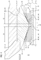
- a fourth embodiment of the claimed bearing arrangement 40 is in FIG 4 shown in a longitudinal section.
- the bearing 41 is designed as a conical slide bearing 42 with an outer bearing sleeve 44, which integrally includes the first and second outer bearing sleeve 44.1, 44.2.
- the first and second outer bearing sleeves 44.1, 44.2 form sections of the outer bearing sleeve 44 along the axial direction 36.
- the first outer bearing sleeve 44.1 has a greater axial length 53 than the second outer bearing sleeve 44.2.
- the first outer bearing sleeve 44.1 has a smaller cone angle 39 than the second bearing sleeve 44.2.
- the first and second bearing sleeves 44.1, 44.2 each essentially have a double truncated cone shape 48.
- the conical plain bearing 42 comprises a first and a second inner bearing sleeve 46.1, 46.2, which are designed as separate components.
- the first and second inner bearing sleeves 46.1, 46.2 are positioned in the axial direction 36 by a spacer element 47 which interacts with two securing means 43. Due to the different cone angles 39 and the different axial lengths 53 on the respective inner bearing sleeves 46, the supporting behavior of the conical plain bearing 42 can be adjusted depending on the direction, ie it can be configured asymmetrically.
- the bearing 41 that is to say the conical slide bearing 42, can be adjusted to the stress to be expected during operation.
- the bearing arrangement 40 can be used in a generator gearbox 50 which is suitable for use in a wind turbine 70 .
- the bearing arrangement 40 is depicted in a computer program product 80 which is designed to simulate the operating behavior of the bearing arrangement 40 .
- a fifth embodiment of the claimed bearing arrangement 40 is shown schematically in a detailed view in longitudinal section.
- the structure after 5 corresponded largely with the after FIG 1 .
- the one-piece outer bearing sleeve 44 has a cone angle 39 on its conical sections, ie on the first and second bearing sleeves 44.1, 44.2.
- the cone angle 39 on the first and second outer bearing sleeve 44.1, 44.2 are different.
- the correspondingly arranged first and second inner bearing sleeves 46.1, 46.2 also have different cone angles 39.
- the cone angle 39 of the first outer bearing sleeve 44.1 and the first inner bearing sleeve 46.1 arranged radially opposite are also different from one another.
- the cone angle 39 on the first inner bearing sleeve 46.1 and the first outer bearing sleeve 44.1 are designed in such a way that tilting as a result of the tilting moment 13 is made possible and edge wear is avoided. Such a tilting can be caused, for example, by a tilting moment 13 .
- a tilting moment 13 By selecting the corresponding cone angle 39 in the bearing arrangement 40, its support behavior when subjected to a tilting moment 13 can be adjusted as required.
- the bearing arrangement 40 can be used in a generator gearbox 50 which is suitable for use in a wind turbine 70 .
- the bearing arrangement 40 is depicted in a computer program product 80 which is designed to simulate the operating behavior of the bearing arrangement 40 .
- the wind turbine 70 includes a nacelle 71 in which a generator gear 50 is arranged, which is connected to a main shaft 73 in a torque-transmitting manner.
- the mainshaft 73 in turn is torque-transmittingly connected to a multi-blade rotor 72 on a drive side 32 rotatably attached to the nacelle 71 .
- the generator transmission 50 comprises a generator unit 10 on an output side 34 and a transmission unit 30 which are arranged in a common housing 31 .
- the transmission unit 30 includes at least one planetary stage 33, through which a speed on the main shaft 73 is converted to an increased speed of the generator unit 10.
- a bearing arrangement 40 for a rotor shaft 10 is accommodated in the generator transmission 50 and is designed according to one of the embodiments outlined above.
Abstract
Die Erfindung betrifft eine Lageranordnung (40) für eine Rotorwelle (20) einer Generatoreinheit (10), die ein kippmomentaufnehmendes Lager (41) mit einer inneren und einer äußeren Lagerhülse (44, 46) umfasst. Dieses ist zu einem Aufnehmen eines auf einen Generatorrotor (12) einwirkenden Kippdrehmoments (13) ausgebildet. Erfindungsgemäß ist das Lager (41) als Kegelgleitlager (42) ausgebildet. Die Erfindung betrifft auch ein Generatorgetriebe (50), das eine Getriebeeinheit (30) umfasst, die in einem Gehäuse (31) mit einer Generatoreinheit (10) mit einem Generatorrotor (12) angeordnet ist. Dabei ist der Generatorrotor (12) drehfest auf einer Rotorwelle (20) angebracht. Erfindungsgemäß ist die Rotorwelle (20) in einer korrespondierenden Lageranordnung (40) drehbar aufgenommen. Des Weiteren betrifft die Erfindung eine Windkraftanlage (70), die über ein solches Generatorgetriebe (50) verfügt. Ebenso betrifft die Erfindung ein Computerprogrammprodukt (80), das zu einem Simulieren eines Betriebsverhaltens einer entsprechenden Lageranordnung (40) ausgebildet ist.The invention relates to a bearing arrangement (40) for a rotor shaft (20) of a generator unit (10), which comprises a bearing (41) absorbing the tilting moment and having an inner and an outer bearing sleeve (44, 46). This is designed to absorb a tilting torque (13) acting on a generator rotor (12). According to the invention, the bearing (41) is designed as a conical plain bearing (42). The invention also relates to a generator gearbox (50) comprising a gearbox unit (30) which is arranged in a housing (31) with a generator unit (10) with a generator rotor (12). The generator rotor (12) is attached to a rotor shaft (20) in a rotationally fixed manner. According to the invention, the rotor shaft (20) is rotatably accommodated in a corresponding bearing arrangement (40). The invention also relates to a wind turbine (70) that has such a generator gear (50). The invention also relates to a computer program product (80) which is designed to simulate an operating behavior of a corresponding bearing arrangement (40).
Description
Die Erfindung betrifft eine Lageranordnung zur drehbaren Lagerung einer Rotorwelle und ein Generatorgetriebe, das über eine derartige Lageranordnung verfügt. Die Erfindung betrifft auch eine Windkraftanlage, die mit einem solchen Generatorgetriebe ausgestattet ist. Ferner betrifft die Erfindung ein Computerprogrammprodukt, das zu einem Simulieren eines Betriebsverhaltens einer solchen Lageranordnung ausgebildet ist.The invention relates to a bearing arrangement for the rotatable mounting of a rotor shaft and a generator gearbox that has such a bearing arrangement. The invention also relates to a wind turbine equipped with such a generator gearbox. Furthermore, the invention relates to a computer program product which is designed to simulate an operating behavior of such a bearing arrangement.
Die Europäische Patentanmeldung
Aus der Internationalen Anmeldung
Aus dem Konferenzbeitrag "
Im Bereich der Windkraftanlagentechnik besteht das Bestreben, Generatorgetriebe, also Getriebe mit integrierten Generatoren, mit steigenden Nennleistungen bereitzustellen, die gleichzeitig zuverlässig, gewichtssparend, kompakt und kosteneffizient sind. Lagerungen in solchen Anwendungen sind erhöhten mechanischen Beanspruchungen unterworfen. Der Erfindung liegt die Aufgabenstellung zugrunde, eine Lageranordnung bereitzustellen, die in zumindest einem der beschriebenen Aspekte eine Verbesserung bietet.In the field of wind turbine technology, there is a desire to use generator gears, i.e. gears with integrated generators, with increasing power ratings that are reliable, weight-saving, compact and cost-effective at the same time. Bearings in such applications are subject to increased mechanical stress. The object of the invention is to provide a bearing arrangement which offers an improvement in at least one of the aspects described.
Die Aufgabenstellung wird durch eine erfindungsgemäße Lageranordnung gelöst, die dazu ausgebildet ist, eine Rotorwelle einer Generatoreinheit drehbar zu lagern. Über die Rotorwelle ist somit ein Generatorrotor der Generatoreinheit antreibar. Die Lageranordnung ist dazu ausgebildet, die Rotorwelle gegenüber einer Gehäusewandung, die zur Generatoreinheit gehören kann, drehbar zu lagern. Die Lageranordnung umfasst zumindest ein Lager, das dazu geeignet ist, ein Kippmoment aufzunehmen, das auf die Rotorwelle ausgeübt wird. Das Kippmoment ist unter anderem durch das Eigengewicht des Generatorrotors der Generatoreinheit hervorrufbar. Erfindungsgemäß ist das Lager als zumindest ein Kegelgleitlager ausgebildet. Das Kegelgleitlager erlaubt es in vorteilhafter Weise, erhöhte Kippmomente aufzunehmen und dabei die Rotorwelle präzise ausgerichtet zu lagern. Rotorwellen von Generatoren weisen im Betrieb höhere Drehzahlen auf als beispielsweise Mehrblattrotoren von Windkraftanlagen. Im Zusammenwirken mit dem Eigengewicht des Generatorrotors und entsprechenden Drehzahlen können entsprechend erhöhte Kippmomente auf die Rotorwelle hervorgerufen werden. Der Erfindung liegt unter anderem die überraschende Erkenntnis zugrunde, dass Kegelgleitlager eine hinreichende Tragfähigkeit aufweisen, die auch das Aufnehmen von erhöhten Kippmomenten, die von einem Generatorrotor hervorgerufen werden, erlauben. Dementsprechend ermöglicht die erfindungsgemäße Lageranordnung die Verwendung von Generatorrotoren mit erhöhter Nenndrehzahl. Hierdurch wiederum sind Generatoreinheiten mit einer reduzierten Anzahl an Polpaaren einsetzbar, was eine Gewichtsersparnis erlaubt. Darüber hinaus sind Radialauslenkungen des Generatorrotors im Betrieb reduzierbar. Infolgedessen wird ein Berühren eines Generatorstators durch den Generatorrotor auch bei reduzierten Generatorluftspalten vermieden. Durch einen reduzierten, also in Radialrichtung verkleinerten, Generatorluftspalt ist die Effizienz der Generatoreinheit steigerbar. Insgesamt dient die erfindungsgemäße Lageranordnung durch das als Kegelgleitlager ausgebildete Lager zu einer Erhöhung einer Nenndrehzahl des Generatorrotor, einer Gewichtsersparnis in der Generatoreinheit und/oder einer Reduzierung eines Generatorluftspalts. Darüber hinaus bietet das als Kegelgleitlager ausgebildete Lager eine gesteigerte Robustheit beim Einstellen.The task is solved by a bearing arrangement according to the invention, which is designed to rotatably support a rotor shaft of a generator unit. A generator rotor of the generator unit can thus be driven via the rotor shaft. The bearing arrangement is designed to mount the rotor shaft so that it can rotate with respect to a housing wall that can belong to the generator unit. The bearing assembly includes at least one bearing capable of absorbing an overturning moment exerted on the rotor shaft. The tilting moment can be caused, among other things, by the weight of the generator rotor of the generator unit. According to the invention, the bearing is designed as at least one conical slide bearing. The conical slide bearing advantageously allows increased tilting moments to be absorbed and the rotor shaft to be mounted in a precisely aligned manner. During operation, rotor shafts of generators have higher speeds than, for example, multi-blade rotors of wind turbines. In conjunction with the generator rotor's own weight and corresponding speeds, correspondingly increased tilting moments can be caused on the rotor shaft. The invention is based, among other things, on the surprising finding that conical slide bearings have sufficient load-bearing capacity, which also allow increased tilting moments caused by a generator rotor to be absorbed. Accordingly, the bearing arrangement according to the invention enables the use of generator rotors with an increased rated speed. This in turn makes it possible to use generator units with a reduced number of pole pairs, which allows weight to be saved. In addition, radial deflections of the generator rotor can be reduced during operation. As a result, touching a generator stator avoided by the generator rotor even with reduced generator air gaps. The efficiency of the generator unit can be increased by a reduced generator air gap, ie one that is smaller in the radial direction. Overall, the bearing arrangement according to the invention serves to increase a nominal speed of the generator rotor, save weight in the generator unit and/or reduce a generator air gap due to the bearing designed as a conical slide bearing. In addition, the bearing, which is designed as a conical slide bearing, offers increased robustness when adjusting.
In einer Ausführungsform der beanspruchten Lageranordnung ist das Lager zu einem Abstützen von Axialkräften und /oder Radialkräften ausgebildet, die auf die Rotorwelle einwirken können. Unter einer Axialrichtung ist hierbei im Wesentlichen parallel zu einer Drehachse der Rotorwelle zu verstehen, unter einer Radialrichtung jegliche Richtung im Wesentlichen senkrecht zur Axialrichtung. Die Axialkräfte und/oder Radialkräfte sind im Betrieb durch den Generatorrotor hervorrufbar. Zu den Radialkräften gehört unter anderen die Gewichtskraft, die durch das Eigengewicht des Generatorrotors hervorgerufen wird. Bei einer geneigten Einbaulage der Lageranordnung kann durch das Eigengewicht des Generatorrotors auch eine Axialkraft auf die Rotorwelle hervorgerufen werden. Ferner kann eine Axialkraft auch durch eine Kraft aus einer Verzahnung, beispielsweise einer Schrägverzahnung, hervorgerufen werden, die mit der Rotorwelle zusammenwirkt. Des Weiteren können Radialkräfte auch durch Kreiselkräfte hervorgerufen werden, die sich im Betrieb einstellen. Kegelgleitlager bieten vorteilhafte Tragfähigkeit bei Axialkräften und Radialkräften und erlauben so eine exakte Positionierung der Rotorwelle, und damit auch des Generatorrotors. Darüber hinaus wird die Auslegung einer solchen Lageranordnung, beispielsweise bei einer vorgesehenen Verwendung in einer Windkraftanlage vereinfacht. Insbesondere ist die Auslegung separater Radiallager und Axiallager entbehrlich, wodurch sich ebenso eine vereinfachte Schmierstoffversorgung ergibt. Hierdurch wird die Bauteilanzahl in der beanspruchten Lageranordnung reduziert.In one embodiment of the claimed bearing arrangement, the bearing is designed to support axial forces and/or radial forces that can act on the rotor shaft. In this context, an axial direction is understood to be essentially parallel to an axis of rotation of the rotor shaft, and a radial direction is to be understood as meaning any direction essentially perpendicular to the axial direction. The axial forces and/or radial forces can be generated by the generator rotor during operation. The radial forces include, among other things, the weight that is caused by the weight of the generator rotor itself. If the bearing arrangement is installed at an angle, the weight of the generator rotor itself can also cause an axial force on the rotor shaft. Furthermore, an axial force can also be caused by a force from a toothing, for example a helical toothing, which interacts with the rotor shaft. Furthermore, radial forces can also be caused by gyroscopic forces that arise during operation. Tapered plain bearings offer advantageous load-bearing capacity for axial and radial forces and thus allow the rotor shaft, and thus also the generator rotor, to be positioned exactly. In addition, the design of such a bearing arrangement is simplified, for example when it is intended to be used in a wind turbine. In particular, the design of separate radial bearings and axial bearings is unnecessary, which also results in a simplified supply of lubricant. This reduces the number of components in the claimed bearing arrangement.
Ebenso kann in der beanspruchten Lageranordnung das Kegelgleitlager eine erste und eine zweite innere Lagerhülse aufweisen. Korrespondierend dazu kann das Kegelgleitlager auch eine erste und zweite äußere Lagerhülse aufweisen. Die inneren und äußeren Lagerhülsen wirken jeweils zusammen und stellen so paarweise bereits separate Kegelgleitlager dar. Zwischen den inneren und äußeren Lagerhülsen ist jeweils durch eine entsprechende Schmierstoffzufuhr im Betrieb ein Schmierstofffilm ausbildbar, durch den das Prinzip eines Gleitlagers verwirklicht wird. Die erste und zweite innere Lagerhülse können axial hintereinander angeordnet sein, insbesondere unmittelbar zueinander benachbart. Die erste und zweite Lagerhülse können alternativ auch einstückig ausgebildet sein und somit in Axialrichtung unterschiedliche Abschnitte einer einzigen Komponente sein. Korrespondierend dazu können die erste und zweite äußere Lagerhülse axial hintereinander, insbesondere unmittelbar zueinander benachbart, angeordnet sein. Gleichermaßen können die erste und zweite äußere Lagerhülse einstückig ausgebildet sein. Das Kegelgleitlager ist dadurch in Differentialbauweise herstellbar, was ein hohes Maß an Fertigungspräzision bietet. Eine gesteigerte Fertigungspräzision am Kegelgleitlager wiederum gewährleistet eine verbesserte Laufruhe und reduzierten Verschleiß im Betrieb, also erhöhte Zuverlässigkeit. Ebenso wird eine axiale Einstellung für die Rotorwelle in einfacher Weise ermöglicht.Likewise, in the bearing arrangement claimed, the conical sliding bearing can have a first and a second inner bearing sleeve. Correspondingly, the conical sliding bearing can also have a first and second outer bearing sleeve. The inner and outer bearing sleeves each work together and in pairs already represent separate tapered plain bearings. A lubricant film can be formed between the inner and outer bearing sleeves by a corresponding supply of lubricant during operation, through which the principle of a plain bearing is realized. The first and second inner bearing sleeves can be arranged axially one behind the other, in particular directly adjacent to one another. Alternatively, the first and second bearing sleeves can also be designed in one piece and thus be different sections of a single component in the axial direction. Correspondingly, the first and second outer bearing sleeves can be arranged axially one behind the other, in particular directly adjacent to one another. Equally, the first and second outer bearing sleeves can be formed in one piece. As a result, the tapered plain bearing can be produced in a differential design, which offers a high degree of manufacturing precision. Increased manufacturing precision on the tapered plain bearing, in turn, ensures smoother running and reduced wear during operation, i.e. increased reliability. Likewise, an axial adjustment for the rotor shaft is made possible in a simple manner.
In einer weiteren Ausführungsform der beanspruchten Lageranordnung können die erste und zweite innere Lagerhülse als jeweils aufeinander zuweisende Kegel oder Kegelstümpfe ausgebildet sein. Hieraus ergibt sich für die erste und zweite innere Lagerhülse im Wesentlichen eine Sanduhrform. Die erste und zweite äußere Lagerhülse können die dazu komplementäre Form aufweisen. Aufgrund deren konischer Form ergibt sich in Axialrichtung an diesen eine Stützwirkung, wo eine innere Lagerhülse gegen eine äußere Lagerhülse gedrückt wird. Des Weiteren ergeben sich bei einem einwirkenden Kippmoment zwischen den äußeren und inneren Lagerhülsen eine vergrößerte Stützfläche. Einem sogenannten Kantentragen wird dadurch, insbesondere in Verbindung mit einer geeigneten Profilierung, vorgebeugt, so dass die beanspruchte Lageranordnung auch erhöhte Kippmomente aufnehmen kann. Des Weiteren wird eine bidirektional wirkende Abstützung entlang der Axialrichtung und der Radialrichtung verwirklicht. Die beanspruchte Lageranordnung erlaubt es dadurch, auch Generatorrotoren mit erhöhten Drehzahlen zu lagern, bei denen entsprechend erhöhte Unwuchten und Kreiselkräfte in jegliche Richtung auftreten können. Durch die erhöhten erträglichen Nenndrehzahlen des Generatorrotors kann die Anzahl an Polpaaren reduziert werden. Ferner bieten Gleitlager, insbesondere Kegelgleitlager, bei erhöhten Drehzahlen ein besonders vorteilhaftes Dämpfungsverhalten. Die oben skizzierten Vorzüge der beanspruchten Lageranordnung werden somit in gesteigertem Ausmaß erzielt. Die innere Lagerhülse kann einstückig die erste und zweite innere Lagerhülse umfassen und als unmittelbar verbundene aufeinander weisende Kegelstümpfe ausgebildet sein. Die Verwendung einer derartigen doppelten Kegelstumpfform ermöglicht es, die beanspruchte Lageranordnung in Axialrichtung besonders kompakt auszubilden.In a further embodiment of the claimed bearing arrangement, the first and second inner bearing sleeves can each be designed as cones or truncated cones pointing towards one another. This essentially results in an hourglass shape for the first and second inner bearing sleeve. The first and second outer bearing sleeves may have the complementary shape thereto. Due to their conical shape, there is a supporting effect on these in the axial direction, where an inner bearing sleeve is pressed against an outer bearing sleeve. Furthermore, when there is a tilting moment between the outer and inner bearing sleeves, there is an enlarged support surface. A so-called edge wear is thereby prevented, in particular in connection with a suitable profiling, so that the bearing arrangement claimed can also absorb increased tilting moments. Furthermore, a bidirectionally acting support is realized along the axial direction and the radial direction. As a result, the claimed bearing arrangement makes it possible to also store generator rotors with increased speeds, in which case correspondingly increased imbalances and gyroscopic forces can occur in any direction. The number of pole pairs can be reduced due to the increased tolerable nominal speeds of the generator rotor. Furthermore, sliding bearings, in particular conical sliding bearings, offer a particularly advantageous damping behavior at increased speeds. The advantages of the claimed bearing arrangement outlined above are thus achieved to an increased extent. The inner bearing sleeve can integrally comprise the first and second inner bearing sleeve and can be designed as directly connected truncated cones pointing towards one another. The use of such a double truncated cone shape makes it possible to design the bearing arrangement claimed to be particularly compact in the axial direction.
Ferner kann zumindest eine der inneren oder äußeren Lagerhülsen eine Mehrzahl von Segmenten umfassen, die jeweils als Lagersegment dienen. Die Mehrzahl an Segmenten ist dabei umlaufend angeordnet und bilden so funktionell die innere bzw. äußere Lagerhülse. Die Segmente sind separat fertigbar, wodurch das Prinzip der Differentialbauweise weiter verwirklicht wird. Insbesondere ist die Fertigung der Lageranordnung so ohne Präzisionsverluste parallel gestaltbar, was eine beschleunigte Herstellung erlaubt. Der Aufbau der inneren bzw. äußeren Lagerhülse ermöglicht im Schadensfall eine vereinfachte und zielgerichtete Reparatur durch Austauschen einzelner Segmente. Ebenso wird der Aufbau eines Schmierkeils über das gesamte jeweilige Kegelgleitlager hinweg ermöglicht. Ferner ist ein Zwischenraum zwischen den Segmenten zu einem Sammeln und Rückführen von Schmierstoff nutzbar, der an den Rändern der Segmente austritt. Dazu können die Segmente im Wesentlichen trapezförmig ausgebildet sein, insbesondere in Form von gewölbten Trapezflächen.Furthermore, at least one of the inner or outer bearing sleeves can comprise a plurality of segments, each of which serves as a bearing segment. The plurality of segments is arranged circumferentially and thus functionally form the inner or outer bearing sleeve. The segments can be manufactured separately, further realizing the principle of the differential design. In particular, the production of the bearing arrangement can be designed in parallel without loss of precision, which allows for accelerated production. In the event of damage, the design of the inner and outer bearing sleeve enables simplified and targeted repairs by replacing individual segments. It is also possible to set up a lubricating wedge over the entire respective tapered plain bearing. Furthermore, a gap between the segments can be used to collect and return lubricant that exits at the edges of the segments. The segments can essentially do this be trapezoidal, in particular in the form of curved trapezoidal surfaces.
Darüber hinaus können zumindest zwei benachbarte Segmente, beispielsweise in Umfangsrichtung benachbart angeordnete Segmente, dazu ausgebildet sein, während des Betriebs gleichzeitig Schmierstofffilme mit unterschiedlichen Schmierstofffilmdicken bereitzustellen. Dazu können die Segmente im Wesentlichen senkrecht zu seiner mit Schmierstoff benetzten Oberfläche, beispielsweise einer Innenfläche oder Außenfläche, unterschiedliche Rücknahmen, also Materialrücknahmen, aufweisen. Alternativ oder ergänzend können die zumindest zwei benachbart angeordneten Segmente auch zueinander mit einem Radialversatz im Kegelgleitlager angebracht sein. Dadurch ist in einer Vielzahl an Belastungssituationen, also bei unterschiedlichen relativen Auslenkungen im Kegelgleitlager in Axialrichtung, Radialrichtung oder durch Verkippen durch ein Kippmoment, zumindest abschnittsweise ein Schmierstofffilm mit einer angestrebten Schmierstofffilmdicke herstellbar. Insbesondere ist über derartige benachbarte Segmente eine Profilierung im entsprechenden Kegelgleitlager herstellbar, durch die Deformationen und/oder ungleichmäßige Lastaufteilungen kompensierbar sind. Alternativ oder ergänzend können die zumindest zwei benachbarten Segmente dazu ausgebildet sein, unterschiedliche Schmierkeile auszubilden. Unter dem Schmierkeil ist die Form des Schmierstofffilms im Bereich eines Gleitlagerkontakts in einer Querschnittsansicht zu verstehen. Weiter alternativ oder ergänzend können die Segmente auch bereichsweise dazu ausgebildet sein, Schmierstofffilme von unterschiedlicher Schmierstofffilmdicke und/oder unterschiedliche Schmierkeile auszubilden. Dadurch ist beispielsweise ein sogenanntes Kantentragen vermeidbar. In Abhängigkeit von der sich je Segment oder bereichsweise an einem Segment einstellenden Schmierstofffilmdicke ergibt sich beispielsweise ein unterschiedlicher Schmierstoffbedarf, eine unterschiedliche Wärmeentwicklung und/oder ein unterschiedliches Verschleißverhalten. Diese Aspekte gehören zu einem Betriebsverhalten der Lageranordnung.In addition, at least two adjacent segments, for example segments arranged adjacent to one another in the circumferential direction, can be designed to simultaneously provide lubricant films with different lubricant film thicknesses during operation. For this purpose, the segments can have different recesses, ie material recesses, essentially perpendicular to its surface wetted with lubricant, for example an inner surface or outer surface. Alternatively or additionally, the at least two segments arranged adjacent to one another can also be attached to one another with a radial offset in the conical sliding bearing. As a result, a lubricant film with a desired lubricant film thickness can be produced at least in sections in a large number of load situations, i.e. with different relative deflections in the conical plain bearing in the axial direction, radial direction or due to tilting due to a tilting moment. In particular, such adjacent segments can be used to produce a profiling in the corresponding conical sliding bearing, which can be used to compensate for deformations and/or uneven load distributions. Alternatively or additionally, the at least two adjacent segments can be designed to form different lubricating wedges. The lubricating wedge is to be understood as meaning the shape of the lubricant film in the area of a plain bearing contact in a cross-sectional view. As a further alternative or in addition, the segments can also be designed in some areas to form lubricant films with different lubricant film thicknesses and/or different lubricating wedges. As a result, so-called edge wear can be avoided, for example. Depending on the thickness of the lubricant film that occurs in each segment or in certain areas of a segment, there is, for example, a different need for lubricant, a different development of heat and/or a different wear behavior. These aspects pertain to performance of the bearing assembly.
Des Weiteren kann zumindest eines der umlaufend angeordneten Segmente als Federelement ausgebildet sein, das senkrecht zum dort ausgebildeten Schmierstofffilm elastisch ist. Durch die Kegelform des Kegelgleitlagers ist die mit Schmierstoff benetzte Oberfläche des Segments dazu geeignet, in Axialrichtung und Radialrichtung zu federn und gegenüber der Drehachse der Rotorwelle seine Ausrichtung durch entsprechendes Andrücken der komplementären inneren bzw. äußeren Lagerhülse selbsttätig anzupassen. Durch die Elastizität ist das Kegelgleitlager dazu geeignet, auch abrupte Auslenkungen zwischen der äußeren und inneren Lagerhülse aufzunehmen und ein hartes Anschlagen zu vermeiden. Ebenso ist beispielsweise bei einem Einwirken eines Kippmoments im Bereich des entsprechenden Segments ein Kantentragen vermeidbar. Die beanspruchte Lageranordnung weist folglich auch in Betriebssituationen, die mit erhöhten Beanspruchungen einhergehen, ein zuverlässiges und verschleißarmes Betriebsverhalten auf.Furthermore, at least one of the circumferentially arranged segments can be designed as a spring element that is elastic perpendicular to the lubricant film formed there. Due to the conical shape of the conical plain bearing, the surface of the segment wetted with lubricant is suitable for springing in the axial and radial direction and for automatically adjusting its orientation relative to the axis of rotation of the rotor shaft by pressing on the complementary inner or outer bearing sleeve accordingly. Due to its elasticity, the tapered plain bearing is also suitable for absorbing abrupt deflections between the outer and inner bearing sleeve and avoiding a hard impact. Likewise, for example, when a tilting moment acts in the area of the corresponding segment, edge wear can be avoided. Consequently, the bearing arrangement claimed has a reliable and low-wear operating behavior even in operating situations that are associated with increased stresses.
Ferner kann zumindest eines der Segmente als Doppelbiegesegment ausgebildet sein, das zumindest zwei Ringelemente umfasst, die in einem Randbereich miteinander verbunden sind. Die Ringelemente wirken in einem Längsschnitt betrachtet als Schenkel eines in Axialrichtung und Radialrichtung wirkenden Federmechanismus. Die Ringelemente bilden in Umfangrichtung betrachtet zusammen einen Ring im Kegelgleitlager. Derartige Doppelbiegesegmente erfordern ein Minimum an Bauteilen und sind folglich in einfacher Weise herstellbar. Ein Ringelement, das im Betrieb an seiner Oberfläche mit Schmierstoff benetzt ist, ist dadurch aus einem Werkstoff herstellbar, der vorteilhafte Gleiteigenschaften aufweist und/oder nach längerem Betrieb eine erhöhte Maßhaltigkeit aufweist. Beispielsweise ist so dauerhaft eine für den Gleitlagerbetrieb vorteilhafte Geometrie herstellbar. Unter anderem kann an der Oberfläche des entsprechenden Segments ein Schmierkeilverhältnis von 1:50 bis 1:1000 gewährleistet werden. Ein Ringelement, das im Betrieb an seiner Oberfläche nicht mit Schmierstoff benetzt ist, ist aus einem Werkstoff mit vorteilhaften Federeigenschaften herstellbar. Dadurch ist ein funktionsgerechter Werkstoffeinsatz möglich, der ein gesteigertes Maß an Leistungsfähigkeit bietet und auch zu einer erhöhten Kosteneffizienz führt.Furthermore, at least one of the segments can be designed as a double flexible segment which comprises at least two ring elements which are connected to one another in an edge area. Viewed in a longitudinal section, the ring elements act as legs of a spring mechanism acting in the axial direction and radial direction. Viewed in the circumferential direction, the ring elements together form a ring in the tapered plain bearing. Such double bending segments require a minimum of components and are therefore easy to produce. A ring element whose surface is wetted with lubricant during operation can thus be produced from a material which has advantageous sliding properties and/or exhibits increased dimensional accuracy after prolonged operation. For example, a geometry that is advantageous for plain bearing operation can be produced in the long term. Among other things, a lubricating wedge ratio of 1:50 to 1:1000 can be guaranteed on the surface of the corresponding segment. A ring element whose surface is not wetted with lubricant during operation is made of a material with advantageous Spring properties can be produced. As a result, a functionally appropriate use of materials is possible, which offers an increased level of performance and also leads to increased cost efficiency.
In einer weiteren Ausführungsform der beanspruchten Lageranordnung sind die innere Lagerhülse and ihrer Außenfläche ovalisiert ausgebildet. Alternativ oder ergänzend kann auch eine äußere Lagerhülse an ihrer Innenfläche ovalisiert ausgebildet sein. Unter einer ovalisierten Form ist hierbei im Querschnitt eine Abweichung von der Kreisform zu verstehen. Durch eine entsprechend ovalisierte Form ist eine Verbesserung der Gleiteigenschaften, beispielsweise eine Vergrößerung des Schmierstofffilms im Kegelgleitlager, erreichbar. Das Kegelgleitlager ist daher für einen vorrangig zu erwartenden Betriebszustand anpassbar, wodurch die Lebensdauer der beanspruchten Lageranordnung weiter gesteigert wird. Die beanspruchte Lageranordnung ist infolgedessen besonders für Windkraftanlagen, beispielsweise Offshore-Windkraftanlagen, geeignet.In a further embodiment of the claimed bearing arrangement, the inner bearing sleeves are ovalized on their outer surface. Alternatively or additionally, an outer bearing sleeve can also be ovalized on its inner surface. An ovalized shape is to be understood here as a deviation from the circular shape in cross section. A correspondingly ovalized shape can improve the sliding properties, for example an increase in the lubricant film in the conical plain bearing. The conical plain bearing can therefore be adapted for an operating state that is to be expected primarily, as a result of which the service life of the bearing arrangement is further increased. As a result, the bearing arrangement claimed is particularly suitable for wind turbines, for example offshore wind turbines.
Darüber hinaus kann die beanspruchte Lageranordnung die Rotorwelle selbst umfassen. Die Rotorwelle kann dabei fliegend in der beanspruchten Lageranordnung gelagert sein. Dementsprechend liegt ein Angriffspunkt für mechanische Beanspruchungen, die auf die Rotorwelle einwirken, beispielsweise Axialkräfte, Radialkräfte und Kippmomente, außerhalb der Lageranordnung. Dadurch ist insbesondere eine zweite Lageranordnung, die axial auf einer der beanspruchten Lageranordnung abgewandten Seite des Generatorrotors anzubringen wäre, entbehrlich. Die beanspruchte Lageranordnung bietet eine belastbare, zuverlässige und langlebige Möglichkeit, eine Rotorwelle drehbar zu lagern, so dass bei einer Verwendung, beispielsweise in einer Windkraftanlage, insgesamt der Montageaufwand reduziert ist. Durch die Reduzierung der Bauteile wird auch das Risiko eines Ausfalls einer einzelnen Komponente reduziert.In addition, the bearing assembly claimed may include the rotor shaft itself. The rotor shaft can be cantilevered in the bearing arrangement claimed. Accordingly, a point of application for mechanical stresses acting on the rotor shaft, for example axial forces, radial forces and tilting moments, lies outside the bearing arrangement. As a result, a second bearing arrangement, which would have to be mounted axially on a side of the generator rotor facing away from the bearing arrangement claimed, is in particular unnecessary. The claimed bearing arrangement offers a resilient, reliable and long-lasting option for rotatably mounting a rotor shaft, so that when it is used, for example in a wind power plant, the assembly effort is reduced overall. Reducing the number of components also reduces the risk of a single component failing.
Des Weiteren können die erste und zweite innere Lagerhülse unterschiedliche Kegelwinkel aufweisen. Unter dem Kegelwinkel ist hierbei der Winkel an der Kegelspitze in einer zweidimensionalen Projektion des Kegels bzw. des zum Kegel ergänzten Kegelstumpfs zu verstehen. Durch die axial benachbarte Anordnung der ersten und zweiten inneren Lagerhülse ist dadurch das Reaktionsverhalten der Lageranordnung richtungsabhängig einstellbar, insbesondere gegen Axialkräfte. Die beanspruchte Lageranordnung ist dadurch konstruktiv in einfacher Weise an eine breite Spanne von möglichen Betriebszuständen anpassbar. Das Einsatzspektrum der beanspruchten Lageranordnung wird so weiter vergrößert.Furthermore, the first and second inner bearing sleeves can have different cone angles. The cone angle is to be understood here as the angle at the apex of the cone in a two-dimensional projection of the cone or of the truncated cone supplemented to form the cone. Due to the axially adjacent arrangement of the first and second inner bearing sleeves, the reaction behavior of the bearing arrangement can be adjusted depending on the direction, in particular against axial forces. As a result, the claimed bearing arrangement can be structurally adapted to a wide range of possible operating states in a simple manner. The range of uses of the claimed bearing arrangement is thus further increased.
Ferner kann die Rotorwelle der beanspruchten Lageranordnung unmittelbar über eine Planetenstufe antreibbar ausgebildet sein. Die Rotorwelle kann dazu an einem dem Generatorrotor abgewandten Ende mit einem Sonnenrad der Planetenstufe zusammenwirken oder einstückig mit diesem ausgebildet sein. Unter einem unmittelbaren Antreiben ist hierbei zu verstehen, dass die Rotorwelle einer Drehung einer Ausgangswelle der Getriebestufe folgt, zwischen diesen also höchstens ein minimaler Winkelversatz vorliegen kann. Die beanspruchte Lageranordnung ist in besonderer Weise als Lager für eine Rotorwelle einer Generatoreinheit eines Generatorgetriebes geeignet.Furthermore, the rotor shaft of the claimed bearing arrangement can be designed to be driven directly via a planetary stage. For this purpose, the rotor shaft can interact with a sun wheel of the planetary stage at an end facing away from the generator rotor or can be designed in one piece with it. Direct driving is to be understood here as meaning that the rotor shaft follows a rotation of an output shaft of the gear stage, so there can be at most a minimal angular offset between them. The bearing arrangement claimed is particularly suitable as a bearing for a rotor shaft of a generator unit of a generator gearbox.
Die Aufgabenstellung wird ebenso durch ein erfindungsgemäßes Generatorgetriebe gelöst. Das Generatorgetriebe umfasst eine Getriebeeinheit, die zumindest eine Planetenstufe umfasst. Die Getriebeeinheit ist mit einer Hauptwelle, beispielsweise einer Hauptwelle einer Windkraftanlage, drehmomentübertragend verbindbar um eine Antriebsleistung zuzuführen. Die Generatoreinheit ist im gleichen Gehäuse wie die Getriebeeinheit aufgenommen und ist mit der Getriebeeinheit abtriebsseitig drehmomentübertragend verbunden. Die Generatoreinheit umfasst einen Generatorrotor, der drehbar in der Generatoreinheit angeordnet ist. Dabei ist der Generatorrotor drehfest auf einer Rotorwelle angebracht. Die Rotorwelle ist im Gehäuse des Generatorgetriebes aufgenommen. Die Rotorwelle ist dabei erfindungsgemäß in einer Lageranordnung drehbar aufgenommen, die nach einer der oben skizzierten Ausführungsformen ausgebildet ist. Derartige Generatorgetriebe, die auch als Hybrid Drives bezeichnet werden, sind durch die beanspruchte Lageranordnung gewichtssparend, zuverlässig und -einfach zu montieren. Ferner sind durch die beanspruchte Lageranordnung unter anderem Axialkräfte aufnehmbar, die durch die zumindest eine Planetenstufe hervorgerufen werden, die mit der Rotorwelle drehmomentübertragend verbunden ist.The task is also solved by a generator transmission according to the invention. The generator transmission includes a transmission unit that includes at least one planetary stage. The transmission unit can be connected in a torque-transmitting manner to a main shaft, for example a main shaft of a wind turbine, in order to supply drive power. The generator unit is accommodated in the same housing as the transmission unit and is connected to the transmission unit on the output side in a torque-transmitting manner. The generator unit includes a generator rotor which is rotatably arranged in the generator unit. The generator rotor is attached to a rotor shaft in a rotationally fixed manner. The rotor shaft is accommodated in the housing of the generator gearbox. The rotor shaft is in accordance with the invention rotatably accommodated in a bearing arrangement which is designed according to one of the embodiments outlined above. Such generator transmissions, which are also referred to as hybrid drives, are weight-saving, reliable and easy to assemble due to the bearing arrangement claimed. Furthermore, the claimed bearing arrangement can absorb, among other things, axial forces that are caused by the at least one planetary stage, which is connected to the rotor shaft in a torque-transmitting manner.
In einer Ausführungsform des beanspruchten Generatorgetriebes weist dieses eine Strombelastbarkeit auf, die zumindest dem 20-fachen bis 60-fachen, bevorzugt dem 30-fachen bis 50-fachen, weiter bevorzugt dem 37-fachen bis 43-fachen, einer Strombelastbarkeit eines Referenzwälzlagers entspricht. Unter dem Referenzwälzlager ist ein Wälzlager, beispielsweis ein Kegelrollenwälzlager zu verstehen, das unter mechanischen Gesichtspunkten dazu geeignet ist, das Lager zu ersetzen, also substitutionsfähig ist. Das weist das Referenzwälzlager gleiche Innen- und Außendurchmesser und axiale Länge auf. Ebenso weist das Referenzwälzlager eine gleiche dynamische Tragfähigkeit auf wie das Lager und gleiche Abstände, die die Aufnahmefähigkeit für Kippmoment charakterisiert. Im beanspruchten Generatorgetriebe ist insbesondere durch das Kegelgleitlager eine erhöhte Gleitfläche nutzbar, durch die wiederum eine gesteigerte Strombelastbarkeit erzielt wird.In one embodiment of the claimed generator transmission, this has a current carrying capacity that corresponds to at least 20 to 60 times, preferably 30 to 50 times, more preferably 37 to 43 times the current carrying capacity of a reference roller bearing. The reference roller bearing is a roller bearing, for example a tapered roller roller bearing, which from a mechanical point of view is suitable for replacing the bearing, ie is capable of being substituted. The reference roller bearing has the same inner and outer diameter and axial length. The reference roller bearing also has the same dynamic load capacity as the bearing and the same distances, which characterize the ability to absorb tilting moments. In the claimed generator transmission, an increased sliding surface can be used, in particular due to the conical sliding bearing, which in turn achieves an increased current-carrying capacity.
Die Erfindung wird im Folgenden anhand einzelner Ausführungsformen in Figuren näher erläutert. Die Figuren sind insoweit in gegenseitiger Ergänzung zu lesen, dass gleiche Bezugszeichen in unterschiedlichen Figuren die gleiche technische Bedeutung haben. Die Merkmale der einzelnen Ausführungsformen sind untereinander auch kombinierbar. Ferner sind die in den Figuren gezeigten Ausführungsformen mit den oben skizzierten Merkmalen kombinierbar. Es zeigen im Einzelnen:
- FIG 1
- schematisch eine erste Ausführungsform der beanspruchten Lageranordnung im Längsschnitt;
- FIG 2
- eine äußere Lagerhülse für eine zweite Ausführungsform der beanspruchten Lageranordnung in einer Stirnansicht;
- FIG 3
- schematisch eine dritte Ausführungsform der beanspruchten Lageranordnung in einer Detailansicht im Längsschnitt;
- FIG 4
- schematisch eine vierte Ausführungsform der beanspruchten Lageranordnung in einer Detailansicht im Längsschnitt;
- FIG 5
- schematisch eine fünfte Ausführungsform der beanspruchten Lageranordnung in einer Detailansicht im Längsschnitt;
- FIG 6
- schematisch eine Ausführungsform einer beanspruchten Windkraftanlage in einer geschnittenen Schrägansicht.
- FIG 1
- schematically a first embodiment of the claimed bearing assembly in longitudinal section;
- FIG 2
- an outer bearing sleeve for a second embodiment of the claimed bearing arrangement in a front view;
- 3
- schematically a third embodiment of the claimed bearing assembly in a detailed view in longitudinal section;
- FIG 4
- schematically a fourth embodiment of the claimed bearing assembly in a detailed view in longitudinal section;
- 5
- schematically a fifth embodiment of the claimed bearing assembly in a detailed view in longitudinal section;
- 6
- schematically an embodiment of a claimed wind turbine in a sectional oblique view.
In
Der Generatorrotor 12 ist auf der Rotorwelle 10 fliegend gelagert. Dementsprechend erfolgt ein Einwirken von Axialkräften 18, Radialkräften 19 und/oder Kippmomenten 13 über das Befestigungsmittel 22, das in Axialrichtung 36 außerhalb des Lagers 41 positioniert ist. Die Lageranordnung 40 ist auch dazu geeignet, im bestimmungemäßen Betrieb Axialkräfte 18 und/oder Radialkräfte 19, die über das Sonnenrad 24 auf die Rotorwelle 10 ausgeübt werden, aufzunehmen und in das Gehäuse 31 einzuleiten. Durch die erhöhte mechanische Beanspruchbarkeit der Lageranordnung 40 sind Radialauslenkungen 23 des Sonnenrads 24 reduziert. Auch bei erhöhten Drehzahlen des Generatorrotors 12 sind so übermäßige Beanspruchungen der Planetenstufe 33 vermeidbar. Die Lageranordnung 40 ist in einem Generatorgetriebe 50 einsetzbar, das zur Verwendung in einer Windkraftanlage 70 geeignet ist. Ferner ist die Lageranordnung 40 in einem Computerprogrammprodukt 80 abgebildet, das zu einem Simulieren des Betriebsverhaltens der Lageranordnung 40 ausgebildet ist.The
Eine äußere Lagerhülse 44 für ein Kegelgleitlager 42 in einer zweiten Ausführungsform der beanspruchten Lageranordnung 40 ist in
Eine vierte Ausführungsform der beanspruchten Lageranordnung 40 ist in
In
Eine Ausführungsform einer beanspruchten Windkraftanlage 70 ist schematisch in
Claims (16)
Priority Applications (1)
| Application Number | Priority Date | Filing Date | Title |
|---|---|---|---|
| EP21158704.3A EP4047228A1 (en) | 2021-02-23 | 2021-02-23 | Bearing arrangement, generator transmission, wind turbine and computer program product |
Applications Claiming Priority (1)
| Application Number | Priority Date | Filing Date | Title |
|---|---|---|---|
| EP21158704.3A EP4047228A1 (en) | 2021-02-23 | 2021-02-23 | Bearing arrangement, generator transmission, wind turbine and computer program product |
Publications (1)
| Publication Number | Publication Date |
|---|---|
| EP4047228A1 true EP4047228A1 (en) | 2022-08-24 |
Family
ID=74732607
Family Applications (1)
| Application Number | Title | Priority Date | Filing Date |
|---|---|---|---|
| EP21158704.3A Withdrawn EP4047228A1 (en) | 2021-02-23 | 2021-02-23 | Bearing arrangement, generator transmission, wind turbine and computer program product |
Country Status (1)
| Country | Link |
|---|---|
| EP (1) | EP4047228A1 (en) |
Citations (7)
| Publication number | Priority date | Publication date | Assignee | Title |
|---|---|---|---|---|
| US20150017000A1 (en) * | 2012-06-19 | 2015-01-15 | Fuji Electric Co., Ltd. | Composite sliding bearing and wind power generating device using the same bearing |
| EP2933483A1 (en) | 2014-04-15 | 2015-10-21 | Siemens Aktiengesellschaft | Drive system for a wind turbine |
| EP3290751A1 (en) * | 2016-09-02 | 2018-03-07 | Flender GmbH | Planetary gear unit |
| WO2018071941A1 (en) * | 2016-10-21 | 2018-04-26 | Miba Gleitlager Austria Gmbh | Bearing element |
| WO2019020213A1 (en) | 2017-07-25 | 2019-01-31 | Rheinisch-Westfälische Technische Hochschule Aachen | Plain bearing device |
| WO2020118334A1 (en) * | 2018-12-13 | 2020-06-18 | Miba Gleitlager Austria Gmbh | Nacelle for a wind turbine |
| WO2020176918A1 (en) * | 2019-03-07 | 2020-09-10 | Miba Gleitlager Austria Gmbh | Plain bearing arrangement |
-
2021
- 2021-02-23 EP EP21158704.3A patent/EP4047228A1/en not_active Withdrawn
Patent Citations (7)
| Publication number | Priority date | Publication date | Assignee | Title |
|---|---|---|---|---|
| US20150017000A1 (en) * | 2012-06-19 | 2015-01-15 | Fuji Electric Co., Ltd. | Composite sliding bearing and wind power generating device using the same bearing |
| EP2933483A1 (en) | 2014-04-15 | 2015-10-21 | Siemens Aktiengesellschaft | Drive system for a wind turbine |
| EP3290751A1 (en) * | 2016-09-02 | 2018-03-07 | Flender GmbH | Planetary gear unit |
| WO2018071941A1 (en) * | 2016-10-21 | 2018-04-26 | Miba Gleitlager Austria Gmbh | Bearing element |
| WO2019020213A1 (en) | 2017-07-25 | 2019-01-31 | Rheinisch-Westfälische Technische Hochschule Aachen | Plain bearing device |
| WO2020118334A1 (en) * | 2018-12-13 | 2020-06-18 | Miba Gleitlager Austria Gmbh | Nacelle for a wind turbine |
| WO2020176918A1 (en) * | 2019-03-07 | 2020-09-10 | Miba Gleitlager Austria Gmbh | Plain bearing arrangement |
Non-Patent Citations (1)
| Title |
|---|
| VON TIM SCHRÖDERGEORG JACOBSDENNIS BOSSE: "Sliding moment bearing as a main bearing in wind turbine generators", CONFERENCE FOR WIND POWER DRIVES, 2017 |
Similar Documents
| Publication | Publication Date | Title |
|---|---|---|
| EP2508777B1 (en) | Drive system for a wind turbine | |
| EP2185815B1 (en) | Rotor bearing for a wind turbine | |
| EP3351830B2 (en) | Planetary transmission with improved planet carrier bearing | |
| EP2541058B1 (en) | Drive system for a wind turbine | |
| WO2009030220A2 (en) | Rotor bearing for a wind energy turbine | |
| EP0227991A2 (en) | Dynamic air bearing | |
| WO2013113487A1 (en) | Bearing unit, in particular for a wind turbine | |
| EP2499361A2 (en) | Wind turbine | |
| WO2011023282A1 (en) | Exhaust-gas power-recovery turbine for a turbo compound system | |
| EP1457673B1 (en) | Wind turbine rotor support arrangement. | |
| EP1972804A2 (en) | Axial bearing with a radial inner roller bearing and a radial outer roller bearing | |
| DE102008053914A1 (en) | Wave generator for a stress wave transmission and stress wave transmission | |
| EP2683941B1 (en) | Planetary transmission for wind turbine | |
| WO2015150159A1 (en) | Rolling bearing arrangement and wind turbine | |
| EP3406941A1 (en) | Front wheel assembly, transmission and wind energy system | |
| EP3306142A1 (en) | Bearing for a planetary wheel of a planet gear | |
| WO2020239549A1 (en) | Electric drive for a vehicle in a housing | |
| DE102012221255A1 (en) | Bearing unit for rotor of wind power machine, has stator unit fastened with bearing unit at machine carrier of wind-power plant and rotor assembly, and rotor flange and stator flange fastened with rotor hub | |
| AT507397A1 (en) | HUB SHAFT BEARING | |
| EP4047228A1 (en) | Bearing arrangement, generator transmission, wind turbine and computer program product | |
| EP2514076A1 (en) | Generator assembly for a wind power plant | |
| EP3645901B1 (en) | Rotational connexion assembly for a wind turbine and wind turbine with such an assembly | |
| DE102020204428A1 (en) | Powertrain for a vehicle | |
| DE102014225417A1 (en) | Articulated planetary shaft | |
| WO2018109029A1 (en) | Bearing device for a rotor blade, rotor-blade adjusting device, rotor for a wind turbine, and wind turbine |
Legal Events
| Date | Code | Title | Description |
|---|---|---|---|
| PUAI | Public reference made under article 153(3) epc to a published international application that has entered the european phase |
Free format text: ORIGINAL CODE: 0009012 |
|
| STAA | Information on the status of an ep patent application or granted ep patent |
Free format text: STATUS: THE APPLICATION HAS BEEN PUBLISHED |
|
| AK | Designated contracting states |
Kind code of ref document: A1 Designated state(s): AL AT BE BG CH CY CZ DE DK EE ES FI FR GB GR HR HU IE IS IT LI LT LU LV MC MK MT NL NO PL PT RO RS SE SI SK SM TR |
|
| STAA | Information on the status of an ep patent application or granted ep patent |
Free format text: STATUS: THE APPLICATION IS DEEMED TO BE WITHDRAWN |
|
| 18D | Application deemed to be withdrawn |
Effective date: 20230225 |