EP2694810B1 - Direct-drive wind turbine - Google Patents
Direct-drive wind turbine Download PDFInfo
- Publication number
- EP2694810B1 EP2694810B1 EP12748188.5A EP12748188A EP2694810B1 EP 2694810 B1 EP2694810 B1 EP 2694810B1 EP 12748188 A EP12748188 A EP 12748188A EP 2694810 B1 EP2694810 B1 EP 2694810B1
- Authority
- EP
- European Patent Office
- Prior art keywords
- bearing
- wind turbine
- direct
- generator
- sliding surface
- Prior art date
- Legal status (The legal status is an assumption and is not a legal conclusion. Google has not performed a legal analysis and makes no representation as to the accuracy of the status listed.)
- Active
Links
- 238000005461 lubrication Methods 0.000 claims description 20
- 238000005452 bending Methods 0.000 claims description 9
- 230000002706 hydrostatic effect Effects 0.000 claims description 2
- 238000012423 maintenance Methods 0.000 description 5
- 239000000463 material Substances 0.000 description 3
- 238000004519 manufacturing process Methods 0.000 description 2
- 238000010276 construction Methods 0.000 description 1
- 230000001419 dependent effect Effects 0.000 description 1
- 239000012530 fluid Substances 0.000 description 1
- 238000009434 installation Methods 0.000 description 1
- 238000005096 rolling process Methods 0.000 description 1
Images

Classifications
-
- F—MECHANICAL ENGINEERING; LIGHTING; HEATING; WEAPONS; BLASTING
- F16—ENGINEERING ELEMENTS AND UNITS; GENERAL MEASURES FOR PRODUCING AND MAINTAINING EFFECTIVE FUNCTIONING OF MACHINES OR INSTALLATIONS; THERMAL INSULATION IN GENERAL
- F16C—SHAFTS; FLEXIBLE SHAFTS; ELEMENTS OR CRANKSHAFT MECHANISMS; ROTARY BODIES OTHER THAN GEARING ELEMENTS; BEARINGS
- F16C17/00—Sliding-contact bearings for exclusively rotary movement
- F16C17/10—Sliding-contact bearings for exclusively rotary movement for both radial and axial load
-
- F—MECHANICAL ENGINEERING; LIGHTING; HEATING; WEAPONS; BLASTING
- F03—MACHINES OR ENGINES FOR LIQUIDS; WIND, SPRING, OR WEIGHT MOTORS; PRODUCING MECHANICAL POWER OR A REACTIVE PROPULSIVE THRUST, NOT OTHERWISE PROVIDED FOR
- F03D—WIND MOTORS
- F03D15/00—Transmission of mechanical power
- F03D15/20—Gearless transmission, i.e. direct-drive
-
- F—MECHANICAL ENGINEERING; LIGHTING; HEATING; WEAPONS; BLASTING
- F03—MACHINES OR ENGINES FOR LIQUIDS; WIND, SPRING, OR WEIGHT MOTORS; PRODUCING MECHANICAL POWER OR A REACTIVE PROPULSIVE THRUST, NOT OTHERWISE PROVIDED FOR
- F03D—WIND MOTORS
- F03D15/00—Transmission of mechanical power
-
- F—MECHANICAL ENGINEERING; LIGHTING; HEATING; WEAPONS; BLASTING
- F03—MACHINES OR ENGINES FOR LIQUIDS; WIND, SPRING, OR WEIGHT MOTORS; PRODUCING MECHANICAL POWER OR A REACTIVE PROPULSIVE THRUST, NOT OTHERWISE PROVIDED FOR
- F03D—WIND MOTORS
- F03D80/00—Details, components or accessories not provided for in groups F03D1/00 - F03D17/00
- F03D80/70—Bearing or lubricating arrangements
-
- F—MECHANICAL ENGINEERING; LIGHTING; HEATING; WEAPONS; BLASTING
- F03—MACHINES OR ENGINES FOR LIQUIDS; WIND, SPRING, OR WEIGHT MOTORS; PRODUCING MECHANICAL POWER OR A REACTIVE PROPULSIVE THRUST, NOT OTHERWISE PROVIDED FOR
- F03D—WIND MOTORS
- F03D9/00—Adaptations of wind motors for special use; Combinations of wind motors with apparatus driven thereby; Wind motors specially adapted for installation in particular locations
- F03D9/20—Wind motors characterised by the driven apparatus
- F03D9/25—Wind motors characterised by the driven apparatus the apparatus being an electrical generator
-
- F—MECHANICAL ENGINEERING; LIGHTING; HEATING; WEAPONS; BLASTING
- F16—ENGINEERING ELEMENTS AND UNITS; GENERAL MEASURES FOR PRODUCING AND MAINTAINING EFFECTIVE FUNCTIONING OF MACHINES OR INSTALLATIONS; THERMAL INSULATION IN GENERAL
- F16C—SHAFTS; FLEXIBLE SHAFTS; ELEMENTS OR CRANKSHAFT MECHANISMS; ROTARY BODIES OTHER THAN GEARING ELEMENTS; BEARINGS
- F16C17/00—Sliding-contact bearings for exclusively rotary movement
- F16C17/02—Sliding-contact bearings for exclusively rotary movement for radial load only
- F16C17/03—Sliding-contact bearings for exclusively rotary movement for radial load only with tiltably-supported segments, e.g. Michell bearings
-
- F—MECHANICAL ENGINEERING; LIGHTING; HEATING; WEAPONS; BLASTING
- F16—ENGINEERING ELEMENTS AND UNITS; GENERAL MEASURES FOR PRODUCING AND MAINTAINING EFFECTIVE FUNCTIONING OF MACHINES OR INSTALLATIONS; THERMAL INSULATION IN GENERAL
- F16C—SHAFTS; FLEXIBLE SHAFTS; ELEMENTS OR CRANKSHAFT MECHANISMS; ROTARY BODIES OTHER THAN GEARING ELEMENTS; BEARINGS
- F16C17/00—Sliding-contact bearings for exclusively rotary movement
- F16C17/04—Sliding-contact bearings for exclusively rotary movement for axial load only
- F16C17/06—Sliding-contact bearings for exclusively rotary movement for axial load only with tiltably-supported segments, e.g. Michell bearings
-
- F—MECHANICAL ENGINEERING; LIGHTING; HEATING; WEAPONS; BLASTING
- F16—ENGINEERING ELEMENTS AND UNITS; GENERAL MEASURES FOR PRODUCING AND MAINTAINING EFFECTIVE FUNCTIONING OF MACHINES OR INSTALLATIONS; THERMAL INSULATION IN GENERAL
- F16C—SHAFTS; FLEXIBLE SHAFTS; ELEMENTS OR CRANKSHAFT MECHANISMS; ROTARY BODIES OTHER THAN GEARING ELEMENTS; BEARINGS
- F16C19/00—Bearings with rolling contact, for exclusively rotary movement
- F16C19/22—Bearings with rolling contact, for exclusively rotary movement with bearing rollers essentially of the same size in one or more circular rows, e.g. needle bearings
- F16C19/34—Bearings with rolling contact, for exclusively rotary movement with bearing rollers essentially of the same size in one or more circular rows, e.g. needle bearings for both radial and axial load
- F16C19/36—Bearings with rolling contact, for exclusively rotary movement with bearing rollers essentially of the same size in one or more circular rows, e.g. needle bearings for both radial and axial load with a single row of rollers
- F16C19/364—Bearings with rolling contact, for exclusively rotary movement with bearing rollers essentially of the same size in one or more circular rows, e.g. needle bearings for both radial and axial load with a single row of rollers with tapered rollers, i.e. rollers having essentially the shape of a truncated cone
-
- F—MECHANICAL ENGINEERING; LIGHTING; HEATING; WEAPONS; BLASTING
- F16—ENGINEERING ELEMENTS AND UNITS; GENERAL MEASURES FOR PRODUCING AND MAINTAINING EFFECTIVE FUNCTIONING OF MACHINES OR INSTALLATIONS; THERMAL INSULATION IN GENERAL
- F16C—SHAFTS; FLEXIBLE SHAFTS; ELEMENTS OR CRANKSHAFT MECHANISMS; ROTARY BODIES OTHER THAN GEARING ELEMENTS; BEARINGS
- F16C19/00—Bearings with rolling contact, for exclusively rotary movement
- F16C19/22—Bearings with rolling contact, for exclusively rotary movement with bearing rollers essentially of the same size in one or more circular rows, e.g. needle bearings
- F16C19/34—Bearings with rolling contact, for exclusively rotary movement with bearing rollers essentially of the same size in one or more circular rows, e.g. needle bearings for both radial and axial load
- F16C19/38—Bearings with rolling contact, for exclusively rotary movement with bearing rollers essentially of the same size in one or more circular rows, e.g. needle bearings for both radial and axial load with two or more rows of rollers
- F16C19/383—Bearings with rolling contact, for exclusively rotary movement with bearing rollers essentially of the same size in one or more circular rows, e.g. needle bearings for both radial and axial load with two or more rows of rollers with tapered rollers, i.e. rollers having essentially the shape of a truncated cone
- F16C19/385—Bearings with rolling contact, for exclusively rotary movement with bearing rollers essentially of the same size in one or more circular rows, e.g. needle bearings for both radial and axial load with two or more rows of rollers with tapered rollers, i.e. rollers having essentially the shape of a truncated cone with two rows, i.e. double-row tapered roller bearings
- F16C19/386—Bearings with rolling contact, for exclusively rotary movement with bearing rollers essentially of the same size in one or more circular rows, e.g. needle bearings for both radial and axial load with two or more rows of rollers with tapered rollers, i.e. rollers having essentially the shape of a truncated cone with two rows, i.e. double-row tapered roller bearings in O-arrangement
-
- F—MECHANICAL ENGINEERING; LIGHTING; HEATING; WEAPONS; BLASTING
- F16—ENGINEERING ELEMENTS AND UNITS; GENERAL MEASURES FOR PRODUCING AND MAINTAINING EFFECTIVE FUNCTIONING OF MACHINES OR INSTALLATIONS; THERMAL INSULATION IN GENERAL
- F16H—GEARING
- F16H1/00—Toothed gearings for conveying rotary motion
- F16H1/28—Toothed gearings for conveying rotary motion with gears having orbital motion
- F16H1/2809—Toothed gearings for conveying rotary motion with gears having orbital motion with means for equalising the distribution of load on the planet-wheels
- F16H1/2836—Toothed gearings for conveying rotary motion with gears having orbital motion with means for equalising the distribution of load on the planet-wheels by allowing limited movement of the planets relative to the planet carrier or by using free floating planets
-
- F—MECHANICAL ENGINEERING; LIGHTING; HEATING; WEAPONS; BLASTING
- F16—ENGINEERING ELEMENTS AND UNITS; GENERAL MEASURES FOR PRODUCING AND MAINTAINING EFFECTIVE FUNCTIONING OF MACHINES OR INSTALLATIONS; THERMAL INSULATION IN GENERAL
- F16H—GEARING
- F16H57/00—General details of gearing
- F16H57/02—Gearboxes; Mounting gearing therein
- F16H57/021—Shaft support structures, e.g. partition walls, bearing eyes, casing walls or covers with bearings
-
- F—MECHANICAL ENGINEERING; LIGHTING; HEATING; WEAPONS; BLASTING
- F16—ENGINEERING ELEMENTS AND UNITS; GENERAL MEASURES FOR PRODUCING AND MAINTAINING EFFECTIVE FUNCTIONING OF MACHINES OR INSTALLATIONS; THERMAL INSULATION IN GENERAL
- F16H—GEARING
- F16H57/00—General details of gearing
- F16H57/08—General details of gearing of gearings with members having orbital motion
- F16H57/082—Planet carriers
-
- F—MECHANICAL ENGINEERING; LIGHTING; HEATING; WEAPONS; BLASTING
- F05—INDEXING SCHEMES RELATING TO ENGINES OR PUMPS IN VARIOUS SUBCLASSES OF CLASSES F01-F04
- F05B—INDEXING SCHEME RELATING TO WIND, SPRING, WEIGHT, INERTIA OR LIKE MOTORS, TO MACHINES OR ENGINES FOR LIQUIDS COVERED BY SUBCLASSES F03B, F03D AND F03G
- F05B2220/00—Application
- F05B2220/70—Application in combination with
- F05B2220/706—Application in combination with an electrical generator
- F05B2220/7066—Application in combination with an electrical generator via a direct connection, i.e. a gearless transmission
-
- F—MECHANICAL ENGINEERING; LIGHTING; HEATING; WEAPONS; BLASTING
- F05—INDEXING SCHEMES RELATING TO ENGINES OR PUMPS IN VARIOUS SUBCLASSES OF CLASSES F01-F04
- F05B—INDEXING SCHEME RELATING TO WIND, SPRING, WEIGHT, INERTIA OR LIKE MOTORS, TO MACHINES OR ENGINES FOR LIQUIDS COVERED BY SUBCLASSES F03B, F03D AND F03G
- F05B2240/00—Components
- F05B2240/50—Bearings
-
- F—MECHANICAL ENGINEERING; LIGHTING; HEATING; WEAPONS; BLASTING
- F05—INDEXING SCHEMES RELATING TO ENGINES OR PUMPS IN VARIOUS SUBCLASSES OF CLASSES F01-F04
- F05B—INDEXING SCHEME RELATING TO WIND, SPRING, WEIGHT, INERTIA OR LIKE MOTORS, TO MACHINES OR ENGINES FOR LIQUIDS COVERED BY SUBCLASSES F03B, F03D AND F03G
- F05B2260/00—Function
- F05B2260/40—Transmission of power
- F05B2260/403—Transmission of power through the shape of the drive components
- F05B2260/4031—Transmission of power through the shape of the drive components as in toothed gearing
- F05B2260/40311—Transmission of power through the shape of the drive components as in toothed gearing of the epicyclic, planetary or differential type
-
- F—MECHANICAL ENGINEERING; LIGHTING; HEATING; WEAPONS; BLASTING
- F16—ENGINEERING ELEMENTS AND UNITS; GENERAL MEASURES FOR PRODUCING AND MAINTAINING EFFECTIVE FUNCTIONING OF MACHINES OR INSTALLATIONS; THERMAL INSULATION IN GENERAL
- F16C—SHAFTS; FLEXIBLE SHAFTS; ELEMENTS OR CRANKSHAFT MECHANISMS; ROTARY BODIES OTHER THAN GEARING ELEMENTS; BEARINGS
- F16C2300/00—Application independent of particular apparatuses
- F16C2300/10—Application independent of particular apparatuses related to size
- F16C2300/14—Large applications, e.g. bearings having an inner diameter exceeding 500 mm
-
- F—MECHANICAL ENGINEERING; LIGHTING; HEATING; WEAPONS; BLASTING
- F16—ENGINEERING ELEMENTS AND UNITS; GENERAL MEASURES FOR PRODUCING AND MAINTAINING EFFECTIVE FUNCTIONING OF MACHINES OR INSTALLATIONS; THERMAL INSULATION IN GENERAL
- F16C—SHAFTS; FLEXIBLE SHAFTS; ELEMENTS OR CRANKSHAFT MECHANISMS; ROTARY BODIES OTHER THAN GEARING ELEMENTS; BEARINGS
- F16C2360/00—Engines or pumps
- F16C2360/31—Wind motors
-
- F—MECHANICAL ENGINEERING; LIGHTING; HEATING; WEAPONS; BLASTING
- F16—ENGINEERING ELEMENTS AND UNITS; GENERAL MEASURES FOR PRODUCING AND MAINTAINING EFFECTIVE FUNCTIONING OF MACHINES OR INSTALLATIONS; THERMAL INSULATION IN GENERAL
- F16C—SHAFTS; FLEXIBLE SHAFTS; ELEMENTS OR CRANKSHAFT MECHANISMS; ROTARY BODIES OTHER THAN GEARING ELEMENTS; BEARINGS
- F16C2361/00—Apparatus or articles in engineering in general
- F16C2361/61—Toothed gear systems, e.g. support of pinion shafts
-
- Y—GENERAL TAGGING OF NEW TECHNOLOGICAL DEVELOPMENTS; GENERAL TAGGING OF CROSS-SECTIONAL TECHNOLOGIES SPANNING OVER SEVERAL SECTIONS OF THE IPC; TECHNICAL SUBJECTS COVERED BY FORMER USPC CROSS-REFERENCE ART COLLECTIONS [XRACs] AND DIGESTS
- Y02—TECHNOLOGIES OR APPLICATIONS FOR MITIGATION OR ADAPTATION AGAINST CLIMATE CHANGE
- Y02E—REDUCTION OF GREENHOUSE GAS [GHG] EMISSIONS, RELATED TO ENERGY GENERATION, TRANSMISSION OR DISTRIBUTION
- Y02E10/00—Energy generation through renewable energy sources
- Y02E10/70—Wind energy
- Y02E10/72—Wind turbines with rotation axis in wind direction
Definitions
- the invention relates to a direct driven wind turbine and the main bearing used in such a wind turbine.
- a wind turbine transfers the energy of moving air into electrical energy.
- the moving air accelerates the rotor of the wind turbine.
- the rotation of the rotor is transferred to an electrical generator.
- the electrical generator transforms the rotational energy into electrical energy.
- a direct driven wind turbine the rotor of the wind turbine is directly connected to the rotor of the electrical generator.
- the chain of mechanically connected parts leading from the rotor of the wind turbine to the rotor of the generator is called the drive train of the wind turbine.
- the drive train is mounted with at least one bearing.
- This bearing allows the drive train to rotate. At the same time it provides the necessary stability by supporting the radial and axial loads and the bending moments present in the drive train.
- DE 10255745 A1 describes a wind energy plant with a machine carrier arranged at the top of a tower, with a generator stator connected to the machine carrier and a hub carrying rotor blades, whereby a generator rotor is connected to the hub.
- the generator rotor or the hub connected ot the generator rotor is supported radially between of axially next to the generator stator and generator rotor, and is supported by the housing of the generator stator.
- WO 2011/003482 A2 describes a wind turbine main bearing realized to bear a shaft of a wind turbine.
- the bearing comprises a fluid bearing with a plurality of bearing pads.
- the document describes a bearing with a cylindrical bearing surface and a series of trust pads.
- the plain bearing has to provide a large surface to withstand the forces present in the drive train.
- the pads used for the cylindrical bearing surface are very large, heavy and difficult to exchange.
- a rotor of the wind turbine is directly connected with a rotating drive train of the wind turbine; the rotating drive train is directly connected with a rotor of an electrical generator of the wind turbine.
- the rotating drive train is connected with a stationary part of the wind turbine via at least one bearing, which allows the rotation of the drive train in relation to the stationary part.
- the at least one bearing is a plain bearing and the bearing is a tapered bearing, which comprises at least one conical shaped sliding surface.
- the drive train of the wind turbine comprises those parts that transfer the energy from the source to the generator. This includes the hub with at least one rotor blade and the rotor of the generator. In some constructive solutions of wind turbines the drive train includes a shaft in addition.
- the stationary part of the wind turbine comprises the stator of the generator, the connection between the generator and the support structure, prepared to carry the aggregates of the nacelle of the wind turbine, and the connection to the tower of the wind turbine.
- a plain bearing is a bearing without rolling elements, like balls or rollers.
- a plain bearing is also known as a sliding bearing, a friction bearing or a floating bearing.
- the tapered bearing is capable to transfer axial and radial loads present in the drive train of the wind turbine, this can be done with one sliding surface. Thus only one sliding surface is needed to transfer axial and radial loads from the drive train to the stationary part of the wind turbine.
- the bearing comprises a first conical shaped sliding surface and a second conical shaped sliding surface which are reversely sloped in the axial direction of the plain bearing.
- a bearing constructed according to this configuration presents a v-shaped structure of the sliding surfaces when the bearing is cut in the axial direction.
- a bearing with this configuration is capable to withstand the radial and axial forces and the bending moments present in the drive train.
- the bearing connects as a first bearing the rotor and the stator of the wind turbine generator and the first bearing is located at a first end of the generator in respect to the axis of rotation of the generator.
- the rotor and the stator of the generator are connected by a bearing to provide a mainly constant air gap between the rotor and the stator.
- the drive train is connected via a bearing to the stationary part of the wind turbine.
- one bearing can be used that supports the drive train of the wind turbine and the rotor of the generator and connect them to the stationary part of the wind turbine.
- the wind turbine comprises only one main bearing.
- this one bearing connects the whole drive train to the stationary part of the wind turbine.
- only one bearing is needed and maintenance only has to be performed at one bearing.
- the first end of the generator preferably is the end of the generator pointing towards the hub of the wind turbine.
- a second bearing is arranged at a second end of the generator in respect to the axis of rotation of the generator.
- a second bearing is arranged at the end opposite to the first end of the generator. This second bearing stabilizes the connection between the rotor and the stator of the generator. Thus the air gap between the rotor and the stator of the generator is even more constant.
- the second bearing supports the loads in the drive train.
- the loads on the first bearing are reduced due to the support of the second bearing.
- Especially the bending moments are supported by a combination of a first and a second bearing that are spaced in axial direction along the axis of rotation of a direct driven wind turbine.
- the second bearing comprises a cylindrical bearing surface, which is prepared to support radial loads and bending moments of the drive train.
- the second bearing can support the drive train due to transferring the radial loads and the bending moments from the drive train to the stationary part of the wind turbine.
- the bearing comprises a segmented sliding-surface.
- the segments of the sliding-surface are arranged at a rotating part of the bearing, which is connected to the rotating drive train of the wind turbine, or the segments are arranged at a stationary part of the bearing, which is connected to the stationary part of the wind turbine.
- the sliding surface of the bearing is segmented into at least two parts. Preferably the segments are arranged along the direction of the rotation of the bearing.
- the sliding surface can be divided into pads arranged to build the sliding surface.
- the sliding surface is divided into smaller segments, which can be mounted and exchanged separately.
- the mounting of the bearing is easier and also the exchange of the sliding surface is easier.
- the segments are arranged and connected within the plain bearing in a way that the exchange of an individual segment is permitted.
- the segments of the sliding surface are small enough, so that they can be handled within the wind turbine.
- the exchange can be performed from within the wind turbine and the wind turbine doesn't have to be dismantled.
- the exchange does not depend on the weather conditions at the side of the wind turbine.
- the segment comprises at least one tipping pad, while the surface of the tipping pad is capable to be aligned to the bearing surface of the counter side of the bearing.
- a tipping pad is a pad capable to tilt its surface in a way that the sliding surface aligns to the bearing surface of the counter side of the bearing.
- a tipping pad can be a tilting pad or a flexure pad for example.
- the pad can tilt and the surface of the tipping pad arranges itself to the counter side of the bearing.
- the forces acting on the bearing act equally distributed on the sliding surface.
- the wear and tear on the sliding surface is equally distributed.
- the lifetime of the segments is improved and the risks of damages in the bearing, which are caused by uneven wear and tear, are reduced.
- the bearing is a hydrodynamic bearing, where a lubrication film at the sliding surface is maintained by the rotating bearing parts.
- the bearing is a hydrostatic bearing, where a lubrication film at the sliding surface is maintained by an applied pressure of an external pump.
- the lubrication is ensured independently of the rotation of the drive train.
- the lubrications is also ensured when the wind turbine is stopping or starting rotation.
- the lubrication is also sufficient in a low wind situation or in a situation when the wind is changing in speed and the wind turbine might stop and start repeatedly.
- the bearing is a hybrid bearing, where a lubrication film at the sliding surface is maintained by a combination of an applied pressure of an external pump and by rotating bearing parts.
- the pump is only needed, when the wind turbine is starting or stopping rotation and the lubrication film can not be ensured just by the rotation of the rive train.
- the lubrication is maintained independently of the rotation of the drive train.
- the energy used to operate the pump can be saved when rotation of the drive train is maintaining the lubrication film and the pump are not needed.
- the sliding surface of the plain bearing comprises a groove and/or a pocket, being used as inlet or outlet for lubrication purposes of the plain bearing.
- the lubrication can be distributed more equally by the help of grooves or pockets in the sliding surface. Thus the lubrication is more equally. Thus the risk of insufficient lubrication and thus the risk of damage in the bearing is reduced. Thus the lifetime of the bearing can be enhanced and the energy production of the wind turbine can be increased.
- FIG 1 shows a wind turbine with a plain bearing.
- FIG 1 shows a longitudinal cut through the hub 2, the plain bearing 1 and the electrical generator 7 of a direct driven wind turbine.
- the longitudinal cut is going along the axis of rotation of the electrical generator 7 of the wind turbine.
- the hub 2 is connected to the rotor 3 of the generator and to the rotating side of the bearing 1.
- the stator 4 of the generator 7 is connected to the stationary side of the plains bearing 1.
- the plain bearing 1 is located between the hub 2 of the wind turbine and the electrical generator 7 of the wind turbine. So it is connected with the stationary side to the hub-sided end of the stator 4 of the generator 7 and with the rotating side to the hub 2 of the wind turbine.
- the plain bearing 1 is a tapered bearing.
- the cut through the bearing shows a V-shaped arrangement of two sliding surfaces 5a and 5b, which are tilted and arranged in a way that they are reversely sloped in axial direction in respect to the axis of rotation of the electrical generator 7.
- the bearing surface 5a, 5b is equipped with segments 6 that are connected in the bearing to build the sliding surface 5a, 5b.
- the segments can be tilting pads.
- the surface of the tilting pads is capable to be aligned to the bearing surface 5a, 5b of the counter side of the bearing 1, which is sliding along the pads when the bearing 1 is rotating.
- the plain bearing 1 connects the rotating drive train of the wind turbine with the stationary part of the wind turbine in a rotatable manner.
- the rotating drive train comprises the hub 2 of the wind turbine that is connected to the rotor 3 of the electrical generator 7.
- the stationary part of the wind turbine comprises the stator 4 of the electrical generator 7.
- the bearing connects the rotating drive train of the wind turbine and the rotor 3 of the electrical generator 7 with the stator 4 of the electrical generator 7.
- the plain bearing 1 is constructed to bear the radial and axial forces and the bending moments present in the drive train.
- FIG 2 shows a second configuration of the plain bearing.
- Fig 2 shows a cut along the axis of rotation of the electrical generator 7.
- the cut shows the hub 2 of the wind turbine, the rotor 3 and the stator 4 of the electrical generator 7, the plain bearing 1 and a load bearing structure 8 that connects the stationary part of the wind turbine to the tower.
- the plain bearing 1 is a tapered bearing and shows a tilted sliding surface 5a.
- the first plain bearing 1 is combined with a second bearing 11.
- the second bearing 11 is a plain bearing that is located at the second end of the electrical generator 7.
- the second end of the electrical generator 7 is the end opposite the end where the first bearing 1 is located. Opposite ends of the electrical generator 7 are seen in respect to the axis of rotation of the generator.
- the second bearing 11 is a tapered bearing with a tilted bearing surface 5b.
- the bearing surfaces 5a of the first bearing 1 and the sliding surface 5b of the second bearing 11 are reversely sloped in axial direction in respect to the axis of rotation of the generator.
- the second bearing 11 can also be a plain bearing with a cylindrical bearing surface.
- the first plain bearing 1 and the second plain bearing 11 are constructed to bear the radial and axial forces and the bending moments present in the drive train of the wind turbine.
- FIG 3 shows a detail of a configuration.
- FIG 3 shows an axial cut through the plain bearing 1 in the wind turbine.
- the plain bearing 1 is a tapered bearing and comprises two sliding surfaces 5a and 5b.
- the sliding surfaces 5a, 5b are equipped with segments 6 that are connected within the bearing to provide the sliding surfaces 5a, 5b.
- the segments can be attached to the stationary side of the bearing or to the rotating side of the bearing.
- the segments 6 can be tilting pads, which have a surface that is capable to be aligned to the bearing surface 5a, 5b of the counter side of the bearing 1, which is sliding along the pads when the bearing 1 is rotating.
- the segments of the sliding surface 5a, 5b of the plain bearing 1 are connected in a way that they can be exchanged individually without the need to exchange the whole bearing or the whole sliding surface.
- FIG 4 shows a detail of a plain bearing.
- FIG 4 shows a cut along the axis of rotation through the second bearing 9.
- the second bearing 9 is arranged at the end of the electrical generator 7 that is opposite of the end where the first plain bearing is located.
- the second bearing 9 is located between the rotor 3 and the stator 4 of the electrical generator 7.
- the stator 4 is connected to the stationary part of the wind turbine.
- the stator 4 of the electrical generator 7 and the stationary part of the wind turbine are connected to the load bearing structure 8 that connects the stationary part of the wind turbine to the tower.
- the second bearing 9 is a plain bearing with a sliding surface 10.
- the sliding surface can be equipped with segments that are arranged and connected to build the sliding surface 10 of the second bearing 9.
- the segments can be connected to the rotating part of the second bearing 9 or to the stationary part of the second bearing 9.
- the segment can also be tilting pads that comprise a sliding surface 10 that is capable to be aligned to the bearing surface of the counter side of the bearing 9, which is sliding along the pads when the bearing 1 is rotating.
- the second bearing 9 shows a cylindrical bearing surface.
- a cylindrical bearing surface 10 is preferably combined with a tapered bearing as a first bearing at the opposite side of the electrical generator 7.
- the first bearing and the second bearing 9 are constructed in a way to bear the radial and axial forces and the bending moments present in the drive train of the wind turbine.
Description
- The invention relates to a direct driven wind turbine and the main bearing used in such a wind turbine.
- A wind turbine transfers the energy of moving air into electrical energy. The moving air accelerates the rotor of the wind turbine. The rotation of the rotor is transferred to an electrical generator. The electrical generator transforms the rotational energy into electrical energy.
- In the last years the concept of a direct driven wind turbine was established. In a direct driven wind turbine the rotational energy of the rotor is transferred to the generator directly without the use of a gearbox.
- In a direct driven wind turbine the rotor of the wind turbine is directly connected to the rotor of the electrical generator. The chain of mechanically connected parts leading from the rotor of the wind turbine to the rotor of the generator is called the drive train of the wind turbine.
- To allow the rotational movement and to provide the necessary stability of the rotating parts, the drive train is mounted with at least one bearing. This bearing allows the drive train to rotate. At the same time it provides the necessary stability by supporting the radial and axial loads and the bending moments present in the drive train.
-
DE 10255745 A1 describes a wind energy plant with a machine carrier arranged at the top of a tower, with a generator stator connected to the machine carrier and a hub carrying rotor blades, whereby a generator rotor is connected to the hub. For a simplified installation and a reduction of weight of the components at the tower head, the generator rotor or the hub connected ot the generator rotor is supported radially between of axially next to the generator stator and generator rotor, and is supported by the housing of the generator stator. -
WO 2011/003482 A2 describes a wind turbine main bearing realized to bear a shaft of a wind turbine. The bearing comprises a fluid bearing with a plurality of bearing pads. The document describes a bearing with a cylindrical bearing surface and a series of trust pads. - The plain bearing has to provide a large surface to withstand the forces present in the drive train. As a consequence the pads used for the cylindrical bearing surface are very large, heavy and difficult to exchange.
- It is the aim of the invention to provide a wind turbine with an improved plain bearing.
- The aim is reached by the features of the independent claim. Preferred embodiments of the invention are described in the dependent claims.
- A rotor of the wind turbine is directly connected with a rotating drive train of the wind turbine; the rotating drive train is directly connected with a rotor of an electrical generator of the wind turbine.
- The rotating drive train is connected with a stationary part of the wind turbine via at least one bearing, which allows the rotation of the drive train in relation to the stationary part.
- The at least one bearing is a plain bearing and the bearing is a tapered bearing, which comprises at least one conical shaped sliding surface.
- The drive train of the wind turbine comprises those parts that transfer the energy from the source to the generator. This includes the hub with at least one rotor blade and the rotor of the generator. In some constructive solutions of wind turbines the drive train includes a shaft in addition.
- The stationary part of the wind turbine comprises the stator of the generator, the connection between the generator and the support structure, prepared to carry the aggregates of the nacelle of the wind turbine, and the connection to the tower of the wind turbine.
- A plain bearing is a bearing without rolling elements, like balls or rollers. A plain bearing is also known as a sliding bearing, a friction bearing or a floating bearing.
- The tapered bearing is capable to transfer axial and radial loads present in the drive train of the wind turbine, this can be done with one sliding surface. Thus only one sliding surface is needed to transfer axial and radial loads from the drive train to the stationary part of the wind turbine.
- Thus the sliding surface and the amount of material used are minimized. Thus the bearing is cheaper to manufacture and less heavy.
- In a preferred configuration the bearing comprises a first conical shaped sliding surface and a second conical shaped sliding surface which are reversely sloped in the axial direction of the plain bearing.
- A bearing constructed according to this configuration presents a v-shaped structure of the sliding surfaces when the bearing is cut in the axial direction.
- A bearing with this configuration is capable to withstand the radial and axial forces and the bending moments present in the drive train.
- Thus one plain bearing build as a tapered bearing is sufficient to withstand the forces and there is no need for an additional bearing.
- In a preferred configuration the bearing connects as a first bearing the rotor and the stator of the wind turbine generator and the first bearing is located at a first end of the generator in respect to the axis of rotation of the generator.
- The rotor and the stator of the generator are connected by a bearing to provide a mainly constant air gap between the rotor and the stator. The drive train is connected via a bearing to the stationary part of the wind turbine. For both purposes one bearing can be used that supports the drive train of the wind turbine and the rotor of the generator and connect them to the stationary part of the wind turbine.
- Thus the wind turbine comprises only one main bearing. Thus this one bearing connects the whole drive train to the stationary part of the wind turbine. Thus only one bearing is needed and maintenance only has to be performed at one bearing.
- Thus the maintenance is faster and cheaper. Also less material is used for one bearing as for separate bearings. Thus the wind turbine is cheaper and less heavy.
- The first end of the generator preferably is the end of the generator pointing towards the hub of the wind turbine.
- In another preferred construction a second bearing is arranged at a second end of the generator in respect to the axis of rotation of the generator.
- A second bearing is arranged at the end opposite to the first end of the generator. This second bearing stabilizes the connection between the rotor and the stator of the generator. Thus the air gap between the rotor and the stator of the generator is even more constant.
- In addition the second bearing supports the loads in the drive train. Thus the loads on the first bearing are reduced due to the support of the second bearing. Especially the bending moments are supported by a combination of a first and a second bearing that are spaced in axial direction along the axis of rotation of a direct driven wind turbine.
- In a preferred embodiment the second bearing comprises a cylindrical bearing surface, which is prepared to support radial loads and bending moments of the drive train.
- Thus the second bearing can support the drive train due to transferring the radial loads and the bending moments from the drive train to the stationary part of the wind turbine.
- According to the invention the bearing comprises a segmented sliding-surface. The segments of the sliding-surface are arranged at a rotating part of the bearing, which is connected to the rotating drive train of the wind turbine, or the segments are arranged at a stationary part of the bearing, which is connected to the stationary part of the wind turbine.
- The sliding surface of the bearing is segmented into at least two parts. Preferably the segments are arranged along the direction of the rotation of the bearing. The sliding surface can be divided into pads arranged to build the sliding surface.
- Thus the sliding surface is divided into smaller segments, which can be mounted and exchanged separately. Thus the mounting of the bearing is easier and also the exchange of the sliding surface is easier.
- According to the invention the segments are arranged and connected within the plain bearing in a way that the exchange of an individual segment is permitted.
- Thus a segment of the sliding surface can be exchanged without the need to exchange the complete sliding surface of the bearing. Thus just those segments that are worn are exchanged while those parts, that are still good enough, stay in the bearing. Thus material and maintenance time is saved.
- Thus the parts that are exchanged are smaller then the complete sliding surface. Thus the exchange of parts of the sliding surface can be done during maintenance without the use of heavy machinery. Thus the maintenance is cheaper and faster.
- The segments of the sliding surface are small enough, so that they can be handled within the wind turbine. Thus the exchange can be performed from within the wind turbine and the wind turbine doesn't have to be dismantled. Thus the exchange does not depend on the weather conditions at the side of the wind turbine.
- This is especially advantageous when the wind turbine is an offshore wind turbine.
- In a preferred embodiment the segment comprises at least one tipping pad, while the surface of the tipping pad is capable to be aligned to the bearing surface of the counter side of the bearing.
- A tipping pad is a pad capable to tilt its surface in a way that the sliding surface aligns to the bearing surface of the counter side of the bearing. A tipping pad can be a tilting pad or a flexure pad for example.
- Thus the pad can tilt and the surface of the tipping pad arranges itself to the counter side of the bearing. Thus the forces acting on the bearing act equally distributed on the sliding surface. Thus the wear and tear on the sliding surface is equally distributed. Thus the lifetime of the segments is improved and the risks of damages in the bearing, which are caused by uneven wear and tear, are reduced.
- In a preferred embodiment the bearing is a hydrodynamic bearing, where a lubrication film at the sliding surface is maintained by the rotating bearing parts.
- Thus the lubrication film is maintained during the rotation of the bearing. Thus the lubrication of the bearing surface is independent of additional aggregates, like pumps. Thus the risk of damage due to insufficient lubrication is minimized. Thus the performance of the wind turbine is increased.
- In a preferred embodiment the bearing is a hydrostatic bearing, where a lubrication film at the sliding surface is maintained by an applied pressure of an external pump.
- Thus the lubrication is ensured independently of the rotation of the drive train. Thus the lubrications is also ensured when the wind turbine is stopping or starting rotation. Thus the lubrication is also sufficient in a low wind situation or in a situation when the wind is changing in speed and the wind turbine might stop and start repeatedly.
- In a preferred embodiment the bearing is a hybrid bearing, where a lubrication film at the sliding surface is maintained by a combination of an applied pressure of an external pump and by rotating bearing parts.
- The pump is only needed, when the wind turbine is starting or stopping rotation and the lubrication film can not be ensured just by the rotation of the rive train.
- Thus the lubrication is maintained independently of the rotation of the drive train. In addition the energy used to operate the pump can be saved when rotation of the drive train is maintaining the lubrication film and the pump are not needed.
- In a preferred embodiment the sliding surface of the plain bearing comprises a groove and/or a pocket, being used as inlet or outlet for lubrication purposes of the plain bearing.
- The lubrication can be distributed more equally by the help of grooves or pockets in the sliding surface. Thus the lubrication is more equally. Thus the risk of insufficient lubrication and thus the risk of damage in the bearing is reduced. Thus the lifetime of the bearing can be enhanced and the energy production of the wind turbine can be increased.
- The invention is shown in more detail by help of figures. The figures show a preferred configuration and do not limit the scope of the invention.
-
FIG 1 shows a wind turbine with a plain bearing. -
FIG 2 shows a second configuration of the plain bearing. -
FIG 3 shows a detail of a configuration. -
FIG 4 shows a detail of a bearing. -
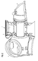
FIG 1 shows a wind turbine with a plain bearing. -
FIG 1 shows a longitudinal cut through thehub 2, the plain bearing 1 and theelectrical generator 7 of a direct driven wind turbine. The longitudinal cut is going along the axis of rotation of theelectrical generator 7 of the wind turbine. - The
hub 2 is connected to therotor 3 of the generator and to the rotating side of the bearing 1. Thestator 4 of thegenerator 7 is connected to the stationary side of the plains bearing 1. - The plain bearing 1 is located between the
hub 2 of the wind turbine and theelectrical generator 7 of the wind turbine. So it is connected with the stationary side to the hub-sided end of thestator 4 of thegenerator 7 and with the rotating side to thehub 2 of the wind turbine. - The plain bearing 1 is a tapered bearing. The cut through the bearing shows a V-shaped arrangement of two sliding
surfaces electrical generator 7. - The bearing
surface surface - The segments can be tilting pads. The surface of the tilting pads is capable to be aligned to the
bearing surface - The plain bearing 1 connects the rotating drive train of the wind turbine with the stationary part of the wind turbine in a rotatable manner.
- The rotating drive train comprises the
hub 2 of the wind turbine that is connected to therotor 3 of theelectrical generator 7. The stationary part of the wind turbine comprises thestator 4 of theelectrical generator 7. The bearing connects the rotating drive train of the wind turbine and therotor 3 of theelectrical generator 7 with thestator 4 of theelectrical generator 7. - The plain bearing 1 is constructed to bear the radial and axial forces and the bending moments present in the drive train. In this example there is only one bearing 1, with two sliding
surfaces -
FIG 2 shows a second configuration of the plain bearing. -
Fig 2 shows a cut along the axis of rotation of theelectrical generator 7. The cut shows thehub 2 of the wind turbine, therotor 3 and thestator 4 of theelectrical generator 7, the plain bearing 1 and aload bearing structure 8 that connects the stationary part of the wind turbine to the tower. - The plain bearing 1 is a tapered bearing and shows a tilted sliding
surface 5a. The first plain bearing 1 is combined with a second bearing 11. The second bearing 11 is a plain bearing that is located at the second end of theelectrical generator 7. - The second end of the
electrical generator 7 is the end opposite the end where the first bearing 1 is located. Opposite ends of theelectrical generator 7 are seen in respect to the axis of rotation of the generator. - The second bearing 11 is a tapered bearing with a tilted
bearing surface 5b. In this case the bearing surfaces 5a of the first bearing 1 and the slidingsurface 5b of the second bearing 11 are reversely sloped in axial direction in respect to the axis of rotation of the generator. - The second bearing 11 can also be a plain bearing with a cylindrical bearing surface.
- The first plain bearing 1 and the second plain bearing 11 are constructed to bear the radial and axial forces and the bending moments present in the drive train of the wind turbine.
-
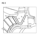
FIG 3 shows a detail of a configuration. -
FIG 3 shows an axial cut through the plain bearing 1 in the wind turbine. The plain bearing 1 is a tapered bearing and comprises two slidingsurfaces - The sliding
surfaces surfaces - The segments 6 can be tilting pads, which have a surface that is capable to be aligned to the
bearing surface - The segments of the sliding
surface -
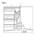
FIG 4 shows a detail of a plain bearing. -
FIG 4 shows a cut along the axis of rotation through thesecond bearing 9. Thesecond bearing 9 is arranged at the end of theelectrical generator 7 that is opposite of the end where the first plain bearing is located. - The
second bearing 9 is located between therotor 3 and thestator 4 of theelectrical generator 7. Thestator 4 is connected to the stationary part of the wind turbine. Thestator 4 of theelectrical generator 7 and the stationary part of the wind turbine are connected to theload bearing structure 8 that connects the stationary part of the wind turbine to the tower. - In this configuration the
second bearing 9 is a plain bearing with a slidingsurface 10. The sliding surface can be equipped with segments that are arranged and connected to build the slidingsurface 10 of thesecond bearing 9. The segments can be connected to the rotating part of thesecond bearing 9 or to the stationary part of thesecond bearing 9. - The segment can also be tilting pads that comprise a sliding
surface 10 that is capable to be aligned to the bearing surface of the counter side of thebearing 9, which is sliding along the pads when the bearing 1 is rotating. - In this configuration the
second bearing 9 shows a cylindrical bearing surface. Acylindrical bearing surface 10 is preferably combined with a tapered bearing as a first bearing at the opposite side of theelectrical generator 7. - The first bearing and the
second bearing 9 are constructed in a way to bear the radial and axial forces and the bending moments present in the drive train of the wind turbine.
Claims (10)
- Direct-drive wind turbine,- wherein a rotor of the wind turbine is directly connected with a rotating drive train of the wind turbine,- wherein the rotating drive train is directly connected with a rotor of a electrical generator (7) of the wind turbine,- wherein the rotating drive train is connected with a stationary part of the wind turbine via at least one bearing (1), which allows the rotation of the drive train in relation to the stationary part,- wherein the at least one bearing is a plain bearing,- wherein the bearing (1) is a tapered bearing, which comprises at least one conical shaped sliding surface,- wherein the bearing (1) comprises a segmented sliding-surface (5a, 5b),characterized in that- the segments (6) of the sliding-surface (5a, 5b) are arranged at a rotating part of the bearing, which is connected to the rotating drive train of the wind turbine,- wherein the segments (6) are arranged and connected within the plain bearing in a way that the exchange of an individual segment is permitted.
- Direct-drive wind turbine according to claim 1, wherein the bearing (1) comprises a first conical shaped sliding surface (5a) and a second conical shaped sliding surface (5b) which are reversely sloped in the axial direction of the plain bearing.
- Direct-drive wind turbine according to one of the preceding claims, wherein the bearing (1) connects as a first bearing the rotor (3) and the stator (4) of the wind turbine generator (7) and where the first bearing is located at a first end of the generator in respect to the axis of rotation of the generator (7).
- Direct-drive wind turbine according to one of the preceding claims, wherein a second bearing (11, 9) is arranged at a second end of the generator (7) in respect to the axis of rotation of the generator (7).
- Direct-drive wind turbine according to one of the preceding claims, wherein the second bearing (9) comprises a cylindrical bearing surface (10), which is prepared to support radial loads and bending moments of the drive train.
- Direct-drive wind turbine according to one of the preceding claims, wherein the segment (6) comprises at least one tipping pad, while the surface of the tipping pad is capable to be aligned to the bearing surface of the counter side of the bearing.
- Direct-drive wind turbine according to one of the preceding claims, wherein the bearing (1) is a hydrodynamic bearing, where a lubrication film at the sliding surface is maintained by the rotating bearing parts.
- Direct-drive wind turbine according to one of the claims 1 to 6, wherein the bearing (1) is a hydrostatic bearing, where a lubrication film at the sliding surface is maintained by an applied pressure of an external pump.
- Direct-drive wind turbine according to one of the claims 1 to 6, wherein the bearing (1) is a hybrid bearing, where a lubrication film at the sliding surface is maintained by a combination of an applied pressure of an external pump and by rotating bearing parts.
- Direct-drive wind turbine according to one of the preceding claims, wherein the sliding surface (5a, 5b) of the plain bearing (1) comprises a groove and/or a pocket, being used as inlet or outlet for lubrication purposes of the plain bearing (1).
Priority Applications (1)
| Application Number | Priority Date | Filing Date | Title |
|---|---|---|---|
| EP12748188.5A EP2694810B2 (en) | 2011-09-08 | 2012-08-10 | Direct-drive wind turbine |
Applications Claiming Priority (3)
| Application Number | Priority Date | Filing Date | Title |
|---|---|---|---|
| EP11180622A EP2568168A1 (en) | 2011-09-08 | 2011-09-08 | Direct-drive wind turbine |
| PCT/EP2012/065673 WO2013034389A2 (en) | 2011-09-08 | 2012-08-10 | Direct-drive wind turbine |
| EP12748188.5A EP2694810B2 (en) | 2011-09-08 | 2012-08-10 | Direct-drive wind turbine |
Publications (3)
| Publication Number | Publication Date |
|---|---|
| EP2694810A2 EP2694810A2 (en) | 2014-02-12 |
| EP2694810B1 true EP2694810B1 (en) | 2015-11-25 |
| EP2694810B2 EP2694810B2 (en) | 2019-04-10 |
Family
ID=46690489
Family Applications (2)
| Application Number | Title | Priority Date | Filing Date |
|---|---|---|---|
| EP11180622A Withdrawn EP2568168A1 (en) | 2011-09-08 | 2011-09-08 | Direct-drive wind turbine |
| EP12748188.5A Active EP2694810B2 (en) | 2011-09-08 | 2012-08-10 | Direct-drive wind turbine |
Family Applications Before (1)
| Application Number | Title | Priority Date | Filing Date |
|---|---|---|---|
| EP11180622A Withdrawn EP2568168A1 (en) | 2011-09-08 | 2011-09-08 | Direct-drive wind turbine |
Country Status (5)
| Country | Link |
|---|---|
| US (1) | US9797378B2 (en) |
| EP (2) | EP2568168A1 (en) |
| CN (1) | CN103782028B (en) |
| DK (1) | DK2694810T4 (en) |
| WO (1) | WO2013034389A2 (en) |
Cited By (1)
| Publication number | Priority date | Publication date | Assignee | Title |
|---|---|---|---|---|
| DE102020112765A1 (en) | 2020-05-12 | 2021-11-18 | Miba Gleitlager Austria Gmbh | Main rotor bearing of a nacelle for a wind turbine |
Families Citing this family (24)
| Publication number | Priority date | Publication date | Assignee | Title |
|---|---|---|---|---|
| DK2626577T3 (en) * | 2012-02-10 | 2019-02-04 | Siemens Ag | Method for controlling a wind turbine and wind turbine |
| WO2013191163A1 (en) | 2012-06-19 | 2013-12-27 | 富士電機株式会社 | Composite sliding bearing and wind-powered electricity generation device using this bearing |
| DK2949921T3 (en) | 2014-05-28 | 2019-04-23 | Siemens Ag | Rotor hub for a wind turbine |
| DK3130802T3 (en) * | 2015-08-11 | 2020-01-02 | Siemens Gamesa Renewable Energy As | Reinforced main bearing of a wind turbine |
| EP3219984B1 (en) * | 2016-03-14 | 2019-01-02 | Siemens Aktiengesellschaft | Sliding bearing arrangement for a wind turbine |
| TWI597436B (en) | 2016-03-15 | 2017-09-01 | 財團法人工業技術研究院 | Hydrostatic bearing |
| DE102016209206A1 (en) * | 2016-05-27 | 2017-12-14 | Wobben Properties Gmbh | Wind turbine |
| DE102016210039A1 (en) | 2016-06-07 | 2017-12-07 | Wobben Properties Gmbh | Wind turbine rotary joint, rotor blade and wind turbine with selbiger |
| EP3276192B1 (en) * | 2016-07-29 | 2019-11-27 | Siemens Gamesa Renewable Energy A/S | Bearing arrangement |
| DE102017105577A1 (en) * | 2017-03-15 | 2018-09-20 | Thyssenkrupp Ag | Bearing arrangement and wind turbine |
| EP3460238B1 (en) * | 2017-09-20 | 2020-04-15 | Siemens Gamesa Renewable Energy A/S | Wind turbine |
| DE102017223370A1 (en) | 2017-12-20 | 2019-06-27 | Zf Friedrichshafen Ag | Adjustable slide bearing |
| DE102018120810A1 (en) * | 2018-08-27 | 2020-02-27 | Renk Aktiengesellschaft | Bearing arrangement of a rotor of a wind turbine and wind turbine |
| DE102018120806A1 (en) * | 2018-08-27 | 2020-02-27 | Renk Aktiengesellschaft | Bearing arrangement of a rotor of a wind turbine |
| AT521775B1 (en) | 2018-12-13 | 2020-06-15 | Miba Gleitlager Austria Gmbh | Planetary gear for a wind turbine |
| AT521882B1 (en) | 2018-12-13 | 2021-05-15 | Miba Gleitlager Austria Gmbh | Plain bearings, in particular for a gearbox of a wind turbine |
| AT521884B1 (en) | 2018-12-13 | 2020-10-15 | Miba Gleitlager Austria Gmbh | Method for changing a slide bearing element of a rotor bearing of a wind turbine, as well as a nacelle for a wind turbine |
| AT521687B1 (en) * | 2018-12-13 | 2020-04-15 | Miba Gleitlager Austria Gmbh | Gondola for a wind turbine |
| AT522155B1 (en) * | 2019-03-07 | 2020-09-15 | Miba Gleitlager Austria Gmbh | Plain bearing |
| US11174895B2 (en) | 2019-04-30 | 2021-11-16 | General Electric Company | Bearing for a wind turbine drivetrain having an elastomer support |
| EP3739226B1 (en) * | 2019-05-16 | 2022-12-14 | Siemens Gamesa Renewable Energy A/S | Bearing arrangement for a wind turbine and wind turbine |
| CN110566417B (en) * | 2019-09-12 | 2020-11-24 | 上海电气风电集团股份有限公司 | Sliding main bearing drive chain and double-fed wind turbine comprising same |
| EP3904712A1 (en) * | 2020-04-28 | 2021-11-03 | Siemens Gamesa Renewable Energy A/S | Main bearing for a wind turbine |
| CN112664401B (en) * | 2020-12-28 | 2023-01-20 | 诸暨和创磁电科技有限公司 | Wind driven generator for realizing stable power output based on combination of rotary table and rotary shaft |
Citations (5)
| Publication number | Priority date | Publication date | Assignee | Title |
|---|---|---|---|---|
| DE2409711C2 (en) | 1973-02-28 | 1983-08-25 | The Glacier Metal Co. Ltd., Alperton, Wembley, Middlesex | Axial tilting pad plain bearings |
| WO2001048376A2 (en) | 1999-12-24 | 2001-07-05 | Aloys Wobben | Plain bearing and wind energy unit with said bearing |
| EP1184567A2 (en) | 2000-09-01 | 2002-03-06 | Renk Aktiengesellschaft | Gearbox for wind turbines |
| DE10255745A1 (en) | 2002-11-28 | 2004-06-17 | Jörck, Hartmut | Directly driven wind power system with bearing integrated in generator has generator rotor or hub radially between and/or axially adjacent to generator stator and rotor and supported on stator housing |
| WO2011127510A1 (en) | 2010-04-14 | 2011-10-20 | Miba Gleitlager Gmbh | Bearing element |
Family Cites Families (3)
| Publication number | Priority date | Publication date | Assignee | Title |
|---|---|---|---|---|
| NL2001190C1 (en) * | 2008-01-16 | 2009-07-20 | Lagerwey Wind B V | Generator for a direct-driven wind turbine. |
| EP2164154A1 (en) * | 2008-09-15 | 2010-03-17 | Siemens Aktiengesellschaft | Stator arrangement, generator and wind turbine |
| US9297363B2 (en) | 2009-07-10 | 2016-03-29 | Siemens Aktiengesellschaft | Wind turbine main bearing |
-
2011
- 2011-09-08 EP EP11180622A patent/EP2568168A1/en not_active Withdrawn
-
2012
- 2012-08-10 WO PCT/EP2012/065673 patent/WO2013034389A2/en active Application Filing
- 2012-08-10 CN CN201280043763.3A patent/CN103782028B/en active Active
- 2012-08-10 EP EP12748188.5A patent/EP2694810B2/en active Active
- 2012-08-10 DK DK12748188.5T patent/DK2694810T4/en active
- 2012-08-10 US US14/122,119 patent/US9797378B2/en active Active
Patent Citations (5)
| Publication number | Priority date | Publication date | Assignee | Title |
|---|---|---|---|---|
| DE2409711C2 (en) | 1973-02-28 | 1983-08-25 | The Glacier Metal Co. Ltd., Alperton, Wembley, Middlesex | Axial tilting pad plain bearings |
| WO2001048376A2 (en) | 1999-12-24 | 2001-07-05 | Aloys Wobben | Plain bearing and wind energy unit with said bearing |
| EP1184567A2 (en) | 2000-09-01 | 2002-03-06 | Renk Aktiengesellschaft | Gearbox for wind turbines |
| DE10255745A1 (en) | 2002-11-28 | 2004-06-17 | Jörck, Hartmut | Directly driven wind power system with bearing integrated in generator has generator rotor or hub radially between and/or axially adjacent to generator stator and rotor and supported on stator housing |
| WO2011127510A1 (en) | 2010-04-14 | 2011-10-20 | Miba Gleitlager Gmbh | Bearing element |
Non-Patent Citations (4)
| Title |
|---|
| EMAIL VON HERRN KARI, 29 November 2010 (2010-11-29) |
| NDA SIEMENS/MIBA |
| WIND ENERGY - OVERVIEW - POTENTIAL, COMPETENCES & EXPERIENCE, October 2010 (2010-10-01) |
| WIND ENERGY - PLAIN BEARINGS IN MAIN BEARING APPLICATIONS, September 2010 (2010-09-01) |
Cited By (3)
| Publication number | Priority date | Publication date | Assignee | Title |
|---|---|---|---|---|
| DE102020112765A1 (en) | 2020-05-12 | 2021-11-18 | Miba Gleitlager Austria Gmbh | Main rotor bearing of a nacelle for a wind turbine |
| WO2021226645A1 (en) | 2020-05-12 | 2021-11-18 | Miba Gleitlager Austria Gmbh | Rotor main bearing of a nacelle for a wind turbine |
| US11873858B2 (en) | 2020-05-12 | 2024-01-16 | Miba Gleitlager Austria Gmbh | Rotor main bearing of a nacelle for a wind turbine |
Also Published As
| Publication number | Publication date |
|---|---|
| EP2568168A1 (en) | 2013-03-13 |
| DK2694810T4 (en) | 2019-07-15 |
| CN103782028B (en) | 2017-05-24 |
| US20140169952A1 (en) | 2014-06-19 |
| CN103782028A (en) | 2014-05-07 |
| EP2694810B2 (en) | 2019-04-10 |
| WO2013034389A2 (en) | 2013-03-14 |
| US9797378B2 (en) | 2017-10-24 |
| WO2013034389A3 (en) | 2013-10-10 |
| EP2694810A2 (en) | 2014-02-12 |
| DK2694810T3 (en) | 2016-02-22 |
Similar Documents
| Publication | Publication Date | Title |
|---|---|---|
| EP2694810B2 (en) | Direct-drive wind turbine | |
| EP2568167A1 (en) | Direct-drive wind turbine | |
| DK2816226T3 (en) | Wind turbine with a slip bearing | |
| JP5650210B2 (en) | Wind turbine main bearing | |
| EP3219984B1 (en) | Sliding bearing arrangement for a wind turbine | |
| EP3460238B1 (en) | Wind turbine | |
| US9458880B2 (en) | Bearing element for supporting the rotor hub of a wind turbine | |
| US8021101B2 (en) | Wind turbine and method of assembling the same | |
| EP2669538B1 (en) | Journal pad bearing for turbine | |
| US8936397B2 (en) | Sliding bearing and method to perform service at a sliding bearing | |
| CN103967936B (en) | The collection method of bearing and the lubricant gone out from bearing leakage | |
| US11592008B2 (en) | Fluid film bearing and wind turbine | |
| JP5932058B2 (en) | Wind power generator | |
| EP3988807A1 (en) | Spherical journal bearing for a wind turbine drivetrain | |
| CN105074204A (en) | A hub and bearing system and a turbine comprising the hub and bearing system |
Legal Events
| Date | Code | Title | Description |
|---|---|---|---|
| PUAI | Public reference made under article 153(3) epc to a published international application that has entered the european phase |
Free format text: ORIGINAL CODE: 0009012 |
|
| 17P | Request for examination filed |
Effective date: 20131106 |
|
| AK | Designated contracting states |
Kind code of ref document: A2 Designated state(s): AL AT BE BG CH CY CZ DE DK EE ES FI FR GB GR HR HU IE IS IT LI LT LU LV MC MK MT NL NO PL PT RO RS SE SI SK SM TR |
|
| DAX | Request for extension of the european patent (deleted) | ||
| REG | Reference to a national code |
Ref country code: DE Ref legal event code: R079 Ref document number: 602012012673 Country of ref document: DE Free format text: PREVIOUS MAIN CLASS: F03D0011000000 Ipc: F03D0009000000 |
|
| RIC1 | Information provided on ipc code assigned before grant |
Ipc: F03D 11/02 20060101ALI20150505BHEP Ipc: F16C 17/10 20060101ALI20150505BHEP Ipc: F03D 9/00 20060101AFI20150505BHEP Ipc: F16C 17/03 20060101ALI20150505BHEP Ipc: F03D 11/00 20060101ALI20150505BHEP Ipc: F16C 17/06 20060101ALI20150505BHEP |
|
| GRAP | Despatch of communication of intention to grant a patent |
Free format text: ORIGINAL CODE: EPIDOSNIGR1 |
|
| INTG | Intention to grant announced |
Effective date: 20150616 |
|
| GRAS | Grant fee paid |
Free format text: ORIGINAL CODE: EPIDOSNIGR3 |
|
| GRAA | (expected) grant |
Free format text: ORIGINAL CODE: 0009210 |
|
| AK | Designated contracting states |
Kind code of ref document: B1 Designated state(s): AL AT BE BG CH CY CZ DE DK EE ES FI FR GB GR HR HU IE IS IT LI LT LU LV MC MK MT NL NO PL PT RO RS SE SI SK SM TR |
|
| REG | Reference to a national code |
Ref country code: GB Ref legal event code: FG4D |
|
| REG | Reference to a national code |
Ref country code: CH Ref legal event code: EP |
|
| REG | Reference to a national code |
Ref country code: AT Ref legal event code: REF Ref document number: 762769 Country of ref document: AT Kind code of ref document: T Effective date: 20151215 |
|
| REG | Reference to a national code |
Ref country code: IE Ref legal event code: FG4D |
|
| REG | Reference to a national code |
Ref country code: DE Ref legal event code: R096 Ref document number: 602012012673 Country of ref document: DE |
|
| REG | Reference to a national code |
Ref country code: DK Ref legal event code: T3 Effective date: 20160216 |
|
| REG | Reference to a national code |
Ref country code: LT Ref legal event code: MG4D |
|
| REG | Reference to a national code |
Ref country code: NL Ref legal event code: MP Effective date: 20160225 |
|
| REG | Reference to a national code |
Ref country code: AT Ref legal event code: MK05 Ref document number: 762769 Country of ref document: AT Kind code of ref document: T Effective date: 20151125 |
|
| PG25 | Lapsed in a contracting state [announced via postgrant information from national office to epo] |
Ref country code: IS Free format text: LAPSE BECAUSE OF FAILURE TO SUBMIT A TRANSLATION OF THE DESCRIPTION OR TO PAY THE FEE WITHIN THE PRESCRIBED TIME-LIMIT Effective date: 20160325 Ref country code: HR Free format text: LAPSE BECAUSE OF FAILURE TO SUBMIT A TRANSLATION OF THE DESCRIPTION OR TO PAY THE FEE WITHIN THE PRESCRIBED TIME-LIMIT Effective date: 20151125 Ref country code: ES Free format text: LAPSE BECAUSE OF FAILURE TO SUBMIT A TRANSLATION OF THE DESCRIPTION OR TO PAY THE FEE WITHIN THE PRESCRIBED TIME-LIMIT Effective date: 20151125 Ref country code: LT Free format text: LAPSE BECAUSE OF FAILURE TO SUBMIT A TRANSLATION OF THE DESCRIPTION OR TO PAY THE FEE WITHIN THE PRESCRIBED TIME-LIMIT Effective date: 20151125 Ref country code: NO Free format text: LAPSE BECAUSE OF FAILURE TO SUBMIT A TRANSLATION OF THE DESCRIPTION OR TO PAY THE FEE WITHIN THE PRESCRIBED TIME-LIMIT Effective date: 20160225 Ref country code: NL Free format text: LAPSE BECAUSE OF FAILURE TO SUBMIT A TRANSLATION OF THE DESCRIPTION OR TO PAY THE FEE WITHIN THE PRESCRIBED TIME-LIMIT Effective date: 20151125 |
|
| PG25 | Lapsed in a contracting state [announced via postgrant information from national office to epo] |
Ref country code: AT Free format text: LAPSE BECAUSE OF FAILURE TO SUBMIT A TRANSLATION OF THE DESCRIPTION OR TO PAY THE FEE WITHIN THE PRESCRIBED TIME-LIMIT Effective date: 20151125 Ref country code: GR Free format text: LAPSE BECAUSE OF FAILURE TO SUBMIT A TRANSLATION OF THE DESCRIPTION OR TO PAY THE FEE WITHIN THE PRESCRIBED TIME-LIMIT Effective date: 20160226 Ref country code: LV Free format text: LAPSE BECAUSE OF FAILURE TO SUBMIT A TRANSLATION OF THE DESCRIPTION OR TO PAY THE FEE WITHIN THE PRESCRIBED TIME-LIMIT Effective date: 20151125 Ref country code: PL Free format text: LAPSE BECAUSE OF FAILURE TO SUBMIT A TRANSLATION OF THE DESCRIPTION OR TO PAY THE FEE WITHIN THE PRESCRIBED TIME-LIMIT Effective date: 20151125 Ref country code: SE Free format text: LAPSE BECAUSE OF FAILURE TO SUBMIT A TRANSLATION OF THE DESCRIPTION OR TO PAY THE FEE WITHIN THE PRESCRIBED TIME-LIMIT Effective date: 20151125 Ref country code: PT Free format text: LAPSE BECAUSE OF FAILURE TO SUBMIT A TRANSLATION OF THE DESCRIPTION OR TO PAY THE FEE WITHIN THE PRESCRIBED TIME-LIMIT Effective date: 20160325 Ref country code: FI Free format text: LAPSE BECAUSE OF FAILURE TO SUBMIT A TRANSLATION OF THE DESCRIPTION OR TO PAY THE FEE WITHIN THE PRESCRIBED TIME-LIMIT Effective date: 20151125 Ref country code: RS Free format text: LAPSE BECAUSE OF FAILURE TO SUBMIT A TRANSLATION OF THE DESCRIPTION OR TO PAY THE FEE WITHIN THE PRESCRIBED TIME-LIMIT Effective date: 20151125 |
|
| REG | Reference to a national code |
Ref country code: DE Ref legal event code: R026 Ref document number: 602012012673 Country of ref document: DE |
|
| PLBI | Opposition filed |
Free format text: ORIGINAL CODE: 0009260 |
|
| PG25 | Lapsed in a contracting state [announced via postgrant information from national office to epo] |
Ref country code: CZ Free format text: LAPSE BECAUSE OF FAILURE TO SUBMIT A TRANSLATION OF THE DESCRIPTION OR TO PAY THE FEE WITHIN THE PRESCRIBED TIME-LIMIT Effective date: 20151125 Ref country code: IT Free format text: LAPSE BECAUSE OF FAILURE TO SUBMIT A TRANSLATION OF THE DESCRIPTION OR TO PAY THE FEE WITHIN THE PRESCRIBED TIME-LIMIT Effective date: 20151125 |
|
| 26 | Opposition filed |
Opponent name: MIBA GLEITLAGE AUSTRIA GMBH Effective date: 20160630 |
|
| REG | Reference to a national code |
Ref country code: FR Ref legal event code: PLFP Year of fee payment: 5 |
|
| PG25 | Lapsed in a contracting state [announced via postgrant information from national office to epo] |
Ref country code: EE Free format text: LAPSE BECAUSE OF FAILURE TO SUBMIT A TRANSLATION OF THE DESCRIPTION OR TO PAY THE FEE WITHIN THE PRESCRIBED TIME-LIMIT Effective date: 20151125 Ref country code: SK Free format text: LAPSE BECAUSE OF FAILURE TO SUBMIT A TRANSLATION OF THE DESCRIPTION OR TO PAY THE FEE WITHIN THE PRESCRIBED TIME-LIMIT Effective date: 20151125 Ref country code: RO Free format text: LAPSE BECAUSE OF FAILURE TO SUBMIT A TRANSLATION OF THE DESCRIPTION OR TO PAY THE FEE WITHIN THE PRESCRIBED TIME-LIMIT Effective date: 20151125 Ref country code: SM Free format text: LAPSE BECAUSE OF FAILURE TO SUBMIT A TRANSLATION OF THE DESCRIPTION OR TO PAY THE FEE WITHIN THE PRESCRIBED TIME-LIMIT Effective date: 20151125 |
|
| PLAX | Notice of opposition and request to file observation + time limit sent |
Free format text: ORIGINAL CODE: EPIDOSNOBS2 |
|
| PG25 | Lapsed in a contracting state [announced via postgrant information from national office to epo] |
Ref country code: SI Free format text: LAPSE BECAUSE OF FAILURE TO SUBMIT A TRANSLATION OF THE DESCRIPTION OR TO PAY THE FEE WITHIN THE PRESCRIBED TIME-LIMIT Effective date: 20151125 |
|
| PG25 | Lapsed in a contracting state [announced via postgrant information from national office to epo] |
Ref country code: BE Free format text: LAPSE BECAUSE OF FAILURE TO SUBMIT A TRANSLATION OF THE DESCRIPTION OR TO PAY THE FEE WITHIN THE PRESCRIBED TIME-LIMIT Effective date: 20151125 |
|
| PLBB | Reply of patent proprietor to notice(s) of opposition received |
Free format text: ORIGINAL CODE: EPIDOSNOBS3 |
|
| PG25 | Lapsed in a contracting state [announced via postgrant information from national office to epo] |
Ref country code: MC Free format text: LAPSE BECAUSE OF FAILURE TO SUBMIT A TRANSLATION OF THE DESCRIPTION OR TO PAY THE FEE WITHIN THE PRESCRIBED TIME-LIMIT Effective date: 20151125 |
|
| REG | Reference to a national code |
Ref country code: CH Ref legal event code: PL |
|
| PG25 | Lapsed in a contracting state [announced via postgrant information from national office to epo] |
Ref country code: LI Free format text: LAPSE BECAUSE OF NON-PAYMENT OF DUE FEES Effective date: 20160831 Ref country code: CH Free format text: LAPSE BECAUSE OF NON-PAYMENT OF DUE FEES Effective date: 20160831 |
|
| REG | Reference to a national code |
Ref country code: IE Ref legal event code: MM4A |
|
| PG25 | Lapsed in a contracting state [announced via postgrant information from national office to epo] |
Ref country code: IE Free format text: LAPSE BECAUSE OF NON-PAYMENT OF DUE FEES Effective date: 20160810 |
|
| REG | Reference to a national code |
Ref country code: FR Ref legal event code: PLFP Year of fee payment: 6 |
|
| RAP2 | Party data changed (patent owner data changed or rights of a patent transferred) |
Owner name: SIEMENS AKTIENGESELLSCHAFT |
|
| PG25 | Lapsed in a contracting state [announced via postgrant information from national office to epo] |
Ref country code: LU Free format text: LAPSE BECAUSE OF NON-PAYMENT OF DUE FEES Effective date: 20160810 |
|
| PG25 | Lapsed in a contracting state [announced via postgrant information from national office to epo] |
Ref country code: CY Free format text: LAPSE BECAUSE OF FAILURE TO SUBMIT A TRANSLATION OF THE DESCRIPTION OR TO PAY THE FEE WITHIN THE PRESCRIBED TIME-LIMIT Effective date: 20151125 Ref country code: HU Free format text: LAPSE BECAUSE OF FAILURE TO SUBMIT A TRANSLATION OF THE DESCRIPTION OR TO PAY THE FEE WITHIN THE PRESCRIBED TIME-LIMIT; INVALID AB INITIO Effective date: 20120810 |
|
| PG25 | Lapsed in a contracting state [announced via postgrant information from national office to epo] |
Ref country code: MK Free format text: LAPSE BECAUSE OF FAILURE TO SUBMIT A TRANSLATION OF THE DESCRIPTION OR TO PAY THE FEE WITHIN THE PRESCRIBED TIME-LIMIT Effective date: 20151125 Ref country code: TR Free format text: LAPSE BECAUSE OF FAILURE TO SUBMIT A TRANSLATION OF THE DESCRIPTION OR TO PAY THE FEE WITHIN THE PRESCRIBED TIME-LIMIT Effective date: 20151125 Ref country code: MT Free format text: LAPSE BECAUSE OF NON-PAYMENT OF DUE FEES Effective date: 20160831 |
|
| PG25 | Lapsed in a contracting state [announced via postgrant information from national office to epo] |
Ref country code: BG Free format text: LAPSE BECAUSE OF FAILURE TO SUBMIT A TRANSLATION OF THE DESCRIPTION OR TO PAY THE FEE WITHIN THE PRESCRIBED TIME-LIMIT Effective date: 20151125 |
|
| REG | Reference to a national code |
Ref country code: FR Ref legal event code: PLFP Year of fee payment: 7 |
|
| PG25 | Lapsed in a contracting state [announced via postgrant information from national office to epo] |
Ref country code: AL Free format text: LAPSE BECAUSE OF FAILURE TO SUBMIT A TRANSLATION OF THE DESCRIPTION OR TO PAY THE FEE WITHIN THE PRESCRIBED TIME-LIMIT Effective date: 20151125 |
|
| PUAH | Patent maintained in amended form |
Free format text: ORIGINAL CODE: 0009272 |
|
| STAA | Information on the status of an ep patent application or granted ep patent |
Free format text: STATUS: PATENT MAINTAINED AS AMENDED |
|
| 27A | Patent maintained in amended form |
Effective date: 20190410 |
|
| AK | Designated contracting states |
Kind code of ref document: B2 Designated state(s): AL AT BE BG CH CY CZ DE DK EE ES FI FR GB GR HR HU IE IS IT LI LT LU LV MC MK MT NL NO PL PT RO RS SE SI SK SM TR |
|
| REG | Reference to a national code |
Ref country code: DE Ref legal event code: R102 Ref document number: 602012012673 Country of ref document: DE |
|
| REG | Reference to a national code |
Ref country code: DK Ref legal event code: T4 Effective date: 20190711 |
|
| REG | Reference to a national code |
Ref country code: DE Ref legal event code: R081 Ref document number: 602012012673 Country of ref document: DE Owner name: SIEMENS GAMESA RENEWABLE ENERGY A/S, DK Free format text: FORMER OWNER: SIEMENS AKTIENGESELLSCHAFT, 80333 MUENCHEN, DE |
|
| REG | Reference to a national code |
Ref country code: GB Ref legal event code: 732E Free format text: REGISTERED BETWEEN 20191128 AND 20191204 |
|
| P01 | Opt-out of the competence of the unified patent court (upc) registered |
Effective date: 20230530 |
|
| PGFP | Annual fee paid to national office [announced via postgrant information from national office to epo] |
Ref country code: GB Payment date: 20230824 Year of fee payment: 12 |
|
| PGFP | Annual fee paid to national office [announced via postgrant information from national office to epo] |
Ref country code: FR Payment date: 20230821 Year of fee payment: 12 Ref country code: DK Payment date: 20230823 Year of fee payment: 12 Ref country code: DE Payment date: 20230822 Year of fee payment: 12 |