EP3276192B1 - Bearing arrangement - Google Patents
Bearing arrangement Download PDFInfo
- Publication number
- EP3276192B1 EP3276192B1 EP16181950.3A EP16181950A EP3276192B1 EP 3276192 B1 EP3276192 B1 EP 3276192B1 EP 16181950 A EP16181950 A EP 16181950A EP 3276192 B1 EP3276192 B1 EP 3276192B1
- Authority
- EP
- European Patent Office
- Prior art keywords
- bearing
- drive shaft
- pads
- arrangement according
- bearing arrangement
- Prior art date
- Legal status (The legal status is an assumption and is not a legal conclusion. Google has not performed a legal analysis and makes no representation as to the accuracy of the status listed.)
- Active
Links
- 239000012530 fluid Substances 0.000 claims description 25
- 238000009826 distribution Methods 0.000 claims description 23
- 238000012546 transfer Methods 0.000 claims description 4
- 230000001419 dependent effect Effects 0.000 claims description 2
- 238000010586 diagram Methods 0.000 description 9
- 238000013461 design Methods 0.000 description 4
- 230000002349 favourable effect Effects 0.000 description 2
- 239000010408 film Substances 0.000 description 2
- 238000012423 maintenance Methods 0.000 description 2
- 238000010276 construction Methods 0.000 description 1
- 238000000034 method Methods 0.000 description 1
- 238000012986 modification Methods 0.000 description 1
- 230000004048 modification Effects 0.000 description 1
- 238000003825 pressing Methods 0.000 description 1
- 239000010409 thin film Substances 0.000 description 1
- 238000009827 uniform distribution Methods 0.000 description 1
Images
Classifications
-
- F—MECHANICAL ENGINEERING; LIGHTING; HEATING; WEAPONS; BLASTING
- F16—ENGINEERING ELEMENTS AND UNITS; GENERAL MEASURES FOR PRODUCING AND MAINTAINING EFFECTIVE FUNCTIONING OF MACHINES OR INSTALLATIONS; THERMAL INSULATION IN GENERAL
- F16C—SHAFTS; FLEXIBLE SHAFTS; ELEMENTS OR CRANKSHAFT MECHANISMS; ROTARY BODIES OTHER THAN GEARING ELEMENTS; BEARINGS
- F16C35/00—Rigid support of bearing units; Housings, e.g. caps, covers
- F16C35/02—Rigid support of bearing units; Housings, e.g. caps, covers in the case of sliding-contact bearings
-
- F—MECHANICAL ENGINEERING; LIGHTING; HEATING; WEAPONS; BLASTING
- F03—MACHINES OR ENGINES FOR LIQUIDS; WIND, SPRING, OR WEIGHT MOTORS; PRODUCING MECHANICAL POWER OR A REACTIVE PROPULSIVE THRUST, NOT OTHERWISE PROVIDED FOR
- F03D—WIND MOTORS
- F03D80/00—Details, components or accessories not provided for in groups F03D1/00 - F03D17/00
- F03D80/70—Bearing or lubricating arrangements
-
- F—MECHANICAL ENGINEERING; LIGHTING; HEATING; WEAPONS; BLASTING
- F16—ENGINEERING ELEMENTS AND UNITS; GENERAL MEASURES FOR PRODUCING AND MAINTAINING EFFECTIVE FUNCTIONING OF MACHINES OR INSTALLATIONS; THERMAL INSULATION IN GENERAL
- F16C—SHAFTS; FLEXIBLE SHAFTS; ELEMENTS OR CRANKSHAFT MECHANISMS; ROTARY BODIES OTHER THAN GEARING ELEMENTS; BEARINGS
- F16C17/00—Sliding-contact bearings for exclusively rotary movement
- F16C17/02—Sliding-contact bearings for exclusively rotary movement for radial load only
- F16C17/03—Sliding-contact bearings for exclusively rotary movement for radial load only with tiltably-supported segments, e.g. Michell bearings
-
- F—MECHANICAL ENGINEERING; LIGHTING; HEATING; WEAPONS; BLASTING
- F16—ENGINEERING ELEMENTS AND UNITS; GENERAL MEASURES FOR PRODUCING AND MAINTAINING EFFECTIVE FUNCTIONING OF MACHINES OR INSTALLATIONS; THERMAL INSULATION IN GENERAL
- F16C—SHAFTS; FLEXIBLE SHAFTS; ELEMENTS OR CRANKSHAFT MECHANISMS; ROTARY BODIES OTHER THAN GEARING ELEMENTS; BEARINGS
- F16C17/00—Sliding-contact bearings for exclusively rotary movement
- F16C17/12—Sliding-contact bearings for exclusively rotary movement characterised by features not related to the direction of the load
- F16C17/24—Sliding-contact bearings for exclusively rotary movement characterised by features not related to the direction of the load with devices affected by abnormal or undesired positions, e.g. for preventing overheating, for safety
- F16C17/246—Sliding-contact bearings for exclusively rotary movement characterised by features not related to the direction of the load with devices affected by abnormal or undesired positions, e.g. for preventing overheating, for safety related to wear, e.g. sensors for measuring wear
-
- F—MECHANICAL ENGINEERING; LIGHTING; HEATING; WEAPONS; BLASTING
- F16—ENGINEERING ELEMENTS AND UNITS; GENERAL MEASURES FOR PRODUCING AND MAINTAINING EFFECTIVE FUNCTIONING OF MACHINES OR INSTALLATIONS; THERMAL INSULATION IN GENERAL
- F16C—SHAFTS; FLEXIBLE SHAFTS; ELEMENTS OR CRANKSHAFT MECHANISMS; ROTARY BODIES OTHER THAN GEARING ELEMENTS; BEARINGS
- F16C17/00—Sliding-contact bearings for exclusively rotary movement
- F16C17/26—Systems consisting of a plurality of sliding-contact bearings
-
- F—MECHANICAL ENGINEERING; LIGHTING; HEATING; WEAPONS; BLASTING
- F16—ENGINEERING ELEMENTS AND UNITS; GENERAL MEASURES FOR PRODUCING AND MAINTAINING EFFECTIVE FUNCTIONING OF MACHINES OR INSTALLATIONS; THERMAL INSULATION IN GENERAL
- F16C—SHAFTS; FLEXIBLE SHAFTS; ELEMENTS OR CRANKSHAFT MECHANISMS; ROTARY BODIES OTHER THAN GEARING ELEMENTS; BEARINGS
- F16C41/00—Other accessories, e.g. devices integrated in the bearing not relating to the bearing function as such
- F16C41/02—Arrangements for equalising the load on a plurality of bearings or their elements
-
- F—MECHANICAL ENGINEERING; LIGHTING; HEATING; WEAPONS; BLASTING
- F05—INDEXING SCHEMES RELATING TO ENGINES OR PUMPS IN VARIOUS SUBCLASSES OF CLASSES F01-F04
- F05B—INDEXING SCHEME RELATING TO WIND, SPRING, WEIGHT, INERTIA OR LIKE MOTORS, TO MACHINES OR ENGINES FOR LIQUIDS COVERED BY SUBCLASSES F03B, F03D AND F03G
- F05B2240/00—Components
- F05B2240/50—Bearings
- F05B2240/53—Hydrodynamic or hydrostatic bearings
-
- F—MECHANICAL ENGINEERING; LIGHTING; HEATING; WEAPONS; BLASTING
- F05—INDEXING SCHEMES RELATING TO ENGINES OR PUMPS IN VARIOUS SUBCLASSES OF CLASSES F01-F04
- F05B—INDEXING SCHEME RELATING TO WIND, SPRING, WEIGHT, INERTIA OR LIKE MOTORS, TO MACHINES OR ENGINES FOR LIQUIDS COVERED BY SUBCLASSES F03B, F03D AND F03G
- F05B2240/00—Components
- F05B2240/60—Shafts
-
- F—MECHANICAL ENGINEERING; LIGHTING; HEATING; WEAPONS; BLASTING
- F16—ENGINEERING ELEMENTS AND UNITS; GENERAL MEASURES FOR PRODUCING AND MAINTAINING EFFECTIVE FUNCTIONING OF MACHINES OR INSTALLATIONS; THERMAL INSULATION IN GENERAL
- F16C—SHAFTS; FLEXIBLE SHAFTS; ELEMENTS OR CRANKSHAFT MECHANISMS; ROTARY BODIES OTHER THAN GEARING ELEMENTS; BEARINGS
- F16C2229/00—Setting preload
-
- F—MECHANICAL ENGINEERING; LIGHTING; HEATING; WEAPONS; BLASTING
- F16—ENGINEERING ELEMENTS AND UNITS; GENERAL MEASURES FOR PRODUCING AND MAINTAINING EFFECTIVE FUNCTIONING OF MACHINES OR INSTALLATIONS; THERMAL INSULATION IN GENERAL
- F16C—SHAFTS; FLEXIBLE SHAFTS; ELEMENTS OR CRANKSHAFT MECHANISMS; ROTARY BODIES OTHER THAN GEARING ELEMENTS; BEARINGS
- F16C2300/00—Application independent of particular apparatuses
- F16C2300/10—Application independent of particular apparatuses related to size
- F16C2300/14—Large applications, e.g. bearings having an inner diameter exceeding 500 mm
-
- F—MECHANICAL ENGINEERING; LIGHTING; HEATING; WEAPONS; BLASTING
- F16—ENGINEERING ELEMENTS AND UNITS; GENERAL MEASURES FOR PRODUCING AND MAINTAINING EFFECTIVE FUNCTIONING OF MACHINES OR INSTALLATIONS; THERMAL INSULATION IN GENERAL
- F16C—SHAFTS; FLEXIBLE SHAFTS; ELEMENTS OR CRANKSHAFT MECHANISMS; ROTARY BODIES OTHER THAN GEARING ELEMENTS; BEARINGS
- F16C2300/00—Application independent of particular apparatuses
- F16C2300/30—Application independent of particular apparatuses related to direction with respect to gravity
- F16C2300/32—Horizontal, e.g. bearings for supporting a horizontal shaft
-
- F—MECHANICAL ENGINEERING; LIGHTING; HEATING; WEAPONS; BLASTING
- F16—ENGINEERING ELEMENTS AND UNITS; GENERAL MEASURES FOR PRODUCING AND MAINTAINING EFFECTIVE FUNCTIONING OF MACHINES OR INSTALLATIONS; THERMAL INSULATION IN GENERAL
- F16C—SHAFTS; FLEXIBLE SHAFTS; ELEMENTS OR CRANKSHAFT MECHANISMS; ROTARY BODIES OTHER THAN GEARING ELEMENTS; BEARINGS
- F16C2360/00—Engines or pumps
- F16C2360/31—Wind motors
-
- Y—GENERAL TAGGING OF NEW TECHNOLOGICAL DEVELOPMENTS; GENERAL TAGGING OF CROSS-SECTIONAL TECHNOLOGIES SPANNING OVER SEVERAL SECTIONS OF THE IPC; TECHNICAL SUBJECTS COVERED BY FORMER USPC CROSS-REFERENCE ART COLLECTIONS [XRACs] AND DIGESTS
- Y02—TECHNOLOGIES OR APPLICATIONS FOR MITIGATION OR ADAPTATION AGAINST CLIMATE CHANGE
- Y02E—REDUCTION OF GREENHOUSE GAS [GHG] EMISSIONS, RELATED TO ENERGY GENERATION, TRANSMISSION OR DISTRIBUTION
- Y02E10/00—Energy generation through renewable energy sources
- Y02E10/70—Wind energy
- Y02E10/72—Wind turbines with rotation axis in wind direction
Definitions
- the invention describes a bearing arrangement of an electrical machine, to support a drive shaft inside a housing. Such a bearing arrangement is disclosed for example in US 4 686 403 .
- the invention further describes a wind turbine comprising such a bearing arrangement.
- a wind turbine generally comprises a nacelle mounted on top of a tower, and enclosing a generator.
- One type of generator is mounted to a drive shaft, which is turned by a rotor comprising a number of blades mounted to a hub at the upwind end of the nacelle. The rotor turns in response to an airflow over the blades.
- the drive shaft must be securely held in some way to ensure efficient transfer of the rotation to the generator.
- a drive shaft is usually held in place by a housing, with one or more main bearings between drive shaft and housing to allow a smooth motion of the drive shaft.
- the main bearing is constructed using a roller bearing such as a ball bearing, roller bearing or tapered roller bearing.
- the balls or rollers of such bearings must be machined to a very high degree of precision, and are generally very expensive. Wear and tear can result in damage to one or more bearings and the raceways. To replace a damaged part (roller or ball), it is generally necessary to dismantle the entire cage or race containing the moving parts, so that repair and replacement procedures are generally expensive.
- a fluid bearing or sliding bearing instead of a bearing such as a fluid bearing, a thin film of fluid between a bearing pad and the supported component allows the component to slide easily over the bearing pad.
- a fluid bearing such as a fluid bearing
- multiple pads would be evenly spaced - i.e. arranged in a uniform distribution - around the circumference at each end of the drive shaft, since any bearing design generally aims to distribute the load evenly over the bearing parts.
- such a design involves a relatively large number of bearing pads, resulting in higher costs.
- a large number of pads also leads to increased power loss, a greater "out of tolerance" risk that can lead to an overloaded pad that is slightly too thick, a greater risk of pad failure, etc.
- the bearing arrangement is intended for use in an electrical machine that comprises a drive shaft extending through a housing.
- the bearing arrangement comprises a front-end bearing arranged about a front end of the drive shaft, and a back-end bearing arranged about the other end of the drive shaft, wherein the bearings comprise a plurality of bearing pads arranged in an annular space between the drive shaft and the housing, and wherein at least one bearing comprises an uneven distribution of bearing pads about the drive shaft.
- the front-end bearing may be understood to be the front-end main bearing
- the back-end bearing may be understood to be a back-end main bearing.
- the drive shaft is then held in place by two main bearings, one at either end, i.e. one at the front end or "drive end", and one at the back end or "non-drive-end" of the drive shaft.
- the electrical machine is the generator of a wind turbine
- the front end is upwind
- the back end is downwind.
- An advantage of the bearing arrangement according to the invention is that the bearing pads are distributed in an optimal manner around the drive shaft to provide support exactly where it is needed. In this way, the drive shaft is always optimally supported under all loading conditions.
- the wind turbine comprises a generator with a drive shaft arranged to transfer rotation from a rotor of the wind turbine to a generator, and further comprises such a bearing arrangement arranged between the drive shaft and a drive shaft housing, installed as a main bearing to support the drive shaft in the housing.
- An advantage of the bearing arrangement according to the invention is that a main bearing that supports the drive shaft can be designed using a relatively economical fluid bearing or sliding bearing, while the wear on the bearing pads can be favourably minimized. In this way, the construction costs and maintenance costs can be reduced.
- the wind turbine is driven by a rotor comprising a number of blades mounted to a hub at the upwind side.
- the rotating hub is mounted to a rotating drive shaft that is housed in a bearing housing.
- An electrical generator is mounted on the drive shaft and bearing housing.
- the drive shaft must be mounted in such a way that it is free to rotate, and in such a way that it is not affected by opposing forces.
- a drive shaft is usually enclosed by a housing, with a main bearing in an annular region at either end of the drive shaft.
- a main bearing is to be understood as a set of bearing pads arranged in an annular region at one end of the drive shaft.
- a bearing comprises a fluid bearing or a sliding bearing.
- a fluid bearing between a rotating shaft and a housing generally comprises a number of bearing pads each with a contact surface shaped to lie against the shaft.
- a bearing pad is generally mounted on a pivot or liner.
- a fluid film between the bearing pad and the rotating shaft ensures that the shaft can rotate smoothly about its axis.
- the drive shaft may be regarded as an essentially cylindrical component arranged to lie horizontally, and which may be virtually divided into an upper half and a lower half by a horizontal plane that contains the axis of rotation of the drive shaft.
- the inventive bearing distribution can be defined in terms of this horizontal plane, so that the uneven distribution of bearing pads should be understood to mean that different numbers of bearing pads are arranged about the upper half and the lower half. For example, at one end of the drive shaft, a smaller number of bearing pads can be arranged over one semi-circular half, and a larger number of bearing pads can be arranged around the other semi-circular half.
- the front-end bearing comprises an uneven distribution of bearing pads about the drive shaft.
- the front-end bearing comprises more bearing pads arranged about the lower half of the drive shaft than the upper half of the drive shaft.
- the front-end bearing comprises ten fluid bearing pads of which six are arranged about the lower half of the drive shaft.
- the uneven bearing distribution in the front-end bearing may be sufficient to ensure a favourable distribution of loads. Therefore, in such a design that involves a front-end bearing with an uneven bearing pad distribution, the back-end bearing can comprise an even bearing pad distribution.
- the back-end bearing may be subject to significant loading even if the front-end main bearing has been designed to withstand maximum loading. Therefore, in a further preferred embodiment of the invention, the back-end bearing comprises an uneven distribution of bearing pads about the drive shaft. In a particularly preferred embodiment of the invention, the back-end bearing comprises more bearing pads arranged about the upper half of the drive shaft than the lower half of the drive shaft. For example, for a certain number of bearing pads arranged in the lower semi-circular half of the back-end bearing, there may be one or two more bearing pads arranged in the upper semi-circular half of the back-end bearing.
- the back-end bearing comprises ten fluid bearing pads of which six are arranged about the upper half of the drive shaft.
- the uneven bearing pad distribution in the back-end bearing may be sufficient to ensure a favourable distribution of loads, and the front-end bearing can comprise an even bearing pad distribution.
- the front-end main bearing comprises a greater number of bearing pads in its lower half
- the back-end main bearing comprises a greater number of bearing pads in its upper half.
- the uneven loading on the drive shaft can be optimally counteracted by the main bearings at either end.
- alternative embodiment are equally possible, with an even distribution of pads on the downwind side and an uneven distribution of pads on the upwind side; or an even distribution of pads on the upwind side and an uneven distribution of pads on the downwind side.
- a main bearing comprises a set of bearing pads distributed around one end of the drive shaft.
- the bearing pads of a main bearing are arranged symmetrically about a vertical axis.
- Such a vertical axis can be defined by a vertical plane containing the axis of rotation of the drive shaft.
- the vertical symmetry should be understood to relate to the number of bearing pads on either side of the vertical axis, for example five bearing pads on either side of the vertical axis.
- two bearing pads would be arranged in the upper half on one side of the vertical axis, and three bearing pads would be arranged in the lower half on the other side of the vertical axis.
- At least one bearing is equipped with a pressure application means that is realized to apply pressure to a bearing pad in order to press the bearing pad's contact surface against the outer surface of the drive shaft.
- the pressure application means comprises at least one spring-loaded component arranged between the housing and a bearing pad.
- a pair of springs arranged one on each side of the bearing liner may effectively press the curved contact surface against the drive shaft, even when the drive shaft is subject to axial forces originating from the rotor.
- a pressure application means can comprise an actuator that is driven by a hydraulic motor or a linear motor.
- a pressure application means can be realised to press the pad against the shaft surface by applying pressure, or to or pull the pad towards the housing (away from the drive shaft) by reducing the applied pressure.
- the amount of pressure to be applied to or released from a pad can be adjusted as required in order to adjust the pad's freedom of movement.
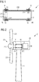
- Fig. 1 shows a bearing arrangement 1 according to the invention, used to support a drive shaft 23 in a drive shaft housing 230.
- the bearing arrangement 1 has a front-end bearing 1F in an annular space 231 at the front end FE of the drive shaft 23, and a back-end bearing 1B in an annular space 232 at the back end BE of the drive shaft 23.
- the diagram indicates an uneven distribution of bearing pads 10 at either end FE, BE.
- FIG. 2 shows the bearing arrangement 1 of Fig. 1 installed to support a drive shaft 23 of a wind turbine generator 3.
- a wind turbine 2 comprises a nacelle 20 on top of a tower 21.
- a rotor 22 comprising a hub 220 and blades 221 mounted to the hub 22 will turn in response to an airflow over the blades 221.
- the rotor 22 is mounted to a drive shaft 23 to transfer the rotation to a generator rotor 30 (indicated in a simplified manner in the diagram) of the generator 3.
- the drive shaft 23 is held in place by a housing 230, and annular bearings 1F, 1B at either end of the drive shaft 23 ensure that the drive shaft 23 is not displaced by the forces acting on it.
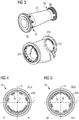
- Fig. 3 shows an exploded view of the drive shaft 23 and the drive shaft housing 230 of Figs. 1 and 2 .
- the drive shaft 23 is shown on the left-hand side, with bearing pads 10 of a front-end annular bearing 1F arranged about the front end FE or drive-end of the drive shaft 23, and bearing pads 10 of a back-end annular bearing 1B arranged about the back end or non-drive-end of the drive shaft 22.
- the bearing pads 10 are shown in the positions in which they are held by the housing 230.
- the housing 230 is shown, indicating the annular spaces or races 231, 232 that contain the bearing pads 10 in their working positions for supporting the drive shaft 23.
- the housing 230 is shaped to partially enclose the drive shaft 23 and to fit about a yaw ring at the top of the wind turbine tower. Openings at either side allow access between the tower 21 and the interior of the nacelle 20 in Fig. 2 .
- An axial load can be borne by thrust bearings at the downwind side, by implementing a fluid bearing on either side of a drive shaft thrust collar.
- Fig. 4 shows a front-end bearing 1F, looking into the housing 230 from the front end FE.
- a horizontal plane H through the drive shaft axis of rotation R is shown, along with a vertical plane V through the axis of rotation R, together dividing the annular form into four equal quadrants.
- the horizontal plane H divides the front-end bearing 1F into an upper half 1F_u and a lower half 1F_l.
- the diagram shows a greater number of fluid bearing pads 10 in the lower half 1F_l (six in this case) and a smaller number of fluid bearing pads 10 in the upper half 1F_u (four in this case).
- the diagram also indicates that the fluid bearing pads 10 are arranged essentially symmetrically about the vertical plane V, disregarding an inherent asymmetry arising from the asymmetrical structure of a fluid bearing pad 10.
- Fig. 5 shows a back-end bearing 1B, looking into the housing 230 from the back end BE.
- a horizontal plane H through the drive shaft axis of rotation R is shown, along with a vertical plane V through the axis of rotation R, dividing the annular form into four quadrants.
- the horizontal plane H divides the back-end bearing 1B into an upper half 1B_u and a lower half 1B_l.
- the diagram shows a greater number of fluid bearing pads 10 in the upper half 1B_u (six in this case) and a smaller number of fluid bearing pads 10 in the lower half 1B_l (four in this case).
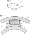
- Fig. 6 shows an exemplary fluid bearing pad 10, with a contact pad 100 mounted on a pivot liner 101.
- the surface of the contact pad 100 is shaped to match the surface of the rotating component (e.g. the drive shaft) which it is to support.
- a fluid can be injected into a space between the contact surface and the outer surface of the supported component. As the supported component rotates, a film of fluid is maintained between these surfaces, allowing smooth rotation.
- Fig. 7 shows a detail of a further embodiment of the bearing arrangement according to the invention, and shows a bearing pad10 in place between the drive shaft 23 and the housing 230.
- the diagram shows the contact pad 100 lying closely about the outer surface of the drive shaft 230.
- a spring-loaded element 11 is arranged to apply pressure to the bearing pad 10 so that the contact pad 100 always lies correctly on the outer surface of the drive shaft 230, even if the rotor applies an axial loading to the drive shaft 23.
Description
- The invention describes a bearing arrangement of an electrical machine, to support a drive shaft inside a housing. Such a bearing arrangement is disclosed for example in
US 4 686 403 . The invention further describes a wind turbine comprising such a bearing arrangement. - A wind turbine generally comprises a nacelle mounted on top of a tower, and enclosing a generator. One type of generator is mounted to a drive shaft, which is turned by a rotor comprising a number of blades mounted to a hub at the upwind end of the nacelle. The rotor turns in response to an airflow over the blades. The drive shaft must be securely held in some way to ensure efficient transfer of the rotation to the generator. To this end, a drive shaft is usually held in place by a housing, with one or more main bearings between drive shaft and housing to allow a smooth motion of the drive shaft. Usually, the main bearing is constructed using a roller bearing such as a ball bearing, roller bearing or tapered roller bearing.
- However, the balls or rollers of such bearings must be machined to a very high degree of precision, and are generally very expensive. Wear and tear can result in damage to one or more bearings and the raceways. To replace a damaged part (roller or ball), it is generally necessary to dismantle the entire cage or race containing the moving parts, so that repair and replacement procedures are generally expensive.
- As an alternative to a ball bearing or roller bearing, it is possible to use a fluid bearing or sliding bearing instead. In a bearing such as a fluid bearing, a thin film of fluid between a bearing pad and the supported component allows the component to slide easily over the bearing pad. However, it is problematic to distribute and design the pads of the fluid or sliding bearings in such a way that wear and maintenance costs are minimized. Generally, multiple pads would be evenly spaced - i.e. arranged in a uniform distribution - around the circumference at each end of the drive shaft, since any bearing design generally aims to distribute the load evenly over the bearing parts. However, in the case of a fluid bearing or a sliding bearing, such a design involves a relatively large number of bearing pads, resulting in higher costs. A large number of pads also leads to increased power loss, a greater "out of tolerance" risk that can lead to an overloaded pad that is slightly too thick, a greater risk of pad failure, etc.
- It is therefore an object of the invention to provide a main bearing that avoids the problems mentioned above.
- This object is achieved by the bearing arrangement of claim 1 and by the wind turbine of claim 13.
- According to the invention, the bearing arrangement is intended for use in an electrical machine that comprises a drive shaft extending through a housing. The bearing arrangement comprises a front-end bearing arranged about a front end of the drive shaft, and a back-end bearing arranged about the other end of the drive shaft, wherein the bearings comprise a plurality of bearing pads arranged in an annular space between the drive shaft and the housing, and wherein at least one bearing comprises an uneven distribution of bearing pads about the drive shaft.
- In the context of the invention, the front-end bearing may be understood to be the front-end main bearing, and the back-end bearing may be understood to be a back-end main bearing. The drive shaft is then held in place by two main bearings, one at either end, i.e. one at the front end or "drive end", and one at the back end or "non-drive-end" of the drive shaft. When the electrical machine is the generator of a wind turbine, the front end is upwind, and the back end is downwind.
- An advantage of the bearing arrangement according to the invention is that the bearing pads are distributed in an optimal manner around the drive shaft to provide support exactly where it is needed. In this way, the drive shaft is always optimally supported under all loading conditions.
- According to the invention, the wind turbine comprises a generator with a drive shaft arranged to transfer rotation from a rotor of the wind turbine to a generator, and further comprises such a bearing arrangement arranged between the drive shaft and a drive shaft housing, installed as a main bearing to support the drive shaft in the housing.
- An advantage of the bearing arrangement according to the invention is that a main bearing that supports the drive shaft can be designed using a relatively economical fluid bearing or sliding bearing, while the wear on the bearing pads can be favourably minimized. In this way, the construction costs and maintenance costs can be reduced.
- Particularly advantageous embodiments and features of the invention are given by the dependent claims, as revealed in the following description. Features of different claim categories may be combined as appropriate to give further embodiments not described herein.
- In the following, it may be assumed that the wind turbine is driven by a rotor comprising a number of blades mounted to a hub at the upwind side. The rotating hub is mounted to a rotating drive shaft that is housed in a bearing housing. An electrical generator is mounted on the drive shaft and bearing housing. The drive shaft must be mounted in such a way that it is free to rotate, and in such a way that it is not affected by opposing forces. To this end, a drive shaft is usually enclosed by a housing, with a main bearing in an annular region at either end of the drive shaft.
- In the context of the invention, a main bearing is to be understood as a set of bearing pads arranged in an annular region at one end of the drive shaft. In the following, without restricting the invention in any way, it may be assumed that a bearing comprises a fluid bearing or a sliding bearing.
- A fluid bearing between a rotating shaft and a housing generally comprises a number of bearing pads each with a contact surface shaped to lie against the shaft. A bearing pad is generally mounted on a pivot or liner. A fluid film between the bearing pad and the rotating shaft ensures that the shaft can rotate smoothly about its axis.
- The drive shaft may be regarded as an essentially cylindrical component arranged to lie horizontally, and which may be virtually divided into an upper half and a lower half by a horizontal plane that contains the axis of rotation of the drive shaft. The inventive bearing distribution can be defined in terms of this horizontal plane, so that the uneven distribution of bearing pads should be understood to mean that different numbers of bearing pads are arranged about the upper half and the lower half. For example, at one end of the drive shaft, a smaller number of bearing pads can be arranged over one semi-circular half, and a larger number of bearing pads can be arranged around the other semi-circular half.
- In one preferred embodiment of the invention, the front-end bearing comprises an uneven distribution of bearing pads about the drive shaft. In a particularly preferred embodiment of the invention, the front-end bearing comprises more bearing pads arranged about the lower half of the drive shaft than the upper half of the drive shaft. For example, for a certain number of bearing pads arranged in the upper semi-circular half of the front-end bearing, there may be one or two more bearing pads arranged in the lower semi-circular half of the front-end bearing. In one exemplary embodiment of the inventive wind turbine generator, the front-end bearing comprises ten fluid bearing pads of which six are arranged about the lower half of the drive shaft.
- Depending on the generator specifications and the loads to which it will be exposed, the uneven bearing distribution in the front-end bearing may be sufficient to ensure a favourable distribution of loads. Therefore, in such a design that involves a front-end bearing with an uneven bearing pad distribution, the back-end bearing can comprise an even bearing pad distribution.
- However, particularly in the case of a large wind turbine generator, the back-end bearing may be subject to significant loading even if the front-end main bearing has been designed to withstand maximum loading. Therefore, in a further preferred embodiment of the invention, the back-end bearing comprises an uneven distribution of bearing pads about the drive shaft. In a particularly preferred embodiment of the invention, the back-end bearing comprises more bearing pads arranged about the upper half of the drive shaft than the lower half of the drive shaft. For example, for a certain number of bearing pads arranged in the lower semi-circular half of the back-end bearing, there may be one or two more bearing pads arranged in the upper semi-circular half of the back-end bearing. In another exemplary embodiment of the inventive wind turbine generator, the back-end bearing comprises ten fluid bearing pads of which six are arranged about the upper half of the drive shaft. In this case also, depending on the generator specifications and the loads to which it will be exposed, the uneven bearing pad distribution in the back-end bearing may be sufficient to ensure a favourable distribution of loads, and the front-end bearing can comprise an even bearing pad distribution.
- Loading on the drive shaft of such a wind turbine generally manifests as a downward force on the front-end of the drive shaft and an upward force on the back-end of the drive shaft. Therefore, in a particularly preferred embodiment of the invention, the front-end main bearing comprises a greater number of bearing pads in its lower half, and the back-end main bearing comprises a greater number of bearing pads in its upper half. In this way, the uneven loading on the drive shaft can be optimally counteracted by the main bearings at either end. Of course, alternative embodiment are equally possible, with an even distribution of pads on the downwind side and an uneven distribution of pads on the upwind side; or an even distribution of pads on the upwind side and an uneven distribution of pads on the downwind side.
- As indicated above, a main bearing comprises a set of bearing pads distributed around one end of the drive shaft. Preferably, the bearing pads of a main bearing are arranged symmetrically about a vertical axis. Such a vertical axis can be defined by a vertical plane containing the axis of rotation of the drive shaft. The vertical symmetry should be understood to relate to the number of bearing pads on either side of the vertical axis, for example five bearing pads on either side of the vertical axis. Using the exemplary front-end main bearing described above, two bearing pads would be arranged in the upper half on one side of the vertical axis, and three bearing pads would be arranged in the lower half on the other side of the vertical axis.
- In a preferred embodiment of the inventive bearing arrangement, at least one bearing is equipped with a pressure application means that is realized to apply pressure to a bearing pad in order to press the bearing pad's contact surface against the outer surface of the drive shaft. In one preferred embodiment, the pressure application means comprises at least one spring-loaded component arranged between the housing and a bearing pad. For example, a pair of springs arranged one on each side of the bearing liner may effectively press the curved contact surface against the drive shaft, even when the drive shaft is subject to axial forces originating from the rotor. In an alternative realization, a pressure application means can comprise an actuator that is driven by a hydraulic motor or a linear motor. In either case, a pressure application means can be realised to press the pad against the shaft surface by applying pressure, or to or pull the pad towards the housing (away from the drive shaft) by reducing the applied pressure. The amount of pressure to be applied to or released from a pad can be adjusted as required in order to adjust the pad's freedom of movement.
- Other objects and features of the present invention will become apparent from the following detailed descriptions considered in conjunction with the accompanying drawings. It is to be understood, however, that the drawings are designed solely for the purposes of illustration and not as a definition of the limits of the invention.
-
Fig. 1 shows a bearing arrangement according to the invention between a drive shaft and a drive shaft housing; -
Fig. 2 shows a bearing arrangement according to the invention supporting a drive shaft of a wind turbine generator; -
Fig. 3 shows an exploded view of the drive shaft and the drive shaft housing ofFig. 1 ; -
Fig. 4 shows a front-end bearing of an embodiment of the bearing arrangement according to the invention; -
Fig. 5 shows a back-end bearing of an embodiment of the bearing arrangement according to the invention; -
Fig. 6 shows a fluid bearing; -
Fig. 7 shows a detail of a further embodiment of the bearing arrangement according to the invention. - In the diagrams, like numbers refer to like objects throughout. Objects in the diagrams are not necessarily drawn to scale.
-
Fig. 1 shows a bearing arrangement 1 according to the invention, used to support adrive shaft 23 in adrive shaft housing 230. The bearing arrangement 1 has a front-end bearing 1F in anannular space 231 at the front end FE of thedrive shaft 23, and a back-end bearing 1B in anannular space 232 at the back end BE of thedrive shaft 23. The diagram indicates an uneven distribution of bearingpads 10 at either end FE, BE. -
Fig. 2 shows the bearing arrangement 1 ofFig. 1 installed to support adrive shaft 23 of awind turbine generator 3. Awind turbine 2 comprises anacelle 20 on top of atower 21. Arotor 22 comprising ahub 220 andblades 221 mounted to thehub 22 will turn in response to an airflow over theblades 221. Therotor 22 is mounted to adrive shaft 23 to transfer the rotation to a generator rotor 30 (indicated in a simplified manner in the diagram) of thegenerator 3. Thedrive shaft 23 is held in place by ahousing 230, andannular bearings drive shaft 23 ensure that thedrive shaft 23 is not displaced by the forces acting on it. -
Fig. 3 shows an exploded view of thedrive shaft 23 and thedrive shaft housing 230 ofFigs. 1 and 2 . Thedrive shaft 23 is shown on the left-hand side, with bearingpads 10 of a front-endannular bearing 1F arranged about the front end FE or drive-end of thedrive shaft 23, and bearingpads 10 of a back-end annular bearing 1B arranged about the back end or non-drive-end of thedrive shaft 22. The bearingpads 10 are shown in the positions in which they are held by thehousing 230. - On the right-hand side of the diagram, the
housing 230 is shown, indicating the annular spaces orraces bearing pads 10 in their working positions for supporting thedrive shaft 23. In this embodiment, thehousing 230 is shaped to partially enclose thedrive shaft 23 and to fit about a yaw ring at the top of the wind turbine tower. Openings at either side allow access between thetower 21 and the interior of thenacelle 20 inFig. 2 . - An axial load can be borne by thrust bearings at the downwind side, by implementing a fluid bearing on either side of a drive shaft thrust collar.
-
Fig. 4 shows a front-end bearing 1F, looking into thehousing 230 from the front end FE. A horizontal plane H through the drive shaft axis of rotation R is shown, along with a vertical plane V through the axis of rotation R, together dividing the annular form into four equal quadrants. The horizontal plane H divides the front-end bearing 1F into an upper half 1F_u and a lower half 1F_l. The diagram shows a greater number offluid bearing pads 10 in the lower half 1F_l (six in this case) and a smaller number offluid bearing pads 10 in the upper half 1F_u (four in this case). The diagram also indicates that thefluid bearing pads 10 are arranged essentially symmetrically about the vertical plane V, disregarding an inherent asymmetry arising from the asymmetrical structure of afluid bearing pad 10. -
Fig. 5 shows a back-end bearing 1B, looking into thehousing 230 from the back end BE. Here also, a horizontal plane H through the drive shaft axis of rotation R is shown, along with a vertical plane V through the axis of rotation R, dividing the annular form into four quadrants. The horizontal plane H divides the back-end bearing 1B into an upper half 1B_u and a lower half 1B_l. The diagram shows a greater number offluid bearing pads 10 in the upper half 1B_u (six in this case) and a smaller number offluid bearing pads 10 in the lower half 1B_l (four in this case). -
Fig. 6 shows an exemplaryfluid bearing pad 10, with acontact pad 100 mounted on apivot liner 101. The surface of thecontact pad 100 is shaped to match the surface of the rotating component (e.g. the drive shaft) which it is to support. As the skilled person will know, a fluid can be injected into a space between the contact surface and the outer surface of the supported component. As the supported component rotates, a film of fluid is maintained between these surfaces, allowing smooth rotation. -
Fig. 7 shows a detail of a further embodiment of the bearing arrangement according to the invention, and shows a bearing pad10 in place between thedrive shaft 23 and thehousing 230. The diagram shows thecontact pad 100 lying closely about the outer surface of thedrive shaft 230. A spring-loadedelement 11 is arranged to apply pressure to thebearing pad 10 so that thecontact pad 100 always lies correctly on the outer surface of thedrive shaft 230, even if the rotor applies an axial loading to thedrive shaft 23. Although the present invention has been disclosed in the form of preferred embodiments and variations thereon, it will be understood that numerous additional modifications and variations could be made thereto without departing from the scope of the invention defined in the appended claims. - For the sake of clarity, it is to be understood that the use of "a" or "an" throughout this application does not exclude a plurality, and "comprising" does not exclude other steps or elements.
Claims (15)
- A bearing arrangement (1) for a wind turbine generator (3) that comprises a drive shaft (23) extending through a housing (230), which bearing arrangement (1) comprises- a front-end bearing (1F) configured to be arranged about a front end (FE) of the drive shaft (23), and- a back-end bearing (1B) configured to be arranged about the opposite end (BE) of the drive shaft (23);wherein the bearings (1F, 1B) comprise a plurality of bearing pads (10) arranged in an annular space (231, 232) between the drive shaft (23) and the housing (230), and wherein
the bearings (1F, 1B) are virtually divided into an upper half (1F_u, 1B_u) and a lower half (1F_l, 1B_l) by a horizontal plane (H) containing the axis of rotation (R) of the drive shaft (23), and wherein an uneven distribution of bearing pads (10) comprises different numbers of bearing pads (10) in the upper half (1F_u, 1B_u) and the lower half (1F_l, 1B_l), and wherein at least one bearing (1F, 1B) comprises an uneven distribution of bearing pads (10) about the drive shaft (23), with more bearing pads (10) in its upper half (1B_U) than in its lower half (1B_l). - A bearing arrangement according to claim 1, wherein the back-end bearing (1B) comprises more bearing pads (10) in its upper half (1B_U) than in its lower half (1B_l).
- A bearing arrangement according to claim 1, wherein the front-end bearing (1F) comprises an uneven distribution of bearing pads (10) about the drive shaft (23).
- A bearing arrangement according to claim 3, wherein the front-end bearing (1F) comprises more bearing pads (10) in its lower half (1F_l) than in its upper half (1F_u).
- A bearing arrangement according to any of the preceding claims, wherein one bearing (1F, 1B) comprises an uneven distribution of bearing pads (10) about the drive shaft (23), and the other bearing (1F, 1B) comprises an even distribution of bearing pads (10) about the drive shaft (23).
- A bearing arrangement according to claim 5 when not dependent on claim 2, wherein the back-end bearing (1B) comprises an even bearing distribution of bearing pads (10) about the drive shaft (23).
- A bearing arrangement according to any of the preceding claims, wherein a bearing (1F, 1B) is symmetrical about a vertical plane (V) containing the axis of rotation (R) of the drive shaft (23).
- A bearing arrangement according to any of the preceding claims, wherein a bearing (1F, 1B) comprises a fluid bearing.
- A bearing arrangement according to any of the preceding claims, wherein a bearing (1F, 1B) comprises a sliding bearing.
- A bearing arrangement according to any of the preceding claims, wherein at least one bearing (1F, 1B) comprises a pressure application means (11) realized to press a contact surface of a bearing pad (10) onto an outer surface of the drive shaft (23).
- A bearing arrangement according to claim 10, wherein the pressure application means (11) comprises a spring-loaded element (11) arranged between the housing (230) and a bearing pad (10).
- A bearing arrangement according to claim 10 or claim 11, wherein the pressure application means comprises an actuator driven by a motor.
- A wind turbine (2) comprising a generator (3) with a drive shaft (23) arranged to transfer rotation from a rotor (22) of the wind turbine (2) to a generator rotor , and further comprising a bearing arrangement (1) according to any of claims 1 to 12 arranged between the drive shaft (23) and a drive shaft housing (230).
- A wind turbine generator according to claim 13, wherein the front-end bearing (1F) comprises ten fluid bearing pads (10) of which six are arranged in its lower half (1F_l).
- A wind turbine generator according to claim 13 or claim 14, wherein the back-end bearing (1B) comprises ten fluid bearings (10) of which six are arranged in its upper half (1B_u).
Priority Applications (4)
| Application Number | Priority Date | Filing Date | Title |
|---|---|---|---|
| EP16181950.3A EP3276192B1 (en) | 2016-07-29 | 2016-07-29 | Bearing arrangement |
| DK16181950.3T DK3276192T3 (en) | 2016-07-29 | 2016-07-29 | bearing arrangement |
| US15/657,309 US10260484B2 (en) | 2016-07-29 | 2017-07-24 | Bearing arrangement |
| CN201710629891.0A CN107664161B (en) | 2016-07-29 | 2017-07-28 | Bearing structure |
Applications Claiming Priority (1)
| Application Number | Priority Date | Filing Date | Title |
|---|---|---|---|
| EP16181950.3A EP3276192B1 (en) | 2016-07-29 | 2016-07-29 | Bearing arrangement |
Publications (2)
| Publication Number | Publication Date |
|---|---|
| EP3276192A1 EP3276192A1 (en) | 2018-01-31 |
| EP3276192B1 true EP3276192B1 (en) | 2019-11-27 |
Family
ID=56567435
Family Applications (1)
| Application Number | Title | Priority Date | Filing Date |
|---|---|---|---|
| EP16181950.3A Active EP3276192B1 (en) | 2016-07-29 | 2016-07-29 | Bearing arrangement |
Country Status (4)
| Country | Link |
|---|---|
| US (1) | US10260484B2 (en) |
| EP (1) | EP3276192B1 (en) |
| CN (1) | CN107664161B (en) |
| DK (1) | DK3276192T3 (en) |
Families Citing this family (19)
| Publication number | Priority date | Publication date | Assignee | Title |
|---|---|---|---|---|
| DK3460238T3 (en) * | 2017-09-20 | 2020-06-15 | Siemens Gamesa Renewable Energy As | Windmill |
| DE102018120808A1 (en) * | 2018-08-27 | 2020-02-27 | Renk Aktiengesellschaft | Bearing arrangement and adjusting screw for adjusting the bearing play |
| AT522164B1 (en) * | 2019-03-07 | 2020-09-15 | Miba Gleitlager Austria Gmbh | Plain bearing |
| AT522155B1 (en) | 2019-03-07 | 2020-09-15 | Miba Gleitlager Austria Gmbh | Plain bearing |
| US11174895B2 (en) | 2019-04-30 | 2021-11-16 | General Electric Company | Bearing for a wind turbine drivetrain having an elastomer support |
| EP3739205B1 (en) | 2019-05-16 | 2022-11-16 | Siemens Gamesa Renewable Energy A/S | Bearing arrangement for a wind turbine and wind turbine |
| EP3739207A1 (en) * | 2019-05-16 | 2020-11-18 | Siemens Gamesa Renewable Energy A/S | Bearing arrangement for a wind turbine and wind turbine |
| EP3739226B1 (en) | 2019-05-16 | 2022-12-14 | Siemens Gamesa Renewable Energy A/S | Bearing arrangement for a wind turbine and wind turbine |
| ES2929123T3 (en) | 2019-05-16 | 2022-11-24 | Siemens Gamesa Renewable Energy As | Bearing arrangement for a wind turbine and wind turbine |
| EP3739208B1 (en) | 2019-05-16 | 2022-11-16 | Siemens Gamesa Renewable Energy A/S | Bearing arrangement for a wind turbine and wind turbine |
| ES2933816T3 (en) | 2019-05-16 | 2023-02-14 | Siemens Gamesa Renewable Energy As | Arrangement of bearings for a wind turbine and wind turbine |
| DK3739206T3 (en) | 2019-05-16 | 2023-09-04 | Siemens Gamesa Renewable Energy As | LEASE ARRANGEMENT FOR A WINDMILL AND WINDMILL |
| EP3792489A1 (en) | 2019-09-16 | 2021-03-17 | Siemens Gamesa Renewable Energy A/S | Bearing arrangement for a wind turbine and wind turbine |
| CN114930018A (en) * | 2020-01-08 | 2022-08-19 | 维斯塔斯风力系统有限公司 | Main bearing housing of a wind turbine |
| DK3904710T3 (en) | 2020-04-28 | 2023-11-27 | Siemens Gamesa Renewable Energy As | FLUID FILM BEARING AND WINDMILL |
| DK3904677T3 (en) * | 2020-04-28 | 2023-11-20 | Siemens Gamesa Renewable Energy As | FLUID FILM BEARING AND WINDMILL |
| EP3904709A1 (en) | 2020-04-28 | 2021-11-03 | Siemens Gamesa Renewable Energy A/S | Fluid film bearing, especially for a rotor hub in a wind turbine |
| CN112228452A (en) * | 2020-09-25 | 2021-01-15 | 青岛海尔空调器有限总公司 | Axle sleeve and air conditioner |
| DE102021106620A1 (en) | 2021-03-18 | 2022-09-22 | Nordex Energy Se & Co. Kg | Rotor bearing housing and wind turbine |
Citations (3)
| Publication number | Priority date | Publication date | Assignee | Title |
|---|---|---|---|---|
| GB154100A (en) * | 1920-01-29 | 1920-11-25 | Kenneth Gauldie | Improvements in bearings |
| US3972572A (en) * | 1974-04-30 | 1976-08-03 | Bbc Brown Boveri & Company Limited | Method and apparatus for modifying vibrational behavior of a rotary shaft |
| US20120228878A1 (en) * | 2009-11-20 | 2012-09-13 | Norman Perner | Tidal Power Plant and Method for the Construction Thereof |
Family Cites Families (22)
| Publication number | Priority date | Publication date | Assignee | Title |
|---|---|---|---|---|
| DE2010628A1 (en) * | 1970-03-06 | 1971-10-14 | Glyco Metall Werke Daelen & So | Tube mill |
| CH558481A (en) | 1972-04-06 | 1975-01-31 | Bbc Brown Boveri & Cie | Plain bearing for heavy machines - is supported by bearing pad segments on spherical projections |
| US3791703A (en) * | 1970-11-30 | 1974-02-12 | Ifield Lab Pty Ltd | Journal support bearings for rotating shafts |
| JPS5324625Y2 (en) * | 1974-01-24 | 1978-06-23 | ||
| US4032199A (en) | 1974-09-25 | 1977-06-28 | Allis-Chalmers Corporation | Apparatus for equalizing radial load on plurality of pivoted bearing pads |
| US4607964A (en) * | 1985-01-17 | 1986-08-26 | The B. F. Goodrich Company | Water lubricated bearing |
| DE3544392A1 (en) * | 1985-12-14 | 1987-06-19 | Kloeckner Humboldt Deutz Ag | AERODYNAMIC SLIDING BEARING |
| US4686403A (en) * | 1986-11-07 | 1987-08-11 | Westinghouse Electric Corp. | Dynamoelectric machine with rockable bearing supports |
| US5372430A (en) * | 1988-04-15 | 1994-12-13 | The B. F. Goodrich Company | Bearing assembly |
| JP2000509134A (en) * | 1997-02-14 | 2000-07-18 | バルメット コーポレイション | Bearing control system for rolls with hydrostatic bearings |
| FI117486B (en) * | 1997-02-14 | 2006-10-31 | Metso Paper Inc | Roller for a paper machine or paper finishing machine |
| FI104206B (en) * | 1998-06-15 | 1999-11-30 | Valmet Corp | Rapid movement arrangement of a hydrostatic bearing roller |
| DE102007003618A1 (en) * | 2007-01-18 | 2008-07-24 | Voith Patent Gmbh | Power generation plant driven by a wind or water flow |
| US8052327B2 (en) * | 2007-06-04 | 2011-11-08 | Ntn Corporation | Hydrostatic gas bearing, rotator and CT scanner |
| US9297363B2 (en) | 2009-07-10 | 2016-03-29 | Siemens Aktiengesellschaft | Wind turbine main bearing |
| WO2012159108A2 (en) * | 2011-05-19 | 2012-11-22 | Vestas Wind Systems A/S | Wind turbine generator with localized air gap control and a wind turbine having such a generator |
| EP2568168A1 (en) * | 2011-09-08 | 2013-03-13 | Siemens Aktiengesellschaft | Direct-drive wind turbine |
| EP2796740B1 (en) * | 2013-04-26 | 2017-03-22 | Siemens Aktiengesellschaft | Direct driven wind turbine with a sliding bearing arrangement |
| DE102013211710C5 (en) * | 2013-06-20 | 2016-11-10 | Siemens Aktiengesellschaft | Wind turbine with a plain bearing |
| CN103762028A (en) | 2013-11-25 | 2014-04-30 | 于洪洲 | Manufacturing method of high-temperature-resistant cables |
| DK3219984T3 (en) * | 2016-03-14 | 2019-04-08 | Siemens Ag | Sliding bearing assembly for a wind turbine |
| EP3252306B1 (en) * | 2016-05-31 | 2018-12-26 | Siemens Aktiengesellschaft | A wind turbine including a sliding bearing |
-
2016
- 2016-07-29 EP EP16181950.3A patent/EP3276192B1/en active Active
- 2016-07-29 DK DK16181950.3T patent/DK3276192T3/en active
-
2017
- 2017-07-24 US US15/657,309 patent/US10260484B2/en active Active
- 2017-07-28 CN CN201710629891.0A patent/CN107664161B/en active Active
Patent Citations (3)
| Publication number | Priority date | Publication date | Assignee | Title |
|---|---|---|---|---|
| GB154100A (en) * | 1920-01-29 | 1920-11-25 | Kenneth Gauldie | Improvements in bearings |
| US3972572A (en) * | 1974-04-30 | 1976-08-03 | Bbc Brown Boveri & Company Limited | Method and apparatus for modifying vibrational behavior of a rotary shaft |
| US20120228878A1 (en) * | 2009-11-20 | 2012-09-13 | Norman Perner | Tidal Power Plant and Method for the Construction Thereof |
Also Published As
| Publication number | Publication date |
|---|---|
| EP3276192A1 (en) | 2018-01-31 |
| US10260484B2 (en) | 2019-04-16 |
| CN107664161A (en) | 2018-02-06 |
| DK3276192T3 (en) | 2020-02-24 |
| CN107664161B (en) | 2020-04-28 |
| US20180030964A1 (en) | 2018-02-01 |
Similar Documents
| Publication | Publication Date | Title |
|---|---|---|
| EP3276192B1 (en) | Bearing arrangement | |
| EP3460238B1 (en) | Wind turbine | |
| US8585367B2 (en) | Wind turbine, a method for servicing a main bearing unit of a wind turbine and use thereof | |
| US8021101B2 (en) | Wind turbine and method of assembling the same | |
| EP1925820B1 (en) | Wind turbine main bearing | |
| EP2694810B2 (en) | Direct-drive wind turbine | |
| US8876477B2 (en) | Wind turbine and a pitch bearing for a wind turbine | |
| US9689174B2 (en) | Wind turbine with yaw bearing lifting device | |
| US20130071246A1 (en) | Bearing element | |
| US20150267687A1 (en) | Wind turbine rotor shaft arrangement | |
| US8827561B2 (en) | Main bearing for a wind turbine | |
| EP3428448B1 (en) | Compound main bearing arrangement for a wind turbine | |
| JP6419177B2 (en) | Propeller blade support device | |
| JP2014511460A (en) | Axial-radial rolling bearings specifically for bearing rotor blades of wind power devices | |
| KR20150005994A (en) | Bearing arrangement | |
| WO2017144058A1 (en) | Wind turbine comprising a moment bearing | |
| US10197093B2 (en) | Bearing arrangement | |
| CN111448399A (en) | Rolling bearing device | |
| US11261915B2 (en) | Method of finishing a bearing ring | |
| CN112955671B (en) | Rolling bearing device and wind power plant | |
| GB2612486A (en) | Self-aligning roller bearing of asymmetric structure | |
| WO2015057126A1 (en) | Wind turbine rotor bearing arrangement | |
| CN105074204A (en) | A hub and bearing system and a turbine comprising the hub and bearing system | |
| US9200619B2 (en) | Wind turbine yaw or pitch bearing utilizing a threaded bearing surface | |
| CN111566364A (en) | Rolling bearing device |
Legal Events
| Date | Code | Title | Description |
|---|---|---|---|
| PUAI | Public reference made under article 153(3) epc to a published international application that has entered the european phase |
Free format text: ORIGINAL CODE: 0009012 |
|
| STAA | Information on the status of an ep patent application or granted ep patent |
Free format text: STATUS: THE APPLICATION HAS BEEN PUBLISHED |
|
| AK | Designated contracting states |
Kind code of ref document: A1 Designated state(s): AL AT BE BG CH CY CZ DE DK EE ES FI FR GB GR HR HU IE IS IT LI LT LU LV MC MK MT NL NO PL PT RO RS SE SI SK SM TR |
|
| AX | Request for extension of the european patent |
Extension state: BA ME |
|
| STAA | Information on the status of an ep patent application or granted ep patent |
Free format text: STATUS: REQUEST FOR EXAMINATION WAS MADE |
|
| 17P | Request for examination filed |
Effective date: 20180705 |
|
| RBV | Designated contracting states (corrected) |
Designated state(s): AL AT BE BG CH CY CZ DE DK EE ES FI FR GB GR HR HU IE IS IT LI LT LU LV MC MK MT NL NO PL PT RO RS SE SI SK SM TR |
|
| STAA | Information on the status of an ep patent application or granted ep patent |
Free format text: STATUS: EXAMINATION IS IN PROGRESS |
|
| 17Q | First examination report despatched |
Effective date: 20181109 |
|
| RAP1 | Party data changed (applicant data changed or rights of an application transferred) |
Owner name: SIEMENS GAMESA RENEWABLE ENERGY A/S |
|
| GRAP | Despatch of communication of intention to grant a patent |
Free format text: ORIGINAL CODE: EPIDOSNIGR1 |
|
| STAA | Information on the status of an ep patent application or granted ep patent |
Free format text: STATUS: GRANT OF PATENT IS INTENDED |
|
| INTG | Intention to grant announced |
Effective date: 20190701 |
|
| GRAS | Grant fee paid |
Free format text: ORIGINAL CODE: EPIDOSNIGR3 |
|
| GRAA | (expected) grant |
Free format text: ORIGINAL CODE: 0009210 |
|
| STAA | Information on the status of an ep patent application or granted ep patent |
Free format text: STATUS: THE PATENT HAS BEEN GRANTED |
|
| AK | Designated contracting states |
Kind code of ref document: B1 Designated state(s): AL AT BE BG CH CY CZ DE DK EE ES FI FR GB GR HR HU IE IS IT LI LT LU LV MC MK MT NL NO PL PT RO RS SE SI SK SM TR |
|
| REG | Reference to a national code |
Ref country code: GB Ref legal event code: FG4D |
|
| REG | Reference to a national code |
Ref country code: CH Ref legal event code: EP |
|
| REG | Reference to a national code |
Ref country code: AT Ref legal event code: REF Ref document number: 1206982 Country of ref document: AT Kind code of ref document: T Effective date: 20191215 |
|
| REG | Reference to a national code |
Ref country code: DE Ref legal event code: R096 Ref document number: 602016024962 Country of ref document: DE |
|
| REG | Reference to a national code |
Ref country code: IE Ref legal event code: FG4D |
|
| REG | Reference to a national code |
Ref country code: DK Ref legal event code: T3 Effective date: 20200219 |
|
| REG | Reference to a national code |
Ref country code: NL Ref legal event code: MP Effective date: 20191127 |
|
| REG | Reference to a national code |
Ref country code: LT Ref legal event code: MG4D |
|
| PG25 | Lapsed in a contracting state [announced via postgrant information from national office to epo] |
Ref country code: SE Free format text: LAPSE BECAUSE OF FAILURE TO SUBMIT A TRANSLATION OF THE DESCRIPTION OR TO PAY THE FEE WITHIN THE PRESCRIBED TIME-LIMIT Effective date: 20191127 Ref country code: LV Free format text: LAPSE BECAUSE OF FAILURE TO SUBMIT A TRANSLATION OF THE DESCRIPTION OR TO PAY THE FEE WITHIN THE PRESCRIBED TIME-LIMIT Effective date: 20191127 Ref country code: NL Free format text: LAPSE BECAUSE OF FAILURE TO SUBMIT A TRANSLATION OF THE DESCRIPTION OR TO PAY THE FEE WITHIN THE PRESCRIBED TIME-LIMIT Effective date: 20191127 Ref country code: NO Free format text: LAPSE BECAUSE OF FAILURE TO SUBMIT A TRANSLATION OF THE DESCRIPTION OR TO PAY THE FEE WITHIN THE PRESCRIBED TIME-LIMIT Effective date: 20200227 Ref country code: GR Free format text: LAPSE BECAUSE OF FAILURE TO SUBMIT A TRANSLATION OF THE DESCRIPTION OR TO PAY THE FEE WITHIN THE PRESCRIBED TIME-LIMIT Effective date: 20200228 Ref country code: LT Free format text: LAPSE BECAUSE OF FAILURE TO SUBMIT A TRANSLATION OF THE DESCRIPTION OR TO PAY THE FEE WITHIN THE PRESCRIBED TIME-LIMIT Effective date: 20191127 Ref country code: BG Free format text: LAPSE BECAUSE OF FAILURE TO SUBMIT A TRANSLATION OF THE DESCRIPTION OR TO PAY THE FEE WITHIN THE PRESCRIBED TIME-LIMIT Effective date: 20200227 Ref country code: FI Free format text: LAPSE BECAUSE OF FAILURE TO SUBMIT A TRANSLATION OF THE DESCRIPTION OR TO PAY THE FEE WITHIN THE PRESCRIBED TIME-LIMIT Effective date: 20191127 |
|
| PG25 | Lapsed in a contracting state [announced via postgrant information from national office to epo] |
Ref country code: HR Free format text: LAPSE BECAUSE OF FAILURE TO SUBMIT A TRANSLATION OF THE DESCRIPTION OR TO PAY THE FEE WITHIN THE PRESCRIBED TIME-LIMIT Effective date: 20191127 Ref country code: RS Free format text: LAPSE BECAUSE OF FAILURE TO SUBMIT A TRANSLATION OF THE DESCRIPTION OR TO PAY THE FEE WITHIN THE PRESCRIBED TIME-LIMIT Effective date: 20191127 Ref country code: IS Free format text: LAPSE BECAUSE OF FAILURE TO SUBMIT A TRANSLATION OF THE DESCRIPTION OR TO PAY THE FEE WITHIN THE PRESCRIBED TIME-LIMIT Effective date: 20200327 |
|
| PG25 | Lapsed in a contracting state [announced via postgrant information from national office to epo] |
Ref country code: AL Free format text: LAPSE BECAUSE OF FAILURE TO SUBMIT A TRANSLATION OF THE DESCRIPTION OR TO PAY THE FEE WITHIN THE PRESCRIBED TIME-LIMIT Effective date: 20191127 |
|
| PG25 | Lapsed in a contracting state [announced via postgrant information from national office to epo] |
Ref country code: EE Free format text: LAPSE BECAUSE OF FAILURE TO SUBMIT A TRANSLATION OF THE DESCRIPTION OR TO PAY THE FEE WITHIN THE PRESCRIBED TIME-LIMIT Effective date: 20191127 Ref country code: PT Free format text: LAPSE BECAUSE OF FAILURE TO SUBMIT A TRANSLATION OF THE DESCRIPTION OR TO PAY THE FEE WITHIN THE PRESCRIBED TIME-LIMIT Effective date: 20200419 Ref country code: ES Free format text: LAPSE BECAUSE OF FAILURE TO SUBMIT A TRANSLATION OF THE DESCRIPTION OR TO PAY THE FEE WITHIN THE PRESCRIBED TIME-LIMIT Effective date: 20191127 Ref country code: CZ Free format text: LAPSE BECAUSE OF FAILURE TO SUBMIT A TRANSLATION OF THE DESCRIPTION OR TO PAY THE FEE WITHIN THE PRESCRIBED TIME-LIMIT Effective date: 20191127 Ref country code: RO Free format text: LAPSE BECAUSE OF FAILURE TO SUBMIT A TRANSLATION OF THE DESCRIPTION OR TO PAY THE FEE WITHIN THE PRESCRIBED TIME-LIMIT Effective date: 20191127 |
|
| REG | Reference to a national code |
Ref country code: DE Ref legal event code: R097 Ref document number: 602016024962 Country of ref document: DE |
|
| PG25 | Lapsed in a contracting state [announced via postgrant information from national office to epo] |
Ref country code: SK Free format text: LAPSE BECAUSE OF FAILURE TO SUBMIT A TRANSLATION OF THE DESCRIPTION OR TO PAY THE FEE WITHIN THE PRESCRIBED TIME-LIMIT Effective date: 20191127 Ref country code: SM Free format text: LAPSE BECAUSE OF FAILURE TO SUBMIT A TRANSLATION OF THE DESCRIPTION OR TO PAY THE FEE WITHIN THE PRESCRIBED TIME-LIMIT Effective date: 20191127 |
|
| REG | Reference to a national code |
Ref country code: AT Ref legal event code: MK05 Ref document number: 1206982 Country of ref document: AT Kind code of ref document: T Effective date: 20191127 |
|
| PLBE | No opposition filed within time limit |
Free format text: ORIGINAL CODE: 0009261 |
|
| STAA | Information on the status of an ep patent application or granted ep patent |
Free format text: STATUS: NO OPPOSITION FILED WITHIN TIME LIMIT |
|
| 26N | No opposition filed |
Effective date: 20200828 |
|
| PG25 | Lapsed in a contracting state [announced via postgrant information from national office to epo] |
Ref country code: SI Free format text: LAPSE BECAUSE OF FAILURE TO SUBMIT A TRANSLATION OF THE DESCRIPTION OR TO PAY THE FEE WITHIN THE PRESCRIBED TIME-LIMIT Effective date: 20191127 Ref country code: PL Free format text: LAPSE BECAUSE OF FAILURE TO SUBMIT A TRANSLATION OF THE DESCRIPTION OR TO PAY THE FEE WITHIN THE PRESCRIBED TIME-LIMIT Effective date: 20191127 Ref country code: AT Free format text: LAPSE BECAUSE OF FAILURE TO SUBMIT A TRANSLATION OF THE DESCRIPTION OR TO PAY THE FEE WITHIN THE PRESCRIBED TIME-LIMIT Effective date: 20191127 |
|
| PG25 | Lapsed in a contracting state [announced via postgrant information from national office to epo] |
Ref country code: IT Free format text: LAPSE BECAUSE OF FAILURE TO SUBMIT A TRANSLATION OF THE DESCRIPTION OR TO PAY THE FEE WITHIN THE PRESCRIBED TIME-LIMIT Effective date: 20191127 |
|
| PG25 | Lapsed in a contracting state [announced via postgrant information from national office to epo] |
Ref country code: MC Free format text: LAPSE BECAUSE OF FAILURE TO SUBMIT A TRANSLATION OF THE DESCRIPTION OR TO PAY THE FEE WITHIN THE PRESCRIBED TIME-LIMIT Effective date: 20191127 |
|
| REG | Reference to a national code |
Ref country code: CH Ref legal event code: PL |
|
| REG | Reference to a national code |
Ref country code: BE Ref legal event code: MM Effective date: 20200731 |
|
| PG25 | Lapsed in a contracting state [announced via postgrant information from national office to epo] |
Ref country code: LU Free format text: LAPSE BECAUSE OF NON-PAYMENT OF DUE FEES Effective date: 20200729 Ref country code: LI Free format text: LAPSE BECAUSE OF NON-PAYMENT OF DUE FEES Effective date: 20200731 Ref country code: CH Free format text: LAPSE BECAUSE OF NON-PAYMENT OF DUE FEES Effective date: 20200731 Ref country code: FR Free format text: LAPSE BECAUSE OF NON-PAYMENT OF DUE FEES Effective date: 20200731 |
|
| PG25 | Lapsed in a contracting state [announced via postgrant information from national office to epo] |
Ref country code: BE Free format text: LAPSE BECAUSE OF NON-PAYMENT OF DUE FEES Effective date: 20200731 |
|
| PG25 | Lapsed in a contracting state [announced via postgrant information from national office to epo] |
Ref country code: IE Free format text: LAPSE BECAUSE OF NON-PAYMENT OF DUE FEES Effective date: 20200729 |
|
| PG25 | Lapsed in a contracting state [announced via postgrant information from national office to epo] |
Ref country code: TR Free format text: LAPSE BECAUSE OF FAILURE TO SUBMIT A TRANSLATION OF THE DESCRIPTION OR TO PAY THE FEE WITHIN THE PRESCRIBED TIME-LIMIT Effective date: 20191127 Ref country code: MT Free format text: LAPSE BECAUSE OF FAILURE TO SUBMIT A TRANSLATION OF THE DESCRIPTION OR TO PAY THE FEE WITHIN THE PRESCRIBED TIME-LIMIT Effective date: 20191127 Ref country code: CY Free format text: LAPSE BECAUSE OF FAILURE TO SUBMIT A TRANSLATION OF THE DESCRIPTION OR TO PAY THE FEE WITHIN THE PRESCRIBED TIME-LIMIT Effective date: 20191127 |
|
| PG25 | Lapsed in a contracting state [announced via postgrant information from national office to epo] |
Ref country code: MK Free format text: LAPSE BECAUSE OF FAILURE TO SUBMIT A TRANSLATION OF THE DESCRIPTION OR TO PAY THE FEE WITHIN THE PRESCRIBED TIME-LIMIT Effective date: 20191127 |
|
| REG | Reference to a national code |
Ref country code: DE Ref legal event code: R082 Ref document number: 602016024962 Country of ref document: DE Representative=s name: SAUTHOFF, KARSTEN, DIPL.-ING. UNIV., DE |
|
| PGFP | Annual fee paid to national office [announced via postgrant information from national office to epo] |
Ref country code: GB Payment date: 20230724 Year of fee payment: 8 |
|
| PGFP | Annual fee paid to national office [announced via postgrant information from national office to epo] |
Ref country code: DK Payment date: 20230724 Year of fee payment: 8 Ref country code: DE Payment date: 20230720 Year of fee payment: 8 |