JP6958582B2 - Ejector type refrigeration cycle device - Google Patents
Ejector type refrigeration cycle device Download PDFInfo
- Publication number
- JP6958582B2 JP6958582B2 JP2019035228A JP2019035228A JP6958582B2 JP 6958582 B2 JP6958582 B2 JP 6958582B2 JP 2019035228 A JP2019035228 A JP 2019035228A JP 2019035228 A JP2019035228 A JP 2019035228A JP 6958582 B2 JP6958582 B2 JP 6958582B2
- Authority
- JP
- Japan
- Prior art keywords
- refrigerant
- valve
- flow path
- unit
- flow rate
- Prior art date
- Legal status (The legal status is an assumption and is not a legal conclusion. Google has not performed a legal analysis and makes no representation as to the accuracy of the status listed.)
- Active
Links
Images


Classifications
-
- F—MECHANICAL ENGINEERING; LIGHTING; HEATING; WEAPONS; BLASTING
- F25—REFRIGERATION OR COOLING; COMBINED HEATING AND REFRIGERATION SYSTEMS; HEAT PUMP SYSTEMS; MANUFACTURE OR STORAGE OF ICE; LIQUEFACTION SOLIDIFICATION OF GASES
- F25B—REFRIGERATION MACHINES, PLANTS OR SYSTEMS; COMBINED HEATING AND REFRIGERATION SYSTEMS; HEAT PUMP SYSTEMS
- F25B41/00—Fluid-circulation arrangements
- F25B41/30—Expansion means; Dispositions thereof
- F25B41/39—Dispositions with two or more expansion means arranged in series, i.e. multi-stage expansion, on a refrigerant line leading to the same evaporator
-
- F—MECHANICAL ENGINEERING; LIGHTING; HEATING; WEAPONS; BLASTING
- F04—POSITIVE - DISPLACEMENT MACHINES FOR LIQUIDS; PUMPS FOR LIQUIDS OR ELASTIC FLUIDS
- F04F—PUMPING OF FLUID BY DIRECT CONTACT OF ANOTHER FLUID OR BY USING INERTIA OF FLUID TO BE PUMPED; SIPHONS
- F04F5/00—Jet pumps, i.e. devices in which flow is induced by pressure drop caused by velocity of another fluid flow
- F04F5/02—Jet pumps, i.e. devices in which flow is induced by pressure drop caused by velocity of another fluid flow the inducing fluid being liquid
- F04F5/04—Jet pumps, i.e. devices in which flow is induced by pressure drop caused by velocity of another fluid flow the inducing fluid being liquid displacing elastic fluids
-
- F—MECHANICAL ENGINEERING; LIGHTING; HEATING; WEAPONS; BLASTING
- F04—POSITIVE - DISPLACEMENT MACHINES FOR LIQUIDS; PUMPS FOR LIQUIDS OR ELASTIC FLUIDS
- F04F—PUMPING OF FLUID BY DIRECT CONTACT OF ANOTHER FLUID OR BY USING INERTIA OF FLUID TO BE PUMPED; SIPHONS
- F04F5/00—Jet pumps, i.e. devices in which flow is induced by pressure drop caused by velocity of another fluid flow
- F04F5/44—Component parts, details, or accessories not provided for in, or of interest apart from, groups F04F5/02 - F04F5/42
- F04F5/48—Control
-
- F—MECHANICAL ENGINEERING; LIGHTING; HEATING; WEAPONS; BLASTING
- F25—REFRIGERATION OR COOLING; COMBINED HEATING AND REFRIGERATION SYSTEMS; HEAT PUMP SYSTEMS; MANUFACTURE OR STORAGE OF ICE; LIQUEFACTION SOLIDIFICATION OF GASES
- F25B—REFRIGERATION MACHINES, PLANTS OR SYSTEMS; COMBINED HEATING AND REFRIGERATION SYSTEMS; HEAT PUMP SYSTEMS
- F25B1/00—Compression machines, plants or systems with non-reversible cycle
-
- F—MECHANICAL ENGINEERING; LIGHTING; HEATING; WEAPONS; BLASTING
- F25—REFRIGERATION OR COOLING; COMBINED HEATING AND REFRIGERATION SYSTEMS; HEAT PUMP SYSTEMS; MANUFACTURE OR STORAGE OF ICE; LIQUEFACTION SOLIDIFICATION OF GASES
- F25B—REFRIGERATION MACHINES, PLANTS OR SYSTEMS; COMBINED HEATING AND REFRIGERATION SYSTEMS; HEAT PUMP SYSTEMS
- F25B49/00—Arrangement or mounting of control or safety devices
- F25B49/02—Arrangement or mounting of control or safety devices for compression type machines, plants or systems
Description
本発明は、エジェクタ式冷凍サイクル装置に関するものである。 The present invention relates to an ejector type refrigeration cycle device.
従来のエジェクタ式冷凍サイクル装置として、エジェクタの吸引部に流入する冷媒の流量を調整する流量調整部を備えるものがある。この流量調整部の弁機構としては、電磁弁や機械的な弁が用いられていた(例えば、特許文献1参照)。電磁弁では、電磁アクチュエータによって弁体が駆動される。機械的な弁では、例えば、感温室の圧力と流れる冷媒の圧力との圧力差およびばねによって弁体が駆動される。 Some conventional ejector-type refrigeration cycle devices include a flow rate adjusting unit that adjusts the flow rate of the refrigerant flowing into the suction unit of the ejector. A solenoid valve or a mechanical valve has been used as the valve mechanism of the flow rate adjusting unit (see, for example, Patent Document 1). In a solenoid valve, the valve body is driven by an electromagnetic actuator. In a mechanical valve, for example, the valve body is driven by a pressure difference between the pressure of the greenhouse and the pressure of the flowing refrigerant and a spring.
上記の通り、従来の流量調整部では、電磁弁、機械的な弁等が用いられている。このため、流量調整部の体格が大きい。 As described above, a solenoid valve, a mechanical valve, or the like is used in the conventional flow rate adjusting unit. Therefore, the physique of the flow rate adjusting unit is large.
本発明は上記点に鑑みて、流量調整部の弁機構として、従来の電磁弁や機械式の弁を用いる場合と比較して、流量調整部の体格を小さくすることができるエジェクタ式冷凍サイクル装置を提供することを目的とする。 In view of the above points, the present invention is an ejector type refrigeration cycle apparatus capable of reducing the body size of the flow rate adjusting unit as compared with the case where a conventional solenoid valve or a mechanical valve is used as the valve mechanism of the flow rate adjusting unit. The purpose is to provide.
上記目的を達成するため、請求項1または2に記載の発明によれば、
エジェクタ式冷凍サイクル装置は、
冷媒を圧縮して吐出する圧縮機(12)と、
圧縮機から吐出された冷媒を放熱させる放熱器(14)と、
放熱器から流出した冷媒を噴出させるノズル部(16a)、ノズル部から噴出された冷媒の流れにより冷媒を吸引する吸引部(16b)、およびノズル部から噴出された冷媒と吸引部から吸引された冷媒とを混合して昇圧する昇圧部(16c)を含むエジェクタ(16)と、
吸引部に流入する冷媒の流量を調整する弁部品(X1)を含む流量調整部とを備え、
弁部品は、
冷媒が流通する冷媒室(X19)、冷媒室に連通する第1冷媒孔(X16)、および冷媒室に連通する第2冷媒孔(X17)が形成される基部(X11、X121、X13)と、
自らの温度が変化すると変位する駆動部(X123、X124、X125)と、
駆動部の温度の変化による変位を増幅する増幅部(X126、X127)と、
増幅部によって増幅された変位が伝達されて冷媒室内で動くことで、冷媒室を介した第1冷媒孔と第2冷媒孔との間の連通、遮断を切り替える可動部(X128)と、を有し、
駆動部が温度の変化によって変位したときに、駆動部が付勢位置(XP2)において増幅部を付勢することで、増幅部がヒンジ(XP0)を支点として変位するとともに、増幅部と可動部の接続位置(XP3)で増幅部が可動部を付勢し、
ヒンジから付勢位置までの距離よりも、ヒンジから接続位置までの距離の方が長い。
さらに、請求項1に記載の発明によれば、
エジェクタ式冷凍サイクル装置は、
放熱器から流出した冷媒を一方の冷媒と他方の冷媒とに分岐させる分岐部(20)と、
冷媒を蒸発させる第1蒸発器(18)と、
冷媒を蒸発させる第2蒸発器(24)とを備え、
一方の冷媒がノズル部、昇圧部、第1蒸発器の順に流れるように、分岐部、エジェクタおよび第1蒸発器は接続されており、
他方の冷媒が流量調整部、第2蒸発器、吸引部の順に流れるように、分岐部、流量調整部、第2蒸発器およびエジェクタは接続されており、
流量調整部(50)は、第2蒸発器に流入する冷媒の流量を調整するとともに、第2蒸発器に流入する冷媒を減圧させ、
流量調整部(50)は、流量調整部の冷媒入口部(51a)から流量調整部の冷媒出口部(51b)に至る冷媒流路を形成する流路形成部品(51、X2)と、
冷媒流路を開閉する開閉弁(50a)とを有し、
冷媒流路は、固定絞り(50b)と、冷媒入口部から流入した冷媒を固定絞りを迂回させて冷媒出口部に導くための迂回流路(XV1、XV2、55a、55b)とを含み、
弁部品は、迂回流路を開閉するとともに、迂回流路が開状態のときに迂回流路を流れる冷媒を減圧させる。
また、請求項2に記載の発明によれば、
エジェクタ式冷凍サイクル装置は、
昇圧部から流出した冷媒を気相冷媒と液相冷媒とに分離し、分離した気相冷媒を圧縮機に流入させる気液分離器(60)と、
気液分離器で分離された液相冷媒を蒸発させ、蒸発後の冷媒を吸引部に流入させる蒸発器(62)と、
放熱器から流出した冷媒を、エジェクタおよび気液分離器を迂回させて、蒸発器に導くバイパス流路(64)とを備え、
流量調整部(68)は、バイパス流路を流れる冷媒の流量を調整するとともに、バイパス流路を流れる冷媒を減圧させる。
According to the invention according to
The ejector type refrigeration cycle device is
A compressor (12) that compresses and discharges the refrigerant,
A radiator (14) that dissipates the refrigerant discharged from the compressor, and
The nozzle portion (16a) for ejecting the refrigerant flowing out of the radiator, the suction portion (16b) for sucking the refrigerant by the flow of the refrigerant ejected from the nozzle portion, and the refrigerant ejected from the nozzle portion and the suction portion sucked. An ejector (16) including a booster (16c) that mixes and boosts the refrigerant, and
And a flow rate adjustment unit which includes a valve part for adjusting the flow rate of refrigerant flowing into the suction unit (X1),
Valve parts
Bases (X11, X121, X13) in which a refrigerant chamber (X19) through which a refrigerant flows, a first refrigerant hole (X16) communicating with the refrigerant chamber, and a second refrigerant hole (X17) communicating with the refrigerant chamber are formed.
Drive units (X123, X124, X125) that displace when their temperature changes,
Amplifying units (X126, X127) that amplify the displacement due to changes in the temperature of the driving unit,
By transmitting the displacement amplified by the amplification unit and moving in the refrigerant chamber, there is a movable portion (X128) that switches between communication and shutoff between the first refrigerant hole and the second refrigerant hole via the refrigerant chamber. death,
When the drive unit is displaced due to a change in temperature, the drive unit biases the amplification unit at the urging position (XP2), so that the amplification unit is displaced with the hinge (XP0) as a fulcrum, and the amplification unit and the movable unit are displaced. The amplification part urges the movable part at the connection position (XP3) of
The distance from the hinge to the connection position is longer than the distance from the hinge to the urging position.
Further, according to the invention of
The ejector type refrigeration cycle device is
A branch portion (20) that branches the refrigerant flowing out of the radiator into one refrigerant and the other refrigerant.
The first evaporator (18) that evaporates the refrigerant and
It is equipped with a second evaporator (24) that evaporates the refrigerant.
The branch portion, the ejector, and the first evaporator are connected so that one of the refrigerants flows in the order of the nozzle portion, the boosting portion, and the first evaporator.
The branch part, the flow rate adjusting part, the second evaporator and the ejector are connected so that the other refrigerant flows in the order of the flow rate adjusting part, the second evaporator, and the suction part.
The flow rate adjusting unit (50) adjusts the flow rate of the refrigerant flowing into the second evaporator and reduces the pressure of the refrigerant flowing into the second evaporator.
The flow rate adjusting unit (50) includes a flow path forming component (51, X2) that forms a refrigerant flow path from the refrigerant inlet portion (51a) of the flow rate adjusting unit to the refrigerant outlet portion (51b) of the flow rate adjusting unit.
It has an on-off valve (50a) that opens and closes the refrigerant flow path.
The refrigerant flow path includes a fixed throttle (50b) and a bypass flow path (XV1, XV2, 55a, 55b) for guiding the refrigerant flowing in from the refrigerant inlet portion by bypassing the fixed throttle portion to the refrigerant outlet portion.
The valve component opens and closes the bypass flow path and reduces the pressure of the refrigerant flowing through the bypass flow path when the bypass flow path is open.
Further, according to the invention of claim 2,
The ejector type refrigeration cycle device is
A gas-liquid separator (60) that separates the refrigerant flowing out from the booster into a gas-phase refrigerant and a liquid-phase refrigerant, and allows the separated vapor-phase refrigerant to flow into the compressor.
An evaporator (62) that evaporates the liquid-phase refrigerant separated by the gas-liquid separator and allows the evaporated refrigerant to flow into the suction unit.
It is provided with a bypass flow path (64) that bypasses the ejector and the gas-liquid separator and guides the refrigerant flowing out of the radiator to the evaporator.
The flow rate adjusting unit (68) adjusts the flow rate of the refrigerant flowing through the bypass flow path and reduces the pressure of the refrigerant flowing through the bypass flow path.
請求項1、2に記載の発明によれば、流量調整部の弁機構として、弁部品を用いている。弁部品は、従来の電磁弁や機械式の弁と比べた小型化が可能である。弁部品の増幅部は、梃子として機能するので、駆動部の温度変化に応じた変位量が、梃子によって増幅されて可動部に伝わる。駆動部の変位量が梃子を利用して増幅されることが、そのような梃子を利用しない従来の電磁弁や機械式の弁と比べた小型化に寄与する。よって、流量調整部の弁機構として、従来の電磁弁や機械式の弁を用いる場合と比較して、流量調整部の体格を小さくすることができる。
According to the inventions of
なお、各構成要素等に付された括弧付きの参照符号は、その構成要素等と後述する実施形態に記載の具体的な構成要素等との対応関係の一例を示すものである。 The reference reference numerals in parentheses attached to each component or the like indicate an example of the correspondence between the component or the like and the specific component or the like described in the embodiment described later.
以下、本発明の実施形態について図に基づいて説明する。なお、以下の各実施形態相互において、互いに同一もしくは均等である部分には、同一符号を付して説明を行う。 Hereinafter, embodiments of the present invention will be described with reference to the drawings. In each of the following embodiments, parts that are the same or equal to each other will be described with the same reference numerals.
(第1実施形態)
図1に示す本実施形態の冷凍サイクル装置10は、車両に搭載されるエジェクタ式冷凍サイクル装置である。冷凍サイクル装置10は、図示しない車室の冷房と、図示しないクールボックスの冷蔵とを行う。クールボックスは、飲み物等を冷却する車両用冷蔵庫である。クールボックスは、ケースを備えている。ケースは、冷却対象物が収容される庫内の空間を形成するとともに、冷凍サイクル装置10の構成部品を収容する。
(First Embodiment)
The
冷凍サイクル装置10は、圧縮機12と、放熱器14と、膨張弁15と、エジェクタ16と、第1蒸発器18と、分岐部20と、弁装置22と、第2蒸発器24とを備える。これらの冷凍サイクル装置10の構成部品は、蒸気圧縮式の冷凍サイクルを構成するように、互いに接続されている。
The
圧縮機12は、吸入した冷媒を圧縮して吐出する。圧縮機12は、車両のエンジンによって駆動される。放熱器14は、圧縮機12で圧縮された冷媒と車室の外部の空気との熱交換により、冷媒を放熱させる。膨張弁15は、分岐部20とエジェクタ16の冷媒流れの上流側との間に設けられている。膨張弁15は、放熱器14から流出した冷媒を減圧膨張させる。膨張弁15は、温度式膨張弁であり、第1蒸発器18から流出した冷媒の過熱度に応じて、膨張弁15を通過する冷媒の流量を調整する。
The
エジェクタ16は、膨張弁15から流出した冷媒を減圧させ、第1蒸発器18に向けて流出させる。エジェクタ16は、ノズル部16aと、吸引部16bと、昇圧部16cとを有する。ノズル部16aは、流入した冷媒を噴射し、冷媒を減圧膨張させる。吸引部16bは、ノズル部16aから噴出された冷媒の流れにより冷媒を吸引する。昇圧部16cは、ノズル部16aから噴出された冷媒と、吸引部16bから吸引された冷媒とを混合して昇圧する。昇圧部16cは、昇圧した冷媒を第1蒸発器18に向けて流出させる。
The
第1蒸発器18は、エジェクタ16から流出した冷媒と車室の内部へ送られる空気との熱交換により、空気を冷却するとともに、冷媒を蒸発させる。分岐部20は、放熱器14の冷媒流れ下流側とエジェクタ16の冷媒流れ上流側との間に設けられている。分岐部20は、放熱器14の冷媒流れ下流側の冷媒を一方と他方とに分岐させる。分岐した一方の冷媒は、エジェクタ16のノズル部16aに向かって流れる。分岐した他方の冷媒は、エジェクタの吸引部16bに向かって流れる。
The
弁装置22は、分岐部20からエジェクタ16の吸引部16bに向かって冷媒が流れる吸引側流路21に設けられている。弁装置22は、第2蒸発器24に流入する冷媒の流量を調整するとともに、第2蒸発器24に流入する冷媒を減圧させる流量調整部である。弁装置22は、直列に接続されたマイクロバルブX1と固定絞り23とを含む。弁装置22は、マイクロバルブX1と固定絞り23とが一体化されたものである。なお、冷媒の流量を調整することには、流量をゼロにすることが含まれる。吸引側流路21を流れる冷媒の流量を調整することと、第2蒸発器24に流入する冷媒の流量を調整することと、吸引部16bに流入する冷媒の流量を調整することとは、同じ意味である。
The
マイクロバルブX1は、吸引側流路21を開閉する。マイクロバルブX1は、吸引側流路21に冷媒が流れる状態と冷媒が流れない状態とを切り替える切替弁として用いられている。固定絞り23は、絞り開度が固定されている。すなわち、固定絞り23は、流路断面積が固定されている。固定絞り23は、吸引側流路21に冷媒が流れる状態のときに、冷媒を減圧膨張させる。弁装置22は、クールボックスのケースの内部に収容されている。弁装置22の構成については後述する。
The micro valve X1 opens and closes the suction
第2蒸発器24は、吸引側流路21のうち弁装置22と吸引部16bとの間に設けられている。第2蒸発器24は、クールボックスのケースの内部に収容されている。第2蒸発器24は、冷媒とクールボックスの庫内の空気との熱交換により、庫内の空気を冷却し、冷媒を蒸発させる。
The
次に、冷凍サイクル装置10の作動について説明する。
Next, the operation of the
クールボックスの使用時では、マイクロバルブX1は開弁している。圧縮機12の作動によって高温高圧の冷媒が圧縮機12から吐出される。圧縮機12から吐出された高温高圧の冷媒は、放熱器14で放熱される。放熱器14で放熱された冷媒は、分岐部20で一方の冷媒と他方の冷媒とに分岐される。
When using the cool box, the micro valve X1 is open. By operating the
分岐された一方の冷媒は、膨張弁15で減圧膨張された後、エジェクタ16のノズル部16aに流入する。ノズル部16aに流入した冷媒は、ノズル部16aから噴射されることで、減圧膨張される。ノズル部16aから噴射された冷媒は、吸引部16bから流入した冷媒とともに、昇圧部16cに流入する。昇圧部16cに流入した冷媒は、昇圧された後、昇圧部16cから流出する。昇圧部16cから流出した冷媒は、第1蒸発器18を流れる。第1蒸発器18で、冷媒が蒸発することで、車室の内部の空気が冷却される。これにより、車室の内部の冷房が行われる。第1蒸発器18から流出した冷媒は、圧縮機12に吸入される。
One of the branched refrigerants is decompressed and expanded by the
分岐された他方の冷媒は、弁装置22に流入する。弁装置22に流入した冷媒は、固定絞り23で減圧され、弁装置22から流出する。弁装置22から流出した冷媒は、第2蒸発器24に流入する。第2蒸発器24で、冷媒が蒸発することで、クールボックスの庫内の空気が冷却される。これにより、クールボックスの冷蔵が行われる。第2蒸発器24から流出した冷媒は、吸引部16bに流入する。
The other branched refrigerant flows into the
このように、分岐部20で分岐された一方の冷媒が、ノズル部16a、昇圧部16c、第1蒸発器18の順に流れるように、分岐部20、エジェクタ16および第1蒸発器18は接続されている。分岐部20で分岐された他方の冷媒が、弁装置22、第2蒸発器24、吸引部16bの順に流れるように、分岐部20、弁装置22、第2蒸発器24およびエジェクタ16は接続されている。
In this way, the
クールボックスの非使用時では、マイクロバルブX1が閉状態とされる。このため、分岐部20から吸引部16bの間には、冷媒が流れない。他の冷媒流れは、クールボックスの使用時と同じである。
When the cool box is not used, the micro valve X1 is closed. Therefore, the refrigerant does not flow between the
次に、弁装置22の構成について説明する。図2に示すように、弁装置22は、流路形成部材30と、バルブモジュールX0とを有する。
Next, the configuration of the
流路形成部材30は、内部に冷媒流路31を形成している。冷媒流路31は、第1流路32と、第2流路33と、第3流路34と、固定絞り23とを含む。第1流路32は、流路形成部材30の冷媒入口部30aに連通している。第3流路34は、流路形成部材30の冷媒出口部30bに連通している。第1流路32と第2流路33とは、直接、連通しておらず、バルブモジュールX0の流路を介して、連通している。第2流路33と第3流路34とは、固定絞り23を介して、連通している。固定絞り23は、第2流路33と第3流路34とのそれぞれよりも流路断面積が小さな流路である。流路断面積は、流路の横断面の面積である。流路形成部材30は、金属製の部材である。
The flow
[バルブモジュールX0の構成]
バルブモジュールX0は、流路形成部材30に接続されている。バルブモジュールX0は、マイクロバルブX1、バルブケーシングX2、封止部材X3、2つのOリングX4、X5、2本の電気配線X6、X7を有している。
[Configuration of valve module X0]
The valve module X0 is connected to the flow
マイクロバルブX1は、板形状の弁部品であり、主として半導体チップによって構成されている。マイクロバルブX1は、半導体チップ以外の部品を有していてもいなくてもよい。したがって、マイクロバルブX1を小型に構成することができる。マイクロバルブX1の厚さ方向の長さは例えば2mmであり、厚さ方向に直交する長手方向の長さは例えば10mmであり、長手方向にも厚さ方向にも直交する短手方向の長さは例えば5mmであるが、これに限定されない。 The micro valve X1 is a plate-shaped valve component, and is mainly composed of a semiconductor chip. The microvalve X1 may or may not have parts other than the semiconductor chip. Therefore, the micro valve X1 can be made compact. The length of the microvalve X1 in the thickness direction is, for example, 2 mm, the length in the longitudinal direction orthogonal to the thickness direction is, for example, 10 mm, and the length in the lateral direction orthogonal to both the longitudinal direction and the thickness direction. Is, for example, 5 mm, but is not limited thereto.
上述の通り、マイクロバルブX1は、開閉弁として機能する。マイクロバルブX1への通電、非通電が切り替わることで、開閉が切り替わる。具体的には、図3に示すように、マイクロバルブX1は、通電時に開弁し、非通電時に閉弁する常閉弁である。 As described above, the micro valve X1 functions as an on-off valve. Opening and closing is switched by switching between energization and non-energization of the micro valve X1. Specifically, as shown in FIG. 3, the micro valve X1 is a normally closed valve that opens when energized and closes when not energized.
電気配線X6、X7は、マイクロバルブX1の表裏にある2つの板面のうち、バルブケーシングX2とは反対側の面から伸びて、封止部材X3、バルブケーシングX2内を通過して、バルブモジュールX0の外部にある電源に接続される。これにより、電気配線X6、X7を通して、電源からマイクロバルブX1に電力が供給される。 The electrical wirings X6 and X7 extend from the surface of the two plates on the front and back of the microvalve X1 opposite to the valve casing X2, pass through the sealing member X3 and the valve casing X2, and pass through the valve module. It is connected to a power supply outside X0. As a result, power is supplied from the power source to the micro valve X1 through the electric wires X6 and X7.
バルブケーシングX2は、マイクロバルブX1を収容する樹脂製のケーシングである。バルブケーシングX2は、ポリフェニレンサルファイドを主成分として樹脂成形によって形成されている。バルブケーシングX2は、一方側に底壁を有し、他方側が開放された箱体である。バルブケーシングX2の底壁は、マイクロバルブX1と流路形成部材30とが直接接しないように、流路形成部材30とマイクロバルブX1の間に介在する。そして、この底壁の一方側の面が流路形成部材30に接触して固定され、他方側の面がマイクロバルブX1の2つの板面のうち一方に接触して固定される。すなわち、マイクロバルブX1は、バルブケーシングX2を介して、流路形成部材30に設けられている。このようになっていることで、マイクロバルブX1と流路形成部材30の線膨張係数の違いをバルブケーシングX2が吸収できる。これは、バルブケーシングX2の線膨張係数が、マイクロバルブX1の線膨張係数と流路形成部材30の線膨張係数の間の値となっているからである。
The valve casing X2 is a resin casing that houses the microvalve X1. The valve casing X2 is formed by resin molding containing polyphenylene sulfide as a main component. The valve casing X2 is a box body having a bottom wall on one side and an open side on the other side. The bottom wall of the valve casing X2 is interposed between the flow
また、バルブケーシングX2の底壁は、マイクロバルブX1に対向する板形状のベース部X20と、マイクロバルブX1から離れる方向に当該ベース部X20から突出する柱形状の第1突出部X21、第2突出部X22を有する。 Further, the bottom wall of the valve casing X2 has a plate-shaped base portion X20 facing the micro valve X1 and a pillar-shaped first protruding portion X21 and a second protruding portion X21 protruding from the base portion X20 in a direction away from the micro valve X1. It has a part X22.
第1突出部X21は、流路形成部材30に形成された第1開口部35に嵌め込まれている。第1開口部35は、第1流路32につながっている。第1突出部X21には、マイクロバルブX1側端から第1流路32側端まで貫通する第1連通孔XV1が形成されている。第1連通孔XV1は、第1流路32に連通している。
The first protruding portion X21 is fitted in the
第2突出部X22は、流路形成部材30に形成された第2開口部36に嵌め込まれている。第2開口部36は、第2流路33に連通している。第2突出部X22には、マイクロバルブX1側端から第2流路33側端まで貫通する第2連通孔XV2が形成されている。第2連通孔XV2は、第2流路33に連通している。
The second protruding portion X22 is fitted in the
封止部材X3は、バルブケーシングX2の開放された上記他方側を封止するエポキシ樹脂製の部材である。封止部材X3は、マイクロバルブX1の表裏にある2つの板面のうち、バルブケーシングX2の底壁側とは反対側の板面を、覆う。また、封止部材X3は、電気配線X6、X7を覆うことで、電気配線X6、X7の防水および絶縁を実現する。封止部材X3は、樹脂ポッティング等によって形成される。 The sealing member X3 is a member made of epoxy resin that seals the other open side of the valve casing X2. The sealing member X3 covers the plate surface of the two plate surfaces on the front and back surfaces of the micro valve X1 on the side opposite to the bottom wall side of the valve casing X2. Further, the sealing member X3 covers the electric wirings X6 and X7 to realize waterproofing and insulation of the electric wirings X6 and X7. The sealing member X3 is formed by resin potting or the like.
OリングX4は、第1突出部X21の外周に取り付けられ、流路形成部材30と第1突出部X21の間を封止することで、弁装置22の外部への冷媒の漏出を抑制する。OリングX5は、第2突出部X22の外周に取り付けられ、流路形成部材30と第2突出部X22の間を封止することで、弁装置22の外部への冷媒の漏出を抑制する。
The O-ring X4 is attached to the outer periphery of the first protruding portion X21 and seals between the flow
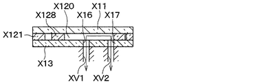
ここで、マイクロバルブX1の構成について更に説明する。マイクロバルブX1は、図4、図5に示すように、いずれも半導体である第1外層X11、中間層X12、第2外層X13を備えたMEMSである。MEMSは、Micro Electro Mechanical Systemsの略称である。第1外層X11、中間層X12、第2外層X13は、それぞれが同じ外形を有する長方形の板形状の部材であり、第1外層X11、中間層X12、第2外層X13の順に積層されている。すなわち、中間層X12が、第1外層X11と第2外層X13に両側から挟まれている。第1外層X11、中間層X12、第2外層X13のうち、第2外層X13が、バルブケーシングX2の底壁に最も近い側に配置される。後述する第1外層X11、中間層X12、第2外層X13の構造は、化学的エッチング等の半導体製造プロセスによって形成される。 Here, the configuration of the micro valve X1 will be further described. As shown in FIGS. 4 and 5, the microvalve X1 is a MEMS having a first outer layer X11, an intermediate layer X12, and a second outer layer X13, all of which are semiconductors. MEMS is an abbreviation for Micro Electro Mechanical Systems. The first outer layer X11, the intermediate layer X12, and the second outer layer X13 are rectangular plate-shaped members having the same outer shape, and are laminated in the order of the first outer layer X11, the intermediate layer X12, and the second outer layer X13. That is, the intermediate layer X12 is sandwiched between the first outer layer X11 and the second outer layer X13 from both sides. Of the first outer layer X11, the intermediate layer X12, and the second outer layer X13, the second outer layer X13 is arranged on the side closest to the bottom wall of the valve casing X2. The structures of the first outer layer X11, the intermediate layer X12, and the second outer layer X13, which will be described later, are formed by a semiconductor manufacturing process such as chemical etching.
第1外層X11は、表面に非導電性の酸化膜のある導電性の半導体部材である。第1外層X11には、図4に示すように、表裏に貫通する2つの貫通孔X14、X15が形成されている。この貫通孔X14、X15に、それぞれ、電気配線X6、X7のマイクロバルブX1側端が挿入される。 The first outer layer X11 is a conductive semiconductor member having a non-conductive oxide film on its surface. As shown in FIG. 4, the first outer layer X11 is formed with two through holes X14 and X15 penetrating the front and back surfaces. The microvalve X1 side ends of the electrical wirings X6 and X7 are inserted into the through holes X14 and X15, respectively.
第2外層X13は、表面に非導電性の酸化膜のある導電性の半導体部材である。第2外層X13には、図4、図6、図7に示すように、表裏に貫通する第1冷媒孔X16、第2冷媒孔X17が形成されている。図7に示すように、第1冷媒孔X16はバルブケーシングX2の第1連通孔XV1に連通し、第2冷媒孔X17はバルブケーシングX2の第2連通孔XV2に連通する。第1冷媒孔X16、第2冷媒孔X17の各々の水力直径は、例えば0.1mm以上かつ3mm以下であるが、これに限定されない。 The second outer layer X13 is a conductive semiconductor member having a non-conductive oxide film on its surface. As shown in FIGS. 4, 6 and 7, the second outer layer X13 is formed with a first refrigerant hole X16 and a second refrigerant hole X17 penetrating the front and back surfaces. As shown in FIG. 7, the first refrigerant hole X16 communicates with the first communication hole XV1 of the valve casing X2, and the second refrigerant hole X17 communicates with the second communication hole XV2 of the valve casing X2. The hydraulic diameters of the first refrigerant holes X16 and the second refrigerant holes X17 are, for example, 0.1 mm or more and 3 mm or less, but are not limited thereto.
中間層X12は、導電性の半導体部材である。中間層X12は、第1外層X11の酸化膜と第2外層X13の酸化膜とに接触するので、第1外層X11と第2外層X13とも電気的に非導通である。中間層X12は、図6に示すように、第1固定部X121、第2固定部X122、複数本の第1リブX123、複数本の第2リブX124、スパインX125、アームX126、梁X127、可動部X128を有している。 The intermediate layer X12 is a conductive semiconductor member. Since the intermediate layer X12 comes into contact with the oxide film of the first outer layer X11 and the oxide film of the second outer layer X13, both the first outer layer X11 and the second outer layer X13 are electrically non-conducting. As shown in FIG. 6, the intermediate layer X12 has a first fixed portion X121, a second fixed portion X122, a plurality of first ribs X123, a plurality of second ribs X124, a spine X125, an arm X126, a beam X127, and a movable layer. It has a part X128.
第1固定部X121は、第1外層X11、第2外層X13に対して固定された部材である。第1固定部X121は、第2固定部X122、第1リブX123、第2リブX124、スパインX125、アームX126、梁X127、可動部X128を同じ1つの冷媒室X19内に囲むように形成されている。冷媒室X19は、第1固定部X121、第1外層X11、第2外層X13によって囲まれた室である。第1固定部X121、第1外層X11、第2外層X13は、全体として基部に対応する。なお、電気配線X6、X7は複数の第1リブX123および複数の第2リブX124の温度を変化させて変位させるための電気配線である。 The first fixing portion X121 is a member fixed to the first outer layer X11 and the second outer layer X13. The first fixed portion X121 is formed so as to surround the second fixed portion X122, the first rib X123, the second rib X124, the spine X125, the arm X126, the beam X127, and the movable portion X128 in the same one refrigerant chamber X19. There is. The refrigerant chamber X19 is a chamber surrounded by a first fixing portion X121, a first outer layer X11, and a second outer layer X13. The first fixed portion X121, the first outer layer X11, and the second outer layer X13 correspond to the base portion as a whole. The electrical wirings X6 and X7 are electrical wirings for changing the temperature of the plurality of first ribs X123 and the plurality of second ribs X124 to displace them.
第1固定部X121の第1外層X11および第2外層X13に対する固定は、冷媒がこの冷媒室X19から第1冷媒孔X16、第2冷媒孔X17以外を通ってマイクロバルブX1から漏出することを抑制するような形態で、行われている。 Fixing the first fixing portion X121 to the first outer layer X11 and the second outer layer X13 suppresses the refrigerant from leaking from the refrigerant chamber X19 through the other than the first refrigerant hole X16 and the second refrigerant hole X17. It is done in such a way that it does.
第2固定部X122は、第1外層X11、第2外層X13に対して固定される。第2固定部X122は、第1固定部X121に取り囲まれると共に、第1固定部X121から離れて配置される。 The second fixing portion X122 is fixed to the first outer layer X11 and the second outer layer X13. The second fixed portion X122 is surrounded by the first fixed portion X121 and is arranged away from the first fixed portion X121.
複数本の第1リブX123、複数本の第2リブX124、スパインX125、アームX126、梁X127、可動部X128は、第1外層X11、第2外層X13に対して固定されておらず、第1外層X11、第2外層X13に対して変位可能である。 The plurality of first ribs X123, the plurality of second ribs X124, the spine X125, the arm X126, the beam X127, and the movable portion X128 are not fixed to the first outer layer X11 and the second outer layer X13, and are the first. It can be displaced with respect to the outer layer X11 and the second outer layer X13.
スパインX125は、中間層X12の矩形形状の短手方向に伸びる細長い棒形状を有している。スパインX125の長手方向の一端は、梁X127に接続されている。 The spine X125 has an elongated rod shape extending in the lateral direction in the rectangular shape of the intermediate layer X12. One end of the spine X125 in the longitudinal direction is connected to the beam X127.
複数本の第1リブX123は、スパインX125の長手方向に直交する方向におけるスパインX125の一方側に配置される。そして、複数本の第1リブX123は、スパインX125の長手方向に並んでいる。各第1リブX123は、細長い棒形状を有しており、温度に応じて伸縮可能となっている。 The plurality of first ribs X123 are arranged on one side of the spine X125 in a direction orthogonal to the longitudinal direction of the spine X125. The plurality of first ribs X123 are arranged in the longitudinal direction of the spine X125. Each first rib X123 has an elongated rod shape and can be expanded and contracted according to temperature.
各第1リブX123は、その長手方向の一端で第1固定部X121に接続され、他端でスパインX125に接続される。そして、各第1リブX123は、第1固定部X121側からスパインX125側に近付くほど、スパインX125の長手方向の梁X127側に向けてオフセットされるよう、スパインX125に対して斜行している。そして、複数の第1リブX123は、互いに対して平行に伸びている。 Each first rib X123 is connected to the first fixing portion X121 at one end in the longitudinal direction thereof and to the spine X125 at the other end. Each of the first ribs X123 is skewed with respect to the spine X125 so that the closer the first rib X123 is from the first fixed portion X121 side to the spine X125 side, the more the first rib X123 is offset toward the beam X127 side in the longitudinal direction of the spine X125. .. The plurality of first ribs X123 extend parallel to each other.
複数本の第2リブX124は、スパインX125の長手方向に直交する方向におけるスパインX125の他方側に配置される。そして、複数本の第2リブX124は、スパインX125の長手方向に並んでいる。各第2リブX124は、細長い棒形状を有しており、温度に応じて伸縮可能となっている。 The plurality of second ribs X124 are arranged on the other side of the spine X125 in a direction orthogonal to the longitudinal direction of the spine X125. The plurality of second ribs X124 are arranged in the longitudinal direction of the spine X125. Each second rib X124 has an elongated rod shape and can be expanded and contracted according to temperature.
各第2リブX124は、その長手方向の一端で第2固定部X122に接続され、他端でスパインX125に接続される。そして、各第2リブX124は、第2固定部X122側からスパインX125側に近付くほど、スパインX125の長手方向の梁X127側に向けてオフセットされるよう、スパインX125に対して斜行している。そして、複数の第2リブX124は、互いに対して平行に伸びている。 Each second rib X124 is connected to the second fixing portion X122 at one end in the longitudinal direction thereof and to the spine X125 at the other end. Each of the second ribs X124 is skewed with respect to the spine X125 so that the closer the second rib X124 is to the spine X125 side, the more the second rib X124 is offset toward the beam X127 side in the longitudinal direction of the spine X125. .. The plurality of second ribs X124 extend in parallel with each other.
複数本の第1リブX123、複数本の第2リブX124、スパインX125は、全体として、駆動部に対応する。 The plurality of first ribs X123, the plurality of second ribs X124, and the spine X125 correspond to the drive unit as a whole.
アームX126は、スパインX125と非直交かつ平行に伸びる細長い棒形状を有している。アームX126の長手方向の一端は梁X127に接続されており、他端は第1固定部X121に接続されている。 The arm X126 has an elongated rod shape extending non-orthogonally and parallel to the spine X125. One end of the arm X126 in the longitudinal direction is connected to the beam X127, and the other end is connected to the first fixing portion X121.
梁X127は、スパインX125およびアームX126に対して約90°で交差する方向に伸びる細長い棒形状を有している。梁X127の一端は、可動部X128に接続されている。アームX126と梁X127は、全体として、増幅部に対応する。 The beam X127 has an elongated rod shape extending in a direction intersecting the spine X125 and the arm X126 at about 90 °. One end of the beam X127 is connected to the movable portion X128. The arm X126 and the beam X127 correspond to the amplification unit as a whole.
アームX126と梁X127の接続位置XP1、スパインX125と梁X127の接続位置XP2、梁X127と可動部X128の接続位置XP3は、梁X127の長手方向に沿って、この順に並んでいる。そして、第1固定部X121とアームX126との接続点をヒンジXP0とすると、中間層X12の板面に平行な面内におけるヒンジXP0から接続位置XP2までの直線距離よりも、ヒンジXP0から接続位置XP3までの直線距離の方が、長い。 The connection position XP1 of the arm X126 and the beam X127, the connection position XP2 of the spine X125 and the beam X127, and the connection position XP3 of the beam X127 and the movable portion X128 are arranged in this order along the longitudinal direction of the beam X127. Then, assuming that the connection point between the first fixed portion X121 and the arm X126 is the hinge XP0, the connection position from the hinge XP0 is more than the linear distance from the hinge XP0 to the connection position XP2 in the plane parallel to the plate surface of the intermediate layer X12. The straight line distance to XP3 is longer.
可動部X128は、その外形が、梁X127の長手方向に対して概ね90°の方向に伸びる矩形形状を有している。この可動部X128は、冷媒室X19内において梁X127と一体に動くことができる。そして、可動部X128は、そのように動くことで、ある位置にいるときには第1冷媒孔X16と第2冷媒孔X17とを冷媒室X19を介して連通させ、また別の位置にいるときには第1冷媒孔X16と第2冷媒孔X17とを冷媒室X19内において遮断する。可動部X128は、中間層X12の表裏に貫通する貫通孔X120を囲む枠形状となっている。したがって、貫通孔X120も、可動部X128と一体的に移動する。貫通孔X120は、冷媒室X19の一部である。 The movable portion X128 has a rectangular shape whose outer shape extends in a direction of approximately 90 ° with respect to the longitudinal direction of the beam X127. The movable portion X128 can move integrally with the beam X127 in the refrigerant chamber X19. Then, by moving in this way, the movable portion X128 communicates the first refrigerant hole X16 and the second refrigerant hole X17 through the refrigerant chamber X19 when it is in a certain position, and when it is in another position, it is the first. The refrigerant hole X16 and the second refrigerant hole X17 are shut off in the refrigerant chamber X19. The movable portion X128 has a frame shape surrounding a through hole X120 penetrating the front and back of the intermediate layer X12. Therefore, the through hole X120 also moves integrally with the movable portion X128. The through hole X120 is a part of the refrigerant chamber X19.
また、第1固定部X121のうち、複数の第1リブX123と接続する部分の近傍の第1印加点X129には、図4に示した第1外層X11の貫通孔X14を通った電気配線X6のマイクロバルブX1側端が接続される。また、第2固定部X122の第2印加点X130には、図4に示した第1外層X11の貫通孔X15を通った電気配線X7のマイクロバルブX1側端が接続される。 Further, at the first application point X129 in the vicinity of the portion of the first fixed portion X121 connected to the plurality of first ribs X123, the electrical wiring X6 passing through the through hole X14 of the first outer layer X11 shown in FIG. The microvalve X1 side end of is connected. Further, the microvalve X1 side end of the electric wiring X7 passing through the through hole X15 of the first outer layer X11 shown in FIG. 4 is connected to the second application point X130 of the second fixing portion X122.
[バルブモジュールX0の作動]
ここで、バルブモジュールX0の作動について説明する。マイクロバルブX1への通電時は、電気配線X6、X7から第1印加点X129、第2印加点X130に電圧が印加される。すると、複数の第1リブX123、複数の第2リブX124を電流が流れる。この電流によって、複数の第1リブX123、複数の第2リブX124が発熱してそれらの温度が上昇する。その結果、複数の第1リブX123、複数の第2リブX124の各々が、その長手方向に膨張する。
[Operation of valve module X0]
Here, the operation of the valve module X0 will be described. When the micro valve X1 is energized, a voltage is applied from the electrical wirings X6 and X7 to the first application point X129 and the second application point X130. Then, a current flows through the plurality of first ribs X123 and the plurality of second ribs X124. Due to this current, the plurality of first ribs X123 and the plurality of second ribs X124 generate heat and their temperatures rise. As a result, each of the plurality of first ribs X123 and the plurality of second ribs X124 expands in the longitudinal direction thereof.
このような、温度上昇に伴う熱的な膨張の結果、複数の第1リブX123、複数の第2リブX124は、スパインX125を接続位置XP2側に付勢する。付勢されたスパインX125は、接続位置XP2において、梁X127を押す。このように、接続位置XP2は付勢位置に対応する。その結果、梁X127とアームX126から成る部材は、ヒンジXP0を支点として、接続位置XP2を力点として、一体に姿勢を変える。その結果、梁X127のアームX126とは反対側の端部に接続された可動部X128も、その長手方向の、スパインX125が梁X127を押す側に、移動する。その移動の結果、可動部X128は、図8、図9に示すように、移動方向の先端が第1固定部X121に当接する位置に到達する。以下、可動部X128のこの位置を通電時位置という。 As a result of such thermal expansion due to the temperature rise, the plurality of first ribs X123 and the plurality of second ribs X124 urge the spine X125 toward the connection position XP2. The urged spine X125 pushes the beam X127 at the connection position XP2. In this way, the connection position XP2 corresponds to the urging position. As a result, the member composed of the beam X127 and the arm X126 integrally changes its posture with the hinge XP0 as a fulcrum and the connection position XP2 as a force point. As a result, the movable portion X128 connected to the end of the beam X127 opposite to the arm X126 also moves in the longitudinal direction to the side where the spine X125 pushes the beam X127. As a result of the movement, the movable portion X128 reaches a position where the tip in the moving direction abuts on the first fixed portion X121 as shown in FIGS. 8 and 9. Hereinafter, this position of the movable portion X128 is referred to as an energized position.
このように、梁X127およびアームX126は、ヒンジXP0を支点とし、接続位置XP2を力点とし、接続位置XP3を作用点とする梃子として機能する。上述の通り、中間層X12の板面に平行な面内におけるヒンジXP0から接続位置XP2までの直線距離よりも、ヒンジXP0から接続位置XP3までの直線距離の方が、長い。したがって、力点である接続位置XP2の移動量よりも、作用点である接続位置XP3の移動量の方が大きくなる。したがって、熱的な膨張による変位量が、梃子によって増幅されて可動部X128に伝わる。 As described above, the beam X127 and the arm X126 function as a lever having the hinge XP0 as a fulcrum, the connection position XP2 as a force point, and the connection position XP3 as an action point. As described above, the linear distance from the hinge XP0 to the connection position XP3 is longer than the linear distance from the hinge XP0 to the connection position XP2 in the plane parallel to the plate surface of the intermediate layer X12. Therefore, the amount of movement of the connection position XP3, which is the point of action, is larger than the amount of movement of the connection position XP2, which is the point of effort. Therefore, the amount of displacement due to thermal expansion is amplified by the lever and transmitted to the movable portion X128.
図8、図9に示すように、可動部X128が通電時位置にある場合、貫通孔X120が中間層X12の板面に直交する方向に第1冷媒孔X16、第2冷媒孔X17と重なる。その場合、第1冷媒孔X16と第2冷媒孔X17とが冷媒室X19の一部である貫通孔X120を介して連通する。この結果、第1連通孔XV1と第2連通孔XV2との間で、第1冷媒孔X16、貫通孔X120、第2冷媒孔X17を介した、冷媒の流通が可能となる。つまり、マイクロバルブX1が開弁する。 As shown in FIGS. 8 and 9, when the movable portion X128 is in the energized position, the through hole X120 overlaps with the first refrigerant hole X16 and the second refrigerant hole X17 in the direction orthogonal to the plate surface of the intermediate layer X12. In that case, the first refrigerant hole X16 and the second refrigerant hole X17 communicate with each other through the through hole X120 which is a part of the refrigerant chamber X19. As a result, the refrigerant can flow between the first communication hole XV1 and the second communication hole XV2 through the first refrigerant hole X16, the through hole X120, and the second refrigerant hole X17. That is, the micro valve X1 opens.
このときの、マイクロバルブX1における冷媒の流路は、Uターン構造を有している。具体的には、冷媒は、マイクロバルブX1の一方側の面からマイクロバルブX1内に流入し、マイクロバルブX1内を通って、マイクロバルブX1の同じ側の面からマイクロバルブX1外に流出する。そして同様にバルブモジュールX0における冷媒の流路も、Uターン構造を有している。具体的には、冷媒は、バルブモジュールX0の一方側の面からバルブモジュールX0内に流入し、バルブモジュールX0内を通って、バルブモジュールX0の同じ側の面からバルブモジュールX0外に流出する。なお、中間層X12の板面に直交する方向は、第1外層X11、中間層X12、第2外層X13の積層方向である。 At this time, the flow path of the refrigerant in the micro valve X1 has a U-turn structure. Specifically, the refrigerant flows into the micro valve X1 from one surface of the micro valve X1, passes through the micro valve X1, and flows out of the micro valve X1 from the same surface of the micro valve X1. Similarly, the flow path of the refrigerant in the valve module X0 also has a U-turn structure. Specifically, the refrigerant flows into the valve module X0 from one surface of the valve module X0, passes through the valve module X0, and flows out of the valve module X0 from the same side surface of the valve module X0. The direction orthogonal to the plate surface of the intermediate layer X12 is the stacking direction of the first outer layer X11, the intermediate layer X12, and the second outer layer X13.
また、マイクロバルブX1への非通電時は、電気配線X6、X7から第1印加点X129、第2印加点X130への電圧印加が停止される。すると、複数の第1リブX123、複数の第2リブX124を電流が流れなくなり、複数の第1リブX123、複数の第2リブX124の温度が低下する。その結果、複数の第1リブX123、複数の第2リブX124の各々が、その長手方向に収縮する。 Further, when the micro valve X1 is not energized, the voltage application from the electrical wirings X6 and X7 to the first application point X129 and the second application point X130 is stopped. Then, the current stops flowing through the plurality of first ribs X123 and the plurality of second ribs X124, and the temperatures of the plurality of first ribs X123 and the plurality of second ribs X124 decrease. As a result, each of the plurality of first ribs X123 and the plurality of second ribs X124 contracts in the longitudinal direction thereof.
このような、温度低下に伴う熱的な収縮の結果、複数の第1リブX123、複数の第2リブX124は、スパインX125を接続位置XP2とは反対側に付勢する。付勢されたスパインX125は、接続位置XP2において、梁X127を引っ張る。その結果、梁X127とアームX126から成る部材は、ヒンジXP0を支点として、接続位置XP2を力点として、一体に姿勢を変える。その結果、梁X127のアームX126とは反対側の端部に接続された可動部X128も、その長手方向の、スパインX125が梁X127を引っ張る側に、移動する。その移動の結果、可動部X128は、図6、図7に示すように、第1固定部X121に当接しない位置に到達する。以下、可動部X128のこの位置を非通電時位置という。 As a result of such thermal contraction due to the temperature decrease, the plurality of first ribs X123 and the plurality of second ribs X124 urge the spine X125 to the side opposite to the connection position XP2. The urged spine X125 pulls the beam X127 at the connection position XP2. As a result, the member composed of the beam X127 and the arm X126 integrally changes its posture with the hinge XP0 as a fulcrum and the connection position XP2 as a force point. As a result, the movable portion X128 connected to the end of the beam X127 opposite to the arm X126 also moves in the longitudinal direction to the side where the spine X125 pulls the beam X127. As a result of the movement, the movable portion X128 reaches a position where it does not abut on the first fixed portion X121 as shown in FIGS. 6 and 7. Hereinafter, this position of the movable portion X128 is referred to as a non-energized position.
図6、図7に示すように、可動部X128が非通電時位置にある場合、貫通孔X120は、中間層X12の板面に直交する方向に第1冷媒孔X16と重なるが、当該方向に第2冷媒孔X17とは重ならない。第2冷媒孔X17は、中間層X12の板面に直交する方向に可動部X128と重なる。つまり、第2冷媒孔X17は、可動部X128によって塞がれる。この場合、第1冷媒孔X16と第2冷媒孔X17とが冷媒室X19内において遮断される。この結果、第1連通孔XV1と第2連通孔XV2との間で、第1冷媒孔X16、第2冷媒孔X17を介した冷媒の流通は阻害される。つまり、マイクロバルブX1が閉弁する。 As shown in FIGS. 6 and 7, when the movable portion X128 is in the non-energized position, the through hole X120 overlaps with the first refrigerant hole X16 in the direction orthogonal to the plate surface of the intermediate layer X12, but in that direction. It does not overlap with the second refrigerant hole X17. The second refrigerant hole X17 overlaps the movable portion X128 in the direction orthogonal to the plate surface of the intermediate layer X12. That is, the second refrigerant hole X17 is closed by the movable portion X128. In this case, the first refrigerant hole X16 and the second refrigerant hole X17 are shut off in the refrigerant chamber X19. As a result, the flow of the refrigerant between the first communication hole XV1 and the second communication hole XV2 through the first refrigerant hole X16 and the second refrigerant hole X17 is hindered. That is, the micro valve X1 is closed.
上述の通り、マイクロバルブX1は、非通電時に閉弁し、通電時に開弁する。マイクロバルブX1は、固定絞り23を含む冷媒流路31を開閉する。これにより、弁装置22は、吸引側流路21を流れる冷媒の流量をゼロとそれよりも多い流量との一方に調整することができる。マイクロバルブX1の開弁時に、冷媒が固定絞り23を流れる。これにより、弁装置22は、吸引側流路21を流れる冷媒を減圧させることができる。
As described above, the micro valve X1 closes when it is not energized and opens when it is energized. The micro valve X1 opens and closes the
次に、本実施形態の効果について説明する。 Next, the effect of this embodiment will be described.
図10に示す比較例1の弁装置J22は、従来の弁装置の一例である。比較例1の弁装置J22では、開閉弁としての電磁弁J22aと固定絞りJ22bとが一体化されている。電磁弁J22aは、電気エネルギーを機械運動に変換するソレノイド部J1と、流路を開閉する弁部J2とを有する。ソレノイド部J1にはコイルJ3、ピストンJ4が含まれる。弁部J2には、弁体J5および弁座J6が含まれる。 The valve device J22 of Comparative Example 1 shown in FIG. 10 is an example of a conventional valve device. In the valve device J22 of Comparative Example 1, the solenoid valve J22a as an on-off valve and the fixed throttle J22b are integrated. The solenoid valve J22a has a solenoid portion J1 that converts electrical energy into mechanical motion, and a valve portion J2 that opens and closes a flow path. The solenoid unit J1 includes a coil J3 and a piston J4. The valve portion J2 includes a valve body J5 and a valve seat J6.
固定絞りJ22bおよび弁座J6は、流路形成部材J30に形成されている。流路形成部材J30は、内部に冷媒流路J31を形成している。冷媒流路J31は、第1流路J32と、第2流路J33と、固定絞りJ22bとを含む。第1流路J32は、流路形成部材J30の冷媒入口部J30aに連通している。第2流路J33は、流路形成部材J30の冷媒出口部J30bに連通している。第1流路J32と第2流路33とは、弁座J6の内側に形成された弁座開口部および固定絞りJ22bを介して、連通している。
The fixed throttle J22b and the valve seat J6 are formed on the flow path forming member J30. The flow path forming member J30 forms a refrigerant flow path J31 inside. The refrigerant flow path J31 includes a first flow path J32, a second flow path J33, and a fixed throttle J22b. The first flow path J32 communicates with the refrigerant inlet portion J30a of the flow path forming member J30. The second flow path J33 communicates with the refrigerant outlet portion J30b of the flow path forming member J30. The first flow path J32 and the
コイルJ3の通電状態に応じて、ピストンJ4が移動する。ピストンJ4の移動によって、ピストンJ4の端部に設けられた弁体J5が移動する。弁体J5が弁座J6に接したり、弁体J5が弁座J6から離れたりすることで、冷媒流路J31が開閉される。 The piston J4 moves according to the energized state of the coil J3. The movement of the piston J4 causes the valve body J5 provided at the end of the piston J4 to move. When the valve body J5 comes into contact with the valve seat J6 or the valve body J5 separates from the valve seat J6, the refrigerant flow path J31 is opened and closed.
比較例1の弁装置J22は、クールボックスの内部に収容されている。クールボックスは、車室内に設置されるため、クールボックスの全体の大きさは限られている。電磁弁J0は体格が大きいため、比較例1の弁装置J22の体格は大きい。このため、クールボックスの容量は、弁装置J22の体積分、小さくなっている。 The valve device J22 of Comparative Example 1 is housed inside a cool box. Since the cool box is installed in the passenger compartment, the overall size of the cool box is limited. Since the solenoid valve J0 has a large body size, the valve device J22 of Comparative Example 1 has a large body size. Therefore, the capacity of the cool box is smaller than the volume of the valve device J22.
これに対して、本実施形態によれば、弁装置22の弁機構として、マイクロバルブX1が用いられている。マイクロバルブX1は、電磁弁J0と比べて容易に小型化できる。その理由の1つは、マイクロバルブX1が上述の通り半導体チップにより形成されているということである。また、上述の通り、梃子を利用して熱的な膨張による変位量が増幅されることも、そのような梃子を利用しない電磁弁と比べた小型化に寄与する。
On the other hand, according to the present embodiment, the micro valve X1 is used as the valve mechanism of the
このため、比較例1の弁装置J22と比較して、弁装置22の体格を小さくすることができる。すなわち、比較例1の弁装置J22と比較して、弁装置22の体積を減少させることができる。弁装置22の体積減少分を、クールボックスの容量増大分に充てることができる。よって、クールボックスの容量を増大させることができる。
Therefore, the body size of the
また、梃子を利用しているので、熱的な膨張による変位量を可動部X128の移動量より抑えることができる。したがって、可動部X128を駆動するための消費電力も低減することができる。マイクロバルブX1の消費電力が小さいので、弁装置22が省電力化される。
Further, since the lever is used, the amount of displacement due to thermal expansion can be suppressed from the amount of movement of the movable portion X128. Therefore, the power consumption for driving the movable portion X128 can also be reduced. Since the power consumption of the micro valve X1 is small, the power consumption of the
また、電磁弁の駆動時における衝撃音を無くすことができるので、騒音を低減することができる。また、マイクロバルブX1が軽量であることから、弁装置22が軽量化される。
Further, since the impact noise when the solenoid valve is driven can be eliminated, the noise can be reduced. Further, since the micro valve X1 is lightweight, the
(第2実施形態)
図11に示すように、本実施形態では、冷凍サイクル装置10は、第1実施形態の弁装置22に替えて、弁装置40を備えている。冷凍サイクル装置10の他の構成は、第1実施形態と同じである。
(Second Embodiment)
As shown in FIG. 11, in the present embodiment, the
弁装置40は、マイクロバルブX1を含む。弁装置40は、第2蒸発器24に流入する冷媒の流量を調整するとともに、第2蒸発器24に流入する冷媒を減圧させる流量調整部である。冷媒の流量を調整することには、流量をゼロにすることが含まれる。
The
図12に示すように、弁装置40は、流路形成部材41と、バルブモジュールX0とを有する。
As shown in FIG. 12, the
流路形成部材41は、内部に冷媒流路42を形成している。冷媒流路42は、第1流路43と、第2流路44とを含む。第1流路43は、流路形成部材41の冷媒入口部41aに連通している。第2流路44は、流路形成部材41の冷媒出口部41bに連通している。第1流路43と第2流路44とは、流路形成部材41の内部で、直接、連通しておらず、バルブモジュールX0の流路を介して、連通している。流路形成部材41は、金属製の部材である。
The flow
バルブモジュールX0は、流路形成部材41に接続されている。バルブモジュールX0の構成は、第1実施形態のバルブモジュールX0と同じである。第1突出部X21は、流路形成部材41に形成された第1開口部45に嵌め込まれている。第1開口部45は、第1流路43に連通している。このため、第1連通孔XV1は、第1流路43に連通している。第2突出部X22は、流路形成部材41に形成された第2開口部46に嵌め込まれている。第2開口部46は、第2流路44に連通している。このため、第2連通孔XV22は、第2流路44に連通している。
The valve module X0 is connected to the flow
ただし、本実施形態では、図8中の第1印加点X129、第2印加点X130に印加される電圧がPWM制御される。PWM制御は、通電と非通電とを繰り返し切り替える制御である。このとき、Duty比が大きいほど、供給される電力が大きい。Duty比は、ある期間に占める通電時間の割合である。電力が大きいほど、温度が高くなり、熱膨張量が大きくなる。このため、Duty比が大きいほど、非通電時に対する通電時の移動量が大きくなる。よって、PWM制御により、可動部X128の位置を全閉位置から全開位置の間で連続的に変更することができる。 However, in the present embodiment, the voltage applied to the first application point X129 and the second application point X130 in FIG. 8 is PWM controlled. The PWM control is a control that repeatedly switches between energized and de-energized. At this time, the larger the duty ratio, the larger the power supplied. Duty ratio is the ratio of energizing time to a certain period. The larger the electric power, the higher the temperature and the larger the amount of thermal expansion. Therefore, the larger the duty ratio, the larger the amount of movement during energization with respect to the non-energization. Therefore, the position of the movable portion X128 can be continuously changed from the fully closed position to the fully open position by PWM control.
このため、図13に示すように、マイクロバルブX1は、Duty比を0%から100%までの間で連続的に変更することで、流路の開度を0%から100%までの間で直線的に変更することができる。流路の開度が0%よりも大きいときの流路断面積は、冷媒を減圧させる大きさである。このように、マイクロバルブX1は、冷媒流路を開閉するとともに、冷媒流路が開状態のときに冷媒流路を流れる冷媒を減圧させ、かつ、冷媒を減圧させるときの冷媒流路の流路開度の変更が可能な可変絞りとして用いられている。これにより、弁装置40は、吸引側流路21を流れる冷媒の流量を、0から最大値までの範囲内で、任意の大きさに調整することができるとともに、吸引側流路21を流れる冷媒を減圧させることができる。
Therefore, as shown in FIG. 13, the micro valve X1 continuously changes the duty ratio between 0% and 100%, thereby increasing the opening degree of the flow path between 0% and 100%. It can be changed linearly. The flow path cross-sectional area when the opening degree of the flow path is larger than 0% is a size that reduces the pressure of the refrigerant. In this way, the micro valve X1 opens and closes the refrigerant flow path, reduces the pressure of the refrigerant flowing through the refrigerant flow path when the refrigerant flow path is open, and reduces the pressure of the refrigerant flow path. It is used as a variable aperture whose opening can be changed. As a result, the
本実施形態によれば、マイクロバルブX1の流路開度を調整することで、第2蒸発器24を流れる冷媒の流量を所望の流量に調整することができる。このため、第2蒸発器24を流れる冷媒の流量の調整によって、第2蒸発器24の冷却能力を調整することができる。これにより、クールボックスの庫内の温度を目標温度にすることができる。
According to this embodiment, the flow rate of the refrigerant flowing through the
(第3実施形態)
図14に示すように、本実施形態では、冷凍サイクル装置10は、第1実施形態の弁装置22に替えて、弁装置50を備えている。弁装置50は、第2蒸発器24に流入する冷媒の流量を調整するとともに、第2蒸発器24に流入する冷媒を減圧させる流量調整部である。冷媒の流量を調整することには、流量をゼロにすることが含まれる。
(Third Embodiment)
As shown in FIG. 14, in the present embodiment, the
弁装置50は、冷媒が流入する冷媒入口部51aと、冷媒が流出する冷媒出口部51bとを有する。冷媒入口部51aは、分岐部20の2つの冷媒出口部の一方の冷媒出口部側に接続されている。冷媒出口部51bは、第2蒸発器24の冷媒入口側に接続されている。
The
弁装置50は、1つの電磁弁50aと、1つの固定絞り50bと、1つのマイクロバルブX1とを含む。電磁弁50aは、弁装置50の冷媒入口部51aから弁装置50の冷媒出口部51bに至る冷媒流路を開閉する開閉弁である。固定絞り50bは、冷媒入口部51aから流入した冷媒を減圧膨張させる。マイクロバルブX1は、冷媒入口部51aから流入した冷媒を固定絞り50bを迂回させて冷媒出口部51bに導く迂回流路を開閉するとともに、迂回流路が開状態のときに迂回流路を流れる冷媒を減圧させる。冷凍サイクル装置10の他の構成は、第1実施形態と同じである。
The
弁装置50の具体的な構成について説明する。図15に示すように、弁装置50では、電磁弁50aと、固定絞り50bと、マイクロバルブX1とが一体として構成されている。具体的には、弁装置50は、流路形成部材51と、ソレノイド部52と、弁体53と、バルブモジュールX0とを有している。
A specific configuration of the
流路形成部材51は、金属製の部材である。流路形成部材51は、内部に冷媒が流れる冷媒流路511を形成している。冷媒流路511は、第1流路512と、第2流路513と、弁室514と、弁座流路515と、固定絞り50bとを含む。第1流路512と第2流路513とは、弁室514、弁座流路515および固定絞り50bを介して、連通している。
The flow
流路形成部材51には、冷媒入口部51aと、冷媒出口部51bとが形成されている。第1流路512は、冷媒入口部51aに連通している。第2流路513は、冷媒出口部51bに連通している。
The flow
弁室514には、弁体53が配置されている。弁座流路515は、弁座516の内側の流路であって、弁体53によって開閉される流路である。固定絞り50bは、第1流路512と第2流路513とのそれぞれよりも流路断面積が小さな流路である。
A
流路形成部材51は、弁室514を形成する弁室形成部54と、固定絞り50bを形成する固定絞り形成部55とを有する。固定絞り形成部55は、弁室514の中に位置する。固定絞り形成部55は、固定絞り50bの他に、弁座流路515と、第2流路513の一部とを形成している。固定絞り形成部55の弁座流路515側の端部が弁座516となっている。
The flow
ソレノイド部52は、電気エネルギーを機械運動に変換する。ソレノイド部52は、コイル521と、ピストン522とを含む。コイル521の通電状態に応じて、ピストン522は移動する。
The
弁体53は、ピストン522の端部に固定されている。弁体53は、合成ゴム製である。ピストン522の移動によって、弁体53は、弁座516に接したり、弁座516から離れたりする。すなわち、弁体53が弁座流路515を開閉する。ソレノイド部52と、弁体53と、弁座516とは、電磁弁50aを構成している。
The
図16に示すように、固定絞り形成部55には、第1貫通孔55aと第2貫通孔55bとが形成されている。弁室形成部54には、第3貫通孔54aと第4貫通孔54bとが形成されている。第1貫通孔55aと第3貫通孔54aとは、同軸上に配置されている。第2貫通孔55bと第4貫通孔54bとは、同軸上に配置されている。
As shown in FIG. 16, the fixed
バルブモジュールX0は、第1実施形態と同様に、マイクロバルブX1、バルブケーシングX2、封止部材X3、2本の電気配線X6、X7を有している。バルブモジュールX0は、第1実施形態と異なり、4つのOリングX4、X5、X8、X9を有している。 The valve module X0 has a micro valve X1, a valve casing X2, a sealing member X3, and two electrical wirings X6 and X7, as in the first embodiment. Unlike the first embodiment, the valve module X0 has four O-rings X4, X5, X8, and X9.
バルブモジュールX0は、流路形成部材51の外側に設けられている。バルブケーシングX2の第1突出部X21は、第1貫通孔55aと第3貫通孔54aとに、嵌めこまれている。第1突出部X21の先端は、第1貫通孔55aの内部に位置する。第1連通孔XV1は、第1貫通孔55aを介して、固定絞り50bの冷媒流れ上流側の弁座流路515に連通している。バルブケーシングX2の第2突出部X22は、第2貫通孔55bと第4貫通孔54bとに、嵌め込まれている。第2突出部X22の先端は、第2貫通孔55bの内部に位置する。第2連通孔XV2は、第2貫通孔55bを介して、固定絞り50bの冷媒流れ上流側の第2流路513に連通している。
The valve module X0 is provided on the outside of the flow
本実施形態では、流路形成部材51とバルブケーシングX2とが、全体として、冷媒入口部51aから冷媒出口部51bに至る冷媒流路を形成する流路形成部品に対応する。第1貫通孔55aと、第1連通孔XV1と、第2連通孔XV2と、第2貫通孔55bとが、全体として、冷媒入口部51aから流入した冷媒を固定絞り50bを迂回させて冷媒出口部51bに導く迂回流路に対応する。冷媒流路511と、第1貫通孔55aと、第1連通孔XV1と、第2連通孔XV2と、第2貫通孔55bとが、全体として、流量調整部の冷媒入口部から流量調整部の冷媒出口部に至る冷媒流路に対応する。
In the present embodiment, the flow
弁体53が弁座516から離れることで、電磁弁50aが開弁する。電磁弁50aが開弁し、かつ、マイクロバルブX1が閉弁しているとき、放熱器14から流出した冷媒は、分岐部20で分岐される。分岐された一方の冷媒は、エジェクタ16、第1蒸発器18を順に流れる。分岐された他方の冷媒は、弁装置50の冷媒入口部51aに流入する。冷媒入口部51aに流入した冷媒は、第1流路512、弁座流路515、固定絞り50b、第2流路513の順に流れた後、冷媒出口部51bから流出する。冷媒出口部51bから流出した冷媒は、第2蒸発器24を流れた後、エジェクタ16の吸引部16bに流入する。
When the
また、電磁弁50aが開弁し、かつ、マイクロバルブX1が開弁しているとき、上記の冷媒流れに加えて、マイクロバルブX1を通過する冷媒流れが形成される。すなわち、弁装置50の内部には、冷媒入口部51aから固定絞り50bを通過して冷媒出口部51bに到達する冷媒流れと、冷媒入口部51aから固定絞り50bを迂回して冷媒出口部51bに到達する冷媒流れとが形成される。マイクロバルブX1の開弁時の最小流路断面積は、冷媒を減圧膨張させる大きさに設定されている。このため、マイクロバルブX1で減圧膨張された冷媒と、固定絞り50bで減圧膨張された冷媒とが合流する。合流した冷媒が、冷媒出口部51bから流出する。冷媒出口部51bから流出した冷媒は、第2蒸発器24を流れた後、エジェクタ16の吸引部16bに流入する。
Further, when the
電磁弁50aが閉弁しているとき、放熱器14から流出した冷媒は、分岐部20で分岐されず、エジェクタ16、第1蒸発器18を順に流れる。第2蒸発器24には、冷媒が流れない。
When the
本実施形態によっても、第1実施形態と同様の効果が得られる。さらに、本実施形態によれば、下記の効果が得られる。 The same effect as that of the first embodiment can be obtained by this embodiment as well. Further, according to the present embodiment, the following effects can be obtained.
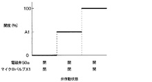
上記の説明の通り、図17に示すように、弁装置50は、流路を開閉するとともに、流路の開度を二段階で変更することができる。電磁弁50aとマイクロバルブX1との両方が開弁しているときの弁装置50の流路開度を100%の開度とする。電磁弁50aが閉じているときの弁装置50の流路開度を0%とする。この場合、電磁弁50aが開弁し、マイクロバルブX1が閉弁しているときの開度は、0%と100%との間の中間開度A1である。
As described above, as shown in FIG. 17, the
本実施形態では、クールボックスの通常の使用時に、電磁弁50aを開弁し、マイクロバルブX1を閉弁する。クールボックスの急速冷却時等の第2蒸発器24の冷却能力を増大させる場合に、電磁弁50aを開弁した状態で、マイクロバルブX1を開弁する。これにより、マイクロバルブX1の閉弁時と比較して、弁装置50から流出する冷媒の流量を増大させることができ、第2蒸発器24を流れる冷媒の流量を増大させることができる。このため、第2蒸発器24の冷却能力を増大させることができる。
In the present embodiment, the
(第4実施形態)
図18に示すように、本実施形態では、弁装置50は、1つの電磁弁50aと、1つの固定絞り50bと、2つのマイクロバルブX1、Y1とを含む。固定絞り50bおよび2つのマイクロバルブX1、Y1のそれぞれは、冷媒入口部51aと冷媒出口部51bとの間において、互いに並列に接続されている。マイクロバルブY1の構成は、マイクロバルブX1と同じである。弁装置50の他の構成は、第3実施形態と同じである。
(Fourth Embodiment)
As shown in FIG. 18, in the present embodiment, the
図19に示すように、弁装置50は、流路を開閉するとともに、流路の開度を三段階で変更することができる。電磁弁50aおよびマイクロバルブX1、Y1の全部が開弁しているときの弁装置50の流路開度を100%の開度とする。電磁弁50aが閉じているときの弁装置50の流路開度を0%とする。この場合、電磁弁50aが開弁し、マイクロバルブX1およびマイクロバルブY1が閉弁しているときの開度は、0%と100%との間の第1中間開度A2である。電磁弁50aが開弁し、マイクロバルブX1が開弁し、マイクロバルブY1が閉弁しているときの開度は、0%と100%との間の第2中間開度A3である。第2中間開度A3は、第1中間開度A2よりも大きい。
As shown in FIG. 19, the
本実施形態においても、第1実施形態と同様の効果が得られる。また、本実施形態によれば、マイクロバルブX1、Y1のそれぞれを開閉することで、第2蒸発器24を流れる冷媒の流量を三段階で調整することができる。これにより、第2蒸発器24の冷却能力を調整することができる。
Also in this embodiment, the same effect as that of the first embodiment can be obtained. Further, according to the present embodiment, the flow rate of the refrigerant flowing through the
なお、固定絞り50bおよび3つ以上の複数のマイクロバルブが、冷媒入口部51aと冷媒出口部51bとの間において、互いに並列に接続されていてもよい。これによれば、複数のマイクロバルブのそれぞれの開閉によって、減圧膨張された冷媒の流量を、多段階に調整することができる。
The fixed
(第5実施形態)
図20に示すように、本実施形態の冷凍サイクル装置10Aは、車両に搭載されるエジェクタ式冷凍サイクル装置である。冷凍サイクル装置10Aは、図示しない車室の内部の冷房を行う。
(Fifth Embodiment)
As shown in FIG. 20, the
冷凍サイクル装置10Aは、圧縮機12と、放熱器14と、膨張弁15と、エジェクタ16と、気液分離器60と、蒸発器62と、バイパス流路64と、逆止弁66と、弁装置68とを備える。これらの冷凍サイクル装置10Aの構成部品は、蒸気圧縮式の冷凍サイクルを構成している。
The
膨張弁15は、蒸発器62から流出した冷媒の過熱度に応じて、膨張弁15を通過する冷媒の流量を調整する。
The
気液分離器60は、エジェクタ16から流出した冷媒を、気相冷媒と液相冷媒とに分離する。気液分離器60の気相冷媒の出口側は、圧縮機12の冷媒吸入側に接続されている。気液分離器60の液相冷媒の出口側は、蒸発器62の冷媒入口側に接続されている。これにより、気液分離器60は、分離された気相冷媒を圧縮機12に流入させ、分離された液相冷媒を蒸発器62に流入させる。
The gas-
蒸発器62は、気液分離器60から流出した液相冷媒と車室の内部へ送られる空気との熱交換により、空気を冷却するとともに、冷媒を蒸発させる。蒸発器62の冷媒出口側は、エジェクタ16の吸引部16bに接続されている。これにより、蒸発器62は、蒸発後の冷媒を吸引部16bに流入させる。
The
バイパス流路64は、放熱器14から流出した冷媒を、エジェクタ16および気液分離器60を迂回させて、蒸発器62に導く流路である。バイパス流路64の一端は、冷媒流路のうち放熱器14と膨張弁15との間に位置する第1接続部63に接続されている。バイパス流路64の他端は、冷媒流路のうち気液分離器60と蒸発器62の上流側との間に位置する第2接続部65に接続されている。本実施形態では、バイパス流路64と、第2接続部65から吸引部16bまでの冷媒流路とが、全体として、吸引部16bに向かって冷媒が流れる吸引側流路に対応する。
The
逆止弁66は、気液分離器60の液相冷媒側と第2接続部65とをつなぐ冷媒流路の途中に設けられている。逆止弁66は、気液分離器60の液相冷媒出口から第2接続部65に向かう冷媒流れを許容し、第2接続部65から気液分離器60の液相冷媒出口に向かう冷媒流れを阻止する。
The
弁装置68は、バイパス流路64に設けられている。弁装置68は、マイクロバルブX1を含む。弁装置68は、バイパス流路64を流れる冷媒の流量を調整するとともに、バイパス流路64を流れる冷媒を減圧させる流量調整部である。冷媒の流量を調整することには、冷媒の流量を0とすることが含まれる。
The
図21に示すように、弁装置68は、バルブモジュールX0と、ブロック体70とを有する。バルブモジュールX0は、ブロック体70に接続されている。バルブモジュールX0の構成は、第1実施形態と同じである。
As shown in FIG. 21, the
ブロック体70は、バルブモジュールX0と、第1配管71と、第2配管72とを接続する接続部材である。第1配管71は、バイパス流路64の一部を構成する。第2配管72は、バイパス流路64の他の一部を構成する。
The
ブロック体70の内部には、第1流路73と第2流路74とが形成されている。ブロック体70の内部では、第1流路73と第2流路74とは連通していない。ブロック体70には、第1流路73に連通する第1開口部73aと第2開口部73bとが形成されている。ブロック体70には、第2流路74に連通する第3開口部74aと第4開口部74bとが形成されている。第3開口部74aは、第1開口部73aの隣りに配置されている。第1開口部73a、第3開口部74aのそれぞれに、バルブモジュールX0の第1突出部X21、第2突出部X22が嵌めこまれている。第2開口部73bに、第1配管71が挿入されている。第4開口部74bに、第2配管72が挿入されている。これにより、第1配管71の内部の流路71aは、第1流路73を介して、第1連通孔XV1と連通している。第2配管72の内部の流路72aは、第2流路74を介して、第2連通孔XV2と連通している。
A
マイクロバルブX1が開弁しているとき、第1連通孔XV1と第2連通孔XV2とが連通する。これにより、第1配管71の内部の流路71aと、第2配管72の内部の流路72aとが連通する。マイクロバルブX1が閉弁しているとき、第1連通孔XV1と第2連通孔XV2とが連通しない。これにより、第1配管71の内部の流路71aと、第2配管72の内部の流路72aとが連通する。このように、マイクロバルブX1は、バイパス流路64を開閉する。
When the micro valve X1 is open, the first communication hole XV1 and the second communication hole XV2 communicate with each other. As a result, the
さらに、マイクロバルブX1は、第2実施形態と同様に、バイパス流路64が開状態のときに冷媒を減圧させ、かつ、冷媒を減圧させるときの流路の開度の変更が可能である。このように、弁装置68は、バイパス流路64を流れる冷媒の流量を0から最大値までの間で任意の大きさに調整することができるとともに、バイパス流路64を流れる冷媒を減圧させることができる。
Further, as in the second embodiment, the micro valve X1 can reduce the pressure of the refrigerant when the
次に、冷凍サイクル装置10Aの作動について説明する。
Next, the operation of the
エジェクタ16のノズル部16aに流入する冷媒の流量が所定流量よりも多い場合、マイクロバルブX1は閉弁する。エジェクタ16のノズル部16aに流入する冷媒の流量が所定流量よりも多い場合とは、例えば、圧縮機12の回転数が所定回転数よりも大きい場合である。
When the flow rate of the refrigerant flowing into the
この場合、圧縮機12の作動によって高温高圧の冷媒が圧縮機12から吐出される。圧縮機12から吐出された高温高圧の冷媒は、放熱器14で放熱される。放熱器14で放熱された冷媒は、膨張弁15によって減圧膨張された後、エジェクタ16のノズル部16aに流入する。ノズル部16aに流入した冷媒は、ノズル部16aから噴射されることで、減圧膨張される。ノズル部16aから噴射された冷媒は、吸引部16bから流入した冷媒とともに、昇圧部16cに流入する。昇圧部16cに流入した冷媒は、昇圧された後、昇圧部16cから流出する。昇圧部16cから流出した冷媒は、気液分離器60に流入する。
In this case, the operation of the
気液分離器60に流入した冷媒は、気相冷媒と液相冷媒とに分離される。分離された気相冷媒は、圧縮機12に吸入される。分離された液相冷媒は、蒸発器62に流入する。蒸発器62で、冷媒が蒸発することで、車室の内部の空気が冷却される。これにより、車室の内部の冷房が行われる。蒸発器62から流出した冷媒は、吸引部16bに流入する。
The refrigerant flowing into the gas-
ここで、蒸発器62を流れる冷媒の流量は、昇圧部16cでの冷媒の昇圧量に依存している。この昇圧量は、エジェクタ16を流れる冷媒の流量に依存している。このため、エジェクタ16を流れる冷媒の流量が少ない条件では、この昇圧量が少なく、蒸発器62を冷媒が流れない場合がある。具体的には、昇圧量が、配管を流れることによる冷媒の圧力損失量と同じ場合、気液分離器60から吸引部16bに向かう冷媒流れが生じない。
Here, the flow rate of the refrigerant flowing through the
そこで、ノズル部16aに流入する冷媒の流量が所定流量よりも少ない場合、マイクロバルブX1は開弁する。ノズル部16aに流入する冷媒の流量が所定流量よりも少ない場合とは、例えば、圧縮機12の回転数が所定回転数よりも小さい場合である。この所定回転数は、弁装置68が閉状態のときに蒸発器62に冷媒が流れないときの圧縮機12の回転数に基づいて設定される。
Therefore, when the flow rate of the refrigerant flowing into the
マイクロバルブX1が開弁することで、圧縮機12の作用によって、放熱器14を流出した冷媒がバイパス流路64を流れる。このとき、冷媒がマイクロバルブX1を通過することで、冷媒が減圧される。減圧された冷媒が、蒸発器62に流入する。蒸発器62で蒸発した冷媒は、吸引部16b、気液分離器60を介して、圧縮機12に吸入される。
When the micro valve X1 is opened, the refrigerant flowing out of the
このように、サイクルを流れる冷媒の流量が所定流量よりも少ない場合、マイクロバルブX1が開弁する。これにより、冷媒の流量が少ない条件時に蒸発器62に冷媒が流れないことを回避することができる。
As described above, when the flow rate of the refrigerant flowing through the cycle is smaller than the predetermined flow rate, the micro valve X1 is opened. As a result, it is possible to prevent the refrigerant from flowing to the
従来では、バイパス流路64を開閉する弁として、感温室と流れる冷媒との圧力差を利用した機械式の弁が用いられている。これに対して、本実施形態では、弁装置68の弁機構として、マイクロバルブX1が用いられている。マイクロバルブX1は、このような従来の機械式の弁と比較して、小型化が容易である。このため、弁装置68の弁機構として、従来の機械式の弁が用いられる場合と比較して、弁装置68を小型化することができる。
Conventionally, as a valve for opening and closing the
さらに、本実施形態では、マイクロバルブX1の開度を調整して、蒸発器62に流れる冷媒の流量を調整することができる。このため、冷房負荷に応じて、蒸発器62に流れる冷媒の流量を適正な流量に調整することができる。
Further, in the present embodiment, the opening degree of the micro valve X1 can be adjusted to adjust the flow rate of the refrigerant flowing through the
換言すると、弁装置68の流路断面積が固定される場合では、所定の条件のときに、蒸発器62を流れる冷媒の流量が適正な流量となるように、流路断面積が設定される。これに対して、本実施形態によれば、幅広い条件で、蒸発器62を流れる冷媒の流量が適正な流量となるように、弁装置68の流路断面積を変更することができる。
In other words, when the flow path cross-sectional area of the
なお、本実施形態では、マイクロバルブX1の流路開度が任意の大きさに変更可能である。しかしながら、マイクロバルブX1は、開閉のみを行うようになっていてもよい。 In this embodiment, the flow path opening degree of the micro valve X1 can be changed to an arbitrary size. However, the micro valve X1 may only open and close.
また、本実施形態では、冷媒の流量が所定流量よりも少ない場合、弁装置68が開状態とされる。しかしながら、他の条件の場合に、弁装置68が開状態とされてもよい。
Further, in the present embodiment, when the flow rate of the refrigerant is smaller than the predetermined flow rate, the
(第6実施形態)
本実施形態は、第1実施形態のマイクロバルブX1が、故障検知機能を有するよう変更されている。具体的には、マイクロバルブX1は、第1実施形態と同じ構成に加え、図22、図23に示すように、故障検知部X50を備えている。
(Sixth Embodiment)
In this embodiment, the micro valve X1 of the first embodiment is modified to have a failure detection function. Specifically, the micro valve X1 includes a failure detection unit X50 as shown in FIGS. 22 and 23, in addition to the same configuration as that of the first embodiment.
故障検知部X50は、中間層X12のアームX126に形成されたブリッジ回路を含む。ブリッジ回路は、図23のように接続された4つのゲージ抵抗を含んでいる。つまり、故障検知部X50は、ダイヤフラムに相当するアームX126の歪みに応じて抵抗が変化するブリッジ回路である。つまり、故障検知部X50は半導体ピエゾ抵抗式の歪みセンサである。故障検知部X50は、電気的絶縁膜を介して、アームX126と導通しないように、アームX126に接続されていてもよい。 The failure detection unit X50 includes a bridge circuit formed on the arm X126 of the intermediate layer X12. The bridge circuit includes four gauge resistors connected as shown in FIG. That is, the failure detection unit X50 is a bridge circuit whose resistance changes according to the distortion of the arm X126 corresponding to the diaphragm. That is, the failure detection unit X50 is a semiconductor piezo resistance type distortion sensor. The failure detection unit X50 may be connected to the arm X126 via an electrical insulating film so as not to be electrically connected to the arm X126.
このブリッジ回路の対角にある2つの入力端子に配線X51、X52が接続される。そして、配線X51、X52から当該入力端子に、定電流発生用の電圧が印加される。この配線X51、X52は、電気配線X6、X7を介してマイクロバルブX1に印加される電圧(すなわち、マイクロバルブ駆動電圧)から分岐して上記2つの入力端子まで伸びている。 Wiring X51 and X52 are connected to two input terminals on the diagonal of this bridge circuit. Then, a voltage for generating a constant current is applied from the wirings X51 and X52 to the input terminal. The wirings X51 and X52 branch from the voltage applied to the microvalve X1 (that is, the microvalve driving voltage) via the electrical wirings X6 and X7 and extend to the above two input terminals.
また、このブリッジ回路の別の対角にある2つの出力端子に、配線X53、X54が接続される。そして、アームX126の歪み量に応じたレベルの電圧信号が配線X53、X54から出力される。この電圧信号は、後述する通り、マイクロバルブX1が正常に作動しているか否かを判別するための情報として使用される。配線X53、X54から出力される電圧信号は、マイクロバルブX1の外部にある制御装置X55に入力される。 Further, the wirings X53 and X54 are connected to two output terminals on different diagonals of the bridge circuit. Then, a voltage signal at a level corresponding to the amount of distortion of the arm X126 is output from the wirings X53 and X54. As will be described later, this voltage signal is used as information for determining whether or not the microvalve X1 is operating normally. The voltage signals output from the wirings X53 and X54 are input to the control device X55 outside the microvalve X1.
この制御装置X55は、例えば、車両用空調装置において圧縮機、送風機、エアミックスドア、内外気切替ドア等の作動を制御するエアコンECUであってもよい。あるいは、この制御装置X55は、車両において、車速、燃料残量、電池残量等を表示するメータECUであってもよい。 The control device X55 may be, for example, an air conditioner ECU that controls the operation of a compressor, a blower, an air mix door, an inside / outside air switching door, or the like in a vehicle air conditioner. Alternatively, the control device X55 may be a meter ECU that displays the vehicle speed, the remaining fuel amount, the remaining battery amount, and the like in the vehicle.
アームX126の歪み量に応じた電圧信号を制御装置X55が配線X53、X54を介して取得すると、制御装置X55は、当該電圧信号に応じて、マイクロバルブX1の故障の有無を検知する。検知対象の故障としては、例えば、アームX126が折れる故障、可動部X128と第1外層X11または第2外層X13との間に微小な異物が挟まって可動部X128が動かなくなる故障、等がある。 When the control device X55 acquires a voltage signal corresponding to the amount of distortion of the arm X126 via the wirings X53 and X54, the control device X55 detects the presence or absence of failure of the microvalve X1 according to the voltage signal. Examples of the failure to be detected include a failure in which the arm X126 breaks, a failure in which a minute foreign substance is caught between the movable portion X128 and the first outer layer X11 or the second outer layer X13, and the movable portion X128 becomes immobile.
複数本の第1リブX123および複数本の第2リブX124の伸縮に応じて、梁X127および可動部X128が変位する際、アームX126の歪み量が変化する。したがって、アームX126の歪み量に応じた電圧信号から、可動部X128の位置を推定できる。一方、マイクロバルブX1が正常であれば、電気配線X6、X7からマイクロバルブX1への通電量と可動部X128の位置との間にも相関関係がある。この通電量は、マイクロバルブX1を制御するための制御量である。 When the beam X127 and the movable portion X128 are displaced according to the expansion and contraction of the plurality of first ribs X123 and the plurality of second ribs X124, the amount of strain of the arm X126 changes. Therefore, the position of the movable portion X128 can be estimated from the voltage signal corresponding to the amount of distortion of the arm X126. On the other hand, if the micro valve X1 is normal, there is also a correlation between the amount of electricity supplied from the electrical wirings X6 and X7 to the micro valve X1 and the position of the movable portion X128. This energized amount is a controlled amount for controlling the micro valve X1.
制御装置X55は、このことを利用して、マイクロバルブX1の故障の有無を検知する。つまり、制御装置X55は、配線X53、X54からの電圧信号から、あらかじめ定められた第1マップに基づいて、可動部X128の位置を算出する。そして、あらかじめ定められた第2マップに基づいて、可動部X128の位置から、正常時において当該位置を実現するために必要な電気配線X6、X7からマイクロバルブX1への供給電力を算出する。これら第1マップ、第2マップは、制御装置X55の不揮発性メモリに記録されている。不揮発性メモリは、非遷移的実体的記憶媒体である。第1マップにおける電圧信号のレベルと位置との対応関係は、あらかじめ実験等によって定められてもよい。また、第2マップにおける位置と供給電力との対応関係も、あらかじめ実験等によって定められてもよい。 The control device X55 utilizes this to detect the presence or absence of a failure of the micro valve X1. That is, the control device X55 calculates the position of the movable portion X128 from the voltage signals from the wirings X53 and X54 based on the predetermined first map. Then, based on the second map determined in advance, the power supplied from the electric wirings X6 and X7 required to realize the position in the normal state to the micro valve X1 is calculated from the position of the movable portion X128. These first map and second map are recorded in the non-volatile memory of the control device X55. Non-volatile memory is a non-transitional substantive storage medium. The correspondence between the level and the position of the voltage signal in the first map may be determined in advance by an experiment or the like. Further, the correspondence relationship between the position and the supplied power in the second map may be determined in advance by an experiment or the like.
そして、制御装置X55は、算出された電力と、実際に電気配線X6、X7からマイクロバルブX1へ供給されている電力とを比較する。そして、制御装置X55は、前者の電力と後者の電力の差の絶対値が許容値を超えていれば、マイクロバルブX1が故障していると判定し、許容値を超えていなければ、マイクロバルブX1が正常であると判定する。そして、制御装置X55は、マイクロバルブX1が故障していると判定した場合に、所定の故障報知制御を行う。 Then, the control device X55 compares the calculated electric power with the electric power actually supplied from the electric wirings X6 and X7 to the microvalve X1. Then, the control device X55 determines that the micro valve X1 is out of order if the absolute value of the difference between the former power and the latter power exceeds the permissible value, and if it does not exceed the permissible value, the micro valve It is determined that X1 is normal. Then, when it is determined that the micro valve X1 is out of order, the control device X55 performs predetermined failure notification control.
制御装置X55は、この故障報知制御においては、車内の人に報知を行う報知装置X56を作動させる。例えば、制御装置X55は、警告ランプを点灯させてもよい。また、制御装置X55は、画像表示装置に、マイクロバルブX1に故障が発生したことを示す画像を表示させてもよい。これによって、車両の乗員は、マイクロバルブX1の故障に気付くことができる。 In this failure notification control, the control device X55 operates a notification device X56 that notifies a person in the vehicle. For example, the control device X55 may turn on the warning lamp. Further, the control device X55 may cause the image display device to display an image indicating that a failure has occurred in the micro valve X1. As a result, the occupant of the vehicle can notice the failure of the micro valve X1.
また、制御装置X55は、この故障報知制御においては、車両内の記憶装置に、マイクロバルブX1に故障が発生したことを示す情報を記録してもよい。この記憶装置は、非遷移的実体的記憶媒体である。これにより、マイクロバルブX1の故障を記録に残すことができる。 Further, in this failure notification control, the control device X55 may record information indicating that a failure has occurred in the micro valve X1 in the storage device in the vehicle. This storage device is a non-transitional substantive storage medium. As a result, the failure of the micro valve X1 can be recorded.
また、制御装置X55は、マイクロバルブX1が故障していると判定した場合は、通電停止制御を行う。通電停止制御では、制御装置X55は、電気配線X6、X7からマイクロバルブX1への通電を停止させる。このように、マイクロバルブX1の故障時にマイクロバルブX1への通電を停止することで、マイクロバルブX1の故障時の安全性を高めることができる。 Further, when the control device X55 determines that the micro valve X1 is out of order, the control device X55 performs energization stop control. In the energization stop control, the control device X55 stops the energization from the electric wires X6 and X7 to the micro valve X1. In this way, by stopping the energization of the micro valve X1 when the micro valve X1 fails, the safety of the micro valve X1 at the time of failure can be enhanced.
以上のように、故障検知部X50が、マイクロバルブX1が正常に作動しているか否かを判別するための電圧信号を出力することで、制御装置X55は、マイクロバルブX1の故障の有無を容易に判別することができる。 As described above, the failure detection unit X50 outputs a voltage signal for determining whether or not the microvalve X1 is operating normally, so that the control device X55 can easily determine whether or not the microvalve X1 has a failure. Can be determined.
また、この電圧信号は、アームX126の歪み量に応じた信号である。したがって、電気配線X6、X7からマイクロバルブX1への通電量とこの電圧信号との関係に基づいて、マイクロバルブX1の故障の有無を容易に判別することができる。 Further, this voltage signal is a signal corresponding to the amount of distortion of the arm X126. Therefore, it is possible to easily determine whether or not the microvalve X1 has a failure based on the relationship between the amount of electricity supplied from the electrical wirings X6 and X7 to the microvalve X1 and this voltage signal.
なお、本実施形態では、ブリッジ回路を構成する抵抗の変化に基づいてマイクロバルブX1が故障しているか否かが判定されている。しかし、他の方法として、静電容量の変化に基づいてマイクロバルブX1が故障しているか否かが判定されてもよい。この場合、ブリッジ回路の代わりに容量成分を形成する複数の電極がアームX126に形成される。アームX126の歪み量と複数の電極間の静電容量の間は相関関係がある。したがって、制御装置は、この複数の電極間の静電容量の変化に基づいて、マイクロバルブX1が故障しているか否かを判定できる。 In the present embodiment, it is determined whether or not the microvalve X1 is out of order based on the change in the resistance constituting the bridge circuit. However, as another method, it may be determined whether or not the microvalve X1 has failed based on the change in capacitance. In this case, a plurality of electrodes forming a capacitive component are formed on the arm X126 instead of the bridge circuit. There is a correlation between the amount of strain in the arm X126 and the capacitance between the plurality of electrodes. Therefore, the control device can determine whether or not the microvalve X1 has failed based on the change in capacitance between the plurality of electrodes.
(他の実施形態)
(1)第1実施形態では、流路形成部材30の冷媒流路31に、固定絞り23が含まれている。しかし、冷媒流路31に、固定絞り23が含まれていなくてもよい。この場合、マイクロバルブX1が有する流路、例えば、第1冷媒孔X16、第2冷媒孔X17が、固定絞りとして機能する。
(Other embodiments)
(1) In the first embodiment, the
(2)第1実施形態等では、電気配線X6、X7からマイクロバルブX1への通電が停止したとき、マイクロバルブX1は閉弁状態となる。しかし、必ずしもこのようになっておらずともよい。例えば、電気配線X6、X7からマイクロバルブX1への通電が停止したとき、マイクロバルブX1は開弁状態となってもよい。 (2) In the first embodiment or the like, when the energization from the electrical wirings X6 and X7 to the microvalve X1 is stopped, the microvalve X1 is closed. However, this does not necessarily have to be the case. For example, when the energization of the electric wires X6 and X7 to the microvalve X1 is stopped, the microvalve X1 may be opened.
(3)上記各実施形態では、複数本の第1リブX123、複数本の第2リブX124は、半導体材料で構成されている。しかし、これらの部材は、通電されることで発熱し、その発熱によって自らの温度が上昇することで膨張する金属材料等の他の材料から構成されていてもよい。また、これらの部材は、温度が変化すると、変形する形状記憶材料から構成されていてもよい。この場合、駆動部は、その熱的な変形によって変位する。 (3) In each of the above embodiments, the plurality of first ribs X123 and the plurality of second ribs X124 are made of a semiconductor material. However, these members may be made of other materials such as a metal material that generates heat when energized and expands when its own temperature rises due to the heat generation. Further, these members may be made of a shape memory material that deforms when the temperature changes. In this case, the drive unit is displaced due to its thermal deformation.
(4)上記各実施形態では、冷凍サイクル装置10、10Aは、膨張弁15を備えている。しかし、冷凍サイクル装置10、10Aは、膨張弁15を備えていなくてもよい。この場合、エジェクタ16のノズル部16aによって、冷媒が減圧膨張される。
(4) In each of the above embodiments, the
(5)マイクロバルブX1の形状やサイズは、上記実施形態で示したものに限られない。マイクロバルブX1は、極微少流量制御可能で、かつ、流路内に存在する微小ゴミを詰まらせないような水力直径の第1冷媒孔X16、第2冷媒孔X17を有していればよい。 (5) The shape and size of the micro valve X1 are not limited to those shown in the above embodiment. The micro valve X1 may have a first refrigerant hole X16 and a second refrigerant hole X17 having a hydraulic diameter that can control a very small flow rate and do not clog minute dust existing in the flow path.
(6)本発明は上記した実施形態に限定されるものではなく、特許請求の範囲に記載した範囲内において適宜変更が可能であり、様々な変形例や均等範囲内の変形をも包含する。また、上記各実施形態は、互いに無関係なものではなく、組み合わせが明らかに不可な場合を除き、適宜組み合わせが可能である。また、上記各実施形態において、実施形態を構成する要素は、特に必須であると明示した場合および原理的に明らかに必須であると考えられる場合等を除き、必ずしも必須のものではないことは言うまでもない。また、上記各実施形態において、実施形態の構成要素の個数、数値、量、範囲等の数値が言及されている場合、特に必須であると明示した場合および原理的に明らかに特定の数に限定される場合等を除き、その特定の数に限定されるものではない。また、上記各実施形態において、構成要素等の材質、形状、位置関係等に言及するときは、特に明示した場合および原理的に特定の材質、形状、位置関係等に限定される場合等を除き、その材質、形状、位置関係等に限定されるものではない。 (6) The present invention is not limited to the above-described embodiment, and can be appropriately modified within the scope of claims, and includes various modifications and modifications within an equal range. Further, the above-described embodiments are not unrelated to each other, and can be appropriately combined unless the combination is clearly impossible. Further, in each of the above embodiments, it goes without saying that the elements constituting the embodiment are not necessarily essential except when it is clearly stated that they are essential and when they are clearly considered to be essential in principle. stomach. Further, in each of the above embodiments, when numerical values such as the number, numerical values, quantities, and ranges of the constituent elements of the embodiment are mentioned, when it is clearly stated that they are particularly essential, and in principle, the number is clearly limited to a specific number. It is not limited to the specific number except when it is done. Further, in each of the above embodiments, when referring to the material, shape, positional relationship, etc. of the constituent elements, etc., except when specifically specified or when the material, shape, positional relationship, etc. are limited to a specific material, shape, positional relationship, etc. in principle. , The material, shape, positional relationship, etc. are not limited.
(まとめ)
上記各実施形態の一部または全部で示された第1の観点によれば、エジェクタ式冷凍サイクル装置は、冷媒を圧縮して吐出する圧縮機と、圧縮機から吐出された冷媒を放熱させる放熱器と、放熱器から流出した冷媒を噴出させるノズル部、ノズル部から噴出された冷媒の流れにより冷媒を吸引する吸引部、およびノズル部から噴出された冷媒と吸引部から吸引された冷媒とを混合して昇圧する昇圧部を含むエジェクタと、吸引部に流入する冷媒の流量を調整する弁部品を含む流量調整部とを備える。
(summary)
According to the first aspect shown in a part or all of the above embodiments, the ejector type refrigerating cycle apparatus includes a compressor that compresses and discharges the refrigerant and heat dissipation that dissipates the refrigerant discharged from the compressor. The container, the nozzle part that ejects the refrigerant flowing out of the radiator, the suction part that sucks the refrigerant by the flow of the refrigerant ejected from the nozzle part, and the refrigerant ejected from the nozzle part and the refrigerant sucked from the suction part. It includes an ejector including a boosting unit that mixes and boosts pressure, and a flow rate adjusting unit that includes a valve component that adjusts the flow rate of the refrigerant flowing into the suction unit.
弁部品は、冷媒が流通する冷媒室、冷媒室に連通する第1冷媒孔、および冷媒室に連通する第2冷媒孔が形成される基部と、自らの温度が変化すると変位する駆動部と、駆動部の温度の変化による変位を増幅する増幅部と、増幅部によって増幅された変位が伝達されて冷媒室内で動くことで、冷媒室を介した第1冷媒孔と第2冷媒孔との間の連通、遮断を切り替える可動部と、を有する。駆動部が温度の変化によって変位したときに、駆動部が付勢位置において増幅部を付勢することで、増幅部がヒンジを支点として変位するとともに、増幅部と可動部の接続位置で増幅部が可動部を付勢する。ヒンジから付勢位置までの距離よりも、ヒンジから接続位置までの距離の方が長い。 The valve parts include a refrigerant chamber through which the refrigerant flows, a first refrigerant hole communicating with the refrigerant chamber, a base forming a second refrigerant hole communicating with the refrigerant chamber, and a drive unit that displaces when its own temperature changes. The amplification unit that amplifies the displacement due to the change in the temperature of the drive unit and the displacement amplified by the amplification unit are transmitted and move in the refrigerant chamber, so that they are between the first refrigerant hole and the second refrigerant hole via the refrigerant chamber. It has a movable part that switches between communication and interruption. When the drive unit is displaced due to a change in temperature, the drive unit biases the amplification unit at the urging position, so that the amplification unit is displaced with the hinge as the fulcrum, and the amplification unit is displaced at the connection position between the amplification unit and the movable unit. Bounces the moving parts. The distance from the hinge to the connection position is longer than the distance from the hinge to the urging position.
また、第2の観点によれば、エジェクタ式冷凍サイクル装置は、放熱器から流出した冷媒を一方の冷媒と他方の冷媒とに分岐させる分岐部と、冷媒を蒸発させる第1蒸発器と、冷媒を蒸発させる第2蒸発器とを備える。一方の冷媒がノズル部、昇圧部、第1蒸発器の順に流れるように、分岐部、エジェクタおよび第1蒸発器は接続されている。他方の冷媒が流量調整部、第2蒸発器、吸引部の順に流れるように、分岐部、流量調整部、第2蒸発器およびエジェクタは接続されている。流量調整部は、第2蒸発器に流入する冷媒の流量を調整するとともに、第2蒸発器に流入する冷媒を減圧させる。このように、第1の観点の具体的な構成として、第2の観点の構成を採用することができる。 Further, according to the second viewpoint, the ejector type refrigerating cycle device includes a branch portion for branching the refrigerant flowing out from the radiator into one refrigerant and the other refrigerant, a first evaporator for evaporating the refrigerant, and a refrigerant. It is provided with a second evaporator for evaporating. The branch portion, the ejector, and the first evaporator are connected so that one of the refrigerants flows in the order of the nozzle portion, the boosting portion, and the first evaporator. The branch portion, the flow rate adjusting portion, the second evaporator, and the ejector are connected so that the other refrigerant flows in the order of the flow rate adjusting portion, the second evaporator, and the suction portion. The flow rate adjusting unit adjusts the flow rate of the refrigerant flowing into the second evaporator and reduces the pressure of the refrigerant flowing into the second evaporator. As described above, the configuration of the second viewpoint can be adopted as the specific configuration of the first viewpoint.
また、第3の観点によれば、流量調整部は、固定絞りを含む冷媒流路を形成する流路形成部材を有する。弁部品は、冷媒流路を開閉する。このように、第2の観点の具体的な構成として、第3の観点の構成を採用することができる。 Further, according to the third aspect, the flow rate adjusting unit has a flow path forming member for forming a refrigerant flow path including a fixed throttle. The valve component opens and closes the refrigerant flow path. As described above, the configuration of the third viewpoint can be adopted as the specific configuration of the second viewpoint.
また、第4の観点によれば、流量調整部は、冷媒流路を形成する流路形成部材を有する。弁部品は、冷媒流路を開閉するとともに、冷媒流路が開状態のときに冷媒流路を流れる冷媒を減圧させ、かつ、冷媒を減圧させるときの流路の開度の変更が可能である。 Further, according to the fourth aspect, the flow rate adjusting unit has a flow path forming member for forming a refrigerant flow path. The valve component can open and close the refrigerant flow path, reduce the pressure of the refrigerant flowing through the refrigerant flow path when the refrigerant flow path is open, and change the opening degree of the flow path when the refrigerant is reduced in pressure. ..
このように、第2の観点の具体的な構成として、第4の観点の構成を採用することができる。これによれば、弁部品が冷媒を減圧させるときの流路の開度を変更することで、第2蒸発器に流入する冷媒の流量を、0から最大値までの範囲内で、任意の大きさに調整することができる。 As described above, the configuration of the fourth viewpoint can be adopted as the specific configuration of the second viewpoint. According to this, by changing the opening degree of the flow path when the valve component depressurizes the refrigerant, the flow rate of the refrigerant flowing into the second evaporator can be set to an arbitrary size within a range of 0 to the maximum value. It can be adjusted.
また、第5の観点によれば、流量調整部は、流量調整部の冷媒入口部から流量調整部の冷媒出口部に至る冷媒流路を形成する流路形成部品と、冷媒流路を開閉する開閉弁とを有する。冷媒流路は、固定絞りと、冷媒入口部から流入した冷媒を固定絞りを迂回させて冷媒出口部に導くための迂回流路とを含む。弁部品は、迂回流路を開閉するとともに、迂回流路が開状態のときに迂回流路を流れる冷媒を減圧させる。 Further, according to the fifth viewpoint, the flow rate adjusting unit opens and closes the flow path forming component forming the refrigerant flow path from the refrigerant inlet portion of the flow rate adjusting section to the refrigerant outlet portion of the flow rate adjusting section, and the refrigerant flow path. It has an on-off valve. The refrigerant flow path includes a fixed throttle and a bypass flow path for guiding the refrigerant flowing from the refrigerant inlet portion by bypassing the fixed throttle portion to the refrigerant outlet portion. The valve component opens and closes the bypass flow path and reduces the pressure of the refrigerant flowing through the bypass flow path when the bypass flow path is open.
第2の観点の具体的な構成として、第4の観点の構成を採用することができる。これによれば、弁部品が迂回流路を開閉することで、第2蒸発器に流入する冷媒の流量を、0よりも大きい流量で段階的に調整することができる。 As a specific configuration of the second viewpoint, the configuration of the fourth viewpoint can be adopted. According to this, the flow rate of the refrigerant flowing into the second evaporator can be adjusted stepwise at a flow rate larger than 0 by opening and closing the bypass flow path of the valve component.
また、第6の観点によれば、エジェクタ式冷凍サイクル装置は、昇圧部から流出した冷媒を気相冷媒と液相冷媒とに分離し、分離した気相冷媒を圧縮機に流入させる気液分離器と、気液分離器で分離された液相冷媒を蒸発させ、蒸発後の冷媒を吸引部に流入させる蒸発器と、放熱器から流出した冷媒を、エジェクタおよび気液分離器を迂回させて、蒸発器に導くバイパス流路とを備える。流量調整部は、バイパス流路を流れる冷媒の流量を調整するとともに、バイパス流路を流れる冷媒を減圧させる。このように、第1の観点の具体的な構成として、第6の観点の構成を採用することができる。 Further, according to the sixth viewpoint, the ejector type refrigerating cycle apparatus separates the refrigerant flowing out from the boosting unit into the gas phase refrigerant and the liquid phase refrigerant, and causes the separated vapor phase refrigerant to flow into the compressor. The ejector and the gas-liquid separator are bypassed by the evaporator that evaporates the liquid-phase refrigerant separated by the gas-liquid separator and causes the evaporated refrigerant to flow into the suction unit, and the refrigerant that flows out from the radiator. , A bypass flow path leading to an evaporator is provided. The flow rate adjusting unit adjusts the flow rate of the refrigerant flowing through the bypass flow path and reduces the pressure of the refrigerant flowing through the bypass flow path. As described above, the configuration of the sixth viewpoint can be adopted as the specific configuration of the first viewpoint.
また、第7の観点によれば、弁部品は、当該弁部品が正常に作動しているか故障しているかを判別するための信号を出力する故障検知部を備えている。弁部品がこのような信号を出力することで、弁部品の故障の有無を容易に判別できる。 Further, according to the seventh aspect, the valve component includes a failure detection unit that outputs a signal for determining whether the valve component is operating normally or failing. When the valve component outputs such a signal, it is possible to easily determine whether or not the valve component has a failure.
また、第8の観点によれば、前記信号は、増幅部の歪み量に応じた信号である。このようになっていることで、この信号と弁部品を制御するための制御量との関係に基づいて、弁装置の故障の有無を判別することができる。 Further, according to the eighth viewpoint, the signal is a signal corresponding to the amount of distortion of the amplification unit. In this way, it is possible to determine the presence or absence of a failure of the valve device based on the relationship between this signal and the control amount for controlling the valve component.
また、第9の観点によれば、駆動部は、通電されることで発熱する。故障検知部は、弁部品が故障している場合に弁部品に対する通電を停止する装置に、信号を出力する。このように、弁部品の故障時に通電を停止することで、故障時の安全性を高めることができる。 Further, according to the ninth viewpoint, the drive unit generates heat when energized. The failure detection unit outputs a signal to a device that stops energization of the valve component when the valve component is out of order. In this way, by stopping the energization when the valve component fails, the safety at the time of failure can be enhanced.
また、第10の観点によれば、故障検知部は、弁部品が故障している場合に、人に報知を行う報知装置を作動させる装置に、信号を出力する。これにより、人は、弁部品の故障を知ることができる。 Further, according to the tenth viewpoint, the failure detection unit outputs a signal to a device that operates a notification device that notifies a person when a valve component is out of order. Thereby, a person can know the failure of the valve component.
また、第11の観点によれば、弁部品は、半導体チップによって構成されている。したがって、弁部品を小型に構成することができる。 Further, according to the eleventh viewpoint, the valve component is composed of a semiconductor chip. Therefore, the valve component can be made compact.
12 圧縮機
14 放熱器
16 エジェクタ
16b 吸引部
22 弁装置
40 弁装置
50 弁装置
68 弁装置
X1 マイクロバルブ
12
Claims (7)
冷媒を圧縮して吐出する圧縮機(12)と、
前記圧縮機から吐出された冷媒を放熱させる放熱器(14)と、
前記放熱器から流出した冷媒を噴出させるノズル部(16a)、前記ノズル部から噴出された冷媒の流れにより冷媒を吸引する吸引部(16b)、および前記ノズル部から噴出された冷媒と前記吸引部から吸引された冷媒とを混合して昇圧する昇圧部(16c)を含むエジェクタ(16)と、
前記吸引部に流入する冷媒の流量を調整する弁部品(X1)を含む流量調整部(50)とを備え、
前記弁部品は、
冷媒が流通する冷媒室(X19)、前記冷媒室に連通する第1冷媒孔(X16)、および前記冷媒室に連通する第2冷媒孔(X17)が形成される基部(X11、X121、X13)と、
自らの温度が変化すると変位する駆動部(X123、X124、X125)と、
前記駆動部の温度の変化による変位を増幅する増幅部(X126、X127)と、
前記増幅部によって増幅された変位が伝達されて前記冷媒室内で動くことで、前記冷媒室を介した前記第1冷媒孔と前記第2冷媒孔との間の連通、遮断を切り替える可動部(X128)と、を有し、
前記駆動部が温度の変化によって変位したときに、前記駆動部が付勢位置(XP2)において前記増幅部を付勢することで、前記増幅部がヒンジ(XP0)を支点として変位するとともに、前記増幅部と前記可動部の接続位置(XP3)で前記増幅部が前記可動部を付勢し、
前記ヒンジから前記付勢位置までの距離よりも、前記ヒンジから前記接続位置までの距離の方が長く、
前記エジェクタ式冷凍サイクル装置は、
前記放熱器から流出した冷媒を一方の冷媒と他方の冷媒とに分岐させる分岐部(20)と、
冷媒を蒸発させる第1蒸発器(18)と、
冷媒を蒸発させる第2蒸発器(24)とを備え、
前記一方の冷媒が前記ノズル部、前記昇圧部、前記第1蒸発器の順に流れるように、前記分岐部、前記エジェクタおよび前記第1蒸発器は接続されており、
前記他方の冷媒が前記流量調整部、前記第2蒸発器、前記吸引部の順に流れるように、前記分岐部、前記流量調整部、前記第2蒸発器および前記エジェクタは接続されており、
前記流量調整部(50)は、前記第2蒸発器に流入する冷媒の流量を調整するとともに、前記第2蒸発器に流入する冷媒を減圧させ、
前記流量調整部(50)は、前記流量調整部の冷媒入口部(51a)から前記流量調整部の冷媒出口部(51b)に至る冷媒流路を形成する流路形成部品(51、X2)と、
前記冷媒流路を開閉する開閉弁(50a)とを有し、
前記冷媒流路は、固定絞り(50b)と、前記冷媒入口部から流入した冷媒を前記固定絞りを迂回させて前記冷媒出口部に導くための迂回流路(XV1、XV2、55a、55b)とを含み、
前記弁部品は、前記迂回流路を開閉するとともに、前記迂回流路が開状態のときに前記迂回流路を流れる冷媒を減圧させる、エジェクタ式冷凍サイクル装置。 It is an ejector type refrigeration cycle device.
A compressor (12) that compresses and discharges the refrigerant,
A radiator (14) that dissipates heat from the refrigerant discharged from the compressor, and
A nozzle portion (16a) for ejecting the refrigerant flowing out of the radiator, a suction portion (16b) for sucking the refrigerant by the flow of the refrigerant ejected from the nozzle portion, and a refrigerant ejected from the nozzle portion and the suction portion. An ejector (16) including a booster (16c) that mixes and boosts the refrigerant sucked from the
A flow rate adjusting unit (50 ) including a valve component (X1) for adjusting the flow rate of the refrigerant flowing into the suction unit is provided.
The valve parts
Bases (X11, X121, X13) in which a refrigerant chamber (X19) through which a refrigerant flows, a first refrigerant hole (X16) communicating with the refrigerant chamber, and a second refrigerant hole (X17) communicating with the refrigerant chamber are formed. When,
Drive units (X123, X124, X125) that displace when their temperature changes,
Amplifying units (X126, X127) that amplify the displacement due to changes in the temperature of the driving unit, and
A movable unit (X128) that switches communication and interruption between the first refrigerant hole and the second refrigerant hole via the refrigerant chamber by transmitting the displacement amplified by the amplification unit and moving in the refrigerant chamber. ) And,
When the drive unit is displaced due to a change in temperature, the drive unit biases the amplification unit at the urging position (XP2), so that the amplification unit is displaced with the hinge (XP0) as a fulcrum and the above. The amplification unit urges the movable portion at the connection position (XP3) between the amplification unit and the movable portion.
Than the distance from the hinge to the urging position, towards the distance from the hinge to the connecting position is rather long,
The ejector type refrigeration cycle device is
A branch portion (20) that branches the refrigerant flowing out of the radiator into one refrigerant and the other refrigerant.
The first evaporator (18) that evaporates the refrigerant and
It is equipped with a second evaporator (24) that evaporates the refrigerant.
The branch portion, the ejector, and the first evaporator are connected so that one of the refrigerants flows in the order of the nozzle portion, the boosting portion, and the first evaporator.
The branch portion, the flow rate adjusting portion, the second evaporator, and the ejector are connected so that the other refrigerant flows in the order of the flow rate adjusting unit, the second evaporator, and the suction unit.
The flow rate adjusting unit (50) adjusts the flow rate of the refrigerant flowing into the second evaporator and reduces the pressure of the refrigerant flowing into the second evaporator.
The flow rate adjusting unit (50) includes a flow path forming component (51, X2) that forms a refrigerant flow path from the refrigerant inlet portion (51a) of the flow rate adjusting unit to the refrigerant outlet portion (51b) of the flow rate adjusting unit. ,
It has an on-off valve (50a) that opens and closes the refrigerant flow path.
The refrigerant flow path includes a fixed throttle (50b) and a bypass flow path (XV1, XV2, 55a, 55b) for guiding the refrigerant flowing from the refrigerant inlet portion to the refrigerant outlet portion by bypassing the fixed throttle portion. Including
The valve component is an ejector type refrigeration cycle device that opens and closes the bypass flow path and reduces the pressure of the refrigerant flowing through the bypass flow path when the bypass flow path is open.
冷媒を圧縮して吐出する圧縮機(12)と、
前記圧縮機から吐出された冷媒を放熱させる放熱器(14)と、
前記放熱器から流出した冷媒を噴出させるノズル部(16a)、前記ノズル部から噴出された冷媒の流れにより冷媒を吸引する吸引部(16b)、および前記ノズル部から噴出された冷媒と前記吸引部から吸引された冷媒とを混合して昇圧する昇圧部(16c)を含むエジェクタ(16)と、
前記吸引部に流入する冷媒の流量を調整する弁部品(X1)を含む流量調整部(68)とを備え、
前記弁部品は、
冷媒が流通する冷媒室(X19)、前記冷媒室に連通する第1冷媒孔(X16)、および前記冷媒室に連通する第2冷媒孔(X17)が形成される基部(X11、X121、X13)と、
自らの温度が変化すると変位する駆動部(X123、X124、X125)と、
前記駆動部の温度の変化による変位を増幅する増幅部(X126、X127)と、
前記増幅部によって増幅された変位が伝達されて前記冷媒室内で動くことで、前記冷媒室を介した前記第1冷媒孔と前記第2冷媒孔との間の連通、遮断を切り替える可動部(X128)と、を有し、
前記駆動部が温度の変化によって変位したときに、前記駆動部が付勢位置(XP2)において前記増幅部を付勢することで、前記増幅部がヒンジ(XP0)を支点として変位するとともに、前記増幅部と前記可動部の接続位置(XP3)で前記増幅部が前記可動部を付勢し、
前記ヒンジから前記付勢位置までの距離よりも、前記ヒンジから前記接続位置までの距離の方が長く、
前記エジェクタ式冷凍サイクル装置は、
前記昇圧部から流出した冷媒を気相冷媒と液相冷媒とに分離し、分離した気相冷媒を前記圧縮機に流入させる気液分離器(60)と、
前記気液分離器で分離された液相冷媒を蒸発させ、蒸発後の冷媒を前記吸引部に流入させる蒸発器(62)と、
前記放熱器から流出した冷媒を、前記エジェクタおよび前記気液分離器を迂回させて、前記蒸発器に導くバイパス流路(64)とを備え、
前記流量調整部(68)は、前記バイパス流路を流れる冷媒の流量を調整するとともに、前記バイパス流路を流れる冷媒を減圧させる、エジェクタ式冷凍サイクル装置。 It is an ejector type refrigeration cycle device.
A compressor (12) that compresses and discharges the refrigerant,
A radiator (14) that dissipates heat from the refrigerant discharged from the compressor, and
A nozzle portion (16a) for ejecting the refrigerant flowing out of the radiator, a suction portion (16b) for sucking the refrigerant by the flow of the refrigerant ejected from the nozzle portion, and a refrigerant ejected from the nozzle portion and the suction portion. An ejector (16) including a booster (16c) that mixes and boosts the refrigerant sucked from the
A flow rate adjusting unit (68 ) including a valve component (X1) for adjusting the flow rate of the refrigerant flowing into the suction unit is provided.
The valve parts
Bases (X11, X121, X13) in which a refrigerant chamber (X19) through which a refrigerant flows, a first refrigerant hole (X16) communicating with the refrigerant chamber, and a second refrigerant hole (X17) communicating with the refrigerant chamber are formed. When,
Drive units (X123, X124, X125) that displace when their temperature changes,
Amplifying units (X126, X127) that amplify the displacement due to changes in the temperature of the driving unit, and
A movable unit (X128) that switches communication and interruption between the first refrigerant hole and the second refrigerant hole via the refrigerant chamber by transmitting the displacement amplified by the amplification unit and moving in the refrigerant chamber. ) And,
When the drive unit is displaced due to a change in temperature, the drive unit biases the amplification unit at the urging position (XP2), so that the amplification unit is displaced with the hinge (XP0) as a fulcrum and the above. The amplification unit urges the movable portion at the connection position (XP3) between the amplification unit and the movable portion.
Than the distance from the hinge to the urging position, towards the distance from the hinge to the connecting position is rather long,
The ejector type refrigeration cycle device is
A gas-liquid separator (60) that separates the refrigerant flowing out from the booster into a gas-phase refrigerant and a liquid-phase refrigerant, and causes the separated vapor-phase refrigerant to flow into the compressor.
An evaporator (62) that evaporates the liquid-phase refrigerant separated by the gas-liquid separator and causes the evaporated refrigerant to flow into the suction unit.
A bypass flow path (64) for bypassing the ejector and the gas-liquid separator and guiding the refrigerant flowing out of the radiator to the evaporator is provided.
The flow rate adjusting unit (68) is an ejector type refrigeration cycle device that adjusts the flow rate of the refrigerant flowing through the bypass flow path and reduces the pressure of the refrigerant flowing through the bypass flow path.
前記故障検知部は、前記弁部品が故障している場合に前記弁部品に対する通電を停止する装置(X55)に、前記信号を出力する、請求項3または4に記載のエジェクタ式冷凍サイクル装置。 The drive unit generates heat when energized and generates heat.
The ejector type refrigeration cycle device according to claim 3 or 4 , wherein the failure detection unit outputs the signal to a device (X55) that stops energization of the valve component when the valve component is out of order.
Priority Applications (2)
| Application Number | Priority Date | Filing Date | Title |
|---|---|---|---|
| JP2019035228A JP6958582B2 (en) | 2019-02-28 | 2019-02-28 | Ejector type refrigeration cycle device |
| PCT/JP2020/007724 WO2020175548A1 (en) | 2019-02-28 | 2020-02-26 | Ejector-type refrigeration cycle device |
Applications Claiming Priority (1)
| Application Number | Priority Date | Filing Date | Title |
|---|---|---|---|
| JP2019035228A JP6958582B2 (en) | 2019-02-28 | 2019-02-28 | Ejector type refrigeration cycle device |
Publications (3)
| Publication Number | Publication Date |
|---|---|
| JP2020139682A JP2020139682A (en) | 2020-09-03 |
| JP2020139682A5 JP2020139682A5 (en) | 2021-04-15 |
| JP6958582B2 true JP6958582B2 (en) | 2021-11-02 |
Family
ID=72238616
Family Applications (1)
| Application Number | Title | Priority Date | Filing Date |
|---|---|---|---|
| JP2019035228A Active JP6958582B2 (en) | 2019-02-28 | 2019-02-28 | Ejector type refrigeration cycle device |
Country Status (2)
| Country | Link |
|---|---|
| JP (1) | JP6958582B2 (en) |
| WO (1) | WO2020175548A1 (en) |
Families Citing this family (1)
| Publication number | Priority date | Publication date | Assignee | Title |
|---|---|---|---|---|
| CN112377470B (en) * | 2020-11-11 | 2022-02-22 | 四川大学 | Improved central jet pump based on annular jet technology |
Family Cites Families (7)
| Publication number | Priority date | Publication date | Assignee | Title |
|---|---|---|---|---|
| JPS59142569U (en) * | 1983-03-16 | 1984-09-22 | 株式会社京浜精機製作所 | control valve |
| JP2002005334A (en) * | 2000-06-20 | 2002-01-09 | Nichigi Engineering Co Ltd | Anomaly detector for diaphragm valve device |
| JP4760181B2 (en) * | 2005-07-20 | 2011-08-31 | 株式会社デンソー | Ejector and ejector type cycle |
| JP2007218497A (en) * | 2006-02-16 | 2007-08-30 | Denso Corp | Ejector type refrigeration cycle and refrigerant flow controller |
| JP2008286302A (en) * | 2007-05-17 | 2008-11-27 | Panasonic Corp | Rotary joint and abnormality detection mechanism of rotary valve element |
| JP4450248B2 (en) * | 2007-08-21 | 2010-04-14 | 株式会社デンソー | Refrigeration cycle parts for vehicles |
| US9714780B2 (en) * | 2013-06-25 | 2017-07-25 | Zhejiang Dunan Hetian Metal Co., Ltd. | On-demand micro expansion valve for a refrigeration system |
-
2019
- 2019-02-28 JP JP2019035228A patent/JP6958582B2/en active Active
-
2020
- 2020-02-26 WO PCT/JP2020/007724 patent/WO2020175548A1/en active Application Filing
Also Published As
| Publication number | Publication date |
|---|---|
| JP2020139682A (en) | 2020-09-03 |
| WO2020175548A1 (en) | 2020-09-03 |
Similar Documents
| Publication | Publication Date | Title |
|---|---|---|
| JP4045654B2 (en) | Supercritical refrigeration cycle | |
| JP2007512489A (en) | Microvalve device suitable for control of variable displacement compressor | |
| JP4285060B2 (en) | Vapor compression refrigerator | |
| JP2004053028A (en) | Refrigeration cycle device | |
| JP6958582B2 (en) | Ejector type refrigeration cycle device | |
| JPH11211250A (en) | Supercritical freezing cycle | |
| JP3555592B2 (en) | Refrigeration cycle device and valve device used therefor | |
| JP4179231B2 (en) | Pressure control valve and vapor compression refrigeration cycle | |
| JP6992777B2 (en) | Refrigeration cycle device, evaporation pressure control valve | |
| JP7014239B2 (en) | Valve device | |
| JP6863428B2 (en) | Refrigerant cycle and temperature control system | |
| WO2020175545A1 (en) | Valve device | |
| JP6973431B2 (en) | Integrated valve | |
| JP4616103B2 (en) | Variable displacement compressor and control method of variable displacement compressor | |
| WO2020175544A1 (en) | Refrigeration cycle device | |
| JP6988846B2 (en) | Oil return device | |
| JP2009024945A (en) | Expansion valve with solenoid valve | |
| JPH11201568A (en) | Supercritical refrigeration cycle | |
| WO2020175549A1 (en) | Valve device | |
| WO2020175542A1 (en) | Refrigeration cycle device | |
| WO2020175550A1 (en) | Valve device | |
| JP4232567B2 (en) | Refrigeration cycle equipment | |
| JP2000283606A (en) | Refrigeration cycled apparatus | |
| WO2016031156A1 (en) | Ejector-type refrigeration cycle | |
| JP2001324246A (en) | Expansion valve and freezing cycle using it |
Legal Events
| Date | Code | Title | Description |
|---|---|---|---|
| A521 | Written amendment |
Free format text: JAPANESE INTERMEDIATE CODE: A523 Effective date: 20210224 |
|
| A621 | Written request for application examination |
Free format text: JAPANESE INTERMEDIATE CODE: A621 Effective date: 20210224 |
|
| TRDD | Decision of grant or rejection written | ||
| A01 | Written decision to grant a patent or to grant a registration (utility model) |
Free format text: JAPANESE INTERMEDIATE CODE: A01 Effective date: 20210907 |
|
| A61 | First payment of annual fees (during grant procedure) |
Free format text: JAPANESE INTERMEDIATE CODE: A61 Effective date: 20210920 |
|
| R151 | Written notification of patent or utility model registration |
Ref document number: 6958582 Country of ref document: JP Free format text: JAPANESE INTERMEDIATE CODE: R151 |