JP7014239B2 - Valve device - Google Patents
Valve device Download PDFInfo
- Publication number
- JP7014239B2 JP7014239B2 JP2020027187A JP2020027187A JP7014239B2 JP 7014239 B2 JP7014239 B2 JP 7014239B2 JP 2020027187 A JP2020027187 A JP 2020027187A JP 2020027187 A JP2020027187 A JP 2020027187A JP 7014239 B2 JP7014239 B2 JP 7014239B2
- Authority
- JP
- Japan
- Prior art keywords
- refrigerant
- pressure
- valve
- passage
- hole
- Prior art date
- Legal status (The legal status is an assumption and is not a legal conclusion. Google has not performed a legal analysis and makes no representation as to the accuracy of the status listed.)
- Active
Links
Images


Description
本発明は、冷凍サイクルに用いられる弁装置に関するものである。 The present invention relates to a valve device used in a refrigeration cycle.
特許文献1には、冷凍サイクル内で用いられる膨張弁において、冷媒の流量を調整する弁がステッピングモータで動かされる技術が記載されている。
発明者の検討によれば、特許文献1に記載の膨張弁はステッピングモータを備えているため、体格が大きくなってしまう。
According to the study of the inventor, since the expansion valve described in
本発明は上記点に鑑み、冷凍サイクルに用いられる膨張弁等の弁装置の体格を、従来よりも低減し易くすることを目的とする。 In view of the above points, it is an object of the present invention to make it easier to reduce the body shape of a valve device such as an expansion valve used in a refrigeration cycle as compared with the conventional case.
上記目的を達成するための請求項1に記載の発明は、
冷凍サイクルに用いられ、冷媒を減圧させる膨張弁として機能する弁装置であって、
流入口(51a)と、流出口(51b)と、流入口から流出口へ流れる冷媒を流通させる弁室(51g)と、が形成されたボディ(51)と、
弁室内において変位することで、弁室を通じて流入口から流出口へ流れる冷媒の流量を調整する弁体(52)と、
弁体を移動させるための制御圧を発生する圧力室(51g、58a)に作用する圧力を変化させる制御弁部品(Y1)と、を備え、
制御弁部品は、
冷媒が流通する冷媒室(Y19)、冷媒室に連通すると共に圧力室に連通する第1冷媒孔(Y16)、冷媒室に連通すると共に当該制御弁部品の外の冷媒の通路(51c、51k)に連通する第2冷媒孔(Y17、Y18)が、形成される基部(Y11、Y121、Y13)と、
自らの温度が変化すると変位する駆動部(Y123、Y124、Y125)と、
駆動部の温度の変化による変位を増幅する増幅部(Y126、Y127)と、
増幅部によって増幅された変位が伝達されて冷媒室内で動くことで、冷媒室に対する第2冷媒孔の開度を調整する可動部(Y128)と、を有し、
駆動部が温度の変化によって変位したときに、駆動部が付勢位置(YP2)において増幅部を付勢することで、増幅部がヒンジ(YP0)を支点として変位するとともに、増幅部と可動部の接続位置(YP3)で増幅部が可動部を付勢し、
ヒンジから付勢位置までの距離よりも、ヒンジから接続位置までの距離の方が長く、
第2冷媒孔が連通する通路は、膨張弁によって減圧される前の高圧の冷媒が流れる第1通路(51c)であり、
流入口には、冷凍サイクルにおいて冷媒を凝縮させる凝縮器(3)によって凝縮された冷媒が流入し、
流入口から流入した冷媒が弁体と弁座(51j)の間に形成される絞り通路(51h)を通ることで高圧の冷媒よりも低圧に減圧され、絞り通路(51h)を通って減圧された冷媒は第2通路(51k)を通ってその後に流出口からから流出し、
流出口は、冷凍サイクルにおいて冷媒を蒸発させる蒸発器(6)の入口側に連通し、
冷媒が流入口から流出口へ流れる位置に弁体が調整された際に、冷媒室の冷媒を第2通路に導く低圧連通流路(58b、YV3)が設けられている。
The invention according to
A valve device used in the refrigeration cycle that functions as an expansion valve that reduces the pressure of the refrigerant .
A body (51) in which an inlet (51a), an outlet (51b), and a valve chamber (51 g) for circulating a refrigerant flowing from the inlet to the outlet are formed.
A valve body (52) that adjusts the flow rate of the refrigerant flowing from the inlet to the outlet through the valve chamber by being displaced in the valve chamber.
A control valve component (Y1) that changes the pressure acting on the pressure chamber (51 g, 58a) that generates a control pressure for moving the valve body is provided.
Control valve parts
The refrigerant chamber (Y19) through which the refrigerant flows, the first refrigerant hole (Y16) communicating with the refrigerant chamber and communicating with the pressure chamber, and the refrigerant passage (51c, 51k) communicating with the refrigerant chamber and outside the control valve component. The second refrigerant holes (Y17, Y18) communicating with the base (Y11, Y121, Y13) are formed.
The drive unit (Y123, Y124, Y125) that displaces when its own temperature changes,
Amplification units (Y126, Y127) that amplify the displacement due to changes in the temperature of the drive unit,
It has a movable portion (Y128) that adjusts the opening degree of the second refrigerant hole with respect to the refrigerant chamber by transmitting the displacement amplified by the amplification portion and moving in the refrigerant chamber.
When the drive unit is displaced due to a change in temperature, the drive unit urges the amplification unit at the urging position (YP2), so that the amplification unit is displaced with the hinge (YP0) as a fulcrum, and the amplification unit and the movable unit are displaced. The amplification part urges the movable part at the connection position (YP3) of
The distance from the hinge to the connection position is longer than the distance from the hinge to the urging position,
The passage through which the second refrigerant hole communicates is the first passage (51c) through which the high-pressure refrigerant before being depressurized by the expansion valve flows.
The refrigerant condensed by the condenser (3) that condenses the refrigerant in the refrigeration cycle flows into the inflow port.
The refrigerant flowing in from the inflow port is depressurized to a lower pressure than the high-pressure refrigerant by passing through the throttle passage (51h) formed between the valve body and the valve seat (51j), and is depressurized through the throttle passage (51h). The resulting refrigerant passes through the second passage (51k) and then flows out from the outlet.
The outlet communicates with the inlet side of the evaporator (6) that evaporates the refrigerant in the refrigeration cycle.
A low-pressure communication flow path (58b, YV3) is provided to guide the refrigerant in the refrigerant chamber to the second passage when the valve body is adjusted to a position where the refrigerant flows from the inlet to the outlet .
このように構成された制御弁部品の増幅部は、梃子として機能するので、駆動部の温度変化に応じた変位量が、梃子によって増幅されて可動部伝わる。このように、梃子を利用して熱的な膨張による変位量が増幅されることが、そのような梃子を利用しない弁装置と比べた小型化に寄与する。 Since the amplification unit of the control valve component configured in this way functions as a lever, the displacement amount according to the temperature change of the drive unit is amplified by the lever and transmitted to the moving unit. In this way, the fact that the displacement amount due to thermal expansion is amplified by using the lever contributes to the miniaturization as compared with the valve device that does not use such a lever.
なお、各構成要素等に付された括弧付きの参照符号は、その構成要素等と後述する実施形態に記載の具体的な構成要素等との対応関係の一例を示すものである。 The reference numerals in parentheses attached to each component or the like indicate an example of the correspondence between the component or the like and the specific component or the like described in the embodiment described later.
(第1実施形態)
以下、第1実施形態について説明する。図1に示すように、膨張弁5は、電気式膨張弁であり、車両用空調装置の蒸気圧縮式の冷凍サイクル1に適用されている。冷凍サイクル1は、冷媒としてフロン系冷媒(R134a)を採用しており、高圧冷媒の圧力が冷媒の臨界圧力を超えない亜臨界サイクルを構成している。まず、冷凍サイクル1の圧縮機2は図示しない車両走行用エンジンから電磁クラッチ等を介して駆動力を得て、冷媒を吸入して圧縮するものである。なお、圧縮機2は、図示しない電動モータから出力される駆動力によって駆動する電動圧縮機で構成されていてもよい。
(First Embodiment)
Hereinafter, the first embodiment will be described. As shown in FIG. 1, the
凝縮器3は、圧縮機2から吐出された高圧冷媒と図示しない冷却ファンにより送風される外気(すなわち、車室外の空気)とを熱交換させて、高圧冷媒を放熱させて凝縮させる放熱用熱交換器である。
The
凝縮器3の出口側には、凝縮器3から流出した高圧冷媒を気相冷媒と液相冷媒とに分離して、サイクル内の余剰液相冷媒を溜めるレシーバ4が接続されている。さらに、レシーバ4の液相冷媒出口には、膨張弁5が接続されている。膨張弁5は、車室内と車室外を仕切るファイアウォールの車室側に配置されている。
A
この膨張弁5は、レシーバ4から流出した高圧冷媒を減圧膨張させる弁装置である。膨張弁5は、蒸発器6から流出した低圧冷媒の温度と圧力とに基づいて、蒸発器6から流出した低圧冷媒の過熱度が予め定めた値に近づくように絞り通路面積(すなわち、弁開度)を変化させて、蒸発器6の冷媒流入口側へ流出させる冷媒流量を調整する。膨張弁5の詳細については後述する。温度と圧力は、物理量である。
The
蒸発器6は、車両のダッシュボード内等に配置された空調ケーシング7内に配置される。蒸発器は、膨張弁5にて減圧膨張された低圧冷媒と、送風機8によって付勢されて空調ケーシング7内を流れる空気とを、熱交換させる。この熱交換により、当該空気が冷却されると共に低圧冷媒が蒸発する。冷却された空気は、送風機8によって車室内に送られる。
The
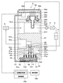
次に、膨張弁5の詳細構成について説明する。膨張弁5は、図2に示すように、空調ケーシング7の外側から、空調ケーシングに固定されている。蒸発器6の出口側は、膨張弁5の内部に形成された蒸発後冷媒通路51fを介して、圧縮機2の吸入側に接続されている。
Next, the detailed configuration of the
膨張弁5は、図2、図3に示すように、ボディ51、弁体52、コイルバネ53、自律部54、バルブモジュールY0等を有する。まず、ボディ51は、膨張弁5の外殻および膨張弁5内の冷媒通路等を構成するもので、円筒状あるいは角筒状の金属ブロックに穴開け加工等を施して形成されている。ボディ51には、第1流入口51a、第1流出口51b、第2流入口51d、第2流入口51d、第2流出口51e、弁室51g、絞り通路51h等が形成されている。
As shown in FIGS. 2 and 3, the
冷媒流入口・流出口としては、凝縮器3の出口に接続されて高圧液相冷媒を流入させる第1流入口51a、第1流入口51aから流入した冷媒を蒸発器6入口側へ流出させる第1流出口51bが形成されている。従って、本実施形態では、第1流入口51aから第1流出口51bへ至る冷媒通路によって、高圧冷媒通路51cが形成される。高圧冷媒通路51cは、第1通路に対応する。
As the refrigerant inlet / outlet, the
また、他の冷媒流入口・流出口として、蒸発器6から流出した低圧冷媒を流入させる第2流入口51d、第2流入口51dから流入した冷媒を圧縮機2吸入側へ流出させる第2流出口51eが形成されている。従って、本実施形態では、第2流入口51dから第2流出口51eへ至る冷媒通路によって、蒸発後冷媒通路51fが形成される。
Further, as other refrigerant inlets / outlets, a
弁室51gは、高圧冷媒通路51cに設けられて、その内部に後述する弁体52が収容される空間である。弁室51gは圧力室に対応する。より具体的には、弁室51gは、第1流入口51aに直接連通し、絞り通路51hを介して第1流出口51bに連通している。絞り通路51hは、高圧冷媒通路51cに設けられて、第1流入口51aから弁室51gへ流入した冷媒を、減圧膨張させながら弁室51g側から第1流出口51b側へ導く通路である。絞り通路51hは、弁体52と弁座51jとの間に形成される。
The
弁座51jは、弁室51gの下流端において冷媒流路を狭めるようにボディ51に形成されている。弁体52は、弁座51jに対して変位することによって、絞り通路51hの冷媒通路面積を連続的にまたは3段階以上の複数段階で調整する弁体である。絞り通路51hはら第1流出口51bへ至る冷媒通路は、低圧冷媒通路51kである。低圧冷媒通路51kは、第2通路に対応する。
The
低圧冷媒通路51kには、低圧導入路51qが接続されている。この低圧導入路51qは、ボディ51に形成され、一端が低圧冷媒通路51kに連通し、他端がバルブモジュールY0の第3連通孔YV3に連通する。
A low
また、高圧冷媒通路51cには、高圧導入路51pが接続されている。この高圧導入路51pは、ボディ51に形成され、一端が高圧冷媒通路51cに連通し、他端がバルブモジュールY0の第2連通孔YV2に連通する。
Further, a high
コイルバネ53は、弁室51gに収容され、弁体52に対して絞り通路51hを閉弁させる側に付勢している。具体的には、コイルバネ53は、弁室51gのうち背圧室51mに配置される。背圧室51mは、弁体52を基準として絞り通路51hとは反対側に形成される。背圧室51mには、バルブモジュールY0の第1連通孔YV1に連通する。以下、弁室51gのうち、弁体52を基準として背圧室51mとは反対側の空間を前側室51sという。弁室51gは、弁体52によって、背圧室51mと前側室51sに仕切られる。
The
自律部54は、ケーシング54a、回路基板54b、複合センサ54c、ドライバ回路54dを含む。ケーシング54aは、ボディ51に固定され、回路基板54b、複合センサ54c、ドライバ回路54dが収容された収容空間を囲む樹脂製の部材である。ボディ51のうち、蒸発後冷媒通路51fを囲んでいる壁には、この収容空間に対して開く開口51rが形成されている。回路基板54bは、ケーシング54aに固定され、複合センサ54c、ドライバ回路54d等が実装されている。
The
複合センサ54cは、ケーシング541と、感応部542と、リード部543と、Oリング544を有している。樹脂製のケーシング541は、ケーシング54aに囲まれた収容空間において、ボディ51に一体に固定されている。より具体的には、ケーシング541は、ボディ51に開けられた開口51rに挿通された状態となっている。したがって、ケーシング541は、蒸発後冷媒通路51f内にある部分と、上記収容空間内にある部分とを有する。
The
Oリング544は、ケーシング541とボディ51の間に介在して、蒸発後冷媒通路51fからケーシング54a内部への冷媒の漏出を抑制する。導電性のリード部543は、回路基板54bにプリントされた配線に接続されている。複合センサ54cは、空隙を介して回路基板54bに対向しているので、リード部543の配策が容易である。
The O-
感応部542は、ケーシング541のうち蒸発後冷媒通路51f内にある部分に固定される。感応部542は、蒸発後冷媒通路51fにおける冷媒の圧力に応じた圧力信号と、蒸発後冷媒通路51fにおける冷媒の温度に応じた温度信号とを、出力する。
The
感応部542は、例えば、圧力センサと、当該圧力センサとは別体の温度センサとを備えていてもよい。あるいは、感応部542は、4つのゲージ抵抗と、当該ブリッジ回路が取り付けられた薄肉状のダイヤフラムとを有していてもよい。各ゲージ抵抗は、ダイヤフラムの上に形成された薄膜抵抗として構成されていてもよい。
The
各ゲージ抵抗は、ダイヤフラムの歪みに応じて抵抗値が変化する抵抗素子である。また、各ゲージ抵抗は、温度に応じて抵抗値が変化する素子である。これらゲージ抵抗は、ホイートストンブリッジ回路を構成するように互いに電気的に接続されている。ホイートストンブリッジ回路には、ドライバ回路54dから、回路基板54b、リード部543、不図示の配線を介して、定電流が供給される。これにより、各ゲージ抵抗のピエゾ抵抗効果により、ダイヤフラムの歪みに応じた圧力信号やダイヤフラムの温度に応じた温度信号が、感応部542から出力される。
Each gauge resistance is a resistance element whose resistance value changes according to the distortion of the diaphragm. Further, each gauge resistance is an element whose resistance value changes according to the temperature. These gauge resistors are electrically connected to each other to form a Wheatstone bridge circuit. A constant current is supplied to the Wheatstone bridge circuit from the
具体的には、感応部542は、ダイヤフラムの歪みに応じた複数のゲージ抵抗の抵抗変化をホイートストンブリッジ回路の中点電圧の変化として検出し、当該中点電圧を圧力信号として出力する。一方、感応部542は、感応部542の温度に応じた複数のゲージ抵抗の抵抗変化をホイートストンブリッジ回路のブリッジ電圧として検出し、当該ブリッジ電圧を温度信号として出力する。
Specifically, the
感応部542から出力された圧力信号と温度信号は、不図示の配線およびそれに導通するリード部543を介して感応部542から回路基板54bに伝達される。回路基板54bに伝達された圧力信号と温度信号は、回路基板54bにプリントされたパターンを介してドライバ回路54dに入力される。
The pressure signal and the temperature signal output from the
ドライバ回路54dは、複合センサ54cから回路基板54bを介して入力された圧力信号と温度信号に基づいて、バルブモジュールY0の作動を制御する。ドライバ回路54dは、例えば、マイクロコンピュータによって実現することが可能であり、あるいは、専用の回路構成を有するハードウェアによって実現することも可能である。
The
[バルブモジュールY0の構成]
ここで、バルブモジュールY0の構成について、図3、図4、図5、図6、図7、図8を用いて説明する。図3、図4に示すように、バルブモジュールY0は、マイクロバルブY1、バルブケーシングY2、封止部材Y3、3つのOリングY4、Y5a、Y5b、2本の電気配線Y6、Y7、変換プレートY8を有している。
[Valve module Y0 configuration]
Here, the configuration of the valve module Y0 will be described with reference to FIGS. 3, 4, 5, 6, 6, 7, and 8. As shown in FIGS. 3 and 4, the valve module Y0 includes a micro valve Y1, a valve casing Y2, a sealing member Y3, three O-rings Y4, Y5a, Y5b, two electrical wirings Y6, Y7, and a conversion plate Y8. have.
マイクロバルブY1は、板形状の制御弁部品であり、主として半導体チップによって構成されている。マイクロバルブY1は、半導体チップ以外の部品を有していてもいなくてもよい。したがって、マイクロバルブY1を小型に構成できる。マイクロバルブY1の厚さ方向の長さは例えば2mmであり、厚さ方向に直交する長手方向の長さは例えば10mmであり、長手方向にも厚さ方向にも直交する短手方向の長さは例えば5mmであるが、これに限定されない。マイクロバルブY1への供給電力が変動することで、マイクロバルブY1の流路構成が変化する。マイクロバルブY1は、パイロット弁として機能する。 The microvalve Y1 is a plate-shaped control valve component, and is mainly composed of a semiconductor chip. The microvalve Y1 may or may not have a component other than the semiconductor chip. Therefore, the micro valve Y1 can be configured in a small size. The length of the microvalve Y1 in the thickness direction is, for example, 2 mm, the length in the longitudinal direction orthogonal to the thickness direction is, for example, 10 mm, and the length in the lateral direction orthogonal to both the longitudinal direction and the thickness direction. Is, for example, 5 mm, but is not limited thereto. As the power supplied to the micro valve Y1 fluctuates, the flow path configuration of the micro valve Y1 changes. The micro valve Y1 functions as a pilot valve.
電気配線Y6、Y7は、マイクロバルブY1の表裏にある2つの板面のうち、バルブケーシングY2とは反対側の面から伸びて、封止部材Y3、バルブケーシングY2内を通過して、バルブモジュールY0の外部にある電源(すなわちドライバ回路54d)に接続される。電気配線Y6、Y7のマイクロバルブY1側とは反対側の端部は、ドライバ回路54dに接続される。これにより、電気配線Y6、Y7を通して、ドライバ回路54dからマイクロバルブY1に電力が供給可能となる。
The electrical wirings Y6 and Y7 extend from the surface of the two plates on the front and back of the microvalve Y1 opposite to the valve casing Y2, pass through the sealing member Y3 and the valve casing Y2, and pass through the valve module. It is connected to a power supply (that is, a
変換プレートY8は、マイクロバルブY1とバルブケーシングY2の間に配置される板形状の部材である。変換プレートY8は、ガラス基板である。変換プレートY8の表裏にある2つの板面の一方側は、マイクロバルブY1に対して接着剤で固定され、他方側はバルブケーシングY2に対して接着剤で固定されている。変換プレートY8には、マイクロバルブY1の後述する3つの冷媒孔Y16、Y17、Y18とバルブケーシングY2の3つの連通孔YV1、YV2、YV3とを繋げるための流路Y81、Y82、Y83が形成されている。これら流路Y81、Y82、Y83は、一列に並ぶ上記3つの冷媒孔Y16、Y17、Y18間のピッチと、一列に並ぶ上記3つの連通孔YV1、YV2、YV3間のピッチとの違いを、吸収するための流路である。連通孔YV1、YV2、YV3間のピッチは冷媒孔Y16、Y17、Y18間のピッチよりも大きい。流路Y81、Y82、Y83は、変換プレートY8の表裏にある2つの板面の一方から他方に貫通している。したがって、流路Y81、Y82、Y83の連通孔YV1、YV2、YV3側の端部の間のピッチは、流路Y81、Y82、Y83の上記冷媒孔Y16、Y17、Y18側の端部の間のピッチよりも、大きい。 The conversion plate Y8 is a plate-shaped member arranged between the microvalve Y1 and the valve casing Y2. The conversion plate Y8 is a glass substrate. One side of the two plate surfaces on the front and back surfaces of the conversion plate Y8 is fixed to the microvalve Y1 with an adhesive, and the other side is fixed to the valve casing Y2 with an adhesive. The conversion plate Y8 is formed with flow paths Y81, Y82, Y83 for connecting the three refrigerant holes Y16, Y17, Y18 described later of the micro valve Y1 and the three communication holes YV1, YV2, YV3 of the valve casing Y2. ing. These flow paths Y81, Y82, and Y83 absorb the difference between the pitch between the three refrigerant holes Y16, Y17, and Y18 arranged in a row and the pitch between the three communication holes YV1, YV2, and YV3 arranged in a row. It is a flow path for doing. The pitch between the communication holes YV1, YV2, and YV3 is larger than the pitch between the refrigerant holes Y16, Y17, and Y18. The flow paths Y81, Y82, and Y83 penetrate from one of the two plate surfaces on the front and back of the conversion plate Y8 to the other. Therefore, the pitch between the ends of the flow paths Y81, Y82, and Y83 on the side of the communication holes YV1, YV2, and YV3 is set between the ends of the flow paths Y81, Y82, and Y83 on the side of the refrigerant holes Y16, Y17, and Y18. Greater than the pitch.
バルブケーシングY2は、マイクロバルブY1および変換プレートY8を収容する樹脂製のケーシングである。バルブケーシングY2は、ポリフェニレンサルファイドを主成分として樹脂成型によって形成されている。バルブケーシングY2は、一方側に底壁を有し、他方側が開放された箱体である。バルブケーシングY2の底壁は、マイクロバルブY1および変換プレートY8がボディ51に直接接しないように、ボディ51とマイクロバルブY1の間に介在する。そして、この底壁の一方側の面がボディ51に接触して固定され、他方側の面が変換プレートY8に接触して固定される。
The valve casing Y2 is a resin casing that houses the microvalve Y1 and the conversion plate Y8. The valve casing Y2 is formed by resin molding containing polyphenylene sulfide as a main component. The valve casing Y2 is a box body having a bottom wall on one side and an open side on the other side. The bottom wall of the valve casing Y2 is interposed between the
このようになっていることで、マイクロバルブY1とボディ51の線膨張係数の違いをバルブケーシングY2が吸収できる。これは、バルブケーシングY2の線膨張係数が、マイクロバルブY1の線膨張係数とボディ51の線膨張係数の間の値となっているからである。なお、変換プレートY8の線膨張係数は、マイクロバルブY1の線膨張係数とバルブケーシングY2の線膨張係数の間の値となっている。
In this way, the valve casing Y2 can absorb the difference in the linear expansion coefficient between the micro valve Y1 and the
また、バルブケーシングY2の底壁は、マイクロバルブY1に対向する板形状のベース部Y20と、マイクロバルブY1から離れる方向に当該ベース部Y20から突出する柱形状の第1突出部Y21、第2突出部Y22、第3突出部Y23を有する。 Further, the bottom wall of the valve casing Y2 has a plate-shaped base portion Y20 facing the microvalve Y1 and a pillar-shaped first protruding portion Y21 and a second protruding portion Y21 protruding from the base portion Y20 in a direction away from the microvalve Y1. It has a portion Y22 and a third protruding portion Y23.
第1突出部Y21、第2突出部Y22、第3突出部Y23は、ボディ51に形成された凹みに嵌め込まれている。第1突出部Y21には、マイクロバルブY1側端からその反対側端まで貫通する第1連通孔YV1が形成されている。第2突出部Y22には、マイクロバルブY1側端からその反対側端まで貫通する第2連通孔YV2が形成されている。第3突出部Y23には、マイクロバルブY1側端からその反対側端まで貫通する第3連通孔YV3が形成されている。第1連通孔YV1、第2連通孔YV2、第3連通孔YV3は一列に並んでおり、第2連通孔YV2と第3連通孔YV3の間に第1連通孔YV1が位置する。
The first protruding portion Y21, the second protruding portion Y22, and the third protruding portion Y23 are fitted into the recess formed in the
第1連通孔YV1のマイクロバルブY1側端は、変換プレートY8に形成された流路Y81のバルブケーシングY2側端に連通している。第2連通孔YV2のマイクロバルブY1側端は、変換プレートY8に形成された流路Y82のバルブケーシングY2側端に連通している。第3連通孔YV3のマイクロバルブY1側端は、変換プレートY8に形成された流路Y83のバルブケーシングY2側端に連通している。 The microvalve Y1 side end of the first communication hole YV1 communicates with the valve casing Y2 side end of the flow path Y81 formed in the conversion plate Y8. The microvalve Y1 side end of the second communication hole YV2 communicates with the valve casing Y2 side end of the flow path Y82 formed in the conversion plate Y8. The microvalve Y1 side end of the third communication hole YV3 communicates with the valve casing Y2 side end of the flow path Y83 formed in the conversion plate Y8.
封止部材Y3は、バルブケーシングY2の開放された上記他方側を封止するエポキシ樹脂製の部材である。封止部材Y3は、マイクロバルブY1の表裏にある2つの板面のうち、変換プレートY8側とは反対側の板面の全体を覆う。また、封止部材Y3は、変換プレートY8の表裏にある2つの板面のうち、バルブケーシングY2の底壁側とは反対側の板面の一部を覆う。また、封止部材Y3は、電気配線Y6、Y7を覆うことで、電気配線Y6、Y7の防水および絶縁を実現する。封止部材Y3は樹脂ポッティング等によって形成される。 The sealing member Y3 is a member made of epoxy resin that seals the other open side of the valve casing Y2. The sealing member Y3 covers the entire plate surface on the side opposite to the conversion plate Y8 side among the two plate surfaces on the front and back of the micro valve Y1. Further, the sealing member Y3 covers a part of the plate surface on the opposite side of the valve casing Y2 from the bottom wall side of the two plate surfaces on the front and back of the conversion plate Y8. Further, the sealing member Y3 covers the electric wirings Y6 and Y7 to realize waterproofing and insulation of the electric wirings Y6 and Y7. The sealing member Y3 is formed by resin potting or the like.
OリングY4は、第1突出部Y21の外周に取り付けられ、ボディ51と第1突出部Y21の間を封止することで、膨張弁5の外部かつ冷凍サイクルの外部への冷媒の漏出を抑制する。OリングY5aは、第2突出部Y22の外周に取り付けられ、ボディ51と第2突出部Y22の間を封止することで、膨張弁5の外部かつ冷凍サイクルの外部への冷媒の漏出を抑制する。OリングY5bは、第3突出部Y23の外周に取り付けられ、ボディ51と第3突出部Y23の間を封止することで、膨張弁5の外部かつ冷凍サイクルの外部への冷媒の漏出を抑制する。
The O-ring Y4 is attached to the outer periphery of the first protruding portion Y21, and by sealing between the
ここで、マイクロバルブY1の構成について更に説明する。マイクロバルブY1は、図5、図6に示すように、いずれも半導体である第1外層Y11、中間層Y12、第2外層Y13を備えたMEMSである。MEMSは、Micro Electro Mechanical Systemsの略称である。第1外層Y11、中間層Y12、第2外層Y13は、それぞれが同じ外形を有する長方形の板形状の部材であり、第1外層Y11、中間層Y12、第2外層Y13の順に積層されている。すなわち、中間層Y12が、第1外層Y11と第2外層Y13に両側から挟まれている。第1外層Y11、中間層Y12、第2外層Y13のうち、第2外層Y13が、バルブケーシングY2の底壁に最も近い側に配置される。後述する第1外層Y11、中間層Y12、第2外層Y13の構造は、化学的エッチング等の半導体製造プロセスによって形成される。 Here, the configuration of the microvalve Y1 will be further described. As shown in FIGS. 5 and 6, the microvalve Y1 is a MEMS having a first outer layer Y11, an intermediate layer Y12, and a second outer layer Y13, all of which are semiconductors. MEMS is an abbreviation for Micro Electro Mechanical Systems. The first outer layer Y11, the intermediate layer Y12, and the second outer layer Y13 are rectangular plate-shaped members having the same outer shape, and the first outer layer Y11, the intermediate layer Y12, and the second outer layer Y13 are laminated in this order. That is, the intermediate layer Y12 is sandwiched between the first outer layer Y11 and the second outer layer Y13 from both sides. Of the first outer layer Y11, the intermediate layer Y12, and the second outer layer Y13, the second outer layer Y13 is arranged on the side closest to the bottom wall of the valve casing Y2. The structures of the first outer layer Y11, the intermediate layer Y12, and the second outer layer Y13, which will be described later, are formed by a semiconductor manufacturing process such as chemical etching.
第1外層Y11は、表面に非導電性の酸化膜のある導電性の半導体部材である。第1外層Y11には、図5に示すように、表裏に貫通する2つの貫通孔Y14、Y15が形成されている。この貫通孔Y14、Y15に、それぞれ、電気配線Y6、Y7のマイクロバルブY1側端が挿入される。 The first outer layer Y11 is a conductive semiconductor member having a non-conductive oxide film on its surface. As shown in FIG. 5, two through holes Y14 and Y15 penetrating the front and back are formed in the first outer layer Y11. The microvalve Y1 side ends of the electrical wirings Y6 and Y7 are inserted into the through holes Y14 and Y15, respectively.
第2外層Y13は、表面に非導電性の酸化膜のある導電性の半導体部材である。第2外層Y13には、図5、図7、図8に示すように、表裏に貫通する第1冷媒孔Y16、第2冷媒孔Y17、第3冷媒孔Y18が形成されている。 The second outer layer Y13 is a conductive semiconductor member having a non-conductive oxide film on its surface. As shown in FIGS. 5, 7, and 8, the second outer layer Y13 is formed with a first refrigerant hole Y16, a second refrigerant hole Y17, and a third refrigerant hole Y18 penetrating the front and back surfaces.
図8に示すように、第1冷媒孔Y16、第2冷媒孔Y17、第3冷媒孔Y18は、それぞれ、変換プレートY8の流路Y81、Y82、Y83に連通する。第1冷媒孔Y16、第2冷媒孔Y17、第3冷媒孔Y18は、一列に並んでいる。第2冷媒孔Y17と第3冷媒孔Y18の間に第1冷媒孔Y16が配置される。第1冷媒孔Y16、第2冷媒孔Y17、第3冷媒孔Y18の各々の水力直径は、例えば0.1mm以上かつ3mm以下であるが、これに限定されない。 As shown in FIG. 8, the first refrigerant hole Y16, the second refrigerant hole Y17, and the third refrigerant hole Y18 communicate with the flow paths Y81, Y82, and Y83 of the conversion plate Y8, respectively. The first refrigerant hole Y16, the second refrigerant hole Y17, and the third refrigerant hole Y18 are arranged in a row. The first refrigerant hole Y16 is arranged between the second refrigerant hole Y17 and the third refrigerant hole Y18. The hydraulic diameters of the first refrigerant holes Y16, the second refrigerant holes Y17, and the third refrigerant holes Y18 are, for example, 0.1 mm or more and 3 mm or less, but are not limited thereto.
中間層Y12は、導電性の半導体部材であり、第1外層Y11と第2外層Y13に挟まれている。中間層Y12は、第1外層Y11の酸化膜と第2外層Y13の酸化膜に接触するので、第1外層Y11と第2外層Y13とも電気的に非導通である。中間層Y12は、図7に示すように、第1固定部Y121、第2固定部Y122、複数本の第1リブY123、複数本の第2リブY124、スパインY125、アームY126、梁Y127、可動部Y128を有している。 The intermediate layer Y12 is a conductive semiconductor member, and is sandwiched between the first outer layer Y11 and the second outer layer Y13. Since the intermediate layer Y12 comes into contact with the oxide film of the first outer layer Y11 and the oxide film of the second outer layer Y13, both the first outer layer Y11 and the second outer layer Y13 are electrically non-conducting. As shown in FIG. 7, the intermediate layer Y12 has a first fixed portion Y121, a second fixed portion Y122, a plurality of first ribs Y123, a plurality of second ribs Y124, a spine Y125, an arm Y126, a beam Y127, and a movable beam. It has a part Y128.
第1固定部Y121は、第1外層Y11、第2外層Y13に対して固定された部材である。第1固定部Y121は、第2固定部Y122、第1リブY123、第2リブY124、スパインY125、アームY126、梁Y127、可動部Y128を同じ1つの冷媒室Y19内に囲むように形成されている。冷媒室Y19は、第1固定部Y121、第1外層Y11、第2外層Y13によって囲まれた室である。第1固定部Y121、第1外層Y11、第2外層Y13は、全体として基部に対応する。なお、電気配線Y6、Y7は複数の第1リブY123および複数の第2リブY124の温度を変化させて変位させるための電気配線である。 The first fixing portion Y121 is a member fixed to the first outer layer Y11 and the second outer layer Y13. The first fixed portion Y121 is formed so as to surround the second fixed portion Y122, the first rib Y123, the second rib Y124, the spine Y125, the arm Y126, the beam Y127, and the movable portion Y128 in the same one refrigerant chamber Y19. There is. The refrigerant chamber Y19 is a chamber surrounded by a first fixing portion Y121, a first outer layer Y11, and a second outer layer Y13. The first fixed portion Y121, the first outer layer Y11, and the second outer layer Y13 correspond to the base portion as a whole. The electrical wirings Y6 and Y7 are electrical wirings for changing the temperature of the plurality of first ribs Y123 and the plurality of second ribs Y124 to displace them.
第1固定部Y121の第1外層Y11および第2外層Y13に対する固定は、冷媒がこの冷媒室Y19から第1冷媒孔Y16、第2冷媒孔Y17、第3冷媒孔Y18以外を通ってマイクロバルブY1から漏出することを抑制するような形態で、行われている。 In the fixing of the first fixing portion Y121 to the first outer layer Y11 and the second outer layer Y13, the refrigerant passes from the refrigerant chamber Y19 through other than the first refrigerant hole Y16, the second refrigerant hole Y17, and the third refrigerant hole Y18, and the microvalve Y1. It is performed in a form that suppresses leakage from the refrigerant.
第2固定部Y122は、第1外層Y11、第2外層Y13に対して固定される。第2固定部Y122は、第1固定部Y121に取り囲まれると共に、第1固定部Y121から離れて配置される。 The second fixing portion Y122 is fixed to the first outer layer Y11 and the second outer layer Y13. The second fixed portion Y122 is surrounded by the first fixed portion Y121 and is arranged away from the first fixed portion Y121.
複数本の第1リブY123、複数本の第2リブY124、スパインY125、アームY126、梁Y127、可動部Y128は、第1外層Y11、第2外層Y13に対して固定されておらず、第1外層Y11、第2外層Y13に対して変位可能である。 The plurality of first ribs Y123, the plurality of second ribs Y124, the spine Y125, the arm Y126, the beam Y127, and the movable portion Y128 are not fixed to the first outer layer Y11 and the second outer layer Y13, and are the first. It is displaceable with respect to the outer layer Y11 and the second outer layer Y13.
スパインY125は、中間層Y12の矩形形状の短手方向に伸びる細長い棒形状を有している。スパインY125の長手方向の一端は、梁Y127に接続されている。 The spine Y125 has an elongated rod shape extending in the lateral direction of the rectangular shape of the intermediate layer Y12. One end of the spine Y125 in the longitudinal direction is connected to the beam Y127.
複数本の第1リブY123は、スパインY125の長手方向に直交する方向におけるスパインY125の一方側に配置される。そして、複数本の第1リブY123は、スパインY125の長手方向に並んでいる。各第1リブY123は、細長い棒形状を有しており、温度に応じて伸縮可能となっている。 The plurality of first ribs Y123 are arranged on one side of the spine Y125 in a direction orthogonal to the longitudinal direction of the spine Y125. The plurality of first ribs Y123 are arranged in the longitudinal direction of the spine Y125. Each first rib Y123 has an elongated rod shape and can be expanded and contracted according to the temperature.
各第1リブY123は、その長手方向の一端で第1固定部Y121に接続され、他端でスパインY125に接続される。そして、各第1リブY123は、第1固定部Y121側からスパインY125側に近付くほど、スパインY125の長手方向の梁Y127側に向けてオフセットされるよう、スパインY125に対して斜行している。そして、複数の第1リブY123は、互いに対して平行に伸びている。 Each first rib Y123 is connected to the first fixing portion Y121 at one end in the longitudinal direction thereof and to the spine Y125 at the other end. Each of the first ribs Y123 is skewed with respect to the spine Y125 so as to approach the spine Y125 side from the first fixing portion Y121 side so as to be offset toward the beam Y127 side in the longitudinal direction of the spine Y125. .. The plurality of first ribs Y123 extend in parallel with each other.
複数本の第2リブY124は、スパインY125の長手方向に直交する方向におけるスパインY125の他方側に配置される。そして、複数本の第2リブY124は、スパインY125の長手方向に並んでいる。各第2リブY124は、細長い棒形状を有しており、温度に応じて伸縮可能となっている。 The plurality of second ribs Y124 are arranged on the other side of the spine Y125 in a direction orthogonal to the longitudinal direction of the spine Y125. The plurality of second ribs Y124 are arranged in the longitudinal direction of the spine Y125. Each second rib Y124 has an elongated rod shape and can be expanded and contracted according to the temperature.
各第2リブY124は、その長手方向の一端で第2固定部Y122に接続され、他端でスパインY125に接続される。そして、各第2リブY124は、第2固定部Y122側からスパインY125側に近付くほど、スパインY125の長手方向の梁Y127側に向けてオフセットされるよう、スパインY125に対して斜行している。そして、複数の第2リブY124は、互いに対して平行に伸びている。 Each second rib Y124 is connected to the second fixing portion Y122 at one end in the longitudinal direction thereof and to the spine Y125 at the other end. Each of the second ribs Y124 is skewed with respect to the spine Y125 so as to approach the spine Y125 side from the second fixed portion Y122 side so as to be offset toward the beam Y127 side in the longitudinal direction of the spine Y125. .. The plurality of second ribs Y124 extend in parallel with each other.
複数本の第1リブY123、複数本の第2リブY124、スパインY125は、全体として、駆動部に対応する。 The plurality of first ribs Y123, the plurality of second ribs Y124, and the spine Y125 correspond to the drive unit as a whole.
アームY126は、スパインY125と非直交かつ平行に伸びる細長い棒形状を有している。アームY126の長手方向の一端は梁Y127に接続されており、他端は第1固定部Y121に接続されている。 The arm Y126 has an elongated rod shape extending non-orthogonally and parallel to the spine Y125. One end of the arm Y126 in the longitudinal direction is connected to the beam Y127, and the other end is connected to the first fixing portion Y121.
梁Y127は、スパインY125およびアームY126に対して約90°で交差する方向に伸びる細長い棒形状を有している。梁Y127の一端は、可動部Y128に接続されている。アームY126と梁Y127は、全体として、増幅部に対応する。 The beam Y127 has an elongated rod shape extending in a direction intersecting the spine Y125 and the arm Y126 at about 90 °. One end of the beam Y127 is connected to the movable portion Y128. The arm Y126 and the beam Y127 correspond to the amplification portion as a whole.
アームY126と梁Y127の接続位置YP1、スパインY125と梁Y127の接続位置YP2、梁Y127と可動部Y128の接続位置YP3は、梁Y127の長手方向に沿って、この順に並んでいる。そして、第1固定部Y121とアームY126との接続点をヒンジYP0とすると、中間層Y12の板面に平行な面内におけるヒンジYP0から接続位置YP2までの直線距離よりも、ヒンジYP0から接続位置YP3までの直線距離の方が、長い。例えば、前者の直線距離を後者の直線距離で除算した値は、1/5以下であってもよいし、1/10以下であってもよい。 The connection position YP1 between the arm Y126 and the beam Y127, the connection position YP2 between the spine Y125 and the beam Y127, and the connection position YP3 between the beam Y127 and the movable portion Y128 are arranged in this order along the longitudinal direction of the beam Y127. If the connection point between the first fixing portion Y121 and the arm Y126 is a hinge YP0, the connection position from the hinge YP0 is more than the linear distance from the hinge YP0 to the connection position YP2 in the plane parallel to the plate surface of the intermediate layer Y12. The straight line distance to YP3 is longer. For example, the value obtained by dividing the former straight line distance by the latter straight line distance may be 1/5 or less, or may be 1/10 or less.
可動部Y128は、その外形が、梁Y127の長手方向に対して概ね90°の方向に伸びる矩形形状を有している。この可動部Y128は、冷媒室Y19内において梁Y127と一体に動くことができる。そして、可動部Y128は、中間層Y12の表裏に貫通する貫通孔Y120を囲む枠形状となっている。したがって、貫通孔Y120も、可動部Y128と一体的に移動する。貫通孔Y120は、冷媒室Y19の一部である。 The movable portion Y128 has a rectangular shape whose outer shape extends in a direction of approximately 90 ° with respect to the longitudinal direction of the beam Y127. The movable portion Y128 can move integrally with the beam Y127 in the refrigerant chamber Y19. The movable portion Y128 has a frame shape surrounding the through hole Y120 penetrating the front and back of the intermediate layer Y12. Therefore, the through hole Y120 also moves integrally with the movable portion Y128. The through hole Y120 is a part of the refrigerant chamber Y19.
可動部Y128は、上記のように動くことで、第2冷媒孔Y17の貫通孔Y120に対する開度および、第3冷媒孔Y18の貫通孔Y120に対する開度を変更する。第1冷媒孔Y16は、貫通孔Y120に対して常に全開で連通している。 By moving as described above, the movable portion Y128 changes the opening degree of the second refrigerant hole Y17 with respect to the through hole Y120 and the opening degree of the third refrigerant hole Y18 with respect to the through hole Y120. The first refrigerant hole Y16 always communicates with the through hole Y120 in full opening.
また、第1固定部Y121のうち、複数の第1リブY123と接続する部分の近傍の第1印加点Y129には、図5に示した第1外層Y11の貫通孔Y14を通った電気配線Y6のマイクロバルブY1側端が接続される。また、第2固定部Y122の第2印加点Y130には、図5に示した第1外層Y11の貫通孔Y15を通った電気配線Y7のマイクロバルブY1側端が接続される。 Further, at the first application point Y129 in the vicinity of the portion of the first fixed portion Y121 connected to the plurality of first ribs Y123, the electric wiring Y6 passing through the through hole Y14 of the first outer layer Y11 shown in FIG. The Y1 side end of the micro valve is connected. Further, the microvalve Y1 side end of the electric wiring Y7 passing through the through hole Y15 of the first outer layer Y11 shown in FIG. 5 is connected to the second application point Y130 of the second fixing portion Y122.
[バルブモジュールY0の作動]
ここで、バルブモジュールY0の作動について説明する。マイクロバルブY1への通電が開始されると、電気配線Y6、Y7から第1印加点Y129、第2印加点Y130の間に電圧が印加される。すると、複数の第1リブY123、複数の第2リブY124を電流が流れる。この電流によって、複数の第1リブY123、複数の第2リブY124が発熱する。その結果、複数の第1リブY123、複数の第2リブY124の各々が、その長手方向に膨張する。
[Operation of valve module Y0]
Here, the operation of the valve module Y0 will be described. When the energization of the microvalve Y1 is started, a voltage is applied between the electrical wirings Y6 and Y7 to the first application point Y129 and the second application point Y130. Then, a current flows through the plurality of first ribs Y123 and the plurality of second ribs Y124. Due to this current, the plurality of first ribs Y123 and the plurality of second ribs Y124 generate heat. As a result, each of the plurality of first ribs Y123 and the plurality of second ribs Y124 expands in the longitudinal direction thereof.
このような熱的な膨張の結果、複数の第1リブY123、複数の第2リブY124は、スパインY125を接続位置YP2側に付勢する。付勢されたスパインY125は、接続位置YP2において、梁Y127を押す。このように、接続位置YP2は付勢位置に対応する。その結果、梁Y127とアームY126から成る部材は、ヒンジYP0を支点として、接続位置YP2を力点として、一体に姿勢を変える。その結果、梁Y127のアームY126とは反対側の端部に接続された可動部Y128も、その長手方向の、スパインY125が梁Y127を押す側に、移動する。 As a result of such thermal expansion, the plurality of first ribs Y123 and the plurality of second ribs Y124 urge the spine Y125 toward the connection position YP2. The urged spine Y125 pushes the beam Y127 at the connection position YP2. In this way, the connection position YP2 corresponds to the urging position. As a result, the member including the beam Y127 and the arm Y126 changes their postures integrally with the hinge YP0 as the fulcrum and the connection position YP2 as the power point. As a result, the movable portion Y128 connected to the end of the beam Y127 opposite to the arm Y126 also moves in the longitudinal direction to the side where the spine Y125 pushes the beam Y127.
また、マイクロバルブY1への通電が停止されたときは、電気配線Y6、Y7から第1印加点Y129、第2印加点Y130への電圧印加が停止される。すると、複数の第1リブY123、複数の第2リブY124を電流が流れなくなり、複数の第1リブY123、複数の第2リブY124の温度が低下する。その結果、複数の第1リブY123、複数の第2リブY124の各々が、その長手方向に収縮する。 When the energization of the microvalve Y1 is stopped, the voltage application from the electrical wirings Y6 and Y7 to the first application point Y129 and the second application point Y130 is stopped. Then, the current does not flow through the plurality of first ribs Y123 and the plurality of second ribs Y124, and the temperatures of the plurality of first ribs Y123 and the plurality of second ribs Y124 decrease. As a result, each of the plurality of first ribs Y123 and the plurality of second ribs Y124 contracts in the longitudinal direction thereof.
このような熱的な収縮の結果、複数の第1リブY123、複数の第2リブY124は、スパインY125を接続位置YP2とは反対側に付勢する。付勢されたスパインY125は、接続位置YP2において、梁Y127を引っ張る。その結果、梁Y127とアームY126から成る部材は、ヒンジYP0を支点として、接続位置YP2を力点として、一体に姿勢を変える。その結果、梁Y127のアームY126とは反対側の端部に接続された可動部Y128も、その長手方向の、スパインY125が梁Y127を引っ張る側に、移動する。その移動の結果、可動部Y128は、所定の非通電時位置で停止する。非通電時位置は、第1位置に対応する。 As a result of such thermal contraction, the plurality of first ribs Y123 and the plurality of second ribs Y124 urge the spine Y125 to the side opposite to the connection position YP2. The urged spine Y125 pulls the beam Y127 at the connection position YP2. As a result, the member including the beam Y127 and the arm Y126 changes their postures integrally with the hinge YP0 as the fulcrum and the connection position YP2 as the power point. As a result, the movable portion Y128 connected to the end of the beam Y127 opposite to the arm Y126 also moves in the longitudinal direction to the side where the spine Y125 pulls the beam Y127. As a result of the movement, the movable portion Y128 stops at a predetermined non-energized position. The non-energized position corresponds to the first position.
このようなマイクロバルブY1への通電時、電気配線Y6、Y7から第1印加点Y129、第2印加点Y130を介してマイクロバルブY1に供給される電力が大きいほど、非通電時位置に対する可動部Y128の移動量も大きくなる。これは、マイクロバルブY1に供給される電力が高いほど、第1リブY123、第2リブY124の温度が高くなり、膨張度合いが大きいからである。 When the microvalve Y1 is energized, the larger the power supplied from the electrical wirings Y6 and Y7 to the microvalve Y1 via the first application point Y129 and the second application point Y130, the more the movable portion with respect to the non-energized position. The amount of movement of Y128 also increases. This is because the higher the electric power supplied to the micro valve Y1, the higher the temperature of the first rib Y123 and the second rib Y124, and the larger the degree of expansion.
例えば電気配線Y6、Y7から第1印加点Y129、第2印加点Y130へ印加される電圧がPWM制御される場合、電圧のデューティ比が大きいほど非通電時に対する可動部Y128の移動量も大きくなる。以下、PWM制御における電圧のデューティ比を、単にデューティ比という。 For example, when the voltage applied from the electrical wirings Y6 and Y7 to the first application point Y129 and the second application point Y130 is PWM controlled, the larger the duty ratio of the voltage, the larger the amount of movement of the movable portion Y128 with respect to the non-energized state. .. Hereinafter, the duty ratio of the voltage in PWM control is simply referred to as a duty ratio.
図7、図8に示すように、可動部Y128が非通電時位置にある場合、貫通孔Y120は、中間層Y12の板面に直交する方向に第1冷媒孔Y16、第3冷媒孔Y18と重なるが、当該方向に第2冷媒孔Y17とは重ならない。第2冷媒孔Y17は、中間層Y12の板面に直交する方向に可動部Y128と重なる。つまりこのとき、貫通孔Y120に対して第1冷媒孔Y16、第3冷媒孔Y18は全開になり、第2冷媒孔Y17は全閉になる。したがってこの場合、第1冷媒孔Y16が第3冷媒孔Y18に可動部Y128を介して連通し、第2冷媒孔Y17は第1冷媒孔Y16とも第3冷媒孔Y18とも遮断される。この結果、第1連通孔YV1と第3連通孔YV3との間で、流路Y81、第1冷媒孔Y16、貫通孔Y120、第3冷媒孔Y18、流路Y83を介した、冷媒の流通が可能となる。 As shown in FIGS. 7 and 8, when the movable portion Y128 is in the non-energized position, the through hole Y120 has the first refrigerant hole Y16 and the third refrigerant hole Y18 in the direction orthogonal to the plate surface of the intermediate layer Y12. Although it overlaps, it does not overlap with the second refrigerant hole Y17 in the relevant direction. The second refrigerant hole Y17 overlaps the movable portion Y128 in the direction orthogonal to the plate surface of the intermediate layer Y12. That is, at this time, the first refrigerant hole Y16 and the third refrigerant hole Y18 are fully opened with respect to the through hole Y120, and the second refrigerant hole Y17 is fully closed. Therefore, in this case, the first refrigerant hole Y16 communicates with the third refrigerant hole Y18 via the movable portion Y128, and the second refrigerant hole Y17 is blocked from both the first refrigerant hole Y16 and the third refrigerant hole Y18. As a result, the flow of the refrigerant between the first communication hole YV1 and the third communication hole YV3 via the flow path Y81, the first refrigerant hole Y16, the through hole Y120, the third refrigerant hole Y18, and the flow path Y83. It will be possible.
また、図9、図10に示すように、マイクロバルブY1への通電によって可動部Y128が非通電時位置から最も遠ざかった位置にある場合、そのときの可動部Y128の位置を最大通電時位置という。最大通電時位置は第2位置に対応する。可動部Y128が最大通電時位置にある場合は、マイクロバルブY1へ供給される電力が制御範囲内の最大となる。例えば、可動部Y128が最大通電時位置にある場合、上述のPWM制御においてデューティ比が制御範囲内の最大値(例えば100%)となる。 Further, as shown in FIGS. 9 and 10, when the movable portion Y128 is located at the position farthest from the non-energized position due to the energization of the micro valve Y1, the position of the movable portion Y128 at that time is referred to as the maximum energized position. .. The maximum energized position corresponds to the second position. When the movable portion Y128 is in the maximum energized position, the electric power supplied to the microvalve Y1 becomes the maximum within the control range. For example, when the movable portion Y128 is in the maximum energized position, the duty ratio becomes the maximum value (for example, 100%) within the control range in the above-mentioned PWM control.
可動部Y128が最大通電時位置にある場合、貫通孔Y120は、中間層Y12の板面に直交する方向に第1冷媒孔Y16、第2冷媒孔Y17と重なるが、当該方向に第3冷媒孔Y18とは重ならない。第3冷媒孔Y18は、中間層Y12の板面に直交する方向に可動部Y128と重なる。つまりこのとき、貫通孔Y120に対して第1冷媒孔Y16、第2冷媒孔Y17は全開になり、第3冷媒孔Y18は全閉になる。したがってこの場合、第1冷媒孔Y16が第2冷媒孔Y17に可動部Y128を介して連通し、第3冷媒孔Y18は第1冷媒孔Y16とも第2冷媒孔Y17とも遮断される。この結果、第1連通孔YV1と第2連通孔YV2との間で、流路Y81、第1冷媒孔Y16、貫通孔Y120、第2冷媒孔Y17、流路Y83を介した、冷媒の流通が可能となる。 When the movable portion Y128 is in the maximum energized position, the through hole Y120 overlaps with the first refrigerant hole Y16 and the second refrigerant hole Y17 in the direction orthogonal to the plate surface of the intermediate layer Y12, but the third refrigerant hole Y17 is in that direction. It does not overlap with Y18. The third refrigerant hole Y18 overlaps the movable portion Y128 in the direction orthogonal to the plate surface of the intermediate layer Y12. That is, at this time, the first refrigerant hole Y16 and the second refrigerant hole Y17 are fully opened with respect to the through hole Y120, and the third refrigerant hole Y18 is fully closed. Therefore, in this case, the first refrigerant hole Y16 communicates with the second refrigerant hole Y17 via the movable portion Y128, and the third refrigerant hole Y18 is blocked from both the first refrigerant hole Y16 and the second refrigerant hole Y17. As a result, the flow of the refrigerant between the first communication hole YV1 and the second communication hole YV2 via the flow path Y81, the first refrigerant hole Y16, the through hole Y120, the second refrigerant hole Y17, and the flow path Y83. It will be possible.
また、マイクロバルブY1に供給される電力が(例えばPWM制御で)、最大電力未満かつゼロより大きい範囲内で、複数段階でまたは連続的に、調整される。これにより、可動部Y128を、非通電時位置と最大通電時位置の間のどの中間位置にでも、停止させることができる。例えば、最大通電時位置と非通電時位置からも等距離の位置(すなわち、中央位置)で可動部Y128を停止させるには、マイクロバルブY1に供給される電力が、制御範囲内の最大値の半分であればいい。例えば、PWM制御におけるデューティ比が50%であればいい。 Further, the electric power supplied to the microvalve Y1 (for example, by PWM control) is adjusted in a plurality of steps or continuously within a range of less than the maximum electric power and greater than zero. As a result, the movable portion Y128 can be stopped at any intermediate position between the non-energized position and the maximum energized position. For example, in order to stop the movable portion Y128 at a position equidistant from the maximum energized position and the non-energized position (that is, the central position), the power supplied to the microvalve Y1 is the maximum value within the control range. It should be half. For example, the duty ratio in PWM control may be 50%.
可動部Y128が中間位置に停止している場合、第1冷媒孔Y16、第2冷媒孔Y17、第3冷媒孔Y18は、いずれも貫通孔Y120に連通している。しかし、第2冷媒孔Y17および第3冷媒孔Y18は、貫通孔Y120に対して全開状態ではなく、100%未満かつ0%よりも大きい中間開度となっている。可動部Y128が中間位置において最大通電位時位置に近づくほど、貫通孔Y120に対する第3冷媒孔Y18の中間開度が減少し、第2冷媒孔Y17の中間開度が増大する。 When the movable portion Y128 is stopped at an intermediate position, the first refrigerant hole Y16, the second refrigerant hole Y17, and the third refrigerant hole Y18 all communicate with the through hole Y120. However, the second refrigerant hole Y17 and the third refrigerant hole Y18 are not fully opened with respect to the through hole Y120, and have an intermediate opening degree of less than 100% and larger than 0%. As the movable portion Y128 approaches the position at the maximum potential at the intermediate position, the intermediate opening degree of the third refrigerant hole Y18 with respect to the through hole Y120 decreases, and the intermediate opening degree of the second refrigerant hole Y17 increases.
本実施形態では、後述する通り、第2冷媒孔Y17に対して高圧が作用し、第3冷媒孔Y18に対して当該高圧よりも高い低圧が作用する。このとき、可動部Y128が中間位置にあれば、第1冷媒孔Y16からマイクロバルブY1の外部に、当該低圧よりも高く当該高圧よりも低い中間圧が作用する。中間圧の値は、可動部Y128に対する第2冷媒孔Y17の開度と第3冷媒孔Y18の開度によって変動する。 In the present embodiment, as will be described later, a high pressure acts on the second refrigerant hole Y17, and a low pressure higher than the high pressure acts on the third refrigerant hole Y18. At this time, if the movable portion Y128 is in the intermediate position, an intermediate pressure higher than the low pressure and lower than the high pressure acts on the outside of the microvalve Y1 from the first refrigerant hole Y16. The value of the intermediate pressure varies depending on the opening degree of the second refrigerant hole Y17 and the opening degree of the third refrigerant hole Y18 with respect to the movable portion Y128.
図11に、電気配線Y6、Y7から第1印加点Y129、第2印加点Y130へ印加される電圧がPWM制御される場合における、デューティ比と、第1冷媒孔Y16からマイクロバルブY1の外部に作用される圧力(すなわち、制御圧または出口圧)との関係を例示する。この図に示すように、デューティ比が大きくなるほど、デューティ比の増加量に比例して、制御圧が高くなる。そして、デューティ比が100%の場合、制御圧が上記高圧と一致する。また、デューティ比が0%の場合、すなわち、非通電時、制御圧が上記低圧と一致する。 FIG. 11 shows the duty ratio when the voltage applied from the electrical wirings Y6 and Y7 to the first application point Y129 and the second application point Y130 is PWM controlled, and from the first refrigerant hole Y16 to the outside of the microvalve Y1. Illustrate the relationship with the applied pressure (ie, control pressure or outlet pressure). As shown in this figure, as the duty ratio increases, the control pressure increases in proportion to the amount of increase in the duty ratio. When the duty ratio is 100%, the control pressure matches the high pressure. Further, when the duty ratio is 0%, that is, when the power is not applied, the control pressure matches the low pressure.
以上のように、梁Y127およびアームY126は、ヒンジYP0を支点とし、接続位置YP2を力点とし、接続位置YP3を作用点とする梃子として機能する。上述の通り、中間層Y12の板面に平行な面内におけるヒンジYP0から接続位置YP2までの直線距離よりも、ヒンジYP0から接続位置YP3までの直線距離の方が、長い。したがって、力点である接続位置YP2の移動量よりも、作用点である接続位置YP3の移動量の方が大きくなる。したがって、熱的な膨張による変位量が、梃子によって増幅されて可動部Y128に伝わる。 As described above, the beam Y127 and the arm Y126 function as a lever having the hinge YP0 as a fulcrum, the connection position YP2 as a force point, and the connection position YP3 as an action point. As described above, the linear distance from the hinge YP0 to the connection position YP3 is longer than the linear distance from the hinge YP0 to the connection position YP2 in the plane parallel to the plate surface of the intermediate layer Y12. Therefore, the amount of movement of the connection position YP3, which is the point of action, is larger than the amount of movement of the connection position YP2, which is the point of effort. Therefore, the amount of displacement due to thermal expansion is amplified by the lever and transmitted to the movable portion Y128.
また、マイクロバルブY1における冷媒の流路は、Uターン構造を有している。具体的には、冷媒は、マイクロバルブY1の一方側の面からマイクロバルブY1内に流入し、マイクロバルブY1内を通って、マイクロバルブY1の同じ側の面からマイクロバルブY1外に流出する。そして同様にバルブモジュールY0における冷媒の流路も、Uターン構造を有している。具体的には、冷媒は、バルブモジュールY0の一方側の面からバルブモジュールY0内に流入し、バルブモジュールY0内を通って、バルブモジュールY0の同じ側の面からバルブモジュールY0外に流出する。これは、上述の通り、同じ中間層Y12に第1冷媒孔Y16、第2冷媒孔Y17、第3冷媒孔Y18が形成されているからである。なお、中間層Y12の板面に直交する方向は、第1外層Y11、中間層Y12、第2外層Y13の積層方向である。 Further, the flow path of the refrigerant in the micro valve Y1 has a U-turn structure. Specifically, the refrigerant flows into the microvalve Y1 from one surface of the microvalve Y1, passes through the microvalve Y1, and flows out of the microvalve Y1 from the same surface of the microvalve Y1. Similarly, the flow path of the refrigerant in the valve module Y0 also has a U-turn structure. Specifically, the refrigerant flows into the valve module Y0 from one surface of the valve module Y0, passes through the valve module Y0, and flows out of the valve module Y0 from the same side surface of the valve module Y0. This is because, as described above, the first refrigerant hole Y16, the second refrigerant hole Y17, and the third refrigerant hole Y18 are formed in the same intermediate layer Y12. The direction orthogonal to the plate surface of the intermediate layer Y12 is the stacking direction of the first outer layer Y11, the intermediate layer Y12, and the second outer layer Y13.
このように構成されたマイクロバルブY1は、電磁弁およびステッピングモータと比べて容易に小型化できる。その理由の1つは、マイクロバルブY1が上述の通り半導体チップにより形成されていることである。また、上述の通り、梃子を利用して熱的な膨張による変位量が増幅されることも、そのような梃子を利用せずに電磁弁またはステッピングモータを利用する弁装置と比べた小型化に寄与する。また、複数本の第1リブY123、複数本の第2リブY124の変位は熱に起因して発生するので、騒音低減効果が高い。 The micro valve Y1 configured in this way can be easily miniaturized as compared with the solenoid valve and the stepping motor. One of the reasons is that the microvalve Y1 is formed of a semiconductor chip as described above. Further, as described above, the fact that the displacement amount due to thermal expansion is amplified by using a lever also makes it smaller than a valve device that uses a solenoid valve or a stepping motor without using such a lever. Contribute. Further, since the displacement of the plurality of first ribs Y123 and the plurality of second ribs Y124 is caused by heat, the noise reduction effect is high.
また、梃子を利用しているので、熱的な膨張による変位量を可動部Y128の移動量より抑えることができるので、可動部Y128を駆動するための消費電力も低減することができる。また、電磁弁の駆動時における衝撃音を無くすことができるので、騒音を低減することができる。 Further, since the lever is used, the amount of displacement due to thermal expansion can be suppressed from the amount of movement of the movable portion Y128, so that the power consumption for driving the movable portion Y128 can also be reduced. Further, since the impact noise when the solenoid valve is driven can be eliminated, the noise can be reduced.
上述のように、マイクロバルブY1もバルブモジュールY0もUターンの構造の冷媒流路を有しているので、ボディ51の掘り込みを少なくすることができる。つまり、バルブモジュールY0を配置するためにボディ51に形成された凹みの深さを抑えることができる。その理由は以下の通りである。
As described above, since both the micro valve Y1 and the valve module Y0 have a refrigerant flow path having a U-turn structure, it is possible to reduce the digging of the
例えば、バルブモジュールY0がUターンの構造の冷媒流路を有しておらず、バルブモジュールY0のボディ51側の面に冷媒流入口があり、バルブモジュールY0の反対側の面に冷媒出口があったとする。その場合、バルブモジュールY0の両面に、冷媒流路を形成する必要がある。したがって、バルブモジュールY0の両面の冷媒流路までボディ51に収容しようとすると、バルブモジュールY0を配置するためにボディ51に形成しなければならない凹みが深くなってしまう。また、マイクロバルブY1自体が小型であるので、ボディ51の掘り込みを更に低減することができる。
For example, the valve module Y0 does not have a refrigerant flow path having a U-turn structure, the refrigerant inlet is on the surface of the valve module Y0 on the
また、マイクロバルブY1の両面のうち、第1冷媒孔Y16、第2冷媒孔Y17が形成される面とは反対側の面に電気配線Y6、Y7を配置した場合、電気配線Y6、Y7を大気雰囲気により近い側に置くことができる。したがって、電気配線Y6、Y7への冷媒雰囲気の影響を低減するためのハーメチック等のシール構造が不要となる。その結果、膨張弁5の小型化が実現できる。
Further, when the electrical wirings Y6 and Y7 are arranged on the surface of both sides of the microvalve Y1 opposite to the surface on which the first refrigerant holes Y16 and the second refrigerant holes Y17 are formed, the electrical wirings Y6 and Y7 are placed in the atmosphere. Can be placed closer to the atmosphere. Therefore, a sealing structure such as a hermetic for reducing the influence of the refrigerant atmosphere on the electric wirings Y6 and Y7 becomes unnecessary. As a result, the
また、マイクロバルブY1が軽量であることから、膨張弁5が軽量化される。また、マイクロバルブY1の消費電力が小さいので、膨張弁5が省電力化される。
Further, since the micro valve Y1 is lightweight, the
[全体の作動]
以下、上記のように構成された冷凍サイクルの作動について説明する。
[Overall operation]
Hereinafter, the operation of the refrigeration cycle configured as described above will be described.
[非稼働時]
まず、冷凍サイクルの非稼働時について説明する。この場合、圧縮機2、送風機8が作動しておらず、冷凍サイクル内の冷媒は循環しない。また、複合センサ54cもドライバ回路54dも作動していない。また、マイクロバルブY1へは通電されていない。この場合、既に説明した通り、第3連通孔YV3と第1連通孔YV1とがマイクロバルブY1を介して連通し、第2連通孔YV2とマイクロバルブY1の貫通孔Y120の間が遮断される。したがって、図12に示すように、背圧室51mと低圧冷媒通路51kとが、低圧導入路51qおよびマイクロバルブY1を介して、連通している。
[Not in operation]
First, the non-operating state of the refrigeration cycle will be described. In this case, the
またこのとき、レシーバ4と膨張弁5の間の冷媒の圧力と、膨張弁5と蒸発器6の間の冷媒の圧力は互いに等しい。したがって、高圧冷媒通路51cにおける冷媒の圧力と低圧冷媒通路51kにおける冷媒の圧力も互いに等しい。それ故、低圧冷媒通路51kに連通する背圧室51mにおける冷媒の圧力と、高圧冷媒通路51cに連通する前側室51sの圧力も、互いに等しい。
At this time, the pressure of the refrigerant between the
したがって、弁体52に対して背圧室51mの冷媒が及ぼす力と前側室51sの冷媒が及ぼす力とが概ね同じになる。これにより、圧縮されたコイルバネ53の伸長しようとする力に付勢されて、弁体52は弁座51jに接触するまで移動し、絞り通路51hが閉じられる。
Therefore, the force exerted by the refrigerant in the
[稼働時]
次に、冷凍サイクルが稼働している状態について説明する。この場合、圧縮機2、送風機8が作動する。これにより、高圧冷媒通路51cにおける冷媒の圧力が、低圧冷媒通路51kにおける冷媒の圧力よりも高くなる。
[During operation]
Next, the state in which the refrigeration cycle is in operation will be described. In this case, the
また、複合センサ54c、ドライバ回路54dも作動する。したがってドライバ回路54dから電気配線Y6、Y7を介してマイクロバルブY1に、必要に応じて通電が行われる。
Further, the
具体的には、蒸発後冷媒通路51fを通る冷媒の圧力と温度を、複合センサ54cが検出する。すなわち、複合センサ54cの感温部が、蒸発後冷媒通路51fを通る冷媒の圧力および温度にそれぞれ応じた圧力信号および温度信号を出力する。ドライバ回路54dは、その圧力信号および温度信号を取得し、取得した圧力信号と温度信号に応じて、電気配線Y6、Y7に供給する電力を決定する。なお、以下では、ドライバ回路54dは、電気配線Y6、Y7に供給する電力を、最大電圧一定のPWM制御で行うものとして説明する。したがって、ドライバ回路54dは、取得した圧力信号と温度信号に応じて、蒸発器6から流出した低圧冷媒の過熱度が所定の一定値になるよう、電気配線Y6、Y7に印加する電圧のデューティ比を決定する。
Specifically, the
具体的には、ドライバ回路54dは、圧力信号が示す圧力が一定で温度信号が示す温度が高くなるほど、すなわち、過熱度が高くなるほど、デューティ比を小さくする。これにより、弁体52のリフト量が増大し、加熱度が低下する。また、温度信号が示す温度が一定で圧力信号が示す圧力が高くなるほど、すなわち、過熱度が低くなるほど、デューティ比を大きくする。これにより、弁体52のリフト量が減少し、過熱度が上昇する。
Specifically, the
そして、ドライバ回路54dは、決定したデューティ比で、電気配線Y6、Y7を介して、マイクロバルブY1に電圧を印加する。これによって、蒸発器6から流出した低圧冷媒の過熱度が一定に保たれる。
Then, the
例えば、デューティ比がゼロの場合、既に説明した通り、第3連通孔YV3と第1連通孔YV1とがマイクロバルブY1を介して連通し、第2連通孔YV2とマイクロバルブY1の貫通孔Y120の間が遮断される。したがって、図13に示すように、背圧室51mと低圧冷媒通路51kとが、低圧導入路51qおよびマイクロバルブY1を介して、連通している。
For example, when the duty ratio is zero, as described above, the third communication hole YV3 and the first communication hole YV1 communicate with each other via the micro valve Y1, and the second communication hole YV2 and the through hole Y120 of the micro valve Y1. The interval is cut off. Therefore, as shown in FIG. 13, the
したがって、背圧室51mには低圧の冷媒が存在し、前側室51sには高圧冷媒通路51cから高圧の冷媒が存在する状態になる。つまり、背圧室51mの冷媒の圧力よりも前側室51sにおける冷媒の圧力の方が高い。その結果、弁体52は、コイルバネ53の伸長しようとする力に抗して背圧室51m側にオフセットされる。その結果、絞り通路51hの開度が最大の状態になる。したがって、高圧冷媒通路51cと低圧冷媒通路51kの圧力差が小さい。
Therefore, the
また例えば、デューティ比が100%の場合、既に説明した通り、第2連通孔YV2と第1連通孔YV1とがマイクロバルブY1を介して連通し、第3連通孔YV3とマイクロバルブY1の貫通孔Y120の間が遮断される。したがって、図14に示すように、高圧冷媒通路51cと背圧室51mとが、高圧導入路51pおよびマイクロバルブY1を介して、連通している。
Further, for example, when the duty ratio is 100%, as described above, the second communication hole YV2 and the first communication hole YV1 communicate with each other via the micro valve Y1, and the third communication hole YV3 and the through hole of the micro valve Y1 communicate with each other. The space between Y120 is cut off. Therefore, as shown in FIG. 14, the high-
したがって、背圧室51mにも前側室51sにも同等の高圧の冷媒が存在する状態になる。その結果、弁体52は、コイルバネ53の伸長しようとする力によって、弁座51j側にオフセットされる。その結果、絞り通路51hの開度が最小の状態になる。ただし、開度はゼロより大きい。したがって、高圧冷媒通路51cと低圧冷媒通路51kの圧力差が大きくなる。
Therefore, the same high-pressure refrigerant exists in both the
また例えば、デューティ比がゼロより大きく100%より小さい場合、既に説明した通り、第2連通孔YV2と第1連通孔YV1とがマイクロバルブY1を介して連通すると共に、第3連通孔YV3と第1連通孔YV1とがマイクロバルブY1を介して連通する。そして、マイクロバルブY1の第1冷媒孔Y16から第1連通孔YV1を介して背圧室51mに印加される冷媒圧力は、図11に示すように、低圧より大きく高圧より小さい範囲内で、デューティ比が大きくなるほど大きくなる。したがって、絞り通路51hの開度は、最小よりも大きくかつ最大よりも小さい範囲で、デューティ比が小さくなるほど大きくなる。ここで、低圧とは、低圧冷媒通路51kにおける冷媒の圧力である。また、高圧とは、高圧冷媒通路51cにおける冷媒の圧力であり、上記低圧よりも高い。
Further, for example, when the duty ratio is larger than zero and smaller than 100%, as described above, the second communication hole YV2 and the first communication hole YV1 communicate with each other via the microvalve Y1, and the third communication hole YV3 and the third communication hole YV1 are communicated with each other. One communication hole YV1 communicates with the micro valve Y1. Then, as shown in FIG. 11, the refrigerant pressure applied from the first refrigerant hole Y16 of the microvalve Y1 to the
また、マイクロバルブY1のUターン構造において、第1外層Y11よりも第2外層Y13の方が弁体52に近い側に配置される。しかも、高圧冷媒通路51cと低圧冷媒通路51kがボディ51に形成されている。したがって、第2外層Y13よりも第1外層Y11の方が弁体52に近い側に配置される場合に比べ、マイクロバルブY1からボディ51へ冷媒を流す流路を短くすることができる。ひいては、膨張弁5を小型化することができる。
Further, in the U-turn structure of the microvalve Y1, the second outer layer Y13 is arranged closer to the
また、自律部54は、蒸発器6から流出した冷媒の温度および圧力を検出する複合センサ54cと、複合センサ54cが検出した温度および圧力に応じてリブY123、リブY124の温度を制御するドライバ回路54dと、を有する。このようになっていることで、膨張弁5は、自律的に高圧冷媒通路51cから低圧冷媒通路51kへ流れる流量を調整できる。
Further, the
(第2実施形態)
次に第2実施形態について説明する。本実施形態は、第1実施形態のマイクロバルブY1が、故障検知機能を有するよう変更されている。具体的には、マイクロバルブY1は、第1実施形態と同じ構成に加え、図15、図16に示すように、故障検知部Y50を備えている。
(Second Embodiment)
Next, the second embodiment will be described. In this embodiment, the microvalve Y1 of the first embodiment is modified to have a failure detection function. Specifically, the microvalve Y1 has the same configuration as that of the first embodiment, and also includes a failure detection unit Y50 as shown in FIGS. 15 and 16.
故障検知部Y50は、中間層Y12のアームY126に形成されたブリッジ回路を含む。ブリッジ回路は、図16のように接続された4つのゲージ抵抗を含んでいる。つまり、故障検知部Y50は、ダイヤフラムに相当するアームY126の歪みに応じて抵抗が変化するブリッジ回路である。つまり、故障検知部Y50は半導体ピエゾ抵抗式の歪みセンサである。故障検知部Y50は、電気的絶縁膜を介して、アームY126と導通しないように、アームY126に接続されていてもよい。 The failure detection unit Y50 includes a bridge circuit formed on the arm Y126 of the intermediate layer Y12. The bridge circuit includes four gauge resistors connected as shown in FIG. That is, the failure detection unit Y50 is a bridge circuit whose resistance changes according to the distortion of the arm Y126 corresponding to the diaphragm. That is, the failure detection unit Y50 is a semiconductor piezo resistance type strain sensor. The failure detection unit Y50 may be connected to the arm Y126 so as not to be electrically connected to the arm Y126 via an electric insulating film.
このブリッジ回路の対角にある2つの入力端子に配線Y51、Y52が接続される。そして、配線Y51、Y52から当該入力端子に、定電流発生用の電圧が印加される。この配線Y51、Y52は、電気配線Y6、Y7を介してマイクロバルブY1に印加される電圧(すなわち、マイクロバルブ駆動電圧)から分岐して上記2つの入力端子まで伸びている。 Wiring Y51 and Y52 are connected to two input terminals on the diagonal of this bridge circuit. Then, a voltage for generating a constant current is applied from the wirings Y51 and Y52 to the input terminal. The wirings Y51 and Y52 branch from the voltage applied to the microvalve Y1 (that is, the microvalve drive voltage) via the electrical wirings Y6 and Y7 and extend to the above two input terminals.
また、このブリッジ回路の別の対角にある2つの出力端子に、配線Y53、Y54が接続される。そして、アームY126の歪み量に応じた電圧信号が配線Y53、Y54から出力される。この電圧信号は、後述する通り、マイクロバルブY1が正常に作動しているか否かを判別するための情報として使用される。配線Y53、Y54から出力される電圧信号は、ドライバ回路54dに入力される。
Further, the wirings Y53 and Y54 are connected to two output terminals on different diagonals of the bridge circuit. Then, a voltage signal corresponding to the amount of distortion of the arm Y126 is output from the wirings Y53 and Y54. As will be described later, this voltage signal is used as information for determining whether or not the microvalve Y1 is operating normally. The voltage signals output from the wirings Y53 and Y54 are input to the
アームY126の歪み量に応じた電圧信号をドライバ回路54dが配線Y53、Y54を介して取得すると、ドライバ回路54d当該電圧信号に応じて、マイクロバルブY1の故障の有無を検知するための故障検知処理を行う。検知対象の故障としては、例えば、アームY126が折れる故障、可動部Y128と第1外層Y11または第2外層Y13との間に微小な異物が挟まって可動部Y128が動かなくなる故障、等がある。
When the
複数本の第1リブY123および複数本の第2リブY124の伸縮に応じて、梁Y127および可動部Y128が変位する際、アームY126の歪み量が変化する。したがって、アームY126の歪み量に応じた電圧信号から、可動部Y128の位置を推定できる。一方、マイクロバルブY1が正常であれば、電気配線Y6、Y7からマイクロバルブY1への通電量と可動部Y128の位置との間にも相関関係がある。この通電量は、マイクロバルブY1を制御するための制御量である。 When the beam Y127 and the movable portion Y128 are displaced according to the expansion and contraction of the plurality of first ribs Y123 and the plurality of second ribs Y124, the amount of strain of the arm Y126 changes. Therefore, the position of the movable portion Y128 can be estimated from the voltage signal corresponding to the strain amount of the arm Y126. On the other hand, if the microvalve Y1 is normal, there is also a correlation between the amount of electricity supplied from the electrical wirings Y6 and Y7 to the microvalve Y1 and the position of the movable portion Y128. This energization amount is a control amount for controlling the microvalve Y1.
ドライバ回路54dは、このことを利用して、マイクロバルブY1の故障の有無を検知する。つまり、ドライバ回路54dは、配線Y53、Y54からの電圧信号から、あらかじめ定められた第1マップに基づいて、可動部Y128の位置を算出する。そして、あらかじめ定められた第2マップに基づいて、可動部Y128の位置から、正常時において当該位置を実現するために必要な電気配線Y6、Y7からマイクロバルブY1への供給電力を算出する。これら第1マップ、第2マップは、ドライバ回路54dの不揮発性メモリに記録されている。不揮発性メモリは、非遷移的実体的記憶媒体である。第1マップにおける電圧信号のレベルと位置との対応関係は、あらかじめ実験等によって定められてもよい。また、第2マップにおける位置と供給電力との対応関係も、あらかじめ実験等によって定められてもよい。
The
そしてドライバ回路54dは、算出された電力と、実際に電気配線Y6、Y7からマイクロバルブY1へ供給されている電力とを比較する。そして、ドライバ回路54dは、前者の電力と後者の電力の差の絶対値が許容値を超えていれば、マイクロバルブY1が故障していると判定し、許容値を超えていなければ、マイクロバルブY1が正常であると判定する。そして、ドライバ回路54dは、マイクロバルブY1が故障していると判定した場合に、マイクロバルブY1が故障していることを、不図示の信号線を介して、膨張弁5の外部の制御装置Y55に通知する。
Then, the
この制御装置Y55は、例えば、車両用空調装置において圧縮機、送風機、エアミックスドア、内外気切替ドア等の作動を制御するエアコンECUであってもよい。あるいは、この制御装置Y55は、車両において、車速、燃料残量、電池残量等を表示するメータECUであってもよい。制御装置Y55は、マイクロバルブY1が故障していることの通知をドライバ回路54dから受けると、所定の故障報知制御を行う。
The control device Y55 may be, for example, an air conditioner ECU that controls the operation of a compressor, a blower, an air mix door, an inside / outside air switching door, or the like in a vehicle air conditioner. Alternatively, the control device Y55 may be a meter ECU that displays the vehicle speed, the remaining fuel amount, the remaining battery amount, and the like in the vehicle. Upon receiving the notification from the
制御装置Y55は、この故障報知制御においては、車内の人に報知を行う報知装置Y56を作動させる。例えば、制御装置Y55は、警告ランプを点灯させてもよい。また、制御装置Y55は、画像表示装置に、マイクロバルブY1に故障が発生したことを示す画像を表示させてもよい。これによって、車両の乗員は、マイクロバルブY1の故障に気付くことができる。 In this failure notification control, the control device Y55 operates a notification device Y56 that notifies a person in the vehicle. For example, the control device Y55 may turn on the warning lamp. Further, the control device Y55 may cause the image display device to display an image indicating that a failure has occurred in the microvalve Y1. As a result, the occupant of the vehicle can notice the failure of the micro valve Y1.
また、制御装置Y55は、この故障報知制御においては、車両内の記憶装置に、マイクロバルブY1に故障が発生したことを示す情報を記録してもよい。この記憶装置は、非遷移的実体的記憶媒体である。これにより、マイクロバルブY1の故障を、膨張弁5の外部において記録に残すことができる。
Further, in this failure notification control, the control device Y55 may record information indicating that a failure has occurred in the microvalve Y1 in the storage device in the vehicle. This storage device is a non-transitional substantive storage medium. As a result, the failure of the micro valve Y1 can be recorded outside the
また、ドライバ回路54dは、マイクロバルブY1が故障していると判定した場合は、通電停止制御を行う。通電停止制御では、ドライバ回路54dは、電気配線Y6、Y7からマイクロバルブY1への通電を停止させる。このように、マイクロバルブY1の故障時にマイクロバルブY1への通電を停止することで、マイクロバルブY1の故障時の安全性を高めることができる。
Further, the
以上のように、故障検知部Y50が、マイクロバルブY1が正常に作動しているか否かを判別するための電圧信号を出力することで、ドライバ回路54dは、マイクロバルブY1の故障の有無を容易に判別することができる。
As described above, the failure detection unit Y50 outputs a voltage signal for determining whether or not the microvalve Y1 is operating normally, so that the
また、この電圧信号は、アームY126の歪み量に応じた信号である。したがって、電気配線Y6、Y7からマイクロバルブY1への通電量とこの電圧信号との関係に基づいて、マイクロバルブY1の故障の有無を容易に判別することができる。 Further, this voltage signal is a signal corresponding to the amount of distortion of the arm Y126. Therefore, it is possible to easily determine whether or not the microvalve Y1 is out of order based on the relationship between the amount of electricity supplied from the electric wirings Y6 and Y7 to the microvalve Y1 and this voltage signal.
なお、本実施形態では、ブリッジ回路を構成する抵抗の変化に基づいてマイクロバルブY1が故障しているか否かが判定されている。しかし、他の方法として、静電容量の変化に基づいてマイクロバルブY1が故障しているか否かが判定されてもよい。この場合、ブリッジ回路の代わりに容量成分を形成する複数の電極がアームY126に形成される。アームY126の歪み量と複数の電極間の静電容量の間は相関関係がある。したがって、制御装置Y55は、この複数の電極間の静電容量の変化に基づいて、マイクロバルブY1が故障しているか否かを判定できる。なお、第1実施形態に対する本実施形態の変更は、後述する第4~第10実施形態に対しても適用可能である。 In this embodiment, it is determined whether or not the microvalve Y1 is out of order based on the change in the resistance constituting the bridge circuit. However, as another method, it may be determined whether or not the microvalve Y1 has failed based on the change in capacitance. In this case, instead of the bridge circuit, a plurality of electrodes forming a capacitive component are formed on the arm Y126. There is a correlation between the amount of strain in the arm Y126 and the capacitance between the plurality of electrodes. Therefore, the control device Y55 can determine whether or not the microvalve Y1 has failed based on the change in the capacitance between the plurality of electrodes. The modification of the present embodiment with respect to the first embodiment can also be applied to the fourth to tenth embodiments described later.
(第3実施形態)
次に第3実施形態について説明する。本実施形態は、第1実施形態に対して、ホール素子55および磁石56が追加されている。ホール素子55および磁石56は、弁体52と弁座51jとの間の距離を、すなわち、弁体52のリフト量を、検出するための構成である。
(Third Embodiment)
Next, the third embodiment will be described. In this embodiment, the
ホール素子55は、ボディ51における弁座51jの近傍に固定される。そしてホール素子55は、弁室51gと低圧冷媒通路51kとを繋ぐ流路をとり囲むように、配置される。そしてホール素子55は、ドライバ回路54dに電気的に接続されている。磁石56は、弁体52の弁座51j側の先端部に固定されている。磁石56は、永久磁石でも、ドライバ回路54dの作動時に通電されている電磁石でもよい。
The
弁体52が移動すると、それと一体に磁石56も移動する。したがって、弁体52が移動すると、ホール素子55およびその周囲の磁界が変化する。ホール素子55からドライバ回路54dには、この磁界に応じたセンサ信号が入力される。ドライバ回路54dは、このセンサ信号に基づいて、弁体52のリフト量を算出することができる。したがって、ホール素子55は、ギャップセンサとして機能する。
When the
膨張弁5の動作が正常であれば、電気配線Y6、Y7からマイクロバルブY1への通電量と弁体52のリフト量との間にも相関関係がある。ドライバ回路54dは、このことを利用して、このリフト量の情報から、膨張弁5の故障の有無を検知する。
If the operation of the
具体的には、ドライバ回路54dは、算出されたリフト量から、あらかじめ定められた対応マップに基づいて、正常時において当該リフト量を実現するために必要な電気配線Y6、Y7からマイクロバルブY1への供給電力を算出する。算出された供給電力を、必要供給電力という。対応マップは、ドライバ回路54dの不揮発性メモリに記録されている。不揮発性メモリは、非遷移的実体的記憶媒体である。対応マップにおけるリフト量と供給電力との対応関係は、あらかじめ実験等によって定められてもよい。
Specifically, the
そしてドライバ回路54dは、算出された必要供給電力と、実際に電気配線Y6、Y7からマイクロバルブY1へ供給されている電力とを比較する。そして、ドライバ回路54dは、前者の電力と後者の電力の差の絶対値が許容値を超えていれば、膨張弁5が故障していると判定し、許容値を超えていなければ、膨張弁5が正常であると判定する。そして、ドライバ回路54dは、膨張弁5が故障していると判定した場合に、膨張弁5が故障していることを、膨張弁5の外部の制御装置Y55に通知する。なお、本実施形態では、ドライバ回路54dから制御装置Y55に通知が可能なように、ドライバ回路54dから制御装置Y55まで信号線が接続されている。
Then, the
この制御装置Y55は、例えば、車両用空調装置において圧縮機、送風機、エアミックスドア、内外気切替ドア等の作動を制御するエアコンECUであってもよい。あるいは、この制御装置Y55は、車両において、車速、燃料残量、電池残量等を表示するメータECUであってもよい。制御装置Y55は、膨張弁5が故障していることの通知をドライバ回路54dから受けると、所定の故障報知制御を行う。
The control device Y55 may be, for example, an air conditioner ECU that controls the operation of a compressor, a blower, an air mix door, an inside / outside air switching door, or the like in a vehicle air conditioner. Alternatively, the control device Y55 may be a meter ECU that displays the vehicle speed, the remaining fuel amount, the remaining battery amount, and the like in the vehicle. Upon receiving the notification from the
制御装置Y55は、この故障報知制御においては、車内の人に報知を行う報知装置Y56を作動させる。例えば、制御装置Y55は、警告ランプを点灯させてもよい。また、制御装置Y55は、画像表示装置に、膨張弁5に故障が発生したことを示す画像を表示させてもよい。これによって、車両の乗員は、膨張弁5の故障に気付くことができる。
In this failure notification control, the control device Y55 operates a notification device Y56 that notifies a person in the vehicle. For example, the control device Y55 may turn on the warning lamp. Further, the control device Y55 may display an image indicating that a failure has occurred in the
また、制御装置Y55は、この故障報知制御においては、車両内の記憶装置に、膨張弁5に故障が発生したことを示す情報を記録してもよい。この記憶装置は、非遷移的実体的記憶媒体である。これにより、膨張弁5の故障を、膨張弁5の外部において記録に残すことができる。
Further, in this failure notification control, the control device Y55 may record information indicating that a failure has occurred in the
また、ドライバ回路54dは、膨張弁5が故障していると判定した場合は、通電停止制御を行う。通電停止制御では、ドライバ回路54dは、電気配線Y6、Y7から膨張弁5への通電を停止させる。このように、マイクロバルブY1の故障時にマイクロバルブY1への通電を停止することで、マイクロバルブY1の故障時の安全性を高めることができる。
Further, the
以上のように、ギャップセンサであるホール素子55が、マイクロバルブY1が正常に作動しているか否かを判別するためのセンサ信号を出力することで、ドライバ回路54dは、マイクロバルブY1の故障の有無を容易に判別することができる。なお、第1実施形態に対する本実施形態の変更は、後述する第4~第10実施形態に対しても適用可能である。
As described above, the
(第4実施形態)
次に、第4実施形態について、図18~図26を用いて説明する。本実施形態と第1実施形態で同じ符号が付された部材は、以下に別記しない限り、同等の構成を有する。本実施形態の冷凍サイクル1は、第1実施形態の冷凍サイクル1に対して、膨張弁5の構成のみが異なっている。圧縮機2、凝縮器3、レシーバ4の構成は第1実施形態と同じである。
(Fourth Embodiment)
Next, the fourth embodiment will be described with reference to FIGS. 18 to 26. The members having the same reference numerals in the present embodiment and the first embodiment have the same configurations unless otherwise specified below. The refrigerating
本実施形態の膨張弁5が第1実施形態の膨張弁5と異なるのは、バルブモジュールY0の位置、構成、弁室51gの構成等である。以下、膨張弁5の第1実施形態と異なる部分を中心に説明する。
The
膨張弁5は、図18に示すように、ボディ51、弁体52、コイルバネ53、自律部54、バルブモジュールY0、荷重調整部67等を有する。
As shown in FIG. 18, the
ボディ51の用途および材質は、第1実施形態と同じである。ボディ51に形成された第1流入口51a、第1流出口51b、第2流入口51d、第2流入口51d、第2流出口51e、蒸発後冷媒通路51f、弁室51g、絞り通路51hの構成、用途および外部との接続形態は、第1実施形態と同様である。ただし、弁体52が収容される弁室51gにおいては、弁室51gの絞り通路51h側とは異なる圧力となる背圧室は設けられていない。
The use and material of the
以下、膨張弁5において、蒸発後冷媒通路51fと弁体52の並び方向を縦方向といい、蒸発後冷媒通路51fの伸びる方向を幅方向といい、縦方向にも幅方向にも直交する方向を厚み方向という。図18においては、上下方向が縦方向に相当し、左右方向が幅方向に相当し、紙面垂直方向が厚み方向に相当する。なお、膨張弁5の外形は、縦方向の長さ、幅方向の長さ、厚み方向の長さの順に、長い。これは、第1~第3実施形態も同様である。
Hereinafter, in the
自律部54は、第1実施形態と同様のケーシング54a、回路基板54b、複合センサ54c、ドライバ回路54dを有している。
The
コイルバネ53は、第1実施形態と同様、弁体52に対して絞り通路51hを閉弁させる側に付勢している弾性体である。具体的には、コイルバネ53は、弁体52を基準として蒸発後冷媒通路51fとは反対側に位置している。コイルバネ53の弁体52側の端部は弁体52に当接して弁体52を押圧し、弁体52とは反対側の端部は荷重調整部67に当接して荷重調整部67を押圧している。
The
荷重調整部67は、弁室51gを閉じて弁室51gをボディ51の外部の空間から仕切る蓋部材である。また、荷重調整部67とボディ51の間には、シールリング68が配置されている。このシールリング68により、弁室51gとボディ51の外部空間との間が液密にシールされる。
The
荷重調整部67の中心軸を囲む外周にはネジ山およびネジ溝が形成されており、ボディ51の荷重調整部67が嵌る部分にもネジ山およびネジ溝が形成されている。これにより、荷重調整部67が雄ネジとなり、ボディ51が雌ネジとなって、荷重調整部67がボディ51に螺合される。なお、荷重調整部67の中心軸は、図18において縦方向(すなわち、弁体52の移動方向)に伸びる。
Threads and threads are formed on the outer periphery surrounding the central axis of the
荷重調整部67の弁室51gとは反対側の表面は、ボディ51の外部の空間に露出した操作受付部67aが形成されている。操作受付部67aは、図21に示すように、六角柱形状の穴を囲む形状となっている。この操作受付部67aは、ボディ51の外部からコイルバネ53の弾性力の調整のための作業者等の操作を受け付けることができる。
On the surface of the
操作とは、この六角柱形状の穴に六角レンチ等の治具を挿入して荷重調整部67の中心軸を中心として回転させる操作である。この操作が行われることで、荷重調整部67は中心軸を回転中心として回転しながら中心軸に沿った方向に移動する。この荷重調整部67の移動により、コイルバネ53の弾性力が調整される。
The operation is an operation in which a jig such as a hexagon wrench is inserted into the hexagonal columnar hole and rotated around the central axis of the
膨張弁5には、第1実施形態には無い連通孔57、収容孔58が形成されている。連通孔57は、一端が蒸発後冷媒通路51fに連通し、縦方向に伸び、他端が高圧冷媒通路51cに連通する。連通孔57のうち、蒸発後冷媒通路51f側の部分に対し、高圧冷媒通路51c側の部分の方が、流路断面積が小さい。
The
収容孔58は、一端が蒸発後冷媒通路51fに連通し、縦方向に伸び、他端が低圧冷媒通路51kに連通する。
One end of the
また、膨張弁5は、コイルバネ64、圧力伝達部65を有している。コイルバネ64は、その全部が収容孔58内に収容された弾性部材であり、収容孔58内を縦方向に移動可能である。コイルバネ64は、圧力伝達部65を弁体52の方向に付勢している。収容孔58のうち、コイルバネ64が配置されている部分は、弁体52を移動させるための制御圧を発生する圧力室58aである。
Further, the
圧力伝達部65は、コイルバネ64側の一部が収容孔58内に収容されてコイルバネ64に当接する。そして圧力伝達部65は、コイルバネ64と当接する部分から、収容孔58と低圧冷媒通路51kの連通部分を通って低圧冷媒通路51k内に伸びる。更に圧力伝達部65は、低圧冷媒通路51k内を通って低圧冷媒通路51kと弁室51gの連通部分から弁室51g内に伸びる。更に圧力伝達部65は、弁室51gにおいて、弁体52の、コイルバネ53とは反対側に、当接する。そして圧力伝達部65は、収容孔58内で縦方向に移動可能になっている。
A part of the
このような配置により、圧力伝達部65は、圧力室58aに発生した制御圧と、コイルバネ64の弾性力を受けて、当該制御圧および弾性力に応じた力(すなわちそれらの合力)を弁体52に伝達する。したがって、弁体52は、圧力室58aの制御圧、コイルバネ64の弾性力、およびコイルバネ53の弾性力が釣り合うよう、圧力室58aの制御圧に応じて、弁室51g内で位置を変える。そして弁体52の位置の変化に応じて、絞り通路51hの開度が変動する。
With such an arrangement, the
また、圧力伝達部65の外周には、圧力伝達部65の外周と収容孔58の内壁に接触するシールリング66が固定されている。このシールリング66により、圧力伝達部65の外周において、圧力室58aと低圧冷媒通路51kの間がシールされる。
Further, a
また、圧力伝達部65の内部には、圧力室58aの冷媒を低圧冷媒通路51kに導く低圧連通流路58bが形成されている。この低圧連通流路58bは、一端が圧力室58aに開口し、他端が低圧冷媒通路51kに開口することで、低圧連通流路58bから低圧冷媒通路51kまで連通する。
Further, inside the
また、低圧連通流路58bにおける圧力室58aと低圧冷媒通路51kの間には、絞り部58cが形成されている。絞り部58cは、低圧連通流路58bに沿って流路断面積が低下する形状となっている。つまり絞り部58cは、その両端の流路よりも流路断面積が小さい。このような絞り部58cにより、その前後で圧力差を生じさせることができる。つまり、圧力室58aと低圧冷媒通路51kの間で圧力差を生じさせることができる。
Further, a
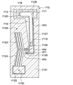
ここで、バルブモジュールY0について、図18、図19、図20、図22、図23、図24を用いて説明する。本実施形態のバルブモジュールY0は、回路基板54bと弁体52の間に配置され、マイクロバルブY1、バルブケーシングY2、3つのOリング62a、62b、62c、2本の電気配線Y6、Y7、および変換プレートY8を有している。
Here, the valve module Y0 will be described with reference to FIGS. 18, 19, 20, 22, 22, 23, and 24. The valve module Y0 of the present embodiment is arranged between the
本実施形態のマイクロバルブY1は、第1冷媒孔Y16、第2冷媒孔Y17、第3冷媒孔Y18の形状が円形でなく矩形である点で、第1実施形態と異なる。本実施形態のマイクロバルブY1は、第2外層Y13において第1冷媒孔Y16が形成される位置が、第1実施形態と異なる。また、本実施形態のマイクロバルブY1は、梁Y127および可動部Y128の形状が、第1実施形態と異なる。マイクロバルブY1の他の構成は、第1実施形態と同じである。 The micro valve Y1 of the present embodiment is different from the first embodiment in that the shapes of the first refrigerant hole Y16, the second refrigerant hole Y17, and the third refrigerant hole Y18 are not circular but rectangular. The microvalve Y1 of the present embodiment is different from the first embodiment in the position where the first refrigerant hole Y16 is formed in the second outer layer Y13. Further, in the micro valve Y1 of the present embodiment, the shapes of the beam Y127 and the movable portion Y128 are different from those of the first embodiment. Other configurations of the microvalve Y1 are the same as in the first embodiment.
梁Y127、可動部Y128が第1実施形態と異なるのは、図22、図23、図24に示すように、可動部Y128と共に中間層Y12の表裏に貫通する貫通孔Y120を囲む枠形状となっている点である。 As shown in FIGS. 22, 23, and 24, the beam Y127 and the movable portion Y128 are different from the first embodiment in the frame shape surrounding the through hole Y120 penetrating the front and back of the intermediate layer Y12 together with the movable portion Y128. It is a point.
そして、第1冷媒孔Y16は、その貫通孔Y120のうち梁Y127に囲まれた部分と、第1外層Y11、中間層Y12、第2外層Y13の積層方向に重なる。そして第1冷媒孔Y16は、可動部Y128とアームY126から等距離の位置よりもアームY126に近い位置に配置されている。梁Y127、可動部Y128のその他の構成は、第1実施形態と同じである。 The first refrigerant hole Y16 overlaps the portion of the through hole Y120 surrounded by the beam Y127 in the stacking direction of the first outer layer Y11, the intermediate layer Y12, and the second outer layer Y13. The first refrigerant hole Y16 is arranged at a position closer to the arm Y126 than a position equidistant from the movable portion Y128 and the arm Y126. Other configurations of the beam Y127 and the movable portion Y128 are the same as those of the first embodiment.
マイクロバルブY1の作動の形態は、第1実施形態と同様である。可動部Y128が非通電時位置にあっても、最大通電時位置にあっても、どの中間位置にあっても、第1冷媒孔Y16と貫通孔Y120は第1外層Y11、中間層Y12、第2外層Y13の積層方向に重なるからである。可動部Y128の位置にかかわらず、第1冷媒孔Y16は冷媒室Y19の貫通孔Y120に連通する。第2冷媒孔Y17、第3冷媒孔Y18の連通、遮断の態様については、第1実施形態と同様である。 The mode of operation of the micro valve Y1 is the same as that of the first embodiment. Regardless of whether the movable portion Y128 is in the non-energized position, the maximum energized position, or any intermediate position, the first refrigerant hole Y16 and the through hole Y120 are the first outer layer Y11, the intermediate layer Y12, and the first. This is because the two outer layers Y13 overlap in the stacking direction. Regardless of the position of the movable portion Y128, the first refrigerant hole Y16 communicates with the through hole Y120 of the refrigerant chamber Y19. The mode of communication and blocking of the second refrigerant hole Y17 and the third refrigerant hole Y18 is the same as that of the first embodiment.
電気配線Y6、Y7は、それぞれ一端がマイクロバルブY1の第1印加点Y129、第2印加点Y130に接続され、貫通孔Y14、Y15を通って、他端で回路基板54bにプリントされたパターンに接続される。回路基板54bに実装されたドライバ回路54dは、当該パターンに接続されている。これにより、電気配線Y6、Y7を通して、ドライバ回路54dからマイクロバルブY1に電力が供給可能となる。互いに対向するマイクロバルブY1と回路基板54bの間には空隙が介在するので、電気配線Y6、Y7の配策が容易である。
One end of the electrical wiring Y6 and Y7 is connected to the first application point Y129 and the second application point Y130 of the microvalve Y1, respectively, and the electrical wiring Y6 and Y7 pass through the through holes Y14 and Y15 and have a pattern printed on the
変換プレートY8は、第1実施形態と同様、マイクロバルブY1とバルブケーシングY2の間に配置されており、その表裏に貫通する流路Y81、Y82、Y83が形成されている。これら流路Y81、Y82は、冷媒孔Y16、Y17の配置関係と、連通孔YV1、YV2間の配置関係との違いを、吸収する。 The conversion plate Y8 is arranged between the microvalve Y1 and the valve casing Y2 as in the first embodiment, and the flow paths Y81, Y82, and Y83 penetrating the front and back thereof are formed. These flow paths Y81 and Y82 absorb the difference between the arrangement relationship of the refrigerant holes Y16 and Y17 and the arrangement relationship between the communication holes YV1 and YV2.
流路Y81の一端は第1冷媒孔Y16に連通し、他端は後述する第1連通孔YV1に連通する。したがって、第1冷媒孔Y16は流路Y81を介して第1連通孔YV1に連通する。流路Y82の一端は第2冷媒孔Y17に連通し、他端は後述する第2連通孔YV2に連通する。したがって、第2冷媒孔Y17は流路Y82を介して第2連通孔YV2に連通する。流路Y83の一端は第3冷媒孔Y18に連通するが、図20に示すように、流路Y83の他端はバルブケーシングY2によって堰き止められている。tうまり、第3冷媒孔Y18は実質的に塞がれている。 One end of the flow path Y81 communicates with the first refrigerant hole Y16, and the other end communicates with the first communication hole YV1 described later. Therefore, the first refrigerant hole Y16 communicates with the first communication hole YV1 via the flow path Y81. One end of the flow path Y82 communicates with the second refrigerant hole Y17, and the other end communicates with the second communication hole YV2 described later. Therefore, the second refrigerant hole Y17 communicates with the second communication hole YV2 via the flow path Y82. One end of the flow path Y83 communicates with the third refrigerant hole Y18, but as shown in FIG. 20, the other end of the flow path Y83 is blocked by the valve casing Y2. The third refrigerant hole Y18 is substantially closed.
バルブケーシングY2は、第1実施形態と同様、マイクロバルブY1および変換プレートY8を収容してマイクロバルブY1とボディ51の線膨張係数の違いを吸収する樹脂製のケーシングである。また、バルブケーシングY2は、マイクロバルブY1を囲むベース部Y20と、マイクロバルブY1から突出する柱形状の第1突出部Y21、第2突出部Y22を有する。第1突出部Y21は制御圧パイプに対応し、第2突出部Y22は低圧パイプに対応する。ベース部Y20、第1突出部Y21、第2突出部Y22は、一体に形成されてもよいし、されなくてもよい。
Similar to the first embodiment, the valve casing Y2 is a resin casing that accommodates the microvalve Y1 and the conversion plate Y8 and absorbs the difference in linear expansion coefficient between the microvalve Y1 and the
ベース部Y20は、ケーシング54aとボディ51の間に配置され、ボディ51に形成された開口51tを囲むように固定部63によって固定される。開口51tは、ボディ51に形成され、ケーシング54aに囲まれる空間から蒸発後冷媒通路51fに貫通する。
The base portion Y20 is arranged between the
第1突出部Y21は、一端においてベース部Y20に接続されると共に変換プレートY8に接し、開口51tおよび蒸発後冷媒通路51fを貫通して伸び、他端において収容孔58内に嵌っている。このように、第1突出部Y21は、蒸発後冷媒通路51fをマイクロバルブY1の側から圧力室58aの側へ貫通する。
The first protruding portion Y21 is connected to the base portion Y20 at one end and is in contact with the conversion plate Y8, extends through the
第2突出部Y22は、一端においてベース部Y20に接続されると共に変換プレートY8に接し、開口51tおよび蒸発後冷媒通路51fを貫通して伸び、他端において連通孔57内に嵌っている。このように、第2突出部Y22は、蒸発後冷媒通路51fをマイクロバルブY1の側から圧力室58aの側へ貫通する。第1突出部Y21、第2突出部Y22の伸びる方向は、幅方向に対しても厚み方向に対しても交差する。より具体的には、第1突出部Y21、第2突出部Y22の伸びる方向は、縦方向である。
The second protruding portion Y22 is connected to the base portion Y20 at one end and is in contact with the conversion plate Y8, extends through the
第1突出部Y21と第2突出部Y22は、蒸発後冷媒通路51fにおいて、幅方向(すなわち、蒸発後冷媒通路51f内を冷媒が流れる方向)に並んで配置されている。この並びにより、蒸発後冷媒通路51f内における冷媒の圧力損失が低減される。第1突出部Y21と第2突出部Y22は、開口51t内部においては、互いに一体に接続されている。そして、開口51t内の第1突出部Y21および第2突出部Y22の外周に、Oリング62cが配置されている。Oリング62cは、第1突出部Y21および第2突出部Y22の外周と開口51tの内壁の両方に接触することで、ケーシング54aに囲まれた空間と蒸発後冷媒通路51fとの間をシールする。
The first protruding portion Y21 and the second protruding portion Y22 are arranged side by side in the width direction (that is, the direction in which the refrigerant flows in the after
また、収容孔58内の第1突出部Y21の外周に、Oリング62aが配置されている。Oリング62aは、第1突出部Y21の外周と収容孔58の内壁の両方に接触することで、蒸発後冷媒通路51fと圧力室58aの間をシールする。また、連通孔57内の第2突出部Y22の外周に、Oリング62bが配置されている。Oリング62bは、第2突出部Y22の外周と連通孔57の内壁の両方に接触することで、蒸発後冷媒通路51fと高圧冷媒通路51cの間をシールする。
Further, an O-
また、第1突出部Y21の内部には、第1連通孔YV1が形成されている。第1連通孔YV1は、制御圧導入孔に対応する。第1連通孔YV1は、蒸発後冷媒通路51fよりもマイクロバルブY1側において第1冷媒孔Y16に連通し、蒸発後冷媒通路51fよりも圧力室58a側において圧力室58aに連通する。このように、蒸発後冷媒通路51fを貫通する第1突出部Y21内に第1連通孔YV1が形成されることで、ボディ51の厚み方向の体格を抑えながら、圧力室58aに導入される冷媒と蒸発後冷媒通路51fを流れる冷媒の干渉を防止できる。
Further, a first communication hole YV1 is formed inside the first protrusion Y21. The first communication hole YV1 corresponds to the control pressure introduction hole. The first communication hole YV1 communicates with the first refrigerant hole Y16 on the microvalve Y1 side of the after
また、第2突出部Y22の内部には、第2連通孔YV2が形成されている。第2連通孔YV2は、高圧導入孔に対応する。第2連通孔YV2は、蒸発後冷媒通路51fよりもマイクロバルブY1側において第2冷媒孔Y17に連通し、蒸発後冷媒通路51fよりも高圧冷媒通路51c側において連通孔57を介して高圧冷媒通路51cに連通する。このように、蒸発後冷媒通路51fを貫通する第2突出部Y22内に第2連通孔YV2が形成されることで、ボディ51の厚み方向の体格を抑えながら、高圧冷媒と蒸発後冷媒通路51fを流れる低圧冷媒の干渉を防止できる。
Further, a second communication hole YV2 is formed inside the second protrusion Y22. The second communication hole YV2 corresponds to the high pressure introduction hole. The second communication hole YV2 communicates with the second refrigerant hole Y17 on the microvalve Y1 side of the after
膨張弁5が上記のような構成となっていることで、回路基板54b、マイクロバルブY1、第1突出部Y21、圧力室58a、圧力伝達部65、弁体52、コイルバネ53、荷重調整部67が、この順に縦方向に一列に並ぶ。また、マイクロバルブY1、蒸発後冷媒通路51f、圧力室58a、低圧冷媒通路51k、弁室51gも、この順に縦方向に一列に並ぶ。
Since the
以下、このような構成の冷凍サイクル1の作動について、第1実施形態と異なる点を中心に説明する。なお、第3冷媒孔Y18は、開口しても開口しなくても、貫通孔Y120を他の冷媒流路と連通させることはない。また、第1冷媒孔Y16は、可動部Y128の位置によらず常に開口するので、マイクロバルブY1の貫通孔Y120は第1連通孔YV1を介して収容孔58と常に連通する。
Hereinafter, the operation of the
[非稼働時]
まず、冷凍サイクルの非稼働時について説明する。この場合、冷凍サイクル1の各装置の作動、非作動および通電、非通電は、第1実施形態と同じである。この場合、第2連通孔YV2とマイクロバルブY1の貫通孔Y120の間が遮断される。
[Not in operation]
First, the non-operating state of the refrigeration cycle will be described. In this case, the operation, non-operation, energization, and non-energization of each device of the
またこのとき、第1実施形態と同様、レシーバ4と膨張弁5の間の冷媒の圧力と、膨張弁5と蒸発器6の間の冷媒の圧力は互いに等しい。したがって、高圧冷媒通路51cにおける冷媒の圧力と低圧冷媒通路51kにおける冷媒の圧力も互いに等しい。
At this time, as in the first embodiment, the pressure of the refrigerant between the
また、低圧連通流路58bを介して低圧冷媒通路51kと収容孔58とが長時間連通しているので、収容孔58の圧力は低圧冷媒通路51kの圧力と同じになる。また、弁室51gの圧力は低圧冷媒通路51kの圧力と同じになる。したがって、コイルバネ53の弾性力とコイルバネ64の弾性力とのつり合いにより、図26に示すように、弁体52は弁座51jに接触し、絞り通路51hが閉じられる。
Further, since the low-pressure
[稼働時]
次に、冷凍サイクルが稼働している状態について説明する。この場合、圧縮機2、送風機8が作動する。これにより、高圧冷媒通路51cにおける冷媒の圧力が、低圧冷媒通路51kにおける冷媒の圧力よりも高くなる。また、複合センサ54c、ドライバ回路54dも作動する。したがってドライバ回路54dから電気配線Y6、Y7を介してマイクロバルブY1に、必要に応じて通電が行われる。
[During operation]
Next, the state in which the refrigeration cycle is in operation will be described. In this case, the
具体的には、蒸発後冷媒通路51fを通る冷媒の圧力と温度を、複合センサ54cが検出する。すなわち、複合センサ54cの感温部が、蒸発後冷媒通路51fを通る冷媒の圧力および温度にそれぞれ応じた圧力信号および温度信号を出力する。ドライバ回路54dは、その圧力信号および温度信号を取得し、取得した圧力信号と温度信号に応じて、電気配線Y6、Y7に供給する電力を決定する。なお、以下では、ドライバ回路54dは、電気配線Y6、Y7に供給する電力を、最大電圧一定のPWM制御で行うものとして説明する。したがって、ドライバ回路54dは、取得した圧力信号と温度信号に応じて、蒸発器6から流出した低圧冷媒の過熱度が所定の一定値になるよう、電気配線Y6、Y7に印加する電圧のデューティ比を決定する。
Specifically, the
具体的には、ドライバ回路54dは、圧力信号が示す圧力が一定で温度信号が示す温度が高くなるほど、すなわち、過熱度が高くなるほど、デューティ比を大きくする。これにより、弁体52のリフト量が増大し、加熱度が低下する。また、温度信号が示す温度が一定で圧力信号が示す圧力が高くなるほど、すなわち、過熱度が低くなるほど、デューティ比を小さくする。これにより、弁体52のリフト量が減少し、過熱度が上昇する。
Specifically, the
そして、ドライバ回路54dは、決定したデューティ比で、電気配線Y6、Y7を介して、マイクロバルブY1に電圧を印加する。これによって、蒸発器6から流出した低圧冷媒の過熱度が一定に保たれる。
Then, the
例えば、デューティ比が100%に上昇した場合、第2連通孔YV2と第1連通孔YV1とがマイクロバルブY1を介して連通する。したがって、高圧冷媒通路51cにおける高圧冷媒が、連通孔57、第2連通孔YV2、流路Y82、第2冷媒孔Y17を介してマイクロバルブY1内に導入される。そして、当該高圧冷媒が、マイクロバルブY1の第1冷媒孔Y16から、流路Y81、第1連通孔YV1を介して、圧力室58aに印加される。
For example, when the duty ratio rises to 100%, the second communication hole YV2 and the first communication hole YV1 communicate with each other via the micro valve Y1. Therefore, the high-pressure refrigerant in the high-
これにより、圧力室58aの圧力が高圧になり、圧力伝達部65を介して弁体52に伝達される力が最大になる。その結果、図25に示すように、絞り通路51hの開度およびリフト量が最大の状態になる。なお、圧力室58aと低圧冷媒通路51kは低圧連通流路58bを介して連通しているが、低圧連通流路58bには絞り部58cが形成されているので、圧力室58aと低圧冷媒通路51kの圧力差は維持される。
As a result, the pressure in the
また例えば、デューティ比がゼロより大きく100%より小さい場合、第2連通孔YV2と第1連通孔YV1とがマイクロバルブY1を介して連通する。ただし、第2冷媒孔Y17の開度は、デューティ比が100%のときよりは小さく、かつ、デューティ比が大きくなるほど大きくなる。したがって、マイクロバルブY1の貫通孔Y120における圧力は、第1冷媒孔Y16による減圧効果により、デューティ比が小さくなるほど低くなる。 Further, for example, when the duty ratio is larger than zero and smaller than 100%, the second communication hole YV2 and the first communication hole YV1 communicate with each other via the micro valve Y1. However, the opening degree of the second refrigerant hole Y17 is smaller than when the duty ratio is 100%, and becomes larger as the duty ratio becomes larger. Therefore, the pressure in the through hole Y120 of the microvalve Y1 becomes lower as the duty ratio becomes smaller due to the depressurizing effect of the first refrigerant hole Y16.
したがって、マイクロバルブY1の第1冷媒孔Y16から第1連通孔YV1を介して圧力室58aに出力される冷媒圧力は、デューティ比が小さくなるほど低くなる。これにより、圧力伝達部65を介して弁体52に伝達される力が、最大よりも小さく最小よりも大きい値になる。そして、絞り通路51hの開度およびリフト量は、最小よりも大きくかつ最大よりも小さい範囲で、デューティ比が小さくなるほど小さくなる。
Therefore, the refrigerant pressure output from the first refrigerant hole Y16 of the microvalve Y1 to the
また例えば、デューティ比が0%に低下した場合、第2冷媒孔Y17が遮断される。すると、高圧冷媒通路51cからマイクロバルブY1内の貫通孔Y120への冷媒の流れが断たれる。すると、圧力室58a内の冷媒が低圧連通流路58bを通って徐々に低圧冷媒通路51kに流出すると共に、圧力室58a内の冷媒の圧力が低下する。そして最終的に、圧力室58a内の冷媒の圧力が低圧冷媒通路51kの圧力と同じになる。したがって、圧力伝達部65から弁体52に伝達される力も徐々に減少することでリフト量および絞り通路51hの開度が低下し、最終的に、図26のようにゼロになる。
Further, for example, when the duty ratio drops to 0%, the second refrigerant hole Y17 is shut off. Then, the flow of the refrigerant from the high-
なお、上述の通り、冷凍サイクル1の稼働時において、デューティ比が0より大きく弁体52のリフト量がゼロより大きい場合、圧力室58aと低圧冷媒通路51kの間に圧力差が発生する。そしてこのとき、高圧冷媒通路51cから、連通孔57、第2連通孔YV2、第2冷媒孔Y17、貫通孔Y120、第1冷媒孔Y16、第1連通孔YV1、圧力室58a、低圧連通流路58bをこの順に通って、低圧冷媒通路51kに、冷媒が流れる。その際、上述の通り、絞り部58cの減圧作用により、圧力室58aと低圧冷媒通路51kの間の圧力差はあり続ける。ただし、このような冷媒の流量は、弁室51gを介して高圧冷媒通路51cから低圧冷媒通路51kに流れる冷媒の流量よりも遙かに少ない。
As described above, when the duty ratio is larger than 0 and the lift amount of the
このように、低圧連通流路58bは、マイクロバルブY1から流出する冷媒を高圧冷媒通路51cに導く。これにより、低圧連通流路58bから低圧冷媒通路51kに導かれた冷媒は、蒸発器6に流入する。したがって、第1冷媒孔Y16から低圧側に導かれた冷媒が蒸発器6に流入しない場合に比べて、熱交換に寄与しない冷媒を低減することができる。ひいては、冷媒を無駄に使用する可能性が低減され、冷凍サイクル1の効率が向上する。
In this way, the low-pressure
また、第1冷媒孔Y16は、低圧冷媒通路51kの低圧よりも高い制御圧を圧力室58aに出力し、低圧連通流路58bは、第1冷媒孔Y16から流出した冷媒を低圧冷媒通路51kに導く。そして、低圧連通流路58bには、低圧連通流路58bに沿って流路断面積が低下する絞り部58cが設けられている。
Further, the first refrigerant hole Y16 outputs a control pressure higher than the low pressure of the low pressure
このように、低圧連通流路58bが第1冷媒孔Y16から流出した冷媒を低圧冷媒通路51kに導くように構成されていることで、マイクロバルブY1の第3冷媒孔Y18を低圧連通流路に連通させる必要がなくなる。また、このような構成において低圧連通流路58bに絞り部58cが形成されていることで、絞り部58cの前後で圧力差を生じさせることができるので、制御圧を出力するという第1冷媒孔Y16の機能が損ねられる可能性が低減される。
As described above, the low-pressure
また、圧力伝達部65は、圧力室58aから低圧冷媒通路51kを通って弁体52まで伸び、低圧連通流路58bは、圧力伝達部65の内部に形成されて圧力室58aから低圧冷媒通路51kまで連通する。このように、圧力伝達部65が圧力室58aの制御圧を受けると共に低圧冷媒通路51kを通ることを利用し、圧力室58aから低圧冷媒通路51kまで連通する低圧連通流路58bを形成することで、低圧連通流路58bのためだけの部材を設ける必要がなくなる。
Further, the
また、複合センサ54c、マイクロバルブY1、ドライバ回路54dは、蒸発後冷媒通路51fを基準として弁体52とは反対側に配置される。このようになっていることで、センサ、制御弁部品およびドライバ回路間の電気的配線の配策が容易になる。
Further, the
また、ボディ51において、マイクロバルブY1、蒸発後冷媒通路51f、圧力室58aが、この順に縦方向に一列に並んで配置されている。そして、制御圧パイプである第1突出部Y21は、蒸発後冷媒通路51fをマイクロバルブY1の側から圧力室58aの側へ貫通する。そして、第1突出部Y21には、蒸発後冷媒通路51fよりもマイクロバルブY1の側において第1冷媒孔Y16に連通し、蒸発後冷媒通路51fよりも圧力室58a側において圧力室58aに連通する第1連通孔YV1が形成される。
Further, in the
このような構成により、蒸発後冷媒通路51fを貫通する第1突出部Y21に形成された第1連通孔YV1を介して、マイクロバルブY1から制御圧を及ぼすことができる。したがって、マイクロバルブY1の機能も維持しつつ、複合センサ54c、マイクロバルブY1およびドライバ回路54d間の電気的配線の配策が容易になる。そして、マイクロバルブY1、厚み方向における弁装置の体格を抑制することができる。
With such a configuration, the control pressure can be applied from the micro valve Y1 through the first communication hole YV1 formed in the first protrusion Y21 penetrating the
(第5実施形態)
次に第5実施形態について、図27、図28を用いて説明する。本実施形態に係る冷凍サイクル1は、第4実施形態の冷凍サイクル1に対して、低圧連通流路58bの配設形態が変更されている。その他の構成は、第4実施形態と同じである。
(Fifth Embodiment)
Next, the fifth embodiment will be described with reference to FIGS. 27 and 28. In the
本実施形態の低圧連通流路58bは、圧力伝達部65の内部に形成されているのではなく、圧力伝達部65の外周面と収容孔58の内周面の間の隙間という形態で、配設される。この低圧連通流路58bは、一端において圧力室58aに連通し、他端において低圧冷媒通路51kに連通する。
The low-voltage
また、低圧連通流路58bが圧力室58aと低圧冷媒通路51kの両方に連通するために、シールリング66には、図28に示すように、冷媒が通過可能なスリット66aが形成されている。このスリット66aは、縦方向(ずなわち、図28の紙面に直交する方向)に貫通している。このスリット66aは、低圧連通流路58bの一部であり、スリット66aの他の部分よりも流路断面積が小さい。したがって、スリット66aは、圧力室58aと低圧冷媒通路51kの間に圧力差を発生させる絞り部として機能する。
Further, in order for the low-pressure
本実施形態における冷凍サイクル1の作動は、第4実施形態の低圧連通流路58b、スリット66aを本実施形態の低圧連通流路58b、スリット66aに置き換えたものとなる。
The operation of the
以上のように、収容孔58は圧力室58aを含むと共に低圧冷媒通路51kに連通すること、圧力伝達部65が圧力室58aの制御圧を受けると共に低圧冷媒通路51kを通ることを利用し、収容孔58の内壁面と圧力伝達部65の外周面との間の隙間に低圧連通流路58bを設けることができる。このようにすることで、低圧連通流路58bのためだけの部材を設ける必要がなくなる。また、シールリング66を絞り部として利用することができるので、絞り部を設けるためにボディ51、圧力伝達部65の形状を複雑にする必要がなくなる。また、本実施形態において第4実施形態と同様の構成からは、第4実施形態と同様の効果を得ることができる。
As described above, the
(第6実施形態)
次に第6実施形態について、図29を用いて説明する。本実施形態に係る冷凍サイクル1は、第4実施形態の冷凍サイクル1に対して、低圧連通流路58bの配設形態が変更されている。その他の構成は、第4実施形態と同じである。
(Sixth Embodiment)
Next, the sixth embodiment will be described with reference to FIG. 29. In the
本実施形態の低圧連通流路58bは、圧力伝達部65の内部ではなく、圧力室58aから圧力伝達部65をバイパスして低圧冷媒通路51kに連通するよう、ボディ51に形成されている。この低圧連通流路58bは、圧力室58aにおいて収容孔58から分岐して、ボディ51内を低圧冷媒通路51kまで伸びている。
The low-pressure
また、低圧連通流路58bにおける圧力室58aと低圧冷媒通路51kの間には、第4実施形態と同様に流路断面積が前後よりも小さい絞り部58cが形成されている。このような絞り部58cにより、その前後で圧力差を生じさせることができる。つまり、圧力室58aと低圧冷媒通路51kの間で圧力差を生じさせることができる。本実施形態において第4実施形態と同様の構成からは、第4実施形態と同様の効果を得ることができる。
Further, between the
(第7実施形態)
次に第7実施形態について、図30を用いて説明する。本実施形態に係る冷凍サイクル1は、第4実施形態の冷凍サイクル1に対して、バルブケーシングY2の構成、変換プレートY8の構成、低圧連通流路の配設形態、およびボディ51の構造が、異なっている。その他の構成は、第4実施形態と同じである。以下、第4実施形態と異なる点を中心に説明する。
(7th Embodiment)
Next, the seventh embodiment will be described with reference to FIG. In the
本実施形態のバルブケーシングY2は、第4実施形態と同様のベース部Y20、第1突出部Y21、第2突出部Y22、Oリング62a、62b、62cに加え、第3突出部Y23を有する。第3突出部Y23は低圧パイプに対応する。ベース部Y20、第1突出部Y21、第2突出部Y22、第3突出部Y23は、一体に形成されてもよいし、されなくてもよい。
The valve casing Y2 of the present embodiment has a third protruding portion Y23 in addition to the base portion Y20, the first protruding portion Y21, the second protruding portion Y22, the O-
第3突出部Y23は、一端においてベース部Y20に接続されると共に変換プレートY8に接し、開口51tおよび蒸発後冷媒通路51fを貫通して伸び、他端において連通孔59内に嵌っている。連通孔59は、本実施形態においてボディ51に形成された孔であり、一端は蒸発後冷媒通路51fに連通し、他端は低圧冷媒通路51kに連通する。
The third protruding portion Y23 is connected to the base portion Y20 at one end and is in contact with the conversion plate Y8, extends through the
このように、第3突出部Y23は、蒸発後冷媒通路51fをマイクロバルブY1の側から圧力室58aおよび低圧冷媒通路51kの側へ貫通する。第3突出部Y23の伸びる方向は、幅方向にも厚み方向にも交差し、より具体的には、縦方向である。第1突出部Y21、第2突出部Y22、第3突出部Y23は、蒸発後冷媒通路51fにおいて、幅方向(すなわち、蒸発後冷媒通路51f内を冷媒が流れる方向)に並んで配置されている。この並びにより、蒸発後冷媒通路51f内における冷媒の圧力損失が低減される。
In this way, the third protruding portion Y23 penetrates the
第1突出部Y21、第2突出部Y22、第3突出部Y23は、開口51t内部においては、互いに一体に接続されている。そして、開口51t内の第1突出部Y21、第2突出部Y22、第3突出部Y23の外周に、第4実施形態と同様のOリング62cが配置されている。
The first protruding portion Y21, the second protruding portion Y22, and the third protruding portion Y23 are integrally connected to each other inside the
また、連通孔59内の第3突出部Y23の外周に、Oリング62dが配置されている。Oリング62dは、第3突出部Y23の外周と連通孔59の内壁の両方に接触することで、蒸発後冷媒通路51fと低圧冷媒通路51kの間をシールする。
Further, an O-
また、第3突出部Y23の内部には、第3連通孔YV3が形成されている。第3連通孔YV3は、低圧導入孔に対応する。第3連通孔YV3は、蒸発後冷媒通路51fよりもマイクロバルブY1側において第3冷媒孔Y18に連通し、蒸発後冷媒通路51fよりも低圧冷媒通路51k側において連通孔59を介して低圧冷媒通路51kに連通する。このように、蒸発後冷媒通路51fを貫通する第3突出部Y23内に第3連通孔YV3が形成されることで、ボディ51の厚み方向の体格を抑えながら、蒸発後冷媒通路51fの冷媒と低圧冷媒通路51kの冷媒とが混合してしまう可能性を低減できる。本実施形態においては、この第3連通孔YV3が、低圧連通流路に相当する。
Further, a third communication hole YV3 is formed inside the third protrusion Y23. The third communication hole YV3 corresponds to the low pressure introduction hole. The third communication hole YV3 communicates with the third refrigerant hole Y18 on the microvalve Y1 side of the after
また、本実施形態においては、変換プレートY8の流路Y83は、一端において第3冷媒孔Y18に連通し、他端において第3連通孔YV3に連通する。これにより、第3連通孔YV3と第3冷媒孔Y18の連通が実現する。したがって、第1冷媒孔Y16、第2冷媒孔Y17、第3冷媒孔Y18と第1連通孔YV1、第2連通孔YV2、第3連通孔YV3の接続関係は、第1実施形態と同じである。 Further, in the present embodiment, the flow path Y83 of the conversion plate Y8 communicates with the third refrigerant hole Y18 at one end and communicates with the third communication hole YV3 at the other end. As a result, the communication between the third communication hole YV3 and the third refrigerant hole Y18 is realized. Therefore, the connection relationship between the first refrigerant hole Y16, the second refrigerant hole Y17, the third refrigerant hole Y18 and the first communication hole YV1, the second communication hole YV2, and the third communication hole YV3 is the same as that of the first embodiment. ..
なお、本実施形態のマイクロバルブY1は、第4実施形態と同じマイクロバルブY1であってもよいし、第1実施形態と同じマイクロバルブY1であってもよい。どちらの場合であっても、マイクロバルブY1の可動部Y128は、増幅部(すなわちアームY126、梁Y127)によって増幅された変位が伝達されて冷媒室Y19内で動く。そして、この動きにより、貫通孔Y120に対する第2冷媒孔Y17、第3冷媒孔Y18の開度を調整することができる。 The microvalve Y1 of the present embodiment may be the same microvalve Y1 as the fourth embodiment or the same microvalve Y1 as the first embodiment. In either case, the movable portion Y128 of the microvalve Y1 moves in the refrigerant chamber Y19 by transmitting the displacement amplified by the amplification portion (that is, the arm Y126 and the beam Y127). Then, by this movement, the opening degree of the second refrigerant hole Y17 and the third refrigerant hole Y18 with respect to the through hole Y120 can be adjusted.
また、本実施形態の圧力伝達部65には、低圧連通流路58bが形成されていない。したがって、本実施形態の圧力室58aは、膨張弁5内においてマイクロバルブY1を介さず高圧冷媒通路51c、低圧冷媒通路51kに連通することはない。
Further, the
このような構成の冷凍サイクル1の作動について、以下説明する。
[非稼働時]
まず、冷凍サイクルの非稼働時について説明する。この場合、冷凍サイクル1の各装置の作動、非作動および通電、非通電は、第1実施形態と同じである。したがってこの場合、
第3連通孔YV3と第1連通孔YV1とがマイクロバルブY1を介して連通し、第2連通孔YV2とマイクロバルブY1の貫通孔Y120の間が遮断される。
The operation of the
[Not in operation]
First, the non-operating state of the refrigeration cycle will be described. In this case, the operation, non-operation, energization, and non-energization of each device of the
The third communication hole YV3 and the first communication hole YV1 communicate with each other via the micro valve Y1, and the space between the second communication hole YV2 and the through hole Y120 of the micro valve Y1 is blocked.
またこのとき、第1実施形態と同様、レシーバ4と膨張弁5の間の冷媒の圧力と、膨張弁5と蒸発器6の間の冷媒の圧力は互いに等しい。したがって、高圧冷媒通路51cにおける冷媒の圧力と低圧冷媒通路51kにおける冷媒の圧力も互いに等しい。また、弁室51gの圧力は低圧冷媒通路51kの圧力と同じになる。したがって、コイルバネ53の弾性力とコイルバネ64の弾性力とのつり合いにより、弁体52は弁座51jに接触し、絞り通路51hが閉じられる。
At this time, as in the first embodiment, the pressure of the refrigerant between the
[稼働時]
次に、冷凍サイクルが稼働している状態について説明する。この場合、圧縮機2、送風機8が作動する。これにより、高圧冷媒通路51cにおける冷媒の圧力が、低圧冷媒通路51kにおける冷媒の圧力よりも高くなる。また、複合センサ54c、ドライバ回路54dも作動する。したがってドライバ回路54dから電気配線Y6、Y7を介してマイクロバルブY1に、必要に応じて通電が行われる。その際、第4実施形態と同様の作動により、ドライバ回路54dは、取得した圧力信号と温度信号に応じて、蒸発器6から流出した低圧冷媒の過熱度が所定の一定値になるよう、電気配線Y6、Y7に印加する電圧のデューティ比を決定する。
[During operation]
Next, the state in which the refrigeration cycle is in operation will be described. In this case, the
例えば、デューティ比が100%の場合、第1実施形態と同様、第2連通孔YV2と第1連通孔YV1とがマイクロバルブY1を介して連通し、第3連通孔YV3とマイクロバルブY1の貫通孔Y120の間が遮断される。したがって、高圧冷媒通路51cにおける高圧冷媒が、連通孔57、第2連通孔YV2、流路Y82、第2冷媒孔Y17を介してマイクロバルブY1内に導入される。そして、当該高圧冷媒が、マイクロバルブY1の第1冷媒孔Y16から、流路Y81、第1連通孔YV1を介して、圧力室58aに印加される。これにより、圧力室58aの圧力が高圧になり、圧力伝達部65を介して弁体52に伝達される力が最大になる。その結果、絞り通路51hの開度およびリフト量が最大の状態になる。
For example, when the duty ratio is 100%, the second communication hole YV2 and the first communication hole YV1 communicate with each other through the micro valve Y1 and penetrate the third communication hole YV3 and the micro valve Y1 as in the first embodiment. The space between the holes Y120 is blocked. Therefore, the high-pressure refrigerant in the high-
また例えば、デューティ比がゼロより大きく100%より小さい場合、第1実施形態と同様、第2連通孔YV2と第1連通孔YV1とがマイクロバルブY1を介して連通すると共に、第3連通孔YV3と第1連通孔YV1とがマイクロバルブY1を介して連通する。このとき、マイクロバルブY1の第1冷媒孔Y16から圧力室58aに出力される制御圧は、高圧冷媒通路51cの高圧よりも低く、かつ、低圧冷媒通路51kの低圧よりも高くなる。そして、デューティ比が小さくなるほど、第2冷媒孔Y17の開度が小さくなり第3冷媒孔Y18の開度が大きくなる。したがって、マイクロバルブY1の第1冷媒孔Y16から圧力室58aに出力される制御圧は、第2冷媒孔Y17と第3冷媒孔Y18の減圧作用により、デューティ比が小さくなるほど低下する。
Further, for example, when the duty ratio is larger than zero and smaller than 100%, the second communication hole YV2 and the first communication hole YV1 communicate with each other via the microvalve Y1 and the third communication hole YV3, as in the first embodiment. And the first communication hole YV1 communicate with each other via the micro valve Y1. At this time, the control pressure output from the first refrigerant hole Y16 of the microvalve Y1 to the
これにより、圧力伝達部65を介して弁体52に伝達される力が、最大よりも小さく最小よりも大きい値になる。そして、絞り通路51hの開度およびリフト量は、最小よりも大きくかつ最大よりも小さい範囲で、デューティ比が小さくなるほど小さくなる。なお、デューティ比がゼロより大きく100%より小さい場合、冷媒は、高圧冷媒通路51cから第2連通孔YV2、マイクロバルブY1、第3連通孔YV3をこの順に通って、低圧冷媒通路51kに流れる。ただし、この流れる量は、弁室51gを通って高圧冷媒通路51cから低圧冷媒通路51kに流れる量よりも遙かに少ない。
As a result, the force transmitted to the
また例えば、デューティ比がゼロの場合、第1実施形態と同様、第3連通孔YV3と第1連通孔YV1とがマイクロバルブY1を介して連通し、第2連通孔YV2とマイクロバルブY1の貫通孔Y120の間が遮断される。したがって、低圧冷媒通路51kにおける低圧冷媒が、連通孔59、第3連通孔YV3、流路Y83、第3冷媒孔Y18を介してマイクロバルブY1内に導入される。そして、当該低圧冷媒が、マイクロバルブY1の第1冷媒孔Y16から、流路Y81、第1連通孔YV1を介して、圧力室58aに印加される。これにより、圧力室58aの圧力が低圧になり、弁体52は弁座51jに接触し、絞り通路51hが閉じられる。
Further, for example, when the duty ratio is zero, the third communication hole YV3 and the first communication hole YV1 communicate with each other through the micro valve Y1 and penetrate the second communication hole YV2 and the micro valve Y1 as in the first embodiment. The space between the holes Y120 is blocked. Therefore, the low-pressure refrigerant in the low-pressure
また、圧連通流路に対応する第3連通孔YV3は、第3冷媒孔Y18から蒸発後冷媒通路51fを越えて低圧冷媒通路51kに連通している。本実施形態では、第4実施形態と同様、ボディ51の外部からコイルバネ53の弾性力の調整のための操作を受け付け可能で蒸発後冷媒通路51fを基準として弁体52と同じ側にある荷重調整部67が設けられている。この荷重調整部67との干渉を避けるように、マイクロバルブY1が蒸発後冷媒通路51fを基準として荷重調整部67、弁体52、低圧冷媒通路51kとは反対側にある。この場合、第3連通孔YV3を、第3冷媒孔Y18から蒸発後冷媒通路51fを越えて低圧冷媒通路51kに連通させることで、マイクロバルブY1と荷重調整部67との干渉を避けつつ、マイクロバルブY1から低圧冷媒通路51kに冷媒を導くことができる。
Further, the third communication hole YV3 corresponding to the pressure communication flow path communicates with the low pressure
また、蒸発後冷媒通路51fをマイクロバルブY1の側から低圧冷媒通路51kの側へ貫通する第3突出部Y23の内部に、低圧連通流路である第3連通孔YV3が形成されている。このようになっていることで、蒸発後冷媒通路51fと第3連通孔YV3が交差しても、両者が流路的に絶縁される。そして、蒸発後冷媒通路51f、圧力室58a、圧力伝達部65、弁体52の並び方向に交差して蒸発後冷媒通路51fの延伸方向に交差する厚み方向における膨張弁5の体格を抑制することができる。また、本実施形態において第4実施形態と同様の構成からは、第4実施形態と同様の効果を得ることができる。
Further, a third communication hole YV3, which is a low pressure communication flow path, is formed inside the third protrusion Y23 that penetrates the
(第8実施形態)
次に第8実施形態について、図31、図32を用いて説明する。本実施形態の冷凍サイクル1は、第7実施形態に対して、バルブケーシングY2の構成、変換プレートY8の構成、低圧連通流路の配設形態、およびボディ51の構造が、異なっている。その他の構成は、第7実施形態と同じである。以下、第4実施形態と異なる点を中心に説明する。
(8th Embodiment)
Next, the eighth embodiment will be described with reference to FIGS. 31 and 32. The
本実施形態のバルブケーシングY2は、第7実施形態のバルブケーシングY2に対して、第3突出部Y23の位置および長さが異なっている。具体的には、第3突出部Y23は、図32に示すように、第2突出部Y22に対して膨張弁5の厚み方向に並んで配置されている。また、本実施形態の第3突出部Y23は、第7実施形態に比べて縦方向の長さが短い。また、第3突出部Y23内に形成されている第3連通孔YV3の長さも、第3突出部Y23が短くなったのに合わせて短くなっている。
The valve casing Y2 of the present embodiment has a different position and length of the third protrusion Y23 from the valve casing Y2 of the seventh embodiment. Specifically, as shown in FIG. 32, the third protruding portion Y23 is arranged side by side with respect to the second protruding portion Y22 in the thickness direction of the
第3連通孔YV3は、一端が変換プレートY8の流路Y83に連通し、他端が迂回流路58dに連通している。迂回流路58dは、図32に示すように、ボディ51に形成され、一端で第3連通孔YV3に連通し、縦方向に伸びた後、厚み方向に伸びて、他端で低圧冷媒通路51kに連通している。また、ボディ51には、迂回流路58dとボディ51の外部空間との間をシールするシール部材62eが取り付けられている。第3連通孔YV3と迂回流路58dから成る流路が、低圧連通流路に相当する。
One end of the third communication hole YV3 communicates with the flow path Y83 of the conversion plate Y8, and the other end communicates with the
この低圧連通流路は、流路Y83から、バルブケーシングY2内およびボディ51内において、蒸発後冷媒通路51fを迂回して低圧冷媒通路51kに連通している。すなわち、低圧連通孔流路は、蒸発後冷媒通路51fに対してボディ51の厚み方向にずれた位置を通ることで、蒸発後冷媒通路を越えて、蒸発後冷媒通路51fよりもマイクロバルブY1側から、蒸発後冷媒通路51fよりも低圧冷媒通路51k側に伸びる。
This low-pressure communication flow path is communicated from the flow path Y83 in the valve casing Y2 and in the
変換プレートY8において、マイクロバルブY1の第1冷媒孔Y16、第2冷媒孔Y17、第3冷媒孔Y18がそれぞれ第1連通孔YV1、第2連通孔YV2、第3連通孔YV3に連通するよう、流路Y81、Y82、Y83がそれぞれ形成されている。これは、第7実施形態と同様である。なお、本実施形態では、連通孔59は形成されていない。
In the conversion plate Y8, the first refrigerant hole Y16, the second refrigerant hole Y17, and the third refrigerant hole Y18 of the micro valve Y1 communicate with the first communication hole YV1, the second communication hole YV2, and the third communication hole YV3, respectively. The flow paths Y81, Y82, and Y83 are formed, respectively. This is the same as the seventh embodiment. In this embodiment, the
本実施形態の作動は、第7実施形態と同じである。ただし、第3冷媒孔Y18が開口したときは、第3冷媒孔Y18、第3連通孔YV3、迂回流路58dを介して冷凍サイクル1と低圧冷媒通路51kが連通する。
The operation of this embodiment is the same as that of the seventh embodiment. However, when the third refrigerant hole Y18 is opened, the refrigerating
このように、低圧連通流路は、ボディ51およびバルブケーシングY2において、蒸発後冷媒通路51fの外部に形成されていることで、第3冷媒孔Y18側から蒸発後冷媒通路51fを迂回して蒸発後冷媒通路51f側に連通している。このようになっていることで、厚み方向におけるボディ51の内部等を利用して、第3冷媒孔Y18から出る冷媒を蒸発後冷媒通路51fを越えて低圧冷媒通路51kに導くことができる。なお、本実施形態において第7実施形態と同様の構成からは、第7実施形態と同様の効果を得ることができる。
As described above, the low-pressure communication flow path is formed outside the after-
(第9実施形態)
次に第9実施形態について、図33、図34、図35を用いて説明する。本実施形態は、第8実施形態に対して、第3冷媒孔Y18が連通する位置が、図35に示すように、低圧冷媒通路51kから蒸発後冷媒通路51fに変更されている。
(9th Embodiment)
Next, the ninth embodiment will be described with reference to FIGS. 33, 34, and 35. In the present embodiment, as shown in FIG. 35, the position where the third refrigerant hole Y18 communicates with the eighth embodiment is changed from the low pressure
具体的には、第8実施形態の迂回流路58dが廃され、第3連通孔YV3の流路Y83とは反対側の端部が蒸発後冷媒通路51fに連通している。冷凍サイクル1の作動中、低圧冷媒通路51kと蒸発後冷媒通路51fはほぼ同じ圧力なので、本実施形態においても、第8実施形態と同様の作動が実現する。なお、本実施形態において第8実施形態と同様の構成からは、第4実施形態と同様の効果を得ることができる。
Specifically, the
(第10実施形態)
次に第10実施形態について、図36を用いて説明する。本実施形態は、第4実施形態に対して、複合センサ54cの配置が異なる。具体的には、複合センサ54cは、バルブモジュールY0と一体に形成されている。
(10th Embodiment)
Next, the tenth embodiment will be described with reference to FIG. 36. In this embodiment, the arrangement of the
より具体的には、複合センサ54cは、開口51t内において、第1突出部Y21と第2突出部Y22の間に挟まれ、不図示の配線を介して、回路基板54bに実装されたドライバ回路54dに接続されている。
More specifically, the
そして、複合センサ54cは、第1突出部Y21および第2突出部Y22の両方に接着等で取り付けられる。これにより、複合センサ54cと第1突出部Y21の間、および、複合センサ54cと第2突出部Y22の間に、ケーシング54aで囲まれた空間と蒸発後冷媒通路51fの間のシールが実現する。
Then, the
以上のように、複合センサ54cとバルブモジュールY0は、一体としてボディ51に組み付けられている。このようになっていることで、複合センサ54cとマイクロバルブY1が別体としてボディ51に組み付けられている場合に比べ、組み付け作業の手間および組み付けのための部品を低減することができる。実際、上記のような構成においては、複合センサ54cをボディ51に組み付けるための部材が不要になる。また、複合センサ54cを蒸発後冷媒通路51fに露出させるための孔を開口51r以外に設ける必要がない。
As described above, the
なお、第4実施形態に対する本実施形態の変更は、他の実施形態にも同様に適用可能である。また、本実施形態において、適用先の実施形態と同様の構成からは、第4実施形態と同様の効果を得ることができる。 It should be noted that the modification of this embodiment to the fourth embodiment can be similarly applied to other embodiments. Further, in the present embodiment, the same effect as that of the fourth embodiment can be obtained from the same configuration as that of the application destination embodiment.
(他の実施形態)
なお、本発明は上記した実施形態に限定されるものではなく、適宜変更が可能である。また、上記各実施形態は、互いに無関係なものではなく、組み合わせが明らかに不可な場合を除き、適宜組み合わせが可能である。また、上記各実施形態において、実施形態を構成する要素は、特に必須であると明示した場合および原理的に明らかに必須であると考えられる場合等を除き、必ずしも必須のものではない。また、上記各実施形態において、実施形態の構成要素の個数、数値、量、範囲等の数値が言及されている場合、特に必須であると明示した場合および原理的に明らかに特定の数に限定される場合等を除き、その特定の数に限定されるものではない。また、上記実施形態において、センサから車両の外部環境情報(例えば車外の湿度)を取得することが記載されている場合、そのセンサを廃し、車両の外部のサーバまたはクラウドからその外部環境情報を受信することも可能である。あるいは、そのセンサを廃し、車両の外部のサーバまたはクラウドからその外部環境情報に関連する関連情報を取得し、取得した関連情報からその外部環境情報を推定することも可能である。特に、ある量について複数個の値が例示されている場合、特に別記した場合および原理的に明らかに不可能な場合を除き、それら複数個の値の間の値を採用することも可能である。また、上記各実施形態において、構成要素等の形状、位置関係等に言及するときは、特に明示した場合および原理的に特定の形状、位置関係等に限定される場合等を除き、その形状、位置関係等に限定されるものではない。また、本発明は、上記各実施形態に対する以下のような変形例および均等範囲の変形例も許容される。なお、以下の変形例は、それぞれ独立に、上記実施形態に適用および不適用を選択できる。すなわち、以下の変形例のうち任意の組み合わせを、上記実施形態に適用することができる。
(Other embodiments)
The present invention is not limited to the above-described embodiment, and can be appropriately modified. Further, the above embodiments are not unrelated to each other, and can be appropriately combined unless the combination is clearly impossible. Further, in each of the above embodiments, the elements constituting the embodiment are not necessarily essential except when it is clearly stated that they are essential or when they are clearly considered to be essential in principle. Further, in each of the above embodiments, when numerical values such as the number, numerical values, quantities, and ranges of the constituent elements of the embodiment are mentioned, when it is clearly stated that they are particularly essential, and when it is clearly limited to a specific number in principle. It is not limited to the specific number except when it is done. Further, in the above embodiment, when it is described that the external environment information of the vehicle (for example, the humidity outside the vehicle) is acquired from the sensor, the sensor is abolished and the external environment information is received from the server or the cloud outside the vehicle. It is also possible to do. Alternatively, it is possible to abolish the sensor, acquire related information related to the external environmental information from a server or cloud outside the vehicle, and estimate the external environmental information from the acquired related information. In particular, when a plurality of values are exemplified for a certain amount, it is also possible to adopt a value between the plurality of values unless otherwise specified or when it is clearly impossible in principle. .. Further, in each of the above embodiments, when the shape, positional relationship, etc. of the constituent elements are referred to, the shape, unless otherwise specified or limited in principle to a specific shape, positional relationship, etc. It is not limited to the positional relationship. Further, the present invention also allows the following modifications and equal range modifications for each of the above embodiments. It should be noted that the following modifications can be independently selected to be applied or not applied to the above embodiment. That is, any combination of the following modifications can be applied to the above embodiment.
(変形例1)
上記各実施形態では、複数本の第1リブY123、複数本の第2リブY124、は、通電されることで発熱し、その発熱によって自らの温度が上昇することで膨張する。しかし、これら部材は、温度が変化すると長さが変化する形状記憶材料から構成されていてもよい。
(Modification 1)
In each of the above embodiments, the plurality of first ribs Y123 and the plurality of second ribs Y124 generate heat when energized, and the heat generation causes the temperature to rise to expand. However, these members may be made of a shape memory material whose length changes as the temperature changes.
(変形例2)
第5実施形態では、電気配線Y6、Y7からマイクロバルブY1への通電が停止したとき、マイクロバルブY1は低圧冷媒通路51kに連通する。しかし、必ずしもこのようになっておらずともよい。例えば、電気配線Y6、Y7からマイクロバルブY1への通電が停止したとき、マイクロバルブY1は高圧冷媒通路51cに連通してもよい。
(Modification 2)
In the fifth embodiment, when the energization from the electric wires Y6 and Y7 to the microvalve Y1 is stopped, the microvalve Y1 communicates with the low pressure
(変形例3)
第3実施形態では、ギャップセンサとしてホール素子55が用いられているが、ギャップセンサとしては、渦電流式のセンサが用いられてもよい。この場合、第3実施形態に対して、磁石56が廃され、ホール素子55がコイルに置き換わる。このコイルには、高周波電流が流れる。その結果、このコイルの周囲には、高周波磁界が発生する。この磁界内における金属製の弁体52の位置が変化すると、コイルのインピーダンスが変化する。ドライバ回路54dは、このインピーダンスの変換に基づいて、弁体52のリフト量を算出することができる。
(Modification 3)
In the third embodiment, the
(変形例4)
第3実施形態のホール素子55、磁石56およびそれを用いたドライバ回路54dによる膨張弁5の故障検知の機能については、第2実施形態に適用されてもよい。その場合、ドライバ回路54dは、膨張弁5の故障と、マイクロバルブY1の故障を、共に検出可能となる。そして、報知装置Y56は、膨張弁5の故障と、マイクロバルブY1の故障を、両方とも報知可能となる。
(Modification example 4)
The function of detecting the failure of the
(変形例5)
上記各実施形態では、第2冷媒孔Y17は、第2連通孔YV2、高圧導入路51pを介して高圧冷媒通路51cに連通している。しかし、第2冷媒孔Y17は、高圧冷媒通路51cに連通するのではなく、ボディ51の外部の高圧の流路に連通していてもよい。その場合、第1通路は、高圧冷媒通路51cではなく当該外部の高圧の流路に対応する。当該外部の高圧の流路は、例えば、レシーバ4の冷媒流れ下流かつ膨張弁5の冷媒流れ上流の流路であってもよい。
(Modification 5)
In each of the above embodiments, the second refrigerant hole Y17 communicates with the high pressure
(変形例6)
上記各実施形態では、第3冷媒孔Y18は、第3連通孔YV3、低圧導入路51qを介して低圧冷媒通路51kに連通している。しかし、第3冷媒孔Y18は、低圧冷媒通路51kに連通するのではなく、ボディ51の外部の低圧の流路に連通していてもよい。その場合、第2通路は、低圧冷媒通路51kではなく当該外部の低圧の流路に対応する。当該外部の低圧の流路は、例えば、膨張弁5の冷媒流れ下流かつ蒸発器6の冷媒流れ上流の流路であってもよい。
(Modification 6)
In each of the above embodiments, the third refrigerant hole Y18 communicates with the low pressure
(変形例7)
上記各実施形態では、可動部Y128が移動することで、貫通孔Y120に対する第2冷媒孔Y17の開度および貫通孔Y120に対する第3冷媒孔Y18の開度の両方が連動して調整されている。しかし、必ずしもこのようになっておらずともよい。
(Modification 7)
In each of the above embodiments, by moving the movable portion Y128, both the opening degree of the second refrigerant hole Y17 with respect to the through hole Y120 and the opening degree of the third refrigerant hole Y18 with respect to the through hole Y120 are adjusted in conjunction with each other. .. However, this does not necessarily have to be the case.
例えば、可動部Y128が移動することで、貫通孔Y120に対する第2冷媒孔Y17の開度のみが調整され、貫通孔Y120に対する第3冷媒孔Y18の開度は常に一定であってもよい。あるいは例えば、可動部Y128が移動することで、貫通孔Y120に対する第3冷媒孔Y18の開度のみが調整され、貫通孔Y120に対する第2冷媒孔Y17の開度は常に一定であってもよい。これらのようにしても、可動部Y128が移動することで、第1冷媒孔Y16から出力される冷媒圧力が変動する。 For example, by moving the movable portion Y128, only the opening degree of the second refrigerant hole Y17 with respect to the through hole Y120 may be adjusted, and the opening degree of the third refrigerant hole Y18 with respect to the through hole Y120 may always be constant. Alternatively, for example, by moving the movable portion Y128, only the opening degree of the third refrigerant hole Y18 with respect to the through hole Y120 may be adjusted, and the opening degree of the second refrigerant hole Y17 with respect to the through hole Y120 may always be constant. Even in these cases, the movement of the movable portion Y128 causes the refrigerant pressure output from the first refrigerant hole Y16 to fluctuate.
(変形例8)
上記各実施形態では、マイクロバルブY1の外部から貫通孔Y120に連通する孔は第1冷媒孔Y16、第2冷媒孔Y17、第3冷媒孔Y18の3つであった。しかし、マイクロバルブY1の外部から貫通孔Y120に連通する冷媒孔は、4つ以上あってもよい。
(Modification 8)
In each of the above embodiments, there are three holes communicating from the outside of the microvalve Y1 to the through hole Y120: the first refrigerant hole Y16, the second refrigerant hole Y17, and the third refrigerant hole Y18. However, there may be four or more refrigerant holes communicating with the through hole Y120 from the outside of the microvalve Y1.
4番目以降の冷媒孔も、可動部Y128の動きによって開度が調整されてもよいし、調整されなくてもよい。4番目以降の冷媒孔は、第1冷媒孔Y16と同様に背圧室51mに連通していてもよい。また、4番目以降の冷媒孔は、第2冷媒孔Y17と同様に高圧の高圧冷媒通路51cに連通していてもよい。また、4番目以降の冷媒孔は、第3冷媒孔Y18と同様に低圧の低圧冷媒通路51kに連通していてもよい。また、4番目以降の冷媒孔は、上記高圧とも上記低圧とも違う圧力の冷媒が流れる流路であって、背圧室51mでもない流路に連通していてもよい。
The opening degree of the fourth and subsequent refrigerant holes may or may not be adjusted by the movement of the movable portion Y128. The fourth and subsequent refrigerant holes may communicate with the
(変形例9)
上記実施形態では、膨張弁5は、冷凍サイクルのうち、車室内の空調を行うクーラサイクルに適用されている。しかし、膨張弁5の適用先は、他の用途の冷凍サイクルであってもよい。例えば、車両用のヒートポンプサイクルに流量調整弁として適用されてもよいし、車両用電池冷却器に流量調整弁として適用されてもよい。このような適用例においては、膨張弁5が故障すると走行距離または電池への影響が大きい。したがって、膨張弁5の故障またはマイクロバルブY1の故障を膨張弁5の外部の車載装置に通知することが、有益である。
(Modification 9)
In the above embodiment, the
(変形例10)
上記各実施形態では、弁によって流量を調整する弁装置の一例として膨張弁が挙げられている。しかし、マイクロバルブY1を利用して弁を動かすことで流量を調整する弁装置は、膨張弁に限らず、冷凍サイクルにおける他の流量調整弁であってもよい。
(Modification 10)
In each of the above embodiments, an expansion valve is mentioned as an example of a valve device that adjusts the flow rate by a valve. However, the valve device that adjusts the flow rate by moving the valve using the micro valve Y1 is not limited to the expansion valve, and may be another flow rate adjusting valve in the refrigeration cycle.
(変形例11)
マイクロバルブY1の形状やサイズは、上記実施形態で示したものに限られない。マイクロバルブY1は、極微小流量制御可能で、かつ、流路内に存在する微小ゴミを詰まらせないような水力直径の第1冷媒孔Y16、第2冷媒孔Y17、第3冷媒孔Y18を有していればよい。
(Modification 11)
The shape and size of the microvalve Y1 are not limited to those shown in the above embodiment. The micro valve Y1 has a first refrigerant hole Y16, a second refrigerant hole Y17, and a third refrigerant hole Y18 having a hydraulic diameter that can control a very small flow rate and does not clog minute dust existing in the flow path. You just have to do it.
(変形例12)
上記実施形態では、第2連通孔YV2は、第2冷媒孔Y17と高圧冷媒通路51cを連通させている。しかし、第2連通孔YV2を介して第2冷媒孔Y17の連通先は、高圧冷媒通路51cに限らず、低圧冷媒通路51kを流れる冷媒よりも高圧の冷媒が流れる流路であれば、どこでもよい。
(Modification 12)
In the above embodiment, the second communication hole YV2 communicates the second refrigerant hole Y17 with the high-
(変形例13)
上記第4、5、6、9実施形態では、第1冷媒孔Y16からマイクロバルブY1の外部に制御圧が出力され、第2冷媒孔Y17はマイクロバルブY1の外部の高圧の通路に連通し、第3冷媒孔Y18は実質的に塞がれている。それ以外の実施形態では、第1冷媒孔Y16からマイクロバルブY1の外部に制御圧が出力され、第2冷媒孔Y17はマイクロバルブY1の外部の高圧の通路に連通し、第3冷媒孔Y18はマイクロバルブY1の外部の低圧の通路に連通している。これら以外にも、第1冷媒孔Y16からマイクロバルブY1の外部に制御圧が出力され、第2冷媒孔Y17が実質的に塞がれ、第3冷媒孔Y18がマイクロバルブY1の外部の低圧の通路に連通する例があってもよい。
(Modification 13)
In the fourth, fifth, sixth, and ninth embodiments, the control pressure is output from the first refrigerant hole Y16 to the outside of the micro valve Y1, and the second refrigerant hole Y17 communicates with the high pressure passage outside the micro valve Y1. The third refrigerant hole Y18 is substantially closed. In other embodiments, the control pressure is output from the first refrigerant hole Y16 to the outside of the micro valve Y1, the second refrigerant hole Y17 communicates with the high pressure passage outside the micro valve Y1, and the third refrigerant hole Y18 It communicates with a low-pressure passage outside the microvalve Y1. In addition to these, the control pressure is output from the first refrigerant hole Y16 to the outside of the micro valve Y1, the second refrigerant hole Y17 is substantially closed, and the third refrigerant hole Y18 is the low pressure outside the micro valve Y1. There may be an example of communicating with a passage.
(変形例14)
上記実施形態では、第2冷媒孔Y17が連通する第1通路の一例として、膨張弁5内部の高圧冷媒通路51cが例示されている。しかし、第2冷媒孔Y17が連通する第1通路は、膨張弁5から流出する低圧の冷媒よりも高圧の冷媒が流れる箇所であれば、膨張弁5の外部にあってもよい。
(Modification 14)
In the above embodiment, the high-
(変形例15)
上記実施形態における第1連通孔YV1、第2連通孔YV2、第3連通孔YV3は、ボディ51とは別の部品となっているが、ボディ51と一体に形成されていてもよい。
(Modification 15)
Although the first communication hole YV1, the second communication hole YV2, and the third communication hole YV3 in the above embodiment are separate parts from the
(変形例16)
上記実施形態では、複合センサ54cが検出する物理量は、蒸発後冷媒通路51f内の圧力と温度である。しかし、複合センサ54cが検出する物理量は、蒸発後冷媒通路51f内の圧力のみであってもよいし、蒸発後冷媒通路51f内の温度のみであってもよい。まら、複合センサ54cが検出する物理量は、上記圧力でも上記温度でもない他の物理量であってもよい。
(Modification 16)
In the above embodiment, the physical quantities detected by the
(変形例17)
上記第4~10実施形態では、第2連通孔YV2は蒸発後冷媒通路51f内を貫通する第2突出部Y22内に形成されることで、蒸発後冷媒通路51fのマイクロバルブY1側から圧力室58a側へ蒸発後冷媒通路51fを越えて伸びている。しかし、第2連通孔YV2は、蒸発後冷媒通路51fに対して膨張弁5の厚み方向にずれた位置を通って、蒸発後冷媒通路51fのマイクロバルブY1側から圧力室58a側へ蒸発後冷媒通路51fを越えて伸びていてもよい。
(まとめ)
上記各実施形態の一部または全部で示された第1の観点によれば、冷凍サイクルに用いられる弁装置は、流入口と、流出口と、前記流入口から前記流出口へ流れる冷媒を流通させる弁室と、が形成されたボディと、前記弁室内において変位することで、前記弁室を通じて前記流入口から前記流出口へ流れる冷媒の流量を調整する弁体と、前記弁体を移動させるための制御圧を発生する圧力室作用する圧力を変化させる制御弁部品と、を備え、前記制御弁部品は、冷媒が流通する冷媒室、前記冷媒室に連通すると共に前記圧力室に連通する第1冷媒孔、前記冷媒室に連通すると共に当該制御弁部品の外の冷媒の通路に連通する第2冷媒孔が、形成される基部と、自らの温度が変化すると変位する駆動部と、前記駆動部の温度の変化による変位を増幅する増幅部と、前記増幅部によって増幅された変位が伝達されて前記冷媒室内で動くことで、前記冷媒室に対する前記第2冷媒孔の開度を調整する可動部と、を有し、前記駆動部が温度の変化によって変位したときに、前記駆動部が付勢位置において前記増幅部を付勢することで、前記増幅部がヒンジを支点として変位するとともに、前記増幅部と前記可動部の接続位置で前記増幅部が前記可動部を付勢し、前記ヒンジから前記付勢位置までの距離よりも、前記ヒンジから前記接続位置までの距離の方が長い。
(Modification 17)
In the fourth to tenth embodiments, the second communication hole YV2 is formed in the second protruding portion Y22 penetrating the inside of the
(summary)
According to the first aspect shown in part or all of the above embodiments, the valve device used in the refrigeration cycle flows the inlet, the outlet, and the refrigerant flowing from the inlet to the outlet. The valve body is moved, the body in which the valve chamber is formed, the valve body that adjusts the flow rate of the refrigerant flowing from the inlet to the outlet through the valve chamber, and the valve body by being displaced in the valve chamber. A pressure chamber for generating a control pressure for the purpose of the control valve component, which comprises a control valve component that changes the acting pressure, and the control valve component communicates with a refrigerant chamber through which the refrigerant flows, the refrigerant chamber, and communicates with the pressure chamber. A base in which one refrigerant hole and a second refrigerant hole communicating with the refrigerant chamber and a second refrigerant hole outside the control valve component are formed, a drive unit that is displaced when its own temperature changes, and the drive. A movable unit that amplifies the displacement due to a change in the temperature of the unit and the displacement amplified by the amplification unit are transmitted and moves in the refrigerant chamber to adjust the opening degree of the second refrigerant hole with respect to the refrigerant chamber. When the drive unit is displaced due to a change in temperature, the drive unit urges the amplification unit at the urging position, so that the amplification unit is displaced with the hinge as a fulcrum, and at the same time, the amplification unit is displaced with the hinge as a fulcrum. The amplification unit urges the movable portion at the connection position between the amplification unit and the movable portion, and the distance from the hinge to the connection position is longer than the distance from the hinge to the urging position.
また、第2の観点によれば、前記圧力室は、前記弁室であり、前記第2冷媒孔が連通する前記通路は、高圧の冷媒が流れる第1通路であり、前記基部には、前記高圧よりも低い低圧が流れる第2通路に連通すると共に前記冷媒室に連通する第3冷媒孔が形成され、前記可動部は、前記増幅部によって増幅された変位が伝達されて前記冷媒室内で動くことで、前記冷媒室に対する前記第2冷媒孔の開度および前記冷媒室に対する前記第3冷媒孔の開度のうち少なくとも一方を調整する。これにより、制御圧が出力される流路を経ずに弁部品が低圧に連通する。 Further, according to the second aspect, the pressure chamber is the valve chamber, the passage through which the second refrigerant hole communicates is the first passage through which the high-pressure refrigerant flows, and the base has the said. A third refrigerant hole that communicates with the second passage through which a low pressure lower than the high pressure flows and communicates with the refrigerant chamber is formed, and the movable portion moves in the refrigerant chamber by transmitting the displacement amplified by the amplification portion. This adjusts at least one of the opening degree of the second refrigerant hole with respect to the refrigerant chamber and the opening degree of the third refrigerant hole with respect to the refrigerant chamber. As a result, the valve component communicates with the low pressure without passing through the flow path from which the control pressure is output.
また、第3の観点によれば、前記基部は、板形状の第1外層と、板形状の第2外層と、前記第1外層と前記第2外層に挟まれて固定される固定部とを有し、前記第2外層に、前記第1冷媒孔、前記第2冷媒孔、および前記第3冷媒孔が形成されている。このようになっていることで、制御弁部品における流路がUターン構造を有する。 Further, according to the third viewpoint, the base portion includes a plate-shaped first outer layer, a plate-shaped second outer layer, and a fixed portion sandwiched and fixed between the first outer layer and the second outer layer. The first refrigerant hole, the second refrigerant hole, and the third refrigerant hole are formed in the second outer layer. With this, the flow path in the control valve component has a U-turn structure.
また、第4の観点によれば、前記第1外層よりも前記第2外層の方が前記弁体に近い側に配置され、前記第1通路および前記第2通路は、前記ボディに形成されている。このようになっていることで、第2外層よりも第1外層の方が弁体に近い側に配置される場合に比べ、制御弁部品からボディへ冷媒を流す流路を短くすることができる。ひいては、弁装置を小型化することができる。 Further, according to the fourth aspect, the second outer layer is arranged closer to the valve body than the first outer layer, and the first passage and the second passage are formed in the body. There is. By doing so, the flow path for flowing the refrigerant from the control valve component to the body can be shortened as compared with the case where the first outer layer is arranged closer to the valve body than the second outer layer. .. As a result, the valve device can be miniaturized.
また、第5の観点によれば、前記第1外層に、前記駆動部の温度を変化させるための電気配線を通す孔が形成されている。このように、制御弁部品の流路はUターン構造を有し、更に、第1冷媒孔側とは反対側の第1外層に電気配線を通す孔が形成されている。しかも、第1外層よりも第2外層の方が弁体に近い。したがって、第1冷媒孔側にある冷媒の流路等と比べて大気雰囲気により近い側に電気配線を置くことができる。したがって、電気配線への冷媒雰囲気の影響を低減するためのハーメチック等のシール構造の必要性が低下する。 Further, according to the fifth aspect, a hole for passing an electric wiring for changing the temperature of the driving unit is formed in the first outer layer. As described above, the flow path of the control valve component has a U-turn structure, and a hole for passing the electric wiring is formed in the first outer layer on the side opposite to the first refrigerant hole side. Moreover, the second outer layer is closer to the valve body than the first outer layer. Therefore, the electric wiring can be placed closer to the atmosphere than the flow path of the refrigerant on the first refrigerant hole side. Therefore, the need for a hermetic or the like sealing structure for reducing the influence of the refrigerant atmosphere on the electrical wiring is reduced.
また、第6の観点によれば、前記可動部は、前記冷媒室に対して前記第2冷媒孔が全閉されると共に前記第3冷媒孔が全開される第1位置と、前記冷媒室に対して前記第2冷媒孔が全開されると共に前記第3冷媒孔が全閉される第2位置と、前記冷媒室に対して前記第2冷媒孔が全閉と全開の間の中間開度で開くと共に前記冷媒室に対して前記第3冷媒孔が全閉と全開の間の中間開度で開く中間位置と、に制御される。
このようになっていることで、第2冷媒孔から導入される高圧と第3冷媒孔から導入される低圧までの広い範囲で、第1冷媒孔から出力される冷媒圧力を調整することができる。
Further, according to the sixth aspect, the movable portion is located in the first position where the second refrigerant hole is fully closed and the third refrigerant hole is fully opened with respect to the refrigerant chamber, and in the refrigerant chamber. On the other hand, at the second position where the second refrigerant hole is fully opened and the third refrigerant hole is fully closed, and at an intermediate opening degree between the fully closed and fully opened second refrigerant holes with respect to the refrigerant chamber. At the same time as opening, the third refrigerant hole is controlled to an intermediate position where the third refrigerant hole is opened with an intermediate opening between fully closed and fully opened with respect to the refrigerant chamber.
By doing so, the refrigerant pressure output from the first refrigerant hole can be adjusted in a wide range from the high pressure introduced from the second refrigerant hole to the low pressure introduced from the third refrigerant hole. ..
また、第7の観点によれば、当該弁装置は、前記冷凍サイクルにおいて蒸発器の冷媒流れ上流側で冷媒を減圧膨張させる膨張弁であり、前記ボディに固定される自律部を備え、前記自律部は、前記蒸発器から流出した冷媒の温度および圧力を検出する複合センサと、前記複合センサが検出した温度および圧力に応じて前記駆動部の温度を制御するドライバ回路と、を有する。このようになっていることで、弁装置は、自律的に流量を調整できる。 Further, according to the seventh aspect, the valve device is an expansion valve that depressurizes and expands the refrigerant on the upstream side of the refrigerant flow of the evaporator in the refrigeration cycle, and includes an autonomous portion fixed to the body and is autonomous. The unit includes a composite sensor that detects the temperature and pressure of the refrigerant flowing out of the evaporator, and a driver circuit that controls the temperature of the drive unit according to the temperature and pressure detected by the composite sensor. By doing so, the valve device can autonomously adjust the flow rate.
また、第8の観点によれば、弁装置は、前記ボディに固定されて前記弁体のリフト量を検出するギャップセンサを備える。このようなギャップセンサを有することで、弁装置の故障の有無を判別するための情報が取得可能となる。 Further, according to the eighth aspect, the valve device includes a gap sensor fixed to the body and detecting the lift amount of the valve body. Having such a gap sensor makes it possible to acquire information for determining the presence or absence of a failure of the valve device.
また、第9の観点によれば、前記制御弁部品は、当該制御弁部品が正常に作動しているか故障しているかを判別するための信号を出力する故障検知部を備えている。制御弁部品がこのような信号を出力することで、制御弁部品の故障の有無を容易に判別できる。 Further, according to the ninth aspect, the control valve component includes a failure detection unit that outputs a signal for determining whether the control valve component is operating normally or has a failure. By outputting such a signal from the control valve component, it is possible to easily determine whether or not the control valve component has failed.
また、第10の観点によれば、前記信号は、前記増幅部の歪み量に応じた信号である。このようになっていることで、この信号と制御弁部品を制御するための制御量との関係に基づいて、弁装置の故障の有無を判別することができる。 Further, according to the tenth viewpoint, the signal is a signal corresponding to the amount of distortion of the amplification unit. In this way, it is possible to determine the presence or absence of a failure of the valve device based on the relationship between this signal and the control amount for controlling the control valve component.
また、第11の観点によれば、前記駆動部は、通電されることで発熱し、前記故障検知部は、前記制御弁部品が故障している場合に前記制御弁部品に対する通電を停止する装置に、前記信号を出力する。このように、制御弁部品の故障時に通電を停止することで、故障時の安全性を高めることができる。 Further, according to the eleventh viewpoint, the drive unit generates heat when energized, and the failure detection unit is a device that stops energization of the control valve component when the control valve component is out of order. The signal is output to. In this way, by stopping the energization when the control valve component fails, the safety at the time of failure can be enhanced.
また、第12の観点によれば、当該弁装置は、人に報知を行う報知装置を制御する制御装置に通知可能な回路を備え、前記回路は、前記故障検知部から前記信号を受け、前記信号に基づいて前記制御弁部品が正常に作動しているか故障しているかを判定し、故障していると判定したことに基づいて、前記制御弁部品が故障していることを前記報知装置に報知させるため、前記制御装置に通知を行う。これにより、人は、制御弁部品の故障を知ることができる。 Further, according to the twelfth aspect, the valve device includes a circuit capable of notifying a control device that controls a notification device that notifies a person, and the circuit receives the signal from the failure detection unit and said. Based on the signal, it is determined whether the control valve component is operating normally or is out of order, and based on the determination that the control valve component is out of order, the notification device is notified that the control valve component is out of order. Notify the control device in order to notify. Thereby, a person can know the failure of the control valve component.
また、第13の観点によれば、前記制御弁部品は半導体チップによって構成されている。したがって、制御弁部品を小型に構成できる。 Further, according to the thirteenth viewpoint, the control valve component is composed of a semiconductor chip. Therefore, the control valve component can be configured in a small size.
また、第14の観点によれば、当該弁装置は、冷媒を減圧させる膨張弁であり、前記第2冷媒孔が連通する前記通路は、前記膨張弁によって減圧される前の高圧の冷媒が流れる第1通路であり、前記流入口には、前記冷凍サイクルにおいて冷媒を凝縮させる凝縮器によって凝縮された冷媒が流入し、前記流入口から流入した冷媒が前記弁体と弁座の間に形成される絞り通路を通ることで前記高圧の冷媒よりも低圧に減圧され、前記絞り通路を通って減圧された冷媒は第2通路を通ってその後に前記流出口からから流出し、前記流出口は、前記冷凍サイクルにおいて冷媒を蒸発させる蒸発器の入口側に連通し、前記冷媒室の冷媒を第2通路に導く低圧連通流路が設けられている。 Further, according to the fourteenth viewpoint, the valve device is an expansion valve for reducing the pressure of the refrigerant, and the high-pressure refrigerant before the pressure is reduced by the expansion valve flows through the passage through which the second refrigerant hole communicates. In the first passage, the refrigerant condensed by the condenser that condenses the refrigerant in the refrigeration cycle flows into the inflow port, and the refrigerant flowing in from the inflow port is formed between the valve body and the valve seat. The pressure is reduced to a lower pressure than the high-pressure refrigerant by passing through the throttle passage, and the refrigerant depressurized through the throttle passage passes through the second passage and then flows out from the outlet, and the outlet is: A low-pressure communication flow path is provided that communicates with the inlet side of the evaporator that evaporates the refrigerant in the refrigeration cycle and guides the refrigerant in the refrigerant chamber to the second passage.
このように、低圧連通流路が冷媒室の冷媒を第2通路に導くことで、第2通路に導かれた冷媒は蒸発器に流入する。したがって、冷媒室から低圧側に導かれた冷媒が蒸発器に流入しない場合に比べて、熱交換に寄与しない冷媒を低減することができる。ひいては、冷媒を無駄に使用する可能性が低減され、冷凍サイクルの効率が向上する。 In this way, the low-pressure communication flow path guides the refrigerant in the refrigerant chamber to the second passage, so that the refrigerant guided to the second passage flows into the evaporator. Therefore, it is possible to reduce the amount of refrigerant that does not contribute to heat exchange, as compared with the case where the refrigerant guided from the refrigerant chamber to the low pressure side does not flow into the evaporator. As a result, the possibility of wasting the refrigerant is reduced and the efficiency of the refrigeration cycle is improved.
また、第15の観点によれば、前記第1冷媒孔は、前記第2通路の低圧よりも高い制御圧を前記圧力室に出力し、前記低圧連通流路は、前記第1冷媒孔から流出した冷媒を前記第2通路に導くよう形成されており、前記低圧連通流路には、前記低圧連通流路に沿って流路断面積が低下する絞り部が設けられている。 Further, according to the fifteenth viewpoint, the first refrigerant hole outputs a control pressure higher than the low pressure of the second passage to the pressure chamber, and the low pressure communication flow path flows out from the first refrigerant hole. The refrigerant is formed so as to be guided to the second passage, and the low-pressure communication flow path is provided with a throttle portion along the low-pressure communication flow path in which the cross-sectional area of the flow path is reduced.
このように、低圧連通流路が第1冷媒孔から流出した冷媒を第2通路に導くように構成されていることで、制御弁部品に第1冷媒孔とも第2冷媒孔とも異なる冷媒孔を設けて低圧連通流路に連通させる必要がなくなる。また、このような構成において低圧連通流路に絞り部が形成されていることで、絞り部の前後で圧力差を生じさせることができるので、制御圧を出力するという第1冷媒孔の機能が損ねられる可能性が低減される。 In this way, the low-pressure communication flow path is configured to guide the refrigerant flowing out of the first refrigerant hole to the second passage, so that the control valve component is provided with a refrigerant hole different from the first refrigerant hole and the second refrigerant hole. It is not necessary to provide and communicate with the low pressure communication flow path. Further, in such a configuration, since the throttle portion is formed in the low pressure communication flow path, a pressure difference can be generated before and after the throttle portion, so that the function of the first refrigerant hole of outputting the control pressure is functioning. The possibility of being damaged is reduced.
また、第16の観点によれば、前記圧力室に発生した前記制御圧を受けて前記制御圧に応じた力を前記弁体に伝達する移動可能な圧力伝達部を備え、前記圧力伝達部は、前記圧力室から前記第2通路を通って前記弁体まで伸び、前記低圧連通流路は、前記圧力伝達部の内部に形成されて前記圧力室から前記第2通路まで連通する。このように、圧力伝達部が圧力室の制御圧を受けると共に第2通路を通ることを利用し、圧力室から第2通路まで連通する低圧連通流路を形成することで、低圧連通流路のためだけの部材を設ける必要がなくなる。 Further, according to the sixteenth aspect, the pressure transmission unit includes a movable pressure transmission unit that receives the control pressure generated in the pressure chamber and transmits a force corresponding to the control pressure to the valve body. The pressure chamber extends from the pressure chamber to the valve body through the second passage, and the low pressure communication flow path is formed inside the pressure transmission portion and communicates from the pressure chamber to the second passage. In this way, by utilizing the fact that the pressure transmission unit receives the control pressure of the pressure chamber and passes through the second passage to form a low-pressure communication flow path that communicates from the pressure chamber to the second passage, the low-pressure communication flow path can be obtained. There is no need to provide a member just for the purpose.
また、第17の観点によれば、前記圧力室に発生した前記制御圧を受けて前記制御圧に応じた力を前記弁体に伝達する移動可能な圧力伝達部を備え、前記ボディには、前記圧力伝達部を収容する収容孔が形成され、前記収容孔は前記圧力室を含むと共に前記第2通路に連通し、前記圧力伝達部は、前記収容孔および前記第2通路を通って前記弁体まで伸び、前記低圧連通流路は、前記収容孔の内周面と前記圧力伝達部との間の隙間として設けられる。 Further, according to the seventeenth aspect, the body is provided with a movable pressure transmission unit that receives the control pressure generated in the pressure chamber and transmits a force corresponding to the control pressure to the valve body. An accommodating hole for accommodating the pressure transmission portion is formed, the accommodating hole includes the pressure chamber and communicates with the second passage, and the pressure transmission portion communicates with the accommodating hole and the second passage through the valve. The low pressure communication flow path extends to the body and is provided as a gap between the inner peripheral surface of the accommodating hole and the pressure transmitting portion.
このように、収容孔は圧力室を含むと共に第2通路に連通すること、圧力伝達部が圧力室の制御圧を受けると共に第2通路を通ることを利用し、収容孔の内周面と圧力伝達部の外周面との間の隙間に低圧連通流路を設けることができる。このようにすることで、低圧連通流路のためだけの部材を設ける必要がなくなる。 In this way, the accommodating hole includes the pressure chamber and communicates with the second passage, and the pressure transmission unit receives the control pressure of the pressure chamber and passes through the second passage, so that the inner peripheral surface and the pressure of the accommodating hole are utilized. A low-pressure communication flow path can be provided in the gap between the transmission portion and the outer peripheral surface. By doing so, it is not necessary to provide a member only for the low-voltage communication flow path.
また、第18の観点によれば、前記第2冷媒孔が連通する前記通路は、高圧の冷媒が流れる第1通路であり、前記基部には、前記低圧連通流路を介して前記高圧よりも低い低圧が流れる前記第2通路に連通すると共に前記冷媒室に連通する第3冷媒孔が形成され、前記可動部は、前記増幅部によって増幅された変位が伝達されて前記冷媒室内で動くことで、前記冷媒室に対する前記第2冷媒孔の開度および前記冷媒室に対する前記第3冷媒孔の開度のうち少なくとも一方を調整する。 Further, according to the eighteenth viewpoint, the passage through which the second refrigerant hole communicates is a first passage through which a high-pressure refrigerant flows, and the base portion thereof is higher than the high pressure through the low-pressure communication flow path. A third refrigerant hole is formed that communicates with the second passage through which a low low pressure flows and also communicates with the refrigerant chamber, and the movable portion moves in the refrigerant chamber by transmitting the displacement amplified by the amplification portion. At least one of the opening degree of the second refrigerant hole with respect to the refrigerant chamber and the opening degree of the third refrigerant hole with respect to the refrigerant chamber is adjusted.
このようにすることで、第3冷媒孔を有して開度調整により制御圧を調整可能な制御弁部品において、冷媒を無駄に使用する可能性が低減され、冷凍サイクルの効率が向上する。 By doing so, the possibility of wastefully using the refrigerant in the control valve component having the third refrigerant hole and adjusting the control pressure by adjusting the opening degree is reduced, and the efficiency of the refrigeration cycle is improved.
また、第19の観点によれば、前記流入口は第1流入口であり、前記流出口は第1流出口であり、前記冷凍サイクルは前記蒸発器で蒸発した冷媒を圧縮する圧縮機を含み、前記ボディには、前記蒸発器から流出した低圧冷媒を流入させる第2流入口と、冷媒を前記圧縮機の吸入側へ流出させる第2流出口と、前記第2流入口から前記第2流出口へ至る通路である蒸発後冷媒通路と、が形成され、当該弁装置は、前記圧力室における冷媒の圧力に応じた力を前記弁体に伝達する移動可能な圧力伝達部と、前記圧力伝達部とは反対側から弾性力で前記弁体を付勢する弾性体と、前記弾性体の弾性力を調整する調整部と、を備え、前記ボディにおいて、前記蒸発後冷媒通路、前記圧力室、前記圧力伝達部、前記弁体、前記弾性体、前記調整部が、この順に並んで配置され、前記第2通路は、前記蒸発後冷媒通路に対して前記弁体の側に配置され、前記調整部には、前記弁体とは反対側において前記ボディの外部に露出する操作受付部が形成され、前記操作受付部は、前記ボディの外部から前記弾性体の弾性力の調整のための操作を受け付けることができ、前記低圧連通流路は、前記第3冷媒孔から前記蒸発後冷媒通路を越えて前記第2通路に連通している。 Further, according to the nineteenth aspect, the inlet is the first inlet, the outlet is the first outlet, and the refrigeration cycle includes a compressor for compressing the refrigerant evaporated by the evaporator. In the body, a second inflow port for flowing the low-pressure refrigerant flowing out of the evaporator, a second outflow port for flowing the refrigerant to the suction side of the compressor, and the second flow port from the second inflow port. A post-evaporation refrigerant passage, which is a passage leading to the outlet, is formed, and the valve device has a movable pressure transmission unit that transmits a force corresponding to the pressure of the refrigerant in the pressure chamber to the valve body, and the pressure transmission. An elastic body that urges the valve body with an elastic force from a side opposite to the portion and an adjusting portion that adjusts the elastic force of the elastic body are provided, and in the body, the after-evaporation refrigerant passage, the pressure chamber, and the like. The pressure transmission unit, the valve body, the elastic body, and the adjustment unit are arranged side by side in this order, and the second passage is arranged on the side of the valve body with respect to the after-evaporation refrigerant passage, and the adjustment is performed. An operation receiving part exposed to the outside of the body is formed on the side opposite to the valve body, and the operation receiving part performs an operation for adjusting the elastic force of the elastic body from the outside of the body. The low-pressure communication flow path can be accepted, and the low-pressure communication flow path communicates with the second passage through the evaporation-after refrigerant passage from the third refrigerant hole.
このように、ボディの外部から弾性体の弾性力の調整のための操作を受け付け可能で蒸発後冷媒通路を基準として弁体と同じ側にある調整部との干渉を避けるように、制御弁部品が蒸発後冷媒通路を基準として調整部、弁体、第2通路とは反対側にある。このような場合には、低圧連通流路を、第3冷媒孔から蒸発後冷媒通路を越えて第2通路に連通させることで、制御弁部品と調整部との干渉を避けつつ、制御弁部品から第2通路に冷媒を導くことができる。 In this way, it is possible to accept operations for adjusting the elastic force of the elastic body from the outside of the body, and the control valve component so as to avoid interference with the adjusting part on the same side as the valve body with reference to the refrigerant passage after evaporation. Is on the opposite side of the adjusting section, the valve body, and the second passage with respect to the refrigerant passage after evaporation. In such a case, the low-pressure communication flow path is communicated from the third refrigerant hole through the refrigerant passage after evaporation to the second passage, thereby avoiding interference between the control valve component and the adjusting unit, and the control valve component. The refrigerant can be guided from the second passage to the second passage.
また、第20の観点によれば、前記蒸発後冷媒通路を前記制御弁部品の側から前記第2通路の側へ貫通する低圧パイプを備え、前記低圧連通流路は、前記低圧パイプの内部に形成されている。このようになっていることで、前記蒸発後冷媒通路と低圧連通流路が交差しても、両者が流路的に絶縁される。そして、蒸発後冷媒通路、圧力室、圧力伝達部、弁体の並び方向に交差して蒸発後冷媒通路の延伸方向に交差する方向における弁装置の体格を抑制することができる。 Further, according to the twentieth aspect, a low-pressure pipe that penetrates the after-evaporation refrigerant passage from the side of the control valve component to the side of the second passage is provided, and the low-pressure communication flow path is inside the low-pressure pipe. It is formed. By doing so, even if the refrigerant passage and the low-pressure communication flow path intersect after evaporation, both are insulated in a flow path. Then, it is possible to suppress the physique of the valve device in the direction of intersecting the arrangement direction of the post-evaporation refrigerant passage, the pressure chamber, the pressure transmission unit, and the valve body and intersecting the extending direction of the post-evaporation refrigerant passage.
また、第21の観点によれば、前記低圧連通流路は、前記ボディにおいて、前記蒸発後冷媒通路の外部に形成されていることで、前記第3冷媒孔から前記蒸発後冷媒通路を迂回して前記第2通路に連通している。このようになっていることで、蒸発後冷媒通路、圧力室、圧力伝達部、弁体の並び方向に交差して蒸発後冷媒通路の延伸方向に交差する方向におけるボディの内部を利用して、第3冷媒孔から出る冷媒を蒸発後冷媒通路を越えて第2通路に導くことができる。 Further, according to the 21st viewpoint, the low-pressure communication flow path is formed outside the after-evaporation refrigerant passage in the body, so that the third refrigerant hole bypasses the after-evaporation refrigerant passage. It communicates with the second passage. By doing so, the inside of the body in the direction of intersecting the arrangement direction of the after-evaporation refrigerant passage, the pressure chamber, the pressure transmission part, and the valve body and intersecting the extending direction of the after-evaporation refrigerant passage can be used. The refrigerant discharged from the third refrigerant hole can be guided to the second passage through the refrigerant passage after evaporation.
また、第22の観点によれば、前記冷凍サイクルは前記冷凍サイクルにおいて冷媒を蒸発させる蒸発器で蒸発した冷媒を圧縮する圧縮機を含み、当該弁装置は、冷媒を減圧させる膨張弁であり、前記流入口は第1流入口であり、前記流出口は第1流出口であり、前記第2冷媒孔が連通する前記通路は、前記膨張弁によって減圧される前の高圧の冷媒が流れる第1通路であり、前記第1流入口には、前記冷凍サイクルにおいて冷媒を凝縮させる凝縮器によって凝縮された冷媒が流入し、前記第1流入口から流入した冷媒が前記弁体と弁座の間に形成される絞り通路を通ることで前記高圧の冷媒よりも低圧に減圧され、前記絞り通路を通って減圧された冷媒は第2通路を通ってその後に前記第1流出口からから流出し、前記第1流出口は、前記蒸発器の入口側に連通し、前記ボディには、前記蒸発器から流出した低圧冷媒を流入させる第2流入口と、冷媒を前記圧縮機の吸入側へ流出させる第2流出口と、前記第2流入口から前記第2流出口へ至る通路である蒸発後冷媒通路と、が形成され、当該弁装置は、前記蒸発後冷媒通路を通る冷媒に関する物理量に応じた信号を出力するセンサと、前記センサが出力した前記信号に基づいて、前記制御弁部品の作動を制御するドライバ回路とを備え、前記センサ、前記制御弁部品および前記ドライバ回路は、前記蒸発後冷媒通路を基準として前記弁体とは反対側に配置される。このようになっていることで、センサ、制御弁部品およびドライバ回路間の電気的配線の配策が容易になる。 Further, according to the 22nd viewpoint, the refrigerating cycle includes a compressor that compresses the refrigerant evaporated by the evaporator that evaporates the refrigerant in the refrigerating cycle, and the valve device is an expansion valve that depressurizes the refrigerant. The inlet is the first inlet, the outlet is the first outlet, and the passage through which the second refrigerant hole communicates is the first through which the high-pressure refrigerant before being decompressed by the expansion valve flows. It is a passage, and the refrigerant condensed by the condenser that condenses the refrigerant in the refrigeration cycle flows into the first inflow port, and the refrigerant flowing in from the first inflow port flows between the valve body and the valve seat. By passing through the formed throttle passage, the pressure is reduced to a lower pressure than that of the high-pressure refrigerant, and the refrigerant decompressed through the throttle passage passes through the second passage and then flows out from the first outlet. The first outlet communicates with the inlet side of the evaporator, and the second inflow port through which the low-pressure refrigerant flowing out of the evaporator flows into the body and the second inflow port through which the refrigerant flows out to the suction side of the compressor. Two outlets and a post-evaporation refrigerant passage, which is a passage from the second inlet to the second outlet, are formed, and the valve device receives a signal according to a physical amount of the refrigerant passing through the post-evaporation refrigerant passage. The sensor, the control valve component, and the driver circuit include a driver circuit that controls the operation of the control valve component based on the signal output by the sensor, and the sensor, the control valve component, and the driver circuit are the refrigerant passage after evaporation. Is arranged on the opposite side of the valve body with reference to. This facilitates the arrangement of electrical wiring between sensors, control valve components and driver circuits.
また、第23の観点によれば、前記ボディにおいて、前記制御弁部品、前記蒸発後冷媒通路、前記圧力室が、この順に並んで配置され、当該弁装置は、前記蒸発後冷媒通路を前記制御弁部品の側から前記圧力室の側へ貫通する制御圧パイプと、前記圧力室における冷媒の圧力に応じた力を前記弁体に伝達する移動可能な圧力伝達部と、を備え、前記制御圧パイプには、前記蒸発後冷媒通路よりも前記制御弁部品の側において前記第1冷媒孔に連通し、前記蒸発後冷媒通路よりも前記圧力室側において前記圧力室に連通する制御圧導入孔が形成される。 Further, according to the 23rd viewpoint, in the body, the control valve component, the post-evaporation refrigerant passage, and the pressure chamber are arranged side by side in this order, and the valve device controls the post-evaporation refrigerant passage. The control pressure pipe is provided with a control pressure pipe penetrating from the valve component side to the pressure chamber side, and a movable pressure transmission unit that transmits a force corresponding to the pressure of the refrigerant in the pressure chamber to the valve body. The pipe has a control pressure introduction hole that communicates with the first refrigerant hole on the side of the control valve component from the vaporized refrigerant passage and communicates with the pressure chamber on the pressure chamber side of the evaporated refrigerant passage. It is formed.
このような構成により、蒸発後冷媒通路を貫通する制御圧パイプに形成された制御圧導入孔を介して、制御弁部品から制御圧を及ぼすことができる。したがって、制御弁部品の機能も維持しつつ、センサ、制御弁部品およびドライバ回路間の電気的配線の取り回しが容易になる。そして、制御弁部品、蒸発後冷媒通路、圧力室の並び方向に交差して蒸発後冷媒通路の延伸方向に交差する方向における弁装置の体格を抑制することができる。 With such a configuration, the control pressure can be applied from the control valve component through the control pressure introduction hole formed in the control pressure pipe penetrating the refrigerant passage after evaporation. Therefore, it becomes easy to route the electrical wiring between the sensor, the control valve component, and the driver circuit while maintaining the function of the control valve component. Then, it is possible to suppress the physique of the valve device in the direction of intersecting the arrangement direction of the control valve component, the after-evaporation refrigerant passage, and the pressure chamber and intersecting the extending direction of the after-evaporation refrigerant passage.
また、第24の観点によれば、前記センサと前記制御弁部品は、一体として前記ボディに組み付けられている。このようになっていることで、センサと制御弁部品が別体としてボディに組み付けられている場合に比べ、組み付け作業の手間および組み付けのための部品を低減することができる。 Further, according to the 24th viewpoint, the sensor and the control valve component are integrally assembled to the body. By doing so, it is possible to reduce the labor of assembly work and the parts for assembly as compared with the case where the sensor and the control valve component are assembled to the body as separate bodies.
5 膨張弁
51 ボディ
52 弁体
Y1 マイクロバルブ
51c 高圧冷媒通路
51k 低圧冷媒通路
51m 背圧室
5
Claims (23)
流入口(51a)と、流出口(51b)と、前記流入口から前記流出口へ流れる冷媒を流通させる弁室(51g)と、が形成されたボディ(51)と、
前記弁室内において変位することで、前記弁室を通じて前記流入口から前記流出口へ流れる冷媒の流量を調整する弁体(52)と、
前記弁体を移動させるための制御圧を発生する圧力室(51g、58a)に作用する圧力を変化させる制御弁部品(Y1)と、を備え、
前記制御弁部品は、
冷媒が流通する冷媒室(Y19)、前記冷媒室に連通すると共に前記圧力室に連通する第1冷媒孔(Y16)、前記冷媒室に連通すると共に当該制御弁部品の外の冷媒の通路(51c、51k)に連通する第2冷媒孔(Y17、Y18)が、形成される基部(Y11、Y121、Y13)と、
自らの温度が変化すると変位する駆動部(Y123、Y124、Y125)と、
前記駆動部の温度の変化による変位を増幅する増幅部(Y126、Y127)と、
前記増幅部によって増幅された変位が伝達されて前記冷媒室内で動くことで、前記冷媒室に対する前記第2冷媒孔の開度を調整する可動部(Y128)と、を有し、
前記駆動部が温度の変化によって変位したときに、前記駆動部が付勢位置(YP2)において前記増幅部を付勢することで、前記増幅部がヒンジ(YP0)を支点として変位するとともに、前記増幅部と前記可動部の接続位置(YP3)で前記増幅部が前記可動部を付勢し、
前記ヒンジから前記付勢位置までの距離よりも、前記ヒンジから前記接続位置までの距離の方が長く、
前記第2冷媒孔が連通する前記通路は、前記膨張弁によって減圧される前の高圧の冷媒が流れる第1通路(51c)であり、
前記流入口には、前記冷凍サイクルにおいて冷媒を凝縮させる凝縮器(3)によって凝縮された冷媒が流入し、
前記流入口から流入した冷媒が前記弁体と弁座(51j)の間に形成される絞り通路(51h)を通ることで前記高圧の冷媒よりも低圧に減圧され、前記絞り通路を通って減圧された冷媒は第2通路(51k)を通ってその後に前記流出口から流出し、
前記流出口は、前記冷凍サイクルにおいて冷媒を蒸発させる蒸発器(6)の入口側に連通し、
冷媒が前記流入口から前記流出口へ流れる位置に前記弁体が調整された際に、前記冷媒室の冷媒を前記第2通路に導く低圧連通流路(58b、YV3)が設けられている弁装置。 A valve device used in the refrigeration cycle that functions as an expansion valve that reduces the pressure of the refrigerant .
A body (51) in which an inlet (51a), an outlet (51b), and a valve chamber (51 g) for flowing a refrigerant flowing from the inlet to the outlet are formed.
A valve body (52) that adjusts the flow rate of the refrigerant flowing from the inlet to the outlet through the valve chamber by being displaced in the valve chamber.
A control valve component (Y1) for changing the pressure acting on the pressure chamber (51 g, 58a) for generating the control pressure for moving the valve body is provided.
The control valve component is
The refrigerant chamber (Y19) through which the refrigerant flows, the first refrigerant hole (Y16) communicating with the refrigerant chamber and communicating with the pressure chamber, and the refrigerant passage (51c) communicating with the refrigerant chamber and outside the control valve component. , 51k), and the base (Y11, Y121, Y13) in which the second refrigerant holes (Y17, Y18) are formed.
The drive unit (Y123, Y124, Y125) that displaces when its own temperature changes,
An amplification unit (Y126, Y127) that amplifies the displacement due to a change in the temperature of the drive unit, and
It has a movable portion (Y128) that adjusts the opening degree of the second refrigerant hole with respect to the refrigerant chamber by transmitting the displacement amplified by the amplification portion and moving in the refrigerant chamber.
When the drive unit is displaced due to a change in temperature, the drive unit urges the amplification unit at the urging position (YP2), so that the amplification unit is displaced with the hinge (YP0) as a fulcrum and the above. The amplification unit urges the movable portion at the connection position (YP3) between the amplification unit and the movable portion.
The distance from the hinge to the connection position is longer than the distance from the hinge to the urging position.
The passage through which the second refrigerant hole communicates is a first passage (51c) through which a high-pressure refrigerant before being depressurized by the expansion valve flows.
The refrigerant condensed by the condenser (3) that condenses the refrigerant in the refrigeration cycle flows into the inlet.
The refrigerant flowing in from the inflow port is depressurized to a lower pressure than the high-pressure refrigerant by passing through the throttle passage (51h) formed between the valve body and the valve seat (51j), and is depressurized through the throttle passage. The resulting refrigerant passes through the second passage (51k) and then flows out from the outlet.
The outlet communicates with the inlet side of the evaporator (6) that evaporates the refrigerant in the refrigeration cycle.
A valve provided with a low pressure communication flow path (58b, YV3) that guides the refrigerant in the refrigerant chamber to the second passage when the valve body is adjusted to a position where the refrigerant flows from the inlet to the outlet. Device.
前記低圧連通流路は、前記第1冷媒孔から流出した冷媒を前記第2通路に導くよう形成されており、
前記低圧連通流路には、前記低圧連通流路に沿って流路断面積が低下する絞り部(58c、66a)が設けられている、請求項1に記載の弁装置。 The first refrigerant hole outputs a control pressure higher than the low pressure of the second passage to the pressure chamber.
The low-pressure communication flow path is formed so as to guide the refrigerant flowing out of the first refrigerant hole to the second passage.
The valve device according to claim 1 , wherein the low-pressure communication flow path is provided with a throttle portion (58c, 66a) whose flow path cross-sectional area decreases along the low-pressure communication flow path.
前記圧力伝達部は、前記圧力室から前記第2通路を通って前記弁体まで伸び、
前記低圧連通流路は、前記圧力伝達部の内部に形成されて前記圧力室から前記第2通路まで連通する、請求項2に記載の弁装置。 A movable pressure transmission unit (65) that receives the control pressure generated in the pressure chamber and transmits a force corresponding to the control pressure to the valve body is provided.
The pressure transmission unit extends from the pressure chamber to the valve body through the second passage.
The valve device according to claim 2 , wherein the low-pressure communication flow path is formed inside the pressure transmission unit and communicates from the pressure chamber to the second passage.
前記ボディには、前記圧力伝達部を収容する収容孔(58)が形成され、
前記収容孔は前記圧力室を含むと共に前記第2通路に連通し、
前記圧力伝達部は、前記収容孔および前記第2通路を通って前記弁体まで伸び、
前記低圧連通流路は、前記収容孔の内周面と前記圧力伝達部との間の隙間として設けられる、請求項2に記載の弁装置。 A movable pressure transmission unit (65) that receives the control pressure generated in the pressure chamber and transmits a force corresponding to the control pressure to the valve body is provided.
A storage hole (58) for accommodating the pressure transmission portion is formed in the body.
The accommodating hole includes the pressure chamber and communicates with the second passage.
The pressure transmitting portion extends to the valve body through the accommodating hole and the second passage.
The valve device according to claim 2 , wherein the low-pressure communication flow path is provided as a gap between the inner peripheral surface of the accommodating hole and the pressure transmitting portion.
前記可動部は、前記増幅部によって増幅された変位が伝達されて前記冷媒室内で動くことで、前記冷媒室に対する前記第2冷媒孔の開度および前記冷媒室に対する前記第3冷媒孔の開度のうち少なくとも一方を調整する、請求項1に記載の弁装置。 A third refrigerant hole (Y18) communicating with the second passage and communicating with the refrigerant chamber is formed in the base portion through the low pressure communication flow path.
The movable portion moves in the refrigerant chamber by transmitting the displacement amplified by the amplification portion, whereby the opening degree of the second refrigerant hole with respect to the refrigerant chamber and the opening degree of the third refrigerant hole with respect to the refrigerant chamber. The valve device according to claim 1 , wherein at least one of them is adjusted.
前記流出口は第1流出口であり、
前記冷凍サイクルは前記蒸発器で蒸発した冷媒を圧縮する圧縮機(2)を含み、
前記ボディには、前記蒸発器から流出した低圧冷媒を流入させる第2流入口(51d)と、冷媒を前記圧縮機の吸入側へ流出させる第2流出口(51e)と、前記第2流入口から前記第2流出口へ至る通路である蒸発後冷媒通路(51f)と、が形成され、
当該弁装置は、前記圧力室における冷媒の圧力に応じた力を前記弁体に伝達する移動可能な圧力伝達部(65)と、前記圧力伝達部とは反対側から弾性力で前記弁体を付勢する弾性体(53)と、前記弾性体の弾性力を調整する調整部(67)と、を備え、
前記ボディにおいて、前記蒸発後冷媒通路、前記圧力室、前記圧力伝達部、前記弁体、前記弾性体、前記調整部が、この順に並んで配置され、前記第2通路は、前記蒸発後冷媒通路に対して前記弁体の側に配置され、
前記調整部には、前記弁体とは反対側において前記ボディの外部に露出する操作受付部(67a)が形成され、
前記操作受付部は、前記ボディの外部から前記弾性体の弾性力の調整のための操作を受け付けることができ、
前記低圧連通流路は、前記第3冷媒孔から前記蒸発後冷媒通路を越えて前記第2通路に連通している、請求項5に記載の弁装置。 The inlet is the first inlet and
The outlet is the first outlet and
The refrigeration cycle comprises a compressor (2) that compresses the refrigerant vaporized by the evaporator.
The body has a second inflow port (51d) through which the low-pressure refrigerant flowing out of the evaporator flows in, a second outflow port (51e) through which the refrigerant flows out to the suction side of the compressor, and the second inflow port. A post-evaporation refrigerant passage (51f), which is a passage leading from the second outlet to the second outlet, is formed.
The valve device has a movable pressure transmission unit (65) that transmits a force corresponding to the pressure of the refrigerant in the pressure chamber to the valve body, and the valve body with elastic force from a side opposite to the pressure transmission unit. An elastic body (53) for urging and an adjusting unit (67) for adjusting the elastic force of the elastic body are provided.
In the body, the post-evaporation refrigerant passage, the pressure chamber, the pressure transmission portion, the valve body, the elastic body, and the adjustment portion are arranged in this order, and the second passage is the post-evaporation refrigerant passage. It is placed on the side of the valve body with respect to
An operation receiving portion (67a) exposed to the outside of the body is formed in the adjusting portion on the side opposite to the valve body.
The operation receiving unit can receive an operation for adjusting the elastic force of the elastic body from the outside of the body.
The valve device according to claim 5 , wherein the low-pressure communication flow path communicates with the second passage from the third refrigerant hole beyond the evaporation-after refrigerant passage.
前記低圧連通流路は、前記低圧パイプの内部に形成されている、請求項6に記載の弁装置。 A low-pressure pipe (Y23) that penetrates the after evaporation refrigerant passage from the side of the control valve component to the side of the second passage is provided.
The valve device according to claim 6 , wherein the low-pressure communication flow path is formed inside the low-pressure pipe.
前記流入口は第1流入口であり、
前記流出口は第1流出口であり、
前記ボディには、前記蒸発器から流出した低圧冷媒を流入させる第2流入口(51d)と、冷媒を前記圧縮機の吸入側へ流出させる第2流出口(51e)と、前記第2流入口から前記第2流出口へ至る通路である蒸発後冷媒通路(51f)と、が形成され、
当該弁装置は、前記蒸発後冷媒通路を通る冷媒に関する物理量に応じた信号を出力するセンサ(54)と、前記センサが出力した前記信号に基づいて、前記制御弁部品の作動を制御するドライバ回路(54d)とを備え、
前記センサ、前記制御弁部品および前記ドライバ回路は、前記蒸発後冷媒通路を基準として前記弁体とは反対側に配置される、請求項1ないし8のいずれか1つに記載の弁装置。 The refrigeration cycle comprises a compressor (2) that compresses the refrigerant vaporized by the evaporator .
The inlet is the first inlet and
The outlet is the first outlet and
The body has a second inflow port (51d) through which the low-pressure refrigerant flowing out of the evaporator flows in, a second outflow port (51e) in which the refrigerant flows out to the suction side of the compressor, and the second flow path. A post-evaporation refrigerant passage (51f), which is a passage from the inlet to the second outlet, is formed.
The valve device includes a sensor (54) that outputs a signal according to a physical quantity related to the refrigerant passing through the refrigerant passage after evaporation, and a driver circuit that controls the operation of the control valve component based on the signal output by the sensor. With (54d)
The valve device according to any one of claims 1 to 8 , wherein the sensor, the control valve component, and the driver circuit are arranged on the side opposite to the valve body with respect to the after evaporation refrigerant passage.
当該弁装置は、前記蒸発後冷媒通路を前記制御弁部品の側から前記圧力室の側へ貫通する制御圧パイプ(Y21)と、前記圧力室における冷媒の圧力に応じた力を前記弁体に伝達する移動可能な圧力伝達部(65)と、を備え、
前記制御圧パイプには、前記蒸発後冷媒通路よりも前記制御弁部品の側において前記第1冷媒孔に連通し、前記蒸発後冷媒通路よりも前記圧力室側において前記圧力室に連通する制御圧導入孔(YV1)が形成される、請求項9に記載の弁装置。 In the body, the control valve component, the after evaporation refrigerant passage, and the pressure chamber are arranged side by side in this order.
In the valve device, a control pressure pipe (Y21) that penetrates the refrigerant passage after evaporation from the side of the control valve component to the side of the pressure chamber, and a force corresponding to the pressure of the refrigerant in the pressure chamber are applied to the valve body. With a movable pressure transmission unit (65) to transmit,
The control pressure pipe communicates with the first refrigerant hole on the side of the control valve component from the after-evaporation refrigerant passage, and communicates with the pressure chamber on the pressure chamber side with respect to the after-evaporation refrigerant passage. The valve device according to claim 9 , wherein an introduction hole (YV1) is formed.
前記基部には、前記第2通路に連通すると共に前記冷媒室に連通する第3冷媒孔(Y18)が形成され、
前記可動部は、前記増幅部によって増幅された変位が伝達されて前記冷媒室内で動くことで、前記冷媒室に対する前記第2冷媒孔の開度および前記冷媒室に対する前記第3冷媒孔の開度のうち少なくとも一方を調整する、請求項1ないし11のいずれか1つに記載の弁装置。 The pressure chamber is the valve chamber.
A third refrigerant hole (Y18) communicating with the second passage and communicating with the refrigerant chamber is formed in the base portion.
The movable portion moves in the refrigerant chamber by transmitting the displacement amplified by the amplification portion, whereby the opening degree of the second refrigerant hole with respect to the refrigerant chamber and the opening degree of the third refrigerant hole with respect to the refrigerant chamber. The valve device according to any one of claims 1 to 11 , wherein at least one of the valve devices is adjusted.
前記第2外層に、前記第1冷媒孔、前記第2冷媒孔、および前記第3冷媒孔が形成されている請求項12に記載の弁装置。 The base portion has a plate-shaped first outer layer (Y11), a plate-shaped second outer layer (Y13), and a fixing portion (Y121) sandwiched and fixed between the first outer layer and the second outer layer. death,
The valve device according to claim 12 , wherein the first refrigerant hole, the second refrigerant hole, and the third refrigerant hole are formed in the second outer layer.
前記第1通路および前記第2通路は、前記ボディに形成されている請求項13に記載の弁装置。 The second outer layer is arranged closer to the valve body than the first outer layer.
The valve device according to claim 13 , wherein the first passage and the second passage are formed in the body.
前記ボディに固定される自律部(54)を備え、
前記自律部は、前記蒸発器から流出した冷媒の温度および圧力を検出する複合センサ(54c)と、前記複合センサが検出した温度および圧力に応じて前記駆動部の温度を制御するドライバ回路(54d)と、を有する、請求項1ないし17のいずれか1つに記載の弁装置。 The valve device is an expansion valve that depressurizes and expands the refrigerant on the upstream side of the refrigerant flow of the evaporator .
It has an autonomous part (54) fixed to the body.
The autonomous unit includes a composite sensor (54c) that detects the temperature and pressure of the refrigerant flowing out of the evaporator, and a driver circuit (54d) that controls the temperature of the drive unit according to the temperature and pressure detected by the composite sensor. ), The valve device according to any one of claims 1 to 17 .
前記故障検知部は、前記制御弁部品が故障している場合に前記制御弁部品に対する通電を停止する装置(54d)に、前記信号を出力する、請求項19または20に記載の弁装置。 The drive unit generates heat when energized and generates heat.
The valve device according to claim 19 or 20 , wherein the failure detection unit outputs the signal to a device (54d) that stops energization of the control valve component when the control valve component is out of order.
前記回路は、前記故障検知部から前記信号を受け、前記信号に基づいて前記制御弁部品が正常に作動しているか故障しているかを判定し、故障していると判定したことに基づいて、前記制御弁部品が故障していることを前記報知装置に報知させるため、前記制御装置に通知を行う、請求項19または20に記載の弁装置。 A circuit (54d) capable of notifying a control device (Y55) for controlling a notification device (Y56) for notifying a person is provided.
The circuit receives the signal from the failure detection unit, determines whether the control valve component is operating normally or fails based on the signal, and determines whether the control valve component is malfunctioning. The valve device according to claim 19 or 20 , which notifies the control device in order to notify the notification device that the control valve component has failed.
Priority Applications (2)
| Application Number | Priority Date | Filing Date | Title |
|---|---|---|---|
| CN202080016790.6A CN113544085B (en) | 2019-02-28 | 2020-02-26 | Valve device |
| PCT/JP2020/007726 WO2020175550A1 (en) | 2019-02-28 | 2020-02-26 | Valve device |
Applications Claiming Priority (2)
| Application Number | Priority Date | Filing Date | Title |
|---|---|---|---|
| JP2019035222 | 2019-02-28 | ||
| JP2019035222 | 2019-02-28 |
Publications (3)
| Publication Number | Publication Date |
|---|---|
| JP2020143786A JP2020143786A (en) | 2020-09-10 |
| JP2020143786A5 JP2020143786A5 (en) | 2021-04-30 |
| JP7014239B2 true JP7014239B2 (en) | 2022-02-01 |
Family
ID=72353917
Family Applications (1)
| Application Number | Title | Priority Date | Filing Date |
|---|---|---|---|
| JP2020027187A Active JP7014239B2 (en) | 2019-02-28 | 2020-02-20 | Valve device |
Country Status (2)
| Country | Link |
|---|---|
| JP (1) | JP7014239B2 (en) |
| CN (1) | CN113544085B (en) |
Families Citing this family (1)
| Publication number | Priority date | Publication date | Assignee | Title |
|---|---|---|---|---|
| WO2023199742A1 (en) * | 2022-04-11 | 2023-10-19 | 株式会社デンソー | Valve device |
Citations (5)
| Publication number | Priority date | Publication date | Assignee | Title |
|---|---|---|---|---|
| US20070172362A1 (en) | 2003-11-24 | 2007-07-26 | Fuller Edward N | Microvalve device suitable for controlling a variable displacement compressor |
| JP2008286302A (en) | 2007-05-17 | 2008-11-27 | Panasonic Corp | Rotary joint and abnormality detection mechanism of rotary valve element |
| JP2010078002A (en) | 2008-09-24 | 2010-04-08 | Aisan Ind Co Ltd | Flow control valve |
| CN104344611A (en) | 2013-08-08 | 2015-02-11 | 盾安环境技术有限公司 | Expansion valve |
| US20150354875A1 (en) | 2013-06-25 | 2015-12-10 | Zhejiang Dunan Hetian Metal Co., Ltd. | On-Demand Micro Expansion Valve for a Refrigeration System |
Family Cites Families (2)
| Publication number | Priority date | Publication date | Assignee | Title |
|---|---|---|---|---|
| JP2002174471A (en) * | 2000-12-07 | 2002-06-21 | Zexel Valeo Climate Control Corp | Freezing cycle |
| JP2013178060A (en) * | 2012-02-29 | 2013-09-09 | Denso Corp | Expansion valve |
-
2020
- 2020-02-20 JP JP2020027187A patent/JP7014239B2/en active Active
- 2020-02-26 CN CN202080016790.6A patent/CN113544085B/en active Active
Patent Citations (5)
| Publication number | Priority date | Publication date | Assignee | Title |
|---|---|---|---|---|
| US20070172362A1 (en) | 2003-11-24 | 2007-07-26 | Fuller Edward N | Microvalve device suitable for controlling a variable displacement compressor |
| JP2008286302A (en) | 2007-05-17 | 2008-11-27 | Panasonic Corp | Rotary joint and abnormality detection mechanism of rotary valve element |
| JP2010078002A (en) | 2008-09-24 | 2010-04-08 | Aisan Ind Co Ltd | Flow control valve |
| US20150354875A1 (en) | 2013-06-25 | 2015-12-10 | Zhejiang Dunan Hetian Metal Co., Ltd. | On-Demand Micro Expansion Valve for a Refrigeration System |
| CN104344611A (en) | 2013-08-08 | 2015-02-11 | 盾安环境技术有限公司 | Expansion valve |
Also Published As
| Publication number | Publication date |
|---|---|
| CN113544085A (en) | 2021-10-22 |
| JP2020143786A (en) | 2020-09-10 |
| CN113544085B (en) | 2024-04-09 |
Similar Documents
| Publication | Publication Date | Title |
|---|---|---|
| US8281607B2 (en) | Electronic block valve | |
| EP3623673B1 (en) | Electronic expansion valve, thermal management assembly, cooling system, and method for manufacturing electronic expansion valve | |
| JP7014239B2 (en) | Valve device | |
| JP6958582B2 (en) | Ejector type refrigeration cycle device | |
| JP2020139561A (en) | Valve gear | |
| JP6992777B2 (en) | Refrigeration cycle device, evaporation pressure control valve | |
| WO2020175550A1 (en) | Valve device | |
| WO2017145619A1 (en) | Expansion valve and refrigeration cycle | |
| JP7074097B2 (en) | Valve device | |
| JP2020139680A (en) | Refrigeration cycle device | |
| JP6973431B2 (en) | Integrated valve | |
| JP2023517251A (en) | Motor operated valves and thermal management systems | |
| JP6988846B2 (en) | Oil return device | |
| JP2020139678A (en) | Refrigeration cycle device | |
| CN110030748B (en) | Heating ventilation air conditioner refrigerating system with simultaneous supercooling and overheating control functions | |
| JP7302468B2 (en) | valve device, refrigeration cycle device | |
| WO2021131498A1 (en) | Valve device | |
| WO2022091816A1 (en) | Refrigeration cycle apparatus | |
| JPH11148572A (en) | Flow control valve | |
| JP2021195955A (en) | Valve device | |
| JP4026301B2 (en) | Pressure reducer for vapor compression refrigeration cycle | |
| CN116608311A (en) | Valve device for a heat pump system, heat pump system comprising such a valve device and building comprising such a valve device or such a heat pump system | |
| JP2021105404A (en) | Valve device | |
| JP2009040214A (en) | Control method of refrigerating cycle | |
| WO2015072088A1 (en) | Expansion valve |
Legal Events
| Date | Code | Title | Description |
|---|---|---|---|
| A711 | Notification of change in applicant |
Free format text: JAPANESE INTERMEDIATE CODE: A711 Effective date: 20200320 |
|
| A521 | Request for written amendment filed |
Free format text: JAPANESE INTERMEDIATE CODE: A821 Effective date: 20200320 |
|
| A521 | Request for written amendment filed |
Free format text: JAPANESE INTERMEDIATE CODE: A523 Effective date: 20210312 |
|
| A621 | Written request for application examination |
Free format text: JAPANESE INTERMEDIATE CODE: A621 Effective date: 20210312 |
|
| TRDD | Decision of grant or rejection written | ||
| A01 | Written decision to grant a patent or to grant a registration (utility model) |
Free format text: JAPANESE INTERMEDIATE CODE: A01 Effective date: 20211221 |
|
| A61 | First payment of annual fees (during grant procedure) |
Free format text: JAPANESE INTERMEDIATE CODE: A61 Effective date: 20220103 |