JP6973431B2 - Integrated valve - Google Patents
Integrated valve Download PDFInfo
- Publication number
- JP6973431B2 JP6973431B2 JP2019035224A JP2019035224A JP6973431B2 JP 6973431 B2 JP6973431 B2 JP 6973431B2 JP 2019035224 A JP2019035224 A JP 2019035224A JP 2019035224 A JP2019035224 A JP 2019035224A JP 6973431 B2 JP6973431 B2 JP 6973431B2
- Authority
- JP
- Japan
- Prior art keywords
- valve
- refrigerant
- pressure
- hole
- liquid
- Prior art date
- Legal status (The legal status is an assumption and is not a legal conclusion. Google has not performed a legal analysis and makes no representation as to the accuracy of the status listed.)
- Active
Links
Images


Classifications
-
- F—MECHANICAL ENGINEERING; LIGHTING; HEATING; WEAPONS; BLASTING
- F25—REFRIGERATION OR COOLING; COMBINED HEATING AND REFRIGERATION SYSTEMS; HEAT PUMP SYSTEMS; MANUFACTURE OR STORAGE OF ICE; LIQUEFACTION SOLIDIFICATION OF GASES
- F25B—REFRIGERATION MACHINES, PLANTS OR SYSTEMS; COMBINED HEATING AND REFRIGERATION SYSTEMS; HEAT PUMP SYSTEMS
- F25B41/00—Fluid-circulation arrangements
- F25B41/30—Expansion means; Dispositions thereof
-
- F—MECHANICAL ENGINEERING; LIGHTING; HEATING; WEAPONS; BLASTING
- F25—REFRIGERATION OR COOLING; COMBINED HEATING AND REFRIGERATION SYSTEMS; HEAT PUMP SYSTEMS; MANUFACTURE OR STORAGE OF ICE; LIQUEFACTION SOLIDIFICATION OF GASES
- F25B—REFRIGERATION MACHINES, PLANTS OR SYSTEMS; COMBINED HEATING AND REFRIGERATION SYSTEMS; HEAT PUMP SYSTEMS
- F25B1/00—Compression machines, plants or systems with non-reversible cycle
-
- F—MECHANICAL ENGINEERING; LIGHTING; HEATING; WEAPONS; BLASTING
- F25—REFRIGERATION OR COOLING; COMBINED HEATING AND REFRIGERATION SYSTEMS; HEAT PUMP SYSTEMS; MANUFACTURE OR STORAGE OF ICE; LIQUEFACTION SOLIDIFICATION OF GASES
- F25B—REFRIGERATION MACHINES, PLANTS OR SYSTEMS; COMBINED HEATING AND REFRIGERATION SYSTEMS; HEAT PUMP SYSTEMS
- F25B49/00—Arrangement or mounting of control or safety devices
- F25B49/02—Arrangement or mounting of control or safety devices for compression type machines, plants or systems
Description
本開示は、ヒートポンプサイクルに適用される統合弁に関する。 The present disclosure relates to integrated valves applied to heat pump cycles.
従来、ヒートポンプサイクルとして、放熱器と蒸発器との間に冷媒を二段階で減圧し、中間圧となる冷媒の一部(すなわち、ガス冷媒)を、圧縮機における圧縮過程の冷媒と合流させるガスインジェクションサイクルが知られている。 Conventionally, as a heat pump cycle, a gas that decompresses the refrigerant between the radiator and the evaporator in two stages and merges a part of the refrigerant (that is, a gas refrigerant) that becomes an intermediate pressure with the refrigerant in the compression process in the compressor. The injection cycle is known.
この種のヒートポンプサイクルでは、例えば、特許文献1に記載の統合弁が採用されている。統合弁は、冷媒回路を切り替えるための構成機器の一部が一体的に構成されたものである。具体的には、特許文献1に記載の統合弁は、気液分離空間等が形成された金属製のボデーの内部に、液冷媒を減圧させる固定絞りが収容されるとともに、液冷媒通路を開閉する弁体がソレノイドアクチュエータによって駆動される構成になっている。
In this type of heat pump cycle, for example, the integrated valve described in
特許文献1に記載の統合弁は、ガスインジェクションサイクルに切り替えられると、固定絞りによって冷媒を減圧させる構成になる。固定絞りによって冷媒を減圧させる構成では、条件によっては蒸発器として機能する熱交換器の吸熱量が減少することで、能力不足が生じてしまうことがある。
The integrated valve described in
また、特許文献1に記載の統合弁は、ソレノイドアクチュエータによって液冷媒通路を開閉する弁体を駆動する構成になっているため、統合弁自体の体格が大型となってしまう。このことは、車両等への搭載性の悪化を招く要因となることから好ましくない。このように、特許文献1に記載の統合弁は、搭載性および性能の面で依然として改善の余地がある。
Further, since the integrated valve described in
本開示は、ガスインジェクションサイクルに切替可能なヒートポンプサイクルに適用される統合弁において、搭載性および性能の少なくとも一方の改善を図ることを目的する。 The present disclosure is intended to improve at least one of mountability and performance in an integrated valve applied to a heat pump cycle switchable to a gas injection cycle.
請求項1に記載の発明は、
ガスインジェクションサイクルに切替可能なヒートポンプサイクル(10)に適用される統合弁であって、
圧縮機(11)から吐出された冷媒が流入する冷媒流入口(141a)、冷媒流入口から流入した冷媒の気液を分離する気液分離空間(141b)、気液分離空間で分離された液相冷媒を流出させる液流出口(141e)、気液分離空間で分離された気相冷媒を流出させるガス流出口(142a)が形成されたボデー(140)と、
ボデーの内側に収容され、気液分離空間から液流出口に至る液冷媒通路(141d)を開閉する液側弁体(181)と、
ボデーの内側に収容され、気液分離空間からガス流出口に至るガス冷媒通路(142b)を開閉する開閉部材(16)と、
液側弁体を駆動する駆動部材(28)と、を備え、
ボデーには、液側弁体を開弁側または閉弁側に押圧するための冷媒が導入される圧力制御室(280b)が形成されており、
駆動部材は、圧力制御室における冷媒の圧力を調整するための弁部品(Y1)を含んでおり、
弁部品は、
圧力制御室に導入する冷媒が流通する流体室(Y19)が形成される基部(Y11、Y12、Y13)と、
自らの温度が変化すると変位する駆動部(Y123、Y124、Y125)と、
駆動部の温度の変化による変位を増幅する増幅部(Y126、Y127)と、
増幅部によって増幅された変位が伝達されて動くことで、流体室を流れる冷媒の圧力を調整する可動部(Y128)と、を有し、
駆動部が温度の変化によって変位したときに、駆動部が付勢位置(YP2)において増幅部を付勢することで、増幅部がヒンジ(YP0)を支点として変位するとともに、増幅部と可動部の接続位置(YP3)で増幅部が可動部を付勢し、
ヒンジから付勢位置までの距離よりも、ヒンジから接続位置までの距離の方が長くなっており、
さらに、基部には、流体室と圧力制御室とを連通させる第1流体孔(Y16)、流体室と冷媒流入口とを連通させる第2流体孔(Y17)、流体室と液流出口とを連通させる第3流体孔(Y17)が形成されており、
弁部品は、可動部によって第2流体孔および第3流体孔を開閉するだけでなく、可動部によって第2流体孔および第3流体孔のうち少なくとも一方の流体孔の開度を調整することで圧力制御室の圧力を変化させる構成になっている。
The invention according to
An integrated valve applied to the heat pump cycle (10) that can be switched to the gas injection cycle.
A refrigerant inlet (141a) into which the refrigerant discharged from the compressor (11) flows in, a gas-liquid separation space (141b) for separating the gas and liquid of the refrigerant flowing in from the refrigerant inlet, and a liquid separated in the gas-liquid separation space. A body (140) having a liquid outlet (141e) for discharging the phase refrigerant and a gas outlet (142a) for discharging the gas phase refrigerant separated in the gas-liquid separation space.
A liquid side valve body (181) housed inside the body and opening and closing the liquid refrigerant passage (141d) from the gas-liquid separation space to the liquid outlet.
An opening / closing member (16) housed inside the body and opening / closing the gas refrigerant passage (142b) from the gas-liquid separation space to the gas outlet.
A drive member (28) for driving the liquid side valve body is provided.
The body is formed with a pressure control chamber (280b) into which a refrigerant for pressing the liquid side valve body to the valve opening side or the valve closing side is introduced.
The drive member includes a valve component (Y1) for adjusting the pressure of the refrigerant in the pressure control chamber.
Valve parts
The base (Y11, Y12, Y13) where the fluid chamber (Y19) through which the refrigerant introduced into the pressure control chamber flows flows, and the base (Y11, Y12, Y13).
The drive unit (Y123, Y124, Y125) that displaces when its own temperature changes,
Amplification units (Y126, Y127) that amplify the displacement due to changes in the temperature of the drive unit,
It has a movable part (Y128) that adjusts the pressure of the refrigerant flowing through the fluid chamber by transmitting and moving the displacement amplified by the amplification part.
When the drive unit is displaced due to a change in temperature, the drive unit urges the amplification unit at the urging position (YP2), so that the amplification unit is displaced with the hinge (YP0) as a fulcrum, and the amplification unit and the movable unit are displaced. The amplification part urges the movable part at the connection position (YP3) of
The distance from the hinge to the connection position is longer than the distance from the hinge to the urging position .
Further, at the base, a first fluid hole (Y16) for communicating the fluid chamber and the pressure control chamber, a second fluid hole (Y17) for communicating the fluid chamber and the refrigerant inlet, and a fluid chamber and the liquid outlet are provided. A third fluid hole (Y17) for communication is formed, and the third fluid hole (Y17) is formed.
The valve component not only opens and closes the second fluid hole and the third fluid hole by the movable part, but also adjusts the opening degree of at least one of the second fluid hole and the third fluid hole by the movable part. It is configured to change the pressure in the pressure control chamber.
これによると、弁部品による圧力制御室の圧力調整によって、液側弁体を開弁側または閉弁側に変位させることができる。この弁部品は、増幅部が梃子として機能するので、そのような梃子を利用しない電磁弁や電動弁に比べた小型に構成することができる。これにより、統合弁の小型化が図れるので、搭載性を向上させることができる。 According to this, the liquid side valve body can be displaced to the valve opening side or the valve closing side by adjusting the pressure in the pressure control chamber by the valve component. Since the amplification unit functions as a lever in this valve component, it can be configured to be smaller than an electromagnetic valve or an electric valve that does not utilize such a lever. As a result, the integrated valve can be miniaturized, and the mountability can be improved.
なお、各構成要素等に付された括弧付きの参照符号は、その構成要素等と後述する実施形態に記載の具体的な構成要素等との対応関係の一例を示すものである。 The reference numerals in parentheses attached to each component or the like indicate an example of the correspondence between the component or the like and the specific component or the like described in the embodiment described later.
以下、本開示の実施形態について図面を参照して説明する。なお、以下の実施形態において、先行する実施形態で説明した事項と同一もしくは均等である部分には、同一の参照符号を付し、その説明を省略する場合がある。また、実施形態において、構成要素の一部だけを説明している場合、構成要素の他の部分に関しては、先行する実施形態において説明した構成要素を適用することができる。以下の実施形態は、特に組み合わせに支障が生じない範囲であれば、特に明示していない場合であっても、各実施形態同士を部分的に組み合わせることができる。 Hereinafter, embodiments of the present disclosure will be described with reference to the drawings. In the following embodiments, the same reference numerals may be given to parts that are the same as or equal to those described in the preceding embodiments, and the description thereof may be omitted. Further, when only a part of the component is described in the embodiment, the component described in the preceding embodiment can be applied to the other part of the component. The following embodiments can be partially combined with each other as long as the combination is not particularly hindered, even if not explicitly stated.
(第1実施形態)
本実施形態について、図1〜図15を参照して説明する。本実施形態では、本開示の統合弁14を備えるヒートポンプサイクル(すなわち、蒸気圧縮式の冷凍サイクル)10を、走行用電動モータから車両走行用の駆動力を得る電気自動車の車両用空調装置1に適用した例について説明する。ヒートポンプサイクル10は、車両用空調装置1において、空調対象空間である車室内へ送風される送風空気を冷却あるいは加熱する機能を果たす。従って、本実施形態の熱交換対象流体は送風空気である。
(First Embodiment)
This embodiment will be described with reference to FIGS. 1 to 15. In the present embodiment, the heat pump cycle (that is, the steam compression type refrigeration cycle) 10 provided with the
さらに、ヒートポンプサイクル10は、図1に示すように、車室内を冷房する冷房モードの冷媒回路、および、図2、図3に示すように、車室内を暖房する暖房モードの冷媒回路を切替可能に構成されている。なお、図1、図2、図3では、それぞれの運転モードにおける冷媒の流れを実線矢印で示している。
Further, the
また、このヒートポンプサイクル10では、冷媒としてHFC系冷媒(具体的には、R134a)を採用している。もちろん、冷媒としてはHFO系冷媒(例えば、R1234yf)等が採用されていてもよい。
Further, in this
ヒートポンプサイクル10の構成機器のうち、圧縮機11は、車両のボンネット内に配置され、ヒートポンプサイクル10において冷媒を吸入し、圧縮して吐出するものである。圧縮機11は、ハウジングの内部に、第1圧縮機構部および第2圧縮機構部、および各圧縮機構部を駆動する電動モータを収容して構成された二段昇圧式の電動圧縮機である。
Among the constituent devices of the
圧縮機11のハウジングには、吸入ポート11a、中間圧ポート11b、吐出ポート11cが設けられている。吸入ポート11aは、第1圧縮機構部へ低圧冷媒を吸入させるポートである。中間圧ポート11bは、ハウジングの内部へ中間圧冷媒を流入させて低圧から高圧への圧縮過程の冷媒に合流させるポートである。吐出ポート11cは、第2圧縮機構部から吐出された高圧冷媒をハウジングの外部へ吐出させるポートである。具体的には、中間圧ポート11bは、第1圧縮機構部の冷媒吐出口側に接続されている。圧縮機11の電動モータは、後述する制御装置40から出力される制御信号によって、その作動が制御されるも。
The housing of the
ここで、本実施形態では、圧縮機11として、2つの圧縮機構部を1つのハウジング内に収容したものを例示しているが、これに限定されない。圧縮機11は、中間圧ポート11bから中間圧冷媒を流入させて圧縮過程の冷媒に合流させることが可能なものであれば、他形式のもので構成されていてもよい。
Here, in the present embodiment, the
圧縮機11の吐出ポート11cには、室内凝縮器12の冷媒入口側が接続されている。室内凝縮器12は、後述する室内空調ユニット30の空調ケース31内に配置され、圧縮機11から吐出された高温高圧の冷媒を放熱させる放熱器である。
The refrigerant inlet side of the
室内凝縮器12の冷媒出口側には、室内凝縮器12から流出した高圧冷媒を中間圧冷媒となるまで減圧させる高段側膨張弁13の入口側が接続されている。高段側膨張弁13は、絞り開度を変更可能な電気式の可変絞りで構成されている。この高段側膨張弁13は、絞り開度を全開にして冷媒減圧作用を発揮させないようにすることも可能になってる。なお、高段側膨張弁13は、制御装置40から出力される制御信号によって、その作動が制御される。
An inlet side of a high-
高段側膨張弁13の出口側には、統合弁14の冷媒流入口141aが接続されている。統合弁14は、ヒートポンプサイクル10をガスインジェクションサイクルとして機能させるために必要な構成機器の一部を一体的に構成したものである。統合弁14は、サイクルを循環する冷媒の冷媒回路を切り替える回路切替部としての機能も果たす。
The
統合弁14は、冷媒の気液を分離する気液分離空間141b、気相冷媒を流すガス冷媒通路142bを開閉する開閉部材16、液相冷媒を流す液冷媒通路141dを開閉する液側弁体181、液相冷媒を減圧させる減圧部17等を一体的に構成したものである。
The
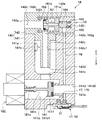
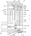
[統合弁14の構成]
ここで、統合弁14の詳細構成について、図4、図5、図6を用いて説明する。なお、図4、図5、図6に示す上下の各矢印は、統合弁14を車両用空調装置1に搭載した状態における上下方向を示している。
[Structure of integrated valve 14]
Here, the detailed configuration of the
統合弁14は、外殻を形成するとともに、内部に開閉部材16および液側弁体181等を収容するボデー140を有している。ボデー140は、アルムニウム合金等の金属材料で構成されている。ボデー140は、下方側に配置されるロワーボデー141と、ロワーボデー141の上方側に取付固定されるアッパーボデー142とで構成されている。
The
ロワーボデー141は、略直方体のブロック体で形成され、その外周側壁面に高段側膨張弁13から流出した冷媒を内部へ流入させる冷媒流入口141aが形成されている。冷媒流入口141aは、ロワーボデー141の内部に形成された気液分離空間141bに連通している。この気液分離空間141bは、その軸線方向が上下方向に延びる略円柱状に形成されている。
The
ロワーボデー141には、気液分離空間141bで分離された液相冷媒を液冷媒通路141d側へ流出させる流出孔141cが形成されている。液冷媒通路141dは、気液分離空間141bの下方側に配置されて、気液分離空間141bにて分離された液相冷媒を統合弁14の外部へ流出させる液流出口141e側へ導く冷媒通路である。
The
また、ロワーボデー141における液冷媒通路141dの途中には、後述する液側弁体181が接離する弁座部141fが形成されている。液冷媒通路141dの内部には、弁座部141fと接離して液冷媒通路141dを開閉する液側弁体181、および液側弁体181に液冷媒通路141dを閉じる向きへの荷重をかけるコイルバネからなるスプリング181a等が収容されている。
Further, in the middle of the liquid
液側弁体181は、シャフト181cを介してソレノイドアクチュエータ182(以下、単にソレノイドとも呼ぶ。)に連結されている。ソレノイド182は、電力を供給することによって電磁力を発生させて可動部を変位させる電磁機構であって、制御装置40から出力される制御電圧によって、その作動が制御される。ソレノイド182は、液側弁体181を駆動する駆動部材を構成する。
The liquid
例えば、制御装置40がソレノイド182に電力を供給すると、図5に示すように、液側弁体181が変位して液冷媒通路141dが開放される。また、例えば、制御装置40がソレノイド182への電力供給を停止すると、図6に示すように、液側弁体181によって液冷媒通路141dが閉鎖される。
For example, when the
ロワーボデー141には、弁座部141fの内部に形成される冷媒通路に対して並列的に、減圧部17が設けられている。減圧部17は、液側弁体181が液冷媒通路141dを閉じた際に、気液分離空間141bにて分離された液相冷媒を減圧させて液流出口141e側へ流出させるものである。
The
減圧部17は、絞り開度が固定された固定絞り170と、減圧部17の絞り開度を調整変更するためのマイクロバルブX1を含むバルブモジュールX0によって構成されている。固定絞り170は、液冷媒通路141dのうち弁座部141fの上流側となる液上流通路141d1と弁座部141fの下流側となる液下流通路141d2とを連通させる。固定絞り170としては、ノズルあるいはオリフィスを採用できる。なお、バルブモジュールX0の詳細については後述する。
The
このように構成される統合弁14は、液側弁体181による液冷媒通路141dの開閉により、気液分離空間141bにて分離された液相冷媒を減圧する絞り状態、および気液分離空間141bを通過した冷媒を減圧しない全開状態に切替可能となっている。
The
続いて、アッパーボデー142は、略直方体のブロック体で形成され、気液分離空間141bの上方側を覆っている。アッパーボデー142には、圧縮機11の中間圧ポート11bに気相冷媒を流出させるガス流出口142aが形成されている。アッパーボデー142は、気液分離空間141bにて分離された気相冷媒をガス流出口142a側へ導くガス冷媒通路142bが形成されている。ガス冷媒通路142bは、ガス流出口142aに向かって水平に延びている。
Subsequently, the
アッパーボデー142は、気液分離空間141bと同軸上に配置される丸管状のパイプ部142cが設けられている。パイプ部142cの下方端部には、気液分離空間141bにて分離された気相冷媒を気液分離空間141bから流出させる冷媒流出部142dが開口している。パイプ部142cの内側には、冷媒流出部142dから流出する冷媒をガス冷媒通路142bに導くパイプ内通路142c1が形成されている。
The
ガス冷媒通路142bには、後述する主弁部材161の一端部が接離する主弁座部142fが形成されている。ガス冷媒通路142bには、ガス流出口142aとは反対側に位置する部位に、ガス冷媒通路142bを開閉する開閉部材16が収容されている。
The
ここで、本実施形態では、ガス冷媒通路142bのうち、主弁座部142fの上流側をガス上流通路142gとし、主弁座部142fの下流側をガス下流通路142hとする。
Here, in the present embodiment, of the
開閉部材16は、主弁部材161、主弾性部材162、副弁部材164、副弾性部材165を備え、副弁部材164の作動により、主弁部材161に作用する圧力を変化させることによって、主弁部材161を変位させるパイロット式の弁機構で構成されている。
The opening / closing
主弁部材161は、シール部材161dが設けられた一端部が主弁座部142fに接触する位置と、主弁座部142fから離間する位置との間で変位することで、ガス冷媒通路142bを開閉する。
The
主弁部材161は、主弁座部142fに接離する一端部が、ガス冷媒通路142bを開く方向に作用する冷媒圧力を受ける受圧面になっている。また、主弁部材161は、主弁座部142fに接離する一端部の反対側の他端部に胴体部161aを有する。この胴体部161aは、ガス上流通路142gとガス上流通路142gの圧力が導入される背圧室142eとを分離するための部材である。なお、胴体部161aは、外径がガス上流通路142gの内径よりも僅かに小さい円柱状に形成されており、ガス上流通路142gの内側壁面に摺動可能になっている。
One end of the
主弁部材161には、ガス下流通路142hと背圧室142eとを連通させる連通路161bが形成されている。なお、連通路161bにおける背圧室142e側の開口部は、副弁部材164により開閉されるパイロット孔を構成している。
The
ガス上流通路142gには、主弁部材161に対してガス冷媒通路142bを開く方向に荷重をかけるコイルバネ等で構成される主弾性部材162が収容されている。背圧室142eには、主弁部材161の変位を規制する規制部材163、および主弁部材161に形成された連通路161bを開閉する副弁部材164が配置されている。
The gas
規制部材163は、ガス冷媒通路142bの内径に適合する外径を有する有底の筒状部材である。規制部材163は、主弁部材161の変位を規制するストッパとしての機能以外に、アッパーボデー142のうちガス流出口142aとは反対側の開口を閉塞する閉塞部材として機能する。
The regulating
副弁部材164は、規制部材163の内側壁面に摺動可能に支持されており、主弁部材161に形成された連通路161bの開口部を閉鎖する閉鎖位置と、当該開口部を開放する開放位置との間で変位することで、連通路161bを開閉する。
The
副弁部材164は、連通路161bに対向する側の一端部が円錐状に形成されている。そして、副弁部材164は、連通路161bに対向する一端部が連通路161bを開く方向に背圧室142eの圧力を受けるように構成されている。つまり、副弁部材164は、その一端部に連通路161bを開く方向に背圧室142eの圧力を受ける受圧面を有する。
The
副弁部材164は、円錐状に形成された一端部の反対側の他端部が、連通路161bを閉じる方向に、後述の圧力室142iの圧力を受けるように構成されている。つまり、副弁部材164は、その他端部に連通路161bを閉じる方向に圧力室142iの圧力を受ける受圧面を有する。
The
ここで、圧力室142iは、副弁部材164の他端部と規制部材163の内側壁面との間に形成される空間である。圧力室142iは、減圧部17の冷媒流れ下流側の冷媒通路に連通する圧力導入通路19に接続されており、この圧力導入通路19を介して減圧部17の冷媒流れ下流側の圧力が導入される。圧力室142iには、副弁部材164に対して、連通路161bを閉じる方向に荷重をかけるコイルバネ等で構成される副弾性部材165が収容されている。
Here, the
このように構成される開閉部材16は、副弁部材164が連通路161bの開口部から離間すると、背圧室142eとガス下流通路142hとが連通し、主弁部材161の前後に作用する圧力に差がなくなることで、主弁部材161が開弁方向に変位する。この場合、図6に示すように、開閉部材16がガス冷媒通路142bを開いた状態になる。なお、副弁部材164は、減圧部17の前後で圧力差が生じている場合に、連通路161bの開口部から離間する位置に変位する。
In the opening / closing
一方、副弁部材164が連通路161bの開口部に当接すると、背圧室142eとガス下流通路142hとの連通が遮断され、主弁部材161の前後に作用する圧力差によって、主弁部材161が閉弁方向に変位する。この場合、図5に示すように、開閉部材16がガス冷媒通路142bを閉じた状態になる。なお、副弁部材164は、減圧部17の前後で圧力差が殆ど生じていない場合に、連通路161bの開口部に接する位置に変位する。
On the other hand, when the
[バルブモジュールX0の構成]
ここで、減圧部17を構成するバルブモジュールX0について図7〜図14を参照して説明する。バルブモジュールX0は、図7に示すように、ロワーボデー141に対して一体的に構成されている。ロワーボデー141は、マイクロバルブX1の取付対象となる被取付対象物を構成している。
[Valve module X0 configuration]
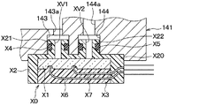
Here, the valve module X0 constituting the
ロワーボデー141の底面には、後述する第1突出部X21および第2突出部X22が嵌め合わされる第1凹部143および第2凹部144が形成されている。第1凹部143の底部には、第1凹部143を液上流通路141d1に連通させる貫通孔143aが形成されている。また、第2凹部144の底部には、第2凹部144を液下流通路141d2に連通させる貫通孔144aが形成されている。
On the bottom surface of the
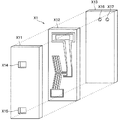
バルブモジュールX0は、マイクロバルブX1、バルブケーシングX2、封止部材X3、2つのOリングX4、X5、2本の電気配線X6、X7を有している。 The valve module X0 has a microvalve X1, a valve casing X2, a sealing member X3, two O-rings X4, X5, and two electrical wirings X6, X7.
マイクロバルブX1は、板形状の弁部品であり、主として半導体チップによって構成されている。マイクロバルブX1は、半導体チップ以外の部品を有していてもいなくてもよい。したがって、マイクロバルブX1を小型に構成できる。マイクロバルブX1の厚さ方向の長さは例えば2mmであり、厚さ方向に直交する長手方向の長さは例えば10mmであり、長手方向にも厚さ方向にも直交する短手方向の長さは例えば5mmであるが、これに限定されない。マイクロバルブX1への通電、非通電が切り替わることで、開閉が切り替わる。具体的には、マイクロバルブX1は、通電時に開弁し、非通電時に閉弁する常閉弁である。 The microvalve X1 is a plate-shaped valve component, and is mainly composed of a semiconductor chip. The microvalve X1 may or may not have parts other than the semiconductor chip. Therefore, the micro valve X1 can be configured in a small size. The length of the microvalve X1 in the thickness direction is, for example, 2 mm, the length in the longitudinal direction orthogonal to the thickness direction is, for example, 10 mm, and the length in the lateral direction orthogonal to both the longitudinal direction and the thickness direction. Is, for example, 5 mm, but is not limited thereto. Opening and closing is switched by switching between energization and non-energization of the micro valve X1. Specifically, the micro valve X1 is a normally closed valve that opens when energized and closes when not energized.
電気配線X6、X7は、マイクロバルブX1の表裏にある2つの板面のうち、バルブケーシングX2とは反対側の面から伸びて、封止部材X3、バルブケーシングX2内を通過して、バルブモジュールX0の外部にある電源に接続される。これにより、電気配線X6、X7を通して、電源からマイクロバルブX1に電力が供給される。 The electrical wirings X6 and X7 extend from the surface of the two plates on the front and back of the microvalve X1 opposite to the valve casing X2, pass through the sealing member X3 and the valve casing X2, and pass through the valve module. It is connected to a power supply outside X0. As a result, power is supplied from the power source to the micro valve X1 through the electric wirings X6 and X7.
バルブケーシングX2は、マイクロバルブX1を収容する樹脂製のケーシングである。バルブケーシングX2は、ポリフェニレンサルファイドを主成分として樹脂成形によって形成されている。バルブケーシングX2は、線膨張係数が、マイクロバルブX1の線膨張係数とロワーボデー141の線膨張係数の間の値となるように構成されている。なお、バルブケーシングX2は、マイクロバルブX1をロワーボデー141に対して取り付けるための部品取付部を構成している。
The valve casing X2 is a resin casing that houses the microvalve X1. The valve casing X2 is formed by resin molding containing polyphenylene sulfide as a main component. The valve casing X2 is configured such that the coefficient of linear expansion is a value between the coefficient of linear expansion of the microvalve X1 and the coefficient of linear expansion of the
バルブケーシングX2は、一方側に底壁を有し、他方側が開放された凹形状の箱体である。バルブケーシングX2の底壁は、マイクロバルブX1とロワーボデー141とが直接接しないように、マイクロバルブX1とロワーボデー141の間に介在する。そして、この底壁の一方側の面がロワーボデー141に接触して固定され、他方側の面がマイクロバルブX1の2つの板面のうち一方に接触して固定される。このようになっていることで、マイクロバルブX1とロワーボデー141の線膨張係数の違いをバルブケーシングX2が吸収できる。これは、バルブケーシングX2の線膨張係数が、マイクロバルブX1の線膨張係数とロワーボデー141の線膨張係数の間の値となっているからである。
The valve casing X2 is a concave box body having a bottom wall on one side and an open side on the other side. The bottom wall of the valve casing X2 is interposed between the microvalve X1 and the
また、バルブケーシングX2の底壁は、マイクロバルブX1に対向する板形状のベース部X20と、マイクロバルブX1から離れる方向に当該ベース部X20から突出する柱形状の第1突出部X21、第2突出部X22を有する。 Further, the bottom wall of the valve casing X2 has a plate-shaped base portion X20 facing the microvalve X1 and a pillar-shaped first protruding portion X21 and a second protruding portion X21 protruding from the base portion X20 in a direction away from the microvalve X1. It has a portion X22.
第1突出部X21、第2突出部X22は、ロワーボデー141に形成された凹みに嵌め込まれている。第1突出部X21には、マイクロバルブX1側端から第1凹部143の底部側端まで貫通する第1連通孔XV1が形成されている。第2突出部X22には、マイクロバルブX1側端から第2凹部144の底部側端まで貫通する第2連通孔XV2が形成されている。
The first protruding portion X21 and the second protruding portion X22 are fitted in the recess formed in the
封止部材X3は、バルブケーシングX2の開放された上記他方側を封止するエポキシ樹脂製の部材である。封止部材X3は、マイクロバルブX1の表裏にある2つの板面のうち、バルブケーシングX2の底壁側とは反対側の板面を、覆う。また、封止部材X3は、電気配線X6、X7を覆うことで、電気配線X6、X7の防水および絶縁を実現する。封止部材X3は樹脂ポッティング等によって形成される。 The sealing member X3 is a member made of epoxy resin that seals the other open side of the valve casing X2. The sealing member X3 covers the plate surface of the two plate surfaces on the front and back sides of the micro valve X1 on the side opposite to the bottom wall side of the valve casing X2. Further, the sealing member X3 covers the electric wirings X6 and X7 to realize waterproofing and insulation of the electric wirings X6 and X7. The sealing member X3 is formed by resin potting or the like.
OリングX4は、第1突出部X21の外周に取り付けられ、ロワーボデー141と第1突出部X21の間を封止することで、統合弁14の外部への冷媒の漏出を抑制する。OリングX5は、第2突出部X22の外周に取り付けられ、ロワーボデー141と第2突出部X22の間を封止することで、統合弁14の外部への冷媒の漏出を抑制する。
The O-ring X4 is attached to the outer periphery of the first protruding portion X21 and seals between the
[マイクロバルブX1の構成]
ここで、マイクロバルブX1の構成について更に説明する。マイクロバルブX1は、図8、図9に示すように、いずれも半導体である第1外層X11、中間層X12、第2外層X13を備えたMEMSである。MEMSは、Micro Electro Mechanical Systemsの略称である。第1外層X11、中間層X12、第2外層X13は、それぞれが同じ外形を有する長方形の板形状の部材であり、第1外層X11、中間層X12、第2外層X13の順に積層されている。第1外層X11、中間層X12、第2外層X13のうち、第2外層X13が、バルブケーシングX2の底壁に最も近い側に配置される。後述する第1外層X11、中間層X12、第2外層X13の構造は、化学的エッチング等の半導体製造プロセスによって形成される。
[Structure of micro valve X1]
Here, the configuration of the micro valve X1 will be further described. As shown in FIGS. 8 and 9, the microvalve X1 is a MEMS having a first outer layer X11, an intermediate layer X12, and a second outer layer X13, all of which are semiconductors. MEMS is an abbreviation for Micro Electro Mechanical Systems. The first outer layer X11, the intermediate layer X12, and the second outer layer X13 are rectangular plate-shaped members having the same outer shape, and the first outer layer X11, the intermediate layer X12, and the second outer layer X13 are laminated in this order. Of the first outer layer X11, the intermediate layer X12, and the second outer layer X13, the second outer layer X13 is arranged on the side closest to the bottom wall of the valve casing X2. The structures of the first outer layer X11, the intermediate layer X12, and the second outer layer X13, which will be described later, are formed by a semiconductor manufacturing process such as chemical etching.
第1外層X11は、表面に非導電性の酸化膜のある導電性の半導体部材である。第1外層X11には、図8に示すように、表裏に貫通する2つの貫通孔X14、X15が形成されている。この貫通孔X14、X15に、それぞれ、電気配線X6、X7のマイクロバルブX1側端が挿入される。 The first outer layer X11 is a conductive semiconductor member having a non-conductive oxide film on its surface. As shown in FIG. 8, two through holes X14 and X15 penetrating the front and back are formed in the first outer layer X11. The microvalve X1 side ends of the electrical wirings X6 and X7 are inserted into the through holes X14 and X15, respectively.
第2外層X13は、表面に非導電性の酸化膜のある導電性の半導体部材である。第2外層X13には、図8、図10、図11に示すように、表裏に貫通する第1冷媒孔X16、第2冷媒孔X17が形成されている。図11に示すように、第1冷媒孔X16はバルブケーシングX2の第1連通孔XV1に連通し、第2冷媒孔X17はバルブケーシングX2の第2連通孔XV2に連通する。第1冷媒孔X16、第2冷媒孔X17の各々の水力直径は、例えば0.1mm以上かつ3mm以下であるが、これに限定されない。第1冷媒孔X16、第2冷媒孔X17は、それぞれ、第1流体孔、第2流体孔である。 The second outer layer X13 is a conductive semiconductor member having a non-conductive oxide film on its surface. As shown in FIGS. 8, 10, and 11, the second outer layer X13 is formed with a first refrigerant hole X16 and a second refrigerant hole X17 penetrating the front and back surfaces. As shown in FIG. 11, the first refrigerant hole X16 communicates with the first communication hole XV1 of the valve casing X2, and the second refrigerant hole X17 communicates with the second communication hole XV2 of the valve casing X2. The hydraulic diameters of the first refrigerant holes X16 and the second refrigerant holes X17 are, for example, 0.1 mm or more and 3 mm or less, but are not limited thereto. The first refrigerant hole X16 and the second refrigerant hole X17 are a first fluid hole and a second fluid hole, respectively.
中間層X12は、導電性の半導体部材であり、第1外層X11と第2外層X13に挟まれている。中間層X12は、第1外層X11の酸化膜と第2外層X13の酸化膜に接触するので、第1外層X11と第2外層X13とも電気的に非導通である。中間層X12は、図10に示すように、第1固定部X121、第2固定部X122、複数本の第1リブX123、複数本の第2リブX124、スパインX125、アームX126、梁X127、可動部X128を有している。 The intermediate layer X12 is a conductive semiconductor member, and is sandwiched between the first outer layer X11 and the second outer layer X13. Since the intermediate layer X12 comes into contact with the oxide film of the first outer layer X11 and the oxide film of the second outer layer X13, both the first outer layer X11 and the second outer layer X13 are electrically non-conducting. As shown in FIG. 10, the intermediate layer X12 has a first fixed portion X121, a second fixed portion X122, a plurality of first ribs X123, a plurality of second ribs X124, a spine X125, an arm X126, a beam X127, and a movable layer. It has a part X128.
第1固定部X121は、第1外層X11、第2外層X13に対して固定された部材である。第1固定部X121は、第2固定部X122、第1リブX123、第2リブX124、スパインX125、アームX126、梁X127、可動部X128を同じ1つの流体室X19内に囲むように形成されている。流体室X19は、第1固定部X121、第1外層X11、第2外層X13によって囲まれた室である。流体室X19は、液冷媒通路141dを通過する冷媒の少なくとも一部が流通する。第1固定部X121、第1外層X11、第2外層X13は、全体として基部に対応する。なお、電気配線X6、X7は複数の第1リブX123および複数の第2リブX124の温度を変化させて変位させるための電気配線である。
The first fixing portion X121 is a member fixed to the first outer layer X11 and the second outer layer X13. The first fixed portion X121 is formed so as to surround the second fixed portion X122, the first rib X123, the second rib X124, the spine X125, the arm X126, the beam X127, and the movable portion X128 in the same fluid chamber X19. There is. The fluid chamber X19 is a chamber surrounded by a first fixed portion X121, a first outer layer X11, and a second outer layer X13. At least a part of the refrigerant passing through the liquid
第1固定部X121の第1外層X11および第2外層X13に対する固定は、冷媒がこの流体室X19から第1冷媒孔X16、第2冷媒孔X17以外を通ってマイクロバルブX1から漏出することを抑制するような形態で、行われている。 The fixing of the first fixing portion X121 to the first outer layer X11 and the second outer layer X13 suppresses the leakage of the refrigerant from the fluid chamber X19 through the fluid chamber X19 other than the first refrigerant hole X16 and the second refrigerant hole X17. It is done in such a form.
第2固定部X122は、第1外層X11、第2外層X13に対して固定される。第2固定部X122は、第1固定部X121に取り囲まれると共に、第1固定部X121から離れて配置される。 The second fixing portion X122 is fixed to the first outer layer X11 and the second outer layer X13. The second fixed portion X122 is surrounded by the first fixed portion X121 and is arranged away from the first fixed portion X121.
複数本の第1リブX123、複数本の第2リブX124、スパインX125、アームX126、梁X127、可動部X128は、第1外層X11、第2外層X13に対して固定されておらず、第1外層X11、第2外層X13に対して変位可能である。 The plurality of first ribs X123, the plurality of second ribs X124, the spine X125, the arm X126, the beam X127, and the movable portion X128 are not fixed to the first outer layer X11 and the second outer layer X13, and are the first. It is displaceable with respect to the outer layer X11 and the second outer layer X13.
スパインX125は、中間層X12の矩形形状の短手方向に伸びる細長い棒形状を有している。スパインX125の長手方向の一端は、梁X127に接続されている。 The spine X125 has an elongated rod shape extending in the lateral direction in the rectangular shape of the intermediate layer X12. One end of the spine X125 in the longitudinal direction is connected to the beam X127.
複数本の第1リブX123は、スパインX125の長手方向に直交する方向におけるスパインX125の一方側に配置される。そして、複数本の第1リブX123は、スパインX125の長手方向に並んでいる。各第1リブX123は、細長い棒形状を有しており、温度に応じて伸縮可能となっている。 The plurality of first ribs X123 are arranged on one side of the spine X125 in a direction orthogonal to the longitudinal direction of the spine X125. The plurality of first ribs X123 are arranged in the longitudinal direction of the spine X125. Each first rib X123 has an elongated rod shape and can be expanded and contracted according to the temperature.
各第1リブX123は、その長手方向の一端で第1固定部X121に接続され、他端でスパインX125に接続される。そして、各第1リブX123は、第1固定部X121側からスパインX125側に近付くほど、スパインX125の長手方向の梁X127側に向けてオフセットされるよう、スパインX125に対して斜行している。そして、複数の第1リブX123は、互いに対して平行に伸びている。 Each first rib X123 is connected to the first fixing portion X121 at one end in the longitudinal direction thereof and to the spine X125 at the other end. Each of the first ribs X123 is skewed with respect to the spine X125 so as to approach the spine X125 side from the first fixing portion X121 side so as to be offset toward the beam X127 side in the longitudinal direction of the spine X125. .. The plurality of first ribs X123 extend in parallel with each other.
複数本の第2リブX124は、スパインX125の長手方向に直交する方向におけるスパインX125の他方側に配置される。そして、複数本の第2リブX124は、スパインX125の長手方向に並んでいる。各第2リブX124は、細長い棒形状を有しており、温度に応じて伸縮可能となっている。 The plurality of second ribs X124 are arranged on the other side of the spine X125 in a direction orthogonal to the longitudinal direction of the spine X125. The plurality of second ribs X124 are arranged in the longitudinal direction of the spine X125. Each second rib X124 has an elongated rod shape and can be expanded and contracted according to the temperature.
各第2リブX124は、その長手方向の一端で第2固定部X122に接続され、他端でスパインX125に接続される。そして、各第2リブX124は、第2固定部X122側からスパインX125側に近付くほど、スパインX125の長手方向の梁X127側に向けてオフセットされるよう、スパインX125に対して斜行している。そして、複数の第2リブX124は、互いに対して平行に伸びている。複数本の第1リブX123、複数本の第2リブX124、スパインX125は、全体として、駆動部に対応する。 Each second rib X124 is connected to the second fixing portion X122 at one end in the longitudinal direction thereof and to the spine X125 at the other end. Each of the second ribs X124 is skewed with respect to the spine X125 so as to approach the spine X125 side from the second fixed portion X122 side so as to be offset toward the beam X127 side in the longitudinal direction of the spine X125. .. The plurality of second ribs X124 extend in parallel with each other. The plurality of first ribs X123, the plurality of second ribs X124, and the spine X125 correspond to the drive unit as a whole.
アームX126は、スパインX125と非直交かつ平行に伸びる細長い棒形状を有している。アームX126の長手方向の一端は梁X127に接続されており、他端は第1固定部X121に接続されている。 The arm X126 has an elongated rod shape extending non-orthogonally and parallel to the spine X125. One end of the arm X126 in the longitudinal direction is connected to the beam X127, and the other end is connected to the first fixing portion X121.
梁X127は、スパインX125およびアームX126に対して約90°で交差する方向に伸びる細長い棒形状を有している。梁X127の一端は、可動部X128に接続されている。アームX126と梁X127は、全体として、増幅部に対応する。 The beam X127 has an elongated rod shape extending in a direction intersecting the spine X125 and the arm X126 at about 90 °. One end of the beam X127 is connected to the movable portion X128. The arm X126 and the beam X127 correspond to the amplification portion as a whole.
アームX126と梁X127の接続位置XP1、スパインX125と梁X127の接続位置XP2、梁X127と可動部X128の接続位置XP3は、梁X127の長手方向に沿って、この順に並んでいる。そして、第1固定部X121とアームX126との接続点をヒンジXP0とすると、中間層X12の板面に平行な面内におけるヒンジXP0から接続位置XP2までの直線距離よりも、ヒンジXP0から接続位置XP3までの直線距離の方が、長い。 The connection position XP1 of the arm X126 and the beam X127, the connection position XP2 of the spine X125 and the beam X127, and the connection position XP3 of the beam X127 and the movable portion X128 are arranged in this order along the longitudinal direction of the beam X127. Then, assuming that the connection point between the first fixing portion X121 and the arm X126 is the hinge XP0, the connection position from the hinge XP0 is more than the linear distance from the hinge XP0 to the connection position XP2 in the plane parallel to the plate surface of the intermediate layer X12. The straight line distance to XP3 is longer.
可動部X128は、流体室X19における冷媒の圧力を調整するものである。可動部X128は、その外形が、梁X127の長手方向に対して概ね90°の方向に伸びる矩形形状を有している。この可動部X128は、流体室X19内において梁X127と一体に動くことができる。そして、可動部X128は、そのように動くことで、ある位置にいるときには第1冷媒孔X16と第2冷媒孔X17とを流体室X19を介して連通させ、また別の位置にいるときには第1冷媒孔X16と第2冷媒孔X17とを流体室X19内において遮断する。可動部X128は、中間層X12の表裏に貫通する貫通孔X120を囲む枠形状となっている。したがって、貫通孔X120も、可動部X128と一体的に移動する。貫通孔X120は、流体室X19の一部である。 The movable portion X128 adjusts the pressure of the refrigerant in the fluid chamber X19. The movable portion X128 has a rectangular shape whose outer shape extends in a direction of approximately 90 ° with respect to the longitudinal direction of the beam X127. The movable portion X128 can move integrally with the beam X127 in the fluid chamber X19. Then, by moving in this way, the movable portion X128 communicates the first refrigerant hole X16 and the second refrigerant hole X17 with each other via the fluid chamber X19 when it is in a certain position, and when it is in another position, it is the first. The refrigerant hole X16 and the second refrigerant hole X17 are shut off in the fluid chamber X19. The movable portion X128 has a frame shape surrounding the through hole X120 penetrating the front and back of the intermediate layer X12. Therefore, the through hole X120 also moves integrally with the movable portion X128. The through hole X120 is a part of the fluid chamber X19.
また、第1固定部X121のうち、複数の第1リブX123と接続する部分の近傍の第1印加点X129には、図8に示した第1外層X11の貫通孔X14を通った電気配線X6のマイクロバルブX1側端が接続される。また、第2固定部X122の第2印加点X130には、図8に示した第1外層X11の貫通孔X15を通った電気配線X7のマイクロバルブX1側端が接続される。 Further, at the first application point X129 in the vicinity of the portion of the first fixed portion X121 connected to the plurality of first ribs X123, the electric wiring X6 passing through the through hole X14 of the first outer layer X11 shown in FIG. The microvalve X1 side end of is connected. Further, the microvalve X1 side end of the electric wiring X7 passing through the through hole X15 of the first outer layer X11 shown in FIG. 8 is connected to the second application point X130 of the second fixing portion X122.
[バルブモジュールX0の作動]
ここで、バルブモジュールX0の作動について説明する。マイクロバルブX1への通電時は、電気配線X6、X7から第1印加点X129、第2印加点X130の間に電圧が印加される。すると、複数の第1リブX123、複数の第2リブX124を電流が流れる。この電流によって、複数の第1リブX123、複数の第2リブX124が発熱してそれらの温度が上昇する。その結果、複数の第1リブX123、複数の第2リブX124の各々が、その長手方向に膨張する。
[Operation of valve module X0]
Here, the operation of the valve module X0 will be described. When the microvalve X1 is energized, a voltage is applied between the electrical wirings X6 and X7 to the first application point X129 and the second application point X130. Then, a current flows through the plurality of first ribs X123 and the plurality of second ribs X124. Due to this current, the plurality of first ribs X123 and the plurality of second ribs X124 generate heat and their temperatures rise. As a result, each of the plurality of first ribs X123 and the plurality of second ribs X124 expands in the longitudinal direction thereof.
このような、温度上昇に伴う熱的な膨張の結果、複数の第1リブX123、複数の第2リブX124は、スパインX125を接続位置XP2側に付勢する。付勢されたスパインX125は、接続位置XP2において、梁X127を押す。このように、接続位置XP2は付勢位置に対応する。 As a result of such thermal expansion due to the temperature rise, the plurality of first ribs X123 and the plurality of second ribs X124 urge the spine X125 toward the connection position XP2. The urged spine X125 pushes the beam X127 at the connection position XP2. In this way, the connection position XP2 corresponds to the urging position.
そして、梁X127とアームX126から成る部材は、ヒンジXP0を支点として、接続位置XP2を力点として、一体に姿勢を変える。その結果、梁X127のアームX126とは反対側の端部に接続された可動部X128も、その長手方向の、スパインX125が梁X127を押す側に、移動する。その移動の結果、可動部X128は、図12、図13に示すように、移動方向の先端が第1固定部X121に当接する位置に到達する。以下、可動部X128のこの位置を通電時位置という。 Then, the member composed of the beam X127 and the arm X126 integrally changes its posture with the hinge XP0 as a fulcrum and the connection position XP2 as a power point. As a result, the movable portion X128 connected to the end of the beam X127 opposite to the arm X126 also moves in the longitudinal direction to the side where the spine X125 pushes the beam X127. As a result of the movement, the movable portion X128 reaches a position where the tip in the moving direction abuts on the first fixed portion X121, as shown in FIGS. 12 and 13. Hereinafter, this position of the movable portion X128 is referred to as an energized position.
このように、梁X127およびアームX126は、ヒンジXP0を支点とし、接続位置XP2を力点とし、接続位置XP3を作用点とする梃子として機能する。上述の通り、中間層X12の板面に平行な面内におけるヒンジXP0から接続位置XP2までの直線距離よりも、ヒンジXP0から接続位置XP3までの直線距離の方が、長い。したがって、力点である接続位置XP2の移動量よりも、作用点である接続位置XP3の移動量の方が大きくなる。したがって、熱的な膨張による変位量が、梃子によって増幅されて可動部X128に伝わる。 As described above, the beam X127 and the arm X126 function as a lever having the hinge XP0 as a fulcrum, the connection position XP2 as a force point, and the connection position XP3 as an action point. As described above, the linear distance from the hinge XP0 to the connection position XP3 is longer than the linear distance from the hinge XP0 to the connection position XP2 in the plane parallel to the plate surface of the intermediate layer X12. Therefore, the amount of movement of the connection position XP3, which is the point of action, is larger than the amount of movement of the connection position XP2, which is the point of effort. Therefore, the amount of displacement due to thermal expansion is amplified by the lever and transmitted to the movable portion X128.
図12、図13に示すように、可動部X128が通電時位置にある場合、貫通孔X120が中間層X12の板面に直交する方向に第1冷媒孔X16、第2冷媒孔X17と重なる。その場合、第1冷媒孔X16と第2冷媒孔X17とが流体室X19の一部である貫通孔X120を介して連通する。この結果、第1連通孔XV1と第2連通孔XV2との間で、第1冷媒孔X16、貫通孔X120、第2冷媒孔X17を介した、冷媒の流通が可能となる。つまり、マイクロバルブX1が開弁する。このように、第1冷媒孔X16、貫通孔X120、第2冷媒孔X17は、マイクロバルブX1の開弁時にマイクロバルブX1内において冷媒が流通する冷媒流路である。 As shown in FIGS. 12 and 13, when the movable portion X128 is in the energized position, the through hole X120 overlaps with the first refrigerant hole X16 and the second refrigerant hole X17 in the direction orthogonal to the plate surface of the intermediate layer X12. In that case, the first refrigerant hole X16 and the second refrigerant hole X17 communicate with each other through the through hole X120 which is a part of the fluid chamber X19. As a result, the refrigerant can flow between the first communication hole XV1 and the second communication hole XV2 through the first refrigerant hole X16, the through hole X120, and the second refrigerant hole X17. That is, the micro valve X1 opens. As described above, the first refrigerant hole X16, the through hole X120, and the second refrigerant hole X17 are the refrigerant flow paths through which the refrigerant flows in the micro valve X1 when the micro valve X1 is opened.
このときの、マイクロバルブX1における冷媒の流路は、Uターン構造を有している。具体的には、冷媒は、マイクロバルブX1の一方側の面からマイクロバルブX1内に流入し、マイクロバルブX1内を通って、マイクロバルブX1の同じ側の面からマイクロバルブX1外に流出する。そして同様にバルブモジュールX0における冷媒の流路も、Uターン構造を有している。具体的には、冷媒は、バルブモジュールX0の一方側の面からバルブモジュールX0内に流入し、バルブモジュールX0内を通って、バルブモジュールX0の同じ側の面からバルブモジュールX0外に流出する。なお、中間層X12の板面に直交する方向は、第1外層X11、中間層X12、第2外層X13の積層方向である。 At this time, the flow path of the refrigerant in the micro valve X1 has a U-turn structure. Specifically, the refrigerant flows into the microvalve X1 from one surface of the microvalve X1, passes through the microvalve X1, and flows out of the microvalve X1 from the same side surface of the microvalve X1. Similarly, the flow path of the refrigerant in the valve module X0 also has a U-turn structure. Specifically, the refrigerant flows into the valve module X0 from one surface of the valve module X0, passes through the inside of the valve module X0, and flows out of the valve module X0 from the same side surface of the valve module X0. The direction orthogonal to the plate surface of the intermediate layer X12 is the stacking direction of the first outer layer X11, the intermediate layer X12, and the second outer layer X13.
また、マイクロバルブX1への非通電時は、電気配線X6、X7から第1印加点X129、第2印加点X130への電圧印加が停止される。すると、複数の第1リブX123、複数の第2リブX124を電流が流れなくなり、複数の第1リブX123、複数の第2リブX124の温度が低下する。その結果、複数の第1リブX123、複数の第2リブX124の各々が、その長手方向に収縮する。 Further, when the micro valve X1 is not energized, the voltage application from the electric wirings X6 and X7 to the first application point X129 and the second application point X130 is stopped. Then, the current stops flowing through the plurality of first ribs X123 and the plurality of second ribs X124, and the temperatures of the plurality of first ribs X123 and the plurality of second ribs X124 decrease. As a result, each of the plurality of first ribs X123 and the plurality of second ribs X124 contracts in the longitudinal direction thereof.
このような、温度低下を伴う熱的な収縮の結果、複数の第1リブX123、複数の第2リブX124は、スパインX125を接続位置XP2とは反対側に付勢する。付勢されたスパインX125は、接続位置XP2において、梁X127を引っ張る。その結果、梁X127とアームX126から成る部材は、ヒンジXP0を支点として、接続位置XP2を力点として、一体に姿勢を変える。その結果、梁X127のアームX126とは反対側の端部に接続された可動部X128も、その長手方向の、スパインX125が梁X127を引っ張る側に、移動する。その移動の結果、可動部X128は、図10、図11に示すように、第1固定部X121に当接しない位置に到達する。以下、可動部X128のこの位置を非通電時位置という。 As a result of such thermal contraction accompanied by a decrease in temperature, the plurality of first ribs X123 and the plurality of second ribs X124 urge the spine X125 to the side opposite to the connection position XP2. The urged spine X125 pulls the beam X127 at the connection position XP2. As a result, the member including the beam X127 and the arm X126 changes their postures integrally with the hinge XP0 as the fulcrum and the connection position XP2 as the power point. As a result, the movable portion X128 connected to the end of the beam X127 opposite to the arm X126 also moves in the longitudinal direction to the side where the spine X125 pulls the beam X127. As a result of the movement, the movable portion X128 reaches a position where it does not abut on the first fixed portion X121 as shown in FIGS. 10 and 11. Hereinafter, this position of the movable portion X128 is referred to as a non-energized position.
図10、図11に示すように、可動部X128が非通電時位置にある場合、貫通孔X120は、中間層X12の板面に直交する方向に第1冷媒孔X16と重なるが、当該方向に第2冷媒孔X17とは重ならない。第2冷媒孔X17は、中間層X12の板面に直交する方向に可動部X128と重なる。つまり、第2冷媒孔X17は、可動部X128によって塞がれる。したがってこの場合、第1冷媒孔X16と第2冷媒孔X17とが流体室X19内において遮断される。この結果、第1連通孔XV1と第2連通孔XV2との間で、第1冷媒孔X16、第2冷媒孔X17を介した冷媒の流通は阻害される。つまり、マイクロバルブX1が閉弁する。 As shown in FIGS. 10 and 11, when the movable portion X128 is in the non-energized position, the through hole X120 overlaps with the first refrigerant hole X16 in the direction orthogonal to the plate surface of the intermediate layer X12, but in that direction. It does not overlap with the second refrigerant hole X17. The second refrigerant hole X17 overlaps the movable portion X128 in the direction orthogonal to the plate surface of the intermediate layer X12. That is, the second refrigerant hole X17 is closed by the movable portion X128. Therefore, in this case, the first refrigerant hole X16 and the second refrigerant hole X17 are blocked in the fluid chamber X19. As a result, the flow of the refrigerant between the first communication hole XV1 and the second communication hole XV2 through the first refrigerant hole X16 and the second refrigerant hole X17 is hindered. That is, the micro valve X1 is closed.
このように構成される減圧部17は、その流路面積が、マイクロバルブX1への非通電時に固定絞り170の流路面積となり、通電時に固定絞り170の流路面積にバルブモジュールX0の流路面積を加えた大きさとなる。すなわち、減圧部17は、図14に示すように、マイクロバルブX1への非通電時に絞り開度が小開度S1となり、通電時に絞り開度が大開度S2となる。このように、減圧部17は、マイクロバルブX1への通電、非通電を切り替えることで、減圧部17の絞り開度の調整が可能になっている。具体的には、減圧部17は、マイクロバルブX1への通電を停止することで絞り開度を小さくすることができる。
The flow path area of the
図1、図2、図3に戻り、室外熱交換器20は、ボンネット内に配置されて、内部を流通する冷媒と送風ファン21から送風された車室外空気(すなわち、外気)とを熱交換させるものである。この室外熱交換器20は、第1、第2暖房モード時に冷媒を蒸発させて吸熱作用を発揮させる吸熱器として機能し、冷房モード時等に冷媒を放熱させる放熱器として機能する。
Returning to FIGS. 1, 2, and 3, the
室外熱交換器20の冷媒出口側には、低段側膨張弁22の冷媒入口側が接続されている
。低段側膨張弁22は、冷房モード時に室外熱交換器20から流出し、室内蒸発器23へ流入する冷媒を減圧させるものである。低段側膨張弁22の基本的構成は、高段側膨張弁13と同様であり、制御装置40から出力される制御信号によって、その作動が制御される。
The refrigerant inlet side of the lower
低段側膨張弁22の出口側には、室内蒸発器23の冷媒入口側が接続されている。室内蒸発器23は、後述の空調ケース31内のうち、室内凝縮器12の送風空気流れ上流側に配置されている。室内蒸発器23は、冷房モード時および除湿暖房モード時に、冷媒を蒸発させて吸熱作用を発揮させることにより車室内への送風空気を冷却する熱交換器である。
The refrigerant inlet side of the
室内蒸発器23の冷媒出口側には、アキュムレータ24の入口側が接続されている。アキュムレータ24は、その内部に流入した冷媒の気液を分離して余剰冷媒を蓄えるものである。さらに、アキュムレータ24の気相冷媒出口側には、圧縮機11の吸入ポート11aが接続されている。従って、室内蒸発器23は、圧縮機11の吸入ポート11a側へ流出させるように接続されている。
The inlet side of the
さらに、室外熱交換器20の冷媒出口側には、室外熱交換器20から流出した冷媒を低段側膨張弁22および室内蒸発器23を迂回させてアキュムレータ24の入口側へ導く迂回通路25が接続されている。
Further, on the refrigerant outlet side of the
この迂回通路25には、通路開閉弁27が配置されている。この通路開閉弁27は、迂回通路25を開閉する電磁弁であり、制御装置40から出力される制御信号によって、その開閉作動が制御される。
A passage opening / closing
室外熱交換器20から流出した冷媒は、通路開閉弁27が開いている場合に迂回通路25を介してアキュムレータ24へ流入し、通路開閉弁27が閉じている場合に低段側膨張弁22を介して室内蒸発器23へ流入する。このように、通路開閉弁27は、迂回通路25を開閉することによって、冷媒回路を切り替える機能を果たす。したがって、本実施形態の通路開閉弁27は、冷媒回路の切替部を構成している。
The refrigerant flowing out of the
次に、室内空調ユニット30について説明する。室内空調ユニット30は、車室内最前部の計器盤の内側に配置されている。室内空調ユニット30は、車室内に送風される送風空気の空気通路を形成する空調ケース31を有している。この空気通路には送風機32、前述の室内凝縮器12、室内蒸発器23等が収容されている。
Next, the indoor
空調ケース31の空気流れ最上流側には、車室内空気(すなわち、内気)と外気とを切替導入する内外気切替装置33が配置されている。この内外気切替装置33は、空調ケース31内に導入させる内気の風量と外気の風量との風量割合を変化させるものである。
On the most upstream side of the air flow of the
内外気切替装置33の空気流れ下流側には、内外気切替装置33を介して吸入した空気を車室内へ向けて送風する送風機32が配置されている。この送風機32は、ファンを電動モータにて駆動する電動送風機であって、制御装置40から出力される制御電圧によって回転数が制御される。
On the downstream side of the air flow of the inside / outside
送風機32の空気流れ下流側には、前述の室内蒸発器23および室内凝縮器12が、送風空気の流れに対して、室内蒸発器23→室内凝縮器12の順に配置されている。また、空調ケース31内には、室内蒸発器23通過後の送風空気を、室内凝縮器12を迂回して流すバイパス通路35が設けられいる。そして、室内蒸発器23の空気流れ下流側であって、かつ、室内凝縮器12の空気流れ上流側に、エアミックスドア34が配置されている。
On the downstream side of the air flow of the
エアミックスドア34は、室内凝縮器12側を通過する送風空気の風量とバイパス通路35を通過させる風量との風量割合を調整することによって、室内凝縮器12へ流入する送風空気の流量を調整する流量調整手段である。
The
また、室内凝縮器12およびバイパス通路35の空気流れ下流側には、室内凝縮器12にて冷媒と熱交換して加熱された送風空気とバイパス通路35を通過して加熱されていない送風空気が合流する合流空間36が設けられている。このため、エアミックスドア34が、室内凝縮器12を通過させる風量とバイパス通路35を通過させる風量との風量割合を調整することによって、合流空間36内の送風空気の温度が調整される。なお、エアミックスドア34は、制御装置40から出力される制御信号によって作動が制御される。
Further, on the downstream side of the air flow of the
空調ケース31の空気流れ最下流部には、合流空間36にて合流した送風空気を、冷却対象空間である車室内へ吹き出す開口穴が配置されている。具体的には、この開口穴としては、車両前面窓ガラス内側面に向けて空調風を吹き出すデフロスタ開口穴37a、車室内の乗員の上半身に向けて空調風を吹き出すフェイス開口穴37b、乗員の足元に向けて空調風を吹き出すフット開口穴37cが設けられている。
At the most downstream portion of the air flow of the
さらに、デフロスタ開口穴37a、フェイス開口穴37bおよびフット開口穴37cの空気流れ上流側には、それぞれ、デフロスタドア38a、フェイスドア38b、フットドア38cが配置されている。これらのデフロスタドア38a、フェイスドア38bおよびフットドア38cは、制御装置40から出力される制御信号によってその作動が制御される。
Further, a
また、デフロスタ開口穴37a、フェイス開口穴37bおよびフット開口穴37cの空気流れ下流側は、それぞれ空気通路を形成するダクトを介して、車室内に設けられたフェイス吹出口、フット吹出口およびデフロスタ吹出口に接続されている。
Further, the air flow downstream sides of the
次に、本実施形態の電気制御部について説明する。制御装置40は、プロセッサ、メモリ等を含むマイクロコンピュータとその周辺回路から構成される。制御装置40は、メモリ内に記憶された空調制御プログラムに基づいて各種演算、処理を行い、出力側に接続された各種空調制御機器の作動を制御する。
Next, the electric control unit of this embodiment will be described. The
また、制御装置40の入力側には、空調制御用のセンサ群41が接続されている。空調制御用のセンサ群41は、内気センサ、外気センサ、日射センサ、蒸発器温度センサ、吹出空気温度センサ、吐出圧センサ、吐出温度センサ、凝縮器温度センサ、吸入圧センサ、吸入温度センサ等で構成される。
Further, a
さらに、制御装置40の入力側には、車室内前部の計器盤付近に配置された図示しない操作パネルが接続され、この操作パネルに設けられた空調操作スイッチ群42からの操作信号が入力される。空調操作スイッチ群42は、例えば、車両用空調装置1の作動スイッチ、車室内温度を設定する車室内温度設定スイッチ、運転モードを切り替えるモード切替スイッチ等で構成される。
Further, an operation panel (not shown) arranged near the instrument panel in the front part of the vehicle interior is connected to the input side of the
次に、上記構成における車両用空調装置1の作動について説明する。車両用空調装置1は、モード選択スイッチの操作信号に応じて冷房モード、または暖房モードに切り替わる。
Next, the operation of the
(a)冷房モード
冷房モードでは、制御装置40が、高段側膨張弁13を全開状態とし、低段側膨張弁22を全閉状態とし、通路開閉弁27を閉弁状態とする。また、制御装置40は、統合弁14のソレノイド182を通電状態とし、後述するマイクロバルブX1を非通電状態とする。
(A) Cooling mode In the cooling mode, the
これにより、統合弁14は、図5に示すように、液側弁体181が液冷媒通路141dを開き、開閉部材16がガス冷媒通路142bを閉じた状態となる。そして、ヒートポンプサイクル10は、図1の実線矢印に示すように冷媒が流れる冷媒回路に切り替えられる。
As a result, as shown in FIG. 5, the
この冷媒回路の構成で、制御装置40が上述の空調制御用のセンサ群41の検出信号および空調操作スイッチ群42の操作信号等に基づいて、制御装置40の出力側に接続された各種空調制御機器を制御する。
In this refrigerant circuit configuration, the
例えば、制御装置40は、室内凝縮器12の空気通路が閉塞されるようにエアミックスドア34を制御する。これにより、室内蒸発器23通過後の送風空気の全流量がバイパス通路35を通過する。
For example, the
冷房モード時には、圧縮機11の吐出ポート11cから吐出された高圧冷媒が室内凝縮器12へ流入する。この際、エアミックスドア34が室内凝縮器12の空気通路を閉塞しているので、室内凝縮器12へ流入した冷媒は殆ど送風空気へ放熱することなく、室内凝縮器12から流出する。
In the cooling mode, the high-pressure refrigerant discharged from the
室内凝縮器12から流出した冷媒は、高段側膨張弁13が全開状態となっているので、高段側膨張弁13にて殆ど減圧されることなく流出し、統合弁14の冷媒流入口141aから気液分離空間141b内へ流入する。
Since the high-
統合弁14へ流入する冷媒は過熱度を有する気相状態となっているので、統合弁14の気液分離空間141bでは冷媒の気液が分離されることなく、気相冷媒が液冷媒通路141dへ流入する。さらに、液冷媒通路141dへ流入した気相冷媒は、液側弁体181が液冷媒通路141dを開いているので、減圧されることなく液流出口141eから流出する。
Since the refrigerant flowing into the
統合弁14の液流出口141eから流出した気相冷媒は、室外熱交換器20へ流入する。室外熱交換器20へ流入した冷媒は、送風ファン21から送風された外気と熱交換して放熱する。室外熱交換器20から流出した冷媒は、通路開閉弁27が閉弁状態となっているので、絞り状態となっている低段側膨張弁22へ流入して低圧冷媒となるまで減圧膨張される。
The gas phase refrigerant flowing out from the
そして、低段側膨張弁22にて減圧された低圧冷媒は、室内蒸発器23へ流入し、送風機32から送風された室内送風空気から吸熱して蒸発する。これにより、送風空気が冷却される。
Then, the low-pressure refrigerant decompressed by the low-
室内蒸発器23から流出した冷媒は、アキュムレータ24へ流入して気液分離される。そして、分離された気相冷媒が圧縮機11の吸入ポート11aから吸入されて第1圧縮機構→第2圧縮機構部の順に再び圧縮される。
The refrigerant flowing out of the
以上の如く、冷房モードでは、エアミックスドア34にて室内凝縮器12の空気通路を閉塞しているので、室内蒸発器23にて冷却された送風空気を車室内へ吹き出すことができる。これにより、車室内の冷房を実現することができる。
As described above, in the cooling mode, since the air passage of the
(b)暖房モード
次に、暖房モードについて説明する。前述の如く、本実施形態のヒートポンプサイクル10では、暖房モードとして、第1暖房モードおよび第2暖房モードを実行することができる。
(B) Heating mode Next, the heating mode will be described. As described above, in the
(b1)第1暖房モード
第1暖房モードは、例えば、モード選択スイッチによって第1暖房モードが選択されると開始される。第1暖房モードでは、制御装置40が、高段側膨張弁13を絞り状態とし、低段側膨張弁22を全閉状態とし、通路開閉弁27を開弁状態とする。また、制御装置40は、統合弁14のソレノイド182を通電状態とし、後述するマイクロバルブX1を非通電状態とする。
(B1) First heating mode The first heating mode is started, for example, when the first heating mode is selected by the mode selection switch. In the first heating mode, the
これにより、統合弁14では、冷房モードと同様に、図5に示す状態となる。また、ヒートポンプサイクル10は、図2の実線矢印に示すように冷媒が流れる冷媒回路に切り替えられる。
As a result, the
この冷媒回路の構成で、制御装置40が上述の空調制御用のセンサ群41の検出信号および空調操作スイッチ群42の操作信号等に基づいて、制御装置40の出力側に接続された各種空調制御機器を制御する。
In this refrigerant circuit configuration, the
例えば、制御装置40は、バイパス通路35が閉塞されるようにエアミックスドア34を制御する。これにより、室内蒸発器23通過後の送風空気の全流量が室内凝縮器12を通過する。
For example, the
暖房モード時には、圧縮機11の吐出ポート11cから吐出された高圧冷媒が室内凝縮器12へ流入、送風空気と熱交換して放熱する。これにより、送風空気が加熱される。
In the heating mode, the high-pressure refrigerant discharged from the
室内凝縮器12から流出した冷媒は、絞り状態となっている高段側膨張弁13にて低圧冷媒となるまで減圧膨張されて、統合弁14の気液分離空間141b内へ流入する。気液分離空間141bへ流入した冷媒は、冷房モードと同様に、ガス流出口142aから流出することなく、液流出口141eから流出する。
The refrigerant flowing out of the
液流出口141eから流出した低圧冷媒は、室外熱交換器20へ流入し、送風ファン21から送風された外気と熱交換して吸熱する。室外熱交換器20から流出した冷媒は、通路開閉弁27が開弁状態となっているので、迂回通路25を介して、アキュムレータ24へ流入して気液分離される。そして、分離された気相冷媒が圧縮機11の吸入ポート11aから吸入される。
The low-pressure refrigerant flowing out from the
以上の如く、第1暖房モードでは、室内凝縮器12にて圧縮機11から吐出された冷媒の有する熱を送風空気に放熱させて、加熱された室内送風空気を車室内へ吹き出すことができる。これにより、車室内の暖房を実現することができる。
As described above, in the first heating mode, the heat of the refrigerant discharged from the
(b2)第2暖房モード
第2暖房モードは、例えば、モード選択スイッチによって第2暖房モードが選択されると開始される。第2暖房モードでは、制御装置40が、高段側膨張弁13を絞り状態とし、低段側膨張弁22を全閉状態とし、通路開閉弁27を開弁状態とする。また、制御装置40は、統合弁14のソレノイド182を非通電状態とし、後述するマイクロバルブX1を通電状態とする。
(B2) Second heating mode The second heating mode is started, for example, when the second heating mode is selected by the mode selection switch. In the second heating mode, the
これにより、統合弁14では、図6に示すように、液側弁体181が液冷媒通路141dを閉じ、開閉部材16がガス冷媒通路142bを開いた状態となる。そして、ヒートポンプサイクル10は、図3の実線矢印に示すように冷媒が流れる冷媒回路に切り替えられる。すなわち、第2暖房モードでは、気液分離空間141bにて分離された気相冷媒が圧縮機11の中間圧ポート11bへ流入する、いわゆるガスインジェクションサイクルに切り替えられる。
As a result, in the
この冷媒回路の構成で、制御装置40が上述の空調制御用のセンサ群41の検出信号および空調操作スイッチ群42の操作信号等に基づいて、制御装置40の出力側に接続された各種空調制御機器を制御する。なお、制御装置40は、基本的には第1暖房モードと同様に各種空調制御機器を制御する。
In this refrigerant circuit configuration, the
第2暖房モードでは、圧縮機11の吐出ポート11cから吐出された高圧冷媒が室内凝縮器12へ流入する。室内凝縮器12へ流入した冷媒は、送風機32から送風されて室内蒸発器23を通過した送風空気と熱交換して放熱する。これにより、送風空気が加熱される。
In the second heating mode, the high-pressure refrigerant discharged from the
室内凝縮器12から流出した冷媒は、絞り状態となっている高段側膨張弁13にて中間圧冷媒となるまで減圧膨張される。そして、高段側膨張弁13にて減圧された中間圧冷媒は、統合弁14の冷媒流入口141aから気液分離空間141b内へ流入して気液分離される。
The refrigerant flowing out of the
気液分離空間141bにて分離された液相冷媒は、液冷媒通路141dへ流入する。液冷媒通路141dへ流入した液相冷媒は、液側弁体181が液冷媒通路141dを閉じているので、減圧部17にて低圧冷媒となるまで減圧膨張されて、液流出口141eから流出する。この際、減圧部17で減圧された後の液流出口141e側の冷媒圧力が、圧力導入通路19を介して圧力室142iに導かれるので、開閉部材16がガス冷媒通路142bを開く。これにより、気液分離空間141bにて分離された気相冷媒は、統合弁14のガス流出口142aから流出して圧縮機11の中間圧ポート11b側へ流入する。
The liquid phase refrigerant separated in the gas-
中間圧ポート11bへ流入した中間圧気相冷媒は、第1圧縮機構部で圧縮された冷媒と合流して、第2圧縮機構部へ吸入される。一方、統合弁14の液流出口141eから流出した冷媒は、室外熱交換器20へ流入して、送風ファン21から送風された外気と熱交換して吸熱する。
The intermediate pressure gas phase refrigerant flowing into the
室外熱交換器20から流出した冷媒は、通路開閉弁27が開弁状態となっているので、迂回通路25を介して、アキュムレータ24へ流入して気液分離される。そして、分離された気相冷媒が圧縮機11の吸入ポート11aから吸入されて再び圧縮される。
Since the passage opening / closing
以上の如く、第2暖房モードでは、室内凝縮器12にて圧縮機11から吐出された冷媒の有する熱を送風空気に放熱させて、加熱された室内送風空気を車室内へ吹き出すことができる。これにより、車室内の暖房を実現することができる。
As described above, in the second heating mode, the heat of the refrigerant discharged from the
特に、第2暖房モードでは、高段側膨張弁13にて減圧された中間圧冷媒を圧縮機11の中間圧ポート11bへ流入させて昇圧過程の冷媒と合流させる、ガスインジェクションサイクルを構成することができる。
In particular, in the second heating mode, a gas injection cycle is configured in which the intermediate pressure refrigerant decompressed by the high-
これにより、第2圧縮機構部に、温度の低い混合冷媒を吸入させることができ、第2圧縮機構部の圧縮効率を向上させることができる。また、第1圧縮機構部および第2圧縮機構部の双方の吸入冷媒圧力と吐出冷媒圧力との圧力差を縮小させて、双方の圧縮機構部の圧縮効率を向上させることができる。その結果、ヒートポンプサイクル10全体としてのCOPを向上させることができる。
As a result, the mixed refrigerant having a low temperature can be sucked into the second compression mechanism section, and the compression efficiency of the second compression mechanism section can be improved. Further, the pressure difference between the suction refrigerant pressure and the discharge refrigerant pressure of both the first compression mechanism unit and the second compression mechanism unit can be reduced, and the compression efficiency of both compression mechanism units can be improved. As a result, the COP of the
また、上述したように、減圧部17は、絞り開度を変更可能に構成されている。このため、減圧部17の絞り開度を調整することで、暖房能力を増加させることが可能である。
Further, as described above, the
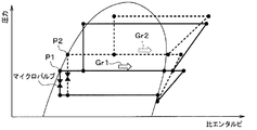
ここで、図7は、第2暖房モードにおける冷媒の状態を示すモリエル線図である。第2暖房モード時の冷媒の状態は、例えば、図7のモリエル線図の実線で示す状態となる。この状態から減圧部17の絞り開度を小さくすると、減圧部17の上流側の圧力が点P1〜点P2へと上昇し、冷媒の状態が図7のモリエル線図の破線で示す状態に変化する。
Here, FIG. 7 is a Moriel diagram showing the state of the refrigerant in the second heating mode. The state of the refrigerant in the second heating mode is, for example, the state shown by the solid line in the Moriel diagram of FIG. 7. When the throttle opening of the
減圧部17の上流側の圧力が上昇すると、圧縮機11の中間圧ポート11bへ流入する冷媒の密度が大きくなるので、圧縮機11の中間圧ポート11bへ流入する冷媒流量が増加する。すなわち、減圧部17の絞り開度を小さくすると、圧縮機11の中間圧ポート11bへ流入する冷媒流量Gr2が、減圧部17の絞り開度を小さくする前の冷媒流量Gr1よりも増える。これにより、室内凝縮器12に流れる冷媒の流量が増え、暖房能力が増加する。
When the pressure on the upstream side of the
これらを考慮して、本実施形態の制御装置40は、第2暖房モード時に暖房能力が不足する場合、制御装置40によって、絞り開度が小さくなるように統合弁14の減圧部17を制御する。制御装置40は、第2暖房モード時に暖房能力が不足する場合、マイクロバルブX1への通電を停止し、減圧部17の絞り開度を小さくする。
In consideration of these, when the heating capacity is insufficient in the second heating mode, the
以上説明した統合弁14は、減圧部17の絞り開度が変更可能になっている。このため、ガスインジェクションサイクルに切り替えたとしても、減圧部17の絞り開度をサイクル負荷に適した開度に調整して、性能の向上を図ることができる。
In the
加えて、減圧部17は、マイクロバルブX1によって絞り開度を可変する構成になっているため、電磁弁や電動弁を用いる場合に比べて容易に小型化できる。その理由の1つは、マイクロバルブX1が上述の通り半導体チップにより形成されているということである。また、上述の通り、梃子を利用して熱的な膨張による変位量が増幅されることも、そのような梃子を利用しない電磁弁と比べた小型化に寄与する。
In addition, since the
また、梃子を利用しているので、熱的な膨張による変位量を可動部X128の移動量より抑えることができる。したがって、可動部X128を駆動するための消費電力も低減することができる。また、電磁弁の駆動時における衝撃音を無くすことができるので、騒音を低減することができる。また、複数本の第1リブX123、複数本の第2リブX124の変位は熱に起因して発生するので、騒音低減効果が高い。 Further, since the lever is used, the amount of displacement due to thermal expansion can be suppressed from the amount of movement of the movable portion X128. Therefore, the power consumption for driving the movable portion X128 can also be reduced. Further, since the impact noise when the solenoid valve is driven can be eliminated, the noise can be reduced. Further, since the displacement of the plurality of first ribs X123 and the plurality of second ribs X124 is caused by heat, the noise reduction effect is high.
また、減圧部17は、開度が固定された固定絞り170を含んでいる。そして、マイクロバルブX1は、可動部X128によって第1冷媒孔X16および第2冷媒孔X17の連通および遮断を切り替えることで減圧部17の絞り開度を調整する構成になっている。
Further, the
このように、減圧部17がマイクロバルブX1だけでなく固定絞り170を含む構成となっていれば、マイクロバルブX1における第1冷媒孔X16および第2冷媒孔X17の連通および遮断の切り替えによって減圧部17の絞り開度を段階的に調整できる。また、減圧部17が固定絞り170を含んでいる場合、減圧部17の絞り開度の調整が不要な際にはマイクロバルブX1を駆動させないことで、マイクロバルブX1の駆動頻度を低減して、統合弁14におけるエネルギ消費を抑えることができる。
As described above, if the
上述のように、マイクロバルブX1もバルブモジュールX0もUターンの構造の冷媒流路を有しているので、ロワーボデー141の掘り込みを少なくすることができる。つまり、バルブモジュールX0を配置するためにロワーボデー141に形成された凹みの深さを抑えることができる。その理由は以下の通りである。
As described above, since both the micro valve X1 and the valve module X0 have a refrigerant flow path having a U-turn structure, it is possible to reduce the digging of the
例えば、バルブモジュールX0がUターンの構造の冷媒流路を有しておらず、バルブモジュールX0のロワーボデー141側の面に冷媒入口があり、バルブモジュールX0の反対側の面に冷媒出口があったとする。その場合、バルブモジュールX0の両面に、冷媒流路を形成する必要がある。したがって、バルブモジュールX0の両面の冷媒流路までロワーボデー141に収容しようとすると、バルブモジュールX0を配置するためにロワーボデー141に形成しなければならない凹みが深くなってしまう。また、マイクロバルブX1自体が小型であるので、ロワーボデー141の掘り込みを更に低減することができる。
For example, the valve module X0 does not have a refrigerant flow path having a U-turn structure, the refrigerant inlet is on the
また、マイクロバルブX1の両面のうち、第1冷媒孔X16、第2冷媒孔X17が形成される面とは反対側の面に電気配線X6、X7を配置した場合、電気配線X6、X7を大気雰囲気により近い側に置くことができる。したがって、電気配線X6、X7への冷媒雰囲気の影響を低減するためのハーメチック等のシール構造が不要となる。その結果、減圧部17の小型化が実現できる。
Further, when the electrical wirings X6 and X7 are arranged on the surface of both sides of the microvalve X1 opposite to the surface on which the first refrigerant hole X16 and the second refrigerant hole X17 are formed, the electrical wirings X6 and X7 are placed in the atmosphere. Can be placed closer to the atmosphere. Therefore, a sealing structure such as a hermetic for reducing the influence of the refrigerant atmosphere on the electric wirings X6 and X7 becomes unnecessary. As a result, the
また、マイクロバルブX1が軽量であることから、減圧部17が軽量化される。マイクロバルブX1の消費電力が小さいので、減圧部17が省電力化される。
Further, since the micro valve X1 is lightweight, the
(第2実施形態)
次に、第2実施形態について、図16、図17を参照して説明する。本実施形態では、ロワーボデー141に対して固定絞り170が形成されていない点が第1実施形態と相違している。本実施形態では、第1実施形態と異なる部分について主に説明し、第1実施形態と同様の部分について説明を省略することがある。
(Second Embodiment)
Next, the second embodiment will be described with reference to FIGS. 16 and 17. The present embodiment is different from the first embodiment in that the fixed drawing 170 is not formed with respect to the
図16に示すように、ロワーボデー141には、固定絞り170が形成されていない。すなわち、本実施形態の減圧部17は、マイクロバルブX1を含むバルブモジュールX0によって構成されている。
As shown in FIG. 16, the
ここで、減圧部17のマイクロバルブX1は、通電時に、電気配線X6、X7から第1印加点X129、第2印加点X130を介してマイクロバルブX1に供給される電力が大きいほど、非通電時位置に対する可動部X128の移動量も大きくなる。これは、マイクロバルブX1に供給される電力が高いほど、第1リブX123、第2リブX124の温度が高くなり、膨張度合いが大きいからである。例えば、電気配線X6、X7から第1印加点X129、第2印加点X130へ印加される電圧がPWM制御される場合、デューティ比が大きいほど非通電時に対する可動部X128の移動量も大きくなる。
Here, the microvalve X1 of the
このため、マイクロバルブX1は、マイクロバルブX1に供給される電力を調整することで、可動部X128を、非通電時位置と最大通電時位置の間のどの中間位置にでも、停止させることができる。 Therefore, the microvalve X1 can stop the movable portion X128 at any intermediate position between the non-energized position and the maximum energized position by adjusting the electric power supplied to the microvalve X1. ..
例えば、最大通電時位置と非通電時位置からも等距離の位置(すなわち、中央位置)で可動部X128を停止させるには、マイクロバルブX1に供給される電力が、制御範囲内の最大値の半分であればいい。例えば、PWM制御のデューティ比が50%であればいい。 For example, in order to stop the movable portion X128 at a position equidistant from the maximum energized position and the non-energized position (that is, the central position), the electric power supplied to the micro valve X1 is the maximum value within the control range. It should be half. For example, the duty ratio of PWM control may be 50%.
可動部X128が中間位置に停止している場合、第1冷媒孔X16および第2冷媒孔X17は、いずれも貫通孔X120に連通している。しかし、第2冷媒孔X17は、貫通孔Y120に対して全開状態ではなく、100%未満かつ0%よりも大きい開度となっている。可動部X128が中間位置において最大通電位時位置に近づくほど、貫通孔X120に対する第2冷媒孔X17の開度が増大する。 When the movable portion X128 is stopped at an intermediate position, both the first refrigerant hole X16 and the second refrigerant hole X17 communicate with the through hole X120. However, the second refrigerant hole X17 is not fully open with respect to the through hole Y120, and has an opening degree of less than 100% and larger than 0%. As the movable portion X128 approaches the maximum potential current position in the intermediate position, the opening degree of the second refrigerant hole X17 with respect to the through hole X120 increases.
これらを踏まえて、統合弁14のマイクロバルブX1は、可動部X128によって第2冷媒孔X17の開度を調整することで、減圧部17の絞り開度を多段階または連続的に調整可能な構成になっている。すなわち、マイクロバルブX1は、減圧部17の絞り開度を変更可能な可変絞りとして構成されている。
Based on these, the micro valve X1 of the
マイクロバルブX1は、例えば、図17に示すように、制御装置40によるPWM制御のデューティ比が大きくなると、減圧部17の絞り開度を大きくし、PWM制御のデューティ比が小さくなると、減圧部17の絞り開度を小さくする。
For example, as shown in FIG. 17, the microvalve X1 increases the throttle opening of the
制御装置40は、例えば、第2暖房モード時に暖房能力が不足する場合、絞り開度が小さくなるように統合弁14の減圧部17を制御する。すなわち、制御装置40は、第2暖房モード時に暖房能力が不足する場合、PWM制御のデューティ比を小さくすることで減圧部17の絞り開度を小さくする。
For example, when the heating capacity is insufficient in the second heating mode, the
その他の構成および作動は、第1実施形態と同様である。本実施形態の減圧部17は、マイクロバルブX1に供給する電力を調整することで、減圧部17の絞り開度の調整が可能になっている。このように、マイクロバルブX1を減圧部17の絞り開度を変更可能な可変絞りとして構成すれば、マイクロバルブX1における流体孔の開度を変更することで、減圧部17の絞り開度を所望の開度に調整することができる。この結果、ガスインジェクションサイクルに切り替えたとしても、減圧部17の絞り開度をサイクル負荷に適した開度に調整できる。なお、減圧部17がマイクロバルブX1を含んで構成されることで得られる作用効果に関しては、第1実施形態と同様に得ることができる。
Other configurations and operations are the same as in the first embodiment. The
(第2実施形態の変形例)
上述の第2実施形態では、ロワーボデー141に対して固定絞り170が形成されていないものを例示したが、これに限定されない。第2実施形態の減圧部17は、固定絞り170を含むように構成されていてもよい。
(Modified example of the second embodiment)
In the second embodiment described above, the fixed throttle 170 is not formed with respect to the
(第3実施形態)
次に、第3実施形態について、図18〜図28を参照して説明する。本実施形態では、液側弁体181による液冷媒通路141dの開閉が冷媒の圧力差を利用して変更される構成になっている点が第1実施形態と相違している。本実施形態では、第1実施形態と異なる部分について主に説明し、第1実施形態と同様の部分について説明を省略することがある。
(Third Embodiment)
Next, the third embodiment will be described with reference to FIGS. 18 to 28. The present embodiment is different from the first embodiment in that the opening and closing of the liquid
図18および図19に示すように、統合弁14は、液側弁体181が差圧式駆動部材28によって駆動される構成になっている。なお、差圧式駆動部材28は、液側弁体181を駆動する駆動部材である。差圧式駆動部材28は、ピストン281、弾性部材282、マイクロバルブY1を含むバルブモジュールY0等で構成されている。
As shown in FIGS. 18 and 19, the
差圧式駆動部材28は、マイクロバルブY1の作動により、液側弁体181に作用する圧力を変化させることによって、液側弁体181を変位させるパイロット式の弁機構で構成されている。
The differential pressure
ピストン281は、液側弁体181と一体に変位するように、シャフト181cの端部に連結されている。ピストン281は、ロワーボデー141に形成されたシリンダ室280に対して摺動可能に収容されている。なお、ピストン281は、液側弁体181において冷媒の圧力を受ける受圧部を構成している。
The
シリンダ室280は、ロワーボデー141のうち弁座部141fに対向する部位の内部に形成されている。具体的には、シリンダ室280は、ロワーボデー141に形成された有底孔141gと有底孔141gを閉塞する蓋部141hとで区画形成されている。シリンダ室280は、ピストン281によって中間圧室280aと圧力制御室280bとに分割されている。
The cylinder chamber 280 is formed inside a portion of the
中間圧室280aは、有底孔141gの底部と当該底部に対向するピストン281の一面との間に形成される空間である。中間圧室280aは、冷媒流入口141aを流れる冷媒が導入される空間である。中間圧室280aは、ロワーボデー141に形成された冷媒の導入路280cを介して冷媒流入口141aに連通している。
The intermediate pressure chamber 280a is a space formed between the bottom portion of the bottomed
圧力制御室280bは、蓋部141hと蓋部141hに対向するピストン281の他面との間に形成される空間である。圧力制御室280bは、液側弁体181を開弁側または閉弁側に押圧するための冷媒が導入される空間である。圧力制御室280bには、ピストン281を有底孔141gに向けて付勢する弾性部材282が配置されている。弾性部材282は、コイルバネ等で構成されている。
The pressure control chamber 280b is a space formed between the
本実施形態の液側弁体181は、ピストン281に連動して変位する。ピストン281は、ピストン281を作用する圧力、弾性部材282から受ける荷重によって決定される。なお、ピストン281には、一面に対して冷媒流入口141aの冷媒圧力である中間圧力Pmが作用し、他面に対して圧力制御室280bの冷媒圧力である制御圧力Pcが作用する。
The liquid-
差圧式駆動部材28では、制御圧力Pcが低圧圧力Plと同等の圧力となる場合、中間圧力Pmと制御圧力Pcとの圧力差が最大となる。この際、中間圧力Pmと制御圧力Pcとの圧力差による荷重が弾性部材282の付勢力を上回ることでピストン281が蓋部141hに近づくように変位する。すなわち、図19に示すように、液側弁体181が弁座部141fから離間することで、液冷媒通路141dが開放される。
In the differential pressure
この状態から制御圧力Pcが低圧圧力Plよりも高くなると、中間圧力Pmと制御圧力Pcとの圧力差が小さくなることで、ピストン281が有底孔141gの底部に近づくように変位する。そして、制御圧力Pcが中間圧力Pmと同等の圧力となると、ピストン281が弾性部材282によって有底孔141gの底部に向けて付勢される。これにより、図18に示すように、液側弁体181が弁座部141fに当接することで、液冷媒通路141dが閉鎖される。
When the control pressure Pc becomes higher than the low pressure pressure Pl from this state, the pressure difference between the intermediate pressure Pm and the control pressure Pc becomes small, so that the
このように、統合弁14は、図20に示すように、制御圧力Pcが低圧圧力Plと同程度の圧力となる場合に液冷媒通路141dが開放され、制御圧力Pcが中間圧力Pmと同程度の圧力となる場合に液冷媒通路141dが閉鎖される構成になっている。本実施形態の統合弁14は、制御圧力PcがバルブモジュールY0のマイクロバルブY1によって調整される構成になっている。以下、バルブモジュールY0の詳細について説明する。
As described above, in the
[バルブモジュールY0の構成]
バルブモジュールY0は、ピストン281に作用する圧力を調整するマイクロバルブY1を含んでいる。バルブモジュールY0は、ロワーボデー141に対して一体的に取り付けられている。ロワーボデー141は、マイクロバルブY1の取付対象となる被取付対象物を構成している。
[Valve module Y0 configuration]
The valve module Y0 includes a microvalve Y1 that regulates the pressure acting on the
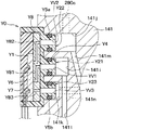
図21に示すように、ロワーボデー141には、後述するバルブモジュールY0の第1突出部Y21、第2突出部Y22、第3突出部Y23が嵌め合わされる第1凹部141i、第2凹部141j、第3凹部141kが形成されている。第1凹部141i、第2凹部141j、第3凹部141kは、ロワーボデー141の側面を見たときに、第2凹部141j、第1凹部141i、第3凹部141kの順に直線状に並ぶように配置されている。
As shown in FIG. 21, the
第1凹部141iは、ロワーボデー141に形成された第1連通路141lを介して圧力制御室280bに連通している。第2凹部141jは、ロワーボデー141に形成された第2連通路141mを介して冷媒流入口141aに連通している。第3凹部141kは、ロワーボデー141に形成された第3連通路141nを介して圧力導入通路19に連通している。
The first recess 141i communicates with the pressure control chamber 280b via the first communication passage 141l formed in the
バルブモジュールY0は、マイクロバルブY1、バルブケーシングY2、封止部材Y3、3つのOリングY4、Y5a、Y5b、2本の電気配線Y6、Y7、変換プレートY8を有している。 The valve module Y0 has a micro valve Y1, a valve casing Y2, a sealing member Y3, three O-rings Y4, Y5a, Y5b, two electrical wirings Y6, Y7, and a conversion plate Y8.
マイクロバルブY1は、板形状の弁部品であり、主として半導体チップによって構成されている。マイクロバルブY1は、半導体チップ以外の部品を有していてもいなくてもよい。したがって、マイクロバルブY1を小型に構成できる。マイクロバルブY1は、圧力制御室280bにおける冷媒の圧力を調整するための調圧部品でもある。マイクロバルブY1の厚さ方向の長さは例えば2mmであり、厚さ方向に直交する長手方向の長さは例えば10mmであり、長手方向にも厚さ方向にも直交する短手方向の長さは例えば5mmであるが、これに限定されない。マイクロバルブY1への供給電力が変動することで、マイクロバルブY1の流路構成が変化する。マイクロバルブY1は、液側弁体181を駆動するパイロット弁として機能する。
The microvalve Y1 is a plate-shaped valve component, and is mainly composed of a semiconductor chip. The microvalve Y1 may or may not have a component other than the semiconductor chip. Therefore, the micro valve Y1 can be configured in a small size. The micro valve Y1 is also a pressure adjusting component for adjusting the pressure of the refrigerant in the pressure control chamber 280b. The length of the microvalve Y1 in the thickness direction is, for example, 2 mm, the length in the longitudinal direction orthogonal to the thickness direction is, for example, 10 mm, and the length in the lateral direction orthogonal to both the longitudinal direction and the thickness direction. Is, for example, 5 mm, but is not limited thereto. As the power supplied to the micro valve Y1 fluctuates, the flow path configuration of the micro valve Y1 changes. The micro valve Y1 functions as a pilot valve for driving the liquid
電気配線Y6、Y7は、マイクロバルブY1の2つの板面のうち、バルブケーシングY2とは反対側の面から伸びて、封止部材Y3、バルブケーシングY2内を通過して、バルブモジュールY0の外部にある電源に接続される。これにより、電気配線Y6、Y7を通して、電源からマイクロバルブY1に電力が供給される。 The electrical wirings Y6 and Y7 extend from the surface of the two plate surfaces of the microvalve Y1 opposite to the valve casing Y2, pass through the sealing member Y3 and the valve casing Y2, and pass through the sealing member Y3 and the valve casing Y2 to the outside of the valve module Y0. Connected to the power supply at. As a result, electric power is supplied from the power source to the microvalve Y1 through the electric wirings Y6 and Y7.
変換プレートY8は、マイクロバルブY1とバルブケーシングY2の間に配置される板形状の部材である。変換プレートY8は、ガラス基板である。変換プレートY8の2つの板面の一方側は、マイクロバルブY1に対して接着剤で固定され、他方側はバルブケーシングY2に対して接着剤で固定されている。変換プレートY8には、マイクロバルブY1の後述する3つの冷媒孔とバルブケーシングY2の3つの連通孔とを繋げるための流路Y81、Y82、Y83が形成されている。これら流路Y81、Y82、Y83は、一列に並ぶ上記3つの冷媒孔のピッチと一列に並ぶ上記3つの連通孔のピッチの違いを吸収するための部材である。流路Y81、Y82、Y83は、変換プレートY8の2つの板面の一方から他方に貫通している。 The conversion plate Y8 is a plate-shaped member arranged between the microvalve Y1 and the valve casing Y2. The conversion plate Y8 is a glass substrate. One side of the two plate surfaces of the conversion plate Y8 is fixed to the microvalve Y1 with an adhesive, and the other side is fixed to the valve casing Y2 with an adhesive. The conversion plate Y8 is formed with flow paths Y81, Y82, and Y83 for connecting the three refrigerant holes described later of the microvalve Y1 and the three communication holes of the valve casing Y2. These flow paths Y81, Y82, and Y83 are members for absorbing the difference between the pitches of the three refrigerant holes arranged in a row and the pitches of the three communication holes arranged in a row. The flow paths Y81, Y82, and Y83 penetrate from one of the two plate surfaces of the conversion plate Y8 to the other.
バルブケーシングY2は、マイクロバルブY1および変換プレートY8を収容する樹脂製のケーシングである。バルブケーシングY2は、ポリフェニレンサルファイドを主成分として樹脂成形によって形成されている。バルブケーシングY2は、線膨張係数が、マイクロバルブY1の線膨張係数とロワーボデー141の線膨張係数の間の値となるように構成されている。なお、バルブケーシングY2は、マイクロバルブY1をロワーボデー141に対して取り付けるための部品取付部を構成している。バルブケーシングY2は、一方側に底壁を有し、他方側が開放された箱体である。バルブケーシングY2の底壁は、マイクロバルブY1および変換プレートY8がロワーボデー141に直接接しないように、ロワーボデー141とマイクロバルブY1の間に介在する。そして、この底壁の一方側の面がロワーボデー141に接触して固定され、他方側の面が変換プレートY8に接触して固定される。
The valve casing Y2 is a resin casing that houses the microvalve Y1 and the conversion plate Y8. The valve casing Y2 is formed by resin molding containing polyphenylene sulfide as a main component. The valve casing Y2 is configured such that the coefficient of linear expansion is a value between the coefficient of linear expansion of the microvalve Y1 and the coefficient of linear expansion of the
このようになっていることで、マイクロバルブY1とロワーボデー141の線膨張係数の違いをバルブケーシングY2が吸収できる。これは、バルブケーシングY2の線膨張係数が、マイクロバルブY1の線膨張係数とロワーボデー141の線膨張係数の間の値となっているからである。なお、変換プレートY8の線膨張係数は、マイクロバルブY1の線膨張係数とバルブケーシングY2の線膨張係数の間の値となっている。ここで、バルブケーシングY2は、マイクロバルブY1をロワーボデー141に対して取り付けるための部品取付部を構成している。
In this way, the valve casing Y2 can absorb the difference in the linear expansion coefficient between the micro valve Y1 and the
また、バルブケーシングY2の底壁は、マイクロバルブY1に対向する板形状のベース部Y20と、マイクロバルブY1から離れる方向に当該ベース部Y20から突出する柱形状の第1突出部Y21、第2突出部Y22、第3突出部Y23を有する。 Further, the bottom wall of the valve casing Y2 has a plate-shaped base portion Y20 facing the microvalve Y1 and a pillar-shaped first protruding portion Y21 and a second protruding portion Y21 protruding from the base portion Y20 in a direction away from the microvalve Y1. It has a portion Y22 and a third protruding portion Y23.
第1突出部Y21、第2突出部Y22、第3突出部Y23は、ロワーボデー141に形成された第1凹部141i、第2凹部141j、第3凹部141kに嵌め込まれている。第1突出部Y21には、マイクロバルブY1側端からその反対側端まで貫通する第1連通孔YV1が形成されている。第2突出部Y22には、マイクロバルブY1側端からその反対側端まで貫通する第2連通孔YV2が形成されている。第3突出部Y23には、マイクロバルブY1側端からその反対側端まで貫通する第3連通孔YV3が形成されている。第1連通孔YV1、第2連通孔YV2、第3連通孔YV3は一列に並んでおり、第2連通孔YV2と第3連通孔YV3の間に第1連通孔YV1が位置する。
The first protruding portion Y21, the second protruding portion Y22, and the third protruding portion Y23 are fitted into the first recess 141i, the
第1連通孔YV1のマイクロバルブY1側端は、変換プレートY8に形成された流路Y81のバルブケーシングY2側端に連通している。第2連通孔YV2のマイクロバルブY1側端は、変換プレートY8に形成された流路Y82のバルブケーシングY2側端に連通している。第3連通孔YV3のマイクロバルブY1側端は、変換プレートY8に形成された流路Y83のバルブケーシングY2側端に連通している。 The microvalve Y1 side end of the first communication hole YV1 communicates with the valve casing Y2 side end of the flow path Y81 formed in the conversion plate Y8. The microvalve Y1 side end of the second communication hole YV2 communicates with the valve casing Y2 side end of the flow path Y82 formed in the conversion plate Y8. The microvalve Y1 side end of the third communication hole YV3 communicates with the valve casing Y2 side end of the flow path Y83 formed in the conversion plate Y8.
封止部材Y3は、バルブケーシングY2の開放された上記他方側を封止するエポキシ樹脂製の部材である。封止部材Y3は、マイクロバルブY1の表裏の2つの板面のうち、変換プレートY8側とは反対側の板面の全体を覆う。また、封止部材Y3は、変換プレートY8の2つの板面のうち、バルブケーシングY2の底壁側とは反対側の板面の一部を覆う。また、封止部材Y3は、電気配線Y6、Y7を覆うことで、電気配線Y6、Y7の防水および絶縁を実現する。封止部材Y3は樹脂ポッティング等によって形成される。 The sealing member Y3 is a member made of epoxy resin that seals the other open side of the valve casing Y2. The sealing member Y3 covers the entire plate surface on the side opposite to the conversion plate Y8 side of the two plate surfaces on the front and back of the micro valve Y1. Further, the sealing member Y3 covers a part of the plate surface of the conversion plate Y8 on the side opposite to the bottom wall side of the valve casing Y2. Further, the sealing member Y3 covers the electric wirings Y6 and Y7 to realize waterproofing and insulation of the electric wirings Y6 and Y7. The sealing member Y3 is formed by resin potting or the like.
OリングY4は、第1突出部Y21の外周に取り付けられ、ロワーボデー141と第1突出部Y21の間を封止することで、統合弁14の外部かつ冷媒回路の外部への冷媒の漏出を抑制する。OリングY5aは、第2突出部Y22の外周に取り付けられ、ロワーボデー141と第2突出部Y22の間を封止することで、統合弁14の外部かつ冷媒回路の外部への冷媒の漏出を抑制する。OリングY5bは、第3突出部Y23の外周に取り付けられ、ロワーボデー141と第3突出部Y23の間を封止することで、統合弁14の外部かつ冷媒回路の外部への冷媒の漏出を抑制する。
The O-ring Y4 is attached to the outer periphery of the first protruding portion Y21, and by sealing between the
[マイクロバルブY1の構成]
ここで、マイクロバルブY1の構成について更に説明する。マイクロバルブY1は、図22、図23に示すように、いずれも半導体である第1外層Y11、中間層Y12、第2外層Y13を備えたMEMSである。第1外層Y11、中間層Y12、第2外層Y13は、それぞれが同じ外形を有する長方形の板形状の部材であり、第1外層Y11、中間層Y12、第2外層Y13の順に積層されている。第1外層Y11、中間層Y12、第2外層Y13のうち、第2外層Y13が、バルブケーシングY2の底壁に最も近い側に配置される。後述する第1外層Y11、中間層Y12、第2外層Y13の構造は、化学的エッチング等の半導体製造プロセスによって形成される。
[Structure of micro valve Y1]
Here, the configuration of the microvalve Y1 will be further described. As shown in FIGS. 22 and 23, the microvalve Y1 is a MEMS having a first outer layer Y11, an intermediate layer Y12, and a second outer layer Y13, all of which are semiconductors. The first outer layer Y11, the intermediate layer Y12, and the second outer layer Y13 are rectangular plate-shaped members having the same outer shape, and the first outer layer Y11, the intermediate layer Y12, and the second outer layer Y13 are laminated in this order. Of the first outer layer Y11, the intermediate layer Y12, and the second outer layer Y13, the second outer layer Y13 is arranged on the side closest to the bottom wall of the valve casing Y2. The structures of the first outer layer Y11, the intermediate layer Y12, and the second outer layer Y13, which will be described later, are formed by a semiconductor manufacturing process such as chemical etching.
第1外層Y11は、表面に非導電性の酸化膜のある導電性の半導体部材である。第1外層Y11には、図22に示すように、表裏に貫通する2つの貫通孔Y14、Y15が形成されている。この貫通孔Y14、Y15に、それぞれ、電気配線Y6、Y7のマイクロバルブY1側端が挿入される。 The first outer layer Y11 is a conductive semiconductor member having a non-conductive oxide film on its surface. As shown in FIG. 22, two through holes Y14 and Y15 penetrating the front and back are formed in the first outer layer Y11. The microvalve Y1 side ends of the electrical wirings Y6 and Y7 are inserted into the through holes Y14 and Y15, respectively.
第2外層Y13は、表面に非導電性の酸化膜のある導電性の半導体部材である。第2外層Y13には、図22、図24、図25に示すように、表裏に貫通する第1冷媒孔Y16、第2冷媒孔Y17、第3冷媒孔Y18が形成されている。第1冷媒孔Y16、第2冷媒孔Y17、第3冷媒孔Y18の各々の水力直径は、例えば0.1mm以上かつ3mm以下であるが、これに限定されない。第1冷媒孔Y16、第2冷媒孔Y17、第3冷媒孔Y18は、それぞれ、第1流体孔、第2流体孔、第3流体孔に対応する。 The second outer layer Y13 is a conductive semiconductor member having a non-conductive oxide film on its surface. As shown in FIGS. 22, 24, and 25, the second outer layer Y13 is formed with a first refrigerant hole Y16, a second refrigerant hole Y17, and a third refrigerant hole Y18 penetrating the front and back surfaces. The hydraulic diameters of the first refrigerant holes Y16, the second refrigerant holes Y17, and the third refrigerant holes Y18 are, for example, 0.1 mm or more and 3 mm or less, but are not limited thereto. The first refrigerant hole Y16, the second refrigerant hole Y17, and the third refrigerant hole Y18 correspond to the first fluid hole, the second fluid hole, and the third fluid hole, respectively.
図25に示すように、第1冷媒孔Y16、第2冷媒孔Y17、第3冷媒孔Y18は、それぞれ、変換プレートY8の流路Y81、Y82、Y83に連通する。第1冷媒孔Y16、第2冷媒孔Y17、第3冷媒孔Y18は、一列に並んでいる。第2冷媒孔Y17と第3冷媒孔Y18の間に第1冷媒孔Y16が配置される。 As shown in FIG. 25, the first refrigerant hole Y16, the second refrigerant hole Y17, and the third refrigerant hole Y18 communicate with the flow paths Y81, Y82, and Y83 of the conversion plate Y8, respectively. The first refrigerant hole Y16, the second refrigerant hole Y17, and the third refrigerant hole Y18 are arranged in a row. The first refrigerant hole Y16 is arranged between the second refrigerant hole Y17 and the third refrigerant hole Y18.
中間層Y12は、導電性の半導体部材であり、第1外層Y11と第2外層Y13に挟まれている。中間層Y12は、第1外層Y11の酸化膜と第2外層Y13の酸化膜に接触するので、第1外層Y11と第2外層Y13とも電気的に非導通である。中間層Y12は、図24に示すように、第1固定部Y121、第2固定部Y122、複数本の第1リブY123、複数本の第2リブY124、スパインY125、アームY126、梁Y127、可動部Y128を有している。 The intermediate layer Y12 is a conductive semiconductor member, and is sandwiched between the first outer layer Y11 and the second outer layer Y13. Since the intermediate layer Y12 comes into contact with the oxide film of the first outer layer Y11 and the oxide film of the second outer layer Y13, both the first outer layer Y11 and the second outer layer Y13 are electrically non-conducting. As shown in FIG. 24, the intermediate layer Y12 has a first fixed portion Y121, a second fixed portion Y122, a plurality of first ribs Y123, a plurality of second ribs Y124, a spine Y125, an arm Y126, a beam Y127, and a movable beam. It has a part Y128.
第1固定部Y121は、第1外層Y11、第2外層Y13に対して固定された部材である。第1固定部Y121は、第2固定部Y122、第1リブY123、第2リブY124、スパインY125、アームY126、梁Y127、可動部Y128を同じ1つの流体室Y19内に囲むように形成されている。流体室Y19は、第1固定部Y121、第1外層Y11、第2外層Y13によって囲まれた室である。流体室Y19は、圧力制御室280bに導入する冷媒が流通する調圧用流体室である。第1固定部Y121、第1外層Y11、第2外層Y13は、全体として基部および調圧用基部に対応する。なお、電気配線Y6、Y7は複数の第1リブY123および複数の第2リブY124の温度を変化させて変位させるための電気配線である。 The first fixing portion Y121 is a member fixed to the first outer layer Y11 and the second outer layer Y13. The first fixed portion Y121 is formed so as to surround the second fixed portion Y122, the first rib Y123, the second rib Y124, the spine Y125, the arm Y126, the beam Y127, and the movable portion Y128 in the same fluid chamber Y19. There is. The fluid chamber Y19 is a chamber surrounded by a first fixing portion Y121, a first outer layer Y11, and a second outer layer Y13. The fluid chamber Y19 is a pressure adjusting fluid chamber through which the refrigerant introduced into the pressure control chamber 280b flows. The first fixing portion Y121, the first outer layer Y11, and the second outer layer Y13 correspond to the base portion and the pressure adjusting base portion as a whole. The electrical wirings Y6 and Y7 are electrical wirings for changing the temperature of the plurality of first ribs Y123 and the plurality of second ribs Y124 to displace them.
第1固定部Y121の第1外層Y11および第2外層Y13に対する固定は、冷媒が流体室Y19から第1冷媒孔Y16、第2冷媒孔Y17、第3冷媒孔Y18以外を通ってマイクロバルブY1から漏出することを抑制するような形態で、行われている。 In the fixing of the first fixing portion Y121 to the first outer layer Y11 and the second outer layer Y13, the refrigerant passes from the fluid chamber Y19 to the microvalve Y1 through other than the first refrigerant hole Y16, the second refrigerant hole Y17, and the third refrigerant hole Y18. It is done in a form that suppresses leakage.
第2固定部Y122は、第1外層Y11、第2外層Y13に対して固定される。第2固定部Y122は、第1固定部Y121に取り囲まれると共に、第1固定部Y121から離れて配置される。 The second fixing portion Y122 is fixed to the first outer layer Y11 and the second outer layer Y13. The second fixed portion Y122 is surrounded by the first fixed portion Y121 and is arranged away from the first fixed portion Y121.
複数本の第1リブY123、複数本の第2リブY124、スパインY125、アームY126、梁Y127、可動部Y128は、第1外層Y11、第2外層Y13に対して固定されておらず、第1外層Y11、第2外層Y13に対して変位可能である。 The plurality of first ribs Y123, the plurality of second ribs Y124, the spine Y125, the arm Y126, the beam Y127, and the movable portion Y128 are not fixed to the first outer layer Y11 and the second outer layer Y13, and are the first. It is displaceable with respect to the outer layer Y11 and the second outer layer Y13.
スパインY125は、中間層Y12の矩形形状の短手方向に伸びる細長い棒形状を有している。スパインY125の長手方向の一端は、梁Y127に接続されている。 The spine Y125 has an elongated rod shape extending in the lateral direction of the rectangular shape of the intermediate layer Y12. One end of the spine Y125 in the longitudinal direction is connected to the beam Y127.
複数本の第1リブY123は、スパインY125の長手方向に直交する方向におけるスパインY125の一方側に配置される。そして、複数本の第1リブY123は、スパインY125の長手方向に並んでいる。各第1リブY123は、細長い棒形状を有しており、温度に応じて伸縮可能となっている。 The plurality of first ribs Y123 are arranged on one side of the spine Y125 in a direction orthogonal to the longitudinal direction of the spine Y125. The plurality of first ribs Y123 are arranged in the longitudinal direction of the spine Y125. Each first rib Y123 has an elongated rod shape and can be expanded and contracted according to the temperature.
各第1リブY123は、その長手方向の一端で第1固定部Y121に接続され、他端でスパインY125に接続される。そして、各第1リブY123は、第1固定部Y121側からスパインY125側に近付くほど、スパインY125の長手方向の梁Y127側に向けてオフセットされるよう、スパインY125に対して斜行している。そして、複数の第1リブY123は、互いに対して平行に伸びている。 Each first rib Y123 is connected to the first fixing portion Y121 at one end in the longitudinal direction thereof and to the spine Y125 at the other end. Each of the first ribs Y123 is skewed with respect to the spine Y125 so as to approach the spine Y125 side from the first fixing portion Y121 side so as to be offset toward the beam Y127 side in the longitudinal direction of the spine Y125. .. The plurality of first ribs Y123 extend in parallel with each other.
複数本の第2リブY124は、スパインY125の長手方向に直交する方向におけるスパインY125の他方側に配置される。そして、複数本の第2リブY124は、スパインY125の長手方向に並んでいる。各第2リブY124は、細長い棒形状を有しており、温度に応じて伸縮可能となっている。 The plurality of second ribs Y124 are arranged on the other side of the spine Y125 in a direction orthogonal to the longitudinal direction of the spine Y125. The plurality of second ribs Y124 are arranged in the longitudinal direction of the spine Y125. Each second rib Y124 has an elongated rod shape and can be expanded and contracted according to the temperature.
各第2リブY124は、その長手方向の一端で第2固定部Y122に接続され、他端でスパインY125に接続される。そして、各第2リブY124は、第2固定部Y122側からスパインY125側に近付くほど、スパインY125の長手方向の梁Y127側に向けてオフセットされるよう、スパインY125に対して斜行している。そして、複数の第2リブY124は、互いに対して平行に伸びている。 Each second rib Y124 is connected to the second fixing portion Y122 at one end in the longitudinal direction thereof and to the spine Y125 at the other end. Each of the second ribs Y124 is skewed with respect to the spine Y125 so as to approach the spine Y125 side from the second fixed portion Y122 side so as to be offset toward the beam Y127 side in the longitudinal direction of the spine Y125. .. The plurality of second ribs Y124 extend in parallel with each other.
複数本の第1リブY123、複数本の第2リブY124、スパインY125は、全体として、駆動部および調圧用駆動部に対応する。 The plurality of first ribs Y123, the plurality of second ribs Y124, and the spine Y125 correspond to the drive unit and the pressure adjusting drive unit as a whole.
アームY126は、スパインY125と非直交かつ平行に伸びる細長い棒形状を有している。アームY126の長手方向の一端は梁Y127に接続されており、他端は第1固定部Y121に接続されている。 The arm Y126 has an elongated rod shape extending non-orthogonally and parallel to the spine Y125. One end of the arm Y126 in the longitudinal direction is connected to the beam Y127, and the other end is connected to the first fixing portion Y121.
梁Y127は、スパインY125およびアームY126に対して約90°で交差する方向に伸びる細長い棒形状を有している。梁Y127の一端は、可動部Y128に接続されている。アームY126と梁Y127は、全体として、増幅部および調圧用増幅部に対応する。 The beam Y127 has an elongated rod shape extending in a direction intersecting the spine Y125 and the arm Y126 at about 90 °. One end of the beam Y127 is connected to the movable portion Y128. The arm Y126 and the beam Y127 correspond to the amplification unit and the pressure adjusting amplification unit as a whole.
アームY126と梁Y127の接続位置YP1、スパインY125と梁Y127の接続位置YP2、梁Y127と可動部Y128の接続位置YP3は、梁Y127の長手方向に沿って、この順に並んでいる。そして、第1固定部Y121とアームY126との接続点をヒンジYP0とすると、中間層Y12の板面に平行な面内におけるヒンジYP0から接続位置YP2までの直線距離よりも、ヒンジYP0から接続位置YP3までの直線距離の方が、長い。例えば、前者の直線距離を後者の直線距離で除算した値は、1/5以下であってもよいし、1/10以下であってもよい。なお、ヒンジYP0は、調圧用ヒンジでもある。接続位置YP3は、調圧用接続位置でもある。 The connection position YP1 between the arm Y126 and the beam Y127, the connection position YP2 between the spine Y125 and the beam Y127, and the connection position YP3 between the beam Y127 and the movable portion Y128 are arranged in this order along the longitudinal direction of the beam Y127. If the connection point between the first fixing portion Y121 and the arm Y126 is a hinge YP0, the connection position from the hinge YP0 is more than the linear distance from the hinge YP0 to the connection position YP2 in the plane parallel to the plate surface of the intermediate layer Y12. The straight line distance to YP3 is longer. For example, the value obtained by dividing the former straight line distance by the latter straight line distance may be 1/5 or less, or may be 1/10 or less. The hinge YP0 is also a pressure adjusting hinge. The connection position YP3 is also a pressure adjustment connection position.
可動部Y128は、流体室Y19を流れる冷媒の圧力を調整する調圧用可動部である。可動部Y128は、その外形が、梁Y127の長手方向に対して概ね90°の方向に伸びる矩形形状を有している。この可動部Y128は、流体室Y19内において梁Y127と一体に動くことができる。そして、可動部Y128は、中間層Y12の表裏に貫通する貫通孔Y120を囲む枠形状となっている。したがって、貫通孔Y120も、可動部Y128と一体的に移動する。貫通孔Y120は、流体室Y19の一部である。 The movable portion Y128 is a pressure adjusting movable portion that adjusts the pressure of the refrigerant flowing through the fluid chamber Y19. The movable portion Y128 has a rectangular shape whose outer shape extends in a direction of approximately 90 ° with respect to the longitudinal direction of the beam Y127. The movable portion Y128 can move integrally with the beam Y127 in the fluid chamber Y19. The movable portion Y128 has a frame shape surrounding the through hole Y120 penetrating the front and back of the intermediate layer Y12. Therefore, the through hole Y120 also moves integrally with the movable portion Y128. The through hole Y120 is a part of the fluid chamber Y19.
可動部Y128は、上記のように動くことで、第2冷媒孔Y17の貫通孔Y120に対する開度および、第3冷媒孔Y18の貫通孔Y120に対する開度を変更する。第1冷媒孔Y16は、貫通孔Y120に対して常に全開で連通している。 By moving as described above, the movable portion Y128 changes the opening degree of the second refrigerant hole Y17 with respect to the through hole Y120 and the opening degree of the third refrigerant hole Y18 with respect to the through hole Y120. The first refrigerant hole Y16 always communicates with the through hole Y120 in full opening.
また、第1固定部Y121のうち、複数の第1リブY123と接続する部分の近傍の第1印加点Y129には、図22に示した第1外層Y11の貫通孔Y14を通った電気配線Y6のマイクロバルブY1側端が接続される。また、第2固定部Y122の第2印加点Y130には、図22に示した第1外層Y11の貫通孔Y15を通った電気配線Y7のマイクロバルブY1側端が接続される。 Further, at the first application point Y129 in the vicinity of the portion of the first fixed portion Y121 connected to the plurality of first ribs Y123, the electrical wiring Y6 passing through the through hole Y14 of the first outer layer Y11 shown in FIG. 22 The Y1 side end of the micro valve is connected. Further, the microvalve Y1 side end of the electric wiring Y7 passing through the through hole Y15 of the first outer layer Y11 shown in FIG. 22 is connected to the second application point Y130 of the second fixing portion Y122.
[バルブモジュールY0の作動]
ここで、バルブモジュールY0の作動について説明する。マイクロバルブY1への通電が開始されると、電気配線Y6、Y7から第1印加点Y129、第2印加点Y130の間に電圧が印加される。すると、複数の第1リブY123、複数の第2リブY124を電流が流れる。この電流によって、複数の第1リブY123、複数の第2リブY124が発熱する。その結果、複数の第1リブY123、複数の第2リブY124の各々が、その長手方向に膨張する。
[Operation of valve module Y0]
Here, the operation of the valve module Y0 will be described. When the energization of the microvalve Y1 is started, a voltage is applied between the electrical wirings Y6 and Y7 to the first application point Y129 and the second application point Y130. Then, a current flows through the plurality of first ribs Y123 and the plurality of second ribs Y124. Due to this current, the plurality of first ribs Y123 and the plurality of second ribs Y124 generate heat. As a result, each of the plurality of first ribs Y123 and the plurality of second ribs Y124 expands in the longitudinal direction thereof.
このような熱的な膨張の結果、複数の第1リブY123、複数の第2リブY124は、スパインY125を接続位置YP2側に付勢する。付勢されたスパインY125は、接続位置YP2において、梁Y127を押す。このように、接続位置YP2は付勢位置および調圧用付勢位置に対応する。 As a result of such thermal expansion, the plurality of first ribs Y123 and the plurality of second ribs Y124 urge the spine Y125 toward the connection position YP2. The urged spine Y125 pushes the beam Y127 at the connection position YP2. In this way, the connection position YP2 corresponds to the urging position and the pressure adjusting urging position.
そして、梁Y127とアームY126から成る部材は、ヒンジYP0を支点として、接続位置YP2を力点として、一体に姿勢を変える。その結果、梁Y127のアームY126とは反対側の端部に接続された可動部Y128も、その長手方向の、スパインY125が梁Y127を押す側に、移動する。 Then, the member including the beam Y127 and the arm Y126 integrally changes the posture with the hinge YP0 as the fulcrum and the connection position YP2 as the power point. As a result, the movable portion Y128 connected to the end of the beam Y127 opposite to the arm Y126 also moves in the longitudinal direction to the side where the spine Y125 pushes the beam Y127.
また、マイクロバルブY1への通電が停止されたときは、電気配線Y6、Y7から第1印加点Y129、第2印加点Y130への電圧印加が停止される。すると、複数の第1リブY123、複数の第2リブY124を電流が流れなくなり、複数の第1リブY123、複数の第2リブY124の温度が低下する。その結果、複数の第1リブY123、複数の第2リブY124の各々が、その長手方向に収縮する。 When the energization of the microvalve Y1 is stopped, the voltage application from the electrical wirings Y6 and Y7 to the first application point Y129 and the second application point Y130 is stopped. Then, the current does not flow through the plurality of first ribs Y123 and the plurality of second ribs Y124, and the temperatures of the plurality of first ribs Y123 and the plurality of second ribs Y124 decrease. As a result, each of the plurality of first ribs Y123 and the plurality of second ribs Y124 contracts in the longitudinal direction thereof.
このような熱的な収縮の結果、複数の第1リブY123、複数の第2リブY124は、スパインY125を接続位置YP2とは反対側に付勢する。付勢されたスパインY125は、接続位置YP2において、梁Y127を引っ張る。その結果、梁Y127とアームY126から成る部材は、ヒンジYP0を支点として、接続位置YP2を力点として、一体に姿勢を変える。その結果、梁Y127のアームY126とは反対側の端部に接続された可動部Y128も、その長手方向の、スパインY125が梁Y127を引っ張る側に、移動する。その移動の結果、可動部Y128は、所定の非通電時位置で停止する。 As a result of such thermal contraction, the plurality of first ribs Y123 and the plurality of second ribs Y124 urge the spine Y125 to the side opposite to the connection position YP2. The urged spine Y125 pulls the beam Y127 at the connection position YP2. As a result, the member including the beam Y127 and the arm Y126 changes their postures integrally with the hinge YP0 as the fulcrum and the connection position YP2 as the power point. As a result, the movable portion Y128 connected to the end of the beam Y127 opposite to the arm Y126 also moves in the longitudinal direction to the side where the spine Y125 pulls the beam Y127. As a result of the movement, the movable portion Y128 stops at a predetermined non-energized position.
このようなマイクロバルブY1への通電時、電気配線Y6、Y7から第1印加点Y129、第2印加点Y130を介してマイクロバルブY1に供給される電力が大きいほど、非通電時位置に対する可動部Y128の移動量も大きくなる。これは、マイクロバルブY1に供給される電力が高いほど、第1リブY123、第2リブY124の温度が高くなり、膨張度合いが大きいからである。 When the microvalve Y1 is energized, the larger the power supplied from the electrical wirings Y6 and Y7 to the microvalve Y1 via the first application point Y129 and the second application point Y130, the more the movable portion with respect to the non-energized position. The amount of movement of Y128 also increases. This is because the higher the electric power supplied to the micro valve Y1, the higher the temperature of the first rib Y123 and the second rib Y124, and the larger the degree of expansion.
例えば電気配線Y6、Y7から第1印加点Y129、第2印加点Y130へ印加される電圧がPWM制御される場合、デューティ比が大きいほど非通電時に対する可動部Y128の移動量も大きくなる。 For example, when the voltage applied from the electrical wirings Y6 and Y7 to the first application point Y129 and the second application point Y130 is PWM controlled, the larger the duty ratio, the larger the amount of movement of the movable portion Y128 with respect to the non-energized state.
図24、図25に示すように、可動部Y128が非通電時位置にある場合、貫通孔Y120は、中間層Y12の板面に直交する方向に第1冷媒孔Y16、第3冷媒孔Y18と重なるが、当該方向に第2冷媒孔Y17とは重ならない。第2冷媒孔Y17は、中間層Y12の板面に直交する方向に可動部Y128と重なる。つまりこのとき、貫通孔Y120に対して第1冷媒孔Y16、第3冷媒孔Y18は全開になり、第2冷媒孔Y17は全閉になる。したがってこの場合、第1冷媒孔Y16が第3冷媒孔Y18に可動部Y128を介して連通し、第2冷媒孔Y17は第1冷媒孔Y16とも第3冷媒孔Y18とも遮断される。この結果、第1連通孔YV1と第3連通孔YV3との間で、流路Y81、第1冷媒孔Y16、貫通孔Y120、第3冷媒孔Y18、流路Y83を介した、冷媒の流通が可能となる。 As shown in FIGS. 24 and 25, when the movable portion Y128 is in the non-energized position, the through hole Y120 has the first refrigerant hole Y16 and the third refrigerant hole Y18 in the direction orthogonal to the plate surface of the intermediate layer Y12. Although it overlaps, it does not overlap with the second refrigerant hole Y17 in the relevant direction. The second refrigerant hole Y17 overlaps the movable portion Y128 in the direction orthogonal to the plate surface of the intermediate layer Y12. That is, at this time, the first refrigerant hole Y16 and the third refrigerant hole Y18 are fully opened with respect to the through hole Y120, and the second refrigerant hole Y17 is fully closed. Therefore, in this case, the first refrigerant hole Y16 communicates with the third refrigerant hole Y18 via the movable portion Y128, and the second refrigerant hole Y17 is blocked from both the first refrigerant hole Y16 and the third refrigerant hole Y18. As a result, the flow of the refrigerant between the first communication hole YV1 and the third communication hole YV3 via the flow path Y81, the first refrigerant hole Y16, the through hole Y120, the third refrigerant hole Y18, and the flow path Y83. It will be possible.
また、図26、図27に示すように、マイクロバルブY1への通電によって可動部Y128が非通電時位置から最も遠ざかった位置にある場合、そのときの可動部Y128の位置を最大通電時位置という。可動部Y128が最大通電時位置にある場合は、マイクロバルブY1へ供給される電力が制御範囲内の最大となる。例えば、可動部Y128が最大通電時位置にある場合、上述のPWM制御においてデューティ比が制御範囲内の最大値(例えば100%)となる。 Further, as shown in FIGS. 26 and 27, when the movable portion Y128 is located at the position farthest from the non-energized position due to the energization of the micro valve Y1, the position of the movable portion Y128 at that time is referred to as the maximum energized position. .. When the movable portion Y128 is in the maximum energized position, the electric power supplied to the microvalve Y1 becomes the maximum within the control range. For example, when the movable portion Y128 is in the maximum energized position, the duty ratio becomes the maximum value (for example, 100%) within the control range in the above-mentioned PWM control.
可動部Y128が最大通電時位置にある場合、貫通孔Y120は、中間層Y12の板面に直交する方向に第1冷媒孔Y16、第2冷媒孔Y17と重なるが、当該方向に第3冷媒孔Y18とは重ならない。第3冷媒孔Y18は、中間層Y12の板面に直交する方向に可動部Y128と重なる。つまりこのとき、貫通孔Y120に対して第1冷媒孔Y16、第2冷媒孔Y17は全開になり、第3冷媒孔Y18は全閉になる。したがってこの場合、第1冷媒孔Y16が第2冷媒孔Y17に可動部Y128を介して連通し、第3冷媒孔Y18は第1冷媒孔Y16とも第2冷媒孔Y17とも遮断される。この結果、第1連通孔YV1と第2連通孔YV2との間で、流路Y81、第1冷媒孔Y16、貫通孔Y120、第2冷媒孔Y17、流路Y83を介した、冷媒の流通が可能となる。 When the movable portion Y128 is in the maximum energized position, the through hole Y120 overlaps with the first refrigerant hole Y16 and the second refrigerant hole Y17 in the direction orthogonal to the plate surface of the intermediate layer Y12, but the third refrigerant hole Y17 is in that direction. It does not overlap with Y18. The third refrigerant hole Y18 overlaps the movable portion Y128 in the direction orthogonal to the plate surface of the intermediate layer Y12. That is, at this time, the first refrigerant hole Y16 and the second refrigerant hole Y17 are fully opened with respect to the through hole Y120, and the third refrigerant hole Y18 is fully closed. Therefore, in this case, the first refrigerant hole Y16 communicates with the second refrigerant hole Y17 via the movable portion Y128, and the third refrigerant hole Y18 is blocked from both the first refrigerant hole Y16 and the second refrigerant hole Y17. As a result, the flow of the refrigerant between the first communication hole YV1 and the second communication hole YV2 via the flow path Y81, the first refrigerant hole Y16, the through hole Y120, the second refrigerant hole Y17, and the flow path Y83. It will be possible.
以上の如く、マイクロバルブY1は、梁Y127およびアームY126が、ヒンジYP0を支点とし、接続位置YP2を力点とし、接続位置YP3を作用点とする梃子として機能する。上述の通り、中間層Y12の板面に平行な面内におけるヒンジYP0から接続位置YP2までの直線距離よりも、ヒンジYP0から接続位置YP3までの直線距離の方が、長い。したがって、力点である接続位置YP2の移動量よりも、作用点である接続位置YP3の移動量の方が大きくなる。したがって、熱的な膨張による変位量が、梃子によって増幅されて可動部Y128に伝わる。 As described above, the microvalve Y1 functions as a lever in which the beam Y127 and the arm Y126 have the hinge YP0 as a fulcrum, the connection position YP2 as a power point, and the connection position YP3 as an action point. As described above, the linear distance from the hinge YP0 to the connection position YP3 is longer than the linear distance from the hinge YP0 to the connection position YP2 in the plane parallel to the plate surface of the intermediate layer Y12. Therefore, the amount of movement of the connection position YP3, which is the point of action, is larger than the amount of movement of the connection position YP2, which is the point of effort. Therefore, the amount of displacement due to thermal expansion is amplified by the lever and transmitted to the movable portion Y128.
また、マイクロバルブY1における冷媒の流路は、Uターン構造を有している。具体的には、冷媒は、マイクロバルブY1の一方側の面からマイクロバルブY1内に流入し、マイクロバルブY1内を通って、マイクロバルブY1の同じ側の面からマイクロバルブY1外に流出する。そして同様にバルブモジュールY0における冷媒の流路も、Uターン構造を有している。具体的には、冷媒は、バルブモジュールY0の一方側の面からバルブモジュールY0内に流入し、バルブモジュールY0内を通って、バルブモジュールY0の同じ側の面からバルブモジュールY0外に流出する。なお、中間層Y12の板面に直交する方向は、第1外層Y11、中間層Y12、第2外層Y13の積層方向である。 Further, the flow path of the refrigerant in the micro valve Y1 has a U-turn structure. Specifically, the refrigerant flows into the microvalve Y1 from one surface of the microvalve Y1, passes through the microvalve Y1, and flows out of the microvalve Y1 from the same surface of the microvalve Y1. Similarly, the flow path of the refrigerant in the valve module Y0 also has a U-turn structure. Specifically, the refrigerant flows into the valve module Y0 from one surface of the valve module Y0, passes through the valve module Y0, and flows out of the valve module Y0 from the same side surface of the valve module Y0. The direction orthogonal to the plate surface of the intermediate layer Y12 is the stacking direction of the first outer layer Y11, the intermediate layer Y12, and the second outer layer Y13.
ここで、バルブモジュールY0は、第1冷媒孔Y16が、第1連通孔YV1、第1凹部141i、第1連通路141lを介して圧力制御室280bに連通している。また、第2冷媒孔Y17が、第2連通孔YV2、第2凹部141j、第2連通路141mを介して冷媒流入口141aに連通している。そして、第3冷媒孔Y18が、第3連通孔YV3、第3凹部141k、第3連通路141n、圧力導入通路19を介して液流出口141eに連通している。
Here, in the valve module Y0, the first refrigerant hole Y16 communicates with the pressure control chamber 280b via the first communication hole YV1, the first recess 141i, and the first communication passage 141l. Further, the second refrigerant hole Y17 communicates with the
このため、例えば、マイクロバルブY1の可動部Y128が非通電時位置にある場合、第1冷媒孔Y16と第3冷媒孔Y18とが連通し、圧力制御室280bが圧力導入通路19を介して液流出口141eに連通する。これにより、圧力制御室280bの圧力(すなわち、制御圧力Pc)が液流出口141eと同等の低圧圧力Plに低下する。つまり、統合弁14は、図28に示すように、マイクロバルブY1への通電が停止されると、制御圧力Pcが低圧圧力Plに変化する。これにより、ピストン281が蓋部141hに向けて変位し、ピストン281の変位に連動して液側弁体181が弁座部141fから離れることで、液冷媒通路141dが開放される。
Therefore, for example, when the movable portion Y128 of the microvalve Y1 is in the non-energized position, the first refrigerant hole Y16 and the third refrigerant hole Y18 communicate with each other, and the pressure control chamber 280b communicates with the liquid through the
また、マイクロバルブY1への通電によって、可動部Y128が最大通電時位置にある場合、第1冷媒孔Y16と第2冷媒孔Y17が連通し、圧力制御室280bが冷媒流入口141aに連通する。これにより、圧力制御室280bの圧力が冷媒流入口141aと同等の中間圧力Pmとなる。つまり、統合弁14は、図28に示すように、マイクロバルブY1へ通電されると、制御圧力Pcが中間圧力Pmに変化する。これにより、ピストン281が有底孔141gの底部に向けて変位し、ピストン281の変位に連動して液側弁体181が弁座部141fに当接することで、液冷媒通路141dが閉鎖される。
Further, when the movable portion Y128 is in the maximum energized position by energizing the micro valve Y1, the first refrigerant hole Y16 and the second refrigerant hole Y17 communicate with each other, and the pressure control chamber 280b communicates with the
以上説明した統合弁14は、液側弁体181の駆動部材が差圧式駆動部材28で構成されている。この差圧式駆動部材28は、マイクロバルブY1による圧力制御室280bの圧力調整によって、液側弁体181を開弁側または閉弁側に変位させる構成になっているので、ソレノイド182よりも小型に構成することができる。その理由の1つは、マイクロバルブY1が上述の通り半導体チップにより形成されているということである。また、上述の通り、梃子を利用して熱的な膨張による変位量が増幅されることも、そのような梃子を利用しない電磁弁や電動弁と比べて小型に構成することが可能となる。
In the
具体的には、マイクロバルブY1は、可動部Y128によって第2冷媒孔Y17および第3冷媒孔Y18を選択的に開閉することで圧力制御室280bの圧力を変化させる構成になっている。これによれば、マイクロバルブY1による圧力制御室280bの圧力調整によって、液側弁体181を閉弁側および開弁側に変位させることができる。
Specifically, the micro valve Y1 is configured to change the pressure in the pressure control chamber 280b by selectively opening and closing the second refrigerant hole Y17 and the third refrigerant hole Y18 by the movable portion Y128. According to this, the liquid
また、マイクロバルブY1は、梃子を利用しており、熱的な膨張による変位量を可動部Y128の移動量より抑えることができるので、可動部Y128を駆動するための消費電力も低減することができる。また、電磁弁の駆動時における衝撃音を無くすことができるので、騒音を低減することができる。また、複数本の第1リブY123、複数本の第2リブY124の変位は熱に起因して発生するので、騒音低減効果が高い。 Further, since the micro valve Y1 uses a lever, the amount of displacement due to thermal expansion can be suppressed more than the amount of movement of the movable portion Y128, so that the power consumption for driving the movable portion Y128 can also be reduced. can. Further, since the impact noise when the solenoid valve is driven can be eliminated, the noise can be reduced. Further, since the displacement of the plurality of first ribs Y123 and the plurality of second ribs Y124 is caused by heat, the noise reduction effect is high.
また、マイクロバルブY1における冷媒の流路は、Uターン構造を有している。具体的には、冷媒は、マイクロバルブY1の一方側の面からマイクロバルブY1内に流入し、マイクロバルブY1内を通って、マイクロバルブY1の同じ側の面からマイクロバルブY1外に流出する。そして同様にバルブモジュールY0における冷媒の流路も、Uターン構造を有している。具体的には、冷媒は、バルブモジュールY0の一方側の面からバルブモジュールY0内に流入し、バルブモジュールY0内を通って、バルブモジュールY0の同じ側の面からバルブモジュールY0外に流出する。なお、中間層Y12の板面に直交する方向は、第1外層Y11、中間層Y12、第2外層Y13の積層方向である。 Further, the flow path of the refrigerant in the micro valve Y1 has a U-turn structure. Specifically, the refrigerant flows into the microvalve Y1 from one surface of the microvalve Y1, passes through the microvalve Y1, and flows out of the microvalve Y1 from the same surface of the microvalve Y1. Similarly, the flow path of the refrigerant in the valve module Y0 also has a U-turn structure. Specifically, the refrigerant flows into the valve module Y0 from one surface of the valve module Y0, passes through the valve module Y0, and flows out of the valve module Y0 from the same side surface of the valve module Y0. The direction orthogonal to the plate surface of the intermediate layer Y12 is the stacking direction of the first outer layer Y11, the intermediate layer Y12, and the second outer layer Y13.
このように、マイクロバルブY1およびバルブモジュールY0がUターンの構造の冷媒流路を有していれば、ロワーボデー141の掘り込みを少なくすることができる。つまり、バルブモジュールY0を配置するためにロワーボデー141に形成された凹みの深さを抑えることができる。その理由は以下の通りである。
As described above, if the micro valve Y1 and the valve module Y0 have a refrigerant flow path having a U-turn structure, the digging of the
例えば、バルブモジュールY0がUターンの構造の冷媒流路を有しておらず、バルブモジュールY0のロワーボデー141側の面に冷媒入口があり、バルブモジュールY0の反対側の面に冷媒出口があったとする。その場合、バルブモジュールY0の両面に、冷媒流路を形成する必要がある。したがって、バルブモジュールY0の両面の冷媒流路までロワーボデー141に収容しようとすると、バルブモジュールY0を配置するためにロワーボデー141に形成しなければならない凹みが深くなってしまう。また、マイクロバルブY1自体が小型であるので、ロワーボデー141の掘り込みを更に低減することができる。
For example, the valve module Y0 does not have a refrigerant flow path having a U-turn structure, the refrigerant inlet is on the
また、マイクロバルブY1の両面のうち、第1冷媒孔Y16、第2冷媒孔Y17が形成される面とは反対側の面に電気配線Y6、Y7を配置した場合、電気配線Y6、Y7を大気雰囲気により近い側に置くことができる。したがって、電気配線Y6、Y7への冷媒雰囲気の影響を低減するためのハーメチック等のシール構造が不要となる。その結果、統合弁14の小型化が実現できる。
Further, when the electrical wirings Y6 and Y7 are arranged on the surface of both sides of the microvalve Y1 opposite to the surface on which the first refrigerant holes Y16 and the second refrigerant holes Y17 are formed, the electrical wirings Y6 and Y7 are placed in the atmosphere. Can be placed closer to the atmosphere. Therefore, a sealing structure such as a hermetic for reducing the influence of the refrigerant atmosphere on the electric wirings Y6 and Y7 becomes unnecessary. As a result, the
また、マイクロバルブY1が軽量であることから、統合弁14が軽量化される。マイクロバルブY1の消費電力が小さいので、統合弁14が省電力化される。
Further, since the micro valve Y1 is lightweight, the
(第3実施形態)
上述の第3実施形態では、減圧部17がマイクロバルブX1を含んで構成されるものを例示したが、これに限定されない。第3実施形態に示す統合弁14は、例えば、減圧部17が固定絞り170で構成されていてもよい。
(Third Embodiment)
In the above-mentioned third embodiment, the
(第4実施形態)
次に、第4実施形態について、図29〜図31を参照して説明する。本実施形態では、統合弁14に対して減圧部17が設けられていない点が第3実施形態と相違している。本実施形態では、第3実施形態と異なる部分について主に説明し、第3実施形態と同様の部分について説明を省略することがある。
(Fourth Embodiment)
Next, the fourth embodiment will be described with reference to FIGS. 29 to 31. The present embodiment is different from the third embodiment in that the
図29に示すように、統合弁14には、弁座部141fに隣接する位置に減圧部17が設けられていない。本実施形態の統合弁14は、液側弁体181が、液冷媒通路141dの開度を調整するための弁体を構成している。
As shown in FIG. 29, the
具体的には、液側弁体181は、閉弁状態において、隙間Cが冷媒を減圧する絞りとなるように構成されている。すなわち、液側弁体181は、閉弁時に液側弁体181と弁座部141fとの間に減圧作用を発揮する微小な隙間Cがあくように構成されている。以下では、液側弁体181と弁座部141fとの間に形成される隙間Cを液冷媒通路141dの開度とも呼ぶ。
Specifically, the liquid
このように構成される統合弁14は、図30に示すように、液冷媒通路141dの開度が、制御圧力Pcが上昇するに伴って全閉状態に近づき、制御圧力Pcが低下するに伴って全開状態に近づく。
In the
ここで、本実施形態のマイクロバルブY1は、通電時に、電気配線Y6、Y7から第1印加点Y129、第2印加点Y130を介してマイクロバルブY1に供給される電力が大きいほど、非通電時位置に対する可動部Y128の移動量も大きくなる。これは、マイクロバルブY1に供給される電力が高いほど、第1リブY123、第2リブY124の温度が高くなり、膨張度合いが大きいからである。例えば、電気配線Y6、Y7から第1印加点Y129、第2印加点Y130へ印加される電圧がPWM制御される場合、デューティ比が大きいほど非通電時に対する可動部Y128の移動量も大きくなる。 Here, in the microvalve Y1 of the present embodiment, the larger the power supplied from the electric wirings Y6 and Y7 to the microvalve Y1 via the first application point Y129 and the second application point Y130 during energization, the more the power is not energized. The amount of movement of the movable portion Y128 with respect to the position also increases. This is because the higher the electric power supplied to the micro valve Y1, the higher the temperature of the first rib Y123 and the second rib Y124, and the larger the degree of expansion. For example, when the voltage applied from the electrical wirings Y6 and Y7 to the first application point Y129 and the second application point Y130 is PWM controlled, the larger the duty ratio, the larger the amount of movement of the movable portion Y128 with respect to the non-energized state.
このため、マイクロバルブY1に供給される電力を、例えばPWM制御で調整することで、可動部Y128を、非通電時位置と最大通電時位置の間のどの中間位置にでも、停止させることができる。例えば、最大通電時位置と非通電時位置からも等距離の位置(すなわち、中央位置)で可動部Y128を停止させるには、マイクロバルブY1に供給される電力が、制御範囲内の最大値の半分であればいい。例えば、PWM制御のデューティ比が50%であればいい。 Therefore, by adjusting the power supplied to the microvalve Y1 by, for example, PWM control, the movable portion Y128 can be stopped at any intermediate position between the non-energized position and the maximum energized position. .. For example, in order to stop the movable portion Y128 at a position equidistant from the maximum energized position and the non-energized position (that is, the central position), the electric power supplied to the microvalve Y1 is the maximum value within the control range. It should be half. For example, the duty ratio of PWM control may be 50%.
可動部Y128が中間位置に停止している場合、第1冷媒孔Y16、第2冷媒孔Y17、第3冷媒孔Y18は、いずれも貫通孔Y120に連通している。しかし、第2冷媒孔Y17および第3冷媒孔Y18は、貫通孔Y120に対して全開状態ではなく、100%未満かつ0%よりも大きい開度となっている。可動部Y128が中間位置において最大通電位時位置に近づくほど、貫通孔Y120に対する第3冷媒孔Y18の開度が減少し、第2冷媒孔Y17の開度が増大する。 When the movable portion Y128 is stopped at an intermediate position, the first refrigerant hole Y16, the second refrigerant hole Y17, and the third refrigerant hole Y18 all communicate with the through hole Y120. However, the second refrigerant hole Y17 and the third refrigerant hole Y18 are not fully opened with respect to the through hole Y120, and have an opening degree of less than 100% and larger than 0%. As the movable portion Y128 approaches the position at the maximum potential at the intermediate position, the opening degree of the third refrigerant hole Y18 with respect to the through hole Y120 decreases, and the opening degree of the second refrigerant hole Y17 increases.
本実施形態のマイクロバルブY1は、可動部Y128によって第2冷媒孔Y17および第3冷媒孔Y18の開度を調整することで、制御圧力Pcを中間圧力Pmと低圧圧力Plとの間で変化させる構成になっている。 In the micro valve Y1 of the present embodiment, the control pressure Pc is changed between the intermediate pressure Pm and the low pressure pressure Pl by adjusting the opening degrees of the second refrigerant hole Y17 and the third refrigerant hole Y18 by the movable portion Y128. It is configured.
マイクロバルブY1は、例えば、図31に示すように、制御装置40によるPWM制御のデューティ比が大きくなると、制御圧力Pcを大きくし、PWM制御のデューティ比が小さくなると、制御圧力Pcを小さくする。
For example, as shown in FIG. 31, the microvalve Y1 increases the control pressure Pc when the duty ratio of the PWM control by the
制御装置40は、例えば、第2暖房モード時に暖房能力が不足する場合、制御圧力Pcが大きくなるように、マイクロバルブY1へ供給する電力を制御する。すなわち、制御装置40は、第2暖房モード時に暖房能力が不足する場合、PWM制御のデューティ比を大きくすることで制御圧力Pcを大きくする。これによると、液冷媒通路141dの開度が全閉状態に近づけることができる。
The
その他の構成および作動は、第3実施形態と同様である。本実施形態の統合弁14のマイクロバルブY1は、可動部Y128によって第2冷媒孔Y17および第3冷媒孔Y18のうち少なくとも一方の流体孔の開度を調整することで圧力制御室280bの圧力を変化させる構成になっている。
Other configurations and operations are the same as in the third embodiment. The micro valve Y1 of the
これによると、液側弁体181によって液冷媒通路141dを開閉するだけでなく、液側弁体181によって液冷媒通路141dを絞り状態にすることが可能となる。この場合、統合弁14に対して別途減圧部17を設ける必要がない。このことは、統合弁14の簡素化および小型化に寄与する。
According to this, not only the liquid-
(第5実施形態)
次に第5実施形態について説明する。本実施形態は、第1、第2実施形態のマイクロバルブX1が、故障検知機能を有するよう変更されている。具体的には、マイクロバルブX1は、第1、第2実施形態と同じ構成に加え、図32、図33に示すように、故障検知部X50を備えている。
(Fifth Embodiment)
Next, the fifth embodiment will be described. In this embodiment, the microvalve X1 of the first and second embodiments is modified to have a failure detection function. Specifically, in addition to the same configuration as in the first and second embodiments, the microvalve X1 includes a failure detection unit X50 as shown in FIGS. 32 and 33.
故障検知部X50は、中間層X12のアームX126に形成されたブリッジ回路を含む。ブリッジ回路は、図33のように接続された4つのゲージ抵抗を含んでいる。つまり、故障検知部X50は、ダイヤフラムに相当するアームX126の歪みに応じて抵抗が変化するブリッジ回路である。つまり、故障検知部X50は半導体ピエゾ抵抗式の歪みセンサである。故障検知部X50は、電気的絶縁膜を介して、アームX126と導通しないように、アームX126に接続されていてもよい。 The failure detection unit X50 includes a bridge circuit formed on the arm X126 of the intermediate layer X12. The bridge circuit includes four gauge resistors connected as shown in FIG. That is, the failure detection unit X50 is a bridge circuit whose resistance changes according to the distortion of the arm X126 corresponding to the diaphragm. That is, the failure detection unit X50 is a semiconductor piezo resistance type distortion sensor. The failure detection unit X50 may be connected to the arm X126 via an electrical insulating film so as not to conduct with the arm X126.
このブリッジ回路の対角にある2つの入力端子に配線X51、X52が接続される。そして、配線X51、X52から当該入力端子に、定電流発生用の電圧が印加される。この配線X51、X52は、電気配線X6、X7を介してマイクロバルブX1に印加される電圧(すなわち、マイクロバルブ駆動電圧)から分岐して上記2つの入力端子まで伸びている。 Wiring X51 and X52 are connected to two input terminals on the diagonal of this bridge circuit. Then, a voltage for generating a constant current is applied from the wirings X51 and X52 to the input terminal. The wirings X51 and X52 branch from the voltage applied to the microvalve X1 (that is, the microvalve drive voltage) via the electrical wirings X6 and X7 and extend to the above two input terminals.
また、このブリッジ回路の別の対角にある2つの出力端子に、配線X53、X54が接続される。そして、アームX126の歪み量に応じたレベルの電圧信号が配線X53、X54から出力される。この電圧信号は、後述する通り、マイクロバルブX1が正常に作動しているか否かを判別するための情報として使用される。配線X53、X54から出力される電圧信号は、マイクロバルブX1の外部にある外部制御装置X55に入力される。 Further, the wirings X53 and X54 are connected to two output terminals on different diagonals of the bridge circuit. Then, a voltage signal at a level corresponding to the amount of distortion of the arm X126 is output from the wirings X53 and X54. As will be described later, this voltage signal is used as information for determining whether or not the microvalve X1 is operating normally. The voltage signals output from the wirings X53 and X54 are input to the external control device X55 outside the microvalve X1.
この外部制御装置X55は、例えば、車両用空調装置1の制御装置40であってもよい。あるいは、この外部制御装置X55は、車両において、車速、燃料残量、電池残量等を表示するメータECUであってもよい。
The external control device X55 may be, for example, the
アームX126の歪み量に応じた電圧信号を外部制御装置X55が配線X53、X54を介して取得すると、外部制御装置X55は、当該電圧信号に応じて、マイクロバルブX1の故障の有無を検知する。検知対象の故障としては、例えば、アームX126が折れる故障、可動部X128と第1外層X11または第2外層X13との間に微小な異物が挟まって可動部X128が動かなくなる故障、等がある。 When the external control device X55 acquires a voltage signal corresponding to the amount of distortion of the arm X126 via the wirings X53 and X54, the external control device X55 detects the presence or absence of failure of the microvalve X1 according to the voltage signal. Examples of the failure to be detected include a failure in which the arm X126 breaks, a failure in which a minute foreign substance is caught between the movable portion X128 and the first outer layer X11 or the second outer layer X13, and the movable portion X128 becomes immobile.
複数本の第1リブX123および複数本の第2リブX124の伸縮に応じて、梁X127および可動部X128が変位する際、アームX126の歪み量が変化する。したがって、アームX126の歪み量に応じた電圧信号から、可動部X128の位置を推定できる。一方、マイクロバルブX1が正常であれば、電気配線X6、X7からマイクロバルブX1への通電量と可動部X128の位置との間にも相関関係がある。この通電量は、マイクロバルブX1を制御するための制御量である。 When the beam X127 and the movable portion X128 are displaced according to the expansion and contraction of the plurality of first ribs X123 and the plurality of second ribs X124, the amount of strain of the arm X126 changes. Therefore, the position of the movable portion X128 can be estimated from the voltage signal corresponding to the strain amount of the arm X126. On the other hand, if the microvalve X1 is normal, there is also a correlation between the amount of electricity supplied from the electrical wirings X6 and X7 to the microvalve X1 and the position of the movable portion X128. This energization amount is a control amount for controlling the micro valve X1.
外部制御装置X55は、このことを利用して、マイクロバルブX1の故障の有無を検知する。つまり、外部制御装置X55は、配線X53、X54からの電圧信号から、あらかじめ定められた第1マップに基づいて、可動部X128の位置を算出する。そして、あらかじめ定められた第2マップに基づいて、可動部X128の位置から、正常時において当該位置を実現するために必要な電気配線X6、X7からマイクロバルブX1への供給電力を算出する。これら第1マップ、第2マップは、外部制御装置X55の不揮発性メモリに記録されている。不揮発性メモリは、非遷移的実体的記憶媒体である。第1マップにおける電圧信号のレベルと位置との対応関係は、あらかじめ実験等によって定められてもよい。また、第2マップにおける位置と供給電力との対応関係も、あらかじめ実験等によって定められてもよい。 The external control device X55 utilizes this to detect the presence or absence of a failure of the microvalve X1. That is, the external control device X55 calculates the position of the movable portion X128 from the voltage signals from the wirings X53 and X54 based on the predetermined first map. Then, based on a predetermined second map, the power supplied from the electric wirings X6 and X7 required to realize the position in the normal state to the microvalve X1 is calculated from the position of the movable portion X128. These first map and second map are recorded in the non-volatile memory of the external control device X55. Non-volatile memory is a non-transitional substantive storage medium. The correspondence between the voltage signal level and the position in the first map may be determined in advance by an experiment or the like. Further, the correspondence relationship between the position in the second map and the supplied power may be determined in advance by an experiment or the like.
そして外部制御装置X55は、算出された電力と、実際に電気配線X6、X7からマイクロバルブX1へ供給されている電力とを比較する。そして、外部制御装置X55は、前者の電力と後者の電力の差の絶対値が許容値を超えていれば、マイクロバルブX1が故障していると判定し、許容値を超えていなければ、マイクロバルブX1が正常であると判定する。そして、外部制御装置X55は、マイクロバルブX1が故障していると判定した場合に、所定の故障報知制御を行う。 Then, the external control device X55 compares the calculated electric power with the electric power actually supplied from the electric wirings X6 and X7 to the microvalve X1. Then, the external control device X55 determines that the micro valve X1 is out of order if the absolute value of the difference between the former power and the latter power exceeds the permissible value, and if it does not exceed the permissible value, the micro valve X1 is micro. It is determined that the valve X1 is normal. Then, when it is determined that the microvalve X1 is out of order, the external control device X55 performs predetermined failure notification control.
外部制御装置X55は、この故障報知制御においては、車内の人に報知を行う報知装置X56を作動させる。例えば、外部制御装置X55は、警告ランプを点灯させてもよい。また、外部制御装置X55は、画像表示装置に、マイクロバルブX1に故障が発生したことを示す画像を表示させてもよい。これによって、車両の乗員は、マイクロバルブX1の故障に気付くことができる。 In this failure notification control, the external control device X55 operates a notification device X56 that notifies a person in the vehicle. For example, the external control device X55 may turn on the warning lamp. Further, the external control device X55 may cause the image display device to display an image indicating that a failure has occurred in the micro valve X1. As a result, the occupant of the vehicle can notice the failure of the micro valve X1.
また、外部制御装置X55は、この故障報知制御においては、車両内の記憶装置に、マイクロバルブX1に故障が発生したことを示す情報を記録してもよい。この記憶装置は、非遷移的実体的記憶媒体である。これにより、マイクロバルブX1の故障を記録に残すことができる。 Further, in this failure notification control, the external control device X55 may record information indicating that a failure has occurred in the microvalve X1 in the storage device in the vehicle. This storage device is a non-transitional substantive storage medium. As a result, the failure of the micro valve X1 can be recorded.
また、外部制御装置X55は、マイクロバルブX1が故障していると判定した場合は、通電停止制御を行う。通電停止制御では、外部制御装置X55は、電気配線X6、X7からマイクロバルブX1への通電を停止させる。このように、マイクロバルブX1の故障時にマイクロバルブX1への通電を停止することで、マイクロバルブX1の故障時の安全性を高めることができる。 Further, when the external control device X55 determines that the micro valve X1 is out of order, the external control device X55 performs energization stop control. In the energization stop control, the external control device X55 stops the energization from the electric wirings X6 and X7 to the microvalve X1. In this way, by stopping the energization of the micro valve X1 when the micro valve X1 fails, the safety of the micro valve X1 at the time of failure can be enhanced.
以上のように、故障検知部X50が、マイクロバルブX1が正常に作動しているか否かを判別するための電圧信号を出力することで、外部制御装置X55は、マイクロバルブX1の故障の有無を容易に判別することができる。 As described above, the failure detection unit X50 outputs a voltage signal for determining whether or not the microvalve X1 is operating normally, so that the external control device X55 determines the presence or absence of a failure of the microvalve X1. It can be easily identified.
また、この電圧信号は、アームX126の歪み量に応じた信号である。したがって、電気配線X6、X7からマイクロバルブX1への通電量とこの電圧信号との関係に基づいて、マイクロバルブX1の故障の有無を容易に判別することができる。 Further, this voltage signal is a signal corresponding to the amount of distortion of the arm X126. Therefore, it is possible to easily determine whether or not the microvalve X1 is out of order based on the relationship between the amount of electricity supplied from the electrical wirings X6 and X7 to the microvalve X1 and this voltage signal.
なお、本実施形態では、ブリッジ回路を構成する抵抗の変化に基づいてマイクロバルブX1が故障しているか否かが判定されている。しかし、他の方法として、静電容量の変化に基づいてマイクロバルブX1が故障しているか否かが判定されてもよい。この場合、ブリッジ回路の代わりに容量成分を形成する複数の電極がアームX126に形成される。アームX126の歪み量と複数の電極間の静電容量の間は相関関係がある。したがって、外部制御装置X55は、この複数の電極間の静電容量の変化に基づいて、マイクロバルブX1が故障しているか否かを判定できる。 In this embodiment, it is determined whether or not the microvalve X1 is out of order based on the change in the resistance constituting the bridge circuit. However, as another method, it may be determined whether or not the microvalve X1 has failed based on the change in capacitance. In this case, instead of the bridge circuit, a plurality of electrodes forming a capacitive component are formed on the arm X126. There is a correlation between the amount of strain in the arm X126 and the capacitance between the plurality of electrodes. Therefore, the external control device X55 can determine whether or not the microvalve X1 has failed based on the change in the capacitance between the plurality of electrodes.
(第6実施形態)
次に第6実施形態について説明する。本実施形態は、第3、第4実施形態のマイクロバルブY1が、故障検知機能を有するよう変更されている。具体的には、マイクロバルブY1は、第3、第4実施形態と同じ構成に加え、図34、図35に示すように、故障検知部Y50を備えている。
(Sixth Embodiment)
Next, the sixth embodiment will be described. In this embodiment, the microvalve Y1 of the third and fourth embodiments is modified to have a failure detection function. Specifically, the microvalve Y1 includes a failure detection unit Y50 as shown in FIGS. 34 and 35, in addition to the same configuration as that of the third and fourth embodiments.
故障検知部Y50は、中間層Y12のアームY126に形成されたブリッジ回路を含む。ブリッジ回路は、図35のように接続された4つのゲージ抵抗を含んでいる。つまり、故障検知部Y50は、ダイヤフラムに相当するアームY126の歪みに応じて抵抗が変化するブリッジ回路である。つまり、故障検知部Y50は半導体ピエゾ抵抗式の歪みセンサである。故障検知部Y50は、電気的絶縁膜を介して、アームY126と導通しないように、アームY126に接続されていてもよい。 The failure detection unit Y50 includes a bridge circuit formed on the arm Y126 of the intermediate layer Y12. The bridge circuit includes four gauge resistors connected as shown in FIG. That is, the failure detection unit Y50 is a bridge circuit whose resistance changes according to the distortion of the arm Y126 corresponding to the diaphragm. That is, the failure detection unit Y50 is a semiconductor piezo resistance type distortion sensor. The failure detection unit Y50 may be connected to the arm Y126 so as not to be electrically connected to the arm Y126 via an electric insulating film.
このブリッジ回路の対角にある2つの入力端子に配線Y51、Y52が接続される。そして、配線Y51、Y52から当該入力端子に、定電流発生用の電圧が印加される。この配線Y51、Y52は、電気配線Y6、Y7を介してマイクロバルブY1に印加される電圧(すなわち、マイクロバルブ駆動電圧)から分岐して上記2つの入力端子まで伸びている。 Wiring Y51 and Y52 are connected to two input terminals on the diagonal of this bridge circuit. Then, a voltage for generating a constant current is applied from the wirings Y51 and Y52 to the input terminal. The wirings Y51 and Y52 branch from the voltage applied to the microvalve Y1 (that is, the microvalve drive voltage) via the electrical wirings Y6 and Y7 and extend to the above two input terminals.
また、このブリッジ回路の別の対角にある2つの出力端子に、配線Y53、Y54が接続される。そして、アームY126の歪み量に応じた電圧信号が配線Y53、Y54から出力される。この電圧信号は、後述する通り、マイクロバルブY1が正常に作動しているか否かを判別するための情報として使用される。配線Y53、Y54から出力される電圧信号は、マイクロバルブY1の外部にある外部制御装置Y55に入力される。 Further, the wirings Y53 and Y54 are connected to two output terminals on different diagonals of the bridge circuit. Then, a voltage signal corresponding to the amount of distortion of the arm Y126 is output from the wirings Y53 and Y54. As will be described later, this voltage signal is used as information for determining whether or not the microvalve Y1 is operating normally. The voltage signals output from the wirings Y53 and Y54 are input to the external control device Y55 outside the microvalve Y1.
この外部制御装置Y55は、例えば、車両用空調装置1の制御装置40であってもよい。あるいは、この外部制御装置Y55は、車両において、車速、燃料残量、電池残量等を表示するメータECUであってもよい。
The external control device Y55 may be, for example, the
アームY126の歪み量に応じた電圧信号を外部制御装置Y55が配線Y53、Y54を介して取得すると、外部制御装置Y55は、当該電圧信号に応じて、マイクロバルブY1の故障の有無を検知する。検知対象の故障としては、例えば、アームY126が折れる故障、可動部Y128と第1外層Y11または第2外層Y13との間に微小な異物が挟まって可動部Y128が動かなくなる故障、等がある。 When the external control device Y55 acquires a voltage signal corresponding to the amount of distortion of the arm Y126 via the wirings Y53 and Y54, the external control device Y55 detects the presence or absence of failure of the microvalve Y1 according to the voltage signal. Examples of the failure to be detected include a failure in which the arm Y126 breaks, a failure in which a minute foreign substance is caught between the movable portion Y128 and the first outer layer Y11 or the second outer layer Y13, and the movable portion Y128 becomes immobile.
複数本の第1リブY123および複数本の第2リブY124の伸縮に応じて、梁Y127および可動部Y128が変位する際、アームY126の歪み量が変化する。したがって、アームY126の歪み量に応じた電圧信号から、可動部Y128の位置を推定できる。一方、マイクロバルブY1が正常であれば、電気配線Y6、Y7からマイクロバルブY1への通電量と可動部Y128の位置との間にも相関関係がある。この通電量は、マイクロバルブY1を制御するための制御量である。 When the beam Y127 and the movable portion Y128 are displaced according to the expansion and contraction of the plurality of first ribs Y123 and the plurality of second ribs Y124, the amount of strain of the arm Y126 changes. Therefore, the position of the movable portion Y128 can be estimated from the voltage signal corresponding to the strain amount of the arm Y126. On the other hand, if the microvalve Y1 is normal, there is also a correlation between the amount of electricity supplied from the electrical wirings Y6 and Y7 to the microvalve Y1 and the position of the movable portion Y128. This energization amount is a control amount for controlling the micro valve Y1.
外部制御装置Y55は、このことを利用して、マイクロバルブY1の故障の有無を検知する。つまり、外部制御装置Y55は、配線Y53、Y54からの電圧信号から、あらかじめ定められた第1マップに基づいて、可動部Y128の位置を算出する。そして、あらかじめ定められた第2マップに基づいて、可動部Y128の位置から、正常時において当該位置を実現するために必要な電気配線Y6、Y7からマイクロバルブY1への供給電力を算出する。これら第1マップ、第2マップは、外部制御装置Y55の不揮発性メモリに記録されている。不揮発性メモリは、非遷移的実体的記憶媒体である。第1マップにおける電圧信号のレベルと位置との対応関係は、あらかじめ実験等によって定められてもよい。また、第2マップにおける位置と供給電力との対応関係も、あらかじめ実験等によって定められてもよい。 The external control device Y55 utilizes this to detect the presence or absence of a failure of the microvalve Y1. That is, the external control device Y55 calculates the position of the movable portion Y128 from the voltage signals from the wirings Y53 and Y54 based on the predetermined first map. Then, based on a predetermined second map, the power supplied from the electric wirings Y6 and Y7 required to realize the position in the normal state to the microvalve Y1 is calculated from the position of the movable portion Y128. These first map and second map are recorded in the non-volatile memory of the external control device Y55. Non-volatile memory is a non-transitional substantive storage medium. The correspondence between the voltage signal level and the position in the first map may be determined in advance by an experiment or the like. Further, the correspondence relationship between the position in the second map and the supplied power may be determined in advance by an experiment or the like.
そして外部制御装置Y55は、算出された電力と、実際に電気配線Y6、Y7からマイクロバルブY1へ供給されている電力とを比較する。そして、外部制御装置Y55は、前者の電力と後者の電力の差の絶対値が許容値を超えていれば、マイクロバルブY1が故障していると判定し、許容値を超えていなければ、マイクロバルブY1が正常であると判定する。そして、外部制御装置Y55は、マイクロバルブY1が故障していると判定した場合に、所定の故障報知制御を行う。 Then, the external control device Y55 compares the calculated electric power with the electric power actually supplied from the electric wirings Y6 and Y7 to the microvalve Y1. Then, the external control device Y55 determines that the micro valve Y1 is out of order if the absolute value of the difference between the former power and the latter power exceeds the permissible value, and if it does not exceed the permissible value, the micro valve Y1 is micro. It is determined that the valve Y1 is normal. Then, when it is determined that the microvalve Y1 is out of order, the external control device Y55 performs predetermined failure notification control.
外部制御装置Y55は、この故障報知制御においては、車内の人に報知を行う報知装置Y56を作動させる。例えば、外部制御装置Y55は、警告ランプを点灯させてもよい。また、外部制御装置Y55は、画像表示装置に、マイクロバルブY1に故障が発生したことを示す画像を表示させてもよい。これによって、車両の乗員は、マイクロバルブY1の故障に気付くことができる。 In this failure notification control, the external control device Y55 operates a notification device Y56 that notifies a person in the vehicle. For example, the external control device Y55 may turn on the warning lamp. Further, the external control device Y55 may cause the image display device to display an image indicating that a failure has occurred in the microvalve Y1. As a result, the occupant of the vehicle can notice the failure of the micro valve Y1.
また、外部制御装置Y55は、この故障報知制御においては、車両内の記憶装置に、マイクロバルブY1に故障が発生したことを示す情報を記録してもよい。この記憶装置は、非遷移的実体的記憶媒体である。これにより、マイクロバルブY1の故障を記録に残すことができる。 Further, in this failure notification control, the external control device Y55 may record information indicating that a failure has occurred in the microvalve Y1 in the storage device in the vehicle. This storage device is a non-transitional substantive storage medium. As a result, the failure of the micro valve Y1 can be recorded.
また、外部制御装置Y55は、マイクロバルブY1が故障していると判定した場合は、通電停止制御を行う。通電停止制御では、外部制御装置Y55は、電気配線Y6、Y7からマイクロバルブY1への通電を停止させる。このように、マイクロバルブY1の故障時にマイクロバルブY1への通電を停止することで、マイクロバルブY1の故障時の安全性を高めることができる。 Further, when the external control device Y55 determines that the microvalve Y1 is out of order, the external control device Y55 performs energization stop control. In the energization stop control, the external control device Y55 stops the energization from the electric wires Y6 and Y7 to the microvalve Y1. In this way, by stopping the energization of the microvalve Y1 when the microvalve Y1 fails, the safety of the microvalve Y1 when the microvalve Y1 fails can be enhanced.
以上のように、故障検知部Y50が、マイクロバルブY1が正常に作動しているか否かを判別するための電圧信号を出力することで、外部制御装置Y55は、マイクロバルブY1の故障の有無を容易に判別することができる。 As described above, the failure detection unit Y50 outputs a voltage signal for determining whether or not the microvalve Y1 is operating normally, so that the external control device Y55 determines the presence or absence of a failure of the microvalve Y1. It can be easily identified.
また、この電圧信号は、アームY126の歪み量に応じた信号である。したがって、電気配線Y6、Y7からマイクロバルブY1への通電量とこの電圧信号との関係に基づいて、マイクロバルブY1の故障の有無を容易に判別することができる。 Further, this voltage signal is a signal corresponding to the amount of distortion of the arm Y126. Therefore, it is possible to easily determine whether or not the microvalve Y1 is out of order based on the relationship between the amount of electricity supplied from the electrical wirings Y6 and Y7 to the microvalve Y1 and this voltage signal.
なお、本実施形態では、ブリッジ回路を構成する抵抗の変化に基づいてマイクロバルブY1が故障しているか否かが判定されている。しかし、他の方法として、静電容量の変化に基づいてマイクロバルブY1が故障しているか否かが判定されてもよい。この場合、ブリッジ回路の代わりに容量成分を形成する複数の電極がアームY126に形成される。アームY126の歪み量と複数の電極間の静電容量の間は相関関係がある。したがって、外部制御装置Y55は、この複数の電極間の静電容量の変化に基づいて、マイクロバルブY1が故障しているか否かを判定できる。 In this embodiment, it is determined whether or not the microvalve Y1 is out of order based on the change in the resistance constituting the bridge circuit. However, as another method, it may be determined whether or not the microvalve Y1 has failed based on the change in capacitance. In this case, instead of the bridge circuit, a plurality of electrodes forming a capacitive component are formed on the arm Y126. There is a correlation between the amount of strain in the arm Y126 and the capacitance between the plurality of electrodes. Therefore, the external control device Y55 can determine whether or not the microvalve Y1 has failed based on the change in the capacitance between the plurality of electrodes.
(他の実施形態)
以上、本開示の代表的な実施形態について説明したが、本開示は、上述の実施形態に限定されることなく、例えば、以下のように種々変形可能である。
(Other embodiments)
Although the typical embodiments of the present disclosure have been described above, the present disclosure is not limited to the above-described embodiments, and can be variously modified as follows, for example.
上述の第1、第2実施形態では、マイクロバルブX1の開閉によって、減圧部17の絞り開度を二段階に調整可能なものを例示したが、これに限定されない。減圧部17は、例えば、複数のマイクロバルブX1を有し、複数のマイクロバルブX1の開閉状態を切り替えによって、絞り開度を複数段階に調整可能になっていてもよい。
In the first and second embodiments described above, the throttle opening of the
上述の第1、第2実施形態のマイクロバルブX1は、非通電時に絞り開度が最小となる常閉弁ではなく、非通電時に絞り開度が最大となる常開弁として構成されていてもよい。この場合、減圧部17は、マイクロバルブX1への非通電時に絞り開度が大開度S2となり、通電時に絞り開度が小開度S1となる。
The microvalve X1 of the first and second embodiments described above is not a normally closed valve that minimizes the throttle opening when not energized, but is configured as a normally open valve that maximizes the throttle opening when not energized. good. In this case, the
上述の実施形態の如く、統合弁14は、マイクロバルブX1とロワーボデー141との間にバルブケーシングX2を介在させることが望ましいが、これに限らない。統合弁14は、例えば、マイクロバルブX1とロワーボデー141とがバルブケーシングX2を介さずに互いに接するように構成されていてもよい。このことは、マイクロバルブY1も同様である。
As in the above embodiment, the
上述の実施形態では、複数本の第1リブX123、複数本の第2リブX124、複数本の第1リブY123、複数本の第2リブY124が通電されることで発熱し、その発熱によって自らの温度が上昇することで膨張する。しかし、これら部材は、温度が変化すると長さが変化する形状記憶材料から構成されていてもよい。 In the above-described embodiment, a plurality of first ribs X123, a plurality of second ribs X124, a plurality of first ribs Y123, and a plurality of second ribs Y124 are energized to generate heat, and the heat generated by the heat generation itself. It expands as the temperature of the rise rises. However, these members may be made of a shape memory material whose length changes as the temperature changes.
上述の実施形態では、本開示の統合弁14を含むヒートポンプサイクル10が車両用空調装置1に適用されるものを例示したが、これに限定されない。統合弁14は、車両用空調装置1以外の機器に用いられるヒートポンプサイクル10にも適用可能である。
In the above-described embodiment, the
上述の実施形態において、実施形態を構成する要素は、特に必須であると明示した場合および原理的に明らかに必須であると考えられる場合等を除き、必ずしも必須のものではないことは言うまでもない。 Needless to say, in the above-described embodiment, the elements constituting the embodiment are not necessarily essential except when it is clearly indicated that they are essential and when they are clearly considered to be essential in principle.
上述の実施形態において、実施形態の構成要素の個数、数値、量、範囲等の数値が言及されている場合、特に必須であると明示した場合および原理的に明らかに特定の数に限定される場合等を除き、その特定の数に限定されない。 In the above-described embodiment, when numerical values such as the number, numerical value, quantity, range, etc. of the components of the embodiment are mentioned, when it is clearly indicated that it is particularly essential, and when it is clearly limited to a specific number in principle. Except for cases, etc., it is not limited to the specific number.
上述の実施形態において、構成要素等の形状、位置関係等に言及するときは、特に明示した場合および原理的に特定の形状、位置関係等に限定される場合等を除き、その形状、位置関係等に限定されない。例えば、マイクロバルブX1の形状やサイズは、上記の実施形態で示したものに限られない。マイクロバルブX1は、極微小流量制御可能で、かつ、流路内に存在する微少ゴミを詰まらせないような水力直径の第1冷媒孔X16、第2冷媒孔X17を有していればよい。このことは、マイクロバルブY1においても同様である。 In the above-described embodiment, when the shape, positional relationship, etc. of a component or the like is referred to, the shape, positional relationship, etc. are not specified unless otherwise specified or limited in principle to a specific shape, positional relationship, etc. Not limited to, etc. For example, the shape and size of the micro valve X1 are not limited to those shown in the above embodiment. The micro valve X1 may have a first refrigerant hole X16 and a second refrigerant hole X17 having a hydraulic diameter that can control a very small flow rate and do not clog minute dust existing in the flow path. This also applies to the micro valve Y1.
上述の実施形態において、センサから車両の外部環境情報(例えば車外の湿度)を取得することが記載されている場合、そのセンサを廃し、車両の外部のサーバまたはクラウドからその外部環境情報を受信することも可能である。あるいは、そのセンサを廃し、車両の外部のサーバまたはクラウドからその外部環境情報に関連する関連情報を取得し、取得した関連情報からその外部環境情報を推定することも可能である。 In the above-described embodiment, when it is described that the external environment information of the vehicle (for example, the humidity outside the vehicle) is acquired from the sensor, the sensor is abolished and the external environment information is received from the server or the cloud outside the vehicle. It is also possible. Alternatively, it is possible to abolish the sensor, acquire related information related to the external environmental information from a server or cloud outside the vehicle, and estimate the external environmental information from the acquired related information.
本開示に記載の制御装置及びその手法は、コンピュータプログラムにより具体化された一つ乃至は複数の機能を実行するようにプログラムされたプロセッサ及びメモリを構成することによって提供された専用コンピュータにより、実現されてもよい。あるいは、本開示に記載の制御装置及びその手法は、一つ以上の専用ハードウエア論理回路によってプロセッサを構成することによって提供された専用コンピュータにより、実現されてもよい。もしくは、本開示に記載の制御装置及びその手法は、一つ乃至は複数の機能を実行するようにプログラムされたプロセッサ及びメモリと一つ以上のハードウエア論理回路によって構成されたプロセッサとの組み合わせにより構成された一つ以上の専用コンピュータにより、実現されてもよい。また、コンピュータプログラムは、コンピュータにより実行されるインストラクションとして、コンピュータ読み取り可能な非遷移有形記録媒体に記憶されていてもよい。 The controls and techniques described herein are implemented by a dedicated computer provided by configuring a processor and memory programmed to perform one or more functions embodied by a computer program. May be done. Alternatively, the control device and method thereof described in the present disclosure may be realized by a dedicated computer provided by configuring a processor with one or more dedicated hardware logic circuits. Alternatively, the control device and method thereof described in the present disclosure may be a combination of a processor and memory programmed to perform one or more functions and a processor configured by one or more hardware logic circuits. It may be realized by one or more dedicated computers configured. Further, the computer program may be stored in a computer-readable non-transitional tangible recording medium as an instruction executed by the computer.
(まとめ)
上述の実施形態の一部または全部で示された第1の観点によれば、統合弁は、ボデーと、液側弁体と、開閉部材と、減圧部と、を備え、減圧部は、減圧部の絞り開度を調整するための弁部品を含んでいる。弁部品は、冷媒が流通する流体室が形成される基部と、温度変化により変位する駆動部と、駆動部の温度変化による変位を増幅する増幅部と、増幅部によって増幅された変位が伝達されて動くことで流体室の冷媒圧力を調整する可動部と、を有する。そして、増幅部が、ヒンジを支点とし、増幅部が駆動部に付勢される付勢位置を力点とし、増幅部と可動部との接続位置を作用点とする梃子として機能するように構成されている。
(summary)
According to the first aspect shown in part or all of the above-described embodiment, the integrated valve includes a body, a liquid side valve body, an opening / closing member, and a decompression unit, and the decompression unit is depressurized. Includes valve parts for adjusting the throttle opening of the section. In the valve component, the base where the fluid chamber through which the refrigerant flows is formed, the drive part that is displaced by the temperature change, the amplification part that amplifies the displacement due to the temperature change of the drive part, and the displacement amplified by the amplification part are transmitted. It has a moving part that adjusts the refrigerant pressure in the fluid chamber by moving. The amplification unit is configured to function as a lever with the hinge as a fulcrum, the amplification unit with the urging position urged by the drive unit as the force point, and the connection position between the amplification unit and the movable unit as the point of action. ing.
第2の観点によれば、減圧部は、開度が固定された固定絞りを含んでいる。基部には、流体室における冷媒の入口となる第1流体孔、流体室における冷媒の出口となる第2流体孔が形成されている。弁部品は、可動部によって第1流体孔および第2流体孔の連通および遮断を切り替えることで減圧部の絞り開度を調整する構成になっている。 According to the second aspect, the decompression unit includes a fixed diaphragm having a fixed opening degree. At the base, a first fluid hole serving as an inlet for the refrigerant in the fluid chamber and a second fluid hole serving as an outlet for the refrigerant in the fluid chamber are formed. The valve component is configured to adjust the throttle opening of the pressure reducing portion by switching the communication and blocking of the first fluid hole and the second fluid hole by the movable portion.
このように、減圧部が弁部品だけでなく固定絞りを含む構成とすれば、弁部品における第1流体孔および第2流体孔の連通および遮断の切り替えによって減圧部の絞り開度を段階的に調整することができる。また、減圧部が固定絞りを含んでいる場合、減圧部の絞り開度の調整が不要な際には弁部品を駆動させないことで、弁部品の駆動頻度を低減して、統合弁におけるエネルギ消費を抑えることができる。 In this way, if the decompression section includes not only the valve component but also the fixed throttle, the throttle opening of the decompression section is gradually increased by switching the communication and blocking of the first fluid hole and the second fluid hole in the valve component. Can be adjusted. Further, when the decompression section includes a fixed throttle, the valve component is not driven when it is not necessary to adjust the throttle opening of the decompression section, thereby reducing the drive frequency of the valve component and consuming energy in the integrated valve. Can be suppressed.
第3の観点によれば、基部には、流体室における冷媒の入口となる第1流体孔、流体室における冷媒の出口となる第2流体孔が形成されている。弁部品は、可動部によって第1流体孔および第2流体孔の連通および遮断を切り替えるだけでなく、可動部によって第1流体孔および第2流体孔のうち少なくとも一方の流体孔の開度を調整することで、減圧部の絞り開度を調整する構成になっている。 According to the third aspect, the base portion is formed with a first fluid hole which is an inlet of the refrigerant in the fluid chamber and a second fluid hole which is an outlet of the refrigerant in the fluid chamber. The valve component not only switches the communication and blocking of the first fluid hole and the second fluid hole by the movable part, but also adjusts the opening degree of at least one of the first fluid hole and the second fluid hole by the movable part. By doing so, the throttle opening of the decompression unit is adjusted.
このように、弁部品を減圧部の絞り開度を変更可能な可変絞りとして構成すれば、弁部品における流体孔の開度を変更することで、減圧部の絞り開度を所望の開度に調整することができる。 In this way, if the valve component is configured as a variable throttle that can change the throttle opening of the decompression section, the throttle opening of the decompression section can be set to the desired opening by changing the opening of the fluid hole in the valve component. Can be adjusted.
第4の観点によれば、統合弁は、液側弁体を駆動する駆動部材を備える。ボデーには、液側弁体を開弁側または閉弁側に押圧するための冷媒が導入される圧力制御室が形成されている。駆動部材は、圧力制御室における冷媒の圧力を調整するための調圧部品を含んでいる。調圧部品は、圧力制御室に導入する冷媒が流通する調圧用流体室が形成される調圧用基部と、自らの温度が変化すると変位する調圧用駆動部と、調圧用駆動部の温度の変化による変位を増幅する調圧用増幅部と、有する。調圧部品は、調圧用増幅部によって増幅された変位が伝達されて動くことで、調圧用流体室を流れる冷媒の圧力を調整する調圧用可動部を有する。また、調圧用駆動部が変位したときに、調圧用駆動部が調圧用付勢位置において調圧用増幅部を付勢することで、調圧用増幅部が調圧用ヒンジを支点として変位するとともに、調圧用増幅部と可動部の調圧用接続位置で調圧用増幅部が調圧用可動部を付勢する。調圧用ヒンジから調圧用付勢位置までの距離よりも、調圧用ヒンジから調圧用接続位置までの距離の方が長くなっている。 According to the fourth aspect, the integrated valve includes a driving member for driving the liquid side valve body. The body is formed with a pressure control chamber into which a refrigerant for pressing the liquid side valve body to the valve opening side or the valve closing side is introduced. The drive member includes a pressure regulating component for adjusting the pressure of the refrigerant in the pressure control chamber. The pressure control components include a pressure control base in which a pressure control fluid chamber through which a refrigerant introduced into the pressure control chamber flows, a pressure control drive unit that displaces when its own temperature changes, and a change in the temperature of the pressure control drive unit. It has an amplification unit for pressure regulation that amplifies the displacement due to. The pressure control component has a pressure control movable portion that adjusts the pressure of the refrigerant flowing through the pressure control fluid chamber by transmitting and moving the displacement amplified by the pressure control amplification unit. Further, when the pressure adjusting drive unit is displaced, the pressure adjusting drive unit urges the pressure adjusting amplification unit at the pressure adjusting urging position, so that the pressure adjusting amplification unit is displaced with the pressure adjusting hinge as a fulcrum and is adjusted. The pressure regulating amplification section urges the pressure regulating movable section at the pressure adjusting connection position between the pressure amplifying section and the movable section. The distance from the pressure adjusting hinge to the pressure adjusting connection position is longer than the distance from the pressure adjusting hinge to the pressure adjusting urging position.
これによると、調圧部品による圧力制御室の圧力調整によって、液側弁体を開弁側または閉弁側に変位させることができる。この調圧部品は、増幅部が梃子として機能するので、そのような梃子を利用しない電磁弁や電動弁に比べた小型に構成することができる。これにより、統合弁の小型化が図れるので、搭載性を向上させることができる。 According to this, the liquid side valve body can be displaced to the valve opening side or the valve closing side by adjusting the pressure in the pressure control chamber by the pressure adjusting component. Since the amplification unit functions as a lever in this pressure regulating component, it can be configured to be smaller than an electromagnetic valve or an electric valve that does not utilize such a lever. As a result, the integrated valve can be miniaturized, and the mountability can be improved.
第5の観点によれば、統合弁は、ボデーと、液側弁体と、開閉部材と、駆動部材と、を備える。ボデーには、液側弁体を開弁側または閉弁側に押圧するための冷媒が導入される圧力制御室が形成されている。そして、駆動部材は、圧力制御室における冷媒の圧力を調整するための弁部品を含んでいる。弁部品は、冷媒が流通する流体室が形成される基部と、温度変化により変位する駆動部と、駆動部の温度変化による変位を増幅する増幅部と、増幅部によって増幅された変位が伝達されて動くことで流体室の冷媒圧力を調整する可動部と、を有する。そして、増幅部が、ヒンジを支点とし、増幅部が駆動部に付勢される付勢位置を力点とし、増幅部と可動部との接続位置を作用点とする梃子として機能するように構成されている。 According to the fifth aspect, the integrated valve includes a body, a liquid side valve body, an opening / closing member, and a driving member. The body is formed with a pressure control chamber into which a refrigerant for pressing the liquid side valve body to the valve opening side or the valve closing side is introduced. The drive member includes a valve component for adjusting the pressure of the refrigerant in the pressure control chamber. In the valve component, the base where the fluid chamber through which the refrigerant flows is formed, the drive part that is displaced by the temperature change, the amplification part that amplifies the displacement due to the temperature change of the drive part, and the displacement amplified by the amplification part are transmitted. It has a moving part that adjusts the refrigerant pressure in the fluid chamber by moving. The amplification unit is configured to function as a lever with the hinge as a fulcrum, the amplification unit with the urging position urged by the drive unit as the force point, and the connection position between the amplification unit and the movable unit as the point of action. ing.
第6の観点によれば、統合弁は、液側弁体が液冷媒通路を閉じる位置に変位する際に、液冷媒通路を流れる液相冷媒を減圧させて液流出口に流す減圧部を備える。基部には、流体室と圧力制御室とを連通させる第1流体孔、流体室と冷媒流入口とを連通させる第2流体孔、流体室と液流出口とを連通させる第3流体孔が形成されている。そして、弁部品は、可動部によって第2流体孔および第3流体孔を選択的に開閉することで圧力制御室の圧力を変化させる構成になっている。これによれば、弁部品による圧力制御室の圧力調整によって、液側弁体を閉弁側および開弁側に変位させることができる。 According to the sixth aspect, the integrated valve includes a decompression unit that depressurizes the liquid phase refrigerant flowing through the liquid refrigerant passage and flows it to the liquid outlet when the liquid side valve body is displaced to a position where the liquid refrigerant passage is closed. .. At the base, a first fluid hole for communicating the fluid chamber and the pressure control chamber, a second fluid hole for communicating the fluid chamber and the refrigerant inlet, and a third fluid hole for communicating the fluid chamber and the liquid outlet are formed. Has been done. The valve component is configured to change the pressure in the pressure control chamber by selectively opening and closing the second fluid hole and the third fluid hole by the movable portion. According to this, the liquid side valve body can be displaced to the valve closing side and the valve opening side by adjusting the pressure in the pressure control chamber by the valve component.
第7の観点によれば、基部には、流体室と圧力制御室とを連通させる第1流体孔、流体室と冷媒流入口とを連通させる第2流体孔、流体室と液流出口とを連通させる第3流体孔が形成されている。弁部品は、可動部によって第2流体孔および第3流体孔を選択的に開閉するだけでなく、可動部によって第2流体孔および第3流体孔のうち少なくとも一方の流体孔の開度を調整することで圧力制御室の圧力を変化させる構成になっている。 According to the seventh aspect, the base has a first fluid hole for communicating the fluid chamber and the pressure control chamber, a second fluid hole for communicating the fluid chamber and the refrigerant inlet, and a fluid chamber and the liquid outlet. A third fluid hole for communication is formed. The valve component not only selectively opens and closes the second fluid hole and the third fluid hole by the movable part, but also adjusts the opening degree of at least one of the second fluid hole and the third fluid hole by the movable part. By doing so, the pressure in the pressure control chamber is changed.
これによると、液側弁体によって液冷媒通路を開閉するだけでなく、液側弁体によって液冷媒通路を絞り状態にすることが可能となる。この場合、統合弁に対して別途減圧部を設ける必要がない。このことは、統合弁の簡素化および小型化に寄与する。 According to this, not only the liquid-side valve body opens and closes the liquid-refrigerant passage, but also the liquid-side valve body makes it possible to narrow the liquid-refrigerant passage. In this case, it is not necessary to separately provide a pressure reducing unit for the integrated valve. This contributes to the simplification and miniaturization of the integrated valve.
第8の観点によれば、弁部品の取付対象となる被取付対象物に対して弁部品を取り付けるための部品取付部を備え、部品取付部は、弁部品と被取付対象物とが直接接しないように部品取付部と弁部品との間に介在されている。これによれば、被取付対象物と弁部品との間に部品取付部が介在させる構成とすれば、部品取付部が緩衝材として機能することで、弁部品を保護することができる。 According to the eighth viewpoint, the component mounting portion for mounting the valve component to the object to be mounted to which the valve component is to be mounted is provided, and the component mounting portion is in direct contact between the valve component and the object to be mounted. It is interposed between the component mounting part and the valve component so as not to prevent it. According to this, if the component mounting portion is interposed between the object to be mounted and the valve component, the component mounting portion functions as a cushioning material, so that the valve component can be protected.
第9の観点によれば、部品取付部は、部品取付部の線膨張係数が、弁部品の線膨張係数と被取付対象物の線膨張係数との間に値となるように構成されている。これによると、被取付対象物の温度変化による熱歪が生じたとしても、被取付対象物の温度変化による熱歪の応力が部品取付部で吸収されるので、弁部品を保護することができる。 According to the ninth aspect, the component mounting portion is configured such that the coefficient of linear expansion of the component mounting portion is a value between the coefficient of linear expansion of the valve component and the coefficient of linear expansion of the object to be mounted. .. According to this, even if thermal strain occurs due to a temperature change of the object to be mounted, the stress of the thermal strain due to the temperature change of the object to be mounted is absorbed by the component mounting portion, so that the valve component can be protected. ..
第10の観点によれば、弁部品は、当該弁部品が正常に作動しているか故障しているかを判別するための信号を出力する故障検知部を備えている。弁部品がこのような信号を出力することで、弁部品の故障の有無を容易に判別できる。 According to the tenth aspect, the valve component includes a failure detection unit that outputs a signal for determining whether the valve component is operating normally or failing. By outputting such a signal from the valve component, it is possible to easily determine whether or not the valve component has failed.
第11の観点によれば、弁部品が出力する信号は、増幅部の歪み量に応じた信号である。このようになっていることで、この信号と弁部品を制御するための制御量との関係に基づいて、弁装置の故障の有無を判別することができる。 According to the eleventh viewpoint, the signal output by the valve component is a signal corresponding to the amount of distortion of the amplification unit. In this way, it is possible to determine the presence or absence of a failure of the valve device based on the relationship between this signal and the control amount for controlling the valve component.
第12の観点によれば、駆動部は、通電されることで発熱し、故障検知部は、弁部品が故障している場合に弁部品に対する通電を停止する装置に、信号を出力する。このように、弁部品の故障時に通電を停止することで、故障時の安全性を高めることができる。 According to the twelfth aspect, the drive unit generates heat when energized, and the failure detection unit outputs a signal to a device that stops energization of the valve component when the valve component fails. In this way, by stopping the energization when the valve component fails, the safety at the time of failure can be enhanced.
第13の観点によれば、故障検知部は、弁部品が故障している場合に、人に報知を行う報知装置を作動させる装置に、信号を出力する。これにより、人は、弁部品の故障を知ることができる。 According to the thirteenth aspect, the failure detection unit outputs a signal to a device that activates a notification device that notifies a person when a valve component is out of order. Thereby, a person can know the failure of the valve component.
第14の観点によれば、弁部品は、半導体チップによって構成されている。これによれば、弁部品を小型に構成できる。 According to the fourteenth aspect, the valve component is composed of a semiconductor chip. According to this, the valve component can be configured in a small size.
14 統合弁
140 ボデー
16 開閉部材
17 減圧部
181 液側弁体
X0 マイクロバルブ(弁部品)
X11、X121、X13 基部
X123、X124、X125 駆動部
X126、X127 増幅部
X128 可動部
14
X11, X121, X13 Base X123, X124, X125 Drive X126, X127 Amplifier X128 Movable part
Claims (8)
圧縮機(11)から吐出された冷媒が流入する冷媒流入口(141a)、前記冷媒流入口から流入した冷媒の気液を分離する気液分離空間(141b)、前記気液分離空間で分離された液相冷媒を流出させる液流出口(141e)、前記気液分離空間で分離された気相冷媒を流出させるガス流出口(142a)が形成されたボデー(140)と、
前記ボデーの内側に収容され、前記気液分離空間から前記液流出口に至る液冷媒通路(141d)を開閉する液側弁体(181)と、
前記ボデーの内側に収容され、前記気液分離空間から前記ガス流出口に至るガス冷媒通路(142b)を開閉する開閉部材(16)と、
前記液側弁体を駆動する駆動部材(28)と、を備え、
前記ボデーには、前記液側弁体を開弁側または閉弁側に押圧するための冷媒が導入される圧力制御室(280b)が形成されており、
前記駆動部材は、前記圧力制御室における冷媒の圧力を調整するための弁部品(Y1)を含んでおり、
前記弁部品は、
前記圧力制御室に導入する冷媒が流通する流体室(Y19)が形成される基部(Y11、Y12、Y13)と、
自らの温度が変化すると変位する駆動部(Y123、Y124、Y125)と、
前記駆動部の温度の変化による変位を増幅する増幅部(Y126、Y127)と、
前記増幅部によって増幅された変位が伝達されて動くことで、前記流体室を流れる冷媒の圧力を調整する可動部(Y128)と、を有し、
前記駆動部が温度の変化によって変位したときに、前記駆動部が付勢位置(YP2)において前記増幅部を付勢することで、前記増幅部がヒンジ(YP0)を支点として変位するとともに、前記増幅部と前記可動部の接続位置(YP3)で前記増幅部が前記可動部を付勢し、
前記ヒンジから前記付勢位置までの距離よりも、前記ヒンジから前記接続位置までの距離の方が長くなっており、
さらに、前記基部には、前記流体室と前記圧力制御室とを連通させる第1流体孔(Y16)、前記流体室と前記冷媒流入口とを連通させる第2流体孔(Y17)、前記流体室と前記液流出口とを連通させる第3流体孔(Y17)が形成されており、
前記弁部品は、前記可動部によって前記第2流体孔および前記第3流体孔を開閉するだけでなく、前記可動部によって前記第2流体孔および前記第3流体孔のうち少なくとも一方の流体孔の開度を調整することで前記圧力制御室の圧力を変化させる構成になっている、統合弁。 An integrated valve applied to the heat pump cycle (10) that can be switched to the gas injection cycle.
Separated in the refrigerant inlet (141a) into which the refrigerant discharged from the compressor (11) flows, the gas-liquid separation space (141b) for separating the gas and liquid of the refrigerant flowing in from the refrigerant inlet, and the gas-liquid separation space. A body (140) having a liquid outlet (141e) for flowing out the liquid phase refrigerant and a gas outlet (142a) for flowing out the gas phase refrigerant separated in the gas-liquid separation space.
A liquid side valve body (181) housed inside the body and opening and closing a liquid refrigerant passage (141d) from the gas-liquid separation space to the liquid outlet.
An opening / closing member (16) housed inside the body and opening / closing the gas refrigerant passage (142b) from the gas-liquid separation space to the gas outlet.
A drive member (28) for driving the liquid side valve body is provided.
The body is formed with a pressure control chamber (280b) into which a refrigerant for pressing the liquid side valve body to the valve opening side or the valve closing side is introduced.
The drive member includes a valve component (Y1) for adjusting the pressure of the refrigerant in the pressure control chamber.
The valve parts are
A base (Y11, Y12, Y13) on which a fluid chamber (Y19) through which a refrigerant to be introduced to be introduced into the pressure control chamber flows is formed, and
The drive unit (Y123, Y124, Y125) that displaces when its own temperature changes,
An amplification unit (Y126, Y127) that amplifies the displacement due to a change in the temperature of the drive unit, and
It has a movable part (Y128) that adjusts the pressure of the refrigerant flowing through the fluid chamber by transmitting and moving the displacement amplified by the amplification part.
When the drive unit is displaced due to a change in temperature, the drive unit urges the amplification unit at the urging position (YP2), so that the amplification unit is displaced with the hinge (YP0) as a fulcrum and the above. The amplification unit urges the movable portion at the connection position (YP3) between the amplification unit and the movable portion.
The distance from the hinge to the connection position is longer than the distance from the hinge to the urging position .
Further, in the base portion, a first fluid hole (Y16) for communicating the fluid chamber and the pressure control chamber, a second fluid hole (Y17) for communicating the fluid chamber and the refrigerant inlet, and the fluid chamber. A third fluid hole (Y17) is formed to allow communication between the fluid outlet and the fluid outlet.
The valve component not only opens and closes the second fluid hole and the third fluid hole by the movable portion, but also uses the movable portion to open and close the second fluid hole and the third fluid hole of at least one of the fluid holes. An integrated valve configured to change the pressure in the pressure control chamber by adjusting the opening degree.
前記部品取付部は、前記弁部品と前記被取付対象物とが直接接しないように前記被取付対象物と前記弁部品との間に介在されている、請求項1に記載の統合弁。 A component mounting portion (X3, Y3) for mounting the valve component to the object to be mounted (141) to which the valve component is mounted is provided.
The integrated valve according to claim 1, wherein the component mounting portion is interposed between the valve component and the valve component so that the valve component and the object to be mounted do not come into direct contact with each other.
前記故障検知部は、前記弁部品が故障している場合に前記弁部品に対する通電を停止する装置(X55、Y55)に、前記信号を出力する、請求項4または5に記載の統合弁。 The drive unit generates heat when energized and generates heat.
The integrated valve according to claim 4 or 5 , wherein the failure detection unit outputs the signal to a device (X55, Y55) that stops energization of the valve component when the valve component is out of order.
Priority Applications (2)
| Application Number | Priority Date | Filing Date | Title |
|---|---|---|---|
| JP2019035224A JP6973431B2 (en) | 2019-02-28 | 2019-02-28 | Integrated valve |
| PCT/JP2020/007719 WO2020175543A1 (en) | 2019-02-28 | 2020-02-26 | Integrated valve |
Applications Claiming Priority (1)
| Application Number | Priority Date | Filing Date | Title |
|---|---|---|---|
| JP2019035224A JP6973431B2 (en) | 2019-02-28 | 2019-02-28 | Integrated valve |
Publications (3)
| Publication Number | Publication Date |
|---|---|
| JP2020139679A JP2020139679A (en) | 2020-09-03 |
| JP2020139679A5 JP2020139679A5 (en) | 2021-03-25 |
| JP6973431B2 true JP6973431B2 (en) | 2021-11-24 |
Family
ID=72239977
Family Applications (1)
| Application Number | Title | Priority Date | Filing Date |
|---|---|---|---|
| JP2019035224A Active JP6973431B2 (en) | 2019-02-28 | 2019-02-28 | Integrated valve |
Country Status (2)
| Country | Link |
|---|---|
| JP (1) | JP6973431B2 (en) |
| WO (1) | WO2020175543A1 (en) |
Family Cites Families (4)
| Publication number | Priority date | Publication date | Assignee | Title |
|---|---|---|---|---|
| JP2002005334A (en) * | 2000-06-20 | 2002-01-09 | Nichigi Engineering Co Ltd | Anomaly detector for diaphragm valve device |
| US9714780B2 (en) * | 2013-06-25 | 2017-07-25 | Zhejiang Dunan Hetian Metal Co., Ltd. | On-demand micro expansion valve for a refrigeration system |
| JP5991277B2 (en) * | 2013-07-11 | 2016-09-14 | 株式会社デンソー | Integrated valve for heat pump |
| CN104344611B (en) * | 2013-08-08 | 2018-01-26 | 盾安环境技术有限公司 | A kind of expansion valve |
-
2019
- 2019-02-28 JP JP2019035224A patent/JP6973431B2/en active Active
-
2020
- 2020-02-26 WO PCT/JP2020/007719 patent/WO2020175543A1/en active Application Filing
Also Published As
| Publication number | Publication date |
|---|---|
| WO2020175543A1 (en) | 2020-09-03 |
| JP2020139679A (en) | 2020-09-03 |
Similar Documents
| Publication | Publication Date | Title |
|---|---|---|
| WO2022264770A1 (en) | Heat pump module | |
| JP6572695B2 (en) | Integrated valve | |
| JP6973431B2 (en) | Integrated valve | |
| JP4179231B2 (en) | Pressure control valve and vapor compression refrigeration cycle | |
| JP6958582B2 (en) | Ejector type refrigeration cycle device | |
| CN103016830A (en) | Thermal expansion valve | |
| JP6992777B2 (en) | Refrigeration cycle device, evaporation pressure control valve | |
| JP2020139680A (en) | Refrigeration cycle device | |
| JP7014239B2 (en) | Valve device | |
| JP6863428B2 (en) | Refrigerant cycle and temperature control system | |
| WO2020175545A1 (en) | Valve device | |
| JP6988846B2 (en) | Oil return device | |
| JP2020139678A (en) | Refrigeration cycle device | |
| JP7074097B2 (en) | Valve device | |
| WO2021235124A1 (en) | Flow path switching device | |
| JP6572829B2 (en) | Integrated valve | |
| JP2022190675A (en) | heat pump module | |
| JP7302468B2 (en) | valve device, refrigeration cycle device | |
| WO2021131498A1 (en) | Valve device | |
| WO2016031156A1 (en) | Ejector-type refrigeration cycle | |
| WO2022091816A1 (en) | Refrigeration cycle apparatus | |
| WO2020175550A1 (en) | Valve device | |
| JP2021195955A (en) | Valve device | |
| JP2005075102A (en) | Air conditioner for vehicle | |
| JP2000337735A (en) | Pressure reducer for air cooling cycle |
Legal Events
| Date | Code | Title | Description |
|---|---|---|---|
| A521 | Written amendment |
Free format text: JAPANESE INTERMEDIATE CODE: A523 Effective date: 20210212 |
|
| A621 | Written request for application examination |
Free format text: JAPANESE INTERMEDIATE CODE: A621 Effective date: 20210212 |
|
| TRDD | Decision of grant or rejection written | ||
| A01 | Written decision to grant a patent or to grant a registration (utility model) |
Free format text: JAPANESE INTERMEDIATE CODE: A01 Effective date: 20211005 |
|
| A61 | First payment of annual fees (during grant procedure) |
Free format text: JAPANESE INTERMEDIATE CODE: A61 Effective date: 20211018 |
|
| R151 | Written notification of patent or utility model registration |
Ref document number: 6973431 Country of ref document: JP Free format text: JAPANESE INTERMEDIATE CODE: R151 |