JP6946543B2 - Pretreatment assembly and method for processing workpieces - Google Patents
Pretreatment assembly and method for processing workpieces Download PDFInfo
- Publication number
- JP6946543B2 JP6946543B2 JP2020501146A JP2020501146A JP6946543B2 JP 6946543 B2 JP6946543 B2 JP 6946543B2 JP 2020501146 A JP2020501146 A JP 2020501146A JP 2020501146 A JP2020501146 A JP 2020501146A JP 6946543 B2 JP6946543 B2 JP 6946543B2
- Authority
- JP
- Japan
- Prior art keywords
- assembly
- support assembly
- support
- workpieces
- mandrel
- Prior art date
- Legal status (The legal status is an assumption and is not a legal conclusion. Google has not performed a legal analysis and makes no representation as to the accuracy of the status listed.)
- Active
Links
Images


Classifications
-
- C—CHEMISTRY; METALLURGY
- C23—COATING METALLIC MATERIAL; COATING MATERIAL WITH METALLIC MATERIAL; CHEMICAL SURFACE TREATMENT; DIFFUSION TREATMENT OF METALLIC MATERIAL; COATING BY VACUUM EVAPORATION, BY SPUTTERING, BY ION IMPLANTATION OR BY CHEMICAL VAPOUR DEPOSITION, IN GENERAL; INHIBITING CORROSION OF METALLIC MATERIAL OR INCRUSTATION IN GENERAL
- C23C—COATING METALLIC MATERIAL; COATING MATERIAL WITH METALLIC MATERIAL; SURFACE TREATMENT OF METALLIC MATERIAL BY DIFFUSION INTO THE SURFACE, BY CHEMICAL CONVERSION OR SUBSTITUTION; COATING BY VACUUM EVAPORATION, BY SPUTTERING, BY ION IMPLANTATION OR BY CHEMICAL VAPOUR DEPOSITION, IN GENERAL
- C23C4/00—Coating by spraying the coating material in the molten state, e.g. by flame, plasma or electric discharge
- C23C4/02—Pretreatment of the material to be coated, e.g. for coating on selected surface areas
-
- B—PERFORMING OPERATIONS; TRANSPORTING
- B41—PRINTING; LINING MACHINES; TYPEWRITERS; STAMPS
- B41F—PRINTING MACHINES OR PRESSES
- B41F17/00—Printing apparatus or machines of special types or for particular purposes, not otherwise provided for
- B41F17/002—Supports of workpieces in machines for printing on hollow articles
-
- B—PERFORMING OPERATIONS; TRANSPORTING
- B05—SPRAYING OR ATOMISING IN GENERAL; APPLYING FLUENT MATERIALS TO SURFACES, IN GENERAL
- B05C—APPARATUS FOR APPLYING FLUENT MATERIALS TO SURFACES, IN GENERAL
- B05C1/00—Apparatus in which liquid or other fluent material is applied to the surface of the work by contact with a member carrying the liquid or other fluent material, e.g. a porous member loaded with a liquid to be applied as a coating
-
- B—PERFORMING OPERATIONS; TRANSPORTING
- B41—PRINTING; LINING MACHINES; TYPEWRITERS; STAMPS
- B41F—PRINTING MACHINES OR PRESSES
- B41F17/00—Printing apparatus or machines of special types or for particular purposes, not otherwise provided for
- B41F17/28—Printing apparatus or machines of special types or for particular purposes, not otherwise provided for for printing on curved surfaces of conical or frusto-conical articles
-
- B—PERFORMING OPERATIONS; TRANSPORTING
- B41—PRINTING; LINING MACHINES; TYPEWRITERS; STAMPS
- B41F—PRINTING MACHINES OR PRESSES
- B41F23/00—Devices for treating the surfaces of sheets, webs, or other articles in connection with printing
- B41F23/005—Devices for treating the surfaces of sheets, webs, or other articles in connection with printing of non-flat articles
-
- B—PERFORMING OPERATIONS; TRANSPORTING
- B41—PRINTING; LINING MACHINES; TYPEWRITERS; STAMPS
- B41F—PRINTING MACHINES OR PRESSES
- B41F23/00—Devices for treating the surfaces of sheets, webs, or other articles in connection with printing
- B41F23/007—Devices for treating the surfaces of sheets, webs, or other articles in connection with printing with heat treatment before printing
-
- C—CHEMISTRY; METALLURGY
- C23—COATING METALLIC MATERIAL; COATING MATERIAL WITH METALLIC MATERIAL; CHEMICAL SURFACE TREATMENT; DIFFUSION TREATMENT OF METALLIC MATERIAL; COATING BY VACUUM EVAPORATION, BY SPUTTERING, BY ION IMPLANTATION OR BY CHEMICAL VAPOUR DEPOSITION, IN GENERAL; INHIBITING CORROSION OF METALLIC MATERIAL OR INCRUSTATION IN GENERAL
- C23C—COATING METALLIC MATERIAL; COATING MATERIAL WITH METALLIC MATERIAL; SURFACE TREATMENT OF METALLIC MATERIAL BY DIFFUSION INTO THE SURFACE, BY CHEMICAL CONVERSION OR SUBSTITUTION; COATING BY VACUUM EVAPORATION, BY SPUTTERING, BY ION IMPLANTATION OR BY CHEMICAL VAPOUR DEPOSITION, IN GENERAL
- C23C16/00—Chemical coating by decomposition of gaseous compounds, without leaving reaction products of surface material in the coating, i.e. chemical vapour deposition [CVD] processes
- C23C16/02—Pretreatment of the material to be coated
-
- H—ELECTRICITY
- H01—ELECTRIC ELEMENTS
- H01J—ELECTRIC DISCHARGE TUBES OR DISCHARGE LAMPS
- H01J37/00—Discharge tubes with provision for introducing objects or material to be exposed to the discharge, e.g. for the purpose of examination or processing thereof
- H01J37/32—Gas-filled discharge tubes
- H01J37/32009—Arrangements for generation of plasma specially adapted for examination or treatment of objects, e.g. plasma sources
- H01J37/32403—Treating multiple sides of workpieces, e.g. 3D workpieces
-
- H—ELECTRICITY
- H01—ELECTRIC ELEMENTS
- H01J—ELECTRIC DISCHARGE TUBES OR DISCHARGE LAMPS
- H01J37/00—Discharge tubes with provision for introducing objects or material to be exposed to the discharge, e.g. for the purpose of examination or processing thereof
- H01J37/32—Gas-filled discharge tubes
- H01J37/32431—Constructional details of the reactor
- H01J37/32733—Means for moving the material to be treated
- H01J37/32752—Means for moving the material to be treated for moving the material across the discharge
- H01J37/32761—Continuous moving
- H01J37/32779—Continuous moving of batches of workpieces
-
- B—PERFORMING OPERATIONS; TRANSPORTING
- B05—SPRAYING OR ATOMISING IN GENERAL; APPLYING FLUENT MATERIALS TO SURFACES, IN GENERAL
- B05D—PROCESSES FOR APPLYING FLUENT MATERIALS TO SURFACES, IN GENERAL
- B05D2258/00—Small objects (e.g. screws)
- B05D2258/02—The objects being coated one after the other
-
- B—PERFORMING OPERATIONS; TRANSPORTING
- B05—SPRAYING OR ATOMISING IN GENERAL; APPLYING FLUENT MATERIALS TO SURFACES, IN GENERAL
- B05D—PROCESSES FOR APPLYING FLUENT MATERIALS TO SURFACES, IN GENERAL
- B05D3/00—Pretreatment of surfaces to which liquids or other fluent materials are to be applied; After-treatment of applied coatings, e.g. intermediate treating of an applied coating preparatory to subsequent applications of liquids or other fluent materials
- B05D3/002—Pretreatement
-
- B—PERFORMING OPERATIONS; TRANSPORTING
- B05—SPRAYING OR ATOMISING IN GENERAL; APPLYING FLUENT MATERIALS TO SURFACES, IN GENERAL
- B05D—PROCESSES FOR APPLYING FLUENT MATERIALS TO SURFACES, IN GENERAL
- B05D7/00—Processes, other than flocking, specially adapted for applying liquids or other fluent materials to particular surfaces or for applying particular liquids or other fluent materials
- B05D7/02—Processes, other than flocking, specially adapted for applying liquids or other fluent materials to particular surfaces or for applying particular liquids or other fluent materials to macromolecular substances, e.g. rubber
-
- B—PERFORMING OPERATIONS; TRANSPORTING
- B41—PRINTING; LINING MACHINES; TYPEWRITERS; STAMPS
- B41J—TYPEWRITERS; SELECTIVE PRINTING MECHANISMS, i.e. MECHANISMS PRINTING OTHERWISE THAN FROM A FORME; CORRECTION OF TYPOGRAPHICAL ERRORS
- B41J11/00—Devices or arrangements of selective printing mechanisms, e.g. ink-jet printers or thermal printers, for supporting or handling copy material in sheet or web form
- B41J11/0015—Devices or arrangements of selective printing mechanisms, e.g. ink-jet printers or thermal printers, for supporting or handling copy material in sheet or web form for treating before, during or after printing or for uniform coating or laminating the copy material before or after printing
-
- B—PERFORMING OPERATIONS; TRANSPORTING
- B41—PRINTING; LINING MACHINES; TYPEWRITERS; STAMPS
- B41P—INDEXING SCHEME RELATING TO PRINTING, LINING MACHINES, TYPEWRITERS, AND TO STAMPS
- B41P2217/00—Printing machines of special types or for particular purposes
- B41P2217/50—Printing presses for particular purposes
- B41P2217/60—Means for supporting the articles
- B41P2217/61—Means for supporting the articles internally, e.g. for mugs or goblets
-
- B—PERFORMING OPERATIONS; TRANSPORTING
- B65—CONVEYING; PACKING; STORING; HANDLING THIN OR FILAMENTARY MATERIAL
- B65G—TRANSPORT OR STORAGE DEVICES, e.g. CONVEYORS FOR LOADING OR TIPPING, SHOP CONVEYOR SYSTEMS OR PNEUMATIC TUBE CONVEYORS
- B65G47/00—Article or material-handling devices associated with conveyors; Methods employing such devices
- B65G47/74—Feeding, transfer, or discharging devices of particular kinds or types
- B65G47/84—Star-shaped wheels or devices having endless travelling belts or chains, the wheels or devices being equipped with article-engaging elements
- B65G47/841—Devices having endless travelling belts or chains equipped with article-engaging elements
-
- B—PERFORMING OPERATIONS; TRANSPORTING
- B65—CONVEYING; PACKING; STORING; HANDLING THIN OR FILAMENTARY MATERIAL
- B65G—TRANSPORT OR STORAGE DEVICES, e.g. CONVEYORS FOR LOADING OR TIPPING, SHOP CONVEYOR SYSTEMS OR PNEUMATIC TUBE CONVEYORS
- B65G47/00—Article or material-handling devices associated with conveyors; Methods employing such devices
- B65G47/74—Feeding, transfer, or discharging devices of particular kinds or types
- B65G47/84—Star-shaped wheels or devices having endless travelling belts or chains, the wheels or devices being equipped with article-engaging elements
- B65G47/846—Star-shaped wheels or wheels equipped with article-engaging elements
-
- H—ELECTRICITY
- H01—ELECTRIC ELEMENTS
- H01T—SPARK GAPS; OVERVOLTAGE ARRESTERS USING SPARK GAPS; SPARKING PLUGS; CORONA DEVICES; GENERATING IONS TO BE INTRODUCED INTO NON-ENCLOSED GASES
- H01T19/00—Devices providing for corona discharge
Description
<関連出願の相互参照>
本願は、2017年7月14日に出願された米国特許出願第15/650,005号の利益を主張し、当該特許出願は、参照により本明細書の一部となる。
<Cross-reference of related applications>
The present application claims the benefit of US Patent Application No. 15 / 650,005 filed on July 14, 2017, which is incorporated herein by reference.
開示されており特許請求の範囲に記載されている概念は、ワークピースの印刷可能な基面をイオンに曝すように構成された前処理アセンブリに、より具体的には、ワークピースが常に動いている前処理装置に関する。 The concepts disclosed and claimed are in pretreatment assemblies configured to expose the printable base of the workpiece to ions, more specifically in constant motion of the workpiece. Regarding pretreatment equipment.
ある種の基面(限定ではないが、例えばポリマー)は、コーティング(限定ではないが、例えば接着剤やインク)とあまり反応しない不活性表面を有している。このような基面と様々なコーティングとの相互作用は、基面をイオン化することで改善できる。イオン化は、炎、プラズマ、又はコロナ放電に基面を曝すことで行える。更に、処理される表面は通常、処理される前にワークピース又は製品に形成されている。以下の説明では、紫外線(UV)硬化インクを塗布する前に処理される例示的な製品としてプラスチックカップを採用する。開示される装置及び方法は、特に指定されない限り、任意の種類のワークピース又は製品と共に使用されてよく、任意の種類のコーティング又は他の表面特性を処理できることは理解される。 Certain base surfaces (such as, but not limited to, polymers) have an inert surface that does not react well with coatings (such as, but not limited to, adhesives and inks). Such interactions between the base surface and various coatings can be improved by ionizing the base surface. Ionization can be done by exposing the base surface to a flame, plasma, or corona discharge. In addition, the surface to be treated is usually formed on the workpiece or product before it is treated. In the following description, a plastic cup is employed as an exemplary product that is treated before applying the ultraviolet (UV) curable ink. It is understood that the disclosed devices and methods may be used with any type of workpiece or product unless otherwise specified and can process any type of coating or other surface property.
最初に、材料は幾つかのワークピースにされる。ここでの例では、ワークピースは、プラスチックカップであって、ここでの例ではUV硬化インクであるコーティングを塗布する前に、ここでの例ではコロナ放電に曝されることでカップの外面がイオン化される。コロナ放電は、エネルギーがプレートを通過することによって生成される。カップはキャリアに配置されて、コロナ放電プレートの近くを通過する。ある例では、キャリアは、コンベアに配置された回転マンドレルである。即ち、カップは、そのカップの内面に対応するサイズ及び形状にされたマンドレルに覆いかぶさるように配置される。コンベアは、カップを支持しているマンドレルに、コロナ放電プレート付近を移動させる。次に、マンドレルが回転して、カップの外面全体がコロナ放電に曝される。カップの外面全体が適切にイオン化されることを確実にするために、マンドレルはコロナ放電プレートに近接して停止して、少なくとも360度回転する。マンドレルがコロナ放電プレートに近接して停止する、つまり、各マンドレルがコロナ放電プレートで「立ち止まる」時間は「ドエル(dwell)」時間として知られている。次に、コンベアは、カップを支持している次のマンドレルをコロナ放電プレート付近に前進させて、プロセスが繰り返される。カップを処理するためのこの装置及び方法の欠点/問題は、大抵の場合「割送り(indexing)」として認識される開始及び停止の動作が遅く、装置の損耗を引き起こすことである。 First, the material is made into several workpieces. In this example, the workpiece is a plastic cup, and the outer surface of the cup is exposed to corona discharge in this example before applying a coating that is UV curable ink in this example. It is ionized. The corona discharge is generated by the energy passing through the plate. The cup is placed on the carrier and passes near the corona discharge plate. In one example, the carrier is a rotating mandrel placed on a conveyor. That is, the cup is placed so as to cover a mandrel of a size and shape corresponding to the inner surface of the cup. The conveyor moves the mandrel supporting the cup near the corona discharge plate. The mandrel then rotates, exposing the entire outer surface of the cup to corona discharge. To ensure that the entire outer surface of the cup is properly ionized, the mandrel stops close to the corona discharge plate and rotates at least 360 degrees. The time it takes for each mandrel to stop close to the corona discharge plate, that is, for each mandrel to "stop" at the corona discharge plate, is known as the "dwell" time. The conveyor then advances the next mandrel supporting the cup near the corona discharge plate and the process is repeated. A drawback / problem with this device and method for processing cups is that the start and stop operations, often perceived as "indexing", are slow and cause wear on the device.
それ故に、ワークピースを割送りしない製品支持アセンブリが必要とされている。動作中毎分当たり多数のワークピースを処理する製品支持アセンブリが更に必要とされている。 Therefore, there is a need for a product support assembly that does not feed the workpiece. Further product support assemblies are needed that process a large number of workpieces per minute during operation.
これらの要求及びその他の要求は、開示されており特許請求の範囲に記載されている概念の少なくとも1つの実施形態によって満たされ、当該実施形態は、第一支持アセンブリと、第一駆動アセンブリと、幾つかの第二支持アセンブリと、第二駆動アセンブリとを含む前処理アセンブリ用の製品支持アセンブリを提供する。第一駆動アセンブリは、第一支持アセンブリに動作可能に連結される。第一駆動アセンブリは、第一支持アセンブリにほぼ一定の動作をさせる。各第二支持アセンブリは、幾つかのワークピースを支持するように構成される。各第二支持アセンブリは、第一支持アセンブリに可動に連結される。第二駆動アセンブリは、各第二支持アセンブリに動作可能に連結される。第二駆動アセンブリは、各第二支持アセンブリを選択的に動作させる。 These and other requirements are met by at least one embodiment of the concepts disclosed and claimed in the claims. A product support assembly for a pretreatment assembly, including several second support assemblies and a second drive assembly, is provided. The first drive assembly is operably coupled to the first support assembly. The first drive assembly causes the first support assembly to operate in a nearly constant manner. Each second support assembly is configured to support several workpieces. Each second support assembly is movably coupled to the first support assembly. The second drive assembly is operably coupled to each second support assembly. The second drive assembly selectively operates each second support assembly.
この構成では、第一支持アセンブリの概ね一定の動作によって、製品支持アセンブリがワークピースを割送りしないことが確かにされる。これにより、上記の問題が解決される。 In this configuration, the generally constant movement of the first support assembly ensures that the product support assembly does not split the workpiece. This solves the above problem.
本発明は、添付図面と併せて、好適な実施形態に関する以下の説明から十分に理解することができる。 The present invention, together with the accompanying drawings, can be fully understood from the following description of preferred embodiments.
図面に示されており、以下の説明に記載される具体的な要素は、単に開示される概念の例示的な実施形態に過ぎず、例示のためだけに非限定的な例として提供されると理解される。従って、特定の寸法、向き、アセンブリ、使用される構成要素の数、実施形態の構成、及び本明細書に開示される実施形態のその他の物理的特性は、開示される概念の範囲に関する限定とみなすべきではない。 The specific elements shown in the drawings and described in the following description are merely exemplary embodiments of the disclosed concepts and are provided as non-limiting examples for illustration purposes only. Understood. Accordingly, specific dimensions, orientations, assemblies, number of components used, configuration of embodiments, and other physical properties of embodiments disclosed herein are limitations with respect to the scope of the disclosed concepts. Should not be considered.
本明細書で使用される方向表現、例えば、時計回り、反時計回り、左、右、上、下、上方、下方、及びその派生語は、図示される要素の向きに関連しており、本明細書に明示されない限り特許請求の範囲を限定するものではない。 The directional representations used herein, such as clockwise, counterclockwise, left, right, up, down, up, down, and their derivatives, relate to the orientation of the elements shown and are relevant to the book. It does not limit the scope of claims unless otherwise specified in the specification.
本明細書では、「ある」及び「その」の単数形は、文脈上特に明示されない限り、複数形を含む。 As used herein, the singular forms of "is" and "that" include the plural, unless otherwise specified in the context.
本明細書では、「[動詞]するように構成された」は、特定された要素又はアセンブリが、特定された動詞を実行するように形成された、サイズ決めされた、配置された、連結された、及び/又は構成された構造を有することを意味する。例えば、「移動するように構成された」部材は、別の要素に可動に連結されて部材を移動させる要素を含む、又は部材は、別の要素又はアセンブリに応答して移動するように別の様式で構成される。よって、本明細書では、「[動詞]するように構成された」は、機能ではなく構造を指す。更に、本明細書では、「[動詞]するように構成された」は、特定された要素又はアセンブリが、特定された動詞を実行するように意図及び設計されることを意味する。よって、特定された動詞を単に実行できるだけで、特定された動詞を実行するように意図及び設計されていない要素は、「[動詞]するように構成されていない」。 As used herein, "configured to [verb]" is a sized, arranged, concatenated element or assembly formed to perform the specified verb. And / or has a structured structure. For example, a member "configured to move" includes an element that is movably connected to another element to move the member, or another member that moves in response to another element or assembly. Consists of styles. Thus, in the present specification, "configured to [verb]" refers to structure, not function. Further, as used herein, "configured to [verb]" means that the specified element or assembly is intended and designed to perform the specified verb. Thus, an element that is not intended and designed to execute the specified verb, but only to execute the specified verb, is "not configured to [verb]."
本明細書では、「関連付けられる」は、要素が同じアセンブリの一部である、及び/又は共に動作する、又は何らかの様式で相互に作用することを意味する。例えば、自動車は4つのタイヤと4つのハブキャップを有する。全ての要素が自動車の部品と連結されているが、各ハブキャップは特定のタイヤと「関連付けられる」と理解される。 As used herein, "associated" means that the elements are part of the same assembly and / or work together or interact in some way. For example, a car has four tires and four hubcaps. Although all elements are connected to the parts of the car, each hubcap is understood to be "associated" with a particular tire.
本明細書では、「連結アセンブリ」は、2つの又は2つを超えるカップリング又はカップリング構成要素を含む。連結アセンブリのカップリング又は構成要素は一般的には、同じ要素又は他の構成要素の一部ではない。よって、「連結アセンブリ」の構成要素は、以下の説明で同時に記載されないことがある。 As used herein, a "coupling assembly" includes two or more couplings or coupling components. Couplings or components of a connecting assembly are generally not part of the same or other component. Therefore, the components of the "coupling assembly" may not be described at the same time in the following description.
本明細書では、「カップリング」又は「カップリング構成要素」は、連結アセンブリの1又は複数の構成要素である。つまり、連結アセンブリは、共に連結されるように構成された少なくとも2つの構成要素を含む。連結アセンブリの構成要素は、相互に適合可能であると理解される。例えば、連結アセンブリでは、一方のカップリング構成要素がスナップソケットである場合には、他方のカップリング構成要素はスナッププラグであって、一方のカップリング構成要素がボルトである場合には、他方のカップリング構成要素はナットである。 As used herein, a "coupling" or "coupling component" is one or more components of a connected assembly. That is, the connecting assembly contains at least two components that are configured to be connected together. It is understood that the components of the connecting assembly are compatible with each other. For example, in a coupling assembly, if one coupling component is a snap socket, the other coupling component is a snap plug, and if one coupling component is a bolt, the other. The coupling component is a nut.
本明細書では、「締結具」は、2つ以上の要素を連結するように構成された別個の構成要素である。よって、例えば、ボルトは「締結具」であるが、さねはぎ(tongue-and-groove)継ぎは「締結具」ではない。つまり、さねはぎ要素は、連結されている要素の一部であり、別個の構成要素ではない。 As used herein, a "fastener" is a separate component configured to connect two or more elements together. So, for example, bolts are "fasteners", but tongue-and-groove joints are not "fasteners". That is, the tongue-and-groove element is part of the concatenated element, not a separate component.
本明細書では、2つ以上の部品又は構成要素が「連結される」という表現は、連結が発生する限り、それらの部品が、直接的、又は間接的に、即ち、1つ以上の中間部品又は構成要素を通じて、共に接合される、又は動作することを意味するものとする。本明細書では、「直接連結される」は、2つの要素が互いに直接接触することを意味する。本明細書では、「固定的に連結される」又は「固定される」は、2つの構成要素が、相互に一定の向きを維持しながら移動するように連結されることを意味する。従って、2つの要素が連結されると、これらの要素の全ての部分が連結される。しかしながら、第一の要素の特定の部分が第二の要素に連結される、例えば、車軸の第一の端部が第一の車輪に連結されるというような記載は、第一の要素の特定の部分が、第一の要素の他の部分に比べて第二の要素により近く配置されることを意味する。更に、重力によってのみ別の物体上の適所に載置される物体は、上側の物体がそれ以外の方法でほぼ適所に保持されない限り、下側の物体に「連結」されていない。つまり、例えば、テーブル上の本はテーブルに連結されていないが、テーブルに糊付けされる本はテーブルに連結されている。 In the present specification, the expression that two or more parts or components are "connected" means that, as long as the connection occurs, those parts are directly or indirectly, that is, one or more intermediate parts. Or, it shall mean that they are joined together or operate through the components. As used herein, "directly linked" means that the two elements are in direct contact with each other. As used herein, "fixedly connected" or "fixed" means that two components are connected so as to move while maintaining a constant orientation with each other. Therefore, when two elements are concatenated, all parts of these elements are concatenated. However, a statement that a particular part of the first element is connected to the second element, eg, the first end of the axle is connected to the first wheel, is a specification of the first element. Means that the part of is placed closer to the second element than the other parts of the first element. Moreover, an object that is placed in place on another object only by gravity is not "connected" to the lower object unless the upper object is otherwise held approximately in place. That is, for example, a book on a table is not tied to a table, but a book glued to the table is tied to a table.
本明細書では、「着脱可能に連結される」又は「一時的に連結される」という表現は、ある構成要素が別の構成要素に実質上一時的に連結されることを意味する。つまり、2つの構成要素は、構成要素どうしの接合又は分離が容易であり、構成要素にダメージを及ぼさないように連結される。例えば、限られた数の、容易にアクセス可能な締結具、即ち、アクセスが難しくない締結具によって相互に固定された2つの構成要素は、「着脱可能に連結されており」、溶接された、又はアクセスが難しい締結具によって接合された2つの構成要素は、「着脱可能に連結されていない」。「アクセスが難しい締結具」は、締結具へのアクセス前に1又は複数の他の構成要素を取り外す必要がある締結具のことであり、「他の構成要素」は、限定はされないが、例えばドアなどのアクセス装置ではない。 As used herein, the expressions "detachably connected" or "temporarily connected" mean that one component is substantially temporarily connected to another. That is, the two components are easily joined or separated from each other and are connected so as not to damage the components. For example, a limited number of easily accessible fasteners, i.e. two components secured to each other by non-accessible fasteners, were "detachably connected" and welded. Alternatively, the two components joined by a fastener that is difficult to access are "not detachably connected". A “difficult-to-access fastener” is a fastener that requires the removal of one or more other components prior to access to the fastener, and the “other components” are, but are not limited to, eg. It is not an access device such as a door.
本明細書では、「一時的に配置される」は、第一の要素又はアセンブリが、第一の要素を分離する又はそれ以外の形で操作することなく、第一の要素/アセンブリを移動させることができるように、第二の要素又はアセンブリに載置されていることを意味する。例えば、テーブルに単に載っている本、即ち、テーブルに糊付け又は固定されていない本は、テーブルに「一時的に配置される」。 As used herein, "temporarily placed" means that the first element or assembly moves the first element / assembly without separating or otherwise manipulating the first element. It means that it is mounted on a second element or assembly so that it can be placed. For example, a book that is simply on the table, that is, a book that is not glued or fixed to the table, is "temporarily placed" on the table.
本明細書では、「動作可能に連結される」は、第一の位置と第二の位置、又は第一の配置と第二の配置の間で移動可能な複数の要素又はアセンブリが、第一の要素が一方の位置/配置から他方の位置/配置に移動し、第二の要素も両者の位置/配置間で移動するように連結されることを意味する。なお、逆が成り立たないように、第一の要素が別の要素に「動作可能に連結され」てもよい。 As used herein, "operably linked" means that a plurality of elements or assemblies that are movable between a first position and a second position, or between a first position and a second position are first. It means that the element of is moved from one position / arrangement to the other position / arrangement, and the second element is also connected so as to move between both positions / arrangements. It should be noted that the first element may be "operably linked" to another element so that the reverse is not true.
本明細書では、「対応する」は、2つの構造構成要素が相互に類似したサイズと形状を有し、最小摩擦量で連結され得ることを示す。よって、部材に対応する開口は、部材が最小摩擦量で開口を通過できるように、部材よりも僅かに大きいサイズを有する。この定義は、2つの構成要素が「ぴったりと」嵌合する場合には変更される。かかる状況では、構成要素間の寸法差がはるかに小さくなるために、摩擦量が増加する。開口を画定する要素及び/又は開口に挿入される構成要素が、変形可能又は圧縮可能な材料から作製される場合、開口は、開口に挿入される構成要素よりも僅かに小さくてもよい。表面、形状、及び線に関して、2つ以上の「対応する」表面、形状、又は線はほぼ同一のサイズ、形状、及び輪郭を有する。 As used herein, "corresponding" indicates that two structural components have similar sizes and shapes to each other and can be connected with minimal friction. Therefore, the opening corresponding to the member has a size slightly larger than that of the member so that the member can pass through the opening with the minimum amount of friction. This definition changes when the two components "fit" together. In such a situation, the amount of friction increases because the dimensional difference between the components is much smaller. If the element defining the opening and / or the component inserted into the opening is made of a deformable or compressible material, the opening may be slightly smaller than the component inserted into the opening. With respect to surfaces, shapes, and lines, two or more "corresponding" surfaces, shapes, or lines have approximately the same size, shape, and contour.
本明細書では、「移動経路」又は「経路」は、移動する要素と関連付けられる場合、移動中に要素が通る空間を含む。よって、移動する要素は本来、「移動経路」又は「経路」を有する。更に、「移動経路」又は「経路」は、識別可能な1つの構造体における、別の物体に対する全体としての動きに関連している。例えば、道路が完全に滑らかである仮定すると、自動車の回転する車輪(識別可能な構造体)は、自動車の車体(別の物体)に対してほとんど移動しない。つまり、車輪は全体として、例えば隣接するフェンダーに対する位置を変えない。従って、回転する車輪には、自動車の車体に対する「移動経路」又は「経路」はない。逆に、その車輪の空気吸入弁(識別可能な構造体)には、自動車の車体に対する「移動経路」又は「経路」がある。つまり、車輪が回転して動いている間、吸気弁全体が自動車の車体に対して移動する。 As used herein, a "moving path" or "path", when associated with a moving element, includes a space through which the element passes during movement. Therefore, the moving element originally has a "moving path" or a "path". Further, a "movement path" or "path" is associated with the overall movement of one identifiable structure with respect to another object. For example, assuming the road is perfectly smooth, the rotating wheels of a car (identifiable structure) move very little relative to the body of the car (another object). That is, the wheels as a whole do not change position with respect to, for example, adjacent fenders. Therefore, the rotating wheels do not have a "movement path" or "path" to the vehicle body. Conversely, the air intake valve (identifiable structure) of the wheel has a "movement path" or "path" to the vehicle body of the vehicle. That is, while the wheels are rotating and moving, the entire intake valve moves with respect to the vehicle body.
本明細書では、2つの又は2つを超える部品又は構成要素が相互に「係合する」という表現は、それらの要素が、直接的に、或いは、1又は複数の中間要素又は構成要素を介して相互に力を加えること、又は付勢することを意味する。更に、可動部品に関して本明細書では、可動部品は、ある位置から別の位置への移動中に別の要素に「係合し」てよく、及び/又はいったん記載される位置に至ったら別の要素に「係合し」てよい。よって、「要素Aは、要素の第一の位置まで移動すると、要素Bに係合する」と、「要素Aは、要素の第一の位置に至ると、要素Bに係合する」とは等価の表現であり、この表現は、要素Aは、要素の第一の位置に移動する間に要素Bに係合する、及び/又は要素の第一の位置にいる間、要素Bに係合することを意味すると理解される。 As used herein, the expression that two or more parts or components "engage" with each other means that those elements either directly or through one or more intermediate or components. It means to apply force to each other or to urge each other. Further, with respect to moving parts, herein, moving parts may "engage" with another element while moving from one position to another, and / or once they reach the stated position, another. It may be "engaged" with the element. Therefore, "element A engages with element B when it moves to the first position of the element" and "element A engages with element B when it reaches the first position of the element". An equivalent representation, in which element A engages element B while moving to the first position of the element and / or engages element B while in the first position of the element. It is understood to mean to do.
本明細書では、「動作可能に係合する」は、「係合し、移動する」ことを意味する。つまり、「動作可能に係合する」は、移動可能又は回転可能な第二の構成要素を移動させるように構成された第一の構成要素と関連して使用されるとき、第一の構成要素が、第二の構成要素を移動させるのに十分な力を加えることを意味する。例えば、ねじ回しは、ねじと接触させて配置することができる。力がねじ回しに加えられないと、ねじ回しは単にねじに「連結される」だけである。軸方向力がねじ回しに加えられると、ねじ回しがねじを圧迫して、ねじに「係合する」。しかしながら、回転力がねじ回しに加えられると、ねじ回しは、ねじに「動作可能に係合して」、ねじを回転させる。更に、電子構成要素では、「動作可能に係合する」は、ある構成要素が制御信号又は電流によって別の構成要素を制御することを意味する。 As used herein, "operably engaged" means "engaged and moved." That is, "operably engage" is a first component when used in connection with a first component configured to move a movable or rotatable second component. Means that enough force is applied to move the second component. For example, the screwdriver can be placed in contact with the screw. If no force is applied to the screwdriver, the screwdriver is simply "connected" to the screwdriver. When an axial force is applied to the screwdriver, the screwdriver compresses the screw and "engages" it. However, when a rotational force is applied to the screwdriver, the screwdriver "operably engages" the screw and rotates the screw. Further, in electronic components, "operably engaged" means that one component controls another by a control signal or current.
本明細書では、「一体型」という文言は、単一の片又はユニットとして作製されている構成要素を意味する。つまり、別個に作製された後に共にユニットとして連結される構成要素は、「一体型」構成要素又は「一体型」構造体ではない。 As used herein, the term "integrated" means a component that is made up as a single piece or unit. That is, components that are made separately and then connected together as a unit are not "integral" components or "integral" structures.
本明細書では、「幾つかの」という用語は、1又はそれを超える整数(即ち、複数)を意味するものとする。 As used herein, the term "several" shall mean an integer (ie, plural) greater than or equal to one.
本明細書では、「[x]が第一の位置と第二の位置との間を移動する」、又は「[y]が、第一の位置と第二の位置との間で[x]を移動させるように構成される」という表現において、「[x]」は、要素又はアセンブリの名称である。更に、[x]が複数の位置の間を移動する要素又はアセンブリである場合、「その」という代名詞は、「[x]」、即ち、「その」という代名詞の後に言及される要素又はアセンブリを意味する。 In the present specification, "[x] moves between the first position and the second position", or "[y] is [x] between the first position and the second position. In the expression "configured to move", "[x]" is the name of the element or assembly. Furthermore, if [x] is an element or assembly that moves between multiple positions, the pronoun "that" refers to "[x]", that is, the element or assembly referred to after the pronoun "that". means.
本明細書では、「[要素、点、又は軸]を中心に配置される」、又は「[要素、点、又は軸]を中心に延びる」、又は「[要素、点、又は軸]を中心に[X]度」などの表現における「中心に」は、それを中心に包囲、延在、又は測定されることを意味する。測定又はそれに類似した状況で使用される場合、「約」は、「おおよそ」、即ち、当業者によって理解される、測定に関する近似的な範囲を意味する。 In the present specification, "centered on [element, point, or axis]" or "extended around [element, point, or axis]", or "centered on [element, point, or axis]". "In the center" in expressions such as "[X] degree" means to surround, extend, or measure around it. When used in a measurement or similar situation, "about" means "approximately", i.e., an approximate range of measurements as understood by one of ordinary skill in the art.
本明細書では、円状又は円筒状の物体の「径方向側面/面」は、その中心又は中心を通過する高度線周りに延びる、或いはその中心又は中心を通過する高度線を包囲する側面/面である。本明細書では、円状又は円筒状本体の「軸方向側面/面」は、中心を通過する高度線にほぼ垂直に延びる面において延びる側面である。つまり、一般的には、円筒状スープ缶の場合、「径方向側面/面」は略円状側壁であり、「軸方向側面/面」はスープ缶の上部と底部である。 As used herein, the "radial side / face" of a circular or cylindrical object extends around its center or an altitude line passing through the center, or surrounds the center or an altitude line passing through the center. It is a face. As used herein, the "axial side / face" of a circular or cylindrical body is a side that extends in a plane that extends substantially perpendicular to an altitude line passing through the center. That is, in general, in the case of a cylindrical soup can, the "radial side surface / surface" is a substantially circular side wall, and the "axial side surface / surface" is the top and bottom of the soup can.
本明細書では、「略曲線状」は、複数の湾曲部と、湾曲部と面状部の組合せと、相互に角度を成すことによって曲線を形成する複数の面状部分又はセグメントとを有する要素である。 As used herein, "substantially curved" is an element having a plurality of curved portions, a combination of curved portions and planar portions, and a plurality of planar portions or segments forming a curve by forming an angle with each other. Is.
本明細書では、「一般的に」は、当業者によって理解されるように、修飾される用語に関連して「一般的な方法で」を意味する。 As used herein, "generally" means "in a general way" in relation to the term being modified, as will be understood by those skilled in the art.
本明細書では、「略」は、当業者によって理解されるように、修飾される用語に関連して「概ね」を意味する。 As used herein, "abbreviation" means "generally" in relation to the term being modified, as will be understood by those skilled in the art.
本明細書では、「にて」は用語に関して、当業者によって理解されるように、修飾される用語に関連して位置及び/又はその近傍を意味する。 As used herein, "at" means a position and / or its vicinity in relation to a term to be modified, as will be understood by those skilled in the art.
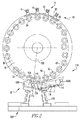
デコレータ用の前処理アセンブリ10及び印刷後処理アセンブリ110が、図1及び2に示されている。例示的な実施形態では、前処理アセンブリ10は、UVインク前処理アセンブリ11である。UVインク前処理アセンブリ11として特定される場合、装置はUVインク前処理アセンブリ11に限定される。更に、例示的な実施形態では、UVインク前処理アセンブリ11は、UVインクを処理するためにコロナを用いるUVインク前処理アセンブリ11である。即ち、前処理アセンブリ10は、ワークピース1を「処理する」ように構成された前処理デバイス12を含む。本明細書では、「処理する」とは、特定の結果をもたらすために、ワークピースに動因又は作用を施すことを意味する。例示的な実施形態では、前処理デバイス12は、幾つかのステーション13を含んでおり、それらステーション13は、例示的な実施形態では、後述するように、イオン発生ステーション90である。前処理アセンブリ10はまた、製品支持アセンブリ20を含んでいる。前処理アセンブリ10は、例示的な実施形態では、他の要素を含んでおり、それらの要素は、例えば、フレームアセンブリ又はハウジングアセンブリと、製品支持アセンブリ20にワークピース1を配置するように構成された送込みアセンブリと、製品支持アセンブリ20からワークピース1を取り出すように構成された取出しアセンブリとであるが、符号は付されていない。本明細書では、「ワークピース」は、作業が施される幾つかの構成要素の1つである。「ワークピース」は、開示されており特許請求された概念の一部ではなく、むしろ、前処理アセンブリ10が幾つかの動作を施す構造体である。例示的な実施形態では、ワークピース1はプラスチックカップ2である。プラスチックカップ2は、底部3と、ほぼ閉じた空間5を画定する側壁4とを含む(図3)。即ち、カップ2、つまり底部3及び側壁4は、本明細書で言う「ほぼ閉じた空間」である、1面を除く全ての面で囲まれた空間5を画定する。カップ側壁4は、内面6及び外面7を有する。カップ2は、一体型の物体である。例示的な実施形態では、カップ側壁4は、底部3から外方へとテーパー状になっている。更に、本明細書では、用語「内面」6及び「外面」7は、適切な場合にはワークピース1でも使用できる。
The pre-processing assembly 10 and the
製品支持アセンブリ20は、移動経路にわたって幾つかのワークピース1を移動させるように構成されている。例示的な実施形態では、図3に示すように、製品支持アセンブリ20は、第一支持アセンブリ22及び幾つかの第二支持アセンブリ24、並びに第一駆動アセンブリ26及び第二駆動アセンブリ28を含む。例えば、第一支持アセンブリ22はコンベアベルトであってよく、第二支持アセンブリ24はコンベアベルトに連結されたブラケットであってもよいが、どちらも図示されていない。例示的な実施形態では、第一支持アセンブリ22はタレットアセンブリ30である。タレットアセンブリ30は、 例示的な実施形態では、ほぼ円形の前面34を有する円盤状の本体32を含む。タレットアセンブリの本体32は、フレームアセンブリに回転可能に連結されており、フレームアセンブリに対して回転するように構成されている。即ち、タレットアセンブリ本体32は回転軸36を有する。更に、タレットアセンブリ本体32は、外半径38と第一の半径40とを有する。第二支持アセンブリ24がタレットアセンブリの本体の前面34に直接連結される実施形態では、第一の半径40は外半径38よりも小さい。図示されていない別の実施形態では、第二支持アセンブリ24は、タレットアセンブリ本体32の径方向側面に連結されており、そこから径方向に延びている。この実施形態では、第一の半径40は外半径38と同じである。タレットアセンブリの本体32は、各第二支持アセンブリ24を第一の半径40にて支持するように構成されている。印刷中、図1に示すように、各第二支持アセンブリ24は、タレットアセンブリの本体の回転軸36に向かって径方向に移動することに留意のこと。更に、図3は、前処理アセンブリ10のみを伴う実施形態を示すことに留意のこと。
The
この例示的な実施形態では、第二支持アセンブリ24は、回転可能なマンドレルアセンブリ50である。各マンドレルアセンブリ50は、第一の端部54及び第二の端部56を有する細長い本体52を含む。各マンドレルアセンブリ本体52、例示的な実施形態では、各マンドレルアセンブリ本体の第一の端部54は、タレットアセンブリ本体32に回転可能に連結されている。図示されている例示的な実施形態では、各マンドレルアセンブリ本体52は、タレットアセンブリ本体の前面34に回転可能に連結されている。この構成では、各マンドレルアセンブリ本体52の長手方向軸は、タレットアセンブリ本体の回転軸36にほぼ平行に延びている。各マンドレルアセンブリ本体52が第一支持アセンブリ22から径方向に延びる図示しない実施形態では、各マンドレルアセンブリ本体52の長手方向軸は、タレットアセンブリ本体の回転軸36に対してほぼ垂直に延びることに留意のこと。更に、図示されている構成では、各マンドレルアセンブリ本体52は、タレットアセンブリ本体の回転軸36にほぼ平行な回転軸58を有する。即ち、各マンドレルアセンブリ本体52の長手方向軸は、その回転軸58でもある。更に、例示的な実施形態では、マンドレルアセンブリ本体の第二の端部56は、ワークピースの内面6に対応している。即ち、この例示的な実施形態では、マンドレルアセンブリ本体の第二の端部56は、テーパー状になっている。
In this exemplary embodiment, the
例示的な実施形態では、第二支持アセンブリ24は、概略的に示されている圧力アセンブリ60を含む。圧力アセンブリ60は、圧力発生アセンブリと幾つかの圧力導管(何れもも図示せず)を含む。圧力導管は、各マンドレルアセンブリ本体52を通って延びており、その表面に、図示していないポートを有する。圧力導管は、圧力発生アセンブリと流体連通している。圧力発生アセンブリは、負圧、即ち吸引を、及び/又は正圧を印加するように構成されている。故に、ワークピース1がマンドレルアセンブリ本体52に配置されると、及び、処理動作中において、圧力発生アセンブリは、ワークピース1をマンドレルアセンブリ本体52上に維持する負圧(吸引)を印加する。処置動作が終了した後、圧力発生アセンブリは、ワークピース1をマンドレルアセンブリ本体52から排出する正圧を印加する。
In an exemplary embodiment, the
第一駆動アセンブリ26は、第一支持アセンブリ22と動作可能に係合し、第一支持アセンブリ22を「一定の速度」、「実質的に一定の速度」、又は「概ね一定の速度」の何れかで動かすように構成されている。本明細書では、「一定の速度」とは、第一駆動アセンブリ26の動作中に、速度の変動なく、第一支持アセンブリ22が設定された維持速度で動くことを意味する。本明細書では、「実質的に一定の速度」とは、第一駆動アセンブリ26の動作中に、最小限度の速度変動で、第一支持アセンブリ22が設定された維持速度で動くことを意味する。本明細書では、「最小限度の速度変動」は、第一支持アセンブリ22が移動する速度が設定速度の約10%までで変動し得ることを意味する。本明細書では、「概ね一定の速度」とは、第一駆動アセンブリ26の動作中に第一支持アセンブリ22が設定された維持速度で移動し、速度が幾分変化することを意味する。本明細書では、「速度が幾分変化」とは、第一支持アセンブリ22が移動する速度が設定速度の約20%までで変動し得ることを意味する。更に、「一定の速度」、「実質的に一定の速度」、又は「概ね一定の速度」の何れも、第一支持アセンブリ22の回転を間欠的に停止することを含まない。即ち、第一支持アセンブリ22が「割送りする」ならば、第一支持アセンブリ22は、「一定の速度」、「実質的に一定の速度」、又は「概ね一定の速度」では動いていない。
The
第一支持アセンブリ22がタレットアセンブリ30である例示的な実施形態では、第一駆動アセンブリ26は、タレットアセンブリ本体32をタレットアセンブリ本体の回転軸36回りで回転させるように構成される。即ち、第一駆動アセンブリ26は、第一支持アセンブリ22に一定の動きをさせるように構成されている。第一駆動アセンブリ26は概略的に示されているが、出力シャフトを備えたモータを含む(何れも図示せず)。出力シャフトは、タレットアセンブリ本体32に連結、直接連結、又は固定されており、モータが作動するとタレットアセンブリ本体32が回転する。例示的な実施形態では、第一駆動アセンブリのモータ26の速度は、以下で説明されるように調整可能である。例示的な実施形態では、第一駆動アセンブリ26は、第一の半径40上の点(以下では縮めて「第一の半径」)が、「速い速度」、「非常に速い速度」、又は「極めて速い速度」の何れかで動くように、タレットアセンブリ本体32をタレットアセンブリ本体の回転軸36回りで回転させるように構成されている。本明細書では、「速い速度」とは、少なくとも33RPMを意味する。本明細書では、「非常に速い速度」は、少なくとも41RPMを意味する。本明細書では、「極めて速い速度」とは、少なくとも50RPMを意味する。
In an exemplary embodiment in which the
上述のように、各マンドレルアセンブリ本体52は、タレットアセンブリ本体32に回転可能に連結されている。更に、第二駆動アセンブリ28は、各第二支持アセンブリ24に、この実施形態では各マンドレルアセンブリ本体52、即ち、各マンドレルアセンブリ本体の第一の端部54に作動可能に係合しており、各第二支持アセンブリ24をその回転軸回りに回転させる。即ち、第二駆動アセンブリ28は、第二支持アセンブリ24に一定の動きをさせるように構成されている。従って、タレットアセンブリ本体32がタレットアセンブリ本体の回転軸36を中心に回転すると、各マンドレルアセンブリ本体52も、それ自身の回転軸58を中心に回転する。例示的な実施形態では、概略的に示されている第二駆動アセンブリ28は、出力シャフト及び駆動ベルト(何れも図示せず)を有するモータを含む。第二駆動アセンブリ28はまた、ガイド、ガイドホイール、及びテンショナのようなベルト駆動に関連する要素も含む(何れも図示せず)。各マンドレルアセンブリ本体の第一の端部54は、駆動ベルトによって動作可能に係合されるように構成されたカップリング(図示せず)を含むか、又は、カップリングとして働くことは理解される。第二駆動アセンブリ28は、以下で説明するように、タレットアセンブリ本体32が、あるイオン化面94付近を移動するのに要する時間内に、各マンドレルアセンブリ本体52を少なくとも1回転(マンドレルアセンブリ本体回転軸58を中心に360度)回転させるように構成される。例示的な実施形態では、第二駆動アセンブリ28の速度は、以下で説明されるように調整可能である。
As described above, each
イオン発生ステーション90は、4つが示されており、隣接する構造体又は隣接する構造体の表面をイオン化するように構成されている。構造体は、例えばワークピース1であるがこれに限定されない。イオン発生ステーション90は、送込みアセンブリと取出しアセンブリの間で第二支持アセンブリ24の移動経路に沿って配置される。例示的な実施形態では、図1に示すように、イオン発生ステーション90は連続して配置されており、互いに直に隣接している。例示的な実施形態では、各イオン発生ステーション90はコロナ放電アセンブリ92である。各イオン発生ステーション90は、イオン化面94を含む。各イオン化面94は、マンドレルアセンブリ本体52の移動経路にほぼ平行に延びている。即ち、マンドレルアセンブリ本体52の移動経路は、タレットアセンブリ本体の回転軸36中心の経路である。例示的な実施形態では、各イオン化面94は、第一の半径40に隣接して、又は直に隣接して配置される。更に、各イオン化面94は、マンドレルアセンブリ本体の第二の端部56の移動経路から「有効距離」だけ離間している。本明細書では、「有効距離」は、特定のイオン化面94がワークピースに必要な量のイオン化を引き起こす距離である。即ち、「有効距離」は、イオン化面94の種類、ワークピースの材料、並びに、第一支持アセンブリ22及び/又は各第二支持アセンブリ24の回転速度によって異なる。
Four
(各第二支持アセンブリ24が回転タレットアセンブリ30に連結される場合のように)第二支持アセンブリ24の移動経路が円状である実施形態では、各イオン化面94は、概ね曲線状であるか又は概ね弓状であって、中心はタレットアセンブリ本体の回転軸36に対応している。更に、上述のようにマンドレルアセンブリ本体の第二の端部56がテーパー状になっている場合、或いは、カップ側壁の外面7などのワークピース外面がテーパー状になっている場合、各イオン化面94は、タレットアセンブリ本体の回転軸36に対して傾斜しており、カップ2がマンドレルアセンブリ本体の第二の端部56に配置されている場合、各イオン化面94は、カップ側壁の外面7とほぼ平行になる。
In the embodiment in which the movement path of the
更に、図示されていない例示的な一実施形態では、第一駆動アセンブリ26及び第二駆動アセンブリ28は、第二駆動アセンブリ28の速度が第一駆動アセンブリ26の関数であるように動作可能に連結されている。故に、この実施形態では、タレットアセンブリ本体32の回転速度と各マンドレルアセンブリ本体52とが関係している。更に、例示的な実施形態では、各マンドレルアセンブリ本体52の回転速度は、タレットアセンブリ本体32に連結されたマンドレルアセンブリ本体52の半径に関係なく、ほぼ同じである。即ち、第一のサイズのカップについては、マンドレルアセンブリ本体52は第一の半径を有しており、異なる第二のサイズのカップについては、マンドレルアセンブリ本体52は異なる第二の半径を有する。マンドレルアセンブリ本体52のサイズに関係なく、マンドレルアセンブリ本体52は、それ自身の軸を中心にしてほぼ同じ速度で回転する。別の例示的な実施形態では、タレットアセンブリ30及びマンドレルアセンブリ本体52の回転速度は、処理されるカップ2のサイズ/形状に応じて変化する。この例示的な実施形態では、第一駆動アセンブリ26及び第二駆動アセンブリ28は、独立に動作可能である。本明細書では、「独立に動作可能」とは、第一駆動アセンブリ26が第一支持アセンブリ22に与える回転速度が、第二駆動アセンブリ28が第二支持アセンブリ24に与える回転速度とは別々であって、数学的な関数で関係しないことを意味する。この実施形態では、各マンドレルアセンブリ本体52のそれ自身の軸回りの回転速度は選択可能であって、マンドレルアセンブリ本体52の半径に関係している。
Further, in one exemplary embodiment not shown, the
前処理アセンブリ10は以下のように動作する。第一駆動アセンブリ26は、タレットアセンブリ30と動作可能に係合しており、タレットアセンブリ本体32を、「一定の速度」、「実質的に一定の速度」、又は「概ね一定の速度」の何れかでタレットアセンブリ本体も回転軸36回りに回転させる。更に、第二駆動アセンブリ28は、各マンドレルアセンブリ本体52に動作可能に係合しており、各マンドレルアセンブリ本体52をそれ自身の回転軸58回りで回転させる。送込みアセンブリ(図示せず)は、タレットアセンブリ本体32に隣接して配置されており、各マンドレルアセンブリ本体52が送込みアセンブリ付近を移動する際に、各マンドレルアセンブリ本体の第二の端部56にカップ2を配置する。例示的な実施形態では、圧力アセンブリ60は負圧を関与させて、カップ2をそれに関連するマンドレルアセンブリ本体の第二の端部56に付勢する。各マンドレルアセンブリ本体52がその移動経路に沿って移動すると、各カップ2は、各イオン発生ステーション90及びそのイオン化面94の側を、その有効距離内で通過する。カップ2がイオン発生ステーション90を通ると、カップ側壁の外面7がイオン化される。次に、各マンドレルアセンブリ本体52は、取出しアセンブリに移動して、それに関連するカップ2がマンドレルアセンブリ本体の第二の端部56から取り外される。このプロセスは、タレットアセンブリ本体32が回転することで繰り返される。
The preprocessing assembly 10 operates as follows. The
タレットアセンブリ本体32及びマンドレルアセンブリ本体52の回転速度は、当技術分野で知られているように、処理される材料、第一の半径40の大きさ、並びに、マンドレルアセンブリ本体52及び/又はそれに配置されたカップ2の半径によって決定される。例示的な実施形態では、しかしながら、タレットアセンブリ本体32は、第一の半径40が「急速な速度」、「迅速な速度」、又は「素早い速度」の何れかと、「一定の速度」、「実質的に一定の速度」、又は「概ね一定の速度」の何れかとで動く。第一支持アセンブリ22は割送りされないので、上記の問題は解決される。
The rotational speeds of the
この構成では、前処理アセンブリ10は、毎分当たり「多数」のワークピース1、毎分当たり「非常に多数」のワークピース1、又は、毎分当たり「極めて多数」のワークピース1の何れかを処理するように構成されている。言い換えると、製品支持アセンブリ20は、毎分当たり「多数」のワークピース1、毎分当たり「非常に多数」のワークピース1、又は、毎分当たり「極めて多数」のワークピース1の何れかに、イオン発生ステーション9付近を有効距離で通過させるように構成されている。本明細書では、毎分当たり「多数」のワークピース1とは、毎分当たり少なくとも800個のワークピースを意味する。本明細書では、毎分当たり「非常に多数」のワークピース1とは、毎分当たり少なくとも1000個のワークピースを意味する。本明細書では、毎分当たり「極めて多数」のワークピース1とは、毎分当たり少なくとも1200個のワークピースを意味する。毎分当たり「多数」のワークピース1、毎分当たり「非常に多数」のワークピース1、又は、毎分当たり「極めて多数」のワークピース1を処理することで、上記の問題が解決する。
In this configuration, the pretreatment assembly 10 is either a "large number" of workpieces 1 per minute, a "very large number" of workpieces 1 per minute, or an "extremely large number" of workpieces 1 per minute. Is configured to handle. In other words, the
更に、本明細書では、ワークピース1を「処理」することは、ワークピースが製品支持アセンブリ20の外側にある場所から(例えば、送込みアセンブリから)移動して、イオン発生ステーション90によって処理されて、製品支持アセンブリ20から排出されることを意味する。更に、例示的な実施形態では、第二支持アセンブリ24は、イオン発生ステーション90にて止まらない。即ち、第一支持アセンブリ22は「一定の速度」、「実質的に一定の速度」、又は「概ね一定の速度」の何れかで動くため、第二支持アセンブリ24はイオン発生ステーション90で止まらない。これにより、上記の問題が解決される。言い換えると、製品支持アセンブリ20は、毎分当たり「多数」のワークピース1、毎分当たり「非常に多数」のワークピース1、又は、毎分当たり「極めて多数」のワークピース1の何れかにイオン発生ステーション90付近を通過させる。本明細書では、「多数のワークピース1にイオン発生ステーション90付近を通過させる」とは、イオン発生ステーション90がワークピース1に作用する状態で、ワークピース1がイオン発生ステーション90付近を移動することであると理解される。即ち、「多数のワークピース1にイオン発生ステーション90付近を通過させる」ということは、例えば、トラック又は他の機械の箱内にあるワークピース1にイオン発生ステーション90付近を移動させることを意味しない。
Further, as used herein, "processing" the workpiece 1 is processed by the
従って、図4に示すように、上記の前処理アセンブリ10を使用してワークピース1を処理する方法は、製品支持アセンブリ、幾つかのイオン発生ステーションを含む前処理アセンブリ10を用意する工程であって、各イオン発生ステーションは製品支持アセンブリに隣接して配置されている、工程を含んでいる(以下、「前処理アセンブリ10を用意する工程1000」と略す)。製品支持アセンブリは、第一支持アセンブリ、第一駆動アセンブリ、幾つかの第二支持アセンブリ、及び第二駆動アセンブリを含む。第一駆動アセンブリは、第一支持アセンブリに動作可能に連結されている。第一駆動アセンブリは、第一支持アセンブリに一定の動きをさせる。各第二支持アセンブリは、幾つかのワークピースを支持するように構成されている。各第二支持アセンブリは、第一支持アセンブリに可動に連結されている。第二駆動アセンブリは、各第二支持アセンブリに動作可能に連結されている。第二駆動アセンブリは、各第二支持アセンブリを選択的に動作させて、幾つかのワークピース1を処理する。幾つかのワークピース1を処理する工程1001には、ワークピース1を第二支持アセンブリ22に配置する工程1002と、第一支持アセンブリ22を概ね一定の速度で移動させる工程1004と、各第二支持アセンブリ24をイオン発生ステーション90付近で移動させる工程1006とが含まれる。
Therefore, as shown in FIG. 4, the method of processing the workpiece 1 using the pretreatment assembly 10 described above is a step of preparing the product support assembly and the pretreatment assembly 10 including some ion generation stations. Each ion generation station includes a step arranged adjacent to the product support assembly (hereinafter, abbreviated as "step 1000 for preparing the pretreatment assembly 10"). Product support assemblies include a first support assembly, a first drive assembly, some second support assemblies, and a second drive assembly. The first drive assembly is operably connected to the first support assembly. The first drive assembly causes the first support assembly to move in a constant manner. Each second support assembly is configured to support several workpieces. Each second support assembly is movably connected to the first support assembly. The second drive assembly is operably coupled to each second support assembly. The second drive assembly selectively operates each second support assembly to process several workpieces 1. The steps 1001 for processing some workpieces include a step 1002 for arranging the workpiece 1 on the
更に、各第二支持アセンブリ24をイオン発生ステーション90付近で移動させる工程1006は、ワークピース1に有効距離でイオン発生ステーション90付近を移動させる工程1010を含む。
Further, the step 1006 of moving each of the
第一支持アセンブリ22を概ね一定の速度で移動させる工程1004は、第一の半径40が急速な速度、迅速な速度、又は素早い速度の何れかで移動するように第一支持アセンブリ22を移動させる工程1020を含む。第一の半径40が急速な速度、迅速な速度、又は素早い速度の何れかで移動するように第一支持アセンブリ22を移動させる工程1020により、上記の問題が解決されることに留意のこと。
Step 1004 of moving the
更に、幾つかのワークピース1を処理する工程1001は、毎分当たり多数のワークピース1、毎分当たり非常に多数のワークピース1、又は毎分当たり極めて多数のワークピース1の何れかを処理する工程1030を含む。毎分当たり多数のワークピース1、毎分当たり非常に多数のワークピース1、又は毎分当たり極めて多数のワークピース1の何れかを処理する工程1030により、上記の問題が解決されることに留意のこと。 Further, step 1001 for processing some workpieces 1 processes either a large number of workpieces 1 per minute, a very large number of workpieces 1 per minute, or a very large number of workpieces 1 per minute. Step 1030 is included. Note that step 1030, which processes either a large number of workpieces 1 per minute, a very large number of workpieces 1 per minute, or a very large number of workpieces 1 per minute, solves the above problem. That thing.
別の例示的な実施形態では、上述の製品支持アセンブリ20は、図1、2、及び5に示される印刷後処理アセンブリ110に組み込まれる。印刷後処理アセンブリ110は、幾つかのステーション113を含む印刷後処理デバイス112も含む。印刷後処理デバイスのステーション113は、製品支持アセンブリ20に隣接して配置される。例示的な実施形態では、印刷後処理アセンブリ110は、UVインク硬化アセンブリ111である。UVインク硬化アセンブリ111として特定される場合、その装置はUVインク硬化アセンブリ111に限定される。即ち、この実施形態では、印刷後処理デバイスのステーション113は、幾つかの紫外線(UV)ランプ120を含む。この実施形態では、製品支持アセンブリ20は、実質的に上記のように組み立てられて動作する。
In another exemplary embodiment, the
この例示的な実施形態では、製品支持アセンブリ20は、ここでも、「一定の速度」、「実質的に一定の速度」、又は「概ね一定の速度」の何れかで移動する。故に、この実施形態では、第二支持アセンブリ24は、どの印刷後処理デバイスのステーション113にも止まらない。即ち、図示のように、以下に説明するように、第二支持アセンブリ24はUVランプ120で止まらない。更に、この実施形態では、第一駆動アセンブリ26は、第一の半径40上の点(以下では縮めて「第一の半径」)が、「速い速度」、「非常に速い速度」、又は「極めて速い速度」の何れかでタレットアセンブリ本体32をタレットアセンブリ本体の回転軸36回りで回転させるように構成されている。本明細書では、「速い速度」とは、少なくとも30RPMを意味する。本明細書では、「非常に速い速度」は、少なくとも40RPMを意味する。本明細書では、「極めて速い速度」とは、少なくとも50RPMを意味する。
In this exemplary embodiment, the
例示的な実施形態では、印刷後処理デバイス112は、多数の紫外線(UV)ランプ120を含む。各UVランプ120は、ハウジング130と、マウント132と、以下「バルブ」134として特定される光発生装置とを含む。本明細書では、「バルブ」は、光を生成する任意のデバイスを意味し、白熱灯の真空バルブに限定されないことは理解される。例示的な実施形態では、各UVランプ120はまた、長手方向軸122を有するビームとしてUVランプバルブ134によって生成された光を概ね又は実質的に反射及び集めるように構成された反射体136を含む。長手方向軸122は概略的に示されており、以下、「光ビーム長手方向軸」122と称される。本明細書では、光ビーム長手方向軸122は、一般に、円錐形又は円筒形のビームの中心に延びている。UVランプバルブ134及びUVランプ反射体136は、UVランプハウジング130に配置される。UVランプハウジング130は、UVランプマウント132に連結、直接連結、又は固定される。例示的な実施形態では、UVランプマウント132は、光ビーム長手方向軸122の向きの調整を可能にするように構成された可動カップリング(図示せず)を含む。更に、例示的な実施形態では、各UVランプ120は、限定ではないがレンズ(図示せず)などの焦点調節デバイス140を含んでいる。
In an exemplary embodiment, the
UVランプ120は、ワークピース1の移動経路に隣接して配置される。即ち、UVランプ120は、第二支持アセンブリ24の移動経路に隣接して配置され、例示的な実施形態では、マンドレルアセンブリ本体の第二の端部56の移動経路に隣接して配置される。更に、例示的な実施形態では、UVランプ120は、「概ね規定された方向」、「実質的に規定された方向」、又は「明確に規定された方向」の何れかでビームUV光を放射するように構成されている。本明細書では、「概ね規定された方向」とは、放射光が一般的な白熱懐中電灯のようなビームに限定されることを意味する。ここで、概ね円錐形の反射器で反射した光はビームのエッジで弱くなって、ビームは一般に散乱する。本明細書では、「実質的に規定された方向」とは、LEDを備えた懐中電灯など(但し、これに限定されない)の焦点制御懐中電灯のビームに放射光が限定されることを意味する。ここで、光線のエッジは最小限の散乱で明確に規定される。本明細書では、「明確に規定された方向」とは、放射光がレーザー又は他の高度に集束した光ビームに類似したビームに限定されることを意味する。ここで、光ビームのエッジは、散乱が無視できるように明確に規定される。
The
例示的な実施形態では、これらUVランプ120は、第一支持アセンブリ22に対して概ね放射状に照らす。即ち、ほぼ円形のタレットアセンブリ本体32では、各光ビームの長手方向軸122は、タレットアセンブリ本体の回転軸36をほぼ通って、又は回転軸36に延びている。更に、UVランプ120は、光ビームの長手方向軸122の仰角「α」の変更を可能にするように構成されている。本明細書では、光ビームの「仰角」は、タレットアセンブリ本体の回転軸36にほぼ垂直な平面に対する光ビームの長手方向軸122の角度である。例えば、タレットアセンブリ本体の前面34がタレットアセンブリ本体の回転軸36にほぼ垂直である実施形態では、「仰角」はタレットアセンブリ本体の前面34である平面に対して測定される。例示的な実施形態では、UVランプ120は、光ビームの長手方向軸122の仰角「α」を約0度乃至12度の間で変更するように構成されている。ワークピース1がテーパー状になっている場合、仰角を変えることで、光ビームの長手方向軸122をワークピース1の外面に対してほぼ又は実質的に垂直に、即ち、ほぼ又は実質的に90度にすることができる。故に、ワークピース1がテーパー状のカップ2である実施形態では、各UVランプの光ビームの長手方向軸122は、ワークピース1の外面、即ちカップ側壁の外面7にほぼ垂直に延びる。
In an exemplary embodiment, these
各UVランプ焦点調節デバイス140は、UVランプ120の焦点距離の調節を可能にするように構成されている。本明細書では、光の「焦点距離」は、光ビームが集中する距離である。上述の問題を解決するために、各UVランプ焦点調節デバイス140は、関連するUVランプ120の焦点距離を「ファジー焦点(fuzzy focus)」に調整するように構成されている。本明細書では、「ファジー焦点」は、概ね各UVランプ120の「臨界焦点(critical focus)」にある焦点である。即ち、各UVランプ120はその「臨界焦点」に設定されていない。別の実施形態では、各UVランプ焦点調節デバイス140は、関連するUVランプ120の焦点距離を「ぼやけた焦点(blurry focus)」に調節するように構成される。本明細書では、「ぼやけた焦点」は、大体各UVランプ120の「臨界焦点」にある焦点である。更に、別の例示的な実施形態では、各UVランプ120はその「臨界焦点」に設定される。
Each UV lamp
更に、例示的な実施形態では、複数のUVランプ120があり、それらUVランプ120は、UV光のフラッド(flood)、即ちUV光フラッドを生成するように構成されている。本明細書では、「UV光のフラッド」、即ち「UV光フラッド」は、複数のUVランプ120が、各UVランプ120の焦点距離が異なるようにUV光のビームを放出することを意味する。この実施形態では、UV光フラッドはUVインクを硬化させるのに十分である。故に、各マンドレルアセンブリ本体の第二の端部56は、UV光フラッドを通る。言い換えると、各マンドレルアセンブリ本体の第二の端部56の移動経路は、UV光フラッドを通る。例示的な実施形態では、各マンドレルアセンブリ本体の第二の端部56の移動経路は、各UV光ビームのファジー焦点を通って延びている。
Further, in an exemplary embodiment, there are a plurality of
更に、例示的な一実施形態では、各マンドレルアセンブリ本体52は、各UVランプ120にほぼ隣接している間、その軸回りに完全に1回転する。即ち、マンドレルアセンブリ本体52は、各UVランプ120についてドエル時間中に1回転する。即ち、各UVランプ120は規定された領域にUV光のビームを放射し、各マンドレルアセンブリ本体52の回転速度は、各UVランプ120のUV光のビーム内にある間に、各マンドレルアセンブリ本体52がその軸回りで1回転するように設定される。別の実施形態では、各マンドレルアセンブリ本体52は、そのマンドレルアセンブリ本体52がUV光のフラッドにある間に、その軸回りで1回転する。別の実施形態では、各マンドレルアセンブリ本体52は、そのマンドレルアセンブリ本体52がUV光のフラッドにある間に、その軸回りで複数回回転する。
Further, in one exemplary embodiment, each
例示的な実施形態では、幾つかのUVランプ120は、第一のUVランプ120A及び第二のUVランプ120Bを含む。例示的な実施形態では、第一のUVランプ120A及び第二のUVランプ120Bは、タレットアセンブリ本体32の回転方向について、可能な限り近接させて配置される。この構成では、第一のUVランプ120Aで開始されたUVインクの重合がまだ行われている間に、第二のUVランプ120Bでのワークピース1の曝露が行われるので、第二のUVランプ120Bによる硬化効果が更に高まる。即ち、この構成では、印刷後処理アセンブリ110は、マルチランプ硬化( multi-lamp cure)を行うように構成されている。本明細書では、「マルチランプ硬化」とは、ワークピース1が複数のUVランプ120の側で一定の動きをしている間に、ワークピース1に配置されたUV硬化インクがそれらUVランプ120によって硬化されることを意味する。更に、本明細書では、「一定の動き」とは、第一支持アセンブリ22が上記で定義した「一定の速度」、「実質的に一定の速度」、又は「概ね一定の速度」の何れかで動くことを意味する。更に、本明細書では、マンドレル本体が自身の軸回りで回転する一方でマンドレル本体の回転軸がUVランプに対して移動しないことによっては、「一定の動き」は達成されない。
In an exemplary embodiment, some
この構成では、印刷後処理アセンブリ110は、毎分当たり「多数」のワークピース1、毎分当たり「非常に多数」のワークピース1、又は、毎分当たり「極めて多数」のワークピース1の何れかを処理するように構成されている。言い換えると、製品支持アセンブリ20は、毎分当たり「多数」のワークピース1、毎分当たり「非常に多数」のワークピース1、又は、毎分当たり「極めて多数」のワークピース1の何れかにUVランプ120付近を通過させるように構成されている。毎分当たり「多数」のワークピース1、毎分当たり「非常に多数」のワークピース1、又は、毎分当たり「極めて多数」のワークピース1を処理することにより、上記の問題が解決する。
In this configuration, the
更に、本明細書では、印刷後処理アセンブリ110のコンテクストにおいて、ワークピース1を「処理」することは、ワークピースが製品支持アセンブリ20の外側にある場所から(例えば、送込みアセンブリから)移動して、UVランプ120によって処理されて、製品支持アセンブリ20から排出されることを意味する。更に、例示的な実施形態では、第二支持アセンブリ24はどのUVランプ120にも止まらない。即ち、第一支持アセンブリ22は、「一定の速度」、「実質的に一定の速度」、又は「概ね一定の速度」の何れかで移動することから、どのUVランプ120にも第二支持アセンブリ24は止まらない。これによって、上記の問題が解決する。言い換えると、製品支持アセンブリ20は、毎分当たり「多数」のワークピース1、毎分当たり「非常に多数」のワークピース1、又は、毎分当たり「極めて多数」のワークピース1の何れかにUVランプ120付近を通過させるように構成されている。本明細書では、「幾つかのワークピース1にUVランプ120付近を通過させる」とは、ワークピース1がUVランプ120付近を移動して、UVランプ120がワークピース1を処理することを意味する。つまり、「幾つかのワークピース1にUVランプ120付近を通過させる」ということは、例えば、トラック又は他の機械の箱内にあるワークピース1にUVランプ120付近移動させることを意味しない。
Further, as used herein, in the context of the
従って、図6に示すように、上述の印刷後処理アセンブリ110を使用してワークピース1を処理する方法は、製品支持アセンブリ及び幾つかのUVランプ120を含む印刷後処理アセンブリ110を用意する工程2000(以下、「印刷後処理アセンブリ110を用意する工程2000」と略す)と、幾つかのワークピースの後処理を行う工程2001とを含んでいる。各UVランプ120は、製品支持アセンブリに隣接して配置されており、製品支持アセンブリは、 第一支持アセンブリ、第一駆動アセンブリ、幾つかの第二支持アセンブリ、及び第二駆動アセンブリを含む。第一駆動アセンブリは、第一支持アセンブリに動作可能に連結されて、第一支持アセンブリに一定の動きをさせる。各第二支持アセンブリは幾つかのワークピースを支持するように構成されており、第一支持アセンブリに可動に連結されている。第二駆動アセンブリは、 各第二支持アセンブリに動作可能に連結されており、各第二支持アセンブリを選択的に動作させる。幾つかのワークピース1を後処理する工程2001は、ワークピース1を第二支持アセンブリ22に配置する工程2002と、第一支持アセンブリ22を概ね一定の速度で移動させる工程2004と、各第二支持アセンブリ24をUVランプ120付近で移動させる工程2006とを含む。
Therefore, as shown in FIG. 6, the method of processing the workpiece 1 using the
更に、第一支持アセンブリ22をほぼ一定の速度で移動させる工程2004は、第一支持アセンブリ22上の第一の半径が、速い速度、非常に速い速度、又は非常に速い速度の何れかで移動するように第一支持アセンブリ22を動かす工程2020を含む。
Further, in step 2004 of moving the
更に、 幾つかのワークピース1を後処理する工程2001は、毎分当たり多数のワークピース1、毎分当たり非常に多数のワークピース1、又は毎分当たり非常に多数のワークピース1の何れかを処理する工程を含む。 Further, the step 2001 of post-processing some workpieces 1 is either a large number of workpieces 1 per minute, a very large number of workpieces 1 per minute, or a very large number of workpieces 1 per minute. Includes the process of processing.
本発明の特定の実施形態について詳細に説明したが、当業者であれば、それらの詳細に対する様々な修正や代替を、本開示の教示全体に鑑み開発することができると認識されるであろう。従って、開示される特定の構成は、単に例示であることを意図しており、添付の特許請求の範囲及びその全ての均等物の全範囲を、提供される発明の範囲に関して限定するものではない。 Although specific embodiments of the present invention have been described in detail, one of ordinary skill in the art will recognize that various modifications and alternatives to those details can be developed in light of the teachings of the present disclosure. .. Accordingly, the particular configurations disclosed are intended to be merely exemplary and do not limit the scope of the appended claims and all their equivalents with respect to the scope of the invention provided. ..
Claims (14)
前記前処理アセンブリ(10)は、幾つかのワークピース(1)を処理するように構成されており、
前記前処理アセンブリ(10)は、幾つかのイオン発生ステーション(90)を含んでおり、
前記製品支持アセンブリ(20)は、
第一支持アセンブリ(22)と、
第一駆動アセンブリ(26)と、
幾つかの第二支持アセンブリ(24)と、
第二駆動アセンブリ(28)と、
を備えており、
前記第一駆動アセンブリ(26)は、前記第一支持アセンブリ(22)に動作可能に連結されており、
前記第一駆動アセンブリ(26)は、前記第一支持アセンブリ(22)に一定の動きをさせ、
各第二支持アセンブリ(24)は、幾つかのワークピース(1)を支持するように構成されており、
各第二支持アセンブリ(24)は、前記第一支持アセンブリ(22)に可動に連結されており、
前記第二駆動アセンブリ(28)は、各第二支持アセンブリ(24)に動作可能に連結されており、
前記第二駆動アセンブリ(28)は、各第二支持アセンブリ(24)を選択的に動かし、
どの第二支持アセンブリ(24)もイオン発生ステーション(90)で止まらない、
製品支持アセンブリ。 Product support assembly (20) for pretreatment assembly (10)
The pretreatment assembly (10) is configured to process several workpieces (1).
The pretreatment assembly (10) includes several ion generation stations (90).
The product support assembly (20) is
First support assembly (22) and
First drive assembly (26) and
With some second support assemblies (24),
Second drive assembly (28) and
Is equipped with
The first drive assembly (26) is operably connected to the first support assembly (22).
The first drive assembly (26) causes the first support assembly (22) to make a constant movement.
Each second support assembly (24) is configured to support several workpieces (1).
Each second support assembly (24) is movably connected to the first support assembly (22).
The second drive assembly (28) is operably connected to each second support assembly (24).
It said second drive assembly (28) is selectively move each second support assembly (24),
None of the second support assemblies (24) stop at the ion generation station (90),
Product support assembly.
前記タレットアセンブリ(30)は、各第二支持アセンブリ(24)を第一の半径(40)にて支持するように構成された本体(32)を含んでおり、
前記タレットアセンブリの本体(32)は回転軸(36)を有しており、
各第二支持アセンブリ(24)は、前記第一の半径(40)にて前記タレットアセンブリ(30)に連結されており、
前記第一駆動アセンブリ(26)は、前記第一の半径(40)が速い速度、非常に速い速度、又は極めて速い速度の何れかで移動するように前記タレットアセンブリの本体(32)を回転させるように構成されている、請求項1に記載の製品支持アセンブリ。 The first support assembly (22) is a turret assembly (30).
The turret assembly (30) includes a body (32) configured to support each second support assembly (24) with a first radius (40).
The body (32) of the turret assembly has a rotating shaft (36).
Each second support assembly (24) is connected to the turret assembly (30) by the first radius (40).
The first drive assembly (26) rotates the body (32) of the turret assembly so that the first radius (40) moves at either a fast speed, a very fast speed, or a very fast speed. The product support assembly according to claim 1, which is configured in such a manner.
各マンドレルアセンブリ(50)は、第一の端部(54)及び第二の端部(56)を有する細長い本体(52)を含んでおり、
各マンドレルアセンブリ本体(52)は、前記タレットアセンブリの本体(32)に回転可能に連結されている、請求項2に記載の製品支持アセンブリ。 Each second support assembly (24) is a mandrel assembly (50).
Each mandrel assembly (50) includes an elongated body (52) having a first end (54) and a second end (56).
The product support assembly according to claim 2, wherein each mandrel assembly body (52) is rotatably connected to the body (32) of the turret assembly.
各マンドレルアセンブリの本体の第二の端部(56)の移動経路は、各イオン化面(94)から有効距離に配置される、請求項3に記載の製品支持アセンブリ。 Each ion generation station (90) includes an ionization plane (94), each ionization plane (94) has a width, and each ion surface (94) is the first radius of the body of the turret assembly. Arranged adjacent to (40), each ionization plane (94) extends substantially parallel to the movement path of the body (52) of the mandrel assembly.
The product support assembly according to claim 3, wherein the movement path of the second end (56) of the body of each mandrel assembly is located at an effective distance from each ionization plane (94).
前記第二駆動アセンブリ(28)は、各マンドレルアセンブリンの本体(52)が各イオン化面(94)付近を移動すると、各マンドレルアセンブリの本体(52)を実質的に一回転させるように構成されている、請求項4に記載の製品支持アセンブリ。 The first drive assembly (26) has a first rotational speed.
The second drive assembly (28) is configured such that when the body (52) of each mandrel assembly moves near each ionization surface (94), the body (52) of each mandrel assembly is substantially rotated once. The product support assembly according to claim 4.
幾つかの前記イオン発生ステーション(90)と、
を備える前処理アセンブリ(10)であって、
各イオン発生ステーション(90)は、前記製品支持アセンブリ(20)に隣接して配置されている、前処理アセンブリ。 The product support assembly (20) according to any one of claims 1 to 9.
With some of the ion generation stations (90),
A pretreatment assembly (10) comprising:
Each ion generation station (90) is a pretreatment assembly located adjacent to the product support assembly (20).
製品支持アセンブリと、幾つかのイオン発生ステーションを含む前処理アセンブリ(10)を用意する工程(1000)であって、
各イオン発生ステーションは、前記製品支持アセンブリに隣接して配置され、
前記製品支持アセンブリは、第一支持アセンブリ(22)、第一駆動アセンブリ、幾つかの第二支持アセンブリ(24)、及び第二駆動アセンブリを含んでおり、
前記第一駆動アセンブリは、前記第一支持アセンブリ(22)に動作可能に連結されており、
前記第一駆動アセンブリは、前記第一支持アセンブリ(22)に一定の動きをさせ、
各第二支持アセンブリ(24)は、幾つかのワークピースを支持するように構成されており、
各第二支持アセンブリ(24)は、前記第一支持アセンブリ(22)に可動に連結されており、
前記第二駆動アセンブリは、各第二支持アセンブリ(24)に動作可能に連結されており、
前記第二駆動アセンブリは、各第二支持アセンブリ(24)を選択的に動かす、
工程(1000)と、
幾つかのワークピース(1)を処理する工程(1001)と、
を含んでおり、
幾つかのワークピース(1)を処理する工程(1001)は、
第二支持アセンブリ(24)にワークピース(1)を配置する工程(1002)と、
前記第一支持アセンブリ(22)をほぼ一定の速度で移動させる工程(1004)と、
各第二支持アセンブリ(24)に前記幾つかのイオン発生ステーション(90)付近を移動させる工程(1006)と、
を含んでおり、
どの第二支持アセンブリ(24)もイオン発生ステーション(90)で止まらない、
方法。 In the method of processing some workpieces (1)
A step (1000) of preparing a product support assembly and a pretreatment assembly (10) containing several ion generation stations.
Each ion generation station is located adjacent to the product support assembly.
The product support assembly includes a first support assembly (22) , a first drive assembly, some second support assemblies (24) , and a second drive assembly.
The first drive assembly is operably coupled to the first support assembly (22).
The first drive assembly causes the first support assembly (22) to make a constant movement.
Each second support assembly (24) is configured to support several workpieces.
Each second support assembly (24) is movably connected to the first support assembly (22).
The second drive assembly is operably coupled to each second support assembly (24).
The second drive assembly selectively moves each second support assembly (24).
Process (1000) and
The step (1001) of processing some workpieces (1) and
Includes
The step (1001) of processing some workpieces (1) is
The step (1002) of arranging the workpiece (1) on the second support assembly (24),
The step (1004) of moving the first support assembly (22) at a substantially constant speed, and
A step (1006) of moving the vicinity of some of the ion generation stations (90) to each second support assembly (24),
A and Nde including,
None of the second support assemblies (24) stop at the ion generation station (90),
Method.
Priority Applications (1)
| Application Number | Priority Date | Filing Date | Title |
|---|---|---|---|
| JP2021150019A JP7374966B2 (en) | 2017-07-14 | 2021-09-15 | Pretreatment assembly and product support assembly for processing workpieces |
Applications Claiming Priority (3)
| Application Number | Priority Date | Filing Date | Title |
|---|---|---|---|
| US15/650,005 | 2017-07-14 | ||
| US15/650,005 US10913995B2 (en) | 2017-07-14 | 2017-07-14 | Pretreatment assembly and method for treating work pieces |
| PCT/US2018/041554 WO2019014298A1 (en) | 2017-07-14 | 2018-07-11 | Pretreatment assembly and method for treating work pieces |
Related Child Applications (1)
| Application Number | Title | Priority Date | Filing Date |
|---|---|---|---|
| JP2021150019A Division JP7374966B2 (en) | 2017-07-14 | 2021-09-15 | Pretreatment assembly and product support assembly for processing workpieces |
Publications (3)
| Publication Number | Publication Date |
|---|---|
| JP2020527451A JP2020527451A (en) | 2020-09-10 |
| JP2020527451A5 JP2020527451A5 (en) | 2020-10-22 |
| JP6946543B2 true JP6946543B2 (en) | 2021-10-06 |
Family
ID=64998859
Family Applications (2)
| Application Number | Title | Priority Date | Filing Date |
|---|---|---|---|
| JP2020501146A Active JP6946543B2 (en) | 2017-07-14 | 2018-07-11 | Pretreatment assembly and method for processing workpieces |
| JP2021150019A Active JP7374966B2 (en) | 2017-07-14 | 2021-09-15 | Pretreatment assembly and product support assembly for processing workpieces |
Family Applications After (1)
| Application Number | Title | Priority Date | Filing Date |
|---|---|---|---|
| JP2021150019A Active JP7374966B2 (en) | 2017-07-14 | 2021-09-15 | Pretreatment assembly and product support assembly for processing workpieces |
Country Status (5)
| Country | Link |
|---|---|
| US (1) | US10913995B2 (en) |
| EP (1) | EP3652589A4 (en) |
| JP (2) | JP6946543B2 (en) |
| CN (1) | CN111133387B (en) |
| WO (1) | WO2019014298A1 (en) |
Families Citing this family (1)
| Publication number | Priority date | Publication date | Assignee | Title |
|---|---|---|---|---|
| CN115386842A (en) * | 2022-09-20 | 2022-11-25 | 湖南千山制药机械股份有限公司 | Plastic ampoule vacuum outer plating module and integrated forming machine |
Family Cites Families (40)
| Publication number | Priority date | Publication date | Assignee | Title |
|---|---|---|---|---|
| US2330880A (en) * | 1940-07-16 | 1943-10-05 | Crown Cork & Seal Co | Coating machine |
| GB1316271A (en) | 1969-05-13 | 1973-05-09 | Jackson Developments Ltd Max | Multi-colour printing machine for cylindrical and frusto-conical objects |
| DE2110929A1 (en) * | 1971-03-08 | 1972-10-12 | Softal Elektronik Gmbh | Method and device for drying oxidatively drying printing inks |
| US3802380A (en) * | 1971-08-26 | 1974-04-09 | Sangamo Electric Co | Apparatus for applying an insulating coating on capacitor cans |
| US4543883A (en) | 1978-06-19 | 1985-10-01 | Sun Chemical Corporation | Apparatus for printing frustoconical articles |
| JPS5966429A (en) * | 1982-10-08 | 1984-04-14 | Fuji Kikai Kogyo Kk | Apparatus for treating surface of synthetic resin material to be printed |
| JPS5964936U (en) * | 1982-10-25 | 1984-04-28 | 日本曲面印刷機株式会社 | Surface treatment equipment for synthetic resin cylindrical molded products using corona discharge |
| US4535549A (en) * | 1983-11-02 | 1985-08-20 | American Screen Printing Equipment Company | Curing apparatus |
| JPS617543U (en) * | 1984-06-15 | 1986-01-17 | 株式会社日本曲面印刷研究所 | Continuous surface treatment equipment for synthetic resin moldings using corona discharge |
| US4781112A (en) * | 1987-05-04 | 1988-11-01 | American Production Machine Company | Apparatus for printing hollow containers |
| US5337659A (en) | 1993-02-22 | 1994-08-16 | Sequa Corporation | Apparatus and method utilizing continuous motion offset and direct printing techniques for decorating cylindrical containers |
| JP3077542B2 (en) * | 1995-01-13 | 2000-08-14 | 東洋製罐株式会社 | Printed plastic molding and method for producing the same |
| JPH08315956A (en) * | 1995-05-18 | 1996-11-29 | Kasuga Denki Kk | Corona discharge treatment method of vessel, and device therefor |
| US5970865A (en) | 1997-02-26 | 1999-10-26 | Mitsubishi Materials Corporation | Apparatus and method for printing multi-color images onto cylindrical body |
| US5989644A (en) * | 1998-06-12 | 1999-11-23 | Adac Plastics, Inc. | Painting apparatus and method |
| FR2782376B1 (en) * | 1998-08-13 | 2000-11-10 | Dubuit Mach | ULTRAVIOLET RADIATION DRYING OVEN, AND PRINTING MACHINE COMPRISING AT LEAST ONE SUCH A DRYING OVEN |
| US6578474B1 (en) * | 1998-11-25 | 2003-06-17 | Surfcoat Co., Ltd. | Printing or coating method and printing or coating device |
| JP2001130529A (en) * | 1999-11-09 | 2001-05-15 | Risu Pack Co Ltd | Cup container and its manufacturing method |
| IT1315621B1 (en) * | 2000-03-21 | 2003-03-14 | Tecno Italia S R L | MACHINE AND METHOD FOR PRINTING ON CONTAINERS. |
| US6245386B1 (en) * | 2000-04-26 | 2001-06-12 | Callaway Golf Company | Method and system for finishing a golf ball |
| US6491755B1 (en) * | 2000-09-11 | 2002-12-10 | Adac Plastics, Inc. | Painting apparatus with compound rack |
| US6769357B1 (en) * | 2003-06-05 | 2004-08-03 | Sequa Can Machinery, Inc. | Digital can decorating apparatus |
| FR2856338B1 (en) | 2003-06-23 | 2005-09-16 | Dubuit Mach | MACHINE FOR PRINTING OBJECTS WITH IMPROVED PROTECTION FROM ULTRAVIOLET RADIATION. |
| ITRE20060016A1 (en) | 2006-02-10 | 2007-08-11 | Omso Officina Macchine Per Stampa Su Oggetti | SCREEN PRINTING MACHINE FOR CYLINDRICAL OBJECTS |
| US7589474B2 (en) * | 2006-12-06 | 2009-09-15 | City University Of Hong Kong | Ion source with upstream inner magnetic pole piece |
| DE102007005340B4 (en) * | 2007-02-02 | 2009-12-03 | Polytype Converting S.A. | Printing method and apparatus for printing on hollow bodies |
| BRPI0810301B1 (en) | 2007-08-03 | 2020-09-01 | Khs Maschinen Und Anlagenbau Ag (Khs Ag) | DEVICE AND STAMPING PROCESS ON CONTAINERS |
| DE102009013477B4 (en) * | 2009-03-19 | 2012-01-12 | Khs Gmbh | Printing device for printing on bottles or similar containers |
| DE102009020702B4 (en) | 2009-05-11 | 2011-09-15 | Khs Gmbh | Printing system for printing on bottles or similar containers and printing device or machine with such a printing system |
| IT1394325B1 (en) | 2009-06-15 | 2012-06-06 | Omso Officina Macchine Per Stampa Su Oggetti Societa Per Azioni | ROTATING GIOSTRA FOR ROTARY-TYPE PRINTING MACHINE |
| EP2474419A4 (en) | 2009-08-31 | 2013-09-04 | Mimaki Eng Kk | Three-dimensional inkjet printer |
| EP3434490A1 (en) * | 2010-07-23 | 2019-01-30 | Plastipak Packaging Inc. | Rotary system and method for printing containers |
| FR2985683B1 (en) * | 2012-01-16 | 2014-02-28 | Jean Luc Perret | PRINTING MACHINE ON THREE-DIMENSIONAL ARTICLES AND PRINTING METHOD |
| EP2754556A1 (en) * | 2013-01-11 | 2014-07-16 | Crown Packaging Technology Inc | In-feed system and method for supplying can bodies to a decorator |
| DE102013005048A1 (en) * | 2013-03-22 | 2014-09-25 | Optipack Gmbh | Coating device and coating method |
| DE102013214980A1 (en) | 2013-07-31 | 2015-02-05 | Krones Ag | Printing machine with printhead control |
| DE102013217659A1 (en) | 2013-09-04 | 2015-03-05 | Krones Ag | Container treatment machine for printing on containers |
| EP3055137B1 (en) * | 2013-10-08 | 2017-12-06 | Till GmbH | Intermittently operating printing machine |
| JP6903010B2 (en) * | 2015-03-04 | 2021-07-14 | ストール マシーナリ カンパニー, エルエルシーStolle Machinery Company, LLC | Digital press and method |
| US9327493B1 (en) * | 2015-03-04 | 2016-05-03 | Stolle Machinery Company, Llc | Digital printing machine and method |
-
2017
- 2017-07-14 US US15/650,005 patent/US10913995B2/en active Active
-
2018
- 2018-07-11 WO PCT/US2018/041554 patent/WO2019014298A1/en unknown
- 2018-07-11 JP JP2020501146A patent/JP6946543B2/en active Active
- 2018-07-11 CN CN201880046830.4A patent/CN111133387B/en active Active
- 2018-07-11 EP EP18832118.6A patent/EP3652589A4/en active Pending
-
2021
- 2021-09-15 JP JP2021150019A patent/JP7374966B2/en active Active
Also Published As
| Publication number | Publication date |
|---|---|
| JP7374966B2 (en) | 2023-11-07 |
| CN111133387A (en) | 2020-05-08 |
| WO2019014298A1 (en) | 2019-01-17 |
| JP2020527451A (en) | 2020-09-10 |
| US10913995B2 (en) | 2021-02-09 |
| JP2022002844A (en) | 2022-01-11 |
| EP3652589A4 (en) | 2021-04-14 |
| US20190017160A1 (en) | 2019-01-17 |
| CN111133387B (en) | 2023-09-01 |
| EP3652589A1 (en) | 2020-05-20 |
Similar Documents
| Publication | Publication Date | Title |
|---|---|---|
| US6371631B1 (en) | Radiation source for irradiating the inner walls of long hollow cavities | |
| JP7374966B2 (en) | Pretreatment assembly and product support assembly for processing workpieces | |
| JP7322229B2 (en) | PRODUCT SUPPORT ASSEMBLY, PRE-PROCESSING ASSEMBLY, POST PRINTING PROCESSING ASSEMBLY AND METHOD FOR PROCESSING WORKPIECE | |
| GB2592168A (en) | Systems and methods for post additive manufacturing processing | |
| JP4965609B2 (en) | Wide-area atmospheric pressure plasma jet system | |
| WO2013069207A1 (en) | Container processing device | |
| US7235147B2 (en) | Method of forming tire component member | |
| EP1981712B1 (en) | A silk screen printing machine for cylindrical objects | |
| JP7331017B2 (en) | drive assembly | |
| US20180141164A1 (en) | Coating removal method | |
| RU2010138281A (en) | METHOD AND DEVICE AT LEAST FOR PARTIAL REMOVAL OF COATING, AND ALSO INSTALLATION FOR SURFACE TREATMENT | |
| SE530512C2 (en) | Automatic centering method for annular workpiece involves arranging spaced apart contact part and rotationally driven wheel so friction force results in force component acting on workpiece to move outward from center of rotating surface | |
| JP5321053B2 (en) | Can manufacturing apparatus and can manufacturing method | |
| US9583309B1 (en) | Selective area implant of a workpiece | |
| US11254106B2 (en) | Machining system and machining method | |
| SE1000998A1 (en) | Device for machining sleeves | |
| JP2020527451A5 (en) | ||
| CN104272448A (en) | Device for removing a coating from a substrate and method | |
| JP5749051B2 (en) | Transfer method | |
| TWM581582U (en) | Air floating electrostatic clapping plate device | |
| SE530513C2 (en) | Automatic centering method for annular workpiece involves arranging spaced apart contact part and rotationally driven wheel so friction force results in force component acting on workpiece to move outward from center of rotating surface | |
| JP2020001279A (en) | Pattern transfer device | |
| CN105436965A (en) | Flexible machining device with pneumatic motor | |
| WO2012133102A1 (en) | Polymerizable monomer-condensing device | |
| JP2012240021A (en) | Ultraviolet irradiation device |
Legal Events
| Date | Code | Title | Description |
|---|---|---|---|
| A521 | Request for written amendment filed |
Free format text: JAPANESE INTERMEDIATE CODE: A523 Effective date: 20200722 |
|
| A521 | Request for written amendment filed |
Free format text: JAPANESE INTERMEDIATE CODE: A523 Effective date: 20200813 |
|
| A621 | Written request for application examination |
Free format text: JAPANESE INTERMEDIATE CODE: A621 Effective date: 20200813 |
|
| A977 | Report on retrieval |
Free format text: JAPANESE INTERMEDIATE CODE: A971007 Effective date: 20210422 |
|
| A131 | Notification of reasons for refusal |
Free format text: JAPANESE INTERMEDIATE CODE: A131 Effective date: 20210427 |
|
| A521 | Request for written amendment filed |
Free format text: JAPANESE INTERMEDIATE CODE: A523 Effective date: 20210716 |
|
| TRDD | Decision of grant or rejection written | ||
| A01 | Written decision to grant a patent or to grant a registration (utility model) |
Free format text: JAPANESE INTERMEDIATE CODE: A01 Effective date: 20210824 |
|
| A61 | First payment of annual fees (during grant procedure) |
Free format text: JAPANESE INTERMEDIATE CODE: A61 Effective date: 20210915 |
|
| R150 | Certificate of patent or registration of utility model |
Ref document number: 6946543 Country of ref document: JP Free format text: JAPANESE INTERMEDIATE CODE: R150 |