JP6945834B2 - Pachinko machine - Google Patents
Pachinko machine Download PDFInfo
- Publication number
- JP6945834B2 JP6945834B2 JP2017045039A JP2017045039A JP6945834B2 JP 6945834 B2 JP6945834 B2 JP 6945834B2 JP 2017045039 A JP2017045039 A JP 2017045039A JP 2017045039 A JP2017045039 A JP 2017045039A JP 6945834 B2 JP6945834 B2 JP 6945834B2
- Authority
- JP
- Japan
- Prior art keywords
- game
- special
- character
- symbol
- light
- Prior art date
- Legal status (The legal status is an assumption and is not a legal conclusion. Google has not performed a legal analysis and makes no representation as to the accuracy of the status listed.)
- Active
Links
Images


Description
本発明は、遊技盤に形成された遊技領域に向けて遊技球を発射することによって遊技を行う遊技機(パチンコ機)に関する。 The present invention relates to a gaming machine (pachinko machine) that plays a game by firing a gaming ball toward a gaming area formed on a gaming board.
遊技盤に形成された遊技領域に向けて遊技球を発射することによって遊技を行う遊技機が知られている。このような遊技機では、遊技の進行過程において種々の演出を行うことが一般的である。例えば、液晶表示器を設けて、該液晶表示器に種々の画像を表示する演出が実行される。 A gaming machine that plays a game by firing a gaming ball toward a gaming area formed on a gaming board is known. In such a gaming machine, it is common to perform various effects in the process of proceeding with the game. For example, a liquid crystal display is provided, and an effect of displaying various images on the liquid crystal display is executed.
近年では、演出効果(視覚効果)を更に高めるために、移動可能に設けられた役物を移動させる演出が一般的になりつつあり、なかには、該役物を発光させる演出を行う遊技機も存在する。例えば、特許文献1には、バナナを模した役物を揺動動作させると共に、該役物の内部にLEDを設けて発光させる演出について開示されている。
In recent years, in order to further enhance the effect (visual effect), it is becoming common to move a movable accessory, and there is also a gaming machine that makes the accessory emit light. do. For example,
しかしながら、上述したような単にLEDを発光させる演出は、一般的な遊技者にとって周知の技術であり、遊技興趣を十分に高めることができないという問題があった。 However, the effect of simply emitting the LED as described above is a well-known technique for general players, and there is a problem that the game entertainment cannot be sufficiently enhanced.
本発明は、上述した課題を解決するためになされたものであり、遊技興趣をより高める演出を実行可能な遊技機を提供することを目的とする。 The present invention has been made to solve the above-mentioned problems, and an object of the present invention is to provide a gaming machine capable of performing an effect that further enhances the interest of gaming.
上述した課題の少なくとも一部を解決するために、本発明の遊技機は次の構成を採用した。すなわち、
遊技盤に形成された遊技領域に向けて遊技球を発射することによって遊技を行う遊技機であって、
表側に文字が表示された文字ユニットと、
前記文字ユニットの裏側に位置する発光体と、
を備え、
前記文字ユニットには、表側からみて当該文字ユニットから離れる方向に前記発光体の光を透過させる透過部位が複数設けられており、
前記文字ユニットとして、第1文字ユニットと第2文字ユニットとを備えており、
前記第1文字ユニットの前記透過部位の一部と、前記第2文字ユニットの前記透過部位の一部とは互いに対向しており、
前記互いに対向している前記透過部位の間には、当該互いに対向している前記透過部位を透過する前記発光体の光を乱反射させる乱反射部が設けられている
ことを特徴とする。
In order to solve at least a part of the above-mentioned problems, the gaming machine of the present invention adopts the following configuration. That is,
A gaming machine that plays a game by firing a gaming ball toward a gaming area formed on a gaming board.
A character unit with characters displayed on the front side and
A light emitter located on the back side of the character unit and
With
The character unit is provided with a plurality of transmission portions for transmitting the light of the light emitting body in a direction away from the character unit when viewed from the front side .
The character unit includes a first character unit and a second character unit.
A part of the transparent part of the first character unit and a part of the transparent part of the second character unit face each other.
Between the transmitting portions facing each other, a diffused reflecting portion for diffusely reflecting the light of the light emitting body transmitted through the transmitting portions facing each other is provided .
本発明によれば、遊技興趣をより高める演出を行うことができる。 According to the present invention, it is possible to perform an effect that further enhances the entertainment of the game.
上述した本発明の内容を明確にするために、本発明を「セブン機」や「デジパチ」と呼ばれるタイプのパチンコ機(遊技機)に適用した実施例について説明する。尚、実施例においては、特に断りがない限りは、パチンコ機正面に向かって右側を「右」と表現し、左側を「左」と表現する。 In order to clarify the contents of the present invention described above, an example in which the present invention is applied to a type of pachinko machine (game machine) called "seven machine" or "digipachi" will be described. In the embodiment, unless otherwise specified, the right side is expressed as "right" and the left side is expressed as "left" when facing the front of the pachinko machine.
また、以下の実施例は次のような順序に従って説明する。
A.パチンコ機の装置構成:
A−1.装置前面側の構成:
A−2.遊技盤の構成:
A−3.制御回路の構成:
B.遊技の内容:
C.遊技制御処理:
D.演出制御処理:
E.役物上昇演出:
E−1.役物上昇演出の概要:
E−2.移動役物70:
Further, the following examples will be described in the following order.
A. Pachinko machine equipment configuration:
A-1. Configuration on the front side of the device:
A-2. Game board composition:
A-3. Control circuit configuration:
B. Game content:
C. Game control processing:
D. Production control processing:
E. Character rise production:
E-1. Outline of the character rising production:
E-2. Mobile character 70:
A.パチンコ機の装置構成 :
A−1.装置前面側の構成 :
図1は、本実施例のパチンコ機1の正面図である。図1に示すように、パチンコ機1の前面部には、前面枠4が設けられている。前面枠4は、一端(図1における左側)が中枠3に対して回動可能に軸支されている。中枠3の前面側には遊技盤20(図2参照)が着脱可能に取り付けられており、前面枠4が中枠3に対してパチンコ機1前方側に回動(開放)されると、遊技盤20が露出された状態となる。中枠3は、一端(図1における左側)が本体枠2に対して回動可能に軸支されている。本体枠2は、木製の板状部材を組み立てて構成された略長方形の枠体であり、パチンコ機1の外枠を形成している。
A. Pachinko machine equipment configuration:
A-1. Configuration on the front side of the device:
FIG. 1 is a front view of the
前面枠4の略中央部には窓部4aが形成されており、この窓部4aにはガラス板等の透明板4bが嵌め込まれている。遊技者は、窓部4a(透明板4b)を通して奥側に配置される遊技盤20の遊技領域を視認可能である。また、前面枠4における窓部4aの右下方には、小窓部4cが形成されており、この小窓部4cには合成樹脂板等の透明板4dが嵌め込まれている。遊技者は、小窓部4c(透明板4d)を通して奥側に配置された遊技盤20のセグメント表示部を視認可能である。詳しくは後述するが、セグメント表示部とは、複数のLEDの組合せによって遊技に係る情報を表示する表示部である。
A
前面枠4における窓部4aの上方には上部ランプ5aが設けられ、窓部4aの周縁部における右部には右サイドランプ5bが設けられ、窓部4aの周縁部における左部には左サイドランプ5cが設けられている。また、前面枠4における窓部4aの左右上方には上部スピーカー6aが設けられており、本体枠2の下部の前面には下部スピーカー6bが設けられている。これらの上部ランプ5a、右サイドランプ5b、左サイドランプ5c、上部スピーカー6a、下部スピーカー6bは、遊技上の演出効果を高めるために駆動される。
An
前面枠4における窓部4aの下方には、上皿部7が設けられている。上皿部7には、カードユニット242(図3参照)を介して貸し出される遊技球や、パチンコ機1から払い出される遊技球が貯留される。また、上皿部7の下方には下皿部8が設けられており、上皿部7の容量を超えて貸し出された遊技球や、上皿部7の容量を超えて払い出された遊技球が貯留される。
An
前面枠4における下皿部8の右方には、発射ハンドル9が設けられている。発射ハンドル9の回転軸は、発射ハンドル9の奥側に搭載された発射装置ユニット261(図3参照)に接続されている。この発射装置ユニット261には、上皿部7に貯留された遊技球が供給される。遊技者が発射ハンドル9を回転させると、その回転が発射装置ユニット261に伝達され、発射装置ユニット261に内蔵された発射モーターが回転して、回転角度に応じた強さで遊技球が発射される。
A firing handle 9 is provided on the right side of the
また、上皿部7の縁部には遊技者による押下操作が可能な演出ボタン10aが設けられており、下皿部8の左方には遊技者による押込操作や回転操作(回転させる操作)が可能なジョグシャトル10bが設けられている。これらの演出ボタン10aやジョグシャトル10bは、何れも遊技者によって操作される演出操作部であり、所定の条件成立時に遊技者によって操作されると、所定の遊技演出が行われる。
Further, an
A−2.遊技盤の構成 :
図2は、遊技盤20の盤面構成を示す説明図である。前述したように、遊技盤20は中枠3の前面側に着脱可能に取り付けられている。図2に示すように、遊技盤20の中央には略円形状の遊技領域21が形成されている。発射装置ユニット261(図3参照)から発射された遊技球は、外レール22と内レール23との間を通って遊技領域21に放出され、遊技領域21の上方から下方に向かって流下する。遊技領域21は、前面枠4の窓部4aを通して遊技者に視認されるので、当然ながら、遊技領域21を流下する遊技球の様子も窓部4aを通して遊技者に視認されることとなる。
A-2. Game board composition:
FIG. 2 is an explanatory diagram showing a board surface configuration of the
遊技領域21の略中央には周縁部に装飾が施された開口部である演出用開口部40が設けられており、この演出用開口部40の後方には液晶表示器によって構成された演出表示装置41が設けられている。演出表示装置41の表示画面上には、演出用の種々の画像を表示することが可能であり、遊技者は、演出用開口部40を通して演出表示装置41の表示画面を視認することができる。
At the substantially center of the
遊技領域21における演出用開口部40(演出表示装置41)の下方には、入球口の大きさが不変(一定)であり遊技球が常時入球可能な始動口である第1始動口24が設けられている。第1始動口24に入球した遊技球は、内部に設けられた通路を通って遊技盤20の裏面側に導かれる。第1始動口24の内部の通路には第1始動口センサー24s(図3参照)が設けられており、第1始動口24に入球した遊技球を検知可能である。
Below the effect opening 40 (effect display device 41) in the
また、遊技領域21における第1始動口24の下方には、遊技球の入球可能性が変化する入球口(始動口)である第2始動口25が設けられている。すなわち、第2始動口25は、パチンコ機1の前後方向に回動可能な開閉扉26を備えており、開閉扉26が略直立して遊技球が入球不能(または入球困難)な閉鎖状態と、開閉扉26がパチンコ機1の前方側に回動して遊技球が入球可能(または入球容易)な開放状態とに変化可能である。図2では、第2始動口25が開放状態となっている様子が示されている。第2始動口25に入球した遊技球は、内部に設けられた通路を通って遊技盤20の裏面側に導かれる。第2始動口25の内部の通路には第2始動口センサー25s(図3参照)が設けられており、第2始動口25に入球した遊技球を検知可能である。
Further, below the
また、遊技領域21において演出用開口部40(演出表示装置41)の右方には、普通図柄作動ゲート27が設けられており、普通図柄作動ゲート27の内部には、遊技球の通過を検知するゲートセンサー27s(図3参照)が設けられている。
Further, in the
また、遊技領域21における第1始動口24の右方には、略長方形状に大きく開口された大入賞口28(可変入球口)が設けられている。大入賞口28は、パチンコ機1の前後方向に回動可能な開閉扉29を備えており、開閉扉29が略直立して遊技球が入球不能な閉鎖状態と、開閉扉29がパチンコ機1の前方側に回動して遊技球が入球可能な開放状態(入球可能状態)とに変化可能である。図2では、大入賞口28が開放状態となっている様子が示されている。大入賞口28に入球した遊技球は、内部に設けられた通路を通って遊技盤20の裏面側に導かれる。大入賞口28の内部の通路には大入賞口センサー28s(図3参照)が設けられており、大入賞口28に入球した遊技球を検知可能である。
Further, on the right side of the first starting opening 24 in the
また、上述した各遊技装置の周辺には、遊技球が入球可能な一般入球口30や、遊技球の流下経路に影響を与える風車型ホイール31や多数の障害釘(図示省略)が設けられている。また、遊技領域21の最下部であって第2始動口25の左下方と右下方には、2つのアウト口33が設けられており、上述した第1始動口24、第2始動口25、大入賞口28、一般入球口30の何れにも入球しなかった遊技球は、アウト口33から遊技盤20の裏側に排出される。
Further, around each of the above-mentioned game devices, a
上述した第1始動口24には、演出用開口部40(演出表示装置41)の左方の領域を流下する遊技球が入球可能である。これに対して、第2始動口25、普通図柄作動ゲート27、大入賞口28には、演出用開口部40(演出表示装置41)の右方の領域を流下する遊技球が入球可能(または通過可能)である。以下では、演出用開口部40(演出表示装置41)の左方の領域を流下するように遊技球を発射させることを「左打ち」とも表現し、演出用開口部40(演出表示装置41)の右方の領域を流下するように遊技球を発射させることを「右打ち」とも表現する。尚、本実施例のパチンコ機1では、第1始動口24、第2始動口25、一般入球口30の何れかに遊技球が入球した場合は、3個の遊技球が遊技者に払い出され、大入賞口28に遊技球が入球した場合は、13個の遊技球が遊技者に払い出される。
A game ball flowing down the left region of the effect opening 40 (effect display device 41) can enter the
遊技盤20における遊技領域21の右下方には、LEDの組合せによって遊技に係る情報を表示するセグメント表示部50が設けられている。セグメント表示部50は、前面枠4に設けられた小窓部4c(図1参照)を通して遊技者に視認される。尚、セグメント表示部50の詳しい表示内容については、後述する「B.遊技の内容」欄において説明する。
At the lower right of the
A−3.制御回路の構成 :
次に、本実施例のパチンコ機1における制御回路の構成について説明する。図3は、本実施例のパチンコ機1における制御回路の構成を示したブロック図である。図示されているようにパチンコ機1の制御回路は、多くの制御基板や、各種基板、中継端子板などから構成されている。詳しくは、遊技の基本的な進行に係る制御を司る主制御基板200と、遊技の演出に係る制御を司るサブ制御基板220と、サブ制御基板220の制御下で画像の表示や音声の出力に係る制御を司る画像音声制御基板230と、サブ制御基板220の制御下でランプの発光に係る制御を司るランプ制御基板226と、遊技球の貸し出しや払い出しに係る制御を司る払出制御基板240と、遊技球の発射に係る制御を司る発射制御基板260などから構成されている。これら制御基板は、各種論理演算および算出演算を実行するCPU(図3におけるCPU201、221、231等)や、CPUで実行される各種プログラムやデータが記憶されているROM(図3におけるROM202、222、232等)、プログラムの実行に際してCPUが一時的なデータを記憶するRAM(図3における203、223、233等)、入出力用回路など、種々の周辺LSIがバスで相互に接続されて構成されている。
A-3. Control circuit configuration:
Next, the configuration of the control circuit in the
主制御基板200には、第1始動口24へ入球した遊技球を検知する第1始動口センサー24sや、第2始動口25へ入球した遊技球を検知する第2始動口センサー25s、大入賞口28へ入球した遊技球を検知する大入賞口センサー28s、普通図柄作動ゲートを通過する遊技球を検知するゲートセンサー27sなどが接続されている。主制御基板200のCPU201は、第1始動口センサー24sや、第2始動口センサー25s、大入賞口センサー28s、ゲートセンサー27sなどから遊技球の検知信号の入力があると、その検知信号の入力のあったセンサーに対応するコマンドを、サブ制御基板220や、払出制御基板240、発射制御基板260などに向けて送信する。
The
また、主制御基板200には、第2始動口25に設けられた開閉扉26に開閉動作を行わせるための(第2始動口25を開放状態、閉鎖状態にするための)始動口ソレノイド26mや、大入賞口28に設けられた開閉扉29に開閉動作を行わせるための(大入賞口28を開放状態、閉鎖状態にするための)大入賞口ソレノイド29m、セグメント表示部50などが接続されている。主制御基板200のCPU201は、始動口ソレノイド26m、大入賞口ソレノイド29m、セグメント表示部50に向けて駆動信号を送信することにより、これらの動作の制御を行う。
Further, on the
サブ制御基板220には、画像音声制御基板230や、ランプ制御基板226、演出操作基板228が接続されている。サブ制御基板220のCPU221は、主制御基板200からの各種コマンドを受信すると、コマンドの内容を解析して、その内容に応じた遊技演出を行う。すなわち、画像音声制御基板230に対しては、出力画像や、出力音声を指定するコマンドを送信し、ランプ制御基板226に対しては、上部ランプ5a、右サイドランプ5b、左サイドランプ5c(以下「各種ランプ5a〜5c」ともいう)の発光パターンを指定するコマンドを送信することによって、遊技の演出を行う。また、サブ制御基板220のCPU221は、演出操作基板228を介して、演出ボタン10aやジョグシャトル10b(演出操作部10a,10b)に対する遊技者の操作を検知すると、該操作に対応する遊技演出を行う。
The image /
ここで、詳しくは後述するが、本実施例のパチンコ機1では、演出表示装置41の前方において、「LUCK」という文字が表示された「移動役物70」を下から上に移動させる演出(「移動役物70」を演出表示装置41の前方に出現させる演出、以下「役物上昇演出」ともいう)を行うことがある。このような「役物上昇演出」を行うために、サブ制御基板220は画像音声制御基板230に対して、「移動役物70」の駆動パターンを指定するコマンドを送信することがある。
Here, as will be described in detail later, in the
また、「移動役物70」にはLED71L,71U,71C,71K,71Xも搭載されており(以下、これらのLEDを特に区別しない場合は、これら全部あるいは一部をLED71ともいう)、これらのLED71はランプ制御基板226に接続されている。そして、サブ制御基板220は、ランプ制御基板226に対して、「移動役物70」に搭載されたLED71の発光パターンを指定するコマンドを送信することがある。
In addition,
画像音声制御基板230は、CPU231、ROM232、RAM233に加えて、VDP234、画像ROM236、音声ROM237を備えている。また、画像音声制御基板230には、演出表示装置41や、「移動役物70」を駆動する(「役物上昇演出」を行う)ためのステッピングモーター70m、音声を増幅させるアンプ基板224などが接続されている。
The image /
画像音声制御基板230のCPU231は、サブ制御基板220からコマンドを受信すると、そのコマンドに対応する画像の表示をVDP234に指示する。VDP234は、指示された画像の表示に利用する画像データ(例えば、スプライトデータや動画データなど)を画像ROM236から読み出して画像を生成し、演出表示装置41の表示画面に出力する。また、画像音声制御基板230のCPU231は、サブ制御基板220からコマンドを受信すると、そのコマンドに対応する音声データを音声ROM237から読み出して、該音声データに基づく音声を、アンプ基板224を介して、上部スピーカー6aおよび下部スピーカー6b(以下「各種スピーカー6a,6b」ともいう)から出力する。また、画像音声制御基板230のCPU231は、サブ制御基板220からコマンドを受信すると、ステッピングモーター70mを駆動することによって、受信したコマンドに対応する駆動パターンで「移動役物70」を駆動する(「役物上昇演出」を行う)。
When the
払出制御基板240には、上皿部7に設けられた球貸ボタン241(図1では図示省略)や、パチンコ機1に並設されたカードユニット242、払出モーター243などが接続されている。球貸ボタン241が操作されると、この信号は、払出制御基板240を介してカードユニット242に伝達される。カードユニット242は、払出制御基板240とデータを通信しながら、払出モーター243を駆動して遊技球の貸し出しを行う。また、主制御基板200から遊技球の払い出しを指示する払出コマンドを受信した場合も、払出モーター243を駆動して遊技球の払い出しを行う。
A ball lending button 241 (not shown in FIG. 1) provided on the
また、払出制御基板240には発射制御基板260が接続されており、発射制御基板260には、遊技球を発射させるための発射モーター262や遊技者が発射ハンドル9に触れていることを検知するタッチスイッチ263等を有する発射装置ユニット261が接続されている。発射制御基板260は、タッチスイッチ263を介して遊技者が発射ハンドル9に触れていることを検知すると、発射モーター262を駆動することによって、発射ハンドル9の回転角度に応じた強さで遊技球を発射する。
Further, the
B.遊技の内容 :
本実施例のパチンコ機1では、次のようにして遊技が進行する。上皿部7に遊技球が貯留された状態で発射ハンドル9が回転されると、上皿部7に貯留された遊技球が1球ずつ発射装置ユニット261に供給されて、図2を用いて前述した遊技領域21に発射される。遊技球を打ち出す強さは発射ハンドル9の回転角度に対応するので、遊技者は発射ハンドル9の回転角度を変化させることによって、遊技者は所望する領域に遊技球を流下させることができる。例えば、演出用開口部40(演出表示装置41)の左方の領域を流下するように遊技球を発射させたり(左打ちを行ったり)、演出用開口部40(演出表示装置41)の右方の領域を流下するように遊技球を発射させたり(右打ちを行ったり)することができる。
B. Contents of the game:
In the
<特別図柄の変動表示>
図2を用いて前述したように、第1始動口24には左打ちされた遊技球が入球可能である。左打ちされた遊技球が第1始動口24に入球し、その入球した遊技球が第1始動口センサー24sにより検知されると、所定の判定乱数(後述する大当り判定乱数など)を取得し、該判定乱数に基づいて大当りであるか外れであるかを判定する大当り判定を行う。そして、この大当り判定の結果に基づいて、第1の特別図柄(以下「第1特図」ともいう)を変動表示させた後に停止表示させる。また、図2を用いて前述したように、第2始動口25には右打ちされた遊技球が入球可能である。右打ちされた遊技球が第2始動口25に入球し、その入球した遊技球が第2始動口センサー25sにより検知されると、所定の判定乱数(後述する大当り判定乱数など)を取得し、該判定乱数に基づいて大当りであるか外れであるかを判定する大当り判定を行う。そして、この大当り判定の結果に基づいて、第2の特別図柄(以下「第2特図」ともいう)を変動表示させた後に停止表示させる。ここで、第1特図、第2特図について説明する。
<Variable display of special symbols>
As described above with reference to FIG. 2, a left-handed game ball can enter the
図4は、セグメント表示部50を拡大して示す説明図である。前述したように、セグメント表示部50は遊技盤20における遊技領域21の右下方に設けられており(図2参照)、遊技者は前面枠4の小窓部4c(図1参照)を通してセグメント表示部50を視認可能である。図4に示すように、セグメント表示部50には、第1特図を表示する第1特図表示部51と、第2特図を表示する第2特図表示部52が設けられており、これらの表示部にはそれぞれ8個のLEDが配置されている。第1特図および第2特図(以下、これらを特に区別をしない場合は、まとめて「特別図柄」という)は、それぞれの表示部において、8個のLEDのうち点灯するLEDを切り換えることによって変動表示され、8個のLEDのうち所定のLEDを点灯した状態とすることで停止表示される。本実施例のパチンコ機1では、第1特図として、大当り図柄1〜100、外れ図柄101の101種類の図柄を停止表示可能であり、第2特図として、大当り図柄201〜300、外れ図柄301の101種類の図柄を停止表示可能である。また、これらの図柄の種類は、点灯するLEDの組合せの相違によって識別可能である。遊技球が第1始動口24に入球することに基づく大当り判定(以下「第1特図についての大当り判定」ともいう)の結果が大当りである場合は、第1特図が大当り図柄1〜100の何れかで停止表示され、第1特図についての大当り判定の結果が外れである場合は、第1特図が外れ図柄101で停止表示される。また、遊技球が第2始動口25に入球することに基づく大当り判定(以下「第2特図についての大当り判定」ともいう)の結果が大当りである場合は、第2特図が大当り図柄201〜300の何れかで停止表示され、第2特図についての大当り判定の結果が外れである場合は第2特図が外れ図柄301で停止表示される。こうして特別図柄(第1特図または第2特図)を大当り図柄または外れ図柄で停止表示したら、停止表示された図柄を確定させるべく、図柄が停止表示された状態を所定の時間が経過するまで維持する表示(以下「確定表示」ともいう)を行う。以下では、特別図柄が変動表示を開始してから、所定の変動時間の経過により当該変動表示が終了して、特別図柄が大当り図柄または外れ図柄で確定表示されるまでの遊技、すなわち1回の変動表示の結果が得られるまでの遊技を「図柄変動遊技」とも表現する。
FIG. 4 is an enlarged explanatory view showing the
<大当り遊技>
第1特図または第2特図が何れかの大当り図柄で停止表示されると、大入賞口28が開放状態となるラウンド遊技が複数回行われる大当り遊技を開始する。図2を用いて前述したように、大入賞口28には右打ちされた遊技球が入球可能であるので、大当り遊技中は右打ちが行われることとなる。
<Big hit game>
When the first special figure or the second special figure is stopped and displayed with any of the big hit symbols, the big hit game in which the round game in which the big winning
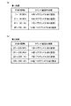
本実施例のパチンコ機1では、停止表示された大当り図柄の種類によって、1回の大当り遊技におけるラウンド遊技の回数が異なる。すなわち、図5(a)に示すように、第1特図が大当り図柄1〜50で停止表示された場合は(第1特図が大当り図柄で停止表示される場合は50%の確率で)、4回のラウンド遊技が行われる4ラウンド大当り遊技が行われ、第1特図が大当り図柄51〜90で停止表示された場合は(第1特図が大当り図柄で停止表示される場合は40%の確率で)、6回のラウンド遊技が行われる6ラウンド大当り遊技が行われ、第1特図が大当り図柄91〜94で停止表示された場合は(第1特図が大当り図柄で停止表示される場合は4%の確率で)、7回のラウンド遊技が行われる7ラウンド大当り遊技が行われ、第1特図が大当り図柄95〜100で停止表示された場合は(第1特図が大当り図柄で停止表示される場合は6%の確率で)、16回のラウンド遊技が行われる16ラウンド大当り遊技が行われる。また、図5(b)に示すように、第2特図が大当り図柄201〜250で停止表示された場合は(第2特図が大当り図柄で停止表示される場合は50%の確率で)4ラウンド大当り遊技が行われ、第2特図が大当り図柄251〜290で停止表示された場合は(第2特図が大当り図柄で停止表示される場合は40%の確率で)6ラウンド大当り遊技が行われ、第2特図が大当り図柄291〜294で停止表示された場合は(第2特図が大当り図柄で停止表示される場合は4%の確率で)7ラウンド大当り遊技が行われ、第2特図が大当り図柄295〜300で停止表示された場合は(第2特図が大当り図柄で停止表示される場合は6%の確率で)16ラウンド大当り遊技が行われる。
In the
本実施例のパチンコ機1において、1回のラウンド遊技は、9個の遊技球が入球した場合(9カウント)または30秒が経過した場合に終了するので、ほとんどの場合において1回のラウンド遊技では117個(9カウント×払出数13個)の遊技球が払い出される。従って、当然ながら、ラウンド遊技回数の多い大当り遊技の方が、ラウンド遊技回数が少ない大当り遊技よりも遊技者に多くの遊技球が払い出されることとなる。このため、ラウンド遊技回数のより多い大当り遊技が行われることを遊技者に期待させることができる。尚、このことは、遊技者にとっての有利度合が互いに異なる複数の大当り遊技(特定遊技)を実行可能であると捉えることができる。
In the
上述した大当り遊技の実行中は、セグメント表示部50のラウンド表示部55に実行中の大当り遊技の種類(ラウンド遊技回数)が表示される。すなわち、図4に示すように、ラウンド表示部55には3個のLEDが配置されており、このラウンド表示部55では、3個のLEDのうち左のLEDを点灯することで4ラウンド大当り遊技の実行中であることを示し、中のLEDを点灯することで6ラウンド大当り遊技の実行中であることを示し、右のLEDを点灯することで7ラウンド大当り遊技の実行中であることを示し、3個全てのLEDを点灯することで16ラウンド大当り遊技の実行中であることを示す。
During the execution of the above-mentioned jackpot game, the type (number of round games) of the jackpot game being executed is displayed on the
<特別図柄の保留>
遊技球が第1始動口24に入球すると、上述したように第1特図についての大当り判定や変動表示が行われるものの、これらの大当り判定や変動表示は、遊技球が第1始動口24に入球後に直ぐに行われるのではなく、取得された判定乱数を第1特図保留として一旦記憶する。そして、所定の条件が成立したら、記憶した第1特図保留に基づいて大当り判定や第1特図の変動表示を行う。このような第1特図保留は4個を上限として記憶される。第1特図保留の記憶数(第1特図保留数)は、セグメント表示部50の第1特図保留表示部53に表示される。すなわち、図4に示すように、第1特図保留表示部53には2個のLEDが配置されており、この第1特図保留表示部53では、2個のLEDのうち1個のLEDを点灯することで第1特図保留数が1個であることを示し、2個のLEDを点灯することで第1特図保留数が2個であることを示し、1個のLEDを点滅することで第1特図保留数が3個であることを示し、2個のLEDを点滅することで第1特図保留数が4個であることを示す。
<Holding special symbols>
When the game ball enters the
また、遊技球が第2始動口25に入球すると、上述したように第2特図についての大当り判定や変動表示が行われるものの、これらの大当り判定や変動表示も、遊技球が第2始動口25に入球後に直ぐに行われるのではなく、取得された判定乱数を第2特図保留として一旦記憶する。そして、所定の条件が成立したら、記憶した第2特図保留に基づいて大当り判定や第2特図の変動表示を行う。このような第2特図保留も4個を上限として記憶される。第2特図保留の記憶数(第2特図保留数)は、セグメント表示部50の第2特図保留表示部54に表示される。すなわち、図4に示すように、第2特図保留表示部54にも2個のLEDが配置されており、この第2特図保留表示部54では、2個のLEDのうち1個のLEDを点灯することで第2特図保留数が1個であることを示し、2個のLEDを点灯することで第2特図保留数が2個であることを示し、1個のLEDを点滅することで第2特図保留数が3個であることを示し、2個のLEDを点滅することで第2特図保留数が4個であることを示す。
Further, when the game ball enters the
尚、本実施例のパチンコ機1では、何れかの特別図柄の変動表示中や、何れかの特別図柄の確定表示中、大当り遊技中は、第1特図保留や第2特図保留が記憶されていても、これらの保留に係る大当り判定や変動表示は行わない。また、第1特図保留および第2特図保留のうち第1特図保留のみが記憶されている場合は、最先に記憶された第1特図保留に係る大当り判定および第1特図の変動表示を行うが、第2特図保留が記憶されている場合は第1特図保留が記憶されているか否かに拘わらず、最先に記憶された第2特図保留に係る大当り判定および第2特図の変動表示を行う。すなわち、第2特図を第1特図に優先して変動表示させる(いわゆる第2特図の優先変動機能を有する)。
In the
<普通図柄の変動表示、普図当り遊技>
図2を用いて前述したように、普通図柄作動ゲート27は右打ちされた遊技球が通過可能である。右打ちされた遊技球が普通図柄作動ゲート27を通過し、その遊技球がゲートセンサー27sにより検知されると、所定の判定乱数(後述する普図当り判定乱数)を取得し、該判定乱数に基づいて普図当りであるか外れであるかを判定する普図当り判定を行う。そして、この普図当り判定の結果に基づいて、普通図柄を変動表示させた後に停止表示させる。図4に示すように、セグメント表示部50には、普通図柄を表示する普図表示部56が設けられており、普図表示部56には2個のLEDが配置されている。普通図柄は、普図表示部56において、2個のLEDのうち点灯するLEDを切り換えることによって変動表示され、2個のLEDのうち所定のLEDを点灯した状態とすることで停止表示される。本実施例のパチンコ機1では、普通図柄として、2個のLEDのうち左のLEDを点灯させた普図当り図柄と、右のLEDを点灯させた普図外れ図柄の2種類の図柄を停止表示可能である。普図当り判定の結果が普図当りである場合は普通図柄が普図当り図柄で停止表示され、普図当り判定の結果が普図外れである場合は普通図柄が普図外れ図柄で停止表示される。こうして普通図柄を当り図柄または外れ図柄で停止表示したら、停止表示された図柄を確定させるべく、図柄が停止表示された状態を所定の時間が経過するまで維持する表示(確定表示)を行う。そして、普通図柄が普図当り図柄で停止表示された場合は、第2始動口25が開放状態となった後に閉鎖状態となる普図当り遊技が行われる。
<Variable display of normal symbols, games per ordinary symbols>
As described above with reference to FIG. 2, the normal
<普通図柄の保留>
遊技球が普通図柄作動ゲート27を通過すると、普図当り判定や普通図柄の変動表示が行われるものの、これらの普図当り判定や変動表示は、遊技球が普通図柄作動ゲート27を通過後に直ぐに行われるのではなく、取得された判定乱数を普図保留として一旦記憶する。そして、所定の条件が成立したら、記憶した普図保留に基づいて普図当り判定や普通図柄の変動表示を行う。このような普図保留も4個を上限として記憶される。普図保留の記憶数(普図保留数)は、セグメント表示部50の普図保留表示部57に表示される。すなわち、図4に示すように、普図保留表示部57には2個のLEDが配置されており、この普図保留表示部57では、2個のLEDのうち1個のLEDを点灯することで普図保留数が1個であることを示し、2個のLEDを点灯することで普図保留数が2個であることを示し、1個のLEDを点滅することで普図保留数が3個であることを示し、2個のLEDを点滅することで普図保留数が4個であることを示す。尚、本実施例のパチンコ機1では、普図保留が記憶されている場合において、普通図柄の変動表示中、普通図柄の確定表示中、普図当り遊技中の何れでもなければ、最先に記憶された普図保留に係る普図当り判定および普通図柄の変動表示を行う。
<Holding ordinary symbols>
When the game ball passes through the normal
<遊技状態>
ここで、本実施例のパチンコ機1では、大当り判定において大当りと判定される確率に係る遊技状態と、第2始動口25への遊技球の入球頻度に係る遊技状態とが適宜設定される。これらのうち大当り判定において大当りと判定される確率に係る遊技状態は、「大当り判定において大当りと判定される確率が低い(99.9分の1の確率である)低確率状態」または「大当り判定において大当りと判定される確率が高い(11.9分の1の確率である)高確率状態」に設定される。また、第2始動口25への遊技球の入球頻度に係る遊技状態は、「第2始動口25への遊技球の入球頻度が低い非電サポ状態」または「第2始動口25への遊技球の入球頻度が高い電サポ状態」に設定される。
<Game state>
Here, in the
上述した遊技状態の設定態様について図6を用いて説明する。尚、これらの遊技状態は大当り遊技終了後に設定されるため、図6では、図5を用いて前述したラウンド遊技の回数も再掲している。また、図6において、「高確回数」とは、高確率状態が設定された状態で実行可能な図柄変動遊技(特別図柄の変動表示)の回数であり、「電サポ回数」とは、電サポ状態が設定された状態で実行可能な図柄変動遊技(特別図柄の変動表示)の回数である。 The setting mode of the game state described above will be described with reference to FIG. Since these game states are set after the big hit game is completed, the number of round games described above is also shown again in FIG. 5 with reference to FIG. Further, in FIG. 6, the "high probability number" is the number of symbol variation games (variation display of special symbols) that can be executed in a state where a high probability state is set, and the "electric support number" is an electric support. This is the number of symbol variation games (special symbol variation display) that can be executed while the support state is set.
本実施例のパチンコ機1では、何れの大当り遊技が行われた場合であっても、大当り遊技終了後は高確率状態と電サポ状態が併せて設定されるものの、電サポ回数が大当り遊技の開始契機となった大当り図柄の種類によって異なる。すなわち、図6(a)(b)に示すように、高確回数については、何れの大当り図柄が停止表示された場合であっても6回に設定される。これに対して、電サポ回数については、図6(a)に示すように、第1特図が大当り図柄1〜45で停止表示された場合は(第1特図が大当り図柄で停止表示される場合は45%の確率で)25回に設定され、第1特図が大当り図柄46〜50、51〜90、91〜94で停止表示された場合は(第1特図が大当り図柄で停止表示される場合は5%+40%+4%=49%の確率で)50回に設定され、第1特図が大当り図柄95〜100で停止表示された場合は(第1特図が大当り図柄で停止表示される場合は6%の確率で)100回に設定される。また、図6(b)に示すように、第2特図が大当り図柄201〜245で停止表示された場合は(第2特図が大当り図柄で停止表示される場合は45%の確率で)25回に設定され、第2特図が大当り図柄246〜250、251〜290、291〜294で停止表示された場合は(第2特図が大当り図柄で停止表示される場合は5%+40%+4%=49%の確率で)50回に設定され、第2特図が大当り図柄295〜300で停止表示された場合は(第2特図が大当り図柄で停止表示される場合は6%の確率で)100回に設定される。
In the
尚、高確回数が6回に設定された後に図柄変動遊技(特別図柄の変動表示)が6回行われた場合は、高確率状態は終了し、電サポ状態が設定されたまま低確率状態が設定される。また、25回、50回、100回の電サポ回数が設定された後に該電サポ回数と同数の図柄変動遊技(特別図柄の変動表示)が行われた場合は、電サポ状態は終了し、非電サポ状態が設定される。遊技者にとっては、電サポ状態の方が非電サポ状態よりも有利な状態であることから、より多くの電サポ回数が設定されることを遊技者に期待させることができる。 If the symbol variation game (variation display of a special symbol) is performed 6 times after the high probability number is set to 6, the high probability state ends and the electric support state is set and the low probability state is set. Is set. In addition, if the same number of symbol variation games (special symbol variation display) as the number of times of electric support is performed after the number of times of electric support is set 25 times, 50 times, and 100 times, the electric support state ends. Non-electric support state is set. Since the electric support state is more advantageous than the non-electric support state for the player, it is possible to expect the player to set a larger number of electric support times.
ここで、セグメント表示部50には、上述した電サポ状態の設定中であることを示す電サポ表示部58が設けられている。すなわち、図4に示すように、電サポ表示部58には、3個のLEDが配置されており、電サポ状態の設定中は、この3個のLEDを点灯することによって電サポ状態の設定中であることを示す。また、図4に示すように、セグメント表示部50には、右打ちを行うことを示す右打ち表示部59が設けられている。電サポ状態の設定中は第2始動口25への遊技球の入球頻度が高く、且つ、第2始動口25は右打ちされた遊技球が入球可能であるので、電サポ状態の設定中は右打ちを行うことが遊技者にとって有益である。また、大入賞口28も右打ちされた遊技球が入球可能であるので、大当り遊技中も右打ちを行うことが遊技者にとって有益である。そこで、電サポ状態の設定中および大当り遊技中は、右打ち表示部59に配置された2個のLEDを点灯することによって右打ちを行うことを示す。
Here, the
<演出表示装置41の表示内容>
上述したような遊技の進行は、主に主制御基板200のCPU201によって行われる。本実施例のパチンコ機1では、上述したような遊技の進行に合わせて、演出表示装置41に種々の画像を表示する演出を行う。このような演出は、主にサブ制御基板220のCPU221によって行われる。
<Display contents of the
The progress of the game as described above is mainly performed by the
例えば、演出表示装置41では、第1特図または第2特図の変動表示(図柄変動遊技)に合わせた演出(以下「図柄変動演出」ともいう)が行われる。すなわち、特別図柄(第1特図または第2特図)の変動表示(図柄変動遊技)の開始タイミングと同期して、演出表示装置41において3つの識別図柄41a,41b,41cの変動表示を開始する。その後、特別図柄の変動時間が経過するまで種々の態様で識別図柄41a,41b,41cの変動表示を行う。そして、特別図柄の変動表示の終了タイミング(特別図柄の停止表示)と同期して識別図柄41a,41b,41cの変動表示を終了する。本実施例のパチンコ機1では、識別図柄として「1」〜「9」までの9つの数字を意匠化した図柄を表示可能である。
For example, in the
図7(a)には、3つの識別図柄41a,41b,41cが一斉に変動表示している様子が概念的に示されている。変動表示が開始されてから所定時間が経過すると、例えば、初めに左識別図柄41aが停止表示され、次に右識別図柄41cが停止表示され、最後に中識別図柄41bが停止表示される。これら演出表示装置41で停止表示される3つの識別図柄41a,41b,41cの組合せは、前述した第1特図表示部51または第2特図表示部52にて停止表示される特別図柄(第1特図または第2特図)と対応するように構成されている。例えば、第1特図または第2特図が大当り図柄で停止表示される場合は、演出表示装置41の3つの識別図柄41a,41b,41cが同じ図柄となる図柄組合せ(以下「ゾロ目」ともいう)で停止表示される。また、第1特図または第2特図が外れ図柄で停止表示される場合は、3つの識別図柄41a,41b,41cは同じ図柄で揃わない図柄組合せ(以下「バラケ目」ともいう)で停止表示される。尚、停止表示された識別図柄41a,41b,41cは、特別図柄の確定表示時間が経過するまで停止表示された状態となる(確定表示される)。
FIG. 7A conceptually shows how the three
このように、第1特図表示部51または第2特図表示部52で表示される特別図柄と、演出表示装置41で表示される3つの識別図柄41a,41b,41cとは、表示内容が互いに対応しており、変動表示中の特別図柄が停止表示する際には、3つの識別図柄41a,41b,41cも停止表示するようになっている。しかも、図2に示すように、演出表示装置41は、第1特図表示部51または第2特図表示部52(セグメント表示部50)よりも目に付き易い位置に設けられており、表示画面も大きく、表示内容も分かり易いので、遊技者は演出表示装置41の画面を見ながら遊技を行うことが通常である。従って、図7(b)に示すように、演出表示装置41の表示画面上で初めに停止表示される左識別図柄41aと、続いて停止表示される右識別図柄41cとが同じ図柄であった場合には、最後に停止表示される中識別図柄41bも同じ図柄で停止して、「大当り遊技が開始されるのではないか」と、遊技者は識別図柄の変動表示(図柄変動演出)を注視することになる。このように、2つの識別図柄(複数の識別図柄のうち一の識別図柄を除いた識別図柄)を同じ図柄(ゾロ目となり得る態様)で停止させて最後の識別図柄(一の識別図柄)を変動表示させた状態で行われる演出は「リーチ演出」と呼ばれており、このリーチ演出を発生させることで遊技興趣を高めることが可能である。
As described above, the display contents of the special symbol displayed on the first special
また、演出表示装置41の表示画面上の下部には、第1特図保留数を示すための第1保留表示領域41dと、第2特図保留数を示すための第2保留表示領域41eとが設定されている。本実施例のパチンコ機1では、第1保留表示領域41dに第1特図保留数と同数の「保留図柄(図中、小さい円形の図柄)」を表示することで第1特図保留数(上限数は4個)を示し、第2保留表示領域41eに第2特図保留数(上限数は4個)と同数の「保留図柄」を表示することで第2特図保留数を示す。従って、図7に示す例では、第1特図保留数が4個であり、第2特図保留数が4個であることが示されている。尚、当然ながら、演出表示装置41の表示画面上に表示された保留図柄によって示される保留数と、セグメント表示部50の第1特図保留表示部53および第2特図保留表示部54にて示される保留数とは一致する。
Further, in the lower part of the display screen of the
C.遊技制御処理 :
図8は、主制御基板200のCPU201が、遊技の進行に係る制御として行う遊技制御処理の大まかな流れを示したフローチャートである。遊技制御処理は、主制御基板200のCPU201によって、所定周期毎(例えば4m秒毎)に発生するタイマ割り込みに基づき行われる。以下、フローチャートに従って、主制御基板200のCPU201が行う遊技進行制御処理について説明する。尚、以下の説明では、CPU201の初期化処理や、割り込み禁止処理、割り込み許可処理などの周知の処理については、その説明を省略している。
C. Game control processing:
FIG. 8 is a flowchart showing a rough flow of a game control process performed by the
<出力処理>
図8に示すように、主制御基板200のCPU201は遊技制御処理を開始すると先ず、出力処理(S100)を行う。本実施例のパチンコ機1では、後述する各種処理において、サブ制御基板220を初めとする各種制御基板に向けて送信する各種コマンドをRAM203に確保された出力バッファに記憶する。出力処理(S100)では、このように出力バッファに記憶された各種コマンドを各種制御基板に向けて送信する。こうすることにより、例えば、サブ制御基板220では、遊技の進行に合わせた演出の制御が行われることになり、払出制御基板240では、払出モーター243を駆動して遊技球の払い出しが行われることとなる。
<Output processing>
As shown in FIG. 8, when the
<入力処理>
主制御基板200のCPU201は、続いて、入力処理(S200)を行う。本実施例のパチンコ機1では上述したように、第1始動口24、第2始動口25、一般入球口30の何れかに遊技球が入球した場合は3個の遊技球が払い出され、大入賞口28に遊技球が入球した場合は13個の遊技球が払い出される。そこで、入力処理(S200)の処理では、これらの入球を検知するセンサー類(第1始動口センサー24sや、第2始動口センサー25s、大入賞口センサー28s等)について、遊技球を検知したか否かを判断する。その結果、遊技球を検知している場合は、払い出す遊技球の数を示す払出コマンドを上述した出力バッファに記憶する。こうして出力バッファに記憶された払出コマンドは次回の出力処理(S100)で払出制御基板240に向けて送信される。
<Input processing>
The
<乱数更新処理>
主制御基板200のCPU201は、続いて、乱数更新処理(S300)を行う。本実施例のパチンコ機1では上述したように、大当り判定や普図当り判定は所定の判定乱数に基づいて行われる。詳しくは、大当り判定は「大当り判定乱数」に基づいて行われ、普図当り判定は「普図当り判定乱数」に基づいて行われる。また、本実施例のパチンコ機1における特別図柄の変動表示は後述する変動パターンに基づいて行われるが、この変動パターンは「変動パターン選択乱数」に基づいて選択される。また、本実施例のパチンコ機1では、大当り判定結果が大当りである場合は、100種類の大当り図柄(大当り図柄1〜100あるいは大当り図柄201〜300)のうち何れかの大当り図柄が停止表示されるが、この大当り図柄の種類は「図柄選択乱数」に基づいて選択される。乱数更新処理(S300)では、これらの乱数を更新する。尚、これらの乱数の更新は、乱数更新処理(S300)においてだけでなく、遊技制御処理を終了してから次の遊技制御処理を開始する(次のタイマ割り込み)までの期間にも行うこととしてもよい。また、乱数更新の専用回路を設けて、この専用回路で乱数を更新することとしてもよい。
<Random number update process>
The
<始動口等センサー検出処理>
主制御基板200のCPU201は、続いて、始動口等センサー検出処理(S400)を行う。この始動口等センサー検出処理(S400)では、普図保留、第1特図保留、第2特図保留を記憶する処理が行われる。すなわち、主制御基板200のCPU201は先ず、ゲートセンサー27sの検知結果に基づいて、遊技球が普通図柄作動ゲート27を通過したか否かを判断する。その結果、遊技球が普通図柄作動ゲート27を通過した場合は、普図保留数が上限値である4個に達しているか否かを判断する。そして、普図保留数が4個に達していなければ、普図当り判定乱数を取得すると共に該普図当り判定乱数を普図保留として記憶する。普図保留は、記憶した順序を識別できるように、RAM203に確保された普図保留記憶領域に記憶される。尚、遊技球が普通図柄作動ゲート27を通過していなかった場合や、普図保留数が既に4個に達していた場合は、新たな普図保留は記憶しない。
<Sensor detection process for starting port, etc.>
The
こうして普図保留の記憶に係る処理を行ったら、続いて、第1始動口センサー24sの検知結果に基づいて、遊技球が第1始動口24に入球したか否かを判断する。その結果、遊技球が第1始動口24に入球した場合は、第1特図保留数が上限値である4個に達しているか否かを判断する。そして、第1特図保留数が4個に達していなければ、大当り判定乱数、変動パターン選択乱数、図柄選択乱数を取得すると共にこれらの乱数を第1特図保留として記憶する。第1特図保留は、記憶した順序を識別できるように、RAM203に確保された第1特図保留記憶領域に記憶される。
After performing the process related to the storage of the normal drawing hold in this way, it is subsequently determined whether or not the game ball has entered the
ここで、第1特図の変動表示(図柄変動遊技)は、第1特図保留として取得された大当り判定乱数、変動パターン選択乱数、図柄選択乱数に基づいて行われる。また、第1特図の変動表示に合わせて行われる演出(図柄変動演出)も、第1特図保留として取得された大当り判定乱数、変動パターン選択乱数、図柄選択乱数に基づいて行われる。従って、第1特図保留を記憶した場合は、未だ該第1特図保留に基づく変動表示が開始されていなくても(変動開始条件が成立していなくても)、該第1特図保留に基づく変動表示や演出(第1特図保留に基づく図柄変動遊技や図柄変動演出)の態様を判定することが可能である。例えば、第1特図保留に基づく変動表示が行われる前であっても、該第1特図保留に基づく変動表示が行われた場合に大当り図柄が停止表示されるか否かや、リーチ演出が行われるか否か等を判定することが可能である。このような判定は事前判定と称されるものであって、本実施例のパチンコ機1では、第1特図保留を記憶すると、該第1特図保留について事前判定を行い、該事前判定結果を該第1特図保留と対応付けて記憶する。こうして、第1特図保留を記憶すると共に該第1特図保留についての事前判定結果を記憶したら、この事前判定結果を示す事前判定結果コマンドをRAM203の出力バッファに記憶する。こうして出力バッファに記憶された事前判定結果コマンドは次回の出力処理(S100)でサブ制御基板220に向けて送信される。こうすることによって、サブ制御基板220は、第1特図保留の事前判定結果に基づいて種々の演出を実行することが可能となる。尚、遊技球が第1始動口24に入球していなかった場合や、第1特図保留数が既に4個に達していた場合は、新たな第1特図保留は記憶せず、事前判定も行わない。
Here, the variation display (symbol variation game) of the first special figure is performed based on the jackpot determination random number, the variation pattern selection random number, and the symbol selection random number acquired as the first special figure hold. Further, the effect (symbol variation effect) performed according to the variation display of the first special figure is also performed based on the jackpot determination random number, the variation pattern selection random number, and the symbol selection random number acquired as the first special figure hold. Therefore, when the first special figure hold is stored, even if the fluctuation display based on the first special figure hold has not been started (even if the fluctuation start condition is not satisfied), the first special figure hold It is possible to determine the mode of the variation display and the effect (the symbol variation game and the symbol variation effect based on the first special figure hold) based on the above. For example, whether or not the jackpot symbol is stopped and displayed when the variation display based on the first special figure hold is performed even before the variation display based on the first special figure hold is performed, and the reach effect It is possible to determine whether or not Such a determination is called a preliminary determination, and in the
こうして第1特図保留の記憶に係る処理を行ったら、続いて、第2始動口センサー25sの検知結果に基づいて、遊技球が第2始動口25に入球したか否かを判断する。その結果、遊技球が第2始動口25に入球した場合は、第2特図保留数が上限値である4個に達しているか否かを判断する。そして、第2特図保留数が4個に達していなければ、大当り判定乱数、変動パターン選択乱数、図柄選択乱数を取得すると共にこれらの乱数を第2特図保留として記憶する。第2特図保留は、記憶した順序を識別できるように、RAM203に確保された第2特図保留記憶領域に記憶される。こうして第2特図保留を記憶したら、該第2特図保留についても上述と同様の事前判定を行い、該事前判定結果を該第2特図保留と対応付けて記憶する。こうして、第2特図保留を記憶すると共に該第2特図保留についての事前判定結果を記憶したら、この事前判定結果を示す事前判定結果コマンドをRAM203の出力バッファに記憶する。こうして出力バッファに記憶された事前判定結果コマンドも次回の出力処理(S100)でサブ制御基板220に向けて送信される。こうすることによって、サブ制御基板220は、第2特図保留の事前判定結果に基づいて種々の演出を実行することが可能となる。尚、遊技球が第2始動口25に入球していなかった場合や、第2特図保留数が既に4個に達していた場合は、新たな第2特図保留は記憶せず、事前判定も行わない。
After performing the process related to the storage of the first special figure hold in this way, it is subsequently determined whether or not the game ball has entered the
<普通動作処理>
主制御基板200のCPU201は、続いて、普通動作処理(S500)を行う。この普通動作処理(S500)では、普通図柄を変動表示させたり、普図当り遊技を実行したりする処理が行われる。すなわち、主制御基板200のCPU201は先ず、普図当り遊技中、普通図柄の変動表示中、普通図柄の確定表示中の何れかであるか否かを判断する。その結果、普図当り遊技中、普通図柄の変動表示中、普通図柄の確定表示中の何れでもない場合は、上述の普図保留記憶領域に普図保留が記憶されているか否かを判断する。その結果、普図保留記憶領域に普図保留が記憶されている場合は、記憶されている普図保留のうち最先に記憶された普図保留を読み出す。そして、読み出した普図保留、すなわち、普図当り判定乱数に基づいて普図当り判定を行う。
<Normal operation processing>
The
普図当り判定を行ったら、該普図当り判定の結果が普図当りであるか否かを判断する。その結果、普図当り判定の結果が普図当りである場合は、今回の普通図柄の変動表示にて停止表示する図柄(停止図柄)として普図当り図柄を記憶する。すなわち、今回の普通図柄の変動表示の結果として普図表示部56の左のLED(図4参照)を点灯させることを記憶する。これに対して、普図当り判定の結果が普図外れである場合は、今回の普通図柄の変動表示にて停止表示する図柄(停止図柄)として普図外れ図柄を記憶する。すなわち、今回の普通図柄の変動表示の結果として普図表示部56の右のLED(図4参照)を点灯させることを記憶する。
After the normal figure hit determination is performed, it is determined whether or not the result of the normal figure hit determination is a normal figure hit. As a result, when the result of the normal symbol hit determination is the normal symbol hit, the normal symbol hit symbol is stored as the symbol (stop symbol) to be stopped and displayed in the variation display of the normal symbol this time. That is, it is stored that the LED (see FIG. 4) on the left side of the normal
こうして、今回の普通図柄の変動表示の結果として普図表示部56の左のLEDを点灯させること、あるいは、普図表示部56の右のLEDを点灯させることを記憶したら、普通図柄の変動時間を設定して、普通図柄の変動表示を開始する。そして、今回の普図当り判定の対象となった普図保留を普図保留記憶領域から消去する。
In this way, if it is memorized that the LED on the left of the normal
以上は、普図当り遊技中、普通図柄の変動表示中、普通図柄の確定表示中の何れでもない場合の処理について説明した。これに対して、普通図柄の変動表示中である場合は、変動表示中の普通図柄の変動時間が経過したか否かを判断する。その結果、変動時間が経過したと判断された場合は、変動表示中の普通図柄を予め記憶しておいた態様で停止表示する。すなわち、普図当り判定の結果が普図当りであった場合は普図表示部56の左のLEDを点灯した状態とし(普図当り図柄を停止表示し)、普図当り判定の結果が外れであった場合は普図表示部56の右のLEDを点灯した状態した状態とする(外れ図柄を停止表示する)。このように普通図柄が停止表示されたら、普通図柄の確定表示が開始されるので、普通図柄の確定表示時間を設定する。
The above has described the processing when the game is not per game, the normal symbol is being displayed in a variable manner, or the normal symbol is being displayed in a fixed manner. On the other hand, when the fluctuation display of the normal symbol is in progress, it is determined whether or not the fluctuation time of the normal symbol in the fluctuation display has elapsed. As a result, when it is determined that the fluctuation time has elapsed, the normal symbol being displayed in the fluctuation display is stopped and displayed in a stored manner in advance. That is, if the result of the normal figure hit determination is the normal figure hit, the LED on the left of the normal
以上は、普通図柄の変動表示中である場合の処理について説明した。これに対して、普通図柄の確定表示中である場合は、確定表示時間が経過したか否かを判断する。その結果、確定表示時間が経過した場合は、今回停止表示(確定表示)された普通図柄が普図当り図柄(普図表示部56の左のLEDの点灯)であるか否かを判断する。その結果、停止表示された普通図柄が普図当り図柄であった場合は、普図当り遊技における第2始動口25の開放パターン(開放回数、開放時間、閉鎖時間など)を設定した後、普図当り遊技を開始する。
The above has described the processing when the variable display of the normal symbol is in progress. On the other hand, when the confirmation display of the normal symbol is in progress, it is determined whether or not the confirmation display time has elapsed. As a result, when the confirmed display time has elapsed, it is determined whether or not the normal symbol that has been stopped and displayed (confirmed display) this time is a symbol per normal symbol (the LED on the left of the regular
以上は、普通図柄の確定表示中である場合の処理について説明した。これに対して、普図当り遊技中である場合は、上述の開放パターンで第2始動口25が開放状態・閉鎖状態となるように、始動口ソレノイド26mを制御して開閉扉26を動作させる。そして、この開放パターンに従う制御が終了したら普図当り遊技を終了する。
The above has described the processing when the confirmation display of the normal symbol is in progress. On the other hand, when the game is being played per normal drawing, the opening / closing
ここで、図6を用いて前述したように、本実施例のパチンコ機1では、第2始動口25への遊技球の入球頻度に係る遊技状態が「第2始動口25への遊技球の入球頻度が低い非電サポ状態」または「第2始動口25への遊技球の入球頻度が高い電サポ状態」に設定される。このような非電サポ状態および電サポ状態の設定は次のように実現される。
Here, as described above with reference to FIG. 6, in the
すなわち、電サポ状態は非電サポ状態と比較して、普図当り判定の結果が普図当りとなる確率(普図当り確率)が高く、普通図柄の変動時間(普図変動時間)が短く、普図当り遊技における第2始動口25の開放時間が長く設定される。従って、電サポ状態は非電サポ状態と比較して、第2始動口25が高頻度で開放状態になるとともに該開放状態にある期間が長くなるので、第2始動口25への遊技球の入球頻度が高くなる(高頻度状態)。例えば、非電サポ状態が設定されている場合は、普図当り確率を100分の1の確率に設定し(普図保留として取得可能な普図当り判定乱数のうち100分の1の乱数を普図当りとし)、普図変動時間を20秒に設定し、普図当り遊技における第2始動口25の開放時間を0.3秒(0.1秒×3回開放)に設定する。これに対して、電サポ状態が設定されている場合は、普図当り確率を100分の99の確率に設定し(普図保留として取得可能な普図当り判定乱数のうち100分の99の乱数を普図当りとし)、普図変動時間を1秒に設定し、普図当り遊技における第2始動口25の開放時間を4.5秒(1.5秒×3回開放)に設定する。
That is, in the electric support state, the probability that the result of the normal figure hit judgment will be the normal figure hit (probability of hitting the normal figure) is higher than that in the non-electric support state, and the fluctuation time of the normal symbol (normal figure fluctuation time) is shorter. , The opening time of the
<特別動作処理>
主制御基板200のCPU201は、続いて、特別動作処理(S600)を行う。この特別動作処理(S600)では、特別図柄(第1特図または第2特図)を変動表示させたり、大当り遊技を実行したりする処理が行われる。すなわち、主制御基板200のCPU201は先ず、大当り遊技中、特別図柄(第1特図または第2特図)の変動表示中、特別図柄(第1特図または第2特図)の確定表示中の何れかであるか否かを判断する。その結果、大当り遊技中、特別図柄の変動表示中、特別図柄の確定表示中の何れでもない場合は、第2特図保留記憶領域に第2特図保留が記憶されているか否かを判断する。その結果、第2特図保留記憶領域に第2特図保留が記憶されている場合は、記憶されている第2特図保留のうち最先に記憶された第2特図保留(大当り判定乱数、変動パターン選択乱数、図柄選択乱数)を読み出す。そして、読み出した第2特図保留に含まれる大当り判定乱数に基づいて大当り判定を行う。
<Special operation processing>
The
これに対して、第2特図保留記憶領域に第2特図保留が記憶されていない場合は、今度は、第1特図保留記憶領域に第1特図保留が記憶されているか否かを判断する。その結果、第1特図保留記憶領域に第1特図保留が記憶されている場合は、記憶されている第1特図保留のうち最先に記憶された第1特図保留(大当り判定乱数、図柄選択乱数、変動パターン選択乱数)を読み出す。そして、読み出した第1特図保留に含まれる大当り判定乱数に基づいて大当り判定を行う。 On the other hand, if the second special figure hold is not stored in the second special figure hold storage area, this time, it is determined whether or not the first special figure hold is stored in the first special figure hold storage area. to decide. As a result, when the first special figure hold is stored in the first special figure hold storage area, the first special figure hold (big hit determination random number) stored first among the stored first special figure hold is stored. , Symbol selection random number, fluctuation pattern selection random number) is read. Then, the jackpot determination is performed based on the jackpot determination random number included in the read first special figure hold.
ここで、図6を用いて前述したように、本実施例のパチンコ機1では、大当り判定において大当りと判定される確率に係る遊技状態は「大当り判定において大当りと判定される確率が低い(99.9分の1の確率である)低確率状態」または「大当り判定において大当りと判定される確率が高い(11.9分の1の確率である)高確率状態」に設定される。このような低確率状態あるいは高確率状態の設定は次のように実現される。すなわち、低確率状態が設定されている場合は、第1特図保留または第2特図保留として取得可能な大当り判定乱数のうち99.9分の1の乱数を大当りとし、高確率状態が設定されている場合は、第1特図保留または第2特図保留として取得可能な大当り判定乱数のうち11.9分の1の乱数を大当りとする。
Here, as described above with reference to FIG. 6, in the
こうして第1特図保留または第2特図保留について大当り判定を行ったら、該大当り判定の結果が大当りであるか否かを判断する。その結果、大当り判定の結果が大当りである場合は、今回読み出した第1特図保留または第2特図保留に含まれる図柄選択乱数に基づいて、今回の特別図柄の変動表示(図柄変動遊技)にて停止表示する大当り図柄の種類を選択する。すなわち、図5を用いて前述したように、本実施例のパチンコ機1では、第1特図としては大当り図柄1〜100が停止表示可能であり、第2特図としては大当り図柄201〜300が停止表示可能である。そこで、第1特図保留を読み出した場合は、大当り図柄1〜100に図柄選択乱数が割り振られた図柄選択テーブル(図示省略)を参照して、第1特図保留として読み出した図柄選択乱数に対応する大当り図柄を、停止表示する図柄として選択する。また、第2特図保留を読み出した場合は、大当り図柄201〜300に図柄選択乱数が割り振られた図柄選択テーブルを参照して、第2特図保留として読み出した図柄選択乱数に対応する大当り図柄を、停止表示する図柄として選択する。尚、図柄選択テーブルは、主制御基板200のROM202に予め記憶されている。
When the jackpot determination is made for the first special figure hold or the second special figure hold in this way, it is determined whether or not the result of the jackpot determination is a jackpot. As a result, if the result of the jackpot determination is a jackpot, the variation display of the special symbol this time (symbol variation game) is based on the symbol selection random number included in the first special symbol hold or the second special symbol hold read this time. Select the type of jackpot symbol to be stopped and displayed with. That is, as described above with reference to FIG. 5, in the
一方、大当り判定の結果が外れである場合においては、第1特図保留を読み出した場合は外れ図柄101を停止表示する図柄として選択し、第2特図保留を読み出した場合は外れ図柄301を停止表示する図柄として選択する。尚、停止表示する図柄として選択された大当り図柄、外れ図柄は、RAM203に確保された停止図柄記憶領域に記憶される。
On the other hand, when the result of the jackpot determination is out of order, when the first special figure hold is read, the off symbol 101 is selected as the symbol to be stopped and displayed, and when the second special figure hold is read, the off symbol 301 is selected. Select as the symbol to be stopped and displayed. The jackpot symbol and the missed symbol selected as the symbol to be stopped and displayed are stored in the stop symbol storage area secured in the
こうして停止表示する図柄を選択したら、特別図柄の変動表示(図柄変動遊技)の変動パターンを選択する。変動パターンとは、特別図柄(第1特図または第2特図)が変動表示を開始してから停止表示するまでの時間(変動時間)であり、各変動パターンには他の変動パターンと識別するための情報(変動パターンID)が付されている。変動パターンを選択する処理では変動パターン選択テーブルを参照する。変動パターン選択テーブルとは、図9に示すように、複数の変動パターン(変動パターンID、変動時間)に変動パターン選択乱数が割り振られたテーブルである。変動パターンを選択する処理では、このような変動パターン選択テーブルにおいて、今回第1特図保留または第2特図保留として読み出した変動パターン選択乱数に対応する変動パターンを、今回の変動パターンとして決定する。従って、各変動パターンが選択される確率は、取得可能な変動パターン選択乱数のうち各変動パターンに割り振られた乱数の割合によって決定される。 After selecting the symbol to be stopped and displayed in this way, the variation pattern of the variation display (symbol variation game) of the special symbol is selected. The fluctuation pattern is the time (variation time) from the start of the fluctuation display to the stop display of the special symbol (first special figure or the second special figure), and each fluctuation pattern is distinguished from other fluctuation patterns. Information (variation pattern ID) is attached. In the process of selecting the fluctuation pattern, the fluctuation pattern selection table is referred to. As shown in FIG. 9, the variation pattern selection table is a table in which variation pattern selection random numbers are assigned to a plurality of variation patterns (variation pattern ID, variation time). In the process of selecting the variation pattern, in such a variation pattern selection table, the variation pattern corresponding to the variation pattern selection random number read out as the first special figure hold or the second special figure hold this time is determined as the current variation pattern. .. Therefore, the probability that each variation pattern is selected is determined by the ratio of the random numbers assigned to each variation pattern among the obtainable variation pattern selection random numbers.
このように選択された変動パターンは後述の変動パターン指定コマンドとして、サブ制御基板220に向けて送信される。サブ制御基板220のCPU221は、変動パターン指定コマンドを受信すると、該変動パターン指定コマンドに基づいて今回の図柄変動遊技の変動パターンを認識し、該変動パターンに基づく演出パターンで図柄変動演出を実行する。
The variation pattern selected in this way is transmitted to the
上述した変動パターンを選択する処理では、常時同じ変動パターン選択テーブルを参照するのではなく、図10に示すように、特別図柄の種類(第1特図または第2特図)や、現在設定されている遊技状態、大当り判定の結果、記憶されている第1特図保留および第2特図保留の数などの種々の遊技進行状況に対応する変動パターン選択テーブルを参照する。こうすることで、種々の遊技進行状況に対応する変動パターンを選択可能となり、ひいては、サブ制御基板220のCPU221は種々の遊技進行状況に対応する演出パターンで図柄変動演出を実行可能となる。例えば、サブ制御基板220のCPU221は、大当り判定の結果が大当りである場合は、リーチ演出の後に識別図柄41a,41b,41cをゾロ目で停止表示する図柄変動演出を実行し、大当り判定の結果が外れである場合は、識別図柄41a,41b,41cをバラケ目で停止表示する図柄変動演出を実行する。また、大当り判定の結果が外れである場合において所定の変動パターンが選択された場合はリーチ演出を行う。尚、各変動パターン選択テーブルは、主制御基板200のROM202に予め記憶されている。
In the process of selecting the fluctuation pattern described above, the type of special symbol (first special figure or second special figure) and the current setting are set as shown in FIG. 10 instead of always referring to the same fluctuation pattern selection table. Refer to the variation pattern selection table corresponding to various game progress states such as the game state, the result of the jackpot determination, and the number of stored first special figure hold and second special figure hold. By doing so, it becomes possible to select a variation pattern corresponding to various game progress states, and by extension, the
こうして、今回の特別図柄の変動表示にて停止表示させる図柄を選択すると共に、今回の特別図柄の変動表示の変動パターンを選択したら、特別図柄の変動表示を開始する。そして、今回選択された変動パターンを示す変動パターン指定コマンドをRAM203の出力バッファに記憶する。このように出力バッファに記憶された変動パターン指定コマンドは、次回の出力処理(S100)でサブ制御基板220に向けて送信される。また、今回の大当り判定の対象となった第1特図保留または第2特図保留を、第1特図保留記憶領域または第2特図保留記憶領域から消去する。
In this way, when the symbol to be stopped and displayed in the variation display of the special symbol this time is selected and the variation pattern of the variation display of the special symbol this time is selected, the variation display of the special symbol is started. Then, the variation pattern specification command indicating the variation pattern selected this time is stored in the output buffer of the
以上は、大当り遊技中、特別図柄(第1特図または第2特図)の変動表示中、特別図柄の確定表示中の何れでもない場合の処理について説明した。これに対して、特別図柄の変動表示中である場合は、変動表示中の特別図柄の変動時間が経過したか否かを判断する。その結果、変動時間が経過したと判断された場合は、変動表示中の特別図柄を予め停止図柄記憶領域に記憶しておいた図柄で停止表示する(確定表示を開始する)。このように特別図柄が停止表示されたら、特別図柄の確定表示が開始されるので、特別図柄の確定表示時間を設定する。そして、特別図柄を停止表示したことを示す変動停止コマンドをRAM203の出力バッファに記憶する。このように出力バッファに記憶された変動停止コマンドは、次回の出力処理(S100)でサブ制御基板220に向けて送信される。
The above has described the processing when neither of the big hit game, the variable display of the special symbol (first special symbol or the second special symbol), or the final display of the special symbol is displayed. On the other hand, when the variation display of the special symbol is in progress, it is determined whether or not the variation time of the special symbol in the variation display has elapsed. As a result, when it is determined that the fluctuation time has elapsed, the special symbol being displayed in the fluctuation is stopped and displayed at the symbol stored in the stop symbol storage area in advance (the confirmation display is started). When the special symbol is stopped and displayed in this way, the final display of the special symbol is started, so the final display time of the special symbol is set. Then, a variable stop command indicating that the special symbol has been stopped and displayed is stored in the output buffer of the
特別図柄の確定表示中である場合は、確定表示時間が経過したか否かを判断する。その結果、確定表示時間が経過した場合は、今回停止表示(確定表示)された特別図柄が大当り図柄であるか否かを判断する。その結果、停止表示された特別図柄が外れ図柄であった場合は、高確率状態が設定されているか否かを判断し、高確率状態が設定されている場合は、高確回数を1回減算する。その結果、高確回数が0回になったら、高確率状態に代えて低確率状態を設定する。また、電サポ状態が設定されているか否かも判断し、電サポ状態が設定されている場合は電サポ回数を1回減算する。その結果、電サポ回数が0回になったら、電サポ状態に代えて非電サポ状態を設定する。このように遊技状態を設定した場合は、設定された遊技状態を示す遊技状態指定コマンドをRAM203の出力バッファに記憶する。このように出力バッファに記憶された遊技状態指定コマンドは、次回の出力処理(S100)でサブ制御基板220に向けて送信される。
When the confirmation display of the special symbol is in progress, it is determined whether or not the confirmation display time has elapsed. As a result, when the confirmed display time has elapsed, it is determined whether or not the special symbol displayed (confirmed display) this time is a jackpot symbol. As a result, if the special symbol that is stopped and displayed is an out-of-order symbol, it is determined whether or not the high probability state is set, and if the high probability state is set, the high probability number is subtracted once. do. As a result, when the high probability number becomes 0, the low probability state is set instead of the high probability state. It is also determined whether or not the electric support state is set, and if the electric support state is set, the number of electric support is subtracted once. As a result, when the number of times of electric support becomes 0, the non-electric support state is set instead of the electric support state. When the game state is set in this way, the game state specification command indicating the set game state is stored in the output buffer of the
これに対して、停止表示された特別図柄が大当り図柄であった場合は、大当り遊技における大入賞口28の開放パターン(開放回数、開放時間、閉鎖時間など)を設定する。図5を用いて前述したように、本実施例のパチンコ機1では、停止表示された大当り図柄の種類によって大当り遊技中のラウンド遊技の回数が異なる。従って、停止表示された大当り図柄の種類に対応して大入賞口28の開放パターンを設定する。こうして大入賞口28の開放パターンを設定したら、大当り遊技を開始する。そして、大当り遊技の開始を示す大当り遊技開始コマンドをRAM203の出力バッファに記憶する。この大当り遊技開始コマンドには、今回開始する大当り遊技におけるラウンド遊技回数を示す情報も含まれている。出力バッファに記憶された大当り遊技開始コマンドは、次回の出力処理(S100)でサブ制御基板220に向けて送信される。
On the other hand, when the special symbol displayed as stopped is a jackpot symbol, the opening pattern (opening number, opening time, closing time, etc.) of the
一方、大当り遊技中である場合は、上述の開放パターンで大入賞口28が開放状態・閉鎖状態となるように、大入賞口ソレノイド29mを制御して開閉扉29を動作させる。そして、ラウンド遊技の開始時には、ラウンド遊技の開始を示すラウンド遊技開始コマンドをRAM203の出力バッファに記憶し、ラウンド遊技の終了時には、ラウンド遊技の終了を示すラウンド遊技終了コマンドをRAM203の出力バッファに記憶される。このように出力バッファに記憶されたラウンド遊技開始コマンド、ラウンド遊技終了コマンドは、次回の出力処理(S100)でサブ制御基板220に向けて送信される。
On the other hand, when the big hit game is in progress, the opening / closing
また、上述の開放パターンに従う大入賞口ソレノイド29mの制御(開閉扉29の動作)が終了したら大当り遊技を終了する。そして、大当り遊技の終了を示す大当り遊技終了コマンドをRAM203の出力バッファに記憶される。このように出力バッファに記憶された大当り遊技終了コマンドは、次回の出力処理(S100)でサブ制御基板220に向けて送信される。大当り遊技を終了したら、図6を用いて前述したように、遊技状態を高確率状態且つ電サポ状態に設定する。このとき、高確回数は、何れの大当り図柄が停止表示された場合も6回に設定されるが、電サポ回数は、停止表示された大当り図柄の種類に応じて、25回、50回、100回の何れかに設定される。このように遊技状態を設定した場合は、設定された遊技状態(高確回数や電サポ回数も含む)を示す遊技状態指定コマンドをRAM203の出力バッファに記憶する。このように出力バッファに記憶された遊技状態指定コマンドは、次回の出力処理(S100)でサブ制御基板220に向けて送信される。
Further, when the control (operation of the opening / closing door 29) of the large winning
尚、特別図柄は「識別情報」として捉えることもでき、特別図柄を変動表示させる主制御基板200のCPU201は「識別情報表示手段」として捉えることもでき、大当り図柄は「特定態様」として捉えることもできる。また、大入賞口28は「可変入球口」として捉えることもでき、大当り遊技は「特定遊技」として捉えることもでき、大当り遊技を実行する主制御基板200のCPU201は「特定遊技実行手段」として捉えることもできる。
The special symbol can be regarded as "identification information", the
<保留数処理>
主制御基板200のCPU201は、続いて、保留数処理(S700)を行う。この保留数処理(S700)では、第1特図保留記憶領域に記憶されている第1特図保留の数、および、第2特図保留記憶領域に記憶されている第2特図保留の数を読み出して、これらの数を示す保留数伝達コマンドをRAM203の出力バッファに記憶する。こうして出力バッファに記憶された保留数伝達コマンドも次回の出力処理(S100)でサブ制御基板220に向けて送信される。こうすることによって、サブ制御基板220は、第1特図保留の数や第2特図保留の数に対応する保留図柄を演出表示装置41に表示する等、これらの数に基づいて種々の演出を実行することが可能となる。
<Holding number processing>
The
D.演出制御処理 :
図11は、サブ制御基板220のCPU221が、演出に係る制御として行う演出制御処理の大まかな流れを示したフローチャートである。演出制御処理は、サブ制御基板220のCPU221によって、所定周期毎(例えば10m秒毎)に発生するタイマ割り込みに基づき行われる。以下、フローチャートに従って、サブ制御基板220のCPU221が行う演出制御処理について説明する。尚、以下の説明では、CPU221の初期化処理や、割り込み禁止処理、割り込み許可処理などの周知の処理については、その説明を省略している。
D. Production control processing:
FIG. 11 is a flowchart showing a rough flow of the effect control process performed by the
演出制御処理を開始すると、サブ制御基板220のCPU221は先ず、コマンド解析処理を行う(S800)。ここで、サブ制御基板220のCPU221は、主制御基板200からコマンドを受信するたびに、外部割り込み処理として、このコマンドをRAM223の受信コマンド記憶領域に記憶している。コマンド解析処理(S800)では、この受信コマンド記憶領域に記憶されたコマンド、すなわち、主制御基板200から受信したコマンドに対応する演出を決定し、この演出を行うために画像音声制御基板230やランプ制御基板226等に送信するコマンドをRAM223に確保された出力バッファに記憶する。
When the effect control process is started, the
サブ制御基板220のCPU221は、続いて、出力処理を行う(S900)。この処理では、RAM223の出力バッファに記憶されたコマンドを画像音声制御基板230やランプ制御基板226等に送信する。サブ制御基板220からコマンドを受信すると、画像音声制御基板230は、受信したコマンドに対応する画像を演出表示装置41に表示すると共に、受信したコマンドに対応する音声を各種スピーカー6a,6b等から出力する。また、ランプ制御基板226は、受信したコマンドに対応する発光パターンで各種ランプ5a〜5c等を発光させる。
The
以上のように、サブ制御基板220は、画像音声制御基板230やランプ制御基板226等と協働して各種演出を実行するが、本明細書では説明の便宜上、サブ制御基板220が画像音声制御基板230やランプ制御基板226等と協働して各種演出を実行することを、単に、「サブ制御基板220のCPU221が各種演出を実行する」とも表現する。
As described above, the
図12には、主制御基板200から受信したコマンドに対応して、サブ制御基板220のCPU221が行う処理を示している。図12に示すように、サブ制御基板220のCPU221は、事前判定結果コマンドを受信した場合は、事前判定結果に基づく演出である事前演出を行う。例えば、事前判定結果に対応するキャラクター等の画像を演出表示装置41に表示させたり、演出表示装置41の第1保留表示領域41dや第2保留表示領域41fに表示する保留図柄の態様を事前判定結果に対応する態様としたりする。尚、事前判定演出は、事前判定結果コマンドを受信した場合において、常時行う必要はなく、所定の条件が成立したら(例えば所定の実行抽選に当選したら)行うこととしてもよい。
FIG. 12 shows the processing performed by the
また、図12に示すように、サブ制御基板220のCPU221は、保留数伝達コマンドを受信すると、このコマンドによって示される第1特図保留数および第2特図保留数と同数の保留図柄を、演出表示装置41の第1保留表示領域41dや第2保留表示領域41fに表示する。尚、第1特図保留数および第2特図保留数の両方を常時表示する必要はなく、例えば、左打ちが行われる非電サポ状態、すなわち、第1特図主体の遊技が行われる状態においては、第1特図保留数を表示し、右打ちが行われる非電サポ状態、すなわち、第2特図主体の遊技が行われる状態においては、第2特図保留数を表示することとしてもよい。
Further, as shown in FIG. 12, when the
また、図12に示すように、サブ制御基板220のCPU221は、変動パターン指定コマンドを受信すると、特別図柄(第1特図または第2特図)の変動表示に合わせて、変動パターン指定コマンドが示す変動パターンに対応する図柄変動演出(識別図柄41a,41b,41cの変動表示を含む)を開始する。図柄変動演出は、変動パターンに対応して行われるので、図柄変動演出の一環として行われるリーチ演出(図7(b)参照)も、対応する変動パターンが選択された場合に行われる。詳しくは、大当り判定の結果が大当りである場合にリーチ演出に対応する変動パターンが選択されると、リーチ演出が行われた後、識別図柄41a,41b,41cがゾロ目で停止表示する図柄変動演出が行われる。また、大当り判定の結果が外れである場合にリーチ演出に対応する変動パターンが選択されると、リーチ演出が行われた後、識別図柄41a,41b,41cがバラケ目で停止表示する図柄変動演出が行われる。そして、図柄変動演出の実行中に変動停止コマンドを受信すると、サブ制御基板220のCPU221は、識別図柄41a,41b,41cをゾロ目またはバラケ目で停止表示する。
Further, as shown in FIG. 12, when the
また、図12に示すように、サブ制御基板220のCPU221は、大当り遊技開始コマンドを受信すると、大当り遊技中であることを示す大当り遊技演出を開始する。例えば、大当り遊技が開始されるタイミングで、大当り遊技の開始を示すファンファーレ演出を実行すると共に、大当り遊技中であることを示す動画(いわゆるムービー)の表示を開始する。また、開始された大当り遊技のラウンド遊技回数(4ラウンド大当り遊技、6ラウンド大当り遊技、7ラウンド大当り遊技、16ラウンド大当り遊技の何れか)を示唆する演出や、開始された大当り遊技終了後に設定される遊技状態や、高確回数(6回)、電サポ回数(25回、50回、100回の何れか)を示唆する演出を実行する。
Further, as shown in FIG. 12, when the
また、図12に示すように、サブ制御基板220のCPU221は、大当り遊技中にラウンド遊技開始コマンドを受信すると、ラウンド遊技中であることを示すラウンド遊技演出を(例えば、大当り遊技演出に重ねて)開始する。例えば、実行中の大当り遊技におけるラウンド遊技の回数を示す演出(例えば、1R,2R,3R・・・を表示する演出など)を開始する。そして、ラウンド遊技終了コマンドを受信すると、ラウンド遊技演出を終了し、大当り遊技終了コマンドを受信すると、大当り遊技演出を終了する。
Further, as shown in FIG. 12, when the
また、図12に示すように、サブ制御基板220のCPU221は、遊技状態指定コマンドを受信すると、設定された遊技状態に対応する演出を開始する。例えば、識別図柄41a,41b,41cやその背景画像を遊技状態に対応する態様(色彩や形状など)とする演出を実行したり、高確率状態が設定された場合は残りの高確回数を表示する演出を開始したり、電サポ状態が設定された場合は残りの電サポ回数を表示する演出を開始したりする。
Further, as shown in FIG. 12, when the
E.役物上昇演出 :
ここで、本実施例のパチンコ機1では、上述した図柄変動演出の一環として、「移動役物70」を下から上へ移動させる「役物上昇演出」を実行可能である。以下では、このような「役物上昇演出」について説明する。
E. Character rising production:
Here, in the
E−1.役物上昇演出の概要 :
図13は、本実施例の「役物上昇演出」が行われる様子を示す説明図である。図13に示すように、「役物上昇演出」では、演出表示装置41の前方において「移動役物70」を下から上に移動させる演出を行う。演出用開口部40が設けられた遊技盤20と演出表示装置41との間には、「移動役物70」を収容するスペースが確保されており、「役物上昇演出」が行われていない場合は、「移動役物70」は該スペース(原点位置)に収容されている。これに対して、「役物上昇演出」が行われる場合は、「移動役物70」は該スペース(原点位置)から上方の位置(出現位置)へ移動されて、演出表示装置41の前方に出現する。このような「役物上昇演出」が行われる場合は、遊技者は演出用開口部40を通して、演出表示装置41の前方に出現した「移動役物70」のLUCKの文字を視認することができる。
E-1. Outline of the character rising production:
FIG. 13 is an explanatory diagram showing how the “character rising effect” of this embodiment is performed. As shown in FIG. 13, in the “accessory rising effect”, an effect of moving the “moving
本実施例のパチンコ機1では、「役物上昇演出」が実行されるか否かによって「リーチ期待度」や「大当り期待度」が異なる。「リーチ期待度」とはリーチ演出が行われる可能性であり、「大当り期待度」とは大当り判定で「大当り」と判定された可能性(大当り遊技が行われる可能性)である。このような「リーチ期待度」や「大当り期待度」は、「役物上昇演出」が行われない場合よりも、「役物上昇演出」が行われる場合の方が高い。
In the
このような「役物上昇演出」に係る「リーチ期待度」および「大当り期待度」は、「役物上昇演出」の実行確率、すなわち、「役物上昇演出」に対応する変動パターンが選択される確率を適宜設定することによって実現される。つまり、「役物上昇演出」は、「役物上昇演出」に対応する変動パターンが選択された場合に実行されるように構成して、このような変動パターンが選択される確率を適宜設定することによって、上述したような「リーチ期待度」および「大当り期待度」を実現することができる。 For the "reach expectation" and "big hit expectation" related to such "character rising effect", the execution probability of the "character rising effect", that is, the fluctuation pattern corresponding to the "character rising effect" is selected. It is realized by setting the probability of That is, the "character rising effect" is configured to be executed when the variation pattern corresponding to the "character rising effect" is selected, and the probability that such a variation pattern is selected is appropriately set. Thereby, the above-mentioned "reach expectation" and "big hit expectation" can be realized.
例えば、図14に示すように、大当り判定の結果が大当りである場合(あるいはリーチ演出を行う場合)は、「役物上昇演出を行わない変動パターンが選択される確率(役物上昇演出を行わない確率)」よりも、「役物上昇演出を行う変動パターンが選択される確率(役物上昇演出を行う確率)」の方が高くなるように設定する。また、大当り判定の結果が外れである場合(あるいはリーチ演出を行わない場合)は、「役物上昇演出を行わない変動パターンが選択される確率(役物上昇演出を行わない確率)」よりも、「役物上昇演出を行う変動パターンが選択される確率(役物上昇演出を行う確率)」の方が低くなるように設定する。 For example, as shown in FIG. 14, when the result of the jackpot determination is a jackpot (or when a reach effect is performed), the probability that a variation pattern in which the character increase effect is not selected is selected (the character increase effect is performed). It is set so that the "probability of selecting a variation pattern for performing the character rising effect (probability of performing the character rising effect)" is higher than the "probability of not performing the character rising effect". In addition, when the result of the jackpot judgment is wrong (or when the reach effect is not performed), it is more than the "probability that the fluctuation pattern that does not perform the character increase effect is selected (probability that the character increase effect is not performed)". , "Probability of selecting a variation pattern for performing a character rising effect (probability of performing a character rising effect)" is set to be lower.
E−2.移動役物70 :
以下では、「移動役物70」について、更に詳しく説明する。図15は、裏パック60内に設けられた「移動役物70」を示す斜視図である。遊技盤20(図2参照)の後方には、前部が開口した箱状の裏パック60が設けられており、「移動役物70」は、この裏パック60内に設けられている。図15では、裏パック60や、「移動役物70」以外の構成については適宜その図示を省略している。
E-2. Mobile accessory 70:
Hereinafter, the "moving
図15に示すように、裏パック60の後壁には、演出表示装置41の表示画面用の開口部である表示画面用開口部60aが開口されている。裏パック60の後方には演出表示装置41(ここでは図示せず)が設けられており、その表示画面は前方に向けられると共に表示画面用開口部60aに対応する位置に配置されている。従って、遊技者は、演出表示装置41の表示画面を、前述した「遊技盤20の演出用開口部40(図13参照)」と、「裏パック60の表示画面用開口部60a」とを通して視認することができる。
As shown in FIG. 15, a
このように演出表示装置41は裏パック60の後方に設けられているところ、「移動役物70」は裏パック60内に設けられているので、「移動役物70」は演出表示装置41の表示画面の前方で動作することとなる。そして、遊技者は、このように演出表示装置41の表示画面の前方で動作する「移動役物70」を遊技盤20の演出用開口部40を通して視認することができる(図13参照)。
In this way, the
「移動役物70」は、図15に示すように、裏パック60の表示画面用開口部60a下方に設けられており、左右に伸びた板状の「上下動部材72」と、Lの文字が表示された円盤状の「L文字ユニット80L」と、Uの文字が表示された円盤状の「U文字ユニット80U」と、Cの文字が表示された円盤状の「C文字ユニット80C」と、Kの文字が表示された円盤状の「K文字ユニット80K」とを備えている。また、裏パック60内の左右には、役物駆動ユニット61,62が設けられており、上下動部材72の両側部は、役物駆動ユニット61,62に上下動可能に支持されている。役物駆動ユニット61,62には、上下動部材72を上下動させるためのステッピングモーター70mや、該ステッピングモーター70mの動力を上下動部材81に伝達するためのギヤ(歯車)、上下動部材72の上下動を案内(ガイド)するためのガイドレール等が設けられており、これらのうち、ステッピングモーター70mを駆動させることによって、上下動部材72、ひいては、「移動役物70」を上下動させることができる。
As shown in FIG. 15, the "moving
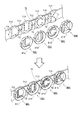
上下動部材72の前部側には、L文字ユニット80L、U文字ユニット80U、C文字ユニット80C、K文字ユニット80K(以下、これらを特に区別しない場合は、まとめて「文字ユニット80L〜K」ともいう)が左右に並べて設けられている。詳しくは後述するが、文字ユニット80L〜Kの後方には、複数のLED71L,71U,71C,71K,71X(LED71)が設けられており、「役物上昇演出」を行う際は、これら複数のLED71を発光させることによって、文字ユニット80L〜Kに表示された文字が発光したように遊技者に感じさせる。これによって、文字ユニット80L〜Kに表示された文字、すなわち、「移動役物70」に表示されたLUCKの文字を目立たせることができ、ひいては、「役物上昇演出」を目立たせることが可能となる。
On the front side of the
次に、文字ユニット80L〜Kについて詳しく説明する。図16には、「移動役物70」を前方からみた分解斜視図が示されている。図16に示すように、上下動部材72の前部側には、LED71L,71U,71C,71K,71X(LED71)が設けられており、これらのLED71に重ねて、文字ユニット80L〜Kが設けられている。文字ユニット80L〜Kは、文字の形状に係る構成を除いては互いに同様の構成を備えている。すなわち、L文字ユニット80Lは、後フレーム81Lと、文字型不透過部材82Lと、文字型シート83Lと、文字型透過部材84Lと、前フレーム85Lとを備え、U文字ユニット80Uは、後フレーム81Uと、文字型不透過部材82Uと、文字型シート83Uと、文字型透過部材84Uと、前フレーム85Uとを備え、C文字ユニット80Cは、後フレーム81Cと、文字型不透過部材82Cと、文字型シート83Cと、文字型透過部材84Cと、前フレーム85Cとを備え、K文字ユニット80Kは、後フレーム81Kと、文字型不透過部材82Kと、文字型シート83Kと、文字型透過部材84Kと、前フレーム85Kとを備えている。
Next, the
以下では、後フレーム81L,81U,81C,81Kを特に区別しない場合は、これらをまとめて「後フレーム81L〜K」とも表現し、文字型不透過部材82L,82U,82C,82Kを特に区別しない場合は、これらをまとめて「文字型不透過部材82L〜K」とも表現し、文字型シート83L,83U,83C,83Kを特に区別しない場合は、これらをまとめて「文字型シート83L〜K」とも表現し、文字型透過部材84L,84U,84C,84Kを特に区別しない場合は、これらをまとめて「文字型透過部材84L〜K」とも表現し、前フレーム85L,85U,85C,85Kを特に区別しない場合は、これらをまとめて「前フレーム85L〜K」とも表現する。
In the following, when the
図17〜図20には、上下動部材72の前部側に文字ユニット80L〜Kが徐々に組み付けられていく様子が示されている。図17に示すように、上下動部材72の前部側には、複数のLED71が発光方向を前方に向けて設けられている。詳しくは、上下動部材72の前部側の領域のうち、L文字ユニット80Lが取り付けられる領域には、前方からみてLの文字に沿って配置された6個のLED71Lと、前方からみてこれらのLED71Lを囲むように配置された6個のLED71Xが配置されている。また、U文字ユニット80Uが取り付けられる領域には、前方からみてUの文字に沿って配置された7個のLED71Uと、前方からみてこれらのLED71Uを囲むように配置された6個のLED71Xが配置されている。また、C文字ユニット80Cが取り付けられる領域には、前方からみてCの文字に沿って配置された9個のLED71Cと、前方からみてこれらのLED71Cを囲むように配置された6個のLED71Xが配置されている。また、K文字ユニット80Kが取り付けられる領域には、前方からみてKの文字に沿って配置された9個のLED71Kと、前方からみてこれらのLED71Kを囲むように配置された6個のLED71Xが配置されている。
17 to 20 show how the
また、上下動部材72の前部側の領域のうち、L文字ユニット80Lが取り付けられる領域とU文字ユニット70Uが取り付けられる領域との間の領域には、光を乱反射させる乱反射板73が取り付けられている。このような乱反射板73は、U文字ユニット80Uが取り付けられる領域とC文字ユニット70Cが取り付けられる領域との間の領域や、C文字ユニット80Cが取り付けられる領域とK文字ユニット70Kが取り付けられる領域との間の領域にも設けられている。
Further, in the area on the front side of the vertical moving
尚、文字に沿って配置されたLED70L,70U,70C,70Kは「発光体」として捉えることもでき、これらのLED70L,70U,70C,70Kを囲むようにして配置されたLED70Xは「別の発光体」として捉えることもでき、乱反射板73は「乱反射部」として捉えることもできる。
The LEDs 70L, 70U, 70C, 70K arranged along the letters can be regarded as "light emitters", and the LEDs 70X arranged so as to surround these LEDs 70L, 70U, 70C, 70K are "another light emitters". The diffused
図17に示すように、上下動部材72の前部側の文字ユニット80L〜Kが取り付けられる領域には、先ず、「後フレーム81L〜K」が取り付けられる。後フレーム81L〜Kは、透明の合成樹脂等の光を透過する材質で形成されており(光を透過するものであり)、前後方向に貫通した貫通孔が設けられている。この貫通孔は、各文字ユニット80L〜Kが表示する文字に対応した形状を有しており、上下動部材72に取り付けられた状態では、該貫通孔に対応する位置に(該貫通孔の後方に)、文字に沿って配置されたLED71が位置する(貫通孔と、文字に沿って配置されたLED71とが前後方向に重なる)。従って、文字ユニット80L〜Kのうち後フレーム81L〜Kのみが取り付けられた状態では、前方から後フレーム81L〜Kの貫通孔を通して、文字に沿って配置されたLED71を視認できるようになっている。詳しくは、後フレーム81Lには、Lの文字に対応した形状の貫通孔が設けられており、該貫通孔に対応する位置に(該貫通孔の後方に)、Lの文字に沿って配置されたLED71Lが位置し、後フレーム81Uには、Uの文字に対応した形状の貫通孔が設けられており、該貫通孔に対応する位置に(該貫通孔の後方に)、Uの文字に沿って配置されたLED71Uが位置し、後フレーム81Cには、Cの文字に対応した形状の貫通孔が設けられており、該貫通孔に対応する位置に(該貫通孔の後方に)、Cの文字に沿って配置されたLED71Cが位置し、後フレーム81Kには、Kの文字に対応した形状の貫通孔が設けられており、該貫通孔に対応する位置に(該貫通孔の後方に)、Kの文字に沿って配置されたLED71Kが位置する。
As shown in FIG. 17, first, the "
また、上述したように、上下動部材72には、文字に沿って配置されたLED71を囲むようにして配置されたLED71X(以下、これらをまとめて「囲繞LED71X」ともいう)も設けられているが、後フレーム81L〜Kの後部側(後面)の各囲繞LED71Xに対応する部位には窪み(収容部)が設けられており、この窪みに囲繞LED71Xが収容されている。
Further, as described above, the
図18に示すように、後フレーム81L〜Kのそれぞれの貫通孔には、「文字型不透過部材82L〜K」が取り付けられている(嵌め込まれている)。文字型不透過部材82L〜Kは、有色の合成樹脂等の光を透過しない材質で形成されており(光を透過しないものであり)、前方からみて、各文字ユニット80L〜Kが表示する文字(後フレーム81L〜Kの貫通孔)に対応した形状を有している。詳しくは、文字型不透過部材82Lは、Lの文字に対応した形状を有しており、文字型不透過部材82Uは、Uの文字に対応した形状を有しており、文字型不透過部材82Cは、Cの文字に対応した形状を有しており、文字型不透過部材82Kは、Kの文字に対応した形状を有している。また、文字型不透過部材82L〜Kには、前後方向に貫通された複数のLED孔が設けられている。これらの文字型不透過部材82L〜KのLED孔は、文字に沿って配置されたLED71に対応する位置に沿って配置されている。そして、文字に沿って配置されたLED71は、それぞれに対応するLED孔に挿入されている。
As shown in FIG. 18, "character type
図19に示すように、後フレーム81L〜Kのそれぞれの貫通孔には、文字型不透過部材82L〜Kに重ねて、「文字型透過部材84L〜K」の後端が挿入されている。文字型透過部材84L〜Kは、透明の合成樹脂等の光を透過する材質で形成されており(光を透過するものであり)、前方からみて、各文字ユニット80L〜Kが表示する文字(後フレーム81L〜Kの貫通孔)に対応した形状を有している。詳しくは、文字型透過部材84Lは、Lの文字に対応した形状を有しており、文字型透過部材84Uは、Uの文字に対応した形状を有しており、文字型透過部材84Cは、Cの文字に対応した形状を有しており、文字型透過部材84Kは、Kの文字に対応した形状を有している。また、文字型透過部材84L〜Kは、後部側が開口した箱状に形成されている(後部側に開口部を有する)。そして、この開口部には、文字に沿って配置されたLED71が対向している(文字型透過部材84L〜Kの開口部と、文字に沿って配置されたLED71とが前後方向に重なる)。従って、文字に沿って配置されたLED71から発せられた光は、文字型透過部材84L〜Kの開口部から文字型透過部材84L〜K内に進入し、文字型透過部材84L〜Kの内部を前方へ(遊技者側へ)進行する。
As shown in FIG. 19, the rear ends of the "character-type
文字型透過部材84L〜Kの内部には、後部側の開口部から「文字型シート83L〜K」が挿入されており、「文字型シート83L〜K」の前面は、文字型透過部材84L〜Kの前壁内面に当接している。また、文字型シート83L〜Kは、前方からみて、各文字ユニット80L〜Kが表示する文字(後フレーム81L〜Kの貫通孔)に対応した形状を有している。詳しくは、文字型シート83Lは、Lの文字に対応した形状を有しており、文字型シート83Uは、Uの文字に対応した形状を有しており、文字型シート83Cは、Cの文字に対応した形状を有しており、文字型シート83Kは、Kの文字に対応した形状を有している。また、文字型シート83L〜Kは、表面に凹凸が形成された透明の合成樹脂等から形成された可撓性を有するシートであり(シート状(薄板状)に形成されており)、後方からの光を透過させつつ拡散させる。従って、文字に沿って配置されたLED71から発せられた光は、文字型透過部材84L〜Kの開口部から文字型透過部材84L〜K内に進入し、文字型シート83L〜Kを透過する際に拡散された後、文字型透過部材84L〜Kの前壁を通過して、文字ユニット80L〜Kの前方へ(遊技者側へ)進行する(抜けていく)。
"
ここで、文字型シート83L〜Kが設けられていなければ、文字に沿って配置されたLED71から発せられた光は、文字型透過部材84L〜Kの開口部から文字型透過部材84L〜K内に進入し、ほとんど拡散されることなく、文字型透過部材84L〜Kの前壁を通過して、文字ユニット80L〜Kの前方へ(遊技者側へ)進行する。従って、遊技者にとっては、文字に沿って配置されたLED71の形状を認識し易くなってしまい(LED71そのものの形状が悪目立ちしてしまい)、文字の存在が希釈化されてしまう。
Here, if the
この点、文字型シート83L〜Kを設けることとすれば、文字に沿って配置されたLED71から発せられた光は、拡散されてから遊技者側に進行する。このため、遊技者にとって文字に沿って配置されたLED71の形状を認識し難くすることができ、且つ、文字全体(文字型透過部材84L〜Kの前壁全体)が発光しているように感じことができる。この結果、文字の存在を際立たせることができ、遊技興趣を高めることが可能となる。
In this regard, if the character-shaped
また、文字に沿って配置されたLED71が発光していない場合は、当該LED71に反射した自然光(環境光)が拡散されることなく、文字型透過部材84L〜Kの前壁を通して、文字ユニット80L〜Kの前方へ(遊技者側へ)進行する。従って、この場合も、遊技者にとっては、文字に沿って配置されたLED71の形状を認識し易くなってしまう(LED71そのものの形状が悪目立ちしてしまう)。そして、この場合、遊技者は、発光していない状態のLED71を見せられることとなるので(ひいては、実際に発光する前に光が発せられることを認識してしまうので)、遊技興趣が低下してしまう虞がある。
When the LED 71 arranged along the character does not emit light, the
この点、文字型シート83L〜Kを設けることとすれば、文字に沿って配置されたLED71に反射した自然光(環境光)は、拡散されてから遊技者側に進行する。このため、遊技者にとって文字に沿って配置されたLED71の形状、ひいては、発光していない状態のLED71の存在を認識し難くすることができ、遊技興趣が低下してしまうことを抑制することが可能となる。
In this regard, if the character-shaped
また、文字型シート83L〜Kは可撓性を有するシートであるので、文字に対応する形状に加工し易く、且つ、文字型シート83L〜Kを容易に文字型透過部材84L〜Kの内部に収容させることができ、生産性を高めることが可能となる。
Further, since the
尚、前壁が文字を模した文字形状に形成されている文字型透過部材84L〜Kは「箱状体」として捉えることもでき、文字型シート83L〜Kは「レンズ部」として捉えることもできる。
The character-shaped
図20に示すように、文字ユニット80L〜Kの前部側には、「前フレーム85L〜K」が設けられている。前フレーム85L〜Kは、有色の合成樹脂等の光を透過しない材質で形成されており(光を透過しないものであり)、前後方向に貫通した貫通孔が設けられている。この貫通孔は、各文字ユニット80L〜Kが表示する文字に対応した形状に形成されており、この貫通孔には、文字型透過部材84L〜Kが挿入されている。詳しくは、前フレーム85Lには、Lの文字に対応した形状の貫通孔が設けられており、該貫通孔には、文字型透過部材84Lが挿入されている。また、前フレーム85Uには、Uの文字に対応した形状の貫通孔が設けられており、該貫通孔には、文字型透過部材84Uが挿入されている。また、前フレーム85Cには、Cの文字に対応した形状の貫通孔が設けられており、該貫通孔には、文字型透過部材84Cが挿入されている。また、前フレーム85Kには、Kの文字に対応した形状の貫通孔が設けられており、該貫通孔には、文字型透過部材84Kが挿入されている。また、前フレーム85L〜Kの前部側には、遊技者が視認可能な模様が形成されている(装飾が施されている)。
As shown in FIG. 20, "front frames 85L to K" are provided on the front side of the
ここで、文字に沿って配置されたLED71から発せられた光が文字型透過部材84L〜K内に進入した後、離反方向(前方からみて文字から離れる方向)に進行してしまうと、文字(文字型透過部材84L〜K)の輪郭がぼやけてしまう虞がある。この点、前フレーム85L〜Kは、光を透過しない材質で形成されており、前フレーム85L〜Kの貫通孔には、文字型透過部材84L〜Kが挿入されている。このため、文字型透過部材84L〜K内から離反方向(前方からみて文字から離れる方向)に進行する光の量を抑えることができる。この結果、文字の輪郭がぼやけてしまうことを抑制することができる。この結果、文字の存在を際立たせることができ、遊技興趣を高めることが可能となる。
Here, when the light emitted from the LED 71 arranged along the character enters the character-
また、前フレーム85L〜Kの(前方からみて)周縁部には、後方に突出した複数の突出部が設けられている。これらの複数の突出部は、後フレーム81L〜Kの外周壁に当接している。詳しくは、これらの複数の突出部は、後フレーム81L〜Kの外周壁であって、囲繞LED71X(図17参照)の位置に対応しない部位に当接している。このため、囲繞LED71から発せられた光は、囲繞LED71Xの位置に対応しない部位(突出部が当接している部位、以下「不透過部位」ともいう)からは離反方向へ進行しないものの、囲繞LED71Xの位置に対応する部位(突出部が当接していない部位、以下「透過部位」ともいう)からは離反方向(放射方向)へ進行することとなる。このため、文字(文字ユニット80L〜K、後フレーム81L〜Kの透過部位)から離反方向(放射方向)に光が出力されることとなる。この結果、遊技者に対して、離反方向(放射方向)に出力された光が文字(文字ユニット80L〜K)を装飾しているように感じさせることができ、ひいては、文字の存在を際立たせることができ、遊技興趣を高めることが可能となる。尚、「透過部位」は「光通過部」として捉えることもできる。
Further, a plurality of projecting portions projecting rearward are provided on the peripheral edge portions (when viewed from the front) of the
また、後フレーム81L〜Kの透過部位のうち互いに対向する部位の間には、当該部位から出力される光を乱反射させる乱反射板73が設けられている。換言すると、当該部位から出力される光の進行方向(離反方向の一部)には、当該光を乱反射させる乱反射板73が設けられている。すなわち、後フレーム81L〜Kの透過部位のうち互いに対向する部位から出力された光が乱反射板73で乱反射するので、遊技者に対して、乱反射板73が発光しているように感じさせることができ、ひいては、乱反射板73が文字(文字ユニット80L〜K)を装飾しているように感じさせることができる。この結果、文字の存在を更に際立たせることができ、遊技興趣を高めることが可能となる。
Further, a diffused
ここで、囲繞LED71Xから発せられた光が離反方向だけでなく、前方へも進行することとなると、離反方向への光の出力が目立たなくなる虞がある。この点、前フレーム85L〜Kの部位が囲繞LED71Xの前方に重なるので、囲繞LED71Xの光が前方へも進行することがなく、離反方向への光の出力が目立たなくなることを抑制することが可能となる。
Here, if the light emitted from the surrounding
尚、前フレーム85L〜Kは「透過抑制部」、「光不透過部」として捉えることもでき、前フレーム85L〜Kの貫通孔は「箱状体収容部」として捉えることもでき、前フレーム85L〜Kの互いに隣り合う突出部の間(後フレーム81L〜Kの透過部位)は「光通過部」として捉えることもできる。また、文字型透過部材84L〜Kの前部側(前壁)および前フレーム85L〜Kの前部側(前壁)は「装飾部」として捉えることもできる。また、文字型透過部材84L〜Kの前部側(前壁)および前フレーム85L〜Kの前部側(前壁)の後方は「装飾部の裏側」として捉えることもでき、また、文字型透過部材84L〜Kの前部側(前壁)および前フレーム85L〜Kの前部側(前壁)の前方は「装飾部の表側」として捉えることもできる。また、文字ユニット80L〜Kのうち隣り合うユニットの文字型透過部材84L〜Kおよび前フレーム85L〜Kは「第1の装飾部」と「第2の装飾部」として捉えることができる。また、前フレーム85L〜Kは「第1の透過抑制部」と「第2の透過抑制部」、あるいは、「第1の光不透過部」と「第2の光不透過部」と捉えることができ、囲繞LED71Xは「第1の発光体」と「第2の発光体」と捉えることができ、前フレーム85L〜Kの互いに隣り合う突出部の間(後フレーム81L〜Kの透過部位)は「第1の光通過部」と「第2の光通過部」と捉えることができる。
The front frames 85L to K can be regarded as a "transmission suppressing portion" and a "light opaque portion", and the through holes of the
以上、本発明の実施例について説明したが、本発明はこれに限定されるものではなく、各請求項に記載した範囲を逸脱しない限り、各請求項の記載文言に限定されず、当業者がそれらから容易に置き換えられる範囲にも及び、かつ、当業者が通常有する知識に基づく改良を適宜付加することができる。 Although the examples of the present invention have been described above, the present invention is not limited to this, and is not limited to the wording described in each claim as long as it does not deviate from the scope described in each claim, and those skilled in the art can use it. Improvements based on the knowledge usually possessed by those skilled in the art can be added as appropriate to the extent that they can be easily replaced.
例えば、上述した実施例では、囲繞LED71Xから発せられた光が離反方向へ出力されることとした。これに限らず、前フレーム85L〜Kの側壁に光が通過する間隙を設け、文字に沿って配置されたLED71から発せられた光が文字型透過部材84L〜K内に進入した後、当該間隙を通過して離反方向(前方からみて文字から離れる方向)に進行するようにしてもよい。
For example, in the above-described embodiment, the light emitted from the surrounding
また、上述した実施例では、遊技ホールの島設備から供給される遊技球を払い出すことによって、遊技の結果としての利益(遊技価値)を遊技者に付与するパチンコ機1に本発明を適用した例を説明した。これに限らず、「遊技球の払い出し」とは異なる形態で遊技上の利益を付与するタイプの遊技機にも、本発明を適用することができる。例えば、各種入球口への遊技球の入球が発生することで、その入球に対応する利益の量(遊技価値の大きさ)を示すデータを記憶することによって、遊技上の利益(遊技価値)を遊技者に付与するタイプのパチンコ機にも本発明を適用することができ、この場合にも、上述した実施例と同様の効果を得ることができる。なお、遊技上の利益(遊技価値)をデータ化して遊技者に付与するタイプのパチンコ機としては、パチンコ機に内蔵された複数個の遊技球を循環させて使用する遊技機、具体的には、各種入球口あるいはアウト口を経て遊技盤の裏面に排出された遊技球を、再度、発射位置に戻して発射するように構成されたパチンコ機(いわゆる封入式遊技機)を例示できる。
Further, in the above-described embodiment, the present invention is applied to the
<上述した実施例から抽出できる遊技機A1〜A8>
上述した実施例のパチンコ機は、次のような遊技機A1〜A8として捉えることもできる。
<Game machines A1 to A8 that can be extracted from the above-mentioned examples>
The pachinko machines of the above-described embodiment can also be regarded as the following game machines A1 to A8.
<遊技機A1>
遊技盤に形成された遊技領域に向けて遊技球を発射することによって遊技を行う遊技機であって、
装飾が施された装飾部と、
前記装飾部の裏側に位置する発光体と、
を備える
ことを特徴とする遊技機。
<Game machine A1>
A gaming machine that plays a game by firing a gaming ball toward a gaming area formed on a gaming board.
The decorated part and the decoration
A luminous body located on the back side of the decorative portion and
A gaming machine characterized by being equipped with.
<遊技機A2>
遊技機A1において、
前記装飾部の裏側には、前記発光体の光を、前記装飾部の表側からみて前記装飾部から離れる方向に通過させる光通過部が設けられている
ことを特徴とする遊技機。
<Game machine A2>
In the gaming machine A1
A gaming machine characterized in that a light passing portion is provided on the back side of the decorative portion to allow light of the light emitting body to pass in a direction away from the decorative portion when viewed from the front side of the decorative portion.
このような遊技機では、「装飾部の表側からみて装飾部から離れる方向」に光が出力される。この結果、遊技者に対して、「装飾部の表側からみて装飾部から離れる方向」に出力された光が装飾部を装飾しているように感じさせることができ、ひいては、装飾部の存在を際立たせることができ、遊技興趣を高めることが可能となる。 In such a gaming machine, light is output in the "direction away from the decorative portion when viewed from the front side of the decorative portion". As a result, it is possible to make the player feel that the light output in the "direction away from the decoration part when viewed from the front side of the decoration part" is decorating the decoration part, and by extension, the existence of the decoration part. It can be made to stand out, and it is possible to enhance the interest of the game.
<遊技機A3>
遊技機A2において、
前記光通過部は、前記装飾部の表側からみて前記装飾部の周縁に沿って複数が設けられている
ことを特徴とする遊技機。
<Game machine A3>
In the gaming machine A2
A gaming machine characterized in that a plurality of the light passing portions are provided along the peripheral edge of the decorative portion when viewed from the front side of the decorative portion.
このような遊技機では、装飾部から複数の「装飾部の表側からみて装飾部から離れる方向」(放射方向)に光が出力される。この結果、遊技者に対して、更に、「装飾部の表側からみて装飾部から離れる方向」に出力された光が装飾部を装飾しているように感じさせることができ、ひいては、装飾部の存在を更に際立たせることができ、遊技興趣を高めることが可能となる。 In such a gaming machine, light is output from the decorative portion in a plurality of "directions away from the decorative portion when viewed from the front side of the decorative portion" (radiation direction). As a result, the player can be made to feel that the light output in the "direction away from the decoration part when viewed from the front side of the decoration part" further decorates the decoration part, and by extension, the decoration part. The existence can be further emphasized, and it becomes possible to enhance the entertainment of the game.
<遊技機A4>
遊技機A2または遊技機A3において、
前記装飾部には、前記装飾の少なくとも一部として、文字が表示されている
ことを特徴とする遊技機。
<Game machine A4>
In the gaming machine A2 or the gaming machine A3
A gaming machine characterized in that characters are displayed on the decorative portion as at least a part of the decoration.
装飾として文字が表示されている遊技機では、当該文字を遊技者に認識させることによって遊技興趣を高めることができるところ、遊技機A4では、「装飾部の表側からみて装飾部から離れる方向」に光が出力される。この結果、遊技者に対して、「装飾部の表側からみて装飾部から離れる方向」に出力された光が文字を装飾しているように感じさせることができ、ひいては、文字の存在を際立たせることができ、遊技興趣を高めることが可能となる。 In a gaming machine in which characters are displayed as decorations, it is possible to enhance the interest of the game by making the player recognize the characters. Light is output. As a result, the player can be made to feel that the light output in the "direction away from the decoration part when viewed from the front side of the decoration part" is decorating the character, and by extension, the presence of the character is emphasized. It is possible to enhance the entertainment of the game.
<遊技機A5>
遊技機A4において、
前記装飾部の表側からみて前記装飾部の前記文字の周囲の部位は、前記発光体の光を前記装飾部の表側へ透過させない
ことを特徴とする遊技機。
<Game machine A5>
In the gaming machine A4
A gaming machine characterized in that a portion of the decorative portion around the characters when viewed from the front side of the decorative portion does not transmit the light of the light emitter to the front side of the decorative portion.
文字の周囲の部位から装飾部の表側へ光が透過すると、該光によって文字の輪郭がぼやけて見える虞がある。この点、遊技機A5では、文字の周囲の部位は、発光体の光を装飾部の表側へ透過させないので、文字の輪郭がぼやけて見えるのを抑制しつつ、「装飾部の表側からみて装飾部から離れる方向」に光が出力される。この結果、文字を認識し易くさせつつ、文字の存在を際立たせることができ、遊技興趣を高めることが可能となる。 When light is transmitted from a portion around the character to the front side of the decorative portion, the outline of the character may appear blurred due to the light. In this regard, in the gaming machine A5, since the light of the light emitting body is not transmitted to the front side of the decorative part in the part around the character, the outline of the character is suppressed from appearing blurry, and "decoration when viewed from the front side of the decorative part". Light is output in the direction away from the part. As a result, it is possible to make the existence of the character stand out while making it easier to recognize the character, and it is possible to enhance the interest of the game.
<遊技機A6>
遊技機A2乃至遊技機A5の何れか1つの遊技機において、
少なくとも一部の前記光通過部の、前記装飾部の表側からみて前記装飾部から離れる方向には、該光通過部を通過した前記発光体の光を乱反射させる乱反射部が設けられている
ことを特徴とする遊技機。
<Game machine A6>
In any one of the gaming machines A2 to A5,
At least a part of the light passing portion is provided with a diffused reflecting portion that diffusely reflects the light of the light emitting body that has passed through the light passing portion in a direction away from the decorative portion when viewed from the front side of the decorative portion. A featured gaming machine.
このような遊技機では、「装飾部の表側からみて装飾部から離れる方向」に出力された光が乱反射部で乱反射するので、遊技者に対して、乱反射部が発光しているように感じさせることができ、ひいては、乱反射部が装飾部を装飾しているように感じさせることができる。この結果、装飾部の存在を更に際立たせることができ、遊技興趣を高めることが可能となる。
<遊技機A7>
遊技機A6において、
前記装飾部として、第1の装飾部と第2の装飾部とを備え、
前記発光体として、前記第1の装飾部の裏側に位置する第1の発光体と、前記第2の装飾部の裏側に位置する第2の発光体とを備え、
前記第1の装飾部の裏側には、前記第1の発光体の光を、前記第1の装飾部の表側からみて前記第1の装飾部から離れる方向に通過させる第1の光通過部が前記光通過部として設けられ、
前記第2の装飾部の裏側には、前記第2の発光体の光を、前記第2の装飾部の表側からみて前記第2の装飾部から離れる方向に通過させる第2の光通過部が前記光通過部として設けられ、
前記第1の光通過部の少なくとも一部と前記第2の光通過部の少なくとも一部とは、互いに対向して設けられており、
前記乱反射部は、互いに対向する前記第1の光通過部と前記第2の光通過部との間に設けられている
ことを特徴とする遊技機。
In such a gaming machine, the light output in the direction away from the decorative portion when viewed from the front side of the decorative portion is diffusely reflected by the diffused reflecting portion, so that the player feels that the diffused reflecting portion is emitting light. This can make the diffused reflection part feel as if it is decorating the decorative part. As a result, the existence of the decorative part can be further emphasized, and the game entertainment can be enhanced.
<Game machine A7>
In the game machine A6
As the decorative portion, a first decorative portion and a second decorative portion are provided.
The light emitting body includes a first light emitting body located on the back side of the first decorative portion and a second light emitting body located on the back side of the second decorative portion.
On the back side of the first decorative portion, there is a first light passing portion that allows the light of the first light emitting body to pass in a direction away from the first decorative portion when viewed from the front side of the first decorative portion. Provided as the light passing portion,
On the back side of the second decorative portion, there is a second light passing portion that allows the light of the second light emitting body to pass in a direction away from the second decorative portion when viewed from the front side of the second decorative portion. Provided as the light passing portion,
At least a part of the first light passing portion and at least a part of the second light passing portion are provided so as to face each other.
A gaming machine characterized in that the diffused reflecting portion is provided between the first light passing portion and the second light passing portion facing each other.
このような遊技機では、第1の装飾部から「第1の装飾部の表側からみて第1の装飾部から離れる方向」に出力された光と、第2の装飾部から「第2の装飾部の表側からみて第2の装飾部から離れる方向」に出力された光との両方が乱反射部で乱反射するので、遊技者に対して、乱反射部が更に強く発光しているように感じさせることができ、ひいては、第1の装飾部および第2の装飾部に挟まれた乱反射部がこれらの装飾部を装飾しているように感じさせることができる。この結果、第1の装飾部および第2の装飾部の存在を更に際立たせることができ、遊技興趣を高めることが可能となる。 In such a gaming machine, the light output from the first decorative portion in the direction "away from the first decorative portion when viewed from the front side of the first decorative portion" and the light output from the second decorative portion in the "second decoration". Since both the light output in the direction away from the second decorative part when viewed from the front side of the part is diffusely reflected by the diffused reflection part, the player is made to feel that the diffused reflection part is emitting more intense light. As a result, it is possible to make the diffused reflection portion sandwiched between the first decorative portion and the second decorative portion feel as if they are decorating these decorative portions. As a result, the existence of the first decorative portion and the second decorative portion can be further emphasized, and the game entertainment can be enhanced.
<遊技機A8>
遊技機A2乃至遊技機A7の何れか1つの遊技機において、
前記装飾部の少なくとも一部は、光透過性を有しており、前記発光体の光を発散させながら透過させる
ことを特徴とする遊技機。
<Game machine A8>
In any one of the gaming machines A2 to A7,
A gaming machine characterized in that at least a part of the decorative portion has light transmission and transmits light of the light emitting body while diverging it.
このような遊技機では、発光体を発光させることによって、「装飾部の表側からみて装飾部から離れる方向」に光が出力されるだけでなく、装飾部の少なくとも一部が発光しているように遊技者に認識させることができる。この結果、この結果、装飾部の存在を更に際立たせることができ、遊技興趣を高めることが可能となる。 In such a gaming machine, by making the light emitting body emit light, not only the light is output in the direction away from the decorative part when viewed from the front side of the decorative part, but also at least a part of the decorative part seems to emit light. Can be recognized by the player. As a result, as a result, the existence of the decorative portion can be further emphasized, and the game entertainment can be enhanced.
<上述した実施例から抽出できる遊技機B1〜B8>
上述した実施例のパチンコ機は、次のような遊技機B1〜B8として捉えることもできる。
<Game machines B1 to B8 that can be extracted from the above-mentioned examples>
The pachinko machines of the above-described embodiment can also be regarded as the following game machines B1 to B8.
<遊技機B1>
遊技盤に形成された遊技領域に向けて遊技球を発射することによって遊技を行う遊技機であって、
装飾が施された装飾部と、
前記装飾部の裏側に位置する発光体と、
を備え、
前記発光体は、所定の演出の実行中に発光する
ことを特徴とする遊技機。
<Game machine B1>
A gaming machine that plays a game by firing a gaming ball toward a gaming area formed on a gaming board.
The decorated part and the decoration
A luminous body located on the back side of the decorative portion and
With
The light emitting body is a gaming machine characterized in that it emits light during execution of a predetermined effect.
<遊技機B2>
遊技機B1において、
前記装飾部の裏側には、前記発光体の光を、前記装飾部の表側からみて前記装飾部から離れる方向に通過させる光通過部が設けられている
ことを特徴とする遊技機。
<Game machine B2>
In the gaming machine B1
A gaming machine characterized in that a light passing portion is provided on the back side of the decorative portion to allow light of the light emitting body to pass in a direction away from the decorative portion when viewed from the front side of the decorative portion.
このような遊技機では、「装飾部の表側からみて装飾部から離れる方向」に光が出力される。この結果、遊技者に対して、「装飾部の表側からみて装飾部から離れる方向」に出力された光が装飾部を装飾しているように感じさせることができ、ひいては、装飾部の存在を際立たせることができ、遊技興趣を高めることが可能となる。 In such a gaming machine, light is output in the "direction away from the decorative portion when viewed from the front side of the decorative portion". As a result, it is possible to make the player feel that the light output in the "direction away from the decoration part when viewed from the front side of the decoration part" is decorating the decoration part, and by extension, the existence of the decoration part. It can be made to stand out, and it is possible to enhance the interest of the game.
<遊技機B3>
遊技機B2において、
前記光通過部は、前記装飾部の表側からみて前記装飾部の周縁に沿って複数が設けられている
ことを特徴とする遊技機。
<Game machine B3>
In the gaming machine B2
A gaming machine characterized in that a plurality of the light passing portions are provided along the peripheral edge of the decorative portion when viewed from the front side of the decorative portion.
このような遊技機では、装飾部から複数の「装飾部の表側からみて装飾部から離れる方向」(放射方向)に光が出力される。この結果、遊技者に対して、更に、「装飾部の表側からみて装飾部から離れる方向」に出力された光が装飾部を装飾しているように感じさせることができ、ひいては、装飾部の存在を更に際立たせることができ、遊技興趣を高めることが可能となる。 In such a gaming machine, light is output from the decorative portion in a plurality of "directions away from the decorative portion when viewed from the front side of the decorative portion" (radiation direction). As a result, the player can be made to feel that the light output in the "direction away from the decoration part when viewed from the front side of the decoration part" further decorates the decoration part, and by extension, the decoration part. The existence can be further emphasized, and it becomes possible to enhance the entertainment of the game.
<遊技機B4>
遊技機B2または遊技機B3において、
前記装飾部には、前記装飾の少なくとも一部として、文字が表示されている
ことを特徴とする遊技機。
<Game machine B4>
In the gaming machine B2 or the gaming machine B3
A gaming machine characterized in that characters are displayed on the decorative portion as at least a part of the decoration.
装飾として文字が表示されている遊技機では、当該文字を遊技者に認識させることによって遊技興趣を高めることができるところ、遊技機A4では、「装飾部の表側からみて装飾部から離れる方向」に光が出力される。この結果、遊技者に対して、「装飾部の表側からみて装飾部から離れる方向」に出力された光が文字を装飾しているように感じさせることができ、ひいては、文字の存在を際立たせることができ、遊技興趣を高めることが可能となる。 In a gaming machine in which characters are displayed as decorations, it is possible to enhance the interest of the game by making the player recognize the characters. Light is output. As a result, the player can be made to feel that the light output in the "direction away from the decoration part when viewed from the front side of the decoration part" is decorating the character, and by extension, the presence of the character is emphasized. It is possible to enhance the entertainment of the game.
<遊技機B5>
遊技機B4において、
前記装飾部の表側からみて前記装飾部の前記文字の周囲の部位は、前記発光体の光を前記装飾部の表側へ透過させない
ことを特徴とする遊技機。
<Game machine B5>
In the gaming machine B4
A gaming machine characterized in that a portion of the decorative portion around the characters when viewed from the front side of the decorative portion does not transmit the light of the light emitter to the front side of the decorative portion.
文字の周囲の部位から装飾部の表側へ光が透過すると、該光によって文字の輪郭がぼやけて見える虞がある。この点、遊技機A5では、文字の周囲の部位は、発光体の光を装飾部の表側へ透過させないので、文字の輪郭がぼやけて見えるのを抑制しつつ、「装飾部の表側からみて装飾部から離れる方向」に光が出力される。この結果、文字を認識し易くさせつつ、文字の存在を際立たせることができ、遊技興趣を高めることが可能となる。 When light is transmitted from a portion around the character to the front side of the decorative portion, the outline of the character may appear blurred due to the light. In this regard, in the gaming machine A5, since the light of the light emitting body is not transmitted to the front side of the decorative part in the part around the character, the outline of the character is suppressed from appearing blurry, and "decoration when viewed from the front side of the decorative part". Light is output in the direction away from the part. As a result, it is possible to make the existence of the character stand out while making it easier to recognize the character, and it is possible to enhance the interest of the game.
<遊技機B6>
遊技機B2乃至遊技機B5の何れか1つの遊技機において、
少なくとも一部の前記光通過部の、前記装飾部の表側からみて前記装飾部から離れる方向には、該光通過部を通過した前記発光体の光を乱反射させる乱反射部が設けられている
ことを特徴とする遊技機。
<Game machine B6>
In any one of the gaming machines B2 to the gaming machine B5,
At least a part of the light passing portion is provided with a diffused reflecting portion that diffusely reflects the light of the light emitting body that has passed through the light passing portion in a direction away from the decorative portion when viewed from the front side of the decorative portion. A featured gaming machine.
このような遊技機では、「装飾部の表側からみて装飾部から離れる方向」に出力された光が乱反射部で乱反射するので、遊技者に対して、乱反射部が発光しているように感じさせることができ、ひいては、乱反射部が装飾部を装飾しているように感じさせることができる。この結果、装飾部の存在を更に際立たせることができ、遊技興趣を高めることが可能となる。
<遊技機B7>
遊技機B6において、
前記装飾部として、第1の装飾部と第2の装飾部とを備え、
前記発光体として、前記第1の装飾部の裏側に位置する第1の発光体と、前記第2の装飾部の裏側に位置する第2の発光体とを備え、
前記第1の装飾部の裏側には、前記第1の発光体の光を、前記第1の装飾部の表側からみて前記第1の装飾部から離れる方向に通過させる第1の光通過部が前記光通過部として設けられ、
前記第2の装飾部の裏側には、前記第2の発光体の光を、前記第2の装飾部の表側からみて前記第2の装飾部から離れる方向に通過させる第2の光通過部が前記光通過部として設けられ、
前記第1の光通過部の少なくとも一部と前記第2の光通過部の少なくとも一部とは、互いに対向して設けられており、
前記乱反射部は、互いに対向する前記第1の光通過部と前記第2の光通過部との間に設けられている
ことを特徴とする遊技機。
In such a gaming machine, the light output in the direction away from the decorative portion when viewed from the front side of the decorative portion is diffusely reflected by the diffused reflecting portion, so that the player feels that the diffused reflecting portion is emitting light. This can make the diffused reflection part feel as if it is decorating the decorative part. As a result, the existence of the decorative part can be further emphasized, and the game entertainment can be enhanced.
<Game machine B7>
In the gaming machine B6
As the decorative portion, a first decorative portion and a second decorative portion are provided.
The light emitting body includes a first light emitting body located on the back side of the first decorative portion and a second light emitting body located on the back side of the second decorative portion.
On the back side of the first decorative portion, there is a first light passing portion that allows the light of the first light emitting body to pass in a direction away from the first decorative portion when viewed from the front side of the first decorative portion. Provided as the light passing portion,
On the back side of the second decorative portion, there is a second light passing portion that allows the light of the second light emitting body to pass in a direction away from the second decorative portion when viewed from the front side of the second decorative portion. Provided as the light passing portion,
At least a part of the first light passing portion and at least a part of the second light passing portion are provided so as to face each other.
A gaming machine characterized in that the diffused reflecting portion is provided between the first light passing portion and the second light passing portion facing each other.
このような遊技機では、第1の装飾部から「第1の装飾部の表側からみて第1の装飾部から離れる方向」に出力された光と、第2の装飾部から「第2の装飾部の表側からみて第2の装飾部から離れる方向」に出力された光との両方が乱反射部で乱反射するので、遊技者に対して、乱反射部が更に強く発光しているように感じさせることができ、ひいては、第1の装飾部および第2の装飾部に挟まれた乱反射部がこれらの装飾部を装飾しているように感じさせることができる。この結果、第1の装飾部および第2の装飾部の存在を更に際立たせることができ、遊技興趣を高めることが可能となる。 In such a gaming machine, the light output from the first decorative portion in the direction "away from the first decorative portion when viewed from the front side of the first decorative portion" and the light output from the second decorative portion in the "second decoration". Since both the light output in the direction away from the second decorative part when viewed from the front side of the part is diffusely reflected by the diffused reflection part, the player is made to feel that the diffused reflection part is emitting more intense light. As a result, it is possible to make the diffused reflection portion sandwiched between the first decorative portion and the second decorative portion feel as if they are decorating these decorative portions. As a result, the existence of the first decorative portion and the second decorative portion can be further emphasized, and the game entertainment can be enhanced.
<遊技機B8>
遊技機B2乃至遊技機B7の何れか1つの遊技機において、
前記装飾部の少なくとも一部は、光透過性を有しており、前記発光体の光を発散させながら透過させる
ことを特徴とする遊技機。
<Game machine B8>
In any one of the gaming machines B2 to the gaming machine B7,
A gaming machine characterized in that at least a part of the decorative portion has light transmission and transmits light of the light emitting body while diverging it.
このような遊技機では、発光体を発光させることによって、「装飾部の表側からみて装飾部から離れる方向」に光が出力されるだけでなく、装飾部の少なくとも一部が発光しているように遊技者に認識させることができる。この結果、この結果、装飾部の存在を更に際立たせることができ、遊技興趣を高めることが可能となる。 In such a gaming machine, by making the light emitting body emit light, not only the light is output in the direction away from the decorative part when viewed from the front side of the decorative part, but also at least a part of the decorative part seems to emit light. Can be recognized by the player. As a result, as a result, the existence of the decorative portion can be further emphasized, and the game entertainment can be enhanced.
<上述した実施例から抽出できる遊技機C1〜C11>
上述した実施例のパチンコ機は、次のような遊技機C1〜C11として捉えることもできる。
<Game machines C1 to C11 that can be extracted from the above-mentioned examples>
The pachinko machines of the above-described embodiment can also be regarded as the following game machines C1 to C11.
<遊技機C1>
遊技盤の前部側に形成された遊技領域に向けて遊技球を発射することによって遊技を行う遊技機であって、
光を透過させる光透過部と、
発光方向を前記光透過部に向けて設けられた発光体と、
を備える
ことを特徴とする遊技機。
<Game machine C1>
A gaming machine that plays a game by firing a gaming ball toward a gaming area formed on the front side of the gaming board.
A light transmitting part that transmits light and
A light emitting body provided with a light emitting direction directed toward the light transmitting portion, and
A gaming machine characterized by being equipped with.
<遊技機C2>
遊技盤の前部側に形成された遊技領域に向けて遊技球を発射することによって遊技を行う遊技機であって、
後部側が開口した箱状に形成されると共に、少なくとも前壁は後方からの光を透過させる光透過性を有する箱状体と、
前記箱状体の前記前壁の後方に、発光方向を該前壁に向けて設けられた発光体と、
を備える
ことを特徴とする遊技機。
<Game machine C2>
A gaming machine that plays a game by firing a gaming ball toward a gaming area formed on the front side of the gaming board.
A box-shaped body with an open rear side, and at least the front wall has a light-transmitting light-transmitting body that allows light from the rear to pass through.
A light emitting body provided behind the front wall of the box-shaped body with the light emitting direction directed toward the front wall, and
A gaming machine characterized by being equipped with.
このような遊技機では、発光体から発せられた光は、箱状体の内部を進行して前壁に到達するところ、一部の光は箱状体の内壁面に反射しながら前壁に到達する。例えば、内壁が光透過性を有していても、一部の(少しの)光は箱状体の内壁面に反射しながら前壁に到達する。このため、前壁に到達する光の量を大きくすることができ、ひいては、遊技者に対して、前壁が発光しているように感じさせやすくなる(前壁を目立たせることができる)。この結果、遊技興趣を高めることが可能となる。 In such a gaming machine, the light emitted from the light emitting body travels inside the box-shaped body and reaches the front wall, and some of the light is reflected on the inner wall surface of the box-shaped body and reaches the front wall. To reach. For example, even if the inner wall has light transmission, some (a little) light reaches the front wall while being reflected by the inner wall surface of the box-shaped body. Therefore, the amount of light reaching the front wall can be increased, and by extension, the player can easily feel that the front wall is emitting light (the front wall can be made to stand out). As a result, it is possible to enhance the game entertainment.
<遊技機C3>
遊技機C2において、
前記箱状体の前記前壁と前記発光体との間には、後方からの光を透過させつつ拡散させるレンズ部が設けられている
ことを特徴とする遊技機。
<Game machine C3>
In the gaming machine C2
A gaming machine characterized in that a lens portion for transmitting and diffusing light from the rear is provided between the front wall of the box-shaped body and the light emitting body.
このような遊技機では、発光体から発せられた光は、レンズ部によって拡散されてから遊技者側に進行する。このため、発光体の形状を認識し難くすることができ、且つ、前壁全体が発光しているように感じさせることができる。この結果、前壁の存在を際立たせることができ、遊技興趣を高めることが可能となる。また、発光体が発光していない場合は、発光体に反射した自然光(環境光)は、レンズ部によって拡散されてから遊技者側に進行する。このため、遊技者にとって発光体の形状、ひいては、発光していない状態の発光体の存在を認識し難くすることができ、遊技興趣が低下してしまうことを抑制することが可能となる。 In such a gaming machine, the light emitted from the light emitting body is diffused by the lens unit and then proceeds to the player side. Therefore, it is possible to make it difficult to recognize the shape of the light emitting body, and it is possible to make the entire front wall feel as if it is emitting light. As a result, the existence of the front wall can be emphasized, and the game entertainment can be enhanced. When the light emitting body does not emit light, the natural light (ambient light) reflected by the light emitting body is diffused by the lens unit and then proceeds to the player side. Therefore, it is possible for the player to make it difficult for the player to recognize the shape of the light emitting body and, by extension, the existence of the light emitting body in a state where the light emitting body is not emitting light, and it is possible to suppress the deterioration of the game interest.
<遊技機C4>
遊技機C2において、
前記箱状体の前記前壁は、前方からみて文字を模した文字形状に形成されている
ことを特徴とする遊技機。
<Game machine C4>
In the gaming machine C2
A gaming machine characterized in that the front wall of the box-shaped body is formed in a character shape imitating a character when viewed from the front.
このような遊技機では、前方からみて文字形状の前壁が発光しているように感じさせることができるので、該文字形状(文字)を目立たせることができ、遊技興趣を高めることが可能となる。 In such a gaming machine, since the front wall of the character shape can be made to feel as if it is emitting light when viewed from the front, the character shape (character) can be made to stand out, and it is possible to enhance the game interest. Become.
<遊技機C5>
遊技機C4において、
複数の前記発光体が設けられており、
該複数の前記発光体は、前記文字形状に沿って配置されている
ことを特徴とする遊技機。
<Game machine C5>
In the gaming machine C4
A plurality of the above-mentioned light emitters are provided,
A gaming machine characterized in that the plurality of the light emitters are arranged along the character shape.
このような遊技機では、箱状体の文字形状に沿って複数の発光体が配置されているので、発光体から発せられた光を文字形状の前壁全体に到達させ易くなる。例えば、複雑な文字を模した文字形状の前壁であっても、該前壁全体に光を到達させ易くなる。この結果、遊技者に対して、前壁の文字形状(文字)全体が発光しているように感じさせることができ、ひいては、前壁の文字形状(文字)を認識し易くさせることが可能となる。 In such a gaming machine, since a plurality of light emitting bodies are arranged along the character shape of the box-shaped body, it becomes easy for the light emitted from the light emitting bodies to reach the entire front wall of the character shape. For example, even if the front wall has a character shape that imitates a complicated character, it becomes easy for light to reach the entire front wall. As a result, it is possible to make the player feel that the entire character shape (character) of the front wall is emitting light, and by extension, it is possible to make it easier to recognize the character shape (character) of the front wall. Become.
<遊技機C6>
遊技機C4または遊技機C5において、
前記箱状体の前部側に設けられた前記透過部と前記光発光体との間には、前方からみて前記文字形状に形成され、且つ、後方からの光を透過させつつ拡散させるレンズ部が設けられている
ことを特徴とする遊技機。
<Game machine C6>
In the gaming machine C4 or the gaming machine C5
A lens portion formed in the character shape when viewed from the front and diffuses light from the rear while transmitting between the transmitting portion provided on the front side of the box-shaped body and the light emitting body. A game machine characterized by being provided with.
このような遊技機では、発光体から発せられた光は、レンズ部によって拡散されてから遊技者側に進行する。このため、発光体の形状を認識し難くすることができ、且つ、文字形状の前壁全体が発光しているように感じさせることができる。この結果、文字形状の前壁(文字)の存在を際立たせることができ、遊技興趣を高めることが可能となる。また、発光体が発光していない場合は、発光体に反射した自然光(環境光)は、レンズ部によって拡散されてから遊技者側に進行する。このため、遊技者にとって発光体の形状、ひいては、発光していない状態の発光体の存在を認識し難くすることができ、遊技興趣が低下してしまうことを抑制することが可能となる。 In such a gaming machine, the light emitted from the light emitting body is diffused by the lens unit and then proceeds to the player side. Therefore, it is possible to make it difficult to recognize the shape of the light emitting body, and it is possible to make the entire front wall of the character shape feel as if it is emitting light. As a result, the existence of the front wall (character) of the character shape can be emphasized, and the game entertainment can be enhanced. When the light emitting body does not emit light, the natural light (ambient light) reflected by the light emitting body is diffused by the lens unit and then proceeds to the player side. Therefore, it is possible for the player to make it difficult for the player to recognize the shape of the light emitting body and, by extension, the existence of the light emitting body in a state where the light emitting body is not emitting light, and it is possible to suppress the deterioration of the game interest.
<遊技機C7>
遊技機C3または遊技機C6の遊技機において、
前記レンズ部は、可撓性を有するシート状に形成されている
ことを特徴とする遊技機。
<Game machine C7>
In the gaming machine of the gaming machine C3 or the gaming machine C6
A gaming machine characterized in that the lens portion is formed in the form of a flexible sheet.
このような遊技機では、レンズ部が可撓性を有するシート状に形成されているので、レンズ部を所定の形状に加工し易く、且つ、レンズ部を容易に箱状体の内部に収容させることができる。この結果、生産性を高めることが可能となる。特に、前壁が文字形状である場合は、レンズ部も文字形状であるので、レンズ部が複雑な形状になり易い。このような場合であっても、レンズ部が可撓性を有するシート状に形成されていれば、レンズ部を文字形状に加工し易く、且つ、レンズ部を容易に箱状体の内部に収容させることができ、生産性を高めることが可能となる。 In such a gaming machine, since the lens portion is formed in a flexible sheet shape, the lens portion can be easily processed into a predetermined shape, and the lens portion can be easily accommodated inside the box-shaped body. be able to. As a result, it becomes possible to increase productivity. In particular, when the front wall has a character shape, the lens portion also has a character shape, so that the lens portion tends to have a complicated shape. Even in such a case, if the lens portion is formed in a flexible sheet shape, the lens portion can be easily processed into a character shape, and the lens portion can be easily housed inside the box-shaped body. It is possible to increase productivity.
<遊技機C8>
遊技機C2乃至遊技機C7の何れか1つの遊技機において、
前記透過部より光を透過させる量が少ない透過抑制部を備え、
前記透過抑制部には、前後方向に貫通した箱状体収容部が形成されており、
前記箱状体は、前記透過抑制部の前記箱状体収容部に収容されている
ことを特徴とする遊技機。
<Game machine C8>
In any one of the gaming machines C2 to the gaming machine C7,
A transmission suppressing unit that transmits light less than the transmitting unit is provided.
A box-shaped body accommodating portion penetrating in the front-rear direction is formed in the permeation suppressing portion.
A gaming machine characterized in that the box-shaped body is housed in the box-shaped body accommodating portion of the permeation suppressing portion.
発光体から発せられた光が箱状体内に進入した後、離反方向(前方からみて箱状体の前壁から離れる方向)に進行してしまうと、前壁の輪郭がぼやけてしまう虞がある。この点、箱状体は、透過抑制部の箱状体収容部に収容されており、透過抑制部は光を透過させる量が少ないので、箱状体内から離反方向(前方からみて文字から離れる方向)に進行する光の量を抑えることができる。このため、箱状体の前壁の輪郭がぼやけてしまうことを抑制することができる。特に、箱状体の前壁が文字形状である場合は、発光体から発せられた光が箱状体内に進入した後、離反方向(前方からみて箱状体の前壁から離れる方向)に進行してしまうと、文字形状(文字)の輪郭がぼやけてしまう虞がある。この点、箱状体内から離反方向(前方からみて文字から離れる方向)に進行する光の量を抑えることとすると、文字形状(文字)の輪郭がぼやけてしまうことを抑制することができる。この結果、文字の存在を際立たせることができ、遊技興趣を高めることが可能となる。 If the light emitted from the illuminant enters the box-shaped body and then travels in the direction of separation (the direction away from the front wall of the box-shaped body when viewed from the front), the outline of the front wall may be blurred. .. In this respect, the box-shaped body is housed in the box-shaped body accommodating portion of the transmission suppressing portion, and the transmission suppressing portion transmits a small amount of light. ) Can suppress the amount of light that travels. Therefore, it is possible to prevent the outline of the front wall of the box-shaped body from being blurred. In particular, when the front wall of the box-shaped body has a character shape, the light emitted from the illuminant enters the box-shaped body and then travels in the direction of separation (the direction away from the front wall of the box-shaped body when viewed from the front). If this is done, the outline of the character shape (character) may be blurred. In this respect, if the amount of light traveling in the direction away from the box-shaped body (the direction away from the characters when viewed from the front) is suppressed, it is possible to suppress blurring of the outline of the character shape (characters). As a result, the existence of the characters can be emphasized, and the game entertainment can be enhanced.
<遊技機C9>
遊技機C8において、
前記発光体とは別の発光体を備え、
前記別の発光体は、前記透過抑制部の後方側に設けられており、
前記透過抑制部の後方には、前記別の発光体の光を、前方からみて前記箱状体から離れる方向である離反方向に通過させる間隙が設けられている
ことを特徴とする遊技機。
<Game machine C9>
In the gaming machine C8
A light emitting body different from the light emitting body is provided, and the light emitting body is provided.
The other light emitting body is provided on the rear side of the transmission suppressing portion, and is provided.
A gaming machine characterized in that a gap is provided behind the transmission suppressing portion to allow light from another light emitting body to pass in a direction away from the box-shaped body when viewed from the front.
このような遊技機では、前方からみて箱状体から離れる方向である離反方向に光が出力される。この結果、遊技者に対して、離反方向に出力された光が箱状体(前壁が文字形状である場合は文字)を装飾しているように感じさせることができ、ひいては、箱状体(前壁が文字形状である場合は文字)の存在を際立たせることができ、遊技興趣を高めることが可能となる。 In such a gaming machine, light is output in the direction of separation, which is the direction away from the box-shaped body when viewed from the front. As a result, the player can be made to feel that the light output in the separation direction decorates the box-shaped body (characters when the front wall has a character shape), and by extension, the box-shaped body. The presence of (characters when the front wall is in the shape of characters) can be emphasized, and it is possible to enhance the interest of the game.
<遊技機C10>
遊技機C9において、
前記間隙は、前方からみて前記箱状体を囲むようにして複数が設けられている
ことを特徴とする遊技機。
<Game machine C10>
In the gaming machine C9
A gaming machine characterized in that a plurality of the gaps are provided so as to surround the box-shaped body when viewed from the front.
このような遊技機では、箱状体(前壁が文字形状である場合は文字)から複数の離反方向(放射方向)に光が出力される。この結果、遊技者に対して、更に、離反方向(放射方向)に出力された光が箱状体(前壁が文字形状である場合は文字)を装飾しているように感じさせることができ、ひいては、箱状体(前壁が文字形状である場合は文字)の存在を更に際立たせることができ、遊技興趣を高めることが可能となる。 In such a gaming machine, light is output from a box-shaped body (characters when the front wall has a character shape) in a plurality of separation directions (radiation directions). As a result, the player can be made to feel that the light output in the separation direction (radiation direction) is further decorating the box-shaped body (characters when the front wall has a character shape). As a result, the existence of the box-shaped body (characters when the front wall has a character shape) can be further emphasized, and the game entertainment can be enhanced.
<遊技機C11>
遊技機C9または遊技機C10において、
少なくとも一部の前記間隙の前記離反方向には、該間隙を通過した前記別の発光体の光を乱反射させる乱反射部が設けられている
ことを特徴とする遊技機。
<Game machine C11>
In the gaming machine C9 or the gaming machine C10
A gaming machine characterized in that at least a part of the gap in the separation direction is provided with a diffuse reflection portion that diffusely reflects the light of the other light emitting body that has passed through the gap.
このような遊技機では、箱状体(前壁が文字形状である場合は文字)から離反方向に出力された光が乱反射部で乱反射するので、遊技者に対して、乱反射部が発光しているように感じさせることができ、ひいては、乱反射部が(前壁が文字形状である場合は文字)を装飾しているように感じさせることができる。この結果、文字の存在を更に際立たせることができ、遊技興趣を高めることが可能となる。 In such a gaming machine, the light output in the direction away from the box-shaped body (characters when the front wall has a character shape) is diffusely reflected by the diffused reflection unit, so that the diffused reflection unit emits light to the player. It can be made to feel as if it is, and by extension, it can be made to feel that the diffused reflection portion (characters when the front wall has a character shape) is decorated. As a result, the existence of the characters can be further emphasized, and the game entertainment can be enhanced.
本発明は、遊技ホールで用いられる遊技機に利用することができる。 The present invention can be used for a gaming machine used in a gaming hall.
1…パチンコ機(遊技機)、20…遊技盤、40…演出用開口部、41…演出表示装置、60…裏パック、60a…表示画面用開口部、70…移動役物、71L,U,C,K,X…LED(発光体、別の発光体)、72…上下動部材、80L〜K…文字ユニット、81L〜K…後フレーム、82L〜K…文字型不透過部材、83L〜K…文字型シート(レンズ部)、84L〜K…文字型透過部材(箱状体、装飾部)、85L〜K…前フレーム(透過抑制部、光不透過部、装飾部)。 1 ... Pachinko machine (game machine), 20 ... Game board, 40 ... Production opening, 41 ... Production display device, 60 ... Back pack, 60a ... Display screen opening, 70 ... Mobile accessory, 71L, U, C, K, X ... LED (light emitting body, another light emitting body), 72 ... Vertical movement member, 80L to K ... Character unit, 81L to K ... Rear frame, 82L to K ... Character type opaque member, 83L to K ... Character type sheet (lens part), 84L to K ... Character type transmitting member (box-shaped body, decorative part), 85L to K ... Front frame (transmission suppressing part, light impervious part, decorative part).
Claims (1)
表側に文字が表示された文字ユニットと、
前記文字ユニットの裏側に位置する発光体と、
を備え、
前記文字ユニットには、表側からみて当該文字ユニットから離れる方向に前記発光体の光を透過させる透過部位が複数設けられており、
前記文字ユニットとして、第1文字ユニットと第2文字ユニットとを備えており、
前記第1文字ユニットの前記透過部位の一部と、前記第2文字ユニットの前記透過部位の一部とは互いに対向しており、
前記互いに対向している前記透過部位の間には、当該互いに対向している前記透過部位を透過する前記発光体の光を乱反射させる乱反射部が設けられている
ことを特徴とする遊技機。 A gaming machine that plays a game by firing a gaming ball toward a gaming area formed on a gaming board.
A character unit with characters displayed on the front side and
A light emitter located on the back side of the character unit and
With
The character unit is provided with a plurality of transmission portions for transmitting the light of the light emitting body in a direction away from the character unit when viewed from the front side .
The character unit includes a first character unit and a second character unit.
A part of the transparent part of the first character unit and a part of the transparent part of the second character unit face each other.
A gaming machine characterized in that a diffused reflecting portion for diffusely reflecting the light of the light emitting body transmitted through the transmitting portions facing each other is provided between the transmitting portions facing each other .
Priority Applications (2)
| Application Number | Priority Date | Filing Date | Title |
|---|---|---|---|
| JP2017045039A JP6945834B2 (en) | 2017-03-09 | 2017-03-09 | Pachinko machine |
| JP2021146063A JP2021184879A (en) | 2017-03-09 | 2021-09-08 | Game machine |
Applications Claiming Priority (1)
| Application Number | Priority Date | Filing Date | Title |
|---|---|---|---|
| JP2017045039A JP6945834B2 (en) | 2017-03-09 | 2017-03-09 | Pachinko machine |
Related Child Applications (1)
| Application Number | Title | Priority Date | Filing Date |
|---|---|---|---|
| JP2021146063A Division JP2021184879A (en) | 2017-03-09 | 2021-09-08 | Game machine |
Publications (3)
| Publication Number | Publication Date |
|---|---|
| JP2018143716A JP2018143716A (en) | 2018-09-20 |
| JP2018143716A5 JP2018143716A5 (en) | 2020-04-23 |
| JP6945834B2 true JP6945834B2 (en) | 2021-10-06 |
Family
ID=63590270
Family Applications (2)
| Application Number | Title | Priority Date | Filing Date |
|---|---|---|---|
| JP2017045039A Active JP6945834B2 (en) | 2017-03-09 | 2017-03-09 | Pachinko machine |
| JP2021146063A Pending JP2021184879A (en) | 2017-03-09 | 2021-09-08 | Game machine |
Family Applications After (1)
| Application Number | Title | Priority Date | Filing Date |
|---|---|---|---|
| JP2021146063A Pending JP2021184879A (en) | 2017-03-09 | 2021-09-08 | Game machine |
Country Status (1)
| Country | Link |
|---|---|
| JP (2) | JP6945834B2 (en) |
Family Cites Families (4)
| Publication number | Priority date | Publication date | Assignee | Title |
|---|---|---|---|---|
| JP4305711B2 (en) * | 2001-01-26 | 2009-07-29 | 株式会社大一商会 | Amusement machine lighting equipment |
| JP2004016645A (en) * | 2002-06-19 | 2004-01-22 | Sankyo Kk | Pinball game machine and slot machine |
| JP5199843B2 (en) * | 2008-11-20 | 2013-05-15 | 株式会社ニューギン | Game machine |
| JP5788277B2 (en) * | 2011-09-16 | 2015-09-30 | 株式会社藤商事 | Bullet ball machine |
-
2017
- 2017-03-09 JP JP2017045039A patent/JP6945834B2/en active Active
-
2021
- 2021-09-08 JP JP2021146063A patent/JP2021184879A/en active Pending
Also Published As
| Publication number | Publication date |
|---|---|
| JP2018143716A (en) | 2018-09-20 |
| JP2021184879A (en) | 2021-12-09 |
Similar Documents
| Publication | Publication Date | Title |
|---|---|---|
| JP2006288738A (en) | Game machine | |
| JP2022040252A (en) | Game machine | |
| JP2018143704A (en) | Game machine | |
| JP6212738B1 (en) | Game machine | |
| JP6945834B2 (en) | Pachinko machine | |
| JP6945835B2 (en) | Pachinko machine | |
| JP6908911B2 (en) | Pachinko machine | |
| JP7006895B2 (en) | Pachinko machine | |
| JP2021168998A (en) | Game machine | |
| JP6842774B2 (en) | Game machine | |
| JP6355173B2 (en) | Game machine | |
| JP7006916B2 (en) | Pachinko machine | |
| JP7054162B2 (en) | Pachinko machine | |
| JP6846043B2 (en) | Game machine | |
| JP7429963B2 (en) | gaming machine | |
| JP2018143712A (en) | Game machine | |
| JP6188104B1 (en) | Game machine | |
| JP6871615B2 (en) | Game machine | |
| JP2022041628A (en) | Game machine | |
| JP6685489B2 (en) | Amusement machine | |
| JP2021083942A (en) | Game machine | |
| JP6403138B2 (en) | Game machine | |
| JP2023044502A (en) | game machine | |
| JP2021074251A (en) | Game machine | |
| JP2022039728A (en) | Game machine |
Legal Events
| Date | Code | Title | Description |
|---|---|---|---|
| A521 | Written amendment |
Free format text: JAPANESE INTERMEDIATE CODE: A523 Effective date: 20200309 |
|
| A621 | Written request for application examination |
Free format text: JAPANESE INTERMEDIATE CODE: A621 Effective date: 20200309 |
|
| A977 | Report on retrieval |
Free format text: JAPANESE INTERMEDIATE CODE: A971007 Effective date: 20201211 |
|
| A131 | Notification of reasons for refusal |
Free format text: JAPANESE INTERMEDIATE CODE: A131 Effective date: 20201222 |
|
| A521 | Written amendment |
Free format text: JAPANESE INTERMEDIATE CODE: A523 Effective date: 20210218 |
|
| TRDD | Decision of grant or rejection written | ||
| A01 | Written decision to grant a patent or to grant a registration (utility model) |
Free format text: JAPANESE INTERMEDIATE CODE: A01 Effective date: 20210810 |
|
| A61 | First payment of annual fees (during grant procedure) |
Free format text: JAPANESE INTERMEDIATE CODE: A61 Effective date: 20210908 |
|
| R150 | Certificate of patent or registration of utility model |
Ref document number: 6945834 Country of ref document: JP Free format text: JAPANESE INTERMEDIATE CODE: R150 |