JP6943580B2 - Non-aqueous electrolyte secondary battery separator - Google Patents
Non-aqueous electrolyte secondary battery separator Download PDFInfo
- Publication number
- JP6943580B2 JP6943580B2 JP2017041086A JP2017041086A JP6943580B2 JP 6943580 B2 JP6943580 B2 JP 6943580B2 JP 2017041086 A JP2017041086 A JP 2017041086A JP 2017041086 A JP2017041086 A JP 2017041086A JP 6943580 B2 JP6943580 B2 JP 6943580B2
- Authority
- JP
- Japan
- Prior art keywords
- secondary battery
- aqueous electrolyte
- porous film
- separator
- electrolyte secondary
- Prior art date
- Legal status (The legal status is an assumption and is not a legal conclusion. Google has not performed a legal analysis and makes no representation as to the accuracy of the status listed.)
- Active
Links
Images

Classifications
-
- H—ELECTRICITY
- H01—ELECTRIC ELEMENTS
- H01M—PROCESSES OR MEANS, e.g. BATTERIES, FOR THE DIRECT CONVERSION OF CHEMICAL ENERGY INTO ELECTRICAL ENERGY
- H01M50/00—Constructional details or processes of manufacture of the non-active parts of electrochemical cells other than fuel cells, e.g. hybrid cells
- H01M50/40—Separators; Membranes; Diaphragms; Spacing elements inside cells
- H01M50/409—Separators, membranes or diaphragms characterised by the material
- H01M50/449—Separators, membranes or diaphragms characterised by the material having a layered structure
-
- H—ELECTRICITY
- H01—ELECTRIC ELEMENTS
- H01M—PROCESSES OR MEANS, e.g. BATTERIES, FOR THE DIRECT CONVERSION OF CHEMICAL ENERGY INTO ELECTRICAL ENERGY
- H01M10/00—Secondary cells; Manufacture thereof
- H01M10/05—Accumulators with non-aqueous electrolyte
-
- H—ELECTRICITY
- H01—ELECTRIC ELEMENTS
- H01M—PROCESSES OR MEANS, e.g. BATTERIES, FOR THE DIRECT CONVERSION OF CHEMICAL ENERGY INTO ELECTRICAL ENERGY
- H01M10/00—Secondary cells; Manufacture thereof
- H01M10/05—Accumulators with non-aqueous electrolyte
- H01M10/052—Li-accumulators
-
- H—ELECTRICITY
- H01—ELECTRIC ELEMENTS
- H01M—PROCESSES OR MEANS, e.g. BATTERIES, FOR THE DIRECT CONVERSION OF CHEMICAL ENERGY INTO ELECTRICAL ENERGY
- H01M50/00—Constructional details or processes of manufacture of the non-active parts of electrochemical cells other than fuel cells, e.g. hybrid cells
- H01M50/40—Separators; Membranes; Diaphragms; Spacing elements inside cells
- H01M50/409—Separators, membranes or diaphragms characterised by the material
- H01M50/411—Organic material
- H01M50/414—Synthetic resins, e.g. thermoplastics or thermosetting resins
- H01M50/417—Polyolefins
-
- H—ELECTRICITY
- H01—ELECTRIC ELEMENTS
- H01M—PROCESSES OR MEANS, e.g. BATTERIES, FOR THE DIRECT CONVERSION OF CHEMICAL ENERGY INTO ELECTRICAL ENERGY
- H01M50/00—Constructional details or processes of manufacture of the non-active parts of electrochemical cells other than fuel cells, e.g. hybrid cells
- H01M50/40—Separators; Membranes; Diaphragms; Spacing elements inside cells
- H01M50/409—Separators, membranes or diaphragms characterised by the material
- H01M50/411—Organic material
- H01M50/414—Synthetic resins, e.g. thermoplastics or thermosetting resins
- H01M50/423—Polyamide resins
-
- H—ELECTRICITY
- H01—ELECTRIC ELEMENTS
- H01M—PROCESSES OR MEANS, e.g. BATTERIES, FOR THE DIRECT CONVERSION OF CHEMICAL ENERGY INTO ELECTRICAL ENERGY
- H01M50/00—Constructional details or processes of manufacture of the non-active parts of electrochemical cells other than fuel cells, e.g. hybrid cells
- H01M50/40—Separators; Membranes; Diaphragms; Spacing elements inside cells
- H01M50/409—Separators, membranes or diaphragms characterised by the material
- H01M50/443—Particulate material
-
- H—ELECTRICITY
- H01—ELECTRIC ELEMENTS
- H01M—PROCESSES OR MEANS, e.g. BATTERIES, FOR THE DIRECT CONVERSION OF CHEMICAL ENERGY INTO ELECTRICAL ENERGY
- H01M50/00—Constructional details or processes of manufacture of the non-active parts of electrochemical cells other than fuel cells, e.g. hybrid cells
- H01M50/40—Separators; Membranes; Diaphragms; Spacing elements inside cells
- H01M50/46—Separators, membranes or diaphragms characterised by their combination with electrodes
-
- H—ELECTRICITY
- H01—ELECTRIC ELEMENTS
- H01M—PROCESSES OR MEANS, e.g. BATTERIES, FOR THE DIRECT CONVERSION OF CHEMICAL ENERGY INTO ELECTRICAL ENERGY
- H01M50/00—Constructional details or processes of manufacture of the non-active parts of electrochemical cells other than fuel cells, e.g. hybrid cells
- H01M50/40—Separators; Membranes; Diaphragms; Spacing elements inside cells
- H01M50/463—Separators, membranes or diaphragms characterised by their shape
-
- H—ELECTRICITY
- H01—ELECTRIC ELEMENTS
- H01M—PROCESSES OR MEANS, e.g. BATTERIES, FOR THE DIRECT CONVERSION OF CHEMICAL ENERGY INTO ELECTRICAL ENERGY
- H01M50/00—Constructional details or processes of manufacture of the non-active parts of electrochemical cells other than fuel cells, e.g. hybrid cells
- H01M50/40—Separators; Membranes; Diaphragms; Spacing elements inside cells
- H01M50/489—Separators, membranes, diaphragms or spacing elements inside the cells, characterised by their physical properties, e.g. swelling degree, hydrophilicity or shut down properties
-
- H—ELECTRICITY
- H01—ELECTRIC ELEMENTS
- H01M—PROCESSES OR MEANS, e.g. BATTERIES, FOR THE DIRECT CONVERSION OF CHEMICAL ENERGY INTO ELECTRICAL ENERGY
- H01M50/00—Constructional details or processes of manufacture of the non-active parts of electrochemical cells other than fuel cells, e.g. hybrid cells
- H01M50/50—Current conducting connections for cells or batteries
- H01M50/572—Means for preventing undesired use or discharge
- H01M50/584—Means for preventing undesired use or discharge for preventing incorrect connections inside or outside the batteries
-
- H—ELECTRICITY
- H01—ELECTRIC ELEMENTS
- H01M—PROCESSES OR MEANS, e.g. BATTERIES, FOR THE DIRECT CONVERSION OF CHEMICAL ENERGY INTO ELECTRICAL ENERGY
- H01M10/00—Secondary cells; Manufacture thereof
- H01M10/05—Accumulators with non-aqueous electrolyte
- H01M10/052—Li-accumulators
- H01M10/0525—Rocking-chair batteries, i.e. batteries with lithium insertion or intercalation in both electrodes; Lithium-ion batteries
-
- H—ELECTRICITY
- H01—ELECTRIC ELEMENTS
- H01M—PROCESSES OR MEANS, e.g. BATTERIES, FOR THE DIRECT CONVERSION OF CHEMICAL ENERGY INTO ELECTRICAL ENERGY
- H01M2300/00—Electrolytes
- H01M2300/0017—Non-aqueous electrolytes
-
- H—ELECTRICITY
- H01—ELECTRIC ELEMENTS
- H01M—PROCESSES OR MEANS, e.g. BATTERIES, FOR THE DIRECT CONVERSION OF CHEMICAL ENERGY INTO ELECTRICAL ENERGY
- H01M50/00—Constructional details or processes of manufacture of the non-active parts of electrochemical cells other than fuel cells, e.g. hybrid cells
- H01M50/40—Separators; Membranes; Diaphragms; Spacing elements inside cells
- H01M50/403—Manufacturing processes of separators, membranes or diaphragms
- H01M50/406—Moulding; Embossing; Cutting
-
- Y—GENERAL TAGGING OF NEW TECHNOLOGICAL DEVELOPMENTS; GENERAL TAGGING OF CROSS-SECTIONAL TECHNOLOGIES SPANNING OVER SEVERAL SECTIONS OF THE IPC; TECHNICAL SUBJECTS COVERED BY FORMER USPC CROSS-REFERENCE ART COLLECTIONS [XRACs] AND DIGESTS
- Y02—TECHNOLOGIES OR APPLICATIONS FOR MITIGATION OR ADAPTATION AGAINST CLIMATE CHANGE
- Y02E—REDUCTION OF GREENHOUSE GAS [GHG] EMISSIONS, RELATED TO ENERGY GENERATION, TRANSMISSION OR DISTRIBUTION
- Y02E60/00—Enabling technologies; Technologies with a potential or indirect contribution to GHG emissions mitigation
- Y02E60/10—Energy storage using batteries
Description
本発明は、非水電解液二次電池用セパレータ、非水電解液二次電池用積層セパレータ、非水電解液二次電池用部材および非水電解液二次電池に関する。 The present invention relates to a separator for a non-aqueous electrolyte secondary battery, a laminated separator for a non-aqueous electrolyte secondary battery, a member for a non-aqueous electrolyte secondary battery, and a non-aqueous electrolyte secondary battery.
リチウム二次電池等の非水電解液二次電池は、現在、パーソナルコンピュータ、携帯電話および携帯情報端末等の機器に用いる電池、または車載用の電池として広く使用されている。 Non-aqueous electrolyte secondary batteries such as lithium secondary batteries are currently widely used as batteries used in devices such as personal computers, mobile phones and mobile information terminals, or batteries for vehicles.
このような非水電解液二次電池におけるセパレータとしては、例えば特許文献1に記載されるような、ポリオレフィンを主成分とする多孔質フィルムが知られている。 As a separator in such a non-aqueous electrolytic solution secondary battery, for example, a porous film containing polyolefin as a main component, as described in Patent Document 1, is known.
しかしながら、従来技術は、サイクル後の抵抗増加率の抑制が十分ではなく、改善の余地があった。 However, in the prior art, the suppression of the resistance increase rate after the cycle is not sufficient, and there is room for improvement.
本発明の一態様は、このような問題点に鑑みなされたものであって、充放電サイクル後の電池抵抗増加が抑制された非水電解液二次電池用セパレータを実現することを目的とする。 One aspect of the present invention has been made in view of such problems, and an object of the present invention is to realize a separator for a non-aqueous electrolyte secondary battery in which an increase in battery resistance after a charge / discharge cycle is suppressed. ..
本発明の一態様に係る非水電解液二次電池用セパレータは、ポリオレフィン多孔質フィルムを含む非水電解液二次電池用セパレータであって、上記ポリオレフィン多孔質フィルムのTDを長手方向とした試験片を用いて、JIS P 8115(1994)に規定されたMIT試験機法によって測定された、上記試験片の長手方向の長さが2.4cm変化するまでの折り曲げ回数が1600回以上である。 The separator for a non-aqueous electrolytic solution secondary battery according to one aspect of the present invention is a separator for a non-aqueous electrolytic solution secondary battery containing a polyolefin porous film, and a test in which the TD of the polyolefin porous film is in the longitudinal direction. Using the piece, the number of times of bending until the length of the test piece in the longitudinal direction changes by 2.4 cm or more as measured by the MIT testing machine method specified in JIS P 8115 (1994) is 1600 times or more.
本発明の一態様に係る非水電解液二次電池用セパレータは、上記多孔質フィルムのMDを長手方向とした試験片を用いて、JIS P 8115(1994)に規定されたMIT試験機法によって測定された、5000回折り曲げた場合の上記試験片の長手方向の長さの、折り曲げ1回あたりの変化量が0.0004mm/回以上であることが好ましい。 The separator for a non-aqueous electrolyte secondary battery according to one aspect of the present invention uses a test piece having the MD of the porous film in the longitudinal direction, and is subjected to the MIT testing machine method specified in JIS P 8115 (1994). It is preferable that the amount of change in the length of the test piece in the longitudinal direction when bent by 5000 times per bending is 0.0004 mm / time or more.
本発明の一態様に係る非水電解液二次電池用積層セパレータは、本発明の一態様に係る非水電解液二次電池用セパレータと絶縁性多孔質層とを備える。 The laminated separator for a non-aqueous electrolytic solution secondary battery according to one aspect of the present invention includes a separator for a non-aqueous electrolytic solution secondary battery according to an aspect of the present invention and an insulating porous layer.
本発明の一態様に係る非水電解液二次電池用部材は、正極と、本発明の一態様に係る非水電解液二次電池用セパレータ、または非水電解液二次電池用積層セパレータと、負極とがこの順で配置されてなる。 The member for a non-aqueous electrolyte secondary battery according to one aspect of the present invention includes a positive electrode, a separator for a non-aqueous electrolyte secondary battery according to an aspect of the present invention, or a laminated separator for a non-aqueous electrolyte secondary battery. , The negative electrode and the negative electrode are arranged in this order.
本発明の一態様に係る非水電解液二次電池は、本発明の一態様に係る非水電解液二次電池用セパレータ、または非水電解液二次電池用積層セパレータを備える。 The non-aqueous electrolytic solution secondary battery according to one aspect of the present invention includes a separator for a non-aqueous electrolytic solution secondary battery according to an aspect of the present invention, or a laminated separator for a non-aqueous electrolytic solution secondary battery.
本発明の一態様によれば、充放電サイクル後の電池抵抗増加を抑制できるという効果を奏する。 According to one aspect of the present invention, it is possible to suppress an increase in battery resistance after a charge / discharge cycle.
本発明の一実施形態について以下に説明するが、本発明はこれに限定されるものではない。本発明は、以下に説明する各構成に限定されるものではなく、特許請求の範囲に示した範囲で種々の変更が可能であり、異なる実施形態にそれぞれ開示された技術的手段を適宜組み合わせて得られる実施形態についても本発明の技術的範囲に含まれる。なお、本明細書において特記しない限り、数値範囲を表す「A〜B」は、「A以上B以下」を意味する。 An embodiment of the present invention will be described below, but the present invention is not limited thereto. The present invention is not limited to the configurations described below, and various modifications can be made within the scope of the claims, and the technical means disclosed in the different embodiments may be appropriately combined. The obtained embodiments are also included in the technical scope of the present invention. Unless otherwise specified in the present specification, "A to B" representing a numerical range means "A or more and B or less".
〔1.非水電解液二次電池用セパレータ〕
本発明の一実施形態に係る非水電解液二次電池用セパレータは、ポリオレフィン多孔質フィルムを含む非水電解液二次電池用セパレータであって、上記ポリオレフィン多孔質フィルムのTDを長手方向とした試験片を用いて、JIS P 8115(1994)に規定されたMIT試験機法によって測定された、上記試験片の長手方向の長さが2.4cm変化するまでの折り曲げ回数が1600回以上である。
[1. Non-aqueous electrolyte secondary battery separator]
The separator for a non-aqueous electrolyte secondary battery according to an embodiment of the present invention is a separator for a non-aqueous electrolyte secondary battery containing a polyolefin porous film, and the TD of the polyolefin porous film is in the longitudinal direction. Using the test piece, the number of times of bending until the length of the test piece in the longitudinal direction changes by 2.4 cm or more as measured by the MIT testing machine method specified in JIS P 8115 (1994) is 1600 times or more. ..
なお、本明細書において、ポリオレフィン多孔質フィルムのことを単に多孔質フィルムということがある。また、本明細書において、多孔質フィルムのMD(Machine Direction)とは、多孔質フィルムの製造時の搬送方向を意図している。また、多孔質フィルムのTD(Transverse Direction)とは、多孔質フィルムのMDに垂直な方向を意図している。 In addition, in this specification, a polyolefin porous film may be simply referred to as a porous film. Further, in the present specification, the MD (Machine Direction) of the porous film is intended to be the transport direction at the time of manufacturing the porous film. Further, the TD (Transverse Direction) of the porous film is intended to be a direction perpendicular to the MD of the porous film.
<ポリオレフィン多孔質フィルム>
本発明の一実施形態に係る非水電解液二次電池用セパレータは、ポリオレフィン多孔質フィルムを含み、好ましくはポリオレフィン多孔質フィルムからなる。多孔質フィルムは、その内部に連結した細孔を多数有しており、一方の面から他方の面に気体および液体を通過させることが可能となっている。上記多孔質フィルムは、非水電解液二次電池用セパレータ、または後述する非水電解液二次電池用積層セパレータの基材となり得る。多孔質フィルムは、電池が発熱したときに溶融して非水電解液二次電池用セパレータを無孔化することにより、当該非水電解液二次電池用セパレータにシャットダウン機能を付与するものであり得る。
<Polyolefin porous film>
The separator for a non-aqueous electrolytic solution secondary battery according to an embodiment of the present invention contains a polyolefin porous film, preferably made of a polyolefin porous film. The porous film has a large number of pores connected to the inside thereof, and it is possible to allow gas and liquid to pass from one surface to the other. The porous film can be a base material for a separator for a non-aqueous electrolyte secondary battery or a laminated separator for a non-aqueous electrolyte secondary battery, which will be described later. The porous film melts when the battery generates heat to make the separator for the non-aqueous electrolyte secondary battery non-porous, thereby imparting a shutdown function to the separator for the non-aqueous electrolyte secondary battery. obtain.
ここで、「ポリオレフィン多孔質フィルム」とは、ポリオレフィン系樹脂を主成分とする多孔質フィルムである。また、「ポリオレフィン系樹脂を主成分とする」とは、多孔質フィルムに占めるポリオレフィン系樹脂の割合が、多孔質フィルムを構成する材料全体の50体積%以上、好ましくは90体積%以上であり、より好ましくは95体積%以上であることを意味する。 Here, the "polyolefin porous film" is a porous film containing a polyolefin-based resin as a main component. Further, "mainly composed of a polyolefin resin" means that the ratio of the polyolefin resin to the porous film is 50% by volume or more, preferably 90% by volume or more of the whole material constituting the porous film. More preferably, it means that it is 95% by volume or more.
上記多孔質フィルムの主成分であるポリオレフィン系樹脂は、特に限定されないが、例えば、熱可塑性樹脂である、エチレン、プロピレン、1−ブテン、4−メチル−1−ペンテンおよび/または1−ヘキセン等の単量体が重合されてなる単独重合体および共重合体が挙げられる。即ち、単独重合体としては、ポリエチレン、ポリプロピレンおよびポリブテン等、共重合体としてはエチレン−プロピレン共重合体等が挙げられる。多孔質フィルムは、これらのポリオレフィン系樹脂を単独にて含む層、または、これらのポリオレフィン系樹脂の2種以上を含む層であり得る。このうち、過大電流が流れることをより低温で阻止(シャットダウン)することができるため、ポリエチレンがより好ましく、特に、エチレンを主体とする高分子量のポリエチレンが好ましい。なお、多孔質フィルムは、当該層の機能を損なわない範囲で、ポリオレフィン以外の成分を含むことを妨げない。 The polyolefin-based resin that is the main component of the porous film is not particularly limited, and is, for example, a thermoplastic resin such as ethylene, propylene, 1-butene, 4-methyl-1-pentene and / or 1-hexene. Examples thereof include homopolymers and copolymers obtained by polymerizing monomers. That is, examples of the homopolymer include polyethylene, polypropylene and polybutene, and examples of the copolymer include ethylene-propylene copolymer. The porous film may be a layer containing these polyolefin resins alone, or a layer containing two or more of these polyolefin resins. Of these, polyethylene is more preferable because it can prevent (shut down) the flow of an excessive current at a lower temperature, and polyethylene having a high molecular weight mainly composed of ethylene is particularly preferable. The porous film does not prevent the inclusion of components other than polyolefin as long as the function of the layer is not impaired.
ポリエチレンとしては、低密度ポリエチレン、高密度ポリエチレン、線状ポリエチレン(エチレン−α−オレフィン共重合体)および超高分子量ポリエチレン等が挙げられる。このうち、超高分子量ポリエチレンがさらに好ましく、重量平均分子量が5×10⁵〜15×106の高分子量成分が含まれていることがさらに好ましい。特に、ポリオレフィン系樹脂に重量平均分子量が100万以上の高分子量成分が含まれていると、多孔質フィルムおよび非水電解液二次電池用積層セパレータの強度が向上するのでより好ましい。 Examples of polyethylene include low-density polyethylene, high-density polyethylene, linear polyethylene (ethylene-α-olefin copolymer), ultra-high molecular weight polyethylene and the like. Among them, more preferably ultra high molecular weight polyethylene, more preferably a weight average molecular weight are included high molecular weight component of 5 × 10 5 ~15 × 10 6 . In particular, it is more preferable that the polyolefin resin contains a high molecular weight component having a weight average molecular weight of 1 million or more because the strength of the porous film and the laminated separator for a non-aqueous electrolyte secondary battery is improved.
多孔質フィルムの厚さは、4〜40μmであることが好ましく、5〜20μmであることがより好ましい。多孔質フィルムの厚さが4μm以上であると、電池の内部短絡を十分に防止することができるため、好ましい。一方、多孔質フィルムの厚さが40μm以下であると、非水電解液二次電池の大型化を防ぐことができるため、好ましい。 The thickness of the porous film is preferably 4 to 40 μm, more preferably 5 to 20 μm. When the thickness of the porous film is 4 μm or more, it is preferable because the internal short circuit of the battery can be sufficiently prevented. On the other hand, when the thickness of the porous film is 40 μm or less, it is possible to prevent the non-aqueous electrolyte secondary battery from becoming large in size, which is preferable.
多孔質フィルムの単位面積当たりの重量目付は、電池の重量エネルギー密度および体積エネルギー密度を高くすることができるように、通常、4〜20g/m2であることが好ましく、5〜12g/m2であることがより好ましい。 Fabric weight per unit area of the porous film, to be able to increase the weight energy density and volume energy density of the battery, usually, it is preferably 4~20g / m 2, 5~12g / m 2 Is more preferable.
多孔質フィルムの透気度は、ガーレ値で30〜500sec/100mLであることが好ましく、50〜300sec/100mLであることがより好ましい。これにより、非水電解液二次電池用セパレータが十分なイオン透過性を得ることができる。 The air permeability of the porous film is preferably 30 to 500 sec / 100 mL, and more preferably 50 to 300 sec / 100 mL in terms of Gale value. As a result, the separator for a non-aqueous electrolyte secondary battery can obtain sufficient ion permeability.
多孔質フィルムの空隙率は、20〜80体積%であることが好ましく、30〜75体積%であることがより好ましい。これにより、電解液の保持量を高めると共に、過大電流が流れることをより低温で確実に阻止(シャットダウン)することができる。 The porosity of the porous film is preferably 20 to 80% by volume, more preferably 30 to 75% by volume. As a result, the holding amount of the electrolytic solution can be increased, and the flow of an excessive current can be reliably prevented (shut down) at a lower temperature.
多孔質フィルムが有する細孔の孔径は、0.3μm以下であることが好ましく、0.14μm以下であることがより好ましい。これにより、十分なイオン透過性を得ることができ、かつ、電極を構成する粒子の入り込みを、より防止することができる。 The pore size of the pores of the porous film is preferably 0.3 μm or less, and more preferably 0.14 μm or less. As a result, sufficient ion permeability can be obtained, and the entry of particles constituting the electrode can be further prevented.
上記多孔質フィルムは、TDの強度が特定の範囲である。この強度は、多孔質フィルムのTDを長手方向とした試験片を用いて、JIS P 8115(1994)に規定されたMIT試験機法によって測定された、折り曲げ回数によって特定することができる。上記試験片の長手方向の長さが2.4cm変化するまでの折り曲げ回数が1600回以上であることが好ましく、2000回以上であることがより好ましく、2500回以上であることがさらに好ましい。また、当該折り曲げ回数は40000回以下であることが好ましく、35000回以下であることがより好ましく、30000回以下であることがさらに好ましい。 The porous film has a TD strength in a specific range. This strength can be specified by the number of bends measured by the MIT tester method specified in JIS P 8115 (1994) using a test piece in which the TD of the porous film is in the longitudinal direction. The number of times of bending until the length of the test piece in the longitudinal direction changes by 2.4 cm is preferably 1600 times or more, more preferably 2000 times or more, and further preferably 2500 times or more. Further, the number of times of bending is preferably 40,000 times or less, more preferably 35,000 times or less, and further preferably 30,000 times or less.
上記折り曲げ回数は、多孔質フィルムのTDにおける伸びやすさを反映している。上記折り曲げ回数が1600回以上であることは、多孔質フィルムがTDにおいて、ある程度伸び難いことを表している。これにより、セパレータの皺、または内部構造の変形が生じ難く、それゆえに電池抵抗の増加を抑えることができる。 The number of times of bending reflects the ease of stretching of the porous film in TD. The fact that the number of times of bending is 1600 or more indicates that the porous film is difficult to stretch to some extent in TD. As a result, wrinkles of the separator or deformation of the internal structure are unlikely to occur, and therefore an increase in battery resistance can be suppressed.
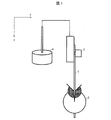
図1は、MIT試験機法に用いられるMIT試験機の概略を示す模式図である。x軸は水平方向を表し、y軸は鉛直方向を表す。MIT試験機法の概要を以下に説明する。試験片1の長手方向の一端をばね荷重クランプ2で挟み、もう一端を折り曲げクランプ3で挟んで固定する。ばね荷重クランプ2は錘4とつながっている。これにより試験片1は、長手方向にテンションがかかった状態となる。この状態において、試験片1の長手方向は鉛直方向と平行である。そして、折り曲げクランプ3を回転させることにより、試験片1を折り曲げる。
FIG. 1 is a schematic view showing an outline of a MIT testing machine used in the MIT testing machine method. The x-axis represents the horizontal direction and the y-axis represents the vertical direction. The outline of the MIT testing machine method will be described below. One end of the test piece 1 in the longitudinal direction is sandwiched between the spring load clamps 2, and the other end is sandwiched and fixed by the bending clamp 3. The
上記折り曲げ回数の測定においては、上記多孔質フィルムのTDを長手方向とした試験片を用いる。即ち、折り曲げ回数の測定に用いられる試験片は、多孔質フィルムのTDが試験片の長手方向となるように作製されている。さらに換言すれば、折り曲げ回数の測定においては、多孔質フィルムのTDが鉛直方向と平行となるように試験片が固定されている。 In the measurement of the number of times of bending, a test piece having the TD of the porous film in the longitudinal direction is used. That is, the test piece used for measuring the number of times of bending is manufactured so that the TD of the porous film is in the longitudinal direction of the test piece. In other words, in measuring the number of bends, the test piece is fixed so that the TD of the porous film is parallel to the vertical direction.
また、上記多孔質フィルムのMDを長手方向とした試験片を用いて、JIS P 8115(1994)に規定されたMIT試験機法によって測定された、5000回折り曲げた場合の上記試験片の長手方向の長さの、折り曲げ1回あたりの変化量が特定の範囲であることが好ましい。具体的には、上記変化量は、0.0004mm/回以上であることが好ましく、0.0005mm/回以上であることがより好ましい。また、上記変化量は0.005以下であることが好ましく、0.0045以下であることがより好ましい。 Further, using a test piece having the MD of the porous film in the longitudinal direction, the longitudinal direction of the test piece when bent by 5000 times measured by the MIT test machine method specified in JIS P 8115 (1994). It is preferable that the amount of change in the length of the above per bending is within a specific range. Specifically, the amount of change is preferably 0.0004 mm / time or more, and more preferably 0.0005 mm / time or more. The amount of change is preferably 0.005 or less, and more preferably 0.0045 or less.
上記変化量は、多孔質フィルムのMDにおける強度を反映している。上記変化量が0.0004mm/回以上であることは、多孔質フィルムがMDにおいて、ある程度の柔軟性を有していることを表している。即ち、上記多孔質フィルムは変形への追随性が良好である。そのため、セパレータと電極合材層との界面の位置ずれが生じ難い。それゆえに電流ムラ、並びに電極とセパレータとの間の隙間が生じ難く、電極界面の抵抗の増加を抑えることができる。 The amount of change reflects the strength of the porous film in MD. The fact that the amount of change is 0.0004 mm / time or more indicates that the porous film has a certain degree of flexibility in MD. That is, the porous film has good conformability to deformation. Therefore, the positional deviation of the interface between the separator and the electrode mixture layer is unlikely to occur. Therefore, current unevenness and a gap between the electrode and the separator are unlikely to occur, and an increase in resistance at the electrode interface can be suppressed.
上記変化量の測定においては、上記多孔質フィルムのMDを長手方向とした試験片を用いる。即ち、変化量の測定に用いられる試験片は、多孔質フィルムのMDが試験片の長手方向となるように作製されている。さらに換言すれば、変化量の測定においては、多孔質フィルムのMDが鉛直方向と平行となるように試験片が固定されている。 In the measurement of the amount of change, a test piece in which the MD of the porous film is in the longitudinal direction is used. That is, the test piece used for measuring the amount of change is made so that the MD of the porous film is in the longitudinal direction of the test piece. In other words, in the measurement of the amount of change, the test piece is fixed so that the MD of the porous film is parallel to the vertical direction.
<多孔質フィルムの製造方法>
多孔質フィルムの製造方法は特に限定されるものではなく、例えば、ポリオレフィン等の樹脂に孔形成剤を加えてフィルムに成形した後、孔形成剤を適当な溶媒で除去する方法が挙げられる。
<Manufacturing method of porous film>
The method for producing the porous film is not particularly limited, and examples thereof include a method in which a pore-forming agent is added to a resin such as polyolefin to form a film, and then the pore-forming agent is removed with an appropriate solvent.
具体的には、例えば、超高分子量ポリエチレンを含むポリオレフィン系樹脂を用いて多孔質フィルムを製造する方法が挙げられる。この場合には、製造コストの観点から、以下に示す方法によって当該多孔質フィルムを製造することが好ましい。
(1)超高分子量ポリエチレン100重量部と、炭酸カルシウムまたは可塑剤等の孔形成剤100〜500重量部とを混練してポリオレフィン樹脂組成物を得る工程、
(2)上記ポリオレフィン樹脂組成物を押し出し機から押し出し、冷却しながらシート状に成形することで、シート状のポリオレフィン樹脂組成物を得る工程、
(3)工程(2)で得られたシートから孔形成剤を除去する工程、
(4)工程(3)で孔形成剤を除去したシートを延伸する工程、
(5)工程(4)にて延伸されたシートに対して、100℃以上、150℃以下の熱固定温度にて熱固定を行い、多孔質フィルムを得る工程。
或いは、
(3’)工程(2)で得られたシートを延伸する工程、
(4’)工程(3’)にて延伸されたシートから孔形成剤を除去する工程、
(5’)工程(4’)にて得られたシートに対して、100℃以上、150℃以下の熱固定温度にて熱固定を行い、多孔質フィルムを得る工程。
Specifically, for example, a method of producing a porous film using a polyolefin-based resin containing ultra-high molecular weight polyethylene can be mentioned. In this case, from the viewpoint of production cost, it is preferable to produce the porous film by the method shown below.
(1) A step of kneading 100 parts by weight of ultra-high molecular weight polyethylene with 100 to 500 parts by weight of a pore-forming agent such as calcium carbonate or a plasticizer to obtain a polyolefin resin composition.
(2) A step of obtaining a sheet-shaped polyolefin resin composition by extruding the above-mentioned polyolefin resin composition from an extruder and molding it into a sheet shape while cooling.
(3) A step of removing the pore-forming agent from the sheet obtained in the step (2),
(4) A step of stretching the sheet from which the pore-forming agent has been removed in the step (3).
(5) A step of obtaining a porous film by heat-fixing the stretched sheet in step (4) at a heat-fixing temperature of 100 ° C. or higher and 150 ° C. or lower.
Or,
(3') Step of stretching the sheet obtained in step (2),
(4') A step of removing the pore-forming agent from the sheet stretched in the step (3'),
(5') A step of heat-fixing the sheet obtained in step (4') at a heat-fixing temperature of 100 ° C. or higher and 150 ° C. or lower to obtain a porous film.
ここで、得られた多孔質フィルムについて、再度、延伸および熱固定の操作を行うことが好ましい(以下、前記の再度行われる延伸のことを追加延伸といい、前記の再度行われる熱固定のことを追加熱固定ということがある)。具体的には、工程(5)もしくは(5’)後に、室温まで冷却されたフィルムについて、再度加熱および延伸を行い、その後、熱固定する方法が挙げられる。このような延伸を行うことによって、多孔質フィルムの結晶性ならびに結晶配向性を高めることができ、結果として、多孔質フィルムの延伸方向の変形への耐性が高められる傾向がある。さらに、その後に熱固定することにより、多孔質フィルム内部の発生応力が緩和され、当該延伸の効果を保持することができる。追加延伸の方向は、多孔質フィルムの製法上、相対的に強度の劣る傾向があるTD方向に行うのが好ましい。 Here, it is preferable that the obtained porous film is stretched and heat-fixed again (hereinafter, the re-stretching is referred to as additional stretching, and the re-stretching is the heat-fixing. May be called additional heat fixation). Specifically, after the step (5) or (5'), the film cooled to room temperature is heated and stretched again, and then heat-fixed. By performing such stretching, the crystallinity and crystal orientation of the porous film can be enhanced, and as a result, the resistance of the porous film to deformation in the stretching direction tends to be enhanced. Further, by heat-fixing after that, the generated stress inside the porous film is relaxed, and the effect of the stretching can be maintained. The direction of the additional stretching is preferably the TD direction, which tends to be relatively inferior in strength due to the manufacturing method of the porous film.
また追加熱固定における保持時間は15秒〜600秒が好ましく、30秒〜300秒がより好ましく、45秒〜180秒がさらに好ましい。当該保持時間が、前記範囲より短いと、追加延伸することで生じた内部応力が緩和されず、カール等のフィルムの操作性に関わる弊害が起こり易い。また当該保持時間が長いと、追加延伸により向上した結晶性および結晶配向度が乱れ、強度向上効果が得られない虞がある。 The holding time in the additional heat fixing is preferably 15 seconds to 600 seconds, more preferably 30 seconds to 300 seconds, and even more preferably 45 seconds to 180 seconds. If the holding time is shorter than the above range, the internal stress generated by the additional stretching is not relaxed, and adverse effects related to the operability of the film such as curl are likely to occur. Further, if the holding time is long, the crystallinity and crystallinity improved by the additional stretching may be disturbed, and the strength improving effect may not be obtained.
また、上記工程(1)において、添加剤として石油樹脂を加えることによっても、変形への対応力に優れた多孔質フィルムを得ることができる傾向がある。例えば、超高分子量ポリエチレンと、石油樹脂とを混合し、そこに流動パラフィンなどの可塑剤を加えて混練することによってポリオレフィン樹脂組成物を得てもよい。石油樹脂は、ポリオレフィン系樹脂との相分離状態などが一般的な可塑剤と異なり、多孔質フィルムの内部の樹脂部分を太くする傾向や、延伸による結晶化を生じ易くする傾向があると考えられる。 Further, in the above step (1), by adding a petroleum resin as an additive, there is a tendency that a porous film having an excellent ability to cope with deformation can be obtained. For example, a polyolefin resin composition may be obtained by mixing ultra-high molecular weight polyethylene and a petroleum resin, adding a plasticizer such as liquid paraffin to the mixture, and kneading the mixture. Petroleum resins are different from general plasticizers in terms of phase separation from polyolefin resins, and are considered to have a tendency to thicken the resin portion inside the porous film and to easily cause crystallization due to stretching. ..
石油樹脂としては、例えば、イソプレン、ペンテンおよびペンタジエンなどのC5石油留分を主原料に重合された脂肪族炭化水素樹脂、インデン、ビニルトルエンおよびメチルスチレンなどのC9石油留分を主原料に重合された芳香族炭化水素樹脂、それらの共重合樹脂、前記樹脂を水素化した脂環族飽和炭化水素樹脂、それらの混合物が挙げられる。可塑剤が脂肪族炭化水素化合物の場合、石油樹脂は脂環族飽和炭化水素樹脂であることが好ましい。 As the petroleum resin, for example, an aliphatic hydrocarbon resin polymerized using a C5 petroleum fraction such as isoprene, penten and pentadiene as a main raw material, and a C9 petroleum fraction such as indene, vinyltoluene and methylstyrene are polymerized as a main raw material. Examples thereof include aromatic hydrocarbon resins, copolymer resins thereof, alicyclic saturated hydrocarbon resins obtained by hydrogenating the resins, and mixtures thereof. When the plasticizer is an aliphatic hydrocarbon compound, the petroleum resin is preferably an alicyclic saturated hydrocarbon resin.
〔2.非水電解液二次電池用積層セパレータ〕
本発明の別の実施形態では、セパレータとして、上記非水電解液二次電池用セパレータと、絶縁性多孔質層とを備えた非水電解液二次電池用積層セパレータを用いてもよい。多孔質フィルムについては上述したとおりであるため、ここでは絶縁性多孔質層について説明する。なお、以下では、絶縁性多孔質層を単に「多孔質層」とも称する。
[2. Laminated Separator for Non-Aqueous Electrolyte Secondary Battery]
In another embodiment of the present invention, as the separator, the separator for a non-aqueous electrolytic solution secondary battery and the laminated separator for a non-aqueous electrolytic solution secondary battery provided with an insulating porous layer may be used. Since the porous film is as described above, the insulating porous layer will be described here. In the following, the insulating porous layer is also simply referred to as a “porous layer”.
<絶縁性多孔質層>
多孔質層は、通常、樹脂を含んでなる樹脂層であり、好ましくは、耐熱層または接着層である。多孔質層を構成する樹脂は、多孔質層の求める機能を有し、電池の電解液に不溶であり、また、その電池の使用範囲において電気化学的に安定であることが好ましい。
<Insulating porous layer>
The porous layer is usually a resin layer containing a resin, and is preferably a heat-resistant layer or an adhesive layer. The resin constituting the porous layer preferably has the functions required by the porous layer, is insoluble in the electrolytic solution of the battery, and is electrochemically stable in the range of use of the battery.
多孔質層は、必要に応じて、非水電解液二次電池用セパレータの片面または両面に積層される。多孔質フィルムの片面に多孔質層が積層される場合には、当該多孔質層は、好ましくは、非水電解液二次電池としたときの、多孔質フィルムにおける正極と対向する面に積層され、より好ましくは正極と接する面に積層される。 The porous layer is laminated on one side or both sides of the separator for a non-aqueous electrolyte secondary battery, if necessary. When the porous layer is laminated on one side of the porous film, the porous layer is preferably laminated on the surface of the porous film facing the positive electrode when used as a non-aqueous electrolyte secondary battery. , More preferably laminated on the surface in contact with the positive electrode.
多孔質層を構成する樹脂としては、例えば、ポリオレフィン;(メタ)アクリレート系樹脂;含フッ素樹脂;ポリアミド系樹脂;ポリイミド系樹脂;ポリエステル系樹脂;ゴム類;融点またはガラス転移温度が180℃以上の樹脂;水溶性ポリマー等が挙げられる。 Examples of the resin constituting the porous layer include polyolefin; (meth) acrylate-based resin; fluorine-containing resin; polyamide-based resin; polyimide-based resin; polyester-based resin; rubbers; melting point or glass transition temperature of 180 ° C. or higher. Resin; water-soluble polymer and the like can be mentioned.
上述の樹脂のうち、ポリオレフィン、アクリレート系樹脂、含フッ素樹脂、ポリアミド系樹脂、ポリエステル系樹脂および水溶性ポリマーが好ましい。ポリアミド系樹脂としては、全芳香族ポリアミド(アラミド樹脂)が好ましい。ポリエステル系樹脂としては、ポリアリレートおよび液晶ポリエステルが好ましい。 Among the above-mentioned resins, polyolefins, acrylate resins, fluororesins, polyamide resins, polyester resins and water-soluble polymers are preferable. As the polyamide resin, a totally aromatic polyamide (aramid resin) is preferable. As the polyester-based resin, polyarylate and liquid crystal polyester are preferable.
多孔質層は微粒子を含んでもよい。本明細書における微粒子とは、一般にフィラーと称される有機微粒子または無機微粒子のことである。従って、多孔質層が微粒子を含む場合、多孔質層に含まれる上述の樹脂は、微粒子同士、並びに微粒子と多孔質フィルムとを結着させるバインダー樹脂としての機能を有することとなる。また、上記微粒子は、絶縁性微粒子が好ましい。 The porous layer may contain fine particles. The fine particles in the present specification are organic fine particles or inorganic fine particles generally referred to as fillers. Therefore, when the porous layer contains fine particles, the above-mentioned resin contained in the porous layer has a function as a binder resin for binding the fine particles to each other and the fine particles and the porous film. Further, the fine particles are preferably insulating fine particles.
多孔質層に含まれる有機微粒子としては、樹脂からなる微粒子が挙げられる。 Examples of the organic fine particles contained in the porous layer include fine particles made of resin.
多孔質層に含まれる無機微粒子としては、具体的には、例えば、炭酸カルシウム、タルク、クレー、カオリン、シリカ、ハイドロタルサイト、珪藻土、炭酸マグネシウム、炭酸バリウム、硫酸カルシウム、硫酸マグネシウム、硫酸バリウム、水酸化アルミニウム、ベーマイト、水酸化マグネシウム、酸化カルシウム、酸化マグネシウム、酸化チタン、窒化チタン、アルミナ(酸化アルミニウム)、窒化アルミニウム、マイカ、ゼオライトおよびガラス等の無機物からなるフィラーが挙げられる。これらの無機微粒子は、絶縁性微粒子である。上記微粒子は、1種類のみを用いてもよく、2種類以上を組み合わせて用いてもよい。 Specific examples of the inorganic fine particles contained in the porous layer include calcium carbonate, talc, clay, kaolin, silica, hydrotalcite, diatomaceous soil, magnesium carbonate, barium carbonate, calcium sulfate, magnesium sulfate, barium sulfate, and the like. Examples thereof include fillers made of inorganic substances such as aluminum hydroxide, boehmite, magnesium hydroxide, calcium oxide, magnesium oxide, titanium oxide, titanium nitride, alumina (aluminum oxide), aluminum nitride, mica, zeolite and glass. These inorganic fine particles are insulating fine particles. Only one type of the fine particles may be used, or two or more types may be used in combination.
上記微粒子のうち、無機物からなる微粒子が好適であり、シリカ、酸化カルシウム、酸化マグネシウム、酸化チタン、アルミナ、マイカ、ゼオライト、水酸化アルミニウム、またはベーマイト等の無機酸化物からなる微粒子がより好ましく、シリカ、酸化マグネシウム、酸化チタン、水酸化アルミニウム、ベーマイトおよびアルミナからなる群から選択される少なくとも1種の微粒子がさらに好ましく、アルミナが特に好ましい。 Among the above fine particles, fine particles made of an inorganic substance are preferable, and fine particles made of an inorganic oxide such as silica, calcium oxide, magnesium oxide, titanium oxide, alumina, mica, zeolite, aluminum hydroxide, or boehmite are more preferable, and silica is more preferable. , At least one fine particle selected from the group consisting of magnesium oxide, titanium oxide, aluminum hydroxide, boehmite and alumina is more preferable, and alumina is particularly preferable.
多孔質層における微粒子の含有量は、多孔質層の1〜99体積%であることが好ましく、5〜95体積%であることがより好ましい。微粒子の含有量を上記範囲とすることにより、微粒子同士の接触によって形成される空隙が、樹脂等によって閉塞されることが少なくなる。よって、十分なイオン透過性を得ることができると共に、単位面積当たりの重量目付を適切な値にすることができる。 The content of the fine particles in the porous layer is preferably 1 to 99% by volume, more preferably 5 to 95% by volume of the porous layer. By setting the content of the fine particles within the above range, the voids formed by the contact between the fine particles are less likely to be blocked by the resin or the like. Therefore, sufficient ion permeability can be obtained, and the weight basis weight per unit area can be set to an appropriate value.
微粒子は、粒子または比表面積が互いに異なる2種類以上を組み合わせて用いてもよい。 The fine particles may be used in combination of two or more kinds having different particles or specific surface areas.
多孔質層の厚さは、非水電解液二次電池用積層セパレータの片面あたり、0.5〜15μmであることが好ましく、2〜10μmであることがより好ましい。 The thickness of the porous layer is preferably 0.5 to 15 μm, more preferably 2 to 10 μm, per one side of the laminated separator for a non-aqueous electrolytic solution secondary battery.
多孔質層の厚さが1μm未満であると、電池の破損等による内部短絡を十分に防止することができない場合がある。また、多孔質層における電解液の保持量が低下する場合がある。一方、多孔質層の厚さが両面の合計で30μmを超えると、レート特性またはサイクル特性が低下する場合がある。 If the thickness of the porous layer is less than 1 μm, it may not be possible to sufficiently prevent an internal short circuit due to damage to the battery or the like. In addition, the amount of the electrolytic solution retained in the porous layer may decrease. On the other hand, if the thickness of the porous layer exceeds 30 μm in total on both sides, the rate characteristics or cycle characteristics may deteriorate.
多孔質層の単位面積当たりの重量目付(片面当たり)は、1〜20g/m2であることが好ましく、4〜10g/m2であることがより好ましい。 Weight per unit area of the porous layer having a basis weight (per one side) is preferably from 1 to 20 g / m 2, and more preferably 4~10g / m 2.
また、多孔質層の1平方メートル当たりに含まれる多孔質層構成成分の体積(片面当たり)は、0.5〜20cm3であることが好ましく、1〜10cm3であることがより好ましく、2〜7cm3であることがさらに好ましい。
The volume of the porous layer constituents contained per square meter porous layer (per one side) is preferably 0.5~20Cm 3, more preferably 1 to 10
多孔質層の空隙率は、十分なイオン透過性を得ることができるように、20〜90体積%であることが好ましく、30〜80体積%であることがより好ましい。また、多孔質層が有する細孔の孔径は、非水電解液二次電池用積層セパレータが十分なイオン透過性を得ることができるように、3μm以下であることが好ましく、1μm以下であることがより好ましい。 The porosity of the porous layer is preferably 20 to 90% by volume, more preferably 30 to 80% by volume so that sufficient ion permeability can be obtained. Further, the pore diameter of the pores of the porous layer is preferably 3 μm or less, and preferably 1 μm or less so that the laminated separator for a non-aqueous electrolytic solution secondary battery can obtain sufficient ion permeability. Is more preferable.
本発明の一実施形態に係る非水電解液二次電池用積層セパレータの厚さは、5.5μm〜45μmであることが好ましく、6μm〜25μmであることがより好ましい。 The thickness of the laminated separator for a non-aqueous electrolytic solution secondary battery according to an embodiment of the present invention is preferably 5.5 μm to 45 μm, and more preferably 6 μm to 25 μm.
本発明の一実施形態に係る非水電解液二次電池用積層セパレータの透気度は、ガーレ値で30〜1000sec/100mLであることが好ましく、50〜800sec/100mLであることがより好ましい。 The air permeability of the laminated separator for a non-aqueous electrolytic solution secondary battery according to an embodiment of the present invention is preferably 30 to 1000 sec / 100 mL, more preferably 50 to 800 sec / 100 mL in terms of Gale value.
<多孔質層の製造方法>
多孔質層の製造方法としては、例えば、後述する塗工液を上述の多孔質フィルムの表面に塗布し、乾燥させることによって多孔質層を析出させる方法が挙げられる。
<Manufacturing method of porous layer>
Examples of the method for producing the porous layer include a method in which a coating liquid described later is applied to the surface of the above-mentioned porous film and dried to precipitate the porous layer.
多孔質層の製造方法に使用される塗工液は、通常、樹脂を溶媒に溶解させると共に、微粒子を分散させることにより調製され得る。ここで、樹脂を溶解させる溶媒は、微粒子を分散させる分散媒を兼ねている。また、溶媒により樹脂をエマルションとしてもよい。 The coating liquid used in the method for producing a porous layer can usually be prepared by dissolving a resin in a solvent and dispersing fine particles. Here, the solvent that dissolves the resin also serves as a dispersion medium that disperses the fine particles. Further, the resin may be made into an emulsion by using a solvent.
上記溶媒は、多孔質フィルムに悪影響を及ぼさず、上記樹脂を均一かつ安定に溶解し、上記微粒子を均一かつ安定に分散させることができればよく、特に限定されるものではない。上記溶媒としては、具体的には、例えば、水および有機溶媒が挙げられる。上記溶媒は、1種類のみを用いてもよく、2種類以上を組み合わせて用いてもよい。 The solvent is not particularly limited as long as it does not adversely affect the porous film, dissolves the resin uniformly and stably, and disperses the fine particles uniformly and stably. Specific examples of the solvent include water and an organic solvent. Only one type of the solvent may be used, or two or more types may be used in combination.
塗工液は、所望の多孔質層を得るために必要な樹脂固形分(樹脂濃度)または微粒子量等の条件を満足することができれば、どのような方法で形成されてもよい。塗工液の形成方法としては、具体的には、例えば、機械攪拌法、超音波分散法、高圧分散法およびメディア分散法等が挙げられる。また、上記塗工液は、本発明の目的を損なわない範囲で、上記樹脂および微粒子以外の成分として、分散剤、可塑剤、界面活性剤およびpH調整剤等の添加剤を含んでいてもよい。 The coating liquid may be formed by any method as long as it can satisfy the conditions such as the resin solid content (resin concentration) or the amount of fine particles required to obtain the desired porous layer. Specific examples of the coating liquid forming method include a mechanical stirring method, an ultrasonic dispersion method, a high-pressure dispersion method, a media dispersion method, and the like. Further, the coating liquid may contain additives such as a dispersant, a plasticizer, a surfactant and a pH adjuster as components other than the resin and fine particles as long as the object of the present invention is not impaired. ..
塗工液の多孔質フィルムへの塗布方法は、つまり、ポリオレフィン多孔質フィルムの表面への多孔質層の形成方法は、特に制限されるものではない。必要に応じて親水化処理が施された多孔質フィルムの表面へ多孔質層を形成してもよい。 The method of applying the coating liquid to the porous film, that is, the method of forming the porous layer on the surface of the polyolefin porous film is not particularly limited. If necessary, a porous layer may be formed on the surface of the porous film which has been subjected to the hydrophilic treatment.
多孔質層の形成方法としては、例えば、塗工液を多孔質フィルムの表面に直接塗布した後、溶媒(分散媒)を除去する方法;塗工液を適当な支持体に塗布し、溶媒(分散媒)を除去して多孔質層を形成した後、この多孔質層と多孔質フィルムとを圧着させ、次いで支持体を剥がす方法;塗工液を適当な支持体に塗布した後、塗布面に多孔質フィルムを圧着させ、次いで支持体を剥がした後に溶媒(分散媒)を除去する方法等が挙げられる。 As a method for forming the porous layer, for example, a method of directly applying the coating liquid to the surface of the porous film and then removing the solvent (dispersion medium); the coating liquid is applied to an appropriate support and the solvent ( Dispersion medium) is removed to form a porous layer, then the porous layer and the porous film are pressure-bonded, and then the support is peeled off; after applying the coating liquid to an appropriate support, the coated surface Then, the porous film is pressure-bonded to the surface, and then the support is peeled off, and then the solvent (dispersion medium) is removed.
塗工液の塗布方法としては、従来公知の方法を採用することができ、例えば、グラビアコーター法、ディップコーター法、バーコーター法およびダイコーター法等が挙げられる。 As a method for applying the coating liquid, a conventionally known method can be adopted, and examples thereof include a gravure coater method, a dip coater method, a bar coater method, and a die coater method.
溶媒の除去方法は、乾燥による方法が一般的である。また、塗工液に含まれる溶媒を他の溶媒に置換してから乾燥を行ってもよい。 The solvent is generally removed by drying. Alternatively, the solvent contained in the coating liquid may be replaced with another solvent before drying.
〔3.非水電解液二次電池用部材〕
本発明の一実施形態に係る非水電解液二次電池用部材は、正極と、上述の非水電解液二次電池用セパレータまたは非水電解液二次電池用積層セパレータと、負極とがこの順で配置されてなる非水電解液二次電池用部材である。
[3. Non-aqueous electrolyte secondary battery parts]
The member for a non-aqueous electrolyte secondary battery according to an embodiment of the present invention includes a positive electrode, the above-mentioned separator for a non-aqueous electrolyte secondary battery or a laminated separator for a non-aqueous electrolyte secondary battery, and a negative electrode. It is a member for a non-aqueous electrolyte secondary battery arranged in order.
<正極>
正極としては、一般に非水電解液二次電池の正極として使用されるものであれば、特に限定されないが、例えば、正極活物質およびバインダー樹脂を含む活物質層が集電体上に成形された構造を備える正極シートを使用することができる。なお、上記活物質層は、更に導電剤および/または結着剤を含んでもよい。
<Positive electrode>
The positive electrode is not particularly limited as long as it is generally used as the positive electrode of a non-aqueous electrolyte secondary battery, but for example, an active material layer containing a positive electrode active material and a binder resin is formed on the current collector. A positive electrode sheet having a structure can be used. The active material layer may further contain a conductive agent and / or a binder.
上記正極活物質としては、例えば、リチウムイオンをドープ・脱ドープ可能な材料が挙げられる。当該材料としては、具体的には、例えば、V、Mn、Fe、CoおよびNi等の遷移金属を少なくとも1種類含んでいるリチウム複合酸化物が挙げられる。 Examples of the positive electrode active material include materials capable of doping and dedoping lithium ions. Specific examples of the material include a lithium composite oxide containing at least one transition metal such as V, Mn, Fe, Co and Ni.
上記導電剤としては、例えば、天然黒鉛、人造黒鉛、コークス類、カーボンブラック、熱分解炭素類、炭素繊維および有機高分子化合物焼成体等の炭素質材料等が挙げられる。上記導電材は、1種類のみを用いてもよく、2種類以上を組み合わせて用いてもよい。 Examples of the conductive agent include carbonaceous materials such as natural graphite, artificial graphite, cokes, carbon black, pyrolytic carbons, carbon fibers and calcined organic polymer compounds. Only one type of the conductive material may be used, or two or more types may be used in combination.
上記結着剤としては、例えば、ポリフッ化ビニリデン等のフッ素系樹脂、アクリル樹脂、並びに、スチレンブタジエンゴムが挙げられる。なお、結着剤は、増粘剤としての機能も有している。 Examples of the binder include a fluorine-based resin such as polyvinylidene fluoride, an acrylic resin, and styrene-butadiene rubber. The binder also has a function as a thickener.
上記正極集電体としては、例えば、Al、Niおよびステンレス等の導電体が挙げられる。中でも、薄膜に加工し易く、安価であることから、Alがより好ましい。 Examples of the positive electrode current collector include conductors such as Al, Ni and stainless steel. Of these, Al is more preferable because it is easy to process into a thin film and is inexpensive.
シート状の正極の製造方法としては、例えば、正極活物質、導電材および結着剤を正極集電体上で加圧成型する方法;適当な有機溶剤を用いて正極活物質、導電剤および結着剤をペースト状にした後、当該ペーストを正極集電体に塗工し、乾燥した後に加圧して正極集電体に固着する方法等が挙げられる。 As a method for producing a sheet-shaped positive electrode, for example, a method of press-molding a positive electrode active material, a conductive material and a binder on a positive electrode current collector; a positive electrode active material, a conductive agent and a binder using an appropriate organic solvent. Examples thereof include a method in which the adhesive is made into a paste, the paste is applied to the positive electrode current collector, dried, and then pressurized to be fixed to the positive electrode current collector.
<負極>
負極としては、一般に非水電解液二次電池の負極として使用されるものであれば、特に限定されないが、例えば、負極活物質およびバインダー樹脂を含む活物質層が集電体上に成形された構造を備える負極シートを使用することができる。なお、上記活物質層は、更に導電助剤を含んでもよい。
<Negative electrode>
The negative electrode is not particularly limited as long as it is generally used as the negative electrode of a non-aqueous electrolyte secondary battery, but for example, an active material layer containing a negative electrode active material and a binder resin is formed on the current collector. A negative electrode sheet having a structure can be used. The active material layer may further contain a conductive auxiliary agent.
上記負極活物質としては、例えば、リチウムイオンをドープ・脱ドープ可能な材料、リチウム金属またはリチウム合金等が挙げられる。当該材料としては、例えば、炭素質材料が挙げられる。炭素質材料としては、天然黒鉛、人造黒鉛、コークス類、カーボンブラックおよび熱分解炭素類等が挙げられる。 Examples of the negative electrode active material include materials capable of doping and dedoping lithium ions, lithium metals, lithium alloys, and the like. Examples of the material include a carbonaceous material. Examples of carbonaceous materials include natural graphite, artificial graphite, cokes, carbon black and pyrolytic carbons.
上記負極集電体としては、例えば、Cu、Niおよびステンレス等が挙げられ、特にリチウムイオン二次電池においてはリチウムと合金を作り難く、かつ薄膜に加工し易いことから、Cuがより好ましい。 Examples of the negative electrode current collector include Cu, Ni, and stainless steel. Cu is more preferable because it is difficult to form an alloy with lithium in a lithium ion secondary battery and it is easy to process it into a thin film.
シート状の負極の製造方法としては、例えば、負極活物質を負極集電体上で加圧成型する方法;適当な有機溶剤を用いて負極活物質をペースト状にした後、当該ペーストを負極集電体に塗工し、乾燥した後に加圧して負極集電体に固着する方法等が挙げられる。 As a method for producing a sheet-shaped negative electrode, for example, a method of press-molding a negative electrode active material on a negative electrode current collector; after making a negative electrode active material into a paste using an appropriate organic solvent, the paste is collected as a negative electrode. Examples thereof include a method in which the electric body is coated, dried, and then pressurized to be fixed to the negative electrode current collector.
上記ペーストには、好ましくは上記導電助剤および上記結着剤が含まれる。 The paste preferably contains the conductive auxiliary agent and the binder.
本発明の一実施形態に係る非水電解液二次電池用部材の製造方法としては、例えば、上記正極と、上述の非水電解液二次電池用セパレータまたは非水電解液二次電池用積層セパレータと、上記負極とをこの順で配置する方法が挙げられる。なお、非水電解液二次電池用部材の製造方法は、特に限定されるものではなく、従来公知の製造方法を採用することができる。 As a method for manufacturing a member for a non-aqueous electrolyte secondary battery according to an embodiment of the present invention, for example, the positive electrode and the above-mentioned separator for a non-aqueous electrolyte secondary battery or a laminate for a non-aqueous electrolyte secondary battery are used. A method of arranging the separator and the negative electrode in this order can be mentioned. The method for manufacturing the non-aqueous electrolyte secondary battery member is not particularly limited, and a conventionally known manufacturing method can be adopted.
〔4.非水電解液二次電池〕
本発明の一実施形態に係る非水電解液二次電池は、上述の非水電解液二次電池用セパレータまたは非水電解液二次電池用積層セパレータを備える。
[4. Non-aqueous electrolyte secondary battery]
The non-aqueous electrolyte secondary battery according to the embodiment of the present invention includes the above-mentioned separator for non-aqueous electrolyte secondary battery or laminated separator for non-aqueous electrolyte secondary battery.
非水電解液二次電池の製造方法は、特に限定されるものではなく、従来公知の製造方法を採用することができる。例えば、上述の方法にて非水電解液二次電池用部材を形成した後、非水電解液二次電池の筐体となる容器に当該非水電解液二次電池用部材を入れる。次いで、当該容器内を非水電解液で満たした後、減圧しつつ密閉することにより、本発明の一実施形態に係る非水電解液二次電池を製造することができる。 The method for producing the non-aqueous electrolyte secondary battery is not particularly limited, and a conventionally known production method can be adopted. For example, after forming the non-aqueous electrolyte secondary battery member by the above method, the non-aqueous electrolyte secondary battery member is placed in a container that serves as a housing for the non-aqueous electrolyte secondary battery. Next, the non-aqueous electrolytic solution secondary battery according to the embodiment of the present invention can be manufactured by filling the container with the non-aqueous electrolytic solution and then sealing the container while reducing the pressure.
<非水電解液>
上記非水電解液は、一般に非水電解液二次電池に使用される非水電解液であれば特に限定されず、例えば、リチウム塩を有機溶媒に溶解してなる非水電解液を用いることができる。リチウム塩としては、例えば、LiClO4、LiPF6、LiAsF6、LiSbF6、LiBF4、LiCF3SO3、LiN(CF3SO2)2、LiC(CF3SO2)3、Li2B10Cl10、低級脂肪族カルボン酸リチウム塩およびLiAlCl4等が挙げられる。上記リチウム塩は、1種類のみを用いてもよく、2種類以上を組み合わせて用いてもよい。
<Non-aqueous electrolyte>
The non-aqueous electrolytic solution is not particularly limited as long as it is a non-aqueous electrolytic solution generally used for a non-aqueous electrolytic solution secondary battery, and for example, a non-aqueous electrolytic solution obtained by dissolving a lithium salt in an organic solvent is used. Can be done. Examples of lithium salts include LiClO 4 , LiPF 6 , LiAsF 6 , LiSbF 6 , LiBF 4 , LiCF 3 SO 3 , LiN (CF 3 SO 2 ) 2 , LiC (CF 3 SO 2 ) 3 , Li 2 B 10 Cl. 10. Lower aliphatic carboxylic acid lithium salt and LiAlCl 4 and the like can be mentioned. Only one type of the lithium salt may be used, or two or more types may be used in combination.
非水電解液を構成する有機溶媒としては、例えば、カーボネート類、エーテル類、エステル類、ニトリル類、アミド類、カーバメート類および含硫黄化合物、並びにこれらの有機溶媒にフッ素基が導入されてなる含フッ素有機溶媒等が挙げられる。上記有機溶媒は、1種類のみを用いてもよく、2種類以上を組み合わせて用いてもよい。 Examples of the organic solvent constituting the non-aqueous electrolyte solution include carbonates, ethers, esters, nitriles, amides, carbamates and sulfur-containing compounds, and a fluorine group introduced into these organic solvents. Fluoroorganic solvent and the like can be mentioned. Only one kind of the organic solvent may be used, or two or more kinds may be used in combination.
本発明は上述した各実施形態に限定されるものではなく、請求項に示した範囲で種々の変更が可能であり、異なる実施形態にそれぞれ開示された技術的手段を適宜組み合わせて得られる実施形態についても本発明の技術的範囲に含まれる。 The present invention is not limited to the above-described embodiments, and various modifications can be made within the scope of the claims, and the embodiments obtained by appropriately combining the technical means disclosed in the different embodiments. Is also included in the technical scope of the present invention.
以下、実施例および比較例により、本発明をさらに詳細に説明するが、本発明はこれら実施例に限定されるものではない。 Hereinafter, the present invention will be described in more detail with reference to Examples and Comparative Examples, but the present invention is not limited to these Examples.
〔測定〕
以下の実施例および比較例において、MIT試験機法による折り曲げ回数および変化量、並びに1kHz抵抗増加率を、以下の方法にて測定した。
〔measurement〕
In the following examples and comparative examples, the number of bends and the amount of change by the MIT tester method, and the 1 kHz resistance increase rate were measured by the following methods.
<MIT試験機法による強度の測定>
多孔質フィルムのMDまたはTDが長手方向となるように切り出して、長さ105mm×幅15mmの試験片を作製した。即ち、多孔質フィルムのMDの長さが105mm、TDの長さが15mmとなる試験片と、多孔質フィルムのTDの長さが105mm、MDの長さが15mmとなる試験片とを作製した。この試験片を用いてMIT試験機法を行った。
<Measurement of strength by MIT tester method>
The MD or TD of the porous film was cut out so as to be in the longitudinal direction to prepare a test piece having a length of 105 mm and a width of 15 mm. That is, a test piece having an MD length of 105 mm and a TD length of 15 mm of the porous film and a test piece having a TD length of 105 mm and an MD length of 15 mm of the porous film were prepared. .. The MIT testing machine method was performed using this test piece.
MIT試験機法はMIT型耐折試験機(安田精機製)を用い、JIS P 8115(1994)に準じて、荷重:6N、折り曲げ部R:0.38mm、折り曲げ速度175往復/分とし、試験片の一端を固定し左右へ135度の角度に折り曲げて行った。 The MIT testing machine method uses a MIT type folding resistance testing machine (manufactured by Yasuda Seiki), and the load is 6N, the bending part R is 0.38 mm, and the bending speed is 175 reciprocations / minute according to JIS P 8115 (1994). One end of the piece was fixed and bent to the left and right at an angle of 135 degrees.
これにより、多孔質フィルムのTDを長手方向とした試験片の長手方向の長さが2.4cm変形するまでの折り曲げ回数を測定した。ここでの折り曲げ回数は、上記MIT型耐折試験機のカウンターに表示される往復折り曲げ回数のことである。また、多孔質フィルムのMDを長手方向とした試験片の長手方向の長さの、折り曲げ1回あたりの変化量(mm/回)については、折り曲げ回数が5000回に到達した際の試験片の長手方向の長さの変化量(mm)から算出した。 Thereby, the number of times of bending of the test piece in the longitudinal direction of the porous film until the length in the longitudinal direction of the test piece was deformed by 2.4 cm was measured. The number of bends here is the number of reciprocating bends displayed on the counter of the MIT type folding resistance tester. Further, regarding the amount of change (mm / time) in the length of the test piece in the longitudinal direction with the MD of the porous film in the longitudinal direction, per bending, the test piece when the number of times of bending reaches 5000 times. It was calculated from the amount of change in length (mm) in the longitudinal direction.
<1kHz抵抗増加率>
(1)初期充放電試験
実施例および比較例にて製造された非水電解液二次電池用セパレータを用いた、充放電サイクルを経ていない新たな非水電解液二次電池に対して、初期充放電を行った。具体的には、25℃で電圧範囲:4.1〜2.7V、電流値:0.2C(1時間率の放電容量による定格容量を1時間で放電する電流値を1Cとする、以下も同様)を1サイクルとして、4サイクルの初期充放電を行った。
<1 kHz resistance increase rate>
(1) Initial charge / discharge test Initially for a new non-aqueous electrolyte secondary battery that has not undergone a charge / discharge cycle, using the separator for the non-aqueous electrolyte secondary battery manufactured in Examples and Comparative Examples. It was charged and discharged. Specifically, at 25 ° C., the voltage range is 4.1 to 2.7 V, the current value is 0.2 C (the rated capacity due to the discharge capacity at an hour rate is 1 C, and the current value for discharging in 1 hour is 1 C. The same) was set as one cycle, and four cycles of initial charge / discharge were performed.
(2)初期の1kHz交流抵抗測定
上記初期充放電試験後、日置電機製LCRメーター(商品名:ケミカルインピーダンスメーター、形式3532−80)によって、室温25℃において、非水電解液二次電池に電圧振幅10mV印加し、ナイキストプロットを算出した。初期充放電試験後の抵抗値として、測定周波数1kHzの実数部の抵抗値を読み取った。以下では、当該抵抗値を「初期の1kHz抵抗値」と称する。
(2) Initial 1 kHz AC resistance measurement After the above initial charge / discharge test, a voltage was applied to the non-aqueous electrolyte secondary battery at a room temperature of 25 ° C. by an LCR meter (trade name: chemical impedance meter, type 3532-80) manufactured by Hioki Electric. An amplitude of 10 mV was applied, and a Nyquist plot was calculated. As the resistance value after the initial charge / discharge test, the resistance value of the real part of the measurement frequency of 1 kHz was read. Hereinafter, the resistance value will be referred to as an “initial 1 kHz resistance value”.
(3)サイクル試験
続いて、55℃にて、充電電流値:1C、放電電流値:10Cの定電流で充放電を行うことを1サイクルとして、100サイクルの充放電を行った。
(3) Cycle Test Subsequently, 100 cycles of charging and discharging were performed, with charging and discharging being performed at a constant current of a charging current value of 1C and a discharging current value of 10C at 55 ° C. as one cycle.
(4)サイクル試験後の1kHz交流抵抗測定
(2)と同様にして、100サイクル後の測定周波数1kHzの実数部の抵抗値を読みとった。以下では、当該抵抗値を「サイクル試験後の1kHz抵抗値」と称する。
(4) Measurement of 1 kHz AC resistance after cycle test In the same manner as in (2), the resistance value of the real part of the measurement frequency of 1 kHz after 100 cycles was read. Hereinafter, the resistance value will be referred to as "1 kHz resistance value after the cycle test".
(5)充放電100サイクル後の1kHz抵抗増加率
(サイクル試験後の1kHz抵抗値/初期の1kHz抵抗値)×100を充放電100サイクル後の1kHz抵抗増加率(%)として算出した。
(5) 1 kHz resistance increase rate after 100 cycles of charge / discharge (1 kHz resistance value after cycle test / initial 1 kHz resistance value) × 100 was calculated as 1 kHz resistance increase rate (%) after 100 cycles of charge / discharge.
〔非水電解液二次電池用セパレータの製造〕
<比較例1>
市販のポリエチレン多孔質フィルム(1)(厚さ16.2μm、目付10.0g/m2)を非水電解液二次電池用セパレータ(5)とした。
[Manufacturing of separators for non-aqueous electrolyte secondary batteries]
<Comparative example 1>
A commercially available polyethylene porous film (1) (thickness 16.2 μm, basis weight 10.0 g / m 2 ) was used as a separator (5) for a non-aqueous electrolyte secondary battery.
<比較例2>
超高分子量ポリエチレン粉末(GUR2024、ティコナ社製)68重量%と、重量平均分子量1000のポリエチレンワックス(FNP−0115、日本精鑞社製)32重量%とを準備した。この超高分子量ポリエチレンとポリエチレンワックスとの合計を100重量部として、酸化防止剤(Irg1010、チバ・スペシャリティ・ケミカルズ社製)0.4重量部、(P168、チバ・スペシャリティ・ケミカルズ社製)0.1重量部、ステアリン酸ナトリウム1.3重量部を加えた。さらに、得られた混合物の全体積に対して38体積%となるように平均粒径0.1μmの炭酸カルシウム(丸尾カルシウム社製)を加えた。これらを粉末のままヘンシェルミキサーで混合した後、二軸混練機で溶融混練してポリオレフィン樹脂組成物とした。
<Comparative example 2>
68% by weight of ultra-high molecular weight polyethylene powder (GUR2024, manufactured by Tikona Co., Ltd.) and 32% by weight of polyethylene wax (FNP-0115, manufactured by Nippon Seiro Co., Ltd.) having a weight average molecular weight of 1000 were prepared. Taking a total of 100 parts by weight of this ultra-high molecular weight polyethylene and polyethylene wax as 100 parts by weight, 0.4 parts by weight of an antioxidant (Irg1010, manufactured by Ciba Specialty Chemicals), (P168, manufactured by Ciba Specialty Chemicals) 0. 1 part by weight and 1.3 parts by weight of sodium stearate were added. Further, calcium carbonate (manufactured by Maruo Calcium Co., Ltd.) having an average particle size of 0.1 μm was added so as to be 38% by volume based on the total volume of the obtained mixture. These were mixed as powders with a Henschel mixer and then melt-kneaded with a twin-screw kneader to obtain a polyolefin resin composition.
当該ポリオレフィン樹脂組成物を表面温度が150℃の一対のロールにて圧延し、シートを作成した。このシートを塩酸水溶液(塩酸4mol/L、非イオン系界面活性剤0.5重量%)に浸漬させることで炭酸カルシウムを除去した。続いて105℃で6.2倍に延伸し、厚さ10.9μmのフィルムを得た。さらに126℃で熱固定処理を行うことで得られたポリエチレン多孔質フィルム(2)を非水電解液二次電池用セパレータ(6)とした。 The polyolefin resin composition was rolled with a pair of rolls having a surface temperature of 150 ° C. to prepare a sheet. Calcium carbonate was removed by immersing this sheet in an aqueous hydrochloric acid solution (hydrochloric acid 4 mol / L, nonionic surfactant 0.5% by weight). Subsequently, the film was stretched 6.2 times at 105 ° C. to obtain a film having a thickness of 10.9 μm. Further, the polyethylene porous film (2) obtained by performing the heat fixing treatment at 126 ° C. was used as a separator (6) for a non-aqueous electrolytic solution secondary battery.
<比較例3>
超高分子量ポリエチレン粉末(ハイゼックスミリオン145M、三井化学株式会社製)を20重量%準備した。この粉末を定量フィーダーより二軸混練機に加えて、溶融混練した。この時、流動パラフィン80重量%をポンプで二軸混練機に加圧しながら加え、一緒に溶融混練した。その後、ギアポンプを経てTダイスより押し出すことで、ポリオレフィン樹脂組成物を作製した。
<Comparative example 3>
20% by weight of ultra-high molecular weight polyethylene powder (HIZEX Million 145M, manufactured by Mitsui Chemicals, Inc.) was prepared. This powder was added to a twin-screw kneader from a quantitative feeder and melt-kneaded. At this time, 80% by weight of liquid paraffin was added to the twin-screw kneader while pressurizing with a pump, and melt-kneaded together. Then, the polyolefin resin composition was prepared by extruding from the T die via a gear pump.
当該ポリオレフィン樹脂組成物を冷却ロールで冷却後、118℃でMD方向およびTD方向に6倍同時延伸を行った。延伸されたシート状のポリオレフィン樹脂組成物をヘプタンに浸漬することで、流動パラフィンを除去した。室温にて乾燥後120℃のオーブンで1分間熱固定を行い、厚さ14.2μmのポリエチレン多孔質フィルム(3)を得た。得られたポリエチレン多孔質フィルム(3)を非水電解液二次電池用セパレータ(7)とした。 The polyolefin resin composition was cooled with a cooling roll and then simultaneously stretched 6 times in the MD direction and the TD direction at 118 ° C. Liquid paraffin was removed by immersing the stretched sheet-like polyolefin resin composition in heptane. After drying at room temperature, heat fixation was carried out in an oven at 120 ° C. for 1 minute to obtain a polyethylene porous film (3) having a thickness of 14.2 μm. The obtained polyethylene porous film (3) was used as a separator (7) for a non-aqueous electrolyte secondary battery.
<実施例1>
比較例2において得られたポリエチレン多孔質フィルム(2)をMD:10.8cm×TD:13cmのサイズに切り出した。当該多孔質フィルムを、図2に示すような15cm×15cm枠のSUS製冶具へ、TD方向の追延伸ができるように固定した。恒温槽を設置した島津株式会社製小型卓上試験機(EZ−L)にて、恒温槽内温度85℃、延伸速度5mm/分で、当該多孔質フィルムに対して、元の長さの1.02倍になるように追延伸を行った。そのまま恒温槽内で1分間熱固定を行うことでポリエチレン多孔質フィルム(4)を得た。得られたポリエチレン多孔質フィルム(4)を非水電解液二次電池用セパレータ(1)とした。
<Example 1>
The polyethylene porous film (2) obtained in Comparative Example 2 was cut out to a size of MD: 10.8 cm × TD: 13 cm. The porous film was fixed to a SUS jig having a frame of 15 cm × 15 cm as shown in FIG. 2 so that it could be additionally stretched in the TD direction. With a small tabletop tester (EZ-L) manufactured by Shimadzu Corporation, which has a constant temperature bath, the temperature inside the constant temperature bath is 85 ° C., the stretching speed is 5 mm / min, and the original length of the porous film is 1. Additional stretching was performed so as to be 02 times. A polyethylene porous film (4) was obtained by heat-fixing the film in a constant temperature bath for 1 minute. The obtained polyethylene porous film (4) was used as a separator (1) for a non-aqueous electrolyte secondary battery.
<実施例2>
超高分子量ポリエチレン粉末(ハイゼックスミリオン145M、三井化学株式会社製)18重量%と、石油樹脂(インデン、ビニルトルエンおよびメチルスチレンを主原料に重合された軟化点115℃の脂環族飽和炭化水素樹脂)2重量%とを準備した。これらの粉末をブレンダーで、粉末の粒径が同じになるまで破砕混合した。その後、得られた混合粉末を定量フィーダーより二軸混練機に加えて溶融混練した。この時、流動パラフィン80重量%をポンプで二軸混練機に加圧しながら加え、一緒に溶融混練した。その後、ギアポンプを経てTダイスより押し出すことで、ポリオレフィン樹脂組成物を作製した。
<Example 2>
Ultra-high molecular weight polyethylene powder (HIZEX Million 145M, manufactured by Mitsui Chemicals, Inc.) 18% by weight and petroleum resin (indene, vinyltoluene and methylstyrene as main raw materials) polymerized with a softening point of 115 ° C. ) 2% by weight was prepared. These powders were crushed and mixed with a blender until the powder particles had the same particle size. Then, the obtained mixed powder was added to a twin-screw kneader from a quantitative feeder and melt-kneaded. At this time, 80% by weight of liquid paraffin was added to the twin-screw kneader while pressurizing with a pump, and melt-kneaded together. Then, the polyolefin resin composition was prepared by extruding from the T die via a gear pump.
当該ポリオレフィン樹脂組成物を、冷却ロールで冷却後、117℃でMD方向に6.43倍延伸を行った。続けて、117℃でTD方向に6倍延伸を行った。 The polyolefin resin composition was cooled with a cooling roll and then stretched 6.43 times in the MD direction at 117 ° C. Subsequently, stretching was performed 6 times in the TD direction at 117 ° C.
延伸されたシート状のポリオレフィン樹脂組成物をヘプタンに浸漬することで、流動パラフィンを除去した。当該ポリオレフィン樹脂組成物を室温にて乾燥後、120℃のオーブンで1分間熱固定を行い、厚さ19.7μmのポリエチレン多孔質フィルム(5)を得た。得られたポリエチレン多孔質フィルム(5)を非水電解液二次電池用セパレータ(2)とした。 Liquid paraffin was removed by immersing the stretched sheet-like polyolefin resin composition in heptane. The polyolefin resin composition was dried at room temperature and then heat-fixed in an oven at 120 ° C. for 1 minute to obtain a polyethylene porous film (5) having a thickness of 19.7 μm. The obtained polyethylene porous film (5) was used as a separator (2) for a non-aqueous electrolyte secondary battery.
<実施例3>
比較例1と同一の市販のポリエチレン多孔質フィルム(1)(厚さ16.2μm、目付10.0g/m2)をMD:10.8cm×TD:13cmのサイズに切り出した。当該セパレータを、図2に示すような15cm×15cm枠のSUS製冶具にTD方向の追延伸ができるように固定した。恒温槽を設置した島津株式会社製小型卓上試験機(EZ−L)にて、恒温槽内温度85℃、延伸速度5mm/分で、当該セパレータに対して、元の長さの1.15倍になるように追延伸を行った。そのまま恒温槽内で1分間熱固定を行うことでポリエチレン多孔質フィルム(6)を得た。得られたポリエチレン多孔質フィルム(6)を非水電解液二次電池用セパレータ(3)とした。
<Example 3>
A commercially available porous polyethylene film (1) (thickness 16.2 μm, basis weight 10.0 g / m 2 ) same as that of Comparative Example 1 was cut into a size of MD: 10.8 cm × TD: 13 cm. The separator was fixed to a SUS jig having a frame of 15 cm × 15 cm as shown in FIG. 2 so that it could be additionally stretched in the TD direction. A small tabletop tester (EZ-L) manufactured by Shimadzu Corporation, which has a constant temperature bath, has a constant temperature bath temperature of 85 ° C. and a stretching speed of 5 mm / min, which is 1.15 times the original length of the separator. Additional stretching was performed so as to be. A polyethylene porous film (6) was obtained by heat-fixing the film in a constant temperature bath for 1 minute. The obtained polyethylene porous film (6) was used as a separator (3) for a non-aqueous electrolyte secondary battery.
<実施例4>
比較例1と同一の市販のポリエチレン多孔質フィルム(1)(厚さ16.2μm、目付10.0g/m2)をMD:10.8cm×TD:13cmのサイズに切り出した。当該セパレータを図2に示すような15cm×15cm枠のSUS製冶具にTD方向の追延伸ができるように固定した。恒温槽を設置した島津株式会社製小型卓上試験機(EZ−L)にて、恒温槽内温度85℃、延伸速度5mm/分で、当該セパレータに対して、元の長さの1.3倍になるように追延伸を行った。そのまま恒温槽内で1分間熱固定を行うことでポリエチレン多孔質フィルム(7)を得た。得られた当該フィルムを非水電解液二次電解液電池用セパレータ(4)とした。
<Example 4>
A commercially available porous polyethylene film (1) (thickness 16.2 μm, basis weight 10.0 g / m 2 ) same as that of Comparative Example 1 was cut into a size of MD: 10.8 cm × TD: 13 cm. The separator was fixed to a SUS jig having a frame of 15 cm × 15 cm as shown in FIG. 2 so that it could be additionally stretched in the TD direction. A small tabletop tester (EZ-L) manufactured by Shimadzu Corporation, which has a constant temperature bath, has a constant temperature bath temperature of 85 ° C. and a stretching speed of 5 mm / min, which is 1.3 times the original length of the separator. Additional stretching was performed so as to be. A polyethylene porous film (7) was obtained by heat-fixing the film in a constant temperature bath for 1 minute. The obtained film was used as a separator (4) for a non-aqueous electrolyte secondary electrolyte battery.
〔非水電解液二次電池の作製〕
次に、上記のようにして作製した実施例1〜4および比較例1〜3の非水電解液二次電池用セパレータの各々を用いて非水電解液二次電池を以下に従って作製した。
[Manufacturing of non-aqueous electrolyte secondary battery]
Next, a non-aqueous electrolyte secondary battery was prepared according to the following using each of the separators for the non-aqueous electrolyte secondary batteries of Examples 1 to 4 and Comparative Examples 1 to 3 prepared as described above.
<正極>
LiNi0.5Mn0.3Co0.2O2/導電材/PVDF(重量比92/5/3)をアルミニウム箔に塗布することにより製造された市販の正極を用いた。当該正極を、正極活物質層が形成された部分の大きさが45mm×30mmであり、かつその外周に幅13mmで正極活物質層が形成されていない部分が残るように、アルミニウム箔を切り取って用いた。正極活物質層の厚さは58μm、密度は2.50g/cm3、正極容量は174mAh/gであった。
<Positive electrode>
A commercially available positive electrode manufactured by applying LiNi 0.5 Mn 0.3 Co 0.2 O 2 / conductive material / PVDF (weight ratio 92/5/3) to the aluminum foil was used. The aluminum foil is cut off from the positive electrode so that the size of the portion where the positive electrode active material layer is formed is 45 mm × 30 mm, and the portion having a width of 13 mm and the positive electrode active material layer is not formed remains on the outer periphery thereof. Using. The thickness of the positive electrode active material layer was 58 μm, the density was 2.50 g / cm 3 , and the positive electrode capacity was 174 mAh / g.
<負極>
黒鉛/スチレン−1,3−ブタジエン共重合体/カルボキシメチルセルロースナトリウム(重量比98/1/1)を銅箔に塗布することにより製造された市販の負極を用いた。当該負極を、負極活物質層が形成された部分の大きさが50mm×35mmであり、かつその外周に幅13mmで負極活物質層が形成されていない部分が残るように、銅箔を切り取って用いた。負極活物質層の厚さは49μm、密度は1.40g/cm3、負極容量は372mAh/gであった。
<Negative electrode>
A commercially available negative electrode manufactured by applying graphite / styrene-1,3-butadiene copolymer / sodium carboxymethyl cellulose (weight ratio 98/1/1) to a copper foil was used. The copper foil is cut off from the negative electrode so that the size of the portion where the negative electrode active material layer is formed is 50 mm × 35 mm, and the portion having a width of 13 mm and the negative electrode active material layer is not formed remains on the outer periphery thereof. Using. The thickness of the negative electrode active material layer was 49 μm, the density was 1.40 g / cm 3 , and the negative electrode capacity was 372 mAh / g.
<組み立て>
ラミネートパウチ内で、正極、多孔質層を正極側に対向させた非水電解液二次電池用セパレータ、および負極をこの順で積層(配置)することにより、非水電解液二次電池用部材を得た。このとき、正極の正極活物質層における主面の全部が、負極の負極活物質層における主面の範囲に含まれる(主面に重なる)ように、正極および負極を配置した。
<Assembly>
A member for a non-aqueous electrolyte secondary battery by laminating (arranging) a positive electrode, a separator for a non-aqueous electrolyte secondary battery in which a porous layer faces the positive electrode side, and a negative electrode in this order in a laminate pouch. Got At this time, the positive electrode and the negative electrode were arranged so that the entire main surface of the positive electrode active material layer of the positive electrode was included in the range of the main surface of the negative electrode active material layer of the negative electrode (overlapping the main surface).
続いて、上記非水電解液二次電池用部材を、アルミニウム層とヒートシール層とが積層されてなる袋に入れ、さらにこの袋に非水電解液を0.25mL入れた。上記非水電解液としては、エチルメチルカーボネート、ジエチルカーボネートおよびエチレンカーボネートの体積比が50:20:30の混合溶媒に、濃度1.0モル/リットルのLiPF6を溶解させた25℃の電解液を用いた。そして、袋内を減圧しつつ、当該袋をヒートシールすることにより、非水電解液二次電池を作製した。非水電解液二次電池の設計容量は20.5mAhとした。 Subsequently, the non-aqueous electrolytic solution secondary battery member was placed in a bag in which an aluminum layer and a heat seal layer were laminated, and 0.25 mL of the non-aqueous electrolytic solution was further placed in this bag. The non-aqueous electrolyte solution is an electrolytic solution at 25 ° C. in which LiPF 6 having a concentration of 1.0 mol / liter is dissolved in a mixed solvent having a volume ratio of ethyl methyl carbonate, diethyl carbonate and ethylene carbonate of 50:20:30. Was used. Then, the non-aqueous electrolyte secondary battery was produced by heat-sealing the bag while reducing the pressure inside the bag. The design capacity of the non-aqueous electrolyte secondary battery was set to 20.5 mAh.
〔測定結果〕
測定結果を表1に示す。
〔Measurement result〕
The measurement results are shown in Table 1.

多孔質フィルムのTDを長手方向とした試験片を用いたMIT試験機法において、上記試験片の長手方向の長さが2.4cm変化するまでの折り曲げ回数が1600回未満である比較例1〜3は、充放電100サイクル後の1kHz抵抗増加率が400%以上であった。 In the MIT testing machine method using a test piece with the TD of the porous film in the longitudinal direction, the number of times of bending until the length of the test piece in the longitudinal direction changes by 2.4 cm is less than 1600 times. In No. 3, the 1 kHz resistance increase rate after 100 cycles of charge / discharge was 400% or more.
また、多孔質フィルムのMDを長手方向とした試験片を用いたMIT試験機法において、5000回折り曲げた場合の上記試験片の長手方向の長さの、折り曲げ1回あたりの変化量が0.0004mm/回未満である比較例2は、充放電100サイクル後の1kHz抵抗増加率が500%以上であり、比較例1および3に比べてさらに充放電100サイクル後の1kHz抵抗増加率に優れない結果となった。 Further, in the MIT testing machine method using a test piece in which the MD of the porous film is in the longitudinal direction, the amount of change in the length of the test piece in the longitudinal direction when bent 5000 times per bending is 0. In Comparative Example 2 having a charge / discharge rate of less than 0004 mm / time, the 1 kHz resistance increase rate after 100 cycles of charge / discharge is 500% or more, and the rate of increase in 1 kHz resistance after 100 cycles of charge / discharge is not superior to that of Comparative Examples 1 and 3. The result was.
一方、多孔質フィルムのTDを長手方向とした試験片を用いたMIT試験機法において、上記試験片の長手方向の長さが2.4cm変化するまでの折り曲げ回数が1600回以上である実施例1〜4は、充放電100サイクル後の1kHz抵抗増加率が350%未満であった。このように実施例1〜4は、充放電100サイクル後の1kHz抵抗増加率を抑制できることが確認された。また、実施例1〜4は、多孔質フィルムのMDを長手方向とした試験片を用いたMIT試験機法において、5000回折り曲げた場合の上記試験片の長手方向の長さの、折り曲げ1回あたりの変化量が0.0004mm/回以上であった。 On the other hand, in the MIT testing machine method using a test piece in which the TD of the porous film is in the longitudinal direction, the number of times of bending until the length of the test piece in the longitudinal direction changes by 2.4 cm is 1600 times or more. In Nos. 1 to 4, the 1 kHz resistance increase rate after 100 cycles of charge and discharge was less than 350%. As described above, it was confirmed that Examples 1 to 4 can suppress the 1 kHz resistance increase rate after 100 cycles of charge / discharge. Further, in Examples 1 to 4, in the MIT testing machine method using a test piece in which the MD of the porous film is in the longitudinal direction, the length of the test piece in the longitudinal direction when bent 5000 times is bent once. The amount of change per unit was 0.0004 mm / time or more.
本発明の非水電解液二次電池用セパレータおよび非水電解液二次電池用積層セパレータは、電池抵抗増加率が抑制された非水電解液二次電池の製造に好適に利用することができる。 The separator for a non-aqueous electrolyte secondary battery and the laminated separator for a non-aqueous electrolyte secondary battery of the present invention can be suitably used for producing a non-aqueous electrolyte secondary battery in which the rate of increase in battery resistance is suppressed. ..
1 試験片
2 ばね荷重クランプ
3 折り曲げクランプ
4 錘
1
Claims (5)
上記ポリオレフィン多孔質フィルムのTDを長手方向とした試験片を用いて、JIS P 8115(1994)に規定されたMIT試験機法によって測定された、上記試験片の長手方向の長さが2.4cm変化するまでの折り曲げ回数が1600回以上であり、
上記ポリオレフィン多孔質フィルムのMDを長手方向とした試験片を用いて、JIS P 8115(1994)に規定されたMIT試験機法によって測定された、5000回折り曲げた場合の上記試験片の長手方向の長さの、折り曲げ1回あたりの変化量が0.0004mm/回以上であり、
上記ポリオレフィン多孔質フィルムの単位面積当たりの重量目付が、4〜20g/m2である、非水電解液二次電池用セパレータ。 A non-aqueous electrolyte separator for a secondary battery comprising a polyolefin porous film,
The length of the test piece in the longitudinal direction measured by the MIT test machine method specified in JIS P 8115 (1994) using the test piece having the TD of the polyolefin porous film in the longitudinal direction is 2.4 cm. The number of bends until it changes is 1600 or more,
Using a test piece in which the MD of the polyolefin porous film is in the longitudinal direction, the test piece in the longitudinal direction when bent 5000 times, measured by the MIT test machine method specified in JIS P 8115 (1994). The amount of change in length per bending is 0.0004 mm / time or more.
A separator for a non-aqueous electrolytic solution secondary battery having a weight scale of 4 to 20 g / m 2 per unit area of the polyolefin porous film.
Priority Applications (6)
| Application Number | Priority Date | Filing Date | Title |
|---|---|---|---|
| JP2017041086A JP6943580B2 (en) | 2017-03-03 | 2017-03-03 | Non-aqueous electrolyte secondary battery separator |
| CN201810177305.8A CN108539109A (en) | 2017-03-03 | 2018-03-02 | Nonaqueous electrolytic solution secondary battery spacer |
| US15/910,222 US20180254454A1 (en) | 2017-03-03 | 2018-03-02 | Nonaqueous electrolyte secondary battery separator |
| KR1020180025176A KR101909859B1 (en) | 2017-03-03 | 2018-03-02 | Nonaqueous electrolyte secondary battery separator |
| KR1020180120412A KR20180115241A (en) | 2017-03-03 | 2018-10-10 | Nonaqueous electrolyte secondary battery separator |
| US16/742,182 US20200152943A1 (en) | 2017-03-03 | 2020-01-14 | Method for producing nonaqueous electrolyte secondary battery separator |
Applications Claiming Priority (1)
| Application Number | Priority Date | Filing Date | Title |
|---|---|---|---|
| JP2017041086A JP6943580B2 (en) | 2017-03-03 | 2017-03-03 | Non-aqueous electrolyte secondary battery separator |
Related Child Applications (1)
| Application Number | Title | Priority Date | Filing Date |
|---|---|---|---|
| JP2019182228A Division JP2020074276A (en) | 2019-10-02 | 2019-10-02 | Manufacturing method of separator for non-aqueous electrolyte secondary battery |
Publications (3)
| Publication Number | Publication Date |
|---|---|
| JP2018147686A JP2018147686A (en) | 2018-09-20 |
| JP2018147686A5 JP2018147686A5 (en) | 2018-11-29 |
| JP6943580B2 true JP6943580B2 (en) | 2021-10-06 |
Family
ID=63355829
Family Applications (1)
| Application Number | Title | Priority Date | Filing Date |
|---|---|---|---|
| JP2017041086A Active JP6943580B2 (en) | 2017-03-03 | 2017-03-03 | Non-aqueous electrolyte secondary battery separator |
Country Status (4)
| Country | Link |
|---|---|
| US (2) | US20180254454A1 (en) |
| JP (1) | JP6943580B2 (en) |
| KR (2) | KR101909859B1 (en) |
| CN (1) | CN108539109A (en) |
Families Citing this family (1)
| Publication number | Priority date | Publication date | Assignee | Title |
|---|---|---|---|---|
| CN108832061B (en) * | 2018-06-06 | 2021-11-23 | 宁德新能源科技有限公司 | Separator and electrochemical device |
Family Cites Families (21)
| Publication number | Priority date | Publication date | Assignee | Title |
|---|---|---|---|---|
| JPS6186239A (en) * | 1984-10-04 | 1986-05-01 | Ube Ind Ltd | Manufacture of porous thermoplastic film |
| JPH11130900A (en) | 1997-10-27 | 1999-05-18 | Asahi Chem Ind Co Ltd | Finely porous polyethylene membrane |
| JP4794098B2 (en) * | 2001-09-28 | 2011-10-12 | 東レ東燃機能膜合同会社 | Method for producing polyolefin microporous membrane |
| JP5145712B2 (en) * | 2005-10-18 | 2013-02-20 | 東レ株式会社 | Microporous film for power storage device separator and power storage device separator using the same |
| US7700182B2 (en) * | 2006-05-15 | 2010-04-20 | Tonen Chemical Corporation | Microporous polyolefin membrane, its production method, and battery separator |
| JP5005387B2 (en) * | 2007-03-01 | 2012-08-22 | 旭化成イーマテリアルズ株式会社 | Method for producing polyolefin microporous membrane |
| JP2009123484A (en) * | 2007-11-14 | 2009-06-04 | Sony Corp | Separator and battery |
| JP2009123483A (en) * | 2007-11-14 | 2009-06-04 | Sony Corp | Separator and battery |
| US20110033743A1 (en) * | 2008-04-08 | 2011-02-10 | Jean Lee | Method of manufacturing the microporous polyolefin composite film with a thermally stable layer at high temperature |
| WO2010114673A1 (en) * | 2009-03-30 | 2010-10-07 | Tonen Chemical Corporation | Microporous membranes and methods for producing and using such membranes |
| WO2012057037A1 (en) * | 2010-10-29 | 2012-05-03 | 帝人株式会社 | Separator for nonaqueous electrolyte batteries, and nonaqueous electrolyte secondary battery |
| CN103328552B (en) * | 2011-01-25 | 2014-12-10 | 东丽电池隔膜株式会社 | Microporous membrane, method for producing same, and battery separator using same |
| HUE053039T2 (en) * | 2012-03-30 | 2021-06-28 | Toray Industries | Multilayered microporous polyolefin film |
| JP5942145B2 (en) * | 2012-05-09 | 2016-06-29 | 旭化成株式会社 | Polyolefin microporous membrane and method for producing the same |
| JP6295641B2 (en) * | 2013-12-20 | 2018-03-20 | 東レ株式会社 | Microporous membrane and separator using the same |
| KR102320739B1 (en) * | 2014-06-20 | 2021-11-01 | 도레이 카부시키가이샤 | Polyolefin microporous membrane, separator for cell, and cell |
| KR20170066686A (en) * | 2014-08-29 | 2017-06-14 | 스미또모 가가꾸 가부시키가이샤 | Porous layer, separator formed by laminating porous layer, and non-aqueous electrolyte secondary battery including porous layer or separator |
| JP6729392B2 (en) * | 2014-12-26 | 2020-07-22 | 東レ株式会社 | Microporous polyolefin membrane, method for producing the same, and battery separator |
| JP2017002297A (en) * | 2015-06-12 | 2017-01-05 | 積水化学工業株式会社 | Olefinic resin microporous film, separator for nonaqueous electrolyte secondary battery, and nonaqueous electrolyte secondary battery |
| JP6893402B2 (en) * | 2015-07-24 | 2021-06-23 | 旭化成株式会社 | Separator for power storage device |
| JP5938512B1 (en) * | 2015-11-30 | 2016-06-22 | 住友化学株式会社 | Nonaqueous electrolyte secondary battery separator, nonaqueous electrolyte secondary battery laminate separator, nonaqueous electrolyte secondary battery member, and nonaqueous electrolyte secondary battery |
-
2017
- 2017-03-03 JP JP2017041086A patent/JP6943580B2/en active Active
-
2018
- 2018-03-02 US US15/910,222 patent/US20180254454A1/en not_active Abandoned
- 2018-03-02 CN CN201810177305.8A patent/CN108539109A/en active Pending
- 2018-03-02 KR KR1020180025176A patent/KR101909859B1/en active IP Right Grant
- 2018-10-10 KR KR1020180120412A patent/KR20180115241A/en active Application Filing
-
2020
- 2020-01-14 US US16/742,182 patent/US20200152943A1/en not_active Abandoned
Also Published As
| Publication number | Publication date |
|---|---|
| US20180254454A1 (en) | 2018-09-06 |
| US20200152943A1 (en) | 2020-05-14 |
| KR20180101249A (en) | 2018-09-12 |
| CN108539109A (en) | 2018-09-14 |
| KR20180115241A (en) | 2018-10-22 |
| KR101909859B1 (en) | 2018-10-18 |
| JP2018147686A (en) | 2018-09-20 |
Similar Documents
| Publication | Publication Date | Title |
|---|---|---|
| JP6687489B2 (en) | Laminate, separator for non-aqueous electrolyte secondary battery, member for non-aqueous electrolyte secondary battery, and non-aqueous electrolyte secondary battery | |
| CN106935777B (en) | Separator for nonaqueous electrolyte secondary battery, laminated separator, member, and nonaqueous electrolyte secondary battery | |
| JP2017103041A (en) | Separator for non-aqueous electrolyte secondary battery, laminated separator for non-aqueous electrolyte secondary battery, member for non-aqueous electrolyte secondary battery, non-aqueous electrolyte secondary battery and manufacturing method for separator for non-aqueous electrolyte secondary battery | |
| JP5969683B1 (en) | Nonaqueous electrolyte secondary battery separator, nonaqueous electrolyte secondary battery laminate separator, nonaqueous electrolyte secondary battery member, and nonaqueous electrolyte secondary battery | |
| TW201733186A (en) | Separator for non-aqueous secondary battery and non-aqueous secondary battery | |
| JP6012839B1 (en) | Nonaqueous electrolyte secondary battery separator, nonaqueous electrolyte secondary battery laminated separator, nonaqueous electrolyte secondary battery member, nonaqueous electrolyte secondary battery, and method for producing porous film | |
| JP2017103209A (en) | Separator for non-aqueous electrolyte secondary battery, laminated separator for non-aqueous electrolyte secondary battery, member for non-aqueous electrolyte secondary battery, non-aqueous electrolyte secondary battery and manufacturing method for separator for non-aqueous electrolyte secondary battery | |
| JP6543291B2 (en) | Separator for non-aqueous electrolyte secondary battery | |
| JP6598905B2 (en) | Nonaqueous electrolyte secondary battery separator | |
| WO2020091059A1 (en) | Nonaqueous electrolyte secondary battery | |
| JP2018147685A (en) | Separator for nonaqueous electrolyte secondary battery | |
| JP6943580B2 (en) | Non-aqueous electrolyte secondary battery separator | |
| KR101683424B1 (en) | Nonaqueous electrolyte secondary battery separator | |
| US10741815B2 (en) | Nonaqueous electrolyte secondary battery | |
| JP6430622B1 (en) | Non-aqueous electrolyte secondary battery | |
| JP7218104B2 (en) | Porous layer and laminated separator for non-aqueous electrolyte secondary battery | |
| JP6430624B1 (en) | Non-aqueous electrolyte secondary battery | |
| KR101909134B1 (en) | Nonaqueous electrolyte secondary battery separator | |
| JP6430623B1 (en) | Non-aqueous electrolyte secondary battery | |
| JP6671255B2 (en) | Non-aqueous electrolyte secondary battery separator, laminated separator for non-aqueous electrolyte secondary battery, non-aqueous electrolyte secondary battery member, and non-aqueous electrolyte secondary battery | |
| JP2020074276A (en) | Manufacturing method of separator for non-aqueous electrolyte secondary battery | |
| JP6545849B2 (en) | Separator for non-aqueous electrolyte secondary battery | |
| JP2017103205A (en) | Separator for non-aqueous electrolyte secondary battery, laminated separator for non-aqueous electrolyte secondary battery, member for non-aqueous electrolyte secondary batter, non-aqueous electrolyte secondary battery and porous film manufacturing method | |
| JP6463396B2 (en) | Nonaqueous electrolyte secondary battery separator | |
| JP2019061972A (en) | Separator for nonaqueous electrolyte secondary battery |
Legal Events
| Date | Code | Title | Description |
|---|---|---|---|
| A521 | Request for written amendment filed |
Free format text: JAPANESE INTERMEDIATE CODE: A523 Effective date: 20181022 |
|
| A621 | Written request for application examination |
Free format text: JAPANESE INTERMEDIATE CODE: A621 Effective date: 20181022 |
|
| A871 | Explanation of circumstances concerning accelerated examination |
Free format text: JAPANESE INTERMEDIATE CODE: A871 Effective date: 20181022 |
|
| A975 | Report on accelerated examination |
Free format text: JAPANESE INTERMEDIATE CODE: A971005 Effective date: 20181105 |
|
| A131 | Notification of reasons for refusal |
Free format text: JAPANESE INTERMEDIATE CODE: A131 Effective date: 20181204 |
|
| A601 | Written request for extension of time |
Free format text: JAPANESE INTERMEDIATE CODE: A601 Effective date: 20190204 |
|
| A521 | Request for written amendment filed |
Free format text: JAPANESE INTERMEDIATE CODE: A523 Effective date: 20190307 |
|
| A131 | Notification of reasons for refusal |
Free format text: JAPANESE INTERMEDIATE CODE: A131 Effective date: 20190326 |
|
| A521 | Request for written amendment filed |
Free format text: JAPANESE INTERMEDIATE CODE: A523 Effective date: 20190522 |
|
| A02 | Decision of refusal |
Free format text: JAPANESE INTERMEDIATE CODE: A02 Effective date: 20190709 |
|
| A521 | Request for written amendment filed |
Free format text: JAPANESE INTERMEDIATE CODE: A523 Effective date: 20191002 |
|
| C60 | Trial request (containing other claim documents, opposition documents) |
Free format text: JAPANESE INTERMEDIATE CODE: C60 Effective date: 20191002 |
|
| A911 | Transfer to examiner for re-examination before appeal (zenchi) |
Free format text: JAPANESE INTERMEDIATE CODE: A911 Effective date: 20191009 |
|
| C21 | Notice of transfer of a case for reconsideration by examiners before appeal proceedings |
Free format text: JAPANESE INTERMEDIATE CODE: C21 Effective date: 20191015 |
|
| A912 | Re-examination (zenchi) completed and case transferred to appeal board |
Free format text: JAPANESE INTERMEDIATE CODE: A912 Effective date: 20191206 |
|
| C211 | Notice of termination of reconsideration by examiners before appeal proceedings |
Free format text: JAPANESE INTERMEDIATE CODE: C211 Effective date: 20191210 |
|
| C22 | Notice of designation (change) of administrative judge |
Free format text: JAPANESE INTERMEDIATE CODE: C22 Effective date: 20200714 |
|
| C22 | Notice of designation (change) of administrative judge |
Free format text: JAPANESE INTERMEDIATE CODE: C22 Effective date: 20201006 |
|
| C22 | Notice of designation (change) of administrative judge |
Free format text: JAPANESE INTERMEDIATE CODE: C22 Effective date: 20210209 |
|
| C13 | Notice of reasons for refusal |
Free format text: JAPANESE INTERMEDIATE CODE: C13 Effective date: 20210302 |
|
| C22 | Notice of designation (change) of administrative judge |
Free format text: JAPANESE INTERMEDIATE CODE: C22 Effective date: 20210413 |
|
| C23 | Notice of termination of proceedings |
Free format text: JAPANESE INTERMEDIATE CODE: C23 Effective date: 20210713 |
|
| C03 | Trial/appeal decision taken |
Free format text: JAPANESE INTERMEDIATE CODE: C03 Effective date: 20210831 |
|
| C30A | Notification sent |
Free format text: JAPANESE INTERMEDIATE CODE: C3012 Effective date: 20210831 |
|
| A61 | First payment of annual fees (during grant procedure) |
Free format text: JAPANESE INTERMEDIATE CODE: A61 Effective date: 20210909 |
|
| R150 | Certificate of patent or registration of utility model |
Ref document number: 6943580 Country of ref document: JP Free format text: JAPANESE INTERMEDIATE CODE: R150 |
|
| S531 | Written request for registration of change of domicile |
Free format text: JAPANESE INTERMEDIATE CODE: R313531 |
|
| R350 | Written notification of registration of transfer |
Free format text: JAPANESE INTERMEDIATE CODE: R350 |