JP6937824B2 - Systems and methods for active adhesive recirculation control - Google Patents
Systems and methods for active adhesive recirculation control Download PDFInfo
- Publication number
- JP6937824B2 JP6937824B2 JP2019513383A JP2019513383A JP6937824B2 JP 6937824 B2 JP6937824 B2 JP 6937824B2 JP 2019513383 A JP2019513383 A JP 2019513383A JP 2019513383 A JP2019513383 A JP 2019513383A JP 6937824 B2 JP6937824 B2 JP 6937824B2
- Authority
- JP
- Japan
- Prior art keywords
- pump assembly
- adhesive
- recirculation
- recirculation pump
- speed
- Prior art date
- Legal status (The legal status is an assumption and is not a legal conclusion. Google has not performed a legal analysis and makes no representation as to the accuracy of the status listed.)
- Active
Links
Images


Classifications
-
- B—PERFORMING OPERATIONS; TRANSPORTING
- B05—SPRAYING OR ATOMISING IN GENERAL; APPLYING FLUENT MATERIALS TO SURFACES, IN GENERAL
- B05C—APPARATUS FOR APPLYING FLUENT MATERIALS TO SURFACES, IN GENERAL
- B05C11/00—Component parts, details or accessories not specifically provided for in groups B05C1/00 - B05C9/00
- B05C11/10—Storage, supply or control of liquid or other fluent material; Recovery of excess liquid or other fluent material
- B05C11/1002—Means for controlling supply, i.e. flow or pressure, of liquid or other fluent material to the applying apparatus, e.g. valves
- B05C11/1007—Means for controlling supply, i.e. flow or pressure, of liquid or other fluent material to the applying apparatus, e.g. valves responsive to condition of liquid or other fluent material
-
- B—PERFORMING OPERATIONS; TRANSPORTING
- B05—SPRAYING OR ATOMISING IN GENERAL; APPLYING FLUENT MATERIALS TO SURFACES, IN GENERAL
- B05C—APPARATUS FOR APPLYING FLUENT MATERIALS TO SURFACES, IN GENERAL
- B05C5/00—Apparatus in which liquid or other fluent material is projected, poured or allowed to flow on to the surface of the work
- B05C5/02—Apparatus in which liquid or other fluent material is projected, poured or allowed to flow on to the surface of the work the liquid or other fluent material being discharged through an outlet orifice by pressure, e.g. from an outlet device in contact or almost in contact, with the work
- B05C5/0225—Apparatus in which liquid or other fluent material is projected, poured or allowed to flow on to the surface of the work the liquid or other fluent material being discharged through an outlet orifice by pressure, e.g. from an outlet device in contact or almost in contact, with the work characterised by flow controlling means, e.g. valves, located proximate the outlet
-
- B—PERFORMING OPERATIONS; TRANSPORTING
- B05—SPRAYING OR ATOMISING IN GENERAL; APPLYING FLUENT MATERIALS TO SURFACES, IN GENERAL
- B05B—SPRAYING APPARATUS; ATOMISING APPARATUS; NOZZLES
- B05B11/00—Single-unit hand-held apparatus in which flow of contents is produced by the muscular force of the operator at the moment of use
- B05B11/01—Single-unit hand-held apparatus in which flow of contents is produced by the muscular force of the operator at the moment of use characterised by the means producing the flow
- B05B11/10—Pump arrangements for transferring the contents from the container to a pump chamber by a sucking effect and forcing the contents out through the dispensing nozzle
- B05B11/1042—Components or details
- B05B11/1043—Sealing or attachment arrangements between pump and container
- B05B11/1049—Attachment arrangements comprising a deformable or resilient ferrule clamped or locked onto the neck of the container by displacing, e.g. sliding, a sleeve surrounding the ferrule
-
- B—PERFORMING OPERATIONS; TRANSPORTING
- B05—SPRAYING OR ATOMISING IN GENERAL; APPLYING FLUENT MATERIALS TO SURFACES, IN GENERAL
- B05B—SPRAYING APPARATUS; ATOMISING APPARATUS; NOZZLES
- B05B13/00—Machines or plants for applying liquids or other fluent materials to surfaces of objects or other work by spraying, not covered by groups B05B1/00 - B05B11/00
- B05B13/02—Means for supporting work; Arrangement or mounting of spray heads; Adaptation or arrangement of means for feeding work
- B05B13/0278—Arrangement or mounting of spray heads
-
- B—PERFORMING OPERATIONS; TRANSPORTING
- B05—SPRAYING OR ATOMISING IN GENERAL; APPLYING FLUENT MATERIALS TO SURFACES, IN GENERAL
- B05B—SPRAYING APPARATUS; ATOMISING APPARATUS; NOZZLES
- B05B15/00—Details of spraying plant or spraying apparatus not otherwise provided for; Accessories
- B05B15/60—Arrangements for mounting, supporting or holding spraying apparatus
- B05B15/65—Mounting arrangements for fluid connection of the spraying apparatus or its outlets to flow conduits
-
- B—PERFORMING OPERATIONS; TRANSPORTING
- B05—SPRAYING OR ATOMISING IN GENERAL; APPLYING FLUENT MATERIALS TO SURFACES, IN GENERAL
- B05B—SPRAYING APPARATUS; ATOMISING APPARATUS; NOZZLES
- B05B7/00—Spraying apparatus for discharge of liquids or other fluent materials from two or more sources, e.g. of liquid and air, of powder and gas
- B05B7/02—Spray pistols; Apparatus for discharge
- B05B7/025—Nozzles having elongated outlets, e.g. slots, for the material to be sprayed
-
- B—PERFORMING OPERATIONS; TRANSPORTING
- B05—SPRAYING OR ATOMISING IN GENERAL; APPLYING FLUENT MATERIALS TO SURFACES, IN GENERAL
- B05C—APPARATUS FOR APPLYING FLUENT MATERIALS TO SURFACES, IN GENERAL
- B05C11/00—Component parts, details or accessories not specifically provided for in groups B05C1/00 - B05C9/00
- B05C11/02—Apparatus for spreading or distributing liquids or other fluent materials already applied to a surface ; Controlling means therefor; Control of the thickness of a coating by spreading or distributing liquids or other fluent materials already applied to the coated surface
- B05C11/023—Apparatus for spreading or distributing liquids or other fluent materials already applied to a surface
- B05C11/025—Apparatus for spreading or distributing liquids or other fluent materials already applied to a surface with an essentially cylindrical body, e.g. roll or rod
-
- B—PERFORMING OPERATIONS; TRANSPORTING
- B05—SPRAYING OR ATOMISING IN GENERAL; APPLYING FLUENT MATERIALS TO SURFACES, IN GENERAL
- B05C—APPARATUS FOR APPLYING FLUENT MATERIALS TO SURFACES, IN GENERAL
- B05C11/00—Component parts, details or accessories not specifically provided for in groups B05C1/00 - B05C9/00
- B05C11/10—Storage, supply or control of liquid or other fluent material; Recovery of excess liquid or other fluent material
- B05C11/1002—Means for controlling supply, i.e. flow or pressure, of liquid or other fluent material to the applying apparatus, e.g. valves
- B05C11/1026—Valves
-
- B—PERFORMING OPERATIONS; TRANSPORTING
- B05—SPRAYING OR ATOMISING IN GENERAL; APPLYING FLUENT MATERIALS TO SURFACES, IN GENERAL
- B05C—APPARATUS FOR APPLYING FLUENT MATERIALS TO SURFACES, IN GENERAL
- B05C11/00—Component parts, details or accessories not specifically provided for in groups B05C1/00 - B05C9/00
- B05C11/10—Storage, supply or control of liquid or other fluent material; Recovery of excess liquid or other fluent material
- B05C11/1042—Storage, supply or control of liquid or other fluent material; Recovery of excess liquid or other fluent material provided with means for heating or cooling the liquid or other fluent material in the supplying means upstream of the applying apparatus
-
- B—PERFORMING OPERATIONS; TRANSPORTING
- B05—SPRAYING OR ATOMISING IN GENERAL; APPLYING FLUENT MATERIALS TO SURFACES, IN GENERAL
- B05C—APPARATUS FOR APPLYING FLUENT MATERIALS TO SURFACES, IN GENERAL
- B05C11/00—Component parts, details or accessories not specifically provided for in groups B05C1/00 - B05C9/00
- B05C11/10—Storage, supply or control of liquid or other fluent material; Recovery of excess liquid or other fluent material
- B05C11/1044—Apparatus or installations for supplying liquid or other fluent material to several applying apparatus or several dispensing outlets, e.g. to several extrusion nozzles
-
- B—PERFORMING OPERATIONS; TRANSPORTING
- B05—SPRAYING OR ATOMISING IN GENERAL; APPLYING FLUENT MATERIALS TO SURFACES, IN GENERAL
- B05C—APPARATUS FOR APPLYING FLUENT MATERIALS TO SURFACES, IN GENERAL
- B05C19/00—Apparatus specially adapted for applying particulate materials to surfaces
- B05C19/008—Accessories or implements for use in connection with applying particulate materials to surfaces; not provided elsewhere in B05C19/00
-
- B—PERFORMING OPERATIONS; TRANSPORTING
- B05—SPRAYING OR ATOMISING IN GENERAL; APPLYING FLUENT MATERIALS TO SURFACES, IN GENERAL
- B05C—APPARATUS FOR APPLYING FLUENT MATERIALS TO SURFACES, IN GENERAL
- B05C5/00—Apparatus in which liquid or other fluent material is projected, poured or allowed to flow on to the surface of the work
- B05C5/02—Apparatus in which liquid or other fluent material is projected, poured or allowed to flow on to the surface of the work the liquid or other fluent material being discharged through an outlet orifice by pressure, e.g. from an outlet device in contact or almost in contact, with the work
- B05C5/027—Coating heads with several outlets, e.g. aligned transversally to the moving direction of a web to be coated
- B05C5/0275—Coating heads with several outlets, e.g. aligned transversally to the moving direction of a web to be coated flow controlled, e.g. by a valve
- B05C5/0279—Coating heads with several outlets, e.g. aligned transversally to the moving direction of a web to be coated flow controlled, e.g. by a valve independently, e.g. individually, flow controlled
-
- B—PERFORMING OPERATIONS; TRANSPORTING
- B01—PHYSICAL OR CHEMICAL PROCESSES OR APPARATUS IN GENERAL
- B01F—MIXING, e.g. DISSOLVING, EMULSIFYING OR DISPERSING
- B01F25/00—Flow mixers; Mixers for falling materials, e.g. solid particles
- B01F25/50—Circulation mixers, e.g. wherein at least part of the mixture is discharged from and reintroduced into a receptacle
- B01F25/54—Circulation mixers, e.g. wherein at least part of the mixture is discharged from and reintroduced into a receptacle provided with a pump inside the receptacle to recirculate the material within the receptacle
-
- B—PERFORMING OPERATIONS; TRANSPORTING
- B01—PHYSICAL OR CHEMICAL PROCESSES OR APPARATUS IN GENERAL
- B01F—MIXING, e.g. DISSOLVING, EMULSIFYING OR DISPERSING
- B01F25/00—Flow mixers; Mixers for falling materials, e.g. solid particles
- B01F25/60—Pump mixers, i.e. mixing within a pump
- B01F25/62—Pump mixers, i.e. mixing within a pump of the gear type
-
- B—PERFORMING OPERATIONS; TRANSPORTING
- B05—SPRAYING OR ATOMISING IN GENERAL; APPLYING FLUENT MATERIALS TO SURFACES, IN GENERAL
- B05B—SPRAYING APPARATUS; ATOMISING APPARATUS; NOZZLES
- B05B9/00—Spraying apparatus for discharge of liquids or other fluent material, without essentially mixing with gas or vapour
- B05B9/03—Spraying apparatus for discharge of liquids or other fluent material, without essentially mixing with gas or vapour characterised by means for supplying liquid or other fluent material
- B05B9/04—Spraying apparatus for discharge of liquids or other fluent material, without essentially mixing with gas or vapour characterised by means for supplying liquid or other fluent material with pressurised or compressible container; with pump
- B05B9/0403—Spraying apparatus for discharge of liquids or other fluent material, without essentially mixing with gas or vapour characterised by means for supplying liquid or other fluent material with pressurised or compressible container; with pump with pumps for liquids or other fluent material
-
- B—PERFORMING OPERATIONS; TRANSPORTING
- B05—SPRAYING OR ATOMISING IN GENERAL; APPLYING FLUENT MATERIALS TO SURFACES, IN GENERAL
- B05C—APPARATUS FOR APPLYING FLUENT MATERIALS TO SURFACES, IN GENERAL
- B05C11/00—Component parts, details or accessories not specifically provided for in groups B05C1/00 - B05C9/00
- B05C11/10—Storage, supply or control of liquid or other fluent material; Recovery of excess liquid or other fluent material
- B05C11/1002—Means for controlling supply, i.e. flow or pressure, of liquid or other fluent material to the applying apparatus, e.g. valves
-
- B—PERFORMING OPERATIONS; TRANSPORTING
- B05—SPRAYING OR ATOMISING IN GENERAL; APPLYING FLUENT MATERIALS TO SURFACES, IN GENERAL
- B05C—APPARATUS FOR APPLYING FLUENT MATERIALS TO SURFACES, IN GENERAL
- B05C11/00—Component parts, details or accessories not specifically provided for in groups B05C1/00 - B05C9/00
- B05C11/10—Storage, supply or control of liquid or other fluent material; Recovery of excess liquid or other fluent material
- B05C11/1039—Recovery of excess liquid or other fluent material; Controlling means therefor
-
- B—PERFORMING OPERATIONS; TRANSPORTING
- B05—SPRAYING OR ATOMISING IN GENERAL; APPLYING FLUENT MATERIALS TO SURFACES, IN GENERAL
- B05C—APPARATUS FOR APPLYING FLUENT MATERIALS TO SURFACES, IN GENERAL
- B05C5/00—Apparatus in which liquid or other fluent material is projected, poured or allowed to flow on to the surface of the work
- B05C5/001—Apparatus in which liquid or other fluent material is projected, poured or allowed to flow on to the surface of the work incorporating means for heating or cooling the liquid or other fluent material
-
- B—PERFORMING OPERATIONS; TRANSPORTING
- B05—SPRAYING OR ATOMISING IN GENERAL; APPLYING FLUENT MATERIALS TO SURFACES, IN GENERAL
- B05C—APPARATUS FOR APPLYING FLUENT MATERIALS TO SURFACES, IN GENERAL
- B05C5/00—Apparatus in which liquid or other fluent material is projected, poured or allowed to flow on to the surface of the work
- B05C5/02—Apparatus in which liquid or other fluent material is projected, poured or allowed to flow on to the surface of the work the liquid or other fluent material being discharged through an outlet orifice by pressure, e.g. from an outlet device in contact or almost in contact, with the work
- B05C5/0254—Coating heads with slot-shaped outlet
- B05C5/0258—Coating heads with slot-shaped outlet flow controlled, e.g. by a valve
-
- B—PERFORMING OPERATIONS; TRANSPORTING
- B05—SPRAYING OR ATOMISING IN GENERAL; APPLYING FLUENT MATERIALS TO SURFACES, IN GENERAL
- B05C—APPARATUS FOR APPLYING FLUENT MATERIALS TO SURFACES, IN GENERAL
- B05C5/00—Apparatus in which liquid or other fluent material is projected, poured or allowed to flow on to the surface of the work
- B05C5/02—Apparatus in which liquid or other fluent material is projected, poured or allowed to flow on to the surface of the work the liquid or other fluent material being discharged through an outlet orifice by pressure, e.g. from an outlet device in contact or almost in contact, with the work
- B05C5/027—Coating heads with several outlets, e.g. aligned transversally to the moving direction of a web to be coated
-
- B—PERFORMING OPERATIONS; TRANSPORTING
- B32—LAYERED PRODUCTS
- B32B—LAYERED PRODUCTS, i.e. PRODUCTS BUILT-UP OF STRATA OF FLAT OR NON-FLAT, e.g. CELLULAR OR HONEYCOMB, FORM
- B32B37/00—Methods or apparatus for laminating, e.g. by curing or by ultrasonic bonding
- B32B37/12—Methods or apparatus for laminating, e.g. by curing or by ultrasonic bonding characterised by using adhesives
- B32B37/1284—Application of adhesive
-
- F—MECHANICAL ENGINEERING; LIGHTING; HEATING; WEAPONS; BLASTING
- F04—POSITIVE - DISPLACEMENT MACHINES FOR LIQUIDS; PUMPS FOR LIQUIDS OR ELASTIC FLUIDS
- F04B—POSITIVE-DISPLACEMENT MACHINES FOR LIQUIDS; PUMPS
- F04B49/00—Control, e.g. of pump delivery, or pump pressure of, or safety measures for, machines, pumps, or pumping installations, not otherwise provided for, or of interest apart from, groups F04B1/00 - F04B47/00
- F04B49/20—Control, e.g. of pump delivery, or pump pressure of, or safety measures for, machines, pumps, or pumping installations, not otherwise provided for, or of interest apart from, groups F04B1/00 - F04B47/00 by changing the driving speed
-
- F—MECHANICAL ENGINEERING; LIGHTING; HEATING; WEAPONS; BLASTING
- F04—POSITIVE - DISPLACEMENT MACHINES FOR LIQUIDS; PUMPS FOR LIQUIDS OR ELASTIC FLUIDS
- F04C—ROTARY-PISTON, OR OSCILLATING-PISTON, POSITIVE-DISPLACEMENT MACHINES FOR LIQUIDS; ROTARY-PISTON, OR OSCILLATING-PISTON, POSITIVE-DISPLACEMENT PUMPS
- F04C11/00—Combinations of two or more machines or pumps, each being of rotary-piston or oscillating-piston type; Pumping installations
- F04C11/001—Combinations of two or more machines or pumps, each being of rotary-piston or oscillating-piston type; Pumping installations of similar working principle
-
- F—MECHANICAL ENGINEERING; LIGHTING; HEATING; WEAPONS; BLASTING
- F04—POSITIVE - DISPLACEMENT MACHINES FOR LIQUIDS; PUMPS FOR LIQUIDS OR ELASTIC FLUIDS
- F04C—ROTARY-PISTON, OR OSCILLATING-PISTON, POSITIVE-DISPLACEMENT MACHINES FOR LIQUIDS; ROTARY-PISTON, OR OSCILLATING-PISTON, POSITIVE-DISPLACEMENT PUMPS
- F04C14/00—Control of, monitoring of, or safety arrangements for, machines, pumps or pumping installations
- F04C14/08—Control of, monitoring of, or safety arrangements for, machines, pumps or pumping installations characterised by varying the rotational speed
-
- F—MECHANICAL ENGINEERING; LIGHTING; HEATING; WEAPONS; BLASTING
- F04—POSITIVE - DISPLACEMENT MACHINES FOR LIQUIDS; PUMPS FOR LIQUIDS OR ELASTIC FLUIDS
- F04C—ROTARY-PISTON, OR OSCILLATING-PISTON, POSITIVE-DISPLACEMENT MACHINES FOR LIQUIDS; ROTARY-PISTON, OR OSCILLATING-PISTON, POSITIVE-DISPLACEMENT PUMPS
- F04C2/00—Rotary-piston machines or pumps
- F04C2/08—Rotary-piston machines or pumps of intermeshing-engagement type, i.e. with engagement of co-operating members similar to that of toothed gearing
- F04C2/12—Rotary-piston machines or pumps of intermeshing-engagement type, i.e. with engagement of co-operating members similar to that of toothed gearing of other than internal-axis type
- F04C2/14—Rotary-piston machines or pumps of intermeshing-engagement type, i.e. with engagement of co-operating members similar to that of toothed gearing of other than internal-axis type with toothed rotary pistons
- F04C2/18—Rotary-piston machines or pumps of intermeshing-engagement type, i.e. with engagement of co-operating members similar to that of toothed gearing of other than internal-axis type with toothed rotary pistons with similar tooth forms
-
- F—MECHANICAL ENGINEERING; LIGHTING; HEATING; WEAPONS; BLASTING
- F04—POSITIVE - DISPLACEMENT MACHINES FOR LIQUIDS; PUMPS FOR LIQUIDS OR ELASTIC FLUIDS
- F04D—NON-POSITIVE-DISPLACEMENT PUMPS
- F04D15/00—Control, e.g. regulation, of pumps, pumping installations or systems
- F04D15/0066—Control, e.g. regulation, of pumps, pumping installations or systems by changing the speed, e.g. of the driving engine
Landscapes
- Coating Apparatus (AREA)
- Application Of Or Painting With Fluid Materials (AREA)
- Adhesives Or Adhesive Processes (AREA)
- Reciprocating Pumps (AREA)
- Control Of Positive-Displacement Pumps (AREA)
- Details Or Accessories Of Spraying Plant Or Apparatus (AREA)
Description
[関連出願の相互参照]
本出願は、2016年9月8日に出願された米国特許出願第62/385,238号明細書の出願日の利益を主張し、その開示は、引用することにより本明細書の一部をなす。
[Cross-reference of related applications]
This application claims the benefit of the filing date of U.S. Patent Application No. 62 / 385,238 filed on September 8, 2016, the disclosure of which is part of this specification by reference. Nasu.
本発明は、再循環ポンプアセンブリの動作を制御するシステム及び動作方法に関する。 The present invention relates to a system and a method of operation for controlling the operation of a recirculation pump assembly.
接着剤を吐出する典型的なアプリケーターは、溶融装置から接着剤を受け取ることができ、接着剤の流れを基材に間欠的に塗布する容積式流体ディスペンサーを含むことができる。流体ディスペンサーは、接着剤がディスペンサーのノズルを通って流れるオンサイクルと、ディスペンサーのノズルを通る接着剤の流れが阻止されるオフサイクルとの間で作動する。オフサイクル中、使用されない接着剤がアプリケーター内に蓄積する場合があり、これは、アプリケーター内の圧力の上昇につながる。次回のオンサイクルの開始の際、アプリケーター内に蓄積した接着剤により、接着剤が一貫しない流量又は意図とは異なる流量でディスペンサーノズルを出ることになる。これは、基材上における接着剤パターンの変形に至らしめる。 A typical applicator that ejects an adhesive can receive the adhesive from a melting device and can include a positive displacement fluid dispenser that intermittently applies a stream of adhesive to the substrate. The fluid dispenser operates between an on-cycle in which the adhesive flows through the nozzle of the dispenser and an off-cycle in which the flow of the adhesive through the nozzle of the dispenser is blocked. During the off-cycle, unused adhesive may accumulate in the applicator, which leads to an increase in pressure in the applicator. At the start of the next on-cycle, the adhesive accumulated in the applicator will cause the adhesive to exit the dispenser nozzle at an inconsistent or unintended flow rate. This leads to deformation of the adhesive pattern on the substrate.
この問題を解消するために、いくつかのアプリケーターは、流体ディスペンサーのオフサイクル中に、不使用の接着剤を溶融装置に戻すように向け直して移送する再循環ホースを備える。しかしながら、再循環ホースの使用は、いくつかの欠点をもたらす。再循環ホースは、再循環される接着剤の流量の動的制御を妨げ、それにより、ディスペンサーノズルからの接着剤の流れの正確性を減少させ得る。更に、再循環ホース内で接着剤が硬化して焦げ付きを生じる可能性があり、これが下流に流れて、接着剤の流路を詰まらせるおそれがある。更に、再循環ホースには、費用がかかるとともに、再循環される接着剤の、液体状態における流れを維持する追加の温度制御システムが必要となり得る。 To solve this problem, some applicators include a recirculation hose that directs and transfers the unused adhesive back to the melting device during the off-cycle of the fluid dispenser. However, the use of recirculation hoses presents some drawbacks. The recirculation hose can interfere with the dynamic control of the flow rate of the recirculated adhesive, thereby reducing the accuracy of the adhesive flow from the dispenser nozzle. In addition, the adhesive may harden and scorched in the recirculation hose, which may flow downstream and clog the adhesive flow path. In addition, the recirculation hose is costly and may require an additional temperature control system to maintain the flow of the recirculated adhesive in the liquid state.
したがって、再循環される接着剤の流量を動的に管理及び制御することが可能な、接着剤を吐出するアプリケーターが必要である。 Therefore, there is a need for an adhesive-discharging applicator that can dynamically control and control the flow rate of the recirculated adhesive.
再循環ポンプアセンブリを制御する方法が開示される。本方法は、プロセス依存特性を受信することと、上記プロセス依存特性に基づいて、再循環ポンプアセンブリに流れる接着剤の再循環流量を求めることとを含む。本方法は、上記再循環流量を用いて、接着剤を供給チャネルに圧送する再循環ポンプアセンブリの再循環ポンプ速度を求めることと、再循環ポンプアセンブリの動作速度を上記再循環ポンプ速度に合致させるように調整することとを更に含む。上記方法を実行するシステム及び記憶デバイスも開示される。 A method of controlling a recirculation pump assembly is disclosed. The method includes receiving process-dependent properties and determining the recirculation flow rate of the adhesive flowing through the recirculation pump assembly based on the process-dependent properties. In this method, the recirculation pump speed of the recirculation pump assembly for pumping the adhesive to the supply channel is obtained by using the recirculation flow rate, and the operating speed of the recirculation pump assembly is matched with the recirculation pump speed. It further includes adjusting so as to. Systems and storage devices that perform the above methods are also disclosed.
上記の概要及び下記の詳細な説明は、添付の図面と併せて読まれる場合によりよく理解される。図面は、本発明の例示的な実施形態を示している。しかしながら、本願は、図示の正確な構成及び手段に限定されないことが理解されるべきである。 The outline above and the detailed description below will be better understood when read in conjunction with the accompanying drawings. The drawings show exemplary embodiments of the invention. However, it should be understood that the present application is not limited to the exact configurations and means shown.
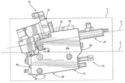
本明細書において、吐出モジュール16a〜16fと、ポンプアセンブリ20a〜20gとを備え、ポンプアセンブリ20gが専用の再循環ポンプアセンブリである、アプリケーター10が記載される。アプリケーター10はまた、制御装置100と、再循環ポンプアセンブリ20gと通信するヒューマンマシンインタラクション(「HMI」)デバイス108とを備え、制御装置100は、再循環ポンプアセンブリ20gの動作を動的に制御するように構成される。制御装置はまた、制御装置のプロセッサによって実行される場合、再循環ポンプアセンブリ20gの動作を動的に制御するプログラムを記憶することができる、メモリ104を備える。
Described herein is an
或る特定の用語が、アプリケーター10を説明するために以下の説明において使用されているが、これは単に便宜上のものであり、限定するものではない。「右」、「左」、「下側」及び「上側」という語は、参照される図面における方向を指している。「内側」及び「外側」という語は、アプリケーター10及びその関連する部品を表す描写の幾何科学的中心に向かう方向及びこの幾何科学的中心から離れる方向をそれぞれ指している。「前方」及び「後方」という語は、アプリケーター10及びその関連する部品に沿った、長手方向2における方向及び長手方向2の反対方向における方向を指している。用語は、上記で列挙された語、その派生語及び類義語を含む。
Certain terms are used in the following description to describe the
本明細書において別途規定されていない限り、「長手」、「鉛直」及び「横」の語は、長手方向2、横方向4及び鉛直方向6によって示される、アプリケーター10の種々の構成要素の直交する方向成分を述べるために使用されている。長手方向2及び横方向4は、水平面に沿って延在するように示され、鉛直方向6は、鉛直面に沿って延在するように示されているが、様々な方向を包含するこれらの平面は、使用時には異なる場合があることを理解されたい。
Unless otherwise specified herein, the terms "longitudinal," "vertical," and "horizontal" are orthogonal to the various components of the
本発明の実施形態は、製品の製造時に接着剤を基材に吐出するアプリケーター10を含む。図1〜図5を参照すると、アプリケーター10は、マニホールド12を備える。アプリケーター10は、頂面32と、鉛直方向6に沿って頂面32の反対側にある底面30と、第1の側面34aと、横方向4に沿って第1の側面34aの反対側にある第2の側面34bと、前面36と、長手方向2に沿って前面36の反対側にある後面38とを有する。第1の側面34a及び第2の側面34bは、前面36から後面38まで延在するとともに、底面30から頂面32まで延在する。マニホールド12は、第1の端部プレート24と、第2の端部プレート26と、第1の端部プレート24及び第2の端部プレート26の間に配置される少なくとも1つのマニホールドセグメント22とによって画定される。結果として、第1の端部プレート24と第2の端部プレート26とは、横方向4に沿って離隔されている。第1の端部プレート24及び第2の端部プレート26と、マニホールドセグメント22とは、動作条件の要求に応じて、マニホールドセグメント22を追加する又はアプリケーター10から除去することができるように、解除可能に接続することができる。結果として、図1〜図5が、3つのマニホールドセグメント22a〜22cを含むものとしてアプリケーター10を示しているが、アプリケーター10は、所望であれば、より多くの又は少ないマニホールドセグメント22を備えることができる。しかしながら、別の実施形態において、マニホールド12は、一体的なマニホールドとすることができる。
An embodiment of the present invention includes an
図2〜図4を参照すると、マニホールド12の第1の側面34aは、第1の平面P1内に位置し、第2の側面34bは、第2の平面P2内に位置する。第2の平面P2は、第1の平面P1に対して平行とすることができる。しかしながら、第1の側面34aと第2の側面34bとが互いに対して角度をなしている場合、第1の平面P1と第2の平面P2とは、平行でなくてもよい。アプリケーター10は、水平面Xを規定し、横方向4及び長手方向2が水平面X内に位置するようになっている。ポンプアセンブリ20は、平面Y内に位置する駆動シャフト軸Aを画定することができる。これらの平面と軸との相互関係は、以下で更に記載される。
With reference to FIGS. 2 to 4, the
アプリケーター10は、入力コネクタ14を備え、この入力コネクタ14を通して、接着剤がマニホールド12内に圧送される。マニホールド12は、ユーザーが接着剤によってマニホールド内に生じる圧力を減衰させることを可能にする圧力解放バルブ17と、接着剤を基材に塗布する吐出モジュール16とを更に備えることができる。圧力解放バルブ17が開かれると、接着剤は、マニホールドからドレーン(図示せず)を通して排出することができる。アプリケーター10は、マニホールド12に取外し可能に取り付けられるポンプアセンブリ20も備える。ポンプアセンブリ20は、接着剤を圧送してマニホールド12の内部チャネルから吐出モジュール16まで流し、次に、吐出モジュール16は、接着剤をノズル21に通してアプリケーターから吐出する。アプリケーター10は、熱素子23を備えることができ、熱素子23は、マニホールド12の温度を上昇させ、それにより、更に、各ポンプアセンブリ20におけるポンプの温度を上昇させるように構成されている。図1〜図5は、アプリケーター10を、5つの熱素子23a〜23eを備えるものとして示しているが、必要に応じて、任意の数の熱素子23を備えることができる。
The
種々の実施形態において、アプリケーター10は、複数のセットのポンプアセンブリ20、吐出モジュール16及びノズル21を備える。図1〜図5に示されているように、例えば、アプリケーター10は、7つのポンプアセンブリ20a、20b、20c、20d、20e、20f及び20gを備えるものとして示されている。図1〜図5は、7つのポンプアセンブリ20a〜20gを示しているが、アプリケーター10は、所望のような任意の数のポンプアセンブリ20を備えることができる。例えば、アプリケーター10は、2つのポンプアセンブリ、3つのポンプアセンブリ、又は4つ以上のポンプアセンブリを備えることができる。ポンプアセンブリ20a〜20gは、アプリケーター10の処理幅を増大させるように並んだ構成に配置することもできる。明確のために、単一のポンプアセンブリ20が以下に記載されている。しかしながら、参照符号20は、参照符号20a〜20gと交換可能に使用することができる。ポンプアセンブリ20a〜20gは、同様のサイズであるものとして示されているが、アプリケーター10に含まれる個々のポンプアセンブリ20のそれぞれは、特定の目的に適合するために、所望のように個別にサイズ決めすることができる。例えば、以下に更に記載される再循環ポンプアセンブリ20gは、他のポンプアセンブリ20a〜20fよりも大きい場合がある。
In various embodiments, the
更に、アプリケーター10は、6つの吐出モジュール16a、16b、16c、16d、16e及び16fを備えるものとして示されている。図1〜図3は、6つの吐出モジュール16a〜16fを示しているが、アプリケーター10は、所望のような任意の数の吐出モジュール16を備えることができる。例えば、アプリケーター10は、1つの吐出モジュール、2つの吐出モジュール、又は3つ以上の吐出モジュールを備えることができる。同様に、単一の吐出モジュール16が以下に記載される。しかしながら、参照符号16は、参照符号16a〜16fと交換可能に使用することができる。また、アプリケーター10は、6つのノズル21a、21b、21c、21d、21e、及び21fを備えるものとして示されている。ノズル21a〜21fのそれぞれは、対応する吐出モジュール16又は吐出モジュール16a〜16fのうちのいくつかの組合せから接着剤供給を受けることができる。ノズル21a〜21fの構成は、ユーザーが動作条件の必要に応じて変更することができ、これには、更なるノズル21を追加するか、又はアプリケーター10に既に結合されているノズル21a〜21fのうちの任意のものを取り外すことを含むことができる。更に、ノズル21a〜21fは、特定の吐出用途に合うように選ばれた異なるタイプのものとすることができる。例えば、図3に示されているように、ノズル21a、21b、21e、及び21fを1つのタイプのノズルとすることができ、一方、ノズル21c及び21dを異なるタイプのノズルとすることができる。
Further, the
図1〜図5を続けて参照すると、ポンプアセンブリ20a〜20fのそれぞれは、吐出モジュール16a〜16fのうちの対応する1つの吐出モジュールと関連付けることができる。動作時、ポンプアセンブリ20a〜20fのそれぞれは、マニホールド12によって供給される接着剤を、吐出モジュール16a〜16fのうちの対応する1つの吐出モジュールに圧送することができ、それにより、吐出モジュール16a〜16fは、接着剤を、ノズル21a〜21fを通して所与の基材に塗布する。しかしながら、各吐出モジュール16は、単一のポンプアセンブリ20に対応せず、複数のポンプアセンブリ20が、接着剤を単一の吐出モジュール16に圧送するようにしてもよい。更に、ポンプアセンブリ20のそれぞれ及び吐出モジュール16のそれぞれは、それぞれのマニホールドセグメント22と結合及び連係することができる。しかしながら、2つ以上のポンプアセンブリ20及び/又は2つ以上の吐出モジュール16が、単一のマニホールドセグメント22に結合してもよい。
With reference to FIGS. 1 to 5 in succession, each of the
一方、ポンプアセンブリ20gは、特定の吐出モジュール16と連係せず、再循環ポンプアセンブリとして指定される。再循環ポンプアセンブリ20gの機能は、以下に記載されるように、再循環チャネル236を通して接着剤を圧送することを含むことができる。したがって、ポンプアセンブリ20gの入口は、再循環チャネル236と流体連通し、ポンプアセンブリ20gの出口は、供給チャネル200と流体連通する。ポンプアセンブリ20gは、第2の側面34bの最も近くに位置するポンプアセンブリ20として示されているが、再循環ポンプアセンブリ20gは、一連のポンプアセンブリ20a〜20gにわたるいずれの場所に位置してもよい。例えば、再循環ポンプアセンブリ20gは、第1の側面34aに最も近いポンプアセンブリとして位置することも、ポンプアセンブリ20a〜20gの中間の場所に位置することもできる。ポンプアセンブリ20gがアプリケーター10の第1の側面34a又は第2の側面34bに最も近いポンプとして位置する場合、第1の端部プレート24又は第2の端部プレート26のうち、ポンプアセンブリ20gが当接する特定の端部プレートは、ポンプアセンブリ20gの一部を受けるように構成することができる。例えば、図5に示されているように、第2の端部プレート26は、ポンプアセンブリ20gを受けるようなサイズの凹部25を有する。ポンプアセンブリ20gが凹部25に配置されると、ポンプアセンブリ20gは、長手方向2及び鉛直方向6に沿って他のポンプアセンブリ20a〜20fと実質的に一列に並ぶことができる。
On the other hand, the
更に、この実施形態では、ポンプアセンブリ20gは、アプリケーター10の唯一の再循環ポンプアセンブリであるように構成されているが、他の実施形態では、アプリケーター10は、それぞれポンプアセンブリ20gとして同様に構成することができる複数の再循環ポンプアセンブリ(図示せず)を備えることができることが想定される。例えば、各吐出モジュール16は、独自の再循環ポンプアセンブリに対応することができる。代替的には、アプリケーター10は、単一の再循環チャネルを通して接着剤を合同で圧送する複数の再循環ポンプアセンブリを備えることができる。
、他の実施形態において、アプリケーター10は、接着剤を吐出モジュール16に圧送することと、接着剤を再循環チャネルに通して圧送することとの双方の機能を含むポンプアセンブリを備えることができる。そのようなポンプアセンブリは、1つのギア段(gear stack)が接着剤を吐出モジュール16に圧送するように機能しながら、他のギア段が接着剤を再循環チャネルに通して圧送するように機能する、単一の二段式ギアポンプ(dual-gear stack pump)として構成することができる。各ギア段は、1つの駆動ギア及び1つの従動ギアを含むことができ、各ギア段は、共通のポンプ本体内に収容することができる。代替的には、各ギア段は、別個のそれぞれのポンプ本体内に収容することができる。更に、各ギア段は、共通のモーターによって駆動することができ、又は代替的には、別個のそれぞれのモーターによって独立して駆動することができる。
Further, in this embodiment, the
In another embodiment, the
図1〜図5ではマニホールド12に取り付けられるものとして示されているが、再循環ポンプアセンブリ20gは、マニホールド12から離隔していてもよい。この構成では、再循環ポンプアセンブリ20gは、1つ以上のホースによってマニホールド12に接続され、それにより、ポンプアセンブリ20gは、マニホールド12から接着剤を受け取るとともに、接着剤をマニホールド12に圧送することが可能である。例えば、1つのホースが、接着剤を再循環チャネル236から再循環ポンプアセンブリ20gに向けることができ、第2のホースが、接着剤を再循環ポンプアセンブリ20gから供給チャネル200に向けることができる。
Although shown to be attached to the manifold 12 in FIGS. 1-5, the
再び図1を参照すると、再循環ポンプアセンブリ20gは、制御装置100及び/又は制御装置100と通信するHMIデバイス108によって制御することができる。制御装置100は、1つ以上の制御装置を含むことができ、また、1つ以上のプロセッサと称することもできる。制御装置100及び/又はHMIデバイス108は、通信リンク120を通じて再循環ポンプアセンブリ20gと有線通信及び/又は無線通信することができ、通信リンク120を通じて再循環ポンプアセンブリ20gに命令を送信するように構成することができる。制御装置100は、プログラマブルロジックコントローラー(PLC)、マイクロプロセッサに基づく制御装置、パーソナルコンピューター、又は、当業者には理解されるような本明細書に記載の機能を実行することが可能な別の従来の制御デバイスとすることができる。例えば、制御装置100は、以下に詳細に記載されるように、ユーザー入力に基づいて再循環ポンプアセンブリ20gを制御することに関連する種々の方法を実行することができる。更に、制御装置100は、制御装置100のメモリユニット104に記憶された動作サイクル又は動作シーケンスのライブラリに基づいて再循環ポンプアセンブリ20gを制御することに関連する種々の方法を実行することができる。メモリユニット104は、1つ以上のメモリユニットを含むことができ、また、記憶デバイスと称することもできる。動作シーケンスは呼び出されると、特定の制御プログラム内に配置され、所望に応じて、制御装置100上で実行される。動作シーケンスは、例えば、HMIデバイス108を通して、異なる吐出動作、異なる基材のタイプ、又は異なる材料のタイプに適応するように調整することができる。
With reference to FIG. 1 again, the
HMIデバイス108は、既知の方法で制御装置100に動作接続される。HMIデバイス108は、操作員が制御装置100の動作を制御し、それにより再循環ポンプアセンブリ20gの動作を制御するのに用いる、キーパッド、押しボタン、制御ノブ、タッチスクリーン等の入力デバイス及び制御部と、ディスプレイ及び他の視覚的なインジケーター等の出力デバイスとを含むことができる。HMIデバイス108は、操作員に可聴アラートを伝えることができるスピーカー等のオーディオ出力デバイスを更に含むことができる。HMIデバイス108を用いることで、操作員は、最大流量、製品あたりのパターン長さ、1分あたりのパターン数、ライン速度、基材のタイプ、基材の識別子、基材の説明、材料のタイプ、基材とアプリケーター10との間の距離等のパラメーターを入力することができる。更に、制御装置100及び/又はHMIデバイス108は、外部ネットワーク(図示せず)と有線通信及び/又は無線通信することができ、それにより、操作員は、別個のシステム又はデバイスから遠隔で制御装置100にアクセスすることができる。
The
引き続き図3及び図4を参照すると、各ポンプアセンブリ20は、複数の異なる構成でマニホールド12に取り付けることができる。1つの実施形態において、各ポンプアセンブリ20は、入口及び出口を有するポンプの底面が、第1の側面34a及び第2の側面34bから離隔されているとともに第1の側面34aと第2の側面34bとの間に位置する場所において、マニホールド12に対面するように、マニホールド12に取り付けられる。この構成では、駆動モーター軸Aは、アプリケーター10の第1の側面34a又は第2の側面34bのいずれとも交差しない。むしろ、ポンプアセンブリ20は、駆動モーター軸Aが、上述したように、第1の側面34aが位置する第1の平面P1に対して平行な平面Y内に位置することができるように、マニホールド12に配置される。平面Yは、第2の側面34bが位置する第2の平面P2に対しても平行とすることができる。各ポンプアセンブリ20a〜20gは、第1の平面P1及び/又は第2の平面P2に対して平行とすることができるそれぞれの平面内に位置するそれぞれの軸Aを有する。更に、マニホールド12に取り付けられる場合、ポンプアセンブリ20a〜20fは、ポンプアセンブリ20a〜20fのそれぞれの入口が鉛直方向6に沿って出口の上に位置するように配置することができる。しかしながら、再循環ポンプアセンブリ20gは、出口が鉛直方向6に沿って入口の上に位置するように、マニホールド12に取り付けてもよい。
Continuing with reference to FIGS. 3 and 4, each
各ポンプアセンブリ20は、駆動モーター軸Aが、平面Y内で任意の特定の方向に向くように、マニホールド12に配置される。例えば、ポンプアセンブリ20は、駆動モーター軸Aが、平面Y内に位置するとともに平面Xに対して角度的にオフセットされるように、マニホールド12に配置することができる。例えば、ポンプアセンブリ20は、駆動モーター軸Aが平面Xに対して或る角度θを規定するように、マニホールド12に配置することができる。角度θは、所望のような任意の角度とすることができる。1つの実施形態において、角度θは、鋭角である。代替的には、角度θは、鈍角、180度よりも大きな角度、又は実質的に90度とすることができる。
Each
図3を参照すると、ポンプアセンブリ20a〜20gのそれぞれは、マニホールド12に取外し可能に取り付けられる。1つの実施形態において、各ポンプアセンブリ20は、締結具27を介してプレート28に固定される。プレート28は、一端部において、締結具29を介して第1の端部プレート24に取り付けられ、反対側の端部において、別の締結具29を介して第2の端部プレート26に取り付けられる。また、締結具29は、プレート28をマニホールドセグメント22のうちの1つに取り付けることができる。締結具27は、ねじ切り加工することができ、ポンプアセンブリ20をマニホールド12から取り外すことには、締結具27をポンプアセンブリ20から緩めて外し、ポンプアセンブリ20をマニホールド12から取り外すことが必要とされる。しかしながら、スロット及び溝システム、スナップフィット係合等のような、ポンプアセンブリ20をマニホールド12に解除可能に取り付ける他の方法が想定される。ポンプアセンブリ20は、上記のようにマニホールド12に解除可能に結合することができるので、特定のポンプアセンブリ20は、アプリケーター10全体を完全に分解することなく、個別に交換することができる。ポンプアセンブリ20は、清掃、損傷、又は接着剤の圧送条件若しくは要件の変化を含む様々な理由で、交換を必要とし得る。
With reference to FIG. 3, each of the
引き続き図6及び図7を参照すると、アプリケーター10を通る接着剤の流路が記載される。任意の特定の要素を通る接着剤の流れが、関連の図に示されている実線の矢印で表されている。アプリケーター10は、入力コネクタ14(図5)に取り付けられるホース(図示せず)を介して接着剤供給部(図示せず)に取り付けることができる。接着剤供給部は、接着剤をアプリケーター10に供給することが可能な任意のデバイスとすることができる。例えば、接着剤供給部は、ホットメルト接着剤をアプリケーター10に供給するように構成された溶融装置とすることができる。接着剤は、接着剤供給部からホースを通り、入力コネクタ14を通って、アプリケーター10のマニホールド12によって画定される供給チャネル200内に流れる。供給チャネル200は、第1の側面34aからマニホールドセグメント22a〜22cのそれぞれを通って第2の側面34bまで延在することができる。しかしながら、供給チャネル200は、必ずしも第1の側面34aから第2の側面34bまで完全に延在しなくてもよく、第1の側面34aと第2の側面34bとの間の内部位置において終端してもよい。更に、供給チャネル200は、所望に応じて、マニホールド12の他の面の組合せの間に延在することができる。
Continuing with reference to FIGS. 6 and 7, the flow path of the adhesive through the
マニホールド12は、供給チャネル200と流体連通する圧力解放チャネル(図示せず)における流れを調節する圧力解放バルブ17を備える。圧力解放バルブ17は、マニホールド12の前面36に位置するものとして示されているが、圧力解放バルブは、所望に応じて、マニホールド12の任意の面に位置することができる。圧力解放バルブ17は、開位置と閉位置との間で切り替えることが可能である。操作員が供給チャネル200内の接着剤の圧力の解放を望む場合、圧力解放バルブ17を閉位置から開位置に切り替える。開位置では、接着剤は、供給チャネル200から圧力解放チャネルを通り、アプリケーター10から出てドレーン(図示せず)を通って流れる。圧力の解放は、操作員がアプリケーター10の点検又はメンテナンス作業を開始しようとするときに所望される場合がある。
The manifold 12 includes a
供給チャネル200がマニホールド12を貫通する場合、指定された再循環ポンプアセンブリ20gを除いてポンプアセンブリ20a〜20fのそれぞれに接着剤が供給される。簡略化のために、図6及び図7に示されているアプリケーター10の断面は、1つのポンプアセンブリ20及び1つの吐出モジュール16に対する接着剤の供給のみを示している。しかしながら、供給チャネル200は、更なるポンプアセンブリ20及び吐出モジュール16のそれぞれにも同様に供給することができる。マニホールドセグメント22は、供給チャネル200からダイバータープレート208まで延在する第1のセグメント入力チャネル204を画定する。ダイバータープレート208は、アプリケーター10においてポンプアセンブリ20とマニホールドセグメント22bとの間に位置することができる。ダイバータープレート208は、アプリケーター10に取外し可能に結合することができ、マニホールド12からポンプアセンブリ20に、そしてまたマニホールド12に接着剤を搬送する様々な通路を画定することができる。例えば、図6に示されているように、ダイバータープレート208は、第1のセグメント入力チャネル204からポンプアセンブリ20の入口52まで延在するダイバーター入力チャネル212を画定する。ダイバータープレート208は、ポンプアセンブリ20dの出口54から第2のセグメント入力チャネル220まで延在するダイバーター出力チャネル216も画定する。しかしながら、ダイバータープレート208は、図示のものとは異なるチャネル構成を含むことができる。図13に示されているダイバータープレート208は、異なる吐出動作の必要に応じて、接着剤を可変の経路でアプリケーター10に通すのに用いることができる、多くの交換可能なダイバータープレートのうちの1つとして機能することができる。
When the
図6及び図7に示されている実施形態では、接着剤は、供給チャネル200から第1のセグメント入力チャネル204を通り、ダイバーター入力チャネル212を通ってポンプアセンブリ20の入口52へと流れる。次いで、ポンプアセンブリ20は、接着剤を出口54から所定の体積流量で圧送する。この所定の体積流量は、ポンプアセンブリ20の入口52に入る際の接着剤の体積流量とは異なることができる。接着剤はそこから、ダイバーター出力チャネル216を通り、第2のセグメント入力チャネル220を通って、吐出流路224へと流れる。吐出流路224は、マニホールドセグメント22に収容されている、吐出モジュール16の下側部分18bによって画定される。吐出流路224は、上側セクション224aと、上側セクション224aの反対側の下側セクション224cと、上側セクション224aと下側セクション224cとの間に配置された中央セクション224bとを画定する。吐出流路224の下側セクション224cは、吐出流路224から離れる側に延在するノズルチャネル228と流体連通する。吐出流路224の上側セクション224aは、吐出流路224の上側セクション224aから再循環チャネル236まで延在する再循環供給チャネル232と流体連通する。再循環チャネル236については、以下で更に論じる。
In the embodiments shown in FIGS. 6 and 7, the adhesive flows from the
吐出モジュール16の下側部分18bは、アプリケーター10のうち、接着剤と直接相互作用してアプリケーター10から出る接着剤の流れを制御する部分である。アプリケーター10は、吐出モジュール16の下側部分18bの反対側にある吐出モジュール16の上側部分18aから、吐出モジュール16の下側部分18bまで延在するバルブステム260を備えることができる。バルブステム260は、下側バルブ部材264及び上側バルブ部材272を画定することができ、上側バルブ部材272は、バルブステム260に沿って下側バルブ部材264から離隔している。吐出モジュール16の下側部分18bは、バルブステム260の下側バルブ部材264と相互作用するように構成された下側バルブシート268と、下側バルブシート268から離隔された上側バルブシート276とを画定することができ、上側バルブシート276は、バルブステム260の上側バルブ部材272と相互作用するように構成される。
The
動作時、バルブステム260は、第1の位置と第2の位置との間で切り替えることができる。バルブステム260が第1の位置にあるとき、吐出モジュール16は、開放形態にある。バルブステム260が第2の位置にあるとき、吐出モジュール16は、閉鎖形態にある。上側バルブ部材272及び下側バルブ部材264は、実質的に反対方向に面することができ、そのため、上側バルブ部材272及び下側バルブ部材264のそれぞれは、第1の位置及び第2の位置のそれぞれにおいて対応する上側バルブシート276及び下側バルブシート268と相互作用する。図6及び図7では、上側バルブ部材272は、吐出モジュール16の上側部分18aに面しないように示されており、一方、下側バルブ部材264は、吐出モジュール16の上側部分18aに面するように示されている。しかしながら、別の実施形態において、この関係は逆であってもよく、それにより、上側バルブ部材272が吐出モジュール16の上側部分18aに面し、下側バルブ部材264は吐出モジュール16の上側部分18aに面しない。1つの実施形態において、第1の位置では、バルブステム260が吐出流路224内で下降され、それにより、バルブステム260の上側バルブ部材272が上側バルブシート276に係合し、下側バルブ部材264が下側バルブシート268から離隔する。この位置では、上側バルブ部材272と上側バルブシート276との間の係合により、吐出流路224の中央セクション224bから上側セクション224aに接着剤が流れることを阻止する。一方、下側バルブ部材264と下側バルブシート268との間の係合がないと、接着剤が吐出流路224の中央セクション224bから下側セクション224cに流れることが可能になる。したがって、バルブステム260が第1の位置にある場合、接着剤は、第2のセグメント入力チャネル220から吐出流路224の中央セクション224b及び下側セクション224cを通ってノズルチャネル228へと流れる。次に、ノズルチャネル228から、接着剤がノズル21を通ってアプリケーター10から出るように流れる。したがって、この実施形態の第1の位置は、製造作業中にアプリケーター10が接着剤を基材に塗布する位置である。
During operation, the
第2の位置では、バルブステム260が吐出流路224内で上昇され、それにより、バルブステム260の上側バルブ部材272が上側バルブシート276から離隔し、下側バルブ部材264が下側バルブシート268に係合する。この位置では、下側バルブ部材264と下側バルブシート268との間の係合により、接着剤が吐出流路224の中央セクション224bから下側セクション224cに流れることを阻止する。一方、上側バルブ部材272と上側バルブシート276との間の係合がないと、接着剤が吐出流路224の中央セクション224bから上側セクション224aに流れることが可能になる。したがって、第2の位置では、接着剤は、第2のセグメント入力チャネル220から吐出流路224の中央セクション224b及び上側セクション224aを通って再循環供給チャネル232へと流れる。接着剤は、再循環供給チャネル232から再循環チャネル236内に流れる。1つの吐出モジュール16及びマニホールドセグメント22が図6及び図7の断面に示されているが、更なる吐出モジュール16及びマニホールドセグメント22のそれぞれを同様に構成することもできる。更に、各吐出モジュール16のバルブステム260は、第1の位置と第2の位置との間で、他のバルブステム260のいずれとも独立して作動するように構成することができ、それにより、任意の時点で、吐出モジュール16のバルブステム260を第1の位置と第2の位置との任意の組合せにすることができる。代替的には、バルブステム260の任意の組合せを、第1の位置と第2の位置との間で一緒に移行するように構成することができる。
In the second position, the
上述した特定の第1の位置と第2の位置との間でバルブステム260を切り替える能力は、いくつかの目的を果たす。1つの目的として、接着剤の吐出動作中、接着剤の一貫した流れが必要又は所望とされない場合があり、したがって、アプリケーター10の操作員は、基材への接着剤の流れの提供及び阻止の双方のために吐出モジュール16を選択的に作動させることが可能でなければならない。バルブステム260を第1の位置から第2の位置に移行させると、接着剤がアプリケーター10を出ることが阻止され、一方、バルブステム260を第2の位置から第1の位置に移行させると、接着剤がアプリケーター10を出ることが可能になる。上述した代替的なバルブステム260の別の目的は、接着剤の流路内の圧力に関する。バルブステム260が第1の位置にあるとき、接着剤は、下側バルブ部材264と下側バルブシート268との間のギャップを通って流れ、ノズル21を通ってアプリケーター10を出ることが可能である。一方、バルブステム260が第2の位置にあるとき、接着剤は、このギャップを通って流れることができない。したがって、使用されない接着剤が吐出流路224及び/又は第2のセグメント入力チャネル220内で停滞する可能性が存在する。この停滞は、アプリケーター10内における圧力の上昇を引き起こす場合がある。この圧力は、バルブステム260の第2の位置から第1の位置への次回の移行時に、基材上の接着剤のハンマーヘッド(hammerhead)等のパターン変形を引き起こす可能性がある。
The ability to switch the
再循環チャネル236がアプリケーター10内に含まれることは、この問題を軽減するのに役立つ。バルブステム260が第2の位置にあるとき、接着剤が吐出流路224の中央セクション224bから上側セクション224aに流れ、再循環供給チャネル232を通って再循環チャネル236へと流れる能力は、接着剤に吐出流路224から脱出する能力を与える。これにより、バルブステム260が第2の位置にあるときに生じ得る圧力の上昇を軽減し、したがって、バルブステム260が第1の位置にあるときにノズル21を通る接着剤の流れを平準化することに役立つことができる。しかしながら、再循環チャネル236を追加するだけでは、この問題を完全に是正することはできない。再循環チャネル236を通って流れる接着剤は、本来、再循環チャネル236内にいくらかの圧力をもたらす。再循環チャネル236が、ポンプアセンブリ20の入口52に、又は接着剤をアプリケーター10に供給する供給タンクに接着剤を戻すように方向付ける形態において、バルブステム260が第2の位置にあるときに、再循環チャネル236を通って流れる接着剤の圧力と供給チャネル200を通って流れる接着剤の圧力との間には差が存在し得る。この圧力差は、再循環チャネル236がない場合にバルブステム260が第2の位置にあるときに存在し得る差と同様に、バルブステム260が第1の位置にあるときのアプリケーター10からの接着剤の流量に負の影響を及ぼす場合がある。特に、この差は、ノズル21を通って流れる接着剤の流量が一貫しないことを引き起こす場合がある。
The inclusion of the
図8は、再循環チャネル236を通る接着剤の流れを管理するシステムを示すプロセスフロー図を示している。実線矢印は、アプリケーター10を通る接着剤の流れを示し、破線矢印は、情報の転送を示している。接着剤は、接着剤供給部(図示せず)から、アプリケーター10の入力コネクタ14(図1)に結合されるホース(図示せず)を通って、供給チャネル200内に流れる。接着剤は、供給チャネル200を通って流れる際、第1の圧力で流れる。第1の圧力を検出するために、供給チャネル200内に第1の圧力センサー112を配置することができる。第1の圧力センサー112は、流体の圧力を測定することが可能な、例えば、圧力トランスデューサー等の任意のタイプの圧力センサーとすることができる。第1の圧力センサー112は、供給チャネル200を通ってポンプアセンブリ20に流れる際の接着剤の第1の圧力を測定することができる。その後、接着剤は、吐出ポンプ20a〜20fを通って流れ、続いて、吐出ポンプ20a〜20fが、接着剤を吐出モジュール16a〜16fに圧送する。吐出モジュール16a〜16fのバルブステム260が第1の位置にあるとき、接着剤がノズル21から流れ出る。代替的には、バルブステム260が第2の位置にあるとき、接着剤が再循環チャネル236に流れ込む。吐出モジュール16a〜16fのそれぞれから再循環チャネル236に流れ込む接着剤は、再循環ポンプアセンブリ20gに向けられる。接着剤は、再循環チャネル236を通って流れる際、第2の圧力で流れる。第2の圧力を検出するために、再循環チャネル236内に第2の圧力センサー116を配置することができる。第2の圧力センサー116は、第1の圧力センサー112と同様、流体の圧力を測定することが可能な、圧力トランスデューサー等の任意のタイプの圧力センサーとすることができる。第1の圧力及び第2の圧力を測定すると、第1の圧力センサー112及び第2の圧力センサー116は、第1の圧力及び第2の圧力を制御装置100に送信する。制御装置100は、第1の圧力センサー112及び第2の圧力センサー116から受信した圧力情報を用いて、再循環ポンプアセンブリ20gの動作をアクティブに指示することができる。したがって、ポンプアセンブリ20gは、他のポンプアセンブリ20a〜20fとは独立して動作可能である。
FIG. 8 shows a process flow diagram showing a system that controls the flow of adhesive through the
再循環ポンプアセンブリ20gは、再循環チャネル236から供給チャネル200に戻すように接着剤を圧送する機能を果たす。再循環ポンプアセンブリ20gを制御する際、制御装置100は、駆動モーターの速度(RPM)を自動的に調整することによって、再循環ポンプアセンブリ20gが再循環チャネル236を通して接着剤を圧送する際の流量をアクティブに制御することができる。その結果、制御装置100は、再循環チャネル236を通って流れる接着剤の第2の圧力を、供給チャネル200を通って流れる接着剤の第1の圧力と実質的に等しくするのに十分な流量で、接着剤を圧送するように、再循環ポンプアセンブリ20gに指示を与えることができる。特に、制御装置308は、第1の圧力センサー112及び第2の圧力センサー116から受信した第1の圧力及び第2の圧力のいずれか又は双方に応じて、モーター速度の増大、モーター速度の減少、又は同じモーター速度の維持を、再循環ポンプアセンブリ20gに指示することができる。これは、第1の圧力と第2の圧力との間の差を軽減するように機能し、それにより、ノズル21を介して基材に塗布される接着剤の体積出力の連続性を維持するのに役立ち得る。制御装置100は、第1の圧力と第2の圧力とが実質的に等しくなるように、又は第1の圧力と第2の圧力との差が相殺されるように、再循環ポンプアセンブリ20gの動作を自律的に制御することを可能にすることができるが、アプリケーター10の操作員は、必要に応じて、再循環ポンプアセンブリ20gの動作を、HMIデバイス108を通して、又は制御装置100のメモリユニット104に記憶されたプログラムを実行することによって、手動で制御することを可能にすることができる。
The
ここで、図9を参照すると、アプリケーター10から所望の接着剤出力を得るために、再循環ポンプアセンブリ20gの動作速度をアクティブに制御する方法300が示されている。まず、ステップ302において、アプリケーター10の操作員は、実行される特定の接着剤吐出動作に関連するプロセス依存特性を、HMIデバイス108を通して制御装置100に入力する。いくつかの実施形態において、プロセス依存特性は、事前に保存された特性を記憶しているメモリから受信することができるか、又はリモートサーバー等の遠隔地から受信することができる。そのような特性は、ポンプアセンブリ20a〜20fのそれぞれの最大ポンプ速度、再循環ポンプアセンブリ20gの最大ポンプ速度、接着剤塗布動作の瞬間ライン速度、接着剤塗布動作の最大ライン速度、製品あたりのパターン長さ、及び1分あたりのパターン数を含むことができる。これらの特性のそれぞれは、実行される特定の接着剤吐出動作、吐出する接着剤のタイプ、又は接着剤が吐出される基材に応じて変化し得る。各ポンプアセンブリ20a〜20fの最大ポンプ速度は、毎分回転数(RPM)の単位によって定義することができる。この単位は、以下で方法300の残りの部分を記載する中で用いられる。しかしながら、ステップ302において、操作員は、グラム毎分(g/分)又は立方センチメートル毎分(cc/分)の単位を用いて、最大ポンプ速度の代わりに各ポンプアセンブリ20a〜20fの最大流量をHMIデバイス108に入力することができることが想定される。その結果、以下に記載する計算は、相応して変化する。
Here, with reference to FIG. 9, a
瞬間ライン速度は、接着剤が塗布される製品又は基材の量に関する接着剤吐出動作の測定速度である。瞬間ライン速度は、1分あたりに接着剤が塗布される製品数(製品/分)、又は代替的には、1分あたりに接着剤が製品に塗布される(メートル単位での)距離(m/分)の単位によって定義することができる。最大ライン速度は、特定の接着剤吐出動作のためにアプリケーター10を用いて接着剤を製品に塗布することができる最大速度であり、瞬間ライン速度と同じ単位で測定される。製品あたりのパターン長さは、吐出モジュール16が個々の製品に対して開放形態にある時間であり、秒(s)単位で測定される。具体的には、パターン長さは、接着剤がノズル21を通って製品上に流れるように吐出モジュール16が閉鎖形態から開放形態に移行したときから、接着剤がノズル21を通ってこれ以上流れないように吐出モジュール16が開放形態から閉鎖形態に移行するときまでの時間である。1分あたりのパターン長さは、1分間に行われるこれらの吐出ステップの総数(パターン/分)である。
The instantaneous line speed is the measured speed of the adhesive ejection operation with respect to the amount of product or substrate to which the adhesive is applied. The instantaneous line speed is the number of products (products / minute) to which the adhesive is applied per minute, or, alternative, the distance (m) at which the adhesive is applied to the products per minute (in meters). It can be defined by the unit of / minute). The maximum line speed is the maximum speed at which the adhesive can be applied to the product using the
プロセス依存特性は、接着剤吐出動作に関連する数値を含むことができ、又は代替的には、接着剤吐出動作の様々な数値的でない記述的特性を含むことができる。そのような記述的特性は、接着剤が塗布される製品のタイプ、特定の製品タイプの傾き(skew)、及び塗布する接着剤のタイプを含むことができる。そのような記述的特性を受信すると、制御装置100は、メモリユニット104にアクセスして、その記述的特性が参照しているそれぞれの接着剤吐出動作に対応する数値特性(最大ポンプ速度、瞬間ライン速度、最大ライン速度、パターン長さ、1分あたりのパターン数等)を得る。その結果、アプリケーター10の操作員は、メモリユニット104が可能性のある各接着剤吐出動作の数値特性を含むように、制御装置100を予めプログラミングすることができる。これにより、操作員がアプリケーター10を制御するのに伴う簡略性を増すことができる。
The process-dependent properties can include numerical values associated with the adhesive ejection operation, or can optionally include various non-numerical descriptive properties of the adhesive ejection operation. Such descriptive properties can include the type of product to which the adhesive is applied, the skew of a particular product type, and the type of adhesive to be applied. Upon receiving such descriptive characteristics, the
引き続き図9を参照すると、ステップ306において、制御装置100は、総平均再循環流量を求める。この値は、或る時間にわたる総計での、ポンプ20a〜20fのそれぞれから再循環チャネル236に流れる接着剤の平均の総体積流量を表し、立方センチメートル毎分(cc/分)の単位で測定される。この計算は、以下に示される式1を用いて行うことができる。

TFRavg=総平均再循環流量(cc/分)、
n=接着剤を吐出モジュールに圧送するポンプの総数、
MPSi=ポンプiの最大ポンプ速度(回転/分)、
LSR=ライン速度率(%)、
VOi=ポンプiの体積出力(cc/回転)、
MOTi=ポンプiに対する吐出モジュールのオン時間比(%)である。
この式において、平均再循環流量は、各ポンプアセンブリの最大ポンプ速度MPSiと、ライン速度率LSRと、各ポンプアセンブリの体積出力VOiと、1から各ポンプアセンブリに対する吐出モジュールのオン時間比MOTiを引いた数とを乗算することで、n個のポンプアセンブリ20のそれぞれについて計算される。次に、n個のポンプアセンブリ20の全てについての平均再循環流量が合計され、これにより、総平均再循環流量TFRavgが得られる。上述したように、ポンプアセンブリ20のそれぞれについての最大ポンプ速度MPSiは、操作員がHMIデバイス108に入力することができ、又は、吐出動作のタイプ等の特性を入力すると、制御装置100によってメモリユニット104から索出することができる。実行される特定の接着剤吐出動作についてのライン速度率LSRは、上述したように、いずれもユーザー入力変数とすることができる、瞬間ライン速度を最大ライン速度で除算することで計算されるか、又は、特定の特性を入力すると、制御装置100によってメモリユニット104から索出することができる。体積出力VOiは、ポンプアセンブリ20a〜20fのそれぞれに可能な接着剤の最大体積出力であり、立方センチメートル毎分(cc/分)で測定される。代替的には、体積出力VOiは、立方センチメートル毎回転(cc/回転)で測定することができる。体積出力VOiは、各ポンプアセンブリ20について既知の値であり、この値は、接着剤吐出動作の開始前に、制御装置100のメモリユニット104内に予めプログラミングすることができる。反対に、体積出力VOiは、アプリケーター10の操作員によっていつでも変更することができるユーザー定義変数とすることもできる。1つの実施形態において、ポンプアセンブリ20a〜20fは、体積出力VOiが0.3cc/分となるようなサイズである。しかしながら、アプリケーター10は、異なる最大体積出力を有する様々なサイズのポンプアセンブリを収容することができることが想定される。
Continuing with reference to FIG. 9, in
TFR avg = total average recirculation flow rate (cc / min),
n = total number of pumps pumping the adhesive to the discharge module,
MPS i = maximum pump speed (rotation / minute) of pump i,
LSR = line speed rate (%),
VO i = pump i volume output (cc / rotation),
MOT i = on-time ratio (%) of the discharge module to the pump i.
In this equation, the average recirculation flow rate is the maximum pump speed MPS i of each pump assembly, the line speed factor LSR, the volume output VO i of each pump assembly, and the on-time ratio MOT of the discharge module from 1 to each pump assembly. Calculated for each of the
吐出モジュールのオン時間比MOTiは、特定のポンプアセンブリ20に対応する吐出モジュール16が開放形態にある時間のパーセンテージである。これは、単一の吐出パターンに対する秒単位でのモジュールのオン時間と、1分間に吐出モジュール16によって吐出されるパターン数とを乗算し、その数を60秒で除算することによって計算される。式1に示されているように、1から吐出モジュールのオン時間比MOTiを減算することにより、有効な結果は、吐出モジュール16が閉鎖形態にある、すなわち、接着剤が再循環チャネル236に向けられる時間の比となる。その結果、吐出オン時間比MOTiは、吐出モジュール16が閉鎖形態にある時間の比に対する補数となる。吐出モジュールのオン時間比MOTiは、操作員が選んだプロセス依存特性から制御装置100により求めることができるか、又は、操作員がHMIデバイス108に直接入力することができる。
The discharge module on-time ratio MOT i is the percentage of time that the
ステップ306において総平均再循環流量を求めた後、ステップ308において、制御装置100は、接着剤を再循環チャネル236から供給チャネル200に圧送するのに必要な再循環ポンプ速度を求める。式2(下記)において計算された必要な再循環ポンプ速度は、吐出モジュール16から吐出される接着剤の所望の圧力に悪影響を及ぼすことなく、再循環される接着剤をポンプアセンブリ20a〜20fから供給チャネル200に圧送するために、再循環ポンプアセンブリ20gが動作しなければならない速度を表す。式2に従って行われる計算を以下に示す。
RPS=必要な再循環ポンプ速度(回転/分)、
TFRavg=総平均再循環流量(cc/分)、
RVO=再循環ポンプの体積出力(cc/回転)である。
この式において、必要な再循環ポンプ速度RPSは、総平均再循環流量TFRavgを再循環ポンプの体積出力RVOで除算することによって計算される。上述したように、総平均再循環流量TFRavgは、式1を用いて求めることができる。再循環ポンプの体積出力RVOは、再循環ポンプアセンブリ20gが可能な最大体積出力であり、立方センチメートル毎回転(cc/回転)で測定される。1つの実施形態において、再循環ポンプアセンブリ20gは、4.0cc/回転という再循環ポンプの体積出力を有する。しかしながら、再循環ポンプアセンブリ20gは、異なるサイズとすることができ、それに応じて、再循環ポンプの体積出力は変化する。再循環ポンプの体積出力RVOは、制御装置のメモリユニット104内に予めプログラミングすることができ、又は代替的には、アプリケーター10の操作員がHMIデバイス108に入力することができる。
After determining the total average recirculation flow rate in
RPS = required recirculation pump speed (rotation / minute),
TFR avg = total average recirculation flow rate (cc / min),
RVO = volume output (cc / rotation) of the recirculation pump.
In this equation, the required recirculation pump speed RPS is calculated by dividing the total average recirculation flow rate TFR avg by the volume output RVO of the recirculation pump. As described above, the total average recirculation flow rate TFR avg can be determined using Equation 1. The volume output RVO of the recirculation pump is the maximum volume output possible for 20 g of the recirculation pump assembly and is measured at cubic centimeter per revolution (cc / revolution). In one embodiment, 20 g of the recirculation pump assembly has a volume output of the recirculation pump of 4.0 cc / revolution. However, the
別の実施形態において、ステップ308は、再循環ポンプアセンブリ20gに必要な再循環モーター速度を求めることを伴う。これは、必要な再循環ポンプ速度RPSと、再循環ポンプアセンブリ20gのギアボックス減速比とを乗算することによって行われる。ギアボックス減速比は、当該技術分野において既知のように、再循環ポンプアセンブリ20gにおけるモーターアセンブリ(図示せず)の駆動ギアとポンプアセンブリ(図示せず)の従動ギアとの間のサイズ比を指す。1つの実施形態において、再循環ポンプアセンブリ20gのギアボックス減速比は、23:1である。しかしながら、再循環ポンプアセンブリ20gの駆動ギア及び従動ギアは、異なる構成とすることができ、それにより、ギアボックス減速比は変化する。
In another embodiment,
引き続き図9を参照すると、ステップ308において必要な再循環ポンプ速度RPSを求めると、制御装置100は、次に、ステップ312において、再循環ポンプアセンブリ20gの動作速度を、必要な再循環ポンプ速度RPSに合致させるように調整することができる。再循環ポンプアセンブリ20gの動作速度を調整するステップは、制御装置100によって自動的に実行することができる。代替的には、HMIデバイスは、必要な再循環ポンプ速度RPSを出力デバイス上に表示することができ、アプリケーター10の操作員が、制御装置100及び/又はデバイス108を用いて、再循環ポンプアセンブリ20gの動作速度を、必要な動作速度に合致させるように、手動で調整することができる。
Continuing with reference to FIG. 9, when the required recirculation pump speed RPS was obtained in
再循環ポンプアセンブリ20gの動作速度を、ステップ308で求めた必要な再循環ポンプ速度RPSに合致させるように調整した後、再循環ポンプアセンブリ20gの動作速度をステップ316において補整することができる。ステップ316において、ポンプ動作速度が必要な再循環ポンプ速度RPSよりも高速又は低速となるように、動作速度を補整することができる。したがって、操作員は、所望に応じて、HMIデバイス108に調整値を入力することによって、再循環ポンプアセンブリ20gの動作速度を手動で増大又は減少させることができる。代替的には、制御装置100は、この補整ステップを、所定のプログラムに従って自動的に実行することができる。この補整ステップは、アプリケーター10の通常動作中に生じる圧力変動を担うように行うことができる。例えば、吐出モジュール16を開放形態と閉鎖形態との間で切り替えるステップ、特に、バルブステム260が吐出流路224内で動く際に生じる結果的な体積変動は、吐出流路224内に圧力変動をもたらすか、又は供給チャネル200と再循環チャネル236との間に圧力差をもたらす可能性がある。これは、吐出モジュール16の中での計量の正確性のばらつき、又は基材上での接着剤パターンの変形をもたらし得る。再循環ポンプ20gの動作速度を必要な再循環ポンプ速度RPSに対して増大又は減少させることにより、アプリケーターの操作員は、これらの問題の影響を軽減することができる。
After adjusting the operating speed of the
特に方法300の実施における再循環ポンプアセンブリ20gの動作を制御するために、制御装置100及びHMIデバイス108を使用することにより、アプリケーター10の全体構成を簡略化することができる。再循環ポンプアセンブリ20gを用いることによって、外部の再循環ホースの使用は必要がなくなる。更に、再循環ポンプアセンブリ20gの動作速度を動的に制御することにより、アプリケーター10内の接着剤の圧力は、アプリケーター10を出る接着剤の制御可能かつ一貫した流量を確実にするように一定的に調節される。これにより、基材上での一貫した接着剤パターン品質が繰り返しもたらされることが確実になる。その結果、ハンマーヘッド等の基材上のパターン変形を回避することができる。
The overall configuration of the
更に、制御装置100及びHMIデバイス108を使用することにより、アプリケーター10の操作員は、再循環ポンプアセンブリ20gの動作を連続的に制御及び変更することが可能である。その結果、操作員は、ポンプアセンブリ20a〜20fにおける変更、再循環ポンプアセンブリ20gにおける変更、接着剤タイプの変更、基材タイプ又は吐出動作の変更等を手動で担うことができる。代替的には、制御装置100が、そのような変更を自動で担うことができる。更に、操作員は、再循環ポンプアセンブリ20gの速度を補整する能力を有し、したがって、所定のモード又は動作によって制約を受けることはない。
Further, by using the
本発明は、限定された数の実施形態を用いて本明細書において記載したが、これらの特定の実施形態は、本願において別途記載されるとともに特許請求されるように本発明の範囲を限定することを意図されたものではない。本明細書に記載されている物品及び方法の様々な要素の正確な構成及びステップの順序は、限定的であるとみなされるべきではない。例えば、方法のステップが、図における順番に連続する参照符号及びブロックの進行を参照しながら記載されていても、その方法は、所望のような特定の順序で実施することができる。 The present invention has been described herein using a limited number of embodiments, but these particular embodiments limit the scope of the invention as described separately and claimed in the present application. It was not intended to be. The exact configuration of the various elements of the articles and methods described herein and the order of the steps should not be considered limiting. For example, the method can be performed in a particular order as desired, even though the steps of the method are described with reference to the sequential reference codes and block progressions in the figure.
Claims (15)
プロセス依存特性を受信することと、
前記プロセス依存特性に基づいて、前記再循環ポンプアセンブリに流れる接着剤の再循環流量を求めることと、
前記接着剤の前記再循環流量に基づいて、前記接着剤を前記再循環ポンプアセンブリとは別の少なくとも1つのポンプアセンブリに供給する供給チャネルに前記接着剤を圧送するように構成された前記再循環ポンプアセンブリの所望の再循環ポンプ速度を求めることと、
前記再循環ポンプアセンブリの動作速度を前記所望の再循環ポンプ速度に合致させるように調整することと、
を含む、方法。 A way to control the recirculation pump assembly
Receiving process-dependent characteristics and
Based on the process-dependent characteristics, and determining the recirculation flow of the adhesive flowing through the recirculation pump assembly,
The recirculation configured to pump the adhesive to a supply channel that supplies the adhesive to at least one pump assembly separate from the recirculation pump assembly based on the recirculation flow rate of the adhesive. Finding the desired recirculation pump speed for the pump assembly and
Adjusting the operating speed of the recirculation pump assembly to match the desired recirculation pump speed.
Including methods.
プロセス依存特性を受信することと、
前記プロセス依存特性に基づいて、前記再循環ポンプアセンブリに流れる接着剤の再循環流量を求めることと、
前記接着剤の前記再循環流量に基づいて、前記接着剤を前記再循環ポンプアセンブリとは別の少なくとも1つのポンプアセンブリに供給する供給チャネルに圧送するように構成された前記再循環ポンプアセンブリの所望の再循環ポンプ速度を求めることと、
前記再循環ポンプアセンブリの動作速度を前記再循環ポンプ速度に合致させるように調整することと、
を行うように構成される、システム。 A system for controlling the recirculation pump assembly, said system comprising: one or more processors, and one or more storage devices communicating with said recirculation pump assembly and electrical, the system comprising:
Receiving process-dependent characteristics and
Based on the process-dependent characteristics, and determining the recirculation flow of the adhesive flowing through the recirculation pump assembly,
Desired for the recirculation pump assembly configured to pump the adhesive to a supply channel that supplies at least one pump assembly separate from the recirculation pump assembly based on the recirculation flow rate of the adhesive. and determining the recirculation pump speed of,
Adjusting the operating speed of the recirculation pump assembly to match the recirculation pump speed,
A system that is configured to do.
Applications Claiming Priority (3)
| Application Number | Priority Date | Filing Date | Title |
|---|---|---|---|
| US201662385238P | 2016-09-08 | 2016-09-08 | |
| US62/385,238 | 2016-09-08 | ||
| PCT/US2017/050417 WO2018048993A1 (en) | 2016-09-08 | 2017-09-07 | System and method for active adhesive recirculation control |
Publications (3)
| Publication Number | Publication Date |
|---|---|
| JP2019529089A JP2019529089A (en) | 2019-10-17 |
| JP2019529089A5 JP2019529089A5 (en) | 2020-10-15 |
| JP6937824B2 true JP6937824B2 (en) | 2021-09-22 |
Family
ID=59895427
Family Applications (5)
| Application Number | Title | Priority Date | Filing Date |
|---|---|---|---|
| JP2019513328A Active JP6935490B2 (en) | 2016-09-08 | 2017-09-07 | Regulation of active adhesive recirculation |
| JP2019513383A Active JP6937824B2 (en) | 2016-09-08 | 2017-09-07 | Systems and methods for active adhesive recirculation control |
| JP2019513409A Active JP7027410B2 (en) | 2016-09-08 | 2017-09-07 | Adhesive ejection system with convertible nozzle assembly |
| JP2019513334A Active JP6921184B2 (en) | 2016-09-08 | 2017-09-07 | Applicator with at least one pump with integrated drive |
| JP2019513408A Active JP6983228B2 (en) | 2016-09-08 | 2017-09-07 | Applicator with divertor plate |
Family Applications Before (1)
| Application Number | Title | Priority Date | Filing Date |
|---|---|---|---|
| JP2019513328A Active JP6935490B2 (en) | 2016-09-08 | 2017-09-07 | Regulation of active adhesive recirculation |
Family Applications After (3)
| Application Number | Title | Priority Date | Filing Date |
|---|---|---|---|
| JP2019513409A Active JP7027410B2 (en) | 2016-09-08 | 2017-09-07 | Adhesive ejection system with convertible nozzle assembly |
| JP2019513334A Active JP6921184B2 (en) | 2016-09-08 | 2017-09-07 | Applicator with at least one pump with integrated drive |
| JP2019513408A Active JP6983228B2 (en) | 2016-09-08 | 2017-09-07 | Applicator with divertor plate |
Country Status (6)
| Country | Link |
|---|---|
| US (10) | US10040092B2 (en) |
| EP (5) | EP3509759B1 (en) |
| JP (5) | JP6935490B2 (en) |
| CN (5) | CN109803769B (en) |
| ES (2) | ES2935579T3 (en) |
| WO (5) | WO2018048993A1 (en) |
Families Citing this family (17)
| Publication number | Priority date | Publication date | Assignee | Title |
|---|---|---|---|---|
| US10695779B2 (en) | 2016-09-08 | 2020-06-30 | Nordson Corporation | Applicator having active backpressure control devices |
| CN109843449B (en) | 2016-09-08 | 2022-02-18 | 诺信公司 | Remote metering station |
| WO2018048993A1 (en) | 2016-09-08 | 2018-03-15 | Nordson Corporation | System and method for active adhesive recirculation control |
| US11174858B2 (en) * | 2018-01-26 | 2021-11-16 | Waterblasting, Llc | Pump for melted thermoplastic materials |
| DE102018118100A1 (en) * | 2018-07-26 | 2020-01-30 | Ebm-Papst St. Georgen Gmbh & Co. Kg | Pump with absolute rotation angle detection |
| EP3877095A2 (en) * | 2018-11-09 | 2021-09-15 | Illinois Tool Works Inc. | Modular fluid application device for varying fluid coat weight |
| CN109664591B (en) * | 2018-12-17 | 2020-08-28 | 重庆鼎盛印务股份有限公司 | PTP aluminum foil printing coating device |
| WO2020210144A1 (en) * | 2019-04-08 | 2020-10-15 | Nordson Corporation | Applicator having active backpressure control devices |
| US11969748B2 (en) * | 2019-06-20 | 2024-04-30 | Nordson Corporation | Liquid dispensing systems with reduced noise levels |
| CN112570201A (en) * | 2019-09-29 | 2021-03-30 | 深圳市向宇龙自动化设备有限公司 | Multi-channel multi-aperture dispensing device |
| CN110665753B (en) * | 2019-11-22 | 2021-07-23 | 东莞方德泡绵制品厂有限公司 | Intermittent adhesive dispensing device for production of automotive interior fittings |
| CN111203365A (en) * | 2020-01-10 | 2020-05-29 | 望汭(上海)自动化技术有限公司 | Double-metering-cylinder operation platform |
| US11701784B2 (en) * | 2020-05-22 | 2023-07-18 | The Boeing Company | Robot end effector for dispensing an extrudable substance |
| CN111617938B (en) * | 2020-06-15 | 2021-05-18 | 诸暨易阳环保科技有限公司 | Automatic painting equipment for semicircular workpieces |
| CN111822243B (en) * | 2020-07-03 | 2021-09-21 | 江苏海濎智能科技有限公司 | Automatic change spreading machine system |
| US11484905B1 (en) * | 2021-04-30 | 2022-11-01 | Nordson Corporation | Spray nozzle clamp |
| CN117943231B (en) * | 2024-03-26 | 2024-05-28 | 广东亚盈铝业有限公司 | Open pore spraying production method and production line |
Family Cites Families (87)
| Publication number | Priority date | Publication date | Assignee | Title |
|---|---|---|---|---|
| GB1119514A (en) * | 1965-10-29 | 1968-07-10 | Stanley Horrocks | Production of solids from solutions or slurries by evaporation |
| US4687137A (en) | 1986-03-20 | 1987-08-18 | Nordson Corporation | Continuous/intermittent adhesive dispensing apparatus |
| US5228594A (en) * | 1990-11-30 | 1993-07-20 | Aeroquip Corporation | Metered liquid dispensing system |
| DE4121792A1 (en) | 1991-07-02 | 1993-01-07 | Kolbus Gmbh & Co Kg | Book back gluing nozzle system - has self adjusting pressure relief discharge at higher than application pressure |
| US5236641A (en) * | 1991-09-11 | 1993-08-17 | Exxon Chemical Patents Inc. | Metering meltblowing system |
| ES2121077T3 (en) * | 1992-02-13 | 1998-11-16 | Accurate Prod Co | HOT BLOW MATRIX WITH AIR PASS AND PRE-ADJUSTABLE SEPARATION. |
| US5265800A (en) * | 1993-01-25 | 1993-11-30 | Nordson Corporation | Adhesive spray gun with adjustable module and method of assembling |
| US5389151A (en) * | 1993-03-15 | 1995-02-14 | Nordson Corporation | Interchangeable contact/non-contact dispensing system |
| DE4310518C1 (en) | 1993-03-31 | 1994-07-28 | Hutter Sandra | Gear pump for pumping a flowable medium |
| US5409642A (en) | 1993-10-06 | 1995-04-25 | Exxon Chemical Patents Inc. | Melt blowing of tubular filters |
| US5458684A (en) | 1994-02-09 | 1995-10-17 | Nordson Corporation | Hot melt adhesive spray apparatus |
| US5458291A (en) | 1994-03-16 | 1995-10-17 | Nordson Corporation | Fluid applicator with a noncontacting die set |
| US5727933A (en) | 1995-12-20 | 1998-03-17 | Hale Fire Pump Company | Pump and flow sensor combination |
| JPH09173917A (en) | 1995-12-21 | 1997-07-08 | Mitsubishi Heavy Ind Ltd | Apparatus for producing hot melt foam |
| US6726465B2 (en) | 1996-03-22 | 2004-04-27 | Rodney J. Groleau | Injection molding machine employing a flow path gear pump and method of use |
| US5862986A (en) | 1996-07-16 | 1999-01-26 | Illinois Tool Works, Inc. | Hot melt adhesive applicator with metering gear-driven head |
| JPH1034056A (en) | 1996-07-23 | 1998-02-10 | Kyushu Plant Kk | Controller for feeding coating material and method therefor |
| US5740963A (en) * | 1997-01-07 | 1998-04-21 | Nordson Corporation | Self-sealing slot nozzle die |
| US6210141B1 (en) | 1998-02-10 | 2001-04-03 | Nordson Corporation | Modular die with quick change die tip or nozzle |
| DE19817274A1 (en) | 1998-04-18 | 1999-10-28 | Cemag Gmbh | Fine grinding process for mineral and non-mineral materials |
| US6422428B1 (en) * | 1998-04-20 | 2002-07-23 | Nordson Corporation | Segmented applicator for hot melt adhesives or other thermoplastic materials |
| US6296463B1 (en) | 1998-04-20 | 2001-10-02 | Nordson Corporation | Segmented metering die for hot melt adhesives or other polymer melts |
| US6089413A (en) | 1998-09-15 | 2000-07-18 | Nordson Corporation | Liquid dispensing and recirculating module |
| US20010024618A1 (en) | 1999-12-01 | 2001-09-27 | Winmill Len F. | Adjustable-displacement gear pump |
| US6517891B1 (en) | 2000-10-31 | 2003-02-11 | Nordson Corporation | Control system for metering pump and method |
| US6499631B2 (en) | 2001-01-26 | 2002-12-31 | Illinois Tool Works Inc. | Hot melt adhesive applicator |
| EP1243342B9 (en) | 2001-03-22 | 2010-02-17 | Nordson Corporation | Universal dispensing system for air assisted extrusion of liquid filaments |
| US20020139818A1 (en) | 2001-03-29 | 2002-10-03 | Mcguffey Grant | Snuffback-diversion flow valve system |
| US6607104B2 (en) | 2001-05-24 | 2003-08-19 | Illinois Tool Works Inc. | Metered output hot melt adhesive dispensing system with return isolation loop |
| US6601741B2 (en) | 2001-11-28 | 2003-08-05 | Illinois Tool Works Inc. | Laminated distribution manifold plate system |
| US6814310B2 (en) | 2002-11-26 | 2004-11-09 | Nordson Corporation | Metered liquid dispensing system |
| US6688498B1 (en) | 2002-12-12 | 2004-02-10 | Illinois Tool Works Inc. | Hot melt adhesive supply system with independent gear pump assemblies |
| US20040159672A1 (en) | 2003-01-31 | 2004-08-19 | Nordson Corporation | Apparatus and methods for recirculating liquid dispensing systems |
| CN2644737Y (en) * | 2003-07-26 | 2004-09-29 | 陈斌 | Multi-purpose booster pump |
| DE202004001480U1 (en) | 2004-01-30 | 2004-04-01 | Nordson Corporation, Westlake | Applicator head for coating moving substrate has a clamp fitting via an adaptor plate fitted to the spray support structure |
| US20050230423A1 (en) | 2004-04-14 | 2005-10-20 | Riney John M | Applicators for liquid hot melt adhesive and methods of applying liquid hot melt adhesive |
| DE202004007024U1 (en) | 2004-04-30 | 2004-07-01 | Nordson Corporation, Westlake | Application head, application nozzle arrangement, adapter plate and mounting plate |
| US20050242108A1 (en) * | 2004-04-30 | 2005-11-03 | Nordson Corporation | Liquid dispenser having individualized process air control |
| KR20060002266A (en) * | 2004-07-01 | 2006-01-09 | 삼성전자주식회사 | Apparatus for manufacturing liquid crystal display |
| US7626143B2 (en) | 2005-02-17 | 2009-12-01 | Scott Richard Miller | Apparatus and method for processing hot melt adhesives |
| EP1937974B1 (en) * | 2005-10-17 | 2012-03-07 | Illinois Tool Works Inc. | Remote hot melt adhesive metering station |
| EP1979144B1 (en) | 2006-01-17 | 2012-01-04 | Nordson Corporation | Apparatus and method for melting and dispensing thermoplastic material |
| US7611071B2 (en) | 2006-04-24 | 2009-11-03 | Illinois Tool Works Inc. | Intermittently operable recirculating control module and dispensing nozzle having internally disposed fixed orifice |
| JP4566955B2 (en) | 2006-07-11 | 2010-10-20 | 株式会社コガネイ | Chemical solution supply apparatus and chemical solution supply method |
| US20080023489A1 (en) | 2006-07-31 | 2008-01-31 | Illinois Tool Works Inc. | Remote metering station and applicator heads interconnected by means of relatively short hoses with universal connectors |
| DE202006016674U1 (en) * | 2006-10-27 | 2007-02-22 | Nordson Corporation, Westlake | Application device for flat application of liquid material, especially hot melt glue, has clamping device for fastening of nozzle arrangement on basic body |
| CN200999361Y (en) | 2007-01-17 | 2008-01-02 | 万凯钧 | Current divider |
| DE102007002980A1 (en) | 2007-01-19 | 2008-07-24 | Voith Patent Gmbh | Adhesive applicator for a paper or cardboard processing machine |
| US7874456B2 (en) | 2007-02-12 | 2011-01-25 | Illinois Tool Works Inc. | Modular system for delivering hot melt adhesive or other thermoplastic materials, and pressure control system therefor |
| US10137472B2 (en) | 2007-04-06 | 2018-11-27 | Illinois Tool Works Inc. | Dual pattern shim assembly for use in conjunction with hot melt adhesive dispensing systems |
| US7908997B2 (en) | 2007-06-04 | 2011-03-22 | Illinois Tool Works Inc. | Hybrid hot melt adhesive or other thermoplastic material dispensing system |
| EP2002898A1 (en) | 2007-06-14 | 2008-12-17 | J. Zimmer Maschinenbau Gesellschaft m.b.H. | Application device for applying a fluid onto a substrate with valve devices, method for cleaning the application device and valve device for application device |
| DE102007030220B4 (en) * | 2007-06-29 | 2013-04-04 | Khs Gmbh | Spray tube and spray station with such a spray tube |
| KR200441757Y1 (en) | 2007-09-21 | 2008-09-05 | 유길수 | Color line marking device for tire |
| US8074902B2 (en) * | 2008-04-14 | 2011-12-13 | Nordson Corporation | Nozzle and method for dispensing random pattern of adhesive filaments |
| US8413848B2 (en) | 2008-04-25 | 2013-04-09 | Illinois Tool Works Inc. | Hot melt adhesive metering system with interchangeable output assemblies |
| US8561656B2 (en) * | 2008-10-31 | 2013-10-22 | Michael Eginton | Adaptable bench top filling system |
| US8445061B2 (en) | 2009-07-17 | 2013-05-21 | Illinois Tool Works Inc. | Metering system for hot melt adhesives with variable adhesive volumes |
| US8551562B2 (en) * | 2009-07-17 | 2013-10-08 | Illnois Tool Works Inc. | Method for metering hot melt adhesives with variable adhesive volumes |
| US9573159B2 (en) | 2009-08-31 | 2017-02-21 | Illinois Tool Works, Inc. | Metering system for simultaneously dispensing two different adhesives from a single metering device or applicator onto a common substrate |
| US9718081B2 (en) | 2009-08-31 | 2017-08-01 | Illinois Tool Works Inc. | Metering system for simultaneously dispensing two different adhesives from a single metering device or applicator onto a common substrate |
| JP5784025B2 (en) | 2009-10-05 | 2015-09-24 | ノードソン コーポレーションNordson Corporation | Two-component liquid discharge gun and system |
| DE102010055019A1 (en) | 2010-12-17 | 2012-06-21 | Illinois Tool Works Inc. | Device for the intermittent application of a liquid to pasty medium on an application surface |
| MX352005B (en) | 2011-04-11 | 2017-11-07 | Nordson Corp | System, nozzle, and method for coating elastic strands. |
| FR2978684B1 (en) * | 2011-08-01 | 2013-08-23 | Valois Sas | HEAD OF DISTRIBUTION AND APPLICATION. |
| DE202011107265U1 (en) | 2011-10-31 | 2013-02-11 | Nordson Corporation | Dispensing module, applicator head and nozzle for dispensing a fluid, in particular hot melt adhesive |
| US8496457B2 (en) | 2011-10-31 | 2013-07-30 | Nordson Corporation | Metering gear pump with integral flow indicator |
| CN202517128U (en) * | 2012-02-29 | 2012-11-07 | 莱芜钢铁集团有限公司 | Multi-direction saw blade cooling and cleaning device |
| CN202725435U (en) * | 2012-06-25 | 2013-02-13 | 上海峰晟机械设备有限公司 | Glass fiber glue injecting volley installation mechanism |
| DE102012216817A1 (en) | 2012-09-19 | 2014-03-20 | Nordson Corporation | Metering device for a fluid |
| US9481008B2 (en) | 2013-07-11 | 2016-11-01 | Toyota Motor Engineering & Manufacturing North America, Inc. | Reclaim sealer application apparatus and method |
| WO2015057729A2 (en) | 2013-10-15 | 2015-04-23 | Corning Incorporated | Systems and methods for skinning articles |
| EP3123029B1 (en) | 2014-03-25 | 2024-03-20 | Project Phoenix, LLC | System to pump fluid and control thereof |
| WO2015187673A1 (en) * | 2014-06-02 | 2015-12-10 | Afshari Thomas | Linear actuator assembly and system |
| US9724722B2 (en) * | 2014-06-10 | 2017-08-08 | Illinois Tool Works Inc. | Rapid changeover slot die assembly for a fluid application device |
| US10539134B2 (en) | 2014-10-06 | 2020-01-21 | Project Phoenix, LLC | Linear actuator assembly and system |
| CN204412579U (en) * | 2015-01-05 | 2015-06-24 | 江苏东光电子有限公司 | A kind of coated board |
| US9415415B1 (en) | 2015-03-06 | 2016-08-16 | Nordson Corporation | Liquid dividing module for variable output dispensing applicator and associated methods |
| US20160256889A1 (en) * | 2015-03-06 | 2016-09-08 | Nordson Corporation | Variable output dispensing applicator and associated methods of dispensing |
| US9925552B2 (en) | 2015-03-09 | 2018-03-27 | Nordson Corporation | Liquid dispensing applicators having backpressure control devices, and related methods |
| US9718085B2 (en) | 2015-04-20 | 2017-08-01 | Illinois Tool Works Inc. | Hot melt adhesive applicator system with small footprint |
| TWI704286B (en) | 2015-09-02 | 2020-09-11 | 美商鳳凰計劃股份有限公司 | System to pump fluid and control thereof |
| WO2017040825A1 (en) | 2015-09-02 | 2017-03-09 | Project Phoenix, LLC | System to pump fluid and control thereof |
| US9889599B2 (en) | 2015-09-15 | 2018-02-13 | Illinois Tool Works Inc. | Multi-temperature contact applicator |
| CN109843449B (en) | 2016-09-08 | 2022-02-18 | 诺信公司 | Remote metering station |
| WO2018048993A1 (en) | 2016-09-08 | 2018-03-15 | Nordson Corporation | System and method for active adhesive recirculation control |
| EP3546071B1 (en) | 2018-03-27 | 2022-01-19 | Robatech AG | Device for intermittently applying a flowable substance and method for applying such a substance |
-
2017
- 2017-09-07 WO PCT/US2017/050417 patent/WO2018048993A1/en active Search and Examination
- 2017-09-07 CN CN201780062635.6A patent/CN109803769B/en active Active
- 2017-09-07 CN CN201780063052.5A patent/CN109843450B/en active Active
- 2017-09-07 US US15/698,216 patent/US10040092B2/en active Active
- 2017-09-07 EP EP17768928.8A patent/EP3509759B1/en active Active
- 2017-09-07 US US15/698,036 patent/US10272464B2/en active Active
- 2017-09-07 CN CN201780052777.4A patent/CN109641233B/en active Active
- 2017-09-07 JP JP2019513328A patent/JP6935490B2/en active Active
- 2017-09-07 JP JP2019513383A patent/JP6937824B2/en active Active
- 2017-09-07 WO PCT/US2017/050368 patent/WO2018048967A1/en unknown
- 2017-09-07 WO PCT/US2017/050406 patent/WO2018048987A2/en unknown
- 2017-09-07 US US15/697,711 patent/US10758934B2/en active Active
- 2017-09-07 EP EP17768919.7A patent/EP3509758A2/en active Pending
- 2017-09-07 ES ES17769159T patent/ES2935579T3/en active Active
- 2017-09-07 JP JP2019513409A patent/JP7027410B2/en active Active
- 2017-09-07 CN CN201780052275.1A patent/CN109641232B/en active Active
- 2017-09-07 ES ES17768928T patent/ES2847950T3/en active Active
- 2017-09-07 US US15/697,981 patent/US10864544B2/en active Active
- 2017-09-07 CN CN201780052041.7A patent/CN109641231A/en active Pending
- 2017-09-07 US US15/698,086 patent/US11148167B2/en active Active
- 2017-09-07 EP EP17768918.9A patent/EP3509757B1/en active Active
- 2017-09-07 JP JP2019513334A patent/JP6921184B2/en active Active
- 2017-09-07 WO PCT/US2017/050373 patent/WO2018048968A1/en unknown
- 2017-09-07 EP EP17768609.4A patent/EP3509756B1/en active Active
- 2017-09-07 EP EP17769159.9A patent/EP3509760B1/en active Active
- 2017-09-07 JP JP2019513408A patent/JP6983228B2/en active Active
- 2017-09-07 WO PCT/US2017/050509 patent/WO2018049048A1/en unknown
-
2018
- 2018-07-26 US US16/045,743 patent/US10610882B2/en active Active
-
2020
- 2020-07-22 US US16/935,402 patent/US11344909B2/en active Active
- 2020-10-09 US US17/066,610 patent/US11607706B2/en active Active
-
2021
- 2021-09-15 US US17/475,776 patent/US11766694B2/en active Active
-
2023
- 2023-03-14 US US18/121,173 patent/US11975350B2/en active Active
Also Published As
Similar Documents
| Publication | Publication Date | Title |
|---|---|---|
| JP6937824B2 (en) | Systems and methods for active adhesive recirculation control | |
| KR102586367B1 (en) | Method and apparatus for surface finishing and removal of support material (DECI DUO) | |
| KR101887737B1 (en) | Pumping system | |
| US10695779B2 (en) | Applicator having active backpressure control devices | |
| JP7447094B2 (en) | smart coolant pump | |
| JP5856332B1 (en) | Micro fluid discharge method and micro fluid dispenser | |
| JP6980339B2 (en) | Liquid material discharge device and liquid material discharge method | |
| US11684947B2 (en) | Modular fluid application device for varying fluid coat weight | |
| JP7273458B2 (en) | Coating device and coating method | |
| JP6233159B2 (en) | Coating device | |
| JP2022526812A (en) | Applicator with active back pressure controller | |
| JP7370026B1 (en) | 3D printing equipment | |
| JP7370027B1 (en) | 3D printing equipment | |
| JP6019672B2 (en) | Liquid feeding device and method for monitoring liquid feeding device | |
| JP2015080768A (en) | Liquid material applicator and liquid material coating device | |
| JP2006035155A (en) | Controller of liquid discharge pressure |
Legal Events
| Date | Code | Title | Description |
|---|---|---|---|
| A529 | Written submission of copy of amendment under article 34 pct |
Free format text: JAPANESE INTERMEDIATE CODE: A529 Effective date: 20190426 |
|
| A521 | Request for written amendment filed |
Free format text: JAPANESE INTERMEDIATE CODE: A523 Effective date: 20200903 |
|
| A621 | Written request for application examination |
Free format text: JAPANESE INTERMEDIATE CODE: A621 Effective date: 20200903 |
|
| A977 | Report on retrieval |
Free format text: JAPANESE INTERMEDIATE CODE: A971007 Effective date: 20210726 |
|
| TRDD | Decision of grant or rejection written | ||
| A01 | Written decision to grant a patent or to grant a registration (utility model) |
Free format text: JAPANESE INTERMEDIATE CODE: A01 Effective date: 20210803 |
|
| A61 | First payment of annual fees (during grant procedure) |
Free format text: JAPANESE INTERMEDIATE CODE: A61 Effective date: 20210831 |
|
| R150 | Certificate of patent or registration of utility model |
Ref document number: 6937824 Country of ref document: JP Free format text: JAPANESE INTERMEDIATE CODE: R150 |