CN109803769B - Adhesive dispensing system with switchable nozzle assembly - Google Patents
Adhesive dispensing system with switchable nozzle assembly Download PDFInfo
- Publication number
- CN109803769B CN109803769B CN201780062635.6A CN201780062635A CN109803769B CN 109803769 B CN109803769 B CN 109803769B CN 201780062635 A CN201780062635 A CN 201780062635A CN 109803769 B CN109803769 B CN 109803769B
- Authority
- CN
- China
- Prior art keywords
- nozzle
- clamp
- manifold
- dispensing system
- contact surface
- Prior art date
- Legal status (The legal status is an assumption and is not a legal conclusion. Google has not performed a legal analysis and makes no representation as to the accuracy of the status listed.)
- Active
Links
Images


Classifications
-
- B—PERFORMING OPERATIONS; TRANSPORTING
- B05—SPRAYING OR ATOMISING IN GENERAL; APPLYING FLUENT MATERIALS TO SURFACES, IN GENERAL
- B05C—APPARATUS FOR APPLYING FLUENT MATERIALS TO SURFACES, IN GENERAL
- B05C11/00—Component parts, details or accessories not specifically provided for in groups B05C1/00 - B05C9/00
- B05C11/10—Storage, supply or control of liquid or other fluent material; Recovery of excess liquid or other fluent material
- B05C11/1002—Means for controlling supply, i.e. flow or pressure, of liquid or other fluent material to the applying apparatus, e.g. valves
- B05C11/1007—Means for controlling supply, i.e. flow or pressure, of liquid or other fluent material to the applying apparatus, e.g. valves responsive to condition of liquid or other fluent material
-
- B—PERFORMING OPERATIONS; TRANSPORTING
- B05—SPRAYING OR ATOMISING IN GENERAL; APPLYING FLUENT MATERIALS TO SURFACES, IN GENERAL
- B05C—APPARATUS FOR APPLYING FLUENT MATERIALS TO SURFACES, IN GENERAL
- B05C5/00—Apparatus in which liquid or other fluent material is projected, poured or allowed to flow on to the surface of the work
- B05C5/02—Apparatus in which liquid or other fluent material is projected, poured or allowed to flow on to the surface of the work the liquid or other fluent material being discharged through an outlet orifice by pressure, e.g. from an outlet device in contact or almost in contact, with the work
- B05C5/0225—Apparatus in which liquid or other fluent material is projected, poured or allowed to flow on to the surface of the work the liquid or other fluent material being discharged through an outlet orifice by pressure, e.g. from an outlet device in contact or almost in contact, with the work characterised by flow controlling means, e.g. valves, located proximate the outlet
-
- B—PERFORMING OPERATIONS; TRANSPORTING
- B05—SPRAYING OR ATOMISING IN GENERAL; APPLYING FLUENT MATERIALS TO SURFACES, IN GENERAL
- B05B—SPRAYING APPARATUS; ATOMISING APPARATUS; NOZZLES
- B05B11/00—Single-unit hand-held apparatus in which flow of contents is produced by the muscular force of the operator at the moment of use
- B05B11/01—Single-unit hand-held apparatus in which flow of contents is produced by the muscular force of the operator at the moment of use characterised by the means producing the flow
- B05B11/10—Pump arrangements for transferring the contents from the container to a pump chamber by a sucking effect and forcing the contents out through the dispensing nozzle
- B05B11/1042—Components or details
- B05B11/1043—Sealing or attachment arrangements between pump and container
- B05B11/1049—Attachment arrangements comprising a deformable or resilient ferrule clamped or locked onto the neck of the container by displacing, e.g. sliding, a sleeve surrounding the ferrule
-
- B—PERFORMING OPERATIONS; TRANSPORTING
- B05—SPRAYING OR ATOMISING IN GENERAL; APPLYING FLUENT MATERIALS TO SURFACES, IN GENERAL
- B05B—SPRAYING APPARATUS; ATOMISING APPARATUS; NOZZLES
- B05B13/00—Machines or plants for applying liquids or other fluent materials to surfaces of objects or other work by spraying, not covered by groups B05B1/00 - B05B11/00
- B05B13/02—Means for supporting work; Arrangement or mounting of spray heads; Adaptation or arrangement of means for feeding work
- B05B13/0278—Arrangement or mounting of spray heads
-
- B—PERFORMING OPERATIONS; TRANSPORTING
- B05—SPRAYING OR ATOMISING IN GENERAL; APPLYING FLUENT MATERIALS TO SURFACES, IN GENERAL
- B05B—SPRAYING APPARATUS; ATOMISING APPARATUS; NOZZLES
- B05B15/00—Details of spraying plant or spraying apparatus not otherwise provided for; Accessories
- B05B15/60—Arrangements for mounting, supporting or holding spraying apparatus
- B05B15/65—Mounting arrangements for fluid connection of the spraying apparatus or its outlets to flow conduits
-
- B—PERFORMING OPERATIONS; TRANSPORTING
- B05—SPRAYING OR ATOMISING IN GENERAL; APPLYING FLUENT MATERIALS TO SURFACES, IN GENERAL
- B05B—SPRAYING APPARATUS; ATOMISING APPARATUS; NOZZLES
- B05B7/00—Spraying apparatus for discharge of liquids or other fluent materials from two or more sources, e.g. of liquid and air, of powder and gas
- B05B7/02—Spray pistols; Apparatus for discharge
- B05B7/025—Nozzles having elongated outlets, e.g. slots, for the material to be sprayed
-
- B—PERFORMING OPERATIONS; TRANSPORTING
- B05—SPRAYING OR ATOMISING IN GENERAL; APPLYING FLUENT MATERIALS TO SURFACES, IN GENERAL
- B05C—APPARATUS FOR APPLYING FLUENT MATERIALS TO SURFACES, IN GENERAL
- B05C11/00—Component parts, details or accessories not specifically provided for in groups B05C1/00 - B05C9/00
- B05C11/02—Apparatus for spreading or distributing liquids or other fluent materials already applied to a surface ; Controlling means therefor; Control of the thickness of a coating by spreading or distributing liquids or other fluent materials already applied to the coated surface
- B05C11/023—Apparatus for spreading or distributing liquids or other fluent materials already applied to a surface
- B05C11/025—Apparatus for spreading or distributing liquids or other fluent materials already applied to a surface with an essentially cylindrical body, e.g. roll or rod
-
- B—PERFORMING OPERATIONS; TRANSPORTING
- B05—SPRAYING OR ATOMISING IN GENERAL; APPLYING FLUENT MATERIALS TO SURFACES, IN GENERAL
- B05C—APPARATUS FOR APPLYING FLUENT MATERIALS TO SURFACES, IN GENERAL
- B05C11/00—Component parts, details or accessories not specifically provided for in groups B05C1/00 - B05C9/00
- B05C11/10—Storage, supply or control of liquid or other fluent material; Recovery of excess liquid or other fluent material
- B05C11/1002—Means for controlling supply, i.e. flow or pressure, of liquid or other fluent material to the applying apparatus, e.g. valves
- B05C11/1026—Valves
-
- B—PERFORMING OPERATIONS; TRANSPORTING
- B05—SPRAYING OR ATOMISING IN GENERAL; APPLYING FLUENT MATERIALS TO SURFACES, IN GENERAL
- B05C—APPARATUS FOR APPLYING FLUENT MATERIALS TO SURFACES, IN GENERAL
- B05C11/00—Component parts, details or accessories not specifically provided for in groups B05C1/00 - B05C9/00
- B05C11/10—Storage, supply or control of liquid or other fluent material; Recovery of excess liquid or other fluent material
- B05C11/1042—Storage, supply or control of liquid or other fluent material; Recovery of excess liquid or other fluent material provided with means for heating or cooling the liquid or other fluent material in the supplying means upstream of the applying apparatus
-
- B—PERFORMING OPERATIONS; TRANSPORTING
- B05—SPRAYING OR ATOMISING IN GENERAL; APPLYING FLUENT MATERIALS TO SURFACES, IN GENERAL
- B05C—APPARATUS FOR APPLYING FLUENT MATERIALS TO SURFACES, IN GENERAL
- B05C11/00—Component parts, details or accessories not specifically provided for in groups B05C1/00 - B05C9/00
- B05C11/10—Storage, supply or control of liquid or other fluent material; Recovery of excess liquid or other fluent material
- B05C11/1044—Apparatus or installations for supplying liquid or other fluent material to several applying apparatus or several dispensing outlets, e.g. to several extrusion nozzles
-
- B—PERFORMING OPERATIONS; TRANSPORTING
- B05—SPRAYING OR ATOMISING IN GENERAL; APPLYING FLUENT MATERIALS TO SURFACES, IN GENERAL
- B05C—APPARATUS FOR APPLYING FLUENT MATERIALS TO SURFACES, IN GENERAL
- B05C19/00—Apparatus specially adapted for applying particulate materials to surfaces
- B05C19/008—Accessories or implements for use in connection with applying particulate materials to surfaces; not provided elsewhere in B05C19/00
-
- B—PERFORMING OPERATIONS; TRANSPORTING
- B05—SPRAYING OR ATOMISING IN GENERAL; APPLYING FLUENT MATERIALS TO SURFACES, IN GENERAL
- B05C—APPARATUS FOR APPLYING FLUENT MATERIALS TO SURFACES, IN GENERAL
- B05C5/00—Apparatus in which liquid or other fluent material is projected, poured or allowed to flow on to the surface of the work
- B05C5/02—Apparatus in which liquid or other fluent material is projected, poured or allowed to flow on to the surface of the work the liquid or other fluent material being discharged through an outlet orifice by pressure, e.g. from an outlet device in contact or almost in contact, with the work
- B05C5/027—Coating heads with several outlets, e.g. aligned transversally to the moving direction of a web to be coated
- B05C5/0275—Coating heads with several outlets, e.g. aligned transversally to the moving direction of a web to be coated flow controlled, e.g. by a valve
- B05C5/0279—Coating heads with several outlets, e.g. aligned transversally to the moving direction of a web to be coated flow controlled, e.g. by a valve independently, e.g. individually, flow controlled
-
- B—PERFORMING OPERATIONS; TRANSPORTING
- B01—PHYSICAL OR CHEMICAL PROCESSES OR APPARATUS IN GENERAL
- B01F—MIXING, e.g. DISSOLVING, EMULSIFYING OR DISPERSING
- B01F25/00—Flow mixers; Mixers for falling materials, e.g. solid particles
- B01F25/50—Circulation mixers, e.g. wherein at least part of the mixture is discharged from and reintroduced into a receptacle
- B01F25/54—Circulation mixers, e.g. wherein at least part of the mixture is discharged from and reintroduced into a receptacle provided with a pump inside the receptacle to recirculate the material within the receptacle
-
- B—PERFORMING OPERATIONS; TRANSPORTING
- B01—PHYSICAL OR CHEMICAL PROCESSES OR APPARATUS IN GENERAL
- B01F—MIXING, e.g. DISSOLVING, EMULSIFYING OR DISPERSING
- B01F25/00—Flow mixers; Mixers for falling materials, e.g. solid particles
- B01F25/60—Pump mixers, i.e. mixing within a pump
- B01F25/62—Pump mixers, i.e. mixing within a pump of the gear type
-
- B—PERFORMING OPERATIONS; TRANSPORTING
- B05—SPRAYING OR ATOMISING IN GENERAL; APPLYING FLUENT MATERIALS TO SURFACES, IN GENERAL
- B05B—SPRAYING APPARATUS; ATOMISING APPARATUS; NOZZLES
- B05B9/00—Spraying apparatus for discharge of liquids or other fluent material, without essentially mixing with gas or vapour
- B05B9/03—Spraying apparatus for discharge of liquids or other fluent material, without essentially mixing with gas or vapour characterised by means for supplying liquid or other fluent material
- B05B9/04—Spraying apparatus for discharge of liquids or other fluent material, without essentially mixing with gas or vapour characterised by means for supplying liquid or other fluent material with pressurised or compressible container; with pump
- B05B9/0403—Spraying apparatus for discharge of liquids or other fluent material, without essentially mixing with gas or vapour characterised by means for supplying liquid or other fluent material with pressurised or compressible container; with pump with pumps for liquids or other fluent material
-
- B—PERFORMING OPERATIONS; TRANSPORTING
- B05—SPRAYING OR ATOMISING IN GENERAL; APPLYING FLUENT MATERIALS TO SURFACES, IN GENERAL
- B05C—APPARATUS FOR APPLYING FLUENT MATERIALS TO SURFACES, IN GENERAL
- B05C11/00—Component parts, details or accessories not specifically provided for in groups B05C1/00 - B05C9/00
- B05C11/10—Storage, supply or control of liquid or other fluent material; Recovery of excess liquid or other fluent material
- B05C11/1002—Means for controlling supply, i.e. flow or pressure, of liquid or other fluent material to the applying apparatus, e.g. valves
-
- B—PERFORMING OPERATIONS; TRANSPORTING
- B05—SPRAYING OR ATOMISING IN GENERAL; APPLYING FLUENT MATERIALS TO SURFACES, IN GENERAL
- B05C—APPARATUS FOR APPLYING FLUENT MATERIALS TO SURFACES, IN GENERAL
- B05C11/00—Component parts, details or accessories not specifically provided for in groups B05C1/00 - B05C9/00
- B05C11/10—Storage, supply or control of liquid or other fluent material; Recovery of excess liquid or other fluent material
- B05C11/1039—Recovery of excess liquid or other fluent material; Controlling means therefor
-
- B—PERFORMING OPERATIONS; TRANSPORTING
- B05—SPRAYING OR ATOMISING IN GENERAL; APPLYING FLUENT MATERIALS TO SURFACES, IN GENERAL
- B05C—APPARATUS FOR APPLYING FLUENT MATERIALS TO SURFACES, IN GENERAL
- B05C5/00—Apparatus in which liquid or other fluent material is projected, poured or allowed to flow on to the surface of the work
- B05C5/001—Apparatus in which liquid or other fluent material is projected, poured or allowed to flow on to the surface of the work incorporating means for heating or cooling the liquid or other fluent material
-
- B—PERFORMING OPERATIONS; TRANSPORTING
- B05—SPRAYING OR ATOMISING IN GENERAL; APPLYING FLUENT MATERIALS TO SURFACES, IN GENERAL
- B05C—APPARATUS FOR APPLYING FLUENT MATERIALS TO SURFACES, IN GENERAL
- B05C5/00—Apparatus in which liquid or other fluent material is projected, poured or allowed to flow on to the surface of the work
- B05C5/02—Apparatus in which liquid or other fluent material is projected, poured or allowed to flow on to the surface of the work the liquid or other fluent material being discharged through an outlet orifice by pressure, e.g. from an outlet device in contact or almost in contact, with the work
- B05C5/0254—Coating heads with slot-shaped outlet
- B05C5/0258—Coating heads with slot-shaped outlet flow controlled, e.g. by a valve
-
- B—PERFORMING OPERATIONS; TRANSPORTING
- B05—SPRAYING OR ATOMISING IN GENERAL; APPLYING FLUENT MATERIALS TO SURFACES, IN GENERAL
- B05C—APPARATUS FOR APPLYING FLUENT MATERIALS TO SURFACES, IN GENERAL
- B05C5/00—Apparatus in which liquid or other fluent material is projected, poured or allowed to flow on to the surface of the work
- B05C5/02—Apparatus in which liquid or other fluent material is projected, poured or allowed to flow on to the surface of the work the liquid or other fluent material being discharged through an outlet orifice by pressure, e.g. from an outlet device in contact or almost in contact, with the work
- B05C5/027—Coating heads with several outlets, e.g. aligned transversally to the moving direction of a web to be coated
-
- B—PERFORMING OPERATIONS; TRANSPORTING
- B32—LAYERED PRODUCTS
- B32B—LAYERED PRODUCTS, i.e. PRODUCTS BUILT-UP OF STRATA OF FLAT OR NON-FLAT, e.g. CELLULAR OR HONEYCOMB, FORM
- B32B37/00—Methods or apparatus for laminating, e.g. by curing or by ultrasonic bonding
- B32B37/12—Methods or apparatus for laminating, e.g. by curing or by ultrasonic bonding characterised by using adhesives
- B32B37/1284—Application of adhesive
-
- F—MECHANICAL ENGINEERING; LIGHTING; HEATING; WEAPONS; BLASTING
- F04—POSITIVE - DISPLACEMENT MACHINES FOR LIQUIDS; PUMPS FOR LIQUIDS OR ELASTIC FLUIDS
- F04B—POSITIVE-DISPLACEMENT MACHINES FOR LIQUIDS; PUMPS
- F04B49/00—Control, e.g. of pump delivery, or pump pressure of, or safety measures for, machines, pumps, or pumping installations, not otherwise provided for, or of interest apart from, groups F04B1/00 - F04B47/00
- F04B49/20—Control, e.g. of pump delivery, or pump pressure of, or safety measures for, machines, pumps, or pumping installations, not otherwise provided for, or of interest apart from, groups F04B1/00 - F04B47/00 by changing the driving speed
-
- F—MECHANICAL ENGINEERING; LIGHTING; HEATING; WEAPONS; BLASTING
- F04—POSITIVE - DISPLACEMENT MACHINES FOR LIQUIDS; PUMPS FOR LIQUIDS OR ELASTIC FLUIDS
- F04C—ROTARY-PISTON, OR OSCILLATING-PISTON, POSITIVE-DISPLACEMENT MACHINES FOR LIQUIDS; ROTARY-PISTON, OR OSCILLATING-PISTON, POSITIVE-DISPLACEMENT PUMPS
- F04C11/00—Combinations of two or more machines or pumps, each being of rotary-piston or oscillating-piston type; Pumping installations
- F04C11/001—Combinations of two or more machines or pumps, each being of rotary-piston or oscillating-piston type; Pumping installations of similar working principle
-
- F—MECHANICAL ENGINEERING; LIGHTING; HEATING; WEAPONS; BLASTING
- F04—POSITIVE - DISPLACEMENT MACHINES FOR LIQUIDS; PUMPS FOR LIQUIDS OR ELASTIC FLUIDS
- F04C—ROTARY-PISTON, OR OSCILLATING-PISTON, POSITIVE-DISPLACEMENT MACHINES FOR LIQUIDS; ROTARY-PISTON, OR OSCILLATING-PISTON, POSITIVE-DISPLACEMENT PUMPS
- F04C14/00—Control of, monitoring of, or safety arrangements for, machines, pumps or pumping installations
- F04C14/08—Control of, monitoring of, or safety arrangements for, machines, pumps or pumping installations characterised by varying the rotational speed
-
- F—MECHANICAL ENGINEERING; LIGHTING; HEATING; WEAPONS; BLASTING
- F04—POSITIVE - DISPLACEMENT MACHINES FOR LIQUIDS; PUMPS FOR LIQUIDS OR ELASTIC FLUIDS
- F04C—ROTARY-PISTON, OR OSCILLATING-PISTON, POSITIVE-DISPLACEMENT MACHINES FOR LIQUIDS; ROTARY-PISTON, OR OSCILLATING-PISTON, POSITIVE-DISPLACEMENT PUMPS
- F04C2/00—Rotary-piston machines or pumps
- F04C2/08—Rotary-piston machines or pumps of intermeshing-engagement type, i.e. with engagement of co-operating members similar to that of toothed gearing
- F04C2/12—Rotary-piston machines or pumps of intermeshing-engagement type, i.e. with engagement of co-operating members similar to that of toothed gearing of other than internal-axis type
- F04C2/14—Rotary-piston machines or pumps of intermeshing-engagement type, i.e. with engagement of co-operating members similar to that of toothed gearing of other than internal-axis type with toothed rotary pistons
- F04C2/18—Rotary-piston machines or pumps of intermeshing-engagement type, i.e. with engagement of co-operating members similar to that of toothed gearing of other than internal-axis type with toothed rotary pistons with similar tooth forms
-
- F—MECHANICAL ENGINEERING; LIGHTING; HEATING; WEAPONS; BLASTING
- F04—POSITIVE - DISPLACEMENT MACHINES FOR LIQUIDS; PUMPS FOR LIQUIDS OR ELASTIC FLUIDS
- F04D—NON-POSITIVE-DISPLACEMENT PUMPS
- F04D15/00—Control, e.g. regulation, of pumps, pumping installations or systems
- F04D15/0066—Control, e.g. regulation, of pumps, pumping installations or systems by changing the speed, e.g. of the driving engine
Abstract
An adhesive dispensing system for applying liquid adhesive to a substrate using different nozzles having the same manifold is disclosed. The adhesive dispensing system includes a manifold having: a main body; a first clamp configured to engage a body of a manifold; a second clamp configured to engage a body of the manifold; and a nozzle. The first and second clamps secure the nozzle to the body of the manifold. The body of the manifold has a first contact surface that engages the first clamp and a second contact surface that engages the second clamp and the nozzle, wherein the second contact surface is angularly offset from the first contact surface.
Description
Cross Reference to Related Applications
The present application claims the benefit of U.S. patent application No.62/385,238 filed on 8.9.2016, the disclosure of which is incorporated herein by reference.
Technical Field
The present invention relates to an applicator for applying adhesive to a substrate and having a manifold with a surface for selectively attaching various types of nozzle assemblies.
Background
An applicator for dispensing adhesive may include a nozzle designed for a particular type of adhesive dispensing operation. Typically, when a manufacturer wants to perform a new adhesive dispensing operation, the manufacturer must purchase a completely separate applicator that is compatible with a nozzle suitable for the particular purpose. In addition to significantly increasing production costs because replacing the entire applicator assembly can be expensive, the time and effort required to completely remove the entire applicator from the production line and replace it with a new applicator can also be substantial.
Accordingly, there is a need for an applicator for dispensing adhesive that is designed to be compatible with interchangeable types of nozzle assemblies.
Disclosure of Invention
The present invention includes a manifold for a liquid adhesive dispensing system. The manifold includes a body having a first contact surface engaging the first clamp and a second contact surface engaging the second clamp and the nozzle. The first and second clamps secure the nozzle to the body of the manifold, and the second contact surface is angularly offset from the first contact surface.
The invention also includes an adhesive dispensing system for applying a liquid adhesive to a substrate. The adhesive dispensing system includes a manifold having: a main body; a first clamp engaging a body of the manifold; a second clamp engaging the body of the manifold; and a nozzle.
In summary, the present invention provides an adhesive dispensing system for applying a liquid adhesive to a substrate, the adhesive dispensing system comprising:
a manifold having a body with a first contact surface, a second contact surface, and a third contact surface, wherein the second contact surface is angularly offset from the first contact surface, and the third contact surface is angularly offset from the second contact surface;
a first clamp releasably engaging the body of the manifold, the first clamp having a first clamp surface that is angularly inclined relative to the first contact surface of the manifold;
a second clamp releasably engaging the body of the manifold, the second clamp having a second clamp surface that is angularly inclined relative to the third contact surface of the manifold; and
a nozzle is arranged at the bottom of the spray nozzle,
wherein the first and second clamp surfaces exert a force on the nozzle and the first and second clamps secure the nozzle to the body of the manifold such that the first clamp engages the first contact surface, the second clamp engages the second and third contact surfaces, and the nozzle engages the second contact surface.
Preferably, the body of the manifold has: a top surface; a bottom surface vertically opposite the top surface; a front surface; and a rear surface opposite the front surface in a longitudinal direction perpendicular to the vertical direction, the second contact surface being spaced from the bottom surface in the vertical direction.
Preferably, the third contact surface extends from the second contact surface to the bottom surface.
Preferably, the front surface of the manifold comprises the first contact surface.
Preferably, the first contact surface has at least one hole that receives at least one fastener, wherein the at least one fastener secures the first clamp to the first contact surface.
Preferably, the second contact surface has at least one hole that receives at least one fastener, wherein the at least one fastener secures the second clamp to the second contact surface.
Preferably, the nozzle is a liquid adhesive spray nozzle.
Preferably, the nozzle is a liquid adhesive contact nozzle.
Preferably, the nozzle comprises a first nozzle and a second nozzle, the second nozzle being different from the first nozzle, and the first clamp secures the first nozzle or the second nozzle to the body of the manifold.
Preferably, the nozzle comprises a first nozzle and a second nozzle, the second nozzle being different from the first nozzle, and wherein the first and second clamps secure the first nozzle, the adhesive dispensing system further comprising a third and fourth clamp configured to secure the second nozzle to the body of the manifold.
Preferably, the body of the manifold has: a front surface; a rear surface opposite the front surface in a longitudinal direction; a first side surface; and a second side surface opposite the first side surface in a transverse direction perpendicular to the longitudinal direction, the adhesive dispensing system further comprising:
at least one distribution module coupled to the front surface of the manifold; and
at least one modular pump assembly removably mounted to the manifold, each of the at least one modular pump assembly comprising:
a front surface;
an outlet on the front surface of the modular pump assembly, the outlet in fluid communication with the manifold;
an inlet for receiving a liquid adhesive;
a gear assembly; and
a drive motor coupled to the gear assembly and operable to pump liquid adhesive from the inlet to the outlet, the drive motor having a shaft with an axis that intersects the front surface of the modular pump assembly.
Preferably, the nozzle comprises: a first nozzle plate; a second nozzle plate coupled to the first nozzle plate; a shim disposed between the first nozzle plate and the second nozzle plate; and a nozzle slot defined by the shim and a gap between the first nozzle plate and the second nozzle plate, wherein liquid adhesive exits the adhesive dispensing system through the nozzle slot.
Preferably, the second nozzle plate has a first surface, a second surface opposite the first surface in the longitudinal direction and angularly offset from the first surface, the first surface engaging the first clip and the second surface engaging the second clip.
Preferably, the nozzle has: a first surface; a second surface extending from and angularly offset from the first surface; a third surface opposite the first surface along the longitudinal direction; and a fourth surface extending from and angularly offset from the third surface, the first and second surfaces engaging the first clamp, and the third and fourth surfaces engaging the second clamp.
Drawings
The foregoing summary, as well as the following detailed description, will be better understood when read in conjunction with the appended drawings. The drawings show illustrative embodiments of the invention. It should be understood, however, that the application is not limited to the precise arrangements and instrumentalities shown.
Fig. 1 is a front perspective view of an applicator according to an embodiment of the present invention;
figure 2 is a top view of the applicator shown in figure 1;
fig. 3 is a rear view of the applicator shown in fig. 1;
figure 4 is a side view of the applicator shown in figure 1;
fig. 5 is a bottom perspective view of the applicator shown in fig. 1;
fig. 6 is a rear perspective view of the applicator shown in fig. 1 with the pump assembly removed from the applicator;
FIG. 7 is a bottom perspective view of a pump assembly used in the applicator shown in FIG. 1;
FIG. 8 is a top perspective view of the pump assembly shown in FIG. 7;
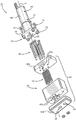
FIG. 9 is an exploded view of the pump assembly shown in FIG. 7;
FIG. 10 is a cross-sectional view of the pump assembly shown in FIG. 7;
FIG. 11 is a perspective view of a gear assembly used in the pump assembly shown in FIGS. 7-10;
FIG. 12 is a perspective view of an alternative pump assembly that can be used in the applicator shown in FIG. 1;
FIG. 13 is an exploded view of the pump assembly shown in FIG. 12;
fig. 14 is a side perspective view of the applicator shown in fig. 1, with a first nozzle assembly attached to the manifold;
figure 15 is a front perspective view of a portion of the applicator shown in figure 14;
fig. 16 is a bottom perspective view of a portion of the applicator shown in fig. 14;
FIG. 17A is an exploded view of the first nozzle assembly shown in FIG. 14;
FIG. 17B is an alternative exploded view of the first nozzle assembly shown in FIG. 14;
fig. 18 is a side perspective view of the applicator shown in fig. 1, with a second nozzle assembly attached to the manifold;
figure 19 is a front perspective view of a portion of the applicator shown in figure 18;
figure 20 is a rear perspective view of a portion of the applicator shown in figure 18;
FIG. 21A is a perspective view of the first clamp shown in FIG. 18;
FIG. 21B is a perspective view of the second clamp shown in FIG. 18;
FIG. 21C is a perspective view of the nozzle shown in FIG. 18; and is
Fig. 21D is a perspective view of the plate shown in fig. 18.
Detailed Description
An applicator 10 is described herein, the applicator 10 including a manifold 12 compatible with different nozzles. The manifold 12 defines a body 13, the body 13 defining a first contact surface 39 and a recess 18, the recess 18 being defined by a second contact surface 18a and a third contact surface 18 b. The first contact surface 39, the second contact surface 18a, and the third contact surface 18b are configured to interchangeably engage multiple types of nozzle assemblies, such as the first nozzle assembly 100 and the second nozzle assembly 200. In the following description, certain terminology is used to describe applicator 10 for convenience and is not limiting. The words "right", "left", "lower" and "upper" designate directions in the drawings to which reference is made. The words "inner" and "outer" refer to directions toward and away from, respectively, the geometric center of the description describing applicator 10 and its associated parts. The words "forward" and "rearward" refer to a direction along longitudinal direction 2 and a direction opposite to longitudinal direction 2 along applicator 10 and its associated parts. The terminology includes the words listed above, derivatives thereof and words of similar import.
Unless otherwise specified herein, the terms "longitudinal," "vertical," and "transverse" are used to describe orthogonal directional components of the various components of applicator 10, as represented by longitudinal direction 2, transverse direction 4, and vertical direction 7. It should be understood that although the longitudinal direction 2 and the transverse direction 4 are shown as extending along a horizontal plane and the vertical direction 6 is shown as extending along a vertical plane, the planes containing the respective directions may be different during use.
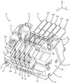
Embodiments of the present invention include an applicator 10 for dispensing adhesive onto a substrate during product manufacture. Referring to fig. 1-6, applicator 10 includes a manifold 12. The applicator 10 has: a top surface 32; a bottom surface 30, the bottom surface 30 being opposite the top surface 32 in the vertical direction 6; the first side surface 34 a; a second side surface 34b, the second side surface 34b being opposite to the first side surface 34a in the transverse direction 4; a front surface 36; and a rear surface 38, the rear surface 38 being opposite the front surface 36 in the longitudinal direction 2. The first and second side surfaces 34a, 34b extend from the front surface 36 to the rear surface 38 and from the bottom surface 30 to the top surface 32. The manifold 12 includes a main body 13, the main body 13 being defined by a first end plate 24, a second end plate 26, and at least one manifold section 22 disposed between the first and second end plates 24, 26. As a result, the first and second end plates 24, 26 are spaced apart in the transverse direction 4. First and second end plates 24, 26 and manifold section 22 may be releasably connected so that additional manifold sections 22 may be added to or removed from applicator 10 as required by operating conditions. As a result, although fig. 1-5 illustrate applicator 10 as including one manifold section 22, applicator 10 may include more manifold sections 22 as desired. However, in another embodiment, the manifold 12 may be a one-piece manifold.
Referring to fig. 2-4, the first side surface 34a of the manifold 12 lies within a first plane P1, while the second side surface 34b lies within a second plane P2. The second plane P2 may be parallel to the first plane P1. However, if the first and second side surfaces 34a and 34b are angled with respect to each other, the first and second planes P1 and P2 may not be parallel. Applicator 10 defines a horizontal plane X such that longitudinal direction 2 and transverse direction 4 lie within horizontal plane X. The pump assembly 20 may define a drive shaft axis a that lies within a plane Y. The interrelationship of these planes and axes will be described further below.
As described below, applicator 10 also defines features that allow different nozzle assemblies 100 or 200 to be removably attached to manifold 12. The body 13 of the manifold 12 defines a first contact surface 39 and a bore 37, the bore 37 extending from the first contact surface 39 into the manifold 12. The bore 37 may receive a fastener, such as the first clamp 104 or 204, that secures a portion of the first nozzle assembly 100 or the second nozzle assembly 200 to the manifold 12. Any number of holes 37 may be included in the manifold 12 depending on the particular range of nozzle assemblies that may be used with the manifold 12. Although the front surface 36 is depicted as including the first contact surface 39, the first contact surface 39 may be spaced from the front surface 36 as desired. For example, the first contact surface 39 may be spaced apart from the front surface 36 along the longitudinal direction 2.
Further, the manifold 12 may define a recess 18, the recess 18 extending from the bottom surface 30 into the manifold 12 in the vertical direction 6. The recess 18 may also extend from the front surface 36 into the manifold 12 in the longitudinal direction 2. The recess 18 may also extend from the first side surface 34a to the second side surface 34 b. As described further below, the recess 18 is configured to receive features of the nozzle assemblies 100 and 200. The manifold 12 may define a second contact surface 18a and a third contact surface 18b, wherein the second contact surface 18a extends from the first contact surface 39 to the second side surface 34b, and the third contact surface 18b extends from the second contact surface 18a to the bottom surface 30, and each of the second contact surface 18a and the third contact surface 18b partially defines the recess 18. The first contact surface 39 may be angularly offset from the second contact surface 18a, and the second contact surface 18a may be angularly offset from the third contact surface 18 b. In one embodiment, the second contact surface 18a is substantially perpendicular to the third contact surface 18 b. Similar to the first contact surface 39, the second contact surface 18a may include an aperture 31, the aperture 31 extending from the second contact surface 18a into the manifold 12, and the aperture 31 configured to receive a fastener, such as a second clamp 108, that secures a portion of the nozzle assemblies 100 and 200 to the manifold 12. The second contact surface 18a may be spaced apart from the bottom surface 30 of the manifold 12 along the vertical direction 6.
Continuing with fig. 1-6, applicator 10 includes an input connector 14 through which input connector 14 adhesive is pumped into manifold 12. The manifold 12 may further include: a pressure relief valve 17, the pressure relief valve 17 allowing a user to relieve pressure generated by the adhesive within the manifold; and a dispensing module 16, the dispensing module 16 for applying adhesive to a substrate. When the pressure relief valve 17 is opened, the adhesive may be discharged from the manifold through a discharge tube (not shown). Applicator 10 further includes a pump assembly 20, the pump assembly 20 being removably mounted to manifold 12. The pump assembly 20 pumps adhesive flowing from the internal passage of the manifold 12 to the dispensing module 16, and the dispensing module 16 then dispenses adhesive from the applicator through the first nozzle assembly 100 or the second nozzle assembly 200, as will be discussed further below. Applicator 10 may include a thermal element 23, which thermal element 23 is configured to raise the temperature of manifold 12, which in turn raises the temperature of pump 40 in each pump assembly 20. Although fig. 1-6 depict applicator 10 as including four thermal elements 23 a-23 d, any number of thermal elements 23 may be included as desired.
In various embodiments, applicator 10 includes multiple sets of pump assemblies 20 and dispensing modules 16. As shown in fig. 1-6, for example, applicator 10 is depicted as including five pump assemblies 20a, 20b, 20c, 20d, and 20 e. Although fig. 1-6 show five pump assemblies 20 a-20 e, applicator 10 may include any number of pump assemblies 20 as desired. For example, applicator 10 may include two pump assemblies, three pump assemblies, or more than three pump assemblies. The pump assemblies 20 a-20 e can be arranged in a side-by-side configuration to increase the treatment width of the applicator 10. For clarity, a single pump assembly 20 is described below. However, the reference numeral 20 may be used interchangeably with the reference numerals 20a to 20 e. While pump assemblies 20 a-20 d are depicted as having similar dimensions, and pump assembly 20e is depicted as being larger than pump assemblies 20 a-20 d, each of the individual pump assemblies 20 included in applicator 10 can be individually sized as needed to suit a particular application.
In addition, applicator 10 is depicted as including four dispensing modules 16a, 16b, 16c, and 16 d. Although fig. 1-6 illustrate four dispensing modules 16 a-16 d, applicator 10 may include any number of dispensing modules 16, as desired. For example, applicator 10 may include one dispensing module, two dispensing modules, or more than two dispensing modules. Similarly, a single dispensing module 16 is described below. However, the reference numeral 16 may be used interchangeably with the reference numerals 16a to 16 d.
Continuing with fig. 1-6, each of the pump assemblies 20 a-20 e may be associated with a corresponding one of the dispensing modules 16 a-16 e. In operation, each of the pump assemblies 20 a-20 e may pump fluid supplied by the manifold 12 to a corresponding one of the dispensing modules 16 a-16 d such that the dispensing modules 16 a-16 d apply adhesive to a given substrate. However, each dispensing module 16 may not correspond to a single pump assembly 20, such that multiple pump assemblies 20 pump adhesive to a single dispensing module 16.
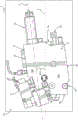
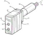
Referring to fig. 7-11, each of the pump assemblies 20 a-20 e includes a pump 40 and a dedicated drive motor unit 60, the dedicated drive motor unit 60 powering the pump 40. Because each pump 40 has a dedicated drive motor unit 60, each pump assembly 20 can be independently controlled by an operator and/or a control system (not shown). The pump assembly 20 also includes an insulated region 70, the insulated region 70 being located between the pump 40 and the drive motor unit 60. The thermal element 23 may be used to raise the temperature of the manifold 12, which in turn raises the temperature of the pump 40 in each pump assembly 20. The insulated region 70 minimizes heat transfer from the pump 40 to the drive motor unit 60, thereby minimizing the effect of temperature on the electronic components in the drive motor unit 60. Exposing the electronic components in the drive motor unit 60 to a sufficiently high temperature may damage the electronic components, which may render the drive motor unit 60 inoperable.
The drive motor unit 60 includes a motor 62, an output drive shaft 66, and one or more connectors (not shown) coupled to a power source (not shown). The drive motor unit 60 is coupled to a gear assembly 67, which gear assembly 67 may comprise any type of gear that transfers rotational motion from the motor's output drive shaft 66 to the pump's input drive shaft (not shown) to achieve a desired rotational speed, as desired. In one embodiment, the gear assembly 67 includes a planetary gear train. The output drive shaft 66 has a drive axis a about which the drive shaft 66 rotates.
Referring back to fig. 3 and 4, the pump assembly 20 can be mounted to the manifold 12 in a variety of different configurations. In one embodiment, the pump assembly 20 is mounted to the manifold 12 such that the bottom surface 41 of the pump 40 (the bottom surface 41 including the inlet 52 and the outlet 54) faces the manifold 12 at a location between the first and second side surfaces 34a, 34b and spaced apart from the first and second side surfaces 34a, 34 b. In this configuration, the drive motor axis a does not intersect the first side surface 34a or the second side surface 34b of the applicator 10. Rather, the pump assembly 20 is positioned on the manifold 12 such that the drive motor axis a of the drive motor unit 60 may lie in a plane Y that is parallel to the first plane P1 in which the first side surface 34a lies, as described above. The plane Y may also be parallel to a second plane P2 on which the second side surface 34b lies. Each of the pump assemblies 20 a-20 e has a respective axis a that lies within a respective plane that may be parallel to the first plane P1 and/or the second plane P2.
Continuing with fig. 3 and 4, the pump assembly 20 is positioned on the manifold 12 such that the drive motor axis a is oriented in any particular direction within the plane Y. For example, the pump assembly 20 may be positioned on the manifold such that the drive motor axis a lies within the plane Y and is angularly offset relative to the plane X. For example, the pump assembly 20 may be positioned on the manifold 12 such that the drive motor axis a defines an angle θ relative to the plane X. The angle θ may be any angle as desired. In one embodiment, the angle θ is an acute angle. Alternatively, the angle θ may be an obtuse angle, an angle greater than 180 degrees, or substantially 90 degrees.
Referring to fig. 7-11, the pump 40 includes a housing assembly 42 and a gear assembly 50, the gear assembly 50 being housed within the housing assembly 42. Alternatively, more than one gear assembly 50 may be housed within the housing assembly 42. The housing assembly 42 also includes an inlet 52 configured to receive adhesive from the manifold segment 22, and an outlet 54 for discharging adhesive back into the manifold segment 22. According to the embodiment shown in fig. 7-11, the inlet 52 and the outlet 54 of the pump 40 are defined by the bottom surface 41 of the pump 40 and are oriented in a direction parallel to the drive motor axis a of the drive motor unit 60.
The housing assembly 42 includes an upper plate 44a, a lower plate 44b, and a center block 46. The upper plate 44a and the lower plate 44b are spaced apart from each other in a direction aligned with the drive axis a of the drive motor unit 60. The lower plate 44b defines a bottom surface 41, and the drive axis a may extend through the bottom surface 41. The upper plate 44a, the center block 46, and the lower plate 44b are coupled together by bolts 48. The upper plate 44a has a plurality of holes 49a configured to receive bolts 48, the center block 46 has a plurality of holes 49b configured to receive bolts 48, and the lower plate 44b has a plurality of holes (not shown) configured to receive bolts 48. The bolt 48, the hole 49a and the hole 49b may be threaded such that the holes 49a to 49b can threadedly receive the bolt 48.
The center block 46 has an interior cavity 56, the interior cavity 56 being sized to generally conform to the contour of the gear assembly 50. In one embodiment, the gear assembly 50 includes a driven gear 55a and an idler gear 55b, which are known to those of ordinary skill in the art. The driven gear 55a is coupled to an output drive shaft 66 of the drive motor unit 60 such that rotation of the drive shaft 66 rotates the driven gear 55a, which in turn rotates the idler gear 55 b. The driven gear 55a surrounds the first axis A1Rotates while the idler gear 55b surrounds the secondAxis A2And (4) rotating. In fig. 10, a first axis a1Shown coaxial with the drive motor axis a. However, it is also conceivable for the first axis a to be1May be offset from the drive motor axis a. The gear assembly 50 may include an elongated gear shaft (not shown) coupled to an end of the output drive shaft 66 via a coupling (not shown). The gear shaft may extend into the driven gear 55a, and may be keyed to actuate the driven gear 55 a. A sealing member (not shown), such as a coating and/or a jacket, may be placed around the elongated gear shaft to facilitate sealing of the gear assembly 50 and the internal cavity 56.
In use, rotation of the driven gear 55a and idler gear 55b drives adhesive in the pump 40 from the first section 58a of the internal chamber 56 to the second section 58b of the internal chamber 56. The adhesive then travels from the second section 58b of the interior chamber 56 to the outlet 54. According to the illustrated embodiment, the driven gear 55a has a diameter D1And length L1Wherein the length L1May be greater than the diameter D1. Likewise, idler gear 55b has a diameter D2And length L2Wherein the length L2May be greater than the diameter D2. Although a gear assembly 50 having two gears is shown, the pump may have a gear assembly having any number of gear configurations to produce the desired adhesive flow rate through the pump 40. In these configurations, the center block 46 may be segmented to support the gear stack. In one embodiment, a plurality of gear assemblies (not shown) may be stacked along the pump input shaft. In this embodiment, the gear assembly may have different outputs that are combined into a single output flow. In another embodiment, the gear assembly has different outputs that can be kept separate to provide multiple outputs through additional ports in the lower plate 44b and manifold 12.
Continuing with fig. 7-11, the insulation area 70 is defined by an insulation plate 72 and a gap 74, the gap 74 extending from the insulation plate 72 to the housing assembly 42. The pump assembly 20 includes bolts 75 that couple the heat shield 72 to the top of the housing assembly 42 such that a gap 74 is formed between the housing assembly 42 and the heat shield 72. The heat shield plate 72 may include a plurality of spacers 76, the plurality of spacers 76 being disposed around the bolt 75 and between a surface of the heat shield plate 72 and the upper plate 44a of the housing assembly 42. The spacer 76 may be integrally formed with the heat shield plate 72 or may be separate from the heat shield plate 72 such that the gap 74 may be adjustable. Spacers 76 may extend inwardly from the upper plate 44a to ensure that the motor output shaft 66 is aligned with the driven gear 55 a. The heat insulation plate 72 serves to suppress heat transfer from the pump 40 to the drive motor unit 60. For this reason, the heat insulation plate 72 and the spacer 76 are made of a material having a lower thermal conductivity than the adhesive forming the components of the housing assembly 42 and the casing 61 of the drive motor unit 60. In addition, the spacer 76 separates the heat shield 72 and the housing assembly 42 such that the heat shield 72 and the housing assembly 42 have a gap 74, which minimizes direct contact between the housing assembly 42 and the drive motor unit 60.
Referring to fig. 3, each of the pump assemblies 20 a-20 e is removably attached to the manifold 12. In one embodiment, each pump assembly 20 is secured to a plate 28 via fasteners 27. The plate 28 is attached at one end to the first end plate 24 via a fastener 29 and at the other end to the second end plate 26 via another fastener 29. Fasteners 29 may also attach plate 28 to manifold section 22. The fasteners 27 may be threaded such that removal of the pump assembly 20 from the manifold 12 requires unscrewing the fasteners 27 from the pump assembly 20 and then removing the pump assembly 20 from the manifold 12. However, other methods of releasably attaching the pump assembly 20 to the manifold 12 are contemplated, such as a slot or groove system, snap-fit engagement, or the like. Because the pump assembly 20 can be releasably coupled to the manifold 12 in the manner described above, a particular pump assembly 20 can be individually replaced without completely disassembling the entire applicator 10. The pump assembly 20 may need to be replaced for a variety of reasons, including cleaning, damage, or altered adhesive pumping conditions or requirements.
Fig. 12 to 13 show another embodiment of the present invention. Fig. 12 illustrates a pump assembly 120, which pump assembly 120 is similar in most respects to the pump assembly 20 illustrated in fig. 1-9 and described above. However, the pump assembly 120 has an inlet 152 and an outlet 154, the inlet 152 and outlet 154 being oriented differently than the inlet 52 and outlet 54 of the pump assembly 20. The pump assembly 120 is configured to supply heated liquid to the manifold 12 at a given volumetric flow rate. Each pump assembly 120 includes a pump 140 and a dedicated drive motor unit 160, the dedicated drive motor unit 160 powering the pump 140. The pump assembly 120 also includes an insulated region 170, the insulated region 170 being between the pump 140 and the drive motor unit 160. The insulated region 170 is defined by an insulated plate 172 and a gap 174, the gap 174 extending from the insulated plate 172 to the housing assembly 142. The heat insulation region 170 minimizes heat transfer from the heat generated by the pump 140 to the drive motor unit 160, thereby minimizing the effect of temperature on the electronic components in the drive motor unit 160. The dedicated drive motor unit 160 and the thermally insulated region 170 are the same as the drive motor unit 60 and the thermally insulated region 70 shown in fig. 7 to 10 described above.
Continuing with fig. 12-13, the drive motor unit 160 includes a motor 162, an output drive shaft 166, and a connector (not shown) that is coupled to a power source (not shown) and a control system (not shown). The drive shaft 166 has a drive axis B about which the drive shaft 166 rotates. When the pump assembly 120 is coupled to the manifold 12, the drive axis B may intersect a plane X that is perpendicular to the plane Y and may be angularly offset relative to the plane X. In this configuration, the drive motor axis B does not intersect the first side surface 34a or the second side surface 34B of the manifold 12. In addition, the drive motor axis B does not intersect the bottom surface 30 of the manifold 12. Rather, the pump assembly 120 is positioned on the manifold 12 such that the drive motor axis B of the drive motor unit 160 lies in a plane Y that is parallel to the first and/or second planes P1 and P2 of the first and second side surfaces 34a and 34B, respectively.
The pump 140 defines a bottom surface 141 and a side surface 143, and includes a housing assembly 142 and one or more gear assemblies 150 housed within the housing assembly 142, an inlet 152 for receiving liquid from the manifold 12, and an outlet 154 for discharging liquid back into the manifold 12. According to the illustrated embodiment, the inlet 152 and the outlet 154 of the pump 140 are disposed on the side surface 143 of the pump 140 such that the inlet 152 and the outlet 154 are oriented in a direction perpendicular to the drive motor axis B of the drive motor unit 160.
Referring now to fig. 14-17B, one embodiment of a nozzle assembly that may be connected to applicator 10 will be described. The first nozzle assembly 100 may include a first clamp 104, a second clamp 108, and a nozzle 110. In this embodiment, the nozzle 110 may comprise two separate plates, a first nozzle plate 112 and a second nozzle plate 116, separated by a spacer 114. The spacer 114 serves to separate the first nozzle plate 112 from the second nozzle plate 116 such that a gap is defined between the first nozzle plate 112 and the second nozzle plate 116. This gap between the first and second nozzle plates 112, 116 defines a nozzle slot 120 through which adhesive can exit the applicator 10 and be applied to a substrate through the nozzle slot 120. As a result, the first nozzle assembly 100 may be a liquid adhesive contact nozzle assembly suitable for adhesive coating applications. The first clamp 104 and the second clamp 108 may be used to secure the nozzle 110 to the manifold 12. In particular, the first and second clamps 104, 108 may be used to directly engage the second nozzle plate 116 of the nozzle 110 to secure the nozzle 110 to the manifold 12.
The first clamp 104 may include a plurality of holes configured to receive fasteners that secure the first clamp 104 to the manifold 12 and the nozzle 110. For example, the first clamp 104 includes a plurality of first clamp manifold holes 124, the plurality of first clamp manifold holes 124 extending through the first clamp 104 and each configured to receive a fastener 125. In the depicted embodiment, the first clamp 104 defines six first clamp manifold holes 124 a-124 f, which six first clamp manifold holes 124 a-124 f may be designated as a first clamp manifold hole 124a, a second first clamp manifold hole 124b, a third first clamp manifold hole 124c, a fourth first clamp manifold hole 124d, a fifth first clamp manifold hole 124e, and a sixth first clamp manifold hole 124 f. However, the first clamp 104 may define more or less than six first clamp manifold holes 124 as desired. For example, the first clamp 104 may define one, two, or more than six first clamp manifold holes 124. As described, each of the first clamp manifold holes 124 a-124 f may be configured to receive a fastener 125. The fasteners 125 may be screws, bolts, or any other type of fastener capable of releasably coupling the first clamp 104 to the manifold 12. However, it is contemplated that the fastener 125 may non-removably couple the first clamp 104 to the manifold 12.
The first clamp 104 may also include a plurality of first clamp nozzle holes 128, the plurality of first clamp nozzle holes 128 extending through the first clamp 104 and each configured to receive a fastener 129. In the depicted embodiment, the first clamp 104 defines three first clamp nozzle holes, which may be designated as a first clamp nozzle hole 128a, a second first clamp nozzle hole 128b, and a third first clamp nozzle hole 128 c. However, the first clamp 104 may define more or less than three first clamp nozzle orifices 128 as desired. For example, the first clamp 104 may define one, two, or more than three first clamp nozzle holes 128. As depicted, each of the first clamp nozzle orifices 128 a-128 c may be configured to receive a fastener 129. Similar to the fasteners 125, the fasteners 129 may be screws, bolts, or any other type of fastener capable of releasably coupling the first clamp 104 to the nozzle 110 (particularly the second nozzle plate 116). However, it is contemplated that the fastener 129 may non-removably couple the first clamp 104 to the nozzle 110.
Referring to fig. 17A-17B, the first clamp 104 may include a body defining a plurality of surfaces. In the illustrated embodiment, the first clamp 104 defines: a first surface 104 a; a second surface 104b, the second surface 104b extending from the first surface 104 a; and a third surface 104c, the third surface 104c extending from the second surface 104 b. The first surface 104a may extend substantially perpendicular to the vertical direction 6 and may be configured to contact a portion of the manifold 12 when the first nozzle assembly 100 is attached to the manifold 12. The second surface 104b may be angularly offset relative to the manifold 12 and may define a first opening for each of the first clamp manifold holes 124 a-124 f. The third surface 104c may be angularly offset relative to the second surface 104b and may define an opening for each of the first clamp nozzle orifices 128 a-128 c.
The first clamp 104 may further define: a fourth surface 104d, the fourth surface 104d extending from the third surface 104 c; a fifth surface 104e, the fifth surface 104e extending from the fourth surface 104 d; a sixth surface 104f, the sixth surface 104f extending from the fifth surface 104 e; and a seventh surface 104g, the seventh surface 104g extending from the sixth surface 104f to the first surface 104 a. The fourth surface 104d can be substantially perpendicular to the third surface 104c and the fifth surface 104e, and the fourth surface 104d can partially contact the nozzles 110, particularly the first nozzle plate 112, when the first nozzle assembly 100 is fully assembled. Likewise, the fifth surface 104e of the first clamp 104 may also contact the nozzle assembly 100, in particular the second nozzle plate 116, when the first nozzle assembly 100 is fully assembled. The fifth surface 104e may define a second opening for each of the first clamp nozzle holes 128 a-128 c such that the first clamp nozzle holes 128 a-128 c extend through the body of the first clamp 104 from the third surface 104c to the fifth surface 104 e. The sixth surface 104f may be angularly offset relative to the fifth surface 104 e. In the depicted embodiment, the sixth surface 104f is offset from the fifth surface 104e by an angle less than 90 degrees. The sixth surface 104f may also be configured to engage a portion of the nozzle 110, particularly the second nozzle plate 116, when the first nozzle assembly 100 is fully assembled. The seventh surface 104g may be substantially perpendicular to the first surface 104a and may define a second opening for each of the first clamp manifold holes 124 a-124 f, such that the first clamp manifold holes 124 a-124 f extend through the body of the first clamp 104 from the second surface 104b to the seventh surface 104 g. The seventh surface 104g of the first clamp 104 may be configured to engage a portion of the manifold 12 when the first nozzle assembly 100 is in the assembled configuration.
The first clamp 104 may also define first and second side surfaces, which may be designated as eighth and ninth surfaces 104h and 104 i. The eighth surface 104h and the ninth surface 104i of the first clamp 104 may each extend between each of the first surface 104a to the seventh surface 104g such that each of the surfaces 104a to 104g extends from the eighth surface 104h to the ninth surface 104 i. As a result, the eighth surface 104h may be substantially opposite the ninth surface 104 i.
Similar to the first clamp 104, the second clamp 108 may include a plurality of holes configured to receive fasteners that secure the second clamp 108 to the manifold 12. For example, the second clamp 108 includes a plurality of second clamp holes 136, the plurality of second clamp holes 136 extending through the second clamp 108 and each configured to receive a fastener 137. As shown, the second clamp 108 defines six second clamp holes 136, which six second clamp holes 136 may be designated as a first second clamp hole 136a, a second clamp hole 136b, a third second clamp hole 136c, a fourth second clamp hole 136d, a fifth second clamp hole 136e, and a sixth second clamp hole 136 f. However, the second clamp 108 may define more or less than six second clamp apertures 136 as desired. For example, the second clamp 108 may define one, two, or more than six second clamp manifold holes 136. As noted, each of the second clamp holes 136 a-136 f may be configured to receive a fastener 137. Similar to the fasteners 125 and 129, the fasteners 137 may be screws, bolts, or any other type of fastener capable of releasably coupling the second clamp 108 to the manifold 12. However, it is contemplated that the fastener 137 may non-removably couple the second clamp 108 to the manifold 12.
Continuing with fig. 17A-17B, the second clamp 108 may further define a body defining a plurality of surfaces. In the illustrated embodiment, the second clamp 108 defines: a first surface 108 a; a second surface 108b, the second surface 108b extending from the first surface 108 a; a third surface 108c, the third surface 108c extending from the second surface 108 b; and a fourth surface 108d, the fourth surface 108d extending from the third surface 108c to the first surface 108 a. The first surface 108a may extend substantially perpendicular to the vertical direction 6 and may be configured to contact a portion of the manifold 12 when the first nozzle assembly 100 is attached to the manifold 12. The first surface 108a may also define a first opening for each of the second clamp holes 136 a-136 f. The second surface 108b can be angularly offset relative to the first surface 108a and can be configured to engage a portion of the nozzle 110, particularly the second nozzle plate 116. The third surface 108c may be generally opposite the first surface 108a and may be angularly offset from the second surface 108 b. The third surface 108c may also define a second opening for each of the second clamp apertures 136 a-136 f, such that the second clamp apertures 136 a-136 f extend through the body of the second clamp 108 from the third surface 108c to the first surface 108 a. The fourth surface 108d may be substantially perpendicular to the third surface 108c and the first surface 108a, and may be configured to engage a portion of the manifold 12 when the first nozzle assembly 100 is attached to the manifold 12. The second clamp 108 may also define first and second side surfaces, which may be designated as fifth and sixth surfaces 108e and 108 f. The fifth surface 108e and the sixth surface 108f of the second clamp 108 may extend between each of the first surface 108a to the fourth surface 108d such that each of the surfaces 104a to 104d extends from the fifth surface 104e to the sixth surface 104 f. As a result, the fifth surface 108e may be substantially opposite the sixth surface 108 f.
As described above, the nozzles 110 may include the first nozzle plate 112, the spacer 114, and the second nozzle plate 116. The nozzles 110 can be configured such that the first and second nozzle plates 112, 116 and the shim 114 are releasably coupled to one another. For example, the first nozzle plate 112 can define a plurality of first nozzle holes 132, the plurality of first nozzle holes 132 configured to receive fasteners 133, the fasteners 133 securing the first nozzle plate 112 to the spacer 114 and the second nozzle plate 116. As shown, the first nozzle plate 112 may include four first nozzle holes 132, and the four first nozzle holes 132 may be designated as first nozzle holes 132a, second first nozzle holes 132b, third first nozzle holes 132c, and fourth first nozzle holes 132 d. However, the first nozzle plate 112 may define more or less than four first nozzle holes 132 as desired. For example, the first nozzle plate 112 may define one, two, or more than four first nozzle holes 132. As described, each of the first nozzle holes 132a to 132d may be configured to receive the fastener 133. The fasteners 133 may be screws, bolts, or any other type of fastener capable of releasably coupling the first nozzle plate 112 to the second nozzle plate 116. However, it is contemplated that the fasteners 133 can non-removably couple the first nozzle plate 112 to the second nozzle plate 116.
The first nozzle plate 112 of the nozzle 110 can also include a body that defines a plurality of surfaces. In the illustrated embodiment, the first nozzle plate 112 defines: a first surface 112 a; a second surface 112b, the second surface 112b extending from the first surface 112 a; a third surface 112c, the third surface 112c extending from the second surface 112 b; and a fourth surface 112d, the fourth surface 112d extending from the third surface 112c to the first surface 112 a. The first surface 112a can extend substantially perpendicular to the vertical direction 6 and can be configured to contact a portion of the second nozzle plate 116 when the nozzle 110 is fully assembled. The second surface 112b may be angularly offset from the first surface 112a and may define a first opening for each of the first nozzle holes 132 a-132 d. The third surface 112c may be opposite the first surface 112a and angularly offset, such as obtusely offset, from the second surface 112 b. The fourth surface 112d may be opposite the second surface 112b and may define a second opening for each of the first nozzle holes 132a to 132d such that the first nozzle holes 132a to 132d extend through the body of the first nozzle plate 112 from the second surface 112b to the fourth surface 112 d. In addition, the first nozzle plate 112 may define first and second side surfaces, which may be designated as fifth and sixth surfaces 112e and 112 f. The fifth surface 112e and the sixth surface 112f of the first nozzle plate 112 may each extend between each of the first surface 104a to the fourth surface 104d such that each of the four surfaces 104a to 104d extends from the fifth surface 104e to the sixth surface 104 f. As a result, the fifth surface 112e may be substantially opposite the sixth surface 112 f.
Continuing with fig. 17A-17B, the second nozzle plate 116 can define a plurality of second nozzle holes 190, each of the plurality of second nozzle holes 190 being configured to receive a portion of a respective fastener 133, the fastener 133 securing the first nozzle plate 112 to the spacer 114 and the second nozzle plate 116. As shown, the second nozzle plate 116 defines four second nozzle holes 190, which four second nozzle holes 190 may be designated as first second nozzle holes 190a, second nozzle holes 190b, third second nozzle holes 190c, and fourth second nozzle holes (one of the nozzle holes not shown). However, the second nozzle plate 116 may define more or less than four second nozzle holes 140 as desired. For example, the second nozzle plate 116 may define one, two, or more than four second nozzle holes 190. The number of second nozzle holes 190 defined by the second nozzle plate 116 can generally be correlated to the number of first nozzle holes 132 defined by the first nozzle plate 112.
Additionally, the second nozzle plate 116 of the nozzle 110 can define a body that includes a plurality of surfaces. In the illustrated embodiment, the second nozzle plate 116 defines: a first surface 116 a; a second surface 116b, the second surface 116b extending from the first surface 116 a; a third surface 116c, the third surface 116c extending from the second surface 116 b; a fourth surface 116d, the fourth surface 116d extending from the third surface 116 c; a fifth surface 116e, the fifth surface 116e extending from the fourth surface 116 d; a sixth surface 116f, the sixth surface 116f extending from the fifth surface 116 e; a seventh surface 116g, the seventh surface 116g extending from the sixth surface 116 f; an eighth surface 116h, the eighth surface 116h extending from the seventh surface 116g to the first surface 116 a. The first surface 116a may extend substantially perpendicular to the vertical direction 6 and may be configured to contact a portion of the manifold 12 when the first nozzle assembly 100 is attached to the manifold 12. The first surface 116a may also be configured to engage a portion of the first clamp 104 when the first nozzle assembly 100 is attached to the manifold 12. The second surface 116b may be angularly offset relative to the first surface 116a and may also be configured to engage the first clamp 104 when the first nozzle assembly 100 is attached to the manifold 12. The third surface 116c may be angularly offset relative to the second surface 116b and may be generally opposite the first surface 116 a. The third surface 116c can also be configured to engage the first nozzle plate 112 when the nozzle 110 is fully assembled.
With continued reference to fig. 17A-17B, the fourth surface 116d of the second nozzle plate 116 can be angularly offset from the third surface 116c and can also be configured to engage the spacer 114 when the nozzle 110 is fully assembled. In addition, the fourth surface 116d may define a first opening for the second nozzle hole 190. The fifth surface 116e may be generally opposite the first surface 116a and may be curved. The sixth surface 116f may be generally opposite the fourth surface 116d and may define a second opening for the second nozzle hole 190 such that the second nozzle hole 190 extends from the fourth surface 116d to the sixth surface 116f through the second nozzle plate 116. The seventh surface 116g may be angularly offset from the sixth and eighth surfaces 116f, 116h, and may be generally opposite the first surface 116 a. The eighth surface 116h may be angularly offset from the first surface 116a and may be configured to engage the second clamp 108 when the first nozzle assembly 100 is attached to the manifold 12. The eighth surface 116h may also be opposite the second surface 116b in the longitudinal direction 2 and angularly offset from the second surface 116 b.
The second nozzle plate 116 can also define first and second side surfaces, which can be designated as ninth and tenth surfaces 116i and 116 j. The ninth surface 116i and the tenth surface 116j of the second nozzle plate 116 may extend between each of the first surface 116a to the eighth surface 116h such that each of the eight surfaces 116a to 116h extends from the ninth surface 116i to the tenth surface 116 j. As a result, the ninth surface 116i may be substantially opposite the sixth surface 116 f.
Continuing with fig. 17A-17B, when the nozzles 110 are in an assembled configuration, a shim 114 can be disposed between the first and second nozzle plates 112, 116. The shim 114 may be generally planar and may have a first surface 114a and a second surface 114b, the second surface 114b being opposite the first surface 114 a. When the nozzles 110 are assembled, the first surface 114a of the spacer 114 contacts the fourth surface 112d of the first nozzle plate 112, and the second surface 114b of the spacer 114 contacts the fourth surface 116d of the second nozzle plate 116. As a result, the spacer 114 creates a gap between the first nozzle plate 112 and the second nozzle plate 116. The shim 114 also defines a plurality of notches 117 that, together with the gap created by the shim 114 between the first and second nozzle plates 112, 116, define a nozzle slot 120. Although depicted as defining four notches 117, the shim 114 may alternatively define any number of notches 117 as desired, depending on the particular nozzle slot 120 desired. The shim 114 also defines a shim hole 115, the shim hole 115 extending from the first surface 114a to the second surface 114b and configured to receive a fastener 133, the fastener 133 allowing the shim 114 to be secured to the first and second nozzle plates 112, 116.
The interaction of the various parts of the first nozzle assembly 100 when the first nozzle assembly 100 is secured to the manifold 12 will now be described. As shown in fig. 13-15, when the first nozzle assembly 100 is attached to the manifold 12, the nozzles 110 are assembled by securing the first nozzle plate 112 to the shim 114 and the second nozzle plate 116. This is accomplished by inserting fasteners 133 through the first nozzle holes 132a through 132d of the first nozzle plate 112, through the spacer holes 115 of the spacer 114, and through the second nozzle holes 140a through 140d of the second nozzle plate 116. When assembled, the first surface 112a of the first nozzle plate 112 contacts the third surface 116c of the second nozzle plate 116, and the fourth surface 112d of the first nozzle plate 112 contacts the first surface 114a of the spacer 114. Collectively, the first and second nozzle plates 112, 116 and the shim 114 (particularly the recess 117 of the shim 114) can define, along with a gap formed by the shim 114 between the fourth surface 112d of the first nozzle plate 112 and the fourth surface 116d of the second nozzle plate 116, a nozzle slot 120, the nozzle slot 120 defining a path for adhesive to flow from the nozzles 110.
Once assembled, the nozzle 110 may be attached to the manifold 12 along with the first and second clamps 104, 108. To secure the nozzle 110 to the manifold 12, the first clamp 104 engages the body 13 of the manifold 12 and a first side of the nozzle 110, while the second clamp 108 engages the body 13 of the manifold 12 and a second side of the nozzle 110. In the illustrated embodiment, both the first clamp 104 and the second clamp 108 engage the second nozzle plate 116, although other configurations are contemplated. To secure the nozzles 110 to the manifold 12, the sixth surface 104f of the first clamp 104 engages the first surface 116a of the second nozzle plate 116, and the fifth surface 104e of the first clamp 104 engages the second surface 116b of the second nozzle 116. In addition, the fourth surface 104d of the first clamp 104 may contact the second surface 112b of the first nozzle plate 112. The fifth and sixth surfaces 104e, 104f of the first clamp 104 may together exert an upward and rearward force on the nozzles 110, particularly the second nozzle plate 116, to hold the nozzles 110 in engagement with the manifold 12. To maintain this engagement, a fastener 125 is inserted through the first clamp manifold holes 124 a-124 c of the first clamp 104 and the bore 37 of the manifold, and thus the fastener 125 is secured to the manifold 12 such that the first contact surface 39 of the manifold 12 engages the first surface 104a of the first clamp 104. Further, a fastener 129 is inserted through the first jig nozzle holes 128a to 128c and the fastener 129 is fixed to the nozzle 110, particularly the second nozzle plate 116. In this configuration, the second contact surface 18a of the manifold 12 engages the first surface 116a of the second nozzle plate 116.
On the other side of the nozzle 110, a second clamp 108 engages a second nozzle plate 116 to apply an upward and forward force to the nozzle 110. As a result, the nozzle 110 is effectively wedged between the first clamp 104 and the second clamp 108. This wedging helps prevent leakage between the nozzle 110 and the manifold 12 and ensures adequate heat transfer from the manifold 12 to the nozzle 110. When the nozzles 110 and the second clamp 108 are connected to the manifold 12, the second surface 108b of the second clamp 108 engages the eighth surface 116h of the second nozzle plate 116. To maintain this engagement, a fastener 137 is inserted through the second clamp apertures 136 a-136 d of the second clamp 108 and through the aperture 31 of the manifold 12 such that the second contact surface 18a of the manifold 12 engages the first surface 108a of the second clamp 108. Additionally, the fourth surface 108d of the second clamp 108 may engage the third contact surface 18b of the manifold 12. As a result, when the first nozzle assembly 100 is fully assembled and attached to the manifold 12, at least a portion of the first nozzle assembly 100 is received in the recess 18 of the manifold 12.
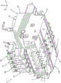
Referring now to fig. 18-21D, another embodiment of a nozzle assembly that may be connected to applicator 10 will be described. Second nozzle assembly 200 may include first fixture 204, second fixture 208, nozzle 212, and plate 216. Unlike the first nozzle assembly 100, each nozzle 212 of the second nozzle assembly 200 may comprise a single, unitary structure. As such, each nozzle 212 defines a nozzle slot 220, the nozzle slot 220 being configured to emit adhesive from the applicator 10. However, the second nozzle assembly 200 may define a plurality of nozzles 212. For example, the depicted embodiment includes four nozzles, which may be designated as a first nozzle 212a, a second nozzle 212b, a third nozzle 212c, and a fourth nozzle 212 d. Likewise, the second nozzle assembly 200 may include a plurality of first clamps 204 and a plurality of plates 216. For example, second nozzle assembly 200 may include four first clamps 204 and four plates 216, which four first clamps 204 and four plates 216 may be designated as first clamp 204a, second first clamp 204b, third first clamp 204c, fourth first clamp 204d, first plate 216a, second plate 216b, third plate 216c, and fourth plate 216 d. Each of the first clamps 204 a-204 d and the plates 216 a-216 d may correspond to a respective nozzle 212 a-212 d. Although four sets of first clamps 204 a-204 d, nozzles 212 a-212 d, and plates 216 a-216 d are shown and described, second nozzle assembly 200 may be configured to include more or less of these features. Additionally, although depicted as a single-piece structure, second fixture 208 may alternatively be configured as four separate second fixtures (not shown) such that each of the four second fixtures corresponds to a respective one of nozzles 212 a-212 d. The second nozzle assembly 200 may be a liquid adhesive spray nozzle assembly suitable for adhesive coating applications. First clamps 204 a-204 d, second clamps 208, and plates 216 a-216 d may be used to secure nozzles 212 a-212 d to manifold 12. In particular, the first and second clamps 204 a-204 d and 208 may be used to directly engage the nozzles 212 a-212 d to secure the nozzles 212 a-212 d to the manifold 12.
Referring to fig. 18-21A, each of the first clamps 204 a-204 d may define an aperture configured to receive a fastener that secures the first clamp 204 to the manifold 12 and the nozzles 212 a-212 d. For example, each of the first clamps 204 a-204 d may define an aperture 224, the aperture 224 extending through the first clamps 204 a-204 d and configured to receive a fastener 229. Although shown as including one aperture 224, each of the first clamps 204 a-204 d may define more than one aperture 224 as desired. For example, each of the first clamps 204 a-204 d may include two, three, or more than three holes. The fasteners 229 that may be received by the apertures 224 of the first clamps 204 a-204 d may be screws, bolts, or any other type of fastener capable of releasably coupling the first clamps 204 a-204 d to the manifold 12. However, it is contemplated that the fasteners 229 may non-removably couple the first clamps 204 a-204 d to the manifold 12.
Referring to fig. 21A, each of the first clamps 204a to 204d may include a body defining a plurality of surfaces. Although only one first clamp 204 is depicted, it may equally represent each of the first clamps 204 a-204 d. The first clamp 204 may define: a first surface 205 a; a second surface 205b, the second surface 205b extending from the first surface 205 a; a third surface 205c, the third surface 205c extending from the second surface 205 b; a fourth surface 205d, the fourth surface 205d extending from the third surface 205 c; a fifth surface 205e, the fifth surface 205e extending from the fourth surface 205 d; and a sixth surface 205f, the sixth surface 205f extending from the fifth surface 205e to the first surface 205 a. The first surface 205a may be generally curved, and the second surface 205b may be angularly offset from the first surface 205 a. The second surface 205b may also define a first opening for extending through the bore 224 of the body of the first clamp 204. The third surface 205c may be angularly offset from the second surface 205b and may define a forward opening for passage 230 extending through the first clamp 204. The fourth surface 205d may be generally opposite the first surface 205a and define a bottom opening for the channel 230. The fifth surface 205e may be curved and may define a rearward opening for the channel 230 such that the channel 230 extends from the third surface 205c to the fifth surface 205e through the first clip 204. The sixth surface 205f may be angularly offset from the fifth surface 205e and the first surface 205a, and may define a second opening for the aperture 224 such that the aperture 224 extends through the first clamp 204 from the second surface 205b to the sixth surface 205 f.
The first clamp 204 may also define first and second side surfaces, which may be designated as seventh and eighth surfaces 205g and 205 h. The seventh surface 205g and the eighth surface 205h may each extend between the first surface 205a to the sixth surface 205h such that each of the first surface 205a to the sixth surface 205h extends from the seventh surface 205g to the eighth surface 205 h. The first clamp 204 may also define a ninth surface 205i, the ninth surface 205i extending laterally upward from the fourth surface 205d of the first clamp 204 between the seventh surface 205g and the eighth surface 205 h. The ninth surface may generally define a channel 230, the channel 230 extending through the first clamp 204. A channel 230 may extend through a lower end of the first clamp 204 in the longitudinal direction 2 such that the first clamp 204 defines two arms 206a and 206 b. The first arm 206a and the second arm 206b may be spaced apart along the transverse direction 4. The first arm 206a may define a first passage 228a, the first passage 228a extending from the seventh surface 205g to the ninth surface 205i, and the second arm 206b may define a second passage 228b, the second passage 228b extending from the eighth surface 205h to the ninth surface 205 i. The first and second passages 228a, 228b may be aligned along the longitudinal direction 2 and may each be configured to receive a rod 207, the rod 207 extending through the first clamp 204. Although a single, one-piece rod 207 is depicted, the rod 207 may include more than one rod segment. The rod 207 is configured to secure the first clamp 204 to the plate 216, as will be discussed further below.
Continuing with fig. 18-20 and 21B, the second clamp 208 may include a body defining a plurality of holes configured to receive fasteners that secure the second clamp 108 to the manifold 12. For example, the second clamp 208 includes a plurality of second clamp holes 236 that extend through the second clamp 208 and are each configured to receive a fastener 237. As shown, the second clamp 208 defines four second clamp apertures 236, which four second clamp apertures 236 may be designated as a first second clamp aperture 236a, a second clamp aperture 236b, a third second clamp aperture 236c, and a fourth second clamp aperture 236 d. However, the second clamp manifold holes 236 may define more or less than four second clamp manifold holes 236, as desired. For example, the second clip 208 may define one, two, or more than four second clip apertures 236. As noted, each of the second clamp apertures 236 a-236 d may be configured to receive a fastener 237. The fasteners 237 may be screws, bolts, or any other type of fastener capable of releasably coupling the second clamp 208 to the manifold 12. However, it is contemplated that the fastener 237 may non-removably couple the second clamp 208 to the manifold 12.
The second clamp 208 may also define a body that defines a plurality of surfaces. In the illustrated embodiment, the second clamp 208 defines: a first surface 208 a; a second surface 208b, the second surface 208b extending from the first surface 208 a; a third surface 208c, the third surface 208c extending from the second surface 208 b; a fourth surface 208d, the fourth surface 208d extending from the third surface 208 c; and a fifth surface 208e, the fifth surface 208e extending from the fourth surface 208d to the first surface 208 a. The first surface 208a may extend substantially perpendicular to the vertical direction 6 and may be configured to contact a portion of the manifold 12 when the second nozzle assembly 200 is attached to the manifold 12. The first surface 208a may also define a first opening for each of the second clamp apertures 236 a-236 d. The second surface 208b may be angularly offset relative to the first surface 208a and may be configured to engage a portion of the nozzles 212 a-212 d. The third surface 208c may be angularly offset from the second surface 208 b. In the depicted embodiment, the third surface 208c is angularly offset from the second surface 208b at an obtuse angle. The third surface 208c may also engage a portion of the nozzles 212 a-212 d. The fourth surface 208d may be generally opposite the first surface 208a and may define a second opening for each of the second clamp apertures 236 a-236 d, such that the second clamp apertures 236 a-236 d extend through the body of the second clamp 208 from the first surface 208a to the fourth surface 208 d. The fifth surface 208e may be substantially perpendicular to the first surface 208a and the fourth surface 208d, and may be opposite the second surface 208b and the third surface 208c along the longitudinal direction 2. The fifth surface 208e may also be configured to engage a portion of the manifold 12 when the second nozzle assembly 200 is attached to the manifold 12.
Referring now to fig. 18-20 and 21C, nozzles 212 a-212 d define a portion of second nozzle assembly 200 through which adhesive exits applicator 10. Although one nozzle 212 is described, it may equally represent each of the nozzles 212a to 212 d. The nozzle 212 may define a body that defines: a first surface 213 a; a second surface 213b, the second surface 213b extending from the first surface 213 a; a third surface 213c, the third surface 213c extending from the second surface 213 b; a fourth surface 213d, the fourth surface 213d extending from the third surface 213 c; and a fifth surface 213e, the fifth surface 213e extending from the fourth surface 213 d. The first surface 213a may extend substantially perpendicular to the vertical direction 6 and be configured to contact a portion of the manifold 12 when the second nozzle assembly 200 is attached to the manifold 12. The second surface 213b may be substantially perpendicular to the first surface 213a, and the third surface 213c may be angularly offset from the second surface 213 b. The second surface 213b and the third surface 213c may be configured to engage a portion of the first clamp 204 when the second nozzle assembly 200 is attached to the manifold 12. The fourth surface 213d may be angularly offset from the third surface 213c, and the fifth surface 213d may be generally opposite the first surface 213a in the vertical direction 6. Further, the fifth surface 213e may extend substantially perpendicular to the vertical direction 6.
The body of the nozzle 212 may also include: a sixth surface 213f, the sixth surface 213f extending from the fifth surface 213 e; a seventh surface 213g, the seventh surface 213g extending from the sixth surface 213 f; and an eighth surface 213h, the eighth surface 213h extending from the seventh surface 213g to the first surface 213 a. The sixth surface 213f may be angularly offset from the fifth surface 213e, and the seventh surface 213g and the eighth surface 213h may be angularly offset from each other. The seventh surface 213g may be opposite to the third surface 213c in the longitudinal direction 2, and the eighth surface 213h may be opposite to the second surface 213b in the longitudinal direction 2. Additionally, the seventh and eighth surfaces 213g, 213h may be configured to engage a portion of the second clamp 208 when the second nozzle assembly 200 is attached to the manifold 12. The nozzle 212 may also define first and second side surfaces, which may be designated as ninth and tenth surfaces 213i and 213 j. The ninth surface 213i and the tenth surface 213j of the nozzle 212 may each extend between each of the first surface 213a to the eighth surface 213h such that each of the eight surfaces 213a to 213h extends from the ninth surface 213i to the tenth surface 213 j. As a result, the ninth surface 213i may be opposite to the tenth surface 213 j. Additionally, the fourth, fifth, and sixth surfaces 213 d-213 f may collectively define a nozzle slot 220 through which adhesive exits the nozzle 220. Nozzle 212 may include a plurality of tubes 214 that provide a path for pressurized air to exit nozzle 212 and interact with adhesive flowing through nozzle slot 220. As such, nozzle 212 may be a liquid adhesive spray nozzle. In the depicted embodiment, the nozzle 212 includes four tubes 214: a first tube 214a, a second tube 214b, a third tube 214c, and a fourth tube 214 d. However, each nozzle 212 may include more or less than four tubes as desired.
Continuing with fig. 18-20 and 21D, each of the plates 216 a-216D may include a body defining a plurality of surfaces. Although only one plate 216 is depicted, it may equally represent each of the plates 216 a-216 d. The body of the plate 216 may define: a first surface 217 a; a second surface 217b, the second surface 217b extending from the first surface 217 a; a third surface 217c extending from the second surface 217 b; and a fourth surface 217d extending from the third surface 217c to the first surface 217 a. The first surface 217a may extend substantially perpendicular to the vertical direction 6. The second surface 217b may be substantially perpendicular to the first surface 217a and may define a first opening for extending through the holes 240 a-240 b of the body of the plate 216. Each of the holes 240 a-240 b is configured to receive a fastener 225, the fastener 225 securing the plate 216 to the manifold 12. Although two apertures 240 a-240 b are shown, the plate 216 may define more or less apertures as desired. For example, the plate 216 may define one, three, or more than three apertures. The third surface 217c may be curved to form a semicircular shape. The fourth surface 217d may extend substantially perpendicular to the first surface 217a such that the fourth surface 217d is opposite the second surface 217 b. Fourth surface 217d may also define a second opening for apertures 240 a-240 b, such that apertures 240 a-240 b extend through plate 216 from second surface 217b to fourth surface 217 d.
The plate 216 may also define first and second side surfaces, which may be designated as fifth and sixth surfaces 217e and 217 f. The fifth surface 217e and the sixth surface 217f each extend between each of the first to fourth surfaces 217a to 217d such that each of the four surfaces 217a to 217d extends from the fifth surface 217e to the sixth surface 217 f. As a result, fifth surface 217e may be substantially opposite sixth surface 217 f. Fifth surface 217e may define a first opening for extending through passage 218b of plate 216, and sixth surface 217f may define a first opening for extending through passage 218a of plate 216. The plate 216 may also define a seventh surface 217g extending laterally upward from the third surface 217c between the fifth surface 217e and the sixth surface 217 f. The seventh surface 217g may define a channel 219, the channel 219 extending through the plate 216 in the longitudinal direction 2. The channel 219 may extend through the lower end of the plate 216 such that the plate defines two arms 221a and 221 b. The first arm 221a and the second arm 221b may be spaced apart in the transverse direction 4. The first arm 221a may define a first passage 218a, the first passage 218a extending from the sixth surface 217f to the seventh surface 217g, and the second arm 221b may define a second passage 218b, the second passage 218b extending from the fifth surface 217e to the seventh surface 217 g. The first and second passages 218a, 218b may each be configured to receive a portion of a rod 207 extending through the first clamp 204, the rod 207 coupling the first clamp 204 to the plate 216.
The interaction of the various parts of the second nozzle assembly 200 when the second nozzle assembly 200 is secured to the manifold 12 will now be described. As shown in fig. 17-19, when second nozzle assembly 200 is attached to manifold 12, first clamps 204 a-204 d may be coupled with respective plates 216 a-216 d by disposing rod 207 through passages 228a and 228b of each of first clamps 204 a-204 d and through passages 218a and 218b of each of plates 216 a-216 d. The plates 216 a-216 d are attached to the manifold 12, and in particular the first contact surface 39 of the manifold 12, by disposing fasteners 225 through the apertures 240a and 240b of the plates 216 a-216 d and into the apertures 37 of the manifold 12. The fasteners 225 may be screws, bolts, or any other type of fastener capable of releasably coupling the plates 216 a-216 d to the manifold 12. However, it is contemplated that the fasteners 225 may non-removably couple the plates 216 a-216 d to the manifold 12. In such a configuration, the fourth surface 217d of each of the plates 216 a-216 d may engage the first contact surface 39 of the manifold 12. Further, the plates 216 a-216 d may be secured to the body 13 of the manifold 12 by disposing a fastener 229 through the aperture 224 of each of the first clamps 204 a-204 d such that the fastener 229 contacts the body 13 of the manifold 12. Specifically, the fastener 229 may contact the first contact surface 39 of the manifold 12.
To secure the nozzles 212 a-212 d to the manifold 12, the first clamps 204 a-204 d engage the body 13 of the manifold 12 and a first side of the respective nozzles 212 a-212 d, while the second clamps 208 engage the body 13 of the manifold 12 and a second side of the nozzles 212 a-212 d. In particular, the second surface 213b of each of the nozzles 212 a-212 d may engage the fifth surface 205e of a respective one of the first fixtures 204 a-204 d. Additionally, the third surface 213c of each of the nozzles 212 a-212 d may also engage the fifth surface 205e of a respective one of the first fixtures 204 a-204 d. The first clamps 204 a-204 d may exert an upward and rearward force on the nozzles 212 a-212 d through the fifth surface 205e to hold the nozzles 212 a-212 d in engagement with the body 13 of the manifold 12. On the other side of nozzles 212 a-212 d, second clamp 208 engages nozzles 212 a-212 d to apply an upward and forward force on nozzles 212 a-212 d. As a result, the nozzles 212 a-212 d are effectively wedged between the first clamps 204 a-204 d and the second clamp 208. This wedging helps prevent leakage between nozzles 212 a-212 d and manifold 12 and ensures adequate heat transfer from manifold 12 to nozzles 212 a-212 d. When the nozzles 212 a-212 d and the second clamp 208 are connected to the body of the manifold 12, the eighth surface 213h of each of the nozzles 212 a-212 d may engage the second surface 208b of the second clamp 208, and the seventh surface 213g of each of the nozzles 212 a-212 d may engage the third surface 208c of the second clamp 208. In such a configuration, the first surface 208a of the second clamp 208 may engage the second contact surface 18a of the body 13 of the manifold 12, and the fifth surface 208e of the second clamp 208 may engage the second contact surface 18a of the body 13 of the manifold 12. To secure the second clamp 208 to the manifold 12, a fastener 237 is disposed through the second clamp apertures 236 a-236 d of the second clamp 208 and into the bore 31, which bore 31 extends into the second contact surface 18a of the manifold 12.
Although not depicted, it is contemplated that in other embodiments, elements of first nozzle assembly 100 and second nozzle assembly 200 may be used in conjunction with other types of nozzles. For example, in one embodiment, the first clamp 104 and/or the second clamp 108 of the first nozzle assembly 100 may be used to secure the nozzle 110 to the body 13 of the manifold 12, while in another embodiment, the first clamp 104 and/or the second clamp 108 of the first nozzle assembly 100 may be used to secure a different type of nozzle or various other types of nozzles to the body 13 of the manifold 12. Likewise, in one embodiment, first clamp 204 and/or second clamp 208 of second nozzle assembly 200 may be used to secure second nozzle 212 to body 13 of manifold 12, while in another embodiment, first clamp 204 and/or second clamp 208 of second nozzle assembly 200 may be used to secure a different type of nozzle or various other types of nozzles to body 13 of manifold 12. Examples of other types of nozzles that may be used with the elements of the first and second nozzle assemblies 100, 200 are described in U.S. patent No.8,220,725 and U.S. patent No.9,168,554, each of which is incorporated herein in its entirety.
The ability to use a single manifold 12 in conjunction with multiple types of nozzles, such as a first nozzle assembly 100 including a liquid adhesive contacting nozzle and a second nozzle assembly 200 including a liquid adhesive spray nozzle, provides many benefits to product manufacturers performing different types of adhesive dispensing operations. Product manufacturers may now purchase a single applicator 10 to perform multiple types of adhesive dispensing operations, rather than purchasing multiple different applicators that are only capable of performing a single type of adhesive dispensing operation. This minimizes manufacturing costs. To perform a new adhesive dispensing operation, the manufacturer only has to purchase a new nozzle assembly to attach to the existing applicator 10, rather than purchasing a separate new applicator. This interchangeability can apply to nozzle assemblies that may be present at the time of purchase of the applicator 10 as well as nozzle assemblies that may be produced after the applicator 10 has been obtained.
In addition to reducing costs, applicator 10 may also reduce downtime between adhesive dispensing operations. When switching from one adhesive dispensing operation to another, an operator may quickly disengage the nozzle assembly from the first, second, and third contact surfaces 39, 18a, 18b and the corresponding recess 18 of the body 13 of the manifold 12 and attach a new nozzle assembly to the manifold 12. The process of replacing the nozzle assembly from applicator 10 requires much less time than completely removing the entire applicator and setting up a separate additional applicator. As a result, the overall productivity of multiple manufacturing operations may be increased by using applicator 10.
While the invention has been described herein using a limited number of embodiments, these specific embodiments are not intended to limit the scope of the invention otherwise described and claimed herein. The precise arrangement of various elements and the order of steps of the articles and methods described herein should not be considered limiting. For example, although the steps of the method are described with reference to a sequential series of reference numerals and a progression of blocks in the figures, the method may be practiced in a particular order, as desired.
Claims (14)
1. An adhesive dispensing system for applying a liquid adhesive to a substrate, the adhesive dispensing system comprising:
a manifold having a body with a first contact surface, a second contact surface, and a third contact surface, wherein the second contact surface is angularly offset from the first contact surface, and the third contact surface is angularly offset from the second contact surface;
a first clamp releasably engaging the body of the manifold, the first clamp having a first clamp surface that is angularly inclined relative to the first contact surface of the manifold;
a second clamp releasably engaging the body of the manifold, the second clamp having a second clamp surface that is angularly inclined relative to the third contact surface of the manifold; and
a nozzle is arranged at the bottom of the spray nozzle,
wherein the first and second clamp surfaces exert a force on the nozzle and the first and second clamps secure the nozzle to the body of the manifold such that the first clamp engages the first contact surface, the second clamp engages the second and third contact surfaces, and the nozzle engages the second contact surface.
2. The adhesive dispensing system of claim 1, wherein the body of the manifold has: a top surface; a bottom surface vertically opposite the top surface; a front surface; and a rear surface opposite the front surface in a longitudinal direction perpendicular to the vertical direction, the second contact surface being spaced from the bottom surface in the vertical direction.
3. The adhesive dispensing system of claim 2, wherein the third contact surface extends from the second contact surface to the bottom surface.
4. The adhesive dispensing system of claim 2, wherein the front surface of the manifold comprises the first contact surface.
5. The adhesive dispensing system of claim 1, wherein the first contact surface has at least one hole that receives at least one fastener, wherein the at least one fastener secures the first clamp to the first contact surface.
6. The adhesive dispensing system of claim 1, wherein the second contact surface has at least one hole that receives at least one fastener, wherein the at least one fastener secures the second clamp to the second contact surface.
7. The adhesive dispensing system of claim 1, wherein the nozzle is a liquid adhesive spray nozzle.
8. The adhesive dispensing system of claim 1, wherein the nozzle is a liquid adhesive contact nozzle.
9. The adhesive dispensing system of claim 1, wherein the nozzle comprises a first nozzle and a second nozzle, the second nozzle being different from the first nozzle, and the first clamp secures the first nozzle or the second nozzle to the body of the manifold.
10. The adhesive dispensing system of claim 1, wherein the nozzle comprises a first nozzle and a second nozzle, the second nozzle being different from the first nozzle, and wherein the first clamp and the second clamp secure the first nozzle, the adhesive dispensing system further comprising a third clamp and a fourth clamp configured to secure the second nozzle to the body of the manifold.
11. The adhesive dispensing system of claim 1, wherein the body of the manifold has: a front surface; a rear surface opposite the front surface in a longitudinal direction; a first side surface; and a second side surface opposite the first side surface in a transverse direction perpendicular to the longitudinal direction, the adhesive dispensing system further comprising:
at least one distribution module coupled to the front surface of the manifold; and
at least one modular pump assembly removably mounted to the manifold, each of the at least one modular pump assembly comprising:
a front surface;
an outlet on the front surface of the modular pump assembly, the outlet in fluid communication with the manifold;
an inlet for receiving a liquid adhesive;
a gear assembly; and
a drive motor coupled to the gear assembly and operable to pump liquid adhesive from the inlet to the outlet, the drive motor having a shaft with an axis that intersects the front surface of the modular pump assembly.
12. The adhesive dispensing system of claim 11, wherein the nozzle comprises: a first nozzle plate; a second nozzle plate coupled to the first nozzle plate; a shim disposed between the first nozzle plate and the second nozzle plate; and a nozzle slot defined by the shim and a gap between the first nozzle plate and the second nozzle plate, wherein liquid adhesive exits the adhesive dispensing system through the nozzle slot.
13. The adhesive dispensing system of claim 12, wherein the second nozzle plate has a first surface, a second surface opposite the first surface in the longitudinal direction and angularly offset from the first surface, the first surface engaging the first clip, and the second surface engaging the second clip.
14. The adhesive dispensing system of claim 2, wherein the nozzle has: a first surface; a second surface extending from and angularly offset from the first surface; a third surface opposite the first surface along the longitudinal direction; and a fourth surface extending from and angularly offset from the third surface, the first and second surfaces engaging the first clamp, and the third and fourth surfaces engaging the second clamp.
Applications Claiming Priority (3)
| Application Number | Priority Date | Filing Date | Title |
|---|---|---|---|
| US201662385238P | 2016-09-08 | 2016-09-08 | |
| US62/385,238 | 2016-09-08 | ||
| PCT/US2017/050406 WO2018048987A2 (en) | 2016-09-08 | 2017-09-07 | Adhesive dispensing system with convertible nozzle assemblies |
Publications (2)
| Publication Number | Publication Date |
|---|---|
| CN109803769A CN109803769A (en) | 2019-05-24 |
| CN109803769B true CN109803769B (en) | 2021-09-10 |
Family
ID=59895427
Family Applications (5)
| Application Number | Title | Priority Date | Filing Date |
|---|---|---|---|
| CN201780052041.7A Pending CN109641231A (en) | 2016-09-08 | 2017-09-07 | The applicator of pump at least one with integrated drive |
| CN201780052777.4A Active CN109641233B (en) | 2016-09-08 | 2017-09-07 | Applicator with diverter plate |
| CN201780062635.6A Active CN109803769B (en) | 2016-09-08 | 2017-09-07 | Adhesive dispensing system with switchable nozzle assembly |
| CN201780063052.5A Active CN109843450B (en) | 2016-09-08 | 2017-09-07 | System and method for active binder recycling control |
| CN201780052275.1A Active CN109641232B (en) | 2016-09-08 | 2017-09-07 | Applicator, method of managing pressure variations therein and recirculation pump assembly |
Family Applications Before (2)
| Application Number | Title | Priority Date | Filing Date |
|---|---|---|---|
| CN201780052041.7A Pending CN109641231A (en) | 2016-09-08 | 2017-09-07 | The applicator of pump at least one with integrated drive |
| CN201780052777.4A Active CN109641233B (en) | 2016-09-08 | 2017-09-07 | Applicator with diverter plate |
Family Applications After (2)
| Application Number | Title | Priority Date | Filing Date |
|---|---|---|---|
| CN201780063052.5A Active CN109843450B (en) | 2016-09-08 | 2017-09-07 | System and method for active binder recycling control |
| CN201780052275.1A Active CN109641232B (en) | 2016-09-08 | 2017-09-07 | Applicator, method of managing pressure variations therein and recirculation pump assembly |
Country Status (6)
| Country | Link |
|---|---|
| US (10) | US10272464B2 (en) |
| EP (5) | EP3509759B1 (en) |
| JP (5) | JP6937824B2 (en) |
| CN (5) | CN109641231A (en) |
| ES (2) | ES2847950T3 (en) |
| WO (5) | WO2018048968A1 (en) |
Families Citing this family (15)
| Publication number | Priority date | Publication date | Assignee | Title |
|---|---|---|---|---|
| WO2018048968A1 (en) * | 2016-09-08 | 2018-03-15 | Nordson Corporation | Active adhesive recirculation regulation |
| US10695779B2 (en) | 2016-09-08 | 2020-06-30 | Nordson Corporation | Applicator having active backpressure control devices |
| CN109843449B (en) | 2016-09-08 | 2022-02-18 | 诺信公司 | Remote metering station |
| US11174858B2 (en) * | 2018-01-26 | 2021-11-16 | Waterblasting, Llc | Pump for melted thermoplastic materials |
| DE102018118100A1 (en) * | 2018-07-26 | 2020-01-30 | Ebm-Papst St. Georgen Gmbh & Co. Kg | Pump with absolute rotation angle detection |
| EP3877095A2 (en) * | 2018-11-09 | 2021-09-15 | Illinois Tool Works Inc. | Modular fluid application device for varying fluid coat weight |
| CN109664591B (en) * | 2018-12-17 | 2020-08-28 | 重庆鼎盛印务股份有限公司 | PTP aluminum foil printing coating device |
| ES2959708T3 (en) * | 2019-04-08 | 2024-02-27 | Nordson Corp | Applicator with active back pressure control devices |
| CN112570201A (en) * | 2019-09-29 | 2021-03-30 | 深圳市向宇龙自动化设备有限公司 | Multi-channel multi-aperture dispensing device |
| CN110665753B (en) * | 2019-11-22 | 2021-07-23 | 东莞方德泡绵制品厂有限公司 | Intermittent adhesive dispensing device for production of automotive interior fittings |
| CN111203365A (en) * | 2020-01-10 | 2020-05-29 | 望汭(上海)自动化技术有限公司 | Double-metering-cylinder operation platform |
| US11701784B2 (en) * | 2020-05-22 | 2023-07-18 | The Boeing Company | Robot end effector for dispensing an extrudable substance |
| CN111617938B (en) * | 2020-06-15 | 2021-05-18 | 诸暨易阳环保科技有限公司 | Automatic painting equipment for semicircular workpieces |
| CN111822243B (en) * | 2020-07-03 | 2021-09-21 | 江苏海濎智能科技有限公司 | Automatic change spreading machine system |
| US11484905B1 (en) * | 2021-04-30 | 2022-11-01 | Nordson Corporation | Spray nozzle clamp |
Citations (6)
| Publication number | Priority date | Publication date | Assignee | Title |
|---|---|---|---|---|
| US3518967A (en) * | 1965-10-29 | 1970-07-07 | Stanley Horrocks | Fluidised bed coating apparatus |
| CN1716023A (en) * | 2004-07-01 | 2006-01-04 | 三星电子株式会社 | Substrate processing apparatus |
| CN101185923A (en) * | 2006-10-27 | 2008-05-28 | 诺信公司 | Coating device for coating liquid material |
| CN101641164A (en) * | 2007-06-29 | 2010-02-03 | Khs股份公司 | Spray pipe and spray station with a spray pipe of this type |
| CN202517128U (en) * | 2012-02-29 | 2012-11-07 | 莱芜钢铁集团有限公司 | Multi-direction saw blade cooling and cleaning device |
| CN202725435U (en) * | 2012-06-25 | 2013-02-13 | 上海峰晟机械设备有限公司 | Glass fiber glue injecting volley installation mechanism |
Family Cites Families (81)
| Publication number | Priority date | Publication date | Assignee | Title |
|---|---|---|---|---|
| US4687137A (en) | 1986-03-20 | 1987-08-18 | Nordson Corporation | Continuous/intermittent adhesive dispensing apparatus |
| US5228594A (en) * | 1990-11-30 | 1993-07-20 | Aeroquip Corporation | Metered liquid dispensing system |
| DE4121792A1 (en) | 1991-07-02 | 1993-01-07 | Kolbus Gmbh & Co Kg | Book back gluing nozzle system - has self adjusting pressure relief discharge at higher than application pressure |
| US5236641A (en) | 1991-09-11 | 1993-08-17 | Exxon Chemical Patents Inc. | Metering meltblowing system |
| AU3665993A (en) * | 1992-02-13 | 1993-09-03 | Accurate Products Company | Meltblowing die having presettable air-gap and set-back |
| US5265800A (en) * | 1993-01-25 | 1993-11-30 | Nordson Corporation | Adhesive spray gun with adjustable module and method of assembling |
| US5389151A (en) * | 1993-03-15 | 1995-02-14 | Nordson Corporation | Interchangeable contact/non-contact dispensing system |
| DE4310518C1 (en) | 1993-03-31 | 1994-07-28 | Hutter Sandra | Gear pump for pumping a flowable medium |
| US5409642A (en) * | 1993-10-06 | 1995-04-25 | Exxon Chemical Patents Inc. | Melt blowing of tubular filters |
| US5458684A (en) | 1994-02-09 | 1995-10-17 | Nordson Corporation | Hot melt adhesive spray apparatus |
| US5458291A (en) | 1994-03-16 | 1995-10-17 | Nordson Corporation | Fluid applicator with a noncontacting die set |
| US5727933A (en) | 1995-12-20 | 1998-03-17 | Hale Fire Pump Company | Pump and flow sensor combination |
| JPH09173917A (en) | 1995-12-21 | 1997-07-08 | Mitsubishi Heavy Ind Ltd | Apparatus for producing hot melt foam |
| US6726465B2 (en) * | 1996-03-22 | 2004-04-27 | Rodney J. Groleau | Injection molding machine employing a flow path gear pump and method of use |
| US5862986A (en) | 1996-07-16 | 1999-01-26 | Illinois Tool Works, Inc. | Hot melt adhesive applicator with metering gear-driven head |
| JPH1034056A (en) | 1996-07-23 | 1998-02-10 | Kyushu Plant Kk | Controller for feeding coating material and method therefor |
| US5740963A (en) * | 1997-01-07 | 1998-04-21 | Nordson Corporation | Self-sealing slot nozzle die |
| US6210141B1 (en) | 1998-02-10 | 2001-04-03 | Nordson Corporation | Modular die with quick change die tip or nozzle |
| DE19817274A1 (en) | 1998-04-18 | 1999-10-28 | Cemag Gmbh | Fine grinding process for mineral and non-mineral materials |
| US6296463B1 (en) | 1998-04-20 | 2001-10-02 | Nordson Corporation | Segmented metering die for hot melt adhesives or other polymer melts |
| US6422428B1 (en) | 1998-04-20 | 2002-07-23 | Nordson Corporation | Segmented applicator for hot melt adhesives or other thermoplastic materials |
| US6089413A (en) | 1998-09-15 | 2000-07-18 | Nordson Corporation | Liquid dispensing and recirculating module |
| US20010024618A1 (en) | 1999-12-01 | 2001-09-27 | Winmill Len F. | Adjustable-displacement gear pump |
| US6517891B1 (en) | 2000-10-31 | 2003-02-11 | Nordson Corporation | Control system for metering pump and method |
| US6499631B2 (en) | 2001-01-26 | 2002-12-31 | Illinois Tool Works Inc. | Hot melt adhesive applicator |
| EP1243342B9 (en) * | 2001-03-22 | 2010-02-17 | Nordson Corporation | Universal dispensing system for air assisted extrusion of liquid filaments |
| US20020139818A1 (en) | 2001-03-29 | 2002-10-03 | Mcguffey Grant | Snuffback-diversion flow valve system |
| US6607104B2 (en) * | 2001-05-24 | 2003-08-19 | Illinois Tool Works Inc. | Metered output hot melt adhesive dispensing system with return isolation loop |
| US6601741B2 (en) | 2001-11-28 | 2003-08-05 | Illinois Tool Works Inc. | Laminated distribution manifold plate system |
| US6814310B2 (en) | 2002-11-26 | 2004-11-09 | Nordson Corporation | Metered liquid dispensing system |
| US6688498B1 (en) * | 2002-12-12 | 2004-02-10 | Illinois Tool Works Inc. | Hot melt adhesive supply system with independent gear pump assemblies |
| US20040159672A1 (en) | 2003-01-31 | 2004-08-19 | Nordson Corporation | Apparatus and methods for recirculating liquid dispensing systems |
| CN2644737Y (en) | 2003-07-26 | 2004-09-29 | 陈斌 | Multi-purpose booster pump |
| DE202004001480U1 (en) | 2004-01-30 | 2004-04-01 | Nordson Corporation, Westlake | Applicator head for coating moving substrate has a clamp fitting via an adaptor plate fitted to the spray support structure |
| US20050230423A1 (en) | 2004-04-14 | 2005-10-20 | Riney John M | Applicators for liquid hot melt adhesive and methods of applying liquid hot melt adhesive |
| DE202004007024U1 (en) | 2004-04-30 | 2004-07-01 | Nordson Corporation, Westlake | Application head, application nozzle arrangement, adapter plate and mounting plate |
| US20050242108A1 (en) | 2004-04-30 | 2005-11-03 | Nordson Corporation | Liquid dispenser having individualized process air control |
| US7626143B2 (en) | 2005-02-17 | 2009-12-01 | Scott Richard Miller | Apparatus and method for processing hot melt adhesives |
| JP5129147B2 (en) | 2005-10-17 | 2013-01-23 | イリノイ トゥール ワークス インコーポレイティド | Remote hot melt adhesive metering station |
| WO2007084891A2 (en) | 2006-01-17 | 2007-07-26 | Nordson Corporation | Apparatus and method for melting and dispensing thermoplastic material |
| US7611071B2 (en) | 2006-04-24 | 2009-11-03 | Illinois Tool Works Inc. | Intermittently operable recirculating control module and dispensing nozzle having internally disposed fixed orifice |
| JP4566955B2 (en) | 2006-07-11 | 2010-10-20 | 株式会社コガネイ | Chemical solution supply apparatus and chemical solution supply method |
| US20080023489A1 (en) | 2006-07-31 | 2008-01-31 | Illinois Tool Works Inc. | Remote metering station and applicator heads interconnected by means of relatively short hoses with universal connectors |
| CN200999361Y (en) | 2007-01-17 | 2008-01-02 | 万凯钧 | Current divider |
| DE102007002980A1 (en) | 2007-01-19 | 2008-07-24 | Voith Patent Gmbh | Adhesive applicator for a paper or cardboard processing machine |
| US7874456B2 (en) | 2007-02-12 | 2011-01-25 | Illinois Tool Works Inc. | Modular system for delivering hot melt adhesive or other thermoplastic materials, and pressure control system therefor |
| US10137472B2 (en) | 2007-04-06 | 2018-11-27 | Illinois Tool Works Inc. | Dual pattern shim assembly for use in conjunction with hot melt adhesive dispensing systems |
| US7908997B2 (en) | 2007-06-04 | 2011-03-22 | Illinois Tool Works Inc. | Hybrid hot melt adhesive or other thermoplastic material dispensing system |
| EP2002898A1 (en) | 2007-06-14 | 2008-12-17 | J. Zimmer Maschinenbau Gesellschaft m.b.H. | Application device for applying a fluid onto a substrate with valve devices, method for cleaning the application device and valve device for application device |
| KR200441757Y1 (en) | 2007-09-21 | 2008-09-05 | 유길수 | Color line marking device for tire |
| US8074902B2 (en) | 2008-04-14 | 2011-12-13 | Nordson Corporation | Nozzle and method for dispensing random pattern of adhesive filaments |
| US8413848B2 (en) | 2008-04-25 | 2013-04-09 | Illinois Tool Works Inc. | Hot melt adhesive metering system with interchangeable output assemblies |
| US8561656B2 (en) * | 2008-10-31 | 2013-10-22 | Michael Eginton | Adaptable bench top filling system |
| US8551562B2 (en) | 2009-07-17 | 2013-10-08 | Illnois Tool Works Inc. | Method for metering hot melt adhesives with variable adhesive volumes |
| US8445061B2 (en) | 2009-07-17 | 2013-05-21 | Illinois Tool Works Inc. | Metering system for hot melt adhesives with variable adhesive volumes |
| US9718081B2 (en) * | 2009-08-31 | 2017-08-01 | Illinois Tool Works Inc. | Metering system for simultaneously dispensing two different adhesives from a single metering device or applicator onto a common substrate |
| US9573159B2 (en) | 2009-08-31 | 2017-02-21 | Illinois Tool Works, Inc. | Metering system for simultaneously dispensing two different adhesives from a single metering device or applicator onto a common substrate |
| US9067236B2 (en) | 2009-10-05 | 2015-06-30 | Nordson Corporation | Two-component liquid dispenser gun and system |
| DE102010055019A1 (en) | 2010-12-17 | 2012-06-21 | Illinois Tool Works Inc. | Device for the intermittent application of a liquid to pasty medium on an application surface |
| WO2012142028A1 (en) | 2011-04-11 | 2012-10-18 | Nordson Corporation | System, nozzle, and method for coating elastic strands |
| FR2978684B1 (en) | 2011-08-01 | 2013-08-23 | Valois Sas | HEAD OF DISTRIBUTION AND APPLICATION. |
| US8496457B2 (en) * | 2011-10-31 | 2013-07-30 | Nordson Corporation | Metering gear pump with integral flow indicator |
| DE202011107265U1 (en) | 2011-10-31 | 2013-02-11 | Nordson Corporation | Dispensing module, applicator head and nozzle for dispensing a fluid, in particular hot melt adhesive |
| DE102012216817A1 (en) | 2012-09-19 | 2014-03-20 | Nordson Corporation | Metering device for a fluid |
| US9481008B2 (en) * | 2013-07-11 | 2016-11-01 | Toyota Motor Engineering & Manufacturing North America, Inc. | Reclaim sealer application apparatus and method |
| WO2015057729A2 (en) * | 2013-10-15 | 2015-04-23 | Corning Incorporated | Systems and methods for skinning articles |
| WO2015148662A1 (en) | 2014-03-25 | 2015-10-01 | Afshari Thomas | System to pump fluid and control thereof |
| EP3149343B1 (en) | 2014-06-02 | 2020-06-17 | Project Phoenix LLC | Linear actuator assembly and system |
| US9724722B2 (en) | 2014-06-10 | 2017-08-08 | Illinois Tool Works Inc. | Rapid changeover slot die assembly for a fluid application device |
| EP3896314B1 (en) | 2014-10-06 | 2024-03-27 | Project Phoenix, LLC | Linear actuator assembly and system |
| CN204412579U (en) | 2015-01-05 | 2015-06-24 | 江苏东光电子有限公司 | A kind of coated board |
| US9415415B1 (en) | 2015-03-06 | 2016-08-16 | Nordson Corporation | Liquid dividing module for variable output dispensing applicator and associated methods |
| US20160256889A1 (en) | 2015-03-06 | 2016-09-08 | Nordson Corporation | Variable output dispensing applicator and associated methods of dispensing |
| US9925552B2 (en) * | 2015-03-09 | 2018-03-27 | Nordson Corporation | Liquid dispensing applicators having backpressure control devices, and related methods |
| US9718085B2 (en) | 2015-04-20 | 2017-08-01 | Illinois Tool Works Inc. | Hot melt adhesive applicator system with small footprint |
| TWI768455B (en) | 2015-09-02 | 2022-06-21 | 美商鳳凰計劃股份有限公司 | System to pump fluid and control thereof |
| WO2017040825A1 (en) | 2015-09-02 | 2017-03-09 | Project Phoenix, LLC | System to pump fluid and control thereof |
| US9889599B2 (en) | 2015-09-15 | 2018-02-13 | Illinois Tool Works Inc. | Multi-temperature contact applicator |
| CN109843449B (en) | 2016-09-08 | 2022-02-18 | 诺信公司 | Remote metering station |
| WO2018048968A1 (en) | 2016-09-08 | 2018-03-15 | Nordson Corporation | Active adhesive recirculation regulation |
| EP3546071B1 (en) | 2018-03-27 | 2022-01-19 | Robatech AG | Device for intermittently applying a flowable substance and method for applying such a substance |
-
2017
- 2017-09-07 WO PCT/US2017/050373 patent/WO2018048968A1/en unknown
- 2017-09-07 CN CN201780052041.7A patent/CN109641231A/en active Pending
- 2017-09-07 CN CN201780052777.4A patent/CN109641233B/en active Active
- 2017-09-07 EP EP17768928.8A patent/EP3509759B1/en active Active
- 2017-09-07 WO PCT/US2017/050368 patent/WO2018048967A1/en unknown
- 2017-09-07 JP JP2019513383A patent/JP6937824B2/en active Active
- 2017-09-07 US US15/698,036 patent/US10272464B2/en active Active
- 2017-09-07 ES ES17768928T patent/ES2847950T3/en active Active
- 2017-09-07 ES ES17769159T patent/ES2935579T3/en active Active
- 2017-09-07 CN CN201780062635.6A patent/CN109803769B/en active Active
- 2017-09-07 WO PCT/US2017/050509 patent/WO2018049048A1/en unknown
- 2017-09-07 JP JP2019513408A patent/JP6983228B2/en active Active
- 2017-09-07 CN CN201780063052.5A patent/CN109843450B/en active Active
- 2017-09-07 JP JP2019513328A patent/JP6935490B2/en active Active
- 2017-09-07 EP EP17768609.4A patent/EP3509756A1/en active Pending
- 2017-09-07 WO PCT/US2017/050417 patent/WO2018048993A1/en active Search and Examination
- 2017-09-07 EP EP17769159.9A patent/EP3509760B1/en active Active
- 2017-09-07 JP JP2019513409A patent/JP7027410B2/en active Active
- 2017-09-07 WO PCT/US2017/050406 patent/WO2018048987A2/en unknown
- 2017-09-07 JP JP2019513334A patent/JP6921184B2/en active Active
- 2017-09-07 US US15/697,981 patent/US10864544B2/en active Active
- 2017-09-07 EP EP17768918.9A patent/EP3509757B1/en active Active
- 2017-09-07 CN CN201780052275.1A patent/CN109641232B/en active Active
- 2017-09-07 EP EP17768919.7A patent/EP3509758A2/en active Pending
- 2017-09-07 US US15/698,216 patent/US10040092B2/en active Active
- 2017-09-07 US US15/697,711 patent/US10758934B2/en active Active
- 2017-09-07 US US15/698,086 patent/US11148167B2/en active Active
-
2018
- 2018-07-26 US US16/045,743 patent/US10610882B2/en active Active
-
2020
- 2020-07-22 US US16/935,402 patent/US11344909B2/en active Active
- 2020-10-09 US US17/066,610 patent/US11607706B2/en active Active
-
2021
- 2021-09-15 US US17/475,776 patent/US11766694B2/en active Active
-
2023
- 2023-03-14 US US18/121,173 patent/US20230211371A1/en active Pending
Patent Citations (6)
| Publication number | Priority date | Publication date | Assignee | Title |
|---|---|---|---|---|
| US3518967A (en) * | 1965-10-29 | 1970-07-07 | Stanley Horrocks | Fluidised bed coating apparatus |
| CN1716023A (en) * | 2004-07-01 | 2006-01-04 | 三星电子株式会社 | Substrate processing apparatus |
| CN101185923A (en) * | 2006-10-27 | 2008-05-28 | 诺信公司 | Coating device for coating liquid material |
| CN101641164A (en) * | 2007-06-29 | 2010-02-03 | Khs股份公司 | Spray pipe and spray station with a spray pipe of this type |
| CN202517128U (en) * | 2012-02-29 | 2012-11-07 | 莱芜钢铁集团有限公司 | Multi-direction saw blade cooling and cleaning device |
| CN202725435U (en) * | 2012-06-25 | 2013-02-13 | 上海峰晟机械设备有限公司 | Glass fiber glue injecting volley installation mechanism |
Also Published As
Similar Documents
| Publication | Publication Date | Title |
|---|---|---|
| CN109803769B (en) | Adhesive dispensing system with switchable nozzle assembly | |
| JP4451659B2 (en) | Hot melt adhesive system with centrally located manifold and zone heating function | |
| JP2019529088A5 (en) | ||
| EP1892417A3 (en) | Rotary lobe pump | |
| JP2019529087A (en) | Remote weighing station | |
| US6216917B1 (en) | Dispensing system and method | |
| JP2023503487A (en) | Valve islands for hydraulic assemblies and hydraulic assemblies with valve islands | |
| US20090191302A1 (en) | Reconfigurable Hot Runner | |
| US20220088632A1 (en) | Applicator with at least one pump having thermal barrier and active cooling | |
| US20070045352A1 (en) | Apparatus and method for dispensing fluids | |
| KR20040067664A (en) | Gas distribution divice for continuous surface treatment system | |
| JP4113449B2 (en) | Engine cooling system | |
| SU700684A1 (en) | Plate-type hydromachine |
Legal Events
| Date | Code | Title | Description |
|---|---|---|---|
| PB01 | Publication | ||
| PB01 | Publication | ||
| SE01 | Entry into force of request for substantive examination | ||
| SE01 | Entry into force of request for substantive examination | ||
| GR01 | Patent grant | ||
| GR01 | Patent grant |