JP6930820B2 - Media transfer equipment and media trading equipment - Google Patents
Media transfer equipment and media trading equipment Download PDFInfo
- Publication number
- JP6930820B2 JP6930820B2 JP2016050262A JP2016050262A JP6930820B2 JP 6930820 B2 JP6930820 B2 JP 6930820B2 JP 2016050262 A JP2016050262 A JP 2016050262A JP 2016050262 A JP2016050262 A JP 2016050262A JP 6930820 B2 JP6930820 B2 JP 6930820B2
- Authority
- JP
- Japan
- Prior art keywords
- housing
- guide
- transport guide
- transport
- storage
- Prior art date
- Legal status (The legal status is an assumption and is not a legal conclusion. Google has not performed a legal analysis and makes no representation as to the accuracy of the status listed.)
- Active
Links
Images


Classifications
-
- B—PERFORMING OPERATIONS; TRANSPORTING
- B65—CONVEYING; PACKING; STORING; HANDLING THIN OR FILAMENTARY MATERIAL
- B65H—HANDLING THIN OR FILAMENTARY MATERIAL, e.g. SHEETS, WEBS, CABLES
- B65H5/00—Feeding articles separated from piles; Feeding articles to machines
- B65H5/36—Article guides or smoothers, e.g. movable in operation
- B65H5/38—Article guides or smoothers, e.g. movable in operation immovable in operation
-
- G—PHYSICS
- G07—CHECKING-DEVICES
- G07D—HANDLING OF COINS OR VALUABLE PAPERS, e.g. TESTING, SORTING BY DENOMINATIONS, COUNTING, DISPENSING, CHANGING OR DEPOSITING
- G07D11/00—Devices accepting coins; Devices accepting, dispensing, sorting or counting valuable papers
- G07D11/10—Mechanical details
- G07D11/12—Containers for valuable papers
-
- G—PHYSICS
- G07—CHECKING-DEVICES
- G07D—HANDLING OF COINS OR VALUABLE PAPERS, e.g. TESTING, SORTING BY DENOMINATIONS, COUNTING, DISPENSING, CHANGING OR DEPOSITING
- G07D11/00—Devices accepting coins; Devices accepting, dispensing, sorting or counting valuable papers
- G07D11/40—Device architecture, e.g. modular construction
-
- G—PHYSICS
- G07—CHECKING-DEVICES
- G07D—HANDLING OF COINS OR VALUABLE PAPERS, e.g. TESTING, SORTING BY DENOMINATIONS, COUNTING, DISPENSING, CHANGING OR DEPOSITING
- G07D9/00—Counting coins; Handling of coins not provided for in the other groups of this subclass
-
- B—PERFORMING OPERATIONS; TRANSPORTING
- B65—CONVEYING; PACKING; STORING; HANDLING THIN OR FILAMENTARY MATERIAL
- B65H—HANDLING THIN OR FILAMENTARY MATERIAL, e.g. SHEETS, WEBS, CABLES
- B65H2405/00—Parts for holding the handled material
- B65H2405/30—Other features of supports for sheets
- B65H2405/32—Supports for sheets partially insertable - extractable, e.g. upon sliding movement, drawer
- B65H2405/324—Supports for sheets partially insertable - extractable, e.g. upon sliding movement, drawer between operative position and non operative position
-
- B—PERFORMING OPERATIONS; TRANSPORTING
- B65—CONVEYING; PACKING; STORING; HANDLING THIN OR FILAMENTARY MATERIAL
- B65H—HANDLING THIN OR FILAMENTARY MATERIAL, e.g. SHEETS, WEBS, CABLES
- B65H2405/00—Parts for holding the handled material
- B65H2405/30—Other features of supports for sheets
- B65H2405/33—Compartmented support
- B65H2405/331—Juxtaposed compartments
- B65H2405/3311—Juxtaposed compartments for storing articles horizontally or slightly inclined
-
- B—PERFORMING OPERATIONS; TRANSPORTING
- B65—CONVEYING; PACKING; STORING; HANDLING THIN OR FILAMENTARY MATERIAL
- B65H—HANDLING THIN OR FILAMENTARY MATERIAL, e.g. SHEETS, WEBS, CABLES
- B65H2701/00—Handled material; Storage means
- B65H2701/10—Handled articles or webs
- B65H2701/19—Specific article or web
- B65H2701/1912—Banknotes, bills and cheques or the like
Description
本発明は媒体搬送装置及び媒体取引装置に関し、例えば顧客に紙幣等の媒体を投入させて所望の取引を行う現金自動預払機(ATM:Automatic Teller Machine)に適用して好適なものである。 The present invention relates to a medium transport device and a medium transaction device, and is suitable for application to, for example, an automated teller machine (ATM) in which a customer inserts a medium such as a banknote to perform a desired transaction.
従来、金融機関等で使用される現金自動預払機等においては、顧客との取引内容に応じて、例えば顧客に紙幣や硬貨等の現金を入金させ、また顧客へ現金を出金するものが広く普及している。 Conventionally, automatic teller machines used in financial institutions, etc. are widely used to allow customers to deposit cash such as banknotes and coins and to withdraw cash to customers, depending on the content of transactions with customers. It is widespread.
現金自動預払機としては、例えば顧客との間で紙幣の授受を行う紙幣入出金口と、紙幣を搬送路に沿って搬送する搬送部と、投入された紙幣の金種及び真偽を鑑別する鑑別部と、投入された紙幣を一時的に保留する一時保留部と、金種ごとに紙幣を格納する紙幣収納庫とを有するものが提案されている。 As an automated teller machine, for example, a bill deposit / withdrawal port for exchanging bills with a customer, a transport unit for transporting bills along a transport path, and the denomination and authenticity of the inserted bills are discriminated. It has been proposed to have a discrimination unit, a temporary holding unit for temporarily holding the inserted banknotes, and a banknote storage for storing banknotes for each denomination.
この現金自動預払機は、入金取引において、顧客が紙幣入出金口に紙幣を投入すると、投入された紙幣を搬送部により搬送して鑑別部で鑑別し、正常紙幣と鑑別された紙幣を一時保留部へ収納する一方、取引すべきでないと鑑別された紙幣を紙幣入出金口へ戻して顧客に返却する。続いて現金自動預払機は、顧客により入金金額が確定されると、一時保留部に収納している紙幣を繰り出して搬送し、その金種を鑑別部により再鑑別して、鑑別された金種に応じて各紙幣収納庫へ収納する。 In this automatic teller machine, when a customer inserts banknotes into a banknote deposit / withdrawal port in a deposit transaction, the inserted banknotes are transported by the transport section and discriminated by the discrimination section, and the banknotes identified as normal banknotes are temporarily held. While storing the banknotes in the department, the banknotes that are identified as not to be traded are returned to the banknote deposit / withdrawal port and returned to the customer. Subsequently, when the deposit amount is confirmed by the customer, the automatic teller machine pays out and transports the banknotes stored in the temporary holding section, re-identifies the denomination by the discrimination section, and discriminates the denomination. Store in each banknote storage according to the situation.
また現金自動預払機のなかには、筐体に対してスライドレールにより例えば前後方向へ移動可能に構成されたフレームに複数のスロットを形成し、各スロットに対し紙幣収納庫を着脱させることにより、紙幣収納庫に対する紙幣の補充作業や当該紙幣収納庫からの紙幣の回収作業等の効率を高めたものがある。 Further, in the automatic teller machine, a plurality of slots are formed in a frame configured to be movable in the front-rear direction by a slide rail with respect to the housing, and a banknote storage is attached to and detached from each slot to store banknotes. Some of them have improved efficiency such as replenishment of banknotes to the warehouse and collection of banknotes from the banknote storage.
このような現金自動預払機では、筐体に対しフレームを前後方向へ円滑に移動させると共に、フレームが筐体内に収納されたときに搬送部と各紙幣収納庫との間で紙幣を確実に受け渡す必要がある。具体的には、紙幣を搬送路に沿って進行させる搬送ガイドのガイド面、すなわち紙幣と対向する表面を、筐体側と紙幣収納庫側との間で、段差なく滑らかに接続することが求められる。 In such an automated teller machine, the frame is smoothly moved in the front-rear direction with respect to the housing, and when the frame is stored in the housing, the bills are reliably received between the transport unit and each bill storage. Need to pass. Specifically, it is required to smoothly connect the guide surface of the transport guide that advances the bill along the transport path, that is, the surface facing the bill, between the housing side and the bill storage side without a step. ..
そこで現金自動預払機のなかには、筐体側及び紙幣収納庫側それぞれにおける搬送ガイドの先端に、複数の爪体をガイド面に沿って離散的に配置した爪部を設け、互いの爪部同士を噛み合わせることで、ガイド面同士をできるだけ円滑に接続させるものがある。ただし、このように爪部同士を噛み合わせる場合、一方の爪部における爪体同士の隙間に他方の爪部における爪体を入り込ませるよう、少なくとも爪体が整列する方向に関し、互いの位置を合わせる必要がある。 Therefore, in the automated teller machine, claws in which a plurality of claws are discretely arranged along the guide surface are provided at the tips of the transport guides on the housing side and the bill storage side, respectively, and the claws bite each other. By matching, there are some that connect the guide surfaces as smoothly as possible. However, when the claws are engaged with each other in this way, the positions of the claws are aligned with each other, at least in the direction in which the claws are aligned, so that the claws in the other claw are inserted into the gap between the claws in one claw. There is a need.
このため現金自動預払機のなかには、例えば紙幣収納庫の上面に位置決め用の孔を形成すると共に、筐体側に上下方向へ移動可能な位置決め用のピンを設けたものが提案されている(例えば、特許文献1参照)。この現金自動預払機では、フレームが筐体内に収納されたときに、位置決め用のピンを下方へ移動させて位置決め用の孔に嵌め込んで紙幣収納庫の位置を合わせ、フレームが筐体から引き抜かれるときに、位置決め用のピンを上方へ移動させて紙幣収納庫の移動を許容するようになっている。 For this reason, some automatic teller machines have been proposed, for example, in which a hole for positioning is formed on the upper surface of a bill storage and a pin for positioning that can be moved in the vertical direction is provided on the housing side (for example,). See Patent Document 1). In this automated teller machine, when the frame is stored in the housing, the positioning pin is moved downward to fit into the positioning hole to align the banknote storage, and the frame is pulled out of the housing. At that time, the positioning pin is moved upward to allow the banknote storage to move.
しかしながら、かかる構成の現金自動預払機では、フレームの前後方向への移動と連動して位置決め用のピンを上下方向へ移動させる必要があるため、リンク機構のような多数の部品による複雑な構成が必要となり、部品点数の増加を招き、製造コストの上昇に繋がる、という問題があった。 However, in an automated teller machine with such a configuration, it is necessary to move the positioning pin in the vertical direction in conjunction with the movement of the frame in the front-rear direction, so that a complicated configuration with a large number of parts such as a link mechanism is required. There was a problem that it became necessary, which led to an increase in the number of parts and an increase in manufacturing cost.
本発明は以上の点を考慮してなされたもので、簡素な構成により、媒体を案内するガイド同士の位置を精度良く合わせ得る媒体搬送装置及び媒体取引装置を提案しようとするものである。 The present invention has been made in consideration of the above points, and an object of the present invention is to propose a medium transport device and a medium transaction device capable of accurately aligning the positions of guides that guide media with a simple configuration.
かかる課題を解決するため本発明の媒体搬送装置においては、第1筐体と、着脱方向へ移動されることにより、第1筐体と対向する対向位置に配置され、又は当該対向位置から離脱される第2筐体と、第1筐体に設けられ、対向位置に配置された第2筐体との間で、着脱方向と交差する搬送方向に沿って搬送される媒体を案内する第1搬送ガイドと、第2筐体における、当該第2筐体が対向位置に配置された場合に第1搬送ガイドと対向する箇所に設けられ、当該第1搬送ガイドと共に媒体を案内する第2搬送ガイドと、第1搬送ガイドにおける第2搬送ガイドと対向する箇所に、着脱方向及び搬送方向と交差する幅方向に沿って離散した箇所に、複数の第1爪体が第2搬送ガイドへ向けてそれぞれ立設された第1爪部と、第2搬送ガイドにおける第1搬送ガイドと対向する箇所に、幅方向に沿って離散した箇所であって第1爪部の第1爪体とそれぞれ相補的な箇所に、複数の第2爪体が第1搬送ガイドへ向けてそれぞれ立設された第2爪部と、第2筐体の第1筐体と対向する上面において、幅方向に第2搬送ガイドとは離れた位置に設けられ、着脱方向に沿って形成された案内側面を有する溝部と、第1筐体の第2筐体と対向する下面において、幅方向に第1搬送ガイドとは離れた位置に設けられ、第2筐体を対向位置に配置する際に、溝部に入り込むことにより該溝部の案内側面に対する幅方向の位置を規定し、第1爪部及び第2爪部が互いに噛み合うようにする位置規定部とを設けるようにした。
また本発明の媒体搬送装置においては、第1筐体と、着脱方向へ移動されることにより、第1筐体と対向する対向位置に配置され、又は当該対向位置から離脱される第2筐体と、第1筐体に設けられ、対向位置に配置された第2筐体との間で、着脱方向と交差する搬送方向に沿って搬送される媒体を案内する第1搬送ガイドと、第2筐体における、当該第2筐体が対向位置に配置された場合に第1搬送ガイドと対向する箇所に設けられ、当該第1搬送ガイドと共に媒体を案内する第2搬送ガイドと、第1搬送ガイドにおける第2搬送ガイドと対向する箇所に、着脱方向及び搬送方向と交差する幅方向に沿って離散した箇所に、複数の第1爪体が第2搬送ガイドへ向けてそれぞれ立設された第1爪部と、第2搬送ガイドにおける第1搬送ガイドと対向する箇所に、幅方向に沿って離散した箇所であって第1爪部の第1爪体とそれぞれ相補的な箇所に、複数の第2爪体が第1搬送ガイドへ向けてそれぞれ立設された第2爪部と、第1筐体の第2筐体と対向する下面において、幅方向に第1搬送ガイドとは離れた位置に設けられ、着脱方向に沿って形成された案内側面を有する溝部と、第2筐体の第1筐体と対向する上面において、幅方向に第2搬送ガイドとは離れた位置に設けられ、第2筐体を対向位置に配置する際に、溝部に入り込むことにより該溝部の案内側面に対する幅方向の位置を規定し、第1爪部及び第2爪部が互いに噛み合うようにする位置規定部とを設けるようにした。
さらに本発明の媒体搬送装置においては、第1筐体と、着脱方向へ移動されることにより、第1筐体と対向する対向位置に配置され、又は当該対向位置から離脱される第2筐体と、第1筐体に設けられ、対向位置に配置された第2筐体との間で、着脱方向と交差する搬送方向に沿って搬送される媒体を案内する第1搬送ガイドと、第2筐体における、当該第2筐体が対向位置に配置された場合に第1搬送ガイドと対向する箇所に設けられ、当該第1搬送ガイドと共に媒体を案内する第2搬送ガイドと、第1搬送ガイドにおける第2搬送ガイドと対向する箇所に、着脱方向及び搬送方向と交差する幅方向に沿って離散した箇所に、複数の第1爪体が第2搬送ガイドへ向けてそれぞれ立設された第1爪部と、第2搬送ガイドにおける第1搬送ガイドと対向する箇所に、幅方向に沿って離散した箇所であって第1爪部の第1爪体とそれぞれ相補的な箇所に、複数の第2爪体が第1搬送ガイドへ向けてそれぞれ立設された第2爪部と、第1筐体及び第2筐体の一方に設けられ、幅方向に面し、着脱方向に沿って形成された案内側面と、第1筐体及び第2筐体の他方に設けられ、第2筐体が対向位置に配置された場合に、第1爪部及び第2爪部が互いに噛み合うように、案内側面に対する幅方向の位置を規定する位置規定部とを設け、位置規定部が、第1筐体及び第2筐体の他方において、第1搬送ガイドの第1爪体又は第2搬送ガイドの第2爪体の着脱方向側に設けられ、案内側面が、第1筐体及び第2筐体の一方における、第1搬送ガイド又は第2搬送ガイドの着脱方向側に設けられた、第1爪部の第1爪体又は第2爪部の第2爪体と対応する形状に形成された保護爪部の、幅方向の側面であるようにした。
さらに本発明の媒体搬送装置においては、第1筐体と、着脱方向へ移動されることにより、第1筐体と対向する対向位置に配置され、又は当該対向位置から離脱される第2筐体と、第1筐体に設けられ、対向位置に配置された第2筐体との間で、着脱方向と交差する搬送方向に沿って搬送される媒体を案内する第1搬送ガイドと、第2筐体における、当該第2筐体が対向位置に配置された場合に第1搬送ガイドと対向する箇所に設けられ、当該第1搬送ガイドと共に媒体を案内する第2搬送ガイドと、第1搬送ガイドにおける第2搬送ガイドと対向する箇所に、着脱方向及び搬送方向と交差する幅方向に沿って離散した箇所に、複数の第1爪体が第2搬送ガイドへ向けてそれぞれ立設された第1爪部と、第2搬送ガイドにおける第1搬送ガイドと対向する箇所に、幅方向に沿って離散した箇所であって第1爪部の第1爪体とそれぞれ相補的な箇所に、複数の第2爪体が第1搬送ガイドへ向けてそれぞれ立設された第2爪部と、第1筐体及び第2筐体の一方に設けられ、幅方向に面し、着脱方向に沿って形成された案内側面と、第1筐体及び第2筐体の他方に設けられ、第2筐体が対向位置に配置された場合に、第1爪部及び第2爪部が互いに噛み合うように、案内側面に対する幅方向の位置を規定する位置規定部とを設け、位置規定部が、第1筐体及び第2筐体の他方において、第1搬送ガイドの第1爪体又は第2搬送ガイドの第2爪体の着脱方向側に設けられ、案内側面が、第1筐体及び第2筐体の一方における、第1爪部の第1爪体又は第2爪部の第2爪体の、幅方向の側面であるようにした。
In order to solve such a problem, in the medium transport device of the present invention, by being moved in the attachment / detachment direction with the first housing, it is arranged at a position facing the first housing or separated from the facing position. A first transport that guides a medium to be transported along a transport direction that intersects the attachment / detachment direction between the second housing and the second housing provided in the first housing and arranged at opposite positions. A guide and a second transport guide in the second housing, which is provided at a position facing the first transport guide when the second housing is arranged at an opposite position and guides the medium together with the first transport guide. , A plurality of first claws stand toward the second transport guide at locations facing the second transport guide in the first transport guide, and at locations dispersed along the attachment / detachment direction and the width direction intersecting the transport direction. A portion that is dispersed along the width direction and is complementary to the first claw body of the first claw portion at a portion facing the first transport guide in the second transport guide and the provided first claw portion. in a second claw portion which is respectively erected plurality of second pawl body toward the first conveyance guide, the first housing and facing the upper surface of the second housing, and a second conveying guide in the widthwise direction provided at a position apart from a groove having a guide side formed along the wear de direction, the second housing facing the lower surface of the first housing, apart from the first conveying guide in the widthwise direction It is provided at the position, and when the second housing is arranged at the opposite position, the position in the width direction with respect to the guide side surface of the groove portion is defined by entering the groove portion so that the first claw portion and the second claw portion mesh with each other. A position-defining part is provided.
Further, in the medium transfer device of the present invention, the second housing is arranged at a position facing the first housing or separated from the facing position by being moved in the attachment / detachment direction with the first housing. A first transport guide for guiding a medium to be transported along a transport direction intersecting the attachment / detachment direction between the second housing provided in the first housing and arranged at opposite positions, and a second transport guide. A second transport guide and a first transport guide, which are provided at a position facing the first transport guide when the second housing is arranged at a facing position in the housing and guide the medium together with the first transport guide. In the first position facing the second transfer guide, a plurality of first claw bodies are erected toward the second transfer guide at locations dispersed along the attachment / detachment direction and the width direction intersecting the transfer direction. A plurality of positions are dispersed along the width direction and complementary to the first claw body of the first claw portion at a portion facing the claw portion and the first transport guide in the second transport guide. At positions separated from the first transport guide in the width direction on the second claw portion in which the two claw bodies are erected toward the first transport guide and the lower surface of the first housing facing the second housing. A groove portion having a guide side surface formed along the attachment / detachment direction and an upper surface of the second housing facing the first housing are provided at positions separated from the second transport guide in the width direction. 2 When arranging the housings at opposite positions, the position in the width direction with respect to the guide side surface of the groove is defined by entering the groove, and the position defining portion is such that the first claw and the second claw mesh with each other. Was made to be provided.
Further, in the medium transfer device of the present invention, the second housing is arranged at a position facing the first housing or separated from the facing position by being moved in the attachment / detachment direction with the first housing. A first transport guide for guiding a medium to be transported along a transport direction intersecting the attachment / detachment direction between the second housing provided in the first housing and arranged at opposite positions, and a second transport guide. A second transport guide and a first transport guide, which are provided at a position facing the first transport guide when the second housing is arranged at a facing position in the housing and guide the medium together with the first transport guide. In the first position facing the second transfer guide, a plurality of first claws are erected toward the second transfer guide at locations dispersed along the attachment / detachment direction and the width direction intersecting the transfer direction. A plurality of positions are dispersed along the width direction and complementary to the first claw body of the first claw portion at a portion facing the claw portion and the first transport guide in the second transport guide. The two claw bodies are provided on one of the first housing and the second housing, and the second claw portion which is erected toward the first transport guide, respectively, and are formed so as to face the width direction and along the attachment / detachment direction. Guides are provided on the side surface of the guide and on the other side of the first housing and the second housing so that the first claw portion and the second claw portion mesh with each other when the second housing is arranged at opposite positions. A positioning portion that defines the position in the width direction with respect to the side surface is provided, and the positioning portion is the first claw body of the first transport guide or the second transport guide on the other side of the first housing and the second housing. The first claw portion provided on the attachment / detachment direction side of the two claws, and the guide side surface is provided on the attachment / detachment direction side of the first transfer guide or the second transfer guide in one of the first housing and the second housing. The side surface of the protective claw portion formed in a shape corresponding to the first claw body or the second claw body of the second claw portion in the width direction.
Further, in the medium transfer device of the present invention, the second housing is arranged at a position facing the first housing or separated from the facing position by being moved in the attachment / detachment direction with the first housing. A first transport guide for guiding a medium to be transported along a transport direction intersecting the attachment / detachment direction between the second housing provided in the first housing and arranged at opposite positions, and a second transport guide. A second transport guide and a first transport guide, which are provided at a position facing the first transport guide when the second housing is arranged at a facing position in the housing and guide the medium together with the first transport guide. In the first position facing the second transfer guide, a plurality of first claw bodies are erected toward the second transfer guide at locations dispersed along the attachment / detachment direction and the width direction intersecting the transfer direction. A plurality of positions are dispersed along the width direction and complementary to the first claw body of the first claw portion at a portion facing the claw portion and the first transport guide in the second transport guide. The two claw bodies are provided on one of the first housing and the second housing, and the second claw portion which is erected toward the first transport guide, respectively, and are formed so as to face the width direction and along the attachment / detachment direction. Guides are provided on the side surface of the guide and on the other side of the first housing and the second housing so that the first claw portion and the second claw portion mesh with each other when the second housing is arranged at opposite positions. A positioning portion that defines the position in the width direction with respect to the side surface is provided, and the positioning portion is the first claw body of the first transport guide or the second transport guide on the other side of the first housing and the second housing. The width of the first claw body of the first claw portion or the second claw body of the second claw portion in one of the first housing and the second housing, provided on the attachment / detachment direction side of the two claw bodies. Made to be the side of the direction.
さらに本発明の媒体取引装置においては、利用者との間で取引される媒体を搬送する搬送部が設けられた第1筐体と、媒体を内部に収納し、着脱方向へ移動されることにより、第1筐体と対向する対向位置に配置され、又は当該対向位置から離脱される第2筐体と、第1筐体に設けられ、対向位置に配置された第2筐体との間で、着脱方向と交差する搬送方向に沿って搬送される媒体を案内する第1搬送ガイドと、第2筐体における、当該第2筐体が対向位置に配置された場合に第1搬送ガイドと対向する箇所に設けられ、当該第1搬送ガイドと共に媒体を案内する第2搬送ガイドと、第1搬送ガイドにおける第2搬送ガイドと対向する箇所に、着脱方向及び搬送方向と交差する幅方向に沿って離散した箇所に、複数の第1爪体が第2搬送ガイドへ向けてそれぞれ立設された第1爪部と、第2搬送ガイドにおける第1搬送ガイドと対向する箇所に、幅方向に沿って離散した箇所であって第1爪部の第1爪体とそれぞれ相補的な箇所に、複数の第2爪体が第1搬送ガイドへ向けてそれぞれ立設された第2爪部と、第2筐体の第1筐体と対向する上面において、幅方向に第2搬送ガイドとは離れた位置に設けられ、着脱方向に沿って形成された案内側面を有する溝部と、第1筐体の第2筐体と対向する下面において、幅方向に第1搬送ガイドとは離れた位置に設けられ、第2筐体を対向位置に配置する際に、溝部に入り込むことにより該溝部の案内側面に対する幅方向の位置を規定し、第1爪部及び第2爪部が互いに噛み合うようにした。 Further, in the medium trading apparatus of the present invention, the first housing provided with the transport unit for transporting the medium traded with the user and the medium are stored inside and moved in the attachment / detachment direction. , Between the second housing provided at the facing position facing the first housing or separated from the facing position and the second housing provided at the first housing and arranged at the facing position. , The first transport guide that guides the medium to be transported along the transport direction that intersects the attachment / detachment direction, and the first transport guide in the second housing when the second housing is arranged at the opposite position. A second transport guide that guides the medium together with the first transport guide, and a portion of the first transport guide that faces the second transport guide, along the attachment / detachment direction and the width direction that intersects the transport direction. Along the width direction, a plurality of first claw bodies are erected toward the second transport guide at the separated portions, and the portion facing the first transport guide in the second transport guide. A second claw portion in which a plurality of second claw bodies are erected toward the first transport guide at discrete locations complementary to the first claw body of the first claw portion, and a second claw portion. in the first casing facing the upper surface of the housing, provided at a position apart from the second conveying guide in the width direction, and a groove portion having a guide side formed along the wear de direction, of the first housing in the lower surface facing the second housing, provided in a position away from the first conveying guide in the width direction, when placing the second housing to the opposite position, with respect to the guide side surface of the groove portion by entering the groove define the position in the width direction, and as the first claw portion and the second claw portions are engaged with each other.
本発明は、第2筐体が第1筐体の対向位置に配置された場合、第2筐体の溝部に第1筐体の位置規定部が入り込み、当該位置規定部により当該溝部における案内側面の位置を規定する。これにより本発明は、第1爪部の各第1爪体に対する第2爪部の各第2爪体の幅方向に関する位置を適切に定め、極めて高い精度で互いを噛み合わせることができ、第1搬送ガイド及び第2搬送ガイドを互いに円滑に接続させることができる。 The present invention, when the second housing is disposed in a position facing the first housing, the position defining portion of the first housing enters in the groove of the second housing, the guide side surface of the groove by the position defining portion Define the position of. Thus the present invention is suitably determine the position in the width direction of the second pawl member of the second pawl portion of each first pawl member of the first pawl portion can Rukoto engaging each other at a very high precision, The first transport guide and the second transport guide can be smoothly connected to each other.
本発明によれば、簡素な構成により、媒体を案内するガイド同士の位置を精度良く合わせ得る媒体搬送装置及び媒体取引装置を実現できる。 According to the present invention, it is possible to realize a medium transport device and a medium transaction device capable of accurately aligning the positions of guides that guide media with a simple configuration.
以下、発明を実施するための形態(以下実施の形態とする)について、図面を用いて説明する。 Hereinafter, embodiments for carrying out the invention (hereinafter referred to as embodiments) will be described with reference to the drawings.
[1.第1の実施の形態]
[1−1.現金自動預払機及び紙幣入出金機の構成]
図1に外観を示すように、現金自動預払機1は、箱状の筐体2を中心に構成されており、例えば金融機関等に設置され、利用者(すなわち金融機関等の顧客)との間で入金取引や出金取引等の現金に関する取引を行うようになっている。
[1. First Embodiment]
[1-1. Configuration of automated teller machines and banknote deposit / withdrawal machines]
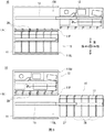
As shown in the appearance in FIG. 1, the
筐体2は、その前側に顧客が対峙した状態で紙幣の投入やタッチパネルによる操作等をしやすい箇所に顧客応対部3が設けられている。顧客応対部3は、カード入出口4、入出金口5、操作表示部6、テンキー7、及びレシート発行口8が設けられており、顧客との間で現金や通帳等を直接やり取りすると共に、取引に関する情報の通知や操作指示の受付を行うようになっている。
The
カード入出口4は、キャッシュカード等の各種カードが挿入または排出される部分である。カード入出口4の筐体内側には、各種カードに磁気記録された口座番号等の読み取りを行うカード処理部(図示せず)が設けられている。入出金口5は、顧客により入金する紙幣が投入されると共に、顧客へ出金する紙幣が排出される部分である。また入出金口5は、シャッタを駆動することにより開放又は閉塞するようになっている。
The card inlet /
操作表示部6は、取引に際して操作画面を表示するLCD(Liquid Crystal Display)と、取引の種類の選択、暗証番号や取引金額等を入力するタッチセンサとが一体化されたタッチパネルとなっている。テンキー7は、「0」〜「9」の数字等の入力を受け付ける物理キーであり、暗証番号や取引金額等の入力操作時に用いられる。レシート発行口8は、取引処理の終了時に取引内容等を印字したレシートを発行する部分である。因みにレシート発行口8の奥側には、レシートに取引内容等を印字するレシート処理部(図示せず)が設けられている。 The operation display unit 6 is a touch panel in which an LCD (Liquid Crystal Display) that displays an operation screen at the time of a transaction and a touch sensor that selects a transaction type and inputs a personal identification number, a transaction amount, and the like are integrated. The numeric keypad 7 is a physical key that accepts inputs such as numbers "0" to "9", and is used at the time of input operations such as a personal identification number and a transaction amount. The receipt issuing port 8 is a portion that issues a receipt on which transaction details and the like are printed at the end of transaction processing. Incidentally, a receipt processing unit (not shown) for printing transaction details and the like on the receipt is provided on the back side of the receipt issuing port 8.
以下では、現金自動預払機1のうち顧客が対峙する側を前側とし、その反対を後側とし、当該前側に対峙した顧客から見て左及び右をそれぞれ左側及び右側とし、さらに上側及び下側を定義して説明する。
In the following, the side of the
筐体2内には、現金自動預払機1全体を統括制御する主制御部9や、紙幣に関する種々の処理を行う紙幣入出金機10等が設けられている。主制御部9は、図示しないCPU(Central Processing Unit)を中心に構成されており、図示しないROM(Read Only Memory)やフラッシュメモリ等から所定のプログラムを読み出して実行することにより、入金処理や出金処理等の種々の処理を行う。また主制御部9は、内部にRAM(Random Access Memory)、ハードディスクドライブやフラッシュメモリ等でなる記憶部を有しており、この記憶部に種々の情報を記憶させる。
Inside the
紙幣入出金機10は、図2に側面図を示すように、中空の直方体状に構成された筐体11の内部に、媒体としての紙幣に関する種々の処理を行う複数の部分が組み込まれている。筐体11は、前側が開放されると共に、上下方向のほぼ中央に設けられた仕切部11Pにより、その内部が上側の上部空間11SUと下側の下部空間11SLとに仕切られている。上部空間11SU及び下部空間11SLには、それぞれ上部ユニット12及び下部ユニット15が収納されている。
As shown in the side view of FIG. 2, the bill deposit /
上部ユニット12には、全体を統括制御する紙幣制御部21、顧客との間で紙幣を授受する入出金部22、紙幣を各部へ搬送する搬送部23、紙幣を鑑別する鑑別部24及び紙幣を一時的に収納する一時保留部25が設けられている。
The
紙幣制御部21は、主制御部9と同様、図示しないCPUを中心に構成されており、図示しないROMやフラッシュメモリ等から所定のプログラムを読み出して実行することにより、紙幣の搬送先を決定する処理や各部の動作を制御する処理等、種々の処理を行う。また紙幣制御部21は、内部にRAM及びフラッシュメモリ等でなる記憶部を有しており、この記憶部に種々の情報を記憶させる。
Like the
入出金部22は、上部ユニット12内における前上部に位置しており、顧客から受け取った紙幣を1枚ずつに分離して搬送部23に引き渡し、また搬送部23から搬送されてきた紙幣を集積して利用者に受け取らせる。搬送部23は、紙幣を案内する搬送ガイドや多数の回転するローラ、或いは走行するベルト等が適宜配置されることにより、紙幣を搬送するための搬送路(図中に実線で示す)を形成している。この搬送部23は、各ローラを適宜回転させ、また各ベルトを適宜走行させることにより、搬送路に沿って紙幣を搬送する。また搬送部23は、紙幣の長辺を進行方向の先端及び末端に位置させ、当該紙幣を短辺に沿った方向に搬送する。
The deposit /
鑑別部24は、紙幣の搬送路に沿って配置されており、内部に組み込まれた複数種類のセンサにより、搬送される紙幣の金種、真偽、正損(損傷しているか否か)等を認識し、その認識結果を紙幣制御部21へ送出する。一時保留部25は、いわゆるテープエスクロ方式を採用しており、円筒状のドラムの周側面に紙幣をテープと共に巻き付けることで当該紙幣を収納し、またこの周側面から当該テープを引き剥がすことで紙幣を繰り出す。
The
下部ユニット15には、紙幣を収納する複数の紙幣収納庫26及びリジェクト収納庫27が設けられている。各紙幣収納庫26は、何れも同様に構成されており、内部に紙幣を集積して収納する空間を有している。この紙幣収納庫26は、鑑別部24及び紙幣制御部21により損傷の程度が小さく再利用が可能であると判断された紙幣が、その金種に応じて搬送部23により搬送されてくると、当該紙幣を内部に集積して収納する。また紙幣収納庫26は、紙幣制御部21から紙幣を繰り出す指示を受け付けると、集積している紙幣を1枚ずつに分離して繰り出し、搬送部23へ引き渡す。
The
リジェクト収納庫27は、共に内部に紙幣を集積して収納する空間を有している。このリジェクト収納庫27は、鑑別部24及び紙幣制御部21により損傷の程度が大きく再利用すべきで無いと判断された紙幣(いわゆるリジェクト紙幣)が搬送部23により搬送されてくると、当該紙幣を内部に収納する。
The
さらに筐体11における上部ユニット12及び下部ユニット15の間には、前後方向に沿って複数の受渡部28が配置されている。受渡部28は、紙幣を案内する受渡ガイド(詳しくは後述する)を有しており、搬送部23と紙幣収納庫26又はリジェクト収納庫27との間で紙幣を受け渡す場合に、両者の間で当該紙幣を仲介するように案内する。
Further, a plurality of
例えば顧客が現金自動預払機1との間で入金取引を行う場合、紙幣制御部21は、主制御部9等と連携しながら、操作表示部6を介して所定の操作入力を受け付けた後、入出金口5(図1)のシャッタを開いて入出金部22内へ紙幣を投入させる。入出金部22は、紙幣が投入されると、入出金口5のシャッタを閉じてから紙幣を1枚ずつに分離して搬送部23へ引き渡す。搬送部23は、受け取った紙幣を搬送すると共に鑑別部24により鑑別させ、得られた鑑別結果を紙幣制御部21へ通知する。これに応じて紙幣制御部21は、各紙幣の搬送先を決定する。
For example, when a customer makes a deposit transaction with an
このとき搬送部23は、鑑別部24において正常と鑑別された紙幣(いわゆる正券)を一時保留部25へ搬送して一時的に保留させる一方、取引すべきでないと鑑別された紙幣(いわゆる損券や偽券等)を入出金部22へ搬送して顧客に返却する。
At this time, the
その後紙幣制御部21は、操作表示部6(図1)を介して顧客に入金金額を確定させ、一時保留部25に保留している紙幣を鑑別部24へ搬送させてその金種及び損傷の程度等を鑑別させ、その鑑別結果を取得する。続いて紙幣制御部21は、紙幣の損傷の程度が大きければ、これを再利用すべきでないリジェクト紙幣として、受渡部28を介してリジェクト収納庫27へ搬送して収納させる。また紙幣制御部21は、紙幣の損傷の程度が小さければ、これを再利用すべき紙幣とし、受渡部28を介してその金種に応じた紙幣収納庫26へ搬送して収納させる。
After that, the
一方、例えば顧客が現金自動預払機1との間で出金取引を行う場合、紙幣制御部21は、主制御部9等と連携しながら、操作表示部6(図1)を介して所定の操作入力を受け付けた後、出金すべき金額に応じた紙幣を紙幣収納庫26から繰り出させる。続いて紙幣制御部21は、受渡部28を介してこの紙幣を搬送部23に引き渡し、当該搬送部23により鑑別部24へ搬送して鑑別させた上で入出金部22へ搬送し、入出金口5(図1)のシャッタを開いてこの紙幣を顧客に取り出させる。
On the other hand, for example, when a customer makes a withdrawal transaction with an
ところで現金自動預払機1の筐体2は、前側が開閉可能な扉となっており、この扉が開放されると、外部から紙幣入出金機10へのアクセスが可能となる。また紙幣入出金機10の筐体11は、上述した上部ユニット12及び下部ユニット15がスライドレール13及び16を介してそれぞれ取り付けられている。
By the way, the
このため紙幣入出金機10は、筐体2の扉が開放された状態で、スライドレール13を伸縮させながら上部ユニット12を前後方向へ移動させることにより、図2に示したように、当該上部ユニット12を筐体11の上部空間11SU内に収納した状態と、図3(A)に示すように、筐体11の前側に引き出した状態とに遷移させることができる。
Therefore, the banknote deposit /
これと同様に紙幣入出金機10は、スライドレール16を伸縮させながら下部ユニット15を前後方向へ移動させることにより、図2に示したように、当該下部ユニット15を筐体11の下部空間11SL内に収納した状態と、図3(B)に示すように、筐体11の前側に引き出した状態とに遷移させることができる。
Similarly, in the bill deposit / withdrawing
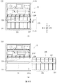
また下部ユニット15は、図4(B)に示すように、スライドレール16に取り付けられた下部フレーム17に、前後方向に沿って複数のスロット17Sが並んで配置されている。各スロット17Sは、上下方向に貫通した長方形状の孔となっており、それぞれの左右両側に紙幣収納庫26又はリジェクト収納庫27を支持する部分が形成されている。
Further, as shown in FIG. 4B, the
一方、紙幣収納庫26は、図4(A)に示すように、全体として上下方向に長い直方体状に形成されているものの、上側部分における左右方向の長さが下側部分よりも延長されることにより、前後方向から見て英文字の「T」のような形状に構成されている。因みにリジェクト収納庫27は、紙幣収納庫26と同様の外観を有している。
On the other hand, as shown in FIG. 4A, the
このため下部ユニット15では、筐体11の前方に下部フレーム17が引き出された状態で、各スロット17Sの上側から紙幣収納庫26が下方へ降ろされることにより、図4(C)に示すように、当該スロット17Sに紙幣収納庫26を装填させることができる。
Therefore, in the
また下部ユニット15では、紙幣収納庫26が装填されている下部フレーム17が筐体11の前方に引き出された状態で、当該紙幣収納庫26が上方へ持ち上げられることにより、各スロット17Sから当該紙幣収納庫26を離脱させることができる。因みに下部ユニット15では、リジェクト収納庫27も紙幣収納庫26と同様に、下部フレーム17のスロット17Sに対し着脱される。以下では、筐体11に対し下部フレーム17が移動する方向である前後方向を着脱方向とも呼ぶ。
Further, in the
さらに紙幣収納庫26は、下部フレーム17に装填され、且つ当該下部フレーム17が筐体11内に収納された場合(図2)、その上面を筐体11の仕切部11Pに設けられた受渡部28と対向させ、当該受渡部28との間で紙幣を相互に受け渡す位置に配置される。以下では、その上面を受渡部28と対向させ、両者の間で紙幣を受け渡し得るような紙幣収納庫26の位置を、対向位置と呼ぶ。また、紙幣収納庫26と受渡部28との間で紙幣を受け渡すときに当該紙幣を進行させる方向である上下方向を、搬送方向とも呼ぶ。
Further, when the
このように紙幣入出金機10は、下部フレーム17の各スロット17Sに紙幣収納庫26がそれぞれ装填され、当該下部フレーム17が筐体11内に収納された場合、各紙幣収納庫26をそれぞれ対向位置に配置し(図2)、筐体11の各受渡部28との間で紙幣を受け渡すことができる。
In this way, in the bill deposit /
[1−2.収納庫案内部及び受渡部の構成]
次に、紙幣収納庫26及び受渡部28の構成、並びにそれぞれに設けられた搬送ガイド同士の位置合わせについて説明する。
[1-2. Configuration of storage information section and delivery section]
Next, the configuration of the
[1−2−1.収納庫案内部の構成]
図4(A)に斜視図を示すと共に図5に部分的な三面図を示すように、紙幣収納庫26の収納庫筐体26Cにおける上側部分には、受渡部28との間で搬送される紙幣を案内する収納庫案内部30が形成されている。この収納庫案内部30には、前側に配置された収納庫前搬送ガイド32と、後側に配置された収納庫後搬送ガイド33とが設けられている。
[1-2-1. Configuration of storage information section]
As shown in FIG. 4 (A) as a perspective view and in FIG. 5 as a partial three-view view, the
収納庫前搬送ガイド32及び収納庫後搬送ガイド33の間には、所定の間隔(例えば5[mm])でなる搬送空間34が形成されている。この搬送空間34は、紙幣の紙面を前後方向に向けて、上下方向に沿って搬送する搬送路となっている。説明の都合上、以下では、収納庫前搬送ガイド32及び収納庫後搬送ガイド33をまとめて収納庫搬送ガイド群31とも呼ぶ。
A
収納庫後搬送ガイド33は、前面が平坦に形成された本体部41の上端に爪部42が設けられている。爪部42には、左右方向に沿って複数の爪体43が離散的に、すなわち左右方向に所定の間隔でなる隙間44を形成しながら配置されている。因みに爪部42には、左右方向の長さが異なる複数種類の爪体43が、所定の順序で配置されている。
The
第2爪体としての各爪体43は、概ね小さな直方体状に形成されており、それぞれの前面及び上面の位置を互いに揃えている。また各爪体43の前面は、本体部41の前面と連続している。さらに爪体43における前上側部分は、前面と上面との接合部分の近傍が斜めに切り落とされたような形状となっており、前斜め上方向を向いた傾斜面が形成されている。
Each
説明の都合上、以下では、複数の爪体43が整列されている左右方向を、幅方向とも呼ぶ。この幅方向(左右方向)は、上述した着脱方向(前後方向)及び搬送方向(上下方向)の何れとも交差する方向となっている。
For convenience of explanation, in the following, the left-right direction in which a plurality of
収納庫前搬送ガイド32は、収納庫後搬送ガイド33とほぼ前後対称に構成されており、本体部41の上端に爪部42が形成されている。この爪部42には、収納庫後搬送ガイド33と同様、複数の爪体43が左右方向に沿って離散的に配置されている。左右方向に隣接する爪体43同士の間には、隙間44が形成されている。すなわち収納庫前搬送ガイド32及び収納庫後搬送ガイド33は、左右方向及び上下方向に関し、互いの各爪体43の位置及び大きさを揃えている。以下では、収納庫後搬送ガイド33の前面及び収納庫前搬送ガイド32の後面を、それぞれガイド面とも呼ぶ。
The storage
さらに、紙幣収納庫26の収納庫案内部30には、収納庫搬送ガイド群31の右側、すなわち収納庫搬送ガイド群31の前側及び後側から外れた位置に、溝部36が形成されている。溝部36は、前後方向に沿った直線状に形成されており、互いに平行な左案内側面37及び右案内側面38によりほぼ一定の溝幅(長さL2)を維持している。また溝部36の深さ、すなわち紙幣収納庫26の上面から底面までの長さは、収納庫後搬送ガイド33における爪体43の高さ、若しくは隣接する爪体43同士の間に形成された隙間部分のよりもやや大きくなっている。
Further, in the
このように紙幣収納庫26の収納庫案内部30には、収納庫前搬送ガイド32及び収納庫後搬送ガイド33の上端に、左右方向に沿って爪体43が離散的に配置された爪部42が形成されており、且つ収納庫搬送ガイド群31の右側に、前後方向に沿った溝部36が形成されている。
In this way, in the
因みにリジェクト収納庫27の上部には、紙幣収納庫26と同様の収納庫案内部30が形成されており、紙幣収納庫26の場合と同様、収納庫搬送ガイド群31を有すると共に溝部36が形成されている。
Incidentally, a
[1−2−2.受渡部の構成]
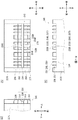
受渡部28は、図6に三面図を示すように、筐体11における仕切部11Pの一部でなる受渡フレーム50を中心に構成されている。受渡フレーム50には、上下方向に貫通し左右方向に長い角孔でなる孔部50Hが形成されている。孔部50H内における中央よりも前寄り及び後寄りとなる箇所には、受渡部前搬送ガイド52及び受渡部後搬送ガイド53が設けられている。説明の都合上、以下では、受渡部前搬送ガイド52及び受渡部後搬送ガイド53をまとめて受渡部搬送ガイド群51とも呼ぶ。
[1-2-2. Delivery section configuration]
As shown in the three views in FIG. 6, the
また受渡部28は、受渡部前搬送ガイド52及び受渡部後搬送ガイド53の間に、所定の間隔(例えば5[mm])でなる搬送空間54を形成している。この搬送空間54は、紙幣収納庫26の搬送空間34と同様、紙幣の紙面を前後方向に向け、上下方向に沿って搬送する搬送路となっている。
Further, the
受渡部後搬送ガイド53は、全体として前後方向に薄く上下方向に比較的短く左右方向に長い板状に形成されている。この受渡部後搬送ガイド53は、左右の両端部において、回動軸55を介して受渡フレーム50に取り付けられている。このため受渡部後搬送ガイド53は、受渡フレーム50に対し回動軸55を中心として回動することができる。
The post-delivery
受渡部後搬送ガイド53は、前後方向に薄く、上下方向に短く、左右方向に長い直方体状でなる本体部61を中心に構成されている。本体部61の下端には、爪部62が形成されている。この爪部62には、左右方向に沿って複数の爪体63が離散的に配置されている。各爪体63は、概ね小さな直方体状に形成されており、それぞれの前面及び下面の位置を互いに揃えている。左右方向に隣接する爪体63同士の間には、隙間64が形成されている。
The post-delivery
第1爪体としての各爪体63の左右方向に関する位置及び長さは、紙幣収納庫26の収納庫後搬送ガイド33における各爪体43と相補的に定められている。すなわち、受渡部後搬送ガイド53の爪部62における各爪体63の左右方向に関する位置及び長さは、収納庫後搬送ガイド33の各隙間44とそれぞれ対応している。また、受渡部後搬送ガイド53における各隙間64の左右方向に関する位置及び長さは、収納庫後搬送ガイド33における爪部42の各爪体43とそれぞれ対応している。
The position and length of each
受渡部前搬送ガイド52は、受渡部後搬送ガイド53とほぼ前後対称に構成されており、本体部61の下端に爪部62が形成されている。この爪部62には、受渡部後搬送ガイド53と同様、左右方向に関し、紙幣収納庫26の収納庫前搬送ガイド32における各爪体43と相補的な位置及び長さとなるように、複数の爪体63が左右方向に沿って離散的に配置されている。以下では、受渡部後搬送ガイド53の前面及び受渡部前搬送ガイド52の後面を、それぞれガイド面とも呼ぶ。
The delivery section
また受渡部前搬送ガイド52及び受渡部後搬送ガイド53それぞれにおける本体部61の上端には、爪部62と上下対称に構成された爪部66が設けられている。この爪部66には、各爪体63とそれぞれ上下対称な形状でなる複数の爪体67が設けられている。
Further, a
さらに、受渡部28における受渡部搬送ガイド群51の右側には、受渡フレーム50の下面に、位置規定部70が設けられている。位置規定部70は、支柱部71及び円板部72により構成されている。回転支持体としての支柱部71は、上下方向に沿った細い円柱状でなり、受渡フレーム50の下面から下方向へ向けて立設されている。支柱部71における上下方向の長さは、紙幣収納庫26における溝部36の深さと同等以下となっている。
Further, on the right side of the delivery section
円板体としての円板部72は、中心軸を上下方向に向けた円板状に形成されており、厚さ(すなわち上下方向の長さ)が支柱部71よりも十分に短くなっている。また円板部72の直径を表す長さL1は、溝部36の溝幅である長さL2よりも差分値ΔL12だけ短くなっている。また円板部72における中心近傍には、支柱部71の外径よりも僅かに大きい内径でなり上下方向に貫通する丸孔が穿設されている。
The
円板部72は、この丸孔に支柱部71が挿通されており、その上下に図示しない抜止部材が取り付けられることにより、当該支柱部71に対し、上下方向へ移動することなく自在に回転し得る。換言すれば、位置規定部70の円板部72は、いわゆるローラと同様に構成されている。
The
ところで筐体11には、図2に示したように、上部空間11SUと下部空間11SLとを上下に仕切る仕切部11Pに、複数の受渡部28が前後方向に沿って離散的に設けられている。このため筐体11における仕切部11Pの下面、すなわち下部空間11SLの天井面には、右側に、複数の位置規定部70が前後方向に沿って離散的に設けられている。
By the way, as shown in FIG. 2, the
このように受渡部28は、受渡部前搬送ガイド52及び受渡部後搬送ガイド53の下端に、左右方向に沿って爪体63が離散的に配置された爪部62がそれぞれ形成されており、且つ受渡部搬送ガイド群51の右側における受渡フレーム50の下面に、位置規定部70が設けられている。
As described above, in the
[1−2−3.搬送ガイド同士の位置合わせ]
上述したように、紙幣入出金機10は、下部フレーム17の各スロット17S(図4)に紙幣収納庫26及びリジェクト収納庫27が装填され、当該下部フレーム17が筐体11内に収納されることにより、紙幣収納庫26及びリジェクト収納庫27を対向位置に配置することができる。
[1-2-3. Alignment of transport guides]
As described above, in the bill deposit /
このとき紙幣収納庫26(図4(A))は、まず右側に突出した部分の下面に設けられた位置決め孔(図示せず)に対し、下部フレーム17の各スロット17Sに設けられた位置決めピン17P(図4(B))を陥入させることにより、当該下部フレーム17に対する前後方向、左右方向及び上下方向の位置が定められる。これにより下部フレーム17の各スロット17Sに装填された紙幣収納庫26は、上下方向及び左右方向の位置が互いに揃えられ、前後方向に沿って整列された状態となる。
At this time, the bill storage 26 (FIG. 4 (A)) first has a positioning pin provided in each slot 17S of the
下部フレーム17の各スロット17Sに装填された各紙幣収納庫26及びリジェクト収納庫27の上面には、上述したように収納庫案内部30がそれぞれ設けられている。このため各収納庫案内部30に形成されたそれぞれの溝部36は、各紙幣収納庫26の位置に応じて、前後方向に沿って一直線状に整列された状態となり、前後方向に沿った1本の長い溝を形成している(図4(C))。
As described above, storage guides 30 are provided on the upper surfaces of the
一方、筐体11には、上述したように、仕切部11Pの下面における右側に、複数の位置規定部70が前後方向に沿って離散的に設けられている。このため下部フレーム17は、筐体11の前方に引き出された状態(図3(B))から後方へ押し込まれると、スライドレール16の伸縮作用によりほぼ真後ろへ平行に移動し、下部空間11SL内へ収納されていく。
On the other hand, as described above, the
ここで、筐体11側に設けられている位置規定部70(図6)における円板部72の直径を表す長さL1は、各紙幣収納庫26及びリジェクト収納庫27の上面に設けられた収納庫案内部30(図5)の溝部36における溝幅を表す長さL2よりも、僅かに短い。このため各位置規定部70は、下部フレーム17の後方への移動に伴い、各紙幣収納庫26及びリジェクト収納庫27の溝部36内に順次入り込んでいく。
Here, the length L1 representing the diameter of the
これを他の観点から見ると、各紙幣収納庫26及びリジェクト収納庫27は、各位置規定部70が溝部36内に入り込むことで、当該位置規定部70により、受渡部28に対する収納庫搬送ガイド群31の左右方向の位置が精度良く定められる。このとき位置規定部70は、溝部36の左案内側面37又は右案内側面38に当接する可能性があるものの、円板部72が回転することにより、当該左案内側面37又は右案内側面38との間に摩擦を生じることなく、円滑に進行させることができる。
Looking at this from another point of view, in each
やがて下部フレーム17は、筐体11の下部空間11SL内に完全に収納されると(図2)、各紙幣収納庫26及びリジェクト収納庫27をそれぞれの対向位置に到達させる。このとき紙幣収納庫26は、図7に示すように、収納庫案内部30における収納庫前搬送ガイド32及び収納庫後搬送ガイド33の各爪部42と受渡部28における受渡部前搬送ガイド52及び受渡部後搬送ガイド53の各爪部62とを互いに噛み合わせる。因みに受渡部前搬送ガイド52及び受渡部後搬送ガイド53は、それぞれ回動軸55により適宜回動されて傾斜角度が調整される。
When the
これにより収納庫案内部30及び受渡部28は、収納庫後搬送ガイド33の前面と受渡部後搬送ガイド53の前面とによって、上下方向に沿って円滑に接続された、連続的な平面若しくは曲面を形成できる。また収納庫案内部30及び受渡部28は、収納庫前搬送ガイド32の後面と受渡部前搬送ガイド52の後面とによって、やはり上下方向に沿って円滑に接続された連続的な平面若しくは曲面を形成できる。
As a result, the
この結果、紙幣収納庫26及び受渡部28は、両者の間で紙幣を搬送すべき搬送路の前後それぞれにおいて、互いのガイド面同士を上下方向に円滑に接続することができ、上下方向に滑らかに接続された平面若しくは曲面を形成できる。これにより紙幣収納庫26及び受渡部28は、この搬送路に沿って紙幣を詰まらせることなく上下方向へ進行させること、すなわち円滑に受け渡すことができる。
As a result, the
ここで、図7の一部を拡大した図8に示すように、収納庫後搬送ガイド33の爪部42における、互いに隣接する爪体43J及び43Kの間に形成された隙間44Kと、この隙間44Kと対応する位置にある受渡部後搬送ガイド53の爪体63Kに着目する。
Here, as shown in FIG. 8 in which a part of FIG. 7 is enlarged, a
隙間44Kにおける左右方向の間隔である長さL4は、爪体63Kにおける左右方向の長さである長さL3よりも長い。このため爪体63Kは、紙幣収納庫26が正しく対向位置に配置されていれば、隙間44Kに入り込むことができる。
The length L4, which is the distance in the left-right direction in the
このとき爪体63Kは、左右両側に、爪体43J及び43Kとの隙間として左爪隙間G3L及び右爪隙間G3Rを形成する。左爪隙間G3L及び右爪隙間G3Rの加算値は、爪体63K及び隙間44Kの関係により、常に長さL4及び長さL3の差分である差分値ΔL34となる。この左爪隙間G3L及び右爪隙間G3Rは、受渡部後搬送ガイド53に対する収納庫後搬送ガイド33の相対的な左右方向の位置、すなわち筐体11に対する紙幣収納庫26の相対的な左右方向の位置に応じて、0から差分値ΔL34までの範囲内で、それぞれの値が増減する。
At this time, the
また、位置規定部70における円板部72の直径である長さL1は、溝部36の溝幅である長さL2よりも短い。このため位置規定部70が溝部36に入り込んでいる場合、位置規定部70の左右両側には、溝部36の左案内側面37及び右案内側面38との間に、それぞれ左ローラ隙間G1L及び右ローラ隙間G1Rが形成される。
Further, the length L1 which is the diameter of the
左ローラ隙間G1L及び右ローラ隙間G1Rの加算値は、常に長さL2及び長さL1の差分である差分値ΔL12となる。この左ローラ隙間G1L及び右ローラ隙間G1Rは、筐体11に対する紙幣収納庫26の相対的な左右方向の位置に応じて、0から差分値ΔL12までの範囲内で、それぞれの値が増減する。
The added value of the left roller gap G1L and the right roller gap G1R is always the difference value ΔL12 which is the difference between the length L2 and the length L1. The values of the left roller gap G1L and the right roller gap G1R increase or decrease within a range from 0 to the difference value ΔL12 according to the position of the
ここで収納庫案内部30及び受渡部28は、差分値ΔL34よりも差分値ΔL12の方が小さくなるよう、円板部72の直径である長さL1及び溝部36の溝幅である長さL2がそれぞれ適切に定められている。また収納庫案内部30及び受渡部28は、常に左爪隙間G3Lよりも左ローラ隙間G1Lの方が小さくなり、且つ常に右爪隙間G3Rよりも右ローラ隙間G1Rの方が小さくなるよう、位置規定部70の取付位置及び溝部36の形成位置がそれぞれ適切に定められている。
Here, the
このため収納庫案内部30及び受渡部28は、位置規定部70が溝部36内に入り込んでいる限り、左爪隙間G3L及び右爪隙間G3Rの値を何れも0よりも大きな値とすることになる。このことは、収納庫後搬送ガイド33の爪部42及び受渡部後搬送ガイド53の爪部62が、互いに左右方向に当接することなく、常に隙間を形成しながら噛み合うことを意味する。これを換言すれば、収納庫案内部30及び受渡部28は、位置規定部70及び溝部36により、左右方向に関し、収納庫後搬送ガイド33の爪部42及び受渡部後搬送ガイド53の爪部62の間で高精度な位置合わせができる。
For this reason, the
因みに収納庫案内部30及び受渡部28は、収納庫前搬送ガイド32及び受渡部前搬送ガイド52についても、これと同様に爪部42及び爪部62を左右方向に当接させることなく、隙間を形成しながら互いに噛み合わせることができる。
Incidentally, the
[1−3.効果等]
以上の構成において、第1の実施の形態による現金自動預払機1の紙幣入出金機10は、下部フレーム17の各スロット17Sに装填される各紙幣収納庫26及びリジェクト収納庫27の上部に収納庫案内部30を設けると共に、これらと対応する筐体11の仕切部11Pに複数の受渡部28を設けた。
[1-3. Effect, etc.]
In the above configuration, the banknote deposit /
収納庫案内部30は、搬送空間34を前後から挟むように位置する収納庫前搬送ガイド32及び収納庫後搬送ガイド33の上端に爪部42をそれぞれ形成すると共に、その右側に前後方向に沿った溝部36を設けた(図5)。一方、受渡部28は、搬送空間54を前後から挟むように位置する受渡部前搬送ガイド52及び受渡部後搬送ガイド53の下端に爪部62をそれぞれ形成すると共に、その右側に回転可能な円板部72を有する位置規定部70を設けた(図6)。
The
このため紙幣入出金機10は、下部フレーム17の各スロット17Sに各紙幣収納庫26及びリジェクト収納庫27が装填され、当該下部フレーム17が筐体11の下部空間11SL内に収納される場合に、位置規定部70を溝部36内へ導き、当該溝部36内を後方へ進行させる(図7及び図8)。
Therefore, in the bill deposit /
ここで、位置規定部70における円板部72の直径である長さL1は、溝部36における溝幅である長さL2よりも差分値ΔL12だけ短い。このため紙幣入出金機10は、位置規定部70の円板部72が溝部36の左案内側面37及び右案内側面38の間に位置することによって、受渡部28に対する収納庫案内部30の左右方向に関する位置を適切に定めることができる。
Here, the length L1 which is the diameter of the
また紙幣入出金機10は、位置規定部70及び溝部36における差分値ΔL12を、収納庫搬送ガイド群31における隙間44の長さL4と受渡部搬送ガイド群51における爪部62の爪体63の長さL3との差分値ΔL34よりも小さくした。さらに紙幣入出金機10は、常に左爪隙間G3Lよりも左ローラ隙間G1Lの方が小さくなり、且つ常に右爪隙間G3Rよりも右ローラ隙間G1Rの方が小さくなるよう、位置規定部70の取付位置及び溝部36の形成位置をそれぞれ適切に定めた(図8)。
Further, the bill deposit /
これにより紙幣入出金機10は、収納庫搬送ガイド群31の爪部42及び受渡部搬送ガイド群51の爪部62を、互いに左右方向に当接させることなく、常に隙間を形成しながら噛み合わせることができる。この結果、紙幣入出金機10では、紙幣収納庫26が下部フレーム17と共に前後方向へ移動する場合や対向位置に到達した場合に、収納庫搬送ガイド群31の爪部42及び受渡部搬送ガイド群51の爪部62が互いに衝突することによる破損を、確実に回避することができる。
As a result, the banknote deposit /
ところで紙幣入出金機10は、下部フレーム17が前後方向へ移動する際に筐体11に対し左右方向へ振れた場合、位置規定部70が溝部36の左案内側面37又は右案内側面38に当接して摺動する可能性がある。この点において位置規定部70は、上下方向に沿った支柱部71に対し、円板部72を自在に回転させ得るようにした(図6)。このため紙幣入出金機10は、円板部72が左案内側面37又は右案内側面38に当接した場合に回転させることができ、当該左案内側面37又は右案内側面38を摺動により損傷させることが無い。
By the way, in the bill deposit / withdrawing
また紙幣入出金機10では、下部フレーム17を筐体11の前側から下部空間11SL内へ収納するときに、最も後側に装填されるリジェクト収納庫27の収納庫案内部30において、溝部36の後側から位置規定部70が入ろうとする。ここで、例えば下部フレーム17が左方向へ振れていた場合、図9(A)に示すように、位置規定部70は、溝部36の後方においてその一部を左案内側面37の延長線よりも左側へはみ出させる場合がある。位置規定部70は、仮にその前面が平坦であった場合、この前面を収納庫案内部30における溝部36の後端周辺部分と当接させ、リジェクト収納庫27を含む下部フレーム17全体の後方への移動を妨げてしまう。
Further, in the bill deposit / withdrawing
この点において位置規定部70は、円板部72が円板状に形成されており、且つ支柱部71に対し自在に回転する(図6)。このため位置規定部70は、図9(A)に示したように、円板部72の中心軸が左案内側面37の延長線及び右案内側面38の延長線により挟まれる範囲内に位置していれば、左案内側面37の後端37Eに円板部72の周側面を当接させる。
At this point, in the
この状態で下部フレーム17及びリジェクト収納庫27が後方へ押し込まれた場合、位置規定部70は、円板部72を矢印R1方向へ回転させることにより、図9(B)に示すように、リジェクト収納庫27全体を左方向へ僅かに移動させながら、溝部36の内部へ入り込むことができる。すなわち位置規定部70は、収納庫案内部30が設けられたリジェクト収納庫27等における左右方向の位置を、収納庫搬送ガイド群31と受渡部搬送ガイド群51とを互いに対向させる対向位置に近づけるよう、修正することができる。
When the
さらに受渡部28では、受渡部搬送ガイド群51の右側に位置規定部70を設けた。これにより紙幣入出金機10は、左右方向の位置を合わせるべき収納庫搬送ガイド群31の爪部42及び受渡部搬送ガイド群51の爪部62から極めて近い箇所において、両者の位置を精度良く合わせることができる。
Further, in the
そのうえ位置規定部70は、支柱部71及び円板部72のような、極めて単純な構造である少数の部品により構成することができる。また収納庫案内部30の溝部36も、紙幣収納庫26等の上部に部品を追加することなく、例えば射出成型に用いる金型の形状を一部変更するだけで、容易に形成することができる。このため紙幣入出金機10では、特許文献1に記載されたような、位置決め用のピンを上下方向へ移動させるような複雑な機構を用いる場合と比較して、その構成を極めて簡素化することができ、部品点数や加工及び組立の工数を削減してコストの低廉化を図ることができる。
Moreover, the positioning
また紙幣入出金機10では、紙幣収納庫26等の上部に設けられる収納庫案内部30側に、周囲よりも一部分が凹んだ構造でなる溝部36を形成し、受渡部28側に周囲よりも下方へ突出した位置規定部70を設けた。これにより紙幣入出金機10では、仮に紙幣収納庫26等が下部フレーム17から取り外され単体で持ち運ばれる際に異物に衝突したとしても、周囲よりも凹んでいる溝部36がこの異物に衝突する可能性が極めて低く、変形や破損等のおそれが殆ど無い。
Further, in the bill deposit /
さらに紙幣入出金機10では、筐体11の仕切部11Pに複数の受渡部28を前後方向に沿って離散的に設け、各位置規定部70の上下方向及び左右方向の位置を揃えるように配置した。また下部フレーム17には、前後方向に沿って並んで形成された各スロット17Sに紙幣収納庫26等がそれぞれ装填される(図4(B))。このため各紙幣収納庫26等の収納庫案内部30には、互いに同じ位置に溝部36を設ければ良い。すなわち各紙幣収納庫26等については、下部フレーム17に装填される位置に拘わらず、互いの外形を同一に揃えることができ、製造コストを低廉に抑えることができる。
Further, in the bill deposit /
以上の構成によれば、第1の実施の形態による現金自動預払機1の紙幣入出金機10は、紙幣収納庫26等の上部に設けた収納庫案内部30において、収納庫搬送ガイド群31の右側に前後方向に沿った溝部36を設けた。また紙幣入出金機10は、筐体11に設けた受渡部28において、受渡部搬送ガイド群51の右側に位置規定部70を設けた。このため紙幣入出金機10は、紙幣収納庫26等が装填された下部フレーム17を筐体11内に収納するときに、位置規定部70を溝部36内に位置させることにより、受渡部28に対する収納庫案内部30の左右方向の位置を定めることができ、収納庫搬送ガイド群31の爪部42と受渡部搬送ガイド群51の爪部62とを互いに当接させることなく噛み合わせることができる。
According to the above configuration, the bill deposit /
[2.第2の実施の形態]
第2の実施の形態による現金自動預払機101(図1)は、第1の実施の形態による現金自動預払機1と比較して、紙幣入出金機10に代わる紙幣入出金機110を有する点において相違するものの、他の点については同様に構成されている。紙幣入出金機110(図2)は、紙幣入出金機10と比較して、筐体11、紙幣収納庫26、リジェクト収納庫27及び受渡部28に代わる筐体111、紙幣収納庫126、リジェクト収納庫127及び受渡部128を有する点において相違するものの、他の点については同様に構成されている。
[2. Second Embodiment]
The automatic teller machine 101 (FIG. 1) according to the second embodiment has a banknote deposit /
紙幣収納庫126は、紙幣収納庫26と比較して、収納庫筐体26Cに代わる収納庫筐体126Cの上部に、収納庫案内部30に代わる収納庫案内部130を有する点において相違するものの、他の点については同様に構成されている。リジェクト収納庫127も、紙幣収納庫126と同様に収納庫案内部130を有している。
Although the
収納庫案内部130は、図7と対応する図10に示すように、紙幣収納庫126等の上面における収納庫搬送ガイド群31の右側に、溝部36に代えて位置規定部170が設けられている。この位置規定部170は、第1の実施の形態における位置規定部70を上下方向に反転させた構成となっており、収納庫案内部130の上面よりも上方へ突出している。また位置規定部170は、位置規定部70と同様に構成されており、支柱部171に対し円板部172が自在に回転し得るようになっている。
As shown in FIG. 10 corresponding to FIG. 7, the
一方、受渡部128は、筐体111の一部でなる受渡フレーム150における受渡部搬送ガイド群51の右側に、位置規定部70に代えて溝部136が設けられている。この溝部136は、第1の実施の形態における溝部36を上下方向に反転させた構成となっており、図8と対応する図11に示すように、左案内側面137及び右案内側面138を有している。
On the other hand, the
紙幣入出金機110は、紙幣入出金機10と同様、常に左爪隙間G3Lよりも左ローラ隙間G1Lの方が小さくなり、且つ常に右爪隙間G3Rよりも右ローラ隙間G1Rの方が小さくなるよう、位置規定部170の取付位置及び溝部136の形成位置がそれぞれ適切に定められている。
Like the banknote deposit /
かかる構成により紙幣入出金機110は、受渡部128の溝部136と紙幣収納庫126等の収納庫案内部130における位置規定部170との組み合わせにより、第1の実施の形態と同様に、受渡部128に対する紙幣収納庫126等の左右方向に関する位置を定めることができる。これにより紙幣入出金機110は、第1の実施の形態と同様、収納庫搬送ガイド群31の爪部42及び受渡部搬送ガイド群51の爪部62を、互いに左右方向に当接させることなく、常に隙間を形成して衝突による破損を防止しながら噛み合わせることができる。
With this configuration, the banknote deposit /
その他の点においても、第2の実施の形態による紙幣入出金機110は、第1の実施の形態と同様の作用効果を奏し得る。
In other respects as well, the banknote deposit /
以上の構成によれば、第2の実施の形態による現金自動預払機101の紙幣入出金機110は、紙幣収納庫126等の上部に設けた収納庫案内部130において、収納庫搬送ガイド群31の右側に位置規定部170を設けた。また紙幣入出金機110は、筐体111に設けた受渡部128において、受渡部搬送ガイド群51の右側に前後方向に沿った溝部136を設けた。このため紙幣入出金機110は、紙幣収納庫126等が装填された下部フレーム17を筐体111内に収納するときに、位置規定部170を溝部136内に位置させることにより、受渡部128に対する収納庫案内部130の左右方向の位置を定めることができ、収納庫搬送ガイド群31の爪部42と受渡部搬送ガイド群51の爪部62とを互いに当接させることなく噛み合わせることができる。
According to the above configuration, the banknote deposit /
[3.第3の実施の形態]
第3の実施の形態による現金自動預払機201(図1)は、第1の実施の形態による現金自動預払機1と比較して、紙幣入出金機10に代わる紙幣入出金機210を有する点において相違するものの、他の点については同様に構成されている。
[3. Third Embodiment]
The automatic teller machine 201 (FIG. 1) according to the third embodiment has a banknote deposit /
[3−1.紙幣入出金機の構成]
図2と対応する図12(A)に示すように、紙幣入出金機210は、紙幣入出金機10と比較して、筐体11、紙幣収納庫26、リジェクト収納庫27及び受渡部28に代わる筐体211、紙幣収納庫226、リジェクト収納庫227並びに受渡部228及び受渡部229を有する点において相違するものの、他の点については同様に構成されている。
[3-1. Configuration of banknote deposit / withdrawal machine]
As shown in FIG. 12A corresponding to FIG. 2, the banknote deposit /
筐体211は、第1の実施の形態と同様、前側が開放されると共に、上下方向のほぼ中央に設けられた仕切部211Pにより、その内部が上側の上部空間211SUと下側の下部空間211SLとに仕切られている。上部空間211SU及び下部空間211SLには、それぞれ上部ユニット12及び下部ユニット215が収納されている。このうち上部ユニット12は第1の実施の形態とほぼ同様に構成されている。
Similar to the first embodiment, the
下部ユニット215には、5個の紙幣収納庫226と、該紙幣収納庫226の前側に位置する1個のリジェクト収納庫227とが設けられている。これに応じて筐体211の仕切部211Pには、前後方向に沿って5個の受渡部228及びその前側に1個の受渡部229が配置されている。受渡部228及び229は、何れも第1の実施の形態による受渡部28と同様、紙幣を案内する受渡ガイド(詳しくは後述する)を有しており、搬送部23と紙幣収納庫226又はリジェクト収納庫227との間で紙幣を受け渡す場合に、両者の間で当該紙幣を仲介するように案内する。
The
下部ユニット215は、筐体211に対してスライドレール16を介して取り付けられている。これにより紙幣入出金機210は、第1の実施の形態と同様、図12(A)に示したように、当該下部ユニット215を筐体211の下部空間211SL内に収納した状態と、図12(B)に示すように、筐体211の前側に引き出した状態とに遷移させることができる。
The
また下部ユニット215は、図13に示すように、スライドレール16に取り付けられた下部フレーム217に、前後方向に沿って5個のスロット17SA及び1個のスロット17SBが並んで配置されている。各スロット17SA及び17SBは、上下方向に貫通した長方形状の孔となっており、それぞれの後内側面の下方に紙幣収納庫226又はリジェクト収納庫227を支持する部分が設けられている。
Further, as shown in FIG. 13, in the
一方、紙幣収納庫226は、図4(A)と対応する図14(A)及び(B)に示すように、全体として上下方向に長い直方体状に形成されており、紙幣収納庫26と比較して左右方向に突出した部分が省略されている。また紙幣収納庫226の収納庫筐体226Cは、後面の左右両側における下端近傍に、前方へ向けて窪んだ部分がそれぞれ形成されている。さらに紙幣収納庫226における上面の後寄りには、紙幣収納庫案内部230が形成されている。
On the other hand, as shown in FIGS. 14 (A) and 14 (B) corresponding to FIG. 4 (A), the
リジェクト収納庫227は、図14(A)及び(B)と対応する図15(A)及び(B)に示すように、全体として上下方向に長く、紙幣収納庫226よりも前後方向に短い直方体状に形成されている。またリジェクト収納庫227の収納庫筐体227Cは、紙幣収納庫226と同様、後面の左右両側における下端近傍に、前方へ向けて窪んだ部分がそれぞれ形成されている。さらにリジェクト収納庫227における上面の前寄りには、リジェクト収納庫案内部240が形成されている。すなわち紙幣入出金機210では、紙幣収納庫226における紙幣収納庫案内部230の位置と、リジェクト収納庫227におけるリジェクト収納庫案内部240の位置とが、互いに前後反対となっている。
As shown in FIGS. 15 (A) and 15 (B) corresponding to FIGS. 14 (A) and 14 (B), the
[3−2.紙幣収納庫に関する案内部及び受渡部の構成]
次に、紙幣収納庫226の紙幣収納庫案内部230及び受渡部228の構成について説明する。
[3-2. Structure of information section and delivery section for banknote storage]
Next, the configuration of the bill
図5と対応する図16に示すように、紙幣収納庫案内部230には、紙幣収納庫226の中央に近い位置、すなわち内側に配置された収納庫内搬送ガイド232と、紙幣収納庫226の中央から離れた位置、すなわち外側に配置された収納庫外搬送ガイド233とが設けられている。
As shown in FIG. 16 corresponding to FIG. 5, the bill
説明の都合上、以下では、収納庫内搬送ガイド232及び収納庫外搬送ガイド233をまとめて収納庫搬送ガイド群231とも呼ぶ。また収納庫内搬送ガイド232及び収納庫外搬送ガイド233の間には、第1の実施の形態における搬送空間34と同様の搬送空間234が形成されている。
For convenience of explanation, in the following, the
収納庫外搬送ガイド233は、第1の実施の形態における収納庫後搬送ガイド33(図5)と同様に、複数の爪体が隙間を形成しながら離散的に配置されている。一方、収納庫内搬送ガイド232は、第1の実施の形態における収納庫前搬送ガイド32と比較して、概ね同様に構成され、複数の爪体が隙間を形成しながら離散的に配置されているものの、一部の形状が相違している。すなわち収納庫内搬送ガイド232は、収納庫外搬送ガイド233と前後対称形状にはなっていない。
Similar to the post-storage transport guide 33 (FIG. 5) in the first embodiment, the
また収納庫筐体226Cの上面には、収納庫内搬送ガイド232の前側に保護爪部236が設けられると共に、収納庫外搬送ガイド233の後側に保護爪部237が設けられている。この保護爪部236は、収納庫筐体226Cの上面から上方へ向けて立設された複数の爪体により構成されている。各爪体は、左右方向及び上下方向に関する大きさや配置が、収納庫内搬送ガイド232の各爪体と同様となっている。このため各爪体同士の間隔も、収納庫内搬送ガイド232と同様となっている。保護爪部237は、概ね保護爪部236と前後対称に構成されているものの、配置の制約等により、前後方向の長さが該保護爪部236よりも短くなっている。この保護爪部236及び237は、収納庫筐体226Cと同様に比較的強度が高い樹脂材料により構成されており、収納庫内搬送ガイド232及び収納庫外搬送ガイド233の各爪体を保護するようになっている。
Further, on the upper surface of the
一方、受渡部228は、図17(A)及び(B)に斜視図を示すと共に、図6と対応する図18に三面図を示すように、受渡フレーム250に各部品が取り付けられた構成となっている。受渡フレーム250の中央には、上下方向に貫通し左右方向に長い角孔でなる孔部250Hが形成されている。孔部250H内における中央よりも前寄り及び後寄りとなる箇所には、受渡部内搬送ガイド252及び受渡部外搬送ガイド253が設けられている。
On the other hand, the
説明の都合上、以下では、受渡部内搬送ガイド252及び受渡部外搬送ガイド253をまとめて受渡部搬送ガイド群251とも呼ぶ。
For convenience of explanation, in the following, the
受渡部内搬送ガイド252は、第1の実施の形態における受渡部前搬送ガイド52(図6)と同様に、収納庫内搬送ガイド232の各爪体及び隙間とそれぞれ相補的に形成された爪体及び隙間を有している。また受渡部外搬送ガイド253は、収納庫外搬送ガイド233の各爪体43及び隙間44とそれぞれ相補的に形成された爪体及び隙間を有している。ここで、収納庫内搬送ガイド232が収納庫外搬送ガイド233と前後対称形状になっていないため、受渡部外搬送ガイド253も受渡部内搬送ガイド252とは前後対称になっていない。
Similar to the delivery section front transfer guide 52 (FIG. 6) in the first embodiment, the delivery
受渡部外搬送ガイド253は、受渡部内搬送ガイド252との間に搬送空間254を形成した状態で、該受渡部内搬送ガイド252が取り付けられている。また受渡部外搬送ガイド253は、受渡フレーム250に対し回動軸255を中心として回動し得るようになっている。
The
この受渡部228は、受渡フレーム250における孔部250Hの位置を、筐体211の仕切部211Pに形成された仕切孔部211PHに合わせるようにして、該仕切部211Pの下面側に取り付けられている。
The
さらに、受渡部228の受渡フレーム250における下面の前側中央付近、すなわち
受渡部内搬送ガイド252における左右のほぼ中央に位置する中央爪体252Cの前側には、第1の実施の形態における位置規定部70と対応する位置規定部270が設けられている。
Further, on the front side of the central claw body 252C located near the center of the front side of the lower surface of the
位置規定部270は、第1の実施の形態における支柱部71及び円板部72とそれぞれ対応する支柱部271及び円板部272により構成されている。この円板部272の直径は、中央爪体252Cにおける左右方向の長さよりも僅かに長くなっている。すなわち円板部272の直径は、紙幣収納庫案内部230(図16)において収納庫内搬送ガイド232の中央に位置する中央隙間232D、及び収納庫外搬送ガイド233の中央に位置する中央隙間233Dにおける、左右方向の長さよりも僅かに短くなっている。すなわち円板部272の直径は、紙幣収納庫案内部230における保護爪部236の中央隙間236D及び保護爪部237の中央隙間237Dよりも、僅かに短くなっている。
The
因みに中央隙間232Dは、収納庫内搬送ガイド232の中央に位置する2個の爪体の互いに対向する側面である2箇所の中央案内側面232Sにより挟まれた隙間となっている。これと同様に、中央隙間233D、236D及び237Dは、それぞれ2箇所の中央案内側面233S、236S及び237Sにより挟まれた隙間となっている。
Incidentally, the central gap 232D is a gap sandwiched between the two central guide side surfaces 232S, which are the side surfaces of the two claw bodies located at the center of the
[3−3.リジェクト収納庫に関する案内部及び受渡部の構成]
次に、リジェクト収納庫227のリジェクト収納庫案内部240及び受渡部229の構成について説明する。
[3-3. Composition of information section and delivery section for reject storage]
Next, the configuration of the reject
図16と対応する図19に示すように、リジェクト収納庫案内部240には、リジェクト収納庫227の中央に近い位置、すなわち内側に配置された収納庫内搬送ガイド232と、リジェクト収納庫227の中央から離れた位置、すなわち外側に配置された収納庫外搬送ガイド233とが設けられている。すなわちリジェクト収納庫案内部240は、紙幣収納庫案内部230と比較して、収納庫内搬送ガイド232及び収納庫外搬送ガイド233が前後反対に設けられている。
As shown in FIG. 19, which corresponds to FIG. 16, the reject
また収納庫筐体227Cの上面には、紙幣収納庫226と前後反対になるように、収納庫外搬送ガイド233の前側に保護爪部237が設けられると共に、収納庫内搬送ガイド232の後側に保護爪部236が設けられている。
Further, on the upper surface of the
一方、受渡部229は、図17(A)及び(B)並びに図18とそれぞれ対応する図10(A)及び(B)並びに図21に示すように、受渡部228と比較して、受渡部内搬送ガイド252及び受渡部外搬送ガイド253が前後反対に設けられている。
On the other hand, as shown in FIGS. 10 (A) and 10 (B) and FIG. 21 corresponding to FIGS. 17 (A) and 17 (B) and 18 respectively, the
また受渡部229は、受渡部228と同様、受渡フレーム250における下面の前側中央付近に位置規定部270が設けられている。すなわち受渡部229では、受渡部228と異なり、受渡部外搬送ガイド253における左右のほぼ中央に位置する中央爪体253Cの前側に、この位置規定部270が設けられている。
Further, the
[3−4.搬送ガイド同士の位置合わせ]
上述したように、紙幣入出金機210は、下部フレーム217の各スロット217S(図13)に紙幣収納庫226及びリジェクト収納庫227が装填され、当該下部フレーム217が筐体211内に収納されることにより、紙幣収納庫226及びリジェクト収納庫227を対向位置に配置することができる。
[3-4. Alignment of transport guides]
As described above, in the banknote deposit /
このとき紙幣収納庫226(図14)及びリジェクト収納庫227(図15)は、後面における窪んだ部分の天井面に設けられた位置決め孔(図示せず)に対し、下部フレーム217の各スロット217Sに設けられた位置決めピン(図示せず)を陥入させる。これにより紙幣収納庫226及びリジェクト収納庫227は、下部フレーム217に対する前後方向、左右方向及び上下方向の位置が定められ、上下方向及び左右方向の位置が互いに揃えられ、前後方向に沿って整列された状態となる。
At this time, the banknote storage 226 (FIG. 14) and the reject storage 227 (FIG. 15) have each
下部フレーム217の各スロット217Sに装填された各紙幣収納庫226及びリジェクト収納庫227の上面では、紙幣収納庫案内部230及びリジェクト収納庫案内部240における各収納庫内搬送ガイド232及び各収納庫外搬送ガイド233(図16)が、左右方向に関して各爪部及び各隙間の位置を互いに揃えた状態となる。
On the upper surface of each
このとき各紙幣収納庫226及びリジェクト収納庫227では、図13(A)に一点鎖線で示したように、各収納庫内搬送ガイド232の中央隙間232D、各収納庫外搬送ガイド233の中央隙間233D、保護爪部236の中央隙間236D及び保護爪部237の中央隙間237Dにより、前後方向に沿って仮想的な1本の長い溝部を形成していると見なすことができる。
At this time, in each
このため紙幣入出金機210は、各中央隙間232D、233D、236D及び237Dと、各位置規定部270との組み合わせにより、第1の実施の形態と同様に、受渡部228及び229に対する紙幣収納庫226及びリジェクト収納庫227の左右方向に関する位置を定めることができる。
Therefore, the banknote deposit /
すなわち紙幣収納庫226は、下部空間211SL内で後方へ進行していく際に、まず後側の保護爪部237における中央案内側面237Sが、受渡部228等における受渡部内搬送ガイド252及び受渡部外搬送ガイド253の前側に位置する位置規定部270により案内され、左右方向の位置が精度良く定められる。
That is, when the
続いて紙幣収納庫226は、収納庫外搬送ガイド233の中央案内側面233S、収納庫内搬送ガイド232の中央案内側面232S、及び前側の保護爪部236における中央案内側面236Sが、位置規定部270により順次案内され、左右方向の位置が精度良く定められる。
Subsequently, in the
またリジェクト収納庫227も、紙幣収納庫226と同様に、各中央案内側面236S、232S、233S及び237Sが位置規定部270により順次案内され、それぞれ左右方向の位置が精度良く定められる。
Further, in the
これにより紙幣入出金機210は、紙幣収納庫226等の収納庫内搬送ガイド232及び収納庫外搬送ガイド233の各爪体と、受渡部228等の受渡部内搬送ガイド252及び受渡部外搬送ガイド253の各爪体とを、当接させることなく、衝突による破損を防止しながら噛み合わせることができる。
As a result, the banknote deposit /
特に紙幣入出金機210では、各紙幣収納庫226等の上面に設けられた保護爪部236の中央隙間236D及び保護爪部237の中央隙間237D、並びに収納庫内搬送ガイド232の中央隙間232D及び収納庫外搬送ガイド233の中央隙間233Dを、第1の実施の形態による溝部36(図5)と同様に機能させるようにした。このため紙幣入出金機210では、紙幣収納庫226及びリジェクト収納庫227において、第1の実施の形態における紙幣収納庫26(図4(A))のように上側部分における左右方向の長さを下側部分よりも延長する必要が無く、小型に構成することができる。
In particular, in the bill deposit /
ところで紙幣収納庫226では、紙幣の搬送時に静電気の発生を防止する観点から、収納庫内搬送ガイド232及び収納庫外搬送ガイド233が導電性を有する樹脂材料によって構成され、これに伴ってその強度がやや低くなっている。その一方で紙幣収納庫226では、保護爪部236及び237を、収納庫筐体226Cと同様に比較的強度が高い樹脂材料により構成している。
By the way, in the
そこで紙幣入出金機210では、紙幣収納庫226等の上面において、収納庫内搬送ガイド232及び収納庫外搬送ガイド233の前側及び後側に、保護爪部236及び237をそれぞれ配置した(図16)。このため紙幣入出金機210では、下部フレーム217の前後方向へのスライド時に、強度が低い収納庫内搬送ガイド232及び収納庫外搬送ガイド233よりも先に、強度が強い保護爪部236又は237に位置規定部270を当接させて位置決めすることができる。これにより紙幣入出金機210では、収納庫内搬送ガイド232及び収納庫外搬送ガイド233における各爪体の破損を防止することができる。
Therefore, in the banknote deposit /
ここで、図12(A)及び(B)と対応する図22(A)及び(B)に示すように、紙幣入出金機210と対応する紙幣入出金機310を構成する場合を想定する。この紙幣入出金機310は、紙幣入出金機210と反対に、筐体311に対して上部ユニット12及び下部ユニット315を後方へ引き出し得るようになっている。説明の都合上、以下では、下部ユニット215等を前方へ引き出す紙幣入出金機210を前面機とも呼び、下部ユニット315等を後方へ引き出す紙幣入出金機310を後面機とも呼ぶ。
Here, as shown in FIGS. 22 (A) and 22 (B) corresponding to FIGS. 12 (A) and 12 (B), it is assumed that the bill deposit /
ところで紙幣収納庫226では、搬送空間234の後側に収納庫外搬送ガイド233が配置されている(図16)。このため、この紙幣収納庫226と対応する受渡部では、該収納庫外搬送ガイド233と対応する受渡部外搬送ガイド253を搬送空間254の後側に位置させ、且つ位置規定部270を受渡部搬送ガイド群251よりも後側に配置する必要がある。そこで紙幣入出金機310では、紙幣収納庫226の上側に、これらの要件を満たす受渡部229(図20及び図21)が、紙幣入出金機210の場合とは前後反対に向けて取り付けられている。
By the way, in the
またリジェクト収納庫227では、搬送空間234の前側に収納庫外搬送ガイド233が配置されている(図19)。このため、このリジェクト収納庫227と対応する受渡部では、該収納庫外搬送ガイド233と対応する受渡部外搬送ガイド253を搬送空間254の前側に位置させ、且つ位置規定部270を受渡部搬送ガイド群251よりも前側に配置する必要がある。そこで紙幣入出金機310では、リジェクト収納庫227の上側に、これらの要件を満たす受渡部228(図17及び図18)が、紙幣入出金機210の場合とは前後反対に向けて取り付けられている。
Further, in the
このように紙幣入出金機310(図22)では、紙幣入出金機210(図12)の受渡部228及び229を、その取付位置及び取付方向を適宜変更することにより、流用することができる。すなわち紙幣入出金機210は、紙幣入出金機310との間で構成部品を共通化することができるので、製造コストの低廉化を図ることができる。
As described above, in the banknote deposit / withdrawal machine 310 (FIG. 22), the
その他の点においても、第3の実施の形態による紙幣入出金機210は、第1の実施の形態と同様の作用効果を奏し得る。
In other respects, the banknote deposit /
以上の構成によれば、第3の実施の形態による現金自動預払機201の紙幣入出金機210は、受渡部228及び229における受渡部搬送ガイド群251よりも前側に、位置規定部270を設けた。紙幣入出金機210は、紙幣収納庫226等が装填された下部フレーム217を筐体211内に収納するときに、保護爪部237の中央案内側面237S、収納庫外搬送ガイド233の中央案内側面233S、収納庫内搬送ガイド232の中央案内側面232S及び保護爪部236の中央案内側面236Sを位置規定部270により順次案内する。これにより紙幣入出金機210は、収納庫搬送ガイド群231の爪部と受渡部搬送ガイド群251の爪部とを互いに当接させることなく噛み合わせることができる。
According to the above configuration, the banknote deposit /
[4.他の実施の形態]
なお上述した第1の実施の形態においては、位置規定部70を支柱部71及び円板部72により構成し、且つ支柱部71に対し円板部72を自在に回転させる場合について述べた。しかしながら本発明はこれに限らず、例えば支柱部71に対し円板部72を固定しても良く、或いは位置規定部70を他の種々の形状としても良い。
[4. Other embodiments]
In the first embodiment described above, the case where the
例えば、位置規定部70を上下方向に沿った柱状とし、図23(A)、(B)、(C)及び(D)に示す位置規定部471、472、473及び474のように、上方から見た形状をそれぞれ円形、円弧の組合せ、六角形、又は八角形等とすることができる。このように位置規定部471等が回転しない場合、当該位置規定部471等及び溝部36における、互いに摺動する箇所の少なくとも一方に、摺動性を高める部材を貼り付けるようにしても良い。第2及び第3の実施の形態についても同様である。
For example, the
また上述した第1の実施の形態においては、溝部36における溝幅を一定とし、左案内側面37及び右案内側面38をそれぞれ平坦な平面とする場合について述べた。しかしながら本発明はこれに限らず、例えば図24(A)に示す溝部536のように、収納庫搬送ガイド群31の近傍のみ溝幅を溝部36と同様の長さL2とし、その他の部分における溝幅をこれよりも長くしても良い。これにより、下部フレーム17を前後方向へ移動させる際に左右方向へ振れたとしても、位置規定部70の円板部72が溝部536の左案内側面537や右案内側面538に当接する可能性を低減することができる。
Further, in the first embodiment described above, the case where the groove width in the
或いは、図24(B)に示す溝部636のように、左案内側面637及び右案内側面638における前後の頂点近傍を削除する等して、前後の端部近傍のみ、前端及び後端へ進むに連れて溝幅を長さL2から徐々に拡大させるようにしても良い。これにより、紙幣収納庫26等の左右方向への振れ幅が比較的大きい場合にも、位置規定部70を溝部636内へ導くことができ、当該紙幣収納庫26等の左右方向の位置を対向位置に近づけることができる。第2及び第3の実施の形態についても同様である。
Alternatively, as in the
さらに上述した第1の実施の形態においては、収納庫案内部30に溝部36を設け、位置規定部70を当該溝部36内に入り込ませることにより、収納庫案内部30の左右両方向に関する位置を規定する場合について述べた。しかしながら本発明はこれに限らず、例えば図25(A)に示すように、収納庫案内部730の右端近傍に溝部36の左案内側面37に代わる段差状の左案内側面737を設けることにより、紙幣収納庫26等の右方向への位置のみを定めるようにしても良い。
Further, in the first embodiment described above, the
或いは、図25(B)に示すように、収納庫案内部830の左右両端近傍に、それぞれ段差状でなる左案内側面837及び右案内側面838を設けると共に、位置規定部70を左右2箇所に設けることにより、紙幣収納庫26等の左右両方向への位置を規定しても良い。これにより、紙幣収納庫26における左右方向の長さが比較的短い場合など、場所の制約により十分な溝幅の溝部36を形成できない場合であっても、左右の少なくとも一方向に関して位置を規定することができる。第2及び第3の実施の形態についても同様である。
Alternatively, as shown in FIG. 25B, left guide side surfaces 837 and right guide side surfaces 838, which are stepped, are provided in the vicinity of the left and right ends of the
さらに上述した第1の実施の形態においては、差分値ΔL34よりも差分値ΔL12を小さくするよう、隙間44Kの幅(長さL4)、爪体63Kの幅(長さL3)、溝部36の溝幅(長さL2)及び円板部72の直径(長さL1)をそれぞれ定めることにより(図8)、爪部42及び爪部62の当接を回避する場合について述べた。しかしながら本発明はこれに限らず、例えば差分値ΔL34を差分値ΔL12と同等として、爪部42及び爪部62の当接を許容しても良い。第2及び第3の実施の形態についても同様である。
Further, in the first embodiment described above, the width of the
さらに上述した第3の実施の形態においては、各受渡部228及び229に位置規定部270を1個ずつ設ける場合について述べた(図17、図18、図20及び図21)。しかしながら本発明はこれに限らず、例えば各受渡部228及び229に位置規定部270を左右方向に2個以上ずつ並べるように設けても良い。この場合、各位置規定部270の位置及び大きさは、受渡部内搬送ガイド252等における各爪体に合わせれば良い。
Further, in the third embodiment described above, a case where one position-determining
或いは、例えば受渡部228において、受渡部内搬送ガイド252の前側に加えて、受渡部外搬送ガイド253の後側にも位置規定部270を配置しても良い。これにより、紙幣収納庫226等が筐体211内を後方へ進行する場合に加えて、前方へ進行するときにも、爪体同士の衝突を効果的に防止できる。またこの場合、受渡部229が受渡部228と同一の構成となるため、部品の共通化によるコストの低廉化を図ることもできる。
Alternatively, for example, in the
さらに上述した第3の実施の形態においては、紙幣収納庫226等の上面において、収納庫内搬送ガイド232及び収納庫外搬送ガイド233の前後に、保護爪部236及び237をそれぞれ設ける場合について述べた。また保護爪部236及び237の各爪体については、収納庫内搬送ガイド232及び収納庫外搬送ガイド233の各爪体と同等の形状とした。しかしながら本発明はこれに限らず、例えば保護爪部236及び237における一部の爪体を省略しても良い。この場合、少なくとも中央隙間236D及び237Dを形成する爪体を残すことが好ましい。また、保護爪部236及び237のうち少なくとも一方を省略しても良い。
Further, in the third embodiment described above, the case where the
さらに上述した第3の実施の形態においては、収納庫内搬送ガイド232及び収納庫外搬送ガイド233を前後非対称とし、これに応じて受渡部内搬送ガイド252及び受渡部外搬送ガイド253も前後非対称とする場合について述べた。しかしながら本発明はこれに限らず、例えば収納庫内搬送ガイド232及び収納庫外搬送ガイド233を前後対称とし、これに応じて受渡部内搬送ガイド252及び受渡部外搬送ガイド253も前後対称としても良い。この場合も、受渡部229が受渡部228と同一の構成となるため、部品の共通化によるコストの低廉化を図ることができる。
Further, in the third embodiment described above, the
さらに上述した第3の実施の形態においては、受渡部228等に位置規定部270を設け、これにより紙幣収納庫226側における収納庫内搬送ガイド232の中央隙間232D等を案内する場合について述べた。しかしながら本発明はこれに限らず、例えば第2の実施の形態(図10及び図11)と同様に、紙幣収納庫226側に位置規定部270を設け、これにより受渡部側の受渡部内搬送ガイド252等における爪体同士の隙間部分を案内するようにしても良い。
Further, in the third embodiment described above, a case has been described in which a
さらに上述した第1の実施の形態においては、筐体11の仕切部11Pに複数の受渡部28を前後方向に並べて配置し、各位置規定部70の上下方向及び左右方向の取付位置を揃える場合について述べた。しかしながら本発明はこれに限らず、例えば各位置規定部70の上下方向及び左右方向の取付位置を互いに相違させても良い。この場合、各紙幣収納庫26等の収納庫案内部30に形成する溝部36の溝幅や溝の深さ等を、互いに相違させれば良い。第2及び第3の実施の形態についても同様である。
Further, in the first embodiment described above, when a plurality of
さらに上述した第1の実施の形態においては、受渡部28において受渡フレーム50に対し回動軸55を介して受渡部前搬送ガイド52及び受渡部後搬送ガイド53を回動させる場合について述べた。しかしながら本発明はこれに限らず、たとえば受渡フレーム50に対し受渡部前搬送ガイド52及び受渡部後搬送ガイド53を上下方向や前後方向へ移動させるようにしても良く、或いは受渡フレーム50に対し受渡部前搬送ガイド52及び受渡部後搬送ガイド53を固定しても良い。第2及び第3の実施の形態についても同様である。
Further, in the first embodiment described above, the case where the
さらに上述した第1の実施の形態においては、筐体11に対し下部フレーム17を前後方向へ移動させるようにし、紙幣収納庫26等と受渡部28との間で紙面を前後方向に向けた紙幣を上下方向に沿って搬送する構成とした上で、溝部36及び位置規定部70により搬送ガイド同士の左右方向に関する位置を合わせる場合について述べた。しかしながら本発明はこれに限らず、下部フレーム17を移動させる方向、紙幣を搬送する方向及び搬送ガイド同士の位置を合わせる方向を、それぞれ種々の方向としても良い。この場合、要は下部フレーム17が移動する着脱方向に紙面を向けた状態で、この着脱方向と交差する搬送方向に紙幣を搬送して受け渡す構成とした上で、溝部36及び位置規定部70により、着脱方向及び搬送方向の何れとも交差する幅方向に関する互いの搬送ガイドの位置を合わせて、爪部42及び62を衝突させずに噛み合わせれば良い。第2及び第3の実施の形態についても同様である。
Further, in the first embodiment described above, the
さらに上述した第1の実施の形態においては、顧客との間で現金に関する取引を行う現金自動預払機1の紙幣入出金機10に本発明を適用する場合について述べた。しかしながら本発明はこれに限らず、例えば金融機関の窓口に設置され当該金融機関の職員が主に使用する紙幣処理装置(いわゆるテラーマシン)等、装置本体からスライドレールにより装填部を引き出した状態で収納庫を装填し又は取り外すような、種々の装置に適用しても良い。第2及び第3の実施の形態についても同様である。
Further, in the first embodiment described above, the case where the present invention is applied to the banknote deposit /
さらに上述した第1の実施の形態においては、紙幣収納庫26に媒体としての紙幣を収納する場合について述べた。しかしながら本発明はこれに限らず、例えば金券や証券、或いは入場券等の種々の媒体を収納する収納庫を、移動するフレームに対し着脱させる種々の装置に適用しても良い。媒体の形状としては、紙幣のような紙葉状に限らず、直方体状等の種々の形状であっても良い。第2及び第3の実施の形態についても同様である。
Further, in the first embodiment described above, a case where banknotes as a medium is stored in the
さらに本発明は、上述した各実施の形態及び他の実施の形態に限定されるものではない。すなわち本発明は、上述した各実施の形態と上述した他の実施の形態の一部又は全部を任意に組み合わせた実施の形態や、一部を抽出した実施の形態にもその適用範囲が及ぶものである。 Furthermore, the present invention is not limited to the above-described embodiments and other embodiments. That is, the scope of the present invention extends to an embodiment in which each of the above-described embodiments and a part or all of the above-mentioned other embodiments are arbitrarily combined, and an embodiment in which a part is extracted. Is.
さらに上述した第1の実施の形態においては、第1筐体としての受渡フレーム50と、第2筐体としての収納庫筐体26Cと、第1搬送ガイドとしての受渡部前搬送ガイド52及び受渡部後搬送ガイド53と、第2搬送ガイドとしての収納庫前搬送ガイド32及び収納庫後搬送ガイド33と、第1爪部としての爪部62と、第2爪部としての爪部42と、案内側面としての左案内側面37及び右案内側面38と、位置規定部としての位置規定部70とによって媒体搬送装置としての受渡部28及び収納庫案内部30を構成する場合について述べた。しかしながら本発明はこれに限らず、その他種々の構成でなる第1筐体と、第2筐体と、第1搬送ガイドと、第2搬送ガイドと、第1爪部と、第2爪部と、案内側面と、位置規定部とによって媒体搬送装置を構成しても良い。
Further, in the above-described first embodiment, the
さらに上述した第1の実施の形態においては、第1筐体としての筐体11と、第2筐体としての収納庫筐体26Cと、第1搬送ガイドとしての受渡部前搬送ガイド52及び受渡部後搬送ガイド53と、第2搬送ガイドとしての収納庫前搬送ガイド32及び収納庫後搬送ガイド33と、第1爪部としての爪部62と、第2爪部としての爪部42と、案内側面としての左案内側面37及び右案内側面38と、位置規定部としての位置規定部70とによって媒体取引装置としての現金自動預払機1を構成する場合について述べた。しかしながら本発明はこれに限らず、その他種々の構成でなる第1筐体と、第2筐体と、第1搬送ガイドと、第2搬送ガイドと、第1爪部と、第2爪部と、案内側面と、位置規定部とによって媒体取引装置を構成しても良い。
Further, in the first embodiment described above, the
本発明は、例えば現金自動預払機のように、紙幣等の媒体を収納する収納庫をフレームに対して着脱可能とし、且つこのフレームをスライドにより筐体内に収納させ、収納時に収納庫と筐体との間で媒体を受け渡すような種々の装置でも利用できる。 In the present invention, for example, like an automated teller machine, a storage compartment for storing a medium such as banknotes can be attached to and detached from a frame, and the frame can be stored in a housing by a slide. It can also be used in various devices that transfer media to and from.
1、101、201……現金自動預払機、10、110、210……紙幣入出金機、11、111、211……筐体、11P、211P……仕切部、11SL、211SL……下部空間、15、215……下部ユニット、16……スライドレール、17、217……下部フレーム、17P……位置決めピン、17S……スロット、21……紙幣制御部、23……搬送部、26、126、226……紙幣収納庫、26C、226C……収納庫筐体、27、127、227……リジェクト収納庫、28、128、228、229……受渡部、30、130……収納庫案内部、31、231……収納庫搬送ガイド群、32……収納庫前搬送ガイド、33……収納庫後搬送ガイド、34、234……搬送空間、36、136……溝部、37、137……左案内側面、38、138……右案内側面、41、61……本体部、42、62、66……爪部、43、63、67……爪体、44、64……隙間、50、150、250……受渡フレーム、50H、250H……孔部、51、251……受渡部搬送ガイド群、52……受渡部前搬送ガイド、53……受渡部後搬送ガイド、54、254……搬送空間、55、255……回動軸、70、170、270……位置規定部、71、171、271……支柱部、72、172、272……円板部、230……紙幣収納庫案内部、232……収納庫内搬送ガイド、233……収納庫外搬送ガイド、236、237……保護爪部、232D、233D、236D、237D……中央隙間、232S、233S、236S、237S……中央案内側面、240……リジェクト収納庫案内部、252……受渡部内搬送ガイド、253……受渡部外搬送ガイド、G1L……左ローラ隙間、G1R……右ローラ隙間、G3L……左爪隙間、G3R……右爪隙間。 1, 101, 201 ... Automatic teller machine, 10, 110, 210 ... Banknote deposit / withdrawal machine, 11, 111, 211 ... Housing, 11P, 211P ... Partition, 11SL, 211SL ... Lower space, 15, 215 ... Lower unit, 16 ... Slide rail, 17, 217 ... Lower frame, 17P ... Positioning pin, 17S ... Slot, 21 ... Banknote control unit, 23 ... Transport unit, 26, 126, 226 ... Banknote storage, 26C, 226C ... Storage housing, 27, 127, 227 ... Reject storage, 28, 128, 228, 229 ... Delivery section, 30, 130 ... Storage information section, 31, 231 ... Storage transport guide group, 32 ... Storage front transport guide, 33 ... Storage rear transport guide, 34, 234 ... Transport space, 36, 136 ... Groove, 37, 137 ... Left Guide side, 38, 138 ... Right guide side, 41, 61 ... Main body, 42, 62, 66 ... Claw, 43, 63, 67 ... Claw, 44, 64 ... Gap, 50, 150 , 250 …… Delivery frame, 50H, 250H …… Hole, 51, 251 …… Delivery guide transport guide group, 52 …… Delivery guide before delivery, 53 …… Transfer guide after delivery, 54, 254 …… Transport Space, 55, 255 ... Rotating shaft, 70, 170, 270 ... Positioning part, 71, 171, 271 ... Support part, 72, 172, 272 ... Disk part, 230 ... Banknote storage guide Department, 232 ... In-storage transport guide, 233 ... Out-of-storage transport guide, 236, 237 ... Protective claws, 232D, 233D, 236D, 237D ... Central gap, 232S, 233S, 236S, 237S ... Central guide side, 240 …… Reject storage guide, 252 …… Transfer guide inside the delivery section, 253 …… Transport guide outside the delivery section, G1L …… Left roller gap, G1R …… Right roller gap, G3L …… Left claw gap , G3R …… Right nail gap.
Claims (11)
着脱方向へ移動されることにより、前記第1筐体と対向する対向位置に配置され、又は当該対向位置から離脱される第2筐体と、
前記第1筐体に設けられ、前記対向位置に配置された前記第2筐体との間で、着脱方向と交差する搬送方向に沿って搬送される媒体を案内する第1搬送ガイドと、
前記第2筐体における、当該第2筐体が前記対向位置に配置された場合に前記第1搬送ガイドと対向する箇所に設けられ、当該第1搬送ガイドと共に前記媒体を案内する第2搬送ガイドと、
前記第1搬送ガイドにおける前記第2搬送ガイドと対向する箇所に、着脱方向及び搬送方向と交差する幅方向に沿って離散した箇所に、複数の第1爪体が前記第2搬送ガイドへ向けてそれぞれ立設された第1爪部と、
前記第2搬送ガイドにおける前記第1搬送ガイドと対向する箇所に、幅方向に沿って離散した箇所であって前記第1爪部の前記第1爪体とそれぞれ相補的な箇所に、複数の第2爪体が前記第1搬送ガイドへ向けてそれぞれ立設された第2爪部と、
前記第2筐体の前記第1筐体と対向する上面において、前記幅方向に前記第2搬送ガイドとは離れた位置に設けられ、前記着脱方向に沿って形成された案内側面を有する溝部と、
前記第1筐体の前記第2筐体と対向する下面において、前記幅方向に前記第1搬送ガイドとは離れた位置に設けられ、前記第2筐体を前記対向位置に配置する際に、前記溝部に入り込むことにより該溝部の前記案内側面に対する幅方向の位置を規定し、前記第1爪部及び前記第2爪部が互いに噛み合うようにする位置規定部と
を具えることを特徴とする媒体搬送装置。 With the first housing
A second housing that is arranged at a position facing the first housing or is separated from the facing position by being moved in the attachment / detachment direction.
A first transport guide provided in the first housing and guiding a medium to be transported along a transport direction intersecting the attachment / detachment direction between the second housing and the second housing arranged at the opposite positions.
In the second housing, when the second housing is arranged at the facing position, the second transport guide is provided at a position facing the first transport guide and guides the medium together with the first transport guide. When,
A plurality of first claws are directed toward the second transport guide at locations facing the second transport guide in the first transport guide, and at locations discrete along the attachment / detachment direction and the width direction intersecting the transport direction. The first claws that were erected respectively,
A plurality of positions of the second transport guide that are discrete along the width direction and that are complementary to the first claw body of the first claw portion are located at locations that face the first transport guide. The second claws, each of which has two claws erected toward the first transport guide,
The upper surface which faces the first housing of the second body, provided at a position separated from said second conveyance guide in the width direction, and a groove portion having a guide side is formed along the detachable direction ,
In the second housing facing the lower surface of the first housing is provided at a position away from said first conveyor guide in the width direction, when placing the second housing to the opposing position, It is characterized in that the position of the groove portion in the width direction with respect to the guide side surface is defined by entering the groove portion, and the position defining portion is provided so that the first claw portion and the second claw portion mesh with each other. Medium transfer device.
着脱方向へ移動されることにより、前記第1筐体と対向する対向位置に配置され、又は当該対向位置から離脱される第2筐体と、A second housing that is arranged at a position facing the first housing or is separated from the facing position by being moved in the attachment / detachment direction.
前記第1筐体に設けられ、前記対向位置に配置された前記第2筐体との間で、着脱方向と交差する搬送方向に沿って搬送される媒体を案内する第1搬送ガイドと、A first transport guide provided in the first housing and guiding a medium to be transported along a transport direction intersecting the attachment / detachment direction between the second housing and the second housing arranged at the opposite positions.
前記第2筐体における、当該第2筐体が前記対向位置に配置された場合に前記第1搬送ガイドと対向する箇所に設けられ、当該第1搬送ガイドと共に前記媒体を案内する第2搬送ガイドと、In the second housing, when the second housing is arranged at the facing position, the second transport guide is provided at a position facing the first transport guide and guides the medium together with the first transport guide. When,
前記第1搬送ガイドにおける前記第2搬送ガイドと対向する箇所に、着脱方向及び搬送方向と交差する幅方向に沿って離散した箇所に、複数の第1爪体が前記第2搬送ガイドへ向けてそれぞれ立設された第1爪部と、A plurality of first claws are directed toward the second transport guide at locations facing the second transport guide in the first transport guide, and at locations discrete along the attachment / detachment direction and the width direction intersecting the transport direction. The first claws that were erected respectively,
前記第2搬送ガイドにおける前記第1搬送ガイドと対向する箇所に、幅方向に沿って離散した箇所であって前記第1爪部の前記第1爪体とそれぞれ相補的な箇所に、複数の第2爪体が前記第1搬送ガイドへ向けてそれぞれ立設された第2爪部と、A plurality of positions of the second transport guide that are discrete along the width direction and that are complementary to the first claw body of the first claw portion are located at locations that face the first transport guide. The second claws, each of which has two claws erected toward the first transport guide,
前記第1筐体の前記第2筐体と対向する下面において、前記幅方向に前記第1搬送ガイドとは離れた位置に設けられ、着脱方向に沿って形成された案内側面を有する溝部と、On the lower surface of the first housing facing the second housing, a groove portion provided at a position separated from the first transport guide in the width direction and having a guide side surface formed along the attachment / detachment direction, and a groove portion.
前記第2筐体の前記第1筐体と対向する上面において、前記幅方向に前記第2搬送ガイドとは離れた位置に設けられ、前記第2筐体を前記対向位置に配置する際に、前記溝部に入り込むことにより該溝部の前記案内側面に対する幅方向の位置を規定し、前記第1爪部及び前記第2爪部が互いに噛み合うようにする位置規定部とOn the upper surface of the second housing facing the first housing, the second housing is provided at a position separated from the second transport guide in the width direction, and when the second housing is arranged at the facing position, A position defining portion that defines the position of the groove in the width direction with respect to the guide side surface by entering the groove, and causes the first claw portion and the second claw portion to mesh with each other.
を具えることを特徴とする媒体搬送装置。A medium transfer device characterized by being equipped with.
中心軸を搬送方向に沿わせた円板体と、
前記円板体の中心軸を中心として回転可能に支持する回転支持体と
を具え、
前記案内側面は、前記第2筐体が前記対向位置に配置された場合に、前記円板体の周側面により幅方向の位置が規定される
ことを特徴とする請求項1又は請求項2に記載の媒体搬送装置。 The position defining part is
A disk body with the central axis along the transport direction,
A rotary support that rotatably supports the disk body around the central axis is provided.
The guide side surface is according to claim 1 or 2 , wherein the position in the width direction is defined by the peripheral side surface of the disk body when the second housing is arranged at the facing position. The medium transport device according to the description.
ことを特徴とする請求項3に記載の媒体搬送装置。 When the second housing is arranged at the opposite position, the distance between the inner side surface forming the guide side surface of the groove portion in the width direction and the peripheral side surface of the disk body is the first one adjacent to each other. The medium transfer device according to claim 3 , wherein the distance between the first claw body of the claw portion and the second claw body of the second claw portion is narrower than each distance.
ことを特徴とする請求項1又は請求項2に記載の媒体搬送装置。 The position defining portion is provided with respect to the guide side surface so that when the second housing is arranged at the facing position, the first claw portion and the second claw portion mesh with each other while providing a gap in the width direction. The medium transfer device according to claim 1 or 2 , wherein the position in the width direction is specified.
着脱方向へ移動されることにより、前記第1筐体と対向する対向位置に配置され、又は当該対向位置から離脱される第2筐体と、
前記第1筐体に設けられ、前記対向位置に配置された前記第2筐体との間で、着脱方向と交差する搬送方向に沿って搬送される媒体を案内する第1搬送ガイドと、
前記第2筐体における、当該第2筐体が前記対向位置に配置された場合に前記第1搬送ガイドと対向する箇所に設けられ、当該第1搬送ガイドと共に前記媒体を案内する第2搬送ガイドと、
前記第1搬送ガイドにおける前記第2搬送ガイドと対向する箇所に、着脱方向及び搬送方向と交差する幅方向に沿って離散した箇所に、複数の第1爪体が前記第2搬送ガイドへ向けてそれぞれ立設された第1爪部と、
前記第2搬送ガイドにおける前記第1搬送ガイドと対向する箇所に、幅方向に沿って離散した箇所であって前記第1爪部の前記第1爪体とそれぞれ相補的な箇所に、複数の第2爪体が前記第1搬送ガイドへ向けてそれぞれ立設された第2爪部と、
前記第1筐体及び前記第2筐体の一方に設けられ、幅方向に面し、着脱方向に沿って形成された案内側面と、
前記第1筐体及び前記第2筐体の他方に設けられ、前記第2筐体が前記対向位置に配置された場合に、前記第1爪部及び前記第2爪部が互いに噛み合うように、前記案内側面に対する幅方向の位置を規定する位置規定部と
を具え、
前記位置規定部は、前記第1筐体及び前記第2筐体の他方において、前記第1搬送ガイドの前記第1爪体又は前記第2搬送ガイドの前記第2爪体の前記着脱方向側に設けられ、
前記案内側面は、前記第1筐体及び前記第2筐体の一方における、前記第1搬送ガイド又は前記第2搬送ガイドの着脱方向側に設けられた、前記第1爪部の前記第1爪体又は前記第2爪部の前記第2爪体と対応する形状に形成された保護爪部の、幅方向の側面である
ことを特徴とする媒体搬送装置。 With the first housing
A second housing that is arranged at a position facing the first housing or is separated from the facing position by being moved in the attachment / detachment direction.
A first transport guide provided in the first housing and guiding a medium to be transported along a transport direction intersecting the attachment / detachment direction between the second housing and the second housing arranged at the opposite positions.
In the second housing, when the second housing is arranged at the facing position, the second transport guide is provided at a position facing the first transport guide and guides the medium together with the first transport guide. When,
A plurality of first claws are directed toward the second transport guide at locations facing the second transport guide in the first transport guide, and at locations discrete along the attachment / detachment direction and the width direction intersecting the transport direction. The first claws that were erected respectively,
A plurality of positions of the second transport guide that are discrete along the width direction and that are complementary to the first claw body of the first claw portion are located at locations that face the first transport guide. The second claws, each of which has two claws erected toward the first transport guide,
A guide side surface provided on one of the first housing and the second housing, facing in the width direction, and formed along the attachment / detachment direction.
Provided on the other side of the first housing and the second housing, when the second housing is arranged at the opposite position, the first claw portion and the second claw portion mesh with each other. With the position defining part that defines the position in the width direction with respect to the guide side surface
With
The positioning portion is located on the other side of the first housing and the second housing on the attachment / detachment direction side of the first claw body of the first transport guide or the second claw body of the second transport guide. Provided,
The guide side surface is the first claw of the first claw portion provided on the attachment / detachment direction side of the first transport guide or the second transport guide in one of the first housing and the second housing. medium body conveying device you wherein the body or of the said protective claw portion formed in a shape corresponding to the second pawl member of the second claw portion, a side in the width direction.
着脱方向へ移動されることにより、前記第1筐体と対向する対向位置に配置され、又は当該対向位置から離脱される第2筐体と、
前記第1筐体に設けられ、前記対向位置に配置された前記第2筐体との間で、着脱方向と交差する搬送方向に沿って搬送される媒体を案内する第1搬送ガイドと、
前記第2筐体における、当該第2筐体が前記対向位置に配置された場合に前記第1搬送ガイドと対向する箇所に設けられ、当該第1搬送ガイドと共に前記媒体を案内する第2搬送ガイドと、
前記第1搬送ガイドにおける前記第2搬送ガイドと対向する箇所に、着脱方向及び搬送方向と交差する幅方向に沿って離散した箇所に、複数の第1爪体が前記第2搬送ガイドへ向けてそれぞれ立設された第1爪部と、
前記第2搬送ガイドにおける前記第1搬送ガイドと対向する箇所に、幅方向に沿って離散した箇所であって前記第1爪部の前記第1爪体とそれぞれ相補的な箇所に、複数の第2爪体が前記第1搬送ガイドへ向けてそれぞれ立設された第2爪部と、
前記第1筐体及び前記第2筐体の一方に設けられ、幅方向に面し、着脱方向に沿って形成された案内側面と、
前記第1筐体及び前記第2筐体の他方に設けられ、前記第2筐体が前記対向位置に配置された場合に、前記第1爪部及び前記第2爪部が互いに噛み合うように、前記案内側面に対する幅方向の位置を規定する位置規定部と
を具え、
前記位置規定部は、前記第1筐体及び前記第2筐体の他方において、前記第1搬送ガイドの前記第1爪体又は前記第2搬送ガイドの前記第2爪体の前記着脱方向側に設けられ、
前記案内側面は、前記第1筐体及び前記第2筐体の一方における、前記第1爪部の前記第1爪体又は前記第2爪部の前記第2爪体の、幅方向の側面である
ことを特徴とする媒体搬送装置。 With the first housing
A second housing that is arranged at a position facing the first housing or is separated from the facing position by being moved in the attachment / detachment direction.
A first transport guide provided in the first housing and guiding a medium to be transported along a transport direction intersecting the attachment / detachment direction between the second housing and the second housing arranged at the opposite positions.
In the second housing, when the second housing is arranged at the facing position, the second transport guide is provided at a position facing the first transport guide and guides the medium together with the first transport guide. When,
A plurality of first claws are directed toward the second transport guide at locations facing the second transport guide in the first transport guide, and at locations discrete along the attachment / detachment direction and the width direction intersecting the transport direction. The first claws that were erected respectively,
A plurality of positions of the second transport guide that are discrete along the width direction and that are complementary to the first claw body of the first claw portion are located at locations that face the first transport guide. The second claws, each of which has two claws erected toward the first transport guide,
A guide side surface provided on one of the first housing and the second housing, facing in the width direction, and formed along the attachment / detachment direction.
Provided on the other side of the first housing and the second housing, when the second housing is arranged at the opposite position, the first claw portion and the second claw portion mesh with each other. With the position defining part that defines the position in the width direction with respect to the guide side surface
With
The positioning portion is located on the other side of the first housing and the second housing on the attachment / detachment direction side of the first claw body of the first transport guide or the second claw body of the second transport guide. Provided,
The guide side surface is a side surface in the width direction of the first claw body of the first claw portion or the second claw body of the second claw portion in one of the first housing and the second housing. medium body conveying device you wherein there.
ことを特徴とする請求項1に記載の媒体搬送装置。 The medium transfer device according to claim 1 , wherein the guide side surface is an inner surface surface of a groove portion recessed from a surface provided with the second claw portion in the second housing.
前記媒体を内部に収納し、着脱方向へ移動されることにより、前記第1筐体と対向する対向位置に配置され、又は当該対向位置から離脱される第2筐体と、
前記第1筐体に設けられ、前記対向位置に配置された前記第2筐体との間で、着脱方向と交差する搬送方向に沿って搬送される前記媒体を案内する第1搬送ガイドと、
前記第2筐体における、当該第2筐体が前記対向位置に配置された場合に前記第1搬送ガイドと対向する箇所に設けられ、当該第1搬送ガイドと共に前記媒体を案内する第2搬送ガイドと、
前記第1搬送ガイドにおける前記第2搬送ガイドと対向する箇所に、着脱方向及び搬送方向と交差する幅方向に沿って離散した箇所に、複数の第1爪体が前記第2搬送ガイドへ向けてそれぞれ立設された第1爪部と、
前記第2搬送ガイドにおける前記第1搬送ガイドと対向する箇所に、幅方向に沿って離散した箇所であって前記第1爪部の前記第1爪体とそれぞれ相補的な箇所に、複数の第2爪体が前記第1搬送ガイドへ向けてそれぞれ立設された第2爪部と、
前記第2筐体の前記第1筐体と対向する上面において、前記幅方向に前記第2搬送ガイドとは離れた位置に設けられ、前記着脱方向に沿って形成された案内側面を有する溝部と、
前記第1筐体の前記第2筐体と対向する下面において、前記幅方向に前記第1搬送ガイドとは離れた位置に設けられ、前記第2筐体を前記対向位置に配置する際に、前記溝部に入り込むことにより該溝部の前記案内側面に対する幅方向の位置を規定し、前記第1爪部及び前記第2爪部が互いに噛み合うようにする位置規定部と
を具えることを特徴とする媒体取引装置。 A first housing provided with a transport unit for transporting a medium traded with a user, and
By storing the medium inside and moving it in the attachment / detachment direction, the second housing is arranged at a position facing the first housing or separated from the facing position.
A first transport guide for guiding the medium to be transported along a transport direction intersecting the attachment / detachment direction with the second housing provided in the first housing and arranged at the opposite positions.
In the second housing, when the second housing is arranged at the facing position, the second transport guide is provided at a position facing the first transport guide and guides the medium together with the first transport guide. When,
A plurality of first claws are directed toward the second transport guide at locations facing the second transport guide in the first transport guide, and at locations discrete along the attachment / detachment direction and the width direction intersecting the transport direction. The first claws that were erected respectively,
A plurality of positions of the second transport guide that are discrete along the width direction and that are complementary to the first claw body of the first claw portion are located at locations that face the first transport guide. The second claws, each of which has two claws erected toward the first transport guide,
The upper surface which faces the first housing of the second housing, provided at a position separated from said second conveyance guide in the width direction, and a groove portion having a guide side is formed along the detachable direction ,
In the second housing facing the lower surface of the first housing is provided at a position away from said first conveyor guide in the width direction, when placing the second housing to the opposing position, It is characterized in that the position of the groove portion in the width direction with respect to the guide side surface is defined by entering the groove portion, and the position defining portion is provided so that the first claw portion and the second claw portion mesh with each other. Media trading equipment.
をさらに具え、
前記第1筐体には、前記フレームに装填される前記第2筐体とそれぞれ対応する複数の前記位置規定部が設けられる
ことを特徴とする請求項9に記載の媒体取引装置。 A frame that slides in the attachment / detachment direction with respect to the first housing and a plurality of the second housings are loaded or detached side by side in the attachment / detachment direction is further provided.
The media trading device according to claim 9 , wherein the first housing is provided with a plurality of positioning portions corresponding to the second housing loaded in the frame.
複数の前記位置規定部は、前記フレームにそれぞれ装填される前記第2筐体それぞれの前記対向位置に合わせて、互いに着脱方向に並んで配置され、
前記第2筐体は、前記フレームにそれぞれ装填された場合、互いの前記溝部を着脱方向に沿った直線上に位置させる
ことを特徴とする請求項10に記載の媒体取引装置。 The guide side, before Symbol definitive Second housing, the first housing and on opposite sides of the groove formed along the detachable direction, is the inner surface of both sides in the width direction,
The plurality of positioning portions are arranged side by side in the attachment / detachment direction with respect to the facing positions of the second housings loaded on the frame.
The medium trading device according to claim 10 , wherein the second housings, when loaded in the frames, position the grooves of each other on a straight line along the attachment / detachment direction.
Priority Applications (4)
| Application Number | Priority Date | Filing Date | Title |
|---|---|---|---|
| RU2017134963A RU2669608C1 (en) | 2015-05-26 | 2016-05-19 | Device for carrying out transportation of carriers and device for transactions with carriers |
| MYPI2017704059A MY181490A (en) | 2015-05-26 | 2016-05-19 | Medium conveyance device and medium transaction device |
| US15/570,740 US10167151B2 (en) | 2015-05-26 | 2016-05-19 | Medium conveyance device and medium transaction device |
| PCT/JP2016/064914 WO2016190220A1 (en) | 2015-05-26 | 2016-05-19 | Medium conveyance device and medium transaction device |
Applications Claiming Priority (2)
| Application Number | Priority Date | Filing Date | Title |
|---|---|---|---|
| JP2015106705 | 2015-05-26 | ||
| JP2015106705 | 2015-05-26 |
Publications (3)
| Publication Number | Publication Date |
|---|---|
| JP2016224910A JP2016224910A (en) | 2016-12-28 |
| JP2016224910A5 JP2016224910A5 (en) | 2018-12-13 |
| JP6930820B2 true JP6930820B2 (en) | 2021-09-01 |
Family
ID=57745985
Family Applications (1)
| Application Number | Title | Priority Date | Filing Date |
|---|---|---|---|
| JP2016050262A Active JP6930820B2 (en) | 2015-05-26 | 2016-03-14 | Media transfer equipment and media trading equipment |
Country Status (3)
| Country | Link |
|---|---|
| US (1) | US10167151B2 (en) |
| JP (1) | JP6930820B2 (en) |
| RU (1) | RU2669608C1 (en) |
Families Citing this family (6)
| Publication number | Priority date | Publication date | Assignee | Title |
|---|---|---|---|---|
| KR20210155259A (en) | 2020-06-15 | 2021-12-22 | 효성티앤에스 주식회사 | Automated teller machine |
| KR102379589B1 (en) | 2020-07-24 | 2022-03-28 | 효성티앤에스 주식회사 | Automated teller machine |
| KR20220013258A (en) | 2020-07-24 | 2022-02-04 | 효성티앤에스 주식회사 | Automated teller machine |
| JP2022141119A (en) * | 2021-03-15 | 2022-09-29 | グローリー株式会社 | Currency processing device |
| JP2023043474A (en) * | 2021-09-16 | 2023-03-29 | グローリー株式会社 | Paper sheet storage device and paper sheet processing device |
| GB2619760A (en) * | 2022-06-16 | 2023-12-20 | Secure Innovation Ltd | ATM container |
Family Cites Families (9)
| Publication number | Priority date | Publication date | Assignee | Title |
|---|---|---|---|---|
| JP5387514B2 (en) * | 2010-06-11 | 2014-01-15 | 沖電気工業株式会社 | Banknote handling equipment |
| JP2012008926A (en) * | 2010-06-28 | 2012-01-12 | Oki Electric Ind Co Ltd | Automatic transaction device |
| JP5574537B2 (en) * | 2011-01-21 | 2014-08-20 | 日立オムロンターミナルソリューションズ株式会社 | Paper sheet handling equipment and cash automatic transaction equipment |
| CN103168318B (en) * | 2010-10-27 | 2015-09-30 | 日立欧姆龙金融系统有限公司 | Bill handling device and cash automated trading device |
| JP2012226494A (en) * | 2011-04-18 | 2012-11-15 | Glory Ltd | Sheet paper processing device |
| KR101514390B1 (en) * | 2011-07-26 | 2015-04-22 | 히타치 오므론 터미널 솔루션즈 가부시키가이샤 | Paper sheet processing device |
| JP5974624B2 (en) | 2012-05-17 | 2016-08-23 | 沖電気工業株式会社 | Paper sheet conveying device and paper sheet handling device |
| JP6349857B2 (en) * | 2014-03-27 | 2018-07-04 | 沖電気工業株式会社 | Medium processing apparatus and medium transaction apparatus |
| JP6303775B2 (en) * | 2014-04-28 | 2018-04-04 | 沖電気工業株式会社 | Medium accumulation apparatus and medium transaction apparatus |
-
2016
- 2016-03-14 JP JP2016050262A patent/JP6930820B2/en active Active
- 2016-05-19 US US15/570,740 patent/US10167151B2/en active Active
- 2016-05-19 RU RU2017134963A patent/RU2669608C1/en active
Also Published As
| Publication number | Publication date |
|---|---|
| US20180170697A1 (en) | 2018-06-21 |
| JP2016224910A (en) | 2016-12-28 |
| RU2669608C1 (en) | 2018-10-12 |
| US10167151B2 (en) | 2019-01-01 |
Similar Documents
| Publication | Publication Date | Title |
|---|---|---|
| JP6930820B2 (en) | Media transfer equipment and media trading equipment | |
| KR101413893B1 (en) | Paper money deposit/withdrawal machine | |
| US20150356808A1 (en) | Medium processing device | |
| JP2009098835A (en) | Paper money isolation/accumulation mechanism | |
| WO2016013324A1 (en) | Medium processing device and medium transaction device | |
| JP6589383B2 (en) | Transport guide, medium storage, and medium transaction apparatus | |
| CN106251471B (en) | Medium guiding part and bill handling device | |
| JP7035563B2 (en) | Media processing equipment and automated teller machines | |
| JP3192973B2 (en) | Bill receiving / dispensing device | |
| JPH0127478B2 (en) | ||
| JP6589389B2 (en) | Medium transport apparatus and medium transaction apparatus | |
| WO2016190220A1 (en) | Medium conveyance device and medium transaction device | |
| JP6819092B2 (en) | Media processing equipment and media trading equipment | |
| JP2010015336A (en) | Bill processor | |
| JP6237911B2 (en) | Medium transport identification apparatus and medium transaction apparatus | |
| JP7424215B2 (en) | Media processing equipment and cash handling equipment | |
| WO2021033409A1 (en) | Medium transaction device | |
| JP7226039B2 (en) | Media processing equipment and automatic transaction equipment | |
| JP5190321B2 (en) | Paper sheet handling equipment | |
| JP7226098B2 (en) | Media processing device and media trading device | |
| JP6888394B2 (en) | Media storage and media trading equipment | |
| JP2024056467A (en) | Coin processing device and automatic transaction device | |
| JP2763192B2 (en) | Banknote accumulation method of banknote depositing / dispensing device | |
| JP2020200132A (en) | Medium processing apparatus and automated teller machine | |
| JP2020144839A (en) | Coin processor and automatic transaction device |
Legal Events
| Date | Code | Title | Description |
|---|---|---|---|
| A521 | Request for written amendment filed |
Free format text: JAPANESE INTERMEDIATE CODE: A821 Effective date: 20160325 |
|
| A521 | Request for written amendment filed |
Free format text: JAPANESE INTERMEDIATE CODE: A821 Effective date: 20181029 Free format text: JAPANESE INTERMEDIATE CODE: A523 Effective date: 20181029 |
|
| A621 | Written request for application examination |
Free format text: JAPANESE INTERMEDIATE CODE: A621 Effective date: 20181029 |
|
| A131 | Notification of reasons for refusal |
Free format text: JAPANESE INTERMEDIATE CODE: A131 Effective date: 20190806 |
|
| A521 | Request for written amendment filed |
Free format text: JAPANESE INTERMEDIATE CODE: A821 Effective date: 20191002 Free format text: JAPANESE INTERMEDIATE CODE: A523 Effective date: 20191002 |
|
| RD04 | Notification of resignation of power of attorney |
Free format text: JAPANESE INTERMEDIATE CODE: A7424 Effective date: 20191115 |
|
| A131 | Notification of reasons for refusal |
Free format text: JAPANESE INTERMEDIATE CODE: A131 Effective date: 20200324 |
|
| A521 | Request for written amendment filed |
Free format text: JAPANESE INTERMEDIATE CODE: A523 Effective date: 20200512 |
|
| A02 | Decision of refusal |
Free format text: JAPANESE INTERMEDIATE CODE: A02 Effective date: 20201027 |
|
| A521 | Request for written amendment filed |
Free format text: JAPANESE INTERMEDIATE CODE: A523 Effective date: 20210122 |
|
| C60 | Trial request (containing other claim documents, opposition documents) |
Free format text: JAPANESE INTERMEDIATE CODE: C60 Effective date: 20210122 |
|
| A911 | Transfer to examiner for re-examination before appeal (zenchi) |
Free format text: JAPANESE INTERMEDIATE CODE: A911 Effective date: 20210205 |
|
| C21 | Notice of transfer of a case for reconsideration by examiners before appeal proceedings |
Free format text: JAPANESE INTERMEDIATE CODE: C21 Effective date: 20210209 |
|
| A912 | Re-examination (zenchi) completed and case transferred to appeal board |
Free format text: JAPANESE INTERMEDIATE CODE: A912 Effective date: 20210423 |
|
| C211 | Notice of termination of reconsideration by examiners before appeal proceedings |
Free format text: JAPANESE INTERMEDIATE CODE: C211 Effective date: 20210427 |
|
| C22 | Notice of designation (change) of administrative judge |
Free format text: JAPANESE INTERMEDIATE CODE: C22 Effective date: 20210511 |
|
| C23 | Notice of termination of proceedings |
Free format text: JAPANESE INTERMEDIATE CODE: C23 Effective date: 20210629 |
|
| C03 | Trial/appeal decision taken |
Free format text: JAPANESE INTERMEDIATE CODE: C03 Effective date: 20210810 |
|
| C30A | Notification sent |
Free format text: JAPANESE INTERMEDIATE CODE: C3012 Effective date: 20210810 |
|
| A61 | First payment of annual fees (during grant procedure) |
Free format text: JAPANESE INTERMEDIATE CODE: A61 Effective date: 20210812 |
|
| R150 | Certificate of patent or registration of utility model |
Ref document number: 6930820 Country of ref document: JP Free format text: JAPANESE INTERMEDIATE CODE: R150 |