JP6911222B2 - Plant cultivation equipment and plant cultivation system - Google Patents
Plant cultivation equipment and plant cultivation system Download PDFInfo
- Publication number
- JP6911222B2 JP6911222B2 JP2016043030A JP2016043030A JP6911222B2 JP 6911222 B2 JP6911222 B2 JP 6911222B2 JP 2016043030 A JP2016043030 A JP 2016043030A JP 2016043030 A JP2016043030 A JP 2016043030A JP 6911222 B2 JP6911222 B2 JP 6911222B2
- Authority
- JP
- Japan
- Prior art keywords
- plant cultivation
- solution tank
- plant
- nutrient solution
- tubular space
- Prior art date
- Legal status (The legal status is an assumption and is not a legal conclusion. Google has not performed a legal analysis and makes no representation as to the accuracy of the status listed.)
- Active
Links
Images


Classifications
-
- Y—GENERAL TAGGING OF NEW TECHNOLOGICAL DEVELOPMENTS; GENERAL TAGGING OF CROSS-SECTIONAL TECHNOLOGIES SPANNING OVER SEVERAL SECTIONS OF THE IPC; TECHNICAL SUBJECTS COVERED BY FORMER USPC CROSS-REFERENCE ART COLLECTIONS [XRACs] AND DIGESTS
- Y02—TECHNOLOGIES OR APPLICATIONS FOR MITIGATION OR ADAPTATION AGAINST CLIMATE CHANGE
- Y02P—CLIMATE CHANGE MITIGATION TECHNOLOGIES IN THE PRODUCTION OR PROCESSING OF GOODS
- Y02P60/00—Technologies relating to agriculture, livestock or agroalimentary industries
- Y02P60/20—Reduction of greenhouse gas [GHG] emissions in agriculture, e.g. CO2
- Y02P60/21—Dinitrogen oxide [N2O], e.g. using aquaponics, hydroponics or efficiency measures
Description
本発明は、農作物等の植物を連続的に栽培する植物栽培装置及び植物栽培システムに関するものである。 The present invention relates to a plant cultivation apparatus and a plant cultivation system for continuously cultivating plants such as agricultural products.
農作物を建屋内で連続的に栽培する植物栽培装置が知られている。植物栽培装置は、作物工場と通称される栽培形態に使用されるものである。即ち植物栽培装置は、人工照明を使用して作物に適度の日照を与えると共に、建屋内や室内を生育に適した温度や湿度に保って作物を育成する装置である。
植物栽培装置によると、日照や温度、水分、肥料濃度等が適度に制御された環境で作物を作ることができるので、露地栽培に比べて収穫に要する期間が短い。
また植物栽培装置の多くは水耕栽培によって作物を育成するものであり、露地栽培に比べて清潔である。さらに室内で作物を栽培するので害虫が付かず、無農薬で作物を栽培することができる。そのため植物栽培装置は、レタス等の皮を剥いたりせずに食する野菜を栽培するのに好適である。
A plant cultivation device for continuously cultivating agricultural products in a building is known. The plant cultivation device is used in a cultivation form commonly called a crop factory. That is, the plant cultivation device is a device for growing crops by using artificial lighting to give appropriate sunshine to the crops and keeping the temperature and humidity suitable for growth in the building or indoors.
According to the plant cultivation device, it is possible to grow crops in an environment in which sunlight, temperature, water content, fertilizer concentration, etc. are appropriately controlled, so that the period required for harvesting is shorter than that in open-field cultivation.
In addition, most of the plant cultivation devices grow crops by hydroponics, which is cleaner than open-field cultivation. Furthermore, since the crops are cultivated indoors, pests do not adhere and the crops can be cultivated without pesticides. Therefore, the plant cultivation device is suitable for cultivating vegetables such as lettuce that are eaten without peeling.
特許文献1,2に開示された植物栽培装置は、極めて低速で進行するコンベア装置を主体とするものである。そしてコンベア装置の始端部に、苗を植えつけた栽培トレイを載置し、当該栽培トレイを生育エリアに移動させる。生育エリアでは人工照明によって日照が確保されている。そして前記した栽培トレイを、コンベア装置に乗せて、生育エリアをゆっくりと進める。
栽培トレイがコンベア装置の末端に至ったときには、苗が収穫可能な大きさに成長している。
The plant cultivation apparatus disclosed in
When the cultivation tray reaches the end of the conveyor device, the seedlings have grown to a size that can be harvested.
従来技術の植物栽培装置は、建屋内や部屋内の全体の環境が、対象となる植物の生育に適した温度や湿度に保たれる。
そのため環境を維持するために多くの熱や冷熱が必要であり、エネルギーコストが高いという不満がある。
また前記した様に従来技術の植物栽培装置は、建屋全体や部屋全体の環境が対象となる植物の生育に適した温度や湿度に保たれるので、育成条件の異なる植物を混栽することは困難である。
例えば、高温多湿を好む作物と、冷涼な環境を好む作物を同じ建屋や部屋で同時に栽培することは困難である。
In the conventional plant cultivation device, the entire environment inside the building or in the room is maintained at a temperature and humidity suitable for the growth of the target plant.
Therefore, a lot of heat and cold heat are required to maintain the environment, and there is a complaint that the energy cost is high.
Further, as described above, the conventional plant cultivation device keeps the temperature and humidity suitable for the growth of the target plant in the environment of the entire building or the entire room, so that it is not possible to mix plants with different growing conditions. Have difficulty.
For example, it is difficult to grow a crop that prefers high temperature and humidity and a crop that prefers a cool environment at the same time in the same building or room.
さらに従来技術の植物栽培装置では、建屋内や部屋内にモンシロチョウやアブラムシ、バッタ等の有害昆虫等が侵入することは禁忌であり、建屋等の出入口や換気窓等には厳重な害虫侵入防止措置が取られる。万一、有害昆虫等が侵入すると、この駆除は誠に困難である。即ち植物栽培装置では、原則として農薬を使用しない。そのため、数日間に渡って作物の栽培を停止しなければならない場合もある。 Furthermore, with conventional plant cultivation equipment, it is contraindicated for harmful insects such as cabbage white butterflies, aphids, and grasshoppers to invade the building or room, and strict pest invasion prevention measures are taken at the entrances and exits of buildings and ventilation windows. Is taken. In the unlikely event that harmful insects invade, this extermination is extremely difficult. That is, in principle, pesticides are not used in plant cultivation equipment. Therefore, it may be necessary to stop growing crops for several days.
本発明は、従来技術の植物栽培装置の上記した問題点に注目し、エネルギーコストの低減が可能であり、有害昆虫等に対する対処も容易な植物栽培装置を提供することを目的とする。 It is an object of the present invention to pay attention to the above-mentioned problems of the plant cultivation apparatus of the prior art, and to provide a plant cultivation apparatus capable of reducing energy cost and easily dealing with harmful insects and the like.
上記した課題を解決するための態様は、溝状の養液槽と、照明手段と、植物を保持する複数の植物保持具を有し、養液槽に培養液が満たされ、複数の植物保持具に植物を保持した状態で当該複数の植物保持具が養液槽に設置され、前記照明手段で植物に光が照射され、養液槽の一端側から他端側に向かって植物保持具が移動される植物栽培装置において、天面と側面が覆われた筒状空間内に前記養液槽の液面があり、前記筒状空間の天面は円弧状に湾曲しており、前記天面に照明手段が設置されており、前記照明手段は、複数の発光素子を有し、前記発光素子における、天面の中央側の領域の単位面積当たりの個数よりも、裾側の領域の単位面積当たりの個数の方が多く、前記筒状空間の高さが植物栽培装置の長手方向の位置で相違することを特徴とする植物栽培装置である。
また、関連する態様は、溝状の養液槽と、照明手段と、植物を保持する複数の植物保持具を有し、養液槽に培養液が満たされ、複数の植物保持具に植物を保持した状態で当該複数の植物保持具が養液槽に設置され、前記照明手段で植物に光が照射され、養液槽の一端側から他端側に向かって植物保持具が移動される植物栽培装置において、天面と側面が覆われた筒状空間内に前記養液槽の液面があり、筒状空間内に照明手段が設置されていることを特徴とする植物栽培装置である。
上記した課題を解決するための具体的態様は、溝状の養液槽と、照明手段と、植物を保持する複数の植物保持具を有し、養液槽に培養液が満たされ、複数の植物保持具に植物を保持した状態で当該複数の植物保持具が養液槽に設置され、前記照明手段で植物に光が照射され、養液槽の一端側から他端側に向かって植物保持具が移動される植物栽培装置において、天面と側面が覆われた筒状空間内に前記養液槽の液面があり、筒状空間内に照明手段が設置されており、前記筒状空間の高さが植物栽培装置の長手方向の位置で相違することを特徴とする植物栽培装置である。
An embodiment for solving the above-mentioned problems has a groove-shaped nutrient solution tank, a lighting means, and a plurality of plant holders for holding plants, and the nutrient solution tank is filled with a culture solution to hold a plurality of plants. The plurality of plant holders are installed in the nutrient solution tank while the plants are held in the tools, the plants are irradiated with light by the lighting means, and the plant holders move from one end side to the other end side of the nutrient solution tank. In the plant cultivation device to be moved, the liquid level of the nutrient solution tank is in the tubular space covered with the top surface and the side surface, and the top surface of the tubular space is curved in an arc shape, and the top surface is The lighting means is installed in the above, and the lighting means has a plurality of light emitting elements, and the unit area of the hem side region is larger than the number of the light emitting elements per unit area of the region on the central side of the top surface. It is a plant cultivation apparatus characterized in that the number of hits is larger and the height of the tubular space differs depending on the position in the longitudinal direction of the plant cultivation apparatus.
Further, a related aspect has a groove-shaped nutrient solution tank, a lighting means, and a plurality of plant holders for holding plants, the nutrient solution tank is filled with a culture solution, and the plants are placed in the plurality of plant holders. A plant in which the plurality of plant holders are installed in a nutrient solution tank in a held state, the plants are irradiated with light by the lighting means, and the plant holders are moved from one end side to the other end side of the nutrient solution tank. The plant cultivation device is characterized in that the liquid level of the nutrient solution tank is located in a tubular space covered with a top surface and side surfaces, and a lighting means is installed in the tubular space.
A specific embodiment for solving the above-mentioned problems includes a groove-shaped nutrient solution tank, a lighting means, and a plurality of plant holders for holding plants, and the nutrient solution tank is filled with a culture solution and a plurality of plants are held. The plurality of plant holders are installed in the nutrient solution tank while the plants are held by the plant holders, the plants are irradiated with light by the lighting means, and the plants are held from one end side to the other end side of the nutrient solution tank. In a plant cultivation device in which tools are moved, the liquid level of the nutrient solution tank is in a tubular space covered with a top surface and a side surface, and a lighting means is installed in the tubular space. It is a plant cultivation apparatus characterized in that the height of the plant is different depending on the position in the longitudinal direction of the plant cultivation apparatus.
本発明によると、環境調整は、一連の筒状空間内だけで足るので、調整対象の空間が小さく、環境調整に要するエネルギーが少なくて足る。
本発明の植物栽培装置は、害虫が侵入した場合の駆除についても容易である。即ち本発明によると、駆除対象となる空間が小さい上、害虫の成虫や幼虫、卵等がひそみ難いので、害虫が侵入した場合の駆除も容易である。
According to the present invention, since the environmental adjustment is sufficient only in a series of tubular spaces, the space to be adjusted is small and the energy required for the environmental adjustment is small.
The plant cultivation apparatus of the present invention is also easy to exterminate when a pest invades. That is, according to the present invention, since the space to be exterminated is small and it is difficult for adults, larvae, eggs, etc. of pests to hide, it is easy to exterminate when pests invade.
養液槽は排水口を有し、当該排水口は養液槽の底から一定の高さを有する位置に開口し、養液槽の液位を一定に保つことが可能であることが望ましい。 It is desirable that the nutrient solution tank has a drainage port, and the drainage port is opened at a position having a certain height from the bottom of the nutrient solution tank so that the liquid level of the nutrient solution tank can be kept constant.
養液槽に培養液を供給する培養液供給口と、培養液タンクと、ポンプを有し、養液槽は排水口を有し、前記排水口と、培養液タンクと、ポンプと、培養液供給口が配管接続されていて、培養液が循環することが望ましい。 The nutrient solution tank has a culture solution supply port, a culture solution tank, and a pump for supplying the culture solution to the nutrient solution tank, and the nutrient solution tank has a drain port, and the drain port, the culture solution tank, the pump, and the culture solution. It is desirable that the supply port is connected to the pipe and the culture solution circulates.
植物保持具は、植物を保持する状態で培養液に浮くものであり、外力を受けて養液槽を流れるものであることが望ましい。 It is desirable that the plant holder floats in the culture solution while holding the plant and flows through the nutrient solution tank by receiving an external force.
植物栽培システムとしての態様は、上記した植物栽培装置が複数段及び/又は複数列に渡って設置されていることを特徴とする。 The mode as a plant cultivation system is characterized in that the above-mentioned plant cultivation apparatus is installed in a plurality of stages and / or in a plurality of rows.
筒状空間の内面の一部又は全部は、反射率が40パーセント以上であることが望ましい。 It is desirable that a part or all of the inner surface of the tubular space has a reflectance of 40% or more.
反射率は、光の波長によって変わるが、本態様では太陽光を基準とする。 The reflectance varies depending on the wavelength of light, but in this embodiment, sunlight is used as a reference.
筒状空間の外周面を水冷する水冷手段を有することが望ましい。 It is desirable to have a water cooling means for cooling the outer peripheral surface of the tubular space with water.
照明手段の発熱によって筒状空間内の温度が過度に上昇する。本態様は、筒状空間の外周面を水冷する水冷手段を有するので、筒状空間内の過度の温度上昇を抑制することができる。
照明手段は、筒状空間の天井部に設けられる場合が多いから、筒状空間の屋根部分を水冷することが望ましい。
The temperature inside the tubular space rises excessively due to the heat generated by the lighting means. Since this embodiment has a water cooling means for cooling the outer peripheral surface of the tubular space with water, it is possible to suppress an excessive temperature rise in the tubular space.
Since the lighting means is often provided on the ceiling of the tubular space, it is desirable to water-cool the roof portion of the tubular space.
筒状空間の高さが植物栽培装置の長手方向の位置で相違することが望ましい。 It is desirable that the height of the tubular space differs depending on the position in the longitudinal direction of the plant cultivation device.
本態様の植物栽培装置は、高さを苗の生育に合わせて適切な高さとすることができる。 In the plant cultivation apparatus of this embodiment, the height can be set to an appropriate height according to the growth of the seedlings.
植物栽培システムの態様として、構造及び/又は筒状空間内の環境が異なる複数の植物栽培装置があることが望ましい。 As an aspect of the plant cultivation system, it is desirable that there are a plurality of plant cultivation devices having different structures and / or environments in the tubular space.
筒状空間内の気圧が大気に比べて正圧に保たれていることが望ましい。 It is desirable that the air pressure in the tubular space is maintained at a positive pressure compared to the atmosphere.
前記した各態様において、送風して筒状空間内の空気を動かす送風手段を有し、前記送風手段は、エリアごとに送風量を異ならせる送風量調整手段を有することが望ましい。 In each of the above-described aspects, it is desirable to have a blowing means for blowing air to move the air in the tubular space, and the blowing means has a blowing amount adjusting means for varying the blowing amount for each area.
本態様によると、筒状空間内に風を起こし、自然に近い環境を作り、その環境下で植物を育成することができる。 According to this aspect, a wind can be generated in a tubular space to create an environment close to nature, and plants can be grown in that environment.
送風手段は、筒状空間内に挿通された送風路形成部材を有し、送風路形成部材は複数の送風口を有し、当該送風口から筒状空間内に送風されることが望ましい。 It is desirable that the blower means has a blower path forming member inserted into the tubular space, and the blower path forming member has a plurality of blower ports and blows air from the blower port into the tubular space.
送風口を開閉あるいは開度調整する風量調整手段を有することが望ましい。 It is desirable to have an air volume adjusting means for opening / closing or adjusting the opening / closing of the air outlet.
送風路形成部材内に複数の送風機が間隔を開けて直列的に内蔵され、上流側の送風機の送風側と下流側の送風機の吸入側の間に送風口があることが望ましい。 It is desirable that a plurality of blowers are built in series in the blower path forming member at intervals, and that there is a blower port between the blower side of the blower on the upstream side and the intake side of the blower on the downstream side.
植物の育成には10日から50日程度の日数を要する。そのため筒状空間の全長は相当に長いものとなり、送風路形成部材についても相当に長いものとならざるを得ない。そのため送風路形成部材の端部にのみ送風機を設けて送風する構成では、送風路形成部材の末端まで風を送りだすことが困難である。
そこで本態様では、送風路形成部材内に複数の送風機が間隔を開けて直列的に内蔵する構成を採用している。
It takes about 10 to 50 days to grow a plant. Therefore, the total length of the tubular space is considerably long, and the air passage forming member must also be considerably long. Therefore, in a configuration in which a blower is provided only at the end of the air passage forming member to blow air, it is difficult to send air to the end of the air passage forming member.
Therefore, in this embodiment, a configuration is adopted in which a plurality of blowers are built in series at intervals in the blower path forming member.
本発明の植物栽培装置及び植物栽培システムは、エネルギーコストの低減が可能であり、有害昆虫等に対する対処も容易である。 The plant cultivation apparatus and plant cultivation system of the present invention can reduce energy costs and can easily deal with harmful insects and the like.
以下さらに本発明の実施形態について説明する。
本発明の実施形態の植物栽培装置1は、図2の様に一連の筒状空間2を有し、この筒状空間2の中で植物を栽培するものである。また本発明の実施形態の植物栽培システム100は、図2の植物栽培装置1が複数、立体的に配置されたものである。即ち植物栽培システム100は、図1の様に植物栽培装置1が複数段且つ複数列に渡って設置されたものである。
本実施形態では支持枠20があり、当該支持枠20に植物栽培装置1が複数固定されて植物栽培システム100が構成されている。
Hereinafter, embodiments of the present invention will be further described.
The
In the present embodiment, there is a
植物栽培装置1は、図1の様に支持枠20で支持されており、図3、図4、図5の様に溝状の養液槽3と、側面部材7a,7b、屋根部材6を有している。また屋根部材6の内面に照明基板(照明手段)241が設けられている。
養液槽3は培養液で満たされ、筒状空間2内に養液槽の液面があり、植物保持具30が複数浮かべられている。さらに植物栽培装置1は、送風路形成部材65を備えている。
The
養液槽3は、溝状の水槽であり、底13と、長手の側面10a,10bと、短手の側面11a,11bが壁で覆われており、上面が開放されている。
養液槽3は細長く、深さは浅い。養液槽3の内面は、防水処理が施されていて内部に水(培養液)を溜めることができる。
The
The
養液槽3の長手方向の一端近傍には、排水口8が設けられている。また養液槽3の長手方向の他端近傍には、培養液供給口35が設けられている。
排水口8は、具体的にはオーバーフロー管7であり、開口部(排水口8)は、養液槽3の底13から一定の高さの位置にある。
即ちオーバーフロー管7は、養液槽3の底13を上下に貫通する管であり、先端側の排水口8は養液槽3の底13から立ち上がった位置にある。オーバーフロー管7の排水口8は、余剰の培養液を排出する機能を有し、養液槽の液位を一定に保つ。
A
The
That is, the
本実施形態では、養液槽3と、側面部材7a,7b及び屋根部材6でトンネル状の筒状空間2が形成されている。
本実施形態では、屋根部材6は支持枠20の上桟23に支持されている。
支持枠20は、図6の様に柱21が2列に渡って設けられたものであり、各列の柱21に上桟23と下桟25が渡されている。上桟23及び下桟25は、いずれも植物栽培装置1の全長にわたる長さを有している。
In the present embodiment, the
In the present embodiment, the
As shown in FIG. 6, the
柱21には図6の様に取り付け孔22が高さ方向に複数設けられており、いずれかの取り付け孔22を利用して上桟23が固定されている。本実施形態では、取り付け孔22を選択することにより、上桟23の高さを任意に変更することができる。
本実施形態では、屋根部材6は支持枠20の上桟23に支持されており、上桟23の高さを変更することにより、屋根部材6の高さを任意に変更することができる。即ち本実施形態では、屋根部材6の養液槽3に対する高さを変更することができる。
As shown in FIG. 6, a plurality of mounting
In this embodiment, the
側面部材7a,7bは、支持枠20の上桟23と下桟25に取り付けられており、実質的に屋根部材6と養液槽3の間の隙間を封鎖している。
本実施形態では、上桟23と下桟25にそれぞれ溝状の係合金具26,27が設けられている。上桟23の係合金具26は溝状であって下に開き、下桟25の係合金具27は溝状であって下に開いている。
そして係合金具26,27に側面部材7a,7bの上下の辺が係合している。
側面部材7a,7bは容易に撓むものであり、側面部材7a,7bを撓ませて係合金具26,27に着脱することができる。
The
In the present embodiment, the
The upper and lower sides of the
The
側面部材7a,7bは、有色の樹脂または金属で作られており、不透明である。
側面部材7a,7bの内面は、光の反射性が高い。本実施形態では、側面部材7a,7bの内面にアルミシート等の反射性シートが設けられている。側面部材7a,7bは断熱性を有している。具体的には、側面部材7a,7bは、断面形状がダンボール状の樹脂板にアルミシートが貼りつけられたものであり、光の反射性が高く、且つ断熱性能も高い。反射性シートに代わって、反射性の塗料が塗布されていてもよい。
また屋根部材6の内面には後記する様に反射板242が取り付けられている。
そのため筒状空間2の内面は、太陽光を基準として40パーセント以上の反射率を有している。また筒状空間2の内面は、60パーセント以上の反射率を有することが望ましく、さらに80パーセント以上の反射率を有することが推奨される。
The
The inner surfaces of the
A
Therefore, the inner surface of the
屋根部材6は円弧形状であり、前記した様に支持枠20の上桟23に支持されている。
屋根部材6はステンレススチール等の錆びにくく、且つ熱伝導性に優れた素材で作られている。
図3の様に屋根部材6の外周面は、保湿部材240で覆われている。保湿部材240は、不織布等の布やマット等であり、屋根部材6の外周面に水の層を薄く形成されるものである。
The
The
As shown in FIG. 3, the outer peripheral surface of the
屋根部材6の峰の部分には管36が設けられている。管36には小孔が複数設けられている。屋根部材6の軒の部分には冷却水回収用樋37が形成されている。本実施形態においては、屋根部材6の峰の部分には管36が設けられており、管36から放水して屋根部材6を冷却することができる。特に本実施形態では、屋根部材6の外周面に保湿部材240が設けられているから、屋根部材6は常時湿った状態となり、気化熱を奪って屋根部材6を冷却する。
A
また本実施形態では、図3の様に屋根部材6を構成する金属板に、照明基板(照明手段)241が直接取り付けられている。照明基板241は、薄い樹脂製の基板に発光素子としてLED243が取り付けられたものである。
従ってLED243が生じる熱は、直接的に屋根部材6を構成する金属板に伝熱され、外部に放熱される。
本実施形態では、LED243は、微小時間間隔で点滅する様に制御されている。即ち肉眼では、連続して発光している様に感じる程度の間隔で点滅する。
Further, in the present embodiment, the lighting substrate (lighting means) 241 is directly attached to the metal plate constituting the
Therefore, the heat generated by the
In this embodiment, the
また本実施形態では、屋根部材6の内面に反射板242が取り付けられている。反射板242は、屋根部材6の内面の円弧に沿う円弧状を有し、屋根部材6の内側全面を網羅している。ただしLED243が存在する部分には、反射板242に孔245が設けられており、当該孔245を介してLED243の光が植物保持具30に照射される。
なお本実施形態では、反射板242の外側(植物保持具30側)にさらに透明樹脂246が設けられている。透明樹脂246は、反射板242の孔245の部分についても覆い、LED243側に水が侵入することを防いでいる。
Further, in the present embodiment, the
In the present embodiment, the
本実施形態では、屋根部材6の内面に設けられた発光素子(LED243)の分布は一様ではない。
具体的には、天面の頂点近傍においてはLED243の配置密度が天面の裾領域に比べて低い。
即ち本実施形態では、照明装置は円弧状に湾曲したケース5内にある。ここで図3(c)のA領域の様に、天面の頂点近傍にあるLED243は、真下に向いて光を照射する。そのため天面の頂点近傍にあるLED243は、植物保持具30の中央領域を照らすこととなる。
これに対して図3(c)のB領域の様に、裾の部分に設けられたLED243は斜め方向に光を照射する。そのため裾の部分に設けられたLED243は、植物保持具30の端から中央領域にかける領域を照らすこととなる。
そのため屋根部材6の内面に発光素子を均一に分布させると、植物保持具30の中央領域の光量が辺部に比べて多くなる。そこで本実施形態では、天面の頂点近傍のLED243の単位面積当たりの個数を少なくしている。
In the present embodiment, the distribution of the light emitting elements (LED243) provided on the inner surface of the
Specifically, the arrangement density of the
That is, in the present embodiment, the lighting device is in the case 5 curved in an arc shape. Here, as in the region A in FIG. 3C, the
On the other hand, as shown in the B region of FIG. 3C, the
Therefore, if the light emitting elements are uniformly distributed on the inner surface of the
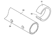
本実施形態の植物栽培装置1では、図3、図4の様に筒状空間2内に送風路形成部材65が内蔵されている。送風路形成部材65は、図7の様に樹脂で作られた本管80と、本管80の周囲に設けられた多数の風量調整手段81及び本管80に内蔵された小型送風機85によって構成されている。
In the
送風路形成部材65の本管80には図8の様に多数の送風口84が設けられている。送風口84は円形の開口である。
風量調整手段81は、本管80よりもやや太い径の樹脂管を短く切り、且つ軸方向にスリット82を形成したものである。風量調整手段81の断面形状は「C」状である。
風量調整手段81は、本管80の送風口84に装着されている。即ち風量調整手段81は、本管80の周囲を取り巻く状態で本管80に装着されている。
風量調整手段81は、本管80に対して回転可能であり、送風口84の開度を調節することができる。即ち図9(a)の様にスリット82を送風口84の位置に合わせることによって送風口84の実質的開口面積を100パーセントとすることができる。また図9(c)の様にスリット82を送風口84の反対側に回すと、送風口84を閉鎖することができる。図9(b)の様にスリット82の一部を送風口84と合致させることにより、送風口84の実質的開口面積を絞ることができる。
As shown in FIG. 8, a large number of
The air volume adjusting means 81 is formed by cutting a resin pipe having a diameter slightly larger than that of the
The air volume adjusting means 81 is attached to the
The air volume adjusting means 81 is rotatable with respect to the
本管80には内径の大きい太管83が直列に接続されており、当該太管83内に小型送風機85が内蔵されている。小型送風機85を駆動するモータ86は、直流モータ等の回転数を任意に変更できるものである。小型送風機85は軸流ファンである。
A
次に培養液の循環路について説明する。
本実施形態の植物栽培装置1では、図4の様に植物栽培装置1の下部に培養液供給装置206がある。培養液供給装置206は培養液タンク207とポンプ208を備えている。そして培養液タンク207とポンプ208の吸い込み側が配管接続され、さらにポンプ208の吐出側と培養液供給口35が配管接続されている。さらに養液槽3に設けられたオーバーフロー管7が培養液タンク207に配管接続されている。そのため、ポンプ208を起動すると、培養液タンク207内の培養液がポンプ208で加圧されて培養液供給口35に送られ、養液槽3に供給される。また培養液はオーバーフロー管7によって構成される排水口8から排水されて培養液タンク207に戻る。こうして培養液は、養液槽3と培養液タンク207の間を循環する。
Next, the circulation path of the culture solution will be described.
In the
植物保持具30は、比重の軽い素材で作られた板であり、複数の開口31が設けられている。開口31には植物の苗が保持される。植物保持具30は、浮力が強く、単体で水に浮くばかりでなく、植物を保持した状態であっても沈まない。
植物保持具30は、開口31に植物が保持された状態で、養液槽3の培養液に浮かされる。
The
The
植物栽培システム100は、前記した様に植物栽培装置1が複数段且つ複数列に渡って設置されたものである。
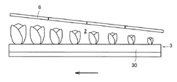
本実施形態では、屋根部材6の高さは全体として勾配が付けられており、図12の様に、右側の高さが低く、左側に行くほど屋根部材6の高さが高くなってゆく。即ち、植物保持具30の流れ方向を基準として、上流側は屋根部材6の高さが低く、下流側は屋根部材6の高さが高い。
In the
In the present embodiment, the height of the
本実施形態では、養液槽3に植物保持具30が複数浮かべられ、植物保持具30は外力によって図1、図12の矢印の方向に進められる。即ち養液槽3の水面を覆うように植物保持具30が敷きつめられ、植物保持具30が養液槽3の水面に浮かされている。そのため人力によって、養液槽3上の植物保持具30を押すと、植物保持具30は容易に移動する。即ち植物保持具30は、筏のごとく養液槽3の水面に浮いており、上流側にある植物保持具30を押すと、植物保持具30は下流側に流れてゆく。また下流側に流れた植物保持具30は、隣接する植物保持具30を押し、当該植物保持具30も下流側に流れる。結果的に、養液槽3に浮かべられた全ての植物保持具30が下流側に流れてゆく。
In the present embodiment, a plurality of
次に、本実施形態の植物栽培装置1の機能について説明する。
本実施形態の植物栽培装置1では、養液槽3に培養液が満たされる。そのため筒状空間2内に養液槽の液面があり、液面は筒状空間2で覆われている。そして植物保持具30の開口31に植物の苗を保持させ、養液槽3の上流側に浮かべられる。
また照明基板(照明手段)241によって苗の成長に要する光が供給される。本実施形態では、筒状空間2の内面で光が反射するから、筒状空間2の内壁に当たった光も反射して苗に当たる。
さらに図示しない空調設備等によって、筒状空間2内の温度、湿度及び二酸化炭素濃度が調節される。
なお外気の侵入を防いで筒状空間2内の環境を維持する目的と、筒状空間2内に埃等が侵入することを防ぐ目的から、筒状空間2は大気に比べてやや正圧に保っておくことが望ましい。
Next, the function of the
In the
Further, the light required for the growth of seedlings is supplied by the lighting substrate (lighting means) 241. In the present embodiment, since the light is reflected on the inner surface of the
Further, the temperature, humidity and carbon dioxide concentration in the
The
筒状空間2内の養液槽3に浮かべられた植物保持具30は、一定時間ごとに下流側に移動させられる。例えば24時間ごとに、植物保持具30が人力で押され、植物保持具30が下流側に流される。
The
植物栽培装置1では、10日から30日程度の日数をかけて植物保持具30を始端から終端に送る。ここで、時間の経過と共に植物保持具30に保持された苗が成長するが、本実施形態では、下流側に向かう程、屋根部材6の高さが高くなっている。そのため苗の成長を妨げず、且つ苗に対して適切に光をあてることができる。即ち幼苗の時期は、苗の丈が低い。本実施形態では、上流側は屋根部材6の高さが低く、苗と照明基板(照明手段)241の距離が近い。そのため苗に集中的に光を照射することができる。
その一方、苗が成長して丈が高くなる位置では屋根部材6の高さが高く、苗にまんべんなく光を照射することができる。
In the
On the other hand, at the position where the seedlings grow and become taller, the height of the
そして植物栽培装置1の終端で植物保持具30を取り出し、成長した植物を収穫するか、あるいは植物保持具30を再度他の植物栽培装置1に搬入して苗をより大きく成長させる。
即ち、植物栽培装置1の始端に苗を植えつけた植物保持具30を挿入し、照明基板(照明手段)241を点灯して苗の葉に光を当て、苗の根から養液槽3の培養液を吸収させて苗を育てる。そして養液槽3に浮かぶ植物保持具30を押して下流側へ流し、筒状空間2内をゆっくりと移動させる。そして植物保持具30が一つの植物栽培装置1の終端、あるいは複数の植物栽培装置1を通過して終端に至った際には、苗は食用に供される程度に成長しており、植物保持具30から収穫されて出荷される。
Then, the
That is, the
また本実施形態の植物栽培装置1では、植物栽培装置1の温度を調整する際、補助的に冷却水供給ラインの管36から水が放出され、照明基板(照明手段)241による過度の昇温が抑制される。
Further, in the
また本実施形態の植物栽培装置1では、筒状空間2内の所望のエリアに風を発生させることができる。
即ち本実施形態の植物栽培システム100は、図示しない空調装置を有し、空調装置の排気側はダクト等によって植物栽培装置1の筒状空間2の送風路形成部材65の本管80に接続されている。
送風路形成部材65は、筒状空間2を軸方向に貫通して配されるが、中途部分に小型送風機85が設けられている。より具体的には、植物栽培装置1に一定間隔ごとに小型送風機85が設けられている。
そして本管80には多数の送風口84が設けられている。
そのため空調装置の吐出側の圧力が不足していても、中途の小型送風機85で増圧され、各送風口84から筒状空間2を内に風を送りだすことができる。
Further, in the
That is, the
The blower
The main 80 is provided with a large number of
Therefore, even if the pressure on the discharge side of the air conditioner is insufficient, the pressure is increased by the
また送風口84の開度を全閉から全開まで変化させることができるので、必要な場所に風を送ることができる。
なお本実施形態では、手動によって送風口84の開度を調節するが、モータ弁等を使用して送風口84の開度を遠隔操作する方法も推奨される。
また送風口84に動力で駆動するルーバーを設け、定期的に送風方向を変更することも推奨される。
送風量の制御は、モータに供給される電流、モータの回転数、送風方向といった情報に基づいて行うことができる。
Further, since the opening degree of the
In the present embodiment, the opening degree of the
It is also recommended that the
The amount of air blown can be controlled based on information such as the current supplied to the motor, the rotation speed of the motor, and the direction of air blown.
送風路形成部材65は複数本設けられていてもよい。例えば送風路形成部材65を複数系統設け、送風路形成部材65を流れる空気の温度や湿度を違えてよい。
また送風路形成部材65を複数設け、その内の一本または複数本を吸引用に使用してもよい。例えば二酸化炭素濃度が高いエリアがあれば吸引用の送風路形成部材で当該領域の空気を吸引して置換してもよい。
A plurality of air
Further, a plurality of air
また送風路形成部材65には、小型送風機85が複数設けられており、小型送風機85同士の間に送風口84が設けられているから、小型送風機85の送風強度によっては一部の送風口84が負圧傾向となる場合もある。
例えば一つの小型送風機85の送風が弱く、その先の小型送風機85の吸引力が強い場合には、二つの小型送風機85の間に設けられた送風口84は負圧傾向となり、筒状空間2内の空気を吸引する。
そのため故意に送風口84を負圧傾向として筒状空間2内の空気を吸引し、風を起こしたり二酸化炭素等を拡散させてもよい。
送風路形成部材65の断面形状は任意である。
Further, since the blower
For example, when the air blown by one
Therefore, the air in the
The cross-sectional shape of the air
送風口84から放出された送風は、送風口84の近傍に局地的な風を発生させる。即ち本実施形態では、送風して筒状空間2内の空気を動かす送風手段を有し、送風手段は、エリアごとに送風量を異ならせることができ、局地的に風を発生させることができる。
送風口84近傍のエリアを離れると、空気の流れが緩慢となり、筒状空間2全体に拡散されて筒状空間2の圧力が上昇する。
The air blown from the
When leaving the area near the
本実施形態の植物栽培装置1は、培養液の液面が筒状空間2内にあり、植物を育成させる空間が筒状空間2に限定されているから、温度、湿度、二酸化炭素等を制御する空間が狭い。そのためこれらを制御するのに要するエネルギーが少ない。
また植物栽培装置1内に害虫が侵入した場合は、一条の植物栽培装置1の運転を停止させて害虫駆除を行うことができ、被害が広がらない。
また本実施形態の植物栽培装置1では、清浄に保つべき空間が、筒状空間2に限定されるから、従来の植物工場の様な厳格な害虫侵入防止措置を講じたり、大がかりな清浄装置を設置する必要はない。
そのため廃工場や倉庫に本実施形態の植物栽培装置1や植物栽培システム100を設置して作物を生産することもできる。
また本実施形態の植物栽培システム100は、植物を育成させる空間が筒状空間2に限定されているから、異なる植物を一つの植物栽培システム100で育成することもできる。
In the
Further, when a pest invades the
Further, in the
Therefore, the
Further, in the
以上説明した実施形態では、屋根部材6の形状が円弧形状であったが、本発明はこの構成に限定されるものではなく、図13、図14に示す植物栽培装置50の様に平板状の屋根部51であってもよい。
図13、図14に示す植物栽培装置50では、照明手段として、棒状の発光装置52が採用されている。発光装置52は、棒状の基板にLED等の発光素子53が多数設けられたものである。
In the embodiment described above, the shape of the
In the
1 植物栽培装置
2 筒状空間
3 養液槽
7 オーバーフロー管
8 排水口
30 植物保持具
35 培養液供給口
50 植物栽培装置
53 発光素子
65 送風路形成部材
100 植物栽培システム
241 照明基板(照明手段)
206 培養液供給装置
207 培養液タンク
208 ポンプ
243 LED(発光素子)
1
206 Culture
Claims (8)
養液槽に培養液が満たされ、複数の植物保持具に植物を保持した状態で当該複数の植物保持具が養液槽に設置され、前記照明手段で植物に光が照射され、養液槽の一端側から他端側に向かって植物保持具が移動される植物栽培装置において、
天面と側面が覆われた筒状空間内に前記養液槽の液面があり、
前記筒状空間の天面は円弧状に湾曲しており、
前記天面に照明手段が設置されており、
前記照明手段は、複数の発光素子を有し、
天面の中央領域における前記発光素子の配置密度は、天面の裾領域における前記発光素子の配置密度と比べて低く、
前記筒状空間の高さが植物栽培装置の長手方向の位置で相違することを特徴とする植物栽培装置。 It has a groove-shaped nutrient solution tank, lighting means, and multiple plant holders for holding plants.
The nutrient solution tank is filled with the culture solution, and the plurality of plant holders are installed in the nutrient solution tank in a state where the plants are held by the plurality of plant holders. In a plant cultivation device in which the plant holder is moved from one end side to the other end side of the
The liquid level of the nutrient solution tank is in a tubular space covered with the top surface and side surfaces.
The top surface of the tubular space is curved in an arc shape.
Lighting means is installed on the top surface,
The lighting means has a plurality of light emitting elements and has a plurality of light emitting elements.
The arrangement density of the light emitting element in the central region of the top surface is lower than the arrangement density of the light emitting element in the hem region of the top surface.
A plant cultivation apparatus characterized in that the height of the tubular space differs depending on the position in the longitudinal direction of the plant cultivation apparatus.
Priority Applications (1)
| Application Number | Priority Date | Filing Date | Title |
|---|---|---|---|
| JP2016043030A JP6911222B2 (en) | 2016-03-07 | 2016-03-07 | Plant cultivation equipment and plant cultivation system |
Applications Claiming Priority (1)
| Application Number | Priority Date | Filing Date | Title |
|---|---|---|---|
| JP2016043030A JP6911222B2 (en) | 2016-03-07 | 2016-03-07 | Plant cultivation equipment and plant cultivation system |
Publications (2)
| Publication Number | Publication Date |
|---|---|
| JP2017158437A JP2017158437A (en) | 2017-09-14 |
| JP6911222B2 true JP6911222B2 (en) | 2021-07-28 |
Family
ID=59852763
Family Applications (1)
| Application Number | Title | Priority Date | Filing Date |
|---|---|---|---|
| JP2016043030A Active JP6911222B2 (en) | 2016-03-07 | 2016-03-07 | Plant cultivation equipment and plant cultivation system |
Country Status (1)
| Country | Link |
|---|---|
| JP (1) | JP6911222B2 (en) |
Families Citing this family (1)
| Publication number | Priority date | Publication date | Assignee | Title |
|---|---|---|---|---|
| JP6660355B2 (en) * | 2017-08-21 | 2020-03-11 | 株式会社大一商会 | Gaming machine |
Family Cites Families (10)
| Publication number | Priority date | Publication date | Assignee | Title |
|---|---|---|---|---|
| JPS4749265B1 (en) * | 1969-06-21 | 1972-12-11 | ||
| JPS50142337A (en) * | 1974-04-26 | 1975-11-17 | ||
| JPS5169030A (en) * | 1974-12-12 | 1976-06-15 | Kubota Ltd | |
| JPS6255028A (en) * | 1985-09-04 | 1987-03-10 | 三菱電機株式会社 | Plant culture apparatus |
| JPS62126919A (en) * | 1985-11-26 | 1987-06-09 | 諏訪 賢太郎 | Apparatus for growing plant such as vegetables |
| JP2594614B2 (en) * | 1988-05-16 | 1997-03-26 | 藤田 光夫 | Honeycomb type hydroponics equipment |
| JPH02171125A (en) * | 1988-12-26 | 1990-07-02 | Sanyo Electric Co Ltd | Method for culturing plant and apparatus therefor |
| JPH0576248A (en) * | 1991-09-20 | 1993-03-30 | Seed Kaihatsu Kk | Simple-type multistage soil and recyclable plastic greenhouse with hydroponic function |
| JP5481743B2 (en) * | 2009-03-30 | 2014-04-23 | 鹿島建設株式会社 | Submerged hydroponic cultivation apparatus, temperature control system, plant cultivation facility, and method |
| KR101022025B1 (en) * | 2010-08-17 | 2011-03-16 | 조장은 | Plants cultivation apparatus |
-
2016
- 2016-03-07 JP JP2016043030A patent/JP6911222B2/en active Active
Also Published As
| Publication number | Publication date |
|---|---|
| JP2017158437A (en) | 2017-09-14 |
Similar Documents
| Publication | Publication Date | Title |
|---|---|---|
| JP6865974B2 (en) | Plant cultivation equipment and plant cultivation method | |
| JP6760436B2 (en) | Plant cultivation methods and facilities | |
| JP4314316B1 (en) | Plant cultivation equipment for home use | |
| JP2011244705A (en) | Method for cultivating plant | |
| JP7033291B2 (en) | Plant cultivation equipment, plant cultivation system and plant cultivation method | |
| JP2011120569A (en) | Method for controlling temperature for plant cultivation, temperature controlling device for plant cultivation, plant cultivation unit, and plant cultivation plant | |
| JP2019024452A (en) | Plant cultivation device and plant cultivation method | |
| JP2005034043A (en) | Plant for cultivating soil culture plant | |
| JP6911222B2 (en) | Plant cultivation equipment and plant cultivation system | |
| JP2017184645A (en) | Plant cultivation greenhouse | |
| KR101396436B1 (en) | Cultivation system of greenhouse plant | |
| JP2011244706A (en) | Method for cultivating plant | |
| JP2009055871A (en) | Method of spraying hydroponics | |
| WO2022092030A1 (en) | Plant cultivation device and method | |
| JPH01235524A (en) | Fully controlled plant factory | |
| KR101757216B1 (en) | Cartridge type hydroponic combined biological sayukgi | |
| JP6477148B2 (en) | Hydroponics method | |
| KR101248986B1 (en) | A plant cultivation box transfer equipment | |
| JP2007061014A (en) | Greenhouse device with dehumidification function | |
| RU2717999C1 (en) | Method for field production of minitubers from potato microplants in a protected medium | |
| KR102302273B1 (en) | Plant cultivation system | |
| JP2002142585A (en) | Method for cultivating plant | |
| CN202035339U (en) | Heat exchange and ventilation system for greenhouse | |
| JP2019136029A (en) | Plant cultivation apparatus | |
| JP2016073263A (en) | Carbon dioxide application facility and application method for crops grown in house, and the like |
Legal Events
| Date | Code | Title | Description |
|---|---|---|---|
| A621 | Written request for application examination |
Free format text: JAPANESE INTERMEDIATE CODE: A621 Effective date: 20190207 |
|
| A521 | Written amendment |
Free format text: JAPANESE INTERMEDIATE CODE: A523 Effective date: 20190228 |
|
| A977 | Report on retrieval |
Free format text: JAPANESE INTERMEDIATE CODE: A971007 Effective date: 20191028 |
|
| A131 | Notification of reasons for refusal |
Free format text: JAPANESE INTERMEDIATE CODE: A131 Effective date: 20191031 |
|
| A601 | Written request for extension of time |
Free format text: JAPANESE INTERMEDIATE CODE: A601 Effective date: 20191226 |
|
| A521 | Written amendment |
Free format text: JAPANESE INTERMEDIATE CODE: A523 Effective date: 20200227 |
|
| A131 | Notification of reasons for refusal |
Free format text: JAPANESE INTERMEDIATE CODE: A131 Effective date: 20200423 |
|
| A601 | Written request for extension of time |
Free format text: JAPANESE INTERMEDIATE CODE: A601 Effective date: 20200619 |
|
| A521 | Written amendment |
Free format text: JAPANESE INTERMEDIATE CODE: A523 Effective date: 20200820 |
|
| TRDD | Decision of grant or rejection written | ||
| A01 | Written decision to grant a patent or to grant a registration (utility model) |
Free format text: JAPANESE INTERMEDIATE CODE: A01 Effective date: 20210128 |
|
| A61 | First payment of annual fees (during grant procedure) |
Free format text: JAPANESE INTERMEDIATE CODE: A61 Effective date: 20210204 |
|
| R150 | Certificate of patent or registration of utility model |
Ref document number: 6911222 Country of ref document: JP Free format text: JAPANESE INTERMEDIATE CODE: R150 |