JP6906128B2 - Wafer test equipment - Google Patents
Wafer test equipment Download PDFInfo
- Publication number
- JP6906128B2 JP6906128B2 JP2020093761A JP2020093761A JP6906128B2 JP 6906128 B2 JP6906128 B2 JP 6906128B2 JP 2020093761 A JP2020093761 A JP 2020093761A JP 2020093761 A JP2020093761 A JP 2020093761A JP 6906128 B2 JP6906128 B2 JP 6906128B2
- Authority
- JP
- Japan
- Prior art keywords
- wafer
- slide
- unit
- tray
- drive mechanism
- Prior art date
- Legal status (The legal status is an assumption and is not a legal conclusion. Google has not performed a legal analysis and makes no representation as to the accuracy of the status listed.)
- Active
Links
Images


Classifications
-
- G—PHYSICS
- G01—MEASURING; TESTING
- G01R—MEASURING ELECTRIC VARIABLES; MEASURING MAGNETIC VARIABLES
- G01R31/00—Arrangements for testing electric properties; Arrangements for locating electric faults; Arrangements for electrical testing characterised by what is being tested not provided for elsewhere
- G01R31/26—Testing of individual semiconductor devices
-
- G—PHYSICS
- G01—MEASURING; TESTING
- G01R—MEASURING ELECTRIC VARIABLES; MEASURING MAGNETIC VARIABLES
- G01R31/00—Arrangements for testing electric properties; Arrangements for locating electric faults; Arrangements for electrical testing characterised by what is being tested not provided for elsewhere
- G01R31/28—Testing of electronic circuits, e.g. by signal tracer
-
- H—ELECTRICITY
- H01—ELECTRIC ELEMENTS
- H01L—SEMICONDUCTOR DEVICES NOT COVERED BY CLASS H10
- H01L21/00—Processes or apparatus adapted for the manufacture or treatment of semiconductor or solid state devices or of parts thereof
- H01L21/67—Apparatus specially adapted for handling semiconductor or electric solid state devices during manufacture or treatment thereof; Apparatus specially adapted for handling wafers during manufacture or treatment of semiconductor or electric solid state devices or components ; Apparatus not specifically provided for elsewhere
- H01L21/68—Apparatus specially adapted for handling semiconductor or electric solid state devices during manufacture or treatment thereof; Apparatus specially adapted for handling wafers during manufacture or treatment of semiconductor or electric solid state devices or components ; Apparatus not specifically provided for elsewhere for positioning, orientation or alignment
Description
本発明はウエハー試験装置に関し、詳細には、半導体ウエハーの前工程試験装置、後工程試験装置、及びバーンイン試験装置等に使用されるウエハーの電極にコンタクトするための端子を有したプローブカードと、テスト回路等を搭載するロードボードと、ウエハーを載置するウエハートレーと、密閉空間を形成する真空チャンバーと、を有したウエハー試験ユニットと、
ウエハーの電極とプローブカードの端子間の位置合せを行うウエハー位置決めステージと、位置情報撮影機構と、昇降機構とを有するウエハー位置決めユニットと、
複数のウエハー試験ユニットを搭載する装置フレームと、を備え、
ウエハーの電極とプローブカードの端子間を真空圧で加圧接触させて試験を行うウエハー試験装置に関する。The present invention relates to a wafer test apparatus, and more particularly, a probe card having a terminal for contacting a wafer electrode used in a pre-process test apparatus, a post-process test apparatus, a burn-in test apparatus, and the like of a semiconductor wafer. A wafer test unit having a load board on which a test circuit or the like is mounted, a wafer tray on which a wafer is placed, and a vacuum chamber for forming a closed space.
A wafer positioning stage that aligns the wafer electrodes and probe card terminals, a wafer positioning unit that has a position information imaging mechanism, and an elevating mechanism.
Equipped with an equipment frame for mounting multiple wafer test units,
The present invention relates to a wafer test apparatus for performing a test by pressurizing contact between a wafer electrode and a probe card terminal with a vacuum pressure.
ウエハーの試験は、半導体パッケージの試験と同様に高温或いは低温の環境下で、プローバーと呼ばれる試験装置を使用してストレス試験や機能試験等の電気的特性試験が行われ、ウエハーの試験が終了後ウエハーの切断・組立工程を経て半導体パッケージとして、バ―ンインソケットやテストソケットに搭載され、バーンイン試験や後工程試験が行われている。 Similar to the semiconductor package test, the wafer test is performed in an environment of high temperature or low temperature using a test device called a prober to perform electrical property tests such as stress test and functional test, and after the wafer test is completed. After the wafer cutting and assembling process, it is mounted on a burn-in socket or a test socket as a semiconductor package, and a burn-in test and a post-process test are performed.
これに対して、ウエハーの試験でプローバー装置のウエハーチャック部をウエハープレートと移動ステージに分離し、多段構成のマルチウエハー試験装置を実現し、プローブカードとウエハープレートで囲まれる空間を真空吸引力により加圧接触させて、ウエハーの試験を行うウエハー検査装置が特許文献1に開示されている。 On the other hand, in the wafer test, the wafer chuck part of the prober device is separated into the wafer plate and the moving stage to realize a multi-wafer test device with a multi-stage configuration, and the space surrounded by the probe card and the wafer plate is created by vacuum suction force. Patent Document 1 discloses a wafer inspection apparatus that tests a wafer by pressure contact.
該特許文献1には、ウエハーを、ウエハープレートを介してチャック部材に載置してプローブカードと対向する位置まで搬送し、搬送したウエハーをウエハープレートと共に、昇降装置を用いてプローブカードに向かって移動させて、ウエハーに設けられた半導体デバイスの複数の電極をプローブカードに設けられた複数の端子にそれぞれ当接させた後、ウエハーをさらにプローブカードに向かってオーバードライブさせ、その後プローブカードとウエハープレートとの間の空間を減圧して、半導体デバイスの電極とプローブカードの端子との当接状態を保持し、チャック部材をウエハープレートから切り離すプローブカードへの当接手段が開示され、チャック部材は別のプローブカードに対応する位置まで移動して、次のウエハーの試験に備えるという発明が開示されている。 In Patent Document 1, a wafer is placed on a chuck member via a wafer plate and conveyed to a position facing the probe card, and the conveyed wafer is conveyed together with the wafer plate toward the probe card by using an elevating device. After moving and bringing the plurality of electrodes of the semiconductor device provided on the wafer into contact with the plurality of terminals provided on the probe card, the wafer is further overdriven toward the probe card, and then the probe card and the wafer are further driven. The space between the plate and the probe card is depressurized to maintain the contact state between the electrode of the semiconductor device and the terminal of the probe card, and the means for contacting the probe card that separates the chuck member from the wafer plate is disclosed. The invention is disclosed to move to a position corresponding to another probe card to prepare for the next wafer test.
すなわち、特許文献1に係る発明は、ウエハーの搭載ステージであるウエハープレートに載置されたウエハーとプローブカードの電気的接続に真空圧を利用し、さらにウエハーの搭載ステージをウエハープレートと該ウエハープレートを押し上げるアライメント機構を備えた移動ステージに分離する方式を採用し、多段構成のウエハー検査装置を実現している。 That is, the invention according to Patent Document 1 utilizes vacuum pressure for electrical connection between a wafer mounted on a wafer plate, which is a wafer mounting stage, and a probe card, and further uses a wafer mounting stage as a wafer plate and the wafer plate. A multi-stage wafer inspection device is realized by adopting a method of separating into a moving stage equipped with an alignment mechanism that pushes up the wafer.
特許文献1に記載の発明は、ウエハー搭載部をウエハープレートとウエハープレートを押し上げる部材に分離し、前記ウエハープレートを押し上げる部材とアライメント機構を備えたユニットを移動ステージとし、前記ウエハープレートにウエハーが載置されアライメントを行い、ウエハープレートをプローブカード側に押上げ、真空圧で吸引した後、移動ステージを下降させ移動して、次のプローバーへのウエハーの搭載、位置合せ、及び取出しに備える構成にすることにより、従来装置に比較しプローバー機構の高さを低くし、多段構成のウエハー検査装置を実現している。
しかしながら、ウエハー試験装置の下側に移動ステージが設置され、さらに移動ステージでウエハープレートを上下に移動させる為、ウエハー試験装置の必要とする高さ方向のスペースは大きくなり、一列の装置フレームに多数の試験装置を積載することは困難であった。
また、移動ステージの昇降でウエハーを載置したウエハープレートを昇降させることから、移動ステージの昇降時の垂直走行性とウエハー試験装置に搭載されるプローブカードの水平性が重要になり、ウエハー試験装置を多段に積載する場合それぞれのウエハー試験装置の水平搭載と移動ステージの垂直走行性が位置精度に大きく影響してくるという課題がある。In the invention described in Patent Document 1, the wafer mounting portion is separated into a wafer plate and a member that pushes up the wafer plate, and a unit having the member that pushes up the wafer plate and an alignment mechanism is used as a moving stage, and the wafer is mounted on the wafer plate. After being placed and aligned, the wafer plate is pushed up toward the probe card, sucked by vacuum pressure, and then the moving stage is lowered and moved to prepare for mounting, aligning, and taking out the wafer on the next prober. By doing so, the height of the prober mechanism is lowered as compared with the conventional apparatus, and a multi-stage wafer inspection apparatus is realized.
However, since the moving stage is installed under the wafer test device and the wafer plate is moved up and down by the moving stage, the space required by the wafer test device in the height direction becomes large, and many of them are placed in a row of device frames. It was difficult to load the test equipment of.
In addition, since the wafer plate on which the wafer is placed is raised and lowered by raising and lowering the moving stage, vertical running performance when raising and lowering the moving stage and horizontality of the probe card mounted on the wafer test device are important, and the wafer test device. When the wafers are loaded in multiple stages, there is a problem that the horizontal mounting of each wafer test device and the vertical running performance of the moving stage greatly affect the position accuracy.
したがって本発明が解決しようとする課題は、ウエハー試験装置(本文ではウエハー試験ユニットと称す)を移動ステージ(本文ではウエハー位置決めステージと称す)に相対するようにスライドさせるユニットスライド機構をウエハー試験装置に備えることで、多数のウエハー試験装置を搭載する多段構成のウエハー試験装置を提供し、移動ステージのウエハープレート(本文ではウエハートレーと称す)載置面をウエハープレートの傾きに追随させ、さらにウエハープレートの平面に対し垂直に昇降させる手段を備えることで、ウエハー試験装置の搭載時の水平性と、移動ステージの垂直走行性に依存することのない位置合せ手段を備えるウエハー試験装置を提供することにある。 Therefore, the problem to be solved by the present invention is to provide a wafer test device with a unit slide mechanism that slides a wafer test device (referred to as a wafer test unit in the text) so as to face a moving stage (referred to as a wafer positioning stage in the text). By providing, a multi-stage wafer test device equipped with a large number of wafer test devices is provided, and the wafer plate (referred to as a wafer tray in the text) mounting surface of the moving stage is made to follow the inclination of the wafer plate, and further, the wafer plate is provided. By providing a means for raising and lowering the wafer perpendicularly to the plane of the wafer, the wafer test device is provided with a positioning means that does not depend on the horizontality when the wafer test device is mounted and the vertical running property of the moving stage. be.
本発明の課題を解決するための手段は、下記のとおりである。 The means for solving the problem of the present invention is as follows.
第1に、
ウエハーの電極とプローブカードの端子間を、真空圧で加圧接触させて試験を行うウエハー試験装置であり、
テスト回路等を搭載するロードボードと、前記プローブカードと、前記ウエハーを載置するウエハートレーと、前記ロードボードと前記プローブカードで挟まれる空間及び前記プローブカードと前記ウエハートレーで挟まれる空間の周囲を囲んで密閉空間を形成する真空チャンバーと、を有するウエハー試験ユニットと、
前記ウエハー試験ユニットの前面側に配置され、前記ウエハートレーを載置し前記ウエハーの電極と前記プローブカードの端子間の位置合せを行うウエハー位置決めステージと、カメラを有する位置情報撮影機構と、前記ウエハー位置決めステージと前記位置情報撮影機構を昇降させるユニット昇降機構と、を有するウエハー位置決めユニットと、
前記ウエハー試験ユニットを搭載する装置フレームと、
を備え、
前記ウエハー試験ユニットは、
前記プローブカードに相対するように前記真空チャンバーに保持されている前記ウエハートレーが、該ウエハー試験ユニットの前面側に配置された前記ウエハー位置決めステージに相対するように、該ウエハー試験ユニットをスライドさせるユニットスライド機構を備えることを特徴とするウエハー試験装置。First,
This is a wafer test device that conducts tests by pressurizing and contacting the electrodes of the wafer and the terminals of the probe card with vacuum pressure.
Around a load board on which a test circuit or the like is mounted, a probe card, a wafer tray on which the wafer is placed, a space sandwiched between the load board and the probe card, and a space sandwiched between the probe card and the wafer tray. A wafer test unit with a vacuum chamber that surrounds and forms an enclosed space,
A wafer positioning stage arranged on the front side of the wafer test unit, on which the wafer tray is placed, and positioning between the electrodes of the wafer and the terminals of the probe card, a position information photographing mechanism having a camera, and the wafer. A wafer positioning unit having a positioning stage and a unit elevating mechanism for raising and lowering the position information photographing mechanism, and
An apparatus frame on which the wafer test unit is mounted and
With
The wafer test unit is
A unit that slides the wafer test unit so that the wafer tray held in the vacuum chamber so as to face the probe card faces the wafer positioning stage arranged on the front side of the wafer test unit. A wafer test apparatus including a slide mechanism.
第2に、
前記ユニットスライド機構は、
スライドユニットとスライドガイドを有するリニアスライド機構と、
前記スライドユニットをスライドさせる駆動機構と、
前記リニアスライド機構と前記駆動機構が搭載されるフレーム部材と、
を備え、
前記スライドユニットが前記ウエハー試験ユニットに連結され、
前記フレーム部材が前記装置フレームに設置されることを特徴とする第1に記載するウエハー試験装置。Second,
The unit slide mechanism
A linear slide mechanism with a slide unit and slide guide,
A drive mechanism that slides the slide unit and
The linear slide mechanism, the frame member on which the drive mechanism is mounted, and
With
The slide unit is connected to the wafer test unit,
The wafer test apparatus according to the first aspect, wherein the frame member is installed in the apparatus frame.
第3に、
前記ウエハー位置決めステージは、
スライドした前記ウエハー試験ユニットのウエハートレーに相対するように配置され、
X方向とY方向と回転方向の位置制御を行うアライメントステージと、
前記アライメントステージのウエハートレー載置面の傾きを、前記ウエハートレーの傾きに追随させるアライメントステージ揺動機構と、
前記ウエハートレーを、前記真空チャンバーに保持される位置と前記ウエハーが載置される位置との間を昇降させるアライメントステージ昇降機構と、
を備えることを特徴とする第1から第2に記載するウエハー試験装置。Third,
The wafer positioning stage is
Arranged so as to face the wafer tray of the sliding wafer test unit.
An alignment stage that controls the positions in the X, Y, and rotation directions,
An alignment stage swing mechanism that makes the inclination of the wafer tray mounting surface of the alignment stage follow the inclination of the wafer tray.
An alignment stage elevating mechanism that elevates and elevates the wafer tray between the position held in the vacuum chamber and the position on which the wafer is placed.
The wafer test apparatus according to the first to the second.
第4に、
前記アライメントステージ揺動機構は、
前記ウエハー試験ユニットがスライドし前記ウエハー位置決めステージが前記ユニット昇降機構で押し上げられる時、前記真空チャンバーの下面の四隅に接触する突き当て部材と、
前記突き当て部材を有する揺動板と、
可動部と固定部を有する球面滑り軸受と、
前記突き当て部材が前記真空チャンバーに接触した時、前記揺動板の外周部に加わる荷重を支えるバネ部材と、
前記揺動板の下側に該揺動板が揺動するスペースを保って設置される揺動機構取付け板と、を備え、
前記突き当て部材は、
前記真空チャンバーに接触した時、前記位置情報撮影機構が前記ウエハートレーと前記プローブカードの間に挿入され、前記ウエハーの電極と前記プローブカードの端子の位置情報を取得できる高さを有し、
前記球面滑り軸受は、
前記揺動板と前記揺動機構取付け板の間の中央部に設置され、
前記バネ部材は、
前記球面滑り軸受の外周部に複数配置されることを特徴とする第3に記載するウエハー試験装置。Fourth,
The alignment stage swing mechanism is
When the wafer test unit slides and the wafer positioning stage is pushed up by the unit elevating mechanism, the abutting members that come into contact with the four corners of the lower surface of the vacuum chamber and
A rocking plate having the abutting member and
Spherical plain bearings with moving and fixed parts,
A spring member that supports a load applied to the outer peripheral portion of the rocking plate when the abutting member comes into contact with the vacuum chamber, and a spring member.
A rocking mechanism mounting plate, which is installed under the rocking plate while maintaining a space for the rocking plate to swing, is provided.
The abutting member is
When in contact with the vacuum chamber, the position information photographing mechanism is inserted between the wafer tray and the probe card, and has a height capable of acquiring position information of the electrodes of the wafer and the terminals of the probe card.
The spherical plain bearing is
It is installed in the central part between the rocking plate and the rocking mechanism mounting plate, and is installed.
The spring member is
The third wafer test apparatus according to the third feature, wherein a plurality of wafer test devices are arranged on the outer peripheral portion of the spherical slide bearing.
第5に、
前記アライメントステージ昇降機構は、
前記揺動板と、
前記アライメントステージを搭載するアライメントステージ取付け板と、
ボールネジと、前記ボールネジの駆動でスライドする駆動機構スライド軸と、前記駆動機構スライド軸と嵌合する駆動機構スライドユニットと、を有する駆動機構と、
前記駆動機構を駆動する駆動モーターと、
スライド軸とスライドユニットを有するスライド機構と、
を備え、
前記駆動機構は、
前記駆動機構スライドユニットが、前記揺動板の四隅の所要の箇所に設置され、
前記駆動機構スライド軸の先端が、前記アライメントステージ取付け板の四隅の前記駆動機構スライドユニットが設置される箇所と相対する箇所に連結され、
前記ボールネジが前記揺動板に設置された前記駆動モーターに連結され、
前記スライド機構は、
前記スライドユニットが、前記揺動板の四隅の前記駆動機構スライドユニットが設置されない箇所に設置され、
前記スライド軸の先端が、前記アライメントステージ取付け板の四隅の前記スライドユニットが設置される箇所と相対する箇所に連結されることを特徴とする第3に記載するウエハー試験装置。Fifth,
The alignment stage elevating mechanism is
With the rocking plate
An alignment stage mounting plate on which the alignment stage is mounted and an alignment stage mounting plate
A drive mechanism having a ball screw, a drive mechanism slide shaft that slides by driving the ball screw, and a drive mechanism slide unit that fits with the drive mechanism slide shaft.
The drive motor that drives the drive mechanism and
A slide mechanism with a slide shaft and a slide unit,
With
The drive mechanism
The drive mechanism slide unit is installed at required positions at the four corners of the rocking plate, and the drive mechanism slide unit is installed.
The tips of the drive mechanism slide shafts are connected to the four corners of the alignment stage mounting plate facing the locations where the drive mechanism slide units are installed.
The ball screw is connected to the drive motor installed on the rocking plate, and the ball screw is connected to the drive motor.
The slide mechanism
The slide unit is installed at four corners of the rocking plate where the drive mechanism slide unit is not installed.
The wafer test apparatus according to a third aspect, wherein the tips of the slide shafts are connected to locations facing the locations where the slide units are installed at the four corners of the alignment stage mounting plate.
第6に、
前記アライメントステージ昇降機構の駆動機構が設置される所要の箇所は、
前記アライメントステージ取付け板に加わる荷重と、該アライメントステージ取付け板を昇降させる速度によって、必要数を1から4の間で選ぶことができ、設置される場所は2カ所の場合のみ定め、2カ所設置の場合は四隅の斜めに対向する2カ所に設置されることを特徴とする第5に記載するウエハー試験装置。Sixth,
The required location where the drive mechanism of the alignment stage elevating mechanism is installed is
The required number can be selected from 1 to 4 depending on the load applied to the alignment stage mounting plate and the speed at which the alignment stage mounting plate is moved up and down. In the case of the above, the wafer test apparatus according to the fifth aspect, wherein the wafer test apparatus is installed at two diagonally opposite locations at the four corners.
第7に、
前記アライメントステージ昇降機構は、
前記駆動機構にボールネジ一体型ボールスプラインが使用され、
前記スライド機構にボールスプラインが使用されることを特徴とする第5から第6に記載のウエハー試験装置。Seventh,
The alignment stage elevating mechanism is
A ball spline with an integrated ball screw is used for the drive mechanism.
The wafer test apparatus according to a fifth to sixth aspects, wherein a ball spline is used for the slide mechanism.
第8に、
前記ウエハー試験ユニットは、
前記ユニットスライド機構と、
前記ウエハートレーを、前記真空チャンバーに保持される位置と前記ウエハーが載置される位置との間を昇降させるウエハートレー昇降機構と、
を備えることを特徴とする第1に記載するウエハー試験ユニット。Eighth,
The wafer test unit is
With the unit slide mechanism
A wafer tray elevating mechanism that elevates and elevates the wafer tray between a position held in the vacuum chamber and a position on which the wafer is placed.
The wafer test unit according to the first aspect, which comprises.
第9に、
前記ウエハートレー昇降機構は、
前記真空チャンバーと、
前記ウエハートレーを載置するウエハートレー保持板と、
ボールネジと、前記ボールネジの駆動でスライドする駆動機構スライド軸と、前記駆動機構スライド軸と嵌合する駆動機構スライドユニットと、を有する前記駆動機構と、
ボールネジを駆動する前記駆動モーターと、
スライド軸とスライドユニットを有する前記スライド機構と、
を備え、
前記駆動機構は、
前記駆動機構スライドユニットが、前記真空チャンバーの四隅の所要の箇所に設置され、前期駆動機構スライド軸の先端が、前記ウエハートレー保持板の四隅の前記駆動機構スライドユニットが設置される箇所と相対する箇所に連結され、
前期ボールネジが前記真空チャンバーに設置された前記駆動モーターに連結され、
前記スライド機構は、
前記スライドユニットが、前記真空チャンバーの四隅の前記駆動機構スライドユニットが設置されない箇所に設置され、
前記スライド軸の先端が、前記ウエハートレー保持板の四隅の前記スライドユニットが設置される箇所と相対する箇所に連結されることを特徴とする第8に記載のウエハー試験装置。Ninth,
The wafer tray elevating mechanism is
With the vacuum chamber
A wafer tray holding plate on which the wafer tray is placed and a wafer tray holding plate
The drive mechanism having a ball screw, a drive mechanism slide shaft that slides by driving the ball screw, and a drive mechanism slide unit that fits with the drive mechanism slide shaft.
The drive motor that drives the ball screw and
The slide mechanism having a slide shaft and a slide unit,
With
The drive mechanism
The drive mechanism slide units are installed at required locations at the four corners of the vacuum chamber, and the tips of the drive mechanism slide shafts of the previous term face each other at the four corners of the wafer tray holding plate where the drive mechanism slide units are installed. Connected to the place,
The ball screw of the previous term is connected to the drive motor installed in the vacuum chamber,
The slide mechanism
The slide unit is installed at four corners of the vacuum chamber where the drive mechanism slide unit is not installed.
8. The wafer test apparatus according to the eighth aspect, wherein the tips of the slide shafts are connected to locations facing the locations where the slide units are installed at the four corners of the wafer tray holding plate.
第10に、
前記ウエハートレー昇降機構の駆動機構が設置される所要の箇所は、
前記ウエハートレー保持板に加わる荷重と該ウエハートレー保持板を昇降させる速度によって、必要数を1から4の間で選ぶことができ、設置される場所は2カ所設置の場合のみ定め、2カ所設置の場合は四隅の斜めに対向する2カ所に設置されることを特徴とする第9に記載のウエハー試験装置。Tenth,
The required location where the drive mechanism of the wafer tray elevating mechanism is installed is
The required number can be selected from 1 to 4 depending on the load applied to the wafer tray holding plate and the speed at which the wafer tray holding plate is moved up and down. In the case of the above, the wafer test apparatus according to the ninth aspect, wherein the wafer test apparatus is installed at two diagonally opposite locations at the four corners.
第11に、
前記ウエハートレー昇降機構は、
前記駆動機構にボールネジ一体型ボールスプラインが使用され、
前記スライド機構にボールスプラインが使用されることを特徴とする第9から第10に記載のウエハー試験装置。Eleventh,
The wafer tray elevating mechanism is
A ball spline with an integrated ball screw is used for the drive mechanism.
9. The wafer test apparatus according to a ninth to tenth, wherein a ball spline is used for the slide mechanism.
第12に、
前記ウエハー位置決めステージは、
スライドした前記ウエハー試験ユニットのウエハートレーに相対するように配置され、
X方向とY方向と回転方向の位置制御を行うアライメントステージと、
前記アライメントステージのウエハートレー載置面の傾きを前記ウエハートレーの傾きに追随させるアライメントステージ揺動機構と、
を備えることを特徴とする第8に記載のウエハー試験装置。Twelfth,
The wafer positioning stage is
Arranged so as to face the wafer tray of the sliding wafer test unit.
An alignment stage that controls the positions in the X, Y, and rotation directions,
An alignment stage swing mechanism that makes the inclination of the wafer tray mounting surface of the alignment stage follow the inclination of the wafer tray, and
8. The wafer test apparatus according to the eighth aspect.
第13に、
前記アライメントステージ揺動機構は、
前記ウエハー試験ユニットがスライドし前記ウエハー位置決めステージが前記ユニット昇降機構で押し上げられる時、前記ウエハートレー保持板の下面の四隅に接触する突き当て部材と、
前記突き当て部材を有する前記揺動板と、
可動部と固定部を有する前記球面滑り軸受と、
前記突き当て部材が前記ウエハートレー保持板に接触した時、前記揺動板の外周部に加わる荷重を支える前記バネ部材と、
前記揺動板の下側に該揺動板が揺動するスペースを保って設置される揺動機構取付け板と、を備え、
前記突き当て部材は、
前記ウエハートレー保持板に接触した時、前記アライメントステージが前記ウエハートレーを押し上げて位置制御が行える高さを有し、
前記球面滑り軸受は、
前記揺動板と前記揺動機構取付け板の間の中央部に設置され、
前記バネ部材は、
前記球面軸受が設置される外周部に複数配置されることを特徴とする第12に記載のウエハー試験ユニット。Thirteenth,
The alignment stage swing mechanism is
When the wafer test unit slides and the wafer positioning stage is pushed up by the unit elevating mechanism, abutting members that come into contact with the four corners of the lower surface of the wafer tray holding plate and
The rocking plate having the abutting member and
The spherical plain bearing having a movable part and a fixed part,
When the abutting member comes into contact with the wafer tray holding plate, the spring member that supports the load applied to the outer peripheral portion of the rocking plate and the spring member.
A rocking mechanism mounting plate, which is installed under the rocking plate while maintaining a space for the rocking plate to swing, is provided.
The abutting member is
The alignment stage has a height at which the position can be controlled by pushing up the wafer tray when it comes into contact with the wafer tray holding plate.
The spherical plain bearing is
It is installed in the central part between the rocking plate and the rocking mechanism mounting plate, and is installed.
The spring member is
The twelfth wafer test unit according to twelfth, wherein a plurality of the spherical bearings are arranged on the outer peripheral portion where the spherical bearings are installed.
第14に、
前記ウエハー位置決めユニットは、
前記ウエハー位置決めステージと、前記位置情報撮影機構と、前記ユニット昇降機構と、
該ウエハー位置決めユニットを列方向にスライドさせる横方向ユニットスライド機構と、を備え、
前記横方向ユニットスライド機構は、
スライドユニットとスライドガイドを有するリアスライド機構と、前記スライドユニットをスライドさせる駆動機構と、前記リニアスライド機構と前記駆動機構が搭載されるフレーム部材と、
を備えることを特徴とする第1から第13に記載のウエハー試験装置。14th,
The wafer positioning unit is
The wafer positioning stage, the position information photographing mechanism, the unit elevating mechanism, and the like.
A lateral unit slide mechanism for sliding the wafer positioning unit in the row direction is provided.
The lateral unit slide mechanism is
A rear slide mechanism having a slide unit and a slide guide, a drive mechanism for sliding the slide unit, a linear slide mechanism, and a frame member on which the drive mechanism is mounted.
The wafer test apparatus according to the first to thirteenth.
本発明によれば以下の効果を奏することができる。According to the present invention, the following effects can be obtained.
第1の発明によれば、
ウエハーの電極とプローブカードの端子間を、真空圧で加圧接触させて試験を行うウエハー試験装置であり、
テスト回路等を搭載するロードボードと、前記プローブカードと、前記ウエハーを載置するウエハートレーと、前記ロードボードと前記プローブカードで挟まれる空間及び前記プローブカードと前記ウエハートレーで挟まれる空間の周囲を囲んで密閉空間を形成する真空チャンバーと、を有するウエハー試験ユニットと、
前記ウエハー試験ユニットの前面側に配置され、前記ウエハートレーを載置し前記ウエハーの電極と前記プローブカードの端子間の位置合せを行うウエハー位置決めステージと、カメラを有する位置情報撮影機構と、前記ウエハー位置決めステージと前記位置情報撮影機構を昇降させるユニット昇降機構と、を有するウエハー位置決めユニットと、
前記ウエハー試験ユニットを搭載する装置フレームと、
を備え、
前記ウエハー試験ユニットは、
前記プローブカードに相対するように前記真空チャンバーに保持されている前記ウエハートレーが、該ウエハー試験ユニットの前面側に配置された前記ウエハー位置決めステージに相対するように、該ウエハー試験ユニットをスライドさせるユニットスライド機構を備えることにより、
前記ウエハー試験ユニットの下側に前記ウエハー位置決めステージのスペースが不要になり、前記ウエハー試験ユニットを連続して前記装置フレームに搭載することができる。
さらに、前記ウエハー位置決めステージにより前記ウエハー試験ユニットがスライドした後、前記ウエハーと前記プローブカードの位置合せを行うことができる。According to the first invention
This is a wafer test device that conducts tests by pressurizing and contacting the electrodes of the wafer and the terminals of the probe card with vacuum pressure.
Around a load board on which a test circuit or the like is mounted, a probe card, a wafer tray on which the wafer is placed, a space sandwiched between the load board and the probe card, and a space sandwiched between the probe card and the wafer tray. A wafer test unit with a vacuum chamber that surrounds and forms an enclosed space,
A wafer positioning stage arranged on the front side of the wafer test unit, on which the wafer tray is placed, and positioning between the electrodes of the wafer and the terminals of the probe card, a position information photographing mechanism having a camera, and the wafer. A wafer positioning unit having a positioning stage and a unit elevating mechanism for raising and lowering the position information photographing mechanism, and
An apparatus frame on which the wafer test unit is mounted and
With
The wafer test unit is
A unit that slides the wafer test unit so that the wafer tray held in the vacuum chamber so as to face the probe card faces the wafer positioning stage arranged on the front side of the wafer test unit. By providing a slide mechanism
Space for the wafer positioning stage is not required under the wafer test unit, and the wafer test unit can be continuously mounted on the apparatus frame.
Further, after the wafer test unit is slid by the wafer positioning stage, the wafer and the probe card can be aligned with each other.
第2の発明によれば、
前記ユニットスライド機構は、
スライドユニットとスライドガイドを有するリニアスライド機構と、
前記スライドユニットをスライドさせる駆動機構と、
前記リニアスライド機構と前記駆動機構が搭載されるフレーム部材と、
を備え、
前記スライドユニットが前記ウエハー試験ユニットに連結され、
前記フレーム部材が前記装置フレームに設置されることにより、
前記駆動機構の駆動で、前記ウエハートレーが前記ウエハー位置決ステージと相対するように、前記ウエハー試験ユニットをスライドさせることができ、前記ウエハー試験ユニットの下側に前記ウエハー位置決めユニットの設置スペースを無くし、前記ウエハー試験ユニットを連続して前記装置フレームに搭載することができる。According to the second invention
The unit slide mechanism
A linear slide mechanism with a slide unit and slide guide,
A drive mechanism that slides the slide unit and
The linear slide mechanism, the frame member on which the drive mechanism is mounted, and
With
The slide unit is connected to the wafer test unit,
By installing the frame member on the device frame,
By driving the drive mechanism, the wafer test unit can be slid so that the wafer tray faces the wafer positioning stage, eliminating the installation space of the wafer positioning unit under the wafer test unit. , The wafer test unit can be continuously mounted on the apparatus frame.
第3の発明によれば、
前記ウエハー位置決めステージは、
スライドした前記ウエハー試験ユニットのウエハートレーに相対するように配置され、
X方向とY方向と回転方向の位置制御を行うアライメントステージと、
前記アライメントステージのウエハートレー載置面の傾きを、前記ウエハートレーの傾きに追随させるアライメントステージ揺動機構と、
前記ウエハートレーを、前記真空チャンバーに保持される位置と前記ウエハーが載置される位置との間を昇降させるアライメントステージ昇降機構と、
を備えることにより、
前記ウエハートレーに相対するように配置された前記ウエハー位置決めステージは、
前記ウエハートレーの傾きに前記アライメントステージの傾きを追随させ、該ウエハートレーの傾きを変えることなく、該ウエハートレーを前記真空チャンバーに保持される位置と前記ウエハーを載置する位置との間を昇降させることができる。
この昇降により、前記ウエハーの該ウエハートレーへの載置と、前記ウエハーの電極と前記プローブカードの端子の位置合せを行うことができる。
さらに該ウエハートレーを上昇させて前記ウエハーの電極と前記プローブカードの端子を接触させる工程において、前記アライメントステージ揺動機構と前記アライメントステージ昇降機構の機能により、該ウエハートレーは前記プローブカードに対し水平度をもって垂直に上昇することができ、上昇による位置ずれを発生させることなく高精度に端子間の接続を行うことができる。According to the third invention
The wafer positioning stage is
Arranged so as to face the wafer tray of the sliding wafer test unit.
An alignment stage that controls the positions in the X, Y, and rotation directions,
An alignment stage swing mechanism that makes the inclination of the wafer tray mounting surface of the alignment stage follow the inclination of the wafer tray.
An alignment stage elevating mechanism that elevates and elevates the wafer tray between the position held in the vacuum chamber and the position on which the wafer is placed.
By providing
The wafer positioning stage arranged so as to face the wafer tray
The inclination of the alignment stage is made to follow the inclination of the wafer tray, and the wafer tray is moved up and down between the position where the wafer tray is held in the vacuum chamber and the position where the wafer is placed without changing the inclination of the wafer tray. Can be made to.
By this raising and lowering, the wafer can be placed on the wafer tray and the electrodes of the wafer and the terminals of the probe card can be aligned.
Further, in the step of raising the wafer tray to bring the electrodes of the wafer into contact with the terminals of the probe card, the wafer tray is horizontal to the probe card due to the functions of the alignment stage swing mechanism and the alignment stage elevating mechanism. It can be raised vertically with a degree, and the terminals can be connected with high accuracy without causing misalignment due to the rise.
第4の発明によれば、
前記アライメントステージ揺動機構は、
前記ウエハー試験ユニットがスライドし前記ウエハー位置決めステージが前記ユニット昇降機構で押し上げられる時、前記真空チャンバーの下面の四隅に接触する突き当て部材と、
前記突き当て部材を有する揺動板と、
可動部と固定部を有する球面滑り軸受と、
前記突き当て部材が前記真空チャンバーに接触した時、前記揺動板の外周部に加わる荷重を支えるバネ部材と、
前記揺動板の下側に該揺動板が揺動するスペースを保って設置される揺動機構取付け板と、を備え、
前記突き当て部材は、
前記真空チャンバーに接触した時、前記位置情報撮影機構が前記ウエハートレーと前記プローブカードの間に挿入され、前記ウエハーの電極と前記プローブカードの端子の位置情報を取得できる高さを有し、
前記球面滑り軸受は、
前記揺動板と前記揺動機構取付け板の間の中央部に設置され、
前記バネ部材は、
前記球面滑り軸受の外周部に複数配置されることにより、
前記アライメントステージが全方向に揺動することができ、前記揺動板の外周部に加わる荷重は、複数の前記バネ部材が前記球面滑り軸受の周囲に配置されることにより均衡を保つことができる。
また、前記ウエハー位置決めステージが前記ユニット昇降機構により上昇させられ、前記揺動板に配置された前記突き当て部材が前記真空チャンバーの下面の四隅に接触することにより、前記揺動板の傾きが前記真空チャンバーの傾きに追随する。
該揺動板が前記アライメントステージを搭載していることから、該アライメントステージのウエハートレー載置面が、前記真空チャンバーの傾きに追随することができる。
さらに、前記ウエハートレーが前記真空チャンバーに吸引保持されていることから、前記アライメントステージのウエハートレー載置面が、前記ウエハートレーと同じ傾きを得ることができている。
なお前記突き当て部材は、前記位置情報撮影機構が前記ウエハーと前記プローブカードの間で、それぞれの位置情報を取得できる高さを有していることから、前記位置情報撮影機構による位置情報の取得ができる。According to the fourth invention
The alignment stage swing mechanism is
When the wafer test unit slides and the wafer positioning stage is pushed up by the unit elevating mechanism, the abutting members that come into contact with the four corners of the lower surface of the vacuum chamber and
A rocking plate having the abutting member and
Spherical plain bearings with moving and fixed parts,
A spring member that supports a load applied to the outer peripheral portion of the rocking plate when the abutting member comes into contact with the vacuum chamber, and a spring member.
A rocking mechanism mounting plate, which is installed under the rocking plate while maintaining a space for the rocking plate to swing, is provided.
The abutting member is
When in contact with the vacuum chamber, the position information photographing mechanism is inserted between the wafer tray and the probe card, and has a height capable of acquiring position information of the electrodes of the wafer and the terminals of the probe card.
The spherical plain bearing is
It is installed in the central part between the rocking plate and the rocking mechanism mounting plate, and is installed.
The spring member is
By arranging a plurality of them on the outer peripheral portion of the spherical slide bearing,
The alignment stage can swing in all directions, and the load applied to the outer peripheral portion of the swing plate can be balanced by arranging a plurality of the spring members around the spherical slide bearing. ..
Further, the wafer positioning stage is raised by the unit elevating mechanism, and the abutting member arranged on the rocking plate comes into contact with the four corners of the lower surface of the vacuum chamber, so that the tilt of the rocking plate is tilted. Follows the tilt of the vacuum chamber.
Since the rocking plate mounts the alignment stage, the wafer tray mounting surface of the alignment stage can follow the inclination of the vacuum chamber.
Further, since the wafer tray is sucked and held in the vacuum chamber, the wafer tray mounting surface of the alignment stage can obtain the same inclination as the wafer tray.
Since the abutting member has a height at which the position information photographing mechanism can acquire the respective position information between the wafer and the probe card, the position information acquisition mechanism can acquire the position information. Can be done.
第5の発明によれば、
前記アライメントステージ昇降機構は、
前記揺動板と、
前記アライメントステージを搭載するアライメントステージ取付け板と、
ボールネジと、前記ボールネジの駆動でスライドする駆動機構スライド軸と、前記駆動機構スライド軸と嵌合する駆動機構スライドユニットと、を有する駆動機構と、
前記駆動機構を駆動する駆動モーターと、
スライド軸とスライドユニットを有するスライド機構と、
を備え、
前記駆動機構は、
前記駆動機構スライドユニットが、前記揺動板の四隅の所要の箇所に設置され、
前記駆動機構スライド軸の先端が、前記アライメントステージ取付け板の四隅の前記駆動機構スライドユニットが設置される箇所と相対する箇所に連結され、
前記ボールネジが前記揺動板に設置された前記駆動モーターに連結され、
前記スライド機構は、
前記スライドユニットが、前記揺動板の四隅の前記駆動機構スライドユニットが設置されない箇所に設置され、
前記スライド軸の先端が、前記アライメントステージ取付け板の四隅の前記スライドユニットが設置される箇所と相対する箇所に連結されることにより、
ボールネジと、前記ボールネジの駆動でスライドする駆動機構スライド軸と、前記駆動機構スライド軸と嵌合する駆動機構スライドユニットとが一体化された前記駆動機構は、前記ウエハートレーの傾きに追随した前記アライメントステージを高速、且つ低振動で昇降させることができる。
さらに、第6の発明で記述しているように前記駆動機構が設置される箇所が、1カ所から4カ所までの間で選ぶことができ、前記アライメントステージが必要とする可搬重量と昇降速度により最適な所要数の選定を行うことができる。
また、複数設置される前記駆動機構が同期して駆動されることにより、前記アライメントステージの可搬重量を大きくでき、且つ振動を抑えて高速に昇降させることができる。According to the fifth invention
The alignment stage elevating mechanism is
With the rocking plate
An alignment stage mounting plate on which the alignment stage is mounted and an alignment stage mounting plate
A drive mechanism having a ball screw, a drive mechanism slide shaft that slides by driving the ball screw, and a drive mechanism slide unit that fits with the drive mechanism slide shaft.
The drive motor that drives the drive mechanism and
A slide mechanism with a slide shaft and a slide unit,
With
The drive mechanism
The drive mechanism slide unit is installed at required positions at the four corners of the rocking plate, and the drive mechanism slide unit is installed.
The tips of the drive mechanism slide shafts are connected to the four corners of the alignment stage mounting plate facing the locations where the drive mechanism slide units are installed.
The ball screw is connected to the drive motor installed on the rocking plate, and the ball screw is connected to the drive motor.
The slide mechanism
The slide unit is installed at four corners of the rocking plate where the drive mechanism slide unit is not installed.
By connecting the tips of the slide shafts to the four corners of the alignment stage mounting plate facing the locations where the slide units are installed,
The drive mechanism in which the ball screw, the drive mechanism slide shaft that slides by driving the ball screw, and the drive mechanism slide unit that fits with the drive mechanism slide shaft are integrated is the alignment that follows the inclination of the wafer tray. The stage can be raised and lowered at high speed and with low vibration.
Further, as described in the sixth invention, the place where the drive mechanism is installed can be selected from one place to four places, and the payload and elevating speed required by the alignment stage. Therefore, the optimum required number can be selected.
Further, by synchronously driving the plurality of installed drive mechanisms, the payload of the alignment stage can be increased, vibration can be suppressed, and the alignment stage can be raised and lowered at high speed.
第6の発明によれば、
前記アライメントステージ昇降機構の駆動機構が設置される所要の箇所は、
前記アライメントステージ取付け板に加わる荷重と該アライメントステージ取付け板を昇降させる速度によって、必要数を1から4の間で選ぶことができ、設置される場所は2カ所の場合のみ定め、2カ所設置の場合は四隅の斜めに対向する2カ所に設置されることにより、
前記アライメントステージが必要とする可搬重量と昇降速度により最適な所要数の選定を行うことができる。
また前記駆動機構が複数設置される場合は、複数の前記駆動機構が同期して駆動されることにより、前記アライメントステージの可搬重量を大きくでき、振動を抑えて高速に昇降させることができる。According to the sixth invention
The required location where the drive mechanism of the alignment stage elevating mechanism is installed is
The required number can be selected from 1 to 4 depending on the load applied to the alignment stage mounting plate and the speed at which the alignment stage mounting plate is moved up and down. In the case, by installing it in two places diagonally facing each other at the four corners,
The optimum required number can be selected according to the payload required by the alignment stage and the ascending / descending speed.
When a plurality of the drive mechanisms are installed, the plurality of drive mechanisms are driven in synchronization, so that the payload of the alignment stage can be increased, vibration can be suppressed, and the vehicle can be raised and lowered at high speed.
第7の発明によれば、
前記アライメントステージ昇降機構は、
前記駆動機構にボールネジ一体型ボールスプラインが使用され、
前記スライド機構にボールスプラインが使用されることにより、
前記駆動機構と前記スライド機構に市販製品を利用でき、前記アライメントステージ昇降機構を容易に構築できると共に、前記アライメントステージを垂直に、高速且つ低振動で昇降させることができ、前記駆動機構の設置数により該アライメントステージの可搬重量を50kg、80kg、100kg等の大きな重量にも対応させることができる。According to the seventh invention
The alignment stage elevating mechanism is
A ball spline with an integrated ball screw is used for the drive mechanism.
By using a ball spline for the slide mechanism,
Commercially available products can be used for the drive mechanism and the slide mechanism, the alignment stage elevating mechanism can be easily constructed, and the alignment stage can be elevated vertically, at high speed and with low vibration, and the number of installed drive mechanisms. Therefore, the payload of the alignment stage can be increased to a large weight such as 50 kg, 80 kg, 100 kg, or the like.
第8の発明によれば、
前記ウエハー試験ユニットは、
前記ユニットスライド機構と、
前記ウエハートレーを、前記真空チャンバーに保持される位置と前記ウエハーが載置される位置との間を昇降させるウエハートレー昇降機構と、
を備えることにより、
前記ウエハー試験ユニットの下側に前記ウエハー位置決めステージのスペースが不要になり、前記ウエハー試験ユニットを連続して前記装置フレームに搭載することができる。
さらに前記ウエハートレー昇降機構を備えることで、前記ウエハートレーの昇降を前記ウエハー位置決めステージに依存することなく、前記ウエハー試験ユニット自身で行うことができる。このことにより、前記ウエハー位置決めステージは位置合せが終了後次の試験に備えて移動することができ、試験装置の稼働率を向上させることができる。According to the eighth invention
The wafer test unit is
With the unit slide mechanism
A wafer tray elevating mechanism that elevates and elevates the wafer tray between a position held in the vacuum chamber and a position on which the wafer is placed.
By providing
Space for the wafer positioning stage is not required under the wafer test unit, and the wafer test unit can be continuously mounted on the apparatus frame.
Further, by providing the wafer tray elevating mechanism, the wafer tray can be elevated and lowered by the wafer test unit itself without depending on the wafer positioning stage. As a result, the wafer positioning stage can be moved in preparation for the next test after the alignment is completed, and the operating rate of the test apparatus can be improved.
第9の発明によれば、
前記ウエハートレー昇降機構は、
前記真空チャンバーと、
前記ウエハートレーを載置するウエハートレー保持板と、
ボールネジと、前記ボールネジの駆動でスライドする駆動機構スライド軸と、前記駆動機構スライド軸と嵌合する駆動機構スライドユニットと、を有する前記駆動機構と、
ボールネジを駆動する前記駆動モーターと、
スライド軸とスライドユニットを有する前記スライド機構と、を備え、
前記駆動機構は、
前記駆動機構スライドユニットが、前記真空チャンバーの四隅の所要の箇所に設置され、前期駆動機構スライド軸の先端が、前記ウエハートレー保持板の四隅の前記駆動機構スライドユニットが設置される箇所と相対する箇所に連結され、
前期ボールネジが前記真空チャンバーに設置された前記駆動モーターに連結され、
前記スライド機構は、
前記スライドユニットが、前記真空チャンバーの四隅の前記駆動機構スライドユニットが設置されない箇所に設置され、
前記スライド軸の先端が、前記ウエハートレー保持板の四隅の前記スライドユニットが設置される箇所と相対する箇所に連結されることにより、
ボールネジと、前記ボールネジの駆動でスライドする駆動機構スライド軸と、前記駆動機構スライド軸と嵌合する駆動機構スライドユニットとが一体化された前記駆動機構は、前記ウエハートレー保持板を高速且つ低振動で昇降させることができる。
さらに、第10の発明で記述しているように前記駆動機構が設置される箇所は1カ所から4カ所まで選ぶことができ、前記ウエハートレー保持板が必要とする可搬重量と昇降速度により最適な所要数の選定を行うことができる。
また、複数設置される前記駆動機構が同期して駆動されることにより、前記ウエハートレー保持板の可搬重量を大きくでき、高速且つ低振動で昇降させることができる。According to the ninth invention
The wafer tray elevating mechanism is
With the vacuum chamber
A wafer tray holding plate on which the wafer tray is placed and a wafer tray holding plate
The drive mechanism having a ball screw, a drive mechanism slide shaft that slides by driving the ball screw, and a drive mechanism slide unit that fits with the drive mechanism slide shaft.
The drive motor that drives the ball screw and
The slide mechanism having a slide shaft and a slide unit is provided.
The drive mechanism
The drive mechanism slide units are installed at required locations at the four corners of the vacuum chamber, and the tips of the drive mechanism slide shafts of the previous term face each other at the four corners of the wafer tray holding plate where the drive mechanism slide units are installed. Connected to the place,
The ball screw of the previous term is connected to the drive motor installed in the vacuum chamber,
The slide mechanism
The slide unit is installed at four corners of the vacuum chamber where the drive mechanism slide unit is not installed.
By connecting the tips of the slide shafts to the four corners of the wafer tray holding plate facing the locations where the slide units are installed,
The drive mechanism in which the ball screw, the drive mechanism slide shaft that slides by driving the ball screw, and the drive mechanism slide unit that fits with the drive mechanism slide shaft are integrated causes the wafer tray holding plate to vibrate at high speed and with low vibration. Can be raised and lowered with.
Further, as described in the tenth invention, the place where the drive mechanism is installed can be selected from one place to four places, which is optimal depending on the payload and elevating speed required by the wafer tray holding plate. It is possible to select the required number.
Further, by synchronously driving the plurality of installed drive mechanisms, the payload of the wafer tray holding plate can be increased, and the wafer tray holding plate can be raised and lowered at high speed and with low vibration.
第10の発明によれば、
前記ウエハートレー昇降機能の駆動機構が設置される所要の箇所は、
前記ウエハートレー保持板に加わる荷重と該ウエハートレー保持板を昇降させる速度によって、必要数を1から4の間で選ぶことができ、設置場所は2カ所の場合のみ定め、2カ所設置の場合は四隅の斜めに対向する2カ所に設置されることにより、
前記ウエハートレー保持板が必要とする可搬重量と昇降速度により最適な所要数の選定を行うことができ、前記駆動機構が複数設置される場合は、複数の前記駆動機構が同期して駆動されることにより、前記ウエハートレー保持板の可搬重量を大きくでき、高速且つ低振動で昇降させることができる。According to the tenth invention
The required location where the drive mechanism for the wafer tray elevating function is installed is
The required number can be selected from 1 to 4 depending on the load applied to the wafer tray holding plate and the speed at which the wafer tray holding plate is moved up and down. By being installed in two diagonally opposite locations at the four corners,
The optimum number of drive mechanisms can be selected according to the payload required by the wafer tray holding plate and the ascending / descending speed. When a plurality of the drive mechanisms are installed, the plurality of drive mechanisms are driven in synchronization with each other. As a result, the payload of the wafer tray holding plate can be increased, and the wafer tray can be raised and lowered at high speed and with low vibration.
第11の発明によれば、
前記ウエハートレー昇降機構は、
前記駆動機構にボールネジ一体型ボールスプラインが使用され、
前記スライド機構にボールスプラインが使用されることにより、
前記駆動機構と前記スライド機構に市販製品を利用でき、前記トレー昇降機構を容易に構築できると共に、前記ウエハートレー保持板を垂直に、高速且つ低振動で昇降させることができ、前記駆動機構の設置数により該ウエハートレー保持板の可搬重量を50kg、80kg、100kg等の大きな重量にも対応させることができる。According to the eleventh invention
The wafer tray elevating mechanism is
A ball spline with an integrated ball screw is used for the drive mechanism.
By using a ball spline for the slide mechanism,
Commercially available products can be used for the drive mechanism and the slide mechanism, the tray elevating mechanism can be easily constructed, and the wafer tray holding plate can be elevated vertically, at high speed and with low vibration, and the drive mechanism can be installed. Depending on the number, the payload of the wafer tray holding plate can be made to correspond to a large weight such as 50 kg, 80 kg, 100 kg or the like.
第12の発明によれば、
前記ウエハー位置決めステージは、
スライドした前記ウエハー試験ユニットのウエハートレーに相対するように配置され、
X方向とY方向と回転方向の位置制御を行うアライメントステージと、
前記アライメントステージのウエハートレー載置面の傾きを前記ウエハートレーの傾きに追随させるアライメントステージ揺動機構と、
を備えることにより、
前記ウエハートレーに相対するように配置された前記ウエハー位置決めステージは、
前記ユニット昇降機構が上昇することにより、前記ウエハーが載置される位置に降下している前記ウエハートレー保持板の裏面に接触するまで押し上げられ、前記アライメントステージ揺動機構の機能により、前記ウエハートレーの傾きに前記アライメントステージの傾きを追随させることができる。
このことにより、前記ウエハートレーの傾きを変えることなく、前記ウエハートレー保持板に保持された前記ウエハートレーを前後左右に移動できる位置に押し上げ、前記ウエハーの電極と前記プローブカードの端子の位置合せを行うことができる。なお前記ウエハートレーを押し上げる高さは数ミリメートルで十分対応できる。According to the twelfth invention
The wafer positioning stage is
Arranged so as to face the wafer tray of the sliding wafer test unit.
An alignment stage that controls the positions in the X, Y, and rotation directions,
An alignment stage swing mechanism that makes the inclination of the wafer tray mounting surface of the alignment stage follow the inclination of the wafer tray, and
By providing
The wafer positioning stage arranged so as to face the wafer tray
When the unit elevating mechanism is raised, it is pushed up until it comes into contact with the back surface of the wafer tray holding plate which is lowered to the position where the wafer is placed, and the wafer tray is pushed up by the function of the alignment stage swing mechanism. The inclination of the alignment stage can be made to follow the inclination of.
As a result, the wafer tray held by the wafer tray holding plate is pushed up to a position where it can be moved back and forth and left and right without changing the inclination of the wafer tray, and the electrodes of the wafer and the terminals of the probe card are aligned. It can be carried out. The height at which the wafer tray is pushed up is a few millimeters, which is sufficient.
第13の発明によれば、
前記アライメントステージ揺動機構は、
前記ウエハー試験ユニットがスライドし前記ウエハー位置決めステージが前記ユニット昇降機構で押し上げられる時、前記ウエハートレー保持板の下面の四隅に接触する突き当て部材と、
前記突き当て部材を有する前記揺動板と、
可動部と固定部を有する前記球面滑り軸受と、
前記突き当て部材が前記ウエハートレー保持板に接触した時、前記揺動板の外周部に加わる荷重を支える前記バネ部材と、
前記揺動板の下側に該揺動板が揺動するスペースを保って設置される揺動機構取付け板と、を備え、
前記突き当て部材は、
前記ウエハートレー保持板に接触した時、前記アライメントステージが前記ウエハートレーを押し上げて位置制御が行える高さを有し、
前記球面滑り軸受は、
前記揺動板と前記揺動機構取付け板の間の中央部に設置され、
前記バネ部材は、
前記球面軸受が設置される外周部に複数配置されることにより、
前記アライメントステージが全方向に揺動することができ、前記揺動板の外周部に加わる荷重は、複数の前記バネ部材が周囲に配置されることにより均衡を保つことができる。
さらに前記ウエハー位置決めステージが前記ユニット昇降機構により上昇させられることで、前記揺動板に配置された前記突き当て部材が前記ウエハートレー保持板の下面の四隅に接触すると同時に、前記アライメントステージのウエハートレー載置面が前記ウエハートレーに接触して数ミリメートル押し上げている。
この接触により、前記揺動板の傾きが前記ウエハートレー保持板の傾きに追随し、該揺動板が前記アライメントステージを搭載していることから、該アライメントステージのウエハートレー載置面が、前記ウエハートレー保持板の傾きに追随することができる。
また、前記ウエハートレーも該ウエハートレー保持板に載置されていることから、前記アライメントステージのウエハートレー載置面が前記ウエハートレーと同じ傾きを得ることができている。
さらに前記突き当て部材は、前記アライメントステージが前記ウエハートレーを数ミリメートル押し上げて、位置制御が行える高さを有していることから、前記アライメントステージによる前記ウエハートレーのX方向とY方向と回転方向の位置制御を行うことができる。According to the thirteenth invention
The alignment stage swing mechanism is
When the wafer test unit slides and the wafer positioning stage is pushed up by the unit elevating mechanism, abutting members that come into contact with the four corners of the lower surface of the wafer tray holding plate and
The rocking plate having the abutting member and
The spherical plain bearing having a movable part and a fixed part,
When the abutting member comes into contact with the wafer tray holding plate, the spring member that supports the load applied to the outer peripheral portion of the rocking plate and the spring member.
A rocking mechanism mounting plate, which is installed under the rocking plate while maintaining a space for the rocking plate to swing, is provided.
The abutting member is
The alignment stage has a height at which the position can be controlled by pushing up the wafer tray when it comes into contact with the wafer tray holding plate.
The spherical plain bearing is
It is installed in the central part between the rocking plate and the rocking mechanism mounting plate, and is installed.
The spring member is
By arranging a plurality of spherical bearings on the outer peripheral portion where they are installed,
The alignment stage can swing in all directions, and the load applied to the outer peripheral portion of the swing plate can be balanced by arranging a plurality of the spring members around them.
Further, when the wafer positioning stage is raised by the unit elevating mechanism, the abutting member arranged on the rocking plate comes into contact with the four corners of the lower surface of the wafer tray holding plate, and at the same time, the wafer tray of the alignment stage The mounting surface is in contact with the wafer tray and pushed up by several millimeters.
Due to this contact, the inclination of the rocking plate follows the inclination of the wafer tray holding plate, and the rocking plate mounts the alignment stage. Therefore, the wafer tray mounting surface of the alignment stage becomes the above-mentioned. It can follow the inclination of the wafer tray holding plate.
Further, since the wafer tray is also mounted on the wafer tray holding plate, the wafer tray mounting surface of the alignment stage can obtain the same inclination as the wafer tray.
Further, since the abutting member has a height at which the alignment stage can push up the wafer tray by several millimeters to control the position, the X direction, the Y direction, and the rotation direction of the wafer tray by the alignment stage. Position control is possible.
第14の発明によれば、
前記ウエハー位置決めユニットは、
前記ウエハー位置決めステージと、
前記位置情報撮影機構と、
前記ユニット昇降機構と、
該ウエハー位置決めユニットを列方向にスライドさせる横方向ユニットスライド機構と、を備え、
前記横方向ユニットスライド機構は、
スライドユニットとスライドガイドを有するリアスライド機構と、
前記スライドユニットをスライドさせる駆動機構と、
前記リニアスライド機構と前記駆動機構が搭載されるフレーム部材と、
を備えることにより、
列方向に複数配置された前記装置フレームに搭載された前記ウエハー試験ユニットに対応できる。
特に前記ウエハートレー昇降機構を備えた前記ウエハー試験装置において、前記ウエハー位置決めユニットの機能は、前記ウエハーと前記プローブカードの位置合せだけになるため、複数のウエハー試験装置への対応も可能になり、該ウエハー試験装置を効率的に稼働することが可能になる。According to the fourteenth invention
The wafer positioning unit is
The wafer positioning stage and
With the position information photographing mechanism
With the unit elevating mechanism
A lateral unit slide mechanism for sliding the wafer positioning unit in the row direction is provided.
The lateral unit slide mechanism is
A rear slide mechanism with a slide unit and slide guide,
A drive mechanism that slides the slide unit and
The linear slide mechanism, the frame member on which the drive mechanism is mounted, and
By providing
It is possible to correspond to the wafer test unit mounted on the apparatus frame arranged in a plurality of rows.
In particular, in the wafer test device provided with the wafer tray elevating mechanism, the function of the wafer positioning unit is only the alignment of the wafer and the probe card, so that it is possible to support a plurality of wafer test devices. The wafer test apparatus can be operated efficiently.
以下、本発明を実施するための形態を、ウエハーレベルバーンインを含むウエハー試験装置を引用し、図面を参照しつつさらに具体的に説明する。
ここで、添付図面において同一の部材には同一符号を付しており、また重複した説明は省略されている。
なお、ここでの説明は本発明が実施される一形態であることから、本発明は該当形態に限定されるものではない。Hereinafter, embodiments for carrying out the present invention will be described in more detail with reference to the drawings with reference to a wafer test apparatus including a wafer level burn-in.
Here, in the attached drawings, the same members are designated by the same reference numerals, and duplicate description is omitted.
Since the description here is one embodiment of the present invention, the present invention is not limited to the relevant embodiment.
図1は、本発明の第1の実施形態に係るウエハー試験装置10を示す外観斜視図である。ウエハー試験ユニット20と、該ウエハー試験ユニット20が搭載される装置フレーム11と、ウエハー位置決めステージ32と位置情報撮影機構33とユニット昇降機構31とを有するウエハー位置決めユニット30と、を備えている。FIG. 1 is an external perspective view showing a
本図は、上から2段目に搭載された前記ウエハー試験ユニット20がユニットスライド機構28(図2)の駆動により、該ウエハー試験ユニット20の前面側に配置された前記ウエハー位置決めステージ32とウエハートレー23が相対するようにスライドしている。
また前記ウエハートレー23は、前記ウエハー位置決めステージ32により前記ウエハー試験ユニット20から切り離され、ウエハー15の載置が行われる位置に移動した状態を示している。In this figure, the
Further, the
前記ウエハー15の載置から試験終了までの工程に関する、前記ウエハー試験装置10を構成する前記ウエハー試験ユニット20と前記ウエハー位置決めユニット30の説明は、図2以降で行うものとする。 The description of the
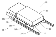
図2は、本発明の第1から第2の実施形態に関わる前記ウエハー試験ユニット20を示す斜視図であり、デバイス用電源と試験機能を搭載したテスター部26と、ロードボード16と、ユニットフレーム25と、前記ユニットスライド機構28と、図3で表示のプローブカード21、シール部材22、前記ウエハートレー23、真空チャンバー24、接続部材27を備えている。FIG. 2 is a perspective view showing the
前記ユニットスライド機構28は、
スライドユニット28bが組み込まれるリニアスライド機構28aと、前記スライドユニット28bをスライドさせる駆動機構28cと、前記リニアスライド機構28aと前記駆動機構28cが搭載されるフレーム部材28dと、駆動モーター28eとを備えている。The
A
前記スライドユニット28bは前記ユニットフレーム25に連結され、前記フレーム部材28dは図1に示すように前記装置フレーム11に設置されている。
これにより、前記駆動機構28cが駆動モーター28eで駆動されることで前記ウエハー試験ユニット20がスライドすることができる。The
As a result, the
前記ウエハー試験ユニット20は、前記テスター部26を搭載し、外部との接続を行う配線材料にロボットケーブルなどの可撓性のケーブルが使用されることで、該ウエハー試験ユニット20を容易にスライドさせることができる。 The
本図では、前記リニアスライド機構28aと前記スライドユニット28bと前記駆動機構28cと前記フレーム部材28dが組み込まれた一体型の直動スライドガイドユニットを使用している。
前記駆動機構28cにはボールネジが使用され、前記スライドユニット28bにはナットが組み込まれ、前記ボールネジの駆動で前記スライドユニット28bがスライドする機構になっている。In this figure, an integrated linear slide guide unit in which the
A ball screw is used for the
前記ユニットスライド機構28は、前記ウエハー試験ユニット20の両側に設置され、両側のモーターは同期して動作することで、重量の大きいユニットを高速、且つ低振動でスライドさせることができる。
なお、前記ウエハー試験ユニット20が軽量で、且つスライドする速度が低速の場合は片側に設置することも可能である。The
If the
図1で示すように、前記ウエハー試験ユニット20は前記装置フレーム11に積載され、前記ユニットスライド機構28により、前記ウエハー位置決めステージ32に相対するようにスライドすることができている。 As shown in FIG. 1, the
また図示は省略するが、前記駆動機構28cにリニアモーターが組み込まれたスライド機構を使用することも可能である。 Although not shown, it is also possible to use a slide mechanism in which a linear motor is incorporated in the
図3は、図2で示されるウエハー試験ユニット20の構成を示す下方から見た斜視図であり、前記ウエハー試験ユニット20が前方にスライドした状態を示し、前記テスター部26と、前記ロードボード16と、前記真空チャンバー24と、前記プローブカード21と、前記シール部材22と、前記ウエハートレー23と、前記ユニットフレーム25と、前記接続部材27と、前記ユニットスライド機構28と、を備えている。FIG. 3 is a perspective view showing the configuration of the
なお、前記ロードボード16と前期プローブカード21と前記真空チャンバー24、及び前期プローブカード21と前記ウエハートレー23と前記真空チャンバー24とで囲まれる二つの密閉空間の形成の説明は図7で行うので、ここでの説明は省略する。 The formation of two enclosed spaces surrounded by the
図4は、第3から第7の実施形態に関わる前記ウエハー位置決めステージ32を有する前記ウエハー位置決めユニット30の各部材の外観を示す斜視図であり、前記ユニット昇降機構31と、前記ウエハー位置決めステージ32と前記位置情報撮影機構33とを備え、前記ウエハー位置決めステージ32はウエハートレー載置面35を有したアライメントステージ34と、アライメントステージ揺動機構40と、アライメントステージ昇降機構50とを備えている。(詳細は図5で説明) FIG. 4 is a perspective view showing the appearance of each member of the
なお、前記ウエハー位置決めステージ32と前記位置情報撮影機構33は、昇降テーブル36に搭載され前記ユニット昇降機構31(詳細は省略)で昇降させることができる。
また、位置情報撮影機構33は上下面を撮影するカメラと照明を有している。The
Further, the position
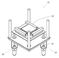
図5は、前記ウエハー位置決めステージ32を構成する部材の外観を示す斜視図であり、前記位置決めステージ32の構成を分りやすくするため、前記アライメントステージ34を上方に移動し、揺動機構取付け板44を下方に移動して表示し、前記アライメントステージ昇降機構50はアライメントステージ取付け板51を押し上げた状態を示している。 FIG. 5 is a perspective view showing the appearance of the members constituting the
前記ウエハー位置決めステージ32は、前記ウエハートレー載置面35を有しX方向とY方向と回転方向の位置制御を行う前記アライメントステージ34と、前記アライメントステージ揺動機構40と、前記アライメントステージ昇降機構50とを備えている。
図示は省略するが、前記ウエハートレー載置面35は前記ウエハートレー23を吸引保持する吸引口を有し、バキューム機構29(図示は省略)で吸引している。The
Although not shown, the wafer
前記アライメントステージ揺動機構40は、前記アライメントステージ昇降機構50を搭載する揺動板41と、前記真空チャンバー24の下面の四隅に接触する突き当て部材42と、球面滑り軸受45を中心位置に有し、前記球面滑り軸受45の外周部に放射状に複数のバネ部材46を有する前記揺動機構取付け板44を備えている。 The alignment
また前記揺動板41の中央部が前記球面滑り軸受45の可動部(ボールジョイントのボールに連結した部分)と連結され、前記揺動機構取付け板44の中央部が前記球面滑り軸受45の固定部と連結され、前記揺動板41と前記揺動機構取付け板44の間は、前記揺動板41の揺動スペースが確保されている。なお、本図では前記球面滑り軸受45にボールジョイントタイプの軸受を使用し、前記バネ部材46に板バネを使用している。 Further, the central portion of the
前記アライメントステージ昇降機構50は、前記揺動板41と、前記アライメントステージ取付け板51と、ボールネジ56と前記ボールネジ56でスライドする駆動機構スライド軸57と前記駆動機構スライド軸57と嵌合する駆動機構スライドユニット58とを有する駆動機構55と、前記ボールネジ56に連結した駆動モーター59と、スライド軸53とスライドユニット54を有するスライド機構52と、を備えている。なお、前記駆動モーター59は金具を介して前記揺動板41に設置されている。 The alignment
前記駆動機構55を構成する前記駆動機構スライドユニット58が1カ所、及び前記スライド機構52を構成する前記スライドユニット54が3カ所前記揺動板41の四隅に設置され、
前記駆動機構55を構成する前記駆動機構スライド軸57の先端が1カ所、及び前記スライド機構52を構成する前記スライド軸53の先端が3カ所前記アライメントステージ取付け板51の四隅に連結されている。前記駆動機構55が駆動されることで、前記アライメントステージ取付け板51が昇降する。The drive
The tip of the drive
前記駆動機構55が使われる数は図5では1カ所使用しているが、本発明の第6に記載のように前記アライメントステージ昇降機構50が搬送する重量と昇降する速さに応じて1カ所から4カ所まで選ぶことができる。 The number of the
図6は、前記駆動機構55を2カ所使用した前記ウエハー位置決めステージ32の斜視図であり、該ウエハー位置決めステージ32は、前記アライメントステージ34と、前記アライメントステージ揺動機構40と、前記アライメントステージ昇降機構50とを備え、2カ所の前記駆動モーター59が同期して駆動されることにより、前記アライメントステージ34の搬送荷重をより大きく、高速且つ低振動で昇降させることができる。 FIG. 6 is a perspective view of the
さらに本発明の第7の実施形態で記述しているように、前記駆動機構55にボールネジ一体型ボールスプラインが使用され、前記スライド機構52にボールスプラインが使用されることにより、前記駆動機構55と前記スライド機構52に市販製品を利用でき、前記アライメントステージ昇降機構50を容易に構築できると共に、前記アライメントステージ34を垂直に、高速且つ低振動で昇降させることができる。(図5も同様) Further, as described in the seventh embodiment of the present invention, a ball screw integrated ball spline is used for the
図7は、前記ユニット昇降機構31で前記ウエハー位置決めステージ32が押し上げられ、前記アライメントステージ揺動機構40を構成する揺動板41の上面の四隅に設けられた前記突き当て部材42が、前記ウエハー試験ユニット20を構成する前記真空チャンバー24の下面の四隅に接触した状態を示している。 In FIG. 7, the
この接触により、前記揺動板41は、前記真空チャンバー24との平行度が確保され、同時に前記アライメントステージ34も平行度が確保されている。なお、前記ウエハートレー23は前記真空チャンバー24に吸引されて該真空チャンバー24との平行度を保っていることから、前記ウエハートレー23と前記アライメントステージ34は、同じ傾きを持つことができている(平行度が得られている)。本図は、前記アライメントステージ昇降機構50が前記アライメントステージ34を最下点に停止させた状態を示している。 By this contact, the
なお、前記ウエハー試験ユニット20を構成する前記ロードボード16と前記プローブカード21の間、及び前記プローブカード21と前記ウエハー15が載置される前記ウエハートレー23の間を、真空圧で電気的に接続させるための第一の密閉空間24aと第二の密閉空間24bが、下記のように形成されている。 It should be noted that the space between the
前記ロードボード16と、シール部材22aと、前記真空チャンバー24と、シール部材22bと、前期プローブカード21と、で第一の密閉空間24aが形成され、前記真空チャンバー24と、前記シール部材22bと、前期プローブカード21と、前記シール部材22と、前記ウエハートレー23と、で第二の密閉空間24bが形成されている。The first sealed
前記第一の密閉空間24aを真空吸引することで、前記ロードボード16と前記プローブカード21間の電気的接続がポゴタワーなどの接続部材27を介して行われ、
前記第二の密閉空間24bを真空吸引することで、前記プローブカード21と前記ウエハー15間の電気的接続が行われる。
なお、前記バキューム機構29の圧力調整で密閉空間の減圧と大気圧への開放を行うことができる。By vacuum-sucking the first sealed
By vacuum-sucking the second sealed
By adjusting the pressure of the vacuum mechanism 29, the closed space can be depressurized and opened to the atmospheric pressure.
図8は、前記真空チャンバー24と平行度が確保された前記アライメントステージ34が、前記アライメントステージ昇降機構50により押し上げられ、前記真空チャンバー24に保持されている前記ウエハートレー23に接触した状態を示している。
図7と同様に、前記突き当て部材42は前記真空チャンバー24の下面に接触している。FIG. 8 shows a state in which the
Similar to FIG. 7, the abutting
図9は、前記真空チャンバー24に保持されている前記ウエハートレー23が、前記第二の密閉空間24bが前記バキューム機構29で圧力調整された後、前記真空チャンバー24から切り離され、前記アライメントステージ昇降機構50により、前記ウエハー15の載置と取出し、及び前記ウエハー15と前記プローブカード21の位置合せが行われる位置に移動した状態を示している。 In FIG. 9, the
前記ウエハー15と前記プローブカード21の位置合せが行われる時、前記位置情報撮影機構33が前記ウエハートレー23と前記プローブカード21の間に移動し位置情報を取得する。図7及び図8と同様に、前記突き当て部材42は前記真空チャンバー24の下面に接触している。 When the
これまで説明したように、前記アライメントステージ揺動機構40と前記アライメントステージ昇降機構50の機能により、前記ウエハー位置決めステージ32が前記ユニット昇降機構31で押し上げられ、前記揺動板41の上面の四隅に設けられた前記突き当て部材42が、前記真空チャンバー24の下面の四隅に接触することにより、前記真空チャンバー24の傾きに前記アライメントステージ34の傾きを追随させることができる。 As described above, by the functions of the alignment
次に、前記真空チャンバー24の傾きに追随した前記アライメントステージ34を、前記アライメントステージ昇降機構50で上昇させることにより、前記ウエハートレー23の傾きを変えることなく、該ウエハートレー23の下面に接触させることができる。なお、該ウエハートレー23の下面に接触する時、前記バキューム機構29により真空吸引が行われている。 Next, the
また、前記ウエハートレー23を前記ウエハー15の搭載と取出しと位置合せとが行われる位置へ下降させる工程と、前記ウエハー15と前記プローブカード21との位置合せが行われる工程と、前記ウエハートレー23を上昇させ前記プローブカード21との接触が行われる工程とにおいて、前記ウエハートレー23の傾きを変えることなく該ウエハートレー23を昇降させることができ、高精度の位置合せが可能になる。 Further, a step of lowering the
前記ウエハートレー23が前記真空チャンバー24に吸引保持されている位置から、前記ウエハー15が載置される位置までの移動距離は、前記位置情報撮影機構33による位置情報の撮影ができる高さとなり、前記突き当て部材42の高さで確保されている。 The moving distance from the position where the
なお、前記アライメントステージ昇降機構50を構成する前記駆動機構55には、ボールネジ一体型ボールスプラインが使用され、前記スライド機構52には、ボールスプラインが使用されている(本発明の第7の実施形態)。
このことにより、市販製品が使用可能なことと、前記ウエハートレーの垂直昇降、大きな荷重への対応、及び高速且つ低振動での昇降を行うことができる。A ball screw integrated ball spline is used for the
As a result, it is possible to use a commercially available product, to vertically raise and lower the wafer tray, to handle a large load, and to raise and lower the wafer tray at high speed and with low vibration.
図10は、本発明の第8の実施形態に係るウエハー試験ユニット20が搭載されたウエハー試験装置10の外観斜視図であり、ウエハートレー昇降機構60は前記ウエハー15が前記ウエハートレー23に載置される位置に降下し、前記ウエハー位置決めステージ32はその下側に待機している。FIG. 10 is an external perspective view of the
図11は、本発明の第8の実施形態に係るウエハー試験ユニット20で、前記ユニットスライド機構28に加え本発明の第9の実施形態に関わる前記ウエハートレー昇降機構60を搭載し、ウエハートレー保持板61と、前記ロードボード16と、前記ウエハートレー23と、前記ユニットフレーム25と、前記テスター部26と、図12で表示の前記真空チャンバー24と前記プローブカード21と前記シール材22と、前記接続部材27(図13)とを備えている。なお、前記ウエハートレー昇降機構60は前記ウエハー15を載置する位置に下降している。 FIG. 11 shows a
前記ユニットスライド機構28は、前記スライドユニット28bが組み込まれる前記リニアスライド機構28aと、前記スライドユニット28bをスライドさせる前記駆動機構28cと、前記リニアスライド機構28aと前記駆動機構28cが搭載される前記フレーム部材28dと、駆動モーター28eとを備えている。 The
なお前記ユニットスライド機構28は、本発明の第2の実施形態に係る前記ユニットスライド機構28を使用していることから、詳細の説明は省略する。 Since the
図12は、図11で示される前記ウエハー試験ユニット20を下方から見た斜視図であり、前記ロードボード16と前記ウエハートレー昇降機構60と、前記ウエハートレー23と、前記ユニットフレーム25と、前記テスター部26と、前記真空チャンバー24と、前記プローブカード21と、前記シール部材22を表示している。 FIG. 12 is a perspective view of the
詳しくは図17で説明するが前記ロードボード16と、前記真空チャンバー24と、前記プローブカード21で囲まれる空間、及び前記真空チャンバー24と、前記プローブカード21と、前記ウエハートレー23で囲まれる空間は、バキューム機構29(図示は省略)で減圧され、前記ウエハー15と前記プローブカード21の間の加圧接続が行われる。Although details will be described with reference to FIG. 17, a space surrounded by the
図13は、本発明の第9から第11の実施形態に関わる前記ウエハートレー昇降機構60を示す斜視図であり、該ウエハートレー昇降機構60は前記真空チャンバー24と、前記駆動機構55と前記スライド機構52と、前記ウエハートレー保持板61と、前記シール部材22と、前記シール部材22aと前記シール部材22bと、を備えている。理解を容易にするため、前記プローブカード21と前記ウエハートレー23も表示している。 FIG. 13 is a perspective view showing the wafer
前記駆動機構55は、ボールネジ56と、前記ボールネジ56の駆動でスライドする駆動機構スライド軸57と、前記駆動機構スライド軸57と嵌合する駆動機構スライドユニット58と、を備え、
前記スライド機構52はスライド軸53とスライドユニット54を備えている。
前記駆動機構55と前記スライド機構52は、図5で説明の駆動機構55及びスライド機構52と同じ機構が使用されている。The
The
The
また、前記駆動機構55は駆動モーター59の駆動で、前記駆動機構スライド軸57をスライドさせている。なお、前記駆動モーター59は前記ロードボード16の上から取付け金具を介して、前記真空チャンバー24に設置され、前記ウエハー試験ユニット20の高さを低くするため、ベルトで前記ボールネジ56を駆動する方式を採用している。Further, the
前記駆動機構55の駆動機構スライドユニット58と前記スライド機構52のスライドユニット54は、前記真空チャンバー24の四隅の斜めに対向する2カ所に設置され、前記駆動機構55の駆動機構スライド軸57の先端と、前記スライド機構52のスライド軸53の先端は、前記ウエハーウエハートレー保持板61の四隅の斜めに対向する2カ所に連結されている。The drive
また前記駆動機構の設置される数は、本発明の第10の実施形態で記述しているように、前記ウエハートレー保持板61に加わる荷重と昇降させる速度に応じて、1カ所から4カ所まで選ぶことができる。 Further, the number of the drive mechanisms installed is from 1 to 4 depending on the load applied to the wafer
さらに本発明の第11の実施形態で記述しているように、前記駆動機構55にボールネジ一体型ボールスプラインが使用され、前記スライド機構52にボールスプラインが使用されることにより、前記駆動機構55と前記スライド機構52に市販製品を利用でき、前記ウエハートレー昇降機構60を容易に構築できると共に、前記ウエハートレー保持板61を垂直に、高速且つ低振動で昇降させることができる。 Further, as described in the eleventh embodiment of the present invention, a ball screw integrated ball spline is used for the
なお、前記ロードボード16(可視化している)と前記プローブカード21の間を接続する接続部材27が表示され、前記真空チャンバー24の内側に配置されている。上記部材の位置関係は図17で説明を行う。 A connecting
図14は、図13の前記ウエハートレー昇降機構60を下方から見た斜視図であり、表示されている部材で前記プローブカード21と前記シール部材22以外は、すべて図13と同じであることから説明は省略し、前記シール部材22に関しては図17で説明を行う。 FIG. 14 is a perspective view of the wafer
図15は、本発明の第12の実施形態に係る前記ウエハー位置決めステージ32を有する前記ウエハー位置決めユニット30の各部材の外観を示す斜視図であり、前記ウエハー位置決めステージ32と前記位置情報撮影機構33は昇降テーブル36に搭載され、前記ユニット昇降機構31により昇降させることができる。 FIG. 15 is a perspective view showing the appearance of each member of the
図16は、本発明の第12の実施形態に係る前記ウエハー位置決めステージ32と前記位置情報撮影機構33の外観斜視図であり、前記ウエハー位置決めステージ32の構成を分りやすくするため、前記揺動板41から上の前記アライメントステージ34を上方に移動し、揺動機構取付け板44aを下方に移動して表示している。 FIG. 16 is an external perspective view of the
前記ウエハー位置決めステージ32は、前記ウエハートレー載置面35を有しX方向とY方向と回転方向の位置制御を行う前記アライメントステージ34と、前記アライメントステージ揺動機構40を備えている。図示は省略するが、前記ウエハートレー載置面35は前記ウエハートレー23を吸引保持する吸引口を有し、前記バキューム機構29で吸引している。 The
本発明の第13の実施形態に係る前記アライメントステージ揺動機構40は、前記アライメントステージ34を搭載する前記揺動板41と、前記ウエハートレー保持板61の下面の四隅に接触する突き当て部材42aと、前記球面滑り軸受45を中心位置に有し該球面滑り軸受45の外周部に放射状に複数の前記バネ部材46を有する前記揺動機構取付け板44aを備え、該揺動機構取付け板44aは前記昇降テーブル36に搭載されている。 The alignment
また前記揺動板41の中央部が前記球面滑り軸受45の可動部(ボールジョイントのボールに連結した部分)と連結され、前記揺動機構取付け板44aの中央部が前記球面滑り軸受45の固定部と連結され、前記揺動板41と前記揺動機構取付け板44aの間は、前記揺動板41の揺動スペースが確保されている。なお、本図では前記球面滑り軸受45にボールジョイントタイプの軸受を使用し、前記バネ部材46に板バネを使用している。 Further, the central portion of the
前記突き当て部材42aの高さは、前記ユニット昇降機構31の上昇で前記ウエハー位置決めステージ32が上昇し、該突き当て部材42aが前記ウエハーウエハートレー保持板61に接触した時、前記アライメントステージ34のウエハートレー載置面35が前記ウエハートレー23を数ミリメートル押し上げ、該ウエハートレー23が前後左右に移動できる高さを有している。この押上により前記ウエハー15と前期プローブカード21の位置合せを行うことができる。 The height of the abutting
図17は、本発明の第8の実施形態に関わる前記ウエハー試験ユニット20を構成する前記ロードボード16と、前記真空チャンバー24と、前記プローブカード21と、前記ウエハートレー23と、で囲まれる二つの密閉空間の形成を示す断面図である。17, the double of said
前記ウエハートレー昇降機構60の上昇(図の一点鎖線で示す部分)で、前記ロードボード16と、前記シール部材22aと、前記真空チャンバー24と、前記シール部材22bと、前期プローブカード21とで第一の密閉空間24aが形成され、
前記真空チャンバー24と、前記シール部材22bと、前期プローブカード21と、前記シール部材22と、前記ウエハートレー23とで第二の密閉空間24bが形成される。By ascending the wafer tray elevating mechanism 60 (the portion indicated by the alternate long and short dash line in the figure), the
A second sealed
前記第一の密閉空間24aを真空吸引することで、前記ロードボード16と前記プローブカード21間の電気的接続がポゴタワーなどの前記接続部材27を介して行われ、前記第二の密閉空間24bを真空吸引することで、前記プローブカード21と前記ウエハー15間の電気的接続が行われる。
なお、真空吸引は前記バキューム機構29で行われ、該バキューム機構29の圧力調整で密閉空間の減圧と加圧及び大気圧への開放が行われる。By vacuum-sucking the first
The vacuum suction is performed by the vacuum mechanism 29, and the pressure of the vacuum mechanism 29 is adjusted to reduce the pressure, pressurize, and open the closed space to atmospheric pressure.
図18は、本発明の第8の実施形態に係る前記ウエハー試験ユニット20で前記ウエハートレー昇降機構60が上昇し、前記ウエハートレー23に載置された前記ウエハー15と前記プローブカード21が接触した時の位置を示す概略図である(詳細は省略)。 In FIG. 18, the wafer
前記ウエハー位置決めステージ32はその下方に待機している。前記ウエハー位置決めステージ32は前記アライメントステージ34と前期アライメントステージ揺動機構40を備えている。 The
図19は、図18の状態から前記ウエハートレー昇降機構60が降下し、前記ウエハー15の前記ウエハートレー23への載置と取出しが行われる位置(最下点)に停止した状態を示している。 FIG. 19 shows a state in which the wafer
なお、前記ウエハー位置決めステージ32は下方に停止しており、前記突き当て部材42aは前記ウエハートレー保持板61と離れ、前記アライメントステージ揺動機構40は動作していない状態である。 The
図20は、図19の状態から前記ウエハー位置決めステージ32が前記ユニット昇降機構31で押し上げられ、前記突き当て部材42aは前期ウエハートレー保持板61に接触している。この接触と同時に前記アライメントステージ34の前記ウエハートレー載置面35は、前記ウエハートレー23に接触し数ミリメートル押し上げた状態になっている。 In FIG. 20, the
前記ウエハートレー23を数ミリメートル押し上げることで、前記アライメントステージ34は前記ウエハートレー23をX方向とY方向と回転方向の位置制御を行うことができ、前記位置情報撮影機構33を前記ウエハートレー23と前期プローブカード21の間に挿入させて、必要とする位置情報の取得と位置合せを行うことができる。 By pushing up the
図21は、本発明の第14の実施形態に係る前記ウエハー位置決めユニット30が搭載される前記ウエハー試験装置10の外観斜視図を示し、前記ウエハー試験ユニット20が搭載された前記装置フレーム11が2列配置された場合を示している。 FIG. 21 shows an external perspective view of the
前記ウエハー位置決めユニット30は、前記ウエハー位置決めステージ32と前記位置情報撮影機構33と前記ユニット昇降機構31と横方向ユニットスライド37機構を備え、前記横方向ユニットスライド機構37の移動で、2列の前記装置フレーム11に搭載された前記ウエハー試験ユニット20への対処を可能にしている。 The
前記横方向ユニットスライド機構37は、スライドガイド38aとスライドユニット38bを有するリアスライド機構38と、前記スライドユニット38bをスライドさせる駆動機構39と、前記リニアスライド機構38と前記駆動機構39が搭載されるフレーム部材37aとを備えている(詳細は省略する)。
前記ウエハー位置決めユニット30が前記横方向ユニットスライド機構37を備えることで、該ウエハー位置決めユニット30を列方向にスライドさせることができる。The lateral
When the
なお、前記駆動機構39にリニアモーターを使用した機構を採用することで、前記ウエハー位置決めユニット30を高速、且つ低振動でスライドさせることができる。 By adopting a mechanism using a linear motor for the
前記ウエハートレー昇降機構60を備えた前記ウエハー試験ユニット20が搭載された前記ウエハー試験装置10の場合、前記ウエハー位置決めステージ32の役割は、前記ウエハー15と前記プローブカード21の位置合せだけになるため、位置合せ終了後直ぐに次に予定される前記ウエハー試験ユニット20へ移動することができ、試験装置のコストを抑えて試験装置の稼働率をさらに向上することができる。In the case of the
本発明は以上のように構成するので、具体的には次の課題への対応が可能になる。
ウエハー試験ユニットにユニットスライド機構を設け、さらにウエハー位置決めステージに、アライメントステージ揺動機構とアライメントステージ昇降機構を設けることにより、
ウエハー試験ユニットの下側にウエハー位置決めステージのスペースを無くすことができ、ウエハートレーに載置されたウエハーとプローブカードの位置合せを行い、ウエハートレーを上昇させてウエハーの電極とプローブカードの端子を接触させる工程において、ウエハートレーの上昇による位置ズレを発生させることなく、ウエハーの電極とプローブカードの端子を高精度に接触させることができる。
また、ウエハー試験ユニットにユニットスライド機構とウエハートレー昇降機構を設ける方式の場合、ウエハー位置決めステージがウエハートレーを昇降させる工程を、ウエハー位置決めステージから切り離し、ウエハートレー昇降機構に行わせることができ、ウエハー位置決めステージには、ウエハーの位置合せの工程のみを行わせることで、ウエハーの電極とプローブカードの端子間の高精度の位置合せと、高稼働率のウエハー試験装置を提供することができる。
本方式の場合ウエハー試験ユニットのコストは高くなるデメリットもあるが、本発明の第14の実施形態に係るウエハー位置決めユニットを使用することで、高稼働率のウエハー試験装置が実現する。
さらに、本発明におけるウエハー試験装置は従来の多段構成の試験装置に比較し、より多くのウエハー試験ユニットの搭載を可能にすることから、一度に多数のウエハーの試験が要求されるウエハーレベルバーンイン試験などの試験装置として期待できる。Since the present invention is configured as described above, it is possible to specifically deal with the following problems.
By providing a unit slide mechanism in the wafer test unit and further providing an alignment stage swing mechanism and an alignment stage elevating mechanism in the wafer positioning stage.
The space of the wafer positioning stage can be eliminated under the wafer test unit, the wafer mounted on the wafer tray and the probe card are aligned, and the wafer tray is raised to connect the wafer electrodes and the probe card terminals. In the step of contacting, the electrodes of the wafer and the terminals of the probe card can be brought into contact with each other with high accuracy without causing a positional deviation due to the raising of the wafer tray.
Further, in the case of the method in which the unit slide mechanism and the wafer tray elevating mechanism are provided in the wafer test unit, the step of raising and lowering the wafer tray by the wafer positioning stage can be separated from the wafer positioning stage and caused by the wafer tray elevating mechanism to perform the wafer. By causing the positioning stage to perform only the wafer alignment step, it is possible to provide a highly accurate alignment between the wafer electrode and the terminal of the probe card and a wafer test apparatus having a high operating rate.
In the case of this method, there is a demerit that the cost of the wafer test unit is high, but by using the wafer positioning unit according to the 14th embodiment of the present invention, a wafer test apparatus having a high operating rate can be realized.
Further, since the wafer test apparatus in the present invention enables mounting of a larger number of wafer test units as compared with the conventional multi-stage test apparatus, a wafer level burn-in test that requires testing of a large number of wafers at one time is required. It can be expected as a test device such as.
10 ウエハー試験装置
11 装置フレーム
15 ウエハー
16 ロードボード
20 ウエハー試験ユニット
21 プローブカード
22 シール部材
22a シール部材
22b シール部材
23 ウエハートレー
24 真空チャンバー
24a 第一の密閉空間
24b 第二の密閉空間
25 ユニットフレーム
26 テスター部
27 接続部材
28 ユニットスライド機構
28a リニアスライド機構
28b スライドユニット
28c 駆動機構
28d フレーム部材
28e 駆動モーター
29 バキューム機構
30 ウエハー位置決めユニット
31 ユニット昇降機構
32 ウエハー位置決めステージ
33 位置情報撮影機構
34 アライメントステージ
35 ウエハートレー載置面
36 昇降テーブル
37 横方向ユニットスライド機構
37a フレーム部材
38 リニアスライド機構
38a スライドガイド
38b スライドユニット
39 駆動機構
40 アライメントステージ揺動機構
41 揺動板
42 突き当て部材
42a 突き当て部材
44 揺動機構取付け板
44a 揺動機構取付け板
45 球面滑り軸受
46 バネ部材
50 アライメントステージ昇降機構
51 アライメントステージ取付け板
52 スライド機構
53 スライド軸
54 スライドユニット
55 駆動機構
56 ボールネジ
57 駆動機構スライド軸
58 駆動機構スライドユニット
59 駆動モーター
60 ウエハートレー昇降機構
61 ウエハートレー保持板10
35 Wafer
Claims (8)
テスト回路等を搭載するロードボードと、前記プローブカードと、前記ウエハーを載置するウエハートレーと、前記ロードボードと前記プローブカードで挟まれる空間及び前記プローブカードと前記ウエハートレーで挟まれる空間の周囲を囲んで密閉空間を形成する真空チャンバーと、を有するウエハー試験ユニットと、
前記ウエハー試験ユニットの前面側に配置され、前記ウエハートレーを載置し前記ウエハーの電極と前記プローブカードの端子間の位置合せを行うウエハー位置決めステージと、カメラを有する位置情報撮影機構と、前記ウエハー位置決めステージと前記位置情報撮影機構を昇降させるユニット昇降機構と、を有するウエハー位置決めユニットと、
前記ウエハー試験ユニットを搭載する装置フレームと、
を備え、
前記ウエハー試験ユニットは、
前記プローブカードに相対するように前記真空チャンバーに保持されている前記ウエハートレーが、該ウエハー試験ユニットの前面側に配置された前記ウエハー位置決めステージに相対するように、該ウエハー試験ユニットをスライドさせるユニットスライド機構を備え、
前記ウエハー位置決めステージは、
スライドした前記ウエハー試験ユニットのウエハートレーに相対するように配置され、
X方向とY方向と回転方向の位置制御を行うアライメントステージと、
前記アライメントステージのウエハートレー載置面の傾きを、前記ウエハートレーの傾きに追随させるアライメントステージ揺動機構と、
前記ウエハートレーを、前記真空チャンバーに保持される位置と前記ウエハーが載置される位置との間を昇降させるアライメントステージ昇降機構と、
を備え、
前記アライメントステージ揺動機構は、
前記ウエハー試験ユニットがスライドし前記ウエハー位置決めステージが前記ユニット昇降機構で押し上げられる時、前記真空チャンバーの下面の四隅に接触する突き当て部材と、
前記突き当て部材を有する揺動板と、
可動部と固定部を有する球面滑り軸受と、
前記突き当て部材が前記真空チャンバーに接触した時、前記揺動板の外周部に加わる荷重を支えるバネ部材と、
前記揺動板の下側に該揺動板が揺動するスペースを保って設置される揺動機構取付け板と、
を備え、
前記突き当て部材は、
前記真空チャンバーに接触した時、前記位置情報撮影機構が前記ウエハートレーと前記プローブカードの間に挿入され、前記ウエハーの電極と前記プローブカードの端子の位置情報を取得できる高さを有し、
前記球面滑り軸受は、
前記揺動板と前記揺動機構取付け板の間の中央部に設置され、
前記バネ部材は、
前記球面滑り軸受の外周部に複数配置されることを特徴とするウエハー試験装置。 This is a wafer test device that conducts tests by pressurizing and contacting the electrodes of the wafer and the terminals of the probe card with vacuum pressure.
Around a load board on which a test circuit or the like is mounted, a probe card, a wafer tray on which the wafer is placed, a space sandwiched between the load board and the probe card, and a space sandwiched between the probe card and the wafer tray. A wafer test unit with a vacuum chamber that surrounds and forms an enclosed space,
A wafer positioning stage arranged on the front side of the wafer test unit, on which the wafer tray is placed, and positioning between the electrodes of the wafer and the terminals of the probe card, a position information photographing mechanism having a camera, and the wafer. A wafer positioning unit having a positioning stage and a unit elevating mechanism for raising and lowering the position information photographing mechanism, and
An apparatus frame on which the wafer test unit is mounted and
With
The wafer test unit is
A unit that slides the wafer test unit so that the wafer tray held in the vacuum chamber so as to face the probe card faces the wafer positioning stage arranged on the front side of the wafer test unit. Equipped with a slide mechanism
The wafer positioning stage is
Arranged so as to face the wafer tray of the sliding wafer test unit.
An alignment stage that controls the positions in the X, Y, and rotation directions,
An alignment stage swing mechanism that makes the inclination of the wafer tray mounting surface of the alignment stage follow the inclination of the wafer tray.
An alignment stage elevating mechanism that elevates and elevates the wafer tray between the position held in the vacuum chamber and the position on which the wafer is placed.
With
The alignment stage swing mechanism is
When the wafer test unit slides and the wafer positioning stage is pushed up by the unit elevating mechanism, the abutting members that come into contact with the four corners of the lower surface of the vacuum chamber and
A rocking plate having the abutting member and
Spherical plain bearings with moving and fixed parts,
A spring member that supports a load applied to the outer peripheral portion of the rocking plate when the abutting member comes into contact with the vacuum chamber, and a spring member.
An oscillating mechanism mounting plate installed under the oscillating plate while maintaining a space for the oscillating plate to oscillate.
With
The abutting member is
When in contact with the vacuum chamber, the position information photographing mechanism is inserted between the wafer tray and the probe card, and has a height capable of acquiring position information of the electrodes of the wafer and the terminals of the probe card.
The spherical plain bearing is
It is installed in the central part between the rocking plate and the rocking mechanism mounting plate, and is installed.
The spring member is
A wafer test apparatus characterized in that a plurality of wafer test devices are arranged on the outer peripheral portion of the spherical slide bearing.
テスト回路等を搭載するロードボードと、前記プローブカードと、前記ウエハーを載置するウエハートレーと、前記ロードボードと前記プローブカードで挟まれる空間及び前記プローブカードと前記ウエハートレーで挟まれる空間の周囲を囲んで密閉空間を形成する真空チャンバーと、を有するウエハー試験ユニットと、
前記ウエハー試験ユニットの前面側に配置され、前記ウエハートレーを載置し前記ウエハーの電極と前記プローブカードの端子間の位置合せを行うウエハー位置決めステージと、カメラを有する位置情報撮影機構と、前記ウエハー位置決めステージと前記位置情報撮影機構を昇降させるユニット昇降機構と、を有するウエハー位置決めユニットと、
前記ウエハー試験ユニットを搭載する装置フレームと、
を備え、
前記ウエハー試験ユニットは、
前記プローブカードに相対するように前記真空チャンバーに保持されている前記ウエハートレーが、該ウエハー試験ユニットの前面側に配置された前記ウエハー位置決めステージに相対するように、該ウエハー試験ユニットをスライドさせるユニットスライド機構を備え、
前記ウエハー位置決めステージは、
スライドした前記ウエハー試験ユニットのウエハートレーに相対するように配置され、
X方向とY方向と回転方向の位置制御を行うアライメントステージと、
前記アライメントステージのウエハートレー載置面の傾きを、前記ウエハートレーの傾きに追随させるアライメントステージ揺動機構と、
前記ウエハートレーを、前記真空チャンバーに保持される位置と前記ウエハーが載置される位置との間を昇降させるアライメントステージ昇降機構と、
を備え、
前記アライメントステージ昇降機構は、
前記アライメントステージ揺動機構に設けられ、前記ウエハー試験ユニットがスライドし前記ウエハー位置決めステージが前記ユニット昇降機構で押し上げられる時、前記真空チャンバーの下面の四隅に接触する突き当て部材を有する揺動板と、
前記アライメントステージを搭載するアライメントステージ取付け板と、
ボールネジと、前記ボールネジの駆動でスライドする駆動機構スライド軸と、
前記駆動機構スライド軸と嵌合する駆動機構スライドユニットと、を有する駆動機構と、
前記駆動機構を駆動する駆動モーターと、
スライド軸とスライドユニットを有するスライド機構と、
を備え、
前記駆動機構は、
前記駆動機構スライドユニットが、前記揺動板の四隅の所要の箇所に設置され、前記駆動機構スライド軸の先端が、前記アライメントステージ取付け板の四隅の前記駆動機構スライドユニットが設置される箇所と相対する箇所に連結され、
前記ボールネジが前記揺動板に設置された前記駆動モーターに連結され、
前記スライド機構は、
前記スライドユニットが、前記揺動板の四隅の前記駆動機構スライドユニットが設置されない箇所に設置され、
前記スライド軸の先端が、前記アライメントステージ取付け板の四隅の前記スライドユニットが設置される箇所と相対する箇所に連結されることを特徴とするウエハー試験装置。This is a wafer test device that conducts tests by pressurizing and contacting the electrodes of the wafer and the terminals of the probe card with vacuum pressure.
Around a load board on which a test circuit or the like is mounted, a probe card, a wafer tray on which the wafer is placed, a space sandwiched between the load board and the probe card, and a space sandwiched between the probe card and the wafer tray. A wafer test unit with a vacuum chamber that surrounds and forms an enclosed space,
A wafer positioning stage arranged on the front side of the wafer test unit, on which the wafer tray is placed, and positioning between the electrodes of the wafer and the terminals of the probe card, a position information photographing mechanism having a camera, and the wafer. A wafer positioning unit having a positioning stage and a unit elevating mechanism for raising and lowering the position information photographing mechanism, and
An apparatus frame on which the wafer test unit is mounted and
With
The wafer test unit is
A unit that slides the wafer test unit so that the wafer tray held in the vacuum chamber so as to face the probe card faces the wafer positioning stage arranged on the front side of the wafer test unit. Equipped with a slide mechanism
The wafer positioning stage is
Arranged so as to face the wafer tray of the sliding wafer test unit.
An alignment stage that controls the positions in the X, Y, and rotation directions,
An alignment stage swing mechanism that makes the inclination of the wafer tray mounting surface of the alignment stage follow the inclination of the wafer tray.
An alignment stage elevating mechanism that elevates and elevates the wafer tray between the position held in the vacuum chamber and the position on which the wafer is placed.
With
The alignment stage elevating mechanism is
A rocking plate provided in the alignment stage swing mechanism and having abutting members that come into contact with the four corners of the lower surface of the vacuum chamber when the wafer test unit slides and the wafer positioning stage is pushed up by the unit elevating mechanism. ,
An alignment stage mounting plate on which the alignment stage is mounted and an alignment stage mounting plate
A ball screw, a drive mechanism slide shaft that slides by driving the ball screw, and
A drive mechanism having a drive mechanism slide unit that fits with the drive mechanism slide shaft, and
The drive motor that drives the drive mechanism and
A slide mechanism with a slide shaft and a slide unit,
With
The drive mechanism
The drive mechanism slide units are installed at required locations at the four corners of the rocking plate, and the tips of the drive mechanism slide shafts are relative to the locations where the drive mechanism slide units are installed at the four corners of the alignment stage mounting plate. It is connected to the place where you want to
The ball screw is connected to the drive motor installed on the rocking plate, and the ball screw is connected to the drive motor.
The slide mechanism
The slide unit is installed at four corners of the rocking plate where the drive mechanism slide unit is not installed.
A wafer test apparatus characterized in that the tips of the slide shafts are connected to locations facing the locations where the slide units are installed at the four corners of the alignment stage mounting plate .
前記駆動機構にボールネジ一体型ボールスプラインが使用され、
前記スライド機構にボールスプラインが使用されることを特徴とする請求項2または3に記載のウエハー試験装置。The alignment stage elevating mechanism is
A ball spline with an integrated ball screw is used for the drive mechanism.
The wafer test apparatus according to claim 2 or 3, wherein a ball spline is used for the slide mechanism.
テスト回路等を搭載するロードボードと、前記プローブカードと、前記ウエハーを載置するウエハートレーと、前記ロードボードと前記プローブカードで挟まれる空間及び前記プローブカードと前記ウエハートレーで挟まれる空間の周囲を囲んで密閉空間を形成する真空チャンバーと、を有するウエハー試験ユニットと、
前記ウエハー試験ユニットの前面側に配置され、前記ウエハートレーを載置し前記ウエハーの電極と前記プローブカードの端子間の位置合せを行うウエハー位置決めステージと、カメラを有する位置情報撮影機構と、前記ウエハー位置決めステージと前記位置情報撮影機構を昇降させるユニット昇降機構と、を有するウエハー位置決めユニットと、
前記ウエハー試験ユニットを搭載する装置フレームと、
を備え、
前記ウエハー試験ユニットは、
前記プローブカードに相対するように前記真空チャンバーに保持されている前記ウエハートレーが、該ウエハー試験ユニットの前面側に配置された前記ウエハー位置決めステージに相対するように、該ウエハー試験ユニットをスライドさせるユニットスライド機構と、
前記ウエハートレーを、前記真空チャンバーに保持される位置と前記ウエハーが載置される位置との間を昇降させるウエハートレー昇降機構を備え、
前記ウエハートレー昇降機構は、
前記真空チャンバーと、
前記ウエハートレーを載置するウエハートレー保持板と、
ボールネジと、前記ボ−ルネジの駆動でスライドする駆動機構スライド軸と、
前記駆動機構スライド軸と嵌合する駆動機構スライドユニットと、を有する駆動機構と、
ボールネジを駆動する駆動モーターと、
スライド軸とスライドユニットを有するスライド機構と、
を備え、
前記駆動機構は、
前記駆動機構スライドユニットが、前記真空チャンバーの四隅の所要の箇所に設置され、
前記駆動機構スライド軸の先端が、前記ウエハートレー保持板の四隅の前記駆動機構スライドユニットが設置される箇所と相対する箇所に連結され、
前記ボールネジが前記真空チャンバーに設置された前記駆動モーターに連結され、
前記スライド機構は、
前記スライドユニットが、前記真空チャンバーの四隅の前記駆動機構スライドユニットが設置されない箇所に設置され、
前記スライド軸の先端が、前記ウエハートレー保持板の四隅の前記スライドユニットが設置される箇所と相対する箇所に連結されることを特徴とするウエハー試験装置。This is a wafer test device that conducts tests by pressurizing and contacting the electrodes of the wafer and the terminals of the probe card with vacuum pressure.
Around a load board on which a test circuit or the like is mounted, a probe card, a wafer tray on which the wafer is placed, a space sandwiched between the load board and the probe card, and a space sandwiched between the probe card and the wafer tray. A wafer test unit with a vacuum chamber that surrounds and forms an enclosed space,
A wafer positioning stage arranged on the front side of the wafer test unit, on which the wafer tray is placed, and positioning between the electrodes of the wafer and the terminals of the probe card, a position information photographing mechanism having a camera, and the wafer. A wafer positioning unit having a positioning stage and a unit elevating mechanism for raising and lowering the position information photographing mechanism, and
An apparatus frame on which the wafer test unit is mounted and
With
The wafer test unit is
A unit that slides the wafer test unit so that the wafer tray held in the vacuum chamber so as to face the probe card faces the wafer positioning stage arranged on the front side of the wafer test unit. and the slide mechanism,
A wafer tray elevating mechanism for raising and lowering the wafer tray between a position held in the vacuum chamber and a position on which the wafer is placed is provided.
The wafer tray elevating mechanism is
With the vacuum chamber
A wafer tray holding plate on which the wafer tray is placed and a wafer tray holding plate
A ball screw, a drive mechanism slide shaft that slides by driving the ball screw, and
A drive mechanism having a drive mechanism slide unit that fits with the drive mechanism slide shaft, and
The drive motor that drives the ball screw and
A slide mechanism with a slide shaft and a slide unit,
With
The drive mechanism
The drive mechanism slide unit is installed at required locations at the four corners of the vacuum chamber.
The tips of the drive mechanism slide shafts are connected to the four corners of the wafer tray holding plate facing the locations where the drive mechanism slide units are installed.
The ball screw is connected to the drive motor installed in the vacuum chamber, and the ball screw is connected to the drive motor.
The slide mechanism
The slide unit is installed at four corners of the vacuum chamber where the drive mechanism slide unit is not installed.
A wafer test apparatus characterized in that the tips of the slide shafts are connected to locations facing the locations where the slide units are installed at the four corners of the wafer tray holding plate .
1乃至4カ所のいずれかであり、2カ所設置の場合は四隅の斜めに対向する2カ所に設置されることを特徴とする請求項5に記載のウエハー試験装置。 The required location where the drive mechanism of the wafer tray elevating mechanism is installed is
The wafer test apparatus according to claim 5, wherein the wafer test apparatus is installed at any of 1 to 4 locations, and in the case of 2 locations, the wafers are installed at two diagonally opposite locations at the four corners.
前記駆動機構にボールネジ一体型ボールスプラインが使用され、
前記スライド機構にボールスプラインが使用されることを特徴とする請求項5または6に記載のウエハー試験装置。The wafer tray elevating mechanism is
A ball spline with an integrated ball screw is used for the drive mechanism.
The wafer test apparatus according to claim 5 or 6, wherein a ball spline is used for the slide mechanism.
スライドした前記ウエハー試験ユニットのウエハートレーに相対するように配置され、
X方向とY方向と回転方向の位置制御を行うアライメントステージと、
前記アライメントステージのウエハートレー載置面の傾きを前記ウエハートレーの傾きに追随させるアライメントステージ揺動機構と、
を備え、
前記アライメントステージ揺動機構は、
前記ウエハー試験ユニットがスライドし前記ウエハー位置決めステージが前記ユニット昇降機構で押し上げられる時、前記ウエハートレー保持板の下面の四隅に接触する突き当て部材と、
前記突き当て部材を有する揺動板と、
可動部と固定部を有する球面滑り軸受と、
前記突き当て部材が前記ウエハートレー保持板に接触した時、前記揺動板の外周部に加わる荷重を支えるバネ部材と、
前記揺動板の下側に該揺動板が揺動するスペースを保って設置される揺動機構取付け板と、
を備え、
前記突き当て部材は、
前記ウエハートレー保持板に接触した時、前記アライメントステージが前記ウエハートレーを押し上げて位置制御が行える高さを有し、
前記球面滑り軸受は、
前記揺動板と前記揺動機構取付け板の間の中央部に設置され、
前記バネ部材は、
前記球面滑り軸受が設置される外周部に複数配置されることを特徴とする請求項5に記載のウエハー試験装置。The wafer positioning stage is
Arranged so as to face the wafer tray of the sliding wafer test unit.
An alignment stage that controls the positions in the X, Y, and rotation directions,
An alignment stage swing mechanism that makes the inclination of the wafer tray mounting surface of the alignment stage follow the inclination of the wafer tray, and
With
The alignment stage swing mechanism is
When the wafer test unit slides and the wafer positioning stage is pushed up by the unit elevating mechanism, abutting members that come into contact with the four corners of the lower surface of the wafer tray holding plate and
A rocking plate having the abutting member and
Spherical plain bearings with moving and fixed parts,
A spring member that supports a load applied to the outer peripheral portion of the rocking plate when the abutting member comes into contact with the wafer tray holding plate.
An oscillating mechanism mounting plate installed under the oscillating plate while maintaining a space for the oscillating plate to oscillate.
With
The abutting member is
The alignment stage has a height at which the position can be controlled by pushing up the wafer tray when it comes into contact with the wafer tray holding plate.
The spherical plain bearing is
It is installed in the central part between the rocking plate and the rocking mechanism mounting plate, and is installed.
The spring member is
The wafer test apparatus according to claim 5, wherein a plurality of the spherical slide bearings are arranged on the outer peripheral portion where the spherical slide bearings are installed .
Applications Claiming Priority (2)
| Application Number | Priority Date | Filing Date | Title |
|---|---|---|---|
| JP2019130610 | 2019-06-26 | ||
| JP2019130610 | 2019-06-26 |
Publications (3)
| Publication Number | Publication Date |
|---|---|
| JP2021005700A JP2021005700A (en) | 2021-01-14 |
| JP2021005700A5 JP2021005700A5 (en) | 2021-02-25 |
| JP6906128B2 true JP6906128B2 (en) | 2021-07-21 |
Family
ID=74060838
Family Applications (1)
| Application Number | Title | Priority Date | Filing Date |
|---|---|---|---|
| JP2020093761A Active JP6906128B2 (en) | 2019-06-26 | 2020-04-24 | Wafer test equipment |
Country Status (2)
| Country | Link |
|---|---|
| JP (1) | JP6906128B2 (en) |
| WO (1) | WO2020261949A1 (en) |
Families Citing this family (1)
| Publication number | Priority date | Publication date | Assignee | Title |
|---|---|---|---|---|
| CN114054385B (en) * | 2021-11-11 | 2024-02-09 | 四川和恩泰半导体有限公司 | Full-automatic double-head wafer tester |
Family Cites Families (4)
| Publication number | Priority date | Publication date | Assignee | Title |
|---|---|---|---|---|
| JP6267928B2 (en) * | 2013-10-29 | 2018-01-24 | 東京エレクトロン株式会社 | Maintenance inspection carriage for wafer inspection apparatus and maintenance method for wafer inspection apparatus |
| JP6515007B2 (en) * | 2015-09-30 | 2019-05-15 | 東京エレクトロン株式会社 | Wafer inspection method and wafer inspection apparatus |
| KR102367037B1 (en) * | 2017-06-21 | 2022-02-24 | 도쿄엘렉트론가부시키가이샤 | inspection system |
| JP6956030B2 (en) * | 2018-02-28 | 2021-10-27 | 東京エレクトロン株式会社 | Inspection system |
-
2020
- 2020-04-24 JP JP2020093761A patent/JP6906128B2/en active Active
- 2020-06-01 WO PCT/JP2020/022452 patent/WO2020261949A1/en active Application Filing
Also Published As
| Publication number | Publication date |
|---|---|
| WO2020261949A1 (en) | 2020-12-30 |
| JP2021005700A (en) | 2021-01-14 |
Similar Documents
| Publication | Publication Date | Title |
|---|---|---|
| JP4457180B1 (en) | Wafer tray and test equipment | |
| US6879180B2 (en) | Display panel inspection apparatus and inspection method | |
| JP2010204096A (en) | Testing apparatus and testing method | |
| KR102361259B1 (en) | Wafer test apparatus | |
| KR20200138002A (en) | Positioning mechanism and positioning method | |
| JP6471401B1 (en) | Semiconductor wafer test unit | |
| JP6906128B2 (en) | Wafer test equipment | |
| CN110211889B (en) | Inspection system | |
| JP5161975B2 (en) | Connector attaching / detaching device and test head | |
| JP2009539112A (en) | Small prober for TFT-LCD inspection | |
| TWI613452B (en) | Electronic component conveying device and electronic component inspection device | |
| JP4398513B1 (en) | Wiring board unit and test apparatus | |
| JP2021118344A (en) | Wafer test device | |
| KR101354690B1 (en) | Pannel moving device for touch screen pannel producing apparatus | |
| JP4482707B1 (en) | Test equipment | |
| JP2021136425A (en) | Wafer test device | |
| KR20030040913A (en) | Mounting and Separating Device from Test Tray in Handler for Testing Semiconductor Devices | |
| KR100897846B1 (en) | Substrate positioning device | |
| JP2017161326A (en) | Electronic component conveying apparatus and electronic component inspection apparatus | |
| JP2018148060A (en) | Test equipment of wafer level package | |
| KR102295435B1 (en) | The align of the device having micro pitch and testing device and align method of device | |
| KR102297834B1 (en) | Rotational stage apparatus for inspecting a large scale panel | |
| KR100536474B1 (en) | Picker for transferring devices in semiconductor test handler | |
| TW202213565A (en) | Testing apparatus and testing method | |
| TW202331871A (en) | Stage, testing apparatus, and stage operating method |
Legal Events
| Date | Code | Title | Description |
|---|---|---|---|
| A521 | Written amendment |
Free format text: JAPANESE INTERMEDIATE CODE: A523 Effective date: 20200514 |
|
| A621 | Written request for application examination |
Free format text: JAPANESE INTERMEDIATE CODE: A621 Effective date: 20200701 |
|
| A871 | Explanation of circumstances concerning accelerated examination |
Free format text: JAPANESE INTERMEDIATE CODE: A871 Effective date: 20201127 |
|
| A521 | Written amendment |
Free format text: JAPANESE INTERMEDIATE CODE: A523 Effective date: 20201127 |
|
| A975 | Report on accelerated examination |
Free format text: JAPANESE INTERMEDIATE CODE: A971005 Effective date: 20210107 |
|
| A131 | Notification of reasons for refusal |
Free format text: JAPANESE INTERMEDIATE CODE: A131 Effective date: 20210202 |
|
| A521 | Written amendment |
Free format text: JAPANESE INTERMEDIATE CODE: A523 Effective date: 20210219 |
|
| TRDD | Decision of grant or rejection written | ||
| A01 | Written decision to grant a patent or to grant a registration (utility model) |
Free format text: JAPANESE INTERMEDIATE CODE: A01 Effective date: 20210511 |
|
| A61 | First payment of annual fees (during grant procedure) |
Free format text: JAPANESE INTERMEDIATE CODE: A61 Effective date: 20210519 |
|
| R150 | Certificate of patent or registration of utility model |
Ref document number: 6906128 Country of ref document: JP Free format text: JAPANESE INTERMEDIATE CODE: R150 |