JP6897937B2 - Flexible printed wiring board manufacturing method, plate jigs, flexible printed wiring board piece handling tools, and flexible printed wiring board manufacturing equipment - Google Patents
Flexible printed wiring board manufacturing method, plate jigs, flexible printed wiring board piece handling tools, and flexible printed wiring board manufacturing equipment Download PDFInfo
- Publication number
- JP6897937B2 JP6897937B2 JP2018551064A JP2018551064A JP6897937B2 JP 6897937 B2 JP6897937 B2 JP 6897937B2 JP 2018551064 A JP2018551064 A JP 2018551064A JP 2018551064 A JP2018551064 A JP 2018551064A JP 6897937 B2 JP6897937 B2 JP 6897937B2
- Authority
- JP
- Japan
- Prior art keywords
- printed wiring
- wiring board
- flexible printed
- plate
- tray
- Prior art date
- Legal status (The legal status is an assumption and is not a legal conclusion. Google has not performed a legal analysis and makes no representation as to the accuracy of the status listed.)
- Active
Links
- 238000004519 manufacturing process Methods 0.000 title claims description 39
- 238000000034 method Methods 0.000 claims description 38
- 238000000926 separation method Methods 0.000 claims description 6
- 230000008569 process Effects 0.000 description 14
- 238000004080 punching Methods 0.000 description 8
- 230000004308 accommodation Effects 0.000 description 1
- 230000008901 benefit Effects 0.000 description 1
- 230000000694 effects Effects 0.000 description 1
- 238000005530 etching Methods 0.000 description 1
- 238000003754 machining Methods 0.000 description 1
- 239000000463 material Substances 0.000 description 1
- 230000007246 mechanism Effects 0.000 description 1
- 239000002184 metal Substances 0.000 description 1
- 238000012986 modification Methods 0.000 description 1
- 230000004048 modification Effects 0.000 description 1
- 238000003860 storage Methods 0.000 description 1
- 230000032258 transport Effects 0.000 description 1
Images


Classifications
-
- H—ELECTRICITY
- H05—ELECTRIC TECHNIQUES NOT OTHERWISE PROVIDED FOR
- H05K—PRINTED CIRCUITS; CASINGS OR CONSTRUCTIONAL DETAILS OF ELECTRIC APPARATUS; MANUFACTURE OF ASSEMBLAGES OF ELECTRICAL COMPONENTS
- H05K1/00—Printed circuits
- H05K1/02—Details
-
- H—ELECTRICITY
- H05—ELECTRIC TECHNIQUES NOT OTHERWISE PROVIDED FOR
- H05K—PRINTED CIRCUITS; CASINGS OR CONSTRUCTIONAL DETAILS OF ELECTRIC APPARATUS; MANUFACTURE OF ASSEMBLAGES OF ELECTRICAL COMPONENTS
- H05K3/00—Apparatus or processes for manufacturing printed circuits
Landscapes
- Engineering & Computer Science (AREA)
- Microelectronics & Electronic Packaging (AREA)
- Manufacturing & Machinery (AREA)
- Supply And Installment Of Electrical Components (AREA)
- Manufacturing Of Printed Wiring (AREA)
- Screen Printers (AREA)
Description
本発明は、フレキシブルプリント配線板の製造方法、板状治具、フレキシブルプリント配線板個片のハンドリング用具及びフレキシブルプリント配線板の製造設備に関する。
本出願は、2016年11月17日出願の日本出願第2016−224140号に基づく優先権を主張し、前記日本出願に記載された全ての記載内容を援用するものである。The present invention relates to a method for manufacturing a flexible printed wiring board, a plate jig, a tool for handling individual pieces of the flexible printed wiring board, and a manufacturing facility for the flexible printed wiring board.
This application claims priority based on Japanese Application No. 2016-224140 filed on November 17, 2016, and incorporates all the contents described in the Japanese application.
電子機器には、フレキシブルプリント配線板が使用されることが少なくない。近年の電子機器の小型化に伴って、電子機器内部に小型のフレキシブルプリント配線板が用いられることが多くなっている。 Flexible printed wiring boards are often used in electronic devices. With the recent miniaturization of electronic devices, small flexible printed wiring boards are often used inside electronic devices.
このようなフレキシブルプリント配線板は、大判のベースフィルム上に所望のフレキシブルプリント配線板の導電パターンを複数配列して形成し、パンチ加工によって個々のフレキシブルプリント配線板を打ち抜くことで、複数同時に製造することができる(特開平6−132618号公報参照)。 Such a flexible printed wiring board is manufactured by arranging a plurality of conductive patterns of a desired flexible printed wiring board on a large-sized base film and punching each flexible printed wiring board by punching to simultaneously manufacture a plurality of such flexible printed wiring boards. (See JP-A-6-132618).
なお、本明細書では、打ち抜かれる個々のフレキシブルプリント配線板をフレキシブルプリント配線板個片と呼び、ベースフィルム上に複数のフレキシブルプリント配線板個片の導電パターンが形成されたものをフレキシブルプリント配線板シートと呼ぶ。 In this specification, each flexible printed wiring board to be punched is referred to as a flexible printed wiring board piece, and a flexible printed wiring board having a conductive pattern of a plurality of flexible printed wiring board pieces formed on a base film is called a flexible printed wiring board piece. Called a sheet.
本発明の一態様に係るフレキシブルプリント配線板の製造方法は、はね出しのための板状治具が配置されるダイとこのダイに対応するパンチとを用い、1枚のフレキシブルプリント配線板シートから複数のフレキシブルプリント配線板個片を切り離す切り離し工程と、上記板状治具を持ち上げることにより複数のフレキシブルプリント配線板個片をはね出すはね出し工程と、上記複数のフレキシブルプリント配線板個片を位置決めする保持構造を有するトレーに、はね出した上記複数のフレキシブルプリント配線板個片を移載する移載工程とを備えるフレキシブルプリント配線板の製造方法であって、上記板状治具が、複数のフレキシブルプリント配線板個片の平面方向の移動を防止する複数のガイドと、この複数のガイドにより位置決めされる複数のフレキシブルプリント配線板個片を上記トレーの保持構造に正対するよう上記トレーに対して位置決めする位置決め部とを有し、上記移載工程が、上記板状治具に上記トレーを重ね合わせる重ね合わせ工程と、上記板状治具及びトレーを上下反転させる反転工程とを有する。 The method for manufacturing a flexible printed wiring board according to one aspect of the present invention uses a die on which a plate-shaped jig for projecting is arranged and a punch corresponding to the die, and one flexible printed wiring board sheet. A separation step of separating a plurality of flexible printed wiring board pieces from the above, a splashing process of ejecting a plurality of flexible printed wiring board pieces by lifting the plate-shaped jig, and the plurality of flexible printed wiring board pieces. A method for manufacturing a flexible printed wiring board, which comprises a transfer step of transferring a plurality of the plurality of flexible printed wiring board pieces that have been ejected to a tray having a holding structure for positioning the pieces. However, the plurality of guides for preventing the movement of the plurality of flexible printed wiring board pieces in the plane direction and the plurality of flexible printed wiring board pieces positioned by the plurality of guides face the holding structure of the tray. It has a positioning unit for positioning with respect to the tray, and the transfer step includes a stacking step of stacking the tray on the plate-shaped jig and an inversion step of flipping the plate-shaped jig and the tray upside down. Have.
また、本発明の別の態様に係る板状治具は、ダイ及びパンチを用いて1枚のフレキシブルプリント配線板シートから切り離される複数のフレキシブルプリント配線板個片を、ダイからはね出すために用いられる板状治具であって、上記複数のフレキシブルプリント配線板個片の平面方向の移動を防止する複数のガイドと、上記複数のフレキシブルプリント配線板個片を保持するトレーに対して位置決めする位置決め部とを備える。 Further, the plate-shaped jig according to another aspect of the present invention is for ejecting a plurality of flexible printed wiring board pieces separated from one flexible printed wiring board sheet from the die by using a die and a punch. It is a plate-shaped jig used, and is positioned with respect to a plurality of guides for preventing the movement of the plurality of flexible printed wiring board pieces in the plane direction and a tray for holding the plurality of flexible printed wiring board pieces. It is provided with a positioning unit.
[本発明が解決しようとする課題]
上記公報に開示される方法によってフレキシブルプリント配線板シートから複数のフレキシブルプリント配線板個片を打ち抜くと、ダイに複数のフレキシブルプリント配線板個片が残される。これら複数のフレキシブルプリント配線板個片は、ダイから一つ一つ取り上げられて、次工程に送られる。[Problems to be Solved by the Present Invention]
When a plurality of flexible printed wiring board pieces are punched out from the flexible printed wiring board sheet by the method disclosed in the above publication, a plurality of flexible printed wiring board pieces are left on the die. These plurality of flexible printed wiring board pieces are picked up one by one from the die and sent to the next process.
フレキシブルプリント配線板個片を大量に生産する場合は、複数のフレキシブルプリント配線板個片を取り上げて次工程に搬送する装置を設置することができるが、フレキシブルプリント配線板個片の製造量が十分に大きくない場合には、オペレーターが手作業でフレキシブルプリント配線板個片を取り上げることになる。 When mass-producing flexible printed wiring board pieces, it is possible to install a device that picks up a plurality of flexible printed wiring board pieces and transports them to the next process, but the production amount of the flexible printed wiring board pieces is sufficient. If it is not too large, the operator will manually pick up the flexible printed wiring board pieces.
複数のフレキシブルプリント配線板個片を1つずつ取り上げる作業は繁雑であるため、ダイの上にプレート(板状治具)を配置しておき、打ち抜き加工後にプレートを持ち上げることで複数のフレキシブルプリント配線板個片を同時に取り上げる方法も考えられる。 Since the work of picking up multiple flexible printed wiring board pieces one by one is complicated, a plate (plate-shaped jig) is placed on the die and the plate is lifted after punching to multiple flexible printed wiring boards. A method of picking up individual plate pieces at the same time is also conceivable.
しかしながら、ダイの上に配置されるプレートを利用しても、取り上げた複数のフレキシブルプリント配線板個片を次工程に供給する際には、1つずつ手作業で位置決めする必要がある。 However, even if the plates arranged on the die are used, it is necessary to manually position the plurality of flexible printed wiring board pieces taken up one by one when supplying them to the next process.
本発明は、上述のような事情に基づいてなされたものであり、フレキシブルプリント配線板個片のハンドリングが容易なフレキシブルプリント配線板の製造方法、板状治具、フレキシブルプリント配線板個片のハンドリング用具及びフレキシブルプリント配線板の製造設備を提供することを課題とする。 The present invention has been made based on the above circumstances, and is a method for manufacturing a flexible printed wiring board in which individual flexible printed wiring board pieces can be easily handled, a plate jig, and handling of individual flexible printed wiring board pieces. An object of the present invention is to provide a manufacturing facility for tools and flexible printed wiring boards.
[本発明の効果]
本発明の一態様に係るフレキシブルプリント配線板の製造方法は、フレキシブルプリント配線板個片のハンドリングが容易である。また、本発明の別の態様に係る板状治具は、フレキシブルプリント配線板個片を容易にハンドリングできる。[Effect of the present invention]
The method for manufacturing a flexible printed wiring board according to one aspect of the present invention facilitates handling of individual flexible printed wiring boards. Further, the plate-shaped jig according to another aspect of the present invention can easily handle individual flexible printed wiring board pieces.
[本発明の実施形態の説明]
本発明の一態様に係るフレキシブルプリント配線板の製造方法は、はね出しのための板状治具が配置されるダイとこのダイに対応するパンチとを用い、1枚のフレキシブルプリント配線板シートから複数のフレキシブルプリント配線板個片を切り離す切り離し工程と、上記板状治具を持ち上げることにより複数のフレキシブルプリント配線板個片をはね出すはね出し工程と、上記複数のフレキシブルプリント配線板個片を位置決めする保持構造を有するトレーに、はね出した上記複数のフレキシブルプリント配線板個片を移載する移載工程とを備えるフレキシブルプリント配線板の製造方法であって、上記板状治具が、複数のフレキシブルプリント配線板個片の平面方向の移動を防止する複数のガイドと、この複数のガイドにより位置決めされる複数のフレキシブルプリント配線板個片を上記トレーの保持構造に正対するよう上記トレーに対して位置決めする位置決め部とを有し、上記移載工程が、上記板状治具に上記トレーを重ね合わせる重ね合わせ工程と、上記板状治具及びトレーを上下反転させる反転工程とを有する方法である。[Explanation of Embodiments of the Present Invention]
The method for manufacturing a flexible printed wiring board according to one aspect of the present invention uses a die on which a plate-shaped jig for projecting is arranged and a punch corresponding to the die, and one flexible printed wiring board sheet. A separation step of separating a plurality of flexible printed wiring board pieces from the above, a splashing process of ejecting a plurality of flexible printed wiring board pieces by lifting the plate-shaped jig, and the plurality of flexible printed wiring board pieces. A method for manufacturing a flexible printed wiring board, which comprises a transfer step of transferring a plurality of the plurality of flexible printed wiring board pieces that have been ejected to a tray having a holding structure for positioning the pieces. However, the plurality of guides for preventing the movement of the plurality of flexible printed wiring board pieces in the plane direction and the plurality of flexible printed wiring board pieces positioned by the plurality of guides face the holding structure of the tray. It has a positioning unit for positioning with respect to the tray, and the transfer step includes a stacking step of stacking the tray on the plate-shaped jig and an inversion step of flipping the plate-shaped jig and the tray upside down. It is a method to have.
当該フレキシブルプリント配線板の製造方法は、複数のフレキシブルプリント配線板個片の平面方向の移動を防止する複数のガイドと、この複数のガイドにより位置決めされる複数のフレキシブルプリント配線板個片を上記トレーの保持構造に正対するよう上記トレーに対して位置決めする位置決め部とを有する板状治具を用いて複数のフレキシブルプリント配線板個片をはね出すので、はね出し後も複数のフレキシブルプリント配線板個片の位置関係が保持される。さらに、当該フレキシブルプリント配線板の製造方法は、上記移載工程において、上記板状治具に上記トレーを重ね合わせてから、上記板状治具及びトレーを上下反転させることで、複数のフレキシブルプリント配線板個片の位置関係を保持したままトレー上に配置することができる。このため、当該フレキシブルプリント配線板の製造方法では、フレキシブルプリント配線板個片を個々に位置決めする必要がないので、フレキシブルプリント配線板個片のハンドリングが容易である。 In the method for manufacturing the flexible printed wiring board, a plurality of guides for preventing the movement of the plurality of flexible printed wiring board pieces in the plane direction and a plurality of flexible printed wiring board pieces positioned by the plurality of guides are placed in the tray. Since a plurality of flexible printed wiring board pieces are ejected using a plate-shaped jig having a positioning portion for positioning with respect to the tray so as to face the holding structure of the above, a plurality of flexible printed wirings are ejected even after the ejection. The positional relationship between the plate pieces is maintained. Further, in the method of manufacturing the flexible printed wiring board, in the transfer step, the tray is superposed on the plate jig, and then the plate jig and the tray are turned upside down to perform a plurality of flexible prints. It can be arranged on the tray while maintaining the positional relationship of the individual wiring board pieces. Therefore, in the method for manufacturing the flexible printed wiring board, it is not necessary to individually position the flexible printed wiring board pieces, so that the flexible printed wiring board pieces can be easily handled.
本発明の別の態様に係る板状治具は、ダイ及びパンチを用いて1枚のフレキシブルプリント配線板シートから切り離される複数のフレキシブルプリント配線板個片を、ダイからはね出すために用いられる板状治具であって、上記複数のフレキシブルプリント配線板個片の平面方向の移動を防止する複数のガイドと、上記複数のフレキシブルプリント配線板個片を保持するトレーに対して位置決めする位置決め部とを備える。 The plate-shaped jig according to another aspect of the present invention is used to eject a plurality of flexible printed wiring board pieces separated from one flexible printed wiring board sheet by using a die and a punch. A plate-shaped jig, which is a positioning unit for positioning with respect to a plurality of guides for preventing the movement of the plurality of flexible printed wiring board pieces in the plane direction and a tray for holding the plurality of flexible printed wiring board pieces. And.
当該板状治具は、上記複数のフレキシブルプリント配線板個片の平面方向の移動を防止する複数のガイドと、上記複数のフレキシブルプリント配線板個片を保持するトレーに対して位置決めする位置決め部とを備えるので、ダイ上で切り離された複数のフレキシブルプリント配線板個片の相対位置を変えることなく、トレーに移し替えることができる。このため、当該板状治具を用いることで、複数のフレキシブルプリント配線板個片を容易にハンドリングできる。 The plate-shaped jig includes a plurality of guides for preventing the movement of the plurality of flexible printed wiring board pieces in the plane direction, and a positioning unit for positioning the tray for holding the plurality of flexible printed wiring board pieces. Therefore, it can be transferred to the tray without changing the relative positions of the plurality of flexible printed wiring board pieces separated on the die. Therefore, by using the plate-shaped jig, a plurality of flexible printed wiring board pieces can be easily handled.
本発明のまた別の態様に係るフレキシブルプリント配線板個片のハンドリング用具は、当該板状治具と、この板状治具に位置決め可能なトレーとを備えるフレキシブルプリント配線板個片のハンドリング用具であって、上記トレーが、上記位置決め部と嵌合する嵌合部と、上記複数のガイドが挿入される複数の凹部と、上記複数のフレキシブルプリント配線板個片を位置決めする保持構造とを有する。 The flexible printed wiring board piece handling tool according to another aspect of the present invention is a flexible printed wiring board piece handling tool including the plate jig and a tray that can be positioned on the plate jig. The tray has a fitting portion for fitting with the positioning portion, a plurality of recesses into which the plurality of guides are inserted, and a holding structure for positioning the plurality of flexible printed wiring board pieces.
当該フレキシブルプリント配線板個片のハンドリング用具は、当該板状治具と、この板状治具に位置決め可能なトレーとを備えることによって、上述のように、複数のフレキシブルプリント配線板個片を容易にハンドリングできる。また、当該フレキシブルプリント配線板個片のハンドリング用具は、上記トレーが、上記位置決め部と嵌合する嵌合部と、上記複数のガイドが挿入される複数の凹部と、上記複数のフレキシブルプリント配線板個片を位置決めする保持構造とを有することによって、当該板状治具と上記トレーの間に複数のフレキシブルプリント配線板個片を保持し、上下反転させて上記トレー上に相対位置を変えずに複数のフレキシブルプリント配線板個片を移載することができる。 As described above, the handling tool for the flexible printed wiring board piece can easily handle a plurality of flexible printed wiring board pieces by providing the plate jig and a tray that can be positioned on the plate jig. Can be handled. In addition, the handling tool for the flexible printed wiring board piece includes a fitting portion in which the tray fits with the positioning portion, a plurality of recesses into which the plurality of guides are inserted, and the plurality of flexible printed wiring boards. By having a holding structure for positioning the individual pieces, a plurality of flexible printed wiring board individual pieces are held between the plate-shaped jig and the tray, and the pieces are turned upside down without changing their relative positions on the tray. Multiple flexible printed wiring board pieces can be transferred.
本発明のさらに別の態様に係るフレキシブルプリント配線板の製造設備は、当該フレキシブルプリント配線板個片のハンドリング用具と、上記板状治具が嵌合する凹部を有するダイと、このダイに対応するパンチとを備える。 The equipment for manufacturing a flexible printed wiring board according to still another aspect of the present invention corresponds to a handling tool for each piece of the flexible printed wiring board, a die having a recess into which the plate-shaped jig is fitted, and the die. Equipped with a punch.
当該フレキシブルプリント配線板の製造設備は、当該フレキシブルプリント配線板個片のハンドリング用具と、上述の板状治具が嵌合する凹部を有するダイとを備えるので、板状治具がダイ上で打ち抜かれた複数のフレキシブルプリント配線板個片を正確に受け取ることができる。 Since the manufacturing equipment for the flexible printed wiring board includes a handling tool for each piece of the flexible printed wiring board and a die having a recess for fitting the above-mentioned plate jig, the plate jig is driven on the die. It is possible to accurately receive a plurality of flexible printed wiring board pieces that have been pulled out.
ここで、「はね出し」とは、打ち抜き加工によって形成されたワークを打ち抜き加工装置から取り出すことを意味する。 Here, "splashing" means taking out the work formed by the punching process from the punching process device.
[本発明の実施形態の詳細]
以下、本発明の各実施形態について図面を参照しつつ詳説する。[Details of Embodiments of the present invention]
Hereinafter, each embodiment of the present invention will be described in detail with reference to the drawings.
[フレキシブルプリント配線板の製造設備]
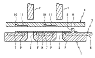
図1に、本発明の一実施形態に係るフレキシブルプリント配線板の製造設備を示す。当該製造設備は1枚のフレキシブルプリント配線板シートSから複数のフレキシブルプリント配線板個片Pを打ち抜き加工によって切り離すダイ1及びパンチ2と、切り離されたフレキシブルプリント配線板個片Pをダイ1からはね出すために用いられる板状治具3と、この板状治具3に位置決め可能なトレー4とを備える。[Flexible printed wiring board manufacturing equipment]
FIG. 1 shows a manufacturing facility for a flexible printed wiring board according to an embodiment of the present invention. The manufacturing equipment includes a die 1 and a
板状治具3は、それ自体が本発明の別の実施形態である。また、上記板状治具3とトレー4とは、本発明の別の実施形態に係るフレキシブルプリント配線板個片のハンドリング用具を構成する。なお、図では、板状治具3との対応を示すためにトレー4をダイ1の上に示しているが、トレー4は、板状治具3をダイ1から取り出した状態で、板状治具3に重ね合わされてもよい。
The
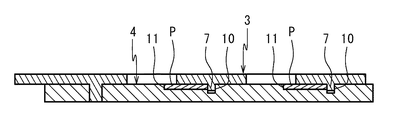
<フレキシブルプリント配線板シート>
フレキシブルプリント配線板シートSは、図2に示すように、複数のフレキシブルプリント配線板個片Pの導電パターン(不図示)が形成され、各フレキシブルプリント配線板個片Pの外縁を複数回に分けて打ち抜くことで、複数のフレキシブルプリント配線板個片Pを切り離すよう形成される。<Flexible printed wiring board sheet>
As shown in FIG. 2, in the flexible printed wiring board sheet S, a conductive pattern (not shown) of a plurality of flexible printed wiring board pieces P is formed, and the outer edge of each flexible printed wiring board piece P is divided into a plurality of times. It is formed so as to separate a plurality of flexible printed wiring board pieces P by punching.
当該フレキシブルプリント配線板の製造設備において複数のフレキシブルプリント配線板個片Pを切り離す直前のフレキシブルプリント配線板シートSは、複数のフレキシブルプリント配線板個片Pと、フレキシブルプリント配線板個片Pの数箇所から延出する小さい接続部Cと、この接続部Cを介して複数のフレキシブルプリント配線板個片Pと接続され、複数のフレキシブルプリント配線板個片Pを保持する枠部Fとを有する。換言すると、このフレキシブルプリント配線板シートSは、接続部Cの部分を除いて各フレキシブルプリント配線板個片Pの外縁を画定する複数の打抜穴Hが形成されている。 In the flexible printed wiring board manufacturing facility, the flexible printed wiring board sheet S immediately before separating the plurality of flexible printed wiring board pieces P is the number of the plurality of flexible printed wiring board pieces P and the number of the flexible printed wiring board pieces P. It has a small connecting portion C extending from a portion and a frame portion F connected to a plurality of flexible printed wiring board individual pieces P via the connecting portion C and holding a plurality of flexible printed wiring board individual pieces P. In other words, the flexible printed wiring board sheet S is formed with a plurality of punched holes H that define the outer edge of each flexible printed wiring board piece P except for the connection portion C.
<ダイ>
ダイ1は、それぞれパンチ2が挿通される複数のパンチ穴5と、板状治具3が嵌合する位置決め凹部6を有する。<Die>
Each die 1 has a plurality of
パンチ穴5は、フレキシブルプリント配線板シートSの接続部Cに重なるよう配設される。つまり、パンチ穴5は、フレキシブルプリント配線板シートSの接続部Cを打ち抜くことにより、各フレキシブルプリント配線板個片Pを切り離すことができるような形状及び配置で形成される。 The punch holes 5 are arranged so as to overlap the connection portion C of the flexible printed wiring board sheet S. That is, the punch holes 5 are formed in a shape and arrangement so that the individual flexible printed wiring board pieces P can be separated by punching the connection portion C of the flexible printed wiring board sheet S.
位置決め凹部6の板状治具3との嵌合形状、つまり平面視での外形形状は、特に限定されない。また、位置決め凹部6は、板状治具3の上に載置されるフレキシブルプリント配線板シートSにパンチ穴5のエッジを当接させるよう、パンチ穴5の近傍領域を残して形成される。
The fitting shape of the
<パンチ>
パンチ2は、パンチ穴5に嵌合する形状を有し、不図示の駆動機構によってパンチ穴5に抜挿される。<Punch>
The
<板状治具>
板状治具3は、ダイ1及びパンチ2を用いて1枚のフレキシブルプリント配線板シートSから切り離される複数のフレキシブルプリント配線板個片Pを、ダイ1からはね出すために用いられる。つまり、板状治具3を持ち上げることによって、複数のフレキシブルプリント配線板個片Pを同時にダイ1から取り上げることができる。<Plate jig>
The plate-shaped
板状治具3は、部分的にダイ1の位置決め凹部6に嵌合するが、ダイ1から取り上げることが容易となるよう、部分的には位置決め凹部6から突出するよう形成されることが好ましい。
The
板状治具3は、各フレキシブルプリント配線板個片Pの平面方向の移動を防止する複数のガイド7と、トレー4に対して位置決めする位置決め部8とを備える。
The plate-shaped
(ガイド)
ガイド7は、フレキシブルプリント配線板シートSを載置する面に突設される。このガイド7は、板状治具3上にフレキシブルプリント配線板シートSを載置したとき、フレキシブルプリント配線板シートSの打抜穴Hに挿入されてフレキシブルプリント配線板個片Pに隣接して配置される。(guide)
The
板状治具3は、各フレキシブルプリント配線板個片Pの周囲にそれぞれ複数のガイド7を配置するよう構成され、各フレキシブルプリント配線板個片Pをいずれの平面方向にも実質的に移動できないよう保持する。なお、複数のガイド7は、各フレキシブルプリント配線板個片Pとの間に、後工程で支障のない程度にフレキシブルプリント配線板個片Pの移動を許容する隙間を有してもよい。
The
ガイド7の平均高さの下限としては、フレキシブルプリント配線板シートSの平均厚さの7倍が好ましく、10倍がより好ましい。一方、ガイド7の平均高さの上限としては、フレキシブルプリント配線板シートSの平均厚さの50倍が好ましく、20倍がより好ましい。ガイド7の平均高さが上記下限に満たない場合、フレキシブルプリント配線板個片Pの保持が不確実となるおそれがある。逆に、ガイド7の平均高さが上記上限を超える場合、トレー4の形状が不必要に制約されるおそれがある。
The lower limit of the average height of the
ガイド7の平面寸法としては、特に限定されず、十分な強度が得られかつフレキシブルプリント配線板シートSと干渉しない(打抜穴Hに挿入できる)ものとすればよい。
The plane dimension of the
ガイド7は、板材の表面のガイド7以外の部分を例えば機械加工、エッチング等で他の部分を除去することにより形成してもよく、金属組成物等の部材を部分的に付設することによって形成してもよい。上記部材を部分的に付設する方法としては、例えば別途機械加工やエッチング加工した上記部材を上記板材の表面に配置する方法等を適用することができる。
The
(位置決め部)
位置決め部8は、トレー4との位置決めに使用できるものであればどのようなものであってもよいが、図示する実施形態では、フレキシブルプリント配線板シートSを載置する面に突設されたピンである。また、本実施形態の位置決め部8は、板状治具3に対してフレキシブルプリント配線板シートSを位置決めするピンを兼ねている。(Positioning part)
The
<トレー>
トレー4は、ダイ1から複数のフレキシブルプリント配線板個片Pを取り上げた板状治具3から複数のフレキシブルプリント配線板個片Pが互いの位置関係を変えることなく、表裏を逆にして移載される。<Tray>
The
このため、トレー4は、板状治具3の位置決め部8と嵌合する嵌合部9と、板状治具3の複数のガイド7が挿入される複数の収容凹部10と、複数のフレキシブルプリント配線板個片Pを位置決めする保持構造11とを有する。
Therefore, the
(嵌合部)
嵌合部9は、板状治具3の位置決め部8の構成に対応するものであればよいが、本実施形態では、板状治具3の位置決め部(ピン)8が嵌合する位置決め穴である。この嵌合部9と板状治具3の位置決め部8との嵌合により、板状治具3上で複数のガイド7により位置決めされる複数のフレキシブルプリント配線板個片Pをトレー4の保持構造11に正対するよう、板状治具3とトレー4とを位置決めすることができる。(Fitting portion)
The
(収容凹部)
収容凹部10は、板状治具3のガイド7を受け入れることによって、板状治具3とトレー4とでフレキシブルプリント配線板個片Pを挟み込むことができるようにする。これにより、複数のフレキシブルプリント配線板個片Pの配置を変えずに板状治具3からトレー4に移載することがより確実となる。(Accommodation recess)
By accepting the
(保持構造)
保持構造11は、フレキシブルプリント配線板個片Pの平面方向の移動を実質的に防止できるものであればよく、図示する実施形態では、フレキシブルプリント配線板個片Pが嵌合する凹部である。(Holding structure)
The holding
<利点>
以上のように、当該フレキシブルプリント配線板の製造設備、当該フレキシブルプリント配線板個片のハンドリング用具(板状治具3とトレー4とのセット)及び板状治具3は、板状治具3がフレキシブルプリント配線板シートSから切り離された複数のフレキシブルプリント配線板個片Pを相対位置を変えずに保持してダイ1から取り出し、そのままの位置関係で一括してトレー4に移し替えることができるので、フレキシブルプリント配線板個片Pのハンドリングが容易である。<Advantage>
As described above, the manufacturing equipment for the flexible printed wiring board, the handling tool for the flexible printed wiring board piece (a set of the
[フレキシブルプリント配線板の製造方法]
本発明の別の実施形態に係るフレキシブルプリント配線板の製造方法は、図1の製造設備を用いて行うことができる。[Manufacturing method of flexible printed wiring board]
The method for manufacturing a flexible printed wiring board according to another embodiment of the present invention can be performed using the manufacturing equipment shown in FIG.
具体的には、当該フレキシブルプリント配線板の製造方法は、はね出しのための板状治具3が配置されるダイ1とこのダイ1に対応するパンチ2とを用い、1枚のフレキシブルプリント配線板シートSから複数のフレキシブルプリント配線板個片Pを切り離す工程<切り離し工程>と、板状治具3を持ち上げることにより複数のフレキシブルプリント配線板個片Pをはね出す工程<はね出し工程>と、複数のフレキシブルプリント配線板個片Pを位置決めする保持構造11を有するトレー4に、はね出した複数のフレキシブルプリント配線板個片Pを移載する工程<移載工程>とを備える。
Specifically, the method for manufacturing the flexible printed wiring board uses a die 1 on which a plate-shaped
<切り離し工程>
切り離し工程では、図3に示すように、板状治具3の上にフレキシブルプリント配線板シートSを位置決め配置し、フレキシブルプリント配線板シートSを保持する板状治具3をダイ1の位置決め凹部6に嵌合させる。この状態で、パンチ2をダイ1のパンチ穴5に挿入することで、フレキシブルプリント配線板シートSの接続部Cを打ち抜いて除去することができ、複数のフレキシブルプリント配線板個片Pが切り離される。<Separation process>
In the disconnection step, as shown in FIG. 3, the flexible printed wiring board sheet S is positioned and arranged on the
このとき、板状治具3の上には、複数のフレキシブルプリント配線板個片Pと共に枠部Fも残されているが、図4に示すように、最初に枠部Fを取り除いて板状治具3上には複数のフレキシブルプリント配線板個片Pのみを残してもよく、次のはね出し工程後に枠部Fを取り除いてもよい。
At this time, the frame portion F is also left on the plate-shaped
<はね出し工程>
はね出し工程では、図5に示すように、複数のフレキシブルプリント配線板個片Pが載置されている板状治具3を持ち上げて、複数のフレキシブルプリント配線板個片Pを載せたまま板状治具3をダイ1から取り外す。このとき、各フレキシブルプリント配線板個片Pがガイド7によって保持されているので、フレキシブルプリント配線板個片Pの相対配置を変えることなく板状治具3を移動することが容易である。<Splashing process>
In the splashing step, as shown in FIG. 5, the plate-shaped
<移載工程>
移載工程は、板状治具3にトレー4を重ね合わせる工程(重ね合わせ工程)と、板状治具3及びトレー4を上下反転させる工程(反転工程)とを有する。<Transfer process>
The transfer step includes a step of stacking the
(重ね合わせ工程)
重ね合わせ工程では、図6に示すように、複数のフレキシブルプリント配線板個片Pを保持する板状治具3の上に、トレー4を重ね合わせる。このとき、板状治具3の位置決め部8をトレー4の嵌合部9に嵌合させることにより、板状治具3のガイド7が収容凹部10に収容され、板状治具3上のフレキシブルプリント配線板個片Pが保持構造11に挿入されるよう板状治具3とトレー4とを正対させる。(Overlapping process)
In the stacking step, as shown in FIG. 6, the
(反転工程)
反転工程では、図7に示すように、複数のフレキシブルプリント配線板個片Pを挟み込んでいる板状治具3及びトレー4を上下反転させる。このとき、板状治具3のガイド7及びトレー4の保持構造11は、複数のフレキシブルプリント配線板個片Pの相対位置が変化することをより確実に防止する。これにより、図8に示すように、板状治具3を取り外してトレー4の保持構造11にそれぞれフレキシブルプリント配線板個片Pを正確に配置した状態とすることができ、次工程において、例えば素子の実装等、フレキシブルプリント配線板個片Pに対する加工を適切に行うことができる。(Reversal process)
In the reversing step, as shown in FIG. 7, the plate-shaped
[その他の実施形態]
今回開示された実施の形態は全ての点で例示であって制限的なものではないと考えられるべきである。本発明の範囲は、上記実施形態の構成に限定されるものではなく、請求の範囲によって示され、請求の範囲と均等の意味及び範囲内での全ての変更が含まれることが意図される。[Other Embodiments]
It should be considered that the embodiments disclosed this time are exemplary in all respects and not restrictive. The scope of the present invention is not limited to the configuration of the above-described embodiment, but is indicated by the claims and is intended to include all modifications within the meaning and scope equivalent to the claims.
当該板状治具は、フレキシブルプリント配線板個片を保持するガイドのみによってフレキシブルプリント配線板シートを位置決めするものであってもよい。また、当該板状治具は、トレーに対する位置決め部とは別にフレキシブルプリント配線板を位置決めする構成を備えてもよい。 The plate-shaped jig may be used to position the flexible printed wiring board sheet only by a guide that holds the flexible printed wiring board pieces. Further, the plate-shaped jig may have a configuration for positioning the flexible printed wiring board separately from the positioning portion for the tray.
当該板状治具は、そのまま次工程でフレキシブルプリント配線板個片を保持する治具として使用してもよい。また、当該板状治具から位置決めのための構造やフレキシブルプリント配線板個片を保持する構造を有しない平板にフレキシブルプリント配線板個片を移載してもよい。 The plate-shaped jig may be used as it is as a jig for holding the flexible printed wiring board piece in the next process. Further, the flexible printed wiring board piece may be transferred from the plate jig to a flat plate having no structure for positioning or a structure for holding the flexible printed wiring board piece.
当該板状治具のガイドは、フレキシブルプリント配線板個片の形状に合わせて屈曲した側面を有するものであってもよい。 The guide of the plate-shaped jig may have a side surface bent according to the shape of the flexible printed wiring board piece.
当該板状治具の位置決め部は、トレーの凸部に嵌合する凹部であってもよい。また、当該板状治具の位置決め部は、当該板状治具とトレーとを位置決めするさらなる治具等の構成要素による位置決めに供されるよう構成されてもよい。 The positioning portion of the plate-shaped jig may be a concave portion that fits into the convex portion of the tray. Further, the positioning portion of the plate-shaped jig may be configured to be provided for positioning by a component such as a further jig for positioning the plate-shaped jig and the tray.
当該フレキシブルプリント配線板個片のハンドリング用具において、トレーの保持構造は、上述の実施形態に限定されず、例えば板状治具のガイドのようにフレキシブルプリント配線板個片の周囲に配置される突起等、任意の構成とすることができる。 In the handling tool for the flexible printed wiring board piece, the tray holding structure is not limited to the above-described embodiment, and the protrusions arranged around the flexible printed wiring board piece, for example, like a guide of a plate jig. Etc., any configuration can be used.
フレキシブルプリント配線板の製造方法、板状治具、フレキシブルプリント配線板個片のハンドリング用具及びフレキシブルプリント配線板の製造設備において、フレキシブルプリント配線板シートは、複数種類のフレキシブルプリント配線板個片が形成されているものであってもよい。 In the manufacturing method of the flexible printed wiring board, the plate jig, the handling tool of the flexible printed wiring board piece, and the manufacturing equipment of the flexible printed wiring board, the flexible printed wiring board sheet is formed of a plurality of types of flexible printed wiring board pieces. It may be the one that has been done.
1 ダイ
2 パンチ
3 板状治具
4 トレー
5 パンチ穴
6 位置決め凹部
7 ガイド
8 位置決め部
9 嵌合部
10 収容凹部
11 保持構造
C 接続部
F 枠部
H 打抜穴
P フレキシブルプリント配線板個片
S フレキシブルプリント配線板シート1
Claims (4)
上記板状治具を持ち上げることにより複数のフレキシブルプリント配線板個片をはね出すはね出し工程と、
上記複数のフレキシブルプリント配線板個片を位置決めする保持構造を有するトレーに、はね出した上記複数のフレキシブルプリント配線板個片を移載する移載工程と
を備えるフレキシブルプリント配線板の製造方法であって、
上記板状治具が、複数のフレキシブルプリント配線板個片の平面方向の移動を防止する複数のガイドと、この複数のガイドにより位置決めされる複数のフレキシブルプリント配線板個片を上記トレーの保持構造に正対するよう上記トレーに対して位置決めする位置決め部とを有し、
上記移載工程が、上記板状治具に上記トレーを重ね合わせる重ね合わせ工程と、上記板状治具及びトレーを上下反転させる反転工程とを有するフレキシブルプリント配線板の製造方法。Using a die on which a plate-shaped jig for ejection is arranged and a punch corresponding to this die, a separation process for separating a plurality of flexible printed wiring board pieces from one flexible printed wiring board sheet, and a separation process.
By lifting the above-mentioned plate-shaped jig, a plurality of flexible printed wiring board pieces are ejected.
A method for manufacturing a flexible printed wiring board, which comprises a transfer step of transferring the plurality of flexible printed wiring board pieces that have been ejected to a tray having a holding structure for positioning the plurality of flexible printed wiring board pieces. There,
The plate-shaped jig holds a plurality of guides for preventing the movement of the plurality of flexible printed wiring board pieces in the plane direction, and a plurality of flexible printed wiring board pieces positioned by the plurality of guides in the tray. It has a positioning part for positioning with respect to the tray so as to face the tray.
A method for manufacturing a flexible printed wiring board, wherein the transfer step includes a stacking step of stacking the tray on the plate jig and an inversion step of flipping the plate jig and the tray upside down.
上記複数のフレキシブルプリント配線板個片の平面方向の移動を防止する複数のガイドと、
上記複数のフレキシブルプリント配線板個片を保持するトレーに対して位置決めする位置決め部と
を備える板状治具。A plate-shaped jig used to eject a plurality of flexible printed wiring board pieces separated from one flexible printed wiring board sheet using a die and a punch from the die.
A plurality of guides for preventing the movement of the plurality of flexible printed wiring board pieces in the plane direction, and
A plate-shaped jig provided with a positioning portion for positioning with respect to a tray that holds the plurality of flexible printed wiring board pieces.
上記トレーが、
上記位置決め部と嵌合する嵌合部と、
上記複数のガイドが挿入される複数の凹部と、
上記複数のフレキシブルプリント配線板個片を位置決めする保持構造と
を有するフレキシブルプリント配線板個片のハンドリング用具。A tool for handling individual pieces of a flexible printed wiring board including the plate-shaped jig according to claim 2 and a tray that can be positioned on the plate-shaped jig.
The above tray
A fitting part that fits with the positioning part and
Multiple recesses into which the above multiple guides are inserted, and
A tool for handling flexible printed wiring board pieces having a holding structure for positioning the plurality of flexible printed wiring board pieces.
上記板状治具が嵌合する凹部を有するダイと、
このダイに対応するパンチと
を備えるフレキシブルプリント配線板の製造設備。The handling tool for the flexible printed wiring board piece according to claim 3,
A die with a recess into which the plate jig fits, and
Flexible printed wiring board manufacturing equipment with punches for this die.
Applications Claiming Priority (3)
| Application Number | Priority Date | Filing Date | Title |
|---|---|---|---|
| JP2016224140 | 2016-11-17 | ||
| JP2016224140 | 2016-11-17 | ||
| PCT/JP2017/035977 WO2018092447A1 (en) | 2016-11-17 | 2017-10-03 | Flexible printed wiring board production method, plate-shaped jig, tool for handling individual flexible printed wiring board pieces, and flexible printed wiring board production equipment |
Publications (2)
| Publication Number | Publication Date |
|---|---|
| JPWO2018092447A1 JPWO2018092447A1 (en) | 2019-10-17 |
| JP6897937B2 true JP6897937B2 (en) | 2021-07-07 |
Family
ID=62146148
Family Applications (1)
| Application Number | Title | Priority Date | Filing Date |
|---|---|---|---|
| JP2018551064A Active JP6897937B2 (en) | 2016-11-17 | 2017-10-03 | Flexible printed wiring board manufacturing method, plate jigs, flexible printed wiring board piece handling tools, and flexible printed wiring board manufacturing equipment |
Country Status (3)
| Country | Link |
|---|---|
| JP (1) | JP6897937B2 (en) |
| CN (1) | CN109964545B (en) |
| WO (1) | WO2018092447A1 (en) |
Family Cites Families (18)
| Publication number | Priority date | Publication date | Assignee | Title |
|---|---|---|---|---|
| JPS4881063A (en) * | 1972-01-31 | 1973-10-30 | ||
| JPH05277872A (en) * | 1992-03-30 | 1993-10-26 | Toshiba Corp | Punching and conveying device for flexible circuit board |
| JP2662477B2 (en) * | 1992-06-03 | 1997-10-15 | 住友電気工業株式会社 | Flexible printed wiring board and method of manufacturing the same |
| CN1249672C (en) * | 1999-08-06 | 2006-04-05 | 阿尔卑斯电气株式会社 | Tray for conveying magnetic head for magnetic disk |
| JP3783528B2 (en) * | 2000-05-30 | 2006-06-07 | 松下電工株式会社 | Cutting method of molded circuit board |
| JP2003053696A (en) * | 2001-08-15 | 2003-02-26 | Uht Corp | Punching device for flexible workpiece |
| JP2004034161A (en) * | 2002-06-28 | 2004-02-05 | Uht Corp | Method for cutting flexible printed wiring board |
| JP3794693B2 (en) * | 2003-02-07 | 2006-07-05 | 松下電器産業株式会社 | Substrate holder, substrate holder manufacturing method, and mold manufacturing method |
| JP3654892B2 (en) * | 2003-05-30 | 2005-06-02 | 松下電器産業株式会社 | Holding tool and manufacturing method of holding tool |
| KR100615074B1 (en) * | 2004-10-18 | 2006-08-22 | 주식회사 써키트 플렉스 | Punching method of FPC with unconnected compound hard toolings |
| CN100420553C (en) * | 2005-11-02 | 2008-09-24 | 富展电子(上海)有限公司 | Method for die cutting flexible circuit board |
| JP2008053277A (en) * | 2006-08-22 | 2008-03-06 | Nec Corp | Apparatus and method of cutting off board |
| JP2008159968A (en) * | 2006-12-26 | 2008-07-10 | Fuji Electric Fa Components & Systems Co Ltd | Multiple printed board |
| CN101686604B (en) * | 2008-09-24 | 2011-05-18 | 比亚迪股份有限公司 | Flexible printed circuit whole board punching method |
| JP5581260B2 (en) * | 2011-04-21 | 2014-08-27 | 日本メクトロン株式会社 | Method for replacing unit wiring board of collective substrate and collective substrate |
| CN104227781B (en) * | 2014-09-23 | 2016-04-20 | 东莞市华恒工业自动化集成有限公司 | A kind of automatic punching machine equipment and processing method thereof |
| CN104828599B (en) * | 2015-04-28 | 2017-06-20 | 歌尔股份有限公司 | A kind of point board device automatically |
| JP3213228U (en) * | 2017-08-14 | 2017-10-26 | 住友電工プリントサーキット株式会社 | Transfer jig and jig set |
-
2017
- 2017-10-03 WO PCT/JP2017/035977 patent/WO2018092447A1/en active Application Filing
- 2017-10-03 JP JP2018551064A patent/JP6897937B2/en active Active
- 2017-10-03 CN CN201780071501.0A patent/CN109964545B/en active Active
Also Published As
| Publication number | Publication date |
|---|---|
| CN109964545B (en) | 2021-08-10 |
| WO2018092447A1 (en) | 2018-05-24 |
| CN109964545A (en) | 2019-07-02 |
| JPWO2018092447A1 (en) | 2019-10-17 |
Similar Documents
| Publication | Publication Date | Title |
|---|---|---|
| EP1842634B1 (en) | Method of manufacturing industrial component having through holes with high aspect ratio | |
| JP6571176B2 (en) | Component mounter and component supply method for component mounter | |
| JP6897937B2 (en) | Flexible printed wiring board manufacturing method, plate jigs, flexible printed wiring board piece handling tools, and flexible printed wiring board manufacturing equipment | |
| JP6901066B2 (en) | Flexible printed wiring board manufacturing method and flexible printed wiring board manufacturing equipment | |
| JP4472582B2 (en) | Mounting method for flexible circuit board | |
| KR101841162B1 (en) | Apparatus for press forming of flexible printed circuit board | |
| JP6718693B2 (en) | Equipment with backup jig | |
| JP2003025284A (en) | High speed cnc punching device | |
| JP2007281440A (en) | Sheet holding fixture and method of holding sheet-form base material | |
| JP6738898B2 (en) | Board-to-board working machine | |
| JP7108807B2 (en) | Screen printing system and screen printing method | |
| JP7075498B2 (en) | Working machine | |
| JP2010003933A (en) | Flexible printed circuit board and method of holding the same in electronic apparatus | |
| JP5903668B2 (en) | Component mounting apparatus and component mounting method | |
| WO2018131139A1 (en) | Component mounting device | |
| JPH0919914A (en) | Green sheet laminating device | |
| JP4808727B2 (en) | Drilling device | |
| TWI798960B (en) | Method for fixing printed circuit board of groove processing device and groove processing device | |
| WO2018189862A1 (en) | Work machine | |
| JP2005072299A (en) | Packaging equipment of electronic component, its arrangement holder, and vacuum chuck | |
| JPH0318098A (en) | Method of holding sheet member | |
| JPH10261867A (en) | Manufacturing method and device of multilayer ceramic board | |
| JP2002036224A (en) | Manufacturing method of laminated ceramic electronic component | |
| JP5427830B2 (en) | Drilling device, punching die and exchanging method of punching die | |
| JP2022063968A (en) | Work machine |
Legal Events
| Date | Code | Title | Description |
|---|---|---|---|
| A625 | Written request for application examination (by other person) |
Free format text: JAPANESE INTERMEDIATE CODE: A625 Effective date: 20200521 |
|
| TRDD | Decision of grant or rejection written | ||
| A01 | Written decision to grant a patent or to grant a registration (utility model) |
Free format text: JAPANESE INTERMEDIATE CODE: A01 Effective date: 20210511 |
|
| A61 | First payment of annual fees (during grant procedure) |
Free format text: JAPANESE INTERMEDIATE CODE: A61 Effective date: 20210602 |
|
| R150 | Certificate of patent or registration of utility model |
Ref document number: 6897937 Country of ref document: JP Free format text: JAPANESE INTERMEDIATE CODE: R150 |
|
| R250 | Receipt of annual fees |
Free format text: JAPANESE INTERMEDIATE CODE: R250 |