JP6896889B2 - 溶接構造、および金属片付き配線基板 - Google Patents
溶接構造、および金属片付き配線基板 Download PDFInfo
- Publication number
- JP6896889B2 JP6896889B2 JP2019562141A JP2019562141A JP6896889B2 JP 6896889 B2 JP6896889 B2 JP 6896889B2 JP 2019562141 A JP2019562141 A JP 2019562141A JP 2019562141 A JP2019562141 A JP 2019562141A JP 6896889 B2 JP6896889 B2 JP 6896889B2
- Authority
- JP
- Japan
- Prior art keywords
- metal member
- hole
- metal
- nugget
- wiring pattern
- Prior art date
- Legal status (The legal status is an assumption and is not a legal conclusion. Google has not performed a legal analysis and makes no representation as to the accuracy of the status listed.)
- Active
Links
Images
Classifications
-
- B—PERFORMING OPERATIONS; TRANSPORTING
- B23—MACHINE TOOLS; METAL-WORKING NOT OTHERWISE PROVIDED FOR
- B23K—SOLDERING OR UNSOLDERING; WELDING; CLADDING OR PLATING BY SOLDERING OR WELDING; CUTTING BY APPLYING HEAT LOCALLY, e.g. FLAME CUTTING; WORKING BY LASER BEAM
- B23K26/00—Working by laser beam, e.g. welding, cutting or boring
- B23K26/20—Bonding
- B23K26/21—Bonding by welding
- B23K26/24—Seam welding
- B23K26/244—Overlap seam welding
-
- B—PERFORMING OPERATIONS; TRANSPORTING
- B23—MACHINE TOOLS; METAL-WORKING NOT OTHERWISE PROVIDED FOR
- B23K—SOLDERING OR UNSOLDERING; WELDING; CLADDING OR PLATING BY SOLDERING OR WELDING; CUTTING BY APPLYING HEAT LOCALLY, e.g. FLAME CUTTING; WORKING BY LASER BEAM
- B23K26/00—Working by laser beam, e.g. welding, cutting or boring
- B23K26/20—Bonding
- B23K26/21—Bonding by welding
- B23K26/24—Seam welding
- B23K26/28—Seam welding of curved planar seams
-
- B—PERFORMING OPERATIONS; TRANSPORTING
- B23—MACHINE TOOLS; METAL-WORKING NOT OTHERWISE PROVIDED FOR
- B23K—SOLDERING OR UNSOLDERING; WELDING; CLADDING OR PLATING BY SOLDERING OR WELDING; CUTTING BY APPLYING HEAT LOCALLY, e.g. FLAME CUTTING; WORKING BY LASER BEAM
- B23K26/00—Working by laser beam, e.g. welding, cutting or boring
- B23K26/20—Bonding
- B23K26/32—Bonding taking account of the properties of the material involved
- B23K26/323—Bonding taking account of the properties of the material involved involving parts made of dissimilar metallic material
-
- H—ELECTRICITY
- H01—ELECTRIC ELEMENTS
- H01R—ELECTRICALLY-CONDUCTIVE CONNECTIONS; STRUCTURAL ASSOCIATIONS OF A PLURALITY OF MUTUALLY-INSULATED ELECTRICAL CONNECTING ELEMENTS; COUPLING DEVICES; CURRENT COLLECTORS
- H01R12/00—Structural associations of a plurality of mutually-insulated electrical connecting elements, specially adapted for printed circuits, e.g. printed circuit boards [PCB], flat or ribbon cables, or like generally planar structures, e.g. terminal strips, terminal blocks; Coupling devices specially adapted for printed circuits, flat or ribbon cables, or like generally planar structures; Terminals specially adapted for contact with, or insertion into, printed circuits, flat or ribbon cables, or like generally planar structures
- H01R12/50—Fixed connections
- H01R12/59—Fixed connections for flexible printed circuits, flat or ribbon cables or like structures
-
- H—ELECTRICITY
- H01—ELECTRIC ELEMENTS
- H01R—ELECTRICALLY-CONDUCTIVE CONNECTIONS; STRUCTURAL ASSOCIATIONS OF A PLURALITY OF MUTUALLY-INSULATED ELECTRICAL CONNECTING ELEMENTS; COUPLING DEVICES; CURRENT COLLECTORS
- H01R4/00—Electrically-conductive connections between two or more conductive members in direct contact, i.e. touching one another; Means for effecting or maintaining such contact; Electrically-conductive connections having two or more spaced connecting locations for conductors and using contact members penetrating insulation
- H01R4/02—Soldered or welded connections
- H01R4/029—Welded connections
-
- H—ELECTRICITY
- H01—ELECTRIC ELEMENTS
- H01R—ELECTRICALLY-CONDUCTIVE CONNECTIONS; STRUCTURAL ASSOCIATIONS OF A PLURALITY OF MUTUALLY-INSULATED ELECTRICAL CONNECTING ELEMENTS; COUPLING DEVICES; CURRENT COLLECTORS
- H01R43/00—Apparatus or processes specially adapted for manufacturing, assembling, maintaining, or repairing of line connectors or current collectors or for joining electric conductors
- H01R43/02—Apparatus or processes specially adapted for manufacturing, assembling, maintaining, or repairing of line connectors or current collectors or for joining electric conductors for soldered or welded connections
- H01R43/0221—Laser welding
-
- H—ELECTRICITY
- H05—ELECTRIC TECHNIQUES NOT OTHERWISE PROVIDED FOR
- H05K—PRINTED CIRCUITS; CASINGS OR CONSTRUCTIONAL DETAILS OF ELECTRIC APPARATUS; MANUFACTURE OF ASSEMBLAGES OF ELECTRICAL COMPONENTS
- H05K1/00—Printed circuits
- H05K1/02—Details
- H05K1/11—Printed elements for providing electric connections to or between printed circuits
- H05K1/118—Printed elements for providing electric connections to or between printed circuits specially for flexible printed circuits, e.g. using folded portions
-
- H—ELECTRICITY
- H05—ELECTRIC TECHNIQUES NOT OTHERWISE PROVIDED FOR
- H05K—PRINTED CIRCUITS; CASINGS OR CONSTRUCTIONAL DETAILS OF ELECTRIC APPARATUS; MANUFACTURE OF ASSEMBLAGES OF ELECTRICAL COMPONENTS
- H05K3/00—Apparatus or processes for manufacturing printed circuits
- H05K3/30—Assembling printed circuits with electric components, e.g. with resistor
- H05K3/32—Assembling printed circuits with electric components, e.g. with resistor electrically connecting electric components or wires to printed circuits
- H05K3/328—Assembling printed circuits with electric components, e.g. with resistor electrically connecting electric components or wires to printed circuits by welding
-
- B—PERFORMING OPERATIONS; TRANSPORTING
- B23—MACHINE TOOLS; METAL-WORKING NOT OTHERWISE PROVIDED FOR
- B23K—SOLDERING OR UNSOLDERING; WELDING; CLADDING OR PLATING BY SOLDERING OR WELDING; CUTTING BY APPLYING HEAT LOCALLY, e.g. FLAME CUTTING; WORKING BY LASER BEAM
- B23K2101/00—Articles made by soldering, welding or cutting
- B23K2101/36—Electric or electronic devices
- B23K2101/42—Printed circuits
-
- B—PERFORMING OPERATIONS; TRANSPORTING
- B23—MACHINE TOOLS; METAL-WORKING NOT OTHERWISE PROVIDED FOR
- B23K—SOLDERING OR UNSOLDERING; WELDING; CLADDING OR PLATING BY SOLDERING OR WELDING; CUTTING BY APPLYING HEAT LOCALLY, e.g. FLAME CUTTING; WORKING BY LASER BEAM
- B23K2103/00—Materials to be soldered, welded or cut
- B23K2103/08—Non-ferrous metals or alloys
- B23K2103/10—Aluminium or alloys thereof
-
- B—PERFORMING OPERATIONS; TRANSPORTING
- B23—MACHINE TOOLS; METAL-WORKING NOT OTHERWISE PROVIDED FOR
- B23K—SOLDERING OR UNSOLDERING; WELDING; CLADDING OR PLATING BY SOLDERING OR WELDING; CUTTING BY APPLYING HEAT LOCALLY, e.g. FLAME CUTTING; WORKING BY LASER BEAM
- B23K2103/00—Materials to be soldered, welded or cut
- B23K2103/08—Non-ferrous metals or alloys
- B23K2103/12—Copper or alloys thereof
-
- B—PERFORMING OPERATIONS; TRANSPORTING
- B23—MACHINE TOOLS; METAL-WORKING NOT OTHERWISE PROVIDED FOR
- B23K—SOLDERING OR UNSOLDERING; WELDING; CLADDING OR PLATING BY SOLDERING OR WELDING; CUTTING BY APPLYING HEAT LOCALLY, e.g. FLAME CUTTING; WORKING BY LASER BEAM
- B23K2103/00—Materials to be soldered, welded or cut
- B23K2103/18—Dissimilar materials
- B23K2103/20—Ferrous alloys and aluminium or alloys thereof
-
- B—PERFORMING OPERATIONS; TRANSPORTING
- B23—MACHINE TOOLS; METAL-WORKING NOT OTHERWISE PROVIDED FOR
- B23K—SOLDERING OR UNSOLDERING; WELDING; CLADDING OR PLATING BY SOLDERING OR WELDING; CUTTING BY APPLYING HEAT LOCALLY, e.g. FLAME CUTTING; WORKING BY LASER BEAM
- B23K2103/00—Materials to be soldered, welded or cut
- B23K2103/18—Dissimilar materials
- B23K2103/22—Ferrous alloys and copper or alloys thereof
-
- H—ELECTRICITY
- H01—ELECTRIC ELEMENTS
- H01R—ELECTRICALLY-CONDUCTIVE CONNECTIONS; STRUCTURAL ASSOCIATIONS OF A PLURALITY OF MUTUALLY-INSULATED ELECTRICAL CONNECTING ELEMENTS; COUPLING DEVICES; CURRENT COLLECTORS
- H01R12/00—Structural associations of a plurality of mutually-insulated electrical connecting elements, specially adapted for printed circuits, e.g. printed circuit boards [PCB], flat or ribbon cables, or like generally planar structures, e.g. terminal strips, terminal blocks; Coupling devices specially adapted for printed circuits, flat or ribbon cables, or like generally planar structures; Terminals specially adapted for contact with, or insertion into, printed circuits, flat or ribbon cables, or like generally planar structures
- H01R12/50—Fixed connections
- H01R12/59—Fixed connections for flexible printed circuits, flat or ribbon cables or like structures
- H01R12/62—Fixed connections for flexible printed circuits, flat or ribbon cables or like structures connecting to rigid printed circuits or like structures
-
- H—ELECTRICITY
- H05—ELECTRIC TECHNIQUES NOT OTHERWISE PROVIDED FOR
- H05K—PRINTED CIRCUITS; CASINGS OR CONSTRUCTIONAL DETAILS OF ELECTRIC APPARATUS; MANUFACTURE OF ASSEMBLAGES OF ELECTRICAL COMPONENTS
- H05K2201/00—Indexing scheme relating to printed circuits covered by H05K1/00
- H05K2201/09—Shape and layout
- H05K2201/09209—Shape and layout details of conductors
- H05K2201/09654—Shape and layout details of conductors covering at least two types of conductors provided for in H05K2201/09218 - H05K2201/095
- H05K2201/0969—Apertured conductors
Landscapes
- Engineering & Computer Science (AREA)
- Physics & Mathematics (AREA)
- Optics & Photonics (AREA)
- Plasma & Fusion (AREA)
- Mechanical Engineering (AREA)
- Manufacturing & Machinery (AREA)
- Microelectronics & Electronic Packaging (AREA)
- Laser Beam Processing (AREA)
- Connections Effected By Soldering, Adhesion, Or Permanent Deformation (AREA)
- Coupling Device And Connection With Printed Circuit (AREA)
Description
本願は、2017年12月28日に、日本に出願された特願2017−253541号に基づき優先権を主張し、その内容をここに援用する。
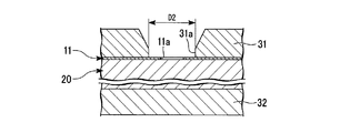
本実施形態では、図1Aに示すような薄膜状の第1金属部材11を、第2金属部材20に溶接するための溶接方法などについて説明する。第1金属部材11は、第2金属部材20の表面(上面)に重ねられている。以下では、第1金属部材11と第2金属部材20とが重ねられた方向を上下方向という。また、上下方向に沿って、第1金属部材11側を上方といい、第2金属部材20側を下方という。
また、第1金属部材11における後述の穴11aの中心を通り、上下方向に沿う直線を、中心軸線Cという(図2、図3参照)。上下方向から見た平面視において、中心軸線Cに交差する方向を径方向という。
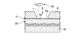
図1A〜図1Dは、本実施形態に係る溶接方法の説明図であり、上下方向に沿う断面を示している。第1金属部材11と第2金属部材20とを溶接する場合、まず図1Aに示すように、第2金属部材20の上面に第1金属部材11を重ねる(準備工程)。このとき、第1金属部材11には、予め穴11aを形成しておく。穴11aの形状は、円形または略円形であることが好ましい。本実施形態では、穴11aの内径(直径)を、穴直径D1と表す。穴直径D1は、例えば0.5mm程度である。
0<R2<D1÷2<R1<D2÷2 …(1)
次に、上記溶接方法によって得られる溶接構造1について、図3を用いて説明する。図3は、図1Dにおけるナゲット部22周辺の拡大図である。図3に示すように、ナゲット部22と非溶融部21との界面には、上方に向けて凸の突状界面21aが含まれている。突状界面21aは、ナゲット部22の径方向における中央部に位置している。これは、先述の通り、レーザー光Lの軌跡Tが上面視で略環状であることによる。より詳しくは、図2における中心軸線Cの近傍にはレーザー光Lが照射されないため、第2金属部材20のうち中心軸線Cに近い部分ほど熱が与えられず溶融しない。また、レーザー光Lは上方から照射されるため、第2金属部材20のうち下方に位置する部分ほど熱が伝わらず溶融しない。従って、図3に示すような突状界面21aが形成される。
このように、オーバーラップ部11bが形成されることで、第1金属部材11と第2金属部材20とが溶接される界面の面積が大きくなり、溶接強度をより高めることができる。
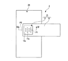
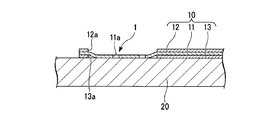
本実施形態の溶接構造1は、例えば図4A、図4Bに示すような金属片付き配線基板2に適用することができる。金属片付き配線基板2は、フレキシブルプリント基板(FPC:Flexible Printed circuit)10と、金属片(第2金属部材)20とを備えている。
上記条件では、穴ありのサンプルにおける溶接後穴直径D1’(図3参照)が0.85〜0.9mmとなった。
表1に示す「抵抗値」は、各サンプルについて、図4Aに示す点P1と点P2との間の電気抵抗を測定した結果である。点P1と点P2との間の間隔は10mmとした。
表1に示すように、穴なしのサンプルでは抵抗値の平均が0.35mΩであり、穴ありのサンプルでは抵抗値の平均が0.23mΩとなった。このように、穴11aを予め形成することで、電気抵抗を約34%低減することができた。
表1に示す「接合強度」は、各サンプルについて、図5に示すような引張り試験機を用いて接合強度を測定した結果である。より詳しくは、フレキシブルプリント基板10を第1クランプK1で挟持し、金属片20を第2クランプK2で挟持する。そして、第1クランプK1と第2クランプK2とを10mm/分の速度で離間させたときの、引っ張り力の最大値を、接合強度として記録した。
また、図3に示すように上下方向に沿う断面視において、第2金属部材20におけるナゲット部22と非溶融部21との境界に、上方に向けて凸の突状界面21aが含まれている。これにより、非溶融部21とナゲット部22との間で剥離が生じることが抑えられ、接合強度をより確実に高めることができる。
また、レーザー光Lの軌跡Tが、上面視で渦巻き状であることで、溶接のパラメータであるP、R1、R2、D1などを調整することで、共晶部Aの厚さを容易に制御することができる。
また、レーザー光Lの軌跡Tを、穴11aの径方向内側(第2点X2)から径方向外側(第1点X1)へと向かわせてもよい。
また、軌跡Tは、例えば中心軸線Cを中心とした放射状にすることで、全体として略環状となっていてもよい。
Claims (3)
- 互いに重ねられ、かつ溶接された第1金属部材および第2金属部材を備え、
前記第1金属部材は穴を有し、
前記第2金属部材は、レーザー光の熱によって溶融した前記第2金属部材の一部が、再び凝固した部分であるナゲット部を有し、
前記第1金属部材における前記穴の周縁部が前記ナゲット部を覆っており、
前記穴を通して前記ナゲット部の一部が露出している、溶接構造。 - 前記第1金属部材と前記第2金属部材が重ねられた上下方向に沿う断面視において、前記第2金属部材における前記ナゲット部と非溶融部との境界に、前記上下方向における第1金属部材側に向けて凸の突状界面が含まれている、請求項1に記載の溶接構造。
- 配線パターンと、該配線パターンを挟む基材およびカバーレイと、を有するフレキシブルプリント基板と、
前記配線パターンに溶接された金属片と、を備え、
前記配線パターンは穴を有し、
前記金属片は、レーザー光の熱によって溶融した前記金属片の一部が、再び凝固した部分であるナゲット部を有し、
前記配線パターンにおける前記穴の周縁部が前記ナゲット部を覆っており、
前記穴を通して前記ナゲット部の一部が露出している、金属片付き配線基板。
Applications Claiming Priority (3)
| Application Number | Priority Date | Filing Date | Title |
|---|---|---|---|
| JP2017253541 | 2017-12-28 | ||
| JP2017253541 | 2017-12-28 | ||
| PCT/JP2018/048031 WO2019131828A1 (ja) | 2017-12-28 | 2018-12-27 | 溶接構造、金属片付き配線基板、および溶接方法 |
Publications (2)
| Publication Number | Publication Date |
|---|---|
| JPWO2019131828A1 JPWO2019131828A1 (ja) | 2020-11-19 |
| JP6896889B2 true JP6896889B2 (ja) | 2021-06-30 |
Family
ID=67063789
Family Applications (1)
| Application Number | Title | Priority Date | Filing Date |
|---|---|---|---|
| JP2019562141A Active JP6896889B2 (ja) | 2017-12-28 | 2018-12-27 | 溶接構造、および金属片付き配線基板 |
Country Status (5)
| Country | Link |
|---|---|
| US (1) | US11597038B2 (ja) |
| EP (1) | EP3733339B1 (ja) |
| JP (1) | JP6896889B2 (ja) |
| CN (2) | CN113618237B (ja) |
| WO (1) | WO2019131828A1 (ja) |
Families Citing this family (5)
| Publication number | Priority date | Publication date | Assignee | Title |
|---|---|---|---|---|
| WO2021111966A1 (ja) * | 2019-12-05 | 2021-06-10 | 株式会社フジクラ | 金属片付き配線基板 |
| CN114346601B (zh) * | 2021-12-28 | 2023-01-31 | 富联裕展科技(深圳)有限公司 | 复合材料结构以及复合材料结构的加工方法 |
| WO2023234689A1 (ko) * | 2022-05-31 | 2023-12-07 | 주식회사 엘지에너지솔루션 | 레이저 용접장치 및 이를 이용한 용접방법 |
| WO2024063255A1 (ko) * | 2022-09-23 | 2024-03-28 | 삼성전자주식회사 | 하우징과 연결된 안테나 구조를 포함하는 전자 장치 |
| CN118616910B (zh) * | 2024-08-09 | 2024-10-25 | 北京金橙子科技股份有限公司 | 一种对环形图案的交叉填充方法及存储介质 |
Family Cites Families (21)
| Publication number | Priority date | Publication date | Assignee | Title |
|---|---|---|---|---|
| JPS6057430B2 (ja) * | 1980-11-29 | 1985-12-14 | 松下電工株式会社 | レ−ザビ−ムによる溶接方法 |
| US5306891A (en) * | 1992-04-02 | 1994-04-26 | Motorola, Inc. | Laser welding process for attaching metal to ceramic substrate |
| JPH08332582A (ja) * | 1995-06-05 | 1996-12-17 | Toshiba Corp | レーザ溶接方法 |
| JPH10334956A (ja) | 1997-05-28 | 1998-12-18 | Harness Sogo Gijutsu Kenkyusho:Kk | レーザ溶接構造 |
| JP3343066B2 (ja) * | 1997-11-04 | 2002-11-11 | 株式会社オートネットワーク技術研究所 | バスバーのレーザ溶接構造 |
| JP2005123419A (ja) * | 2003-10-17 | 2005-05-12 | Tohoku Pioneer Corp | 配線基板、配線パターンの形成方法、有機elパネル |
| JP2005347143A (ja) * | 2004-06-04 | 2005-12-15 | Fujikura Ltd | コネクタ |
| JP2007265962A (ja) * | 2006-02-28 | 2007-10-11 | Hitachi Ltd | レーザ溶接方法,コントロールユニットの製造方法、及び車両用コントロールユニット |
| JP5118862B2 (ja) * | 2007-03-05 | 2013-01-16 | トヨタ自動車株式会社 | レーザ接合方法 |
| JP5248344B2 (ja) * | 2009-01-20 | 2013-07-31 | 本田技研工業株式会社 | レーザ溶接方法 |
| WO2012164839A1 (ja) * | 2011-05-30 | 2012-12-06 | パナソニック株式会社 | レーザ接合部品およびその製造方法 |
| JP5932323B2 (ja) * | 2011-12-19 | 2016-06-08 | 株式会社東芝 | 二次電池及び二次電池の製造方法 |
| CN102896398A (zh) * | 2012-10-10 | 2013-01-30 | 上海交通大学 | 基于cmt的铝合金电弧点焊方法及焊接系统 |
| WO2014123022A1 (ja) | 2013-02-05 | 2014-08-14 | 株式会社日立製作所 | レーザ接合装置及びレーザ接合方法 |
| CN105358282B (zh) * | 2013-07-31 | 2017-10-13 | 新日铁住金株式会社 | 电弧点焊接头及其制造方法 |
| US10155285B2 (en) * | 2014-01-10 | 2018-12-18 | Panasonic Intellectual Property Management Co., Ltd. | Laser welding method and laser welding device |
| CN106029291B (zh) | 2014-02-25 | 2018-05-04 | 松下知识产权经营株式会社 | 激光焊接方法 |
| CN105855706B (zh) * | 2015-02-09 | 2018-02-13 | 司浦爱激光技术英国有限公司 | 激光焊缝 |
| GB201502149D0 (en) * | 2015-02-09 | 2015-03-25 | Spi Lasers Uk Ltd | Apparatus and method for laser welding |
| JP6149887B2 (ja) * | 2015-04-03 | 2017-06-21 | トヨタ自動車株式会社 | 溶接方法 |
| US10118249B2 (en) * | 2015-10-15 | 2018-11-06 | GM Global Technology Operations LLC | Laser beam welding with a spiral weld path having a first order of continuity |
-
2018
- 2018-12-27 EP EP18895465.5A patent/EP3733339B1/en active Active
- 2018-12-27 US US16/650,726 patent/US11597038B2/en active Active
- 2018-12-27 JP JP2019562141A patent/JP6896889B2/ja active Active
- 2018-12-27 CN CN202110880212.3A patent/CN113618237B/zh active Active
- 2018-12-27 WO PCT/JP2018/048031 patent/WO2019131828A1/ja not_active Ceased
- 2018-12-27 CN CN201880061937.6A patent/CN111163896B/zh active Active
Also Published As
| Publication number | Publication date |
|---|---|
| US20200306882A1 (en) | 2020-10-01 |
| CN111163896A (zh) | 2020-05-15 |
| JPWO2019131828A1 (ja) | 2020-11-19 |
| WO2019131828A1 (ja) | 2019-07-04 |
| EP3733339A1 (en) | 2020-11-04 |
| CN113618237A (zh) | 2021-11-09 |
| CN111163896B (zh) | 2022-10-04 |
| CN113618237B (zh) | 2023-09-22 |
| EP3733339A4 (en) | 2021-11-17 |
| US11597038B2 (en) | 2023-03-07 |
| EP3733339B1 (en) | 2024-02-07 |
Similar Documents
| Publication | Publication Date | Title |
|---|---|---|
| JP6896889B2 (ja) | 溶接構造、および金属片付き配線基板 | |
| CN108941912B (zh) | 印刷电路基板的接合构造及印刷电路基板的焊接方法 | |
| JP2011173146A (ja) | レーザ溶接方法 | |
| JPWO2017047050A1 (ja) | 金属部材の溶接構造および溶接方法 | |
| CN108883484A (zh) | 接合结构 | |
| JPWO2017170518A1 (ja) | 接合構造 | |
| JP6130295B2 (ja) | 摩擦撹拌接合継手を有する電気化学的陽極およびこのような陽極の製造方法 | |
| WO2015159514A1 (ja) | レーザ溶接方法 | |
| JP2011005499A (ja) | アルミニウム部材と銅部材との突き合わせレーザ溶接方法 | |
| WO2012164839A1 (ja) | レーザ接合部品およびその製造方法 | |
| JP7110907B2 (ja) | 異種金属部材の重ね溶接方法 | |
| US10421153B2 (en) | Laser welding method and laser welding device | |
| JP7181171B2 (ja) | 導線の接合方法 | |
| JP6735898B2 (ja) | レーザ溶接方法 | |
| JP7535721B2 (ja) | レーザ加工方法およびレーザ加工装置 | |
| CN113710401B (zh) | 接合结构 | |
| JP2020097039A (ja) | 異種金属部材の重ね溶接方法 | |
| CN111819026B (zh) | 接合结构以及接合方法 | |
| CN113692328A (zh) | 接合结构 | |
| WO2018088367A1 (ja) | 接合構造体及びその製造方法 | |
| JP2023089462A (ja) | 異種金属の接合方法、接合体、および接合装置 | |
| JP6591952B2 (ja) | 接合構造体及びその製造方法 | |
| JPS60210383A (ja) | 細線接合方法 | |
| JP2012016741A (ja) | レーザ隅肉溶接方法 | |
| WO2021111966A1 (ja) | 金属片付き配線基板 |
Legal Events
| Date | Code | Title | Description |
|---|---|---|---|
| A521 | Request for written amendment filed |
Free format text: JAPANESE INTERMEDIATE CODE: A523 Effective date: 20200319 |
|
| A621 | Written request for application examination |
Free format text: JAPANESE INTERMEDIATE CODE: A621 Effective date: 20200319 |
|
| TRDD | Decision of grant or rejection written | ||
| A01 | Written decision to grant a patent or to grant a registration (utility model) |
Free format text: JAPANESE INTERMEDIATE CODE: A01 Effective date: 20210601 |
|
| A61 | First payment of annual fees (during grant procedure) |
Free format text: JAPANESE INTERMEDIATE CODE: A61 Effective date: 20210609 |
|
| R151 | Written notification of patent or utility model registration |
Ref document number: 6896889 Country of ref document: JP Free format text: JAPANESE INTERMEDIATE CODE: R151 |
|
| R250 | Receipt of annual fees |
Free format text: JAPANESE INTERMEDIATE CODE: R250 |
|
| R250 | Receipt of annual fees |
Free format text: JAPANESE INTERMEDIATE CODE: R250 |


