JP6883482B2 - Sensor circuit - Google Patents
Sensor circuit Download PDFInfo
- Publication number
- JP6883482B2 JP6883482B2 JP2017132422A JP2017132422A JP6883482B2 JP 6883482 B2 JP6883482 B2 JP 6883482B2 JP 2017132422 A JP2017132422 A JP 2017132422A JP 2017132422 A JP2017132422 A JP 2017132422A JP 6883482 B2 JP6883482 B2 JP 6883482B2
- Authority
- JP
- Japan
- Prior art keywords
- signal
- circuit
- control circuit
- physical quantity
- clock control
- Prior art date
- Legal status (The legal status is an assumption and is not a legal conclusion. Google has not performed a legal analysis and makes no representation as to the accuracy of the status listed.)
- Active
Links
Images


Classifications
-
- G—PHYSICS
- G01—MEASURING; TESTING
- G01R—MEASURING ELECTRIC VARIABLES; MEASURING MAGNETIC VARIABLES
- G01R31/00—Arrangements for testing electric properties; Arrangements for locating electric faults; Arrangements for electrical testing characterised by what is being tested not provided for elsewhere
- G01R31/28—Testing of electronic circuits, e.g. by signal tracer
- G01R31/317—Testing of digital circuits
- G01R31/3181—Functional testing
- G01R31/3187—Built-in tests
-
- G—PHYSICS
- G01—MEASURING; TESTING
- G01R—MEASURING ELECTRIC VARIABLES; MEASURING MAGNETIC VARIABLES
- G01R31/00—Arrangements for testing electric properties; Arrangements for locating electric faults; Arrangements for electrical testing characterised by what is being tested not provided for elsewhere
- G01R31/28—Testing of electronic circuits, e.g. by signal tracer
- G01R31/282—Testing of electronic circuits specially adapted for particular applications not provided for elsewhere
- G01R31/2829—Testing of circuits in sensor or actuator systems
Description
本発明は、センサ回路に関し、特にテスト回路を有するセンサ回路に関する。 The present invention relates to a sensor circuit, and more particularly to a sensor circuit having a test circuit.
従来から様々な物理量を検出するセンサ回路が電子機器に搭載され活用されている。センサ回路は、電源端子、接地端子、出力端子の三端子のパッケージに搭載されることがある。このように端子数が少ないパッケージに搭載されたセンサ回路は、テストモードへ切り替えるための専用端子を設けることが出来ない場合が多い。このため、端子数の少ないセンサ回路では、出力端子をテスト端子として兼用している。 Conventionally, sensor circuits that detect various physical quantities have been installed in electronic devices and utilized. The sensor circuit may be mounted in a three-terminal package consisting of a power supply terminal, a ground terminal, and an output terminal. In many cases, the sensor circuit mounted on the package having a small number of terminals cannot be provided with a dedicated terminal for switching to the test mode. Therefore, in a sensor circuit having a small number of terminals, the output terminal is also used as a test terminal.
従来のセンサ回路は、検出部の出力信号の電位レベルを出力する第1の反転部と、検出部の出力信号の電位レベルを反転して出力端子に出力する第2の反転部と、第1の反転部の電位レベルと第2の反転部の電位レベルに応じてテストモードに切り替えるモード切替え回路を備えている。そして、出力端子から強制的に電圧を入力することによって、モード切替え回路は、通常起こりえない電位状態(同電位)を検出しテストモードに切り替えている(例えば、特許文献1参照)。 In the conventional sensor circuit, a first inversion unit that outputs the potential level of the output signal of the detection unit, a second inversion unit that inverts the potential level of the output signal of the detection unit and outputs the potential level to the output terminal, and a first It is provided with a mode switching circuit for switching to a test mode according to the potential level of the inverting portion of the above and the potential level of the second inverting portion. Then, by forcibly inputting a voltage from the output terminal, the mode switching circuit detects a potential state (same potential) that cannot normally occur and switches to the test mode (see, for example, Patent Document 1).
しかしながら、従来の磁気センサ回路は、出力端子から重畳したノイズ等の意図しない外部入力に対し、テストモードに誤って切り替わってしまう可能性があった。また、出力端子の負荷容量が大きい場合にも、検出結果に応じた通常の出力端子の電位レベルの変化が遅延することにより、意図せずテストモードに切り替わってしまう可能性があった。 However, the conventional magnetic sensor circuit may mistakenly switch to the test mode for an unintended external input such as noise superimposed from the output terminal. Further, even when the load capacitance of the output terminal is large, there is a possibility that the test mode is unintentionally switched due to the delay in the change of the potential level of the normal output terminal according to the detection result.
本発明のセンサ回路は、物理量検出部へ間欠動作を制御するための制御信号を出力し、休止期間にサンプリング信号を出力するクロック発生回路と、出力端子の電位を検出して検出信号を出力する電位検出回路と、検出信号をサンプリング信号に基づきサンプリングしたデータに所定の信号パターンを検出するとクロック発生回路をテストモードに切替えるモード切替信号を出力するクロック制御回路を備えることを特徴とする。 The sensor circuit of the present invention outputs a control signal for controlling intermittent operation to a physical quantity detection unit, a clock generation circuit that outputs a sampling signal during a pause period, and a clock generation circuit that detects the potential of an output terminal and outputs a detection signal. It is characterized by including a potential detection circuit and a clock control circuit that outputs a mode switching signal that switches the clock generation circuit to the test mode when a predetermined signal pattern is detected in the data obtained by sampling the detection signal based on the sampling signal.
本発明のセンサ回路によれば、テストモードに誤って切り替わってしまう可能性が低く、安定した動作が可能である。 According to the sensor circuit of the present invention, the possibility of accidentally switching to the test mode is low, and stable operation is possible.
以下、本発明のセンサ回路について、ホール素子の出力電圧を基準電圧と比較した結果を2値出力する磁気スイッチを例に説明する。
<第1の実施形態>
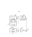
図1は、第1の実施形態のセンサ回路100のブロック図である。
第1の実施形態のセンサ回路100は、物理量検出部10と、クロック発生回路20と、出力ドライバ30と、電位検出回路40と、クロック制御回路50とで構成されている。
Hereinafter, the sensor circuit of the present invention will be described by taking as an example a magnetic switch that outputs a binary value of the result of comparing the output voltage of the Hall element with the reference voltage.
<First Embodiment>
FIG. 1 is a block diagram of the
The
物理量検出部10は、印加される物理量に応じて2つの異なる電位レベルの物理量検出信号12を出力する。
出力ドライバ30は、入力が物理量検出部10の出力に接続され、出力が出力端子31に接続される。出力ドライバ30は、物理量検出部10の物理量検出信号12を反転して、出力端子31にセンサ回路100の出力論理信号32を出力する。
The physical
In the
電位検出回路40は、入力が出力端子31に接続され、出力端子31の電位に基づいて2値の電位検出信号41を出力する。
クロック発生回路20は、物理量検出部10に検出動作を制御するための制御信号21を出力し、休止期間においてクロック制御回路50にサンプリング信号22を出力する。
クロック制御回路50は、電位検出信号41とサンプリング信号22と物理量検出信号12が入力され、クロック発生回路20にモード切替信号51を出力する。
The
The
The
物理量検出部10は、S極またはN極の磁界を検出する磁気スイッチであり、外部から印加された磁束密度の大小に応じて物理量検出信号12の電位レベルを切り替える。また、物理量検出部10は、制御信号21に応じて物理量の検出・解除動作を行う動作期間と、内部回路の動作電流の大部分を遮断する休止期間とを有する間欠駆動を行う。
The physical
クロック制御回路50は、サンプリング信号22に同期して電位検出信号41をサンプリングし、シフトレジスタなどにそのデータを保持する。クロック制御回路50は、電位検出信号41から所定の信号パターン(ここでは、LHHL、HLLHとする)が得られた場合に、モード切替信号51をテストモードに対応するレベルに切り替える。また、クロック制御回路50は、物理量検出信号12が変化すると、モード切替信号51を通常モードに対応するレベルに切り替える。
The
物理量検出部10は、例えば、以下に示す動作をするように構成されている。
物理量検出部10は、制御信号21がHレベルのときに動作期間になり、ホール素子の出力電圧を基準電圧と比較し、制御信号21がLレベルのときに休止期間になり、印加された磁束密度が所定の値より小さいとLレベル、所定の値より大きいとHレベルの物理量検出信号12を出力する。
The physical
The physical
出力ドライバ30は、例えば、CMOSドライバが用いられる。出力ドライバ30は、印加される物理量が小さいとき、例えば、入力である物理量検出信号12がLレベルのとき、NchドライバがオフしPchドライバがオンして、Hレベルの出力論理信号32を出力端子31に出力する。印加される物理量が大きいとき、例えば、入力である物理量検出信号12がHレベルのとき、NchドライバがオンしPchドライバがオフして、Lレベルの出力論理信号32を出力端子31に出力する。
As the
電位検出回路40は、例えば、シュミットトリガ回路や、差動対と基準電圧回路によるコンパレータ等で構成される。電位検出回路40は、出力端子31の電位がHレベルのときにHレベルの電位検出信号41を出力し、出力端子31の電位がLレベルのときにLレベルの電位検出信号41を出力する。
The
次に、第1の実施形態のセンサ回路100の動作について説明する。
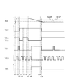
図2は、第1の実施形態のセンサ回路100の動作を示すタイミング図である。
図2において、センサ回路100に印加される磁束密度をBin、物理量検出信号12の電圧をV12、出力端子31の電圧をV31、電位検出信号41の電圧をV41、制御信号21の電圧をV21、サンプリング信号22の電圧をV22、動作周期制御信号51の電圧をV51、とする。また、物理量検出部10が物理量を検出する閾値をBOP、検出を解除する閾値をBRP、とする。
Next, the operation of the
FIG. 2 is a timing diagram showing the operation of the
In FIG. 2, the magnetic flux density applied to the
センサ回路100には、タイミング図に示すような磁束密度Binが印加される。磁束密度Binは、時刻t0以前では閾値BRPより低いので、物理量検出信号12はLレベル、出力端子31及び電位検出信号41の電圧はHレベルである。
A magnetic flux density Bin as shown in the timing diagram is applied to the
センサ回路100は、時刻t1までは通常動作時の休止期間であり、動作周期制御信号51はLレベルを維持して、クロック発生回路20からサンプリング信号22が出力される。時刻t1前までのサンプリング信号22において、クロック制御回路50は、電位検出信号41のHレベルを連続して保持しているので、通常動作(動作周期制御信号51はLレベル)を維持する。ここで、クロック制御回路50は、サンプリング信号22の立ち上がりエッジで電位検出信号41の電位を読み込むものとする。
The
センサ回路100は、時刻t1から時刻t2の間は通常動作時の動作期間であり、クロック発生回路20は制御信号21をHレベルにする。物理量検出部10は、動作期間中に磁束密度Binが閾値BOPより高いことを検出して信号処理を行い、制御信号21がLレベルになったときに物理量検出信号12をHレベルにする。それに応じて、出力端子31及び電位検出信号41の電圧はLレベルになる。そして、センサ回路100は、再び通常動作時の休止期間になり、動作周期制御信号51はLレベルを維持して、クロック発生回路20からサンプリング信号22が出力される。
The
クロック制御回路50は、時刻t3において、サンプリング信号22によって電位検出信号41のLレベルを読み込む。
ここで、時刻t4から時刻t7において、出力端子31に外部から強制的にHレベルを入力されると、クロック制御回路50は、時刻t5、t6において、サンプリング信号22によって電位検出信号41のHレベルを読み込み、更に、時刻t8において、サンプリング信号22によって電位検出信号41のLレベルを読み込む。
The
Here, when the H level is forcibly input to the
従って、クロック制御回路50は、入力された信号パターンがLHHLのレベルになるので、時刻t8から時刻t9の間においてテストモード入力信号であると判断し、通常動作からテストモードに切替え、Hレベルの動作周期制御信号51を出力する。
Therefore, since the input signal pattern reaches the LHHL level, the
センサ回路100は、時刻t10までテストモードを維持した後、磁束密度Binが解除閾値BRP以下となったことを物理量検出部10が検出すると、物理量検出信号12がLレベルに変化する。クロック制御回路50は、物理量検出信号12がLレベルに変化したことを受けて、テストモードから通常動作に切替え、Lレベルの動作周期制御信号51を出力する。
After maintaining the test mode until time t10, the
以上説明したように、本実施形態のセンサ回路100は、通常動作時の休止期間において、出力端子31に外部から強制的に所定の信号パターンを有する電圧を入力して、それを検出することで通常動作からテストモードに切替え、物理量検出信号12のレベルが変化したことを受けて、テストモードから通常動作に切替える構成とした。従って、本実施形態のセンサ回路100は、テストモードに誤って切り替わってしまう可能性が低く、安定した動作が可能である。
As described above, the
なお、図2のタイミング図では、磁束密度Binが検出閾値BOPより高い状態からテストモードに切替える説明をしたが、磁束密度Binが解除閾値BRPより低い状態からテストモードに切替える場合でも同様である。この場合は、出力端子31を強制的にLレベルの電位にして、信号パターンをHLLHとすることで、クロック制御回路50はテストモード入力信号であると判断し、通常動作からテストモードに切替えることが出来る。
また、信号パターンをLHHLやHLLHとして説明したが、これに限らず、更に複雑な信号パターンや短い信号パターンであっても良い。
In the timing diagram of FIG. 2, the state in which the magnetic flux density Bin is higher than the detection threshold BOP is switched to the test mode, but the same applies to the case where the magnetic flux density Bin is switched from the state lower than the release threshold BRP to the test mode. In this case, by forcibly setting the
Further, although the signal pattern has been described as LHHL or HLLH, the present invention is not limited to this, and a more complicated signal pattern or a shorter signal pattern may be used.
<第2の実施形態>
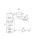
図3は、第2の実施形態のセンサ回路200のブロック図である。第2の実施形態のセンサ回路200は、図1のセンサ回路100に追加してタイムアウト時間を計数するカウンタ60を備えた。また、クロック制御回路50は、カウンタ60が出力するタイムアウト信号61を受ける構成とした。その他の構成については、図1のセンサ回路100と同一であるため、同一の構成要素には同一の符号を付し、説明は省略する。
<Second embodiment>
FIG. 3 is a block diagram of the
カウンタ60は、電位検出回路40から出力される電位検出信号41が入力され、クロック制御回路50にタイムアウト信号61を出力する。クロック制御回路50は、Hレベルのタイムアウト信号61を受けると、サンプリング信号22をマスクする。
The
次に、第2の実施形態のセンサ回路200の動作について説明する。
図4は、第2の実施形態のセンサ回路200の動作を示すタイミング図である。
図4において、タイムアウト信号61の電圧をV61とする。また、図2のタイミング図と同一の動作については、その説明を省略する。
Next, the operation of the
Figure 4 is a view to a timing diagram of the operation of the
In FIG. 4, the voltage of the
時刻t1において、物理量検出信号12はHレベルとなり、出力端子31の電圧はLレベルとなる。
時刻t2において、外部からのノイズが出力端子31に重畳すると、図に示すように電圧V31が変動し、Hレベルの電位検出信号41が出力される。従って、クロック制御回路50は、サンプリング信号22によって電位検出信号41のHレベルを読み込む。
At time t1, the physical
When noise from the outside is superimposed on the
カウンタ60は、電位検出信号41の変動を受けて計数を開始し、時刻t3においてタイムアウト時間に達すると、タイムアウト信号61をLレベルからHレベルにする。クロック制御回路50は、Hレベルのタイムアウト信号61を受けると、サンプリング信号22をマスクするので、時刻4における外部からのノイズによる電位検出信号41のHレベルを読み込まない。
The counter 60 starts counting in response to the fluctuation of the
従って、クロック制御回路50は、時刻t2以降の信号パターンをHLLHと認識しないので、図4のようにノイズがあったとしても、誤ってテストモードに切替えることが無い。
以上説明したように、第2の実施形態のセンサ装置では、タイムアウト信号61を出力するカウンタ60を備えたので、誤ってテストモードに切替えられるという誤動作をより確実に防止できる。
Therefore, since the
As described above, since the sensor device of the second embodiment includes the counter 60 that outputs the
なお、カウンタ60は、フリップフロップによる論理回路を用いたディジタル回路で構成してもよいし、定電流源と容量素子によるアナログ計時回路で構成してもよい。また、タイムアウト信号61は、例えば、時刻t5またはt6において、制御信号21によってHレベルからLレベルにリセットされるようにすれば良い。
The counter 60 may be configured by a digital circuit using a logic circuit using a flip-flop, or may be configured by an analog timekeeping circuit using a constant current source and a capacitive element. Further, the
<第3の実施形態>
図5は、第3の実施形態のセンサ回路300のブロック図である。第3の実施形態のセンサ回路300は、図1のセンサ回路100に追加して制御信号21を受けてデッドタイム信号71を出力するデッドタイム制御回路70を備えた。また、クロック制御回路50は、デッドタイム制御回路70が出力するデッドタイム信号71を受ける構成とした。その他の構成については、図1のセンサ回路100と同一であるため、同一の構成要素には同一の符号を付し、説明は省略する。
<Third embodiment>
FIG. 5 is a block diagram of the
デッドタイム制御回路70は、電位検出信号41が入力され、クロック制御回路50にデッドタイム信号71を出力する。クロック制御回路50は、Hレベルのデッドタイム信号71を受けると、サンプリング信号22をマスクする。
The dead
次に、第3の実施形態のセンサ回路300の動作について説明する。
図6は、第3の実施形態のセンサ回路300の動作を示すタイミング図である。
図6において、デッドタイム信号71の電圧をV71とする。また、図2のタイミング図と同一の動作については、その説明を省略する。
Next, the operation of the
Figure 6 is a view to a timing diagram of the operation of the
In FIG. 6, the voltage of the
時刻t1において、物理量検出信号12はHレベルとなり、出力ドライバ30は出力をLレベルにする。ここで、出力端子31の容量負荷が大きい場合、出力端子31の電圧V31は、出力端子31の容量負荷と出力ドライバ30のオン抵抗で決まる時定数に従って比較的長い時間をかけて静定する。
At time t1, the physical
デッドタイム制御回路70は、制御信号21がHレベルになったことを受けて、すなわち休止期間への遷移後の所定期間、Hレベルのデッドタイム信号71を出力する。クロック制御回路50は、デッドタイム信号71がHレベルを維持する時刻t3まで、サンプリング信号22をマスクしてサンプリング動作を行わない。従って、クロック制御回路50は、時刻t1から時刻t3までの電位検出信号41のHレベルを読み込まない。
The dead
時刻t2において、出力端子31の電圧V31は電位検出回路40の判定閾値Vthを下回るので、電位検出信号41はLレベルになる。よって、デッドタイム信号71がHレベルを維持する時間は、電圧V31が判定閾値Vthを下回る時間より長くすればよい。
At time t2, the voltage V31 of the
従って、クロック制御回路50は、時刻t4において出力端子31にノイズが重畳したとしても、時刻t1以降の信号パターンをHLLHと認識しないので、誤ってテストモードに切替えることが無い。
Therefore, even if noise is superimposed on the
このように第3の実施形態のセンサ回路300は、クロック制御回路50にデッドタイム信号71を出力するデッドタイム制御回路70を備えたので、誤ってテストモードに切替えられるという誤動作をより確実に防止できる。
As described above, the
なお、デッドタイム制御回路70は、フリップフロップによる論理回路で構成してもよいし、定電流源と容量素子と閾値回路による計時回路で構成してもよい。
また、デッドタイム信号71は、制御信号21がHレベルになったことを受けてHレベルを出力すると説明したが、発明の趣旨に合えばどのような信号を起点にしても良い。
The dead
Further, although it has been explained that the
<第4の実施形態>
図7は、第4の実施形態のセンサ回路400のブロック図である。第4の実施形態のセンサ回路400は、図1のセンサ回路100に追加してリセット信号81を出力するリセット回路80を備えた。また、クロック制御回路50は、リセット回路80が出力するリセット信号81を受ける構成とした。その他の構成については、図1のセンサ回路100と同一であるため、同一の構成要素には同一の符号を付し、説明は省略する。
<Fourth Embodiment>
FIG. 7 is a block diagram of the
リセット回路80は、電位検出信号41が入力され、クロック制御回路50へリセット信号81を出力する。クロック制御回路50は、Hレベルのリセット信号81を受けると、信号パターンを保持するシフトレジスタをリセットする。
The
次に、第4の実施形態のセンサ回路400の動作について説明する。
図8は、第4の実施形態のセンサ回路400の動作を示すタイミング図である。
図8において、リセット信号81の電圧をV81とする。また、図2のタイミング図と同一の動作については、その説明を省略する。
Next, the operation of the
Figure 8 is a view to a timing diagram of the operation of the fourth embodiment of the
In FIG. 8, the voltage of the
時刻t1において、物理量検出信号12はHレベルとなり、出力ドライバ30は出力をLレベルにする。リセット信号81は、休止期間になるとLレベルにリセットされる。
時刻t2において、外部からのノイズが出力端子31に重畳すると、図に示すように電圧V31が変動し、Hレベルの電位検出信号41が出力される。従って、クロック制御回路50は、サンプリング信号22によって電位検出信号41のHレベルを読み込む。
At time t1, the physical
When noise from the outside is superimposed on the
ここで、リセット回路80は、電位検出信号41の信号の幅を検出する機能を有する。 例えば、図8の時刻t2のように幅が小さいことを検出すると、例えば時刻t3において、クロック制御回路50へHレベルのリセット信号81を出力する。クロック制御回路50は、Hレベルのリセット信号81を受けると、信号パターンを保持するシフトレジスタをリセットする。即ち、時刻t2でシフトレジスタに読み込まれたHレベルはリセットされる。
従って、時刻t4において、外部からのノイズが出力端子31に重畳したとしても、クロック制御回路50は、電位検出信号41を誤ってHLLHと認識することがなくなる。
Here, the
Therefore, even if noise from the outside is superimposed on the
このように第4の実施形態のセンサ回路400は、クロック制御回路50にリセット信号81を出力するリセット回路80を備えたので、誤ってテストモードに切替えられるという誤動作をより確実に防止できる。
なお、リセット信号81は、図8では、制御信号21がHレベルになったことを受けてLレベルになっているが、例えばワンショットパルスにしても良い。
As described above, since the
In FIG. 8, the
以上説明したように、本発明のセンサ回路は、サンプリング信号22に同期して電位検出信号41をサンプリングするクロック制御回路50と、休止期間においてサンプリング信号22を出力するクロック発生回路20と、を備えたので、誤ってテストモードに切替えられるという誤動作をより確実に防止できる。
As described above, the sensor circuit of the present invention includes a
なお、実施形態において、物理量検出部10を磁気センサ回路としての説明したが、物理量の検出結果を出力端子31から2値信号として出力するような構成であれば、これに制限されるものではない。例えば、物理量検出部10は、温度センサ回路や光センサ回路であってもよい。
In the embodiment, the physical
また、本発明のセンサ回路は、必ずしもこの構成やセンサ素子に制限されるものではなく、発明の趣旨を逸脱しない範囲で様々な変更や組み合わせなどが可能である。例えば、各実施形態の回路を適宜組み合わせても良い。更に、物理量検出部10と出力端子31とクロック制御回路50の組合せを複数備えて、夫々の出力端子に強制的に電圧を印加して、その組み合わせでテストモードに切替えるような構成としても良い。
Further, the sensor circuit of the present invention is not necessarily limited to this configuration and sensor elements, and various changes and combinations can be made without departing from the spirit of the invention. For example, the circuits of each embodiment may be combined as appropriate. Further, a plurality of combinations of the physical
10 物理量検出部
20 クロック発生回路
30 出力ドライバ
31 出力端子
40 電位検出回路
50 クロック制御回路
60 カウンタ
70 デッドタイム制御回路
80 リセット回路
100、200、300、400 センサ回路
10 Physical quantity detector
20
Claims (5)
印加される物理量に応じて2つの異なる電位レベルの物理量検出信号を出力する物理量検出部と、
前記物理量検出信号を受けて論理信号を出力端子へ出力する出力ドライバと、
前記物理量検出部へ前記間欠動作を制御するための制御信号を出力し、前記休止期間にサンプリング信号を出力するクロック発生回路と、
前記出力端子の電位を検出し、検出信号を出力する電位検出回路と、
前記サンプリング信号と前記検出信号が入力され、前記クロック発生回路へモード切替信号を出力するクロック制御回路と、を備え、
前記クロック制御回路は、前記検出信号を前記サンプリング信号に基づきサンプリングしたデータに所定の信号パターンを検出すると、前記クロック発生回路をテストモードに切替えるモード切替信号を出力する
ことを特徴とするセンサ回路。 It is a sensor circuit that performs intermittent operation with an operation period and a pause period.
A physical quantity detection unit that outputs two different potential level physical quantity detection signals according to the applied physical quantity, and a physical quantity detection unit.
An output driver that receives the physical quantity detection signal and outputs a logic signal to the output terminal,
A clock generation circuit that outputs a control signal for controlling the intermittent operation to the physical quantity detection unit and outputs a sampling signal during the pause period.
A potential detection circuit that detects the potential of the output terminal and outputs a detection signal,
A clock control circuit in which the sampling signal and the detection signal are input and a mode switching signal is output to the clock generation circuit is provided.
The clock control circuit is a sensor circuit characterized in that when a predetermined signal pattern is detected in data obtained by sampling the detection signal based on the sampling signal, a mode switching signal for switching the clock generation circuit to a test mode is output.
前記テストモードにおいて前記物理量検出信号が変化すると、通常モードに切替えるモード切替信号を出力する
ことを特徴とする請求項1に記載のセンサ回路。 The clock control circuit is further input with the physical quantity detection signal output by the physical quantity detection unit.
The sensor circuit according to claim 1, wherein when the physical quantity detection signal changes in the test mode, a mode switching signal for switching to the normal mode is output.
前記カウンタは、前記検出信号の変動を受けて計数を開始し、タイムアウト時間に達すると前記クロック制御回路にタイムアウト信号を出力し、
前記クロック制御回路は、前記タイムアウト信号によって前記サンプリング信号をマスクする
ことを特徴とする請求項1または2に記載のセンサ回路。 In addition, it has a counter
The counter starts counting in response to fluctuations in the detection signal, and when the timeout time is reached, outputs a timeout signal to the clock control circuit.
The sensor circuit according to claim 1 or 2, wherein the clock control circuit masks the sampling signal with the timeout signal.
前記デッドタイム制御回路は、前記休止期間への遷移後の所定期間に前記クロック制御回路にデッドタイム信号を出力し、
前記クロック制御回路は、前記デッドタイム信号によって前記サンプリング信号をマスクする
ことを特徴とする請求項1または2に記載のセンサ回路。 In addition, it is equipped with a dead time control circuit.
The dead time control circuit outputs a dead time signal to the clock control circuit during a predetermined period after the transition to the pause period.
The sensor circuit according to claim 1 or 2, wherein the clock control circuit masks the sampling signal with the dead time signal.
前記リセット回路は、前記検出信号の幅が小さいことを検出すると前記クロック制御回路にリセット信号を出力し、
前記クロック制御回路は、前記リセット信号によって前記サンプリング信号をマスクする
ことを特徴とする請求項1または2に記載のセンサ回路。 In addition, it has a reset circuit
When the reset circuit detects that the width of the detection signal is small, the reset circuit outputs a reset signal to the clock control circuit.
The sensor circuit according to claim 1 or 2, wherein the clock control circuit masks the sampling signal with the reset signal.
Priority Applications (4)
| Application Number | Priority Date | Filing Date | Title |
|---|---|---|---|
| TW106127049A TWI701444B (en) | 2016-08-26 | 2017-08-10 | Sensing circuit |
| US15/685,473 US10191124B2 (en) | 2016-08-26 | 2017-08-24 | Sensor circuit |
| KR1020170107292A KR102303877B1 (en) | 2016-08-26 | 2017-08-24 | Sensor circuit |
| CN201710741669.XA CN107783065B (en) | 2016-08-26 | 2017-08-25 | Sensor circuit |
Applications Claiming Priority (2)
| Application Number | Priority Date | Filing Date | Title |
|---|---|---|---|
| JP2016165827 | 2016-08-26 | ||
| JP2016165827 | 2016-08-26 |
Publications (3)
| Publication Number | Publication Date |
|---|---|
| JP2018036252A JP2018036252A (en) | 2018-03-08 |
| JP2018036252A5 JP2018036252A5 (en) | 2020-07-30 |
| JP6883482B2 true JP6883482B2 (en) | 2021-06-09 |
Family
ID=61567306
Family Applications (1)
| Application Number | Title | Priority Date | Filing Date |
|---|---|---|---|
| JP2017132422A Active JP6883482B2 (en) | 2016-08-26 | 2017-07-06 | Sensor circuit |
Country Status (3)
| Country | Link |
|---|---|
| JP (1) | JP6883482B2 (en) |
| KR (1) | KR102303877B1 (en) |
| TW (1) | TWI701444B (en) |
Families Citing this family (2)
| Publication number | Priority date | Publication date | Assignee | Title |
|---|---|---|---|---|
| JP7465173B2 (en) | 2020-08-03 | 2024-04-10 | エイブリック株式会社 | Magnetic Sensor Circuit |
| JP2022153693A (en) | 2021-03-30 | 2022-10-13 | エイブリック株式会社 | sensor device |
Family Cites Families (20)
| Publication number | Priority date | Publication date | Assignee | Title |
|---|---|---|---|---|
| JPS6337270A (en) * | 1986-07-31 | 1988-02-17 | Fujitsu Ltd | Semiconductor device |
| JPH1116395A (en) * | 1997-06-25 | 1999-01-22 | Mitsubishi Electric Corp | Semiconductor memory device |
| TW419592B (en) * | 1998-03-31 | 2001-01-21 | Hitachi Maxell | Current accumulating value detecting apparatus, current detecting apparatus and the battery set used |
| JP3672082B2 (en) | 2000-09-14 | 2005-07-13 | 理研計器株式会社 | Gas detection alarm device using hot-wire gas sensor |
| TW559970B (en) * | 2001-04-05 | 2003-11-01 | Kawasaki Microelectronics Inc | Test circuit, semiconductor product wafer having the test circuit, and method of monitoring manufacturing process using the test circuit |
| JP2006153699A (en) * | 2004-11-30 | 2006-06-15 | Matsushita Electric Ind Co Ltd | Magnetic field detection device |
| US7295051B2 (en) * | 2005-06-15 | 2007-11-13 | Cypress Semiconductor Corp. | System and method for monitoring a power supply level |
| DE102006050832B4 (en) * | 2006-10-27 | 2012-07-26 | Infineon Technologies Ag | In-operation test of a signal path by means of at least two test signals |
| JP4756701B2 (en) | 2006-12-13 | 2011-08-24 | 三洋電機株式会社 | Power supply voltage detection circuit |
| KR20100034030A (en) * | 2007-06-27 | 2010-03-31 | 가부시키가이샤 어드밴티스트 | Detector and tester |
| JP4786608B2 (en) * | 2007-07-30 | 2011-10-05 | パナソニック株式会社 | Magnetic field detector |
| JP2007322442A (en) | 2007-09-07 | 2007-12-13 | Matsushita Electric Ind Co Ltd | Flow measuring device |
| US8120354B2 (en) * | 2008-05-01 | 2012-02-21 | Broadband Discovery Systems, Inc. | Self-calibrating magnetic field monitor |
| JP5206487B2 (en) | 2009-02-25 | 2013-06-12 | 富士通セミコンダクター株式会社 | Semiconductor integrated circuit control method and semiconductor integrated circuit |
| TWI408390B (en) * | 2010-06-25 | 2013-09-11 | Princeton Technology Corp | Controlling circuit used for analog measure module and controlling module thereof |
| KR101254263B1 (en) * | 2010-11-23 | 2013-04-12 | 삼성디스플레이 주식회사 | Power converter, display device including dc-dc converter, system including display device and method of driving display device |
| US8760217B2 (en) * | 2011-02-25 | 2014-06-24 | Qualcomm Incorporated | Semiconductor device having on-chip voltage regulator |
| KR101204205B1 (en) * | 2011-05-13 | 2012-11-26 | 삼성전기주식회사 | Apparatus and method for driving inertial sensor |
| JP5957242B2 (en) | 2012-03-01 | 2016-07-27 | アズビル株式会社 | Ultrasonic flowmeter simple diagnostic device |
| US8943377B2 (en) | 2012-08-15 | 2015-01-27 | International Business Machines Corporation | On-chip detection of types of operations tested by an LBIST |
-
2017
- 2017-07-06 JP JP2017132422A patent/JP6883482B2/en active Active
- 2017-08-10 TW TW106127049A patent/TWI701444B/en active
- 2017-08-24 KR KR1020170107292A patent/KR102303877B1/en active IP Right Grant
Also Published As
| Publication number | Publication date |
|---|---|
| KR20180023852A (en) | 2018-03-07 |
| KR102303877B1 (en) | 2021-09-17 |
| JP2018036252A (en) | 2018-03-08 |
| TW201807417A (en) | 2018-03-01 |
| TWI701444B (en) | 2020-08-11 |
Similar Documents
| Publication | Publication Date | Title |
|---|---|---|
| JP4965387B2 (en) | Magnetic sensor circuit | |
| US7746131B2 (en) | Reset signal filter | |
| KR101445424B1 (en) | Detection circuit and sensor device | |
| CN107783065B (en) | Sensor circuit | |
| JP6883482B2 (en) | Sensor circuit | |
| JP4719190B2 (en) | Binary circuit | |
| KR100309233B1 (en) | Single-end-zero receiver circiut | |
| KR101015785B1 (en) | Devices and methods for detecting contact | |
| CN110398622B (en) | Zero-crossing detection circuit and sensor device | |
| JP2007282182A (en) | Binarization circuit | |
| US9608603B2 (en) | Sampling circuit | |
| JP4942195B2 (en) | Data communication apparatus, data communication system, and data communication method | |
| JP6585977B2 (en) | Semiconductor device and oscillation circuit control method | |
| KR100917999B1 (en) | Devices and methods for sensing touching correctly despite variable environments | |
| JP4955725B2 (en) | Binary circuit | |
| JP2014062825A (en) | Voltage detection circuit, and voltage detection method | |
| JP5059801B2 (en) | Binary circuit | |
| US9111644B2 (en) | Readout circuit and semiconductor device | |
| JP2022153693A5 (en) | ||
| JP2005223837A (en) | Signal-determining device | |
| JP2008311998A (en) | Clock number count circuit | |
| JP2012169850A (en) | Chopper type comparator |
Legal Events
| Date | Code | Title | Description |
|---|---|---|---|
| A521 | Request for written amendment filed |
Free format text: JAPANESE INTERMEDIATE CODE: A523 Effective date: 20200609 |
|
| A621 | Written request for application examination |
Free format text: JAPANESE INTERMEDIATE CODE: A621 Effective date: 20200609 |
|
| A977 | Report on retrieval |
Free format text: JAPANESE INTERMEDIATE CODE: A971007 Effective date: 20210409 |
|
| TRDD | Decision of grant or rejection written | ||
| A01 | Written decision to grant a patent or to grant a registration (utility model) |
Free format text: JAPANESE INTERMEDIATE CODE: A01 Effective date: 20210506 |
|
| A61 | First payment of annual fees (during grant procedure) |
Free format text: JAPANESE INTERMEDIATE CODE: A61 Effective date: 20210510 |
|
| R150 | Certificate of patent or registration of utility model |
Ref document number: 6883482 Country of ref document: JP Free format text: JAPANESE INTERMEDIATE CODE: R150 |
|
| S531 | Written request for registration of change of domicile |
Free format text: JAPANESE INTERMEDIATE CODE: R313531 |
|
| R350 | Written notification of registration of transfer |
Free format text: JAPANESE INTERMEDIATE CODE: R350 |