JP6882861B2 - Semiconductor devices, liquid discharge heads, liquid discharge head cartridges and recording devices - Google Patents
Semiconductor devices, liquid discharge heads, liquid discharge head cartridges and recording devices Download PDFInfo
- Publication number
- JP6882861B2 JP6882861B2 JP2016139695A JP2016139695A JP6882861B2 JP 6882861 B2 JP6882861 B2 JP 6882861B2 JP 2016139695 A JP2016139695 A JP 2016139695A JP 2016139695 A JP2016139695 A JP 2016139695A JP 6882861 B2 JP6882861 B2 JP 6882861B2
- Authority
- JP
- Japan
- Prior art keywords
- discharge
- unit
- transistor
- wiring
- resistance
- Prior art date
- Legal status (The legal status is an assumption and is not a legal conclusion. Google has not performed a legal analysis and makes no representation as to the accuracy of the status listed.)
- Active
Links
Images


Classifications
-
- B—PERFORMING OPERATIONS; TRANSPORTING
- B41—PRINTING; LINING MACHINES; TYPEWRITERS; STAMPS
- B41J—TYPEWRITERS; SELECTIVE PRINTING MECHANISMS, i.e. MECHANISMS PRINTING OTHERWISE THAN FROM A FORME; CORRECTION OF TYPOGRAPHICAL ERRORS
- B41J2/00—Typewriters or selective printing mechanisms characterised by the printing or marking process for which they are designed
- B41J2/005—Typewriters or selective printing mechanisms characterised by the printing or marking process for which they are designed characterised by bringing liquid or particles selectively into contact with a printing material
- B41J2/01—Ink jet
- B41J2/015—Ink jet characterised by the jet generation process
- B41J2/04—Ink jet characterised by the jet generation process generating single droplets or particles on demand
- B41J2/045—Ink jet characterised by the jet generation process generating single droplets or particles on demand by pressure, e.g. electromechanical transducers
- B41J2/04501—Control methods or devices therefor, e.g. driver circuits, control circuits
- B41J2/04541—Specific driving circuit
-
- B—PERFORMING OPERATIONS; TRANSPORTING
- B41—PRINTING; LINING MACHINES; TYPEWRITERS; STAMPS
- B41J—TYPEWRITERS; SELECTIVE PRINTING MECHANISMS, i.e. MECHANISMS PRINTING OTHERWISE THAN FROM A FORME; CORRECTION OF TYPOGRAPHICAL ERRORS
- B41J2/00—Typewriters or selective printing mechanisms characterised by the printing or marking process for which they are designed
- B41J2/005—Typewriters or selective printing mechanisms characterised by the printing or marking process for which they are designed characterised by bringing liquid or particles selectively into contact with a printing material
- B41J2/01—Ink jet
- B41J2/015—Ink jet characterised by the jet generation process
- B41J2/04—Ink jet characterised by the jet generation process generating single droplets or particles on demand
- B41J2/045—Ink jet characterised by the jet generation process generating single droplets or particles on demand by pressure, e.g. electromechanical transducers
- B41J2/04501—Control methods or devices therefor, e.g. driver circuits, control circuits
- B41J2/04548—Details of power line section of control circuit
-
- B—PERFORMING OPERATIONS; TRANSPORTING
- B41—PRINTING; LINING MACHINES; TYPEWRITERS; STAMPS
- B41J—TYPEWRITERS; SELECTIVE PRINTING MECHANISMS, i.e. MECHANISMS PRINTING OTHERWISE THAN FROM A FORME; CORRECTION OF TYPOGRAPHICAL ERRORS
- B41J2/00—Typewriters or selective printing mechanisms characterised by the printing or marking process for which they are designed
- B41J2/005—Typewriters or selective printing mechanisms characterised by the printing or marking process for which they are designed characterised by bringing liquid or particles selectively into contact with a printing material
- B41J2/01—Ink jet
- B41J2/015—Ink jet characterised by the jet generation process
- B41J2/04—Ink jet characterised by the jet generation process generating single droplets or particles on demand
- B41J2/045—Ink jet characterised by the jet generation process generating single droplets or particles on demand by pressure, e.g. electromechanical transducers
- B41J2/04501—Control methods or devices therefor, e.g. driver circuits, control circuits
- B41J2/0458—Control methods or devices therefor, e.g. driver circuits, control circuits controlling heads based on heating elements forming bubbles
-
- B—PERFORMING OPERATIONS; TRANSPORTING
- B41—PRINTING; LINING MACHINES; TYPEWRITERS; STAMPS
- B41J—TYPEWRITERS; SELECTIVE PRINTING MECHANISMS, i.e. MECHANISMS PRINTING OTHERWISE THAN FROM A FORME; CORRECTION OF TYPOGRAPHICAL ERRORS
- B41J2/00—Typewriters or selective printing mechanisms characterised by the printing or marking process for which they are designed
- B41J2/005—Typewriters or selective printing mechanisms characterised by the printing or marking process for which they are designed characterised by bringing liquid or particles selectively into contact with a printing material
- B41J2/01—Ink jet
- B41J2/015—Ink jet characterised by the jet generation process
- B41J2/04—Ink jet characterised by the jet generation process generating single droplets or particles on demand
- B41J2/045—Ink jet characterised by the jet generation process generating single droplets or particles on demand by pressure, e.g. electromechanical transducers
- B41J2/04501—Control methods or devices therefor, e.g. driver circuits, control circuits
- B41J2/04581—Control methods or devices therefor, e.g. driver circuits, control circuits controlling heads based on piezoelectric elements
-
- B—PERFORMING OPERATIONS; TRANSPORTING
- B41—PRINTING; LINING MACHINES; TYPEWRITERS; STAMPS
- B41J—TYPEWRITERS; SELECTIVE PRINTING MECHANISMS, i.e. MECHANISMS PRINTING OTHERWISE THAN FROM A FORME; CORRECTION OF TYPOGRAPHICAL ERRORS
- B41J2/00—Typewriters or selective printing mechanisms characterised by the printing or marking process for which they are designed
- B41J2/005—Typewriters or selective printing mechanisms characterised by the printing or marking process for which they are designed characterised by bringing liquid or particles selectively into contact with a printing material
- B41J2/01—Ink jet
- B41J2/015—Ink jet characterised by the jet generation process
- B41J2/04—Ink jet characterised by the jet generation process generating single droplets or particles on demand
- B41J2/045—Ink jet characterised by the jet generation process generating single droplets or particles on demand by pressure, e.g. electromechanical transducers
- B41J2/04501—Control methods or devices therefor, e.g. driver circuits, control circuits
- B41J2/04586—Control methods or devices therefor, e.g. driver circuits, control circuits controlling heads of a type not covered by groups B41J2/04575 - B41J2/04585, or of an undefined type
-
- H—ELECTRICITY
- H01—ELECTRIC ELEMENTS
- H01L—SEMICONDUCTOR DEVICES NOT COVERED BY CLASS H10
- H01L27/00—Devices consisting of a plurality of semiconductor or other solid-state components formed in or on a common substrate
- H01L27/02—Devices consisting of a plurality of semiconductor or other solid-state components formed in or on a common substrate including semiconductor components specially adapted for rectifying, oscillating, amplifying or switching and having at least one potential-jump barrier or surface barrier; including integrated passive circuit elements with at least one potential-jump barrier or surface barrier
- H01L27/04—Devices consisting of a plurality of semiconductor or other solid-state components formed in or on a common substrate including semiconductor components specially adapted for rectifying, oscillating, amplifying or switching and having at least one potential-jump barrier or surface barrier; including integrated passive circuit elements with at least one potential-jump barrier or surface barrier the substrate being a semiconductor body
- H01L27/08—Devices consisting of a plurality of semiconductor or other solid-state components formed in or on a common substrate including semiconductor components specially adapted for rectifying, oscillating, amplifying or switching and having at least one potential-jump barrier or surface barrier; including integrated passive circuit elements with at least one potential-jump barrier or surface barrier the substrate being a semiconductor body including only semiconductor components of a single kind
- H01L27/085—Devices consisting of a plurality of semiconductor or other solid-state components formed in or on a common substrate including semiconductor components specially adapted for rectifying, oscillating, amplifying or switching and having at least one potential-jump barrier or surface barrier; including integrated passive circuit elements with at least one potential-jump barrier or surface barrier the substrate being a semiconductor body including only semiconductor components of a single kind including field-effect components only
- H01L27/088—Devices consisting of a plurality of semiconductor or other solid-state components formed in or on a common substrate including semiconductor components specially adapted for rectifying, oscillating, amplifying or switching and having at least one potential-jump barrier or surface barrier; including integrated passive circuit elements with at least one potential-jump barrier or surface barrier the substrate being a semiconductor body including only semiconductor components of a single kind including field-effect components only the components being field-effect transistors with insulated gate
-
- H—ELECTRICITY
- H01—ELECTRIC ELEMENTS
- H01L—SEMICONDUCTOR DEVICES NOT COVERED BY CLASS H10
- H01L23/00—Details of semiconductor or other solid state devices
- H01L23/52—Arrangements for conducting electric current within the device in operation from one component to another, i.e. interconnections, e.g. wires, lead frames
- H01L23/522—Arrangements for conducting electric current within the device in operation from one component to another, i.e. interconnections, e.g. wires, lead frames including external interconnections consisting of a multilayer structure of conductive and insulating layers inseparably formed on the semiconductor body
- H01L23/528—Geometry or layout of the interconnection structure
-
- H—ELECTRICITY
- H01—ELECTRIC ELEMENTS
- H01L—SEMICONDUCTOR DEVICES NOT COVERED BY CLASS H10
- H01L27/00—Devices consisting of a plurality of semiconductor or other solid-state components formed in or on a common substrate
- H01L27/02—Devices consisting of a plurality of semiconductor or other solid-state components formed in or on a common substrate including semiconductor components specially adapted for rectifying, oscillating, amplifying or switching and having at least one potential-jump barrier or surface barrier; including integrated passive circuit elements with at least one potential-jump barrier or surface barrier
- H01L27/04—Devices consisting of a plurality of semiconductor or other solid-state components formed in or on a common substrate including semiconductor components specially adapted for rectifying, oscillating, amplifying or switching and having at least one potential-jump barrier or surface barrier; including integrated passive circuit elements with at least one potential-jump barrier or surface barrier the substrate being a semiconductor body
- H01L27/08—Devices consisting of a plurality of semiconductor or other solid-state components formed in or on a common substrate including semiconductor components specially adapted for rectifying, oscillating, amplifying or switching and having at least one potential-jump barrier or surface barrier; including integrated passive circuit elements with at least one potential-jump barrier or surface barrier the substrate being a semiconductor body including only semiconductor components of a single kind
- H01L27/085—Devices consisting of a plurality of semiconductor or other solid-state components formed in or on a common substrate including semiconductor components specially adapted for rectifying, oscillating, amplifying or switching and having at least one potential-jump barrier or surface barrier; including integrated passive circuit elements with at least one potential-jump barrier or surface barrier the substrate being a semiconductor body including only semiconductor components of a single kind including field-effect components only
- H01L27/088—Devices consisting of a plurality of semiconductor or other solid-state components formed in or on a common substrate including semiconductor components specially adapted for rectifying, oscillating, amplifying or switching and having at least one potential-jump barrier or surface barrier; including integrated passive circuit elements with at least one potential-jump barrier or surface barrier the substrate being a semiconductor body including only semiconductor components of a single kind including field-effect components only the components being field-effect transistors with insulated gate
- H01L27/092—Devices consisting of a plurality of semiconductor or other solid-state components formed in or on a common substrate including semiconductor components specially adapted for rectifying, oscillating, amplifying or switching and having at least one potential-jump barrier or surface barrier; including integrated passive circuit elements with at least one potential-jump barrier or surface barrier the substrate being a semiconductor body including only semiconductor components of a single kind including field-effect components only the components being field-effect transistors with insulated gate complementary MIS field-effect transistors
- H01L27/0922—Combination of complementary transistors having a different structure, e.g. stacked CMOS, high-voltage and low-voltage CMOS
Description
本発明は、半導体装置、液体吐出ヘッド、液体吐出ヘッドカートリッジおよび記録装置に関する。 The present invention relates to semiconductor devices, liquid discharge heads, liquid discharge head cartridges and recording devices.
吐出素子で発生したエネルギを液体に与えることによって、液体を吐出口から吐出させる液体吐出ヘッドが知られている。記録の高速化を実現するために、液体吐出ヘッドには複数の吐出素子が配される。それぞれの吐出素子に印加される電圧がばらついた場合、吐出される液体の量がばらつき、形成される画像の画質が低下しうる。特許文献1には、液体吐出ヘッドに配された複数の吐出素子に電力を供給する際、端子部から吐出素子までの配線長に応じて変化する配線抵抗によって、それぞれの吐出素子に印加される電圧がばらつくことを低減する配線パターンが示されている。具体的には、電源配線と接地配線との接続部を両端に配し、電源配線および接地配線の配線幅を徐々に変更することが記載されている。
A liquid discharge head that discharges a liquid from a discharge port by applying the energy generated by the discharge element to the liquid is known. A plurality of discharge elements are arranged in the liquid discharge head in order to realize high-speed recording. If the voltage applied to each discharge element varies, the amount of liquid discharged varies, and the image quality of the formed image may deteriorate. In
電源配線用と接地配線用との端子部を片側に配置したいなど、レイアウト上の制約のために、配線パターンによって吐出素子に印加される電圧のばらつきを低減することが難しい場合が考えられる。本発明は、吐出素子に供給する電圧のばらつきを低減しながら、配線や端子部のレイアウトの制約を緩和するのに有利な技術を提供することを目的とする。 It may be difficult to reduce the variation in the voltage applied to the discharge element depending on the wiring pattern due to layout restrictions such as arranging the terminal portions for the power supply wiring and the ground wiring on one side. An object of the present invention is to provide a technique advantageous for alleviating restrictions on the layout of wiring and terminal portions while reducing variations in the voltage supplied to the discharge element.
上記課題に鑑みて、本発明の実施形態に係る半導体装置は、液体を吐出するための吐出素子と、吐出素子を駆動するための駆動部と、をそれぞれ有する複数の吐出ユニットと、複数の吐出ユニットのそれぞれに配線を介して電源を供給するための端子部と、を含み、複数の吐出ユニットは、第1吐出ユニットと第2吐出ユニットとを含み、第1吐出ユニットは、吐出素子のうち第1吐出素子と、駆動部のうち第1駆動部と、を有し、第2吐出ユニットは、吐出素子のうち第2吐出素子と、駆動部のうち第2駆動部と、を有し、端子部から第1吐出ユニットまでの電流経路の長さは、端子部から前記第2吐出ユニットまでの電流経路の長さよりも大きく、第1駆動部の抵抗は、第2駆動部の抵抗よりも小さく、端子部は、電源端子と接地端子とを含み、第1駆動部は、第1トランジスタ及び第3トランジスタを含み、第2駆動部は、第2トランジスタ及び第4トランジスタを含み、第1吐出ユニットは、一端と他端との間で第1トランジスタ、第1吐出素子、第3トランジスタの順で直列に接続され、第2吐出ユニットは、一端と他端との間で第2トランジスタ、第2吐出素子、第4トランジスタの順で直列に接続され、第1吐出ユニットの一端と第2吐出ユニットの一端とが接続され、第1吐出ユニットの他端と第2吐出ユニットの他端とが接続され、第1駆動部の抵抗は、第1トランジスタおよび第3トランジスタのオン抵抗であり、第2駆動部の抵抗は、第2トランジスタおよび第4トランジスタのオン抵抗であり、第1トランジスタのオン抵抗が第2トランジスタのオン抵抗よりも小さく、第3トランジスタのオン抵抗が第4トランジスタのオン抵抗よりも小さいことを特徴とする。 In view of the above problems, the semiconductor device according to the embodiment of the present invention has a plurality of discharge units each having a discharge element for discharging a liquid and a drive unit for driving the discharge element, and a plurality of discharge units. Each of the units includes a terminal portion for supplying power via wiring, a plurality of discharge units include a first discharge unit and a second discharge unit, and the first discharge unit is one of the discharge elements. It has a first discharge element and a first drive unit among the drive units, and the second discharge unit has a second discharge element among the discharge elements and a second drive unit among the drive units. The length of the current path from the terminal portion to the first discharge unit is larger than the length of the current path from the terminal portion to the second discharge unit, and the resistance of the first drive unit is larger than the resistance of the second drive unit. rather small, the terminal portion includes a power terminal and a ground terminal, the first drive unit includes a first transistor and the third transistor, the second drive unit includes a second transistor and a fourth transistor, a first The discharge unit is connected in series between one end and the other end in the order of the first transistor, the first discharge element, and the third transistor, and the second discharge unit is the second transistor between one end and the other end. The second discharge element and the fourth transistor are connected in series in this order, one end of the first discharge unit and one end of the second discharge unit are connected, and the other end of the first discharge unit and the other end of the second discharge unit. The resistance of the first drive unit is the on-resistance of the first transistor and the third transistor, and the resistance of the second drive unit is the on-resistance of the second transistor and the fourth transistor. low on-resistance than the on resistance of the second transistor, the on resistance of the third transistor and said smaller Ikoto than the on resistance of the fourth transistor.
上記手段によって、吐出素子に供給する電圧のばらつきを低減しながら、配線や端子部のレイアウトの制約を緩和するのに有利な技術が提供される。 The above means provides an advantageous technique for alleviating restrictions on the layout of wiring and terminal portions while reducing variations in the voltage supplied to the discharge element.
以下、本発明に係る半導体装置の具体的な実施形態を、添付図面を参照して説明する。なお、以下の説明および図面において、複数の図面に渡って共通の構成については共通の符号を付している。そのため、複数の図面を相互に参照して共通する構成を説明し、共通の符号を付した構成については適宜説明を省略する。 Hereinafter, specific embodiments of the semiconductor device according to the present invention will be described with reference to the accompanying drawings. In the following description and drawings, common reference numerals are given to common configurations across a plurality of drawings. Therefore, a common configuration will be described with reference to each other of the plurality of drawings, and the description of the configuration with a common reference numeral will be omitted as appropriate.
第1の実施形態
図1〜4を参照して、本発明の実施形態による半導体装置の構造について説明する。図1は、本発明の第1の実施形態における半導体装置100の回路構成を示す図である。半導体装置100は、液体の吐出を制御するように構成される。半導体装置100は、例えば、インクなどの液体によって紙などの媒体に画像を記録する記録装置において、吐出口からの液体の吐出を制御するように構成されうる。
First Embodiment With reference to FIGS. 1 to 4, the structure of the semiconductor device according to the embodiment of the present invention will be described. FIG. 1 is a diagram showing a circuit configuration of a
半導体装置100は、電源端子106(VH端子)および接地端子107(GNDH端子)を備える端子部Tと、複数の吐出ユニットUNITと、電源配線104(VH配線)と、接地配線105(GNDH配線)と、を備えている。電源端子106および接地端子107は、電源配線104および接地配線105を介して、それぞれの吐出ユニットUNITに電力を供給する。また、半導体装置100は、複数の吐出ユニットUNITをそれぞれ制御する複数の制御回路103(典型的にはロジック回路)を備えうる。制御回路103は、外部からの信号(不図示)によってそれぞれの吐出ユニットUNITを制御しうる。それぞれの吐出ユニットUNITは、インクなどの液体に対して、該液体が吐出口から吐出するように、エネルギを印加する吐出素子101と、吐出素子101を駆動するための駆動部102とを含みうる。それぞれの吐出ユニットUNITは、一端と他端とがそれぞれ電源配線104と接地配線105と接続され、一端と他端との間で吐出素子101と駆動部102とは直列に接続される。ここで、吐出素子101は、例えば、ヒータなどの発熱体やピエゾ素子などの圧電素子であり、液体を吐出するためのエネルギを発生しうる。図1に示す構成において、吐出素子101は発熱体であり、回路図において抵抗として表される。駆動部102は、吐出素子101に対する電気的エネルギの印加を制御する回路素子でありうる。駆動部102は、例えば、パワートランジスタなどの、電流を制御可能なトランジスタでありうる。図1には、駆動部102としてn型のトランジスタ(パワートランジスタ)が例示されている。制御回路103の出力が、駆動部102のトランジスタのゲート電極に接続され、駆動部102を制御する。
The
図2に、半導体装置100の吐出素子101、駆動部102、制御回路103、電源配線104、接地配線105、電源端子106、接地端子107を含む各構成の配置例を示す。半導体装置100は、典型的には、シリコン基板などを用いた基板(半導体基板)の上に多層配線技術を用いて形成される。電源配線104は、例えば、第2層の金属配線(例えば、アルミニウムなどの金属またはその合金などで構成されうる)で、駆動部102の上を通るように形成されうる。電源配線104は、電源端子106から延びていて、それぞれの吐出ユニットUNITに電源電圧を供給する。接地配線105は、例えば、電源配線104と同じ第2層の金属配線(例えば、アルミニウムなどの金属またはその合金などで構成されうる)で、制御回路103の上を通るように形成されうる。接地配線105は、接地端子107から延びていて、それぞれの吐出ユニットUNITに接地電圧を供給する。電源配線104および接地配線105は、典型的には、一定の厚さを有する。電源端子106および接地端子107を含む端子部Tは、それぞれの吐出ユニットUNITの配列における一端に配置されている。図2に示す構成において、端子部Tよりも左の側に複数の吐出ユニットUNITがそれぞれ配される。また、図2に示す構成において、半導体装置100には、16の吐出ユニットUNITが配されるが、15以下であってもよいし、17以上であってもよい。
FIG. 2 shows an arrangement example of each configuration including the
半導体装置100において、端子部Tから遠い吐出ユニットUNITの駆動部102が吐出素子101を駆動する際の抵抗が、端子部Tから近い吐出ユニットUNITの駆動部102が吐出素子101を駆動する際の抵抗よりも小さくなるようにレイアウトされる。例えば、端子部Tから吐出ユニットUNITのそれぞれまでの距離が遠くなるに従って、吐出ユニットUNITのそれぞれに含まれる駆動部102が吐出素子101を駆動する際の抵抗が小さくなるようにレイアウトされる。駆動部102が吐出素子101を駆動する際の抵抗は、連続的に小さくなってもよいし、段階的に小さくなってもよい。複数の吐出ユニットUNITのそれぞれに含まれる駆動部102は、それぞれトランジスタを有する。駆動部102の抵抗とは、駆動部102が対応する吐出素子101を駆動する際の抵抗であり、それぞれの駆動部102が有するトランジスタのオン抵抗RONである。そこで、例えば、吐出ユニットUNITに含まれる駆動部102に用いられるトランジスタは、端子部Tから離れて配されるにつれて、連続的または段階的にチャネル幅W(ゲート幅)が大きくなるようにレイアウトされる。このようなレイアウトを用いることによって、端子部Tに近い駆動部102の抵抗であるトランジスタのオン抵抗RONが、当該駆動部102よりも端子部Tから遠い駆動部102のトランジスタのオン抵抗RON以上となる。本明細書において、オン抵抗RONとは、駆動部102のトランジスタのドレイン−ソース間の電位差とドレイン電流量とで算出される抵抗値のことを示す。
In the
次に、駆動部102の吐出素子101を駆動させる際の駆動部102の抵抗について、電源端子106と吐出ユニットUNITのそれぞれとの間の寄生抵抗および吐出ユニットUNITのそれぞれと接地端子107との間の寄生抵抗と共に説明する。電源端子106と吐出ユニットUNITのそれぞれとの間の寄生抵抗は、電源配線104の配線抵抗RVHを含む。図1に示すように、例えば端子部Tの電源端子106から吐出ユニットUNIT1までの間には配線抵抗RVHとして抵抗Rv(1)が存在する。また、電源端子106から吐出ユニットUNIT2までの間には配線抵抗RVHとして抵抗Rv(1)および抵抗Rv(2)が存在し、電源端子106から吐出ユニットUNITiまでの間には配線抵抗RVHとして抵抗ΣRv(i)が存在する。ここで、抵抗Rv(1)は電源端子106と吐出ユニットUNIT1との間の電源配線104の配線抵抗、また、抵抗Rv(i)(i≧2)とは、吐出ユニットUNIT(i)と吐出ユニットUNIT(i−1)との間の電源配線104の配線抵抗を示す。同様に、吐出ユニットUNITのそれぞれと接地端子107との間の寄生抵抗は、接地配線105の配線抵抗RGNDHを含み、例えば端子部Tの接地端子107から吐出ユニットUNIT1までの間には配線抵抗RGNDHとして抵抗Rg(1)が存在する。また、接地端子107から吐出ユニットUNIT2までの間には配線抵抗RGNDHとして抵抗Rg(1)および抵抗Rg(2)が存在し、接地端子107から吐出ユニットUNITiの間には配線抵抗RGNDHとして抵抗ΣRg(i)が存在する。ここで、抵抗Rg(1)は接地端子107と吐出ユニットUNIT1との間の接地配線105の配線抵抗、また、抵抗Rg(i)(i≧2)とは、吐出ユニットUNIT(i)と吐出ユニットUNIT(i−1)との間の接地配線105の配線抵抗を示す。
Next, regarding the resistance of the
このため、端子部Tから遠い吐出ユニットUNITは、端子部Tに近い吐出ユニットUNITと比較して、電源端子106から吐出ユニットUNITを介して接地端子107までの電流経路に含まれる配線抵抗の抵抗値が大きくなる。このため、吐出ユニットUNITが動作する際、端子部Tから遠い吐出ユニットUNITに印加される電圧が、端子部Tに近い吐出ユニットUNITに印加される電圧よりも低くなり、吐出ユニットUNIT間で印加される電圧がばらついてしまう。それぞれの吐出ユニットUNITの間で印加される電圧がばらつくと、それぞれの吐出ユニットUNITに含まれる吐出素子101に印加される電圧がばらつく。このため、吐出素子101によって吐出される液体の量がばらつき、形成される画像の画質が低下しうる。
Therefore, the discharge unit UNIT far from the terminal portion T has a resistance of the wiring resistance included in the current path from the
そこで、本実施形態において、駆動部102のうち、端子部Tからの距離がより大きい駆動部102のトランジスタのオン抵抗RONが、端子部Tからの距離がより小さい駆動部102のトラジスタのオン抵抗RONより小さくなるよう、駆動部102を構成する。例えば、端子部Tからの距離に応じて駆動部102のトランジスタのオン抵抗RONが、端子部Tから遠いほど連続的または段階的に小さくなるようにしてもよい。これによって、配線抵抗RVH、RGNDHを含む寄生抵抗の抵抗値とオン抵抗RONの抵抗値との合計の抵抗値のばらつきが、吐出ユニットUNITのそれぞれに同じトランジスタを用いた場合の抵抗値のばらつきと比較して低減される。これによって、それぞれの吐出ユニットUNITに含まれる吐出素子101に印加される電圧のばらつきが低減される。結果として、吐出素子101によって吐出される液体の量のばらつきが低減され、形成される画像の画質が向上しうる。
Therefore, in the present embodiment, among the
具体的には、吐出素子101が、図1に示すように第1吐出素子101−1と、印加される電圧が第1吐出素子101−1よりも大きい第2吐出素子101−2を有する場合を考える。この場合、第1吐出素子101−1の駆動部102−1の抵抗を第2吐出素子101−2の駆動部102−2の抵抗よりも小さくする。例えば、端子部(電源端子106)から第1吐出素子101−1を有する吐出ユニットまでの電流経路の抵抗が、該端子部から第2吐出素子101−2を有する第2吐出ユニットまでの電流経路の抵抗より大きい場合がある。図1に示す構成では、吐出ユニットUNIT15に含まれる吐出素子101を第1吐出素子101−1、吐出ユニットUNIT3に含まれる吐出素子101を第2吐出素子101−2としたが、組み合わせはこれに限られない。第1吐出素子101−1よりも第2吐出素子101−2に印加される電圧が大きくなる組み合わせであればよい。
Specifically, when the
この場合、第1駆動部102−1の抵抗が、第2駆動部102−2の抵抗よりも小さくなるようする。例えば、電源端子106から第1吐出素子101−1までの電流経路に配されるトランジスタと、電源端子106から第2吐出素子101−2までの電流経路に配されるトランジスタの、オン抵抗を異ならせる。具体的には、第1吐出素子101−1に接続されるトランジスタ121−1のオン抵抗を、第2吐出素子101−2に接続されるトランジスタ121−2のオン抵抗より小さくする。
In this case, the resistance of the first drive unit 102-1 is set to be smaller than the resistance of the second drive unit 102-2. For example, if the on-resistance of the transistor arranged in the current path from the
このように構成することで、第1吐出素子101−1と第2吐出素子101−2に印加される電圧の差をなくす、または、低減することができる。端子部Tから吐出素子までの電流経路に複数のトラジスタが配される場合は、トランジスタのオン抵抗の和で調整することができる。 With this configuration, the difference in voltage applied to the first discharge element 101-1 and the second discharge element 101-2 can be eliminated or reduced. When a plurality of transistors are arranged in the current path from the terminal portion T to the discharge element, the sum of the on-resistances of the transistors can be used for adjustment.
また、吐出ユニットUNITの吐出素子101それぞれに対応する電流経路ごとに直列に挿入される抵抗値のばらつきが低減されることによって、吐出素子101を流れる電流値のばらつきが低減する。結果として、それぞれの吐出素子101での発熱量のばらつきが低減され、特定の吐出素子101の短寿命化を抑制できる。また、端子部Tに近い駆動部102のトランジスタは、端子部Tから遠い駆動部102のトランジスタよりも駆動能力が小さく(抵抗が大きく)てもよい。このため、チャネル幅Wが小さく相対的に小さいトランジスタを用いることができ、結果として半導体装置100の面積の利用効率を向上することが可能となる。
Further, by reducing the variation in the resistance value inserted in series for each current path corresponding to each of the
図2の半導体装置100では、吐出ユニットUNITが配される領域の片側に隣り合うように電源端子106及び接地端子107を含む端子部Tが配されている。この場合、電源配線104及び接地配線105の幅で、それぞれの吐出ユニットUNITに対する抵抗値を一定にすると、端子部T側に比べ、端子部Tから遠い側の端部における電源配線104及び接地配線105の幅が非常に大きくなる。一方、本実施形態の構成を用いることで、端子部Tを片側に設けても、トランジスタのオン抵抗RONによって、配線抵抗による吐出ユニットUNITに印加される電圧のばらつきを低減できるため、配線幅を変更する必要がない。よって、吐出素子に供給する電圧のばらつきを低減しながら、配線や端子部Tのレイアウトの制約を緩和することができる。
In the
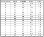
例えば、図3に示すように吐出ユニットUNITごとに、電源配線104の配線抵抗RVHと接地配線105の配線抵抗RGNDHと駆動部102のトランジスタのオン抵抗RONとの合計の抵抗値が一定となるように、それぞれのトランジスタを配してもよい。図3に示す構成の場合、トランジスタのオン抵抗RONは、端子部Tに近い吐出ユニットUNIT1のトランジスタの14.25Ωから、端子部Tから遠い吐出ユニットUNIT16のトランジスタの12Ωまで連続的に変化する。トランジスタにおいて、オン抵抗RONとチャネル幅Wとは、他の構成が同じ場合、互いに反比例の関係にある。このため、吐出ユニットUNIT16のトランジスタのチャネル幅Wは、他の構成が同じ場合、吐出ユニットUNIT1のトランジスタのチャネル幅の14.25/12の大きさでありうる。
For example, as shown in FIG. 3, the total resistance value of the wiring resistance RVH of the
また、図3に示す構成では、配線抵抗RVH、RGNDHと駆動部102のトランジスタのオン抵抗RONとの合計の抵抗値が一定となるように、連続的に駆動部102のトランジスタのオン抵抗を変化させたが、これに限られることはない。例えば、複数の吐出ユニットUNITを1つのグループとし、グループごとに段階的に駆動部102のトランジスタのオン抵抗RONを変化させてもよい。それぞれの吐出ユニットUNITの駆動部102に同じトランジスタを用いた場合と比較して、吐出ユニットUNITのそれぞれの間で、配線抵抗RVH、RGNDHを含む寄生抵抗とオン抵抗RONとの合計の抵抗値のばらつきが低減できればよい。
Further, in the configuration shown in FIG. 3, the on-resistance of the transistor of the
また、駆動部102のトランジスタの抵抗(オン抵抗RON)を変化させるのに用いるのは、トランジスタのチャネル幅Wの変化に限られるものではない。例えば、駆動部102のトランジスタのチャネル長Lを変化させることによって抵抗を変化させてもよい。ここで、注目する吐出ユニットUNITの駆動部102のトランジスタのチャネル幅WをW1、チャネル長LをL1とする。また、注目する吐出ユニットUNITよりも端子部Tから遠い駆動部102のトランジスタのチャネル幅WをW2、チャネル長LをL2とする。この場合、W1/L1<W2/L2の関係を満たすことによって、それぞれの吐出ユニットUNITの吐出素子101に印加される電圧がばらつくことを低減できる。
Further, what is used to change the resistance (ON resistance RON) of the transistor of the
また例えば、駆動部102のトランジスタにチャネル幅W、チャネル長Lが同じトランジスタを用いた場合、吐出素子101を駆動させる際、駆動部102のトランジスタに印加されるゲート電圧Vgsを変化させてもよい。この場合、吐出ユニットUNITのトランジスタに印加するゲート電圧Vgsを、端子部Tから該吐出ユニットUNITまでの距離よりも、端子部Tからの距離が小さい吐出ユニットUNITのトランジスタに印加されるゲート電圧Vgsよりも大きくする。例えば、端子部Tから吐出ユニットUNITのそれぞれまでの距離が遠くなるに従って、吐出ユニットUNITのそれぞれに含まれるトランジスタに印加するゲート電圧Vgsを、連続的または段階的に大きくする。これによって、それぞれの吐出ユニットUNITの吐出素子101に印加される電圧がばらつくことを低減できる。また、それぞれの吐出ユニットUNITの駆動部102のそれぞれのトランジスタのチャネル幅W、チャネル長L、ゲート電圧Vgsの変化を組み合わせて用いてもよい。
Further, for example, when a transistor having the same channel width W and channel length L is used for the transistor of the
図4は、図1に示した半導体装置100の回路構成の変形例を示す図である。図1に示す構成では、吐出素子101が1つのトランジスタで構成される駆動部102によって駆動される回路構成を示したが、これに限られるものではなく、駆動部102が、複数のトランジスタによって構成されてもよい。図4に示す構成において、駆動部102は、トランジスタ121とトランジスタ122とを含む。また、それぞれの吐出ユニットUNITは、電源配線104の側から接地配線105の側に向かい、n型のトランジスタ121、吐出素子101、p型のトランジスタ122の順に配される。制御回路103の出力が、駆動部102のトランジスタ121、122のゲート電極にそれぞれ接続される。このような構成の駆動部102を、電圧補償型駆動部と呼ぶ。これ以外の構成は、図1に示す構成と同じであってもよい。
FIG. 4 is a diagram showing a modified example of the circuit configuration of the
電圧補償型駆動部は、トランジスタ121とトランジスタ122とを飽和領域で動作するように設計されうる。一方、上述と同様に、それぞれの吐出ユニットUNITの配される位置に応じて、電源配線104および接地配線105の配線抵抗を含む寄生抵抗の違いから、吐出ユニットUNITに配されるトランジスタ121、122のソース・ドレイン電圧が異なる。このため、トランジスタ121、122の大きさをすべての吐出ユニットUNITで同じにした場合、チャネル長変調効果によって、吐出素子101に印加される電圧がばらついてしまう。これを補正するために、駆動部102の抵抗を異ならせる。
The voltage-compensated drive unit can be designed so that the transistor 121 and the
具体的には、吐出素子101が、図4に示すように第1吐出素子101−1と、印加される電圧が第1吐出素子101−1よりも大きい第2吐出素子101−2を有する場合を考える。この場合、第1吐出素子101−1の第1駆動部102−1の抵抗を第2吐出素子101−2の第2駆動部102−2の抵抗よりも小さくする。例えば、端子部(電源端子106)から第1吐出素子101−1を有する吐出ユニットまでの電流経路の抵抗が、該端子部から第2吐出素子101−2を有する第2吐出ユニットまでの電流経路の抵抗より大きい場合がある。
Specifically, when the
この場合、第1駆動部102−1の抵抗が、第2駆動部102−2の抵抗よりも小さくなるようする。例えば、電源端子106から第1吐出素子101−1までの電流経路に配されるトランジスタと、電源端子106から第2吐出素子101−2までの電流経路に配されるトランジスタの、オン抵抗を異ならせる。具体的には、第1吐出素子101−1に接続されるトランジスタ121−1のオン抵抗を、第2吐出素子101−2に接続されるトランジスタ121−2のオン抵抗よりも小さくする。
In this case, the resistance of the first drive unit 102-1 is set to be smaller than the resistance of the second drive unit 102-2. For example, if the on-resistance of the transistor arranged in the current path from the
このように構成することで、第1吐出素子101−1と第2吐出素子101−2に印加される電圧の差をなくす、または、低減することができる。端子部Tから吐出素子までの電流経路に複数のトラジスタが配される場合は、トランジスタのオン抵抗の和で調整することができる。 With this configuration, the difference in voltage applied to the first discharge element 101-1 and the second discharge element 101-2 can be eliminated or reduced. When a plurality of transistors are arranged in the current path from the terminal portion T to the discharge element, the sum of the on-resistances of the transistors can be used for adjustment.
また、端子部(接地端子107)から第1吐出素子101−1を有する吐出ユニットの電流経路の抵抗が、該端子部から第2吐出素子101−2を有する第2吐出ユニットまでの電流経路の抵抗より大きい場合がある。 Further, the resistance of the current path of the discharge unit having the first discharge element 101-1 from the terminal portion (ground terminal 107) is the resistance of the current path from the terminal portion to the second discharge unit having the second discharge element 101-2. May be greater than resistance.
この場合、第1駆動部102−1の抵抗が、第2駆動部102−2の抵抗よりも小さくなるようにする。例えば、接地端子107から第1吐出素子101−1までの電流経路に配されるトランジスタと、接地端子107から第2吐出素子101−2までの電流経路に配されるトランジスタの、オン抵抗を異ならせる。具体的には、第1吐出素子101−1に接続されるトランジスタ122−1のオン抵抗を、第2吐出素子101−2に接続されるトランジスタ122−2のオン抵抗より小さくする。
In this case, the resistance of the first drive unit 102-1 is set to be smaller than the resistance of the second drive unit 102-2. For example, if the on-resistance of the transistor arranged in the current path from the
このように構成することで、第1吐出素子101−1と第2吐出素子101−2に印加される電圧の差をなくす、または、低減することができる。 With this configuration, the difference in voltage applied to the first discharge element 101-1 and the second discharge element 101-2 can be eliminated or reduced.
トランジスタ121、122のオン抵抗を異ならせるため、例えば、それぞれのトランジスタ121、122のサイズを異ならせる。電圧補償型駆動部においても、オン抵抗は、駆動部102のトランジスタのドレイン−ソース間電圧とドレイン電流量の関数である。
In order to make the on-resistance of the
駆動能力の大きいトランジスタは、駆動能力の小さなトランジスタと比較して、所定のドレイン電流を流すソース・ドレイン間電圧が小さいため、例えば、端子部Tから遠い吐出ユニットUNITに含まれるトランジスタほど、チャネル幅Wを大きくしてもよい。また例えば、端子部Tから遠い吐出ユニットUNITに含まれるトランジスタほど、チャネル長Lを小さくしてもよい。また例えば、駆動部102のトランジスタ121、122にチャネル幅W、チャネル長Lが同じトランジスタを用いた場合、吐出素子101を駆動させる際、駆動部102のトランジスタ121、122に印加されるゲート電圧Vgsを変化させてもよい。この場合、注目する吐出ユニットUNITの駆動部102のトランジスタ121、122のゲート電圧を、注目する吐出ユニットUNITよりも端子部Tから遠い駆動部102のトランジスタ121、122のゲート電圧以下にする。上述の実施形態と同様に、端子部Tからの距離に応じて駆動部102のトランジスタ121、122のオン抵抗RONが、端子部Tから遠いほど連続的または段階的に小さくなるようにする。これによって、それぞれの吐出ユニットUNITの吐出素子101に印加される電圧がばらつくことを低減できる。
A transistor having a large drive capacity has a smaller source-drain voltage through which a predetermined drain current flows than a transistor having a small drive capacity. Therefore, for example, a transistor included in a discharge unit UNIT farther from the terminal portion T has a channel width. W may be increased. Further, for example, the channel length L may be made smaller as the transistor is included in the discharge unit UNIT farther from the terminal portion T. Further, for example, when transistors having the same channel width W and channel length L are used for the
また、図2では、電源端子106及び接地端子107を吐出ユニットUNITが配される領域の片側に配置する例を示したが、本実施形態の半導体装置100はこれに限定されない。例えば、電源端子106が吐出ユニットUNITが配される領域の両側に配され、かつ接地端子107も吐出ユニットUNITが配される領域の両側に配される構成としてもよい。この場合、電源配線104及び接地配線105における配線抵抗は、吐出ユニットUNITが配される領域の中央に向かって大きくなる。よって、駆動部102のトランジスタのオン抵抗RONを中央に向かって小さくすることで、それぞれの吐出ユニットUNITの吐出素子101に印加される電圧のばらつきを低減することができる。このように、本実施形態の半導体装置100を用いることで、配線や端子部のレイアウトの制限を緩和しながら、それぞれの吐出素子101に印加される電圧のばらつきを低減することができる。
Further, although FIG. 2 shows an example in which the
第2の実施形態
図5〜7を参照して、本発明の実施形態による半導体装置の構造について説明する。図5は、本発明の第2の実施形態における半導体装置100の回路構成を示す図である。本実施形態において、互いに隣接する4つの吐出ユニットUNITを1つのセグメント(吐出ユニット群)とする。吐出ユニットUNITは、電源端子106に並列に接続される電源配線104(本実施形態において電源配線104a、104b、104c、104d。)、接地端子107に並列に接続される接地配線105(本実施形態において、接地配線105a、105b、105c、105d。)によって、セグメントごとに電源端子106、接地端子107に接続される。それ以外の構成は、上述の第1の実施形態と同じであってもよい。
The structure of the semiconductor device according to the embodiment of the present invention will be described with reference to FIGS. 5 to 7. FIG. 5 is a diagram showing a circuit configuration of the
図6に、半導体装置100の吐出素子101、駆動部102、制御回路103、電源配線104a〜104d、接地配線105a〜105d、電源端子106、接地端子107を含む各構成の配置例を示す。本実施形態において、半導体装置100は、4つの吐出ユニットUNITを1つのセグメントとし、4つのセグメントが配される。セグメント1は電源配線104a、セグメント2は電源配線104b、セグメント3は電源配線104c、セグメント4は電源配線104dを介して、それぞれ電源端子106から電源電圧が供給される。また、セグメント1は接地配線105a、セグメント2は接地配線105b、セグメント3は接地配線105c、セグメント4は接地配線105dを介して、それぞれ接地端子107から接地電圧が供給される。本実施形態においても、上述の第1の実施形態と同様に、吐出ユニットUNITが配される領域の片側に隣り合うように電源端子106及び接地端子107を含む端子部Tが配される。
FIG. 6 shows an arrangement example of each configuration including the
半導体装置100は、典型的には、シリコン基板などを用いた基板(半導体基板)の上に多層配線技術を用いて形成される。電源配線104a〜104dは、例えば、第2層の金属配線(例えば、アルミニウムなどの金属またはその合金などで構成されうる)で、駆動部102の上を通るように形成されうる。接地配線105a〜105dは、例えば、電源配線104a〜104dと同じ第2層の金属配線(例えば、アルミニウムなどの金属またはその合金などで構成されうる)で、制御回路103の上を通るように形成されうる。電源配線104および接地配線105は、例えば、一定の厚さを有する。図6に示す構成において、半導体装置100には、1つのセグメントに4つの吐出ユニットUNITが配されるが、1つのセグメントに配される吐出ユニットUNITは、1〜3であってもよいし、5以上であってもよい。また、図6に示す構成において、半導体装置100には、4つのセグメントが配されるが、2または3であってもよいし、5以上であってもよい。また例えば、セグメントごとに配される吐出ユニットUNITの数が異なっていてもよい。
The
本実施形態において、端子部Tから遠いセグメントに接続される電源配線104の単位長さあたりの平均の配線抵抗が、端子部Tから近いセグメントに接続される電源配線104の単位長さあたりの平均の配線抵抗よりも小さくなるようにレイアウトされる。また、同様に端子部Tから遠いセグメントに接続される接地配線105の単位長さあたりの平均の配線抵抗が、端子部Tから近いセグメントに接続される接地配線105の単位長さあたりの平均の配線抵抗よりも小さくなるようにレイアウトされる。例えば、電源配線104a〜104dおよび接地配線105a〜105dは、端子部Tから接続するセグメントまでの距離が遠くなるに従って、単位長さあたりの平均の配線抵抗が連続的または段階的に小さくなるように配されてもよい。これを実現するために、例えば、端子部Tに近いセグメントに接続する配線の配線パターンの線幅が、端子部Tから遠いセグメントに接続する配線の配線パターンの線幅以下になるように形成されてもよい。また例えば、端子部Tに近いセグメントに接続する配線の配線パターンの平均の線幅が、端子部Tから遠いセグメントに接続する配線の配線パターンの平均の線幅以下であってもよい。
In the present embodiment, the average wiring resistance per unit length of the
また、第1の実施形態と同様に端子部Tから吐出ユニットUNITまでの距離が遠くなるに従って、吐出ユニットUNITのそれぞれに含まれる駆動部102が吐出素子101を駆動する際の抵抗が、連続的または段階的に小さくなるようにレイアウトされる。図6に示す構成において、セグメントごとに駆動部102として用いるトランジスタのチャネル幅Wを変化させることによって、トランジスタのオン抵抗RONを変化させ、結果として、駆動部102の駆動時の抵抗を変化させる。
Further, as the distance from the terminal portion T to the discharge unit UNIT increases as in the first embodiment, the resistance when the
セグメント間で配線抵抗の大小のばらつきを低減するために、端子部Tに近いセグメント1に接続する配線の配線パターンを細くして抵抗値を大きくし、端子部Tから遠いセグメント4に接続する配線の配線パターンを太くし抵抗値を小さくすることが有効である。しかしながら、一般的に配線パターンは、加工精度などの観点から形成可能な線幅の最小幅が決まりうる。また、線幅の最大幅も半導体装置100のレイアウト全体の大きさなどによって制限がありうる。配線パターンの最小幅、最大幅に制限がある場合、それぞれのセグメント間で、配線抵抗RVH、RGNDHの抵抗値は一定とならず、ばらついてしまう。このため、同じ大きさのトランジスタを駆動部102に用いた場合、吐出素子101に印加される電圧が、セグメントごとにばらつきうる。そこで、吐出ユニットUNITに含まれる駆動部102に、端子部Tから該吐出ユニットUNITまでの距離よりも端子部Tからの距離が小さいセグメントの吐出ユニットUNITに含まれる駆動部102よりも小さいオン抵抗RONを有するトランジスタを用いる。これによって、吐出ユニットUNITの吐出素子101それぞれに対応する電流経路ごとに直列に挿入される抵抗値のばらつきが低減され、吐出素子101に印加される電圧のばらつきが低減される。
In order to reduce the variation in wiring resistance between segments, the wiring pattern of the wiring connected to the
これによって、配線や端子部のレイアウトの制約により、配線パターンでは吐出素子101に印加される電圧のばらつきを低減しきれない場合であっても、吐出素子101に印加される電圧のばらつきを、より効果的に低減することができる。
As a result, even if the wiring pattern cannot completely reduce the variation in the voltage applied to the
また、配線の幅のみで、吐出素子101に印加される電圧のばらつきを低減しようとした場合、該電圧の違いを低減するための配線幅が、加工精度等の観点から形成可能な最小幅より小さくなることがある。この場合、配線幅を最小値より小さくすることはできないため、最も吐出素子101に印加される電圧が最も大きな配線の配線幅を最小値とし、他の配線幅が決定する必要がある。
Further, when it is attempted to reduce the variation in the voltage applied to the
一方、本実施形態では、駆動部102に用いるトランジスタのオン抵抗RONの値も、吐出素子101に印加される電圧のばらつきの低減に用いることができる。このため、配線や端子部Tのレイアウトの制限を緩和しながら、それぞれの吐出素子101に印加される電圧のばらつきを低減することができる。
On the other hand, in the present embodiment, the value of the on-resistance RON of the transistor used in the
例えば、図7に示すように、セグメントごとに、電源配線104a〜104dの配線抵抗RVHと接地配線105a〜105dの配線抵抗RGNDHと駆動部102のトランジスタのオン抵抗RONとの合計の抵抗値が互いに同じとなるようしてもよい。また、本実施形態ではセグメントごとに駆動部102のトランジスタのオン抵抗RONを変化させたが、セグメント内で、さらに駆動部102のトランジスタのオン抵抗RONを変化させてもよい。駆動部102のトランジスタのオン抵抗RONは、第1の実施形態と同様に、チャネル幅Wやチャネル長L、ゲート電圧Vgsを適宜選択することによって調整することができる。
For example, as shown in FIG. 7, the total resistance value of the wiring resistance RVH of the
また、端子部Tに近いセグメントの駆動部102のトランジスタは、端子部Tから遠いセグメントの駆動部102のトランジスタよりも駆動能力が小さく(抵抗が大きく)てもよい。このため、チャネル幅Wを変化させることによって抵抗を調整する場合、端子部Tに近いセグメントのトランジスタは、端子部Tから遠いセグメントの駆動部102のトランジスタよりも相対的にチャネル幅Wの小さいトランジスタを用いることができる。このため、第1の実施形態と同様に半導体装置100の面積の利用効率が向上できる。
Further, the transistor of the
第3の実施形態
図8〜12を参照して、本発明の実施形態による半導体装置の構造について説明する。図8は、本発明の第3の実施形態における半導体装置100の回路構成を示す図である。本実施形態において、複数の吐出ユニットUNITが、上述の第1の実施形態および第2の実施形態と異なり1次元方向だけでなく、行列状に配される。また、それぞれの吐出ユニットUNITに電源端子106から電源電圧を供給する電源配線104および接地端子107から接地電圧を供給する接地配線105がそれぞれ格子状に配される。それ以外の構成は、上述の第1の実施形態と同じであってもよい。
Third Embodiment The structure of the semiconductor device according to the embodiment of the present invention will be described with reference to FIGS. 8 to 12. FIG. 8 is a diagram showing a circuit configuration of the
図9に、半導体装置100の吐出素子101、駆動部102、電源配線104、接地配線105、電源端子106、接地端子107を含む各構成の配置例を示す。図9において、説明を簡単にするために制御回路103は省略している。半導体装置100は、例えば、シリコン基板などを用いた基板303(半導体基板)の上に多層配線技術を用いて形成される。基板303には、吐出素子101および駆動部102をそれぞれ含む複数の吐出ユニットUNITが行列状に配される。また、基板303の上には、吐出素子101に液体を供給する液体供給口304が配される。
FIG. 9 shows an arrangement example of each configuration including the
ここで、図9の縦方向を列方向311(第1の方向)、列方向311と交差する横方向を行方向312(第2の方向)と呼ぶ。吐出ユニットUNITは、列方向311および行方向312に平行にそれぞれ複数配される。基板303は、列方向311に平行な辺307(第1の辺)と辺308(第2の辺)とを備え、また、行方向312に平行な辺305(第3の辺)と辺306(第4の辺)とを備える。互いに隣接する辺同士は、図9に示すように、互いにつながっていてもよいし、直線形状や円弧形状などの面取り部を介してつながっていてもよい。辺305と辺307との間の内角(頂点301)は鈍角であり、辺305と辺308との間の内角(頂点302)は鋭角である。また例えば、面取り部を介して互いに隣接する辺同士がつながる場合、辺305の延長線と辺307の延長線との間の内角は鈍角であり、辺305の延長線と辺308の延長線との間の内角は鋭角である。本実施形態において、辺305、306と辺307、308とは直交せず、平行四辺形の基板303を用いる。しかしながら、基板303の形状はこれに限られることはなく、例えば、辺305、306と辺307、308とが直交した矩形であってもよい。
Here, the vertical direction of FIG. 9 is referred to as a column direction 311 (first direction), and the horizontal direction intersecting the
辺305に近接して、電源配線104に接続する電源端子106および接地配線105に接続する接地端子107がそれぞれ配される。電源端子106および接地端子107を含む端子部Tは、辺305と吐出ユニットUNITの配される領域との間に配される。本実施形態においても、上述の各実施形態と同様に、吐出ユニットUNITが配される領域の片側に隣り合うように電源端子106及び接地端子107を含む端子部Tが配される。半導体装置100の外部に配された電源(不図示)から電源端子106および接地端子107に、電源電圧および接地電圧をそれぞれ供給することによって、電源配線104および接地配線105を介してそれぞれの吐出ユニットUNITに電力が供給される。
A
本実施形態において、複数の吐出ユニットUNITは、端子部Tと辺306との間かつ辺307と辺308との間に、4行32列それぞれ並んで配される。また、液体供給口304は、2つの吐出素子101ごとに1つが配される。このため、液体供給口304は行方向312に密に並びうる。吐出ユニットUNITの配される数は、4行32列に限られることはなく、4行32列未満であってもよいし、4行32列よりも多くてもよい。また、液体供給口304をそれぞれの吐出素子101ごとに配してもよいし、液体供給口を3つ以上の吐出素子101ごとに配してもよい。
In the present embodiment, the plurality of discharge units UNIT are arranged side by side in 4 rows and 32 columns between the terminal portion T and the
電源配線104は、例えば、第2層の金属配線(例えば、アルミニウムなどの金属またはその合金などで構成されうる)で、それぞれの吐出ユニットUNITの上を通るように形成されうる。また、接地配線105は、例えば、第3層の金属配線(例えば、アルミニウムなどの金属またはその合金などで構成されうる)で、それぞれの吐出ユニットUNITの上を通るように形成されうる。電源配線104および接地配線105は、典型的には、一定の厚さを有しうる。
The
電源配線104および接地配線105の配線抵抗を低減するために、本実施形態では配線を基板上の全体に配する。このため、電源配線104および接地配線105は、多層配線構造となり、互いに積層するように配される。また、電源配線104および接地配線105は、液体供給口304を避けて配される。液体供給口304は、吐出素子101に対応し4行16列、設けられることから、電源配線104および接地配線105の配線パターンは、それぞれ格子状の配線パターンになりうる。
In order to reduce the wiring resistance of the
ここで、それぞれの吐出ユニットを、端子部Tの配された側(辺305の側)から順に1行目の吐出ユニットUNIT、2行目の吐出ユニットUNIT・・・と呼ぶ。図9に示す構成において、辺306に最も近接する吐出ユニットUNITは、4行目の吐出ユニットとなる。また、辺307の側から順に1列目の吐出ユニットUNIT、2列目の吐出ユニットUNIT・・・と呼ぶ。図9に示す構成において、辺308に最も近接する吐出ユニットUNITは、32列目の吐出ユニットとなる。
Here, each discharge unit is referred to as a discharge unit UNIT in the first row, a discharge unit UNIT in the second row, and so on in order from the side where the terminal portion T is arranged (the side of the side 305). In the configuration shown in FIG. 9, the discharge unit UNIT closest to the
図9において、1行目の吐出ユニットUNITの配される領域を領域A、2行目の吐出ユニットUNITの配される領域を領域B、3行目および4行目の吐出ユニットUNITの配される領域を領域Cとする。本実施形態において、電源配線104および接地配線105の配線抵抗RVH、RGNDHを考慮し、領域A〜Cで駆動部102の抵抗を変化させる。具体的には、端子部Tから距離の大きい行に配される駆動部102のトランジスタのオン抵抗RONが、端子部Tから距離の小さい行に配される駆動部102のトランジスタのオン抵抗RONよりも小さくなるようにレイアウトする。例えば、図10に示すように、駆動部102のトランジスタのオン抵抗RONが、端子部Tから離れるにしたがって、領域A、B、Cの順に段階的に行ごとに小さくなるようにする。また、行方向312に配された吐出ユニットUNITは、互いに同じオン抵抗RONを有しうる。これによって、電源配線104および接地配線105の配線抵抗と駆動部102のトランジスタのオン抵抗RONとの合計の抵抗値の最大値と最小値との差を小さくすることが可能となり、それぞれの吐出素子101に印加される電圧のばらつきが低減される。本実施形態では、3つの領域に分け、それぞれの駆動部102のトランジスタの抵抗を変化させ駆動能力を変化させたが、これに限られることはない。例えば、1行目および2行目の吐出ユニットUNITで1つの領域、3行目および4行目の吐出ユニットUNITで1つの領域をそれぞれ構成し、領域ごとに駆動部102のトランジスタの抵抗を変化させてもよい。また例えば、行ごとに駆動部102のトランジスタの抵抗を変化させてもよい。
In FIG. 9, the area where the discharge unit UNIT in the first row is arranged is the area A, the area where the discharge unit UNIT in the second row is arranged is the area B, and the discharge unit UNIT in the third and fourth rows is arranged. Let the region C be the region. In the present embodiment, the wiring resistances RVH and RGNDH of the
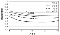
図11に、領域A、B、Cの順に駆動部102のトランジスタのオン抵抗RONを小さくした場合の、電源配線104および接地配線105の配線抵抗RVH、RGNDHと駆動部102のトランジスタのオン抵抗RONとの抵抗値の合計を示す。横軸は列番号、縦軸は抵抗値であり、行ごとに抵抗値の合計を示している。図11より、抵抗値の合計の最大値と最小値との差が0.24Ωであることが分かる。一方、図12に本実施形態に対する比較構造として、すべての駆動部102に同じトランジスタを用いた場合の電源配線104および接地配線105の配線抵抗RVH、RGNDHと駆動部102のトランジスタのオン抵抗RONとの抵抗値の合計を示す。図11と同様に、横軸は列番号、縦軸は抵抗値であり、行ごとに抵抗値の合計を示している。抵抗値の合計の最大値と最小値との差が0.39Ωとなり、本実施形態の0.24Ωよりも大きい抵抗値を示す。本実施形態に示す構成を用いることによって、従来構造と比較して、電源端子106と接地端子107との間の吐出ユニットUNITごとの電流経路に挿入される配線抵抗RVH、RGNDHやトランジスタのON抵抗の和のばらつきを低減することができる。これによって、吐出素子101に印加される電圧のばらつきが低減され、形成される画像の画質が向上しうる。
In FIG. 11, when the on-resistance RON of the transistor of the
このように、それぞれの吐出素子101に印加される電圧がばらつくような配線形状や電源端子、接地端子の配置を有するレイアウトの場合でも、駆動部102のトランジスタのオン抵抗RONによって、ばらつきを低減することができる。例えば、図9に示すような格子状の配線や辺305側のみに電源端子106および接地端子107を配する構成を採用することができる。これによって、本実施形態の半導体装置100において、吐出素子101に印加される電圧のばらつきを低減しつつ、配線や端子部のレイアウトの制約を緩和することができる。
In this way, even in the case of a layout having a wiring shape and arrangement of a power supply terminal and a ground terminal so that the voltage applied to each
また、本実施形態において、駆動部102に用いるトランジスタの抵抗を変化させるためにトランジスタのサイズを変更している。駆動部102のトランジスタのオン抵抗RONが大きい領域では、チャネル幅Wを小さくできるため、駆動部102のトランジスタの形成領域を小さくできる。この結果、領域Aおよび領域Bにおいて、比較構造よりも行方向312に並ぶ吐出ユニットUNIT同士の距離を詰めることが可能となる。結果として、上述の各実施形態と同様に、半導体装置100の小型化が実現できる。また上述の各実施形態と同様に、配線抵抗RVH、RGNDHの抵抗値が小さい領域に配された吐出素子101に多くの電流が流れることを抑制し、特定の吐出素子101の発熱量が大きくなり短寿命化することを抑制できる。
Further, in the present embodiment, the size of the transistor is changed in order to change the resistance of the transistor used for the
第4の実施形態
図13〜15を参照して、本発明の実施形態による半導体装置の構造について説明する。図13は、本発明の第4の実施形態における半導体装置100の各構成の配置例を示す図である。本実施形態において、駆動部102のトランジスタの駆動能力を行方向312だけでなく、列方向311においても変化させることが、上述の第3の実施形態と異なる。その他の構成は、上述の第3の実施形態と同じであってもよい。
Fourth Embodiment The structure of the semiconductor device according to the embodiment of the present invention will be described with reference to FIGS. 13 to 15. FIG. 13 is a diagram showing an arrangement example of each configuration of the
図13において、1列目〜4列目の吐出ユニットUNITが配される領域を領域3、5列目〜8列目の吐出ユニットUNITが配される領域を領域2、9列目〜32列目の吐出ユニットUNITが配される領域を領域1とする。本実施形態において、電源配線104および接地配線105の配線抵抗RVH、RGNDHを考慮し、領域A〜Cおよび領域1〜3の組み合わされる領域ごとに駆動部102の抵抗を変化させる。具体的には、辺307からの距離が小さくかつ辺305からの距離が大きい駆動部102のトランジスタのオン抵抗が、辺307からの距離が小さくかつ辺305からの距離が大きい駆動部102のトランジスタのオン抵抗よりも小さくなるようにレイアウトする。例えば、図14に示すように、駆動部102のトランジスタのオン抵抗RONが、領域A、B、Cの順に段階的に小さくなるようにする。また、図13に示されるような、平行四辺形の基板303を用いた場合、端子部Tから列方向311に離れるに従って配線抵抗の抵抗値が上昇するのに加えて、端子部Tの配された辺305と鈍角の内角(頂点301)を構成する辺307付近で配線抵抗が大きくなる。このため、図14に示すように領域1、2、3の順に駆動部102のトランジスタのオン抵抗RONが段階的に小さくなるようにする。換言すると、辺307から吐出ユニットUNITまでの距離が遠くなるに従って、駆動部102のトランジスタのオン抵抗RONが連続的または段階的に大きくなる。
In FIG. 13, the area where the discharge unit UNITs in the first to fourth rows are arranged is the
駆動部102のトランジスタのオン抵抗RONを変化させる方法は、上述と各実施形態と同様に、チャネル幅Wやチャネル長Lを変化させることによって駆動能力を変化させてもよい。また、駆動部102のトランジスタにチャネル幅W、チャネル長Lが同じトランジスタを用いた場合、吐出素子101を駆動させる際、駆動部102のトランジスタに印加されるゲート電圧Vgsを変化させてもよい。
The method of changing the on-resistance RON of the transistor of the
列方向311だけでなく行方向312においても、駆動部102のトランジスタの駆動能力を変化させる。この構成によって、図15に示すように、電源配線104および接地配線105の配線抵抗RVH、RGNDHと駆動部102のトランジスタのオン抵抗RONとの抵抗値の合計の最大値と最小値との差が0.14Ωまで低減できる。本実施形態に示す構成を用いることによって、上述の第3の実施形態と比較して、電源端子106と接地端子107との間の吐出ユニットUNITごとの電流経路に挿入される配線抵抗やトランジスタのON抵抗の和のばらつきをさらに低減することができる。これによって、吐出素子101に印加される電圧のばらつきが低減され、形成される画像の画質がさらに向上しうる。
The driving ability of the transistor of the
以上、本発明に係る実施形態を4形態示したが、本発明はこれらの実施形態に限定されないことはいうまでもなく、本発明の要旨を逸脱しない範囲で、上述した実施形態は適宜変更、組み合わせが可能である。 Although the four embodiments according to the present invention have been shown above, it goes without saying that the present invention is not limited to these embodiments, and the above-described embodiments are appropriately modified without departing from the gist of the present invention. Combination is possible.
以下、上述のような半導体装置が組み込まれた記録ヘッド(液体吐出ヘッド)、記録ヘッドカートリッジ(液体吐出ヘッドカートリッジ)およびインクジェット記録装置(記録装置)を例示的に説明する。 Hereinafter, a recording head (liquid discharge head), a recording head cartridge (liquid discharge head cartridge), and an inkjet recording device (recording device) in which the above-mentioned semiconductor device is incorporated will be exemplified.
図16(a)には、第1〜第4の実施形態を通して例示的に説明された半導体装置が組み込まれた記録ヘッド用の基体808を有する記録ヘッド811の主要部が示されている。ここでは、上述した吐出素子101は、発熱部806として描かれている。図16(a)に示されるように、基体808は、複数の吐出口800に連通した液路805を形成するための流路壁部材801と、インク供給口803を有する天板802とを組み付けることにより、記録ヘッド811を構成できる。この場合、インク供給口803から注入されるインクが内部の共通液室804へ蓄えられてそれぞれの液路805へ供給され、その状態で基体808、発熱部806を駆動することで、吐出口800からインクの吐出がなされる。
FIG. 16 (a) shows the main part of the
図16(b)は、このような記録ヘッド811を用いた記録ヘッドカートリッジ810の全体構成を示す図である。記録ヘッドカートリッジ810は、上述した複数の吐出口800を有する記録ヘッド811と、この記録ヘッド811に供給するためのインクを保持するインク容器812と、を備えている。インク容器812は、境界線Kを境に記録ヘッド811に着脱可能に設けられている。記録ヘッドカートリッジ810には、図16(c)に示す記録装置に搭載された時にキャリッジ側からの電気信号を受け取るための電気的コンタクト(不図示)が設けられており、この電気信号によってヒータが駆動される。インク容器812内部には、インクを保持するために繊維質状若しくは多孔質状のインク吸収体が設けられており、これらのインク吸収体によってインクが保持されている。
FIG. 16B is a diagram showing an overall configuration of a
図16(b)に示す記録ヘッドカートリッジ810をインクジェット記録装置本体に装着し、装置本体から記録ヘッド811へ付与される信号をコントロールすることによって、高速記録、高画質記録を実現できるインクジェット記録装置を提供することができる。以下、このような記録ヘッドカートリッジ810を用いたインクジェット記録装置について説明する。
An inkjet recording device capable of achieving high-speed recording and high-quality recording by mounting the
図16(c)は、本発明に係る実施形態のインクジェット記録装置900を示す外観斜視図である。図16(c)において、記録ヘッドカートリッジ810は、駆動モータ901の正逆回転に連動して駆動力伝達ギア902、903を介して回転するリードスクリュー904の螺旋溝921に対して係合するキャリッジ920上に搭載されている。そして、記録ヘッドカートリッジ810は、駆動モータ901の駆動力によってキャリッジ920と共にガイド919に沿って矢印aまたはb方向に往復移動可能となっている。不図示の記録媒体給送装置によってプラテン906上に搬送される記録用紙P用の紙押え板905は、キャリッジ移動方向に沿って記録用紙Pをプラテン906に対して押圧する。
FIG. 16C is an external perspective view showing the
フォトカプラ907、908は、キャリッジ920に設けられたレバー909のフォトカプラ907、908が設けられた領域での存在を確認して駆動モータ901の回転方向の切換等を行うためのホームポジション検知手段である。支持部材910は記録ヘッドカートリッジ810の全面をキャップするキャップ部材911を支持し、吸引手段912はキャップ部材911内を吸引し、キャップ内開口513を介して記録ヘッドカートリッジ810の記録ヘッド811の吸引回復を行う。移動部材915は、クリーニングブレード914を前後方向に移動可能にし、クリーニングブレード914および移動部材915は、本体支持板916に支持されている。クリーニングブレード914は、図示の形態でなく周知のクリーニングブレードが本実施形態にも適用できることは言うまでもない。また、レバー917は、吸引回復の吸引を開始するために設けられ、キャリッジ920と係合するカム918の移動に伴って移動し、駆動モータ901からの駆動力がクラッチ切換等の公知の伝達手段で移動制御される。記録ヘッドカートリッジ810の記録ヘッド811に設けられた発熱部806に信号を付与し、駆動モータ901等の各機構の駆動制御を司る記録制御部(不図示)は、装置本体側に設けられている。
The
上述のような構成のインクジェット記録装置900は、記録媒体給送装置によってプラテン906上に搬送される記録用紙Pに対し、記録ヘッドカートリッジ810の記録ヘッド811が記録用紙Pの全幅にわたって往復移動しながら記録を行うものである。記録ヘッド811は、前述の各実施形態の回路構造を有する半導体装置を用いて製造されているため、高精度で高速な記録が可能となる。
In the
次に、上述した装置の記録制御を実行するための制御回路の構成について説明する。図16(d)はインクジェット記録装置900の制御回路の構成を示すブロック図である。制御回路は、記録信号が入力するインタフェース1700、MPU(マイクロプロセッサ)1701、MPU1701が実行する制御プログラムを格納するプログラムROM1702を備えている。制御回路はまた、各種データ(上記記録信号やヘッドに供給される記録データ等)を保存しておくダイナミック型のRAM(ランダムアクセスメモリ)1703と、記録ヘッド1708に対する記録データの供給制御を行うゲートアレイ1704とを備えている。ゲートアレイ1704は、インタフェース1700、MPU1701、RAM1703間のデータ転送制御も行う。制御回路はまた、記録ヘッド1708を搬送するためのキャリアモータ1710と、記録紙搬送のための搬送モータ1709とを備えている。制御回路はまた、記録ヘッド1708を駆動するヘッドドライバ1705、搬送モータ1709およびキャリアモータ1710をそれぞれ駆動するためのモータドライバ1706、1707を備えている。
Next, the configuration of the control circuit for executing the recording control of the above-described device will be described. FIG. 16D is a block diagram showing a configuration of a control circuit of the
上記制御構成の動作を説明すると、インタフェース1700に記録信号が入るとゲートアレイ1704とMPU1701との間で記録信号がプリント用の記録データに変換される。そして、モータドライバ1706、1707が駆動されるとともに、ヘッドドライバ1705に送られた記録データに従って記録ヘッドが駆動され、印字が行われる。
Explaining the operation of the control configuration, when the recording signal is input to the interface 1700, the recording signal is converted into the recording data for printing between the
本発明は、特にインクジェット記録方式の中でも本出願人の提唱する、熱エネルギを利用してインクを吐出する方式の記録ヘッド、記録装置において、優れた効果をもたらすものである。本発明は、例えば、プリンタ、複写機、ファクシミリ装置等に利用可能である。 The present invention brings about an excellent effect especially in a recording head and a recording device of a method of ejecting ink by utilizing thermal energy, which is proposed by the applicant among inkjet recording methods. The present invention can be used, for example, in printers, copiers, facsimile machines and the like.
100:半導体装置、101:吐出素子、102:駆動部、106:電源端子、107:接地端子、UNIT:吐出ユニット 100: Semiconductor device, 101: Discharge element, 102: Drive unit, 106: Power supply terminal, 107: Ground terminal, UNIT: Discharge unit
Claims (19)
前記複数の吐出ユニットのそれぞれに配線を介して電源を供給するための端子部と、を含み、
前記複数の吐出ユニットは、第1吐出ユニットと第2吐出ユニットとを含み、
前記第1吐出ユニットは、前記吐出素子のうち第1吐出素子と、前記駆動部のうち第1駆動部と、を有し、
前記第2吐出ユニットは、前記吐出素子のうち第2吐出素子と、前記駆動部のうち第2駆動部と、を有し、
前記端子部から前記第1吐出ユニットまでの電流経路の長さは、前記端子部から前記第2吐出ユニットまでの電流経路の長さよりも大きく、
前記第1駆動部の抵抗は、前記第2駆動部の抵抗よりも小さく、
前記端子部は、電源端子と接地端子とを含み、
前記第1駆動部は、第1トランジスタ及び第3トランジスタを含み、
前記第2駆動部は、第2トランジスタ及び第4トランジスタを含み、
前記第1吐出ユニットは、一端と他端との間で前記第1トランジスタ、前記第1吐出素子、前記第3トランジスタの順で直列に接続され、
前記第2吐出ユニットは、一端と他端との間で前記第2トランジスタ、前記第2吐出素子、前記第4トランジスタの順で直列に接続され、
前記第1吐出ユニットの前記一端と前記第2吐出ユニットの前記一端とが接続され、
前記第1吐出ユニットの前記他端と前記第2吐出ユニットの前記他端とが接続され、
前記第1駆動部の抵抗は、前記第1トランジスタおよび前記第3トランジスタのオン抵抗であり、
前記第2駆動部の抵抗は、前記第2トランジスタおよび前記第4トランジスタのオン抵抗であり、
前記第1トランジスタのオン抵抗が前記第2トランジスタのオン抵抗よりも小さく、前記第3トランジスタのオン抵抗が前記第4トランジスタのオン抵抗よりも小さいことを特徴とする半導体装置。 A plurality of discharge units each having a discharge element for discharging a liquid and a drive unit for driving the discharge element.
A terminal portion for supplying power to each of the plurality of discharge units via wiring is included.
The plurality of discharge units include a first discharge unit and a second discharge unit.
The first discharge unit includes a first discharge element among the discharge elements and a first drive unit among the drive units.
The second discharge unit includes a second discharge element among the discharge elements and a second drive unit among the drive units.
The length of the current path from the terminal portion to the first discharge unit is larger than the length of the current path from the terminal portion to the second discharge unit.
The resistance of the first drive unit, rather smaller than the resistance of the second drive unit,
The terminal portion includes a power supply terminal and a ground terminal, and includes a power supply terminal and a ground terminal.
The first drive unit includes a first transistor and a third transistor, and includes the first transistor and the third transistor.
The second drive unit includes a second transistor and a fourth transistor, and includes a second transistor and a fourth transistor.
The first discharge unit is connected in series between one end and the other end in the order of the first transistor, the first discharge element, and the third transistor.
The second discharge unit is connected in series between one end and the other end in the order of the second transistor, the second discharge element, and the fourth transistor.
The one end of the first discharge unit and the one end of the second discharge unit are connected to each other.
The other end of the first discharge unit and the other end of the second discharge unit are connected to each other.
The resistance of the first drive unit is the on-resistance of the first transistor and the third transistor.
The resistance of the second drive unit is the on-resistance of the second transistor and the fourth transistor.
It said first transistor on-resistance of less than the on resistance of the second transistor, the semiconductor device on resistance of the third transistor and said smaller Ikoto than the on resistance of the fourth transistor.
前記第1トランジスタのチャネル幅が前記第2トランジスタのチャネル幅よりも大きい、および、前記第1トランジスタのチャネル長が第2トランジスタのチャネル長よりも小さい、のうち少なくとも一方を満たすことを特徴とする請求項1に記載の半導体装置。 The channel width of the first transistor is larger than the channel width of the second transistor, and the channel length of the first transistor is smaller than the channel length of the second transistor, whichever is satisfied. The semiconductor device according to claim 1.
前記複数の吐出ユニットのそれぞれに配線を介して電源を供給するための端子部と、を含み、 A terminal portion for supplying power to each of the plurality of discharge units via wiring is included.
前記複数の吐出ユニットは、第1吐出ユニットと第2吐出ユニットとを含み、 The plurality of discharge units include a first discharge unit and a second discharge unit.
前記第1吐出ユニットは、前記吐出素子のうち第1吐出素子と、前記駆動部のうち第1駆動部と、を有し、 The first discharge unit includes a first discharge element among the discharge elements and a first drive unit among the drive units.
前記第2吐出ユニットは、前記吐出素子のうち第2吐出素子と、前記駆動部のうち第2駆動部と、を有し、 The second discharge unit includes a second discharge element among the discharge elements and a second drive unit among the drive units.
前記端子部から前記第1吐出ユニットまでの電流経路の長さは、前記端子部から前記第2吐出ユニットまでの電流経路の長さよりも大きく、 The length of the current path from the terminal portion to the first discharge unit is larger than the length of the current path from the terminal portion to the second discharge unit.
前記第1駆動部の抵抗は、前記第2駆動部の抵抗よりも小さく、 The resistance of the first drive unit is smaller than the resistance of the second drive unit.
前記端子部は、電源端子と接地端子とを含み、 The terminal portion includes a power supply terminal and a ground terminal, and includes a power supply terminal and a ground terminal.
前記第1駆動部は、第1トランジスタを含み、 The first drive unit includes a first transistor.
前記第2駆動部は、第2トランジスタを含み、 The second drive unit includes a second transistor and includes a second transistor.
前記第1吐出ユニットは、一端と他端との間で前記第1駆動部と前記第1吐出素子とが直列に接続され、 In the first discharge unit, the first drive unit and the first discharge element are connected in series between one end and the other end.
前記第2吐出ユニットは、一端と他端との間で前記第2駆動部と前記第2吐出素子とが直列に接続され、 In the second discharge unit, the second drive unit and the second discharge element are connected in series between one end and the other end.
前記第1駆動部の抵抗は、前記第1トランジスタのオン抵抗であり、 The resistance of the first drive unit is the on-resistance of the first transistor, and is
前記第2駆動部の抵抗は、前記第2トランジスタのオン抵抗であり、 The resistance of the second drive unit is the on-resistance of the second transistor, and is
前記第1トランジスタおよび前記第2トランジスタにおいて、 In the first transistor and the second transistor,
前記第1トランジスタのチャネル幅が前記第2トランジスタのチャネル幅よりも大きい、および、前記第1トランジスタのチャネル長が第2トランジスタのチャネル長よりも小さい、のうち少なくとも一方を満たすことを特徴とする半導体装置。 The channel width of the first transistor is larger than the channel width of the second transistor, and the channel length of the first transistor is smaller than the channel length of the second transistor, whichever is satisfied. Semiconductor device.
前記第1トランジスタに印加されるゲート電圧が、前記第2トランジスタに印加されるゲート電圧よりも大きいことを特徴とする請求項1乃至3の何れか1項に記載の半導体装置。 The semiconductor device according to any one of claims 1 to 3, wherein the gate voltage applied to the first transistor is larger than the gate voltage applied to the second transistor.
前記配線が、前記電源端子と前記複数の吐出ユニット群のうち何れかの吐出ユニット群に含まれる吐出ユニットのそれぞれの前記一端とを接続する複数の電源配線と、前記接地端子と前記複数の吐出ユニット群のうち何れかの吐出ユニット群に含まれる吐出ユニットのそれぞれの前記他端とを接続する複数の接地配線と、を含み、 The wiring connects the power supply terminal to one end of each of the discharge units included in any of the plurality of discharge unit groups, and the ground terminal and the plurality of discharges. A plurality of ground wires connecting to the other end of each of the discharge units included in any of the discharge unit groups among the unit groups are included.
前記複数の吐出ユニット群は、第1吐出ユニット群と第2吐出ユニット群とを含み、 The plurality of discharge unit groups include a first discharge unit group and a second discharge unit group.
前記端子部から前記第1吐出ユニット群までの電流経路の長さは、前記端子部から前記第2吐出ユニット群までの電流経路の長さよりも大きく、 The length of the current path from the terminal portion to the first discharge unit group is larger than the length of the current path from the terminal portion to the second discharge unit group.
前記複数の電源配線および前記複数の接地配線のうち前記第1吐出ユニット群に接続される電源配線および接地配線の単位長さ当たりの平均の配線抵抗が、前記複数の電源配線および前記複数の接地配線のうち前記第2吐出ユニット群に接続される電源配線および接地配線の単位長さ当たりの平均の配線抵抗よりも小さいことを特徴とする請求項1乃至4の何れか1項に記載の半導体装置。 The average wiring resistance per unit length of the power supply wiring and the grounding wiring connected to the first discharge unit group among the plurality of power supply wirings and the plurality of grounding wiress is such that the plurality of power supply wirings and the plurality of groundings are grounded. The semiconductor according to any one of claims 1 to 4, wherein the wiring is smaller than the average wiring resistance per unit length of the power supply wiring and the ground wiring connected to the second discharge unit group. apparatus.
前記配線が、前記電源端子と前記複数の吐出ユニットのそれぞれの前記一端とを接続する電源配線と、前記接地端子と前記複数の吐出ユニットのそれぞれの前記他端とを接続する接地配線と、を含むことを特徴とする請求項1乃至4の何れか1項に記載の半導体装置。 The wiring includes a power supply wiring that connects the power supply terminal and one end of each of the plurality of discharge units, and a ground wiring that connects the ground terminal and the other end of each of the plurality of discharge units. The semiconductor device according to any one of claims 1 to 4, wherein the semiconductor device includes.
前記複数の吐出ユニットは、前記複数の行のそれぞれにおいて、同じ行に含まれるそれぞれの前記駆動部の抵抗が、互いに同じ値を有し、 In the plurality of discharge units, in each of the plurality of rows, the resistance of each of the drive units included in the same row has the same value as each other.
前記複数の吐出ユニットは、第1の行に含まれる吐出ユニットと、第2の行に含まれる吐出ユニットと、を含み、 The plurality of discharge units include a discharge unit included in the first row and a discharge unit included in the second row.
前記第1の方向に前記端子部から前記第1の行までの距離は、前記第1の方向に前記端子部から前記第2の行までの距離よりも大きく、 The distance from the terminal portion to the first row in the first direction is larger than the distance from the terminal portion to the second row in the first direction.
前記第1の行に含まれる吐出ユニットのそれぞれが有する前記駆動部の抵抗が、前記第2の行に含まれる吐出ユニットのそれぞれが有する前記駆動部の抵抗よりも小さいことを特徴とする請求項7に記載の半導体装置。 The claim is characterized in that the resistance of the drive unit of each of the discharge units included in the first row is smaller than the resistance of the drive unit of each of the discharge units included in the second row. 7. The semiconductor device according to 7.
前記複数の吐出ユニットのそれぞれに配線を介して電源を供給するための端子部と、を含み、 A terminal portion for supplying power to each of the plurality of discharge units via wiring is included.
前記複数の吐出ユニットは、第1吐出ユニットと第2吐出ユニットとを含み、 The plurality of discharge units include a first discharge unit and a second discharge unit.
前記第1吐出ユニットは、前記吐出素子のうち第1吐出素子と、前記駆動部のうち第1駆動部と、を有し、 The first discharge unit includes a first discharge element among the discharge elements and a first drive unit among the drive units.
前記第2吐出ユニットは、前記吐出素子のうち第2吐出素子と、前記駆動部のうち第2駆動部と、を有し、 The second discharge unit includes a second discharge element among the discharge elements and a second drive unit among the drive units.
前記端子部から前記第1吐出ユニットまでの電流経路の長さは、前記端子部から前記第2吐出ユニットまでの電流経路の長さよりも大きく、 The length of the current path from the terminal portion to the first discharge unit is larger than the length of the current path from the terminal portion to the second discharge unit.
前記第1駆動部の抵抗は、前記第2駆動部の抵抗よりも小さく、 The resistance of the first drive unit is smaller than the resistance of the second drive unit.
前記端子部は、電源端子と接地端子とを含み、 The terminal portion includes a power supply terminal and a ground terminal, and includes a power supply terminal and a ground terminal.
前記第1駆動部は、第1トランジスタを含み、 The first drive unit includes a first transistor.
前記第2駆動部は、第2トランジスタを含み、 The second drive unit includes a second transistor and includes a second transistor.
前記第1吐出ユニットは、一端と他端との間で前記第1駆動部と前記第1吐出素子とが直列に接続され、 In the first discharge unit, the first drive unit and the first discharge element are connected in series between one end and the other end.
前記第2吐出ユニットは、一端と他端との間で前記第2駆動部と前記第2吐出素子とが直列に接続され、 In the second discharge unit, the second drive unit and the second discharge element are connected in series between one end and the other end.
前記第1駆動部の抵抗は、前記第1トランジスタのオン抵抗であり、 The resistance of the first drive unit is the on-resistance of the first transistor, and is
前記第2駆動部の抵抗は、前記第2トランジスタのオン抵抗であり、 The resistance of the second drive unit is the on-resistance of the second transistor, and is
前記複数の吐出ユニットは、前記複数の吐出ユニットのうち1つ以上の吐出ユニットを含む複数の吐出ユニット群を有し、 The plurality of discharge units have a plurality of discharge unit groups including one or more discharge units among the plurality of discharge units.
前記配線が、前記電源端子と前記複数の吐出ユニット群のうち何れかの吐出ユニット群に含まれる吐出ユニットのそれぞれの前記一端とを接続する複数の電源配線と、前記接地端子と前記複数の吐出ユニット群のうち何れかの吐出ユニット群に含まれる吐出ユニットのそれぞれの前記他端とを接続する複数の接地配線と、を含み、 The wiring connects the power supply terminal to one end of each of the discharge units included in any of the plurality of discharge unit groups, and the ground terminal and the plurality of discharges. A plurality of ground wires connecting to the other end of each of the discharge units included in any of the discharge unit groups among the unit groups are included.
前記複数の吐出ユニット群は、第1吐出ユニット群と第2吐出ユニット群とを含み、 The plurality of discharge unit groups include a first discharge unit group and a second discharge unit group.
前記端子部から前記第1吐出ユニット群までの電流経路の長さは、前記端子部から前記第2吐出ユニット群までの電流経路の長さよりも大きく、 The length of the current path from the terminal portion to the first discharge unit group is larger than the length of the current path from the terminal portion to the second discharge unit group.
前記複数の電源配線および前記複数の接地配線のうち前記第1吐出ユニット群に接続される電源配線および接地配線の単位長さ当たりの平均の配線抵抗が、前記複数の電源配線および前記複数の接地配線のうち前記第2吐出ユニット群に接続される電源配線および接地配線の単位長さ当たりの平均の配線抵抗よりも小さいことを特徴とする半導体装置。 The average wiring resistance per unit length of the power supply wiring and the grounding wiring connected to the first discharge unit group among the plurality of power supply wirings and the plurality of grounding wiress is such that the plurality of power supply wirings and the plurality of groundings are grounded. A semiconductor device characterized in that it is smaller than the average wiring resistance per unit length of the power supply wiring and the ground wiring connected to the second discharge unit group among the wiring.
前記複数の吐出ユニットのそれぞれに配線を介して電源を供給するための端子部と、を含み、 A terminal portion for supplying power to each of the plurality of discharge units via wiring is included.
前記複数の吐出ユニットは、第1吐出ユニットと第2吐出ユニットとを含み、 The plurality of discharge units include a first discharge unit and a second discharge unit.
前記第1吐出ユニットは、前記吐出素子のうち第1吐出素子と、前記駆動部のうち第1駆動部と、を有し、 The first discharge unit includes a first discharge element among the discharge elements and a first drive unit among the drive units.
前記第2吐出ユニットは、前記吐出素子のうち第2吐出素子と、前記駆動部のうち第2駆動部と、を有し、 The second discharge unit includes a second discharge element among the discharge elements and a second drive unit among the drive units.
前記端子部から前記第1吐出ユニットまでの電流経路の長さは、前記端子部から前記第2吐出ユニットまでの電流経路の長さよりも大きく、 The length of the current path from the terminal portion to the first discharge unit is larger than the length of the current path from the terminal portion to the second discharge unit.
前記第1駆動部の抵抗は、前記第2駆動部の抵抗よりも小さく、 The resistance of the first drive unit is smaller than the resistance of the second drive unit.
前記端子部は、電源端子と接地端子とを含み、 The terminal portion includes a power supply terminal and a ground terminal, and includes a power supply terminal and a ground terminal.
前記複数の吐出ユニットのそれぞれは、吐出ユニットと前記電源端子との間の前記配線の配線抵抗、当該吐出ユニットと前記接地端子との間の前記配線の配線抵抗、および、当該吐出ユニットに含まれる前記駆動部の抵抗の合計が互いに同じであることを特徴とする半導体装置。 Each of the plurality of discharge units is included in the wiring resistance of the wiring between the discharge unit and the power supply terminal, the wiring resistance of the wiring between the discharge unit and the ground terminal, and the discharge unit. A semiconductor device characterized in that the total resistance of the drive units is the same as each other.
前記第2駆動部は、第2トランジスタを含み、 The second drive unit includes a second transistor and includes a second transistor.
前記第1吐出ユニットは、一端と他端との間で前記第1駆動部と前記第1吐出素子とが直列に接続され、 In the first discharge unit, the first drive unit and the first discharge element are connected in series between one end and the other end.
前記第2吐出ユニットは、一端と他端との間で前記第2駆動部と前記第2吐出素子とが直列に接続され、 In the second discharge unit, the second drive unit and the second discharge element are connected in series between one end and the other end.
前記第1駆動部の抵抗は、前記第1トランジスタのオン抵抗であり、 The resistance of the first drive unit is the on-resistance of the first transistor, and is
前記第2駆動部の抵抗は、前記第2トランジスタのオン抵抗であることを特徴とする請求項11に記載の半導体装置。 The semiconductor device according to claim 11, wherein the resistance of the second drive unit is an on-resistance of the second transistor.
前記第1の方向において、前記第3の辺と前記複数の吐出ユニットが配される領域との間に配され、前記複数の吐出ユニットのそれぞれに配線を介して電源を供給するための電源端子および接地端子を含む端子部と、を含み、
前記第1の方向と前記第2の方向とは直交せず、
前記第1の辺または前記第1の辺の延長線と、前記第3の辺または前記第3の辺の延長線と、によって構成される頂点の内角が鈍角であり、
前記配線が、前記電源端子と前記複数の吐出ユニットのそれぞれの一端とを接続する電源配線と、前記接地端子と前記複数の吐出ユニットのそれぞれの他端とを接続する接地配線と、を含み、
前記電源配線と前記接地配線とは、それぞれ格子状の配線パターンを有し、前記複数の吐出ユニットの上に積層するように配され、
前記複数の吐出ユニットは、第1吐出ユニットと第2吐出ユニットとを含み、
前記第1吐出ユニットは、前記吐出素子のうち第1吐出素子と、前記駆動部のうち第1駆動部と、を有し、
前記第2吐出ユニットは、前記吐出素子のうち第2吐出素子と、前記駆動部のうち第2駆動部と、を有し、
前記第1吐出ユニットから前記第3の辺までの距離は、前記第2吐出ユニットから前記第3の辺までの距離よりも大きく、
前記第1駆動部の抵抗は、前記第2駆動部の抵抗よりも小さく、
前記複数の吐出ユニットのそれぞれは、吐出ユニットと前記電源端子との間の前記配線の配線抵抗、当該吐出ユニットと前記接地端子との間の前記配線の配線抵抗、および、当該吐出ユニットに含まれる前記駆動部の抵抗の合計が互いに同じであることを特徴とする半導体装置。 A liquid arranged on a substrate including a first side and a second side parallel to the first direction and a third side and a fourth side parallel to the second direction intersecting the first direction. A plurality of discharge units each having a discharge element for discharging the discharge element and a drive unit for driving the discharge element, and
A power supply terminal arranged between the third side and the region where the plurality of discharge units are arranged in the first direction, and for supplying power to each of the plurality of discharge units via wiring. And the terminal part including the ground terminal, including
The first direction and the second direction are not orthogonal to each other,
The internal angle of the apex composed of the extension line of the first side or the first side and the extension line of the third side or the third side is an obtuse angle.
The wiring includes a power supply wiring that connects the power supply terminal and one end of each of the plurality of discharge units, and a ground wiring that connects the ground terminal and the other end of each of the plurality of discharge units.
The power supply wiring and the grounding wiring each have a grid-like wiring pattern, and are arranged so as to be laminated on the plurality of discharge units.
The plurality of discharge units include a first discharge unit and a second discharge unit.
The first discharge unit includes a first discharge element among the discharge elements and a first drive unit among the drive units.
The second discharge unit includes a second discharge element among the discharge elements and a second drive unit among the drive units.
The distance from the first discharge unit to the third side is larger than the distance from the second discharge unit to the third side.
The resistance of the first drive unit, rather smaller than the resistance of the second drive unit,
Each of the plurality of discharge units is included in the wiring resistance of the wiring between the discharge unit and the power supply terminal, the wiring resistance of the wiring between the discharge unit and the ground terminal, and the discharge unit. A semiconductor device characterized in that the total resistance of the drive units is the same as each other.
Priority Applications (3)
| Application Number | Priority Date | Filing Date | Title |
|---|---|---|---|
| JP2016139695A JP6882861B2 (en) | 2016-07-14 | 2016-07-14 | Semiconductor devices, liquid discharge heads, liquid discharge head cartridges and recording devices |
| US15/641,749 US10259216B2 (en) | 2016-07-14 | 2017-07-05 | Semiconductor device, liquid discharge head, liquid discharge head cartridge, and printing apparatus |
| CN201710558553.2A CN107618263B (en) | 2016-07-14 | 2017-07-11 | Semiconductor devices, liquid discharging head, liquid discharging head box and printing equipment |
Applications Claiming Priority (1)
| Application Number | Priority Date | Filing Date | Title |
|---|---|---|---|
| JP2016139695A JP6882861B2 (en) | 2016-07-14 | 2016-07-14 | Semiconductor devices, liquid discharge heads, liquid discharge head cartridges and recording devices |
Publications (3)
| Publication Number | Publication Date |
|---|---|
| JP2018008458A JP2018008458A (en) | 2018-01-18 |
| JP2018008458A5 JP2018008458A5 (en) | 2019-07-18 |
| JP6882861B2 true JP6882861B2 (en) | 2021-06-02 |
Family
ID=60942291
Family Applications (1)
| Application Number | Title | Priority Date | Filing Date |
|---|---|---|---|
| JP2016139695A Active JP6882861B2 (en) | 2016-07-14 | 2016-07-14 | Semiconductor devices, liquid discharge heads, liquid discharge head cartridges and recording devices |
Country Status (3)
| Country | Link |
|---|---|
| US (1) | US10259216B2 (en) |
| JP (1) | JP6882861B2 (en) |
| CN (1) | CN107618263B (en) |
Families Citing this family (2)
| Publication number | Priority date | Publication date | Assignee | Title |
|---|---|---|---|---|
| JP6882861B2 (en) * | 2016-07-14 | 2021-06-02 | キヤノン株式会社 | Semiconductor devices, liquid discharge heads, liquid discharge head cartridges and recording devices |
| CN115179654B (en) * | 2022-08-15 | 2024-03-01 | 极海微电子股份有限公司 | Semiconductor device, liquid discharge head, ink cartridge, and printing apparatus |
Family Cites Families (16)
| Publication number | Priority date | Publication date | Assignee | Title |
|---|---|---|---|---|
| JPS5518016A (en) * | 1978-07-26 | 1980-02-07 | Hitachi Ltd | Voltage divider |
| JPH0457291A (en) * | 1990-06-22 | 1992-02-25 | Kawasaki Steel Corp | Semiconductor memory |
| JPH0878979A (en) * | 1994-09-08 | 1996-03-22 | Rohm Co Ltd | Signal processor |
| JP4632383B2 (en) | 1998-08-31 | 2011-02-16 | キヤノン株式会社 | Semiconductor device used for photoelectric conversion device |
| JP3329302B2 (en) * | 1999-02-26 | 2002-09-30 | 日本電気株式会社 | Automatic gain switching type burst optical receiver |
| US6491377B1 (en) * | 1999-08-30 | 2002-12-10 | Hewlett-Packard Company | High print quality printhead |
| US6712439B1 (en) | 2002-12-17 | 2004-03-30 | Lexmark International, Inc. | Integrated circuit and drive scheme for an inkjet printhead |
| JP4537159B2 (en) * | 2003-09-08 | 2010-09-01 | キヤノン株式会社 | Semiconductor device for liquid discharge head, liquid discharge head, and liquid discharge device |
| US7125105B2 (en) | 2003-09-08 | 2006-10-24 | Canon Kabushiki Kaisha | Semiconductor device for liquid ejection head, liquid ejection head, and liquid ejection apparatus |
| CN1326697C (en) * | 2004-03-17 | 2007-07-18 | 明基电通股份有限公司 | Fluid jet head with circuit to drive heater set |
| CN1876377A (en) | 2005-06-07 | 2006-12-13 | 明基电通股份有限公司 | Device and method for supplying spray nozzle voltage of ink jet printer |
| US8042897B2 (en) * | 2008-07-02 | 2011-10-25 | Lexmark International, Inc. | Method for compensating shift in on resistance of transistor of printhead |
| JP5939960B2 (en) * | 2012-11-09 | 2016-06-29 | キヤノン株式会社 | Semiconductor device, liquid discharge head, liquid discharge head cartridge and recording apparatus |
| JP6213107B2 (en) * | 2013-09-30 | 2017-10-18 | セイコーエプソン株式会社 | Liquid ejection device |
| JP6470570B2 (en) * | 2015-01-06 | 2019-02-13 | キヤノン株式会社 | Element substrate, liquid discharge head, and recording apparatus |
| JP6882861B2 (en) | 2016-07-14 | 2021-06-02 | キヤノン株式会社 | Semiconductor devices, liquid discharge heads, liquid discharge head cartridges and recording devices |
-
2016
- 2016-07-14 JP JP2016139695A patent/JP6882861B2/en active Active
-
2017
- 2017-07-05 US US15/641,749 patent/US10259216B2/en active Active
- 2017-07-11 CN CN201710558553.2A patent/CN107618263B/en active Active
Also Published As
| Publication number | Publication date |
|---|---|
| CN107618263B (en) | 2019-09-24 |
| US10259216B2 (en) | 2019-04-16 |
| JP2018008458A (en) | 2018-01-18 |
| US20180015718A1 (en) | 2018-01-18 |
| CN107618263A (en) | 2018-01-23 |
Similar Documents
| Publication | Publication Date | Title |
|---|---|---|
| US20160193837A1 (en) | Element substrate and liquid discharge head | |
| US7549734B2 (en) | Liquid discharge head | |
| JP6064751B2 (en) | Liquid ejection device | |
| US8807708B2 (en) | Semiconductor device, liquid discharge head, liquid discharge cartridge, and liquid discharge apparatus | |
| JP6882861B2 (en) | Semiconductor devices, liquid discharge heads, liquid discharge head cartridges and recording devices | |
| JP6077836B2 (en) | Semiconductor device, liquid discharge head, liquid discharge cartridge, and liquid discharge apparatus | |
| JP4537159B2 (en) | Semiconductor device for liquid discharge head, liquid discharge head, and liquid discharge device | |
| JP6492844B2 (en) | Head unit and liquid ejection device | |
| JP5939960B2 (en) | Semiconductor device, liquid discharge head, liquid discharge head cartridge and recording apparatus | |
| JP6362376B2 (en) | Liquid ejection substrate, liquid ejection head, and recording apparatus | |
| JP7183023B2 (en) | ELEMENT SUBSTRATE, LIQUID EJECTION HEAD, AND RECORDING APPARATUS | |
| JP6148608B2 (en) | Recording head substrate, recording head, and recording apparatus | |
| JP6376829B2 (en) | Liquid ejection substrate, liquid ejection head, and recording apparatus | |
| JP2016179572A (en) | Head unit and liquid discharge device | |
| JP6758895B2 (en) | Liquid discharge head substrate, liquid discharge head, and recording device | |
| US11565518B2 (en) | Voltage drop compensation for inkjet printhead | |
| JP6368393B2 (en) | Recording element substrate, recording head, and recording apparatus | |
| JP2006007761A (en) | Substrate for recording head, recording head, head cartridge and recorder | |
| JP5020730B2 (en) | Liquid discharge head | |
| JP2023154296A (en) | Substrate for liquid discharge head, liquid discharge head and liquid discharge device | |
| JP2016179570A (en) | Head unit and liquid discharge device | |
| JP2017177646A (en) | Liquid discharge device |
Legal Events
| Date | Code | Title | Description |
|---|---|---|---|
| A521 | Written amendment |
Free format text: JAPANESE INTERMEDIATE CODE: A523 Effective date: 20190617 |
|
| A621 | Written request for application examination |
Free format text: JAPANESE INTERMEDIATE CODE: A621 Effective date: 20190617 |
|
| A977 | Report on retrieval |
Free format text: JAPANESE INTERMEDIATE CODE: A971007 Effective date: 20200415 |
|
| A131 | Notification of reasons for refusal |
Free format text: JAPANESE INTERMEDIATE CODE: A131 Effective date: 20200821 |
|
| A521 | Written amendment |
Free format text: JAPANESE INTERMEDIATE CODE: A523 Effective date: 20201020 |
|
| RD01 | Notification of change of attorney |
Free format text: JAPANESE INTERMEDIATE CODE: A7421 Effective date: 20210103 |
|
| A521 | Written amendment |
Free format text: JAPANESE INTERMEDIATE CODE: A523 Effective date: 20210113 |
|
| TRDD | Decision of grant or rejection written | ||
| A01 | Written decision to grant a patent or to grant a registration (utility model) |
Free format text: JAPANESE INTERMEDIATE CODE: A01 Effective date: 20210409 |
|
| A61 | First payment of annual fees (during grant procedure) |
Free format text: JAPANESE INTERMEDIATE CODE: A61 Effective date: 20210507 |
|
| R151 | Written notification of patent or utility model registration |
Ref document number: 6882861 Country of ref document: JP Free format text: JAPANESE INTERMEDIATE CODE: R151 |