JP6877255B2 - Wastewater treatment system and wastewater treatment method - Google Patents
Wastewater treatment system and wastewater treatment method Download PDFInfo
- Publication number
- JP6877255B2 JP6877255B2 JP2017116488A JP2017116488A JP6877255B2 JP 6877255 B2 JP6877255 B2 JP 6877255B2 JP 2017116488 A JP2017116488 A JP 2017116488A JP 2017116488 A JP2017116488 A JP 2017116488A JP 6877255 B2 JP6877255 B2 JP 6877255B2
- Authority
- JP
- Japan
- Prior art keywords
- sludge
- ozone
- treated water
- water
- concentration
- Prior art date
- Legal status (The legal status is an assumption and is not a legal conclusion. Google has not performed a legal analysis and makes no representation as to the accuracy of the status listed.)
- Active
Links
- 238000004065 wastewater treatment Methods 0.000 title claims description 49
- 239000010802 sludge Substances 0.000 claims description 365
- CBENFWSGALASAD-UHFFFAOYSA-N Ozone Chemical compound [O-][O+]=O CBENFWSGALASAD-UHFFFAOYSA-N 0.000 claims description 298
- XLYOFNOQVPJJNP-UHFFFAOYSA-N water Substances O XLYOFNOQVPJJNP-UHFFFAOYSA-N 0.000 claims description 230
- 238000011282 treatment Methods 0.000 claims description 147
- 239000007788 liquid Substances 0.000 claims description 54
- 238000000605 extraction Methods 0.000 claims description 34
- 238000002347 injection Methods 0.000 claims description 33
- 239000007924 injection Substances 0.000 claims description 33
- 238000004364 calculation method Methods 0.000 claims description 31
- 238000006243 chemical reaction Methods 0.000 claims description 28
- 230000000694 effects Effects 0.000 claims description 27
- 239000011259 mixed solution Substances 0.000 claims description 27
- 238000000926 separation method Methods 0.000 claims description 27
- 238000000034 method Methods 0.000 claims description 24
- 238000011038 discontinuous diafiltration by volume reduction Methods 0.000 claims description 22
- 239000002351 wastewater Substances 0.000 claims description 22
- 238000013500 data storage Methods 0.000 claims description 20
- 239000000203 mixture Substances 0.000 claims description 12
- 238000001179 sorption measurement Methods 0.000 claims description 8
- 238000002407 reforming Methods 0.000 claims description 5
- 230000000249 desinfective effect Effects 0.000 claims description 3
- 238000003756 stirring Methods 0.000 claims description 3
- 238000005259 measurement Methods 0.000 claims description 2
- 238000012545 processing Methods 0.000 claims description 2
- 239000007789 gas Substances 0.000 description 19
- 244000005700 microbiome Species 0.000 description 9
- QVGXLLKOCUKJST-UHFFFAOYSA-N atomic oxygen Chemical compound [O] QVGXLLKOCUKJST-UHFFFAOYSA-N 0.000 description 8
- 229910052760 oxygen Inorganic materials 0.000 description 8
- 239000001301 oxygen Substances 0.000 description 8
- 238000000354 decomposition reaction Methods 0.000 description 5
- 238000002474 experimental method Methods 0.000 description 5
- 238000004659 sterilization and disinfection Methods 0.000 description 5
- IJGRMHOSHXDMSA-UHFFFAOYSA-N Atomic nitrogen Chemical compound N#N IJGRMHOSHXDMSA-UHFFFAOYSA-N 0.000 description 4
- MYMOFIZGZYHOMD-UHFFFAOYSA-N Dioxygen Chemical compound O=O MYMOFIZGZYHOMD-UHFFFAOYSA-N 0.000 description 4
- 238000001816 cooling Methods 0.000 description 4
- 230000000717 retained effect Effects 0.000 description 4
- 239000000126 substance Substances 0.000 description 4
- 239000002699 waste material Substances 0.000 description 4
- 239000002826 coolant Substances 0.000 description 3
- 238000010586 diagram Methods 0.000 description 3
- 229910001882 dioxygen Inorganic materials 0.000 description 3
- 230000000813 microbial effect Effects 0.000 description 3
- 239000005416 organic matter Substances 0.000 description 3
- 239000003507 refrigerant Substances 0.000 description 3
- 239000010865 sewage Substances 0.000 description 3
- OAICVXFJPJFONN-UHFFFAOYSA-N Phosphorus Chemical compound [P] OAICVXFJPJFONN-UHFFFAOYSA-N 0.000 description 2
- 239000003463 adsorbent Substances 0.000 description 2
- 230000003247 decreasing effect Effects 0.000 description 2
- 239000012528 membrane Substances 0.000 description 2
- 229910052757 nitrogen Inorganic materials 0.000 description 2
- 229910052698 phosphorus Inorganic materials 0.000 description 2
- 239000011574 phosphorus Substances 0.000 description 2
- 239000002994 raw material Substances 0.000 description 2
- 238000004062 sedimentation Methods 0.000 description 2
- OKTJSMMVPCPJKN-UHFFFAOYSA-N Carbon Chemical compound [C] OKTJSMMVPCPJKN-UHFFFAOYSA-N 0.000 description 1
- VYPSYNLAJGMNEJ-UHFFFAOYSA-N Silicium dioxide Chemical compound O=[Si]=O VYPSYNLAJGMNEJ-UHFFFAOYSA-N 0.000 description 1
- 238000002835 absorbance Methods 0.000 description 1
- 238000011481 absorbance measurement Methods 0.000 description 1
- 238000005273 aeration Methods 0.000 description 1
- 230000002528 anti-freeze Effects 0.000 description 1
- 229910052799 carbon Inorganic materials 0.000 description 1
- 239000012141 concentrate Substances 0.000 description 1
- 238000005260 corrosion Methods 0.000 description 1
- 230000007797 corrosion Effects 0.000 description 1
- 238000003795 desorption Methods 0.000 description 1
- 238000004090 dissolution Methods 0.000 description 1
- 239000000284 extract Substances 0.000 description 1
- 239000002440 industrial waste Substances 0.000 description 1
- 239000003112 inhibitor Substances 0.000 description 1
- 238000009434 installation Methods 0.000 description 1
- 238000010907 mechanical stirring Methods 0.000 description 1
- 238000012986 modification Methods 0.000 description 1
- 230000004048 modification Effects 0.000 description 1
- 239000010815 organic waste Substances 0.000 description 1
- 239000000741 silica gel Substances 0.000 description 1
- 229910002027 silica gel Inorganic materials 0.000 description 1
- 239000007787 solid Substances 0.000 description 1
- 230000003381 solubilizing effect Effects 0.000 description 1
- 239000008399 tap water Substances 0.000 description 1
- 235000020679 tap water Nutrition 0.000 description 1
- 238000012360 testing method Methods 0.000 description 1
- 238000012795 verification Methods 0.000 description 1
Images


Classifications
-
- C—CHEMISTRY; METALLURGY
- C02—TREATMENT OF WATER, WASTE WATER, SEWAGE, OR SLUDGE
- C02F—TREATMENT OF WATER, WASTE WATER, SEWAGE, OR SLUDGE
- C02F9/00—Multistage treatment of water, waste water or sewage
-
- C—CHEMISTRY; METALLURGY
- C02—TREATMENT OF WATER, WASTE WATER, SEWAGE, OR SLUDGE
- C02F—TREATMENT OF WATER, WASTE WATER, SEWAGE, OR SLUDGE
- C02F11/00—Treatment of sludge; Devices therefor
- C02F11/12—Treatment of sludge; Devices therefor by de-watering, drying or thickening
-
- C—CHEMISTRY; METALLURGY
- C02—TREATMENT OF WATER, WASTE WATER, SEWAGE, OR SLUDGE
- C02F—TREATMENT OF WATER, WASTE WATER, SEWAGE, OR SLUDGE
- C02F1/00—Treatment of water, waste water, or sewage
- C02F1/72—Treatment of water, waste water, or sewage by oxidation
- C02F1/78—Treatment of water, waste water, or sewage by oxidation with ozone
-
- C—CHEMISTRY; METALLURGY
- C02—TREATMENT OF WATER, WASTE WATER, SEWAGE, OR SLUDGE
- C02F—TREATMENT OF WATER, WASTE WATER, SEWAGE, OR SLUDGE
- C02F2101/00—Nature of the contaminant
- C02F2101/30—Organic compounds
-
- C—CHEMISTRY; METALLURGY
- C02—TREATMENT OF WATER, WASTE WATER, SEWAGE, OR SLUDGE
- C02F—TREATMENT OF WATER, WASTE WATER, SEWAGE, OR SLUDGE
- C02F2209/00—Controlling or monitoring parameters in water treatment
- C02F2209/08—Chemical Oxygen Demand [COD]; Biological Oxygen Demand [BOD]
-
- C—CHEMISTRY; METALLURGY
- C02—TREATMENT OF WATER, WASTE WATER, SEWAGE, OR SLUDGE
- C02F—TREATMENT OF WATER, WASTE WATER, SEWAGE, OR SLUDGE
- C02F2301/00—General aspects of water treatment
- C02F2301/04—Flow arrangements
-
- C—CHEMISTRY; METALLURGY
- C02—TREATMENT OF WATER, WASTE WATER, SEWAGE, OR SLUDGE
- C02F—TREATMENT OF WATER, WASTE WATER, SEWAGE, OR SLUDGE
- C02F2303/00—Specific treatment goals
- C02F2303/06—Sludge reduction, e.g. by lysis
-
- C—CHEMISTRY; METALLURGY
- C02—TREATMENT OF WATER, WASTE WATER, SEWAGE, OR SLUDGE
- C02F—TREATMENT OF WATER, WASTE WATER, SEWAGE, OR SLUDGE
- C02F3/00—Biological treatment of water, waste water, or sewage
- C02F3/02—Aerobic processes
-
- Y—GENERAL TAGGING OF NEW TECHNOLOGICAL DEVELOPMENTS; GENERAL TAGGING OF CROSS-SECTIONAL TECHNOLOGIES SPANNING OVER SEVERAL SECTIONS OF THE IPC; TECHNICAL SUBJECTS COVERED BY FORMER USPC CROSS-REFERENCE ART COLLECTIONS [XRACs] AND DIGESTS
- Y02—TECHNOLOGIES OR APPLICATIONS FOR MITIGATION OR ADAPTATION AGAINST CLIMATE CHANGE
- Y02W—CLIMATE CHANGE MITIGATION TECHNOLOGIES RELATED TO WASTEWATER TREATMENT OR WASTE MANAGEMENT
- Y02W10/00—Technologies for wastewater treatment
- Y02W10/10—Biological treatment of water, waste water, or sewage
Landscapes
- Life Sciences & Earth Sciences (AREA)
- Hydrology & Water Resources (AREA)
- Engineering & Computer Science (AREA)
- Environmental & Geological Engineering (AREA)
- Water Supply & Treatment (AREA)
- Chemical & Material Sciences (AREA)
- Organic Chemistry (AREA)
- Treatment Of Water By Oxidation Or Reduction (AREA)
- Treatment Of Sludge (AREA)
- Activated Sludge Processes (AREA)
Description
本発明は、有機性廃水の生物処理によって発生する余剰汚泥を、オゾンを利用して減容化する廃水処理システム及び廃水処理方法に関する。 The present invention relates to a wastewater treatment system and a wastewater treatment method for reducing the volume of excess sludge generated by biological treatment of organic wastewater by using ozone.
有機性廃水を処理する方法として、標準活性汚泥法等の微生物を利用した処理が広く用いられている。微生物を利用した処理では、処理に伴い微生物が増殖して活性汚泥と他の浮遊物を含む余剰汚泥が発生する。余剰汚泥は、水処理に不必要な汚泥であるため、産業廃棄物として焼却され、埋め立て処分される。このような余剰汚泥の処分には、新たな用地の確保等も含め多大なエネルギーとコストを要することから、余剰汚泥の発生量の低減が求められている。 As a method for treating organic wastewater, treatment using microorganisms such as the standard activated sludge method is widely used. In the treatment using microorganisms, the microorganisms proliferate with the treatment to generate excess sludge containing activated sludge and other suspended matter. Excess sludge is sludge that is unnecessary for water treatment, so it is incinerated as industrial waste and disposed of in landfill. Disposal of such surplus sludge requires a large amount of energy and cost, including securing of new land, and therefore, reduction of the amount of surplus sludge generated is required.
余剰汚泥の発生量を低減する方法の一つとして、オゾンを利用した汚泥減容化処理が知られている。これは、微生物等を含む余剰汚泥をオゾンで分解することにより可溶化し、余剰汚泥を減容化する処理である。余剰汚泥が減容する効果、すなわち汚泥減容効果は、余剰汚泥の処理量と使用するオゾン量によって変化する。余剰汚泥の処理量またはオゾン使用量が不十分な場合、期待される汚泥減容効果が得られない。逆にそれらの量が多すぎると微生物が必要以上に分解され、廃水処理に寄与する微生物活性が低下するため、処理水の水質が悪化することがある。 As one of the methods for reducing the amount of excess sludge generated, sludge volume reduction treatment using ozone is known. This is a process of solubilizing excess sludge containing microorganisms and the like by decomposing it with ozone to reduce the volume of excess sludge. The effect of reducing the volume of excess sludge, that is, the effect of reducing the volume of sludge, varies depending on the amount of excess sludge treated and the amount of ozone used. If the amount of excess sludge treated or the amount of ozone used is insufficient, the expected sludge volume reduction effect cannot be obtained. On the contrary, if the amount thereof is too large, the microorganisms are decomposed more than necessary and the microbial activity contributing to the wastewater treatment is lowered, so that the water quality of the treated water may be deteriorated.
このため、廃水処理システムにおいては、余剰汚泥の処理量またはオゾン使用量が適切な値となるように制御する方法が検討されている。例えば特許文献1では、生物処理槽の混合液の汚泥濃度及び混合液量、並びに固液分離槽の分離汚泥の汚泥濃度及び分離汚泥量から系内の保持汚泥量を演算し、求めた保持汚泥量と目標保持汚泥量との差に基づいて改質汚泥の増減量を求め、混合液または分離汚泥から引き抜く汚泥の設定量を増減している。
Therefore, in the wastewater treatment system, a method of controlling the amount of excess sludge to be treated or the amount of ozone used to be an appropriate value is being studied. For example, in
また、特許文献2では、生物処理槽内に常に所定濃度のMLSS(Mixd Liquor Suspended Solids)が維持されているように返送汚泥の量を制御することにより、生物処理の効率を良くし、オゾン処理の負荷を少なくしている。さらに、特許文献3では、廃水または放流水の水質データに基づいて高度処理が必要かどうかを判定し、必要な場合には、それらの水質及び水量に基づいてオゾン発生機の操作条件を決定している。
Further, in
上記のように、従来、余剰汚泥の処理量及びオゾン使用量が適切な値となるように様々な制御方法が検討されているが、余剰汚泥の発生量は生物処理槽に流入する有機性廃水の水量、水質、及び温度等の変化に伴い変動するため、予め設定された放流水の水質基準(例えば各国で定められた放流水質基準)を満たしつつ、最適な汚泥減容効果を得られるようにオゾン使用量を制御することは困難であった。 As described above, various control methods have been studied so that the amount of excess sludge treated and the amount of ozone used are appropriate values, but the amount of excess sludge generated is the amount of organic wastewater flowing into the biological treatment tank. Since it fluctuates with changes in water quantity, water quality, temperature, etc., the optimum sludge volume reduction effect can be obtained while satisfying preset water quality standards for discharged water (for example, discharged water quality standards set in each country). It was difficult to control the amount of ozone used.
特許文献1では、系内の保持汚泥量をモニターして適切な引抜汚泥量を設定しているが、引抜汚泥に対して注入するオゾン量については制御していない。また、特許文献2では、生物処理槽内のMLSSを所定濃度に維持するように処理量を決定しているが、オゾン使用量については制御しておらず、汚泥SS重量あたり10%〜20%が好適であると記載されているのみである。
In
このため、特許文献1、2に記載された方法では、生物処理槽中のCOD(Chemical oxygen demand)等の水質が変化した場合に、活性汚泥の分解に必要なオゾン量の変動に対応できず、放流水質基準を満たすことは難しい。また、放流水質基準を満たすことができたとしても、オゾンを過剰供給している場合が考えられ、コスト高となる問題がある。
Therefore, the methods described in
また、特許文献3では、廃水または放流水の水質データに基づいてオゾン発生機の操作条件を決定しているが、この方法では変動する余剰汚泥の量に応じたオゾン使用量を決定することは難しく、最適な汚泥減容効果を得ることは難しい。さらに、これらの特許文献1−3では、オゾン処理効率の向上について対策がとられておらず、オゾン使用量が多くなりランニングコストが大きくなるという課題がある。
Further, in
本発明は、上記のような課題を解決するためになされたものであり、余剰汚泥の発生量の変動があっても予め設定された放流水の水質基準を安定して満たし、且つ最適な汚泥減容効果が得られるようにオゾン使用量を制御することが可能な廃水処理システム及び廃水処理方法を得ることを目的とする。 The present invention has been made to solve the above-mentioned problems, and even if the amount of excess sludge generated fluctuates, the sludge that stably satisfies the preset water quality standard of the discharged water and is the optimum sludge. It is an object of the present invention to obtain a wastewater treatment system and a wastewater treatment method capable of controlling the amount of ozone used so as to obtain a volume reduction effect.
本発明に係る廃水処理システムは、有機性廃水を好気性条件の下で生物処理し、活性汚泥を含んだ汚泥含有処理水を生成する生物処理槽と、生物処理槽で生成された汚泥含有処理水を濃縮汚泥と処理水に分離する固液分離部と、生物処理槽で生成された汚泥含有処理水、または固液分離部で分離された濃縮汚泥を所定の汚泥引抜流量で引き抜いてオゾン処理を行い、処理後の汚泥含有処理水または濃縮汚泥を生物処理槽に返送するオゾン反応部と、オゾンを生成しオゾン反応部に供給するオゾン発生器と、生物処理槽内の汚泥含有処理水を含む混合液の汚泥濃度を測定する汚泥濃度測定手段と、混合液、処理水、及び処理水を消毒した放流水それぞれの、汚泥濃度を除く水質データを測定する水質測定手段と、混合液の汚泥濃度に基づいて汚泥引抜流量を決定し、混合液の汚泥濃度と汚泥引抜流量の積に基づいてオゾン処理におけるオゾン使用量を決定すると共に、水質測定手段によりそれぞれ測定された混合液、処理水、及び放流水のいずれか1つ以上の水質データに基づいて汚泥引抜流量及びオゾン使用量を調整する演算及び制御装置を備えたものである。 The wastewater treatment system according to the present invention includes a biological treatment tank that biologically treats organic wastewater under aerobic conditions to generate sludge-containing treated water containing active sludge, and a sludge-containing treatment that is generated in the biological treatment tank. A solid-liquid separation unit that separates water into concentrated sludge and treated water, sludge-containing treated water generated in a biological treatment tank, or concentrated sludge separated in the solid-liquid separation unit is extracted at a predetermined sludge withdrawal flow rate for ozone treatment. The ozone reaction section that returns the treated sludge-containing treated water or concentrated sludge to the biological treatment tank, the ozone generator that generates ozone and supplies it to the ozone reaction section, and the sludge-containing treated water in the biological treatment tank. A sludge concentration measuring means for measuring the sludge concentration of the mixed liquid containing the mixture, a water quality measuring means for measuring the water quality data excluding the sludge concentration of each of the mixed liquid, the treated water, and the discharged water obtained by disinfecting the treated water, and the sludge of the mixed liquid. The sludge withdrawal flow rate is determined based on the concentration, the amount of ozone used in the ozone treatment is determined based on the product of the sludge concentration of the mixed solution and the sludge withdrawal flow rate, and the mixed solution and treated water measured by the water quality measuring means, respectively. It is provided with a calculation and control device for adjusting the sludge withdrawal flow rate and the amount of ozone used based on the water quality data of any one or more of the discharged water.
また、本発明に係る廃水処理方法は、有機性廃水を好気性条件の下で生物処理し、活性汚泥を含んだ汚泥含有処理水を生成する生物処理工程と、生物処理工程で生成された汚泥含有処理水を濃縮汚泥と処理水に分離する固液分離工程と、生物処理工程で生成された汚泥含有処理水を含む混合液、処理水、及び処理水を消毒した放流水それぞれの、汚泥濃度を除く水質データを取得する水質データ取得工程と、生物処理工程で生成された汚泥含有処理水、または固液分離工程で分離された濃縮汚泥を所定の汚泥引抜流量で引き抜いてオゾン処理を行う改質工程とを含み、改質工程において、混合液の汚泥濃度に基づいて汚泥引抜流量を決定し、混合液の汚泥濃度と汚泥引抜流量の積に基づいてオゾン処理におけるオゾン使用量を決定すると共に、混合液、処理水、及び放流水のいずれか1つ以上の水質データに基づいて汚泥引抜流量及びオゾン使用量を調整するものである。 Further, the wastewater treatment method according to the present invention includes a biological treatment step of biologically treating organic wastewater under aerobic conditions to generate sludge-containing treated water containing active sludge, and a sludge produced in the biological treatment step. The sludge concentration of each of the solid-liquid separation step of separating the contained treated water into concentrated sludge and treated water, the mixed solution containing sludge-containing treated water generated in the biological treatment step, the treated water, and the discharged water obtained by disinfecting the treated water. A modification to perform ozone treatment by extracting sludge-containing treated water generated in the biological treatment process or concentrated sludge separated in the solid-liquid separation process at a predetermined sludge withdrawal flow rate in the water quality data acquisition process for acquiring water quality data excluding and a quality process, in the reforming step, based on the sludge concentration in the mixed-solution determines the sludge withdrawal rate, to determine the ozone consumption in the ozone processing based on the product of sludge concentration and sludge withdrawal rate of the mixture together, mixture, process water, and adjusts the sludge withdrawal rate and ozone usage based on any one or more of the water quality data of the flowing water release及beauty.
本発明に係る廃水処理システムによれば、生物処理槽内の混合液の汚泥濃度と汚泥引抜流量の積に基づいてオゾン処理におけるオゾン使用量を決定し、さらに混合液、処理水、及び放流水のいずれか1つ以上の水質データに基づいて汚泥引抜流量及びオゾン使用量を調整することにより、生物処理槽に流入する有機性廃水の水量、水質、及び温度の変動に伴う余剰汚泥の発生量の変動があっても、予め設定された放流水の水質基準を安定して満たし、且つ最適な汚泥減容効果が得られるようにオゾン使用量を制御することが可能である。 According to the wastewater treatment system according to the present invention, the amount of ozone used in the ozone treatment is determined based on the product of the sludge concentration of the mixed liquid in the biological treatment tank and the sludge extraction flow rate, and further, the mixed liquid, the treated water, and the discharged water are determined. By adjusting the sludge withdrawal flow rate and the amount of ozone used based on any one or more of the water quality data, the amount of organic wastewater flowing into the biological treatment tank, the amount of excess sludge generated due to fluctuations in water quality and temperature. It is possible to control the amount of ozone used so that the preset water quality standard of discharged water can be stably satisfied and the optimum sludge volume reduction effect can be obtained even if there is a fluctuation in the amount of sludge.
また、本発明に係る廃水処理方法によれば、生物処理工程における混合液の汚泥濃度と汚泥引抜流量の積に基づいてオゾン処理におけるオゾン使用量を決定し、さらに混合液、処理水、及び放流水のいずれか1つ以上の水質データに基づいて汚泥引抜流量及びオゾン使用量を調整するようにしたので、生物処理工程に流入される有機性廃水の水量、水質、及び温度の変動に伴う余剰汚泥の発生量の変動があっても、予め設定された放流水の水質基準を安定して満たし、且つ最適な汚泥減容効果が得られるようにオゾン使用量を制御することが可能である。 Further, according to the wastewater treatment method according to the present invention, the amount of ozone used in the ozone treatment is determined based on the product of the sludge concentration of the mixed liquid in the biological treatment step and the sludge extraction flow rate, and the mixed liquid, the treated water, and the discharge are further determined. Since the sludge withdrawal flow rate and the amount of ozone used are adjusted based on the water quality data of any one or more of the water, the surplus due to the fluctuation of the amount, water quality, and temperature of the organic waste water flowing into the biological treatment process. Even if the amount of sludge generated fluctuates, it is possible to control the amount of ozone used so that the preset water quality standard of discharged water can be stably satisfied and the optimum sludge volume reduction effect can be obtained.
実施の形態1.
以下に、本発明の実施の形態1に係る廃水処理システム及び廃水処理方法について、図面に基づいて説明する。図1は、本実施の形態1に係る廃水処理システムの構成を示す模式図である。本実施の形態1に係る廃水処理システムは、生物処理槽1、散気装置2、固液分離槽7、消毒池8、オゾン反応槽9、及びオゾン発生器12等を含んで構成される。なお、図1において、W1は被処理水である廃水、W2は汚泥含有処理水、W3は処理水、W4は放流水を示している。
Hereinafter, the wastewater treatment system and the wastewater treatment method according to the first embodiment of the present invention will be described with reference to the drawings. FIG. 1 is a schematic view showing a configuration of a wastewater treatment system according to the first embodiment. The wastewater treatment system according to the first embodiment includes a
また、本実施の形態1に係る廃水処理方法は、主に、生物処理工程、固液分離工程、及び改質工程を含んでいる。生物処理工程では、有機性の廃水W1を好気性条件の下で生物処理し、活性汚泥を含んだ汚泥含有処理水W2を生成する。固液分離工程では、生物処理工程で生成された汚泥含有処理水W2を濃縮汚泥と処理水W3に分離する。また、改質工程では、生物処理工程で生成された汚泥含有処理水W2(または固液分離工程で分離された濃縮汚泥)を所定の汚泥引抜流量で引き抜いてオゾン処理を行う。 Further, the wastewater treatment method according to the first embodiment mainly includes a biological treatment step, a solid-liquid separation step, and a reforming step. In the biological treatment step, the organic wastewater W1 is biologically treated under aerobic conditions to produce sludge-containing treated water W2 containing activated sludge. In the solid-liquid separation step, the sludge-containing treated water W2 produced in the biological treatment step is separated into concentrated sludge and treated water W3. Further, in the reforming step, the sludge-containing treated water W2 (or the concentrated sludge separated in the solid-liquid separation step) generated in the biological treatment step is drawn out at a predetermined sludge withdrawal flow rate to perform ozone treatment.
これらの工程を行うにあたり、生物処理工程における汚泥含有処理水W2を含む混合液の汚泥濃度に基づいて汚泥引抜流量を決定し、混合液の汚泥濃度と汚泥引抜流量の積に基づいてオゾン処理におけるオゾン使用量を決定する。さらに、混合液、処理水W3、及び放流水W4のいずれか1つ以上の水質データに基づいて、汚泥引抜流量及びオゾン使用量を調整するものである。 In carrying out these steps, the sludge withdrawal flow rate is determined based on the sludge concentration of the mixed liquid containing the sludge-containing treated water W2 in the biological treatment step, and in the ozone treatment based on the product of the sludge concentration of the mixed liquid and the sludge withdrawal flow rate. Determine the amount of ozone used. Further, the sludge extraction flow rate and the amount of ozone used are adjusted based on the water quality data of any one or more of the mixed liquid, the treated water W3, and the discharged water W4.
本実施の形態1に係る廃水処理システムを構成する各部における処理、作用について説明する。生物処理槽(曝気槽)1は、廃水W1を好気性条件の下で生物処理し、主に好気性微生物の集合体からなる活性汚泥を含んだ汚泥含有処理水W2を生成する。すなわち、生物処理槽1内には、廃水W1と汚泥含有処理水W2の混合液が存在し、生物処理が進むほど混合液における汚泥含有処理水W2の割合が高くなる。
The treatment and operation in each part constituting the wastewater treatment system according to the first embodiment will be described. The biological treatment tank (aeration tank) 1 biologically treats the wastewater W1 under aerobic conditions to generate sludge-containing treated water W2 containing activated sludge mainly composed of aggregates of aerobic microorganisms. That is, a mixed liquid of wastewater W1 and sludge-containing treated water W2 exists in the
散気装置2は、空気供給装置3から送出された空気を生物処理槽1内に供給し、生物処理槽1を好気性条件とする。空気供給装置3としては、必要な空気供給量によってブロアーまたはコンプレッサ等が用いられる。また、生物処理槽1内には、汚泥濃度測定手段である汚泥濃度測定器4が設置され、生物処理槽1内の混合液の汚泥濃度を測定する。さらに、生物処理槽1内には、水質測定手段である水質測定器5aが設置され、生物処理槽1内の混合液の水質を測定する。
The
生物処理槽1で生成された汚泥含有処理水W2は、配管6aを介して固液分離部である固液分離槽7へ移送される。固液分離槽7としては、終末沈澱槽または膜分離槽等が用いられ、生物処理槽1で生成された汚泥含有処理水W2を濃縮汚泥と処理水W3に分離する。分離された濃縮汚泥の一部は、濃縮汚泥返送用の配管6bを介して生物処理槽1に返送される。配管6bには、濃縮汚泥を返送するためのポンプ(図示省略)が接続されている。
The sludge-containing treated water W2 generated in the
固液分離槽7において濃縮汚泥と分離された処理水W3は、配管6cを介して消毒池8に移送される。配管6cには、処理水W3の水質を測定する水質測定器5bが設置されている。処理水W3は、消毒池8で消毒された後、配管6dを介して河川等へ放流水W4として放流される。放流水W4は、各国で定められた放流水の水質基準(日本の場合、下水道法で定められた放流水質基準等)を満たす必要があり、配管6dには、放流水W4の水質を測定する水質測定器5cが設置されている。
The treated water W3 separated from the concentrated sludge in the solid-
また、生物処理槽1内の余剰汚泥を減容化するため、生物処理槽1の汚泥含有処理水W2は、汚泥引抜用の配管6eを介して引き抜かれる。配管6eには、汚泥引抜流量を測定する汚泥流量計10a及び汚泥引抜ポンプ11aが設置されている。引き抜かれた汚泥含有処理水W2は、オゾン反応部においてオゾン処理が行われ、微生物等を含む余剰汚泥が分解される。オゾン反応部は、オゾン反応槽9と、生物処理槽1から引き抜かれた汚泥含有処理水を循環させる配管6gと、汚泥含有処理水にオゾンを注入するエジェクタ17を有している。
Further, in order to reduce the volume of excess sludge in the
一日当たりのオゾン処理汚泥量を一日当たりの余剰汚泥発生量で除した商である「汚泥処理比」は、汚泥流量計10aで測定される汚泥引抜流量で決まる。汚泥引抜ポンプ11aは、設定された汚泥処理比となるように決定された汚泥引抜流量で汚泥含有処理水W2を引き抜き、オゾン反応槽9に移送する。汚泥引抜ポンプ11aのサイズは、余剰汚泥発生量、汚泥処理比、及び一日当たりの汚泥処理回数等から計算される汚泥引抜流量、汚泥引抜ポンプ11aの設置位置、及び配管6eの圧損に起因する楊程等から決定される。
The "sludge treatment ratio", which is the quotient obtained by dividing the amount of ozone-treated sludge per day by the amount of excess sludge generated per day, is determined by the sludge extraction flow rate measured by the
オゾン反応槽9の下部には汚泥返送用の配管6fが接続されており、オゾン処理後の汚泥含有処理水は生物処理槽1に返送される。汚泥含有処理水の返送にはポンプ等を用いても良いが、オゾン反応槽9が生物処理槽1の上部に配置されている場合には自然落下により返送することができる。なお、汚泥処理比と汚泥引抜流量の設定方法については、後に図2のフローチャートを用いて詳細に説明する。
A
オゾン発生器12は、相対する電極間に誘電体を介して交流の高電圧を印加して放電を持続的に発生させ、この放電空間中に酸素を通過させることによりオゾンガスを生成する。オゾン発生器12で発生させたオゾンの濃度の計測には、一般的なオゾン濃度計(図示省略)が使用される。オゾン濃度計は、オゾン注入用の配管14aに設置してもよいし、オゾン発生器12に組み込んでもよい。また、オゾンの流量は、配管14aに設置されたオゾンガス流量計16により測定される。
The
オゾン発生器12には、電源装置、原料供給装置、及び冷却装置(いずれも図示省略)が接続されている。オゾン発生器12に供給されるオゾンの原料は、特に限定されるものではないが、液体酸素の他、PSA(Pressure Swing Adsorption)またはPVSA(Pressure Vacuum Swing Adsorption)で生成した酸素を用いることができる。また、オゾン発生効率を保つために、供給される酸素流量に応じて0.05%〜0.5%の窒素または空気等を添加する添加ガス供給部を設けてもよい。
A power supply device, a raw material supply device, and a cooling device (all not shown) are connected to the
オゾン発生器12を冷却する冷却装置は、冷却媒体を循環させる冷媒循環ポンプと、オゾン発生器12にて発生した熱を吸収した冷却媒体を冷却する冷却器を備えている。冷却器としては、熱交換器、チラー、または冷凍機等を用いることができる。冷却媒体としては、水道水の他、イオン交換水、不凍液、スケール除去剤、または腐食防止剤が混入された水等を用いることができる。
The cooling device for cooling the
オゾン発生器12で生成されたオゾンは、オゾン注入用の配管14aを介してエジェクタ17のガス吸引口に導入される。エジェクタ17は、オゾン反応槽9の側面に取り付けられた汚泥循環用の配管6gに設置され、オゾン反応槽9から引き抜かれて配管6gを循環している汚泥含有処理水に対しオゾンを注入し接触させる。配管6gには、エジェクタ17の他、汚泥流量計10b及び汚泥循環ポンプ11bが設置されている。
The ozone generated by the
エジェクタ17でオゾンが注入された汚泥含有処理水は、配管6gが接続されたオゾン反応槽9の下部からオゾン反応槽9の内部に流入し、生物処理槽1からの汚泥含有処理水の引き抜きに伴い上方に移動して配管6gに戻る。このように、汚泥含有処理水を循環させることにより攪拌効果が得られ、エジェクタ17における汚泥とオゾンの反応効果を高めることができる。オゾン反応槽9内に蓄積された排オゾンは、オゾン排出用の配管14bを介して排オゾン分解装置18に移送される。排オゾン分解装置18は、排オゾンを酸素に分解処理した後、大気へ放出する。
The sludge-containing treated water into which ozone is injected by the
データ蓄積装置19は、演算及び制御装置21による演算に用いられるデータを格納するものであり、本実施の形態1では、少なくとも汚泥濃度測定器4、水質測定器5a、5b、5c、汚泥流量計10a、10b、及びオゾンガス流量計16の測定値を含むデータを格納している。データ蓄積装置19は、汚泥濃度測定器4、水質測定器5a、5b、5c、汚泥流量計10a、10b、及びオゾンガス流量計16にそれぞれ信号接続され、それらの測定値を含むデータをオンラインで収集している。
The
実験データ入力装置20は、混合液の汚泥濃度、水質、及び温度とオゾン使用量または汚泥減容効果との相関データを含む様々な実験データを格納している。実験データ入力装置20に入力される実験データは、廃水W1、混合液、処理水W3、及び放流水W4について、様々な状況、すなわち汚泥濃度、水質、温度等を想定し、実際のあるいは同等の発生汚泥にてオゾン処理の実験あるいは実証試験を実施して得られたものである。
The experimental
具体的には、汚泥含有処理水の汚泥濃度(MLSSまたは有機分濃度)とオゾン使用量あるいは汚泥減容効果との相関データ、汚泥含有処理水のCOD、BOD(Biochemical oxygen demand)、TOC(Total Organic Carbon)等の水質データとオゾン使用量あるいは汚泥減容効果との相関データ、放流水の水質データあるいは放流水と放流水質基準との差分データに対するオゾン使用量のデータ、汚泥含有処理水または濃縮汚泥の汚泥濃度、COD等の初期データに対して注入したオゾンの濃度と量のデータ、エジェクタ17の気液流量比(オゾン流量/汚泥循環流量、以下G/Lと記す)の値に対する有機物の生分解性を示す指標データ(COD、吸光度等)の変動量のデータ等が実験データ入力装置20に入力される。
Specifically, correlation data between sludge concentration (MLSS or organic content concentration) of sludge-containing treated water and ozone usage or sludge volume reduction effect, COD of sludge-containing treated water, BOD (Biochemical oxygen demand), TOC (Total) Correlation data between water quality data such as Organic Carbon) and ozone usage or sludge volume reduction effect, ozone usage data for discharged water quality data or difference data between discharged water and discharged water quality standard, sludge-containing treated water or concentration Data on the concentration and amount of ozone injected with respect to the initial data such as sludge sludge concentration and COD, and organic substances with respect to the value of the gas-liquid flow rate ratio (ozone flow rate / sludge circulation flow rate, hereinafter referred to as G / L) of the
演算及び制御装置21は、データ蓄積装置19、実験データ入力装置20、汚泥引抜ポンプ11a、汚泥循環ポンプ11b、及びオゾン発生器12にそれぞれ信号接続されている。演算及び制御装置21は、データ蓄積装置19及び実験データ入力装置20から演算に必要なデータを取得して演算を実行し、放流水質基準を満たすと共に最適な汚泥減容効果が得られる汚泥引抜流量とオゾン使用量を決定する。さらに、演算及び制御装置21は、決定した汚泥引抜流量とオゾン使用量になるように、汚泥引抜ポンプ11a、汚泥循環ポンプ11b、及びオゾン発生器12を制御する。
The calculation and
次に、演算及び制御装置21による汚泥引抜流量とオゾン使用量の決定方法について、図2のフローチャートを用いて説明する。まず、ステップS1において、汚泥濃度測定器4により測定された生物処理槽1内の混合液の汚泥濃度を、データ蓄積装置19から取得する。なお、生物処理槽1内の汚泥は沈降性が高いため、汚泥濃度測定器4による汚泥濃度の測定は、汚泥含有処理水W2を引き抜く直前のタイミングで、生物処理槽1内の混合液を十分に攪拌した後に行われる。すなわち、汚泥濃度測定器4により測定される混合液の汚泥濃度は、汚泥含有処理水W2の汚泥濃度とほぼ等しい。
Next, a method of determining the sludge withdrawal flow rate and the ozone usage amount by the calculation and
続いてステップS2において、予め設定された汚泥処理比を基準とし、この汚泥処理比とステップS1で取得した汚泥濃度に基づいて汚泥引抜流量を決定する。汚泥処理比は、生物処理槽1における微生物負荷及び余剰汚泥発生量に応じて適切な値が設定され、実験データ入力装置20に入力されている。
Subsequently, in step S2, the sludge withdrawal flow rate is determined based on the sludge treatment ratio set in advance and the sludge concentration obtained in step S1. The sludge treatment ratio is set to an appropriate value according to the microbial load and the amount of excess sludge generated in the
汚泥処理比は、2.0未満の場合はオゾン処理による活性汚泥中の微生物の分解量が十分ではなく、余剰汚泥量を十分減少させることができない可能性がある。また4.0を超えるとオゾン処理により活性汚泥の微生物を過剰に分解してしまい、微生物活性度が低下して処理水W3の水質が悪化する可能性がある。このため、適切な汚泥処理比の値は、2.0以上4.0以下、好ましくは3.0以下に設定される。 If the sludge treatment ratio is less than 2.0, the amount of decomposition of microorganisms in the activated sludge by ozone treatment is not sufficient, and the amount of excess sludge may not be sufficiently reduced. Further, if it exceeds 4.0, the microorganisms in the activated sludge may be excessively decomposed by the ozone treatment, the microbial activity may decrease, and the water quality of the treated water W3 may deteriorate. Therefore, the value of the appropriate sludge treatment ratio is set to 2.0 or more and 4.0 or less, preferably 3.0 or less.
続いてステップS3において、ステップS1で取得した混合液の汚泥濃度とステップS2で決定した汚泥引抜流量の積から、オゾン処理におけるオゾン使用量を決定する。ここでは、予め設定された汚泥処理比に対して、一定の汚泥量当たりに必要なオゾン注入量のデータを参照し、汚泥濃度と汚泥引抜流量の積からオゾン使用量を決定する。なお、一定の汚泥量当たりに必要なオゾン注入量のデータは、実験データ入力装置20に格納されている。
Subsequently, in step S3, the amount of ozone used in the ozone treatment is determined from the product of the sludge concentration of the mixed solution acquired in step S1 and the sludge withdrawal flow rate determined in step S2. Here, the amount of ozone used is determined from the product of the sludge concentration and the sludge withdrawal flow rate with reference to the data of the amount of ozone injected per fixed amount of sludge with respect to the preset sludge treatment ratio. The data of the ozone injection amount required for a certain amount of sludge is stored in the experimental
次に、ステップS4において、水質測定器5a、5b、5cによりそれぞれ測定された混合液、処理水W3、及び放流水W4の水質データを、データ蓄積装置19から取得する。続いてステップS5において、実験データ入力装置20に格納された汚泥濃度とオゾン使用量または汚泥減容効果との相関データ、及び水質データとオゾン使用量または汚泥減容効果との相関データの中から、ステップS1で取得した汚泥濃度、及びステップS4で取得した水質データに関連のある相関データを参照する。
Next, in step S4, the water quality data of the mixed solution, the treated water W3, and the discharged water W4 measured by the water
具体的には、ステップS4において取得した混合液、処理水W3、及び放流水W4のいずれか1つ以上の水質データについて関連する相関データを参照し、当該水質データに基づいて汚泥引抜流量及びオゾン使用量を調整する。例えばステップS4で取得した混合液の水質データのCODの値が通常よりも高い場合、実験データ入力装置20に格納されたCODとオゾン使用量あるいは汚泥減容効果との相関データを抽出して参照する。
Specifically, the related correlation data for any one or more of the mixed liquid, the treated water W3, and the discharged water W4 acquired in step S4 is referred to, and the sludge withdrawal flow rate and ozone are based on the water quality data. Adjust the usage. For example, when the COD value of the water quality data of the mixed solution acquired in step S4 is higher than usual, the correlation data between the COD stored in the experimental
続いて、ステップS6において、参照した相関データに基づいて、ステップS1で取得した汚泥濃度とステップS4で取得した水質データに対し、適切な汚泥処理比とオゾン注入量の収束値(定常時の値)を計算で求める。オゾン注入量の収束値とは、オゾン濃度とオゾン流量との積を、汚泥含有処理水の汚泥濃度と汚泥引抜流量との積で除した値であり、以下の式(1)で表される。 Subsequently, in step S6, based on the referenced correlation data, the sludge concentration acquired in step S1 and the water quality data acquired in step S4 are subjected to appropriate sludge treatment ratios and ozone injection amount convergence values (normal values). ) Is calculated. The convergence value of the ozone injection amount is a value obtained by dividing the product of the ozone concentration and the ozone flow rate by the product of the sludge concentration of the sludge-containing treated water and the sludge extraction flow rate, and is represented by the following formula (1). ..
X=(C(O3)・F(O3))/(C(SS)・F(SS)) (1)
ここで、Xはオゾン注入量の収束値(mgO3/gSS)、C(O3)はオゾン濃度(mgO3/L)、F(O3)はオゾン流量(L/min)、C(SS)は汚泥含有処理水の汚泥濃度(gSS/L)、F(SS)は汚泥引抜流量(L/min)である。
X = (C (O 3 ) / F (O 3 )) / (C (SS) / F (SS)) (1)
Here, X is the convergence value of the ozone injection amount (mgO 3 / gSS), C (O 3 ) is the ozone concentration (mgO 3 / L), F (O 3 ) is the ozone flow rate (L / min), and C (SS). ) Is the sludge concentration (gSS / L) of the sludge-containing treated water, and F (SS) is the sludge extraction flow rate (L / min).
なお、オゾン注入量の収束値は、汚泥含有処理水中の汚泥を十分に分解し、生物処理槽1内の余剰汚泥を十分に分解しつつ、過剰なオゾン注入による未反応のオゾンの増加を抑制する観点から、20mgO3/gSS以上50mgO3/gSS以下が好ましい。また、オゾン濃度は、現状のオゾン発生器12で生成可能なオゾン濃度を考慮し、汚泥含有処理水中の汚泥の生分解性を向上させて生物処理槽1内の余剰汚泥の減容化を促進させる観点から、100mg/L以上400mg/L以下が好ましい。
The convergence value of the ozone injection amount sufficiently decomposes the sludge in the sludge-containing treated water, sufficiently decomposes the excess sludge in the
汚泥処理比を決定するための一日あたりの余剰汚泥の発生量は、生物処理槽1に流入する廃水W1の水量、水質、有機物負荷、及び温度等の変化に伴い変動する。このため、最適な汚泥減容効果を得るためには、生物処理槽1内の混合液の汚泥濃度(MLSS、有機分濃度)、COD、BOD、TOC、DO(Dissolved Oxygen)、pH、りん濃度、窒素濃度等の水質データ、水量、及び温度に基づいて、適切な汚泥処理比とオゾン注入量の収束値を決定する必要がある。
The amount of excess sludge generated per day for determining the sludge treatment ratio varies with changes in the amount of wastewater W1 flowing into the
例えば、適切な汚泥処理比及びオゾン注入量の収束値は、下水処理の場合と民間の工場廃水の排水処理の場合とでは異なる。共存CODの値が公共の下水処理場よりも大きい民間の工場廃水の場合、あるいはオゾンが消費されやすい物質を含む廃水の場合、オゾンは、汚泥よりもオゾンが消費されやすい物質と先に反応した後に汚泥と反応することを実験により見出しており、適切なオゾン注入量の収束値が公共下水処理場の場合よりも大きくなる。よって、混合液の汚泥濃度と汚泥引抜流量の積に基づいて決定したオゾン使用量に対し、混合液の水質データ(COD等)に基づいて追加するオゾン量を決定する必要がある。 For example, the appropriate sludge treatment ratio and the convergence value of the ozone injection amount differ between the case of sewage treatment and the case of wastewater treatment of private factory wastewater. In the case of private factory wastewater with a higher coexisting COD value than public sewage treatment plants, or in the case of wastewater containing substances that easily consume ozone, ozone reacted first with substances that consume ozone more easily than sludge. It was later found by experiments that it reacts with sludge, and the convergence value of the appropriate ozone injection amount is larger than that of the public sewage treatment plant. Therefore, it is necessary to determine the amount of ozone to be added based on the water quality data (COD, etc.) of the mixture with respect to the amount of ozone used determined based on the product of the sludge concentration of the mixture and the sludge extraction flow rate.
また、処理水W3が消毒池8を介して放流水W4として河川等に放流される際には、放流水質基準を満たしていなければならない。生物処理槽1内の混合液の水質と最終的な放流水W4の水質とでは、水質の変動が伝わるのに数日程度のタイムラグがあるため、放流水W4の水質データが放流水質基準を満たすように、適切な汚泥処理比及びオゾン注入量の収束値を決定する必要がある。
Further, when the treated water W3 is discharged into a river or the like as discharged water W4 through the disinfection pond 8, it must satisfy the discharged water quality standard. Since there is a time lag of several days between the water quality of the mixed solution in the
続いてステップS7において、ステップS6で求めた適切な汚泥処理比とオゾン注入量の収束値を満たすように、汚泥引抜流量とオゾン使用量を調整する。適切なオゾン注入量の収束値、汚泥濃度、及び汚泥引抜流量が決まれば、上記式(1)により、適切なオゾン使用量(オゾン濃度とオゾン流量)が計算で求められる。 Subsequently, in step S7, the sludge withdrawal flow rate and the ozone usage amount are adjusted so as to satisfy the appropriate sludge treatment ratio and the convergence value of the ozone injection amount obtained in step S6. Once the convergence value of the appropriate ozone injection amount, the sludge concentration, and the sludge withdrawal flow rate are determined, the appropriate ozone usage amount (ozone concentration and ozone flow rate) can be calculated by the above formula (1).
具体的には、ステップS6で求めた汚泥処理比とオゾン注入量の収束値を満たす最適なパラメータ(汚泥引抜流量、オゾン使用量、一日にオゾン処理を実施する時間及び回数等)を自動的に計算し、それらのパラメータに基づいて汚泥引抜ポンプ11a、汚泥循環ポンプ11b、及びオゾン発生器12を制御する。
Specifically, the optimum parameters (sludge extraction flow rate, ozone usage amount, time and number of ozone treatments per day, etc.) that satisfy the convergence value of the sludge treatment ratio and the ozone injection amount obtained in step S6 are automatically set. The
ステップS7において、放流水W4の水質データに基づいて汚泥引抜流量及びオゾン量を調整する例について説明する。演算及び制御装置21は、放流水W4の水質データの任意の項目(例えばCOD値)の放流水質基準との差分データを、放流水のCOD値と汚泥減容効果との相関データに参照して、放流水質基準を超えない汚泥引抜流量の設定値を決定する。この設定値を超えないように汚泥引抜ポンプ11aの出力を制御し、汚泥流量計10aにより測定される流量を設定値より小さい値に維持する。汚泥引抜ポンプ11aの出力は、例えばインバーターを用いることで制御が可能である。
In step S7, an example of adjusting the sludge withdrawal flow rate and the ozone amount based on the water quality data of the discharged water W4 will be described. The calculation and
さらに、演算及び制御装置21は、放流水W4のCOD値の放流水質基準との差分データを、放流水のCOD値とオゾン使用量の相関データに参照して、放流水質基準を超えないオゾン使用量の設定値を決定する。この設定値を超えないようにオゾン発生器12のオゾン濃度及びオゾン流量を制御し、オゾン処理におけるオゾン使用量を設定値より小さい値に維持する。
Further, the calculation and
また、ステップS7において、生物処理槽1内の混合液の水質データに基づいて汚泥引抜流量とオゾン量を調整する例について説明する。実験データ入力装置20には、生物処理槽1内の混合液の水質データとオゾン追加量の相関データが格納されている。演算及び制御装置21は、この相関データを参照して混合液の水質データに適したオゾン追加量を決定し、オゾン濃度及びオゾン流量を調整する。
Further, in step S7, an example of adjusting the sludge extraction flow rate and the ozone amount based on the water quality data of the mixed liquid in the
また、ステップS7において、一日にオゾン処理を実施する時間と回数で汚泥引抜流量とオゾン使用量を調整してもよい。汚泥処理比に基づいて決まる一日当たりの処理汚泥量に対し、一日の処理回数と時間を適切に決定する。オゾン処理を実施する時間間隔は、汚泥の水質に影響を与えることがわかっており、処理回数が多く間隔が短すぎると水質が悪化する傾向がある。このため、放流水質基準と放流水W4の水質データとの差分に基づいてオゾン処理を実施する時間と間隔を決定してもよい。 Further, in step S7, the sludge withdrawal flow rate and the amount of ozone used may be adjusted according to the time and number of times the ozone treatment is carried out in a day. The number and time of treatment per day are appropriately determined for the amount of sludge to be treated per day, which is determined based on the sludge treatment ratio. It is known that the time interval for ozone treatment affects the water quality of sludge, and if the number of treatments is large and the interval is too short, the water quality tends to deteriorate. Therefore, the time and interval for performing the ozone treatment may be determined based on the difference between the discharged water quality standard and the water quality data of the discharged water W4.
生物処理槽1から汚泥含有処理水W2を引き抜く時間と間隔を決定する方法として、データ蓄積装置19に格納された混合液の溶解性有機物濃度の値を、実験データ入力装置20に入力された溶解性有機物濃度と一日にオゾン処理を実施する時間及び回数との相関データに参照して決定することができる。また、汚泥循環ポンプ11bが汚泥含有処理水W2を引き抜く時間と間隔を変化させることで、オゾン注入量を調整することができる。
As a method of determining the time and interval for drawing out the sludge-containing treated water W2 from the
さらに、ステップS7におけるオゾン使用量の調整方法として、エジェクタ17におけるオゾン流量とG/Lを調整する方法がある。エジェクタ17におけるG/Lは、汚泥含有処理水中の汚泥を十分に分解することができればよく、特に限定されるものではないが、オゾンと汚泥を効率的に反応させ、過剰なオゾン注入による未反応のオゾンの増加を抑制するように設定される。
Further, as a method of adjusting the ozone usage amount in step S7, there is a method of adjusting the ozone flow rate and G / L in the
エジェクタ17におけるG/Lの値とオゾン注入量の収束値の関係について実験(260nm吸光度測定)を行った結果、エジェクタ17におけるG/Lの値が小さいほどオゾン処理効率が向上し、オゾン注入量の収束値が小さくなることを確認した。この実験結果から、演算及び制御装置21は、決定した汚泥引抜流量及びオゾン使用量に基づいて、エジェクタ17におけるG/Lの値が最小値となるように、配管6gを循環する汚泥含有処理水の流量と、エジェクタ17に注入されるオゾンの濃度及び流量を制御することが望ましい。具体的には、G/Lは、0.01以上0.3以下、さらに望ましくは0.2以下に設定される。
As a result of conducting an experiment (260 nm absorbance measurement) on the relationship between the G / L value in the
本実施の形態1に係る廃水処理システムは、図1に示す構成に限定されるものではなく、様々な変形が可能である。例えば、図1では固液分離槽7は生物処理槽1とは別に配置されているが、生物処理槽1内に配置された固液分離膜により濃縮汚泥と処理水W3に分離することもできる。
The wastewater treatment system according to the first embodiment is not limited to the configuration shown in FIG. 1, and can be modified in various ways. For example, in FIG. 1, the solid-
また、図1では生物処理槽1で生成された汚泥含有処理水W2を引き抜いてオゾン反応槽9に移送しているが、固液分離槽7で分離された濃縮汚泥を引き抜いてオゾン反応槽9に移送してもよい。その場合、固液分離槽7からの汚泥引抜流量は、固液分離槽7の濃縮汚泥の汚泥濃度と予め設定された汚泥処理比に基づいて決定される。なお、固液分離槽7の濃縮汚泥の汚泥濃度は、生物処理槽1から固液分離槽7へ移送された汚泥含有処理水W2の汚泥濃度と固液分離槽7の濃縮比から求めることができる。
Further, in FIG. 1, the sludge-containing treated water W2 generated in the
また、図1ではオゾン反応部はオゾン反応槽9を備えているが、オゾン反応槽9を備えていなくてもよい。また、オゾンの注入方法としてエジェクタ17を用いているが、散気式、機械攪拌式等の方式を採用してもよい。また、データ蓄積装置19は、汚泥濃度測定器4及び各水質測定器5a、5b、5c等の測定値を含むデータをオンラインで収集しているが、それらのデータの一部または全部を操作員によって入力してもよい。
Further, in FIG. 1, the ozone reaction section includes the ozone reaction tank 9, but the ozone reaction tank 9 may not be provided. Further, although the
以上のように、本実施の形態1に係る廃水処理システム及び廃水処理方法によれば、生物処理槽1内の混合液の汚泥濃度と汚泥引抜流量の積に基づいてオゾン処理におけるオゾン使用量を決定し、さらに混合液、処理水W3、及び放流水W4のいずれか1つ以上の水質データに基づいて汚泥引抜流量及びオゾン使用量を調整することにより、生物処理槽1に流入する廃水W1の水量、水質、及び温度の変動に伴う余剰汚泥の発生量の変動があっても、安定して放流水質基準を満たし、且つ最適な汚泥減容効果が得られるようにオゾン使用量を制御することが可能である。
As described above, according to the wastewater treatment system and the wastewater treatment method according to the first embodiment, the amount of ozone used in the ozone treatment is determined based on the product of the sludge concentration of the mixed liquid in the
また、混合液の汚泥濃度と水質データに対して適切なオゾン使用量を決定しているので、オゾンの過剰供給を防止することがでる。さらに、決定した汚泥引抜流量及びオゾン使用量に基づいて、エジェクタ17におけるG/Lの値が最小値となるように制御することにより、オゾン処理効率が向上する。これにより、少ないオゾン使用量で放流水質基準を満たすと共に最適な汚泥減容効果が得られ、ランニングコストを抑制することができる。
In addition, since the appropriate amount of ozone used is determined based on the sludge concentration and water quality data of the mixed solution, it is possible to prevent an excessive supply of ozone. Further, the ozone treatment efficiency is improved by controlling the value of G / L in the
実施の形態2.
図3は、本発明の実施の形態2に係る廃水処理システムの構成を示す模式図である。なお、図3において、図1と同一部分には同一符号を付している。本実施の形態2に係る廃水処理システムは、オゾン注入用の配管14aに、オゾン濃縮器13とオゾンガス圧力計15を備えている。オゾン発生器12とオゾン濃縮器13は、酸素ガス返送用の配管14cで接続されている。それ以外の構成及び各部における処理、作用については、上記実施の形態1と同様であるので、ここでは説明を省略する。
FIG. 3 is a schematic view showing the configuration of the wastewater treatment system according to the second embodiment of the present invention. In FIG. 3, the same parts as those in FIG. 1 are designated by the same reference numerals. The wastewater treatment system according to the second embodiment includes an
オゾン濃縮器13は、オゾン発生器12で発生したオゾンを濃縮し、400mg/L以上、最大2000mg/Lの高濃度オゾンを生成することができる。オゾン濃縮器13は、冷媒で冷却されたシリカゲル等の吸着剤を内包した吸着塔と、冷媒を冷却するための冷凍機を備える。オゾン濃縮器13は、オゾンを吸着した吸着剤からエジェクタ17の吸引力によって主に酸素を排気し吸着塔内のオゾン濃度を高める。エジェクタ17は真空ポンプで代用しても良い。オゾン濃縮器13で生成された高濃度オゾンは、オゾン注入用の配管14aを介してエジェクタ17のガス吸引口に導入される。また、オゾン濃縮器13で吸着されなかった酸素ガスは、配管14cを介してオゾン発生器12に返送され、再利用される。
The
本実施の形態2において、データ蓄積装置19は、汚泥濃度測定器4、水質測定器5a、5b、5c、汚泥流量計10a、10b、オゾンガス圧力計15、オゾンガス流量計16、及びオゾン濃縮器13の吸着塔に設けられた温度計(図示省略)にそれぞれ信号接続され、それらの測定値を含むデータを蓄積する。
In the second embodiment, the
また、演算及び制御装置21は、データ蓄積装置19、実験データ入力装置20、汚泥引抜ポンプ11a、汚泥循環ポンプ11b、オゾン発生器12、及びオゾン濃縮器13にそれぞれ信号接続されている。演算及び制御装置21は、データ蓄積装置19及び実験データ入力装置20から演算に必要なデータを取得し、放流水質基準を満たすと共に最適な汚泥減容効果が得られる汚泥引抜流量とオゾン使用量を決定する。
Further, the calculation and
さらに、演算及び制御装置21は、決定した引抜汚泥流量とオゾン使用量になるように、汚泥引抜ポンプ11a、汚泥循環ポンプ11b、オゾン発生器12、及びオゾン濃縮器13を制御する。例えば、演算及び制御装置21は、オゾン濃縮器13の吸着塔の温度とオゾンガス圧力計15の測定値をデータ蓄積装置19から取得し、エジェクタ17へのオゾン注入量の収束値が決定された値となるようにフィードバック制御を行う。これにより、オゾン濃縮器13の最適な吸着及び脱着条件を得ることができ、所望の濃度のオゾンを発生させることができる。
Further, the calculation and
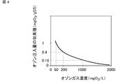
図4は、汚泥含有処理水に注入するオゾンの濃度とオゾン注入量の収束値の関係について、実験を行った結果を示している。図4において、横軸はオゾンガス濃度(mgO3/L)、縦軸はオゾン注入量の収束値(mgO3/gSS)である。なお、縦軸のオゾン注入量の収束値は、オゾンガス濃度50mgO3/Lの時のオゾン注入量の収束値を1とした時の相対値である。実験の結果、注入するオゾンの濃度が高いほどオゾン注入量の収束値が小さく、必要なオゾン使用量が少ないことを確認した。 FIG. 4 shows the results of experiments on the relationship between the concentration of ozone injected into sludge-containing treated water and the convergence value of the ozone injection amount. In FIG. 4, the horizontal axis is the ozone gas concentration (mgO 3 / L), and the vertical axis is the convergence value of the ozone injection amount (mgO 3 / gSS). The convergence value of the ozone injection amount on the vertical axis is a relative value when the convergence value of the ozone injection amount at an ozone gas concentration of 50 mgO 3 / L is 1. As a result of the experiment, it was confirmed that the higher the concentration of ozone to be injected, the smaller the convergence value of the ozone injection amount, and the smaller the required ozone usage amount.
この実験結果から、演算及び制御装置21は、決定した汚泥引抜流量及びオゾン使用量に基づいて、エジェクタ17における気液流量比が最小値となり且つオゾン濃度が最高値となるように、配管6gを循環する汚泥含有処理水の流量とエジェクタ17に注入されるオゾンの濃度及び流量を制御することが望ましい。
From this experimental result, the calculation and
本実施の形態2によれば、上記実施の形態1と同様の効果に加え、オゾン処理において高濃度オゾンを用いることにより、上記実施の形態1よりもさらにオゾン処理効率の向上が図られ、オゾン使用量を低減することが可能である。これにより、オゾン発生器12を含めた初期費用とオゾン発生、注入のランニングコストを抑制することができる。また、オゾン濃縮器13で吸着されなかった酸素ガスをオゾン発生器12に返送し、再利用するようにしたので、ランニングコストをさらに低減することができる。
According to the second embodiment, in addition to the same effect as that of the first embodiment, the use of high-concentration ozone in the ozone treatment further improves the ozone treatment efficiency as compared with the first embodiment, and ozone. It is possible to reduce the amount used. As a result, the initial cost including the
実施の形態3.
図5は、本発明の実施の形態3に係る廃水処理システムの構成を示す模式図である。なお、図5において、図1と同一部分には同一符号を付している。本実施の形態3に係る廃水処理システムは、ノズル径が異なる複数のエジェクタ17a、17b、17c(総称してエジェクタ17と記す)と、各エジェクタ17に接続されたエジェクタ液ライン切換弁22及びエジェクタガスライン切換弁23を備えている。それ以外の構成及び各部における処理、作用については、上記実施の形態1及び実施の形態2と同様であるので、ここでは説明を省略する
FIG. 5 is a schematic view showing the configuration of the wastewater treatment system according to the third embodiment of the present invention. In FIG. 5, the same parts as those in FIG. 1 are designated by the same reference numerals. The wastewater treatment system according to the third embodiment includes a plurality of
本実施の形態3では、演算及び制御装置21は、エジェクタ液ライン切換弁22及びエジェクタガスライン切換弁23にそれぞれ信号接続されている。演算及び制御装置21は、上記実施の形態1と同様に、データ蓄積装置19から生物処理槽1内の混合液の汚泥濃度及び水質データ等を取得し、実験データ入力装置20に格納された相関データを参照して、適切な汚泥処理比とオゾン注入量の収束値を計算し、それらを満たすように、汚泥引抜流量とオゾン使用量を決定する。
In the third embodiment, the calculation and
さらに、演算及び制御装置21は、複数のエジェクタ17a、17b、17cの中から決定された汚泥引抜流量とオゾン使用量に最適なエジェクタ17を決定し、そのエジェクタ17に循環汚泥及びオゾンが供給されるようにエジェクタ液ライン切換弁22とエジェクタガスライン切換弁23を切り換える。
Further, the calculation and
本実施の形態3によれば、上記実施の形態1及び実施の形態2と同様の効果に加え、ノズル径が異なる複数のエジェクタ17a、17b、17cを備えることにより、対応可能な循環汚泥の流量の範囲が広くなる。これにより、生物処理槽1に流入する廃水W1の水量、水質、及び温度等の変動が大きく余剰汚泥の発生量の変動が大きい場合にも、安定して放流水質基準を満たし、且つ最適な汚泥減容効果が得られる。なお、本発明は、その発明の範囲内において、各実施の形態を自由に組み合わせたり、各実施の形態を適宜、変形、省略したりすることが可能である。
According to the third embodiment, in addition to the same effects as those of the first and second embodiments, the flow rate of circulating sludge that can be dealt with by providing a plurality of
本発明は、有機性廃水を生物処理する際に発生する余剰汚泥を、オゾンを利用して減容化する廃水処理システムとして利用することができる。 INDUSTRIAL APPLICABILITY The present invention can be used as a wastewater treatment system for reducing the volume of excess sludge generated during biological treatment of organic wastewater by using ozone.
1 生物処理槽、2 散気装置、3 空気供給装置、4 汚泥濃度測定器、5a、5b、5c 水質測定器、6a、6b、6c、6d、6e、6f、6g 配管、7 固液分離槽、8 消毒池、9 オゾン反応槽、10a、10b 汚泥流量計、11a 汚泥引抜ポンプ、11b 汚泥循環ポンプ、12 オゾン発生器、13 オゾン濃縮器、14a、14b、14c 配管、15 オゾンガス圧力計、16 オゾンガス流量計、17、17a、17b、17c エジェクタ、18 排オゾン分解装置、19 データ蓄積装置、20 実験データ入力装置、21 演算及び制御装置、22 エジェクタ液ライン切換弁、23 エジェクタガスライン切換弁 1 Biological treatment tank, 2 Air diffuser, 3 Air supply device, 4 Sludge concentration measuring device, 5a, 5b, 5c Water quality measuring device, 6a, 6b, 6c, 6d, 6e, 6f, 6g piping, 7 Solid-liquid separation tank , 8 disinfection pond, 9 ozone reaction tank, 10a, 10b sludge flow meter, 11a sludge extraction pump, 11b sludge circulation pump, 12 ozone generator, 13 ozone concentrator, 14a, 14b, 14c piping, 15 ozone gas pressure gauge, 16 Ozone gas flow meter, 17, 17a, 17b, 17c ejector, 18 exhaust ozone decomposition device, 19 data storage device, 20 experimental data input device, 21 calculation and control device, 22 ejector liquid line switching valve, 23 ejector gas line switching valve
Claims (16)
前記生物処理槽で生成された前記汚泥含有処理水を濃縮汚泥と処理水に分離する固液分離部と、
前記生物処理槽で生成された前記汚泥含有処理水、または前記固液分離部で分離された前記濃縮汚泥を所定の汚泥引抜流量で引き抜いてオゾン処理を行い、処理後の前記汚泥含有処理水または前記濃縮汚泥を前記生物処理槽に返送するオゾン反応部と、
オゾンを生成し前記オゾン反応部に供給するオゾン発生器と、
前記生物処理槽内の前記汚泥含有処理水を含む混合液の汚泥濃度を測定する汚泥濃度測定手段と、
前記混合液、前記処理水、及び前記処理水を消毒した放流水それぞれの、汚泥濃度を除く水質データを測定する水質測定手段と、
前記混合液の汚泥濃度に基づいて汚泥引抜流量を決定し、前記混合液の汚泥濃度と汚泥引抜流量の積に基づいて前記オゾン処理におけるオゾン使用量を決定すると共に、前記水質測定手段によりそれぞれ測定された前記混合液、前記処理水、及び前記放流水のいずれか1つ以上の水質データに基づいて汚泥引抜流量及びオゾン使用量を調整する演算及び制御装置を備えたことを特徴とする廃水処理システム。 A biological treatment tank that biologically treats organic wastewater under aerobic conditions to produce sludge-containing treated water containing activated sludge.
A solid-liquid separating section for separating the sludge containing treated water produced by the biological treatment tank to treatment water a concentrated sludge,
Performs ozone treatment is withdrawn the biological treatment the sludge-containing treated water produced by the vessel, or the concentrated sludge separated by the solid-liquid separation unit at a predetermined sludge withdrawal rate, after processing the sludge-containing process water or an ozone reaction unit to return the concentrated sludge to the biological treatment tank,
An ozone generator that generates ozone and supplies it to the ozone reaction unit,
Sludge concentration measuring means for measuring the sludge concentration in the mixture containing the sludge-containing treated water of the biological treatment tank,
The mixed solution, wherein the treated water, and each of the discharge water which has been disinfected the treated water, and water quality measuring means for measuring the water quality data except sludge concentration,
The mixture based on the sludge concentration to determine the sludge withdrawal rate, the determining ozone usage in the ozone treatment on the basis of a product of the sludge concentration and sludge withdrawal rate of the mixed solution, respectively measured by the quality measuring means it has been the mixed solution, the treated water, and wastewater treatment, characterized in that it comprises an arithmetic and control unit for adjusting the sludge withdrawal rate and ozone usage based on any one or more of the water quality data of the discharged water system.
前記生物処理工程で生成された前記汚泥含有処理水を濃縮汚泥と処理水に分離する固液分離工程と、
前記生物処理工程で生成された前記汚泥含有処理水を含む混合液、前記処理水、及び前記処理水を消毒した放流水それぞれの、汚泥濃度を除く水質データを取得する水質データ取得工程と、
前記生物処理工程で生成された前記汚泥含有処理水、または前記固液分離工程で分離された前記濃縮汚泥を所定の汚泥引抜流量で引き抜いてオゾン処理を行う改質工程とを含み、
前記改質工程において、前記混合液の汚泥濃度に基づいて汚泥引抜流量を決定し、前記混合液の汚泥濃度と汚泥引抜流量の積に基づいて前記オゾン処理におけるオゾン使用量を決定すると共に、前記混合液、前記処理水、及び前記放流水のいずれか1つ以上の水質データに基づいて汚泥引抜流量及びオゾン使用量を調整することを特徴とする廃水処理方法。 A biological treatment process in which organic wastewater is biologically treated under aerobic conditions to produce sludge-containing treated water containing activated sludge.
A solid-liquid separation step of separating said sludge-containing treated water generated in the biological treatment step in the process water and concentrated sludge,
A water quality data acquisition step of acquiring water quality data excluding sludge concentration of each of the mixed solution containing the sludge-containing treated water produced in the biological treatment step, the treated water, and the discharged water obtained by disinfecting the treated water.
And a reforming step of the pulling out biological treatment the sludge-containing treated water produced in step, or the concentrated sludge separated by the solid-liquid separation step at a predetermined sludge withdrawal rate performing ozone treatment,
Wherein in the reforming step, based on the sludge concentration in the mixture was determined sludge withdrawal rate, and determines the ozone consumption in the ozone treatment on the basis of a product of the sludge concentration and sludge withdrawal rate of the mixed solution, the mixture, the treated water, wastewater treatment method characterized by adjusting the sludge withdrawal rate and ozone usage based on any one or more of the water quality data of the及beauty release water.
Priority Applications (2)
| Application Number | Priority Date | Filing Date | Title |
|---|---|---|---|
| JP2017116488A JP6877255B2 (en) | 2017-06-14 | 2017-06-14 | Wastewater treatment system and wastewater treatment method |
| CN201810134197.6A CN109081499B (en) | 2017-06-14 | 2018-02-09 | Wastewater treatment system and wastewater treatment method |
Applications Claiming Priority (1)
| Application Number | Priority Date | Filing Date | Title |
|---|---|---|---|
| JP2017116488A JP6877255B2 (en) | 2017-06-14 | 2017-06-14 | Wastewater treatment system and wastewater treatment method |
Publications (3)
| Publication Number | Publication Date |
|---|---|
| JP2019000781A JP2019000781A (en) | 2019-01-10 |
| JP2019000781A5 JP2019000781A5 (en) | 2020-01-30 |
| JP6877255B2 true JP6877255B2 (en) | 2021-05-26 |
Family
ID=64839578
Family Applications (1)
| Application Number | Title | Priority Date | Filing Date |
|---|---|---|---|
| JP2017116488A Active JP6877255B2 (en) | 2017-06-14 | 2017-06-14 | Wastewater treatment system and wastewater treatment method |
Country Status (2)
| Country | Link |
|---|---|
| JP (1) | JP6877255B2 (en) |
| CN (1) | CN109081499B (en) |
Families Citing this family (6)
| Publication number | Priority date | Publication date | Assignee | Title |
|---|---|---|---|---|
| CN113382969B (en) * | 2019-02-15 | 2023-05-05 | 三菱电机株式会社 | Water treatment system and water treatment method |
| JP7282020B2 (en) * | 2019-12-06 | 2023-05-26 | 三菱電機株式会社 | Sludge treatment system and sludge treatment method |
| CN113772912B (en) * | 2021-11-11 | 2022-03-22 | 临沂朝日电子有限公司 | Environmental protection sludge separation device |
| JP7286035B1 (en) * | 2022-03-24 | 2023-06-02 | 三菱電機株式会社 | Water treatment control system and method for controlling water treatment equipment |
| WO2024100831A1 (en) * | 2022-11-10 | 2024-05-16 | 三菱電機株式会社 | Solubilization apparatus and solubilization method |
| CN115677020B (en) * | 2022-12-07 | 2023-12-05 | 如东深水环境科技有限公司 | Method for treating organic wastewater by combining ozone oxidation and biological activated carbon |
Family Cites Families (10)
| Publication number | Priority date | Publication date | Assignee | Title |
|---|---|---|---|---|
| JP3672117B2 (en) * | 1995-10-06 | 2005-07-13 | 株式会社荏原製作所 | Organic wastewater treatment method and apparatus |
| JP3383498B2 (en) * | 1995-11-30 | 2003-03-04 | 株式会社荏原製作所 | Organic wastewater treatment method |
| FR2843106B1 (en) * | 2002-08-05 | 2004-10-08 | Omnium Traitement Valorisa | PROCESS AND PLANT FOR TREATING SLUDGE FROM BIOLOGICAL WATER PURIFICATION PLANTS |
| JP4421372B2 (en) * | 2004-05-13 | 2010-02-24 | パナソニック環境エンジニアリング株式会社 | Sewage treatment equipment |
| JP2007253011A (en) * | 2006-03-22 | 2007-10-04 | Kurita Water Ind Ltd | Biological treatment method and apparatus for organic liquid waste |
| JP5779321B2 (en) * | 2010-06-18 | 2015-09-16 | シャープ株式会社 | High concentration ozone water manufacturing method and high concentration ozone water manufacturing apparatus |
| JP4950362B1 (en) * | 2011-04-13 | 2012-06-13 | 三菱電機株式会社 | Ozone generation system and operation method of ozone generation system |
| JP5922406B2 (en) * | 2011-12-28 | 2016-05-24 | 三菱重工メカトロシステムズ株式会社 | Wastewater treatment equipment |
| CN103359875B (en) * | 2012-03-27 | 2015-07-22 | 三菱电机株式会社 | Waste water treatment method and waste water treatment system |
| JP6129289B2 (en) * | 2015-12-17 | 2017-05-17 | 三菱電機株式会社 | Water treatment system and water treatment method |
-
2017
- 2017-06-14 JP JP2017116488A patent/JP6877255B2/en active Active
-
2018
- 2018-02-09 CN CN201810134197.6A patent/CN109081499B/en active Active
Also Published As
| Publication number | Publication date |
|---|---|
| CN109081499B (en) | 2022-06-24 |
| CN109081499A (en) | 2018-12-25 |
| JP2019000781A (en) | 2019-01-10 |
Similar Documents
| Publication | Publication Date | Title |
|---|---|---|
| JP6877255B2 (en) | Wastewater treatment system and wastewater treatment method | |
| US20130140232A1 (en) | Method and system for ozone vent gas reuse in wastewater treatment | |
| US20090145827A1 (en) | Water Treatment System | |
| JP2011194373A (en) | Treatment method and apparatus of rice processing wastewater | |
| JP4410163B2 (en) | Waste water ozone treatment method and ozone treatment apparatus | |
| JP6203560B2 (en) | Organic wastewater treatment method and organic wastewater treatment apparatus | |
| CA3217446A1 (en) | Systems and methods of gas infusion for wastewater treatment | |
| JP6656138B2 (en) | Water treatment system and water treatment method | |
| JP4617787B2 (en) | Sewage treatment system | |
| JP2012066186A (en) | Water treatment apparatus | |
| JP6424807B2 (en) | Water treatment system and water treatment method | |
| GB2473440A (en) | Apparatus and process for ozone generation and ozonation of oils | |
| CN113382969B (en) | Water treatment system and water treatment method | |
| JP3598022B2 (en) | Water treatment method using ozone and hydrogen peroxide | |
| JP7241608B2 (en) | Wastewater treatment system and wastewater treatment method | |
| JP2009214073A (en) | Treatment method for nitrogen-containing organic wastewater and treatment apparatus therfor | |
| JP2008188533A (en) | Water treatment apparatus | |
| CN111886206A (en) | Sludge discharge control device, water treatment system, and sludge discharge control method | |
| JPWO2019234909A1 (en) | Water treatment system and water treatment method | |
| JP2007222830A (en) | Treatment method of nitrogen-containing organic wastewater, and treatment apparatus for it | |
| JP2007209889A (en) | Surplus sludge treatment method | |
| JP6593975B2 (en) | Water treatment method and water treatment apparatus | |
| JP2004025051A (en) | Organic wastewater treatment method and organic wastewater treatment apparatus | |
| JPS6048196A (en) | Method for removing phosphorus from organic waste liquid | |
| JP5760182B2 (en) | Organic waste water treatment apparatus and organic waste water treatment method |
Legal Events
| Date | Code | Title | Description |
|---|---|---|---|
| A521 | Request for written amendment filed |
Free format text: JAPANESE INTERMEDIATE CODE: A523 Effective date: 20191213 |
|
| A621 | Written request for application examination |
Free format text: JAPANESE INTERMEDIATE CODE: A621 Effective date: 20191213 |
|
| RD02 | Notification of acceptance of power of attorney |
Free format text: JAPANESE INTERMEDIATE CODE: A7422 Effective date: 20191213 |
|
| A977 | Report on retrieval |
Free format text: JAPANESE INTERMEDIATE CODE: A971007 Effective date: 20201028 |
|
| A131 | Notification of reasons for refusal |
Free format text: JAPANESE INTERMEDIATE CODE: A131 Effective date: 20201104 |
|
| A521 | Request for written amendment filed |
Free format text: JAPANESE INTERMEDIATE CODE: A523 Effective date: 20201224 |
|
| TRDD | Decision of grant or rejection written | ||
| A01 | Written decision to grant a patent or to grant a registration (utility model) |
Free format text: JAPANESE INTERMEDIATE CODE: A01 Effective date: 20210406 |
|
| A61 | First payment of annual fees (during grant procedure) |
Free format text: JAPANESE INTERMEDIATE CODE: A61 Effective date: 20210427 |
|
| R151 | Written notification of patent or utility model registration |
Ref document number: 6877255 Country of ref document: JP Free format text: JAPANESE INTERMEDIATE CODE Ref document number: 6877255 Country of ref document: JP Free format text: JAPANESE INTERMEDIATE CODE: R151 |
|
| R250 | Receipt of annual fees |
Free format text: JAPANESE INTERMEDIATE CODE: R250 |